Embed Size (px)
Citation preview
1
Reviewer’s Guide
Frame Capture Analysis Tool FCAT + 4K Support
V15 – 6/1/2015
V 1 5 – 6 / 1 7 / 2 0 1 5 2
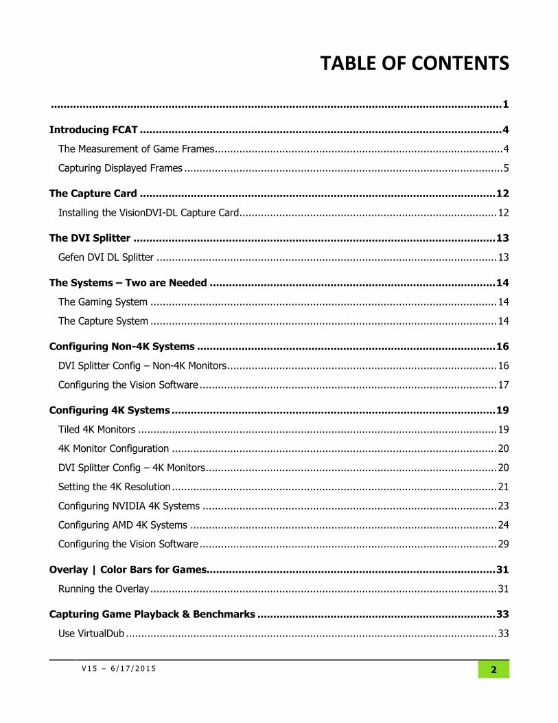
TABLE OF CONTENTS
.............................................................................................................................................. 1
Introducing FCAT .................................................................................................................. 4
The Measurement of Game Frames .............................................................................................. 4
Capturing Displayed Frames ........................................................................................................ 5
The Capture Card ................................................................................................................ 12
Installing the VisionDVI-DL Capture Card .................................................................................... 12
The DVI Splitter .................................................................................................................. 13
Gefen DVI DL Splitter ............................................................................................................... 13
The Systems – Two are Needed .......................................................................................... 14
The Gaming System ................................................................................................................. 14
The Capture System ................................................................................................................. 14
Configuring Non-4K Systems .............................................................................................. 16
DVI Splitter Config – Non-4K Monitors ........................................................................................ 16
Configuring the Vision Software ................................................................................................. 17
Configuring 4K Systems ...................................................................................................... 19
Tiled 4K Monitors ..................................................................................................................... 19
4K Monitor Configuration .......................................................................................................... 20
DVI Splitter Config – 4K Monitors ............................................................................................... 20
Setting the 4K Resolution .......................................................................................................... 21
Configuring NVIDIA 4K Systems ................................................................................................ 23
Configuring AMD 4K Systems .................................................................................................... 24
Configuring the Vision Software ................................................................................................. 29
Overlay | Color Bars for Games........................................................................................... 31
Running the Overlay ................................................................................................................. 31
Capturing Game Playback & Benchmarks ........................................................................... 33
Use VirtualDub ......................................................................................................................... 33
V 1 5 – 6 / 1 7 / 2 0 1 5 3
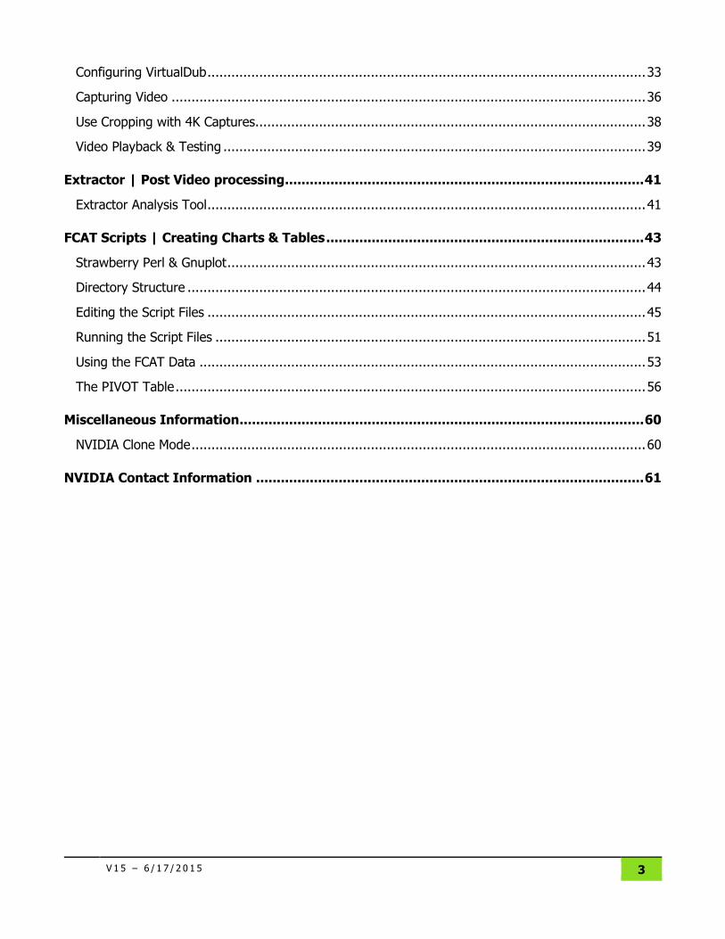
Configuring VirtualDub .............................................................................................................. 33
Capturing Video ....................................................................................................................... 36
Use Cropping with 4K Captures.................................................................................................. 38
Video Playback & Testing .......................................................................................................... 39
Extractor | Post Video processing ....................................................................................... 41
Extractor Analysis Tool .............................................................................................................. 41
FCAT Scripts | Creating Charts & Tables ............................................................................. 43
Strawberry Perl & Gnuplot ......................................................................................................... 43
Directory Structure ................................................................................................................... 44
Editing the Script Files .............................................................................................................. 45
Running the Script Files ............................................................................................................ 51
Using the FCAT Data ................................................................................................................ 53
The PIVOT Table ...................................................................................................................... 56
Miscellaneous Information .................................................................................................. 60
NVIDIA Clone Mode .................................................................................................................. 60
NVIDIA Contact Information .............................................................................................. 61
4
INTRODUCING FCAT
FCAT stands for Frame Capture Analysis Tool
FCAT allows for the analysis of individual frames captured from single- and multi-GPU configurations.
NVIDIA has been developing and using FCAT internally over the last two years to analyze and improve
the single GPU and SLI experience that we deliver to our GeForce GTX customers. We have made this
tool available to help press and editors to fully understand how game frames are processed and
delivered, especially in multi-GPU configurations. FCAT is freely modifiable and redistributable, and we
expect third-parties to replicate and ultimately replace FCAT tools with their own.
The Measurement of Game Frames
The goal of FCAT is to analyze the way frames are seen by gamers
Currently, software is used to measure the game frames that the GPU delivers. This is typically
characterized as frames per second (FPS). However, software-only methods have problems because
they only measure the frames that the game engine generates. Software cannot measure the frames
that are actually delivered to the display, which affects the overall gaming experience.
FCAT is a method for measuring actual frames that have been delivered to the display; the frames that
you actually see. FCAT works in concert with a high-speed capture card to capture a color overlay that
is painted on every frame that is drawn to the display. Included are tools that take the color bar
information, measure the size of them, and determine if any of the color bars are missing. Perl scripts
are then used to analyze that data, and turn the data into graphs and charts.
What is included with the FCAT Files Overlay
o DXFrameOverlay.dll
DXFrameOverlay64.dll
EnableOverlay.exe
EnableOverlay64.exe
Overlays a fixed color sequence over the game while it’s running. There is a separate
overlay executable for 64-bit games. Both can be run simultaneously.
Extractor
o Extractor.exe
Output = CSV of overlay colors and scanlines
FCAT Reviewer's Guide INTRODUCING FCAT
5
Scripting and Analysis Tools
o doall.pl
PERL helper script to generate a big batch file.
o fcat.pl
PERL script that combines bars and identifies runts and drops
Output = CSV of HW frametimes (similar to Fraps), and CSV of Original FPS, New FPS,
Runts, drops
o gen_percentiles.pl
PERL script that generates the 95 and 99th frametime percentile calculations.
o pivot.pl
PERL script that generates a summary CSV file (good for a pivot table).
o example.bat
The example.bat file is where you specify the directory locations of the data files, the
config and batch files, and the gpu and game values that you would like included in the
charts.
o example.cfg
The example.cfg file allows for the customization of the charts, including the alignment
of multiple data lines, and the cropping of data outside the regions of the benchmark.
o example.plt
The example.plt file allows for the configuration of elements in the charts, including
title/legend/axis fonts types, colors, and sizes.
Capturing Displayed Frames Capturing displayed frames is very difficult. If you control the driver, it can be done with software. But
drivers can be written to hide effects like dropped and runt frames (described below). What is required
is a method that measures the actual output from the DVI connector before it’s delivered to the
monitor.
We have found that placing a high-speed capture card in a special “capture system” that captures the
game system’s DVI port output can be used to accurately measure frames. If the captured data is
saved as a movie, and overlay software is used to draw color bars on the left-hand side of every frame,
you then have some useful data. All that’s needed at this point is a software extractor that looks at the
captured movie, and extracts the timing of those color bars. Visually, you can step through the
captured video data and see problems based on the expected color bar sequence and individual color
bar length (to be described in more detail below).
We have written this overlay software, and we have created the extractor that simply generates an
Excel file off the bar lengths. Simple Perl software is then used to process the bar-length data across all
of your GPUs and all of your games, with the result being some very informative graphs.
FCAT Reviewer's Guide INTRODUCING FCAT
6
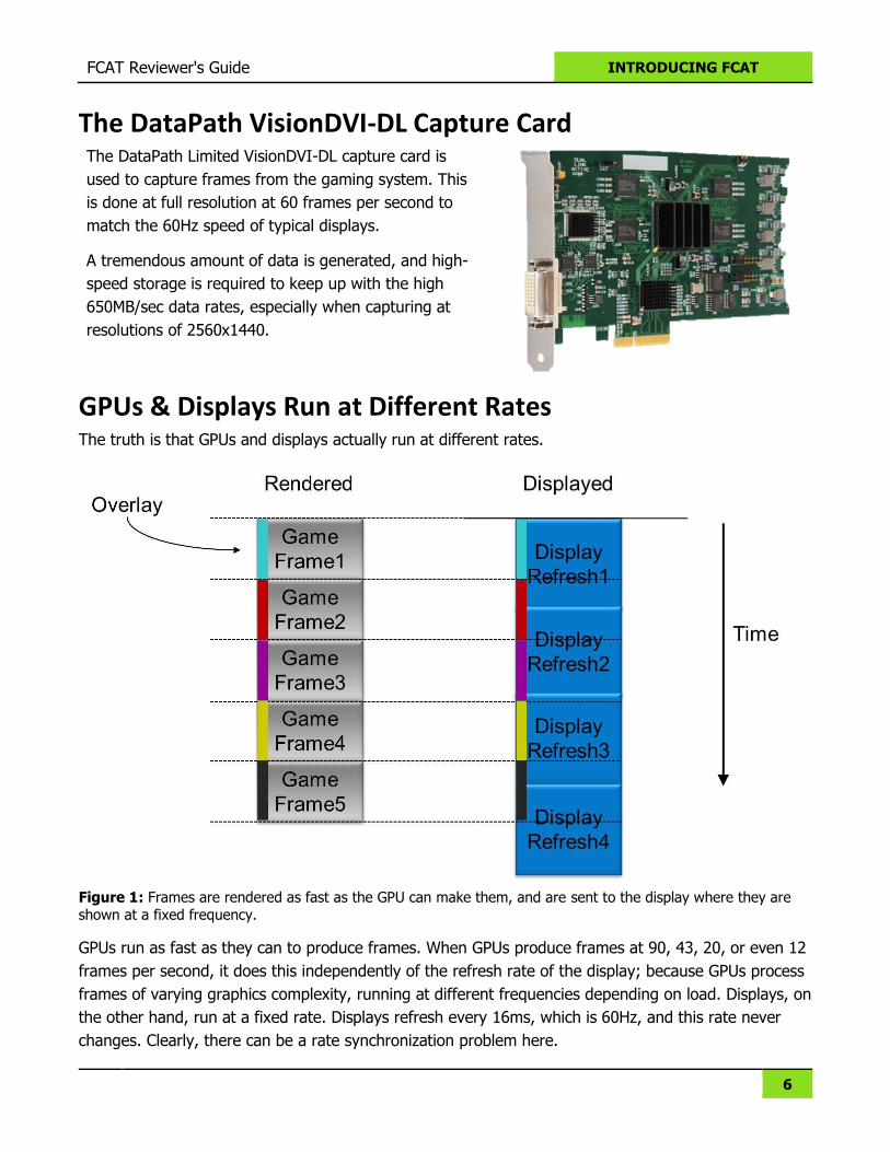
The DataPath VisionDVI-DL Capture Card The DataPath Limited VisionDVI-DL capture card is
used to capture frames from the gaming system. This
is done at full resolution at 60 frames per second to
match the 60Hz speed of typical displays.
A tremendous amount of data is generated, and high-
speed storage is required to keep up with the high
650MB/sec data rates, especially when capturing at
resolutions of 2560x1440.
GPUs & Displays Run at Different Rates The truth is that GPUs and displays actually run at different rates.
Figure 1: Frames are rendered as fast as the GPU can make them, and are sent to the display where they are shown at a fixed frequency.
GPUs run as fast as they can to produce frames. When GPUs produce frames at 90, 43, 20, or even 12
frames per second, it does this independently of the refresh rate of the display; because GPUs process
frames of varying graphics complexity, running at different frequencies depending on load. Displays, on
the other hand, run at a fixed rate. Displays refresh every 16ms, which is 60Hz, and this rate never
changes. Clearly, there can be a rate synchronization problem here.
FCAT Reviewer's Guide INTRODUCING FCAT
7
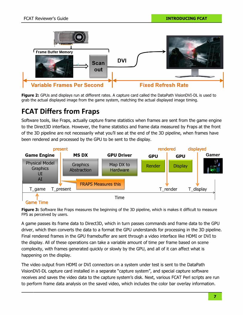
Figure 2: GPUs and displays run at different rates. A capture card called the DataPath VisionDVI-DL is used to grab the actual displayed image from the game system, matching the actual displayed image timing.
FCAT Differs from Fraps Software tools, like Fraps, actually capture frame statistics when frames are sent from the game engine
to the Direct3D interface. However, the frame statistics and frame data measured by Fraps at the front
of the 3D pipeline are not necessarily what you’ll see at the end of the 3D pipeline, when frames have
been rendered and processed by the GPU to be sent to the display.
Figure 3: Software like Fraps measures the beginning of the 3D pipeline, which is makes it difficult to measure
FPS as perceived by users.
A game passes its frame data to Direct3D, which in turn passes commands and frame data to the GPU
driver, which then converts the data to a format the GPU understands for processing in the 3D pipeline.
Final rendered frames in the GPU framebuffer are sent through a video interface like HDMI or DVI to
the display. All of these operations can take a variable amount of time per frame based on scene
complexity, with frames generated quickly or slowly by the GPU, and all of it can affect what is
happening on the display.
The video output from HDMI or DVI connectors on a system under test is sent to the DataPath
VisionDVI-DL capture card installed in a separate “capture system”, and special capture software
receives and saves the video data to the capture system’s disk. Next, various FCAT Perl scripts are run
to perform frame data analysis on the saved video, which includes the color bar overlay information.
FCAT Reviewer's Guide INTRODUCING FCAT
8
FCAT is able to provide frame statistics matching exactly what the user actual sees on the display
screen of the system under test. Problems that can occur in the 3D pipeline, such as dropped frames or
“runt” frames (explained below), or variations in frametimes caused by 3D pipeline processing can be
exposed by FCAT.
A major difference between FCAT and Fraps is that Fraps cannot measure what is actually output to
the display, where FCAT is built to measure frame characteristics at the display output. What is actually
drawn to the display can provide very different results than measuring the input to the GPU rendering
pipeline.
Dropped & Runt Frames
For smooth game animation to work perfectly, the game frames should be displayed at an even rate,
and each frame should be of equal frametime to the frame that came before it. Such exact frame-to-
frame timing rarely happens in reality.
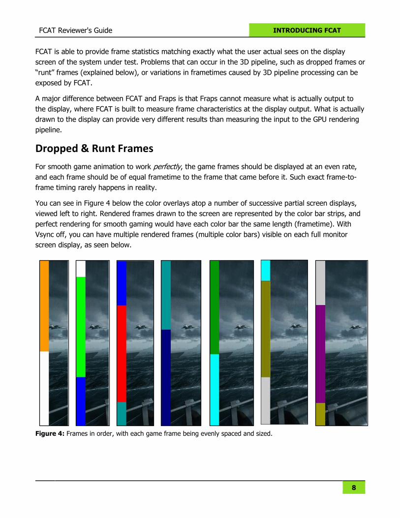
You can see in Figure 4 below the color overlays atop a number of successive partial screen displays,
viewed left to right. Rendered frames drawn to the screen are represented by the color bar strips, and
perfect rendering for smooth gaming would have each color bar the same length (frametime). With
Vsync off, you can have multiple rendered frames (multiple color bars) visible on each full monitor
screen display, as seen below.
Figure 4: Frames in order, with each game frame being evenly spaced and sized.
FCAT Reviewer's Guide INTRODUCING FCAT
9
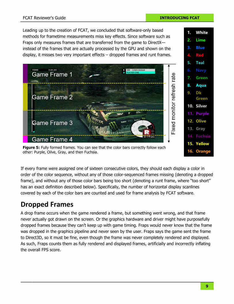
Leading up to the creation of FCAT, we concluded that software-only based
methods for frametime measurements miss key effects. Since software such as
Fraps only measures frames that are transferred from the game to DirectX—
instead of the frames that are actually processed by the GPU and shown on the
display, it misses two very important effects – dropped frames and runt frames.
Figure 5: Fully formed frames. You can see that the color bars correctly follow each other: Purple, Oilve, Gray, and then Fuchsia.
1. White
2. Lime
3. Blue
4. Red
5. Teal
6. Navy
7. Green
8. Aqua
9. Dk
Green
10. Silver
11. Purple
12. Olive
13. Gray
14. Fuchsia
15. Yellow
16. Orange
If every frame were assigned one of sixteen consecutive colors, they should each display a color in
order of the color sequence, without any of those color-sequenced frames missing (denoting a dropped
frame), and without any of those color bars being too short (denoting a runt frame, where “too short”
has an exact definition described below). Specifically, the number of horizontal display scanlines
covered by each of the color bars are counted and used for frame analysis by FCAT software.
Dropped Frames A drop frame occurs when the game rendered a frame, but something went wrong, and that frame
never actually got drawn on the screen. Or the graphics hardware and driver might have purposefully
dropped frames because they can’t keep up with game timing. Fraps would never know that the frame
was dropped in the graphics pipeline and never seen by the user. Fraps says the game sent the frame
to Direct3D, so it must be fine, even though the frame was never completely rendered and displayed.
As such, Fraps counts them as fully rendered and displayed frames, artificially and incorrectly inflating
the overall FPS score.
FCAT Reviewer's Guide INTRODUCING FCAT
10
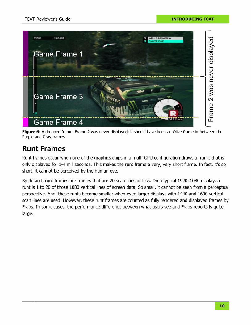
Figure 6: A dropped frame. Frame 2 was never displayed; it should have been an Olive frame in-between the
Purple and Gray frames.
Runt Frames
Runt frames occur when one of the graphics chips in a multi-GPU configuration draws a frame that is
only displayed for 1-4 milliseconds. This makes the runt frame a very, very short frame. In fact, it’s so
short, it cannot be perceived by the human eye.
By default, runt frames are frames that are 20 scan lines or less. On a typical 1920x1080 display, a
runt is 1 to 20 of those 1080 vertical lines of screen data. So small, it cannot be seen from a perceptual
perspective. And, these runts become smaller when even larger displays with 1440 and 1600 vertical
scan lines are used. However, these runt frames are counted as fully rendered and displayed frames by
Fraps. In some cases, the performance difference between what users see and Fraps reports is quite
large.
FCAT Reviewer's Guide INTRODUCING FCAT
11
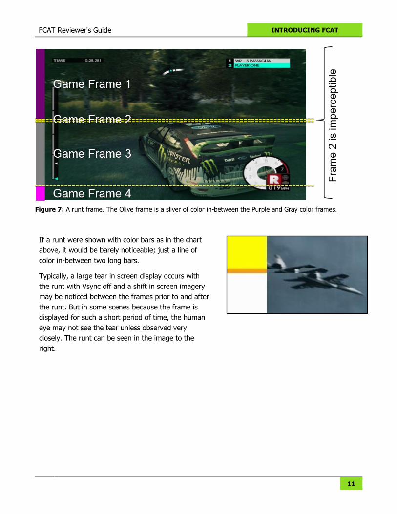
Figure 7: A runt frame. The Olive frame is a sliver of color in-between the Purple and Gray color frames.
If a runt were shown with color bars as in the chart
above, it would be barely noticeable; just a line of
color in-between two long bars.
Typically, a large tear in screen display occurs with
the runt with Vsync off and a shift in screen imagery
may be noticed between the frames prior to and after
the runt. But in some scenes because the frame is
displayed for such a short period of time, the human
eye may not see the tear unless observed very
closely. The runt can be seen in the image to the
right.
12
THE CAPTURE CARD
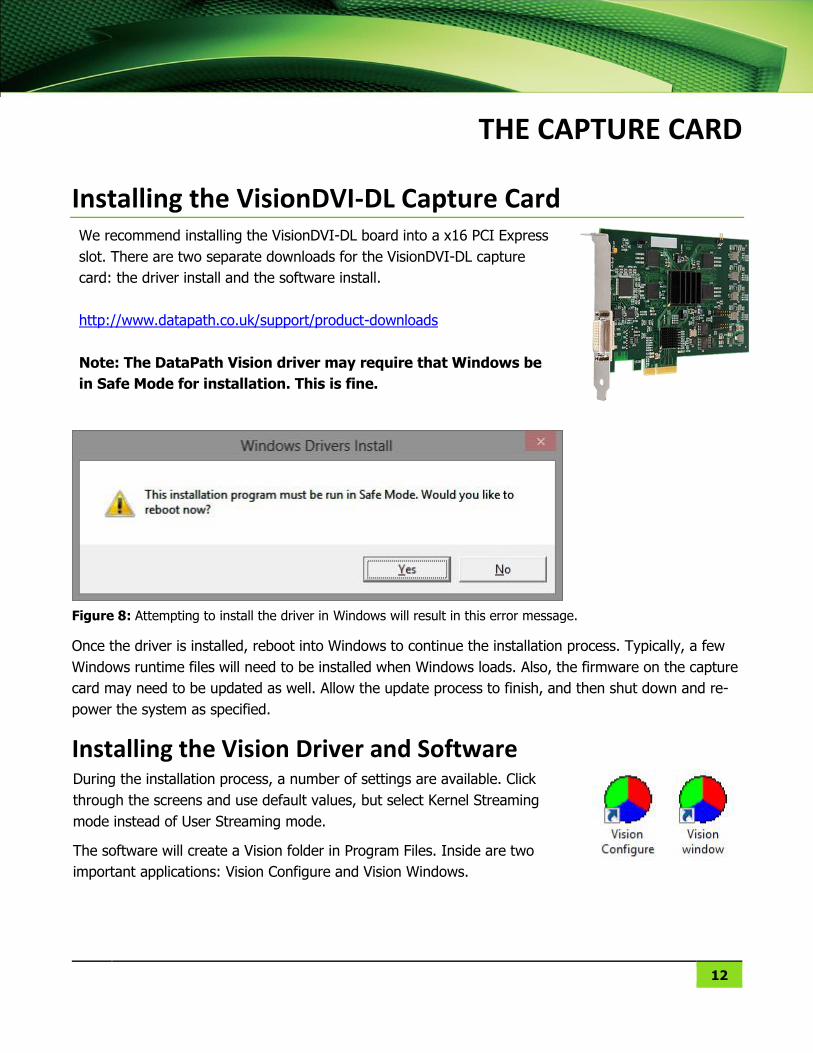
Installing the VisionDVI-DL Capture Card We recommend installing the VisionDVI-DL board into a x16 PCI Express
slot. There are two separate downloads for the VisionDVI-DL capture
card: the driver install and the software install.
http://www.datapath.co.uk/support/product-downloads
Note: The DataPath Vision driver may require that Windows be
in Safe Mode for installation. This is fine.
Figure 8: Attempting to install the driver in Windows will result in this error message.
Once the driver is installed, reboot into Windows to continue the installation process. Typically, a few
Windows runtime files will need to be installed when Windows loads. Also, the firmware on the capture
card may need to be updated as well. Allow the update process to finish, and then shut down and re-
power the system as specified.
Installing the Vision Driver and Software During the installation process, a number of settings are available. Click
through the screens and use default values, but select Kernel Streaming
mode instead of User Streaming mode.
The software will create a Vision folder in Program Files. Inside are two
important applications: Vision Configure and Vision Windows.
13
THE DVI SPLITTER
A DVI splitter is required to capture from non-NVIDIA configurations that use more than one GPU.
NVIDIA allows for the cloning of screens across two DVI connectors in SLI mode, whereas CrossFire
does not.
Gefen DVI DL Splitter
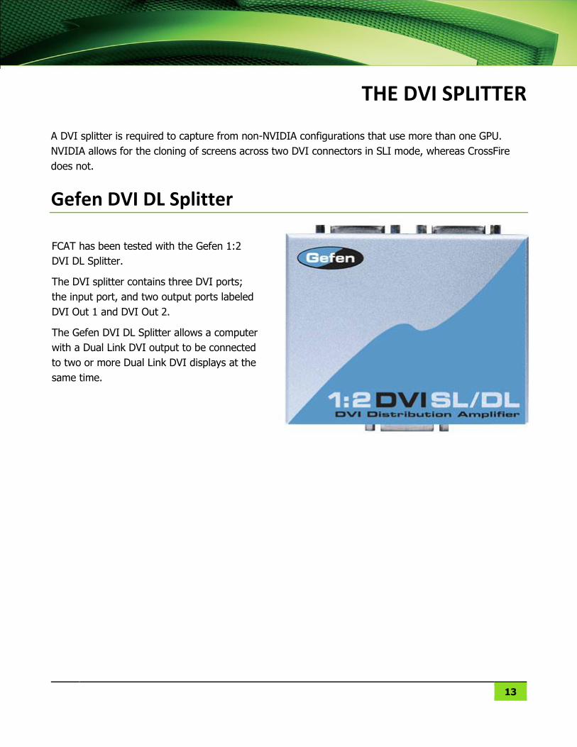
FCAT has been tested with the Gefen 1:2
DVI DL Splitter.
The DVI splitter contains three DVI ports;
the input port, and two output ports labeled
DVI Out 1 and DVI Out 2.
The Gefen DVI DL Splitter allows a computer
with a Dual Link DVI output to be connected
to two or more Dual Link DVI displays at the
same time.
14
THE SYSTEMS – TWO ARE NEEDED
The Gaming System Any system can be used to play the games. If you have existing game/benchmark systems, then we
recommend using those. Games can be captured from single or multiple GPU configurations.
The Capture System The capture system is the system that has the VisionDVI-DL capture card in it. We have found that
seating the VisionDVI-DL capture card in a x16 slot works best.
Chipset & CPU The capture system can be any type of configuration. The CPU speed is not important, and running an
overclocked capture system is not necessary nor recommended (for stability reasons).
NOTE: The VisionDVI-DL capture card seems to have resource issues when used with an Intel X79
motherboard. Ensure the latest firmware is used. Hardware features such as USB3, secondary
Ethernet, etc. may need to be disabled in the system BIOS before the capture card will work properly.
This was not experienced with non-Intel X79 motherboards.
SSD RAID Array It is recommended that an SSD RAID be set up for capturing. A tremendous amount of I/O bandwidth
is required (upwards of 650MB/sec) when capturing at 60FPS at the highest resolutions such as
5760x1440 and 1920x2160 (half of 4K). For this reason, a storage array with sufficient bandwidth is
needed.
Recommended storage solutions:
1. 3-4 SSD hard drives configured in a RAID 0 striped array.
2. A Thunderbolt motherboard and enclosure. The Promise Pegasus r4 Thunderbolt enclosure
works well when used with four SSDs.
3. PCIe storage drives from OCZ and Intel.
4. Use ImDisk to create a virtual hard disk using system memory.
http://www.ltr-data.se/opencode.html/
FCAT Reviewer's Guide THE SYSTEMS – TWO ARE NEEDED
15
Regarding SSD RAID Arrays
Do not install the Windows OS onto the RAID array. Install it on a separate single SSD so that
Windows writes do not interfere with captures, leading to unwanted inserted/dropped frames.
Make sure that all four SSD drives used in the RAID array are connected to the Intel SATA
connectors on the motherboard. Do not use third-party SATA controllers such as ASMEDIA, as
they have been shown to induce inserted frames in captures. However, the ASMEDIA SATA
connectors can be used for the Windows SSD (freeing up the Intel SATA connectors for RAID
array).
Preferably attach SSDs to the 6Gbit/sec SATA ports for optimal performance.
16
CONFIGURING NON-4K SYSTEMS
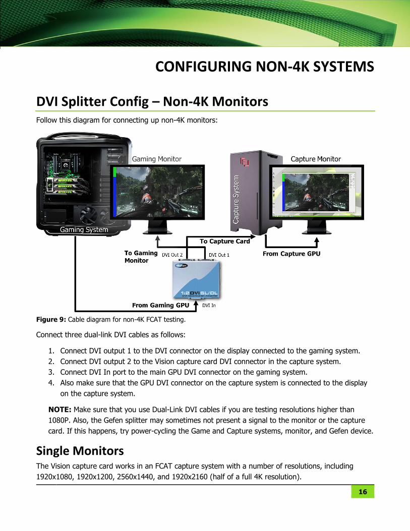
DVI Splitter Config – Non-4K Monitors Follow this diagram for connecting up non-4K monitors:
Figure 9: Cable diagram for non-4K FCAT testing.
Connect three dual-link DVI cables as follows:
1. Connect DVI output 1 to the DVI connector on the display connected to the gaming system.
2. Connect DVI output 2 to the Vision capture card DVI connector in the capture system.
3. Connect DVI In port to the main GPU DVI connector on the gaming system.
4. Also make sure that the GPU DVI connector on the capture system is connected to the display
on the capture system.
NOTE: Make sure that you use Dual-Link DVI cables if you are testing resolutions higher than
1080P. Also, the Gefen splitter may sometimes not present a signal to the monitor or the capture
card. If this happens, try power-cycling the Game and Capture systems, monitor, and Gefen device.
Single Monitors The Vision capture card works in an FCAT capture system with a number of resolutions, including
1920x1080, 1920x1200, 2560x1440, and 1920x2160 (half of a full 4K resolution).
FCAT Reviewer's Guide CONFIGURING NON-4K SYSTEMS
17
NVIDIA Surround / AMD Eyefinity NVIDIA Surround and AMD Eyefinity resolutions of 5760x1080 can be captured by hooking DVI Port A
of the DVI splitter to the GPU DVI connector that drives the far left monitor of the Surround or
Eyefinity array. You will essentially be capturing just the output of the 1920x1080 monitor that contains
the Overlay bars. If this is done, ensure that the Vision Config and VirtualDub applications are properly
configured for a 1920x1080 resolution. However, if your capture system is more easily hooked up to
the center or right-most monitor of the Surround group, you can force the overlay to be in all three of
the monitors using command-line parameters with the EnableOverlay.exe file.
Configuring the Vision Software
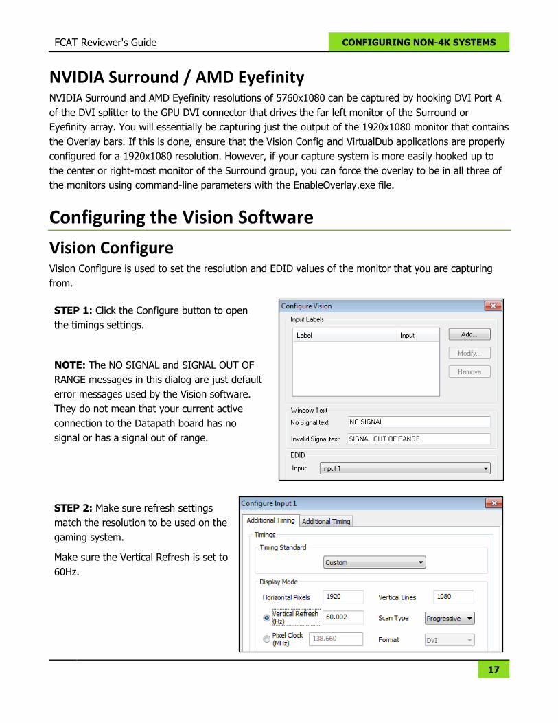
Vision Configure Vision Configure is used to set the resolution and EDID values of the monitor that you are capturing
from.
STEP 1: Click the Configure button to open
the timings settings.
NOTE: The NO SIGNAL and SIGNAL OUT OF
RANGE messages in this dialog are just default
error messages used by the Vision software.
They do not mean that your current active
connection to the Datapath board has no
signal or has a signal out of range.
STEP 2: Make sure refresh settings
match the resolution to be used on the
gaming system.
Make sure the Vertical Refresh is set to
60Hz.
FCAT Reviewer's Guide CONFIGURING NON-4K SYSTEMS
18
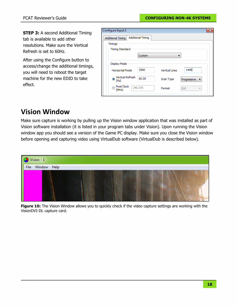
STEP 3: A second Additional Timing
tab is available to add other
resolutions. Make sure the Vertical
Refresh is set to 60Hz.
After using the Configure button to
access/change the additional timings,
you will need to reboot the target
machine for the new EDID to take
effect.
Vision Window Make sure capture is working by pulling up the Vision window application that was installed as part of
Vision software installation (it is listed in your program tabs under Vision). Upon running the Vision
window app you should see a version of the Game PC display. Make sure you close the Vision window
before opening and capturing video using VirtualDub software (VirtualDub is described below).
Figure 10: The Vision Window allows you to quickly check if the video capture settings are working with the
VisionDVI-DL capture card.
19
CONFIGURING 4K SYSTEMS
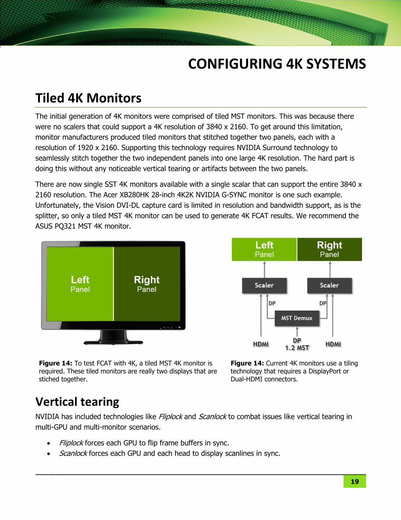
Tiled 4K Monitors The initial generation of 4K monitors were comprised of tiled MST monitors. This was because there
were no scalers that could support a 4K resolution of 3840 x 2160. To get around this limitation,
monitor manufacturers produced tiled monitors that stitched together two panels, each with a
resolution of 1920 x 2160. Supporting this technology requires NVIDIA Surround technology to
seamlessly stitch together the two independent panels into one large 4K resolution. The hard part is
doing this without any noticeable vertical tearing or artifacts between the two panels.
There are now single SST 4K monitors available with a single scalar that can support the entire 3840 x
2160 resolution. The Acer XB280HK 28-inch 4K2K NVIDIA G-SYNC monitor is one such example.
Unfortunately, the Vision DVI-DL capture card is limited in resolution and bandwidth support, as is the
splitter, so only a tiled MST 4K monitor can be used to generate 4K FCAT results. We recommend the
ASUS PQ321 MST 4K monitor.
Figure 14: To test FCAT with 4K, a tiled MST 4K monitor is
required. These tiled monitors are really two displays that are
stiched together.
Figure 14: Current 4K monitors use a tiling
technology that requires a DisplayPort or
Dual-HDMI connectors.
Vertical tearing NVIDIA has included technologies like Fliplock and Scanlock to combat issues like vertical tearing in
multi-GPU and multi-monitor scenarios.
Fliplock forces each GPU to flip frame buffers in sync.
Scanlock forces each GPU and each head to display scanlines in sync.
FCAT Reviewer's Guide CONFIGURING 4K SYSTEMS
20
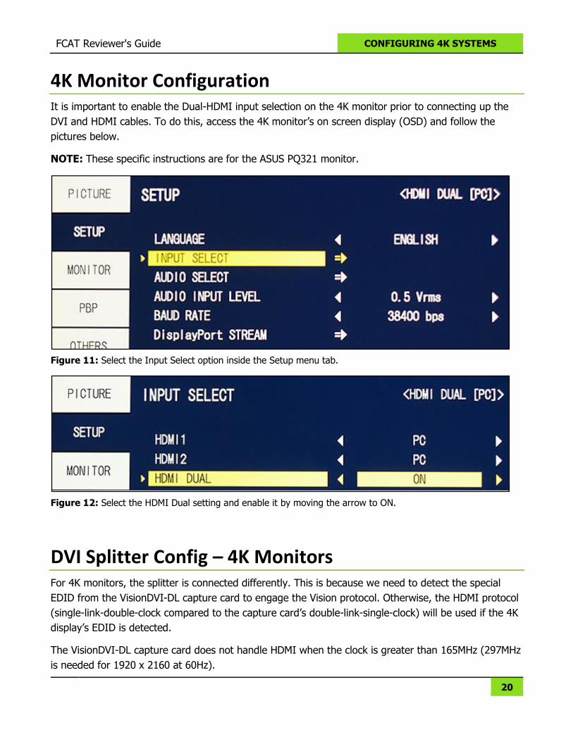
4K Monitor Configuration It is important to enable the Dual-HDMI input selection on the 4K monitor prior to connecting up the
DVI and HDMI cables. To do this, access the 4K monitor’s on screen display (OSD) and follow the
pictures below.
NOTE: These specific instructions are for the ASUS PQ321 monitor.
Figure 11: Select the Input Select option inside the Setup menu tab.
Figure 12: Select the HDMI Dual setting and enable it by moving the arrow to ON.
DVI Splitter Config – 4K Monitors For 4K monitors, the splitter is connected differently. This is because we need to detect the special
EDID from the VisionDVI-DL capture card to engage the Vision protocol. Otherwise, the HDMI protocol
(single-link-double-clock compared to the capture card’s double-link-single-clock) will be used if the 4K
display’s EDID is detected.
The VisionDVI-DL capture card does not handle HDMI when the clock is greater than 165MHz (297MHz
is needed for 1920 x 2160 at 60Hz).
FCAT Reviewer's Guide CONFIGURING 4K SYSTEMS
21
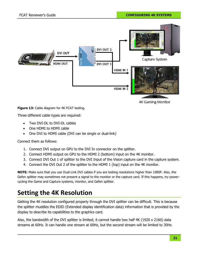
Figure 13: Cable diagram for 4K FCAT testing.
Three different cable types are required:
Two DVI-DL to DVI-DL cables
One HDMI to HDMI cable
One DVI to HDMI cable (DVI can be single or dual-link)
Connect them as follows:
1. Connect DVI output on GPU to the DVI In connector on the splitter.
2. Connect HDMI output on GPU to the HDMI 2 (bottom) input on the 4K monitor.
3. Connect DVI Out 1 of splitter to the DVI Input of the Vision capture card in the capture system.
4. Connect the DVI Out 2 of the splitter to the HDMI 1 (top) input on the 4K monitor.
NOTE: Make sure that you use Dual-Link DVI cables if you are testing resolutions higher than 1080P. Also, the
Gefen splitter may sometimes not present a signal to the monitor or the capture card. If this happens, try power-
cycling the Game and Capture systems, monitor, and Gefen splitter.
Setting the 4K Resolution Getting the 4K resolution configured properly through the DVI splitter can be difficult. This is because
the splitter muddles the EDID (Extended display identification data) information that is provided by the
display to describe its capabilities to the graphics card.
Also, the bandwidth of the DVI splitter is limited; it cannot handle two half 4K (1920 x 2160) data
streams at 60Hz. It can handle one stream at 60Hz, but the second stream will be limited to 30Hz.
FCAT Reviewer's Guide CONFIGURING 4K SYSTEMS
22
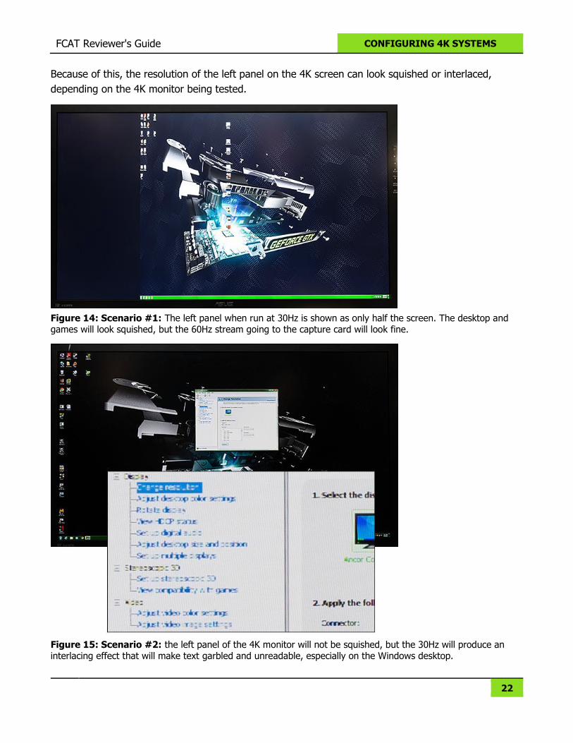
Because of this, the resolution of the left panel on the 4K screen can look squished or interlaced,
depending on the 4K monitor being tested.
Figure 14: Scenario #1: The left panel when run at 30Hz is shown as only half the screen. The desktop and games will look squished, but the 60Hz stream going to the capture card will look fine.
Figure 15: Scenario #2: the left panel of the 4K monitor will not be squished, but the 30Hz will produce an interlacing effect that will make text garbled and unreadable, especially on the Windows desktop.
FCAT Reviewer's Guide CONFIGURING 4K SYSTEMS
23
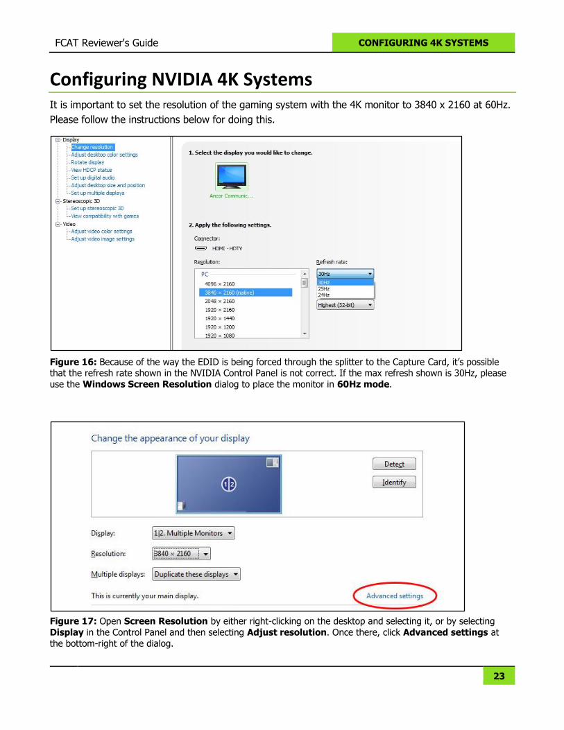
Configuring NVIDIA 4K Systems It is important to set the resolution of the gaming system with the 4K monitor to 3840 x 2160 at 60Hz.
Please follow the instructions below for doing this.
Figure 16: Because of the way the EDID is being forced through the splitter to the Capture Card, it’s possible that the refresh rate shown in the NVIDIA Control Panel is not correct. If the max refresh shown is 30Hz, please
use the Windows Screen Resolution dialog to place the monitor in 60Hz mode.
Figure 17: Open Screen Resolution by either right-clicking on the desktop and selecting it, or by selecting
Display in the Control Panel and then selecting Adjust resolution. Once there, click Advanced settings at
the bottom-right of the dialog.
FCAT Reviewer's Guide CONFIGURING 4K SYSTEMS
24
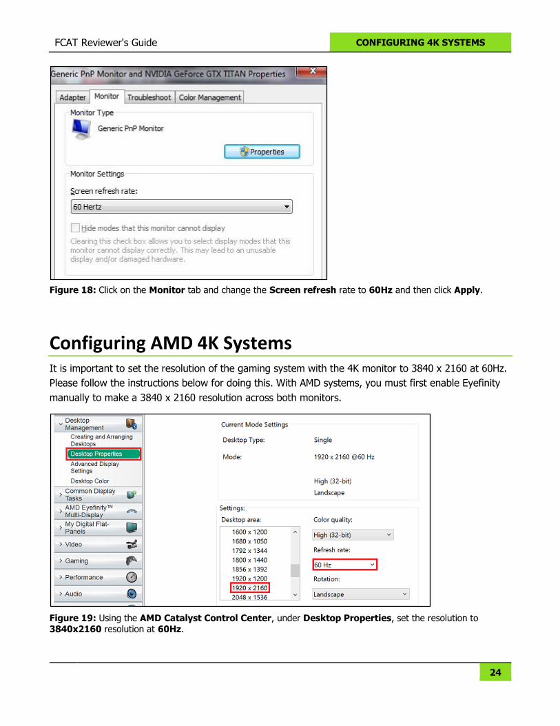
Figure 18: Click on the Monitor tab and change the Screen refresh rate to 60Hz and then click Apply.
Configuring AMD 4K Systems It is important to set the resolution of the gaming system with the 4K monitor to 3840 x 2160 at 60Hz.
Please follow the instructions below for doing this. With AMD systems, you must first enable Eyefinity
manually to make a 3840 x 2160 resolution across both monitors.
Figure 19: Using the AMD Catalyst Control Center, under Desktop Properties, set the resolution to 3840x2160 resolution at 60Hz.
FCAT Reviewer's Guide CONFIGURING 4K SYSTEMS
25
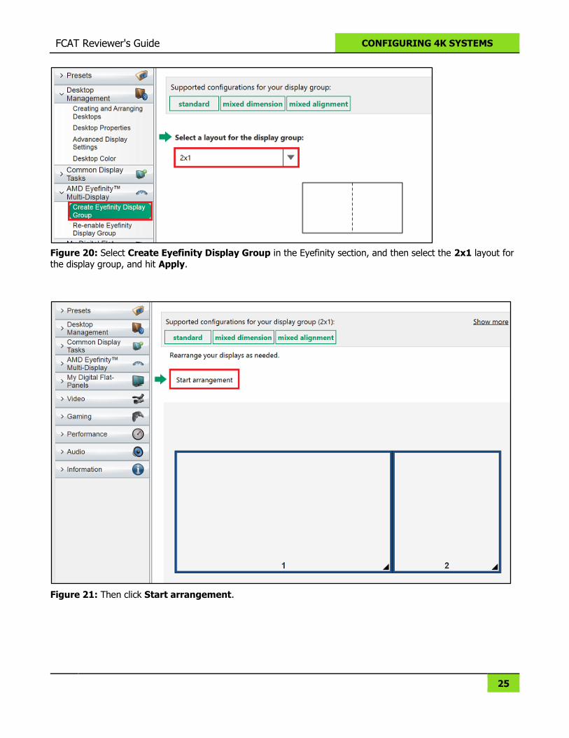
Figure 20: Select Create Eyefinity Display Group in the Eyefinity section, and then select the 2x1 layout for
the display group, and hit Apply.
Figure 21: Then click Start arrangement.
FCAT Reviewer's Guide CONFIGURING 4K SYSTEMS
26
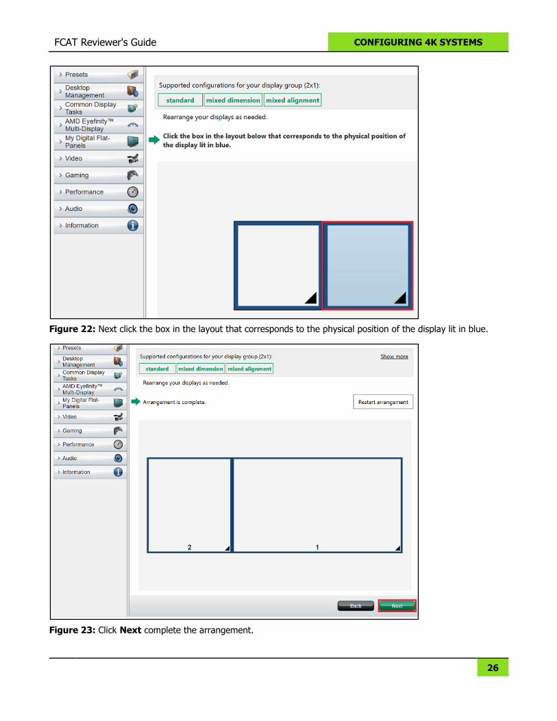
Figure 22: Next click the box in the layout that corresponds to the physical position of the display lit in blue.
Figure 23: Click Next complete the arrangement.
FCAT Reviewer's Guide CONFIGURING 4K SYSTEMS
27
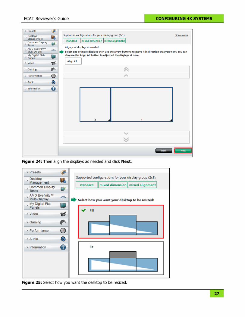
Figure 24: Then align the displays as needed and click Next.
Figure 25: Select how you want the desktop to be resized.
FCAT Reviewer's Guide CONFIGURING 4K SYSTEMS
28
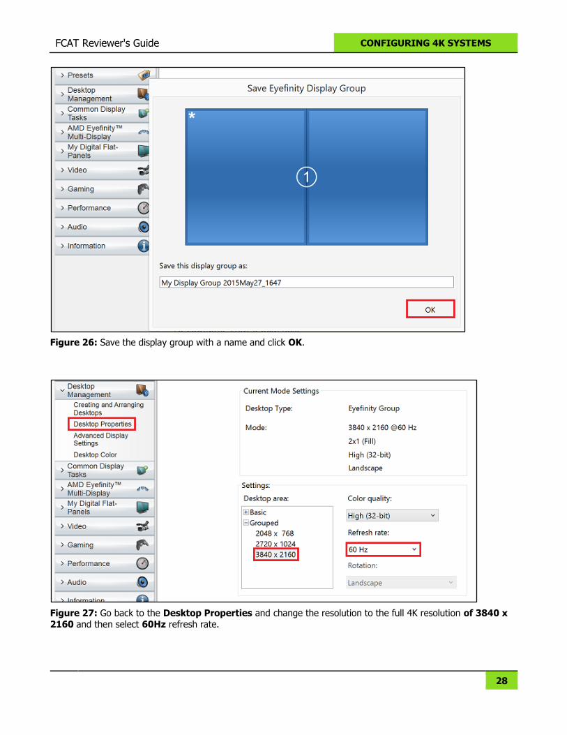
Figure 26: Save the display group with a name and click OK.
Figure 27: Go back to the Desktop Properties and change the resolution to the full 4K resolution of 3840 x
2160 and then select 60Hz refresh rate.
FCAT Reviewer's Guide CONFIGURING 4K SYSTEMS
29
Configuring the Vision Software
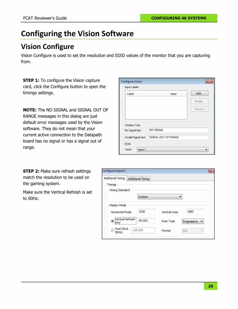
Vision Configure Vision Configure is used to set the resolution and EDID values of the monitor that you are capturing
from.
STEP 1: To configure the Vision capture
card, click the Configure button to open the
timings settings.
NOTE: The NO SIGNAL and SIGNAL OUT OF
RANGE messages in this dialog are just
default error messages used by the Vision
software. They do not mean that your
current active connection to the Datapath
board has no signal or has a signal out of
range.
STEP 2: Make sure refresh settings
match the resolution to be used on
the gaming system.
Make sure the Vertical Refresh is set
to 60Hz.
FCAT Reviewer's Guide CONFIGURING 4K SYSTEMS
30
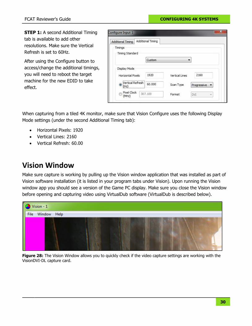
STEP 1: A second Additional Timing
tab is available to add other
resolutions. Make sure the Vertical
Refresh is set to 60Hz.
After using the Configure button to
access/change the additional timings,
you will need to reboot the target
machine for the new EDID to take
effect.
When capturing from a tiled 4K monitor, make sure that Vision Configure uses the following Display
Mode settings (under the second Additional Timing tab):
Horizontal Pixels: 1920
Vertical Lines: 2160
Vertical Refresh: 60.00
Vision Window Make sure capture is working by pulling up the Vision window application that was installed as part of
Vision software installation (it is listed in your program tabs under Vision). Upon running the Vision
window app you should see a version of the Game PC display. Make sure you close the Vision window
before opening and capturing video using VirtualDub software (VirtualDub is described below).
Figure 28: The Vision Window allows you to quickly check if the video capture settings are working with the VisionDVI-DL capture card.
31
OVERLAY | COLOR BARS FOR GAMES
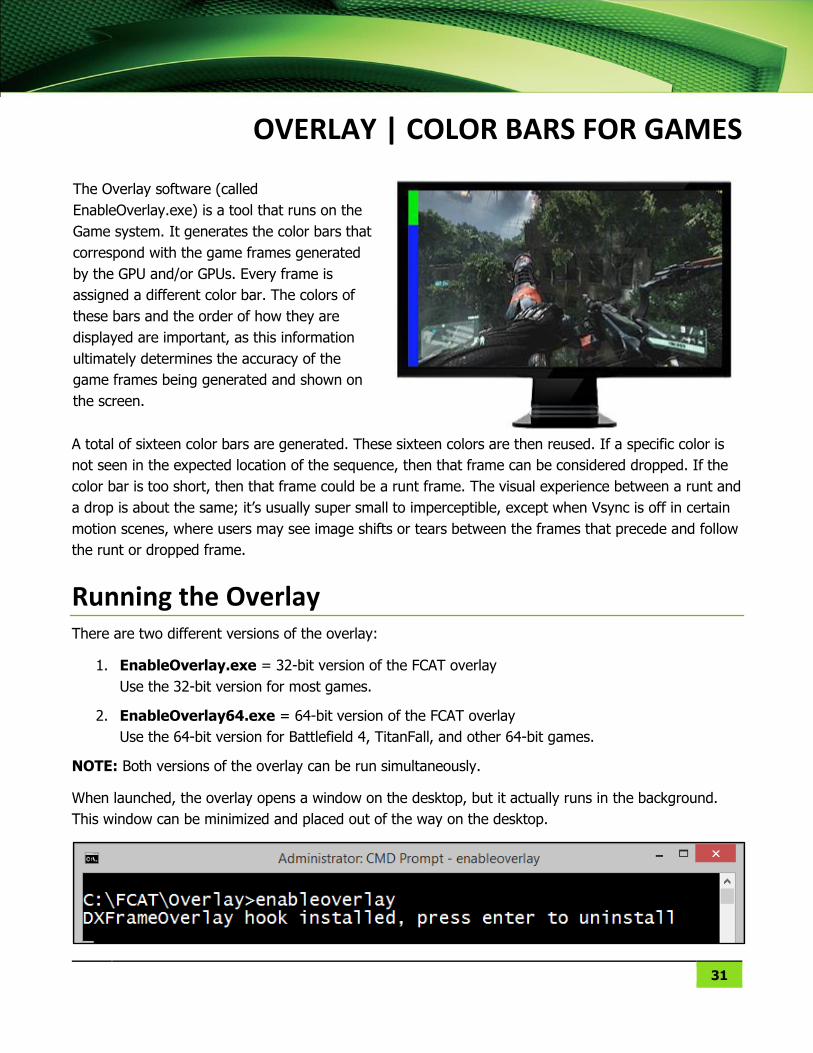
The Overlay software (called
EnableOverlay.exe) is a tool that runs on the
Game system. It generates the color bars that
correspond with the game frames generated
by the GPU and/or GPUs. Every frame is
assigned a different color bar. The colors of
these bars and the order of how they are
displayed are important, as this information
ultimately determines the accuracy of the
game frames being generated and shown on
the screen.
A total of sixteen color bars are generated. These sixteen colors are then reused. If a specific color is
not seen in the expected location of the sequence, then that frame can be considered dropped. If the
color bar is too short, then that frame could be a runt frame. The visual experience between a runt and
a drop is about the same; it’s usually super small to imperceptible, except when Vsync is off in certain
motion scenes, where users may see image shifts or tears between the frames that precede and follow
the runt or dropped frame.
Running the Overlay There are two different versions of the overlay:
1. EnableOverlay.exe = 32-bit version of the FCAT overlay
Use the 32-bit version for most games.
2. EnableOverlay64.exe = 64-bit version of the FCAT overlay
Use the 64-bit version for Battlefield 4, TitanFall, and other 64-bit games.
NOTE: Both versions of the overlay can be run simultaneously.
When launched, the overlay opens a window on the desktop, but it actually runs in the background.
This window can be minimized and placed out of the way on the desktop.
FCAT Reviewer's Guide OVERLAY | COLOR BARS FOR GAMES
32
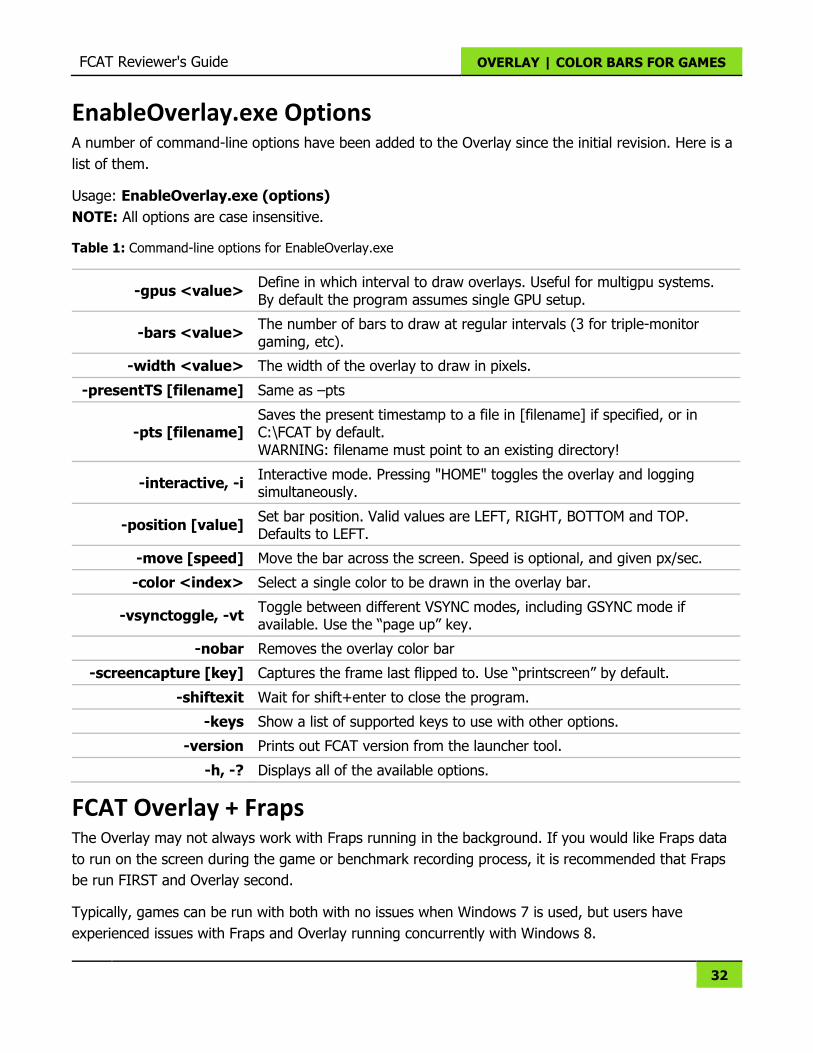
EnableOverlay.exe Options A number of command-line options have been added to the Overlay since the initial revision. Here is a
list of them.
Usage: EnableOverlay.exe (options)
NOTE: All options are case insensitive.
Table 1: Command-line options for EnableOverlay.exe
-gpus <value> Define in which interval to draw overlays. Useful for multigpu systems. By default the program assumes single GPU setup.
-bars <value> The number of bars to draw at regular intervals (3 for triple-monitor gaming, etc).
-width <value> The width of the overlay to draw in pixels.
-presentTS [filename] Same as –pts
-pts [filename] Saves the present timestamp to a file in [filename] if specified, or in C:\FCAT by default. WARNING: filename must point to an existing directory!
-interactive, -i Interactive mode. Pressing "HOME" toggles the overlay and logging simultaneously.
-position [value] Set bar position. Valid values are LEFT, RIGHT, BOTTOM and TOP. Defaults to LEFT.
-move [speed] Move the bar across the screen. Speed is optional, and given px/sec.
-color <index> Select a single color to be drawn in the overlay bar.
-vsynctoggle, -vt Toggle between different VSYNC modes, including GSYNC mode if available. Use the “page up” key.
-nobar Removes the overlay color bar
-screencapture [key] Captures the frame last flipped to. Use “printscreen” by default.
-shiftexit Wait for shift+enter to close the program.
-keys Show a list of supported keys to use with other options.
-version Prints out FCAT version from the launcher tool.
-h, -? Displays all of the available options.
FCAT Overlay + Fraps The Overlay may not always work with Fraps running in the background. If you would like Fraps data
to run on the screen during the game or benchmark recording process, it is recommended that Fraps
be run FIRST and Overlay second.
Typically, games can be run with both with no issues when Windows 7 is used, but users have
experienced issues with Fraps and Overlay running concurrently with Windows 8.
33
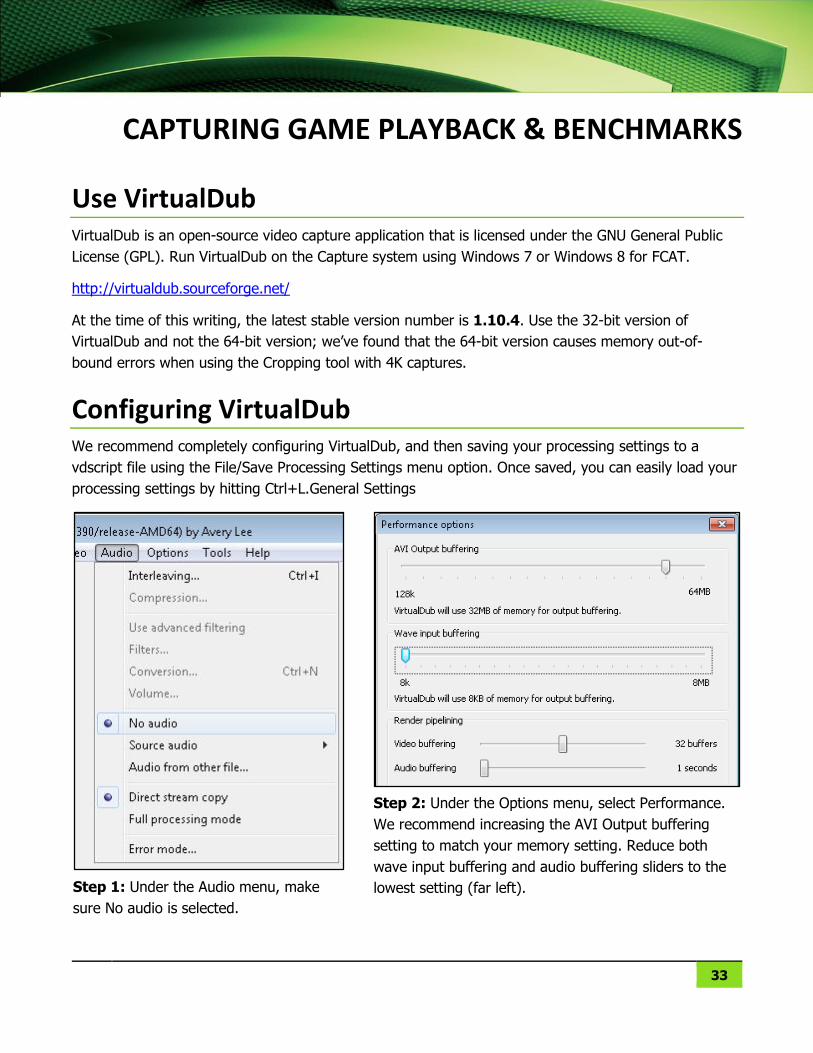
CAPTURING GAME PLAYBACK & BENCHMARKS
Use VirtualDub VirtualDub is an open-source video capture application that is licensed under the GNU General Public
License (GPL). Run VirtualDub on the Capture system using Windows 7 or Windows 8 for FCAT.
http://virtualdub.sourceforge.net/
At the time of this writing, the latest stable version number is 1.10.4. Use the 32-bit version of
VirtualDub and not the 64-bit version; we’ve found that the 64-bit version causes memory out-of-
bound errors when using the Cropping tool with 4K captures.
Configuring VirtualDub We recommend completely configuring VirtualDub, and then saving your processing settings to a
vdscript file using the File/Save Processing Settings menu option. Once saved, you can easily load your
processing settings by hitting Ctrl+L.General Settings
Step 1: Under the Audio menu, make
sure No audio is selected.
Step 2: Under the Options menu, select Performance.
We recommend increasing the AVI Output buffering
setting to match your memory setting. Reduce both
wave input buffering and audio buffering sliders to the
lowest setting (far left).
FCAT Reviewer's Guide CAPTURING GAME PLAYBACK & BENCHMARKS
34
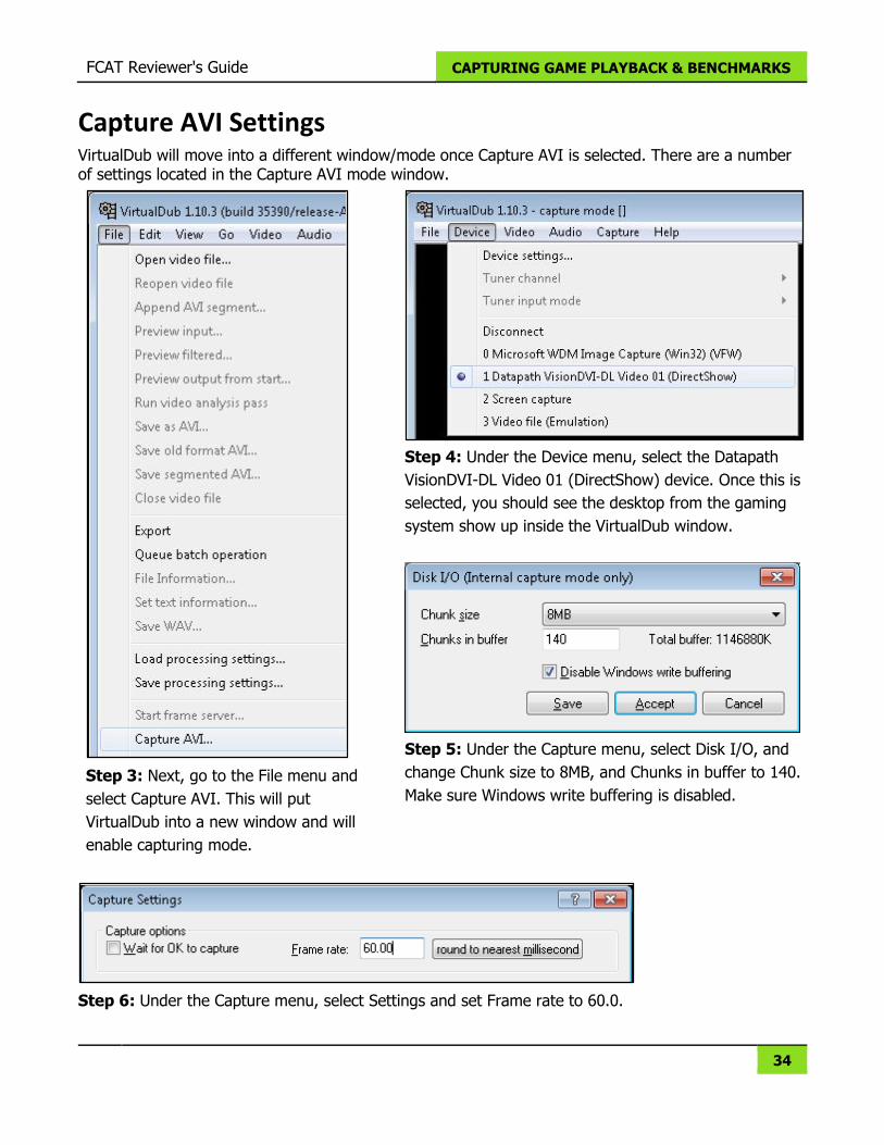
Capture AVI Settings VirtualDub will move into a different window/mode once Capture AVI is selected. There are a number of settings located in the Capture AVI mode window.
Step 3: Next, go to the File menu and
select Capture AVI. This will put
VirtualDub into a new window and will
enable capturing mode.
Step 4: Under the Device menu, select the Datapath
VisionDVI-DL Video 01 (DirectShow) device. Once this is
selected, you should see the desktop from the gaming
system show up inside the VirtualDub window.
Step 5: Under the Capture menu, select Disk I/O, and
change Chunk size to 8MB, and Chunks in buffer to 140.
Make sure Windows write buffering is disabled.
Step 6: Under the Capture menu, select Settings and set Frame rate to 60.0.
FCAT Reviewer's Guide CAPTURING GAME PLAYBACK & BENCHMARKS
35
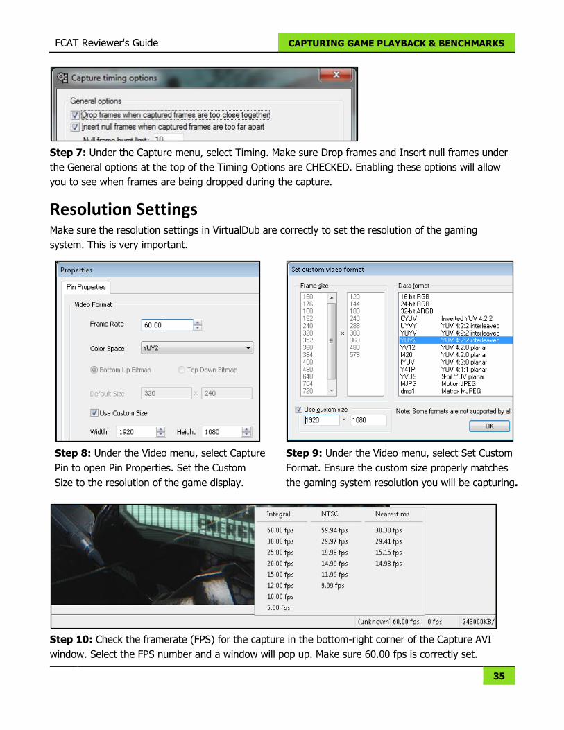
Step 7: Under the Capture menu, select Timing. Make sure Drop frames and Insert null frames under
the General options at the top of the Timing Options are CHECKED. Enabling these options will allow
you to see when frames are being dropped during the capture.
Resolution Settings Make sure the resolution settings in VirtualDub are correctly to set the resolution of the gaming
system. This is very important.
Step 8: Under the Video menu, select Capture
Pin to open Pin Properties. Set the Custom
Size to the resolution of the game display.
Step 9: Under the Video menu, select Set Custom
Format. Ensure the custom size properly matches
the gaming system resolution you will be capturing.
Step 10: Check the framerate (FPS) for the capture in the bottom-right corner of the Capture AVI
window. Select the FPS number and a window will pop up. Make sure 60.00 fps is correctly set.
FCAT Reviewer's Guide CAPTURING GAME PLAYBACK & BENCHMARKS
36
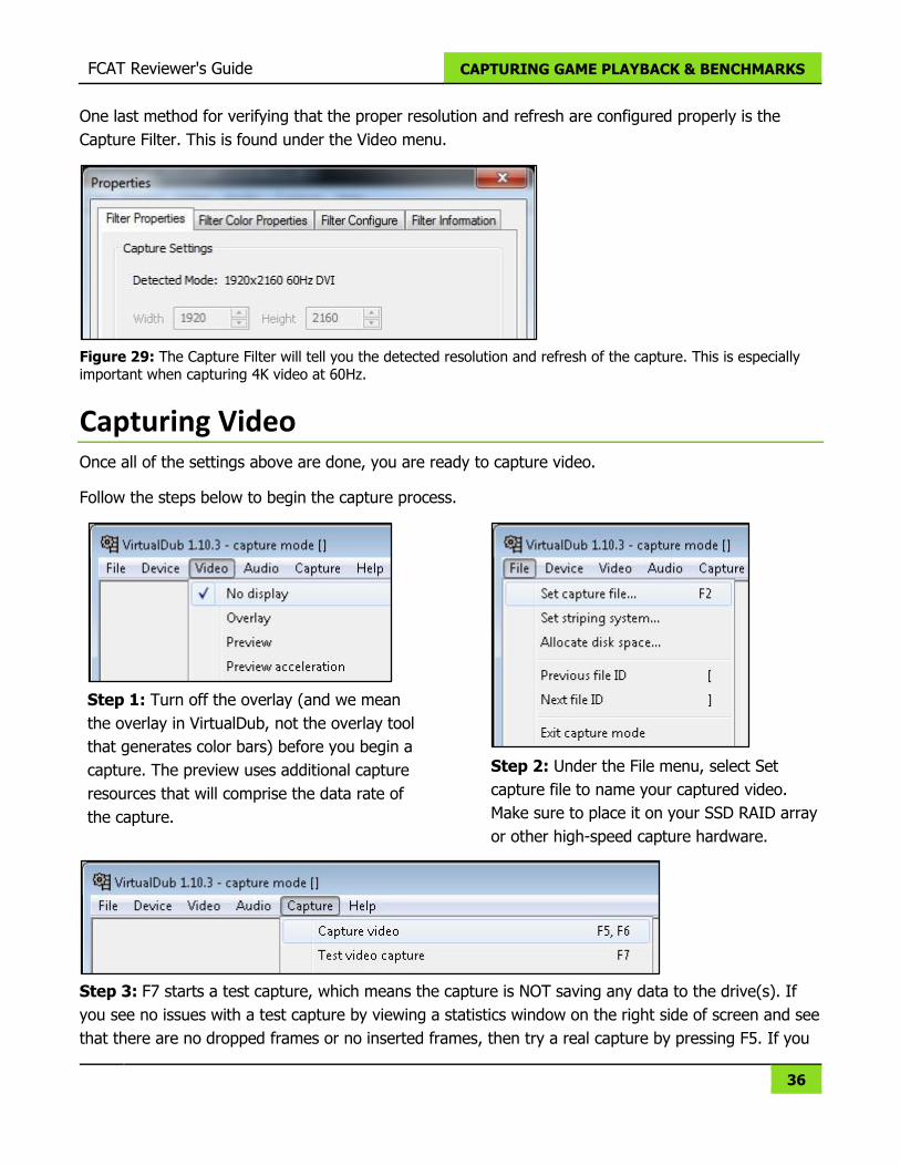
One last method for verifying that the proper resolution and refresh are configured properly is the
Capture Filter. This is found under the Video menu.
Figure 29: The Capture Filter will tell you the detected resolution and refresh of the capture. This is especially important when capturing 4K video at 60Hz.
Capturing Video Once all of the settings above are done, you are ready to capture video.
Follow the steps below to begin the capture process.
Step 1: Turn off the overlay (and we mean
the overlay in VirtualDub, not the overlay tool
that generates color bars) before you begin a
capture. The preview uses additional capture
resources that will comprise the data rate of
the capture.
Step 2: Under the File menu, select Set
capture file to name your captured video.
Make sure to place it on your SSD RAID array
or other high-speed capture hardware.
Step 3: F7 starts a test capture, which means the capture is NOT saving any data to the drive(s). If
you see no issues with a test capture by viewing a statistics window on the right side of screen and see
that there are no dropped frames or no inserted frames, then try a real capture by pressing F5. If you
FCAT Reviewer's Guide CAPTURING GAME PLAYBACK & BENCHMARKS
37
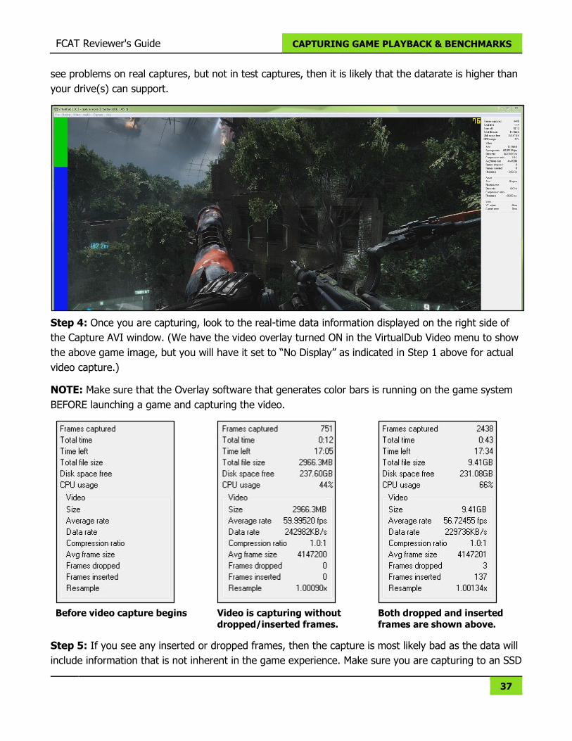
see problems on real captures, but not in test captures, then it is likely that the datarate is higher than
your drive(s) can support.
Step 4: Once you are capturing, look to the real-time data information displayed on the right side of
the Capture AVI window. (We have the video overlay turned ON in the VirtualDub Video menu to show
the above game image, but you will have it set to “No Display” as indicated in Step 1 above for actual
video capture.)
NOTE: Make sure that the Overlay software that generates color bars is running on the game system
BEFORE launching a game and capturing the video.
Before video capture begins
Video is capturing without
dropped/inserted frames.
Both dropped and inserted
frames are shown above.
Step 5: If you see any inserted or dropped frames, then the capture is most likely bad as the data will
include information that is not inherent in the game experience. Make sure you are capturing to an SSD
FCAT Reviewer's Guide CAPTURING GAME PLAYBACK & BENCHMARKS
38
RAID array or other high-speed storage device to try to overcome these issues, or try capturing at a
lower resolution if still getting dropped or inserted frames.
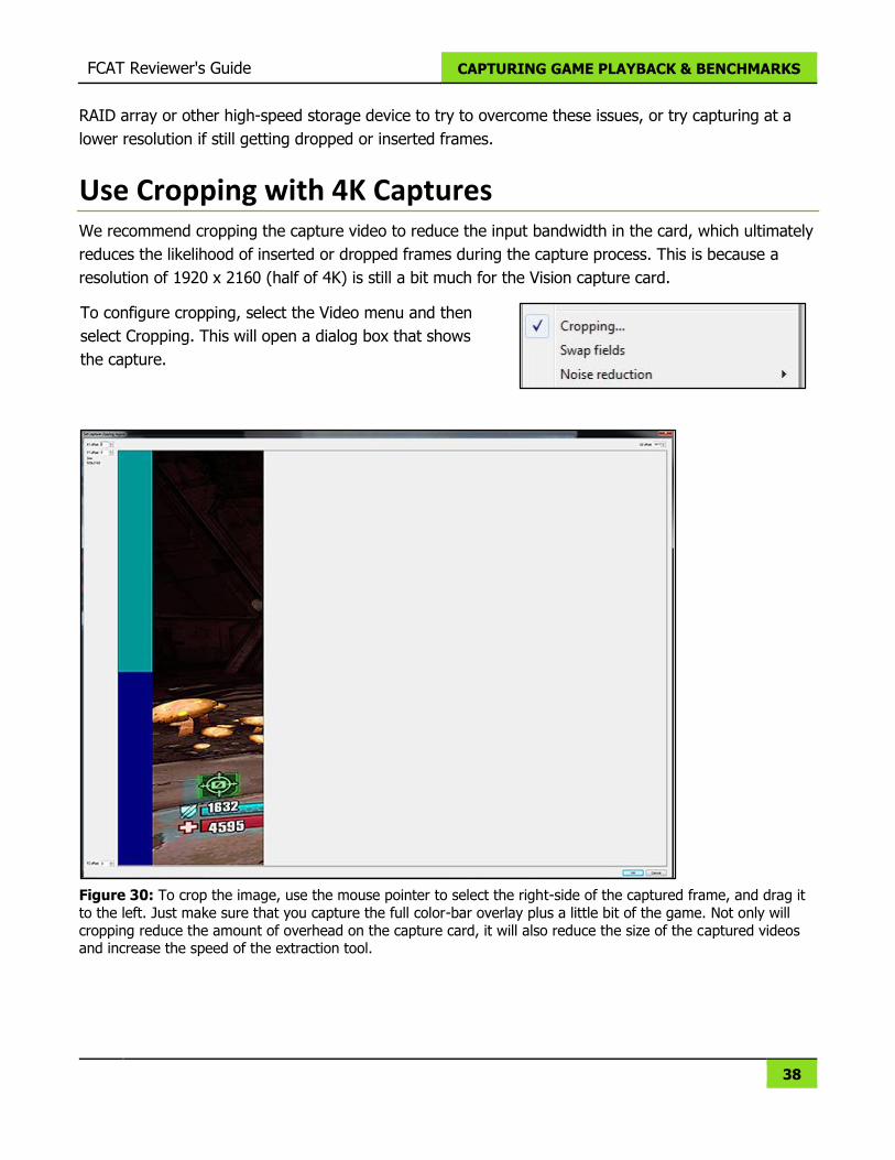
Use Cropping with 4K Captures We recommend cropping the capture video to reduce the input bandwidth in the card, which ultimately
reduces the likelihood of inserted or dropped frames during the capture process. This is because a
resolution of 1920 x 2160 (half of 4K) is still a bit much for the Vision capture card.
To configure cropping, select the Video menu and then
select Cropping. This will open a dialog box that shows
the capture.
Figure 30: To crop the image, use the mouse pointer to select the right-side of the captured frame, and drag it
to the left. Just make sure that you capture the full color-bar overlay plus a little bit of the game. Not only will
cropping reduce the amount of overhead on the capture card, it will also reduce the size of the captured videos and increase the speed of the extraction tool.

FCAT Reviewer's Guide CAPTURING GAME PLAYBACK & BENCHMARKS
39
Video Playback & Testing It’s always a good idea to open your captured game video in VirtualDub to look for dropped and
inserted frames.
STEP 1: You will need to Exit Capture Mode first in order to see the captured video file on your
capture disk. Do this under the File menu.
STEP 2: Once back in the main screen, select Open video file, and browse to the captured video.
STEP 3: Once open, you can step through the video using the controls at the bottom-left.
FCAT Reviewer's Guide CAPTURING GAME PLAYBACK & BENCHMARKS
40
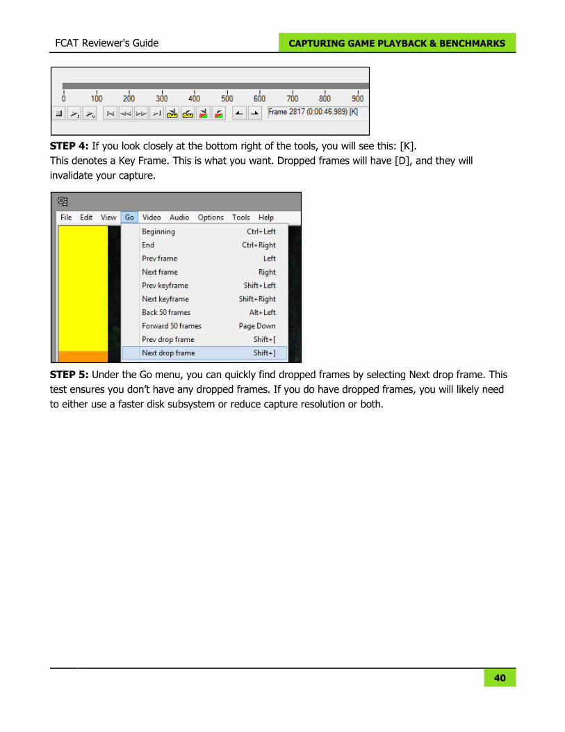
STEP 4: If you look closely at the bottom right of the tools, you will see this: [K].
This denotes a Key Frame. This is what you want. Dropped frames will have [D], and they will
invalidate your capture.
STEP 5: Under the Go menu, you can quickly find dropped frames by selecting Next drop frame. This
test ensures you don’t have any dropped frames. If you do have dropped frames, you will likely need
to either use a faster disk subsystem or reduce capture resolution or both.
41
EXTRACTOR | POST VIDEO PROCESSING
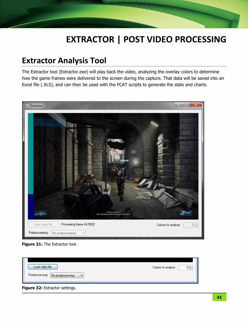
Extractor Analysis Tool The Extractor tool (Extractor.exe) will play back the video, analyzing the overlay colors to determine
how the game frames were delivered to the screen during the capture. That data will be saved into an
Excel file (.XLS), and can then be used with the FCAT scripts to generate the stats and charts.
Figure 31: The Extractor tool.
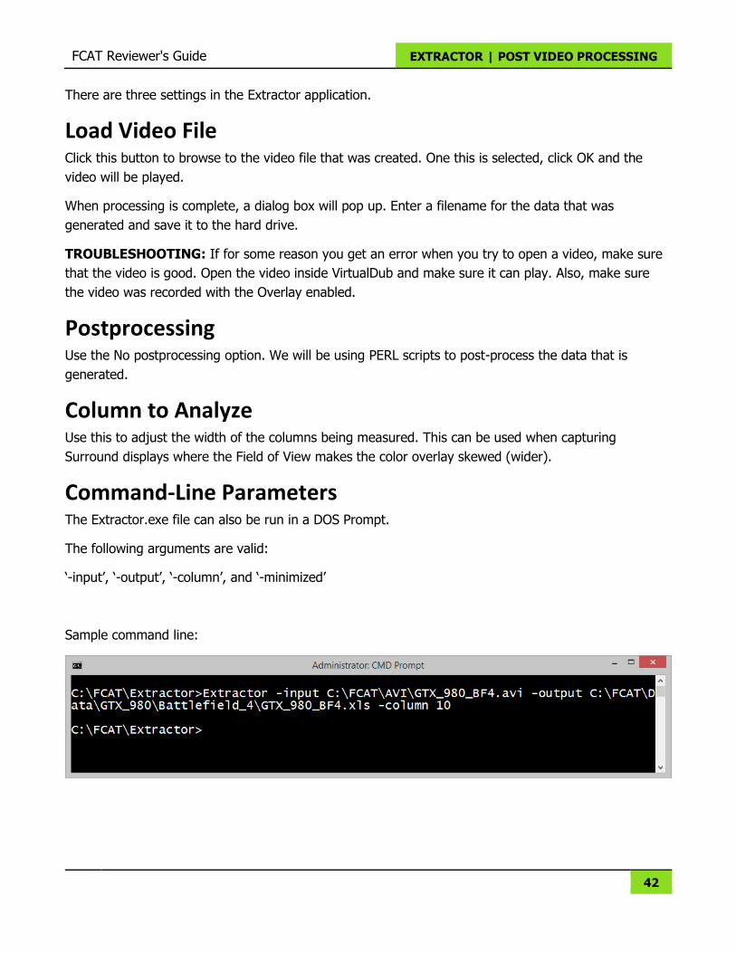
Figure 32: Extractor settings.
FCAT Reviewer's Guide EXTRACTOR | POST VIDEO PROCESSING
42
There are three settings in the Extractor application.
Load Video File Click this button to browse to the video file that was created. One this is selected, click OK and the
video will be played.
When processing is complete, a dialog box will pop up. Enter a filename for the data that was
generated and save it to the hard drive.
TROUBLESHOOTING: If for some reason you get an error when you try to open a video, make sure
that the video is good. Open the video inside VirtualDub and make sure it can play. Also, make sure
the video was recorded with the Overlay enabled.
Postprocessing Use the No postprocessing option. We will be using PERL scripts to post-process the data that is
generated.
Column to Analyze Use this to adjust the width of the columns being measured. This can be used when capturing
Surround displays where the Field of View makes the color overlay skewed (wider).
Command-Line Parameters The Extractor.exe file can also be run in a DOS Prompt.
The following arguments are valid:
‘-input’, ‘-output’, ‘-column’, and ‘-minimized’
Sample command line:
43
FCAT SCRIPTS | CREATING CHARTS & TABLES
The FCAT scripts are written with PERL. As such, a few applications including Strawberry Perl and GNU
Plot are needed.
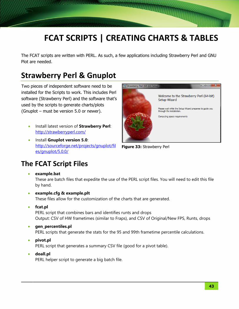
Strawberry Perl & Gnuplot Two pieces of independent software need to be
installed for the Scripts to work. This includes Perl
software (Strawberry Perl) and the software that’s
used by the scripts to generate charts/plots
(Gnuplot – must be version 5.0 or newer).
Install latest version of Strawberry Perl:
http://strawberryperl.com/
Install Gnuplot version 5.0:
http://sourceforge.net/projects/gnuplot/fil
es/gnuplot/5.0.0/
Figure 33: Strawberry Perl
The FCAT Script Files example.bat
These are batch files that expedite the use of the PERL script files. You will need to edit this file
by hand.
example.cfg & example.plt
These files allow for the customization of the charts that are generated.
fcat.pl
PERL script that combines bars and identifies runts and drops
Output: CSV of HW frametimes (similar to Fraps), and CSV of Original/New FPS, Runts, drops
gen_percentiles.pl
PERL scripts that generate the stats for the 95 and 99th frametime percentile calculations.
pivot.pl
PERL script that generates a summary CSV file (good for a pivot table).
doall.pl
PERL helper script to generate a big batch file.
FCAT Reviewer's Guide FCAT SCRIPTS | CREATING CHARTS & TABLES
44
Directory Structure Follow these three steps to extract the FCAT Tools and to create the proper directory structure for the
FCAT scripts on your capture system.
STEP 1 | Unpack the FCAT Tools
The FCAT Tools will be delivered in a ZIP file. Uncompress this
ZIP file to your C:\ drive, creating the directory C:\FCAT.
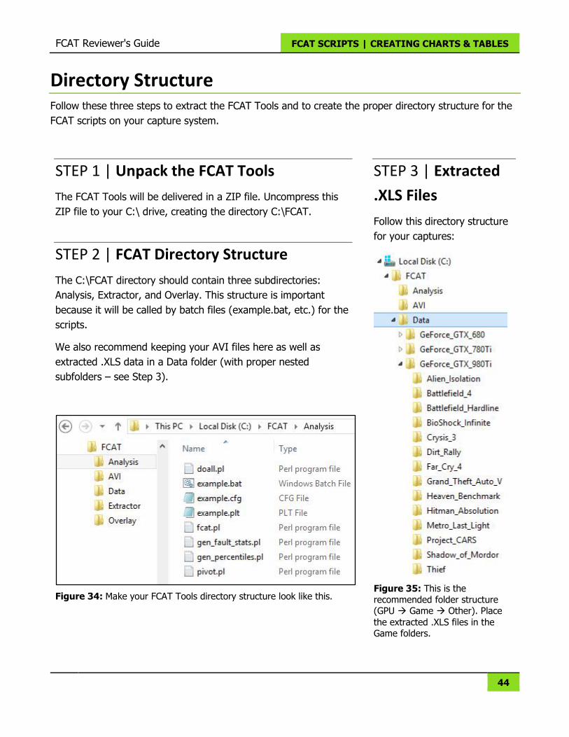
STEP 2 | FCAT Directory Structure
The C:\FCAT directory should contain three subdirectories:
Analysis, Extractor, and Overlay. This structure is important
because it will be called by batch files (example.bat, etc.) for the
scripts.
We also recommend keeping your AVI files here as well as
extracted .XLS data in a Data folder (with proper nested
subfolders – see Step 3).
Figure 34: Make your FCAT Tools directory structure look like this.
STEP 3 | Extracted
.XLS Files
Follow this directory structure
for your captures:
Figure 35: This is the recommended folder structure (GPU Game Other). Place
the extracted .XLS files in the Game folders.
FCAT Reviewer's Guide FCAT SCRIPTS | CREATING CHARTS & TABLES
45
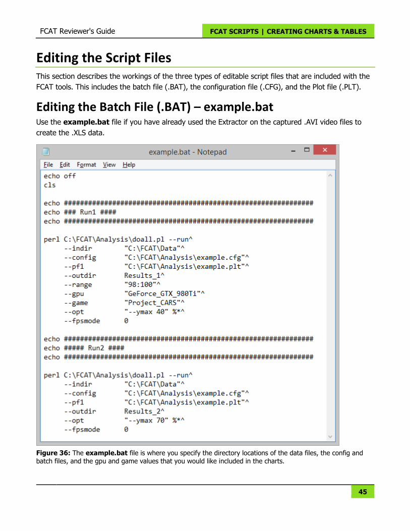
Editing the Script Files This section describes the workings of the three types of editable script files that are included with the
FCAT tools. This includes the batch file (.BAT), the configuration file (.CFG), and the Plot file (.PLT).
Editing the Batch File (.BAT) – example.bat Use the example.bat file if you have already used the Extractor on the captured .AVI video files to
create the .XLS data.
Figure 36: The example.bat file is where you specify the directory locations of the data files, the config and
batch files, and the gpu and game values that you would like included in the charts.

FCAT Reviewer's Guide FCAT SCRIPTS | CREATING CHARTS & TABLES
46
Table 2: Parameters for the example.bat file.
perl
This is the full path to the doall.pl file.
Adding parameters after this path does different things:
--run: Creates and then automatically runs the run_fcat.bat file that is created in the
outdir folder.
--extract: Runs the Extractor.exe file on the captured .AVI video files, and then
creates the run_fcat.bat file in the specified outdir folder.
--run --extract: Both of these can be used together.
--tooldir This parameter must include a full path that points to the FCAT directory
--indir
This parameter must include a full path that points to the Data folder where the
extracted .XLS files are located.
The path should only go as deep as the Data folder (C:\FCAT\Data).
--config This parameter must include a full path that points to the folder that contains
the .CFG file (example.cfg).
NOTE: If you change the name of the .CFG file, change it here to match.
--pf1 This parameter must include a full path that points to the folder that contains
the .PF1 file (example.pf1).
NOTE: If you change the name of the .CFG file, change it here to match.
--outdir This is the name of the folder that is created with the final charts and table data. So
if Results_1 is used, then a folder will be created like this: C:\FCAT\Analysis\Results_1
--range This parameter controls the X-axis range in Percentile chart. Setting this to 98:100
will make the X-axis start at 98 and end at 100.
--gpu
This parameter allows you to ONLY analyze data for a given GPU.
Include these lines for each GPU that you want to show data for, or remove the GPU
lines altogether to display data for all GPUs.
NOTE: Make sure that GPU directory names match the names used here. This includes
matching lower- and upper-case characters.
--game
This parameter allows you to ONLY analyze data for a given game.
Include these lines for each game that you want to show data for, or remove the
game lines altogether to display data for all games.
NOTE: Make sure that game directory names match the names used here. This
includes matching lower- and upper-case characters.
--opt Set your Y-axis height here. Removing this parameter will set the Y-axis to the
maximum value in the chart. This is a good way of seeing subtleties in a chart that
can be lost when the Y-axis is too large.
FCAT Reviewer's Guide FCAT SCRIPTS | CREATING CHARTS & TABLES
47
--fpsmode A setting of 0 will generate Frame Time information in the charts.
A setting of 1 will generate FPS information in the charts.
^ The caret (inverted V-shaped symbol) MUST be used at the end of every line except
for the last line in the batch (.BAT) file.
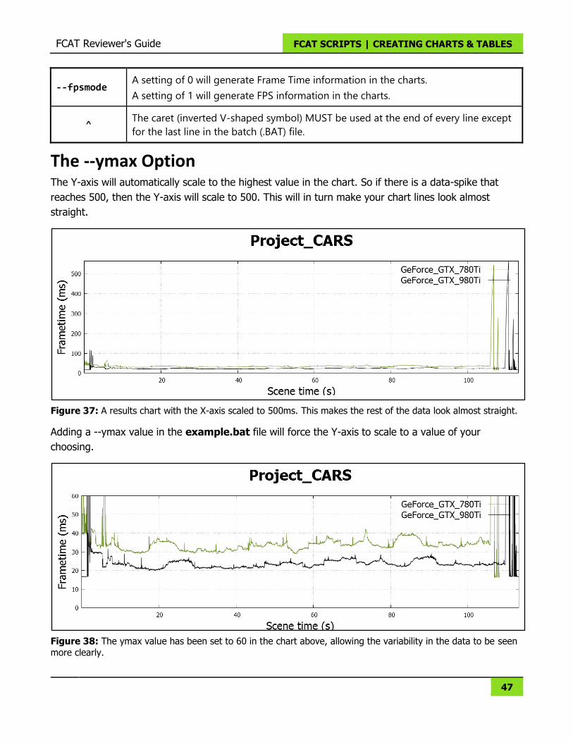
The --ymax Option The Y-axis will automatically scale to the highest value in the chart. So if there is a data-spike that
reaches 500, then the Y-axis will scale to 500. This will in turn make your chart lines look almost
straight.
Figure 37: A results chart with the X-axis scaled to 500ms. This makes the rest of the data look almost straight.
Adding a --ymax value in the example.bat file will force the Y-axis to scale to a value of your
choosing.
Figure 38: The ymax value has been set to 60 in the chart above, allowing the variability in the data to be seen
more clearly.
FCAT Reviewer's Guide FCAT SCRIPTS | CREATING CHARTS & TABLES
48
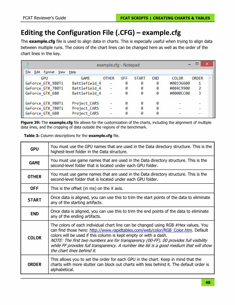
Editing the Configuration File (.CFG) – example.cfg The example.cfg file is used to align data in charts. This is especially useful when trying to align data
between multiple runs. The colors of the chart lines can be changed here as well as the order of the
chart lines in the key.
Figure 39: The example.cfg file allows for the customization of the charts, including the alignment of multiple data lines, and the cropping of data outside the regions of the benchmark.
Table 3: Column descriptions for the example.cfg file.
GPU You must use the GPU names that are used in the Data directory structure. This is the highest-level folder in the Data structure.
GAME You must use game names that are used in the Data directory structure. This is the second-level folder that is located under each GPU folder.
OTHER You must use game names that are used in the Data directory structure. This is the second-level folder that is located under each GPU folder.
OFF This is the offset (in ms) on the X axis.
START Once data is aligned, you can use this to trim the start points of the data to eliminate any of the starting artifacts.
END Once data is aligned, you can use this to trim the end points of the data to eliminate any of the ending artifacts.
COLOR
The colors of each individual chart line can be changed using RGB #Hex values. You can find those here: http://www.rapidtables.com/web/color/RGB_Color.htm. Default colors will be used if this column is kept empty or with a dash. NOTE: The first two numbers are for transparency (00-FF). 00 provides full visibility while FF provides full transparency. A number like 66 is a good medium that will show the chart lines behind it.
ORDER This allows you to set the order for each GPU in the chart. Keep in mind that the charts with more stutter can block out charts with less behind it. The default order is alphabetical.
FCAT Reviewer's Guide FCAT SCRIPTS | CREATING CHARTS & TABLES
49
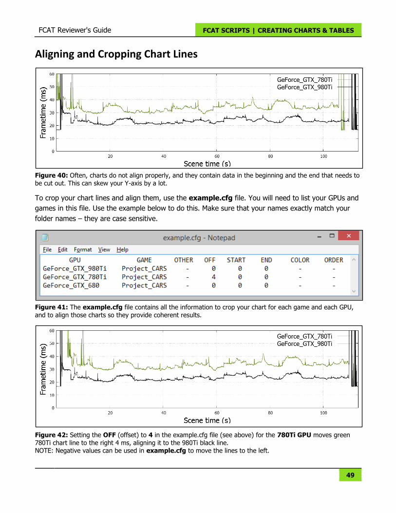
Aligning and Cropping Chart Lines
Figure 40: Often, charts do not align properly, and they contain data in the beginning and the end that needs to
be cut out. This can skew your Y-axis by a lot.
To crop your chart lines and align them, use the example.cfg file. You will need to list your GPUs and
games in this file. Use the example below to do this. Make sure that your names exactly match your
folder names – they are case sensitive.
Figure 41: The example.cfg file contains all the information to crop your chart for each game and each GPU,
and to align those charts so they provide coherent results.
Figure 42: Setting the OFF (offset) to 4 in the example.cfg file (see above) for the 780Ti GPU moves green
780Ti chart line to the right 4 ms, aligning it to the 980Ti black line. NOTE: Negative values can be used in example.cfg to move the lines to the left.
FCAT Reviewer's Guide FCAT SCRIPTS | CREATING CHARTS & TABLES
50
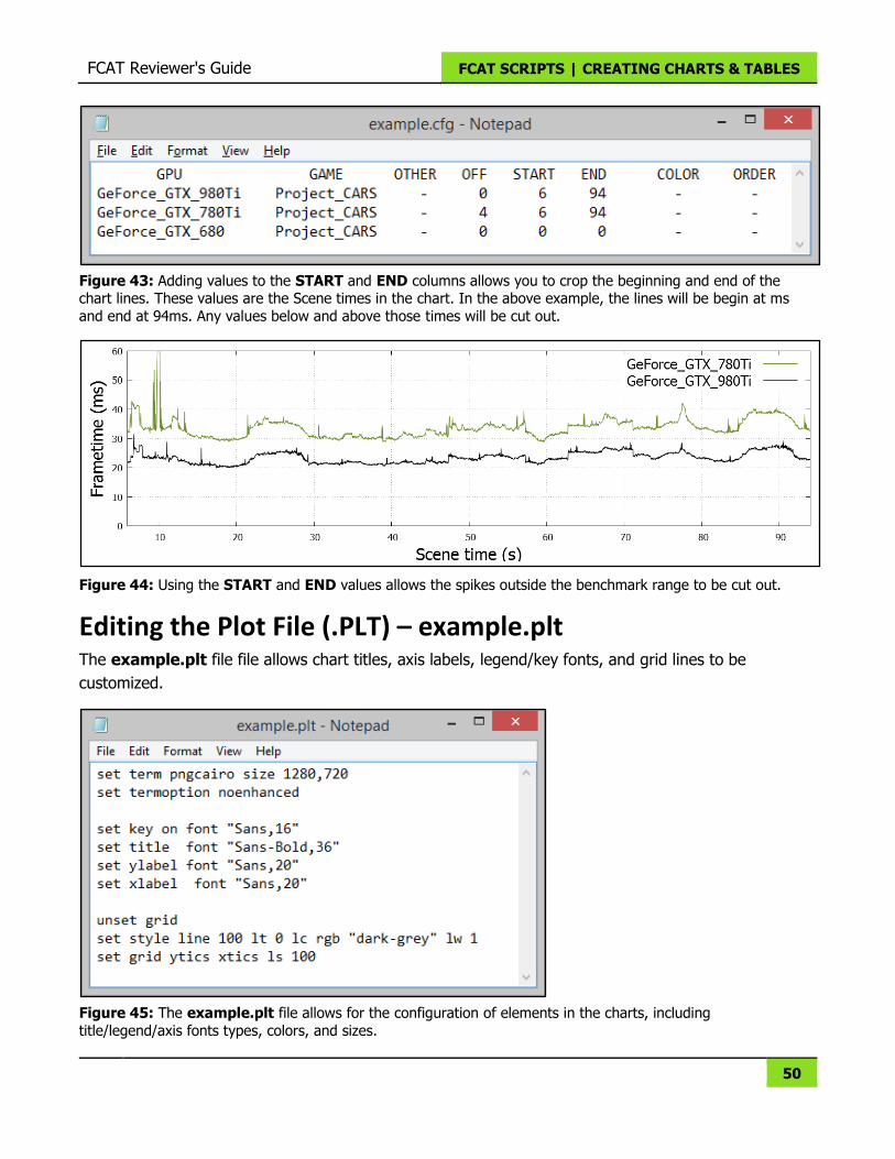
Figure 43: Adding values to the START and END columns allows you to crop the beginning and end of the chart lines. These values are the Scene times in the chart. In the above example, the lines will be begin at ms
and end at 94ms. Any values below and above those times will be cut out.
Figure 44: Using the START and END values allows the spikes outside the benchmark range to be cut out.
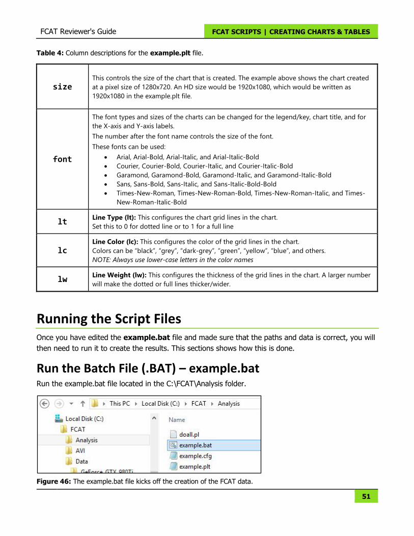
Editing the Plot File (.PLT) – example.plt The example.plt file file allows chart titles, axis labels, legend/key fonts, and grid lines to be
customized.
Figure 45: The example.plt file allows for the configuration of elements in the charts, including
title/legend/axis fonts types, colors, and sizes.
FCAT Reviewer's Guide FCAT SCRIPTS | CREATING CHARTS & TABLES
51
Table 4: Column descriptions for the example.plt file.
size This controls the size of the chart that is created. The example above shows the chart created
at a pixel size of 1280x720. An HD size would be 1920x1080, which would be written as
1920x1080 in the example.plt file.
font
The font types and sizes of the charts can be changed for the legend/key, chart title, and for
the X-axis and Y-axis labels.
The number after the font name controls the size of the font.
These fonts can be used:
Arial, Arial-Bold, Arial-Italic, and Arial-Italic-Bold
Courier, Courier-Bold, Courier-Italic, and Courier-Italic-Bold
Garamond, Garamond-Bold, Garamond-Italic, and Garamond-Italic-Bold
Sans, Sans-Bold, Sans-Italic, and Sans-Italic-Bold-Bold
Times-New-Roman, Times-New-Roman-Bold, Times-New-Roman-Italic, and Times-
New-Roman-Italic-Bold
lt Line Type (lt): This configures the chart grid lines in the chart.
Set this to 0 for dotted line or to 1 for a full line
lc Line Color (lc): This configures the color of the grid lines in the chart.
Colors can be “black”, “grey”, “dark-grey”, “green”, “yellow”, “blue”, and others.
NOTE: Always use lower-case letters in the color names
lw Line Weight (lw): This configures the thickness of the grid lines in the chart. A larger number
will make the dotted or full lines thicker/wider.
Running the Script Files Once you have edited the example.bat file and made sure that the paths and data is correct, you will
then need to run it to create the results. This sections shows how this is done.
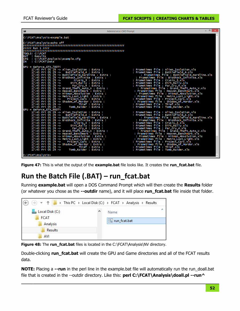
Run the Batch File (.BAT) – example.bat Run the example.bat file located in the C:\FCAT\Analysis folder.
Figure 46: The example.bat file kicks off the creation of the FCAT data.
FCAT Reviewer's Guide FCAT SCRIPTS | CREATING CHARTS & TABLES
52
Figure 47: This is what the output of the example.bat file looks like. It creates the run_fcat.bat file.
Run the Batch File (.BAT) – run_fcat.bat Running example.bat will open a DOS Command Prompt which will then create the Results folder
(or whatever you chose as the --outdir name), and it will place run_fcat.bat file inside that folder.
Figure 48: The run_fcat.bat files is located in the C:\FCAT\Analysis\NV directory.
Double-clicking run_fcat.bat will create the GPU and Game directories and all of the FCAT results
data.
NOTE: Placing a --run in the perl line in the example.bat file will automatically run the run_doall.bat
file that is created in the --outdir directory. Like this: perl C:\FCAT\Analysis\doall.pl --run^
FCAT Reviewer's Guide FCAT SCRIPTS | CREATING CHARTS & TABLES
53
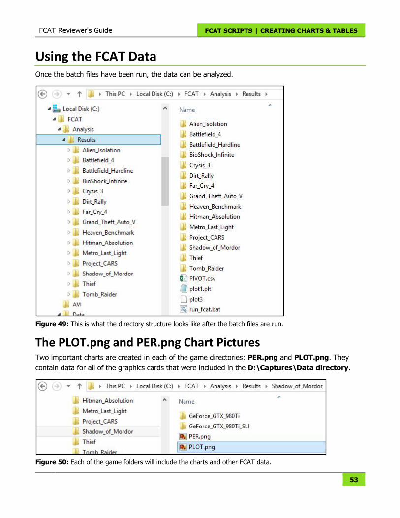
Using the FCAT Data Once the batch files have been run, the data can be analyzed.
Figure 49: This is what the directory structure looks like after the batch files are run.
The PLOT.png and PER.png Chart Pictures Two important charts are created in each of the game directories: PER.png and PLOT.png. They
contain data for all of the graphics cards that were included in the D:\Captures\Data directory.
Figure 50: Each of the game folders will include the charts and other FCAT data.
FCAT Reviewer's Guide FCAT SCRIPTS | CREATING CHARTS & TABLES
54
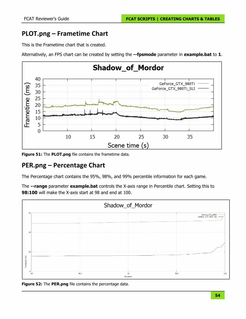
PLOT.png – Frametime Chart
This is the Frametime chart that is created.
Alternatively, an FPS chart can be created by setting the --fpsmode parameter in example.bat to 1.
Figure 51: The PLOT.png file contains the frametime data.
PER.png – Percentage Chart
The Percentage chart contains the 95%, 98%, and 99% percentile information for each game.
The --range parameter example.bat controls the X-axis range in Percentile chart. Setting this to
98:100 will make the X-axis start at 98 and end at 100.
Figure 52: The PER.png file contains the percentage data.
FCAT Reviewer's Guide FCAT SCRIPTS | CREATING CHARTS & TABLES
55
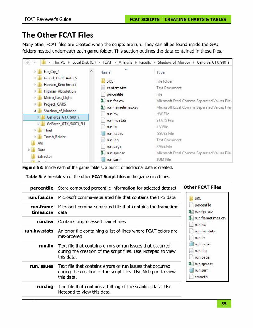
The Other FCAT Files Many other FCAT files are created when the scripts are run. They can all be found inside the GPU
folders nested underneath each game folder. This section outlines the data contained in these files.
Figure 53: Inside each of the game folders, a bunch of additional data is created.
Table 5: A breakdown of the other FCAT Script files in the game directories.
percentile Store computed percentile information for selected dataset Other FCAT Files
run.fps.csv Microsoft comma-separated file that contains the FPS data
run.frame times.csv
Microsoft comma-separated file that contains the frametime data
run.hw Contains unprocessed frametimes
run.hw.stats An error file containing a list of lines where FCAT colors are mis-ordered
run.ilv Text file that contains errors or run issues that occurred during the creation of the script files. Use Notepad to view this data.
run.issues Text file that contains errors or run issues that occurred during the creation of the script files. Use Notepad to view this data.
run.log Text file that contains a full log of the scanline data. Use Notepad to view this data.
FCAT Reviewer's Guide FCAT SCRIPTS | CREATING CHARTS & TABLES
56
run.sps.csv Microsoft comma-separated file that contains information including time, HWFPS (calculated FPS), droped frames, run frames, and raw FPS (original FPS).
run.sum Text file that contains calculated FPS, original FPS, calculated frames (true/runts/drops), and number of frames and time. Use Notepad to view this file.
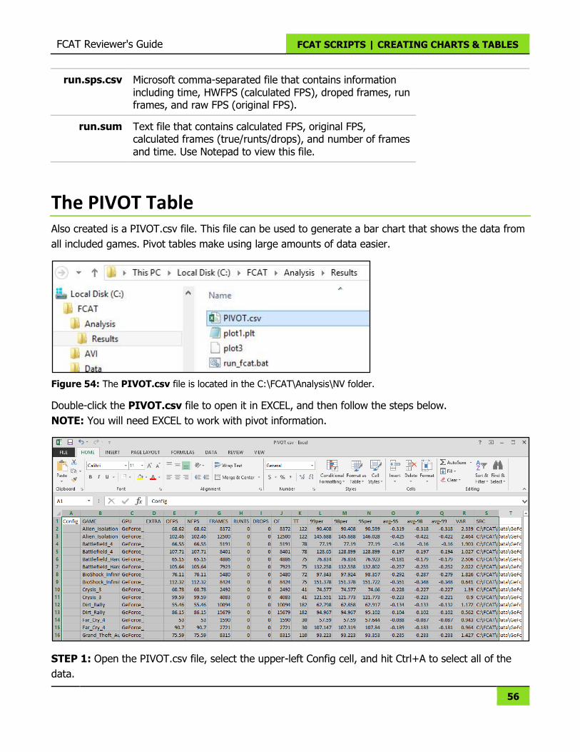
The PIVOT Table Also created is a PIVOT.csv file. This file can be used to generate a bar chart that shows the data from
all included games. Pivot tables make using large amounts of data easier.
Figure 54: The PIVOT.csv file is located in the C:\FCAT\Analysis\NV folder.
Double-click the PIVOT.csv file to open it in EXCEL, and then follow the steps below.
NOTE: You will need EXCEL to work with pivot information.
STEP 1: Open the PIVOT.csv file, select the upper-left Config cell, and hit Ctrl+A to select all of the
data.
FCAT Reviewer's Guide FCAT SCRIPTS | CREATING CHARTS & TABLES
57
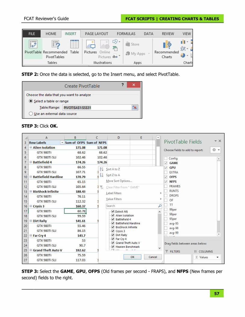
STEP 2: Once the data is selected, go to the Insert menu, and select PivotTable.
STEP 3: Click OK.
STEP 3: Select the GAME, GPU, OFPS (Old frames per second - FRAPS), and NFPS (New frames per
second) fields to the right.
FCAT Reviewer's Guide FCAT SCRIPTS | CREATING CHARTS & TABLES
58
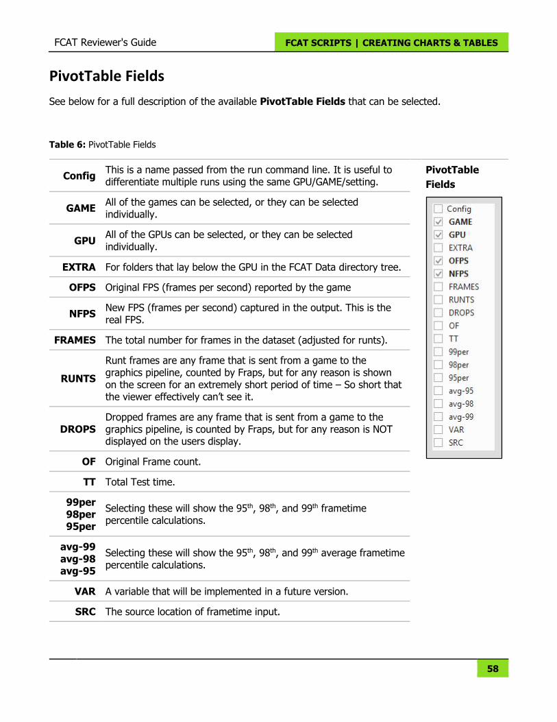
PivotTable Fields
See below for a full description of the available PivotTable Fields that can be selected.
Table 6: PivotTable Fields
Config This is a name passed from the run command line. It is useful to differentiate multiple runs using the same GPU/GAME/setting.
PivotTable
Fields
GAME All of the games can be selected, or they can be selected individually.
GPU All of the GPUs can be selected, or they can be selected individually.
EXTRA For folders that lay below the GPU in the FCAT Data directory tree.
OFPS Original FPS (frames per second) reported by the game
NFPS New FPS (frames per second) captured in the output. This is the real FPS.
FRAMES The total number for frames in the dataset (adjusted for runts).
RUNTS
Runt frames are any frame that is sent from a game to the graphics pipeline, counted by Fraps, but for any reason is shown on the screen for an extremely short period of time – So short that the viewer effectively can’t see it.
DROPS Dropped frames are any frame that is sent from a game to the graphics pipeline, is counted by Fraps, but for any reason is NOT displayed on the users display.
OF Original Frame count.
TT Total Test time.
99per 98per 95per
Selecting these will show the 95th, 98th, and 99th frametime percentile calculations.
avg-99 avg-98 avg-95
Selecting these will show the 95th, 98th, and 99th average frametime percentile calculations.
VAR A variable that will be implemented in a future version.
SRC The source location of frametime input.
FCAT Reviewer's Guide FCAT SCRIPTS | CREATING CHARTS & TABLES
59
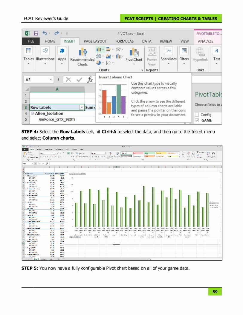
STEP 4: Select the Row Labels cell, hit Ctrl+A to select the data, and then go to the Insert menu
and select Column charts.
STEP 5: You now have a fully configurable Pivot chart based on all of your game data.
60
MISCELLANEOUS INFORMATION
The Gefen splitter is not required on NVIDIA-based GPUs, even when multiple GPUs are used in SLI
mode.
NVIDIA Clone Mode NVIDIA allows for the cloning of screens across two DVI connectors in SLI mode, whereas AMD
CrossFire does not. This means a DVI splitter is not required for capturing NVIDIA single- and multi-
GPU configurations.
Refer to the SLI Multi-Monitor Configuration Tool at GeForce.com to determine how to connect the
displays from the gaming and capture systems:
http://www.geforce.com/hardware/technology/sli/system-requirements
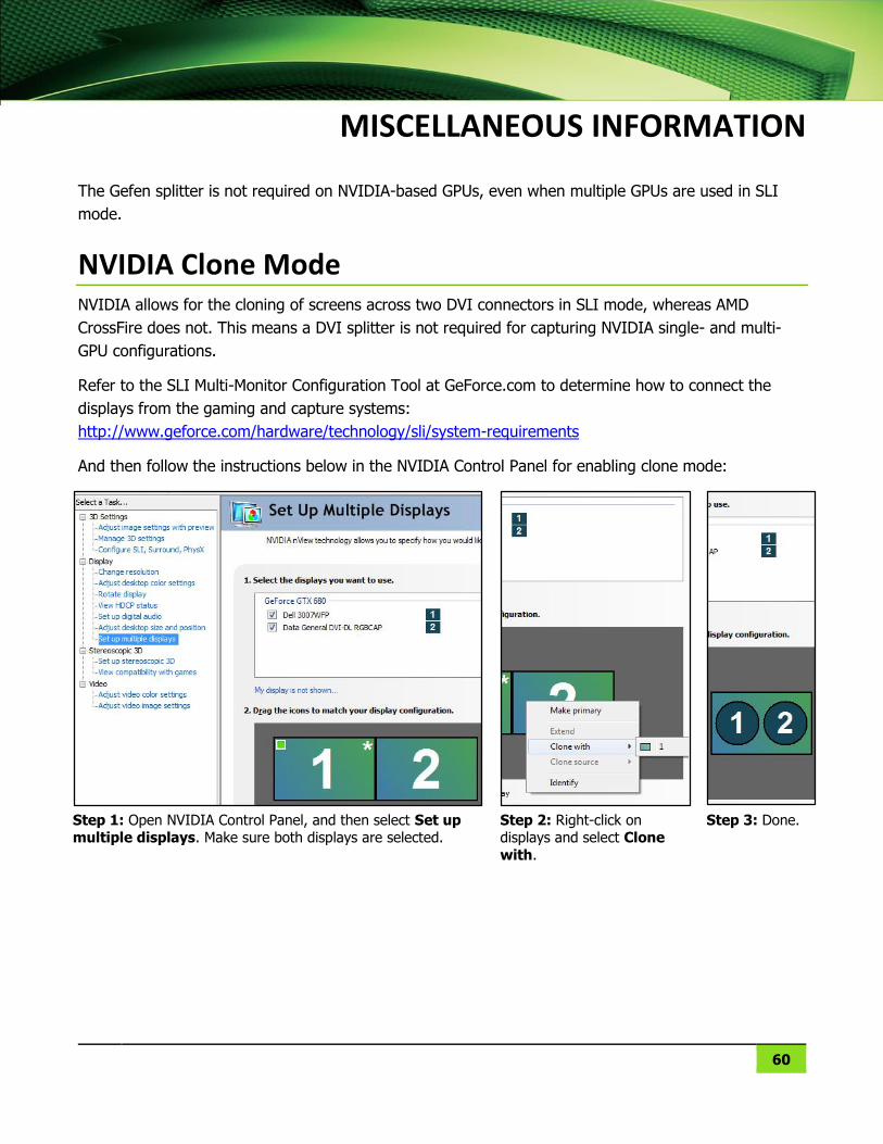
And then follow the instructions below in the NVIDIA Control Panel for enabling clone mode:
Step 1: Open NVIDIA Control Panel, and then select Set up multiple displays. Make sure both displays are selected.
Step 2: Right-click on displays and select Clone
with.
Step 3: Done.
61
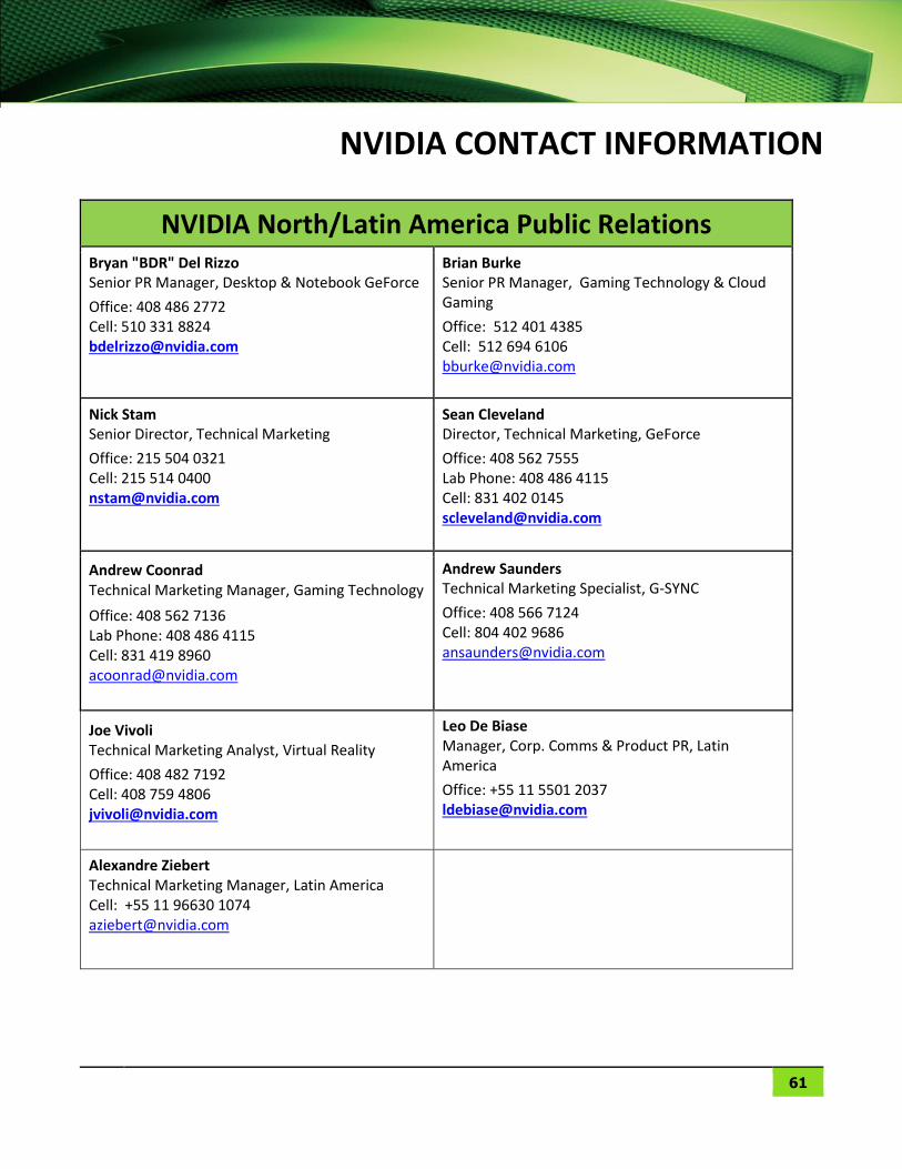
NVIDIA CONTACT INFORMATION
NVIDIA North/Latin America Public Relations Bryan "BDR" Del Rizzo Senior PR Manager, Desktop & Notebook GeForce
Office: 408 486 2772 Cell: 510 331 8824 [email protected]
Brian Burke Senior PR Manager, Gaming Technology & Cloud Gaming
Office: 512 401 4385 Cell: 512 694 6106 [email protected]
Nick Stam Senior Director, Technical Marketing
Office: 215 504 0321 Cell: 215 514 0400 [email protected]
Sean Cleveland Director, Technical Marketing, GeForce
Office: 408 562 7555 Lab Phone: 408 486 4115 Cell: 831 402 0145 [email protected]
Andrew Coonrad Technical Marketing Manager, Gaming Technology
Office: 408 562 7136 Lab Phone: 408 486 4115 Cell: 831 419 8960 [email protected]
Andrew Saunders Technical Marketing Specialist, G-SYNC
Office: 408 566 7124 Cell: 804 402 9686 [email protected]
Joe Vivoli Technical Marketing Analyst, Virtual Reality
Office: 408 482 7192 Cell: 408 759 4806 [email protected]
Leo De Biase Manager, Corp. Comms & Product PR, Latin America
Office: +55 11 5501 2037 [email protected]
Alexandre Ziebert Technical Marketing Manager, Latin America Cell: +55 11 96630 1074 [email protected]
FCAT Reviewer's Guide NVIDIA CONTACT INFORMATION
62
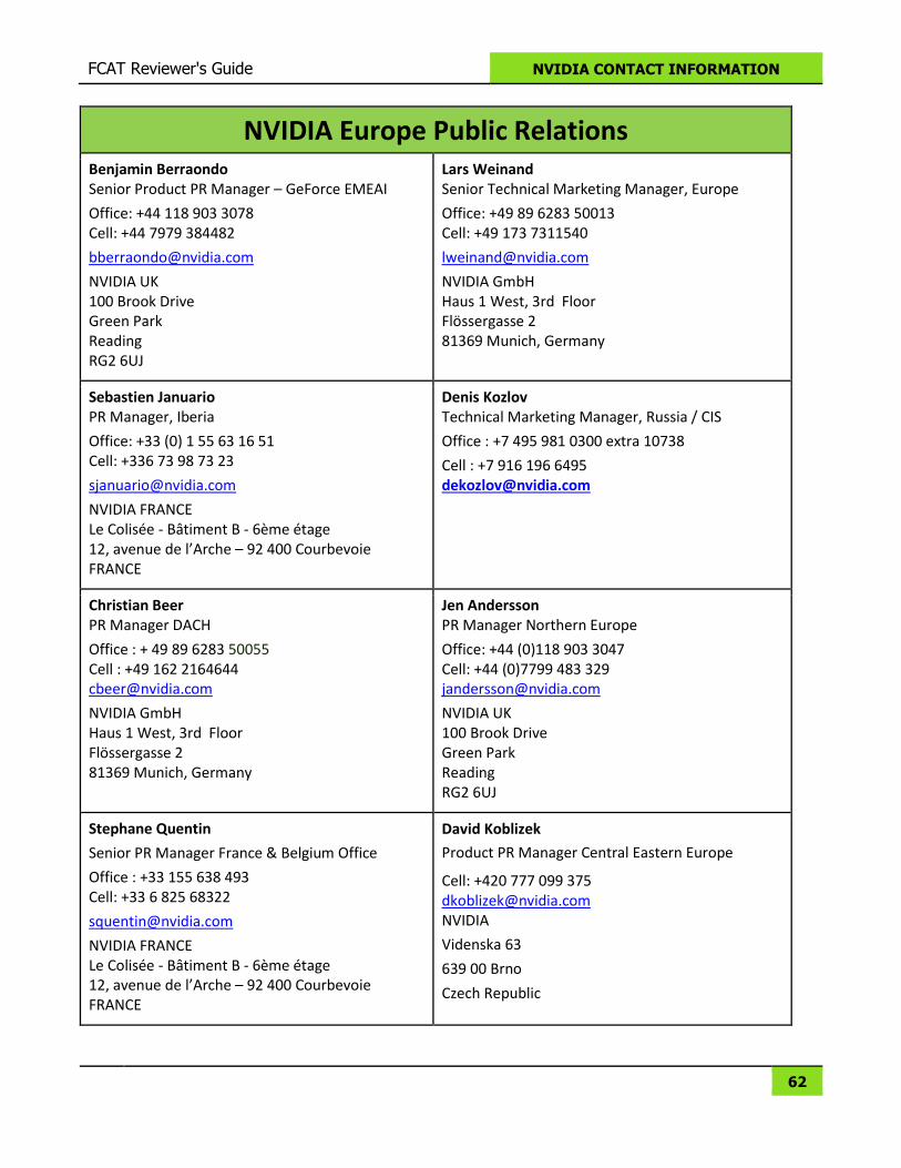
NVIDIA Europe Public Relations Benjamin Berraondo Senior Product PR Manager – GeForce EMEAI
Office: +44 118 903 3078 Cell: +44 7979 384482
NVIDIA UK 100 Brook Drive Green Park Reading RG2 6UJ
Lars Weinand Senior Technical Marketing Manager, Europe
Office: +49 89 6283 50013 Cell: +49 173 7311540
NVIDIA GmbH Haus 1 West, 3rd Floor Flössergasse 2 81369 Munich, Germany
Sebastien Januario PR Manager, Iberia
Office: +33 (0) 1 55 63 16 51 Cell: +336 73 98 73 23
NVIDIA FRANCE Le Colisée - Bâtiment B - 6ème étage 12, avenue de l’Arche – 92 400 Courbevoie FRANCE
Denis Kozlov Technical Marketing Manager, Russia / CIS
Office : +7 495 981 0300 extra 10738
Cell : +7 916 196 6495 [email protected]
Christian Beer PR Manager DACH
Office : + 49 89 6283 50055 Cell : +49 162 2164644 [email protected]
NVIDIA GmbH Haus 1 West, 3rd Floor Flössergasse 2 81369 Munich, Germany
Jen Andersson PR Manager Northern Europe
Office: +44 (0)118 903 3047 Cell: +44 (0)7799 483 329 [email protected]
NVIDIA UK 100 Brook Drive Green Park Reading RG2 6UJ
Stephane Quentin
Senior PR Manager France & Belgium Office
Office : +33 155 638 493 Cell: +33 6 825 68322
NVIDIA FRANCE Le Colisée - Bâtiment B - 6ème étage 12, avenue de l’Arche – 92 400 Courbevoie FRANCE
David Koblizek
Product PR Manager Central Eastern Europe
Cell: +420 777 099 375 [email protected] NVIDIA
Videnska 63
639 00 Brno
Czech Republic
FCAT Reviewer's Guide NVIDIA CONTACT INFORMATION
63
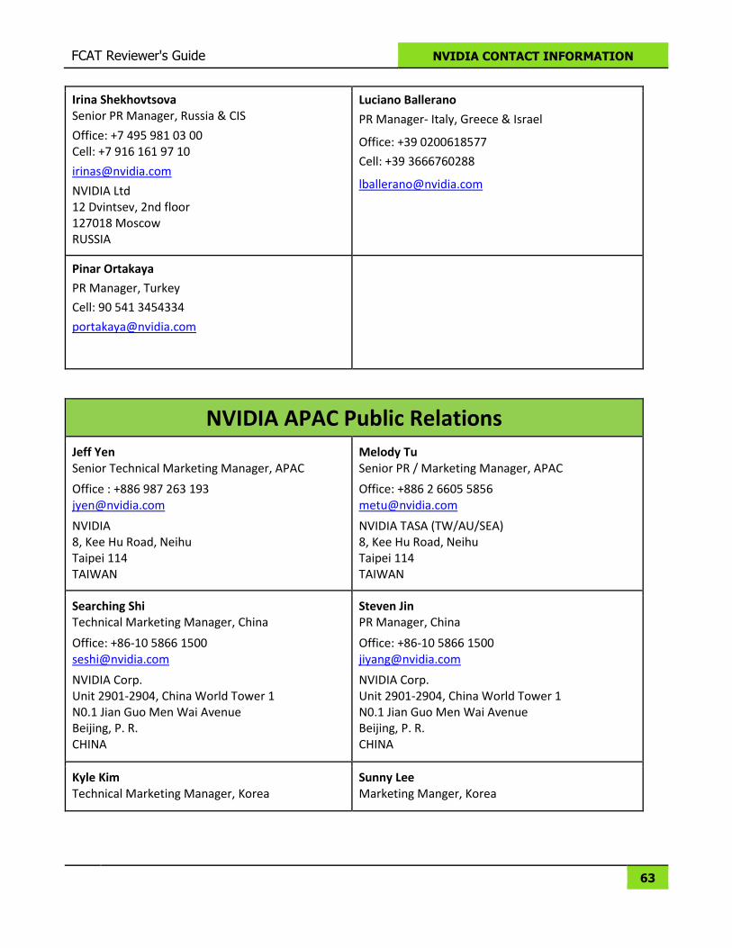
Irina Shekhovtsova Senior PR Manager, Russia & CIS
Office: +7 495 981 03 00 Cell: +7 916 161 97 10
NVIDIA Ltd 12 Dvintsev, 2nd floor 127018 Moscow RUSSIA
Luciano Ballerano
PR Manager- Italy, Greece & Israel
Office: +39 0200618577
Cell: +39 3666760288
Pinar Ortakaya
PR Manager, Turkey
Cell: 90 541 3454334
NVIDIA APAC Public Relations Jeff Yen Senior Technical Marketing Manager, APAC
Office : +886 987 263 193 [email protected]
NVIDIA 8, Kee Hu Road, Neihu Taipei 114 TAIWAN
Melody Tu Senior PR / Marketing Manager, APAC
Office: +886 2 6605 5856 [email protected]
NVIDIA TASA (TW/AU/SEA) 8, Kee Hu Road, Neihu Taipei 114 TAIWAN
Searching Shi Technical Marketing Manager, China
Office: +86-10 5866 1500 [email protected]
NVIDIA Corp. Unit 2901-2904, China World Tower 1 N0.1 Jian Guo Men Wai Avenue Beijing, P. R. CHINA
Steven Jin PR Manager, China
Office: +86-10 5866 1500 [email protected]
NVIDIA Corp. Unit 2901-2904, China World Tower 1 N0.1 Jian Guo Men Wai Avenue Beijing, P. R. CHINA
Kyle Kim Technical Marketing Manager, Korea
Sunny Lee Marketing Manger, Korea
FCAT Reviewer's Guide NVIDIA CONTACT INFORMATION
64
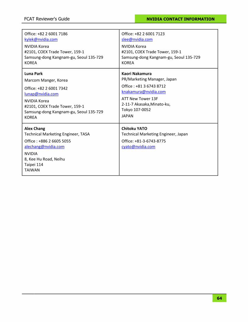
Office: +82 2 6001 7186 [email protected]
NVIDIA Korea #2101, COEX Trade Tower, 159-1 Samsung-dong Kangnam-gu, Seoul 135-729 KOREA
Office: +82 2 6001 7123 [email protected]
NVIDIA Korea #2101, COEX Trade Tower, 159-1 Samsung-dong Kangnam-gu, Seoul 135-729 KOREA
Luna Park
Marcom Manger, Korea
Office: +82 2 6001 7342 [email protected]
NVIDIA Korea #2101, COEX Trade Tower, 159-1 Samsung-dong Kangnam-gu, Seoul 135-729 KOREA
Kaori Nakamura PR/Marketing Manager, Japan
Office : +81 3 6743 8712 [email protected]
ATT New Tower 13F 2-11-7 Akasaka,Minato-ku, Tokyo 107-0052
JAPAN
Alex Chang Technical Marketing Engineer, TASA
Office : +886 2 6605 5055 [email protected]
NVIDIA 8, Kee Hu Road, Neihu Taipei 114 TAIWAN
Chitoku YATO Technical Marketing Engineer, Japan
Office: +81-3-6743-8775 [email protected]
FCAT Reviewer's Guide NVIDIA CONTACT INFORMATION
65
NOTICE
ALL INFORMATION PROVIDED IN THIS WHITE PAPER, INCLUDING COMMENTARY, OPINION, NVIDIA
DESIGN SPECIFICATIONS, REFERENCE BOARDS, FILES, DRAWINGS, DIAGNOSTICS, LISTS, AND
OTHER DOCUMENTS (TOGETHER AND SEPARATELY, “MATERIALS”) ARE BEING PROVIDED “AS IS.”
NVIDIA MAKES NO WARRANTIES, EXPRESSED, IMPLIED, STATUTORY, OR OTHERWISE WITH RESPECT
TO MATERIALS, AND EXPRESSLY DISCLAIMS ALL IMPLIED WARRANTIES OF NONINFRINGEMENT,
MERCHANTABILITY, AND FITNESS FOR A PARTICULAR PURPOSE.
Information furnished is believed to be accurate and reliable. However, NVIDIA Corporation assumes
no responsibility for the consequences of use of such information or for any infringement of patents or
other rights of third parties that may result from its use. No license is granted by implication or
otherwise under any patent or patent rights of NVIDIA Corporation. Specifications mentioned in this
publication are subject to change without notice. This publication supersedes and replaces all
information previously supplied. NVIDIA Corporation products are not authorized for use as critical
components in life support devices or systems without express written approval of NVIDIA Corporation.
Trademarks
NVIDIA, the NVIDIA logo, and GeForce are trademarks or registered trademarks of NVIDIA Corporation
in the United States and other countries. Other company and product names may be trademarks of the
respective companies with which they are associated.
Copyright
© 2015 NVIDIA Corporation. All rights reserved.