Embed Size (px)
Citation preview
Controlled Documentation
DO NOT DUPLICATE. CONFIDENTIAL INFORMATION AND PROTECTED UNDER U.S. COPYRIGHT LAWS © 2019 FACTORY FIVE RACING, INC.
company\instructions\KRC Power steering Coyote ROADSTER-COUPE
1
Part Number:16531 Revision: C Effective Date: 6/28/19 By: J. INGERSLEV & J. DEAN
Coyote KRC Power Steering kit
R O A D S T E R A N D C O U P E
I N S T A L L A T I O N I N S T R U C T I O N S
Table of Contents Tools required ................................................................................. 1
Supplies needed ............................................................................. 1
Using a serpentine belt as a strap wrench ...................................... 2
Parts preparation ............................................................................ 4
Engine ....................................................................................................... 4
Installation ....................................................................................... 7
Power steering pump bracket ................................................................... 7
Water pump pulley .................................................................................. 11
Power steering pump .............................................................................. 14
Serpentine belts ...................................................................................... 16
Power steering rack ................................................................................ 18
Power steering lines ............................................................................... 22
Bleeding the system ...................................................................... 25
Power steering alignment specifications ....................................... 25
Adjusting the upper control Arm ............................................................. 25
Tools required
10mm socket
Ratchet
¼”, 5mm, 6mm Hex Keys
Torque wrench
Supplies needed
Power steering fluid
Blue Loctite
2
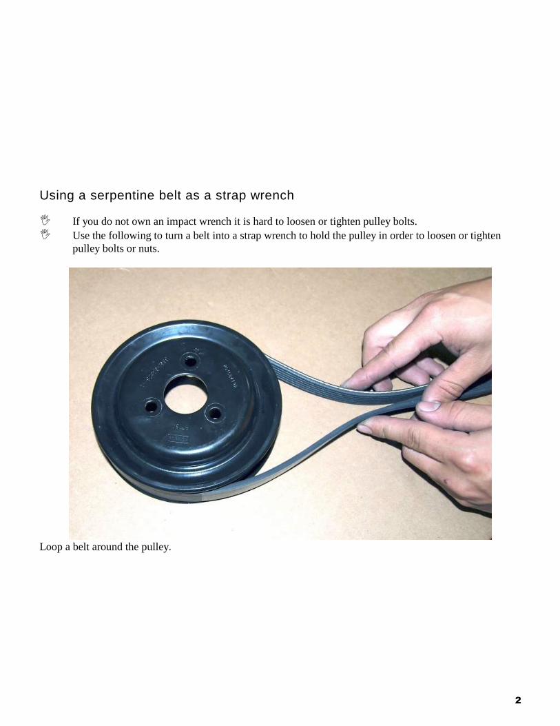
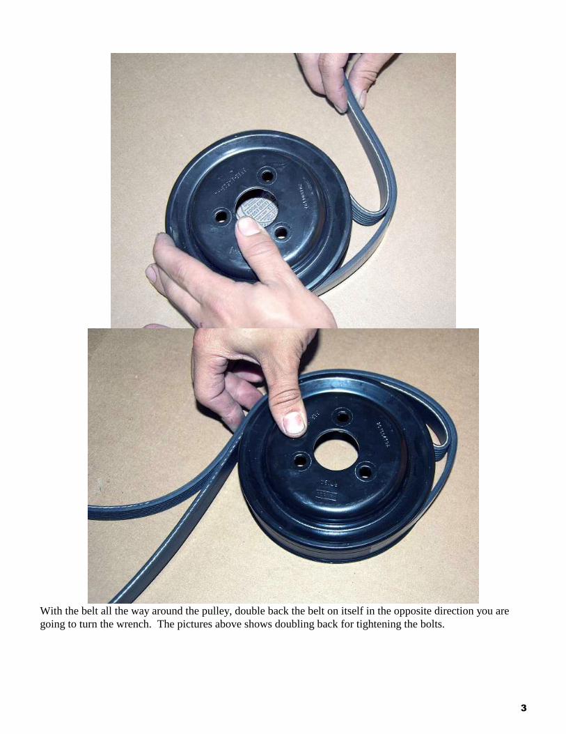
Using a serpentine belt as a strap wrench
If you do not own an impact wrench it is hard to loosen or tighten pulley bolts.
Use the following to turn a belt into a strap wrench to hold the pulley in order to loosen or tighten
pulley bolts or nuts.
Loop a belt around the pulley.
3
With the belt all the way around the pulley, double back the belt on itself in the opposite direction you are
going to turn the wrench. The pictures above shows doubling back for tightening the bolts.
4
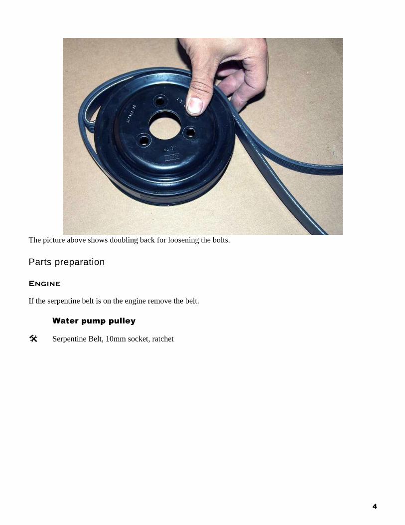
The picture above shows doubling back for loosening the bolts.
Parts preparation
Engine
If the serpentine belt is on the engine remove the belt.
Water pump pulley
Serpentine Belt, 10mm socket, ratchet
5
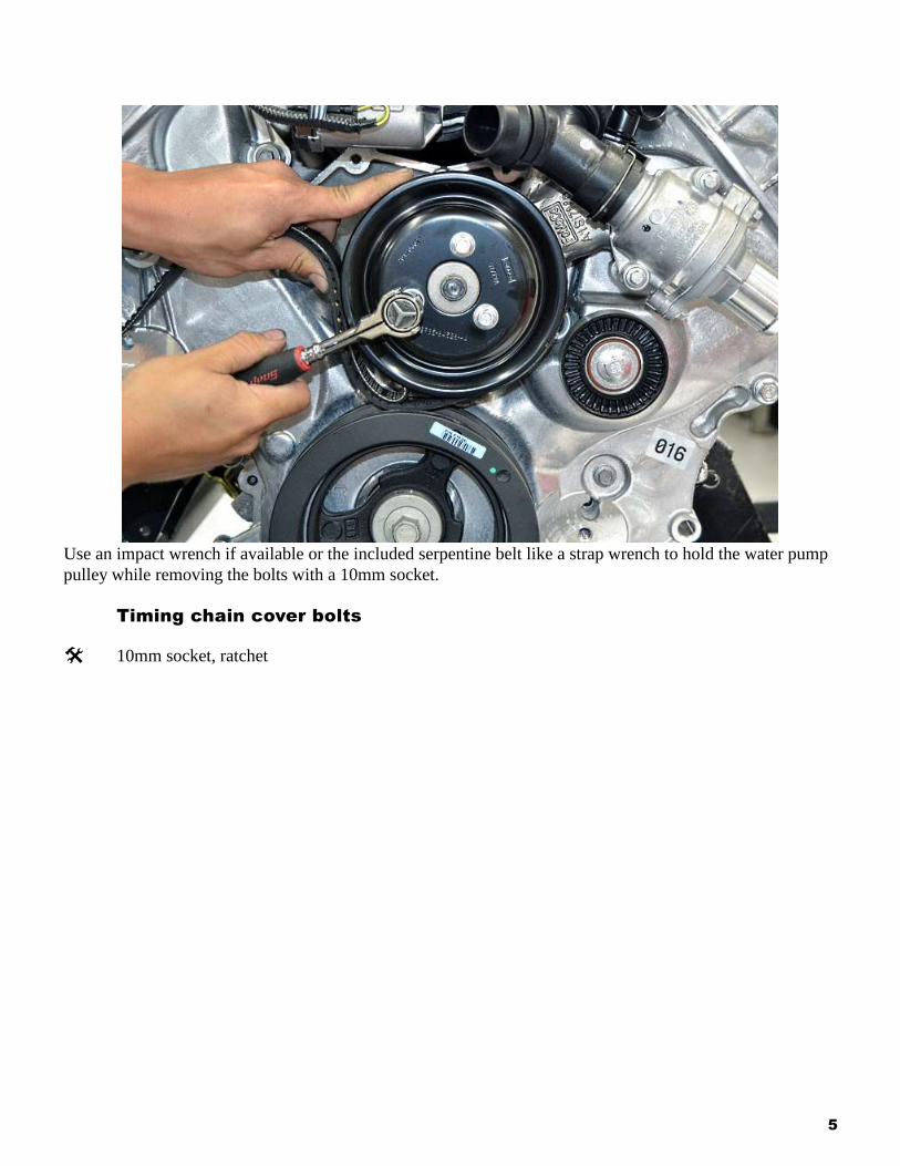
Use an impact wrench if available or the included serpentine belt like a strap wrench to hold the water pump
pulley while removing the bolts with a 10mm socket.
Timing chain cover bolts
10mm socket, ratchet
6
7
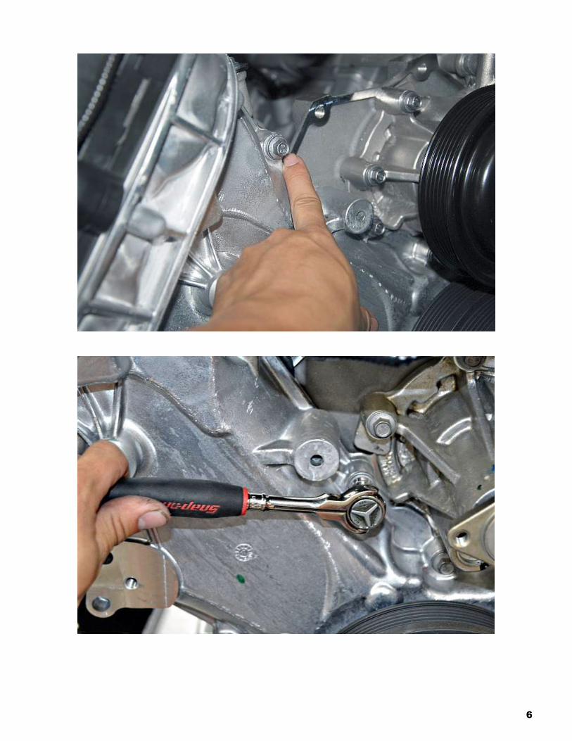
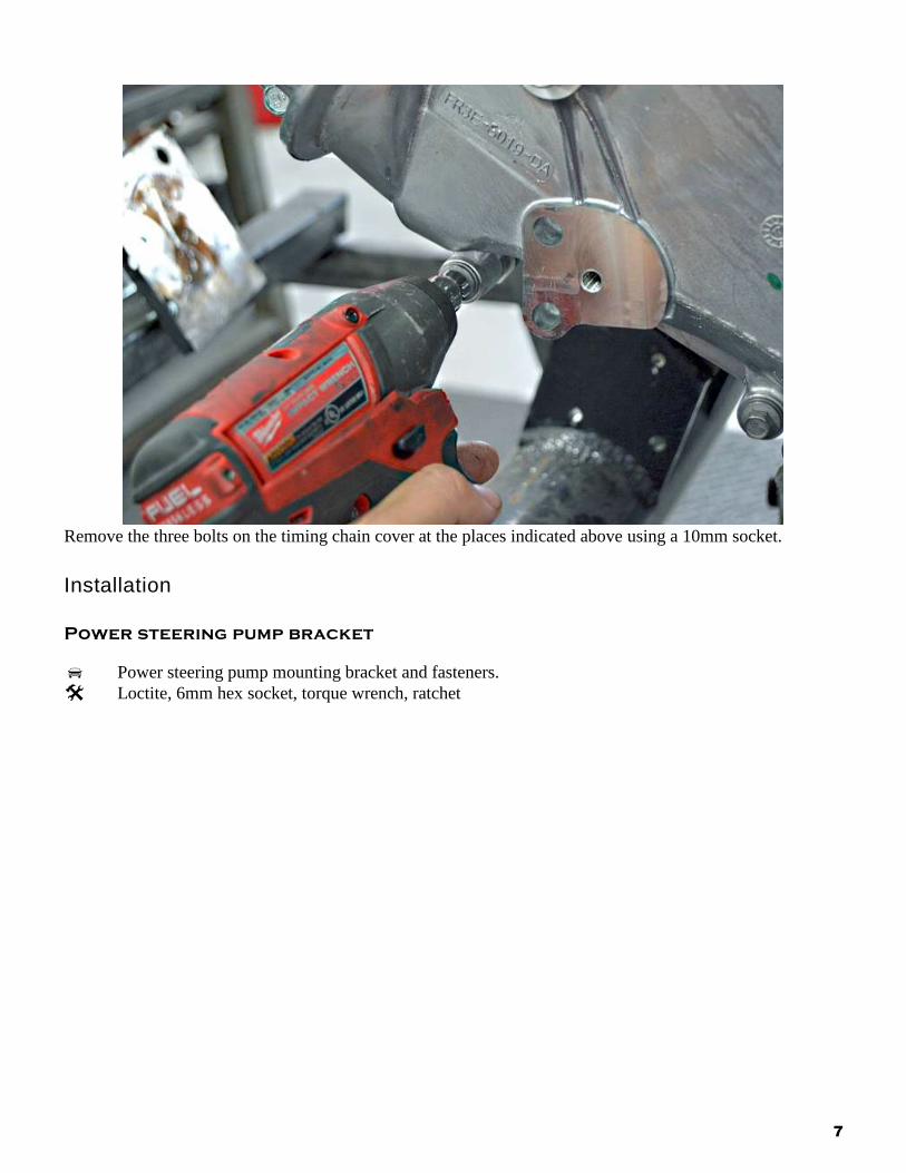
Remove the three bolts on the timing chain cover at the places indicated above using a 10mm socket.
Installation
Power steering pump bracket
Power steering pump mounting bracket and fasteners.
Loctite, 6mm hex socket, torque wrench, ratchet
8
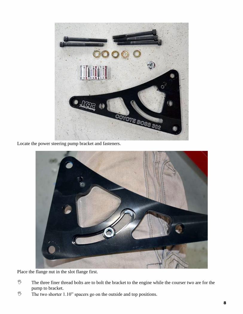
Locate the power steering pump bracket and fasteners.
Place the flange nut in the slot flange first.
The three finer thread bolts are to bolt the bracket to the engine while the courser two are for the
pump to bracket.
The two shorter 1.10” spacers go on the outside and top positions.
9
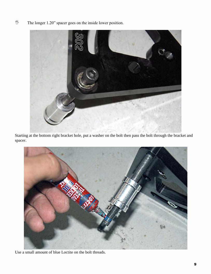
The longer 1.20” spacer goes on the inside lower position.
Starting at the bottom right bracket hole, put a washer on the bolt then pass the bolt through the bracket and
spacer.
Use a small amount of blue Loctite on the bolt threads.
10
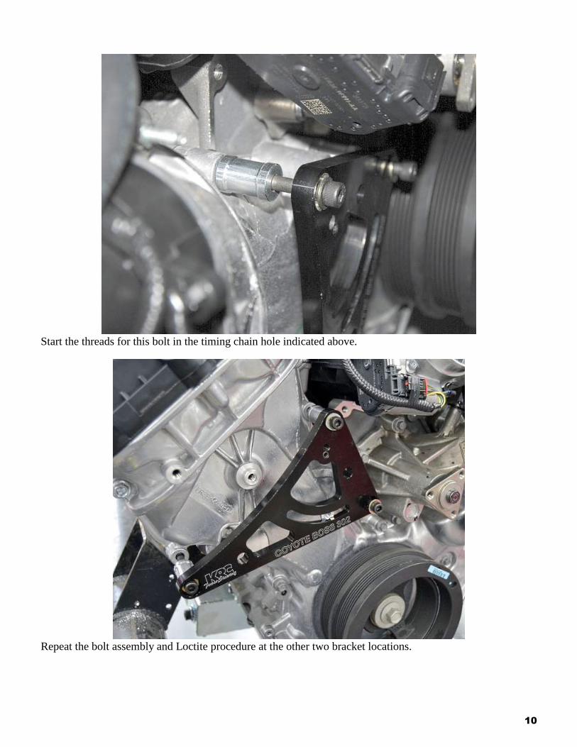
Start the threads for this bolt in the timing chain hole indicated above.
Repeat the bolt assembly and Loctite procedure at the other two bracket locations.
11
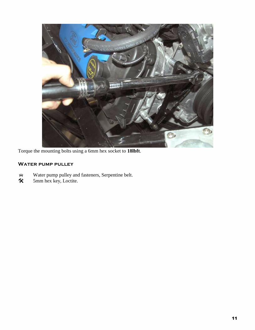
Torque the mounting bolts using a 6mm hex socket to 18lbft.
Water pump pulley
Water pump pulley and fasteners, Serpentine belt.
5mm hex key, Loctite.
12
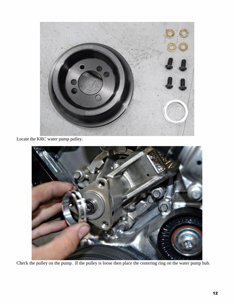
Locate the KRC water pump pulley.
Check the pulley on the pump. If the pulley is loose then place the centering ring on the water pump hub.
13
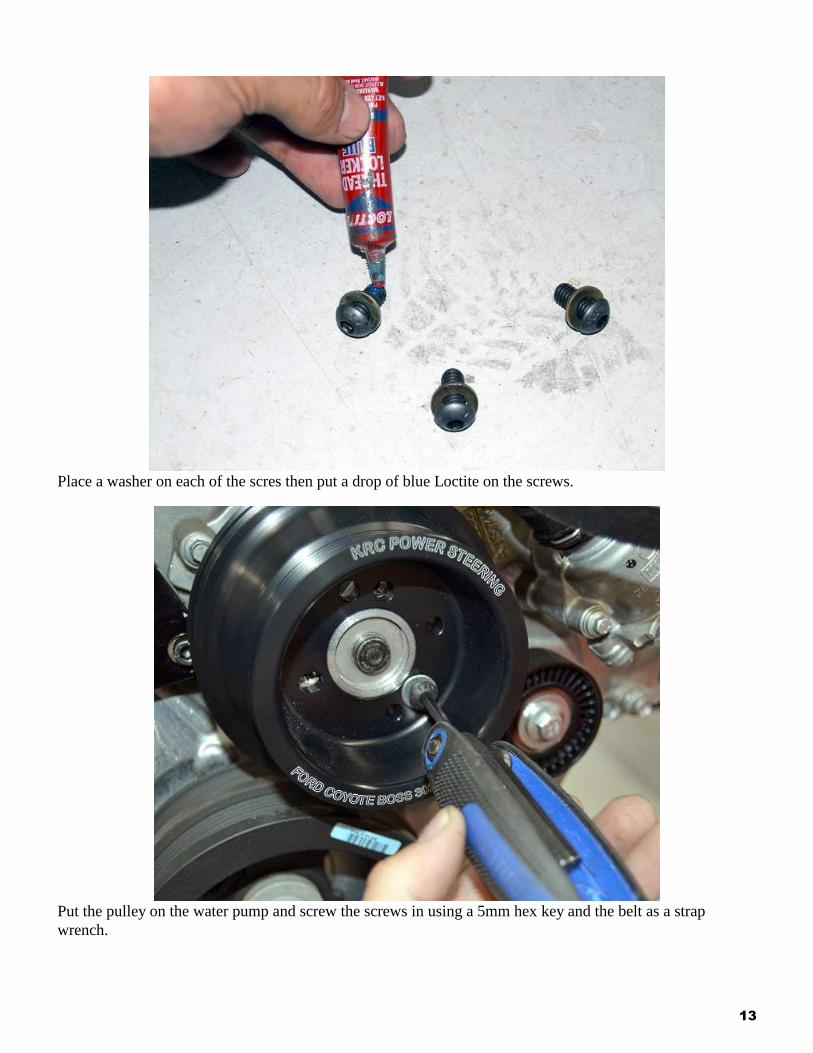
Place a washer on each of the scres then put a drop of blue Loctite on the screws.
Put the pulley on the water pump and screw the screws in using a 5mm hex key and the belt as a strap
wrench.
14
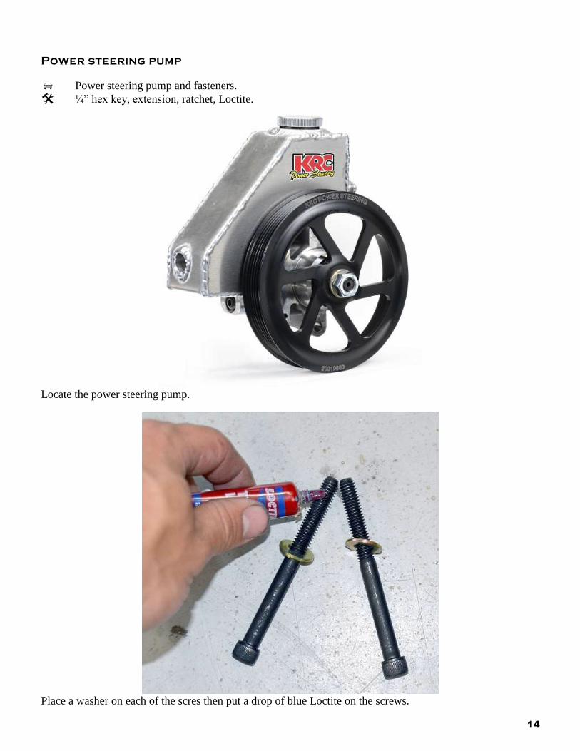
Power steering pump
Power steering pump and fasteners.
¼” hex key, extension, ratchet, Loctite.
Locate the power steering pump.
Place a washer on each of the scres then put a drop of blue Loctite on the screws.
15
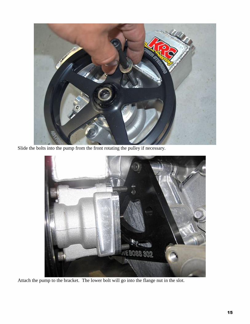
Slide the bolts into the pump from the front rotating the pulley if necessary.
Attach the pump to the bracket. The lower bolt will go into the flange nut in the slot.
16
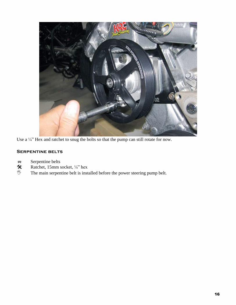
Use a ¼” Hex and ratchet to snug the bolts so that the pump can still rotate for now.
Serpentine belts
Serpentine belts
Ratchet, 15mm socket, ¼” hex
The main serpentine belt is installed before the power steering pump belt.
17
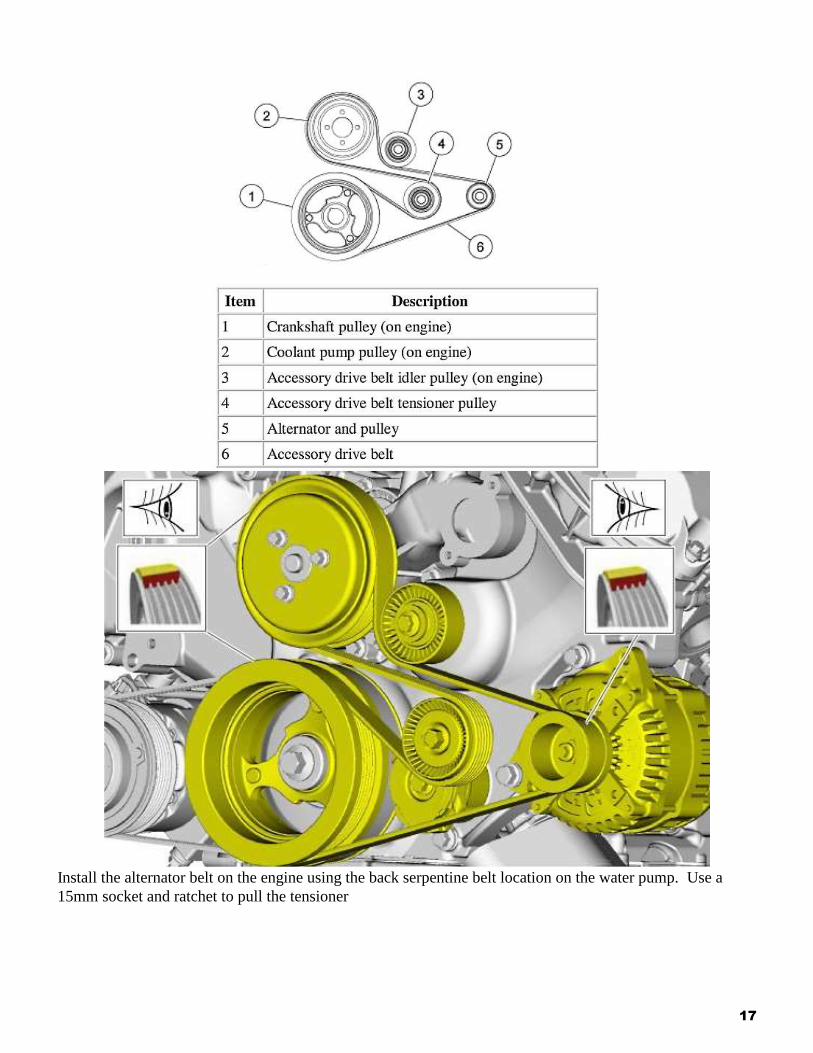
Install the alternator belt on the engine using the back serpentine belt location on the water pump. Use a
15mm socket and ratchet to pull the tensioner
18
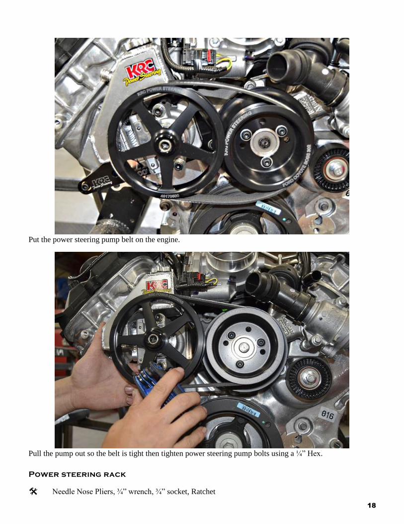
Put the power steering pump belt on the engine.
Pull the pump out so the belt is tight then tighten power steering pump bolts using a ¼” Hex.
Power steering rack
Needle Nose Pliers, ¾” wrench, ¾” socket, Ratchet
19
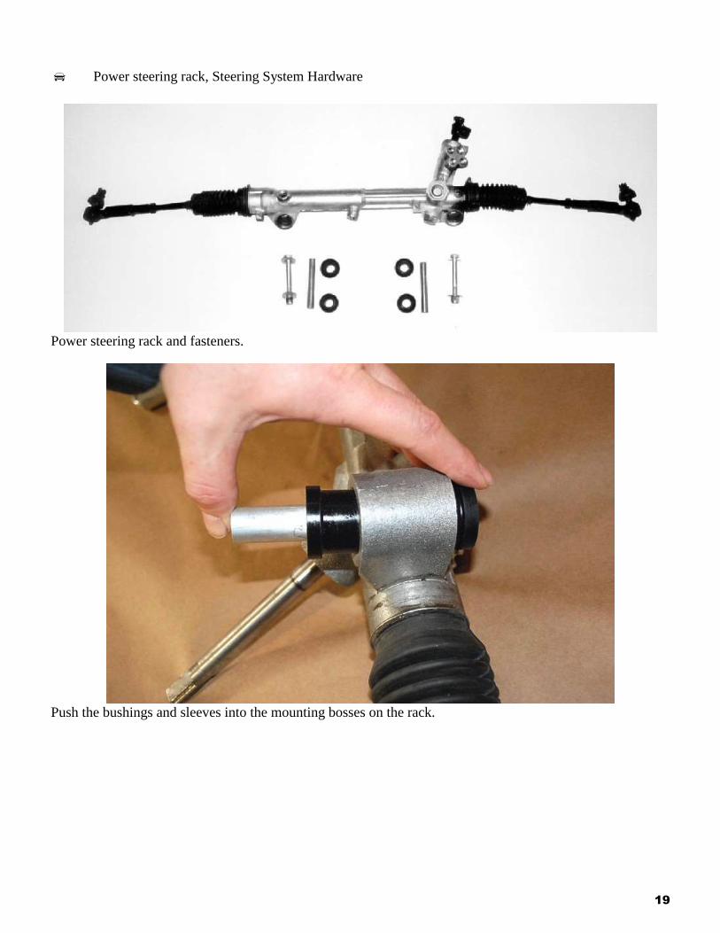
Power steering rack, Steering System Hardware
Power steering rack and fasteners.
Push the bushings and sleeves into the mounting bosses on the rack.
20
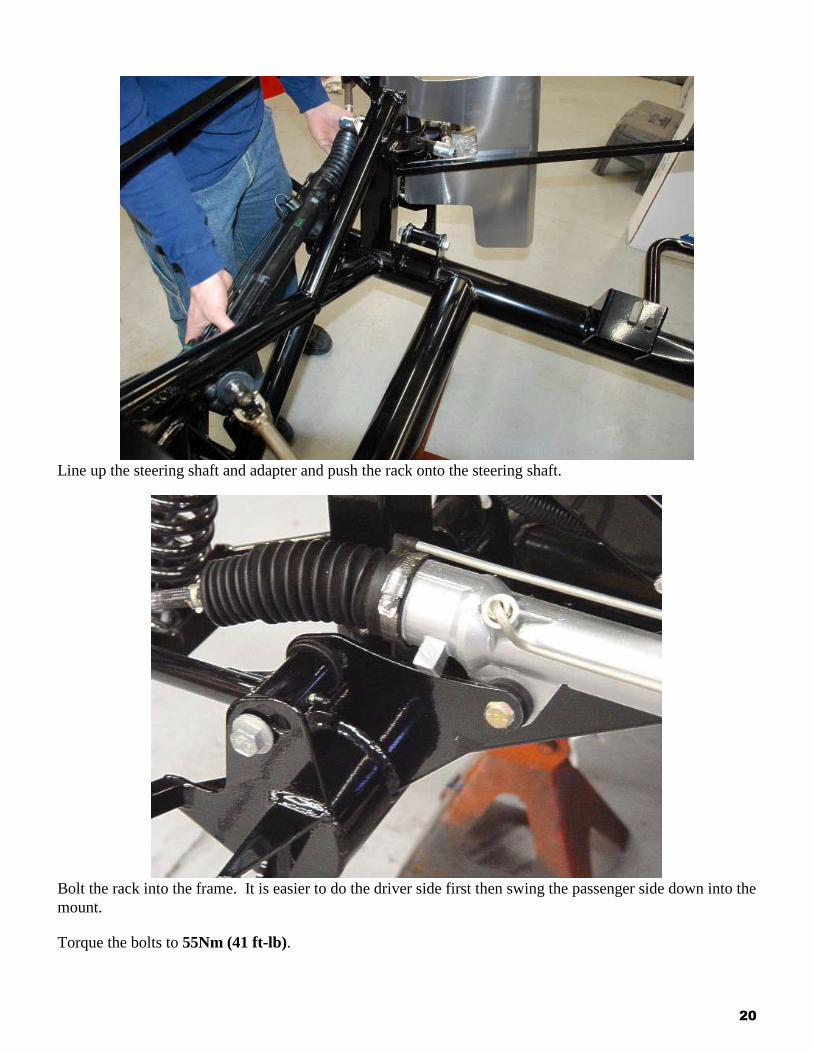
Line up the steering shaft and adapter and push the rack onto the steering shaft.
Bolt the rack into the frame. It is easier to do the driver side first then swing the passenger side down into the
mount.
Torque the bolts to 55Nm (41 ft-lb).
21
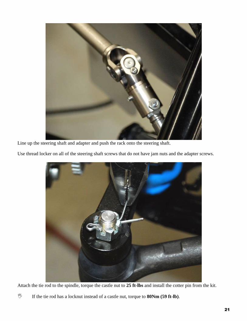
Line up the steering shaft and adapter and push the rack onto the steering shaft.
Use thread locker on all of the steering shaft screws that do not have jam nuts and the adapter screws.
Attach the tie rod to the spindle, torque the castle nut to 25 ft-lbs and install the cotter pin from the kit.
If the tie rod has a locknut instead of a castle nut, torque to 80Nm (59 ft-lb).
22
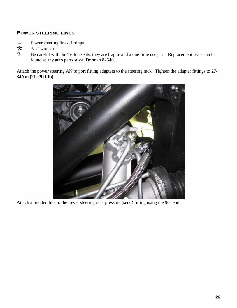
Power steering lines
Power steering lines, fittings.
11/16” wrench
Be careful with the Teflon seals, they are fragile and a one-time use part. Replacement seals can be
found at any auto parts store, Dorman 82540.
Attach the power steering AN to port fitting adapters to the steering rack. Tighten the adapter fittings to 27-
34Nm (21-29 ft-lb).
Attach a braided line to the lower steering rack pressure (send) fitting using the 90° end.
23
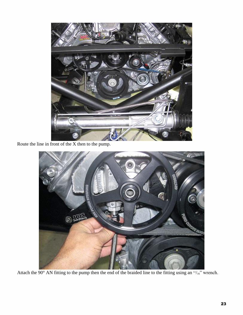
Route the line in front of the X then to the pump.
Attach the 90° AN fitting to the pump then the end of the braided line to the fitting using an 11/16” wrench.
24
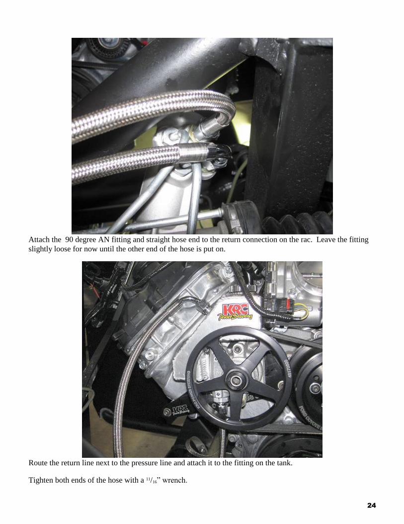
Attach the 90 degree AN fitting and straight hose end to the return connection on the rac. Leave the fitting
slightly loose for now until the other end of the hose is put on.
Route the return line next to the pressure line and attach it to the fitting on the tank.
Tighten both ends of the hose with a 11/16” wrench.
25
Bleeding the system
Power steering fluid.
Jack, jack stands.
Jack the front of the car up so the front wheels are off the ground and place on jack stands.
Fill the power steering fluid reservoir with fluid.
Turn the steering wheel slowly lock to lock.
Check the steering fluid level.
Do not hold the steering wheel at full lock while bleeding the system.
Start the engine and turn the steering wheel lock-to-lock.
Lower the car off the jack stands.
Power steering alignment specifications
Caster: 7
Camber: -0.5
Total Toe: 1/16”
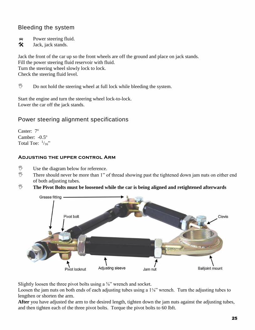
Adjusting the upper control Arm
Use the diagram below for reference.
There should never be more than 1” of thread showing past the tightened down jam nuts on either end
of both adjusting tubes.
The Pivot Bolts must be loosened while the car is being aligned and retightened afterwards
Slightly loosen the three pivot bolts using a ⅝” wrench and socket.
Loosen the jam nuts on both ends of each adjusting tubes using a 1⅛” wrench. Turn the adjusting tubes to
lengthen or shorten the arm.
After you have adjusted the arm to the desired length, tighten down the jam nuts against the adjusting tubes,
and then tighten each of the three pivot bolts. Torque the pivot bolts to 60 lbft.

26
Grease both ends using chassis grease frequently to insure smooth, trouble free operation.