Embed Size (px)
Citation preview

Revista Mexicana de Ingeniería Química
CONTENIDO
Volumen 8, número 3, 2009 / Volume 8, number 3, 2009
213 Derivation and application of the Stefan-Maxwell equations
(Desarrollo y aplicación de las ecuaciones de Stefan-Maxwell)
Stephen Whitaker
Biotecnología / Biotechnology
245 Modelado de la biodegradación en biorreactores de lodos de hidrocarburos totales del petróleo
intemperizados en suelos y sedimentos
(Biodegradation modeling of sludge bioreactors of total petroleum hydrocarbons weathering in soil
and sediments)
S.A. Medina-Moreno, S. Huerta-Ochoa, C.A. Lucho-Constantino, L. Aguilera-Vázquez, A. Jiménez-
González y M. Gutiérrez-Rojas
259 Crecimiento, sobrevivencia y adaptación de Bifidobacterium infantis a condiciones ácidas
(Growth, survival and adaptation of Bifidobacterium infantis to acidic conditions)
L. Mayorga-Reyes, P. Bustamante-Camilo, A. Gutiérrez-Nava, E. Barranco-Florido y A. Azaola-
Espinosa
265 Statistical approach to optimization of ethanol fermentation by Saccharomyces cerevisiae in the
presence of Valfor® zeolite NaA
(Optimización estadística de la fermentación etanólica de Saccharomyces cerevisiae en presencia de
zeolita Valfor® zeolite NaA)
G. Inei-Shizukawa, H. A. Velasco-Bedrán, G. F. Gutiérrez-López and H. Hernández-Sánchez
Ingeniería de procesos / Process engineering
271 Localización de una planta industrial: Revisión crítica y adecuación de los criterios empleados en
esta decisión
(Plant site selection: Critical review and adequation criteria used in this decision)
J.R. Medina, R.L. Romero y G.A. Pérez
Revista Mexicanade Ingenierıa Quımica
1
Academia Mexicana de Investigacion y Docencia en Ingenierıa Quımica, A.C.
Volumen 9, Numero 3, Diciembre 2010
ISSN 1665-2738
1Vol. 9, No. 3 (2010) 367-382
MODELING THE CONFIGURATION CHARACTERISTICS ANDOPERATING REGIMES OF A BINARY DISTILLATION COLUMN FOR
CONTROL
MODELADO DE LAS CARACTERISTICAS DE CONFIGURACION YREGIMENES DE OPERACION DE UNA COLUMNA DE DESTILACION
BINARIA PARA SU CONTROL
D. Juarez-Romero1∗, F.R. Lopez-Estrada3, C.M. Astorga-Zaragoza2, V. Alvarado2, J.A. Hernandez1 andA.C. Tellez-Anguiano2
1Centro de Investigacion en Ingenierıa y Ciencias Aplicadas, Universidad Autonoma del Estado deMorelos, Av. Universidad 1001, Col Chamilpa, Cuernavaca, Morelos, Mexico, C.P. 62209
2Centro Nacional de Investigacion y Desarrollo Tecnologico, Interior Internado Palmira s/n, Col.Palmira. Cuernavaca, Morelos, Cuernavaca, Morelos, Mexico. C.P. 62490
3Instituto Tecnologico de Tuxtla Gutierrez, Departamento de Ingenierıa Electrica y Electronica Carreterapanamericana Km 1080 S/N, CP 29000, Tuxtla, Gutierrez, Chiapas, Mexico
Recieved 29 of November 2009; Accepted 12 of October 2010
AbstractThis work describes a mathematical model for a distillation column which includes mass, composition, and energy
balances, where the thermodynamic and equilibrium properties are represented by an equation of state. This model
focuses on the specific configuration of the boiler (container plus boiling vessel) and the vertical condenser (with
an external cooling jacket plus a helical pipe) and also on the effect of atmospheric and subcooling conditions in
the condenser. For the sake of flexibility and to represent consistently the semi-continuous conditions during the
startup, the equations are solved as a DAEs set. Results are compared with experimental data from a Methanol-
Ethanol mixture in a 10-tray distillation column. The effects of configuration and operating conditions on the
model fidelity are discussed. The model describes the semi-continuous hydraulics and the desired temperature
profile that is expected to be used for process control.
Keywords: distillation column dynamics, condensate subcooling, model fidelity, distillation columnconfiguration.
ResumenEste trabajo describe un modelo matematico para una columna de destilacion que incluye los balances de masa,
composicion, y energıa, donde las propiedades termodinamicas y de equilibrio estan representadas por una ecuacion
de estado. Este modelo se enfoca a la descripcion especıfica del rehervidor (que tiene un contenedor mas un tanque
de ebullicion) y el condensador vertical (con una chaqueta de enfriamiento externa, mas un tubo helicoidal) y
tambien los efectos de las condiciones atmosfericas y de sub-enfriamiento en el condensador. A fin de tener
flexibilidad y para representar consistentemente las condiciones semi-continuas durante el arranque, las ecuaciones
son resueltas como un conjunto de EAD. Los resultados son comparados con datos experimentales para una mezcla
metanol-etanol en una destilacion de 10-platos. Se discuten los efectos de la configuracion y las condiciones de
operacion en la fidelidad del modelo. El modelo describe la hidraulica semi-continua y el perfil de temperaturas
que se espera sea utilizado para control de procesos.
Palabras clave: dinamica de columnas de destilacion, subenfriamiento de condensado, fidelidad de modelo,configuracion de columna de destilacion.
∗Corresponding author. E-mail: [email protected]
Publicado por la Academia Mexicana de Investigacion y Docencia en Ingenierıa Quımica A.C. 367

D. Juarez-Romero et al./ Revista Mexicana de Ingenierıa Quımica Vol. 9, No. 3 (2010) 367-382
1 Introduction
The starting aim of this work was the energyintegration of a distillation column by a heatpump. For this aim the Aspen Plus was used(Martınez-Soria, 2001). During this work, itwas observed that the interactions between thestreams of equipment which are part of thethermodynamic cycle harden the convergence.Also Aspen models, as they are devised forgeneral purpose, offer limited description of theconfiguration of equipment. Then, to obtain anadequate diagnosis of the performance, a home-grown distillation model was developed. Thus,the present work presents a detailed model for thedistillation pilot plant located at the Mechatronicslaboratory of CENIDET. The present workemphasizes the development of a model whichconsiders the equipment configuration and thespecific operating conditions. It has beenobserved that the configuration of this column issimilar to other distillation columns available inseveral academic institutions (like the ChemicalDepartment of Celaya Institute of Technology,Chemistry Faculty at UNAM, School of ChemicalEngineering and Extraction Industries at IPN andFaculty of Chemical Sciences and Engineering atUAEM); thus, the improvement of this model willprovide a better understanding of the behaviorof similar columns. For this process, the basicmass and energy balances are known, thus mostof the unknown parameters are related to thehydrodynamic equations and to the heat transferparameters. In this work some of these parametersare evaluated by complementary techniques:experiments in the time domain. The usedstrategy consists in isolating as much as possiblethe effect of each parameter. The objective ofimproving the model fidelity is to enhance thecontrol performance under disturbances.
1.1 Background
To synthesize a multivariable control for agiven process objective, it is necessary to selectmeasured and manipulated variables (inputs,u and outputs, y), which satisfy the basiccriteria of control (observability, controllability,sensitivity). To predict the time variation of statevariables and outputs, instead of using typicalsurface responses, model-based control uses areference model. Predicted outputs are used to
evaluate an objective function (which evaluatesthe difference between experimental outputs andtheir prescribed set trajectory) subject to processconstraints. Finally, an optimizer minimizes forthe increment of inputs, ∆u, the summationduring several sampling times of the squares ofthe objective function with weights Wy, W∆u
(Rossiter, 2003).
minWy∆u
[r(t)− y(u)]T [r(t)− y(u)] +W∆u∆uT∆u
(1)Some of the obstacles to be dealt with inmodel-based control are a) tuning controlvariables (sampling time, predicting and controlhorizon) b) the representation of the effectof unmeasured disturbances and c) reducingmodel/plant mismatch. This work emphasizesthe last issue. Yip and Marlin (2004) in theirwork comparing models with different fidelityhave shown that the performance of Real TimeOptimization to track the changing optimum relieson an accurate model to represent plant behavior.
Since the development of the simplifieddynamic model of a distillation column wasproposed by Wood and Berry (1973), severalimprovements have been made, for instance,models with composition and mass (Cingaraand Jovanovic, 1990) and with energy andcomposition (Gani, et al., 1986) have beendeveloped. In a sequel of these works, Ruiz, etal. (1988), and Eden et al. (2002) found thatthe startup is composed by three stages: 1) ashort discontinuous stage, where the pumps andthe flow start while the heating is in progress;2) a semi-continuous stage, where the hydraulicvariables reach their steady state and the refluxchanges from total to the desired reflux rate; 3) afinal stage, where the column reaches the desiredconditions.
Kister (2002) mentions that two of the majortrouble spots for the development of a distillationmodel are the hydraulic prediction and reliableVLE data. Archambault et al. (1973) analyzedthe operating conditions of the condenser. Theyshowed that for a high ratio of cooling water flowto condensate flow, the condenser operates undersubcooling conditions. Wittgens and Skogestad(2000) in their study on tray hydraulics concludedthat models based on constant molar flowsand linear tray hydraulics gave large deviations.Alpbaz (2002) studied the behavior of the specificconfiguration of a distillation boiler. In a
368 www.amidiq.com

D. Juarez-Romero et al./ Revista Mexicana de Ingenierıa Quımica Vol. 9, No. 3 (2010) 367-382
distillation column with similar characteristics,Gunter (2003) developed several tests to set someparameters of his dynamic model; but this modelwas used during warm start-up. Agachi et al.(2007), after comparing 5 models varying inmodeling difficulty and computational complexity(from DAE models to Artificial Neural Networks)for an ethanol-water distillation column, concludethat fundamental models are attractive becausethey are globally valid and fewer parametersare required for their development. They alsonotice that when a model with high complexityis used, real-time feasibility for control requiresan appropriate optimization strategy.
Furthermore, a project supported by OIT(DOE of USA; 2001) has been launched to developfundamentals-based models for the distillationcolumn operation and to establish the columninternals. From the results of this project, largeenergy savings are expected by year 2020.
1.2 Objective
The objective of this work is to improve ageneral model for a distillation column in orderto increase its fidelity from semi-continuousoperation conditions to the required conditionsat the specified purity. The goal is totranslate accurately the input variables: heatto the reboiler, cooling water flow and itscooling temperature to obtain a product witha desired flow-rate and composition. Anaccurate measurement of the inputs plus a betterphenomenological description produces betteroutput descriptions. As it is evident in the massand energy balances presented in Section 4.1,once the steady state is represented, the dynamicbehavior depends on the initial conditions, theoperating conditions, the physical properties ofthe fluid, and the available geometry of theequipment where the fluid travels (mass-highrelationship in reboiler and condenser; weir, heightand column diameter in trays). Lee (1998) hasmentioned the requirements of an adequate modelfor control: In nonlinear model predictive controla model should enable to predict accurately theeffects of both, known and unknown changes onthe system (output) behavior possibly in a closed-loop setting.
3
Figure 1 Reference distillation column layout
Fig. 1: Reference distillation column layout
2 Process description
The reference distillation column layout ispresented in Fig. 1. The column was made inPyrex crystal. The boiler section is composed bytwo vessels. The smaller vessel is used to heata small part of the overall mixture volume bya heating coil, thus a fast response is obtained;the large vessel is used as a storage tank tocompensate the evaporated fluid. The column isnot insulated, i.e. the glass walls are exposed tothe room temperature. The trays are perforatedwith the down comers located in the center of thetray, with a wide conic section (to reduce pressuredrop and to avoid flooding) which ends in a “J”shape; then, the holdup is used as a liquid seal.To provide a complete and steady condensationthe condenser has two cooling sections. Theinner section is located in the distillation chamber,where a helical pipe condenses the distillate; theouter section is an external cooling jacket. Thisconfiguration ensures total condensation of thedistillate.
The dimensions of the column are presented inTable 1.
2.1 Related instrumentation
Reboiler. The required heat is providedby an electric heating thermo-coil, while itsinstrumentation is formed by one Pt 100 RTDsensor and one electronic temperature indicator.Trays. The main body of the column has 6temperature RTD Pt100 sensors and 6 electronictemperature indicators located at tray 2, 4, 5,7, 9, 10 (consider boiler as number 1). Along the
www.amidiq.com 369
D. Juarez-Romero et al./ Revista Mexicana de Ingenierıa Quımica Vol. 9, No. 3 (2010) 367-382
Table 1. Geometric properties
Property Value
Number of trays 10 (perforated)Tray diameter 10 cmFeed tray 6 from bottomCondenser heat transfer area 0.5 m2
Diameter of down comers 0.5 cmPitch from down comers 0.2 cmWeir height 0.61 cmTray spacing 0.11 mTray diameter 0.10 mReboiler capacity 6 lt with a
boiling vesselof 1 lt
Condenser capacity 1 ltCondenser heat transfer area 0.5 m2
column body, a differential pressure transmitter isused to monitor the difference of pressure betweenthe top and the bottom of the column, a levelindicator is used for the reboiler, and two flowmeters measure the feeding flow and the coolingwater flow of the condenser, respectively.
Feeding subprocess. The feeding mixture isstored in a deposit. Its temperature is controlledby a pre-heating electric thermo-coil. Thisdeposit has one Pt 100 RTD temperature sensor,one electronic temperature indicator, and onetemperature controller. The flow of the feedingmixture is regulated by the pulses of a feedingpump.
Condenser. The condenser has a differentialpressure sensor. The cooling water has two Pt 100RTD temperature sensors and two temperatureindicators. An additional output condensatetemperature was placed. The condenser has alsoone flow transmitter, one flow indicator, one flowcontroller and a 3-way reflux valve. An actuatorregulates the reflux fraction by opening/closingpulses which are controlled by two timers. Thecondenser level is regulated by its geometricdischarge outlet (see Appendix A).
Product. The distilled product is collected in adeposit which has a level transmitter.
Additional measurements were used to definemore clearly the mass and energy balances inthe condenser: the reflux temperature and theenvironmental temperature.
3 Methodology
The development stages start from the availableexperimental LVE data, and configuration ofequipment, with high reliability, through theinteraction between mass-energy, up to theconditions where there is high interaction betweenthermodynamic and hydraulic effects; thus,reliability of data is poor. So, specific experimentswere designed. The following methodology wasused to develop the distillation column model(modified from Dutta and Gualy, 2000):
1. Determine the parameters of a givenequation of state to predict the physicalproperties of the liquid mixture.
2. Determine the configuration of theequipment in the distillation column.
3. Determine the geometry of the differentsections of the distillation column.
4. Select a general model of a distillationcolumn and modify it as required.
5. Define a set of experiments to obtain specificcharacteristics of the heat and mass transferfor the distillation column.
6. Execute specific experiments to fit thetransfer-based parameters.
Static parameters were evaluated before thetest, while dynamic parameters can be adjustedduring the dynamic runs.
These steps are described in the followingparagraphs
• The Stryjek-Vera-Peng-Robinson equationof state was used to represent theequilibrium and thermodynamic propertiesof the Methanol-Ethanol mixture in bothphases. This mixture presents a slightlynon ideal behavior due to hydrogenbonds interaction (Prausnitz et al., 1967).Experimental data reported by Stephan& Hildwein (1987) were used to fit theinteraction parameters (see Appendix B).
• The distillation model developed by Ganiet al. (1986), which appears in AppendixA, was selected. After the comparison ofexperimental and simulated responses theconfiguration of the equipment was detected
370 www.amidiq.com

D. Juarez-Romero et al./ Revista Mexicana de Ingenierıa Quımica Vol. 9, No. 3 (2010) 367-382
as one of the reasons of discrepancy. Modelenhancements are described in Section 4.
• Steady state experiments were executed tovalidate global balances.
• Specific experiments were defined andexecuted. The following operatingconditions were selected to evaluate somemodel parameters:
a) Without feeding. Under this conditionthe column operates as a batch column.
b) Without condensation. This experi-ment is useful to estimate the heatlosses to the environment.
4 Model enhancements
The different sections of the distillation columnare: boiler, trays and condenser. The specificgeometric characteristics are described in thefollowing subsections.
4.1 Reboiler
Fig. 2 shows the geometric characteristics of theboiler. It is a thermosyphon composed by twovessels: a storage vessel and a small vessel wherethe heat is supplied.
The following model was developed to takeinto account the reboiler dynamics of thisconfiguration.Mass balance:
dMb
dt= LBb − VB (2)
Energy balance between vessels:
MbdEbdt
+MBdEBdt
= L2 (El,2 − El,b) (3)
+ LBb (El,B − El,b)− VB (Ev,2 − El,b) +QB
The flow that communicates the storagevessel with the boiling vessel is obtained by thedifferential form of the communicating vessels(dhBdt = dhb
dt
), with consistent initial conditions
(hB = hb at t = 0):
LBb =Ab( ρB
ρ2
L2 − LB) +ABρB
ρbVb
Ab +AB(4)
3
Figure 2. Reboiler with a storage tank
Fig. 2: Reboiler with a storage tank
If only a single vessel were taken into account,the boiling conditions would present at slowerdynamics. Alpbaz et al. (2002) consider onlythe composition dynamics in the vessels, but theenergy dynamics is also important. During thestartup, there are high temperature differencesin the storage and heating vessels which couldproduce diffusion effects in a direction oppositeto the liquid flow.
4.2 Trays
Hydraulics
During the startup, when the vapor pressure issmaller than the environmental pressure, weepingoccurs along the walls at some stages. A difficultyin representing a startup is that when the liquidarrives to its bubble point some vapor is released;thus, the liquid enthalpy decreases, and the vaporpressure presents sudden fluctuations.
This type of fluctuations occurs when theboiling heat is reduced suddenly, and the fluidstops boiling. Under these conditions Patm > P ∗,also there could be some reverse flow.
At every tray, the bottom pressure, Pf isevaluated as Pf = P ∗ + max{0,∆P ∗} + ∆Ph,where ∆P ∗ = (Patm − P ∗), and ∆Ph = gM/A.See Fig 3.
To preserve the consistency in the evaluationof the derivatives used to solve the continuationequations, the expression max{0,∆P ∗} was
approximated as ≈ 0.5√
(∆P ∗)2
+ εp2+0.5∆P ∗.
The derivative of this equation is continuous withrespect to P ∗ (Biegler et al., 1997). Wanget al. (2003) use a discontinuous approach,but the actual process is semi-continuous. Theproposed approach diminishes the restarting of theintegration method.
www.amidiq.com 371
D. Juarez-Romero et al./ Revista Mexicana de Ingenierıa Quımica Vol. 9, No. 3 (2010) 367-382
3
Figure 3. pth tray Fig. 3: pth tray
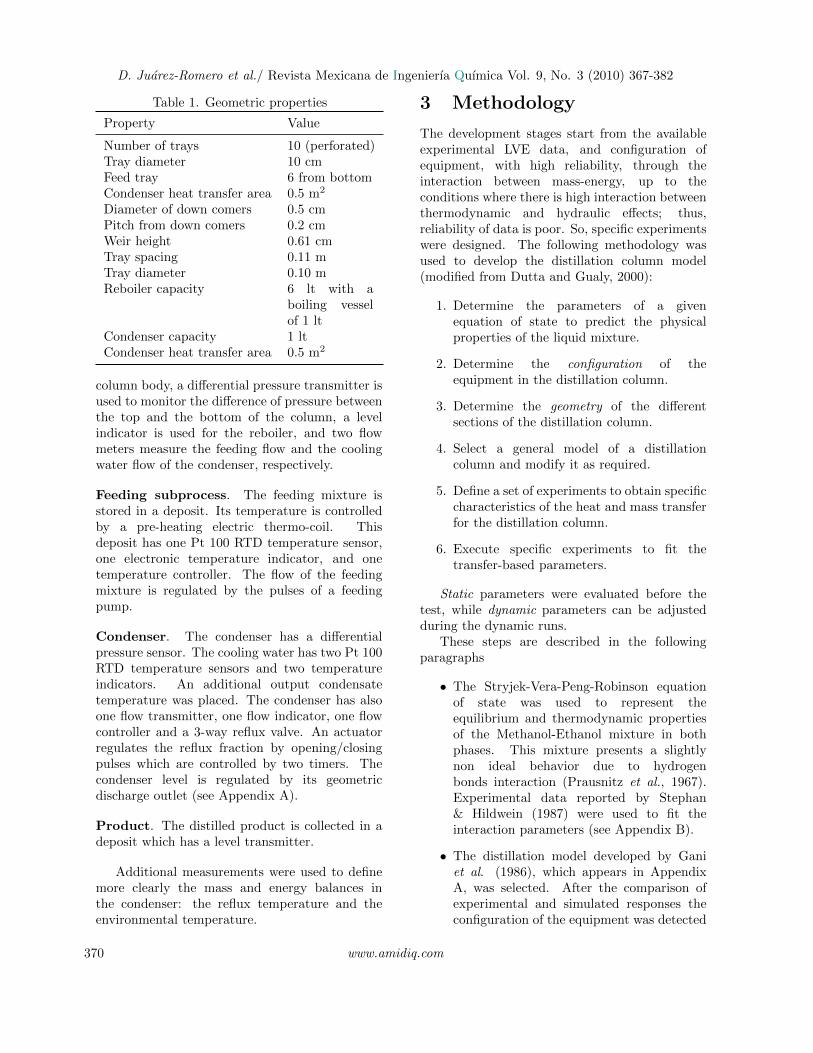
At every tray, the vapor flow and its enthalpydepends upon the differential pressure through thetray.
∆Pv = Pf − P ∗ (5)
Then{∆Pv > 0, V = +
√ρ v∆Pv /kvv, Ev = E∗v
∆Pv < 0, V = −√ρ l|∆Pv|/kvl, Ev = E∗l
(6)Heat losses along the columnSince the condenser operates at atmosphericconditions, and the boiler heat transfer area issmall, the main heat losses occur along the columnbody. If the distillation column is heated until thecondition that no-flow arrives to the condenser,then the heat supplied corresponds to the heatlosses. A similar experiment was carried out byGunter (2003).Selective Condition
LF = 0; B = 0; D = 0 (7)
From the cold start-up, the boiler heat wasincreased until the heat reached the tray beforethe condenser. At that condition, all the heatwas spread in the environment; thus, an overallbalance for all the trays produces
LCEL,Cond + VBEV,B = VCEV,Cond
+ LB+1EL,B +QB +QAtm (8)
In this expression QB is known; while theunknown QAtm, represents the heat losses to theenvironment. Then, when the Newton coolingequation is applied to the column body:
dQAtmdt
=
Np−1∑2
Kp,A(Tp − TAtm) (9)
Heat losses can be estimated at differentoperating conditions by evaluating Kp,A. Thisconstant is humidity dependent.
3
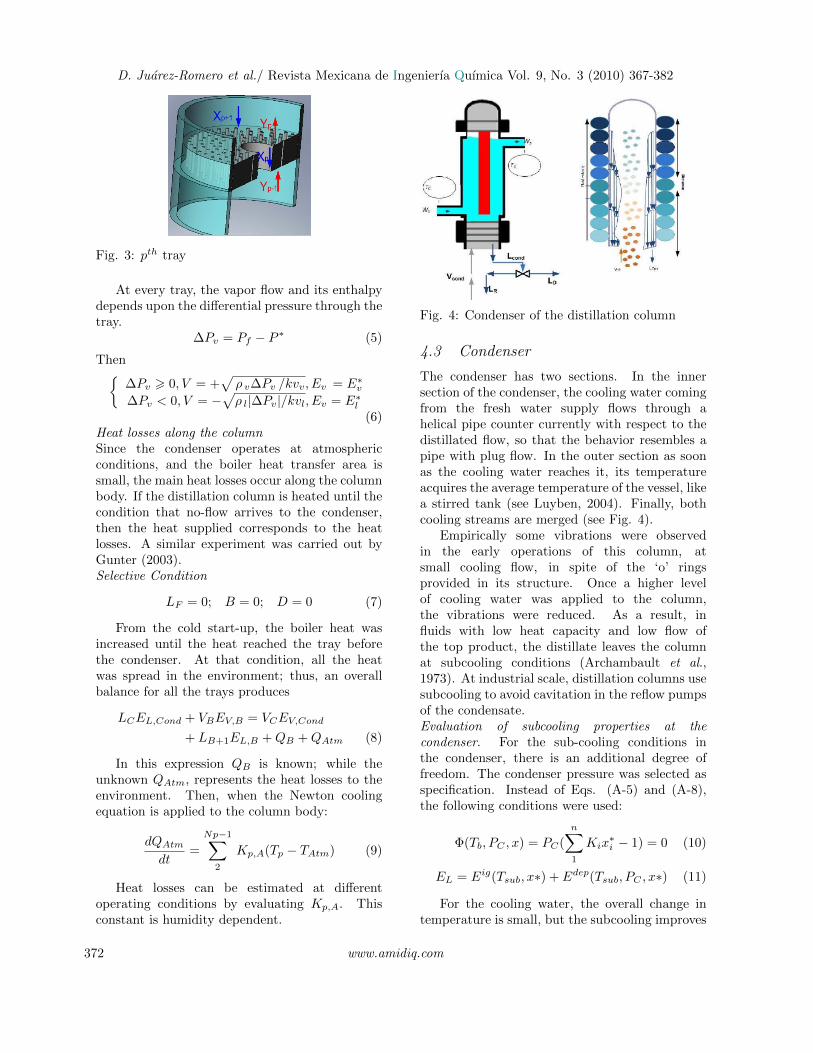
Figure: 4. Condenser of the distillation column Fig. 4: Condenser of the distillation column
4.3 Condenser
The condenser has two sections. In the innersection of the condenser, the cooling water comingfrom the fresh water supply flows through ahelical pipe counter currently with respect to thedistillated flow, so that the behavior resembles apipe with plug flow. In the outer section as soonas the cooling water reaches it, its temperatureacquires the average temperature of the vessel, likea stirred tank (see Luyben, 2004). Finally, bothcooling streams are merged (see Fig. 4).
Empirically some vibrations were observedin the early operations of this column, atsmall cooling flow, in spite of the ‘o’ ringsprovided in its structure. Once a higher levelof cooling water was applied to the column,the vibrations were reduced. As a result, influids with low heat capacity and low flow ofthe top product, the distillate leaves the columnat subcooling conditions (Archambault et al.,1973). At industrial scale, distillation columns usesubcooling to avoid cavitation in the reflow pumpsof the condensate.Evaluation of subcooling properties at thecondenser. For the sub-cooling conditions inthe condenser, there is an additional degree offreedom. The condenser pressure was selected asspecification. Instead of Eqs. (A-5) and (A-8),the following conditions were used:
Φ(Tb, PC , x) = PC(
n∑1
Kix∗i − 1) = 0 (10)
EL = Eig(Tsub, x∗) + Edep(Tsub, PC , x∗) (11)
For the cooling water, the overall change intemperature is small, but the subcooling improves
372 www.amidiq.com

D. Juarez-Romero et al./ Revista Mexicana de Ingenierıa Quımica Vol. 9, No. 3 (2010) 367-382
purity of the distillate, at the expense of reducingits yield. Gorak (2008) recommends using someheating between the condensate and the reflowto reduce subcooling, since the behavior reducesdistillation performance, in a similar way as whenthe feeding stream is placed at an incorrecttemperature. The condenser equations are:Mass balance
For a parallel array in the helical pipe andjacket sections, the flow is given by
Ww = Whl +Wjc (12)
∆Phl = ∆Pjc = kV 1W 2hl
ρhl= kV 2
W 2jc
ρjc= ∆PT
(13)
W 2hl =
kv1
kv2W 2shl, thenWhl =
√kv1
kv2Wjc (14)
Energy balance
WwCp(Tw,out−Tref ) = WhlCp(Thl,out − Tw,in)+
WshCp(Tjc,out − Tw,in) (15)
MhlCpwdThl,outdt
=WhlCpw(Tw − Thl,out)
+QD−hl − Qsh−hl (16)
MjcCpwdTjc,outdt
= WshCpw(Tw,in−Tjc,out)−Qjc−hl(17)
QD−Hl = UAhlLMTD(TD ,in, TD,out, Thl,in, Thl,out)(18)
Qjc−hl = UAsh(Thl,ave − Tjc,ave) (19)
This dynamical model of the condenserprovides a more accurate representation of thecolumn. A heat transfer with two layers can berepresented as in Lienhard and Lienhard, (2002):
K1dT
dt= K2T +K3 (20)
then
τ2d2Twdt2
+ τ1d1Twdt1
+ τ3Tw + τ4 = 0 (21)
Thus, given the configuration of the condenser, thedynamics of the cooling water temperature has a2nd order behavior, with two different negative
eigenvalues, associated with the slow and fastdynamic in the cooling temperature.
The actual configuration provides not only aneffective cooling (since the helical pipe providesa large heat transfer area, and a turbulent flowwhich increases the overall heat transfer coefficientU), but also gives a response which regulatessudden changes from the distillate flow (sincethere is a fast cooling flow in the helical pipe), andit maintains stability (since sudden changes in theinput distillate are eventually compensated by thecooling jacket). This configuration is especiallysuited for sudden changes in the reflow rate whichare caused by the opening/closing pulses of thereflow valve. For this vertical condenser, theoutput flow dynamics is highly dependent on theenergy transferred and its geometry.
4.4 Structure of the differential algebraicequations
The differential variables xd are mass, energy andcomposition per tray. The algebraic equationsxa are temperature and pressure per tray. SeeAppendix A. The general form for every tray, p is:
dxddt
= fp,j(t, xd, xa, u), j = 1, .., 3 (22)
0 = gp,j(t, xd, xa, u), j = 4, 5 (23)
4.5 Solution method for the differentialalgebraic equations
The system of Eqs. (22)-(23) is solved bythe odes23t code of Matlab. This code is animplementation of the Gear method with variabletime step, suited for a Differential-AlgebraicEquations for moderate stiffness, required duringcolumn pressurization or pressure loss, whichproduce fluctuations in vapor flow. Maximum of3rd order of approximation was specified. TheJacobian of this system of equations was evaluatednumerically. Relative and absolute toleranceswere used in the estimation of local error (10−4
and 10−6). The steady state was obtained byregulating boiler and condenser levels in thedistillation model. At every successful time step,the operating conditions were modified.
During the startup, or during sudden heat ofthe boiling at low reflux, trays holdup is small.
www.amidiq.com 373

D. Juarez-Romero et al./ Revista Mexicana de Ingenierıa Quımica Vol. 9, No. 3 (2010) 367-382
Table 2. Qualitative comparison with respect to other models
Gani (1986) Gunter (2003) This Work
Equilibrium Equation of state Polynomialapproximation, basedon Van Laar activitycoefficients
SVPR equation ofstate
Balance equations Mass, composition, energy Constant molar hold up.Constant vapor flow
Mass, energy,composition,Pressure withvarying hold andliquid and vapor flow
Boiler Geometry not specified Geometry not specified Boiling and storagevessels
Tray General tray hydraulics Francis equationMurphree efficiency
Francis equationMurphree efficiency
Condenser Geometry not specified Geometry not specified Coil and Jacketsection
Operatingconditions
Continuous saturation Continuous saturation Semi-continuousand continuous.Saturation andsubcooling
EnvironmentalConditions
Not specified Estimated heat losses Measuredatmospheric andinlet conditionsand Heat transfermodeled
Solution ODE ODE DAE
When the holdup of a tray is small, its heattransfer is very fast, while pressure and vaporflow also changes fast; as a result, variable stepmethods use very small time steps.
Table 2 shows the qualitative comparison withrespect to other models.
4.6 State space model
Given the set of measurements, Boiler Pressure,Tray Temperature,
y = h(t, xa, xd, u) (24)
The state space model required for control isobtained by Taylor approximation of the DAEsystem (eqns. 22, 23), and eliminating thealgebraic variables.
df =
(df
dxd− df
dxa
(dg
dxa
)−1dg
dxd
)∆xd
+
(df
du− df
dxa
(dg
dxa
)−1dg
du
)∆u
+
(df
dv− df
dxa
(dg
dxa
)−1dg
dv
)∆v (25)
dh =
(dh
dxd− dh
dxa
(dg
dxa
)−1dg
dxd
)∆xd
+
(dh
du− dh
dxa
(dg
dxa
)−1dg
du
)∆u
+
(dh
dv− dh
dxa
(dg
dxa
)−1dg
dv
)∆v (26)
df represents the linearized approximation forstate variables, dh represents the linearizedapproximation for measurements, u represents theinput vector (reflow, heat to the reboiler, coolingwater flow to the condenser), and v represents thedisturbances vector (environmental temperature).
This approximation relays in the assumptionthat the DAE is index 1. This is achieved bythe structure of the DAE and the consistentinitial conditions used. The numerical derivativesalso require continuity which is achieved by the“smoothening” of the pressure drop term.
374 www.amidiq.com

D. Juarez-Romero et al./ Revista Mexicana de Ingenierıa Quımica Vol. 9, No. 3 (2010) 367-382
Table 3. Range of operating conditions
Property Value
Atmospheric pressure 87.0 KPaAtmospherictemperature
27.5 - 32.8 ◦C
Differential pressure 0 - 5.0 KPaComposition in reboiler 0.59 mol
(Methanol)Feed flow 0Heat supplied toreboiler
100-2500 W
Murphree efficiency 0.95-0.97Cooling water flow 6.667 l/minBoiler hold up 60.36- 80.85 mol
(3.0 - 4. l )Heating vessel hold up 10.05-17.00 mol
(0.5-0.85 l)Tray hold up 0.4 - 0.5 molCondenser hold up 0.4 - 5.0 mol
Finally,∂g
∂u= 0, for the manipulated variables in
this model.
5 Dynamic experiments
Two experiments are present to corroborate thevalidity of the model. Feeding tests have been
delayed due to a malfunction in the feeding heatsystem. Table 3 shows the range of the operatingconditions used.
Test 5.1. Startup with further heat reduction
The behavior of the distillation model is testedusing a change in the heat supplied to the boileraccording to the profile shown in Table 4. Feedingflow is zero. Heating changes and their effects ontray temperatures are shown in Fig. 5.
Boiling starts shortly after the reboiler dutywas applied. The time response of the model andthe experimental data are similar, 1 min.
For the given composition in the reboiler themixture bubble point is 64.4 ◦C, obtained byAspen-Plus v7.1 (Aspen Technology, 2009). Atthe given load of heat to the reboiler, the time toarrive to this condition is 5.79 min, and 0.97 minif only the heating vessel is accounted.
Table 4. Profile of heat to reboiler
Time (min) QB (J/ min)
1.01 51,20012.10 38,40017.14 25,60022.18 10,200
3
Figure 5. Temperature response of Distillation column to heat supplied in boiler.
a) Profile of heat supplied to the boiler
b) Measured temperature (thin line), predicted temperature (thick line)
Fig. 5: Temperature response of distillation column to heat supplied in boiler. a) Profile of heat suppliedto the boiler b) Measured temperature (thin line), predicted temperature (thick line).
www.amidiq.com 375

D. Juarez-Romero et al./ Revista Mexicana de Ingenierıa Quımica Vol. 9, No. 3 (2010) 367-382
The trend of the steady state is differentfor computed and experimental results. Thisdeviation in bubble temperature is possiblydue to the location of the temperature sensorinside the boiler, or purity of mixture. Anaccurate prediction of temperature is particularlyimportant when the composition is estimated fromtemperature measurements.
When the boiling heat is increased, thetemperature of the boiling vessel is also increaseduntil the mixture arrives to its bubble point. Thistemperature is maintained even if a heat reductionoccurs at t = 12.0 min, because of the largeholdup of the storage vessel. A further reductionof the heat reduces the vapor flow. During thistransient the tray pressure and flow are oscillatory.A further reduction of the heat after t = 25 minreduces the temperature of the mixture and theboiling is stopped.
Test 5.2. Start-up distillate production and shut-down
The profile of the heat supplied to the reboileris shown in Table 5. Fig. 6 shows the profile of theheat supplied to the reboiler and the fraction ofthe pulses for the reflow. The distillation column
operates near to full reflow. After t = 86 min thefraction of reflow is set to 0.94, after t = 127, itis set to 0.88, and after t = 179 it is set to 0.79.The cooling water is kept within a range of 6.4-7.5 l/min. The environmental temperature was30.3◦C at the beginning of the test, and 26.1◦C atthe end of the test. No feeding flow is supplied.
Fig. 7 shows the experimental temperatureprofile along the column. Boiler starts at t = 17min. As the vapor mixture ascends, other traysarrive to their bubble point condition. Afterthe vapor arrives to the condenser, the reflowrefreshes the trays. As the reflow is reduced, thetemperature of the trays increases. After t = 202,when the heat to the reboiler is reduced, the traysbecome cooler; further reduction of heat to boilerat t = 247 stops boiling. After this condition thetrays become cooler since they do not receive anysteam.
Table 5. Profile of heat to reboiler
Time (min) QB (J/ min)
0 45,000202.1 30,000236.9 25,740247.3 15,020
3
0 50 100 150 200 250 30015
20
25
30
35
40
45
Time min
He
at t
o r
eb
oile
r K
J/m
in
0 50 100 150 200 250 3000.75
0.8
0.85
0.9
0.95
1
Time min
Fra
ctio
n o
f pu
lse
s fo
r R
eflo
w
Figure 6. Heat supplied to reboiler and fraction of pulses for Reflow in test 5.2
Fig. 6: Heat supplied to reboiler and fraction of pulses for reflow in test 5.2
376 www.amidiq.com

D. Juarez-Romero et al./ Revista Mexicana de Ingenierıa Quımica Vol. 9, No. 3 (2010) 367-382
3
0 50 100 150 200 250 30030
35
40
45
50
55
60
65
70
75
Tra
y T
em
pe
ratu
re o
C
Time min
0 50 100 150 200 250 30026
28
30
32
Co
olin
g W
ate
r T
em
p. o
C
Time min
2
4
5
7
910
11
Boiler
Output
Input
Figure 7. Profile of temperatures along the distillation column. Top temperatures
correspond to the Trays. Bottom Temperatures correspond to cooling water.
Fig. 7: Profile of temperatures along the distillation column. Top temperatures correspond to the Trays.Bottom Temperatures correspond to cooling water.
4
0 50 100 150 200 250
25
30
35
40
45
50
55
60
65
70
Time min
Tem
pe
ratu
re o
C
Boiling Vessel
Storage Vessel
Top Tray Condenser
Condenser Output
Figure 8. Modeled Profile of Temperatures in the boiler and in the condenser. Fig. 8: Modeled profile of temperatures in the boiler and in the condenser.
In this figure, it is also observed that whensteam arrives to the condenser, cooling waterbecomes warmer. The difference between inputand output cooling water is around 1◦C. As thereflow is reduced, output temperature is reduced,since the cooling stream receives less heat.
Fig. 8. presents the modeled temperaturefor: the boiler container, the storage vessel, thetray before the condenser, the condenser, andthe condenser output. The estimated time forthe boiling vessel is 12.5 min. The range oftemperatures is similar to the experimental data,
www.amidiq.com 377

D. Juarez-Romero et al./ Revista Mexicana de Ingenierıa Quımica Vol. 9, No. 3 (2010) 367-382
4
0 50 100 150 200 250 30030
35
40
45
50
55
60
65
Time min
Te
mp
oC
Condenser
Top Tray
Coil
Jacket
Figure 9. Modeled Temperatures along the condenser, and cooling circuit Fig. 9: Modeled temperatures along the condenser, and cooling circuit.
4
0 50 100 150 200 250 3000
0.2
0.4
0.6
0.8
1
1.2
1.4
Liq
uid
flo
w, M
ol/m
in
Time
0 50 100 150 200 250 300-0.2
0
0.2
0.4
0.6
0.8
1
1.2
1.4
Va
po
r flo
w, M
ol/m
in
Time
BottomTray
BottomTray
Top Tray
Top Tray
Figure 10. Liquid and Vapor Flow behavior in top and bottom tray
Fig. 10: Modeled liquid and vapor flow behavior in top and bottom tray.
378 www.amidiq.com

D. Juarez-Romero et al./ Revista Mexicana de Ingenierıa Quımica Vol. 9, No. 3 (2010) 367-382
but the experimental results describe a fastercooling in the reboiler when the boiling heat isreduced. The condensate output temperature(only estimated) is very sensible to changes of heatreduction.
Fig. 9 presents the calculated profile oftemperatures in the condenser and cooling water.The jacket temperature is cooler and more stablethan the coil temperature. The effect heatreduction is appreciated more clearly after t =206, when boiler heat is reduced.
Fig. 10 shows the calculated behavior of liquidand vapor flows at the bottom and at the toptray. The liquid flow increases from the initialconditions. The changes in the bottom tray aresmoother than in the top tray. At t = 10 minthe condenser receives vapor from the top tray.The vapor flow initially increases very fast. Aftert = 40 min the vapor flow increases steadily untilt = 200 min, when the boiling heat decreases.At this condition, the vapor flow decreases. Theresponse of the liquid flow to the boiling heat isslower, compared with the response of vapor flow,and it is also smoother.
We observed that the use of sub-coolingconditions provides a solution more stable thanthe use of saturation conditions in the condenser.When the same transient is executed including thesub-cooling, the oscillations are reduced.
6 Summary of results
The following paragraphs describe thequantitative results.
Boiler. The model of the boiler vessel and thestorage vessel reduces the estimated boiling start-up time from 6-20 min to 1-6 min (according tothe amount of reboiler heat). Adequate estimationof boiler holdup is important for the purity of theproduct, since higher boiling time drags the heavycomponents in the distilled product.
Column Body. The column model takes intoaccount the heat losses. It has been found that15 - 17% of the heat is lost in the environment forthe given mixture.
Condenser. A model of a double section for thecondenser was proposed. This array is representedby a second order. It promotes an agile responseand, at the same time, it reduces oscillations in thecondenser temperature of the distillation column.Models without this consideration require a large
mass-inertia to maintain stability under low loadsof the column; but large mass-inertia causes a slowresponse. The cooling water changes around 1 ◦C;but it produces a subcooling of 15-18 ◦C at thegiven operating conditions. At these conditionsthe estimation of concentration from temperaturerepresents a deviation of more than 10%.
Dynamic transients. The description of the semi-continuous stage is required for the consistentevaluation of the distillation process equationsfrom start-up to continuous operation. Theseequations were solved by a DAE integrator.
Conclusions
A detailed model which takes into accountthe specific configuration of the boiler and thecondenser was adapted to reduce plant/modelmismatch of the distillation column. Theconfiguration of the reboiler affects estimationof the vapor flow leaving from the reboiler. Amodel without this consideration has a narrowapplication, or it produces a time lead in itsresponse.
To represent start-up and equilibriumconditions in trays, a formulation which preservescontinuity and consistency of the solution of statevariables was proposed. Stability is assured inthe semicontinous range by the approximationof the pressure drop, and accuracy is assured inthe continuous range by the description of thethermodynamic and configuration.
Monitoring additional operating conditionswas relevant to improve the accuracy of the model.
Statistical analysis is required to tunesome dynamics-related parameters to fit overalldistillation column prediction; thus, this modelbecomes adequate for a model-based predictivecontrol.
Acknowledgements
The remarks of the reviewers were relevant toimprove the precision of the statements in thiswork. They are appreciated.
Nomenclature
A areaa parameter of the equation of stateB boiler container, boiler flow
www.amidiq.com 379

D. Juarez-Romero et al./ Revista Mexicana de Ingenierıa Quımica Vol. 9, No. 3 (2010) 367-382
B parameter of the equation of stateCp heat capacityD distillated flowE energye errorF feedf fugacityg acceleration of gravityh heightK constant, equilibrium constantk binary interaction parameterKv valve constantL liquid flowl binary interaction parameterM mass hold upMw molecular weightP pressureQ heatr prescribed trajectory of outputst timeu manipulated variableU overall heat transfer coefficientV vapor flowW control weights, cooling water flowx liquid compositiony measured variables, vapor compositionz feed composition, differential variables
Greek symbols
∆ incrementρ densityϕ hold up effectivenessη Murphree tray efficiencyε small numberτ dynamic related constantΦ function
Subscripts
a algebraicb boiler vesselB bubble pointC condenserD distillatedd differentialEff effectivef condition at the bottom of the trayF feedingH hydraulici componentL liquidM mixtureJk jacket
Hl helical pipeP tray numberSub subcoolingv valveV vaporWer weirH2O water
Superscripts
∗ equilibriumId ideal gasDep departure
References
Agachi P. S., Nagy Z.K., Cristea M.V., Imre-Lucaci A. (2007) Model Based control CaseStudies in Process Engineering. Wiley-VCH
Alpbaz M., Karacan S., Cabbar Y., HopogluH. (2002). Application of model predictivecontrol and dynamic analysis to a pilotdistillation column and experimentalverification. Chemical Engineering Journal88, 163- 174.
Aspen Technology (2009) Aspen Plus v 7.1,Aspen Dynamics
Archambault J.P., Jaufrret JP., Luyben W.L.(1973). An Experimental Study of theControl of Condensate Subcooling in aVertical Condenser. AIChE Journal 19, 923-928.
Benett D.L, Agrawal R., Cook P.J. (1983). NewPressure Drop Correlation for Sieve TrayDistillation Columns. AIChE Journal 29,(3), 434-442
Biegler L., Grossman I., Westerberg A.(1997). Systematic Methods for ChemicalEngineering Design. Prentice-Hall
Cingara A., Jovanovic M. (1990). AnalyticalFirst - Order dynamic model of binarydistillation column. Chemical EngineeringScience 45, (12), 3585-3592.
Dutta S., Gualy R. (2000). Robust ReactorModels. Chemical Engineering ProgressOct, 37-51.
Eden M. R., Koggersbol A., Hallager L.,Jorgensen S. B. (2000). Dynamics andcontrol during startup of heat integrated
380 www.amidiq.com

D. Juarez-Romero et al./ Revista Mexicana de Ingenierıa Quımica Vol. 9, No. 3 (2010) 367-382
distillation column. Computers & ChemicalEngineering 24, 1091-1097.
Gani R., Ruiz C. A., Cameron I.T. (1986). AGeneralized Model for Distillation Columns-I Model Description and Applications.Computers & Chemical Engineering 10, (3),181-198.
Gunter A.M. (2003) Dynamic MathematicalModel of a Distillation Column. Ph.D.Thesis, University of Tenesse, Chattanooga.
Kister H.Z. (2002) Can we believe the simulationresults? Chemical Engineering Progress, 52-58.
Lee J. H. (1998) Modeling and Identificationfor Nonlinear Model Predictive Control:Requirements, Current Status and FutureResearch Needs, chapter in Nonlinear ModelPredictive Control, Volume 26 of Progressin Systems and Control Theory Series,Birkhauser Verlag, Basel, Switzerland.
Lienhard J. H., Lienhard J. H. (2002). A HeatTransfer TextBook. 3rd Ed, PhlogistonPress, Cambridge Mass.
Luyben W.L. (2004) Quantitative Comparison ofTemperature control of Reactors with JacketCooling or Internal Cooling Coils. Industrial& Engineering Chemistry Research 43, 2691-2703.
Martınez-Soria C. (2001) Simulacion de ladestilacion etanol. Agua auxiliado por unabomba de calor por compresion mecanica devapor. B. Sc. thesis, FCQI, UAEM
Office of Industrial Technologies, Departmentof Energy, (Feb 2001) Distillation ColumnModeling Tools http://www.chemicalvision2020.org/pdfs/industry.pdf
Prausnitz J.M., Eckert C.A., Orye R.V.,O’Connell J.P. (1967) Computer calculationfor multiphase Liquid-Vapor Equilibria,Prentice Hall.
Rossiter J. A. (2003) Model Based PredictiveControl- a Practical Approach, CRC Press.
Ruiz C.A., Cameron I.T., Gani R. (1988). AGeneralized Model for Distillation Columns-III Study of startup Operation. Computers& Chemical Engineering 12, (1), 1-14.
Stephan K., Hildwein H. (1987). RecommendedData of Selected Compounds and BinaryMixtures, Vol IV parts 1+2, DECHEMA.
Stryjek R., Vera, J.H. (1986) An ImprovedPeng-Robinson Equation of State for PureCompounds and Mixtures. CanadianJournal of Chemical Engineering 64, 334-340.
Wang L., Li P., Gunter W., Wang S. (2003).A startup model for simulation of batchdistillation starting from a cold state.Computers & Chemical Engineering 27,(10), 1485-1497.
Wood R. K, Berry M.W. (1973). TerminalComposition Control of a Binary DistillationColumn. Chemical Engineering Science 28,1707?1717.
Wittgens B., Skogestad S. (2000). Evaluationof Dynamic Models of Distillation Columnswith Emphasis on the Initial Response.Modeling, Identification and Control 21, (2),83 - 103.
Yip, W. S., Marlin T. (2004) The Effect ofModel Fidelity on Real-Time OperationsOptimization. Computers & ChemicalEngineering 28, 267-280.
Appendix A. Model equationsfor the distillation column
Total mass
dM
dt= Lp+1 + Fp − Lp − Vp + Vp−1 (A.1)
Component mass balance around tray p
d(Mx)
dt= Lp+1xp+1+Fpzp−Lpxp−Vpyp+Vp−1yp−1
(A.2)Total energy balance around tray p
d(MpEp)
dt= Lp+1EL,p+1 + FpEF,p − LpEL,p
− VpEV,p + Vp−1EV,p−1 +Qp (A.3)
The equilibrium equation is obtained by equatingthe liquid and vapor fugacities at the bubble point
fL,i(T, Pb, x∗) = fV,i(T, Pb, y
∗) (A.4)
www.amidiq.com 381

D. Juarez-Romero et al./ Revista Mexicana de Ingenierıa Quımica Vol. 9, No. 3 (2010) 367-382
Φ(T, P, x) = Pb
(n∑1
Kix∗i − 1
)= 0 (A.5)
Also
n∑i
xi = 1 (A.6)
n∑i
yi = 1 (A.7)
E =Eig(T, x∗) + Edep(T, P, x∗) (A.8)
Murphree tray efficiency
yp,i = y∗p,iηV + (1− ηV )y∗p−1,i (A.9)
Hydraulic equations for the trays. The liquid andvapor flow are evaluated by
L = ρL
√heff
3
KvL(A.10)
heff = max(0, h− hwer) (A.11)
h = M/AρL
V =
√∆PρV MwVKvV
(A.12)
∆P = Pp+1 + ϕghρL − Pp (A.13)
ϕ = two-phase factor suggested by Benett et al.(1983).Condenser geometry:To provide a small discharge at small volumes, andto avoid flooding, the condenser is built in such away that flow increases rapidly as height increases.The following dependence of volume with respectto height was assumed:
V = V (h)cillinder − V (h)Truncated volume
V = πR2cillinder
(h− h3/2
href
)(A.14)
Appendix B. Equation of state
P =R · TV− b
− a
V2
+ 2 · b · V − b2(B.1)
a = 0.45724R2 · T 2
C
PCb = 0.077796
R · TC
PC(B.2)
The mixture properties are evaluated as:
aM =
N∑i=1
N∑j=1
xixjaij (B.3)
bM =
N∑i=1
N∑j=1
xixjbij (B.4)
Where
aij =√aiaj (1− kij); bij = 0.5*(bi + bj)(1− lij)
(B.5)The value of the interaction parameters for thismixture minimize the deviation in the predictionof relative volatility, kij = 0.01; lij = 0.017
The compressibility factor Z =PV
RTis
evaluated from the solution of:
Z3−(1−B)Z2+(A−2B−3B2)Z−(AB−B2−B3) = 0(B.6)
A =aMP
R2T 2; B =
bMP
RT(B.7)
The fugacity coefficient ϕi =fixiP
is obtained from
lnϕi =bibM
(Z − 1)− ln (Z −B)
− A
2√
2B
(2 (x1a11 + x2a12)
aM− b1bM
)ln
[Z +
(1 +√
2)B
Z +(1−√
2)B
] (B.8)
The mixture enthalpy is obtained from
[E − E∗] =
∞∫v
[−T(∂P
∂T
)v
+ P
]dV +RT (Z − 1)
(B.9)also
E∗ =
[N∑i=1
Cpi (Tf − Tref )xi
]−RTref (B.10)
382 www.amidiq.com