Embed Size (px)
Citation preview
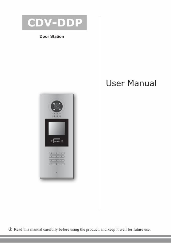
CDV-DDP
User Manual
Door Station
1 2 3
654
7 8 9
#0*
RF CARD
Read this manual carefully before using the product, and keep it well for future use.

Contents
1.Parts and Functions ...................................1
2. Terminal Descriptions ...............................1
3.Door Station Mounting ...............................2
4. System Connection ..................................3
5. Door Lock Connections .............................6
6. Door Station Configurations ......................8
7. Specification ..........................................21

1.Parts and Functions
2. Terminal Descriptions
Camera Lens
Night View LEDSpeaker
Adjustable Camera
Connectiong Port
With rainy cover
350
mm
128 mm
1 2 3
654
7 8 9
#0*
RF CARD
LCD Screen
ID Card Window
Digital Keypad
Microphone
123
L1
T/R -
CN-LK
T/R+
J/KMB JP-LK
Bus
SD Card Slot
EB
+E
B-
N.O
LK+
LK-
+12V
L2
123
123
• +12V:12VDCpoweroutput.• LK-(GND):Powerground.• LK+(COM):CommoncontactoftheRelay.• NO.:Normallyopencontactof theRelay(refer toDTtechnicalguideforLockconnection
detailinformations).• EB+:Exitbuttonconnectionport.• EB-:Exitbuttonconnectionport.• JP-LK:Forelectroniclocksafetytypesetting(refertoDoorStationLockConnections).• T/R-:USB-RS485communicationterminalnegative.• T/R+: USB-RS485communicationterminalpositive.• Bus(L1,L2):non-polaritybusline.
-1-

3.Door Station Mounting
1 2 3
4
7
5 6
Drill a hole and attach the rainy cover to it
Attach screws to fix the metal box
Attach the unit to the rainy cover correctlly
Attach the baffle to protect the unit from droping
The last view for all mounting
The view for rainy cover after mounted
Adjust the camera angle and attach the metal to the panel and wire correctly.
Camera angle
42mm
147mm
395m
m
-2-

4. System Connection
Basic IN-OUT Wiring:
Code=1, DIP-6=off
Code=31, DIP-6=off
Code=32, DIP-6=on
1 2 3
654
7 8 9
#0*
RF CARD
1 2 3 4 5 6
ON
1 2 3 4 5 6
ON
85~260AC
DPS PS5
1 2 3 4 5 6
ON
CALL
UNLOCK
TALK/MON
IN-USE
CALL
UNLOCK
TALK/MON
IN-USE
CALL
UNLOCK
TALK/MON
IN-USE
ID Code=0(Please refer to section 6->part 3(About Debug Tools)->Basic Tools Detail(table 2->ID Code) in details)
-3-

Basic Star Wiring:
ID Code=0 1 2 3
654
7 8 9
#0*
RF CARD
1 2 3 4 5 6
ON
1 2 3 4 5 6
ON
1 2 3 4 5 6
ON
1 2 3 4 5 6
ON
61 2 3 4 5 6
ON
Code=32, DIP-6=on
1 2 3 4 5 6
ON
Code=30, DIP-6=on
1 2 3 4 5
ON
Code=31, DIP-6=on
1 2 3 4 5 6
ON
Code=29, DIP-6=on
Code=4, DIP-6=on
Code=2, DIP-6=on
Code=3, DIP-6=on
Code=1, DIP-6=on
CALL
UNLOCK
TALK/MON
IN-USE
CALL
UNLOCK
TALK/MON
IN-USE
CALL
UNLOCK
TALK/MON
IN-USE
CALL
UNLOCK
TALK/MON
IN-USE
CALL
UNLOCK
TALK/MON
IN-USE
CALL
UNLOCK
TALK/MON
IN-USE
CALL
UNLOCK
TALK/MON
IN-USE
CALL
UNLOCK
TALK/MON
IN-USE
85~260AC
DPS PS5
OFF ON
OFF ON
DBC4
A B
C D
DBC4
A B
C D
Impedance switch
Impedance switch
DIP=on,off,off
DIP=on,off,off
-4-
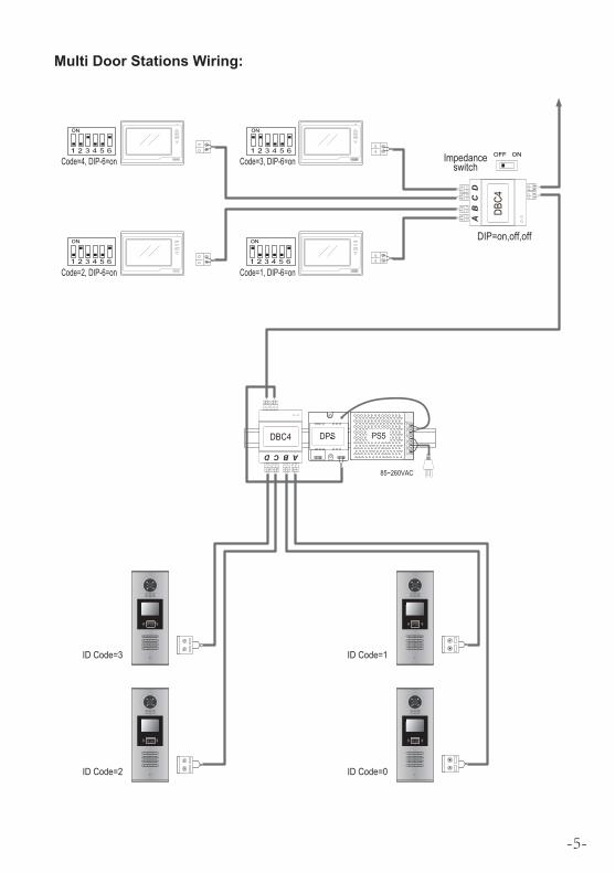
Multi Door Stations Wiring:
1 2 3 4 5 6
ON
1 2 3 4 5 6
ON
1 2 3 4 5 6
ON
1 2 3 4 5 6
ON
ID Code=1
1 2 3
654
7 8 9
#0*
RF CARD
ID Code=0
1 2 3
654
7 8 9
#0*
RF CARD
ID Code=3
1 2 3
654
7 8 9
#0*
RF CARD
ID Code=2
1 2 3
654
7 8 9
#0*
RF CARD
85~260VAC
DPS PS5
Code=4, DIP-6=on
CALL
UNLOCK
TALK/MON
IN-USE
Code=3, DIP-6=on
Code=2, DIP-6=on Code=1, DIP-6=on
CALL
UNLOCK
TALK/MON
IN-USE
CALL
UNLOCK
TALK/MON
IN-USE
CALL
UNLOCK
TALK/MON
IN-USE
DBC4
A B
C D
OFF ONImpedance switch
DIP=on,off,off
DBC4
A B C D
-5-

5. Door Lock Connections
1. Internal Power Supply ModeUsethepowerofthesystemtosupplyfortheelectroniclock,sothatthelockcanbeconnectedtothedoorstationdirectly,withoutanadditionalpowersupplyfortheelectroniclock.Notethatthedoorstationcanonlyoutput12Vdcpower,thereforethekindoflockislimited.• Theratedpowerof the lockmustbe lessthan12Vdc300mAwhenusing internalpower
supplymode• TheGNDmustconnecttothenegativeofthelock,andtheCOMconnecttothepositive.• Jumpersetto1-2positionforPower-off-to-Unlocksafetytype(Normally closed mode);
setto2-3positionforPower-on-to-Unlocktype(Normally open mode).• Ifdifferentunlocking time isneededtobeconfigured, changetheUnlock Timingon
doorstation.(Indebugstate,press[1#]-->[1]InstallerSetup-->[2]UnlockTiming)
JP_LK
12V 300mA
Jumper set to 2-3 position
+
-+12VLK - (GND)LK+(COM)N.O.EB+EB -
123
set to Normally open on the Unlock Relay mode
A. Connection for Power-on-to-Unlock type:
12V 300mA
Jumper set to 1-2 position
+12VLK - (GND)LK+(COM)N.O.EB+EB -
+
-
set to Normally Closed on the Unlock Relay mode
JP_LK
123
B. Connection for Power--off-to-Unlock type:
-6-
+
+
-
-+12VLK - (GND)LK+(COM)N.O.EB+EB -
Remove the Jumper
set to Normally Open on the Unlock Relay mode (default)
JP_LK
123
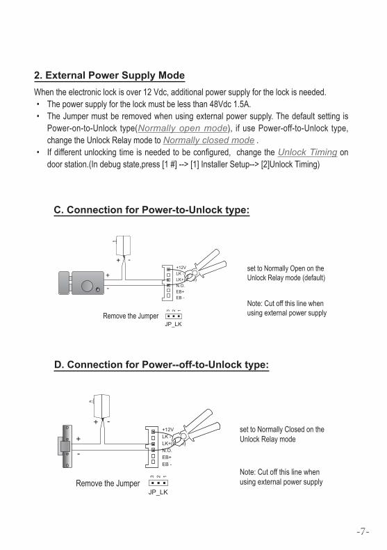
Note: Cut off this line when using external power supply
+12VLK - (GND)LK+(COM)N.O.EB+EB -
Remove the Jumper
set to Normally Closed on the Unlock Relay mode +
+
-
-
JP_LK
123
Note: Cut off this line when using external power supply
2. External Power Supply ModeWhentheelectroniclockisover12Vdc,additionalpowersupplyforthelockisneeded.• Thepowersupplyforthelockmustbelessthan48Vdc1.5A.• TheJumpermustberemovedwhenusingexternalpowersupply.Thedefaultsetting is
Power-on-to-Unlock type(Normally open mode), ifusePower-off-to-Unlock type,changetheUnlockRelaymodetoNormally closed mode.
• Ifdifferentunlockingtimeisneededtobeconfigured,changetheUnlock Timingondoorstation.(Indebugstate,press[1#]-->[1]InstallerSetup-->[2]UnlockTiming)
C. Connection for Power-to-Unlock type:
D. Connection for Power--off-to-Unlock type:
-7-

6. Door Station Configurations
1. About room code(address):RoomCode(alsocalledroomaddress)isacodeassignedtoeachmonitor,toidentifydifferentmonitors;eachmonitorhaveauniqueroomcodeinonebuildingroomCodeisstoredineachMonitor’sinnerEEPROMmemory,anddoesnotloseeventhemonitorispoweroff.
2. About Debug State:TheDebugStateisyourstartingpointforusingalltheapplicationsonCDV-DDP.
WhenDoorStationisinstandby,press'#'key
Press"2#"keytoexitoutthedebugstate.
input'9008',theninputtheAdminCode.(66666666bydefault)
DebugStatemenuislaunched
[ 9 0 0 8 ]
Please Input Password
1 2 3
654
7 8 9
#0*
RF CARD
> > D e b u g S t a t e < <
1 - # To o l s
0 - # Re d i a l
2 - # E x i t s
3. About Debug Tools:DuringworkingatDebugState,press"1#"toentertoolspage,DebugToolsoverviewsisshownasbelow:
1 . I n s t a l l e r S e t u p
2 . S e t u p
3 . C a r d M e m o r y
4 . O n l i n e M o n i t o r s
5 . O n l i n e D e v i c e s
6 . Vo l t a g e M e a s u r e
Pres NO. to select
*Back
Tools
> > D e b u g S t a t e < <
0 - # Re d i a l
2 - # E x i t s
1 - # To o l s
-8-

Item Submenu
1. Installer Setup
1.IDCode[0]2.UnlockTiming[05]3.UnlockOutput[0]4.CardMemory[0]5.DoorplateMode6.AudioOptions...7.Parameters...8.InstallerCode...9.Default...
2. Setup
1.Language[1]2.ToneSelect[03]3.ToneVolume[08]4.UnlockCode[1111]5.DisplayMode6.Clock...7.SetupCode...8.About...9.Default...
3. Card Manage
1.AddCard...2.DeleteByCard3.DeleteByM.code4.CardsInformation5.Format
4. Online Monitors Tosearchtheonlinemonitors,input themonitorcodenumbertosearch
5. Online Devices Tosearchtheonlinedoorstations.Max.4doorstationcanbesearched
6. Voltage Measure Tocheckthevoltageofthemonitor,notethatthemoni-tormustbeonline.
Table1:
-9-

Basic Tools Detail:
Item Description Factory set
IDCode
Ifonlyonedoorstationisinstalledinthisbuilding,setto0;Ifmultidoorstationsareinstalled,primarydoorstationmustbesetto0,andotherslavedoorstationsmustbesetfrom1to3.Notethatmax.4doorstationsareavailableinonebuilding
[0]Single
UnlockTiming Tosetthetimethathowlongthedoorkeepsopenwhendoorisreleased.Rangefrom01to99seconds.
[05]5seconds
UnlockOutput
Tosettheunlockmodetomatchthecorrespondinglock.Rangefrom0to1.0:Power-on-to-UnlockMode(NormallyOpenMode)1:Power-off-to-UnlockMode(NormallyClosedMode)
0
CardManage Tosetthecardlocation.Ifsetto0,thecardissavedindoorstation.Ifsetto1,thecardissavedinDT-IPC 0
DoorplateMode
Tosetthecallingmode.Ifsetto0,it'stheautomode,thatmeansthecallingwillbeactivateddirectlyafterinputting2digitscode.Ifsetto1,it'sthemanualmode,thatmeansyoushouldpress"#"buttontoacti-vatethecallingafterinputtingthecode.
[0]Automode
AudioOptions...
Tosettalkingmode,whencuttingvoiceormixedvoiceappears,setto1.DS-IMtalking:setthevoicematchingbetweenDoorStationandIndoorMonitorDS-NTtalking:setthevoicematchingbetweenDoorStationandGuardUnit
0
Parameters... Toshowtheparameters,pleaserefertotable2.1
InstallerCode... Tochangedoorstationadministratorcode [66666666]
Default...Note thisoperation is irreversible.Once restore isactivated,allparameterswill return to factorydefaultsettingexcepttheinformationofaccesscard.
Table2(InstallerSetup):
-10 -
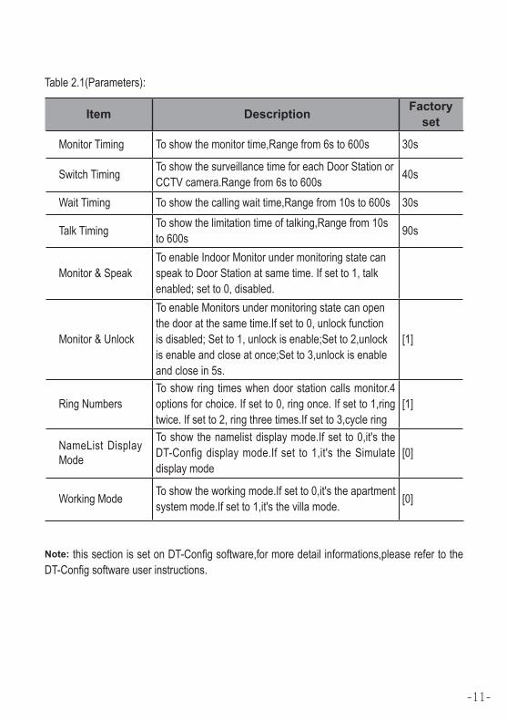
Item Description Factory set
MonitorTiming Toshowthemonitortime,Rangefrom6sto600s 30s
SwitchTiming ToshowthesurveillancetimeforeachDoorStationorCCTVcamera.Rangefrom6sto600s 40s
WaitTiming Toshowthecallingwaittime,Rangefrom10sto600s 30s
TalkTiming Toshowthelimitationtimeoftalking,Rangefrom10sto600s 90s
Monitor&SpeakToenableIndoorMonitorundermonitoringstatecanspeaktoDoorStationatsametime.Ifsetto1,talkenabled;setto0,disabled.
Monitor&Unlock
ToenableMonitorsundermonitoringstatecanopenthedooratthesametime.Ifsetto0,unlockfunctionisdisabled;Setto1,unlockisenable;Setto2,unlockisenableandcloseatonce;Setto3,unlockisenableandclosein5s.
[1]
RingNumbersToshowringtimeswhendoorstationcallsmonitor.4optionsforchoice.Ifsetto0,ringonce.Ifsetto1,ringtwice.Ifsetto2,ringthreetimes.Ifsetto3,cyclering
[1]
NameListDisplayMode
Toshowthenamelistdisplaymode.Ifset to0,it's theDT-Configdisplaymode.Ifset to1,it's theSimulatedisplaymode
[0]
WorkingMode Toshowtheworkingmode.Ifsetto0,it'stheapartmentsystemmode.Ifsetto1,it'sthevillamode. [0]
Table2.1(Parameters):
Note:thissectionissetonDT-Configsoftware,formoredetailinformations,pleaserefertotheDT-Configsoftwareuserinstructions.
-11-

Item Description Factory set
LanguageTochangelanguage.thecodeformatis4digits.Pleaserefertopart5,section10(changedoorstationlanguage)formoredetailinformations.
01
ToneSelect SelectthechimeofDoorStationincallingwaitstate,12chordtunesareavailable,keyin01to12toselect. 03
ToneVolume Adjustthetonevolumefordoorstationincalling.Rangefrom01~15 08
UnlockCode TochangeunlockcodeinCommonCodeUnlockmode,in4-digitsformat.1111isthedefaultunlockcode. [1111]
DisplayModeToselecttheDoorStationscreenmenu.Ifsetto0,thescreendisplaysthevisitor'simagewhentalking.Ifsetto1,thescreendisplaysiconswhentalking.
[0]
Clock...
Tosetdateandtime.Dateformat:ifsetto0,dateformatisDD/MM/YY,ifsetto1,dateformatisMM/DD/YY.Timeformat:ifsetto0,timeformatis24hourstandard.Ifsetto1,timeformatis12hourstandard.
SetupCode TochangetheProgramCode. [88888888]
About...
1.Hardwareversion---ToshowtheDoorStation(includingACS)hardwareinformation2.Softwareversion---ToshowtheDoorStation(includingACS)softwareinformation3.ManufactureDate---Toshowthemanufacturingdate4.DialingCounts---Toshowthecalloperationcounts5.CallsCounts---Toshowtheestablishedcallingcounts6.UnlockCounts---Toshowtheunlockoperationcounts7.StandbyVoltage---Toshowthevoltagethatthedoorsta-tioninstandby.8.WorkingVoltage---Toshowthevoltagethatthedoorsta-tioninworking.9.VideoStandard---PALorNTSCstandard10.UI_CODE---ToshowtheUIbytecountsandcheckbox11.MCM-VER---ToshowtheversionandlanguageforMCM12.Updated---ToshowtheupdatedtimeforUI
Default... RestoreallSetupparameterstofactorydefaultsetting,Pleasenotethatthisoperationisanirreversible
Table3(Setup):
-12-

Item Description Factory set
AddCard... Toaddtheusercard
DeleteByCard Todeletecardbyusercard
DeleteByM.code Todeletecardbyroomcode
CardsInformation Toshowtheinformationsaboutcards
Format Toformatinformationsaboutcards
Table4(CardManage):
4. Calling and Unlock Operation:Thedoorstationisadigitalstationwith320*240pixelsLCDscreen,colorCCDcamera,nightviewLED,anddigitalkeypad.
Visitorscancall theapartmentbydialing theFlatCode(apartmentnumber)onthekeypad.If theydon’tknowtheFlatCode(apartmentnumber), theycansearch thename liston thescreen.Ifthedoorstationisinstandby,visitorsneedtopress'9#'todisplaytheusernamelist.Press"#"keytoscrollnext/lastpage.andusekey1to8keyoneachpagetocallthedesiredflat.
ResidentscanopenthedoorbyusingtheiruniqueUnlockCode(four-digitPINcode). If thedoorstationisinstandbymode,press'#'key,theninputthefour-digitunlocktoopenthedoor.Pleaserefertopart5,section7(Howtousecodeunlockfunction)formoredetailinformation.
5. About Default Set:TheDefaultSetisveryimportant.Whenthedoorstationmissupthesettingsinanyway,themostquicklyandeasywaytosolvetheproblemistoactivatethedefaultsettingondoorsta-tion.Thedefaultsettingsalreadyhavealltherightsettingsforone-buildingsystem,thatmeansthesystemwillworknormallywithoutanyadditionalsettings..
Note:Ifthedoorstationworksasapartmentsystemmode,input01~32tocalltherelevantmon-itor.If thedoorstationworksasvillamode,input01tocall themonitorswhichitscodeisfrom00~15.Input02tocallthemonitorswhichitscodeisfrom16~31.pleaserefertotable2.1(work-ingmode)
-13-

InDebugState,press'1#'key
InToolsmenu,press'1'key
Input Installercode (66666666bydefault),thenpress"#"tosave
Press'9'key,apass-wordwillbeasked.
> > D e b u g S t a t e < <
0 - # Re d i a l
2 - # E x i t s
1 . I D C o d e . [ 1 ] 2 . U n l o c k T i m i n g [ 0 5 ]
3 . U n l o c k O u t p u t [ 0 ]
4 . C a r d M e m o r y [ 0 ]5 . D o o r p l a t e M o d e
6 . A u d i o O p t i o n s . . .7 . Pa r a m e t e r s . . .
8 . I n s t a l l e r C o d e . . .
Press No. to select
*Back
InstallerSetup
9 . D e f a u l t
1 - # To o l s
1 . I n s t a l l e r S e t u p
2 . S e t u p
3 . C a r d M e m o r y
4 . O n l i n e M o n i t o r s
5 . O n l i n e D e v i c e s
6 . Vo l t a g e M e a s u r e
Pres NO. to select
*Back
Tools
*Back
[ - - - - - - - - ]
Please Input Password
# Save
9 . D e f a u l t . . .
Press“#”,Input“8002”,theninputSetupCodeorAdminCode(88888888or66666666bydefault)
Press“2”toentertoneselectitem.
6. Change Ring Tone:Thereare12differentringtones, IfdoorstationrunsasDebugState,youcanpress[1#]-->[2]Setup-->[2]ToneSelecttoentertonesettingpage.If itrunsasNormalState,followthesesteps:
Input2digitsnumber,thenpress“#”tosavethesetting
[ 8002 ]
Please Input Password
1 2 3
654
7 8 9
#0*
RF CARD
1 . L a n g u a g e [ 1 ]
3 . To n e Vo l u m e [ 0 3 ]
4 . U n l o c k C o d e [ 1 1 1 1 ]
5 . D i s p l a y M o d e
6 . C l o c k7 . S e t u p C o d e
8 . A b o u t9 . D e f a u l t
Press No. to select
*Back
Setup
*Back
[ - - ]
( 01~12)
# Save
2 . To n e S e l e c t [ 0 3 ]2 . To n e S e l e c t [ 0 3 ]
-14-

7. Change Installer Code(administrator password):TheInstallerCodeisthepasswordtoaccessthedoorstationdebugState.ThedefaultInstallerCodeis'66666666'.NotethatiftheDefaultSethavebeenactivated,theInstallerCodewillbesettodefaultvalue.
8. How to use code unlock function:Pleaserefertothefollowingoperations:
> > D e b u g S t a t e < <
0 - # Re d i a l
2 - # E x i t s
1 . I D C o d e [ 1 ] 2 . U n l o c k T i m i n g [ 0 5 ]
3 . U n l o c k O u t p u t [ 0 ]
4 . C a r d M e m o r y [ 0 ]5 . D o o r p l a t e M o d e
6 . A u d i o O p t i o n s . . .7 . Pa r a m e t e r s . . .
9 . D e f a u l t
Press1~9 to select
*Back
InstallerSetup
1 - # To o l s
8 . I n s t a l l e r C o d e . . .
1 . I n s t a l l e r S e t u p
2 . S e t u p
3 . C a r d M e m o r y
4 . O n l i n e M o n i t o r s
5 . O n l i n e D e v i c e s
6 . Vo l t a g e M e a s u r e
Pres NO. to select
*Back
Tools
*Back
[ - - - - - - - - ]
( * * * * * * * *)
# Save
8 . I n s t a l l e r C o d e . . .
InDebugState,press'1#'key
InputanewInstallerCodeandthenpress'#'keytoconfirm
press'1' press'8'
[ - - - - ]
Please Input Password
1 2 3
654
7 8 9
#0*
RF CARD
1 2 3
654
7 8 9
#0*
RF CARD
[8017 ]i Door Open
WhentheDoorStationisinstandby,Press“#”
Ifverifiedcorrectly,dooropen
Input4digitsUnlockCodedirectly
-15-
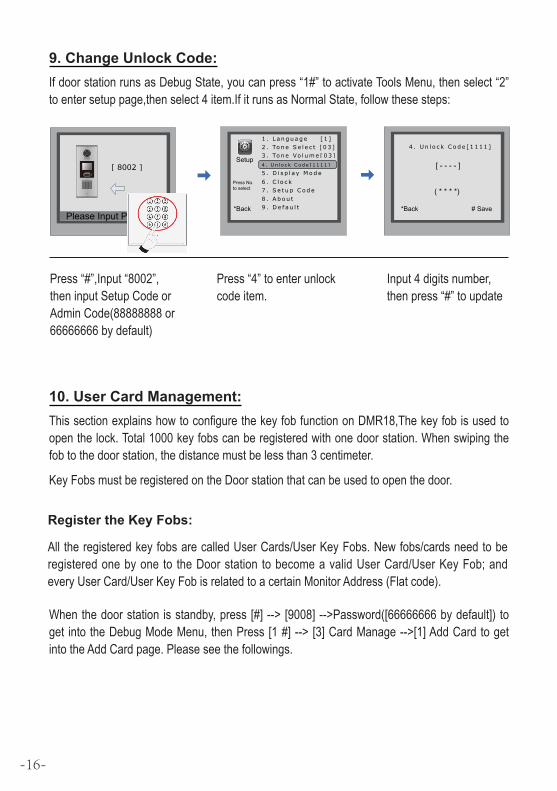
Press“#”,Input“8002”,theninputSetupCodeorAdminCode(88888888or66666666bydefault)
Press“4”toenterunlockcodeitem.
9. Change Unlock Code:IfdoorstationrunsasDebugState,youcanpress“1#”toactivateToolsMenu,thenselect“2”toentersetuppage,thenselect4item.IfitrunsasNormalState,followthesesteps:
[ 8002 ]
Please Input Password
1 2 3
654
7 8 9
#0*
RF CARD
1 . L a n g u a g e [ 1 ]2 . To n e S e l e c t [ 0 3 ]3 . To n e Vo l u m e [ 0 3 ]
5 . D i s p l a y M o d e
6 . C l o c k7 . S e t u p C o d e
8 . A b o u t9 . D e f a u l t
Press No. to select
*Back
Setup
*Back
[ - - - - ]
( * * * *)
# Save
4 . U n l o c k C o d e [ 1 1 1 1 ]
4 . U n l o c k C o d e [ 1 1 1 1 ]
Input4digitsnumber,thenpress“#”toupdate
10. User Card Management:ThissectionexplainshowtoconfigurethekeyfobfunctiononDMR18,Thekeyfobisusedtoopenthelock.Total1000keyfobscanberegisteredwithonedoorstation.Whenswipingthefobtothedoorstation,thedistancemustbelessthan3centimeter.
KeyFobsmustberegisteredontheDoorstationthatcanbeusedtoopenthedoor.
Register the Key Fobs:
All theregisteredkeyfobsarecalledUserCards/UserKeyFobs.Newfobs/cardsneedtoberegisteredonebyone to theDoorstation tobecomeavalidUserCard/UserKeyFob;andeveryUserCard/UserKeyFobisrelatedtoacertainMonitorAddress(Flatcode).
Whenthedoorstation isstandby,press[#]-->[9008]-->Password([66666666bydefault]) toget intotheDebugModeMenu,thenPress[1#]-->[3]CardManage-->[1]AddCardtogetintotheAddCardpage.Pleaseseethefollowings.
-16-

EnterAddCardmenu,andRoomCodeisasked.
InputRoomCode Readthecardtobeauthorized
Delete user cards:
Delete By Card:
InDebugState,Press[1#]-->[3]CardManage -->[2]DeleteByCardtoenterDeletebyCardpage.asshownontheright,thenshowthecardsyouwant tode-leteonebyone.
2 . D e l e t e B y C a r d . . .
* Back # Save
Show The Card
2 . D e l e t e B y C a r d . . .
* Back # Save
User
Card
Car d numbs:1 5 9 7 7 1 3 1
Show The Card
RegisteredUserCards/KeyFobscanbedeletedfromtheDoorstation,oncedoingthedeleteoperation,thecard/keyfobscannotopenthedooranymore.Theycanalsobere-registeredagaintobecomeavalidUserCard/UserKeyFob.TherearetwowaystodeleteUserCards/UserKeyFobs:
1.Deletebycard:showtheunwantedcard(s)whentheDoorstationisinDeleteCardMode
2.Deletebyroomnumber:deletealltheregisteredUserCardsrelatedtothatroomnumber.
1 . A d d C a r d . . .
* Back # Save
Please Input Room Code
[ - - ]
1 . A d d C a r d . . .
* Back # Save
Show the card
[ 0 1 ]
1 . A d d C a r d . . .
* Back # Save
[ 0 1 ]
Car d numbs : 1 5 9 7 7 1 3 1
Show The Card
User
Card
3 . D e l e t e B y M . c o d e
* Back # Save
Please Input Room Code
[ - - ]
3 . D e l e t e B y M . c o d e
* Back # Save
Updat ed
[ 0 1 ]
InDebugState,Press[1#]-->[3]CardManage -->[3]DeleteByM.Code toenterDeletebyM.Codepage.asshownon theright,thenInputtheRoomCode,press “#” toconfirm;allassoci-atedcardswillbedeleted.
Delete by Room Number:
-17-

Card information:
Format:
EnterCard Informationpage,and thescreenwilldisplaytheauthorizedUserCards count, and card read accesseventscount.
EnterCardFormatpage,apasswordwill be asked,input 8 digits installerpassword (66666666bydefault),thenpress"#"key tosave,formatoperationisactivated.allcard informationwillbecleared.
4 . C a r d s I n f o r m a t i o n
* Back # Save
Card Count: 1000
5 . Fo r m a t
* Back # Save
Please Input Password
[ - - - - - - - - ]
11. Change Door Station Language:It'sconvenienttochangetheuserinterfaceforCDV-DDP.JustputtheconfigfilestotheSDcardandbymeansofthedigitalkeypadofdoorstation,only30secondsisneededtoupdate.
L1
T/R -
CN-LK
T/R+
J/KMB JP-LK
Bus
Insert SD cardSD Card Slot
EB
+E
B-
N.O
LK+
LK-
+12V
L2
123
123
Step1: Insert theSDcardwhich iscon-tainedconfig files into theSDcardslotwhere isat thebackof thedoorstation.Refertotherightdiagram.
Step2:
IfdoorstationrunsasDebugState,youcanpress“1#” toactivateToolsMenu,select“2” toentersetuppage,thenselect1item.IfitrunsasNormalState,followthesesteps:
-18-
Language code number: [8017 ]i Download
[ 8002 ]
Please Input Password
1 2 3
654
7 8 9
#0*
RF CARD
2 . To n e S e l e c t [ 0 3 ]3 . To n e Vo l u m e [ 0 3 ]
5 . D i s p l a y M o d e
6 . C l o c k7 . S e t u p C o d e
8 . A b o u t9 . D e f a u l t
Press No. to select
*Back
Setup
*Back
[ - - - - ]
( Code Number)
# Save
1 . L a n g u a g e
4 . U n l o c k C o d e [ 1 1 1 1 ]
1 . L a n g u a g e [ 1 ]
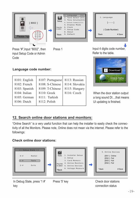
Press“#”,Input“8002”,theninputSetupCodeorAdminCode
Press1 Input4digitscodenumber,Refertothetable.
WhenthedoorstationoutputalongsoundDI...,thatmeansUIupdatingisfinished.
8101: English8102: French8103: Spanish8104: Italian8105: German8106: Dutch
8107: Portuguese8108: S-Chinese8109: T-Chinese8110: Greek8111: Turkish8112: Polish
8113: Russian8114: Slovakia8115: Hungary8116: Czech
12. Search online door stations and monitors:“OnlineSearch”isaveryusefulfunctionthatcanhelptheinstallertoeasilychecktheconnec-tivityofalltheMonitors.Pleasenote,Onlinedoesnotmeanviatheinternet.Pleaserefertothefollowings:
> > D e b u g S t a t e < <
0 - # Re d i a l
2 - # E x i t s
* Back # Save
[DS1 ] : Online[DS2 ] : Fail[DS3 ] : Fail[DS4 ] : Fail
5 . O n l i n e D e v i c e s
1 - # To o l s
1 . I n s t a l l e r S e t u p
2 . S e t u p
3 . C a r d M e m o r y
4 . O n l i n e M o n i t o r s
5 . O n l i n e D e v i c e s
6 . Vo l t a g e M e a s u r e
Pres NO. to select
*Back
Tools
InDebugState,press'1#'key
Press'5'key Checkdoorstationsconnectionstatus
Check online door stations:
-19-

> > D e b u g S t a t e < <
0 - # Re d i a l
2 - # E x i t s
* Back # Save
(Search Range)
[ - - ] ~ [ - - ]
4 . O n l i n e M o n i t o r s
* Back # Save
[ 01 ] Online[ 02 ] Online[ 03 ] Online[ 04 ] Fall[ 05 ] Online
4 # . O n l i n e M o n i t o r s
1 - # To o l s
1 . I n s t a l l e r S e t u p
2 . S e t u p
3 . C a r d M e m o r y
4 . O n l i n e M o n i t o r s
5 . O n l i n e D e v i c e s
6 . Vo l t a g e M e a s u r e
Pres NO. to select
*Back
Tools
InDebugState,press'1#'key
Press'4'key Input2digitsmonitorcode
SearchRange:inputthemonitoraddress.Forexample,inputtherangefrom01to05.Youwillseetheconnectionstatusoftheselectedmonitors.
13. Namelist function:ThedoorstationisdesignedtohavedigitalkeypadandbigTFTscreen.ItsnamelistwasshownonthescreenandcustomercandothecallingoperationthroughthedigitalkeypadguidedbyNamelistonthescreen.2typesofnamelistcanbeshownonthescreen:DT-ConfignamelistandSimulatenamelist.
Enter namelist page:
Check online monitors:
Send namelist to monitors
Press'9#'instandbymodetodisplaytheusernamelist.Press"#"keytoscrollnext/lastpage.andusekey1to8keyoneachpagetocall theflatyouwant.Pleaserefer to theDT-Configsoftwareuserinstructionsforconfigurethenamelist.
Thenamelistcanbesenttomonitorsbydoorstationdirectly.Connectthedoorstationandmon-tiorscorrectlytothesystem.Thenpress#8012instandbymode,andinputpassword(66666666bydefault)tosendnamelisttoallthemonitors.
-20-

7. Specification
● Power supply: DC24V(Powered by DPS)
● Camera Lens : 1/4 ACS 4T image sensor with DSP processor
● Power consumption: Standby 3W;Working status 9W
● Screen: 3.5 inch TFT
● Resolution: 320(R, G, B)X240 pixels
● Video signal: CCIR/EIA Optional
● Wiring: 2 wires, non-polarit
-21-

Model: CDV-DDP
The design and specifications can be changed without notice to the user. Right to interpret and copyright of this manual are preserved.