Embed Size (px)
Citation preview
RF Technology for EJX/YTA Series Wireless Transmitters in Hazardous Areas
Yokogawa Technical Report English Edition Vol.55 No.2 (2012)
RF Technology for EJX/YTA Series Wireless Transmitters in Hazardous AreasSatoshi Mochizuki *1
Recently, demand for field wireless devices that can be used in hazardous areas is increasing. Detachable antennas and extension cables are desirable to ensure good communication conditions if numerous metallic pipes, which can interrupt wireless communications, are present in the area. To monitor wellheads, high-gain antennas are required for long-distance communication because such areas are remotely distributed. To satisfy these demands, Yokogawa has developed a key component by combining high-frequency and explosion proof technologies. This enables antennas and their extension cables to be replaced in hazardous areas. This paper outlines this key component.
INTRODUCTION
In recent years, more field wireless devices have been used in hazardous areas.
Meanwhile, in plants that are usually recognized as hazardous areas, there are numerous metallic tanks and pipes that easily shield or reflect radio waves, as discussed later, thus resulting in a poor environment for wireless communication. Yokogawa’s field wireless differential pressure transmitters and temperature transmitters conform to explosion proof standards and ensure superior communication reliability even in such an environment, based on the design policy of reliable radio as described in “Reliability and Stability of Field Wireless” in this special issue. However, the field conditions differ in each plant and field wireless devices cannot be installed arbitrarily. So in some cases communication quality cannot be fully ensured.
To resolve this problem, an effective solution is to expand the installable location of antennas. One example is shown in Figure 1, where an antenna is installed with an extension
cable. Such installation is usually difficult in hazardous areas because of the many requirements of explosion proof standards.
Figure 1 External view of the connection of EJX wireless transmitter with its antenna
Yokogawa developed a key component by combining high-frequency and explosion proof technologies, which
Wireless EJX
Extension cable
Antenna
19 57
*1 Business Planning Division, Industrial Automation Marketing Headquarters

RF Technology for EJX/YTA Series Wireless Transmitters in Hazardous Areas
Yokogawa Technical Report English Edition Vol.55 No.2 (2012) 2058
is incorporated in its f ield wireless devices and enables antennas to be replaced in hazardous areas. This component also satisfies the customer request to reduce the number of repeaters and curb the total power consumption and cost of f ield wireless systems. This paper describes this key component.
NECESSITY OF REMOTE ANTENNAS
Plants to be installed with field wireless devices are often built of materials that can ref lect, scatter, diffract, refract, or shield radio waves, such as metal and concrete. Field wireless devices cannot be installed arbitrarily because they must monitor and control certain targets in a limited area. If these devices are installed in a place surrounded by metallic components or the like as shown in Figure 2, they would not be able to communicate directly. In particular, differential pressure transmitters are usually installed near the ground, thus their wireless communication may be affected by reflection from the ground. Antennas that can be replaced or moved to the optimum position for communication in a plant (hereinafter referred to as “remote antennas”) will improve the stability of wireless communication.
Figure 2 Example of installation environment for field wireless devices
In addition, a remote antenna increases the freedom to select communication routes for transmitting and receiving signals between field wireless devices, routers, and gateways, etc. This can help avoid placing an excessive network load on certain field wireless devices, prevent data traffic problems, and extend battery life.
Therefore, remote antenna technologies can improve the reliability of wireless communication and reduce the number of repeaters. However, to extend remote antennas with extension cables or replace them in hazardous areas, the complicated requirements of explosion proof standards must be overcome.
MEANS TO ACHIEVE REMOTE ANTENNAS
Mounting a radio f requency (RF) connector at a high-frequency output port of a field wireless device and connecting a coaxial cable to the connector is not enough to replace an antenna or change its installation location in
hazardous areas. Additional means is required not only for satisfying high-frequency properties but also for overcoming many requirements of various explosion proof standards. It would be effective if a single component could resolve all of the explosion proof and high-frequency requirements and convenient if such a component could be used in all models. It is also desirable that the component be inexpensive. Taking into considerations the following points, Yokogawa has developed a key component.
Points to be Considered Risks to be avoided:
• Effects on the communication distance caused by temperature dependence of capacitors in signal-return separated circuits using chip capacitors, chip coils and so on with a lumped constant
• Effects on the communication distance caused by change in load on an antenna, its extension cable, and a component connected to both ends of a capacitor
• Effects on the communication distance caused by change in the internal structure of a chip capacitor
Cost increase due to the mounting of a high-pass filter to remove out-of-band noise
Decrease in output level and resulting degradation of wireless communication distance due to increased in-band transmission loss caused by the noise rejection filter
Transmitting radio signals without guaranteed design
RF Key Component for Remote AntennasTo develop remote antennas that can be used in hazardous
areas, a high frequency equivalent circuit shown in Figure 3 was studied. When this circuit is configured with discrete parts, the behavior of parasitic elements characteristic of high frequencies must be verified for every part to ensure the output characteristics of the circuit. In this case, however, guaranteed design is practically impossible because high frequency characteristics depend largely on the physical st ructure and mater ials inside each par t and changes (modification) in the structure of replacement parts in the future is unpredictable. Therefore, the design assurance was achieved by adopting a distributed constant circuit as shown in Figure 4.
A microstr ip line st ructure is of ten used for high frequency signal transmission. This structure is composed of the high frequency signal line and the ground (GND) line comprising the return circuit for the signals. A stripline structure using the return circuit as reference or a coplanar structure are also well known for achieving a stable high frequency characteristic.
However, a single circuit with a general structure for high frequency transmission systems as described above cannot solve all items described in “Points to be considered.” Therefore, a coupled line structure was adopted for signal t ransmission. As a result, both highly eff icient power transmission and highly stable signal transmission were successfully accomplished. Figure 4 shows a distributed
RF Technology for EJX/YTA Series Wireless Transmitters in Hazardous Areas
Yokogawa Technical Report English Edition Vol.55 No.2 (2012)
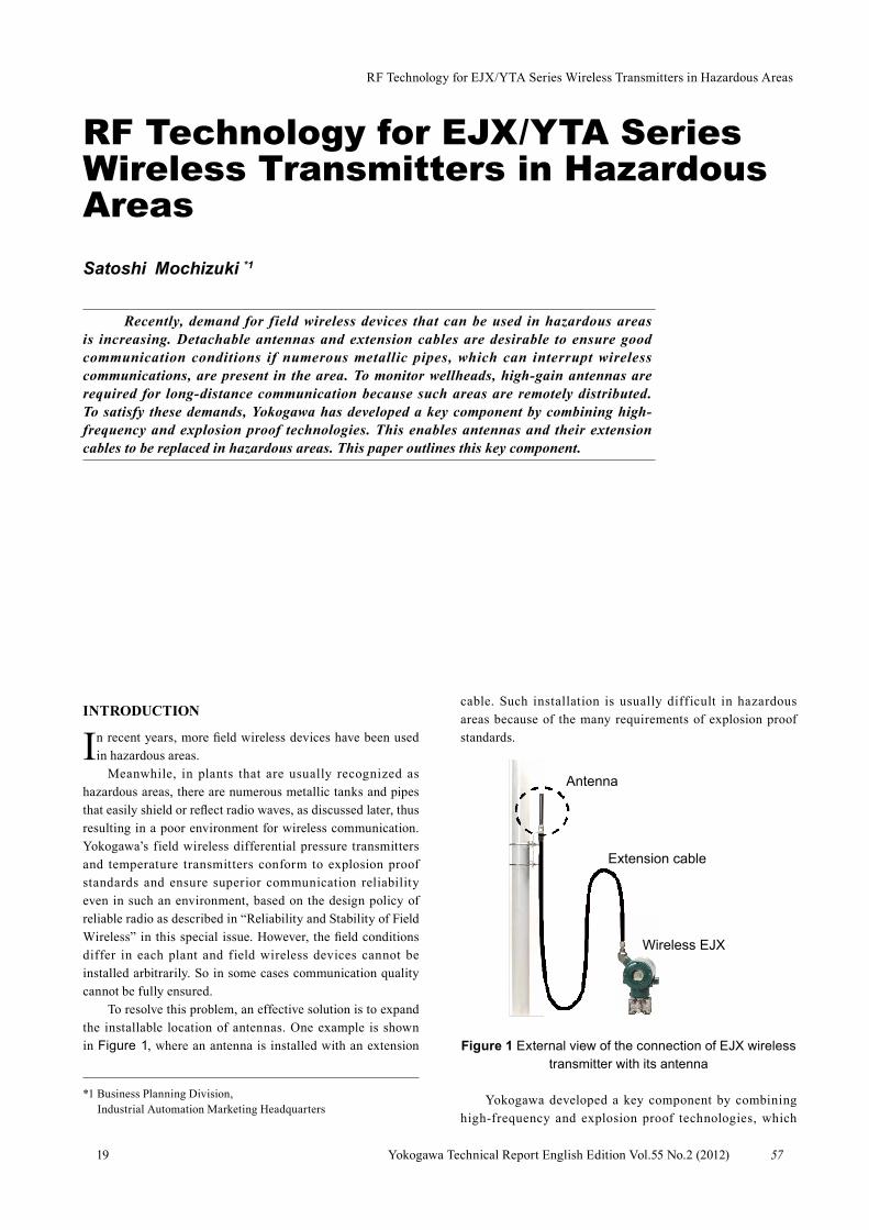
constant circuit which was actually developed. The substrate is inexpensive glass epoxy (FR-4) and its layer composition is designed so that it can be manufactured through usual processes.
Figure 3 Equivalent circuit
Figure 4 Designed Distributed constant circuit
Main Features of the CircuitMain features of the distributed constant circuit for
remote antennas are as follows. The RF filter function is included to widely suppress exogenous high-frequency noises out of the communication band;
Signal GND and frame GND are completely separated; A short stub structure is used to keep the DC potential of the single line the same as that of the frame GND in normal operation;
Suppressing in-band loss without using discrete parts lowers temperature dependence, extends communication distance, and stabilizes communication;
GND separation technologies enable the use of general-purpose antennas, coaxial extension cables, and coaxial arresters;
A distributed constant circuit incurs no cost for discrete parts;
Minimizing the effects caused by load changes facilitates application to other models.
Control of High Frequency and Magnetic Field Characteristics
Figures 5 to 7 show the high frequency characteristics of the distributed constant circuit shown in Figure 4. Figure 8 shows a conceptual diagram of magnetic field control to achieve highly efficient power transmission.
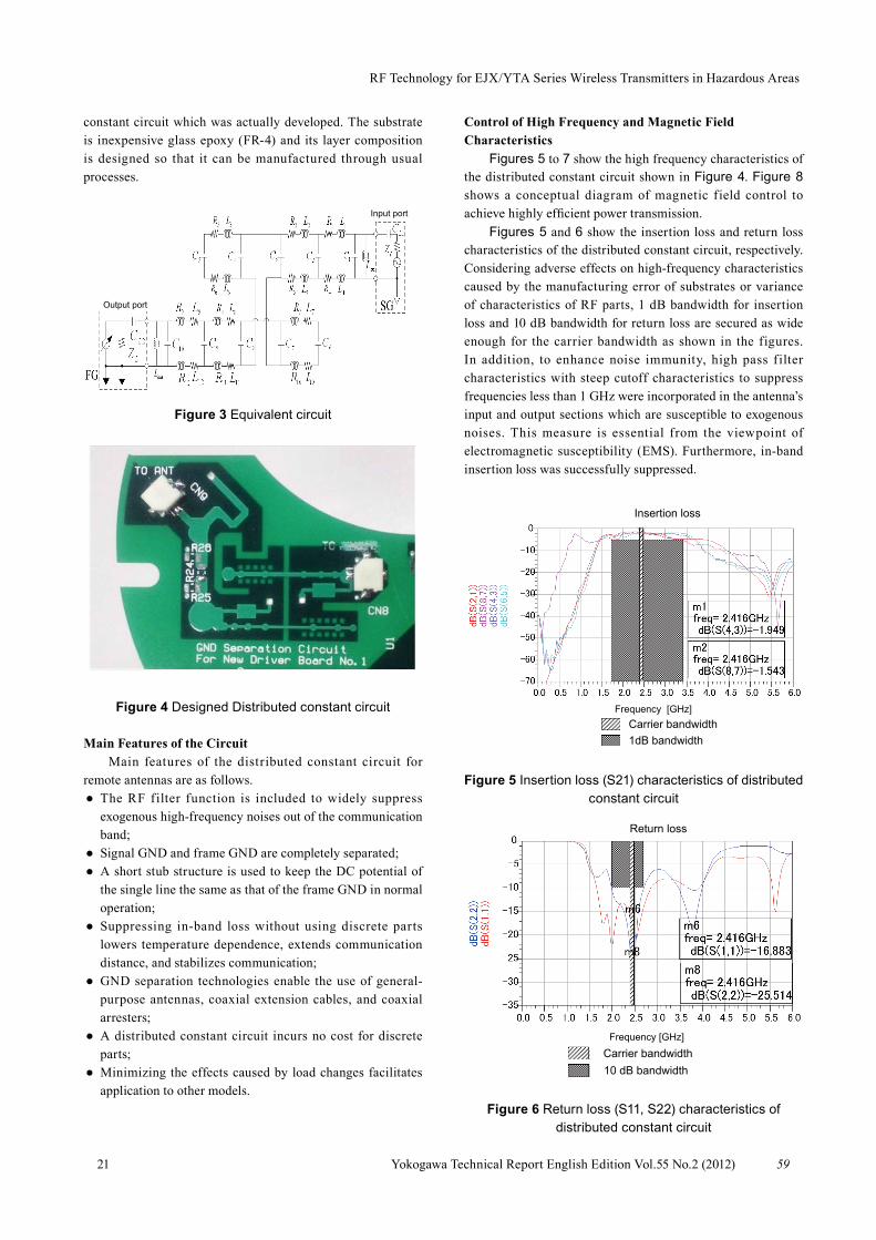
Figures 5 and 6 show the insertion loss and return loss characteristics of the distributed constant circuit, respectively. Considering adverse effects on high-frequency characteristics caused by the manufacturing error of substrates or variance of characteristics of RF parts, 1 dB bandwidth for insertion loss and 10 dB bandwidth for return loss are secured as wide enough for the carrier bandwidth as shown in the figures. In addition, to enhance noise immunity, high pass filter characteristics with steep cutoff characteristics to suppress frequencies less than 1 GHz were incorporated in the antenna’s input and output sections which are susceptible to exogenous noises. This measure is essential from the viewpoint of electromagnetic susceptibility (EMS). Furthermore, in-band insertion loss was successfully suppressed.
Figure 5 Insertion loss (S21) characteristics of distributed constant circuit
Figure 6 Return loss (S11, S22) characteristics of distributed constant circuit
Input port
Output port
Insertion loss
1dB bandwidthCarrier bandwidth
Frequency [GHz]
Return loss
Frequency [GHz]
Carrier bandwidth10 dB bandwidth
21 59
RF Technology for EJX/YTA Series Wireless Transmitters in Hazardous Areas
Yokogawa Technical Report English Edition Vol.55 No.2 (2012)
Figure 7 Input and output impedance characteristics
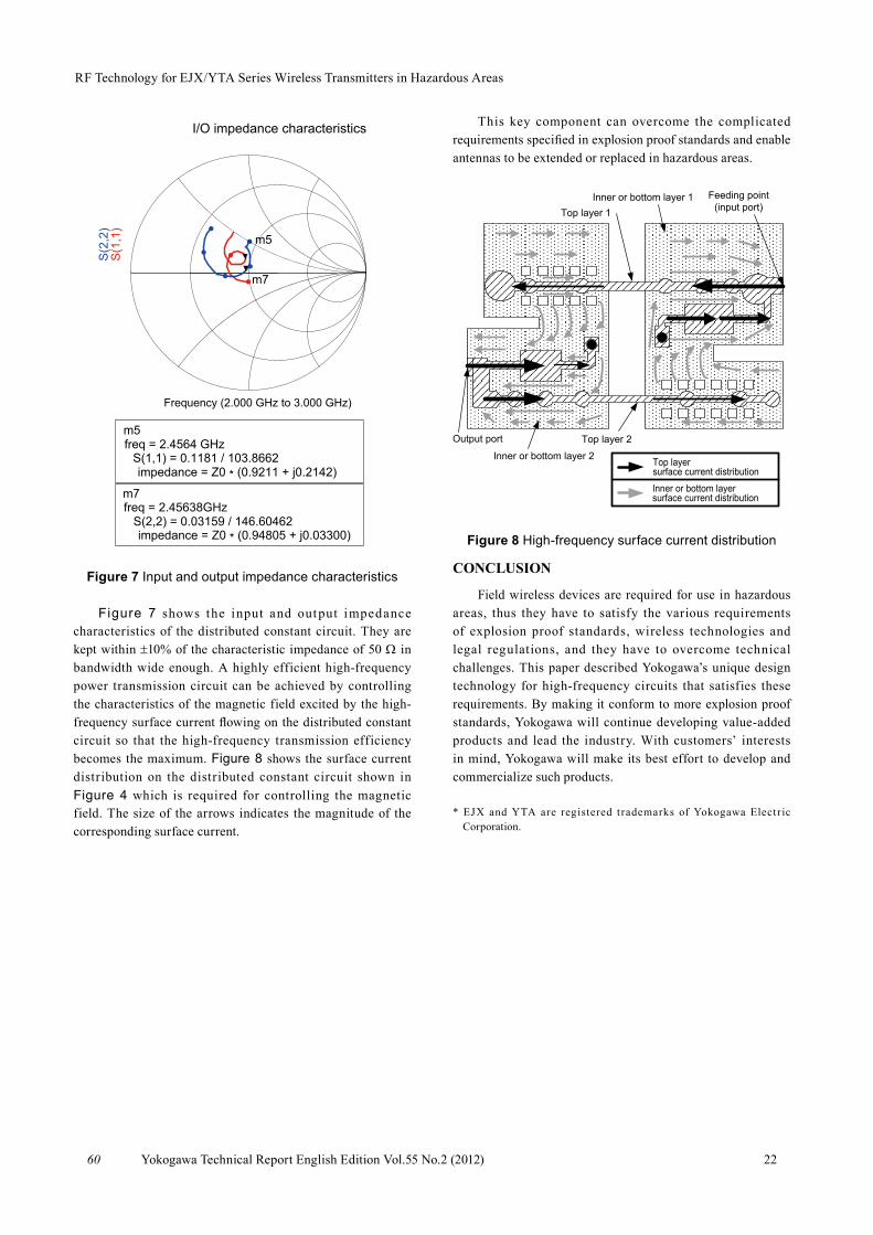
Figure 7 shows the input and output impedance characteristics of the distributed constant circuit. They are kept within ±10% of the characteristic impedance of 50 Ω in bandwidth wide enough. A highly efficient high-frequency power transmission circuit can be achieved by controlling the characteristics of the magnetic field excited by the high-frequency surface current flowing on the distributed constant circuit so that the high-frequency transmission efficiency becomes the maximum. Figure 8 shows the surface current distribution on the distributed constant circuit shown in Figure 4 which is required for controlling the magnetic field. The size of the arrows indicates the magnitude of the corresponding surface current.
This key component can overcome the complicated requirements specified in explosion proof standards and enable antennas to be extended or replaced in hazardous areas.
Figure 8 High-frequency surface current distribution
CONCLUSION
Field wireless devices are required for use in hazardous areas, thus they have to satisfy the various requirements of explosion proof standards, wireless technologies and legal regulations, and they have to overcome technical challenges. This paper described Yokogawa’s unique design technology for high-frequency circuits that satisfies these requirements. By making it conform to more explosion proof standards, Yokogawa will continue developing value-added products and lead the industry. With customers’ interests in mind, Yokogawa will make its best effort to develop and commercialize such products.
* EJX and YTA are registered t rademarks of Yokogawa Electr ic Corporation.
freq = 2.4564 GHzS(1,1) = 0.1181 / 103.8662impedance = Z0 * (0.9211 + j0.2142)
m7freq = 2.45638GHz
S(2,2) = 0.03159 / 146.60462impedance = Z0 * (0.94805 + j0.03300)
S(1
,1)
S(2
,2)
m5
m5
m7
Frequency (2.000 GHz to 3.000 GHz)
I/O impedance characteristics
Feeding point(input port)
Inner or bottom layer 1
Top layer 2
Top layer 1
Inner or bottom layer 2
Output port
Top layersurface current distribution
Inner or bottom layersurface current distribution
2260


![User’s Manual YTA Series Temperature Transmitters ...cdn2.us.yokogawa.com/IM01C50B01-01E.pdf · User’s Manual YTA Series Temperature Transmitters (Hardware) [Style: S3] IM 01C50B01-01E](https://img.pdfslide.net/doc/110x75/5a79fe887f8b9adf228c43aa/users-manual-yta-series-temperature-transmitters-cdn2us-s-manual-yta-series.jpg)
![User’s Manual EJX and EJA-E Series Differential Pressure ... · [EJX series Communication Manual] Models Document No. Style DPharp HART 5/HART 7 Communication Type IM 01C25T01-06EN](https://img.pdfslide.net/doc/110x75/5eda7023b3745412b5715724/useras-manual-ejx-and-eja-e-series-differential-pressure-ejx-series-communication.jpg)