Embed Size (px)
Citation preview

RF Wireless Spectrum Update

Spectrum Repacking
Here We Go Again:
The FCC is reallocating 600 MHz

Frequencies for Wireless Mics
30 - 45 MHz (8-m HF)
174 - 250 MHz (VHF)
450 - 960 MHz (UHF)
2400 - 2485 MHz (ISM)IndustrialScientificMedical
Antenna length ;
RF-interference from (electric)
appliances
Good wave propagation; TV-transmitters;
RF-distortions from digital equipment
wide frequency range
good wave propagation
poor wave propagation ;
no exclusive frequencies
(license free devices);
interference from microwave-ovens

UHF TV frequencies
TV Transmitter Wireless microphones
Yesterday:
Analog TV only
470 MHz 806 MHzCH14 CH69
2009
Digital Dividend
New Services
UHF TV frequencies 2009
Now:
Full Digital Scenario
DTV Transmitter
Transition:
Analog & DTV
DTV Transmitter

• “White Space” channels 2 – 51 are open to unlicensed
devices:
– Rural broadband internet
– Metropolitan broadband internet
– Multimedia services
– Home networking systems
– Consumer electronics: tablets, computers, media servers
and cell phones w/ advanced features
– Future products
White Space Devices (WSD) aka TV Band Devices (TVBD)
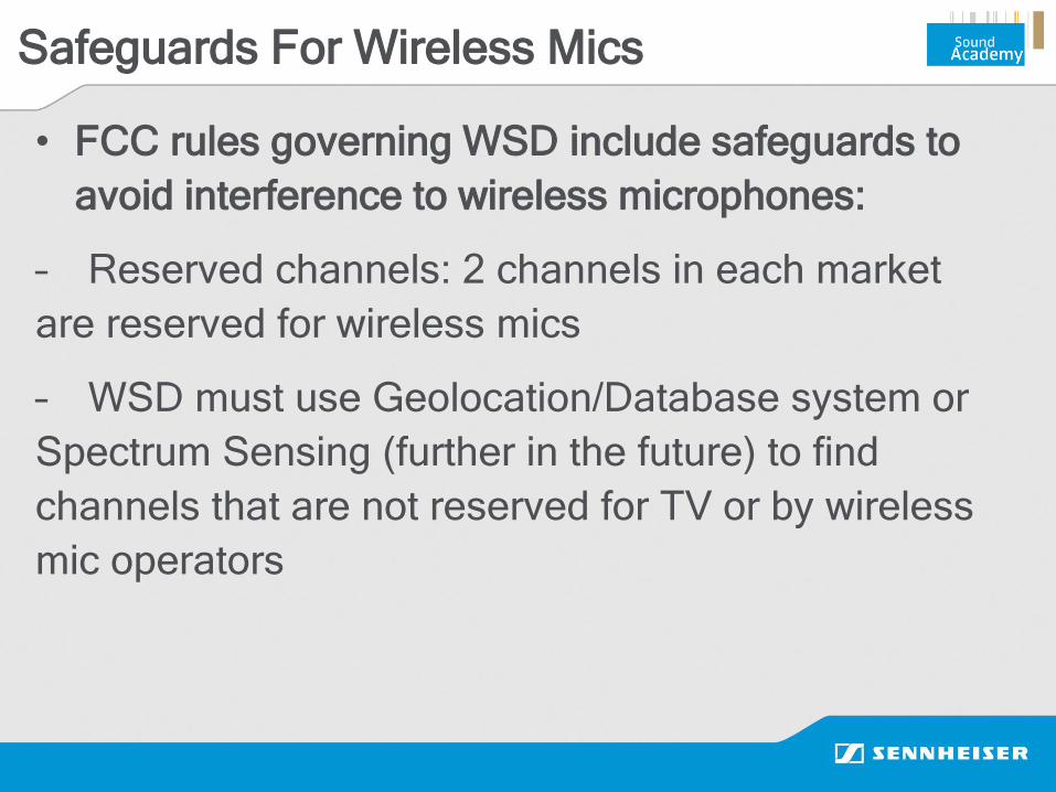
Safeguards For Wireless Mics
• FCC rules governing WSD include safeguards to
avoid interference to wireless microphones:
– Reserved channels: 2 channels in each market
are reserved for wireless mics
– WSD must use Geolocation/Database system or
Spectrum Sensing (further in the future) to find
channels that are not reserved for TV or by wireless
mic operators
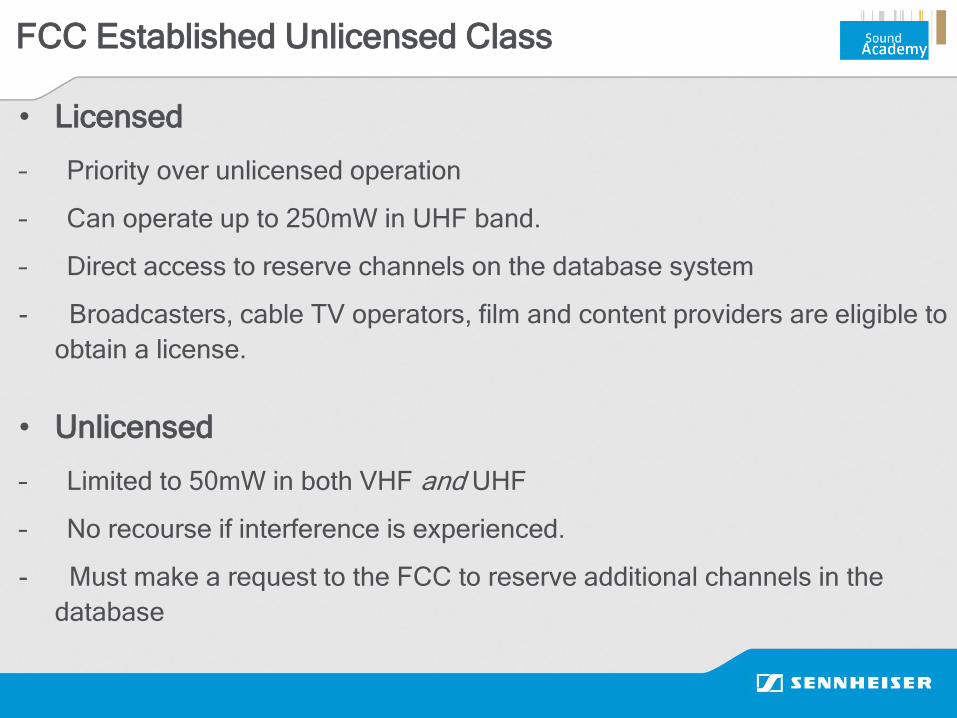
FCC Established Unlicensed Class
• Licensed
– Priority over unlicensed operation
– Can operate up to 250mW in UHF band.
– Direct access to reserve channels on the database system
- Broadcasters, cable TV operators, film and content providers are eligible to
obtain a license.
• Unlicensed
– Limited to 50mW in both VHF and UHF
– No recourse if interference is experienced.
- Must make a request to the FCC to reserve additional channels in the
database

Database System
Licensed mic operators have direct access to reserve additional channels

Database System
Licensed mic operators have direct access to reserve additional channels

UHF TV frequencies
TV Transmitter Wireless microphones
~20 years ago:
Analog TV only
470 MHz 806 MHzCH14 CH69
2009
Digital Dividend
New Services
UHF TV frequencies 2009
Now:
Full Digital Scenario
DTV Transmitter
Transition:
Analog & DTV
DTV Transmitter
Broadband + 2018?
Digital Dividend
New Services
UHF TV frequencies 2018?
Future:
More Broadband services
DTV Transmitter
New Incentive
Auction
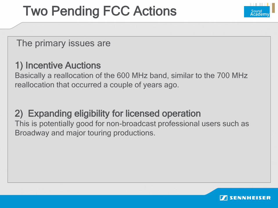
Two Pending FCC Actions
The primary issues are
1) Incentive AuctionsBasically a reallocation of the 600 MHz band, similar to the 700 MHz
reallocation that occurred a couple of years ago.
2) Expanding eligibility for licensed operationThis is potentially good for non-broadcast professional users such as
Broadway and major touring productions.
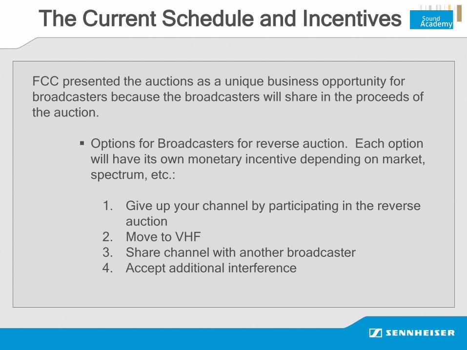
The Current Schedule and Incentives
FCC presented the auctions as a unique business opportunity for
broadcasters because the broadcasters will share in the proceeds of
the auction.
Options for Broadcasters for reverse auction. Each option
will have its own monetary incentive depending on market,
spectrum, etc.:
1. Give up your channel by participating in the reverse
auction
2. Move to VHF
3. Share channel with another broadcaster
4. Accept additional interference

The Current Schedule and Incentives
Order and Report will be finalized in 2014.
Bidding and repacking auction scheduled for the middle of 2015,
afterwards payments and licensing will take place.
The Current Schedule and Incentives
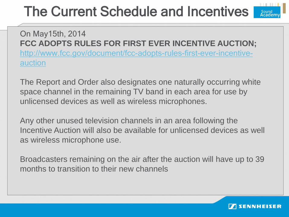
On May15th, 2014
FCC ADOPTS RULES FOR FIRST EVER INCENTIVE AUCTION;
http://www.fcc.gov/document/fcc-adopts-rules-first-ever-incentive-
auction
The Report and Order also designates one naturally occurring white
space channel in the remaining TV band in each area for use by
unlicensed devices as well as wireless microphones.
Any other unused television channels in an area following the
Incentive Auction will also be available for unlicensed devices as well
as wireless microphone use.
Broadcasters remaining on the air after the auction will have up to 39
months to transition to their new channels
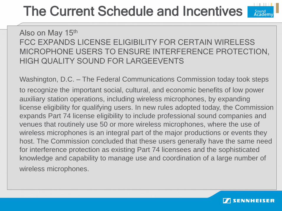
The Current Schedule and Incentives
Also on May 15th
FCC EXPANDS LICENSE ELIGIBILITY FOR CERTAIN WIRELESS
MICROPHONE USERS TO ENSURE INTERFERENCE PROTECTION,
HIGH QUALITY SOUND FOR LARGEEVENTS
Washington, D.C. – The Federal Communications Commission today took steps
to recognize the important social, cultural, and economic benefits of low power
auxiliary station operations, including wireless microphones, by expanding
license eligibility for qualifying users. In new rules adopted today, the Commission
expands Part 74 license eligibility to include professional sound companies and
venues that routinely use 50 or more wireless microphones, where the use of
wireless microphones is an integral part of the major productions or events they
host. The Commission concluded that these users generally have the same need
for interference protection as existing Part 74 licensees and the sophisticated
knowledge and capability to manage use and coordination of a large number of
wireless microphones.

What Is Sennheiser Doing?
Communicating
&
Innovating

What can you do to help?
Help support Sennheisers proposal
HOW CAN I SUPPORT THE PETITION FOR COMPENSATION?
It is easy. Write a brief letter of support that includes these three basic
elements:
1) reference docket number 12-268,
2) state who you are (e.g. I am a performing artist that uses wireless
mics and monitors)
3) state that you agree with Sennheiser's proposal for auction winners to
compensate wireless mic owners for any equipment that they will not be
able to use after spectrum repacking.
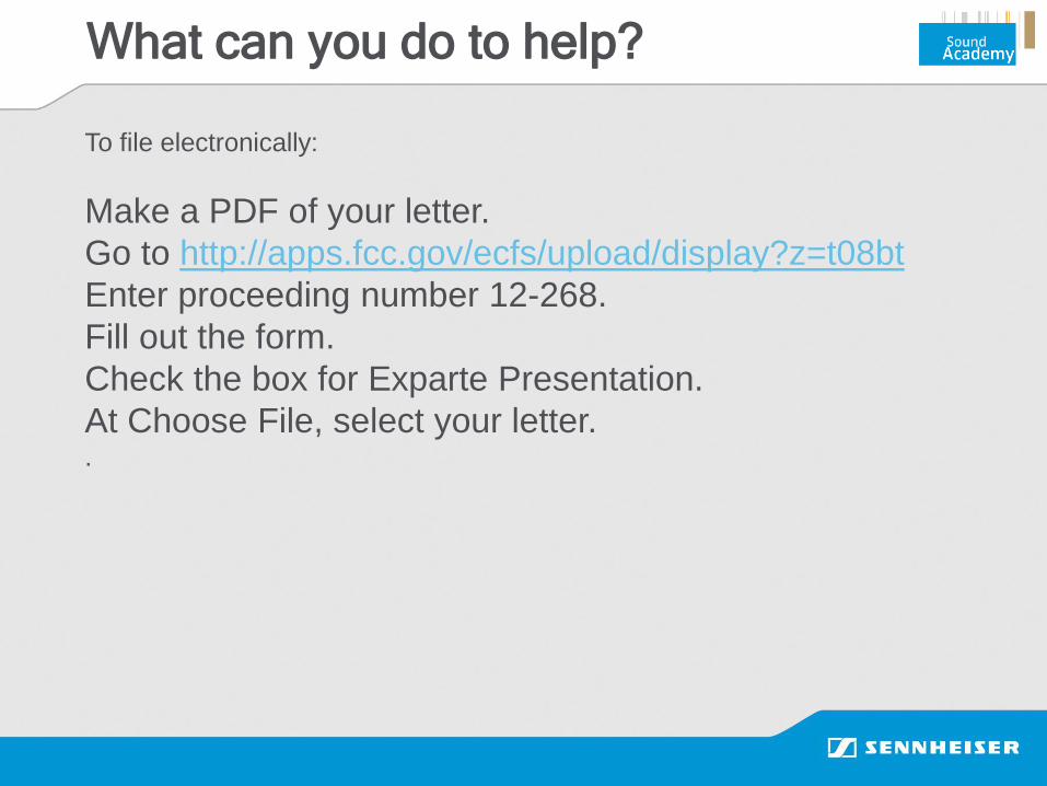
What can you do to help?
To file electronically:
Make a PDF of your letter.
Go to http://apps.fcc.gov/ecfs/upload/display?z=t08bt
Enter proceeding number 12-268.
Fill out the form.
Check the box for Exparte Presentation.
At Choose File, select your letter. .

Digital Wireless Systems

Digital
Why the push for digital?
The promise and potential advantages of converting the natively analog
audio signal to digital data prior to transmission can be summarized to:
• Better and more consistent audio quality.
• Transmission of digital data allows for increased information capacity
within comparable bandwidth (= better spectrum efficiency).
• Transmission security (encryption).
• Superior immunity to interference.
• Additional features through software/firmware updates.
The main driving force remains BEST POSSIBLE AUDIO QUALITY !
(S/N, frequency response, immunity to interference)
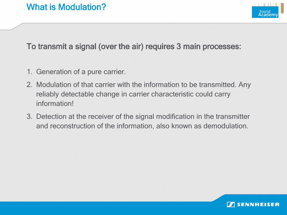
What is Modulation?
To transmit a signal (over the air) requires 3 main processes:
1. Generation of a pure carrier.
2. Modulation of that carrier with the information to be transmitted. Any
reliably detectable change in carrier characteristic could carry
information!
3. Detection at the receiver of the signal modification in the transmitter
and reconstruction of the information, also known as demodulation.
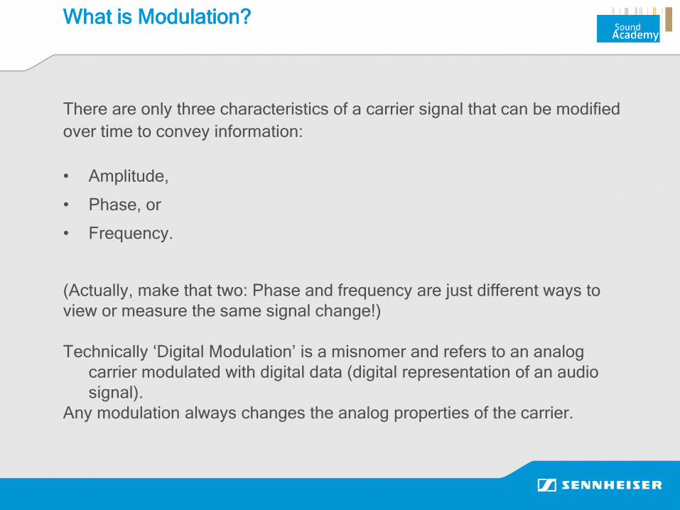
What is Modulation?
There are only three characteristics of a carrier signal that can be modified
over time to convey information:
• Amplitude,
• Phase, or
• Frequency.
(Actually, make that two: Phase and frequency are just different ways to
view or measure the same signal change!)
Technically ‘Digital Modulation’ is a misnomer and refers to an analog
carrier modulated with digital data (digital representation of an audio
signal).
Any modulation always changes the analog properties of the carrier.
Analog (Scalar) Modulation
Amplitude Modulation (AM): In AM the frequency of the carrier is kept
constant and its amplitude is changed in proportion to the instantaneous
amplitude of the modulating message signal.
• min. required BW = 2*AFmax
• max. S/N ≈ 30 dBA (affected by fading)
• AF response limited by occupied BW
Frequency Modulation (FM): In FM the amplitude of the modulated carrier
is kept constant, while the frequency is varied in proportion to the
instantaneous amplitude of the modulating message signal.
• min. required BW = 2*(Df + AFmax)
• max. S/N ≈ 50 dBA (for typ. Df = ±50 kHz w.o. AF processing - ≥100 dB
w. dyn. processing and RF signal strength at Rx > -80 dBm)
• AF response dependent on BW

Analog Modulation

Digital Modulation
• With analog modulation systems, the information signal is analog.
• With digital modulation, the information signal is digital.
• Either system uses analog carriers!
Digital Audio Representation
In order to achieve superior audio quality we strive for a frequency response
up to 20 kHz and a dynamic range (S/N) of >108 dB.
• This minimum requirement can be achieved with an A-to-D conversion of
18 bits with a sampling rate of 44.1 kHz, resulting in a bit rate of
793.4 kBit/sec.
• Technically possible today is an A-to-D conversion with 24 bit at a
sampling rate of 96 kHz, resulting in a bit rate of 2.304 MBit/sec.
• To facilitate reliable transmission additional data is required for framing
and coding, expanding the data rate typically by a factor of ≈ 1.5 and
resulting in gross bit rates of 1,2 MBit/sec and 3.45 MBit/sec respectively.

Digitized Audio
24Bit, 96kHz18Bit, 44.1kHz

The Challenge of Digital Audio Transmission
Regulations for wireless microphones operating in the UHF frequency
range limit the maximum occupied BW to 200 kHz!
At first glance attempting to transmit high quality digital audio (data rate of
1.2 MBit/s) through this narrow BW (200 kHz) looks like shoveling 1.2 tons
of ……… into a 200 pound bag…
One possible option could be some processing of the digital data to result in
significant data reduction or compression. Any such data processing may
affect the ultimate audio quality and possibly introduce additional
processing delays (‘latency’).

One possible solution to meet the challenge of transmitting uncompressed
high quality audio is through Quadrature Amplitude Modulation (QAM):
The advantage of QAM is that it is a higher order form of modulation and
as a result it is able to carry more bits of information per symbol. By
selecting a higher order format of QAM, the data rate of a link can be
increased.
The table below gives a summary of the bit rates of different forms of
QAM and PSK( Phase-Shift Keying).
The Challenge of Digital Audio Transmission

• Modulation type determines number of bits per symbol
– BPSK 1 bit/symbol (Binary Phase Shift-Keying)
– DBPSK 1 bit/symbol (Differential Binary Phase Shift-Keying)
– QPSK 2 bit/symbol (Quadrature Phase Shift-Keying)
– DQPSK 2 bit/symbol (Differential Quadrature Phase Shift-Keying)
– 8PSK 3 bit/symbol
– 16QAM 4 bit/symbol (Quadrature Amplitude Modulation)
– 64QAM 6 bit/symbol
– 256QAM 8 bit/symbol
• For a fixed symbol rate, having more bits will provide a faster transfer rate
Simple modulation schemes like FSK, PSK, ASK offer only a fraction of
the needed data rate within the permissible bandwidth (typ. ≤ 150 - 200
kbit/s).
The Challenge of Digital Audio Transmission
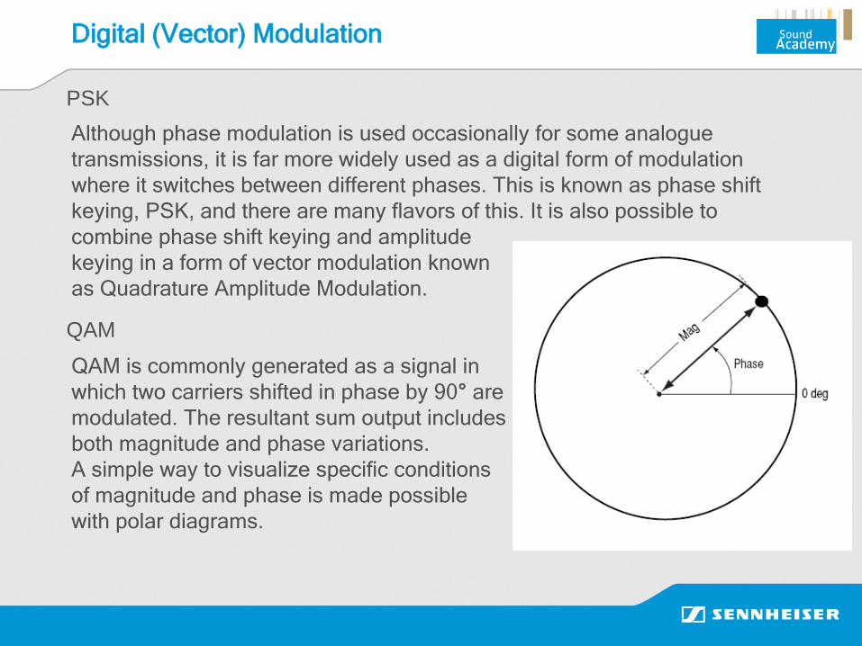
Digital (Vector) Modulation
Although phase modulation is used occasionally for some analogue
transmissions, it is far more widely used as a digital form of modulation
where it switches between different phases. This is known as phase shift
keying, PSK, and there are many flavors of this. It is also possible to
combine phase shift keying and amplitude
keying in a form of vector modulation known
as Quadrature Amplitude Modulation.
QAM is commonly generated as a signal in
which two carriers shifted in phase by 90° are
modulated. The resultant sum output includes
both magnitude and phase variations.
A simple way to visualize specific conditions
of magnitude and phase is made possible
with polar diagrams.
PSK
QAM

Constellation Diagrams for QAM
Constellation diagrams show the different positions for the end points of the
vectors from corresponding polar diagrams. Shown here are representations
for different forms of Quadrature Amplitude Modulation (QAM). As the order
of the modulation increases, so does the number of points (CP) on the QAM
constellation diagrams.
4 bits/symbol (24 CPs) 5 bits/symbol (25 CPs) 6 bits/symbol (26 CPs)

-4 -3 -2 -1 0 1 2 3 4
-4
-3
-2
-1
0
1
2
3
4
Quadra
ture
In-Phase
Scatter plot
i
jq
10101110
1011
0110
11110111
0010
0011
1101 100101010001
0000 0100 1100 1000
16 QAM
Discrete Amplitude and Phase Constellation
Points (CP) are defined to represent a
certain Bit(-sequence
Number of CPs/Symbols per Second
is limited by given RF Bandwidth
The modulated RF Carrier (Vector)
goes continuously from one to the
other Constellation Point depending
on Bit sequence to be sent

The Challenge of Digital Audio Transmission
Higher order modulation rates are able to offer much faster data rates
and higher levels of spectral efficiency for the radio communications system,
this comes at a price. The higher order modulation schemes are considerably
less resilient to noise and interference. In consequence this requires:
• higher carrier-to-noise and carrier-to-interference ratio at the receiver
(CNR/CIR) resulting in the need for more transmit power;
• very accurate modulation with effective carrier and sideband suppression;
• extremely high linearity in all stages of the transmitter and receiver chains;
• great efforts to be applied to carrier and symbol recovery.
What does this mean for system design?
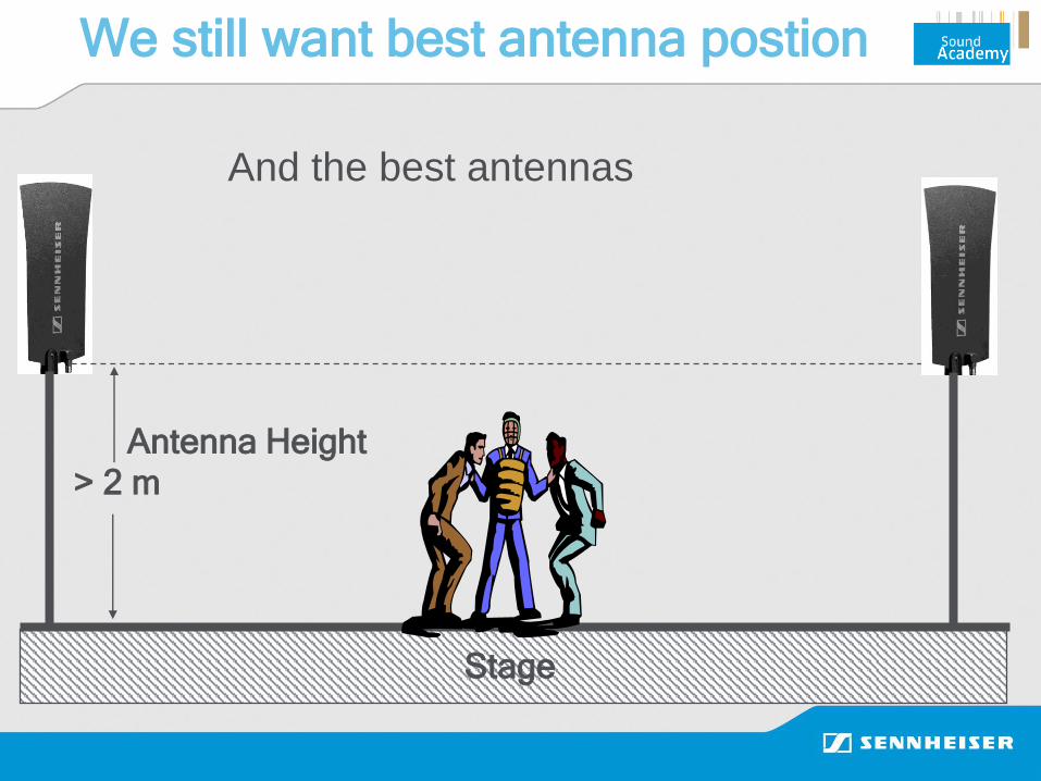
We still want best antenna postion
Stage
> 2 m
Antenna Height
And the best antennas
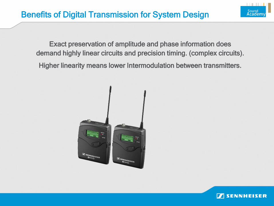
Exact preservation of amplitude and phase information does
demand highly linear circuits and precision timing. (complex circuits).
Higher linearity means lower Intermodulation between transmitters.
Benefits of Digital Transmission for System Design

F1 F2
800 801
IM 3 IM 3
802
Intermodulation
2F1 - F2
799 F (MHz)803798
IM 5 IM 5
Virtual TX
Virtual TX
F3 F4

Benefits of Digital Transmission for System Design
Typical Analog Transmitter Intermodulation

Benefits of Digital Transmission for System Design
Digital Transmitters Have the Possibility of No Intermodulation

10uV
500uV
1000uV
Squelch threshold
Analog systems require audio mute controlled
by RF signal strength
Noise floor
Wanted signal
min. 100uV
Benefits of Digital Transmission for System Design
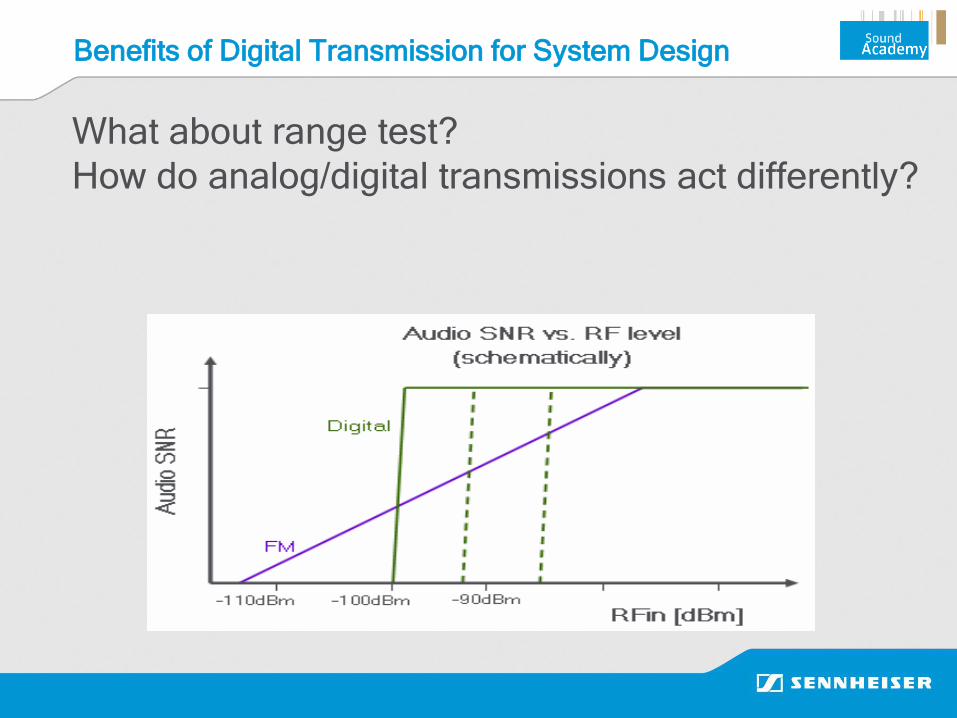
Benefits of Digital Transmission for System Design
What about range test?
How do analog/digital transmissions act differently?

We still want best low loss cable
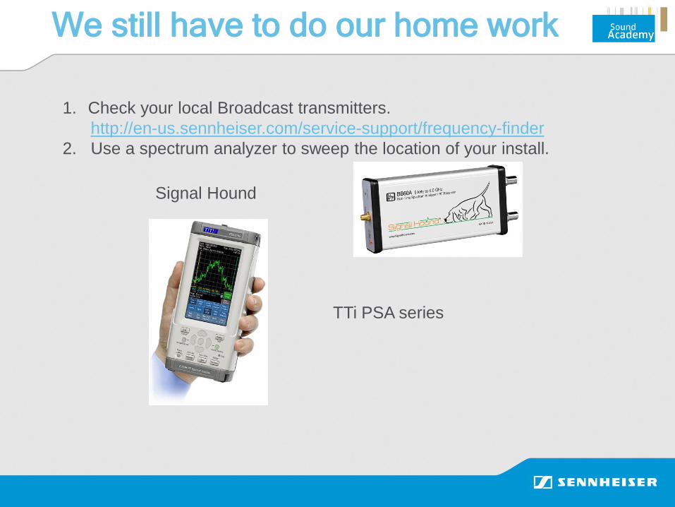
We still have to do our home work
1. Check your local Broadcast transmitters.
http://en-us.sennheiser.com/service-support/frequency-finder
2. Use a spectrum analyzer to sweep the location of your install.
Signal Hound
TTi PSA series

Thank You!