Embed Size (px)
Citation preview
RF1276 Long Distance Transceiver module V2.0
- 1 - 2014-1-12
1. GeneralRF1276 series is a low cost, ultra-low power, high performance transparent two way semi-duplex LoRa
modulation transceiver with operation at 169/315/433/868/915 Mhz. It integrates with high speed MCU from
ST and high performance RF IC SX1276. Adopting high efficiency forward error correction with
interleaving encoding (FEC) technology, it makes anti-interference ability and reception sensitivity greatly
improved. That guarantees good performance in the harsh environment such as some industrial application.
The FEC technique is advanced and unique in radio data communication field.
RF1276 has the UART/RS232/RS485 interface, that make it is easy to implement wireless data
transmission. It is flexible for users to set the baud rate, frequency, output power, air data rate etc parameters.
It can transmit transparent data with large data buffer and also can provide over 32 channels. The compact
size makes it an ideal option for radio data communication application.
RF1276 Long Distance Transceiver module V2.0
- 2 - 2014-1-12
2. Features 5000 meters of communication distance(300bps)
Output power: Max100mW (20dBm) (127 levels adjustable)
Air data rate: 300 - 19200bps, can be configured through RF tool
UART data rate: 1200 - 57600bps, can be configured through RF tool
Frequency: 169MHz,315MHz,405MHz - 440MHz, 868MHz or 915MHz
Working Current: 90mA(TX), 19.2mA(RX), 2.2mA(idle), 220uA(Sleeping)
More than 32 channels
parity of series COM: 8E1/8N1/8O1
LoRa modulation
Receive sensitivity: -148dBm(@300bps)
UART/TTL, RS232, RS485
Exceed 256 bytes data buffer
Supply Voltage: 4.5 – 5.5V (the ripple less than ±100mV )
Simply tool for configuration
250KHz Channel spacing
Dimension: 44.5mm x 23.6mm x 7.0mm
3. Application: Automated Meter Reading (AMR)
Remote control, remote measurement system
Access control
Data collection
Identification system
IT household appliance
Baby monitoring system
RF1276 Long Distance Transceiver module V2.0
- 3 - 2014-1-12
4. Maximum specification
Symbol Parameter Min Max Units
VCC Supply Voltage 4.5 5.5 V
TOT Operation Temperature -30 85 ℃
HOH Operation Humidity 10% 90%
TST Storage Temperature -55 125 °C
5. Pin Out: RF1276 module has 5 pins. Refers to the Table 1:
RF1276
Pin NO. Pin Name Description
1 VCC Power supply DC 4.5V-6.5V
2 GND Grounding of Power Supply
3 RXD Serial input, 485+/485A
4 TXD Serial output, 485-/485B
5 AUX Data in/out indication
Table 1: Pin definition
6. Working mode
a. Standard mode
Standard mode is also called transparent mode in which the module receives from or sends data to the host
through serial port (RS232 or RS485) at preset data format and users don’t need to care about the proce ss of
data inside the module. The AUX pin of RF1276 will give indication about the data IN/OUT of serial port
2ms in advance in order to wake up the host.
RF1276 Long Distance Transceiver module V2.0
- 4 - 2014-1-12
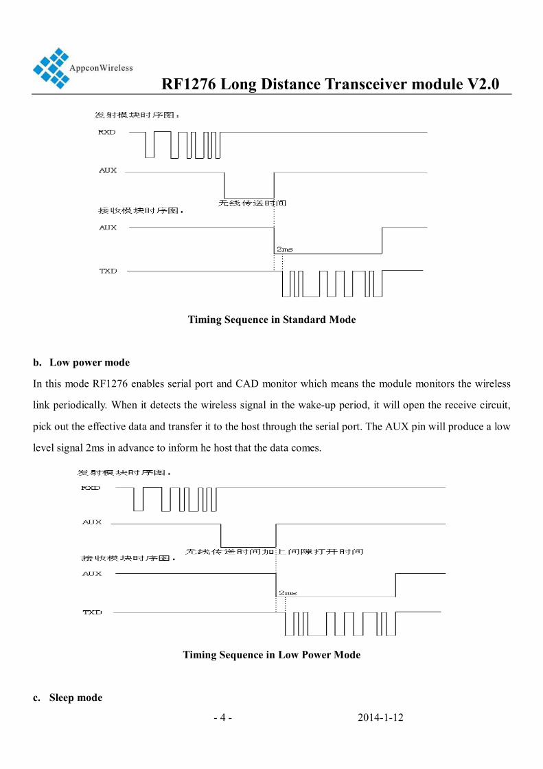
Timing Sequence in Standard Mode
b. Low power mode
In this mode RF1276 enables serial port and CAD monitor which means the module monitors the wireless
link periodically. When it detects the wireless signal in the wake-up period, it will open the receive circuit,
pick out the effective data and transfer it to the host through the serial port. The AUX pin will produce a low
level signal 2ms in advance to inform he host that the data comes.
Timing Sequence in Low Power Mode
c. Sleep mode
RF1276 Long Distance Transceiver module V2.0
- 5 - 2014-1-12
In this mode most functions of the modules are disabled so if two modules are set to the Sleep Mode, they
can’t communicate with each other so one module must be in Low Power Mode. Comparing to Low Power
Mode, the modules in SLEEP MODE will not enable serial port and only keeps CAD monitor. When it
detects effective wireless signal, it will then enable the serial port. If there is no data In/Out in 1 seco nd, it
will close the serial port and continue the CAD monitor
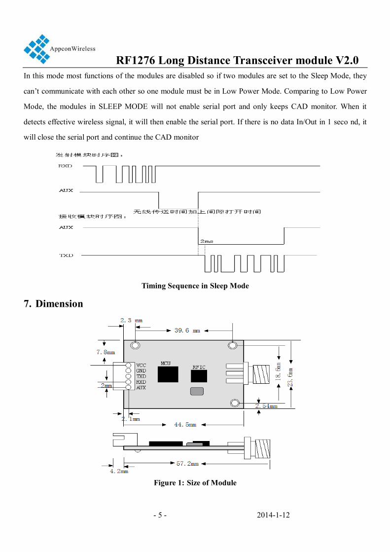
Timing Sequence in Sleep Mode
7. Dimension
Figure 1: Size of Module
RF1276 Long Distance Transceiver module V2.0
- 6 - 2014-1-12
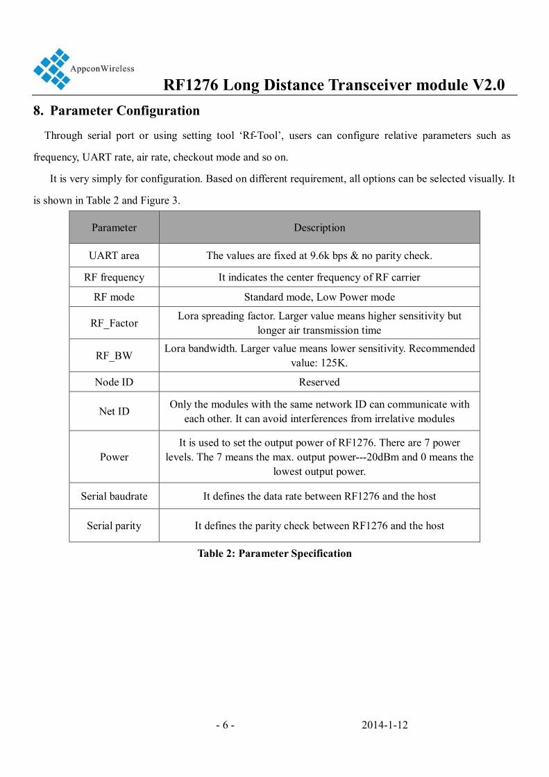
8. Parameter Configuration
Through serial port or using setting tool ‘Rf-Tool’, users can configure relative parameters such as
frequency, UART rate, air rate, checkout mode and so on.
It is very simply for configuration. Based on different requirement, all options can be selected visually. It
is shown in Table 2 and Figure 3.
Parameter Description
UART area The values are fixed at 9.6k bps & no parity check.
RF frequency It indicates the center frequency of RF carrier
RF mode Standard mode, Low Power mode
RF_Factor Lora spreading factor. Larger value means higher sensitivity but
longer air transmission time
RF_BW Lora bandwidth. Larger value means lower sensitivity. Recommended
value: 125K.
Node ID Reserved
Net ID Only the modules with the same network ID can communicate with each other. It can avoid interferences from irrelative modules
Power It is used to set the output power of RF1276. There are 7 power
levels. The 7 means the max. output power---20dBm and 0 means the lowest output power.
Serial baudrate It defines the data rate between RF1276 and the host
Serial parity It defines the parity check between RF1276 and the host
Table 2: Parameter Specification
RF1276 Long Distance Transceiver module V2.0
- 7 - 2014-1-12
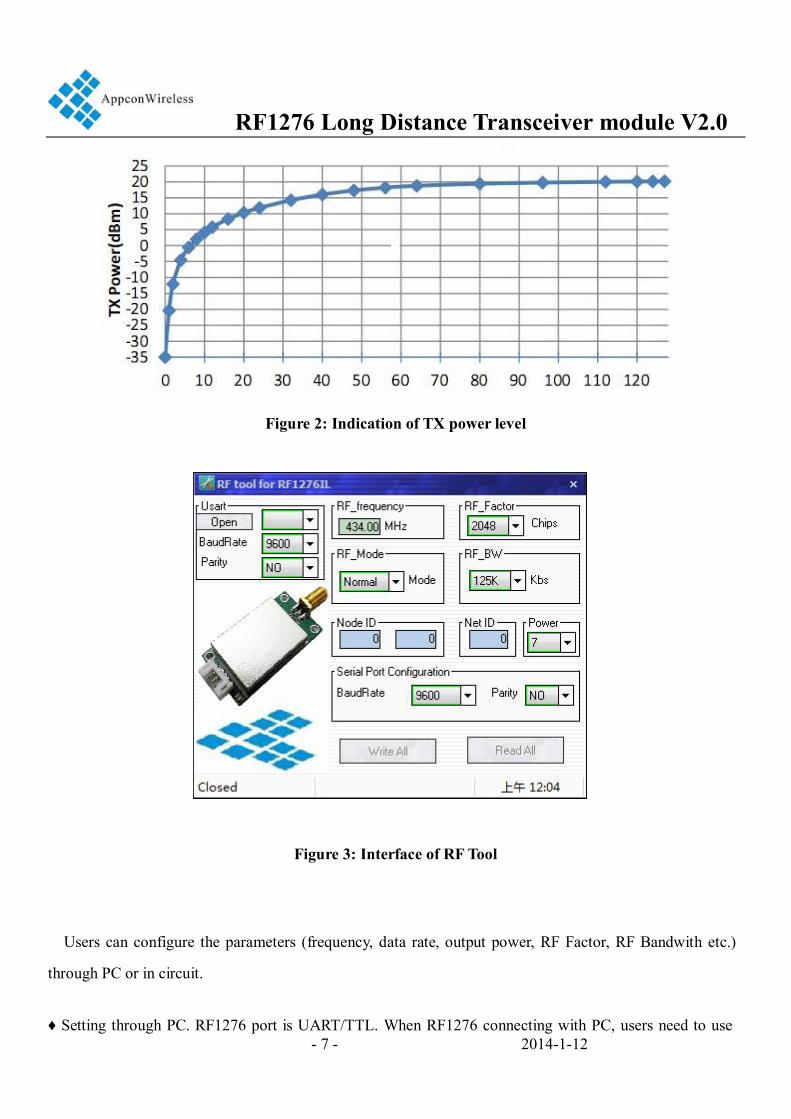
Figure 2: Indication of TX power level
Figure 3: Interface of RF Tool
Users can configure the parameters (frequency, data rate, output power, RF Factor, RF Bandwith etc.)
through PC or in circuit.
♦ Setting through PC. RF1276 port is UART/TTL. When RF1276 connecting with PC, users need to use
RF1276 Long Distance Transceiver module V2.0
- 8 - 2014-1-12
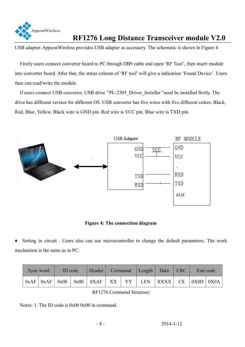
USB adapter. AppconWireless provides USB adapter as accessory. The schematic is shown in Figure 4
Firstly users connect converter board to PC through DB9 cable and open ‘RF Tool’, then insert module
into converter board. After that, the status column of ‘RF tool’ will give a indication ‘Found Device’. Users
then can read/write the module.
If users connect USB converter, USB drive ’’PL-2303_Driver_Installer’’need be installed firstly. The
drive has different version for different OS. USB converter has five wires with five different colors: Black,
Red, Blue, Yellow. Black wire is GND pin. Red wire is VCC pin. Blue wire is TXD pin.
Figure 4: The connection diagram
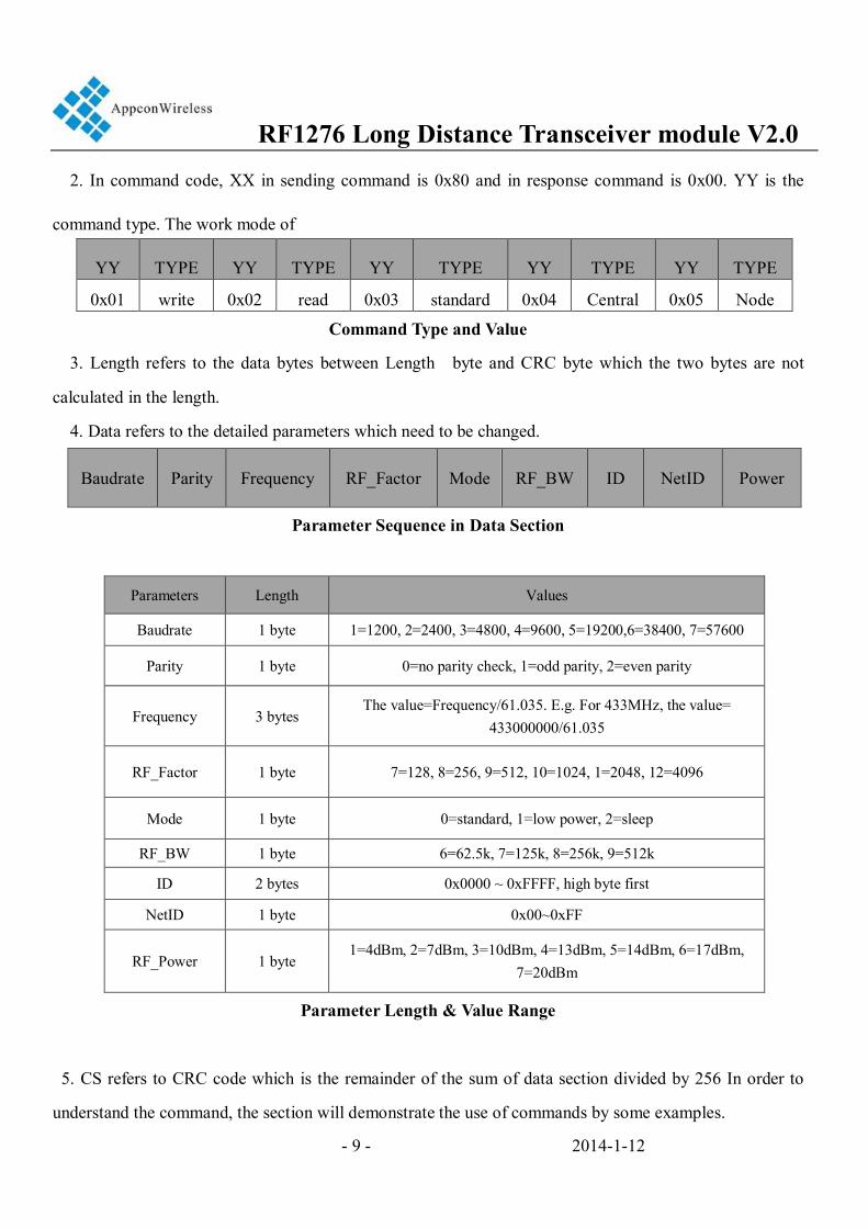
♦ Setting in circuit . Users also can use microcontroller to change the default parameters. The work
mechanism is the same as in PC.
Sync word ID code Header Command Length Data CRC End code
0xAF 0xAF 0x00 0x00 0XAF XX YY LEN XXXX CS 0X0D 0X0A
RF1276 Command Structure
Notes: 1. The ID code is 0x00 0x00 in command.
RF1276 Long Distance Transceiver module V2.0
- 9 - 2014-1-12
2. In command code, XX in sending command is 0x80 and in response command is 0x00. YY is the
command type. The work mode of
YY TYPE YY TYPE YY TYPE YY TYPE YY TYPE
0x01 write 0x02 read 0x03 standard 0x04 Central 0x05 Node
Command Type and Value
3. Length refers to the data bytes between Length byte and CRC byte which the two bytes are not
calculated in the length.
4. Data refers to the detailed parameters which need to be changed.
Baudrate Parity Frequency RF_Factor Mode RF_BW ID NetID Power
Parameter Sequence in Data Section
Parameters Length Values
Baudrate 1 byte 1=1200, 2=2400, 3=4800, 4=9600, 5=19200,6=38400, 7=57600
Parity 1 byte 0=no parity check, 1=odd parity, 2=even parity
Frequency 3 bytes The value=Frequency/61.035. E.g. For 433MHz, the value=
433000000/61.035
RF_Factor 1 byte 7=128, 8=256, 9=512, 10=1024, 1=2048, 12=4096
Mode 1 byte 0=standard, 1=low power, 2=sleep
RF_BW 1 byte 6=62.5k, 7=125k, 8=256k, 9=512k
ID 2 bytes 0x0000 ~ 0xFFFF, high byte first
NetID 1 byte 0x00~0xFF
RF_Power 1 byte 1=4dBm, 2=7dBm, 3=10dBm, 4=13dBm, 5=14dBm, 6=17dBm,
7=20dBm
Parameter Length & Value Range
5. CS refers to CRC code which is the remainder of the sum of data section divided by 256 In order to
understand the command, the section will demonstrate the use of commands by some examples.
RF1276 Long Distance Transceiver module V2.0
- 10 - 2014-1-12
Write Command Code: 0x01
Command: 0xAF, 0xAF, 0x00, 0x00, 0xAF, 0x80, 0x01, 0x0C, .... CS, 0x0D, 0x0A
Response.: 0xAF, 0xAF, 0x00, 0x00, 0xA F, 0x00, 0x01, 0x0C, .... CS, 0x0D, 0x0A
Read Command Code: 0x02
Command: 0xAF, 0xAF, 0x00, 0x00, 0xAF, 0x80, 0x02, 0x02,0x00,0x00,0x91, 0x0D, 0x0A
Response.: 0xAF, 0xAF, 0x00, 0x00, 0xAF, 0x00, 0x02, 0x02,0x00,0x00,0x91, 0x0D, 0x0A
Standard Mode Command Code: 0x03
Command: 0xAF, 0xAF, 0x00, 0x00, 0xAF, 0x80, 0x03, 0x02, 0x00, 0x00, 0x92, 0x0D, 0x0A
Response.: 0xAF, 0xAF, 0x00, 0x00, 0xAF, 0x00, 0x03, 0x02, 0x00, 0x00, 0x92, 0x0D, 0x0A
Central Mode Command Code: 0x04
Command: 0xAF, 0xAF, 0x00, 0x00, 0xAF, 0x80, 0x04, 0x02, 0x00, 0x00, 0x93, 0x0D, 0x0A
Response.: 0xAF, 0xAF, 0x00, 0x00, 0xAF, 0x00, 0x04, 0x02, 0x00, 0x00, 0x93, 0x0D, 0x0A
Node Mode Command Code: 0x05
Command: 0xAF, 0xAF, 0x00, 0x00, 0xAF, 0x80, 0x05, 0x02, 0x00, 0x00, 0x94, 0x0D, 0x0A
Response.: 0xAF, 0xAF, 0x00, 0x00, 0xAF, 0x00, 0x05, 0x02, 0x00, 0x00, 0x94, 0x0D, 0x0A
Please note that the working modes changed by the 0x03, 0x04 and 0x05 commands will not be written
into nonvolatile memory so the working mode will be restored to the former mode before change after
power-off. Users can use the WRITE command to change the working mode of module to standard mode
or low power mode but the sleep mode will be restored to standard mode after next power-on even if the
WRITE command is used.
RF1276 Long Distance Transceiver module V2.0
- 11 - 2014-1-12
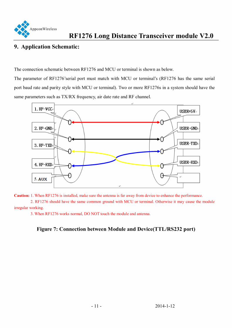
9. Application Schematic:
The connection schematic between RF1276 and MCU or terminal is shown as below.
The parameter of RF1276’serial port must match with MCU or terminal’s (RF1276 has the same serial
port baud rate and parity style with MCU or terminal). Two or more RF1276s in a system should have the
same parameters such as TX/RX frequency, air date rate and RF channel.
Caution: 1. When RF1276 is installed, make sure the antenna is far away from device to enhance the performance. 2. RF1276 should have the same common ground with MCU or terminal. Otherwise it may cause the module irregular working. 3. When RF1276 works normal, DO NOT touch the module and antenna.
Figure 7: Connection between Module and Device(TTL/RS232 port)
RF1276 Long Distance Transceiver module V2.0
- 12 - 2014-1-12
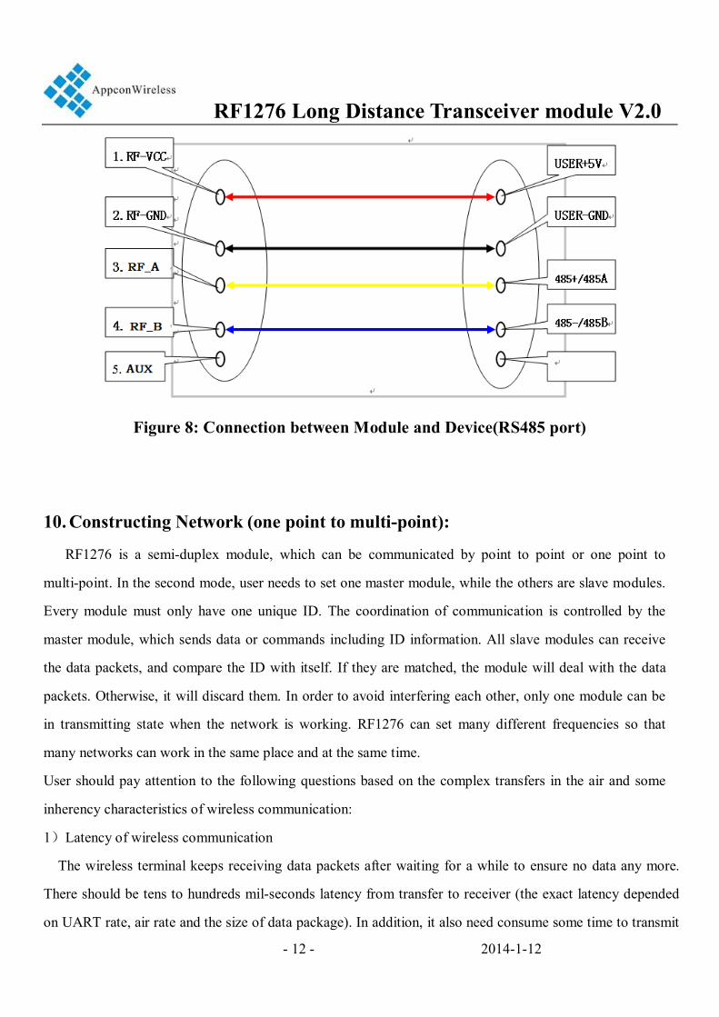
Figure 8: Connection between Module and Device(RS485 port)
10. Constructing Network (one point to multi-point):
RF1276 is a semi-duplex module, which can be communicated by point to point or one point to
multi-point. In the second mode, user needs to set one master module, while the others are slave modules.
Every module must only have one unique ID. The coordination of communication is controlled by the
master module, which sends data or commands including ID information. All slave modules can receive
the data packets, and compare the ID with itself. If they are matched, the module will deal with the data
packets. Otherwise, it will discard them. In order to avoid interfering each other, only one module can be
in transmitting state when the network is working. RF1276 can set many different frequencies so that
many networks can work in the same place and at the same time.
User should pay attention to the following questions based on the complex transfers in the air and some
inherency characteristics of wireless communication:
1)Latency of wireless communication
The wireless terminal keeps receiving data packets after waiting for a while to ensure no data any more.
There should be tens to hundreds mil-seconds latency from transfer to receiver (the exact latency depended
on UART rate, air rate and the size of data package). In addition, it also need consume some time to transmit
RF1276 Long Distance Transceiver module V2.0
- 13 - 2014-1-12
from module to terminal, but the delay time is permanent in the same condition.
2)Data flux control
Although there is a buffer zone with 256 bytes in the wireless module, when the UART rate is higher than
the air rate, there must be a problem about the data flux. It may cause to lose some data because the data
overflow from the buffer. Under this condition, it must be ensured that the average UART rate should NOT
higher than 60 percent of the air rate. For instance, the UART rate is 9600bps, the air rate is 4800bps. If
UART rate is the same as the air rate, the only way is to interval the transmitting time. If terminal transmits
100bytes to UART every time, it will take 104ms every time. (104ms/0.6)*(9600/4800) =347ms. So if the
interval time that terminal transmit 100bytes to UART should NOT less than 347ms every time, those
mentioned problems can be avoided.
3)Error control
The wireless network module has strong capability of anti-interference because of the high efficiency
checking error correction with interleaving encoding technology. However, when it is in a bad circumstance
that has strong electric interference, the data may be lost or receive some error data. User can increase the
development of the system link layer protocol. For instance, if user can increase TCP/IP slip window and
repeat transmitting functions, it will improve the reliability and ability of wireless network communication.
4) Selection of antenna
Antenna is a very important factor of the communication system. The quality of antenna impacts the
capability of communication system. So user should strictly choose the quality of antenna. Generally
speaking, it mainly contains two points: the type of antenna (size) and its electric capability. The antenna
must be matched with the frequency of communication system.
RF1276 Long Distance Transceiver module V2.0
- 14 - 2014-1-12
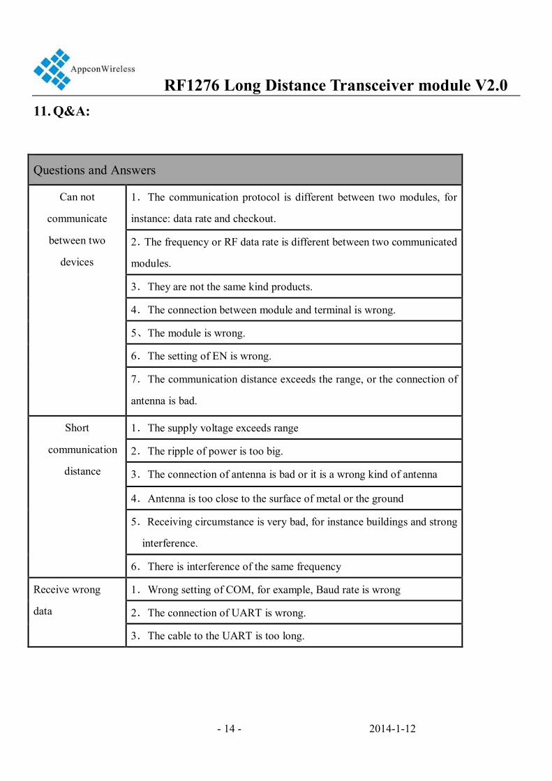
11. Q&A:
Questions and Answers
Can not
communicate
between two
devices
1.The communication protocol is different between two modules, for
instance: data rate and checkout.
2.The frequency or RF data rate is different between two communicated
modules.
3.They are not the same kind products.
4.The connection between module and terminal is wrong.
5、The module is wrong.
6.The setting of EN is wrong.
7.The communication distance exceeds the range, or the connection of
antenna is bad.
Short
communication
distance
1.The supply voltage exceeds range
2.The ripple of power is too big.
3.The connection of antenna is bad or it is a wrong kind of antenna
4.Antenna is too close to the surface of metal or the ground
5.Receiving circumstance is very bad, for instance buildings and strong
interference.
6.There is interference of the same frequency
Receive wrong
data
1.Wrong setting of COM, for example, Baud rate is wrong
2.The connection of UART is wrong.
3.The cable to the UART is too long.
RF1276 Long Distance Transceiver module V2.0
- 15 - 2014-1-12
APPCON WIRELESS TECHNOLOGIES CO.,LTD
Add: 28#, Longjin road,Xili zone, Nanshan District
Shenzhen P.R.C(518043)
TEL: +86-185 0309 2598
FAX: +86-755-83405160
Email: [email protected]
Web: http://www.appconwireless.com
AppconWireless technologies reserves the right to
make corrections, modifications, improvements and
other changes to its products and services at any
time and to discontinue any product or service
without notice. Customers are expected to visit
websites for getting newest product information
before placing orders.
These products are not designed for use in life
support appliances, devices or other products where
malfunction of these products might result in
personal injury. Customers using these products in
such applications do so at their own risk and agree
to fully indemnify AppconWireless technologies for
any damages resulting from improper use