Embed Size (px)
Citation preview
RFIC Test SystemTest Solution for Power Amplifier and Front End Module Characterization
DPD Reference Solution• Measure AM-AM and AM-PM using
modulated waveforms• Implement both lookup table (LUT) and
memory polynomial model (MPM) DPD algorithms
Characterization & Manufacturing Test Solutions• FPGA-based power level servo• 5x to 10x improvements in measurement
speed versus traditional instruments
System Features• Support for 802.11a/b/g/h/n/ac, UMTS,
LTE, and LTE-Advanced technologies• Getting started LV, C and .NET example
programs for DPD, Power Servo and Envelope Tracking
• Measure harmonics up to 26.5 GHz
Envelope Tracking Reference Solution• Industry leading baseband-to-RF
synchronization• Customizable Vccwaveform shaping• Advanced digital synchronization with DUT
TestStand Example Sequences
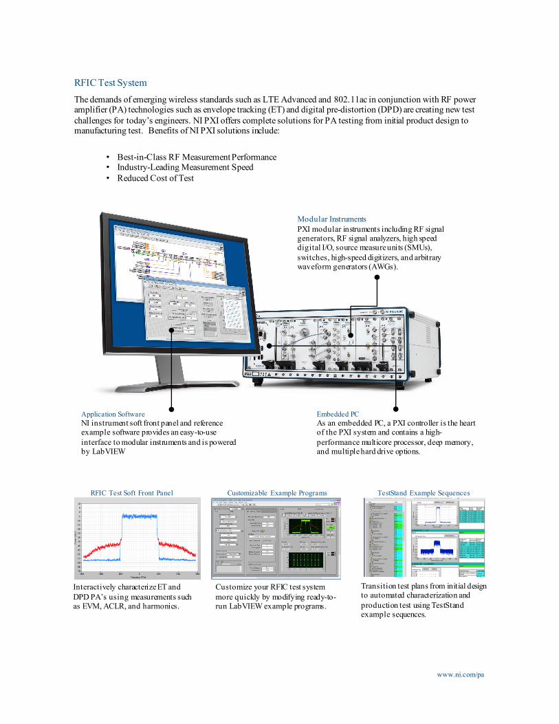
Transition test plans from initial design to automated characterization and production test using TestStandexample sequences.
RFIC Test Soft Front Panel
Interactively characterize ET and DPD PA’s using measurements such as EVM, ACLR, and harmonics.
www.ni.com/pa
Modular InstrumentsPXI modular instruments including RF signal generators, RF signal analyzers, high speed digital I/O, source measure units (SMUs), switches, high-speed digitizers, and arbitrary waveform generators (AWGs).
Application SoftwareNI instrument soft front panel and reference example software provides an easy-to-use interface to modular instruments and is powered by LabVIEW
Embedded PCAs an embedded PC, a PXI controller is the heart of the PXI system and contains a high-performance multicore processor, deep memory, and multiple hard drive options.
RFIC Test SystemThe demands of emerging wireless standards such as LTE Advanced and 802.11ac in conjunction with RF power amplifier (PA) technologies such as envelope tracking (ET) and digital pre-distortion (DPD) are creating new test challenges for today’s engineers. NI PXI offers complete solutions for PA testing from initial product design to manufacturing test. Benefits of NI PXI solutions include:
• Best-in-Class RF MeasurementPerformance• Industry-Leading Measurement Speed• Reduced Cost of Test
Customizable Example Programs
Customize your RFIC test system more quickly by modifying ready-to-run LabVIEW example programs.
www.ni.com/pa
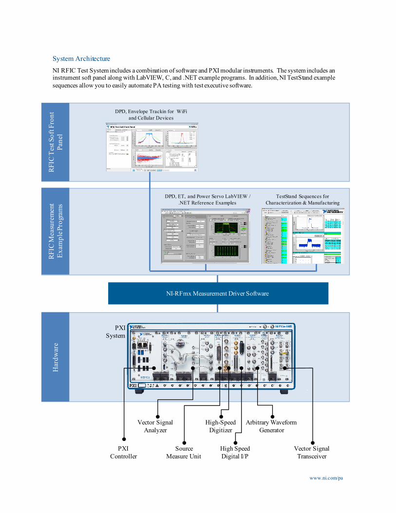
System ArchitectureNI RFIC Test System includes a combination of software and PXI modular instruments. The system includes an instrument soft panel along with LabVIEW, C, and .NET example programs. In addition, NI TestStand example sequences allow you to easily automate PA testing with test executive software.
PXI Controller
Arbitrary Waveform Generator
Vector Signal Analyzer
High-Speed Digitizer
Source Measure Unit
High Speed Digital I/P
PXI System
NI-RFmx Measurement Driver Software
DPD, Envelope Trackin for WiFiand Cellular Devices
TestStand Sequences forCharacterization & Manufacturing
DPD, ET, and Power Servo LabVIEW / .NET Reference Examples
RFIC
Tes
t Sof
t Fro
nt
Pane
lRF
IC M
easu
rem
ent
Exam
ple P
rogr
ams
Har
dwar
e
Vector Signal Transceiver
www.ni.com/pa
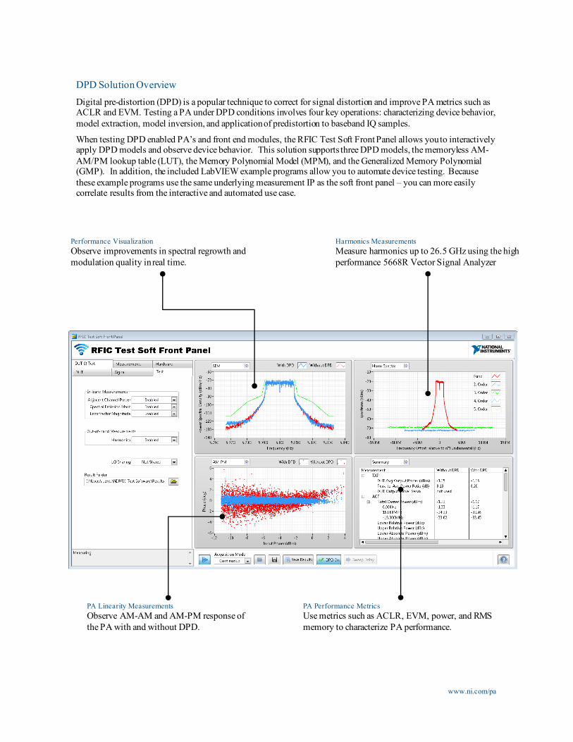
DPD Solution OverviewDigital pre-distortion (DPD) is a popular technique to correct for signal distortion and improve PA metrics such as ACLR and EVM. Testing a PA under DPD conditions involves four key operations: characterizing device behavior, model extraction, model inversion, and application of predistortion to baseband IQ samples.
When testing DPD enabled PA’s and front end modules, the RFIC Test Soft Front Panel allows you to interactively apply DPD models and observe device behavior. This solution supports three DPD models, the memoryless AM-AM/PM lookup table (LUT), the Memory Polynomial Model (MPM), and the Generalized Memory Polynomial (GMP). In addition, the included LabVIEW example programs allow you to automate device testing. Because these example programs use the same underlying measurement IP as the soft front panel – you can more easily correlate results from the interactive and automated use case.
Performance VisualizationObserve improvements in spectral regrowth and modulation quality in real time.
PA Linearity MeasurementsObserve AM-AM and AM-PM response of the PA with and without DPD.
PA Performance MetricsUse metrics such as ACLR, EVM, power, and RMS memory to characterize PA performance.
Harmonics MeasurementsMeasure harmonics up to 26.5 GHz using the high performance 5668R Vector Signal Analyzer
www.ni.com/pa
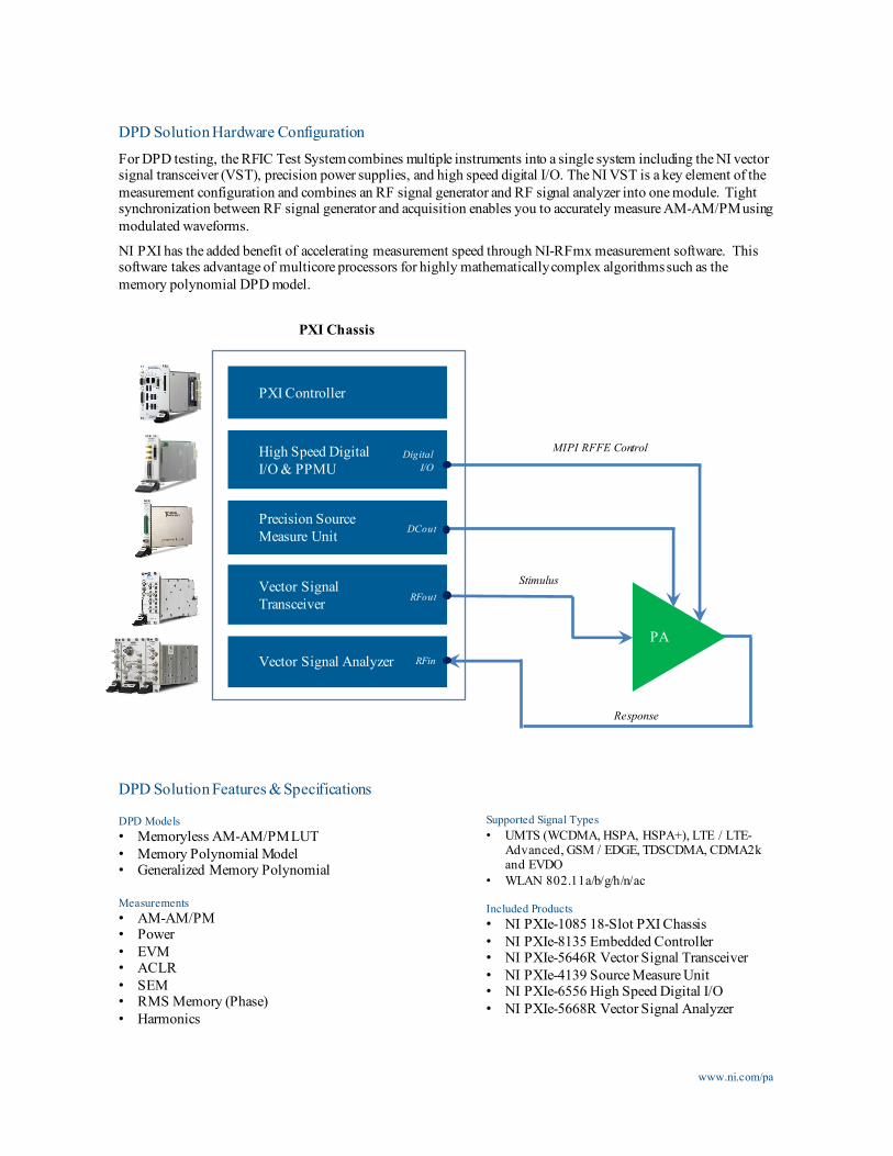
DPD Solution Hardware ConfigurationFor DPD testing, the RFIC Test System combines multiple instruments into a single system including the NI vector signal transceiver (VST), precision power supplies, and high speed digital I/O. The NI VST is a key element of the measurement configuration and combines an RF signal generator and RF signal analyzer into one module. Tight synchronization between RF signal generator and acquisition enables you to accurately measure AM-AM/PM using modulated waveforms.
NI PXI has the added benefit of accelerating measurement speed through NI-RFmx measurement software. This software takes advantage of multicore processors for highly mathematically complex algorithms such as the memory polynomial DPD model.
DPD Solution Features & Specifications
DPD Models• Memoryless AM-AM/PM LUT• Memory Polynomial Model• Generalized Memory Polynomial
Measurements• AM-AM/PM• Power• EVM• ACLR• SEM• RMS Memory (Phase)• Harmonics
Supported Signal Types• UMTS (WCDMA, HSPA, HSPA+), LTE / LTE-
Advanced, GSM / EDGE, TDSCDMA, CDMA2k and EVDO
• WLAN 802.11a/b/g/h/n/ac
Included Products• NI PXIe-1085 18-Slot PXI Chassis• NI PXIe-8135 Embedded Controller• NI PXIe-5646R Vector Signal Transceiver• NI PXIe-4139 Source Measure Unit• NI PXIe-6556 High Speed Digital I/O• NI PXIe-5668R Vector Signal Analyzer
Vector Signal Transceiver
PXI Chassis
MIPI RFFE ControlHigh Speed DigitalI/O & PPMU
DigitalI/O
Precision SourceMeasure Unit DCout
PA
Stimulus
Response
Vector Signal Analyzer
PXI Controller
RFin
RFout
www.ni.com/pa
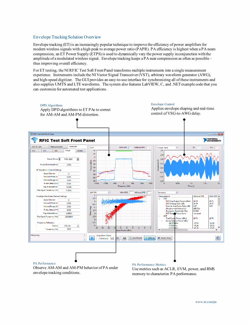
Envelope Tracking Solution Overview Envelope tracking (ET) is an increasingly popular technique to improve the efficiency of power amplifiers for modern wireless signals with a high peak to average power ratio (PAPR). PA efficiency is highest when a PA nears compression, an ET Power Supply (ETPS) is used to dynamically vary the power supply in conjunction with the amplitude of a modulated wireless signal. Envelope tracking keeps a PA near compression as often as possible –thus improving overall efficiency.
For ET testing, the NI RFIC Test Soft Front Panel transforms multiple instruments into a single measurement experience. Instruments include the NI Vector Signal Transceiver (VST), arbitrary waveform generator (AWG), and high-speed digitizer. The GUI provides an easy-to-use interface for synchronizing all of these instruments and also supplies UMTS and LTE waveforms. The system also features LabVIEW, C, and .NET example code that you can customize for automated test applications.
DPD AlgorithmsApply DPD algorithms to ET PAs to correct for AM-AM and AM-PM distortion.
Envelope ControlApplies envelope shaping and real-time control of VSG-to-AWG delay.
PA PerformanceObserve AM-AM and AM-PM behavior of PA under envelope tracking conditions.
PA Performance MetricsUse metrics such as ACLR, EVM, power, and RMS memory to characterize PA performance.
www.ni.com/pa
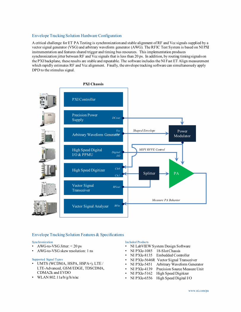
Envelope Tracking Solution Hardware ConfigurationA critical challenge for ET PA Testing is synchronization and stable alignment of RF and Vcc signals supplied by a vector signal generator (VSG) and arbitrary waveform generator (AWG). The RFIC Test System is based on NI PXI instrumentation and features shared trigger and timing bus resources. This implementation produces synchronization jitter between RF and Vcc signals that is less than 20 ps. In addition, by routing timing signals on the PXI backplane, these results are stable and repeatable. The software includes the NI Fast ET Align measurement which rapidly estimates RF and Vcc alignment. Finally, the envelope tracking software can simultaneously apply DPD to the stimulus signal.
Envelope Tracking Solution Features & Specifications
Vector Signal Transceiver
High Speed Digitizer
Measure PA Behavior
High Speed Digital I/O & PPMU
Arbitrary Waveform Generator
Precision Power Supply
PXI Controller
Power Modulator
RFout
PXI Chassis
DigitalI/O
DCout
VccOut
Ch1
Ch0
PA
MIPI RFFE Control
Splitter
Shaped Envelope
Synchronization• AWG-to-VSG Jitter: < 20 ps• AWG-to-VSG skew resolution: 1 ns
Supported Signal Types• UMTS (WCDMA, HSPA, HSPA+), LTE /
LTE-Advanced, GSM/EDGE, TDSCDMA, CDMA2k and EVDO
• WLAN 802.11a/b/g/h/n/ac
Included Products• NI LabVIEW System Design Software• NI PXIe-1085 18-Slot Chassis• NI PXIe-8135 Embedded Controller• NI PXIe-5646R Vector Signal Transceiver• NI PXIe-5451 Arbitrary Waveform Generator• NI PXIe-4139 Precision Source Measure Unit• NI PXIe-5162 High Speed Digitizer• NI PXIe-6556 High Speed Digital I/O
Vector Signal Analyzer RFin
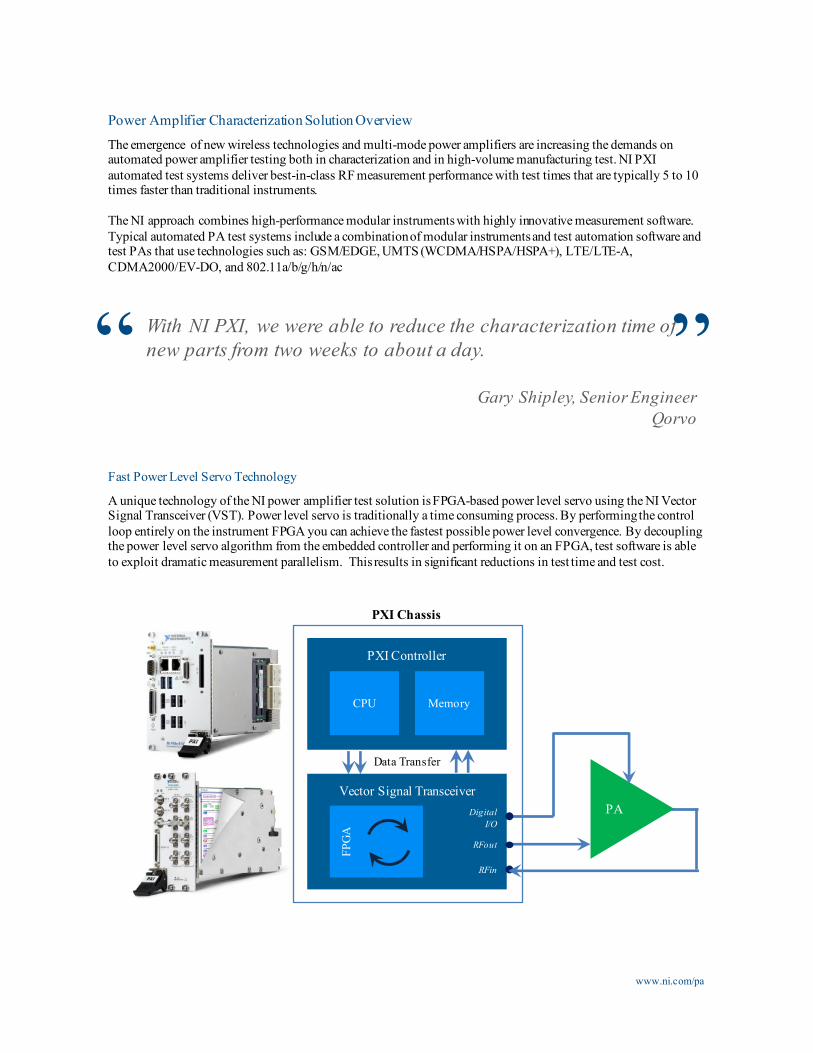
Power Amplifier Characterization Solution OverviewThe emergence of new wireless technologies and multi-mode power amplifiers are increasing the demands on automated power amplifier testing both in characterization and in high-volume manufacturing test. NI PXI automated test systems deliver best-in-class RF measurement performance with test times that are typically 5 to 10 times faster than traditional instruments.
The NI approach combines high-performance modular instruments with highly innovative measurement software. Typical automated PA test systems include a combination of modular instruments and test automation software and test PAs that use technologies such as: GSM/EDGE, UMTS (WCDMA/HSPA/HSPA+), LTE/LTE-A, CDMA2000/EV-DO, and 802.11a/b/g/h/n/ac
With NI PXI, we were able to reduce the characterization time of new parts from two weeks to about a day.
Gary Shipley, Senior EngineerQorvo
www.ni.com/pa
“ ”Fast Power Level Servo Technology
A unique technology of the NI power amplifier test solution is FPGA-based power level servo using the NI Vector Signal Transceiver (VST). Power level servo is traditionally a time consuming process. By performing the control loop entirely on the instrument FPGA you can achieve the fastest possible power level convergence. By decoupling the power level servo algorithm from the embedded controller and performing it on an FPGA, test software is able to exploit dramatic measurement parallelism. This results in significant reductions in test time and test cost.
Vector Signal TransceiverDigital
I/O
RFin
RFout
PXI Chassis
FPG
A
PA
Data Transfer
PXI Controller
CPU Memory
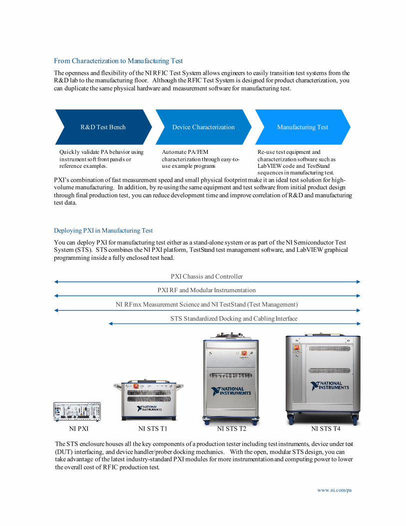
From Characterization to Manufacturing TestThe openness and flexibility of the NI RFIC Test System allows engineers to easily transition test systems from the R&D lab to the manufacturing floor. Although the RFIC Test System is designed for product characterization, you can duplicate the same physical hardware and measurement software for manufacturing test.
PXI’s combination of fast measurement speed and small physical footprint make it an ideal test solution for high-volume manufacturing. In addition, by re-using the same equipment and test software from initial product design through final production test, you can reduce development time and improve correlation of R&D and manufacturing test data.
Quickly validate PA behavior using instrument soft front panels or reference examples.
Automate PA/FEM characterization through easy-to-use example programs
Re-use test equipment and characterization software such as LabVIEW code and TestStandsequences in manufacturing test.
www.ni.com/pa
R&D Test Bench Device Characterization Manufacturing Test
NI STS T1NI PXI NI STS T4NI STS T2
PXI Chassis and Controller
PXI RF and Modular Instrumentation
NI RFmx Measurement Science and NI TestStand (Test Management)
STS Standardized Docking and Cabling Interface
Deploying PXI in Manufacturing Test
You can deploy PXI for manufacturing test either as a stand-alone system or as part of the NI Semiconductor Test System (STS). STS combines the NI PXI platform, TestStand test management software, and LabVIEW graphical programming inside a fully enclosed test head.
The STS enclosure houses all the key components of a production tester including test instruments, device under test (DUT) interfacing, and device handler/prober docking mechanics. With the open, modular STS design, you can take advantage of the latest industry-standard PXI modules for more instrumentation and computing power to lower the overall cost of RFIC production test.
www.ni.com/pa
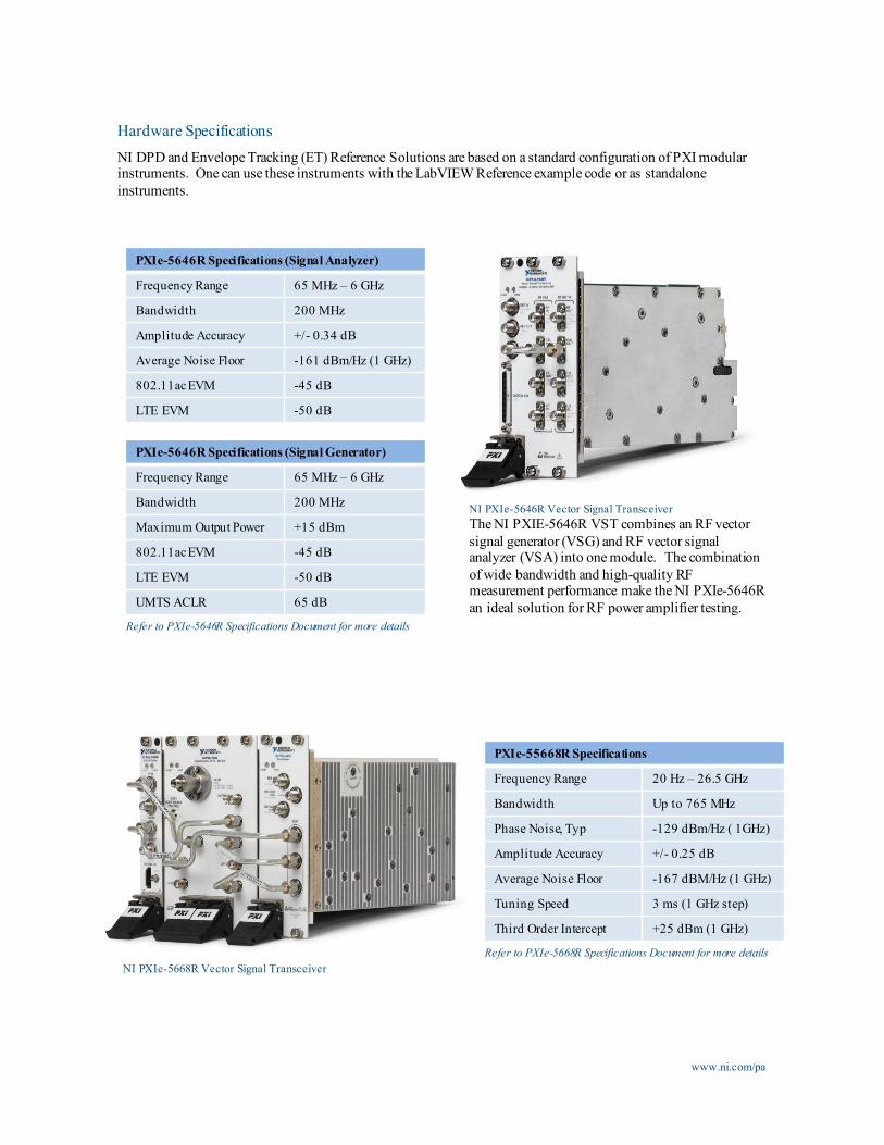
Hardware SpecificationsNI DPD and Envelope Tracking (ET) Reference Solutions are based on a standard configuration of PXI modular instruments. One can use these instruments with the LabVIEW Reference example code or as standalone instruments.
NI PXIe-5646R Vector Signal TransceiverThe NI PXIE-5646R VST combines an RF vector signal generator (VSG) and RF vector signal analyzer (VSA) into one module. The combination of wide bandwidth and high-quality RF measurement performance make the NI PXIe-5646R an ideal solution for RF power amplifier testing.
PXIe-5646R Specifications (Signal Generator)
Frequency Range 65 MHz – 6 GHz
Bandwidth 200 MHz
Maximum Output Power +15 dBm
802.11ac EVM -45 dB
LTE EVM -50 dB
UMTS ACLR 65 dB
PXIe-5646R Specifications (Signal Analyzer)
Frequency Range 65 MHz – 6 GHz
Bandwidth 200 MHz
Amplitude Accuracy +/- 0.34 dB
Average Noise Floor -161 dBm/Hz (1 GHz)
802.11ac EVM -45 dB
LTE EVM -50 dB
Refer to PXIe-5646R Specifications Document for more details
PXIe-55668R Specifications
Frequency Range 20 Hz – 26.5 GHz
Bandwidth Up to 765 MHz
Phase Noise, Typ -129 dBm/Hz ( 1GHz)
Amplitude Accuracy +/- 0.25 dB
Average Noise Floor -167 dBM/Hz (1 GHz)
Tuning Speed 3 ms (1 GHz step)
Third Order Intercept +25 dBm (1 GHz)
Refer to PXIe-5668R Specifications Document for more detailsNI PXIe-5668R Vector Signal Transceiver
www.ni.com/pa
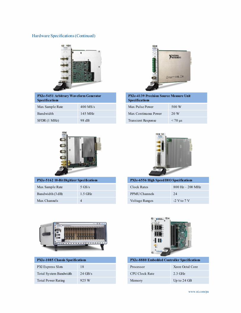
Hardware Specifications (Continued)
PXIe-8880 Embedded Controller Specifications
Processor Xeon Octal Core
CPU Clock Rate 2.3 GHz
Memory Up to 24 GB
PXIe-1085 Chassis Specifications
PXI Express Slots 18
Total System Bandwidth 24 GB/s
Total Power Rating 925 W
PXIe-6556 High Speed DIO Specifications
Clock Rates 800 Hz – 200 MHz
PPMU Channels 24
Voltage Ranges -2 V to 7 V
PXIe-5162 10-Bit Digitizer Specifications
Max Sample Rate 5 GS/s
Bandwidth (3 dB) 1.5 GHz
Max Channels 4
PXIe-5451 Arbitrary Waveform Generator Specifications
Max Sample Rate 400 MS/s
Bandwidth 145 MHz
SFDR (1 MHz) 98 dB
PXIe-4139 Precision Source Measure Unit Specifications
Max Pulse Power 500 W
Max Continuous Power 20 W
Transient Response < 70 µs
©2013 National Instruments. All rights reserved. LabVIEW, National Instruments, NI, ni.com, and NI CompactDAQ are trademarks of National Instruments. Other product and company names listed are trademarks or trade names of their respective companies. [20160729]
For more information on the RFIC Test system, email: [email protected]