Embed Size (px)
Citation preview

Rheology of dental waxes
L.C. McMillana, B.W. Darvellb,*aCraigielea, Quarriers Village, Bridge of Weir, Renfrewshire, UK
bPrince Philip Dental Hospital, 34 Hospital Road, Dental Materials Science, Faculty of Dentistry, The University of Hong Kong, Hong Kong,People’s Republic of China
Received 13 July 1999; received in revised form 25 January 2000; accepted 4 February 2000
Abstract
Objectives.The rheological properties of waxes are of considerable interest in dentistry, yet the only adopted method of characterizingthem in this respect is arbitrary and uninterpretable. The intention was to identify a means of doing so in an objective fashion and to apply it toa variety of products to establish the scope of behavior.
Method.The modified Stokes’ falling ball method was used to determine the apparent viscosity of 11 waxes over 25–458C under a widerange of loads and, therefore, strain rates.
Results.The falling ball method was demonstrated to be applicable over at least 7 orders of magnitude in viscosity, 7 in terminal velocity,and 3 in load. Waxes were shown to be pseudoplastic, lacking any identifiable yield point and having marked departures from Newtonianbehavior. The pseudoplasticity followed a power law, the exponent of which (the pseudoplasticity parameter) was temperature dependent in acomplex manner, but which showed a definite relationship to the reduced temperature, referred to the liquidus temperature. A master curvecould not be constructed because of this variation, but also because of discontinuities in the isothermal contours attributed to stress-melting ofcomponents of the wax mixture. Stress-melting may in part account for the pseudoplasticity.
Significance.A standardized viscosity number has been defined at 308C and under 10 N load as the common logarithm of the falling ballapparent viscosity in order to characterize the flow behavior of dental waxes with a single convenient number. The shear thinning exponent,the reciprocal of the pseudoplasticity parameter, provides a similarly convenient measure of the stress-sensitivity of the wax. Direct objectivecomparison of the rheology of dental waxes may now be made, facilitating selection by the user through appropriate labeling.q 2000Academy of Dental Materials. Published by Elsevier Science Ltd. All rights reserved.
Keywords: Dentistry; Wax; Rheology
1. Introduction
The utility of dental waxes stems from several factors:they are cheap, non-toxic, low melting, weak solids that canbe readily shaped and molded. They are used for some of thehighest precision work in dentistry, as well as cruder tasks,yet they have the worst thermal expansion coefficients of allin dentistry [1–4]. Where such dimensional changes areconstrained, flow must ensue. Worse, expansion dependson the previous stress history [1]. This is attributable to astress relaxation process which, being time-dependent,again makes the problem one of rheology.
Dental waxes are always mixtures of compounds withvarious melting points. The mechanical behavior is there-fore temperature sensitive, depending on composition andnumber of phases [5]. Supposedly, this allows properties to
be manipulated to tailor the product to suit the task [6,7].The working environment provides other demands. Whethertemperate or tropical, air conditioned or not, extra-oral flowwill be ‘room temperature’-sensitive.
While flow is important in every dental wax application,complicated by residual stress effects [8–10] and thermalexpansion [11], there exists no rigorous flow specification,and no attempt has been made to characterize these mater-ials rheologically. Despite the “urgent” need for “stan-dardized testing methods” being recognized as long ago as1941 [12], waxes are mentioned in only two of the Inter-national Organization for Standardization’s (ISO) manystandards, neither in a rheological context. No other stan-dardization work has been located in other fields.
Two American Dental Association (ADA) Specificationsrelate to dental waxes. ADA 4 [13], adopted by the ISO [14],refers to Dental Inlay Casting waxes. It has been revised anumber of times [15,16] since its introduction [17]. Dentalbaseplate/modeling waxes are covered by ADA 24 [18],currently under revision for ISO adoption [19]. Rather old
Dental Materials 16 (2000) 337–350
dentalmaterials
0109-5641/00/$ – see front matterq 2000 Academy of Dental Materials. Published by Elsevier Science Ltd. All rights reserved.PII: S0109-5641(00)00026-9
www.elsevier.com/locate/dental
* Corresponding author. Tel.:1 852-2859-0303; fax: 1 852-2548-9464.
E-mail address:[email protected] (B.W. Darvell).
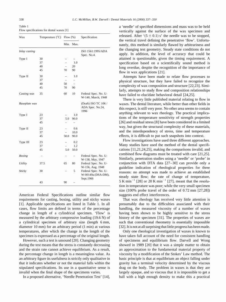
American Federal Specifications outline similar flowrequirements for casting, boxing, utility and sticky waxes[1]. Applicable specifications are listed in Table 1. In allcases, flow limits are defined in terms of the percentagechange in length of a cylindrical specimen. ‘Flow’ ismeasured by the arbitrary compressive loading (19.6 N) ofa cylindrical specimen of arbitrary size (length 6 mm,diameter 10 mm) for an arbitrary period (1 min) at varioustemperatures, after which the change in the length of thespecimen is expressed as a percentage of the original length.
However, such a test is unsound [20]. Changing geometryduring the test means that the stress is constantly decreasingand the strain rate cannot achieve equilibrium. As a result,the percentage change in length is a meaningless value. Asan arbitrary figure its usefulness is strictly only qualitative inthat it indicates whether or not the material falls within thestipulated specifications. Its use in a quantitative sense isinvalid when the final shape of the specimens varies.
In a proposed alternative, ‘Needle Penetration Test’ [14],
a ‘needle’ of specified dimensions and mass was to be heldvertically against the surface of the wax specimen andreleased. After ‘�5^ 0:1� s’ the needle was to be stopped,the vertical travel defining the penetrative ‘flow’. Unfortu-nately, this method is similarly flawed by arbitrariness andthe changing test geometry. Steady state conditions do notapply. In addition, the level of accuracy that could beattained is questionable, given the timing requirement. Aspecification based on a scientifically sound method islong overdue, despite the recognition of the importance offlow in wax applications [21].
Attempts have been made to relate flow processes tophysical structure, but they have failed to recognize thecomplexity of wax composition and structure [22,23]. Simi-larly, attempts to study flow and composition relationshipshave failed to elucidate behavioral detail [24,25].
There is very little published material relating to flow inwaxes. The dental literature, while better than other fields inthis respect, is still very poor. No other area seems to containanything relevant to wax rheology. The practical implica-tions of the temperature sensitivity of strength properties[26] and residual stress [8] have been considered in a limitedway, but given the structural complexity of these materials,and the interdependency of stress, time and temperatureeffects, it is difficult to put such snapshots into context.
Flow investigations have used three different approaches.Many studies have used the method of the dental specifi-cations [11,21,24,25], making the comparisons invalid, andcombined flow diagrams must be treated with care [21,25].Similarly, penetration studies using a ‘needle’ or ‘probe’ inconjunction with DTA data [27–30] can provide only aguideline indication of rheological properties for threereasons: no attempt was made to achieve an establishedsteady state flow; the rate of change of temperature,5 K min21 [28] or 20 K min21 [27], meant that the resolu-tion in temperature was poor; while the very small specimensize (100% probe travel of the order of 0.72 mm [27,28])suggests end effect interferences.
That wax rheology has received very little attention ispresumably due to the difficulties associated with theirhandling, the measured viscosity of a number of waxeshaving been shown to be highly sensitive to the stresshistory of the specimen [31]. The properties of waxes aresuch that conventional rheometry is essentially impossible[32]. It is not at all surprising that little progresshas been made.
Only one rheological investigation of waxes is known tohave taken full account of the need for consistent handlingof specimens and equilibrium flow. Darvell and Wongshowed in 1989 [20] that it was a simple matter to obtainan approximation to the fundamental material property ofviscosity by a modification of the Stokes’ Law method. Thebasic principle is that at equilibrium an object falling undergravity has a terminal velocity determined by the viscousdrag on the body. The problem in waxes is that they arelargely opaque, and so viscous that it is impossible to get aball with a high enough density to make this a practical
L.C. McMillan, B.W. Darvell / Dental Materials 16 (2000) 337–350338
Table 1Flow specifications for dental waxes [1]
Wax Temperature (8C) Flow (%) Specification
Min. Max.
Inlay casting ISO 1561:1995/ADASpec. No.4.
Type I 30 – –37 – 1.040 – 2045 70 90
Type II 30 – 1.037 – –40 50 –45 70 90
Casting wax 35 60 10 Federal Spec. No. U-W-140, March, 1948
Baseplate wax (Draft) ISO TC 106 /ADA Spec. No.24,1996
Type I 23 – 1.037 5.0 90.045 – –
Type II 23 – 0.637 – 10.045 50.0 90.0
Type III 23 – 0.237 – 1.245 5.0 50.0
Boxing – – – Federal Spec. No. U-W-138, May, 1947
Utility 37.5 65 80 Federal Spec. No. U-W-156, Aug. 1948
Sticky 30 – 5 Federal Spec. No. U-W-00149a (DSA-DM),Sept.1966
43 90 –
proposition. The solution is to give the ball a push, relyingon the fact that the wax does not close in around the ball andgive an extra resistance by dragging on the push rod. In thisway it was possible to get detailed data on wax viscosity as afunction of temperature and load. Notice that, even in thatpreliminary work, it was evident that waxes showed a stress-dependent viscosity, which made it clear that the ADA flowtest was unserviceable.
With good temperature control and consistent specimenannealing, the technique was found to be an effective way ofapplying a constant stress to a wax specimen with bothequilibrium flow and consistent rates of strain beingreported [20]. An ‘apparent’ viscosity was measured(‘apparent’ because of the slight deviation of the test con-ditions from those on which the theory was based) rangingbetween 104 and 1010 Pa s. This showed it to be a relativelyversatile technique, and applicable to the study of the manydifferent types of dental and non-dental waxes, and there-fore this method was followed for the present work.
The purpose was then to apply this method to the rheologicalcharacterization of waxes with a view to assisting user selectionas well as the study of composition–handling relationships.
2. Materials and methods
The general method already described was followed [20].
A 3 mm ball was driven into the wax specimen by a 1 mmdiameter tool steel shaft under a deadweight load which wasvaried from 10 g to 8 kg. Specimens were immersed in anaccurately depth-controlled water bath, the temperature ofwhich was varied from 25 to 458C in 5 K steps (wherefeasible), controlled to 0.01 K, although in some casesother intermediate temperatures were tested when criticalevents were apparent. The buoyancy effect of the immersedstem of the load string was taken into account. The range ofwaxes tested was chosen to be representative of the scope ofapplications within dentistry (Table 2).
Unlike the previous work [20], a non-contact means ofmonitoring the position of the load column was adopted toavoid the extra and variable load that displacement probeswould provide, i.e. a vernier cathetometer (model 2202,PTI, Liss, Hants, UK), reading to 0.01 mm. This wasapplied whenever possible. However, for the lowest ratesof fall the resolution was inadequate and six low-load (2–20 g), side-acting displacement transducers were used(model 499, Mercer, St. Albans, Herts, UK), using a switchbox (Probe Selector, Mercer) and digital display unit(122DM, Mercer). The latter could display 1999 or^199.9mm, i.e. with resolutions of 1 and 0.1mm, respec-tively. The extra load was taken into account as appropriate.The probes’ calibration was done by reference to a drummicrometer (Russell Gauges, Romford, Essex, UK) to aresolution of 0.05mm.
L.C. McMillan, B.W. Darvell / Dental Materials 16 (2000) 337–350 339
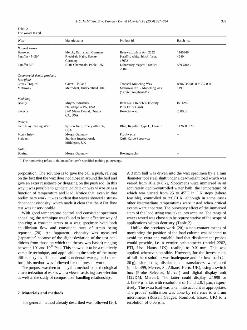
Table 2The waxes tested
Wax Manufacturer Product id. Batch no.
Natural waxesBeeswax Merck, Darmstadt, Germany Beeswax, white Art. 2252 1165869Paraffin 45–50a Riedel-de Hae¨n, Seelze,
GermanyParaffin, white, block form,18633
4249
Paraffin 55a BDH Chemicals, Poole, UK Laboratory reagent Product29840
5893700C
Commercial dental productsBaseplateCavex Tropical Cavex, Holland Tropical Modeling Wax 880603/2002.89/C05-008Metrowax Metrodent, Huddersfield, UK Metrowax No. 2 Modelling wax
(“stretch toughened”)1191
ModelingBeauty Moyco Industries,
Philadelphia PA, USAItem No. 116-56630 (BeautyPink Extra Hard)
lot 1249
Korecta D-R Miner Dental, OrindaCA, USA
Korecta-Wax 280981
PatternKerr Inlay Casting Wax Sybron Kerr, Emeryville CA,
USABlue, Regular, Type C, Class 1 1126801329
Morsa Inlay Morsa, Germany Profilwachs –Staident Staident International,
Middlesex, UKQuik-Karve Superwax –
UtilityBoxing Morsa, Germany Boxingwachs –
a The numbering refers to the manufacturer’s specified melting point/range.
Wax cylinders 30 mm diameter× 30 mm high wereprepared in brass molds by gradually and slowly runningin just-molten wax, and allowing solidification from thebase up, ensuring that the wax was always molten at theperiphery and wetting the mold wall by warming the topedge of the mold with a small non-smoky flame. The for-mation of a shrinkage pipe was similarly avoided, remeltingthe surface of the wax if necessary with the brief applicationof the flame. The mold was well-overfilled. One-shot fillingtechniques, as used by the ADA/ISO specification methods,could not produce reliably flaw-free specimens.
Given that waxes were already known to be history-dependent in their rheology, great pains were taken toanneal specimens at the test temperature. In addition,compensation for thermal expansion and shrinkage had tobe made: molds needed to be properly full with no gaps atthe periphery, and any frozen stresses relieved. Annealingwas therefore commenced under hydrostatic load in an
apparatus from which the wax could not be extruded easily,the various parts of the mold, sheath and load cap being snugfits. This was done by stacking sets of six specimens in twolayers of three between load plates in a hydraulic press,using a total load maintained at 10–20 kN, according tothe softness of the wax at that temperature (which wascontrolled to ^0.1 K). After about 40 h this load wasremoved, and not less than 10 d was then allowed for furtherannealing at the test temperature. Specimens were rejectedif no excess wax was present about the mold edge, as thiswas taken as indicating absence of the required hydrostaticload at the end of the first stage because of excessiveextrusion.
Only data for ball positions in the middle third of thespecimen depth were collected to avoid end effects. Theball was driven to an appropriate position to start under ahigher load if necessary, but a specimen’s temperature wasnever varied. Position data were collected at times recorded
L.C. McMillan, B.W. Darvell / Dental Materials 16 (2000) 337–350340
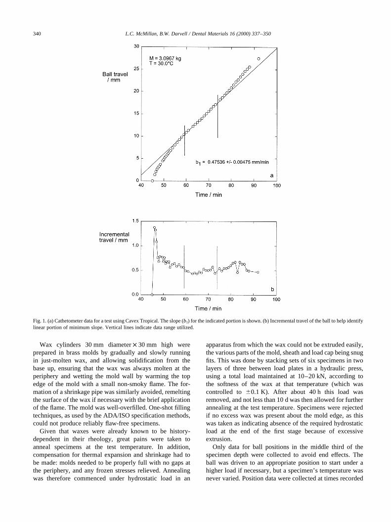
Fig. 1. (a) Cathetometer data for a test using Cavex Tropical. The slope (b1) for the indicated portion is shown. (b) Incremental travel of the ball to help identifylinear portion of minimum slope. Vertical lines indicate data range utilized.
in minutes to the nearest 2 s. When the fall rate had stabi-lized for an adequate period, the slope of the linear portioncould be determined by linear regression (least squares fit),that is, the terminal velocity (Fig. 1).
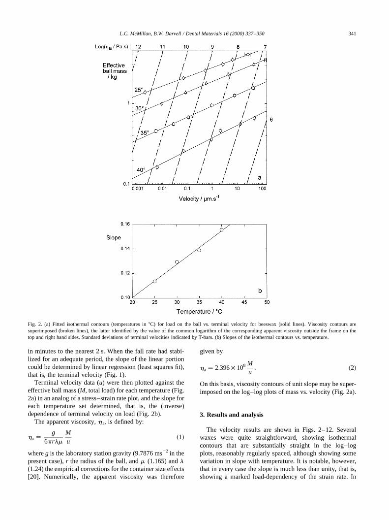
Terminal velocity data (u) were then plotted against theeffective ball mass (M, total load) for each temperature (Fig.2a) in an analog of a stress–strain rate plot, and the slope foreach temperature set determined, that is, the (inverse)dependence of terminal velocity on load (Fig. 2b).
The apparent viscosity,ha, is defined by:
ha � g6prlm
Mu
�1�
whereg is the laboratory station gravity (9.7876 ms22 in thepresent case),r the radius of the ball, andm (1.165) andl(1.24) the empirical corrections for the container size effects[20]. Numerically, the apparent viscosity was therefore
given by
ha � 2:396× 108 Mu: �2�
On this basis, viscosity contours of unit slope may be super-imposed on the log–log plots of mass vs. velocity (Fig. 2a).
3. Results and analysis
The velocity results are shown in Figs. 2–12. Severalwaxes were quite straightforward, showing isothermalcontours that are substantially straight in the log–logplots, reasonably regularly spaced, although showing somevariation in slope with temperature. It is notable, however,that in every case the slope is much less than unity, that is,showing a marked load-dependency of the strain rate. In
L.C. McMillan, B.W. Darvell / Dental Materials 16 (2000) 337–350 341
Fig. 2. (a) Fitted isothermal contours (temperatures in8C) for load on the ball vs. terminal velocity for beeswax (solid lines). Viscosity contours aresuperimposed (broken lines), the latter identified by the value of the common logarithm of the corresponding apparent viscosity outside the frame on thetop and right hand sides. Standard deviations of terminal velocities indicated by T-bars. (b) Slopes of the isothermal contours vs. temperature.
addition, there is no suggestion in any of these results thatthere was a yield point, in other words a load below whichthere was no flow. Taken together, this means that the waxescan be described as pseudoplastic. The regularity of thestraight line isothermal contours suggests that a power–curve function can be used to describe the variation:
M � aub �3�
or equivalently
ha / Mu� aub21 �4�
indicating the strain rate sensitivity of the apparent viscos-ity. The exponentb may therefore be termed the pseudo-plasticity parameter, as descriptive of a property of the waxat a given temperature.
L.C. McMillan, B.W. Darvell / Dental Materials 16 (2000) 337–350342
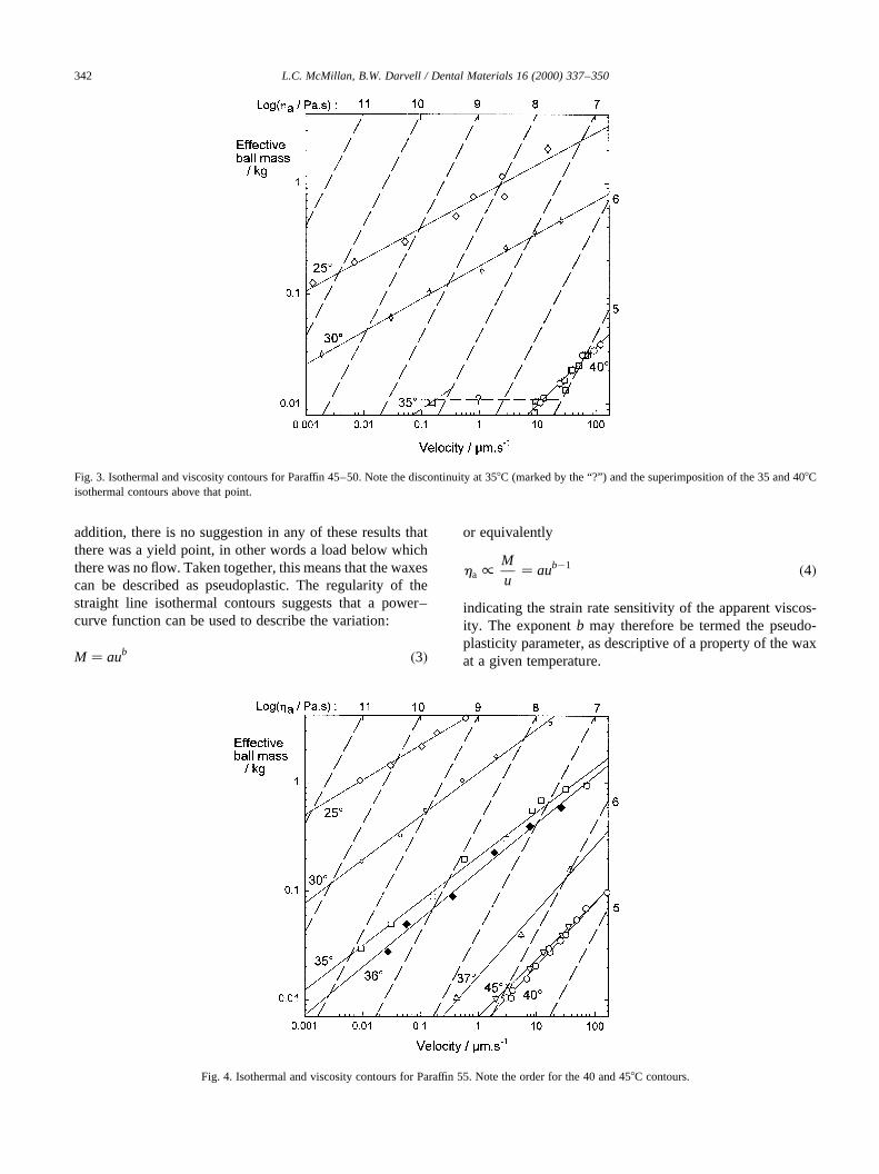
Fig. 3. Isothermal and viscosity contours for Paraffin 45–50. Note the discontinuity at 358C (marked by the “?”) and the superimposition of the 35 and 408Cisothermal contours above that point.
Fig. 4. Isothermal and viscosity contours for Paraffin 55. Note the order for the 40 and 458C contours.
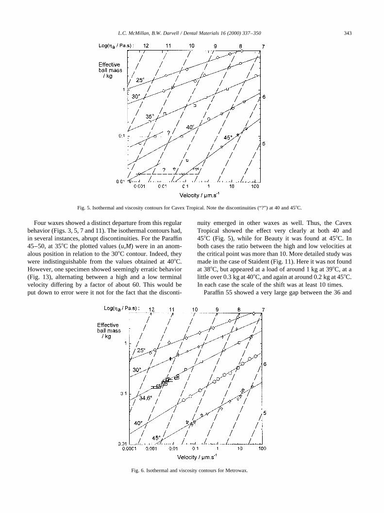
Four waxes showed a distinct departure from this regularbehavior (Figs. 3, 5, 7 and 11). The isothermal contours had,in several instances, abrupt discontinuities. For the Paraffin45–50, at 358C the plotted values (u,M) were in an anom-alous position in relation to the 308C contour. Indeed, theywere indistinguishable from the values obtained at 408C.However, one specimen showed seemingly erratic behavior(Fig. 13), alternating between a high and a low terminalvelocity differing by a factor of about 60. This would beput down to error were it not for the fact that the disconti-
nuity emerged in other waxes as well. Thus, the CavexTropical showed the effect very clearly at both 40 and458C (Fig. 5), while for Beauty it was found at 458C. Inboth cases the ratio between the high and low velocities atthe critical point was more than 10. More detailed study wasmade in the case of Staident (Fig. 11). Here it was not foundat 388C, but appeared at a load of around 1 kg at 398C, at alittle over 0.3 kg at 408C, and again at around 0.2 kg at 458C.In each case the scale of the shift was at least 10 times.
Paraffin 55 showed a very large gap between the 36 and
L.C. McMillan, B.W. Darvell / Dental Materials 16 (2000) 337–350 343
Fig. 5. Isothermal and viscosity contours for Cavex Tropical. Note the discontinuities (“?”) at 40 and 458C.
Fig. 6. Isothermal and viscosity contours for Metrowax.

378C contours, suggestive of a similar effect operating.However, neither a high enough load could be used at368C, nor a low enough load at 378C, so this could not bedefinitely established. A further peculiarity was neverthe-less evident: the 458C contour was on the ‘wrong side’ ofthat for 408C. This remains unexplained.
Korecta showed very large separations between the 25, 30and 358C contours although no evidence of a discontinuitywas found. Unfortunately, rather large differences occurredbetween different sets of runs at 30 and 358C (solid and open
symbols in Fig. 8), suggesting great sensitivity to someinsufficiently controlled variable.
The pseudoplasticity parameter was further considered.On the basis that flow is a molecular process, and that assuch must be diffusive and therefore associated with anactivation energy, the variation of b with test temperaturewas examined, but with no apparent pattern emerging.However, plotting against reduced temperature,TR, definedas the test temperature as a fraction of the liquidus tempera-ture (i.e. the temperature of the highest melting event in the
L.C. McMillan, B.W. Darvell / Dental Materials 16 (2000) 337–350344
Fig. 7. Isothermal and viscosity contours for Beauty. Note the discontinuity (“?”) at 458C.
Fig. 8. Isothermal and viscosity contours for Korecta.
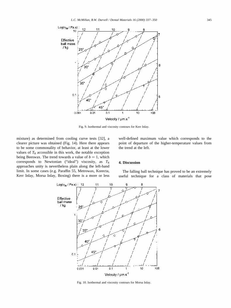
mixture) as determined from cooling curve tests [32], aclearer picture was obtained (Fig. 14). Here there appearsto be some commonality of behavior, at least at the lowervalues ofTR accessible in this work, the notable exceptionbeing Beeswax. The trend towards a value ofb� 1; whichcorresponds to Newtonian (“ideal”) viscosity, asTR
approaches unity is nevertheless plain along the left-handlimit. In some cases (e.g. Paraffin 55, Metrowax, Korecta,Kerr Inlay, Morsa Inlay, Boxing) there is a more or less
well-defined maximum value which corresponds to thepoint of departure of the higher-temperature values fromthe trend at the left.
4. Discussion
The falling ball technique has proved to be an extremelyuseful technique for a class of materials that pose
L.C. McMillan, B.W. Darvell / Dental Materials 16 (2000) 337–350 345
Fig. 9. Isothermal and viscosity contours for Kerr Inlay.
Fig. 10. Isothermal and viscosity contours for Morsa Inlay.
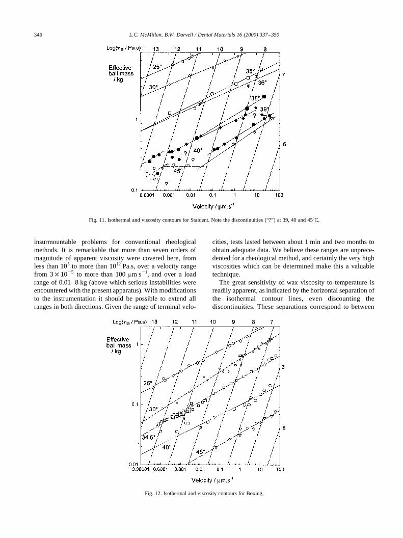
insurmountable problems for conventional rheologicalmethods. It is remarkable that more than seven orders ofmagnitude of apparent viscosity were covered here, fromless than 105 to more than 1012 Pa.s, over a velocity rangefrom 3× 1025 to more than 100mm s21, and over a loadrange of 0.01–8 kg (above which serious instabilities wereencountered with the present apparatus). With modificationsto the instrumentation it should be possible to extend allranges in both directions. Given the range of terminal velo-
cities, tests lasted between about 1 min and two months toobtain adequate data. We believe these ranges are unprece-dented for a rheological method, and certainly the very highviscosities which can be determined make this a valuabletechnique.
The great sensitivity of wax viscosity to temperature isreadily apparent, as indicated by the horizontal separation ofthe isothermal contour lines, even discounting thediscontinuities. These separations correspond to between
L.C. McMillan, B.W. Darvell / Dental Materials 16 (2000) 337–350346
Fig. 11. Isothermal and viscosity contours for Staident. Note the discontinuities (“?”) at 39, 40 and 458C.
Fig. 12. Isothermal and viscosity contours for Boxing.
20 and 300 times greater viscosity for a 58 fall intemperature.
It is also now very apparent that the waxes tested arestrongly non-Newtonian in their flow behavior, and the like-lihood is that all waxes will show this. The departure is inthe sense of pseudoplasticity: for increasing load, the shearstrain rate is disproportionately greater. This is possibly onereason why wax is so successful as a modeling material: itresponds to pressure in a rather sensitive manner, literally,
the harder it is pushed the softer it appears to be. This effectmay also be enhanced by the discontinuous behavior shownby some waxes, a dramatic increase in the deformation ratefor only minor increases in load. However, since this effectis only apparent for easily accessible loads over a smallrange of temperature, and depending on the wax, it seemsunlikely to be amenable to user control. Nevertheless, theease of carving waxes, where the stress under a sharp edgewould be very high, must be largely due to this property.
L.C. McMillan, B.W. Darvell / Dental Materials 16 (2000) 337–350 347
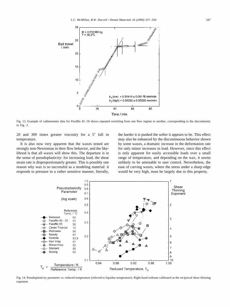
Fig. 13. Example of cathetometer data for Paraffin 45–50 shows repeated switching from one flow regime to another, corresponding to the discontinuityin Fig. 3.
Fig. 14. Pseudoplasticity parameter vs. reduced temperature (referred to liquidus temperature). Right-hand ordinate calibrated as the reciprocal shear thinningexponent.
The pseudoplasticity parameter is not a very intuitivelyinterpretable quantity. However, its inverse has a clearermeaning: the number of orders of magnitude increase inball velocity for a ten-fold increase in load. This may betermed the ‘shear thinning exponent’ and is shown as suchin the recalibrated right-hand ordinate of Fig. 14. At a stan-dardized temperature such a number could provide a usefulguide to the expected behavior of a product.
The discontinuity in the isothermal contours may be attri-butable to the melting under stress of one component of thewax mixture, much as ice melts under the skater’s blade,although attempts to identify such events with features ofthe wax’s cooling curve have not yet been successful, prob-ably due to the reciprocal nature of the temperature of theevent and the load applied (cf. Fig. 11). Extremely low loadswould be necessary to approach the limiting case of theactual temperature of the event.
The effect could easily be confused with the existence of ayield point, which it resembles, except that the flow below thatload continues in a regular and consistent fashion. Its existencedoes, however, draw attention to the problems of arbitrary waxflow tests, as described above. Suppose that initially, at theselected test temperature, the load exceeds the value requiredfor the flow switch. Deformation is then rapid. But thediameter of the piece increases, reducing the stress in propor-tion to the height, so that at some point the switch is passed, theviscosity increases by a factor of, say, 10 and the deformationrate drops abruptly. The effect would be to give the appearanceof a specific critical temperature at which ‘flow’ is large,evidently not a satisfactory description of behavior.
The size of the discontinuity in these cases suggests arather large proportion of the corresponding component. Itmight be possible to demonstrate this relationship with care-fully formulated experimental blends, assuming that suffi-ciently pure individual components were available.However, the effect does suggest one possible reason forthe pseudoplasticity of waxes in general. It is relevant tonotice that dental waxes are very complex mixtures, perhapscontaining hundreds of compounds (furthermore, being
mostly natural products, they are also subject to uncon-trolled variation). The melting point of waxes dependsonly slowly on molecular weight and other factors, so thatin a typical mixture there will be very many closely spacedmelting points, even if such matters as solid solutions arediscounted. Each such component, or at least each phase,would contribute to the rheological behavior in that as thetemperature is raised they would melt successively, causingthe viscosity to fall. However, if a number of them are alsocapable of stress melting, the effect would be that of theobserved pseudoplasticity–viscosity falling dramaticallywith stress. The velocity switches seen for Staident andthe other waxes are then merely larger scale events of thesame kind. By the same token, the discontinuities for minorcomponents would be small and thus not detectable at theresolution of the present work, although they might appearas a series of smaller steps in the isothermal contours.
Given that, the apparent good linearity of the isothermallines means that a power-law model can probably be usedgenerally to represent the pseudoplasticity. However, thevariation with temperature of the value of the pseudoplas-ticity parameter means that a ‘master curve’ for temperatureand strain rate cannot be constructed, which complicates thetask of wax rheological characterization.
It is a point of some considerable practical significancethat there is no load at which flow does not occur. That is tosay, there is no true yield point in evidence for any of thewaxes tested. This means that wax patterns can be expectedto distort under any load whatsoever, including internal‘frozen’ stresses. Obviously, the extent of this is time-,temperature- and history-dependent, but there can be no‘safe’ circumstances except to follow all the normal precau-tions assiduously to minimize the effects. This may be diffi-cult in the case of casting investments where expansion isrequired and the process is conducted at an elevatedtemperature [33]. This behavior also makes it difficult tointerpret reported values of proportional limit, compressivestrength and modulus of elasticity [26], which concepts arenow seen to be of dubious applicability. It is even moredifficult to see how their calculations for wax patterns ‘with-out distortion’ could be meaningful.
One of the motivations of this work was the need toidentify a rheological characteristic number that wouldenable selection (and indeed design) of products to bedone on a rational basis according to circumstances andpurpose. It is apparent though that the variation in pseudo-plasticity parameter and the presence of the discontinuitiesmakes impossible the master curve, which would enablesuch a characterization. Previous attempts to do this [22]are therefore probably unreliable. Thus, load and tempera-ture must be specified. It is now suggested that 10 N and308C be the reference values on the grounds that
1. they are readily accessible values;2. the terminal velocities expected are accessible without
special arrangements;
L.C. McMillan, B.W. Darvell / Dental Materials 16 (2000) 337–350348
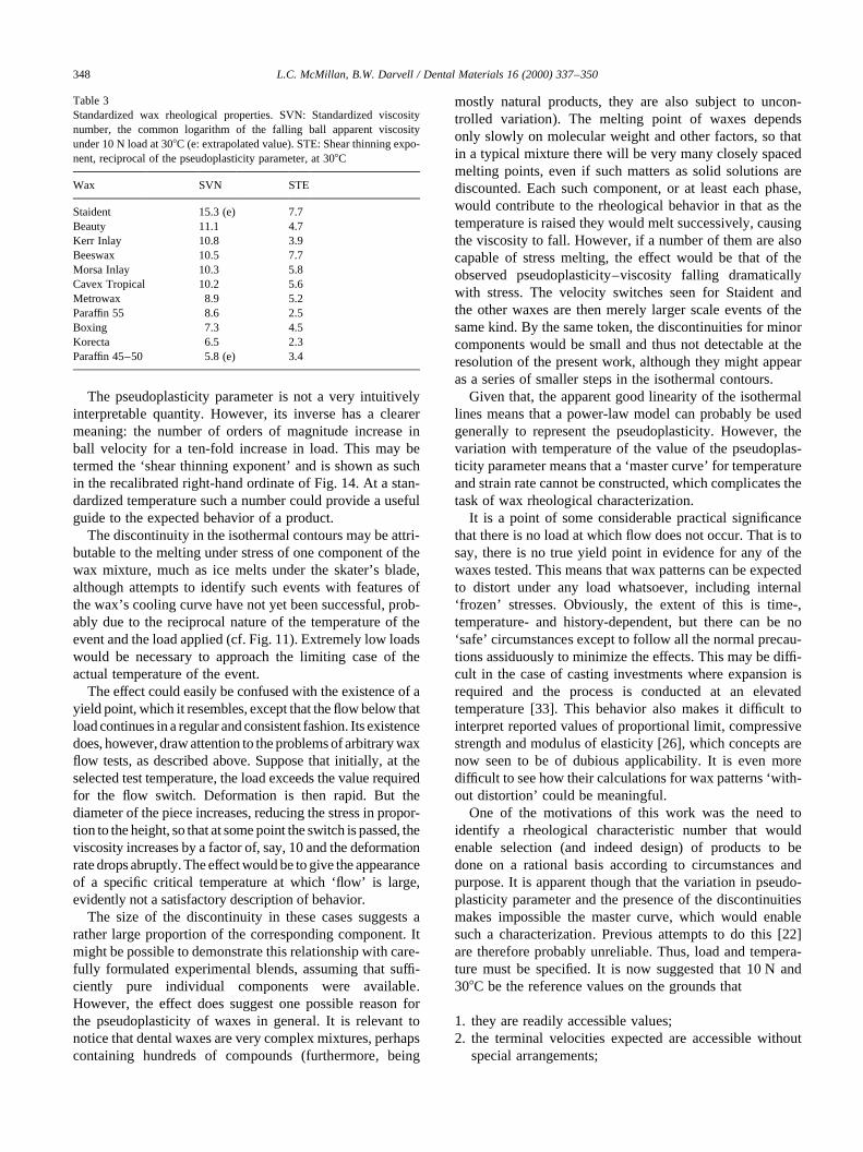
Table 3Standardized wax rheological properties. SVN: Standardized viscositynumber, the common logarithm of the falling ball apparent viscosityunder 10 N load at 308C (e: extrapolated value). STE: Shear thinning expo-nent, reciprocal of the pseudoplasticity parameter, at 308C
Wax SVN STE
Staident 15.3 (e) 7.7Beauty 11.1 4.7Kerr Inlay 10.8 3.9Beeswax 10.5 7.7Morsa Inlay 10.3 5.8Cavex Tropical 10.2 5.6Metrowax 8.9 5.2Paraffin 55 8.6 2.5Boxing 7.3 4.5Korecta 6.5 2.3Paraffin 45–50 5.8 (e) 3.4
3. the choice of temperature avoids known velocityswitches;
4. the choice of temperature represents a compromise hand-ling temperature rather than an assumed room tempera-ture;
5. in addition, and in view of the wide range of viscositiesencountered, the common logarithm of the apparent vis-cosity has a convenient range of values under theseconditions.
The resultant characterizing value may be termed theStandardized Viscosity Number (SVN). By way of illustra-tive example, the corresponding values, extracted from Figs.2–12, are given in Table 3. Greater precision than one deci-mal place would be unnecessary and probably not attainablein any practical context. It will be noticed that under thisarrangement, the values for the two waxes at the extremeswere not in fact determined directly but had to be extrapo-lated. This is not surprising in that the viscosities alreadycover 10 orders of magnitude, and a pragmatic approachmight be necessary in a few cases. This is readily done bydetermining the falling ball viscosity at a small number ofpoints and fitting a regression line.
The values of the Shear Thinning Exponent at 308Care also shown in Table 3. Whilst these would requirethe determination of the falling ball apparent viscosity atseveral loads for each wax, the comparisons might proveinformative. Thus, Kerr Inlay and Morsa Inlay waxeshave similar values for the SVN, but differ substantiallyin the STE. In contrast, Cavex Tropical and Metrowax,both baseplate waxes, have appreciably different SVNs(reflecting the apparent intention that Cavex Tropicalbe more suitable at higher room temperatures) but verysimilar STEs.
5. Conclusion
It has now been demonstrated that it is possible to char-acterize the rheological properties of dental waxes on soundphysical principles. The SVN has a convenient range fordental products and has good discriminating power, whilethe STE similarly shows the pressure sensitivity of the wax.The user would be able to select products on a rational andobjective basis in respect of the rheological behavior. Theway is now clear for a comprehensive study of therelationship between these properties and handling inpractice.
Acknowledgements
This work was done in partial fulfillment of the require-ments for the degree of PhD by LCM at and supported byThe University of Hong Kong.
References
[1] Craig RG, editor. Restorative dental materials 9th ed., St. Louis:Mosby, 1993.
[2] Combe EC. Notes on dental materials. 5th ed., London: ChurchillLivingstone, 1986.
[3] Craig RG, O’Brien WJ, Powers JM. Dental materials—properties andmanipulation. 4th ed., St. Louis: Mosby, 1983.
[4] Phillips RW. Skinner’s science of dental materials. 8th ed., Philadel-phia: Saunders, 1982.
[5] Lasater RL. Control of wax distortion by manipulation. J Am DentAssoc 1940;27:518–24.
[6] McCrorie JW. Corrective impression waxes: a simple formula. BritDent J 1982;152:95.
[7] Dirksen L. Composition and properties of a wax for lower impres-sions. J Am Dent Assoc 1939;26:270–4.
[8] Christensen GJ. The effect of water swaging on stress and strain indental-wax patterns. J Dent Res 1965;44(5):930–4.
[9] Phillips RW, Biggs DH. Distortion of wax patterns as influenced bystorage time, storage temperature, and temperature of wax manipula-tion. J Am Dent Assoc 1950;41:37–8.
[10] Maves TW. Recent experiments demonstrating wax distortion onall wax patterns when heat is applied. J Am Dent Assoc1932;19:606–13.
[11] Craig RG, Eick JD, Peyton FA. Properties of natural waxes used indentistry. J Dent Res 1965;44(6):1308–16.
[12] Ivanovszky L. New standards for petroleum waxes. Petroleum(London) 1941;4:108–9.
[13] Revised American Dental Association Specification No. 4 for dentalinlay casting wax [third revision]. J Am Dent Assoc 1975;90: 447–50.
[14] ISO/DIS 1561, Revision of first edition (ISO 1561:1975), Dental inlaycasting wax. International Organization for Standardization, Geneva,1994.
[15] Beall JR. Revision of American Dental Association Specification No.4 for dental inlay casting wax. J Am Dent Assoc 1940;27:1140–1.
[16] Stanford JW, Weigel KV, Paffenbarger GC. Second revision of Amer-ican Dental Association Specification No. 4 for Dental Inlay CastingWax. J Am Dent Assoc 1961;62:59–67.
[17] Taylor NO, Paffenbarger GC, Sweeney WT. A specification for inlaycasting wax. J Am Dent Assoc 1931;18:40–52.
[18] American Dental Association Specification No. 24 for dental baseplate wax. J Am Dent Assoc 1971;82:603–6.
[19] ISO TC 106/ADA No. 24, Dental Baseplate/Modelling Wax (draft).International Organization for Standardization, Geneva, 1996.
[20] Darvell BW, Wong NB. Viscosity of dental waxes by use of Stokes’Law. Dent Mater 1989;5:176–80.
[21] Craig RG, Eick JD, Peyton FA. Flow of binary and tertiary mixturesof waxes. J Dent Res 1966;45(2):397–403.
[22] Katakura N, Kawakami M. Rheological studies on deformation fordental waxes. 2. Stress relaxation behavior of inlay wax [in Jap.].Shika Rikogaku Zasshi 1977;18(42):118–23.
[23] Katakura N. Viscoelastic behavior of inlay waxes. J Jap Soc DentAppar Mater 1980;21(52):209–16.
[24] Kotsiomiti E, McCabe JF. Experimental wax mixtures for dental use.J Oral Rehabil 1997;24:517–21.
[25] Ohashi M, Paffenbarger PC. Some flow characteristics at 378C ofternary wax mixtures that may have possible dental uses. J NihonUniv Sch Dent 1969;11(3):109–15 (see also p. 152).
[26] Craig RG, Eick JD, Peyton FA. Strength properties of waxes atvarious temperatures and their practical applications. J Dent Res1967;46(1):300–5.
[27] Powers JM, Craig RG. Thermal analysis of dental impression waxes. JDent Res 1978;57(1):37–41.
[28] Powers JM, Craig RG. Thermomechanical analysis of dental waxes inthe penetration mode. Anal Calorimetry 1974;3:349–62.
L.C. McMillan, B.W. Darvell / Dental Materials 16 (2000) 337–350 349

[29] Powers JM, Craig RG. Penetration of commercial and dental waxes. JDent Res 1974;53(1):402–9.
[30] Powers JM. Dental waxes and baseplate materials. In: Smith DC,Williams DF, editors. Biocompatibility of dental materials, Vol. 4.Boca Raton, FL: CRC Press, 1982. p. 2–17 (chap. 1).
[31] Watanabe K. Mechanism of the anisotropic dimensional change of the
wax pattern prepared by the softened wax technique. J Jap Soc DentAppar Mater 1981;22(57):63–9.
[32] McMillan LC. Aspects of the rheology of dental waxes. PhD thesis,University of Hong Kong, 1998.
[33] Ho E K-H, Darvell BW. A new method for casting discrepancy: someresults for phosphate-bonded investment. J Dent 1998;26(1):59–68.
L.C. McMillan, B.W. Darvell / Dental Materials 16 (2000) 337–350350