Embed Size (px)
Citation preview
GmbH, Heinrich-Röhm-Str. 50, D-89567 Sontheim/Brenz, GERMANY, Tel. (49)7325/16-0
RN 1730
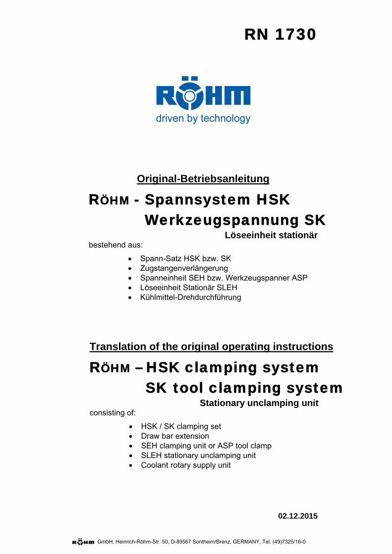
Original-Betriebsanleitung
RÖHM - Spannsystem HSK Werkzeugspannung SK
Löseeinheit stationär bestehend aus:
Spann-Satz HSK bzw. SK Zugstangenverlängerung Spanneinheit SEH bzw. Werkzeugspanner ASP Löseeinheit Stationär SLEH Kühlmittel-Drehdurchführung
02.12.2015
Translation of the original operating instructions
RÖHM – HSK clamping system SK tool clamping system
Stationary unclamping unit consisting of:
HSK / SK clamping set Draw bar extension SEH clamping unit or ASP tool clamp SLEH stationary unclamping unit Coolant rotary supply unit
******************************************************************************************** Seite: 2 **
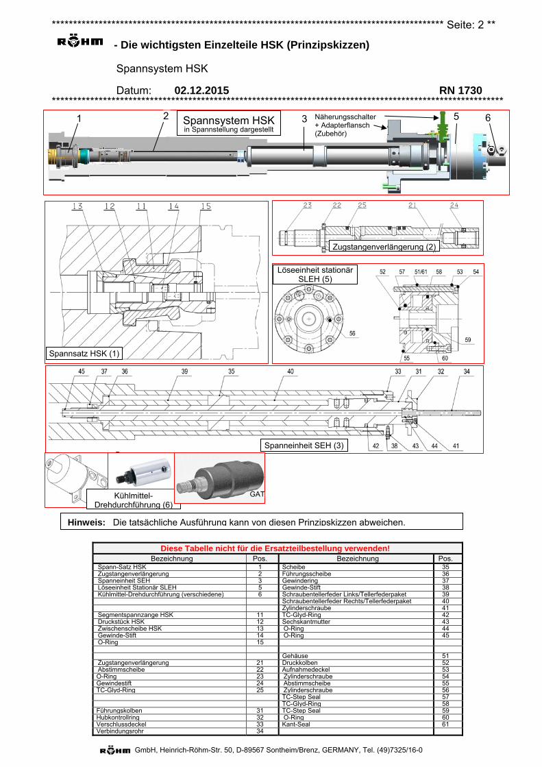
- Die wichtigsten Einzelteile HSK (Prinzipskizzen)
Spannsystem HSK
Datum: 02.12.2015 RN 1730 **********************************************************************************************************
GmbH, Heinrich-Röhm-Str. 50, D-89567 Sontheim/Brenz, GERMANY, Tel. (49)7325/16-0
Diese Tabelle nicht für die Ersatzteilbestellung verwenden! Bezeichnung Pos. Bezeichnung Pos.
Spann-Satz HSK 1 Scheibe 35 Zugstangenverlängerung 2 Führungsscheibe 36Spanneinheit SEH 3 Gewindering 37Löseeinheit Stationär SLEH 5 Gewinde-Stift 38 Kühlmittel-Drehdurchführung (verschiedene) 6 Schraubentellerfeder Links/Tellerfederpaket 39
Schraubentellerfeder Rechts/Tellerfederpaket 40Zylinderschraube 41
Segmentspannzange HSK 11 TC-Glyd-Ring 42Druckstück HSK 12 Sechskantmutter 43Zwischenscheibe HSK 13 O-Ring 44Gewinde-Stift 14 O-Ring 45O-Ring 15
Gehäuse 51Zugstangenverlängerung 21 Druckkolben 52Abstimmscheibe 22 Aufnahmedeckel 53O-Ring 23 Zylinderschraube 54Gewindestift 24 Abstimmscheibe 55TC-Glyd-Ring 25 Zylinderschraube 56
TC-Step Seal 57 TC-Glyd-Ring 58
Führungskolben 31 TC-Step Seal 59 Hubkontrollring 32 O-Ring 60Verschlussdeckel 33 Kant-Seal 61Verbindungsrohr 34
Spannsatz HSK (1)
Zugstangenverlängerung (2)
Spanneinheit SEH (3)
Hinweis: Die tatsächliche Ausführung kann von diesen Prinzipskizzen abweichen.
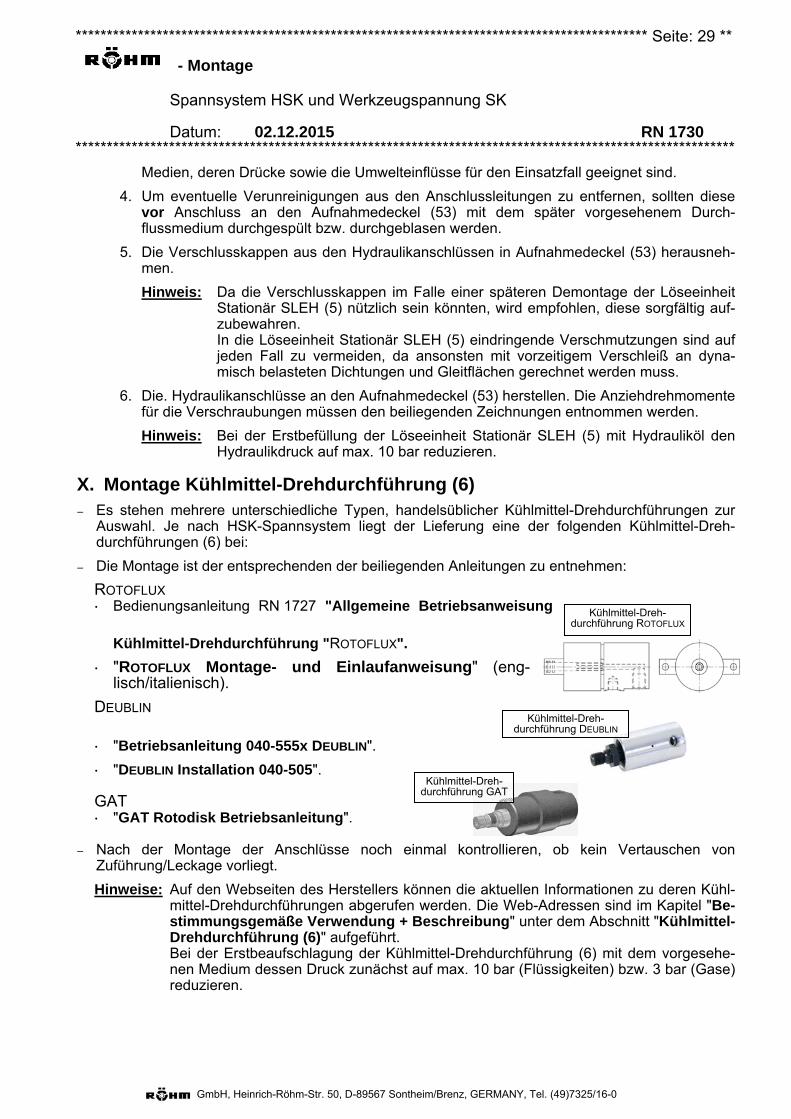
ROTOFLUX
DEUBLIN
Kühlmittel-Drehdurchführung (6)
GAT
Löseeinheit stationär SLEH (5)
Spannsystem HSK in Spannstellung dargestellt
5 6 3 2 1 Näherungsschalter+ Adapterflansch (Zubehör)
******************************************************************************************** Seite: 3 **
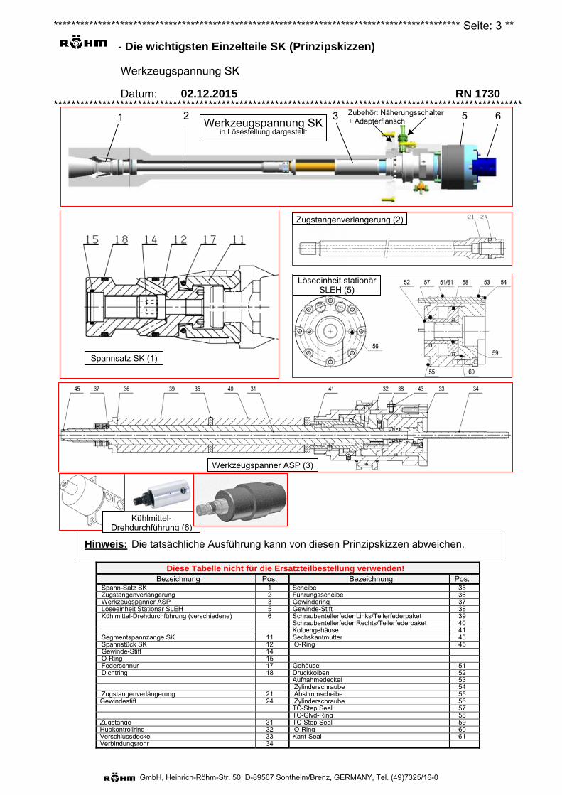
- Die wichtigsten Einzelteile SK (Prinzipskizzen)
Werkzeugspannung SK
Datum: 02.12.2015 RN 1730 **********************************************************************************************************
GmbH, Heinrich-Röhm-Str. 50, D-89567 Sontheim/Brenz, GERMANY, Tel. (49)7325/16-0
Diese Tabelle nicht für die Ersatzteilbestellung verwenden! Bezeichnung Pos. Bezeichnung Pos.
Spann-Satz SK 1 Scheibe 35 Zugstangenverlängerung 2 Führungsscheibe 36 Werkzeugspanner ASP 3 Gewindering 37 Löseeinheit Stationär SLEH 5 Gewinde-Stift 38 Kühlmittel-Drehdurchführung (verschiedene) 6 Schraubentellerfeder Links/Tellerfederpaket 39 Schraubentellerfeder Rechts/Tellerfederpaket 40 Kolbengehäuse 41 Segmentspannzange SK 11 Sechskantmutter 43 Spannstück SK 12 O-Ring 45 Gewinde-Stift 14 O-Ring 15 Federschnur 17 Gehäuse 51 Dichtring 18 Druckkolben 52 Aufnahmedeckel 53 Zylinderschraube 54 Zugstangenverlängerung 21 Abstimmscheibe 55 Gewindestift 24 Zylinderschraube 56 TC-Step Seal 57 TC-Glyd-Ring 58 Zugstange 31 TC-Step Seal 59 Hubkontrollring 32 O-Ring 60 Verschlussdeckel 33 Kant-Seal 61 Verbindungsrohr 34
Zubehör: Näherungsschalter + Adapterflansch
Hinweis: Die tatsächliche Ausführung kann von diesen Prinzipskizzen abweichen.
Kühlmittel-Drehdurchführung (6)
Löseeinheit stationär SLEH (5)
Spannsatz SK (1)
Zugstangenverlängerung (2)
Werkzeugspanner ASP (3)
Werkzeugspannung SK in Lösestellung dargestellt
5 6 3 2 1
******************************************************************************************** Seite: 4 **
- Begriffe
Spannsystem HSK und Werkzeugspannung SK
Datum: 02.12.2015 RN 1730 **********************************************************************************************************
GmbH, Heinrich-Röhm-Str. 50, D-89567 Sontheim/Brenz, GERMANY, Tel. (49)7325/16-0
Für die Anwendung dieses Dokuments gelten die folgenden Begriffe.
Betätigungskraft Kraft, welche in Spannstellung am Spannsatz HSK (1) bzw. an Druckstück HSK (12) oder am Spann-satz SK (1) bzw. an Spannstück SK (12) wirkt.
Einzugskraft (a) HSK: Mit "Einzugskraft" wird häufig die Spannkraft (siehe unten, genormter Begriff für Spann-
system HSK) bezeichnet, da dieser Ausdruck hervorragend die Kraftwirkung beschreibt.
(b) SK: Bei Werkzeugspannung SK: Kraft mit welcher das Steilkegel-Werkzeug an dessen Anzugsbolzen von der Segmentspannzange SK (11) axial in die Werkzeugspindel gezo-gen wird.
Federkraft Kraft, erzeugt von der Schraubentellerfeder Links/Tellerfederpaket (39) bzw. Schraubentellerfeder Rechts/Tellerfederpaket (40) und abgegeben wird bei Spannsystem
(a) HSK: an den Führungskolben (31).
(b) SK: über das Keilgetriebe von Werkzeugspanner ASP (3) an dessen Zugstange (31).
HSK Spannsystem für Werkzeuge mit Hohlschaftkegel DIN 69893-1:2011-04 und VDMA 34181:2005-07 zum Einbau in Werkzeugspindeln nach DIN 69063-1:2005-05.
Lösekraft Benötigte Kraft um die Spanneinheit SEH (3) bzw. den Werkzeugspanner ASP (3) sicher zu lösen und das Werkzeug aus der Werkzeugspindel auszustoßen.
Nenneinzugskraft Auch: Nennspannkraft. Spannkraft welche in neuem bzw. gut gewartetem Zustand des Spannsys-tems erreicht werden muss.
SK Spannsystem für Werkzeuge mit Steilkegel nach DIN ISO 7388-1 und Anzugsbolzen nach DIN ISO 7388-3 bzw. JIS B 6339 (für Werkzeugmaschinen im asiatischen Raum, früher MAS-BT) zum Einbau in Werkzeugspindeln entweder nach DIN 2079 oder nach ISO 9270-1 bzw. ISO 9270-2.
Spannkraft (nur HSK) Kraft gemäß Definition nach DIN 69063-1:2005-05, DIN 69893-1:2011-04 und VDMA 34181:2005-07, mit welcher das Hohlschaftkegel-Werkzeug von der Segmentspannzange HSK (11) axial in die Werkzeugspindel gezogen wird. In DIN 69893-1:2011-04 wird, abhängig von der Werkzeuggröße, eine Empfehlung der Höhe der Spannkraft angegeben.
Grenzbiegemoment (a) HSK: Das Biegemoment auf ein mit der empfohlenen Spannkraft gemäß DIN 69893-1:2011-04
gespanntes Werkzeug, bei dessen Überschreitung mit einem einseitigen Abheben des Werkzeugbundes von der Werkzeugspindel-Planfläche gerechnet werden muss.
(b) SK: Das Biegemoment auf ein mit mindestens der min. Spannkraft gemäß Tabelle "Grenz-werte SK-Spannsystem" (in Kapitel "Bestimmungsgemäße Verwendung + Beschrei-bung") gespanntes Werkzeug, bei dessen Überschreitung mit einem einseitigen Abhe-ben des Werkzeugbundes von der Werkzeugspindel-Planfläche gerechnet werden muss.
******************************************************************************************** Seite: 5 **
- Begriffe
Spannsystem HSK und Werkzeugspannung SK
Datum: 02.12.2015 RN 1730 **********************************************************************************************************
GmbH, Heinrich-Röhm-Str. 50, D-89567 Sontheim/Brenz, GERMANY, Tel. (49)7325/16-0
Grenzdrehmoment (a) HSK: Das Drehmoment auf ein mit der empfohlenen Spannkraft gemäß DIN 69893-1:2011-04
gespanntes Werkzeug, bei dessen Überschreitung mit einem Durchdrehen des Werk-zeugschaftes innerhalb der Werkzeugspindelbohrung gegen die wirkenden Reibkräfte ge-rechnet werden muss.
Wird z. B. bei einem Hohlschaftkegel Typ "A" oder "C" die Belastung des Mitnehmers (Nutstein) mit berücksichtig, ergibt sich ein erheblich vergrößertes Grenzdrehmoment.
(b) SK: Das Drehmoment auf ein mit mindestens der min. Spannkraft gemäß Tabelle "Grenzwer-te SK-Spannsystem" (in Kapitel "Bestimmungsgemäße Verwendung + Beschrei-bung") gespanntes Werkzeug, bei dessen Überschreitung mit einem Durchdrehen des Werkzeugschaftes innerhalb der Werkzeugspindelbohrung gegen die wirkenden Reibkräf-te gerechnet werden muss.
Verschleißgrenze (a) HSK: Die Verschleißgrenze (besser Spannkraft-Verschleißgrenze) wird dann überschritten,
wenn die gemessene Spannkraft die empfohlene Spannkraft gemäß DIN 69893-1:2011-04 unterschreitet.
(b) SK: Die Verschleißgrenze (besser Spannkraft-Verschleißgrenze) wird dann überschritten, wenn die gemessene Spannkraft die min. Spannkraft gemäß Tabelle "Grenzwerte SK-Spannsystem" (in Kapitel "Bestimmungsgemäße Verwendung + Beschreibung") un-terschreitet.
******************************************************************************************** Seite: 6 **
- Bestimmungsgemäße Verwendung + Beschreibung
Spannsystem HSK und Werkzeugspannung SK
Datum: 02.12.2015 RN 1730 **********************************************************************************************************
GmbH, Heinrich-Röhm-Str. 50, D-89567 Sontheim/Brenz, GERMANY, Tel. (49)7325/16-0
Vorbemerkung: 1. Diese Betriebsanleitung ist unter Berücksichtigung der DIN EN ISO 12100-1, DIN EN ISO 12100-2, DIN EN ISO 23125 und der dazugehörigen einschlägigen Normen erstellt.
2. Wenn im nachfolgenden Text Einzelteilnamen erwähnt werden, sowird auch immer in Klammern die Positions-Nummer aus denSkizzen in Kapitel "Die wichtigsten Einzelteile" ab Seite 2 ange-geben. Diese Positions-Nummern entsprechen grundsätzlich denin der Einzelteilliste in Kapitel "Die wichtigsten Einzelteile" ange-gebenen Nummern.
Baugruppen Spann-Satz HSK (1) bzw. Spann-Satz SK (1).
Zugstangenverlängerung (2).
Spanneinheit SEH (3) bzw. Werkzeugspanner ASP (3)
Löseeinheit Stationär SLEH (5).
Kühlmittel-Drehdurchführung (6).
Umgebungsbedingungen – Umgebungsbedingungen (in Anlehnung an die EN 60204):
• relative Luftfeuchte (bei 40°C) 50 %.
• Verschmutzung der Umgebung im Rahmen der von den Maschinen selbst ausgehenden Ver-schmutzung.
• Keine ionisierende und nicht ionisierende Strahlung.
• Nicht explosionsgefährdete Umgebung.
• Schwingungsfreier Untergrund/Befestigungen.
• Umgebungstemperatur am Einsatzort (Werkzeugspindelbohrung) 5°C bis 80°C. Höhere Umge-bungstemperaturen nur nach schriftlicher Zusage des Herstellers.
• Umgebungstemperatur bei Transport und Lagerung - 15°C bis 55°C (für 24 h auch bis 70°C).
Bestimmungsgemäße Verwendung Hinweis: Der Hersteller kann selbstverständlich keine Verantwortung für Personen- oder Sach-
schäden übernehmen, welche durch die nicht bestimmungsgemäße Verwendung dieses Produktes entstehen.
Speziell für Spannsystem HSK
– Die Innenkontur der Werkzeugspindel, in welche das Spannsystem HSK, insbesondere jedoch derSpann-Satz HSK (1) eingebaut und betrieben werden soll, muss dem Typ HSK DIN 69063-1 ent-sprechen.
– Mit dem Spannsystem HSK, insbesondere mit dem Spann-Satz HSK (1) dürfen ausschließlichWerkzeuge mit Schäften nach DIN 69893 gespannt werden.
– Werden Medien (z. B. Kühlmittel) durch das Spannsystem HSK durchgeführt, dann muss auch einWerkzeug mit einem unbeschädigten Abnahmerohr (z. B. Kühlmittelrohr) verwendet werden.Nichtbeachtung dieses Grundsatzes führt zur Verminderung der Spannkraft und damit zu einerVerringerung der übertragbaren Momente.
******************************************************************************************** Seite: 7 **
- Bestimmungsgemäße Verwendung + Beschreibung
Spannsystem HSK und Werkzeugspannung SK
Datum: 02.12.2015 RN 1730 **********************************************************************************************************
GmbH, Heinrich-Röhm-Str. 50, D-89567 Sontheim/Brenz, GERMANY, Tel. (49)7325/16-0
Speziell für Werkzeugspannung SK
– Die Innenkontur der Werkzeugspindel, in welche die Werkzeugspannung, insbesondere jedoch derSpann-Satz SK (1) eingebaut und betrieben werden soll, muss entweder der DIN 2079 oder derISO 9270-1 bzw. ISO 9270-2 entsprechen.
– Mit dieser Werkzeugspannung, insbesondere mit dem Spann-Satz SK (1) dürfen ausschließlichWerkzeuge mit Schaft nach DIN ISO 7388-1 und mit Anzugsbolzen nach DIN ISO 7388-3 bzw. JISB 6339 (früher MAS-BT, für Werkzeugmaschinen aus dem asiatischen Raum) gespannt werden.
Allgemein für HSK/SK
– Nur für den gewerblichen Gebrauch bestimmt.
– Nur wenn eine schriftliche Zustimmung des Herstellers vorliegt, darf das Spannsystem HSK / dieWerkzeugspannung SK
• in von o. g. Normen abweichende Werkzeugspindeln eingebaut werden.
• zur Spannung von Werkzeugen verwendet werden, deren Schäfte und/oder Anzugsbolzen vono. g. Normen abweichen.
– Das Spannsystem HSK / die Werkzeugspannung SK ist nach dem Stand der Technik konstruiertund hergestellt. Alle einschlägigen Sicherheitsbestimmungen wurden beachtet. Dennoch sind auchbei bestimmungsgemäßer Verwendung des Spannsystems Restgefahren vorhanden.
– Das Spannsystem HSK / die Werkzeugspannung SK ist zum An- und Einbau in Werkzeugspindelnvorgesehen.
– Das Werkzeug darf nur bei Stillstand der Werkzeugspindel gespannt bzw. hydraulisch oder pneu-matisch gelöst werden.
– Alle Zylinderschrauben (54) der Löseeinheit Stationär SLEH (5) müssen mit dem vorgeschriebe-nen Anziehdrehmoment festgezogen werden.
– In gespanntem Zustand von Spannsystem HSK / Werkzeugspannung SK muss die LöseeinheitStationär SEH (5) aktiv von der Spanneinheit SEH (3) bzw. von dem Werkzeugspanner ASP (3)abgehoben sein.
– Das Einstellmaß in Lösestellung muss entsprechend der Angaben in Kapitel "Instandhaltung"regelmäßig überprüft und - wenn erforderlich - nachjustiert werden.
– Die in den technischen Daten (siehe zugehörige Zeichnung(en) im Anhang) angegebenen Grenz-werte (z. B. Spindeldrehzahl, Betätigungsdrücke usw.) dürfen nicht überschritten werden.
– Die Maschine, in die das Spannsystem HSK / die Werkzeugspannung SK eingebaut ist, darf nurmit Kühlschmierstoffen auf Wasserbasis mit einem Ölanteil < 15 % betrieben werden.
– Bei Verwendung eines Kühlschmierstoffes auf Wasserbasis mit einem Ölanteil größer 15 % undbei nicht wassermischbaren Kühlschmierstoffen müssen entsprechende Schutzmaßnahmen ergrif-fen werden (z. B. Brandschutzeinheit).
– Bei Einsatz eines Minimalmengenschmiersystems oder bei Trockenbearbeitung muss mit nachtei-ligen Einwirkungen auf die Standzeit der Komponenten des Spannsystems und, unter ungünstigenUmständen, auf die Maschinensicherheit gerechnet werden. Deshalb darf der Einsatz eines sol-chen Systems nur nach Rücksprache mit dem Hersteller erfolgen. Dabei muss geprüft werden,welche weiteren Einheiten für einen sicheren Betrieb der Maschine erforderlich sind.
– Weder das zulässige Grenzbiegemoment noch das zulässige Grenzdrehmoment auf das einge-setzte Werkzeug darf überschritten werden. Siehe dazu unten "Technische Daten" -> "Grenzwer-te" bzw. die Angaben auf der zugehörigen Zusammenstellungszeichnung im Anhang.
– Gasförmige oder flüssige Medien dürfen zentral durch das Spannsystem HSK / die Werkzeug-spannung SK durchgeführt werden. Maßgeblich für die Höhe des zulässigen Mediendruckes, dieArt der zulässigen Medien und die mindest erforderliche Filterfeinheit ist in der Regel die verwen-dete Kühlmittel-Drehdurchführung (6). Siehe dazu deren Betriebsanleitung.
******************************************************************************************** Seite: 8 **
- Bestimmungsgemäße Verwendung + Beschreibung
Spannsystem HSK und Werkzeugspannung SK
Datum: 02.12.2015 RN 1730 **********************************************************************************************************
GmbH, Heinrich-Röhm-Str. 50, D-89567 Sontheim/Brenz, GERMANY, Tel. (49)7325/16-0
– Gehört keine Kühlmittel-Drehdurchführung (6) zum Umfang des Spann-Systems, dann gelten fol-gende Mindestanforderungen für die durchgeleiteten Medien:
• max. zul. Mediendruck 60 bar.
• keine brennbare, explosive, korrosive oder ätzende Flüssigkeiten oder Gase.
• Filterfeinheit max. 60 μm.
– Während des Werkzeugwechsels kann - je nach verwendeter Drehdurchführung (6) - optional aufein anderes Medium (z. B. Druckluft für die Kegelreinigung) umgeschaltet werden.
– Um einem vorzeitigen Verschleiß und daraus resultierendem Verlust der Spannkraft vorzubeugen,müssen die Filterfeinheiten von ausgewählten Medien, angegeben unten unter Punkt "Merkmale",eingehalten werden.
Bestimmungswidrige Verwendung / naheliegender Missbrauch Speziell für Spannsystem HSK
– Wird das Spannsystem HSK mit einem Werkzeug ohne Abnahmerohr (z. B. Kühlmittelrohr) be-trieben, darf kein Medium (z. B. Kühlmittel) durchgeführt werden.
Allgemein für HSK/SK
– Das Spannsystem HSK / die Werkzeugspannung SK darf nicht als Lastaufnahmemittel (z. B. alsGreifer) verwendet werden.
– Das Spannsystem HSK und insbesondere die Spanneinheit SEH (3) bzw. die Werkzeug-spannung SK und insbesondere der Werkzeugspanner ASP (3) darf nicht zerlegt werden.
– Ein Wechseln des Werkzeugs bzw. Lösen von Spannsystem HSK / Werkzeugspannung SKwährend des umlaufenden Betriebes der Werkzeugspindel ist strengstens verboten.
– Ohne eingesetztes Werkzeug darf das Spannsystem HSK / die Werkzeugspannung SK nichtmit Drehzahlen über 500 min-1 betrieben werden!
– Die Anschlüsse "Spannen" und "Lösen" der Löseeinheit Stationär SLEH (5) dürfen nicht ver-tauscht werden
– Der Anschluss "Spannen" der Löseeinheit Stationär SLEH (5) darf während des umlaufenden Be-triebes der Werkzeugspindel niemals drucklos sein.
– Ohne korrekt angebaute, justierte und betriebsbereite Hubabfragesensoren (z. B. Näherungs-schalter) darf das Spannsystem HSK / die Werkzeugspannung SK nicht betrieben werden.
– Die Form und Masse des Werkzeuges ist von großer Bedeutung. Deshalb gilt:
• Die Werkzeuge müssen eine ausgeglichene Masse besitzen.
• Wenn keine ausgeglichene Masse möglich ist, muss bei unwuchtigen Werkzeugen die Dreh-zahl auf einen unkritischen Wert reduziert werden.
• Es dürfen nur vom Hersteller zugelassene Spannsysteme mit entsprechenden Einzelkompo-nenten, z. B. einem Spann-Satz, verwendet werden.
• Das Spannsystem HSK / die Werkzeugspannung SK muss entsprechend der Angaben in derBenutzerdokumentation und geltenden Richtlinien ausgelegt und verwendet werden.
– Die verwendeten Werkzeuge dürfen nicht fehlerhaft oder beschädigt sein.
– Die Zuführung der Werkzeuge darf nicht ungenau erfolgen. Eine Kollision mit dem SpannsystemHSK / die Werkzeugspannung SK ist unbedingt zu vermeiden.
– Eine Überlastung von Spannsystem HSK / Werkzeugspannung SK hinsichtlich Drehzahl, Biege- oder Drehmoment führt zum Bruch von Bauteilen und damit zur Beschädigung oder zum Ausfallvon Spannsystem HSK / Werkzeugspannung SK.
– Während des regulären Betriebes darf kein manueller Werkzeugwechsel, ggf. sogar unter Druck-
******************************************************************************************** Seite: 9 **
- Bestimmungsgemäße Verwendung + Beschreibung
Spannsystem HSK und Werkzeugspannung SK
Datum: 02.12.2015 RN 1730 **********************************************************************************************************
GmbH, Heinrich-Röhm-Str. 50, D-89567 Sontheim/Brenz, GERMANY, Tel. (49)7325/16-0
beaufschlagung der Kegelreinigungs- bzw. Blasluft, vorgenommen werden. Ausnahme: Einrichte-betrieb.
– Die Verwendung unzulässiger oder unreiner Medien kann zu erhöhtem Verschleiß und daraus resultierendem Verlust der Spann- bzw. Einzugskraft führen.
– Die Kühlmittel-Drehdurchführung (6) ist eine komplette Einheit und darf nicht geöffnet oder geän-dert werden.
– Die Anschlüsse "Zuführung" und "Leckage" an die Kühlmittel-Drehdurchführung (6) dürfen nicht vertauscht oder fehlerhaft montiert werden.
– Die Verwendung von Druckluft von außen zur allgemeinen Reinigung von Spannsystem HSK / Werkzeugspannung SK ist nicht zulässig.
– Die durchgeführten Medien dürfen nicht korrosiv sein.
Pflichten des Betreibers – Um eine unzureichende oder mangelhafte Werkzeugspannung rechtzeitig erkennen zu können,
muss die korrekte axiale Position von Druckstück HSK (12) kontrolliert werden. Dazu muss das Spannsystem HSK / die Werkzeugspannung SK mit einer Hubkontrolleinrichtung überwacht werden.
– Um ein Lösen des Spannsystems unter Rotation der Werkzeugspindel ausschließen zu kön-nen, muss die Maschinensteuerung entsprechend programmiert werden.
– Um den Bediener vor herausschleudernden Teilen zu schützen, muss nach DIN EN ISO 23125:2012-07 an der Werkzeugmaschine eine trennende Schutzeinrichtung vorhanden sein.
– Die Temperatur der Maschinenspindelbohrung muss überwacht werden. Die Schraubentellerfeder Links/Tellerfederpaket (39) und Schraubentellerfeder Rechts/Tellerfederpaket (40) dürfen keiner Dauerbetriebstemperatur über 80°C ausgesetzt wer-den, da ansonsten mit einer vorzeitigen Ermüdung der Federkräfte und damit erheblich nachlas-senden Spann- oder Einzugskräften gerechnet werden muss.
– Bei Stillstand der Werkzeugspindel muss die Zuleitung an die Kühlmittel-Drehdurchführung (6) drucklos geschaltet werden.
– Die angegebenen technischen Daten des Spannsystems hinsichtlich Drehzahl, Biege- oder Dreh-moment dürfen nicht überschritten werden.
– Vor allen Arbeiten an den Einzelteilen des Spannsystems ist sicherzustellen, dass:
• die entsprechenden Teile der Benutzerdokumentation dem zuständigen Personal zur Verfü-gung stehen.
• die Benutzerdokumentation und Hinweisschilder an der Maschine und an der Spanneinrichtung vom zuständigen Personal gelesen und verstanden wurden. Dies gilt besonders für alle Sicher-heits- und Warnhinweise.
• das zuständige Personal, entsprechend seiner Tätigkeit, ausreichend qualifiziert ist. Dies gilt besonders für die Inbetriebnahme, Wartung/Instandhaltung und Reparatur, sowie für alle Arbei-ten an elektrischen Anlagen und Bauteilen. Einschlägige Vorschriften und Richtlinien sowie die Benutzerdokumentation müssen beachtet werden.
• alle Sicherheitseinrichtungen ordnungsgemäß angebracht und funktionsfähig sind. Sicherheits-einrichtungen dürfen nicht manipuliert oder außer Kraft gesetzt werden. Die Widerstandsklas-sen der trennenden Schutzeinrichtungen (z. B. Schutzhauben, Sicherheitsfenster) müssen be-achtet werden.
• die Maschine und das Spannsystem HSK / die Werkzeugspannung SK sich in technisch ein-wandfreiem Zustand befinden.
• alle beschädigten oder defekten Teile umgehend erneuert werden. Dies gilt besonders für alle Sicherheitseinrichtungen.
******************************************************************************************** Seite: 10 **
- Bestimmungsgemäße Verwendung + Beschreibung
Spannsystem HSK und Werkzeugspannung SK
Datum: 02.12.2015 RN 1730 **********************************************************************************************************
GmbH, Heinrich-Röhm-Str. 50, D-89567 Sontheim/Brenz, GERMANY, Tel. (49)7325/16-0
– Veränderungen an dem Spannsystem HSK / der Werkzeugspannung SK sind generell mit einem Sicherheitsrisiko verbunden. Deshalb gilt:
• Veränderungen an dem Spannsystem HSK / der Werkzeugspannung SK dürfen nur mit schrift-licher Genehmigung des Herstellers vorgenommen werden. Dies gilt besonders für alle Sicher-heitseinrichtungen, elektrischen Schaltungen und die Software der Maschinensteuerung.
• Alle Veränderungen müssen nachvollziehbar dokumentiert werden.
– Die Verwendung von Originalteilen ist von entscheidender Bedeutung für die Sicherheit des Spannsystems. Deshalb gilt:
• Ersatzteile, Zusatzeinrichtungen, Baugruppen oder sonstiges Zubehör von Fremdherstellern müssen vom Hersteller zugelassen werden.
• Die Dokumentation des Fremdherstellers muss beachtet werden.
– Kollisionen gilt es zu vermeiden. Den Bewegungsablauf auf mögliche Kollision hin überprüfen. Kommt es dennoch zu einer Kollision, muss das Spannsystem HSK / die Werkzeugspannung SK gemäß den Angaben in der Benutzerdokumentation überprüft werden.
– Angaben zu Hilfs-, Kühl- und Schmierstoffen, sowie für Angaben zur Wartung/Instandhaltung des Spannsystems müssen beachtet werden. Bei Transport, Wartung/Instandhaltung und Reparatur müssen evtl. benötigte, zusätzliche Sicherheitseinrichtungen verwendet werden.
– Bei der Entsorgung des Spannsystems bzw. von Hilfs-, Kühl- und Schmierstoffen müssen die ein-schlägigen Vorschriften und Richtlinien beachtet werden.
– Starke Hitzeentwicklung, offenes Feuer oder sonstige Zündquellen (z. B. Zigaretten) im Umge-bungsbereich des Spannsystems sind verboten.
– Die Vermeidung von Bränden/Explosionen obliegt dem Betreiber. Die erforderlichen Maßnahmen müssen in Zusammenarbeit mit den erforderlichen Institutionen (z. B. Brandschutzbeauftragter, Feuerversicherer, Feuerwehr) festgelegt werden. Dies gilt besonders für Maschinen, die in der Regel unbeaufsichtigt betrieben werden.
Persönliche Schutzausrüstung – Die Bereitstellung der persönlichen Schutzausrüstung muss der Betreiber der Maschine sicherstel-
len. Die Verwendung von persönlicher Schutzausrüstung steht in engem Zusammenhang mit dem Fertigungsprozess. Verwendung von persönlicher Schutzausrüstung mit dem Sicherheitsbeauf-tragten klären.
– Persönliche Schutzausrüstung, die gegebenenfalls erforderlich ist:
• Gehörschutz
• Augenschutz (Schutzbrille)
• Handschutz (Handschuhe)
• Fußschutz (Sicherheitsschuhe)
• Kopfschutz (Schutzhelm)
• Eng anliegende, schwer entflammbare Arbeitskleidung
• Haarnetz
• Hautschutzmittel.
Außerbetriebnahme / Stillsetzen – Das Spannsystem muss außer Betrieb genommen bzw. stillgesetzt werden
• nach Ablauf der auf der Zusammenstellungszeichnung angegebenen Lebensdauer. Soll das Spannsystem über die angegebene Lebensdauer hinaus betrieben oder nach erfolgter Stillsetzung wieder in Betrieb genommen werden, so muss dieses zuvor vom Hersteller gene-
******************************************************************************************** Seite: 11 **
- Bestimmungsgemäße Verwendung + Beschreibung
Spannsystem HSK und Werkzeugspannung SK
Datum: 02.12.2015 RN 1730 **********************************************************************************************************
GmbH, Heinrich-Röhm-Str. 50, D-89567 Sontheim/Brenz, GERMANY, Tel. (49)7325/16-0
ralüberholt werden bzw. sind die in Kapitel "Instandhaltung" aufgeführten Inspektionsmaß-nahmen durchzuführen.
• wenn die in Kapitel "Instandhaltung" aufgeführten Messwerte bei den Inspektionsmaßnahmen nicht mehr erreicht werden können. Ein Weiterbetrieb ist nur dann zulässig, wenn aufgrund nachlassender Spannkraft auch nur ein entsprechend reduziertes Grenzbiegemoment bzw. Grenzdrehmoment auf das eingesetzte Werkzeug wirkt. Siehe dazu unten "Technische Daten" -> "Grenzwerte" bzw. die Angaben auf der zugehörigen Zusammenstellungszeichnung im Anhang.
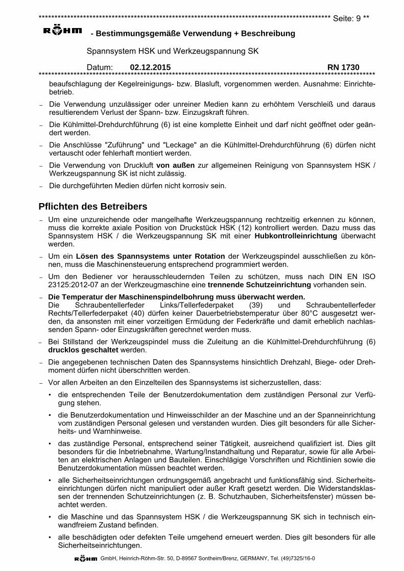
Merkmale Spann-Satz HSK (1)
– Mit dem Spann-Satz HSK (1) (Grafik siehe unten) können Hohlschaftkegelwerkzeuge nach DIN 69893 gespannt werden. Voraussetzung ist allerdings, dass die Bohrung der Werkzeugspindel, in welche das Spannsystem bzw. der Spann-Satz HSK (1) eingebaut und betrieben werden soll, der DIN 69063 sowie darüber hinausgehenden Vorgaben des Spannsystem-Herstellers entspricht.
– Die passende Größe kann der zugehörigen Zeichnung (siehe Anhang) entnommen werden.
– Der Spann-Satz HSK (1) greift mit der Segmentspannzange HSK (11) das Hohlschaftkegelwerkzeug, zieht dieses in die Hohl-schaftkegelbohrung der Werkzeugspindel und überträgt an-schließend die Axial- bzw. Spannkraft.
– Die Oberfläche an Druckstück HSK (12) ist mit einer Verschleiß-schutzschicht "DLC" überzogen. Siehe auch "DLC-Beschichtung".
– Der Spann-Satz HSK (1) besteht im Prinzip aus Segmentspannzange HSK (11), Druckstück HSK (12) Zwischenscheibe (13) Gewinde-Stift (14) und O-Ring (15).
– Wird der Spann-Satz HSK (1) geöffnet, dann gibt zunächst dessen Segmentspannzange HSK (11) das Hohlschaftkegelwerkzeug frei, welches anschließend über das Druckstück HSK (12) ausge-stoßen wird. Wichtig: Hohlschaftkegelwerkzeug extern halten!
– Durch Anpassen der Dicke von Abstimmscheibe (22) der Zugstangenverlängerung (2) (bzw. durch Einlegen einer zusätzlichen Passscheibe) kann das Einstellmaß bzw. Kontrollmaß von Druckstück HSK (12) in Lösestellung abgestimmt werden. Siehe Teil-Ansicht "Lösestellung".
– Technische Daten HSK:
Größe A25/B32 A32/B40 A40/B50 A50/B63 A63/B80 A80/B100 A100/B125
Betätigungskraft [kN] 0,7 1 2 3 4 7,5 10 Spannkraft [kN] 3,5 5 10 15 25 37,5 50 Gesamthub [mm] 7 9 13 15 14 17 18 Spannhub [mm] 4 5,5 7 8 8 11 12 Ausstoßhub [mm] 0,2 0,3 0,5 0,5 0,5 0,5 0,8 Gesamtlänge [mm] 28,8 35,1 42,5 50 62 80 98,5
– Siehe auch die "Allgemeine Betriebsanleitung für HSK-Spannsätze". Diese wird auf Anforde-rung zur Verfügung gestellt (in den Sprachen "deutsch" und "englisch" grundsätzlich kostenlos, weitere Sprachen auf Anfrage1).
1 Auf Anforderung in den Sprachen deutsch, englisch, italienisch, chinesisch und spanisch (Stand zum Erstellungsdatum) kostenfrei erhält-lich.
Spann-Satz HSK Spann-Satz HSK
Werkzeug mit Hohlschaftkegel Arbeitsspindel
Spannstellung
Lösestellung
Einstellmaß
Ausstoßhub
******************************************************************************************** Seite: 12 **
- Bestimmungsgemäße Verwendung + Beschreibung
Spannsystem HSK und Werkzeugspannung SK
Datum: 02.12.2015 RN 1730 **********************************************************************************************************
GmbH, Heinrich-Röhm-Str. 50, D-89567 Sontheim/Brenz, GERMANY, Tel. (49)7325/16-0
Wichtig: Bricht ein Teil der Segmentspannzange HSK (11), dann darf das Spannsystem HSK erst nach dem Austausch des gesamten Spann-Satz HSK (1) weiterbetrieben werden.
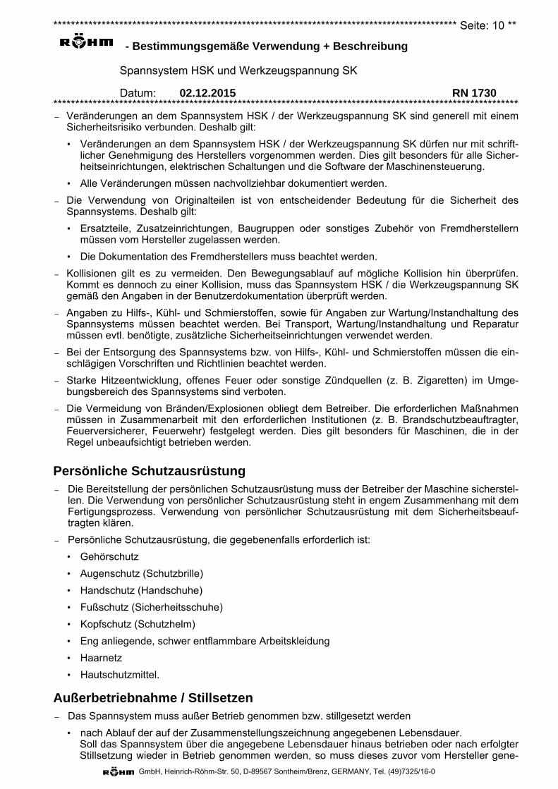
Spann-Satz SK (1)
– Mit dem Spann-Satz SK (1) (Grafik siehe unten) können Steilkegelwerkzeuge nach DIN 69871bzw. ISO 7388-1 mit Anzugsbolzen nach. DIN ISO 7388-3 (früher DIN 69872) und MAS BT ge-spannt werden. Voraussetzung ist allerdings, dass die Bohrung der Werkzeugspindel, in welchedas Spannsystem bzw. der Spann-Satz SK (1) eingebaut und betrieben werden soll, der DIN 2079sowie darüber hinausgehenden Vorgaben des Spannsystem-Herstellers entspricht.
– Die passende Größe kann der zugehörigen Zeichnung (siehe Anhang) entnommen werden.
– Der Spann-Satz SK (1) greift mit der Segmentspannzange SK (11) das Steilkegelwerkzeug, ziehtdieses in die Steilkegelbohrung der Werkzeugspindel und überträgt anschließend die Axial- bzw.Einzugskraft.
– Die Oberflächen an Segmentspannzange SK (11), welche mitdem Werkzeugzapfen bzw. mit der Werkzeugspindelbohrung inKontakt kommen, sind nach einem speziellen Verfahren laserge-härtet.
– Der Spann-Satz SK (1) besteht im Prinzip aus Segmentspannzange SK (11), Spannstück SK (12) O-Ring (15). Gewinde-Stift (14) Federschnur (17) und Dichtring (18)
– Wird der Spann-Satz SK (1) geöffnet, dann gibt zunächst dessen Segmentspannzange SK (11)den Anzugsbolzen des Steilkegelwerkzeugs frei, welches anschließend über das Spannstück SK(12) ausgestoßen wird. Wichtig: Steilkegelwerkzeug extern halten!
– Durch Anpassen der Einschraubtiefe der Zugstangenverlängerung (21) von Zugstangenverlän-gerung (2) in das Spannstück SK (12) von Spann-Satz SK (1) mit anschließendem Kontern durchdessen Gewinde-Stift (14) kann das Einstellmaß bzw. Kontrollmaß von Spannstück SK (12) in Lö-sestellung abgestimmt werden.
– Technische Daten SK:
Größe 30 40 45 50 60
Betätigungskraft [kN] 6 12 15 25 65Einzugskraft [kN] 6 12 15 25 65Gesamthub [mm] 5,8 6,0 6,2 6,2 9,5Spannhub [mm] 5,4 5,5 5,6 5,6 8,5Ausstoßhub [mm] 0,95 0,7 1,5 0,7 1,15
Wichtig: Bricht ein Teil der Segmentspannzange SK (11), dann darf die Werkzeugspannung SK erst nach dem Austausch des gesamten Spann-Satz SK (1) weiterbetrieben werden.
Zugstangenverlängerung (2)
– Die Zugstangenverlängerung (2) ist die mechani-sche Verbindung zwischen System HSK: dem Führungskolben (31) von
Spanneinheit SEH (3) und dem Druckstück HSK
Zugstangenver-längerung (2)
HSK
Spann-Satz SK
Werkzeug mit Steilkegel Arbeitsspindel
Spannstellung Lösestellung
******************************************************************************************** Seite: 13 **
- Bestimmungsgemäße Verwendung + Beschreibung
Spannsystem HSK und Werkzeugspannung SK
Datum: 02.12.2015 RN 1730 **********************************************************************************************************
GmbH, Heinrich-Röhm-Str. 50, D-89567 Sontheim/Brenz, GERMANY, Tel. (49)7325/16-0
(12) von Spann-Satz HSK (1).
bzw.
System SK: der Zugstange (31) von Werkzeug-spanner (3) und dem Spannstück SK (12) vonSpann-Satz SK (1)
– Sie dient der Übertragung von Kräften und Hüben sowie der Längenanpassung an die vorgegebe-ne, individuelle Werkzeugspindellänge.
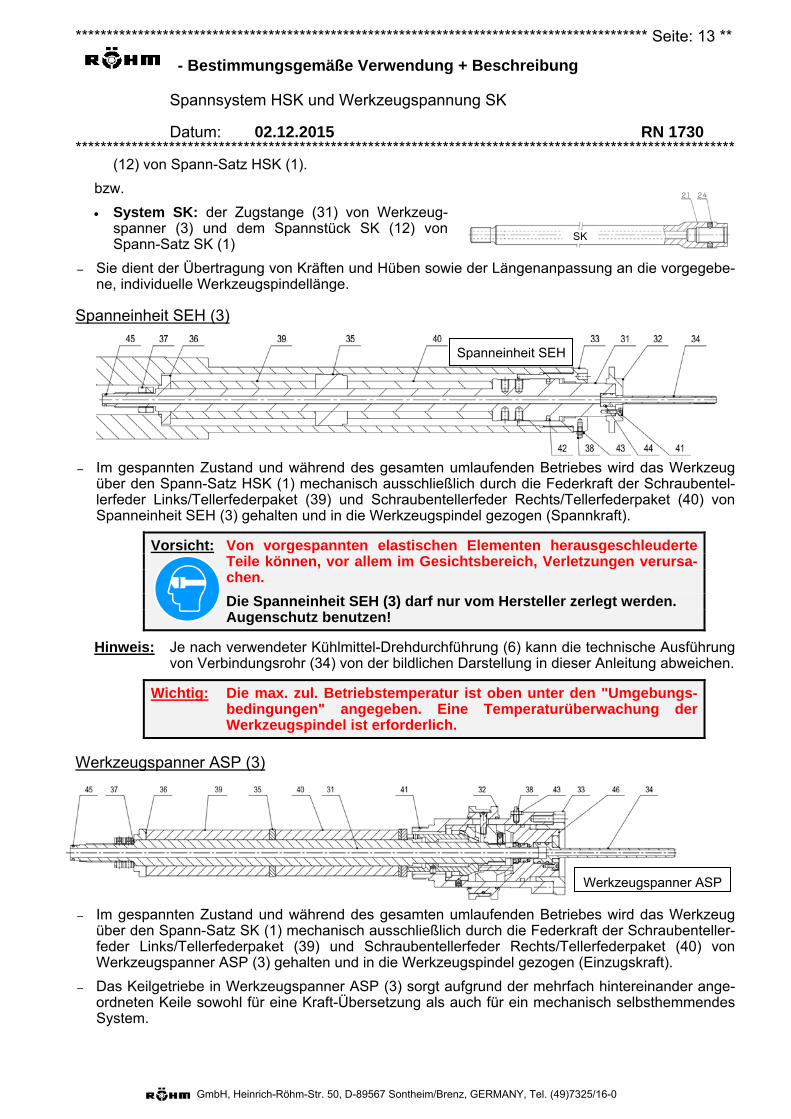
Spanneinheit SEH (3)
– Im gespannten Zustand und während des gesamten umlaufenden Betriebes wird das Werkzeugüber den Spann-Satz HSK (1) mechanisch ausschließlich durch die Federkraft der Schraubentel-lerfeder Links/Tellerfederpaket (39) und Schraubentellerfeder Rechts/Tellerfederpaket (40) vonSpanneinheit SEH (3) gehalten und in die Werkzeugspindel gezogen (Spannkraft).
Vorsicht: Von vorgespannten elastischen Elementen herausgeschleuderte Teile können, vor allem im Gesichtsbereich, Verletzungen verursa-chen.
Die Spanneinheit SEH (3) darf nur vom Hersteller zerlegt werden. Augenschutz benutzen!
Hinweis: Je nach verwendeter Kühlmittel-Drehdurchführung (6) kann die technische Ausführung von Verbindungsrohr (34) von der bildlichen Darstellung in dieser Anleitung abweichen.
Wichtig: Die max. zul. Betriebstemperatur ist oben unter den "Umgebungs-bedingungen" angegeben. Eine Temperaturüberwachung der Werkzeugspindel ist erforderlich.
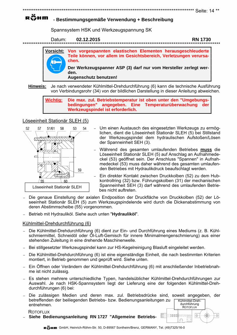
Werkzeugspanner ASP (3)
– Im gespannten Zustand und während des gesamten umlaufenden Betriebes wird das Werkzeugüber den Spann-Satz SK (1) mechanisch ausschließlich durch die Federkraft der Schraubenteller-feder Links/Tellerfederpaket (39) und Schraubentellerfeder Rechts/Tellerfederpaket (40) vonWerkzeugspanner ASP (3) gehalten und in die Werkzeugspindel gezogen (Einzugskraft).
– Das Keilgetriebe in Werkzeugspanner ASP (3) sorgt aufgrund der mehrfach hintereinander ange-ordneten Keile sowohl für eine Kraft-Übersetzung als auch für ein mechanisch selbsthemmendesSystem.
Spanneinheit SEH
SK
Werkzeugspanner ASP S
******************************************************************************************** Seite: 14 **
- Bestimmungsgemäße Verwendung + Beschreibung
Spannsystem HSK und Werkzeugspannung SK
Datum: 02.12.2015 RN 1730 **********************************************************************************************************
GmbH, Heinrich-Röhm-Str. 50, D-89567 Sontheim/Brenz, GERMANY, Tel. (49)7325/16-0
Löseeinheit Stationär SLEH
Vorsicht: Von vorgespannten elastischen Elementen herausgeschleuderte Teile können, vor allem im Gesichtsbereich, Verletzungen verursa-chen.
Der Werkzeugspanner ASP (3) darf nur vom Hersteller zerlegt wer-den. Augenschutz benutzen!
Hinweis: Je nach verwendeter Kühlmittel-Drehdurchführung (6) kann die technische Ausführung von Verbindungsrohr (34) von der bildlichen Darstellung in dieser Anleitung abweichen.
Wichtig: Die max. zul. Betriebstemperatur ist oben unter den "Umgebungs-bedingungen" angegeben. Eine Temperaturüberwachung der Werkzeugspindel ist erforderlich.
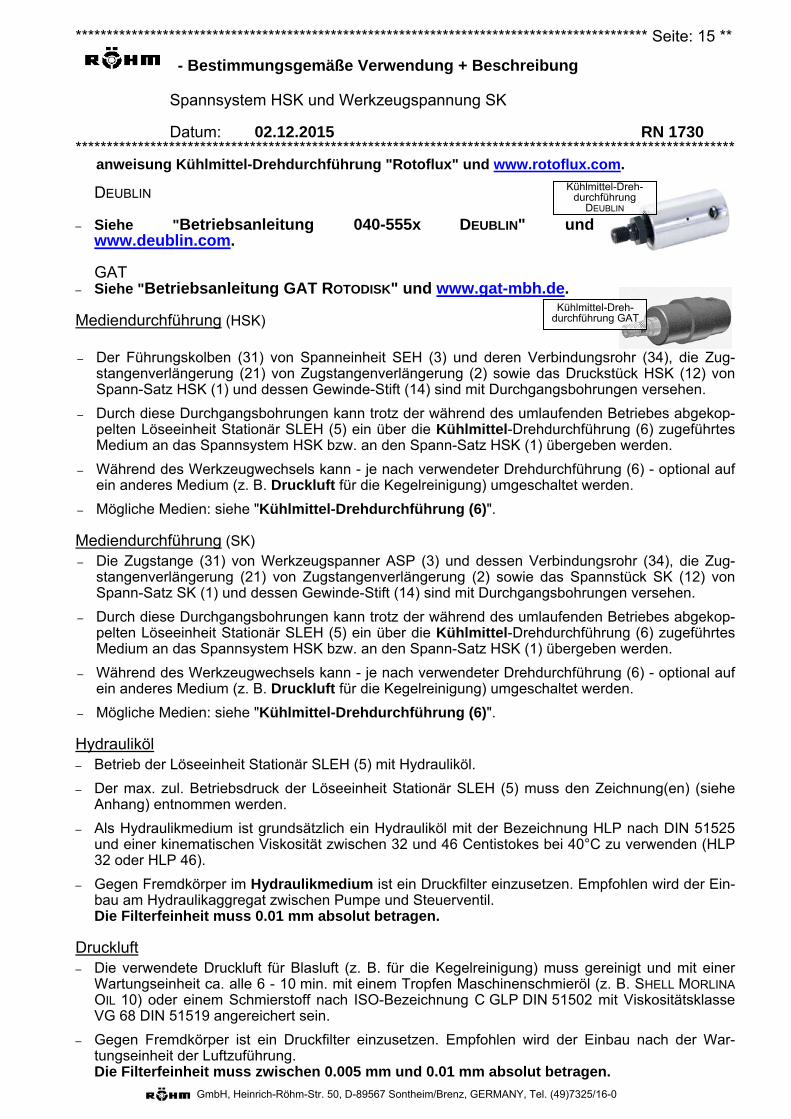
Löseeinheit Stationär SLEH (5)
– Um einen Austausch des eingesetzten Werkzeugs zu ermög-lichen, dient die Löseeinheit Stationär SLEH (5) bei Stillstandder Werkzeugspindel dem hydraulischen Aufstoßen/Lösender Spanneinheit SEH (3).
– Während des gesamten umlaufenden Betriebes muss dieLöseeinheit Stationär SLEH (5) auf Anschlag an Aufnahmede-ckel (53) geöffnet sein. Der Anschluss "Spannen" in Aufnah-medeckel (53) muss daher während des gesamten umlaufen-den Betriebes mit Hydraulikdruck beaufschlagt werden.
– Ein direkter Kontakt zwischen Druckkolben (52) zu dem Hub-kontrollring (32) bzw. Führungskolben (31) der mechanischenSpanneinheit SEH (3) darf während des umlaufenden Betrie-bes nicht auftreten.
– Die genaue Einstellung der axialen Endposition der Druckfläche von Druckkolben (52) der Lö-seeinheit Stationär SLEH (5) zum Werkzeugspindelende wird durch die Dickenabstimmung vonderen Abstimmscheibe (55) vorgenommen.
– Betrieb mit Hydrauliköl. Siehe auch unten "Hydrauliköl".
Kühlmittel-Drehdurchführung (6)
– Die Kühlmittel-Drehdurchführung (6) dient zur Ein- und Durchführung eines Mediums (z. B. Kühl-schmiermittel, Schneidöl oder Öl-Luft-Gemisch für innere Minimalmengenschmierung) aus einerstehenden Zuleitung in eine drehende Maschinenwelle.
– Bei stillgesetzter Werkzeugspindel kann zur HS-Kegelreinigung Blasluft eingeleitet werden.
– Die Kühlmittel-Drehdurchführung (6) ist eine eigenständige Einheit, die nach bestimmten Kriterienmontiert, in Betrieb genommen und geprüft wird. Siehe unten.
– Ein Öffnen oder Verändern der Kühlmittel-Drehdurchführung (6) mit anschließender Inbetriebnah-me ist nicht zulässig.
– Es stehen mehrere unterschiedliche Typen, handelsüblicher Kühlmittel-Drehdurchführungen zurAuswahl. Je nach HSK-Spannsystem liegt der Lieferung eine der folgenden Kühlmittel-Dreh-durchführungen (6) bei:
– Die zulässigen Medien und deren max. zul. Betriebsdrücke sind, soweit angegeben, derbetreffenden der beiliegenden Betriebs- bzw. Bedienungsanleitungen zu entnehmen.
ROTOFLUX – Siehe Bedienungsanleitung RN 1727 "Allgemeine Betriebs-
Kühlmittel-Dreh-durchführung
ROTOFLUX
******************************************************************************************** Seite: 15 **
- Bestimmungsgemäße Verwendung + Beschreibung
Spannsystem HSK und Werkzeugspannung SK
Datum: 02.12.2015 RN 1730 **********************************************************************************************************
GmbH, Heinrich-Röhm-Str. 50, D-89567 Sontheim/Brenz, GERMANY, Tel. (49)7325/16-0
anweisung Kühlmittel-Drehdurchführung "Rotoflux" und www.rotoflux.com.
DEUBLIN
– Siehe "Betriebsanleitung 040-555x DEUBLIN" und www.deublin.com.
GAT – Siehe "Betriebsanleitung GAT ROTODISK" und www.gat-mbh.de.
Mediendurchführung (HSK)
– Der Führungskolben (31) von Spanneinheit SEH (3) und deren Verbindungsrohr (34), die Zug-stangenverlängerung (21) von Zugstangenverlängerung (2) sowie das Druckstück HSK (12) vonSpann-Satz HSK (1) und dessen Gewinde-Stift (14) sind mit Durchgangsbohrungen versehen.
– Durch diese Durchgangsbohrungen kann trotz der während des umlaufenden Betriebes abgekop-pelten Löseeinheit Stationär SLEH (5) ein über die Kühlmittel-Drehdurchführung (6) zugeführtesMedium an das Spannsystem HSK bzw. an den Spann-Satz HSK (1) übergeben werden.
– Während des Werkzeugwechsels kann - je nach verwendeter Drehdurchführung (6) - optional aufein anderes Medium (z. B. Druckluft für die Kegelreinigung) umgeschaltet werden.
– Mögliche Medien: siehe "Kühlmittel-Drehdurchführung (6)".
Mediendurchführung (SK)– Die Zugstange (31) von Werkzeugspanner ASP (3) und dessen Verbindungsrohr (34), die Zug-
stangenverlängerung (21) von Zugstangenverlängerung (2) sowie das Spannstück SK (12) vonSpann-Satz SK (1) und dessen Gewinde-Stift (14) sind mit Durchgangsbohrungen versehen.
– Durch diese Durchgangsbohrungen kann trotz der während des umlaufenden Betriebes abgekop-pelten Löseeinheit Stationär SLEH (5) ein über die Kühlmittel-Drehdurchführung (6) zugeführtesMedium an das Spannsystem HSK bzw. an den Spann-Satz HSK (1) übergeben werden.
– Während des Werkzeugwechsels kann - je nach verwendeter Drehdurchführung (6) - optional aufein anderes Medium (z. B. Druckluft für die Kegelreinigung) umgeschaltet werden.
– Mögliche Medien: siehe "Kühlmittel-Drehdurchführung (6)".
Hydrauliköl– Betrieb der Löseeinheit Stationär SLEH (5) mit Hydrauliköl.
– Der max. zul. Betriebsdruck der Löseeinheit Stationär SLEH (5) muss den Zeichnung(en) (sieheAnhang) entnommen werden.
– Als Hydraulikmedium ist grundsätzlich ein Hydrauliköl mit der Bezeichnung HLP nach DIN 51525und einer kinematischen Viskosität zwischen 32 und 46 Centistokes bei 40°C zu verwenden (HLP32 oder HLP 46).
– Gegen Fremdkörper im Hydraulikmedium ist ein Druckfilter einzusetzen. Empfohlen wird der Ein-bau am Hydraulikaggregat zwischen Pumpe und Steuerventil.Die Filterfeinheit muss 0.01 mm absolut betragen.
Druckluft – Die verwendete Druckluft für Blasluft (z. B. für die Kegelreinigung) muss gereinigt und mit einer
Wartungseinheit ca. alle 6 - 10 min. mit einem Tropfen Maschinenschmieröl (z. B. SHELL MORLINAOIL 10) oder einem Schmierstoff nach ISO-Bezeichnung C GLP DIN 51502 mit ViskositätsklasseVG 68 DIN 51519 angereichert sein.
– Gegen Fremdkörper ist ein Druckfilter einzusetzen. Empfohlen wird der Einbau nach der War-tungseinheit der Luftzuführung.Die Filterfeinheit muss zwischen 0.005 mm und 0.01 mm absolut betragen.
Kühlmittel-Dreh-durchführung
DEUBLIN
Kühlmittel-Dreh-durchführung GAT
******************************************************************************************** Seite: 16 **
- Bestimmungsgemäße Verwendung + Beschreibung
Spannsystem HSK und Werkzeugspannung SK
Datum: 02.12.2015 RN 1730 **********************************************************************************************************
GmbH, Heinrich-Röhm-Str. 50, D-89567 Sontheim/Brenz, GERMANY, Tel. (49)7325/16-0
Kühlschmiermittel
– Gegen Fremdkörper im Kühlschmiermittel ist ein Filter einzusetzen. Empfohlen wird der Einbau imAnsaugstutzen vor der Pumpe.Die Filterfeinheit muss 0.05 mm absolut betragen.
Achtung: Werden im Text oder auf Zeichnungen ausdrücklich andere Werte für die Filterfeinheiten angegeben, so sind diese verbindlich.
DLC-Beschichtung:
– Mit einem kohlenstoffhaltigen Plasma können DLC-Schichten (= Diamond Like Carbon) auf fastallen Metallen und Metalllegierungen (Stahl, Bronze etc.), Hartmetallen und Leichtmetallen (Alu-minium, Magnesium etc.), aber auch auf Nichtmetallen (Silizium, Glas, Keramik, Kunststoff etc.)haftfest abgeschieden werden.
– Bei diesem Verfahren ist von erheblichem Vorteil, dass die Eigenschaften der DLC-Schichten überdie unterschiedlichen Prozessparameter, z. B. die Behandlungsdauer, beeinflusst werden können.Damit können die Schichtdicke, der spezifische Widerstand, der Wasserstoffgehalt u. ä. in weitenGrenzen an das Anforderungsprofil angepasst werden.
– Die Härte der DLC-Schicht liegt um ein Vielfaches höher als beispielsweise die Härte von Edel-stahl. Daher ist diese Beschichtung häufig bei (hoch beanspruchten) Werkzeugen anzutreffen.Durch die DLC Beschichtung werden u. a. die Standzeiten dieser Werkzeuge verlängert.
Superharte Oberfläche (20.000-60.000 N/mm2).
Sehr dünne Schichtdicken von 0,5 – 3 μm oder auch mehr erreichbar.
Einsatztemperatur max. 200°C.
Strukturgleich mit hochvernetzten Polymeren.
Gute Antihafteigenschaften.
Ausgezeichnete Korrosionsbeständigkeit.
Gute Biovertraglichkeit (zugelassen im Lebensmittel- und medizinischem Bereich).
Extrem niedriger Reibungskoeffizient.
Technische Daten
Siehe Zeichnung(en) in Anhang.
******************************************************************************************** Seite: 17 **
- Bestimmungsgemäße Verwendung + Beschreibung
Spannsystem HSK und Werkzeugspannung SK
Datum: 02.12.2015 RN 1730 **********************************************************************************************************
GmbH, Heinrich-Röhm-Str. 50, D-89567 Sontheim/Brenz, GERMANY, Tel. (49)7325/16-0
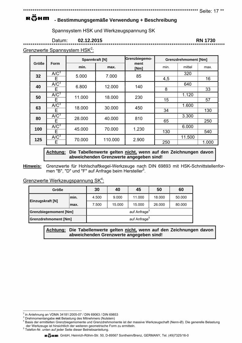
Grenzwerte Spannsystem HSK2:
Größe Form Spannkraft [N] Grenzbiegemo-
ment [Nm]
Grenzdrehmoment [Nm]
min. max. min. mittel max.
32 A/C3
5.000 7.000 85320
E 4,5 16
40 A/C3
6.800 12.000 140640
E 8 33
50 A/C3
11.000 18.000 230 1.120
E 15 57
63 A/C3
18.000 30.000 450 1.600
E 34 130
80 A/C3
28.000 40.000 810 3.300
E 65 250
100 A/C3
45.000 70.000 1.230 6.000
E 130 540
125 A/C3
70.000 110.000 2.900 11.500
E 250 1.000
Achtung: Die Tabellenwerte gelten nicht, wenn auf den Zeichnungen davon abweichenden Grenzwerte angegeben sind!
Hinweis: Grenzwerte für Hohlschaftkegel-Werkzeuge nach DIN 69893 mit HSK-Schnittstellenfor-men "B", "D" und "F" auf Anfrage beim Hersteller5.
Grenzwerte Werkzeugspannung SK4:
Größe 30 40 45 50 60
Einzugskraft [N] min. 4.500 9.000 11.000 18.000 50.000
max. 7.500 15.000 15.000 26.000 80.000
Grenzbiegemoment [Nm] auf Anfrage5
Grenzdrehmoment [Nm] auf Anfrage5
Achtung: Die Tabellenwerte gelten nicht, wenn auf den Zeichnungen davon abweichenden Grenzwerte angegeben sind!
2 in Anlehnung an VDMA 34181:2005-07 / DIN 69063 / DIN 69853 3 Drehmomentangabe mit Belastung des Mitnehmers (Nutstein) 4 Basis der ermittelten Grenzbiegemomente und Grenzdrehmomente ist der massive Werkzeugschaft (Nenn-Ø). Die generelle Belastung
der Werkzeuge ist hinsichtlich der weiteren geometrische Form zu ermitteln. 5 Telefon-Nr. unten auf jeder Seite dieser Betriebsanleitung.
******************************************************************************************** Seite: 18 **
- Allgemeine Gefahrenhinweise
Spannsystem HSK und Werkzeugspannung SK
Datum: 02.12.2015 RN 1730 **********************************************************************************************************
GmbH, Heinrich-Röhm-Str. 50, D-89567 Sontheim/Brenz, GERMANY, Tel. (49)7325/16-0
Warnung: Fehlerhafter Zusammenbau der Einzelteile kann die Sicherheit der gesamten Maschine gefährden. Bei fehlendem eigenem Fachpersonal darf das Spannmittel grundsätz-lich ausschließlich durch das Fachpersonal der Fa. RÖHM zerlegt und wieder zusammengesetzt werden.
I. Qualifikation des BedienersDieses HSK-Spannsystem bzw. der SK-Werkzeugspanner darf nur von Personen benutzt, einge-richtet und gewartet werden, welche hierzu besonders ausgebildet oder geschult sind, oder übereinschlägige, langjährige Erfahrungen verfügen.Personen, welche keine Erfahrungen im Umgang mit HSK-Spannsystemen bzw. SK-Werkzeugspannern aufweisen, sind durch unsachgemäßes Verhalten vor allem während der Ein-richtearbeiten durch die Spannbewegungen und -kräfte besonderen Verletzungsgefahren ausge-setzt.
II. VerletzungsgefahrenAus technischen Gründen kann diese Baugruppe teilweise aus spitzen und/oder scharfkantigenEinzelteilen bestehen. Um Verletzungsgefahren vorzubeugen, ist bei daran vorzunehmenden Tä-tigkeiten mit besonderer Vorsicht vorzugehen!
1. Ansteuerung
Um ein unbeabsichtigtes Umschalten des Betätigungsdrucks auf die Löse- oder Spannleitungzu verhindern, müssen in der hydraulischen Steuerung ausschließlich rastende Ventile ver-wendet werden.
2. Eingebaute Energiespeicher
Bewegliche Teile, die mit Druck-, Zug-, sonstigen Federn oder mit anderen elastischen Ele-menten vorgespannt sind, stellen durch die darin gespeicherte Energie ein Gefahrenpotentialdar. Dessen Unterschätzung kann zu schweren Verletzungen durch unkontrollierbare, ge-schossartig umherfliegende Einzelteile führen.Bevor weitere Arbeiten an den betroffenen Bauteilen durchgeführt werden können, ist diesegespeicherte Energie abzubauen. Spanneinrichtungen, die zerlegt werden sollen, sind des-halb mit Hilfe der zugehörigen Zusammenstellungszeichnungen auf derartige Gefahrenquellenhin zu untersuchen.Sollte das "Entschärfen" dieser gespeicherten Energie nicht gefahrlos möglich sein, darf dieDemontage nur von autorisierten Mitarbeitern der Fa. RÖHM durchzuführen.
Vorsicht: Von vorgespannten elastischen Elementen herausgeschleuderte Teile können, vor allem im Gesichtsbereich, Verletzungen verursa-chen. Die Spanneinheit SEH (3) bzw. der Werkzeugspanner ASP (3) darf nur vom Hersteller zerlegt werden. Augenschutz benutzen!
3. Die maximal zulässige Drehzahl
Die Betriebsdaten sind der Zusammenbauzeichnung zu entnehmen und dürfen nicht über-schritten werden.
Ist die maximale Drehzahl der Maschine größer als die für dieses HSK-Spannsystem bzw. fürdiesen SK-Werkzeugspanner zulässige, dann muss eine entsprechende Drehzahlbegrenzungan der Maschine aktiviert sein.
Sollten diese Werte aus von uns nicht zu vertretenden Gründen überschritten worden sein,sind Beschädigungen, auch wenn diese auf den ersten Blick nicht erkennbar sind, nicht aus-zuschließen.Diese Beschädigungen könnten die Gefahr von wegschleudernden Bauteilen und eventuell
******************************************************************************************** Seite: 19 **
- Allgemeine Gefahrenhinweise
Spannsystem HSK und Werkzeugspannung SK
Datum: 02.12.2015 RN 1730 **********************************************************************************************************
GmbH, Heinrich-Röhm-Str. 50, D-89567 Sontheim/Brenz, GERMANY, Tel. (49)7325/16-0
daraus resultierenden Personen- bzw. Sachschäden heraufbeschwören.
4. Überschreitung der zulässigen Drehzahl
Diese Einrichtung ist für umlaufenden Einsatz vorgesehen. Fliehkräfte - hervorgerufen durchüberhöhte Drehzahlen bzw. Umfangsgeschwindigkeiten - können bewirken, dass sich Einzel-teile lösen und dadurch zur potentiellen Gefahrenquelle für in der Nähe befindliche Personenoder Gegenstände werden.Der Betrieb mit höheren als den für diese Einrichtung vorgesehene Drehzahlen ist aus o. g.Gründen nicht zulässig.
Selbst eine einmalige Überschreitung von zulässigen Werten kann zu Schäden führen und ei-ne verdeckte, also nicht einfach erkennbare, Gefahrenquelle darstellen. In diesem Fall ist un-verzüglich der Hersteller zu informieren, damit dieser eine Überprüfung der Funktions- und Be-triebssicherheit durchführen kann. Nur so kann der weitere sichere Betrieb der Spanneinrich-tung gewährleistet werden.
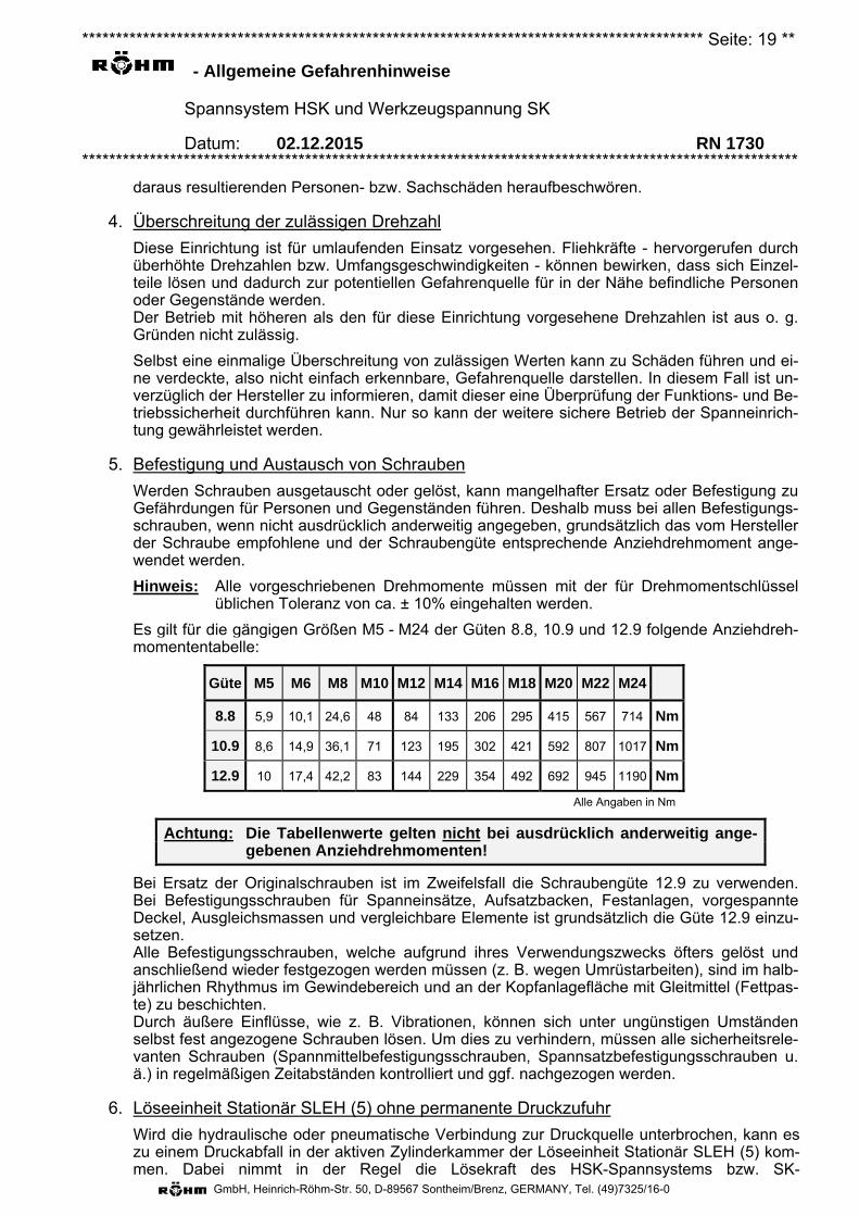
5. Befestigung und Austausch von Schrauben
Werden Schrauben ausgetauscht oder gelöst, kann mangelhafter Ersatz oder Befestigung zuGefährdungen für Personen und Gegenständen führen. Deshalb muss bei allen Befestigungs-schrauben, wenn nicht ausdrücklich anderweitig angegeben, grundsätzlich das vom Herstellerder Schraube empfohlene und der Schraubengüte entsprechende Anziehdrehmoment ange-wendet werden.
Hinweis: Alle vorgeschriebenen Drehmomente müssen mit der für Drehmomentschlüsselüblichen Toleranz von ca. ± 10% eingehalten werden.
Es gilt für die gängigen Größen M5 - M24 der Güten 8.8, 10.9 und 12.9 folgende Anziehdreh-momententabelle:
Güte M5 M6 M8 M10 M12 M14 M16 M18 M20 M22 M24
8.8 5,9 10,1 24,6 48 84 133 206 295 415 567 714 Nm
10.9 8,6 14,9 36,1 71 123 195 302 421 592 807 1017 Nm
12.9 10 17,4 42,2 83 144 229 354 492 692 945 1190 Nm
Alle Angaben in Nm
Achtung: Die Tabellenwerte gelten nicht bei ausdrücklich anderweitig ange-gebenen Anziehdrehmomenten!
Bei Ersatz der Originalschrauben ist im Zweifelsfall die Schraubengüte 12.9 zu verwenden. Bei Befestigungsschrauben für Spanneinsätze, Aufsatzbacken, Festanlagen, vorgespannte Deckel, Ausgleichsmassen und vergleichbare Elemente ist grundsätzlich die Güte 12.9 einzu-setzen. Alle Befestigungsschrauben, welche aufgrund ihres Verwendungszwecks öfters gelöst und anschließend wieder festgezogen werden müssen (z. B. wegen Umrüstarbeiten), sind im halb-jährlichen Rhythmus im Gewindebereich und an der Kopfanlagefläche mit Gleitmittel (Fettpas-te) zu beschichten. Durch äußere Einflüsse, wie z. B. Vibrationen, können sich unter ungünstigen Umständen selbst fest angezogene Schrauben lösen. Um dies zu verhindern, müssen alle sicherheitsrele-vanten Schrauben (Spannmittelbefestigungsschrauben, Spannsatzbefestigungsschrauben u. ä.) in regelmäßigen Zeitabständen kontrolliert und ggf. nachgezogen werden.
6. Löseeinheit Stationär SLEH (5) ohne permanente Druckzufuhr
Wird die hydraulische oder pneumatische Verbindung zur Druckquelle unterbrochen, kann eszu einem Druckabfall in der aktiven Zylinderkammer der Löseeinheit Stationär SLEH (5) kom-men. Dabei nimmt in der Regel die Lösekraft des HSK-Spannsystems bzw. SK-
******************************************************************************************** Seite: 20 **
- Allgemeine Gefahrenhinweise
Spannsystem HSK und Werkzeugspannung SK
Datum: 02.12.2015 RN 1730 **********************************************************************************************************
GmbH, Heinrich-Röhm-Str. 50, D-89567 Sontheim/Brenz, GERMANY, Tel. (49)7325/16-0
Werkzeugspanners ab und das Werkzeug kann nicht mehr entnommen bzw. ausgewechselt werden. Daher muss der Lösedruck während des gesamten Entnahme- und Zuführvorgangs unterbre-chungsfrei aufrechterhalten werden.
Achtung: Während des umlaufenden Betriebes muss hydraulischer Druck unter-brechungsfrei auf den Spannanschluss der Löseeinheit Stationär SLEH (5) wirken.
7. Instandhaltungsungsarbeiten
Die Zuverlässigkeit und Sicherheit von Spannsystem HSK bzw. Werkzeugspannung SK kannnur dann gewährleistet werden, wenn die Instandhaltungsvorschriften der Betriebsanleitunggenau befolgt werden.
Es ist vorteilhaft, nach spätestens 200 Spannhüben die internen bewegten Teile mehrmals biszu ihren Endstellungen durchzufahren. (Weggedrücktes Schmiermittel wird dadurch wieder andie Druckflächen herangeführt. Die Spannkraft bleibt somit für längere Zeit erhalten).
8. Gefährdung durch Herausschleudern
Um den Bediener vor herausschleudernden Teilen zu schützen, muss nach DIN EN 23125 ei-ne trennende Schutzeinrichtung an der Werkzeugmaschine vorhanden sein.
III. Kontrollen1. Hubkontrolle
Wird ein Spannsystem HSK mit Hubkontrolleinrichtung neu montiert, muss die Hubkontrollein-richtung auf die neue Situation abgestimmt werden.
2. Instandhaltungskontrollen
Die Zuverlässigkeit und Sicherheit des Spannsystem HSK kann nur dann gewährleistet wer-den, wenn die Instandhaltungsvorschriften der Betriebsanleitung genau befolgt werden.
3. Kraftkontrollen
In regelmäßigen Abständen muss die Spannkraft des Spannsystem HSK mit einem Spann-kraftmessgerät kontrolliert werden.
IV. Umweltgefahren1. Stoffe
Zum Betrieb eines Spannsystem HSK werden z. T. die unterschiedlichsten Medien für BetriebSchmierung, Kühlung, Reinigung etc. benötigt. Diese werden dem HSK-Spannsystem bzw.SK-Werkzeugspanner in der Regel über die Löseeinheit Stationär SLEH (5) oder die Kühlmit-tel-Drehdurchführung (6) zugeführt. Die am häufigsten auftretenden sind Hydrauliköl, Kühlmit-tel und geölte Druckluft. Beim Umgang mit dem HSK-Spannsystem bzw. SK-Werkzeugspanner muss sorgfältig auf diese Medien geachtet werden, damit sie nicht in Bo-den bzw. Wasser gelangen können, Achtung Umweltgefährdung!
Dies gilt insbesondere
– während der Montage/Demontage, da sich in den Leitungen, den Komponenten und denKolbenräumen noch Restmengen befinden können,
– für poröse, defekte oder nicht fachgerecht montierte Dichtungen,
– für Kühlmittel und/oder Blasluft, welches aus konstruktiven oder fertigungstechnischenGründen während des Betriebs aus dem HSK-Spannsystem bzw. SK-Werkzeugspanner
******************************************************************************************** Seite: 21 **
- Allgemeine Gefahrenhinweise
Spannsystem HSK und Werkzeugspannung SK
Datum: 02.12.2015 RN 1730 **********************************************************************************************************
GmbH, Heinrich-Röhm-Str. 50, D-89567 Sontheim/Brenz, GERMANY, Tel. (49)7325/16-0
austritt bzw. aus diesem herausgeschleudert wird.
Diese austretenden Stoffe müssen daher aufgefangen und wieder verwendet bzw. den ein-schlägigen Vorschriften entsprechend entsorgt werden!
2. Lärm
In sehr seltenen Fällen kann der Betrieb von rotierenden Baugruppen Schallemissionen frei-setzen. Diese werden in der Regel während der Inbetriebnahme festgestellt.Sollten sich diese Emissionen nicht durch konstruktive Maßnahmen an dem HSK-Spannsystem bzw. SK-Werkzeugspanner oder fertigungstechnische Maßnahmen beseitigenlassen, muss vom Hersteller oder Betreiber der Maschine ggf. eine geeignete Schalldämmungan der Maschine vorgesehen werden.
V. Sicherheitstechnische Anforderungen an das Spannsystem HSK bzw.die Werkzeugspannung SK1. Die tatsächliche Position des HSK-Spannsystems bzw. SK-Werkzeugspanners muss (z. B.
über den Hubkontrollring (32)) erfasst und von der Maschinensteuerung mit Blick auf die An-steuerung des Werkzeugspindelantriebes verarbeitet werden.
2. Die Werkzeugspindel darf erst anlaufen, wenn in der Löseeinheit Stationär SLEH (5) der Lö-sedruck ab- und der Spanndruck aufgebaut wurde und die Spannung im zulässigen Arbeits-bereich erfolgt ist.
3. Das Lösen der Werkzeugspannung darf ausschließlich während des Stillstandes der Werk-zeugspindel möglich sein.
4. Wird der zulässige Arbeitsbereich der Spannung verlassen, muss ein Signal die Werk-zeugspindel unverzüglich stillsetzen.
5. Wird die Werkzeugspindel stillgesetzt, muss das Werkzeug bis zum Werkzeugspindelstillstandfest eingespannt bleiben.
6. Bei Stromausfall und anschließender -wiederkehr muss die Möglichkeit einer Änderung dermomentanen Schaltstellung ausgeschlossen sein.
******************************************************************************************** Seite: 22 **
- Bedienung
Spannsystem HSK und Werkzeugspannung SK
Datum: 02.12.2015 RN 1730 **********************************************************************************************************
GmbH, Heinrich-Röhm-Str. 50, D-89567 Sontheim/Brenz, GERMANY, Tel. (49)7325/16-0
Wichtig: Bricht ein Teil der Segmentspannzange HSK (11) bzw. SK (11), dann darf das HSK-Spannsystem / die Werkzeugspannung SK erst nach dem Austausch des gesamten Spann-Satz HSK (1) bzw. SK (1) weiterbetrieben werden.
Personalqualifikation Das Spannsystem HSK bzw. der Werkzeugspanner SK kann von unterwiesenem Personal betrie-ben (im automatisierten Betrieb) werden. Die unterwiesene Person muss nachweislich in einer Un-terweisung durch den Betreiber über die ihr übertragenen Aufgaben und möglichen Gefahren bei unsachgemäßem Verhalten unterrichtet sein.
Persönliche Schutzausrüstung 1. Folgende persönliche Schutzausrüstung muss getragen werden:
Augenschutz.
Handschutz.
Kopfschutz
Warnung: Scharfkantige Bauteile können Schnittverletzungen verursachen. Gliedmaßen von scharfkantigen Bauteilen fernhalten.
Handschutz benutzen.
Drehzahlbegrenzung 1. Wird während des Betriebes die Werkzeugspindel in Rotation versetzt, ohne dass ein Werkzeug
mit dem Spannsystem HSK / der Werkzeugspannung SK gespannt ist, dann muss zuvor sicher-gestellt werden, dass die max. Drehzahl 500 min-1 nicht überschreiten kann.
Funktionsablauf
1. Durchgeführte Medien
– Bei stillgesetzter Maschinenspindel muss sichergestellt sein, dass die Medienzuführungen fürFluide drucklos geschaltet sind.
– Bei geeigneten Drehdurchführungen (6) ist während der Dauer des automatischen Werk-zeugwechsels eine Umschaltung von Kühlmittel auf Druckluft zulässig.
Warnung: Unter hohem Druck austretende Flüssigkeiten oder Gase können vor allem im Gesichtsbereich schwere Verletzungen und/oder evtl. Verbrühungen verursachen. Vor dem manuellen Werkzeugwechsel die Drucklosigkeit der Druckan-schlüsse und deren Leitungen kontrollieren. Aktiv belüften. Augenschutz benutzen!
2. Einsetzen des Werkzeuges
Wichtig: Das Einsetzen des Werkzeuges erfolgt ausschließlich bei Stillstand der Werkzeugspindel.
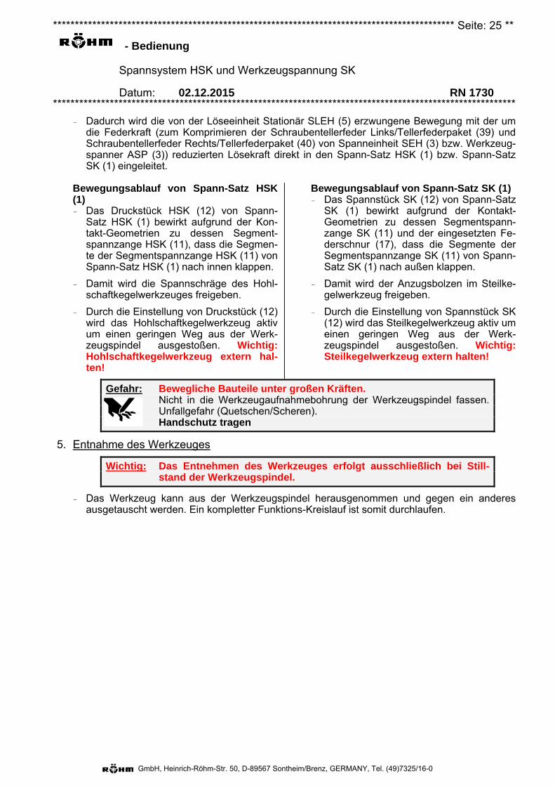
Gefahr: Bewegliche Bauteile unter großen Kräften. Nicht in die Werkzeugaufnahmebohrung der Werkzeugspindel fassen. Unfallgefahr (Quetschen/Scheren). Handschutz benutzen.
******************************************************************************************** Seite: 23 **
- Bedienung
Spannsystem HSK und Werkzeugspannung SK
Datum: 02.12.2015 RN 1730 **********************************************************************************************************
GmbH, Heinrich-Röhm-Str. 50, D-89567 Sontheim/Brenz, GERMANY, Tel. (49)7325/16-0
Das Werkzeug muss sowohl bei manuellem als auch bei maschinellem Einsetzen in die Werk-zeugspindel
– so genau (Koaxialität < 0.5 mm, gilt für alle Größen) zugeführt werden, dass eine Beschädi-gung (z. B. des Kühlmittelsrohrs) oder Fehlspannung ausgeschlossen ist.
– so lange aktiv nachgeschoben werden, bis der Spannvorgang (siehe unten) vollständig abge-schlossen ist.
Hinweis: Die Spannkraft sowie das Einstellmaß von Druckstück HSK (12) bzw. SpannstückSK (12) ist regelmäßig zu prüfen. Siehe dazu auch die Kapitel "Montage" und "In-standhaltung".
3. Spannen des Werkzeuges
Wichtig: Das Spannen des Werkzeuges erfolgt ausschließlich bei Stillstand der Werkzeugspindel.
Bewegungsablauf der Löseeinheit Stationär SLEH (5) – Beim Spannvorgang wird der Druckkolben (52) der Löseeinheit Stationär SLEH (5) hydrau-
lisch betätigt aktiv vom Hubkontrollring (32) der Spanneinheit SEH (3) abgehoben und bis aufAnschlag am Aufnahmedeckel (53) zurückgefahren.
– Ein mechanischer Kontakt zwischen Druckkolben (52) der Löseeinheit Stationär SLEH (5) undHubkontrollring (32) der Spanneinheit SEH (3) besteht nicht mehr.
– Um eine ungewollte Positionsänderung von Druckkolben (52) auszuschließen muss derSpanndruck während der gesamten Spannzeit aufrecht erhalten werden
Bewegungsablauf der Spanneinheit SEH (3) – Beim Spannvorgang drücken die Schrau-
bentellerfeder Links/Tellerfederpaket (39)und SchraubentellerfederRechts/Tellerfederpaket (40) der Span-neinheit SEH (3) deren Führungskolben(31) von der Werkzeugspindelöffnungweg nach hinten.
– Die Hubbewegung der Spanneinheit SEH(3) dauert solange an, bis der Spannvor-gang durch Kraftschluss vollständig ab-geschlossen ist.
Bewegungsablauf von Werkzeugspanner ASP (3) – Beim Spannvorgang drücken die Schrau-
bentellerfeder Links/Tellerfederpaket (39)und SchraubentellerfederRechts/Tellerfederpaket (40) von Werk-zeugspanner ASP (3) dessen Zugstange(31) von der Werkzeugspindelöffnungweg nach hinten.
– Die Hubbewegung von WerkzeugspannerASP (3) dauert solange an, bis derSpannvorgang durch Kraftschluss voll-ständig abgeschlossen ist.
Bewegungsablauf der Zugstangenverlängerung (2) – Da der Führungskolben (31) von Spanneinheit SEH (3) und das Druckstück HSK (12) von
Spann-Satz HSK (1) bzw. die Zugstange (31) von Werkzeugspanner ASP (3) und das Spann-stück SK (12) von Spann-Satz SK (1) über die Zugstangenverlängerung (2) direkt miteinanderverschraubt sind, wird die von der Spanneinheit SEH (3) bzw. die von Werkzeugspanner ASP(3) erzeugte Betätigungskraft direkt in den Spann-Satz HSK (1) und dessen Druckstück HSK(12) bzw. in den Spann-Satz SK (1) und dessen Spannstück SK (12) eingeleitet.
Bewegungsablauf Spann-Satz
Wichtig: Um eine unzureichende oder mangelhafte Werkzeugspannung rechtzeitig erkennen zu können, muss die korrekte axiale Position von Druckstück HSK (12) bzw. Spannstück SK (12) kontrolliert wer-den. Dazu muss das Spannsystem / die Werkzeugspannung mit ei-ner Hubkontrolleinrichtung überwacht werden.
******************************************************************************************** Seite: 24 **
- Bedienung
Spannsystem HSK und Werkzeugspannung SK
Datum: 02.12.2015 RN 1730 **********************************************************************************************************
GmbH, Heinrich-Röhm-Str. 50, D-89567 Sontheim/Brenz, GERMANY, Tel. (49)7325/16-0
(a) Spann-Satz HSK (1)– Das Druckstück HSK (12) von Spann-Satz HSK (1) drückt während der Spannbewegung
die Segmente von dessen Segmentspannzange HSK (11) in die Spannschräge des Hohl-schaftkegelwerkzeuges.
– Durch die Spannschräge des Hohlschaftkegelwerkzeuges sowie der Form der Segment-spannzange HSK (11) von Spann-Satz HSK (1) wird eine Axialkraft erzeugt, welche alssog. "Spannkraft" auf das Hohlschaftkegelwerkzeug einwirkt.
Hinweis: Während des gesamten Spannvorganges muss das Hohlschaftkegelwerkzeugaktiv in die Werkzeugspindelbohrung nachgeschoben werden.
– Die Kraftwirkung bleibt während des gespannten Zustandes erhalten.
(b) Spann-Satz SK (1)– Das Spannstück SK (12) von Spann-Satz SK (1) drückt während der Spannbewegung die
Segmente von dessen Segmentspannzange SK (11) in die Spannschräge des Anzugs-bolzens in dem Steilkegelwerkzeug.
– Durch die Spannschräge des Anzugsbolzens in dem Steilkegelwerkzeug sowie der Formder Segmentspannzange SK (11) von Spann-Satz SK (1) wird eine Axialkraft erzeugt,welche als sog. "Einzugskraft" auf das Steilkegelwerkzeug einwirkt.
Hinweis: Während des gesamten Spannvorganges muss das Steilkegelwerkzeug aktivin die Werkzeugspindelbohrung nachgeschoben werden.
– Die Kraftwirkung bleibt während des gespannten Zustandes erhalten.
4. Lösen des Werkzeuges
Wichtig: Das Lösen des Werkzeuges erfolgt ausschließlich bei Stillstand der Werkzeugspindel.
Bewegungsablauf der der Löseeinheit Stationär SLEH (5) – Beim Lösevorgang fährt der Druckkolben (52) der Löseeinheit Stationär SLEH (5) hydraulisch
betätigt auf den Hubkontrollring (32) der Spanneinheit SEH (3) bzw. auf den Druckkolben (46)von Werkzeugspanner ASP (3) und drückt diesen entgegen der Kräfte von dessen Schrau-bentellerfeder Links/Tellerfederpaket (39) und Schraubentellerfeder Rechts/Tellerfederpaket(40) nach vorn.
Hinweis: In Sonderfällen ist auch ein externer Anschlag von Druckkolben (52) (auch ggf.über weitere Komponenten des HSK-Spannsystems bzw. der SK-Werkzeugspannung) möglich. Siehe zugehörige Zusammenstellungszeichnung.
– Der Anschlag von Druckkolben (52) der Löseeinheit Stationär SLEH (5) nach vorn erfolgt inderen Gehäuse (51).
Bewegungsablauf der Spanneinheit SEH (3) – Durch das Zusammendrücken der
Schraubentellerfeder Links/Tellerfederpa-ket (39) und SchraubentellerfederRechts/Tellerfederpaket (40) der Spann-einheit SEH (3) wird deren Führungs-kolben (31) nach vorn in Richtung zurWerkzeugspindelöffnung geschoben.
Bewegungsablauf von Werkzeugspanner ASP (3) – Durch das Zusammendrücken der
Schraubentellerfeder Links/Tellerfederpa-ket (39) und SchraubentellerfederRechts/Tellerfederpaket (40) von Werk-zeugspanner ASP (3) wird dessen Zug-stange (31) nach vorn in Richtung zurWerkzeugspindelöffnung geschoben.
Bewegungsablauf der Zugstangenverlängerung (2) – Da Der Führungskolben (31) von Spanneinheit SEH (3) und das Druckstück HSK (12) von
Spann-Satz HSK (1) bzw. die Zugstange (31) von Werkzeugspanner ASP (3) mit dem Spann-stück SK (12) von Spann-Satz SK (1) sind über die Zugstangenverlängerung (2) direkt mitei-nander verschraubt.
******************************************************************************************** Seite: 25 **
- Bedienung
Spannsystem HSK und Werkzeugspannung SK
Datum: 02.12.2015 RN 1730 **********************************************************************************************************
GmbH, Heinrich-Röhm-Str. 50, D-89567 Sontheim/Brenz, GERMANY, Tel. (49)7325/16-0
– Dadurch wird die von der Löseeinheit Stationär SLEH (5) erzwungene Bewegung mit der um die Federkraft (zum Komprimieren der Schraubentellerfeder Links/Tellerfederpaket (39) und Schraubentellerfeder Rechts/Tellerfederpaket (40) von Spanneinheit SEH (3) bzw. Werkzeug-spanner ASP (3)) reduzierten Lösekraft direkt in den Spann-Satz HSK (1) bzw. Spann-Satz SK (1) eingeleitet.
Bewegungsablauf von Spann-Satz HSK (1) – Das Druckstück HSK (12) von Spann-
Satz HSK (1) bewirkt aufgrund der Kon-takt-Geometrien zu dessen Segment-spannzange HSK (11), dass die Segmen-te der Segmentspannzange HSK (11) von Spann-Satz HSK (1) nach innen klappen.
– Damit wird die Spannschräge des Hohl-schaftkegelwerkzeuges freigeben.
– Durch die Einstellung von Druckstück (12) wird das Hohlschaftkegelwerkzeug aktiv um einen geringen Weg aus der Werk-zeugspindel ausgestoßen. Wichtig: Hohlschaftkegelwerkzeug extern hal-ten!
Bewegungsablauf von Spann-Satz SK (1) – Das Spannstück SK (12) von Spann-Satz
SK (1) bewirkt aufgrund der Kontakt-Geometrien zu dessen Segmentspann-zange SK (11) und der eingesetzten Fe-derschnur (17), dass die Segmente der Segmentspannzange SK (11) von Spann-Satz SK (1) nach außen klappen.
– Damit wird der Anzugsbolzen im Steilke-gelwerkzeug freigeben.
– Durch die Einstellung von Spannstück SK (12) wird das Steilkegelwerkzeug aktiv um einen geringen Weg aus der Werk-zeugspindel ausgestoßen. Wichtig: Steilkegelwerkzeug extern halten!
Gefahr: Bewegliche Bauteile unter großen Kräften. Nicht in die Werkzeugaufnahmebohrung der Werkzeugspindel fassen.
Unfallgefahr (Quetschen/Scheren). Handschutz tragen
5. Entnahme des Werkzeuges
Wichtig: Das Entnehmen des Werkzeuges erfolgt ausschließlich bei Still-stand der Werkzeugspindel.
– Das Werkzeug kann aus der Werkzeugspindel herausgenommen und gegen ein anderes ausgetauscht werden. Ein kompletter Funktions-Kreislauf ist somit durchlaufen.
******************************************************************************************** Seite: 26 **
- Montage
Spannsystem HSK und Werkzeugspannung SK
Datum: 02.12.2015 RN 1730 **********************************************************************************************************
GmbH, Heinrich-Röhm-Str. 50, D-89567 Sontheim/Brenz, GERMANY, Tel. (49)7325/16-0
I. PersonalqualifikationDie Montage von Spannsystem HSK bzw. Werkzeugspanner SK an/in die Werkzeugspindel darfnur durch ausgebildetes Fachpersonal des Herstellers der Werkzeugspindel, der Maschineoder des Spannsystems ausgeführt werden, das aufgrund seiner fachlichen Ausbildung mit denübertragenen Arbeiten sowie den möglichen Gefahren vertraut und in der Lage ist, diese durchgeeignete Sicherheitsmaßnahmen zu minimieren.
II. Persönliche Schutzausrüstung1. Folgende persönliche Schutzausrüstung muss getragen werden:
Augenschutz.
Kopfschutz.
Handschutz.
Fußschutz.
Warnung: Scharfkantige Bauteile können Schnittverletzungen verursachen. Gliedmaßen von scharfkantigen Bauteilen fernhalten.
Handschutz benutzen.
Gefahr: Durch unzureichende mechanische Festigkeit oder Überbelastung (Biegung, Drehmoment) können aus der Spannung herausgerissene Teile/Werkzeuge schwere Verletzungen verursachen. Persönliche Schutzausrichtung tragen.
III. Platzbedarf1. Der verfügbare Arbeitsraum am Werkzeugspindelende zur Montage von Spannsystem HSK
bzw. Werkzeugspannung SK sollte min. 1x Werkzeugspindellänge betragen.
IV. Anziehdrehmomente für Zylinderschrauben1. Müssen für die Montage oder Demontage bzw. für den Betrieb des Spannsystems Zylinder-
schrauben (nach DIN 912 + DIN 6912) gelöst oder festgezogen werden, dann sind grundsätz-lich die Anziehdrehmomente nach der VDI-Richtlinie 2230 anzuwenden.
2. Nur so ist die größtmögliche Festigkeit der Zylinderschraube gewährleistet.
3. Eine Auswahl dieser Anziehdrehmomente für die üblichen Schraubengrößen und für 3 ver-schiedene Schraubengüten (8.8 bis 12.9) sind in der Anziehdrehmomententabelle im Kapitel"Allgemeine Gefahrenhinweise" im Absatz "Befestigung und Austausch von Schrauben"zu finden.
4. Bei diesem Spannsystem wird nahezu ausschließlich die Schraubengüte 12.9 verwendet. ImZweifelsfall auf der Stückliste nachschauen: dort sind die Schraubengüten für Normschraubenangegeben. Die Schraubengüte kann außerdem auf dem Schraubenkopf zu finden sein.
5. Von dieser Vorgabe abweichende Anziehdrehmomente für Schrauben, welche im Rahmenvon Montage oder Demontage bzw. während des Betriebs des Spannsystems gelöst oderfestgezogen werden müssen, sind auf der Zusammenstellungszeichnung angegeben.
V. Drehzahlbegrenzung1. Muss die Werkzeugspindel während der Montage bzw. Inbetriebnahme von Spannsystem
HSK bzw. Werkzeugspannung SK in Rotation versetzt werden, dann muss zuvor sichergestelltwerden, dass die max. Drehzahl 500 min-1 nicht überschritten werden kann.
******************************************************************************************** Seite: 27 **
- Montage
Spannsystem HSK und Werkzeugspannung SK
Datum: 02.12.2015 RN 1730 **********************************************************************************************************
GmbH, Heinrich-Röhm-Str. 50, D-89567 Sontheim/Brenz, GERMANY, Tel. (49)7325/16-0
VI. Drücke 1. Abgesehen zu Prüfzwecken muss während der gesamten Montageschritte sowie im Einrichte-
betrieb jeglicher Betätigungsdruck abgestellt sein.
VII. Durchgeführte Medien (bei Montage / Inbetriebnahme von Einzelkomponenten)
1. Vor Beginn der Arbeiten muss sichergestellt sein, dass alle Medienzuführungen drucklos ge-schaltet und aktiv belüftet sind.
VIII. Montage Spanneinheit SEH (3) bzw. Werkzeugspanner ASP (3) + Zug-stangenverlängerung (2)
Vorsicht: Von vorgespannten elastischen Elementen herausgeschleuderte Teile können, vor allem im Gesichtsbereich, Verletzungen verursa-chen.
Die Spanneinheit SEH (3) bzw. der Werkzeugspanner ASP (3) darf nur vom Hersteller zerlegt werden.
Augenschutz benutzen!
1. Anlieferung
1. Die Zugstangenverlängerung (2) wird bereits komplett mit der Spanneinheit SEH (3) bzw. dem Werkzeugspanner ASP (3) verschraubt und mit 2 Gewindestiften (24) gesichert ange-liefert.
Warnung: Durch unsachgemäße Drehmomenteinleitung können Bauteile über-lastet und zerstört werden. Dabei können sich vorgespannte elasti-sche Elemente explosionsartig entspannen.
Die Verschraubung der Zugstangenverlängerung (2) mit der Spanneinheit SEH (3) bzw. dem Werkzeugspanner ASP (3) darf ausschließlich vom Hersteller des Spannsystem HSK bzw. der Werkzeugspannung SK wieder gelöst bzw. verschraubt werden. Siehe auch Hinweis oben.
2. Vorbereitung Werkzeugspindel
1. Die Bohrung der Werkzeugspindel reinigen und auf Rund- und Planlauf kontrollieren. Max. zul. Fehler (je nach Höhe der Spindeldrehzahl) max. 0,02 mm.
3. Vorbereitung Spanneinheit SEH (3) bzw. Werkzeugspanner ASP (3)
1. Alle Komponenten müssen unbeschädigt vorliegen.
Warnung: Von Bearbeitungskräften aus der Spannung herausgerissene Tei-le/Werkzeuge können schwere Verletzungen verursachen.
Keine beschädigten Bauteile verwenden.
2. Alle Komponenten müssen schmutzfrei sein.
3. Die Schraubentellerfeder Links/Tellerfederpaket (39) und Schraubentellerfeder Rechts/Tellerfederpaket (40) der Spanneinheit SEH (3) bzw. von Werkzeugspanner ASP (3) müssen mit Fett F80* gefettet sein.
Spannein-heit SEH (3)
(Spannsyssys- tem HSK)
4. Die Abstimmscheibe (22) der Zugstangenverlängerung (2) von deren Zugstangenverlänge-rung (21) herunternehmen.
* Empfohlenes Fett F80 Gebinde [kg] 0,1 0,25 0,5 1 5 25 Id.-Nr. 630869 304345 308555 028975 318310 658047
******************************************************************************************** Seite: 28 **
- Montage
Spannsystem HSK und Werkzeugspannung SK
Datum: 02.12.2015 RN 1730 **********************************************************************************************************
GmbH, Heinrich-Röhm-Str. 50, D-89567 Sontheim/Brenz, GERMANY, Tel. (49)7325/16-0
4. Montage Spanneinheit SEH (3) bzw. Werkzeugspanner ASP (3) mit Zugstangenver-längerung (2)
1. Die Spanneinheit SEH (3) bzw. den Werkzeugspanner ASP (3) mit der verschraubten Zug-stangenverlängerung (2) von hinten bis auf Anschlag in die Werkzeugspindel einführen.
Spanneinheit SEH (3) (Spannsystem HSK) 2. Die Abstimmscheibe (22) der Zugstangenverlängerung (2) von vorn in die Werkzeugspin-
delbohrung ein- und auf die Zugstangenverlängerung (21) der Zugstangenverlängerung (2)aufschieben.
Hinweis: Die Abstimmscheibe (22) der Zugstangenverlängerung (2) ist mit mehrerenGewindebohrungen versehen. Mit Hilfe dieser Gewinde und passenden langen Schrauben kann die Montage/Demontage der Abstimmscheibe (22) der Zug-stangenverlängerung (2) vereinfacht werden.
Spannsystem HSK bzw. Werkzeugspanner SK 3. Die Gesamteinheit mit den vorgegebenen Maßen kontrollieren. Siehe Zusammenstellungs-
zeichnung im Anhang.
IX. Montage Löseeinheit Stationär SLEH (5)1. Anlieferung
1. Die Löseeinheit Stationär SLEH (5) wird komplett vormontiert angeliefert.
2. Werkzeugspindel vorbereiten
1. Es muss ein zum Werkzeugspindelgehäuse passender Adapterflansch mit Aufnahme- bzw.Montagemöglichkeiten für mehrere Hubkontrollschalter vorhanden und an das Werk-zeugspindelgehäuse montiert sein.
2. Das vorgeschriebene Maß zwischen Werkzeugspindelende und der Anschraubfläche vonGehäuse (51) der Löseeinheit Stationär SLEH (5) an dem Adapterflansch muss eingehal-ten werden. Siehe Zeichnungen im Anhang. Ggf. muss die Dicke der Abstimmscheibe (55)innerhalb der ebenfalls vorgegebenen Toleranzen abgestimmt werden.
3. Montage Löseeinheit Stationär SLEH (5)
1. Mit dem vorgeschriebenen Anziehdrehmoment (siehe Hinweis) die komplette LöseeinheitStationär SLEH (5) mit den Zylinderschrauben (54) an dem stationär an dem Werk-zeugspindelgehäuse befestigten Adapterflansch anschrauben.
Hinweis: Das vorgeschriebene Anziehdrehmoment für die Zylinderschrauben (54) ist ne-ben diesen auf dem Aufnahmedeckel (53) angegeben. Sollte das nicht der Fall sein, so ist das vorgeschriebene Anziehdrehmoment aus der Anziehdrehmomententabelle im Kapitel "Allgemeine Gefahrenhinwei-se" im Absatz "Befestigung und Austausch von Schrauben" zu entnehmen. Siehe auch Punkt IV.
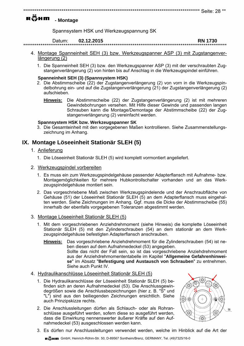
4. Hydraulikanschlüsse Löseeinheit Stationär SLEH (5)
1. Die Hydraulikanschlüsse der Löseeinheit Stationär SLEH (5) be-finden sich an deren Aufnahmedeckel (53). Die Anschlussgewin-degrößen sowie die Anschlussbezeichnungen (hier z. B. "S" und"L") sind aus den beiliegenden Zeichnungen ersichtlich. Sieheauch Prinzipskizze rechts.
2. Die Anschlussleitungen dürfen als Schlauch- oder als Rohran-schlüsse ausgeführt werden, sofern diese so ausgeführt werden,dass die Einwirkung nennenswerter äußerer Kräfte auf den Auf-nahmedeckel (53) ausgeschlossen werden kann.
3. Es dürfen nur Anschlussleitungen verwendet werden, welche im Hinblick auf die Art der
S L
******************************************************************************************** Seite: 29 **
- Montage
Spannsystem HSK und Werkzeugspannung SK
Datum: 02.12.2015 RN 1730 **********************************************************************************************************
GmbH, Heinrich-Röhm-Str. 50, D-89567 Sontheim/Brenz, GERMANY, Tel. (49)7325/16-0
Medien, deren Drücke sowie die Umwelteinflüsse für den Einsatzfall geeignet sind.
4. Um eventuelle Verunreinigungen aus den Anschlussleitungen zu entfernen, sollten diesevor Anschluss an den Aufnahmedeckel (53) mit dem später vorgesehenem Durch-flussmedium durchgespült bzw. durchgeblasen werden.
5. Die Verschlusskappen aus den Hydraulikanschlüssen in Aufnahmedeckel (53) herausneh-men.
Hinweis: Da die Verschlusskappen im Falle einer späteren Demontage der LöseeinheitStationär SLEH (5) nützlich sein könnten, wird empfohlen, diese sorgfältig auf-zubewahren. In die Löseeinheit Stationär SLEH (5) eindringende Verschmutzungen sind auf jeden Fall zu vermeiden, da ansonsten mit vorzeitigem Verschleiß an dyna-misch belasteten Dichtungen und Gleitflächen gerechnet werden muss.
6. Die. Hydraulikanschlüsse an den Aufnahmedeckel (53) herstellen. Die Anziehdrehmomentefür die Verschraubungen müssen den beiliegenden Zeichnungen entnommen werden.
Hinweis: Bei der Erstbefüllung der Löseeinheit Stationär SLEH (5) mit Hydrauliköl denHydraulikdruck auf max. 10 bar reduzieren.
X. Montage Kühlmittel-Drehdurchführung (6)– Es stehen mehrere unterschiedliche Typen, handelsüblicher Kühlmittel-Drehdurchführungen zur
Auswahl. Je nach HSK-Spannsystem liegt der Lieferung eine der folgenden Kühlmittel-Dreh-durchführungen (6) bei:
– Die Montage ist der entsprechenden der beiliegenden Anleitungen zu entnehmen:
ROTOFLUX Bedienungsanleitung RN 1727 "Allgemeine Betriebsanweisung
Kühlmittel-Drehdurchführung "ROTOFLUX".
"ROTOFLUX Montage- und Einlaufanweisung" (eng-lisch/italienisch).
DEUBLIN
"Betriebsanleitung 040-555x DEUBLIN".
"DEUBLIN Installation 040-505".
GAT "GAT Rotodisk Betriebsanleitung".
– Nach der Montage der Anschlüsse noch einmal kontrollieren, ob kein Vertauschen vonZuführung/Leckage vorliegt.
Hinweise: Auf den Webseiten des Herstellers können die aktuellen Informationen zu deren Kühl-mittel-Drehdurchführungen abgerufen werden. Die Web-Adressen sind im Kapitel "Be-stimmungsgemäße Verwendung + Beschreibung" unter dem Abschnitt "Kühlmittel-Drehdurchführung (6)" aufgeführt. Bei der Erstbeaufschlagung der Kühlmittel-Drehdurchführung (6) mit dem vorgesehe-nen Medium dessen Druck zunächst auf max. 10 bar (Flüssigkeiten) bzw. 3 bar (Gase) reduzieren.
Kühlmittel-Dreh-durchführung ROTOFLUX
Kühlmittel-Dreh-durchführung DEUBLIN
Kühlmittel-Dreh-durchführung GAT
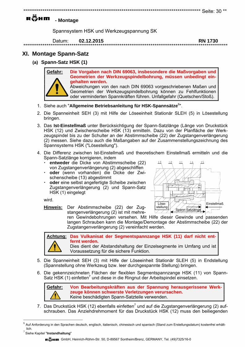
******************************************************************************************** Seite: 30 **
- Montage
Spannsystem HSK und Werkzeugspannung SK
Datum: 02.12.2015 RN 1730 **********************************************************************************************************
GmbH, Heinrich-Röhm-Str. 50, D-89567 Sontheim/Brenz, GERMANY, Tel. (49)7325/16-0
XI. Montage Spann-Satz
(a) Spann-Satz HSK (1)
Gefahr: Die Vorgaben nach DIN 69063, insbesondere die Maßvorgaben und Geometrien der Werkzeugspindelbohrung, müssen unbedingt ein-gehalten werden. Abweichungen von den nach DIN 69063 vorgeschriebenen Maßen und Geometrien der Werkzeugspindelbohrung können zu Fehlfunktionen oder verminderten Spannkräften führen. Unfallgefahr (Quetschen/Stoß).
1. Siehe auch "Allgemeine Betriebsanleitung für HSK-Spannsätze6".
2. Die Spanneinheit SEH (3) mit Hilfe der Löseeinheit Stationär SLEH (5) in Lösestellungbringen.
3. Das Ist-Einstellmaß unter Berücksichtigung der Spann-Satzlänge (Länge von DruckstückHSK (12) und Zwischenscheibe HSK (13) ermitteln. Dazu von der Planfläche der Werk-zeugspindel bis zu der Schulter an der Abstimmscheibe (22) der Zugstangenverlängerung(2) messen. Siehe dazu auch die Maßangaben auf der Zusammenstellungszeichnung desSpannsystems HSK ("Lösestellung").
4. Die Differenz zwischen Ist-Einstellmaß und theoretischem Einstellmaß ermitteln und dieSpann-Satzlänge korrigieren, indem entweder die Dicke von Abstimmscheibe (22)
von Zugstangenverlängerung (2) abgeschliffen oder (wenn vorhanden) die Dicke der Zwi-
schenscheibe (13) abgestimmt oder eine selbst angefertigte Scheibe zwischen
Zugstangenverlängerung (2) und Spann-Satz HSK (1) eingelegt
wird.
Hinweis: Der Abstimmscheibe (22) der Zug-stangenverlängerung (2) ist mit mehre-ren Gewindebohrungen versehen. Mit Hilfe dieser Gewinde und passenden langen Schrauben kann die Montage/Demontage der Abstimmscheibe (22) der Zugstangenverlängerung (2) vereinfacht werden.
Achtung: Das Vulkanisat der Segmentspannzange HSK (11) darf nicht ent-fernt werden. Dies dient der Abstandshaltung der Einzelsegmente im Umfang und ist Voraussetzung für die sichere Funktion.
5. Die Spanneinheit SEH (3) mit Hilfe der Löseeinheit Stationär SLEH (5) in Endstellung(Spannstellung ohne Werkzeug bzw. leer durchgespannte Stellung) bringen.
6. Die gekennzeichneten Flächen der flexiblen Segmentspannzange HSK (11) von Spann-Satz HSK (1) einfetten7 und diese in die Ringnut der Arbeitspindel einsetzen.
Gefahr: Von Bearbeitungskräften aus der Spannung herausgerissene Werk-zeuge können schwerste Verletzungen verursachen. Keine beschädigten Spann-Satzteile verwenden.
7. Das Druckstück HSK (12) ebenfalls einfetten7 und auf die Zugstangenverlängerung (2) auf-schrauben. Das Anziehdrehmoment für das Druckstück HSK (12) muss den beiliegenden
6 Auf Anforderung in den Sprachen deutsch, englisch, italienisch, chinesisch und spanisch (Stand zum Erstellungsdatum) kostenfrei erhält-lich.
7 Siehe Kapitel "Instandhaltung"
Einstellmaß Löse-stellung
Spann-Satzlänge
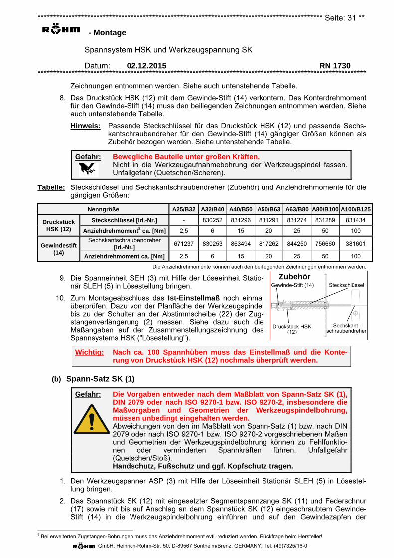
******************************************************************************************** Seite: 31 **
- Montage
Spannsystem HSK und Werkzeugspannung SK
Datum: 02.12.2015 RN 1730 **********************************************************************************************************
GmbH, Heinrich-Röhm-Str. 50, D-89567 Sontheim/Brenz, GERMANY, Tel. (49)7325/16-0
Sechskant-schraubendreher
Zubehör Steckschlüssel Gewinde-Stift (14)
Druckstück HSK (12)
Zeichnungen entnommen werden. Siehe auch untenstehende Tabelle.
8. Das Druckstück HSK (12) mit dem Gewinde-Stift (14) verkontern. Das Konterdrehmoment für den Gewinde-Stift (14) muss den beiliegenden Zeichnungen entnommen werden. Siehe auch untenstehende Tabelle.
Hinweis: Passende Steckschlüssel für das Druckstück HSK (12) und passende Sechs-kantschraubendreher für den Gewinde-Stift (14) gängiger Größen können als Zubehör bezogen werden. Siehe untenstehende Tabelle.
Gefahr: Bewegliche Bauteile unter großen Kräften. Nicht in die Werkzeugaufnahmebohrung der Werkzeugspindel fassen.
Unfallgefahr (Quetschen/Scheren).
Tabelle: Steckschlüssel und Sechskantschraubendreher (Zubehör) und Anziehdrehmomente für die gängigen Größen:
Nenngröße A25/B32 A32/B40 A40/B50 A50/B63 A63/B80 A80/B100 A100/B125
Druckstück HSK (12)
Steckschlüssel [Id.-Nr.] - 830252 831296 831291 831274 831289 831434
Anziehdrehmoment8 ca. [Nm] 2,5 6 15 20 25 50 100
Gewindestift (14)
Sechskantschraubendreher [Id.-Nr.]
671237 830253 863494 817262 844250 756660 381601
Anziehdrehmoment ca. [Nm] 2,5 6 15 20 25 50 100
Die Anziehdrehmomente können auch den beiliegenden Zeichnungen entnommen werden.
9. Die Spanneinheit SEH (3) mit Hilfe der Löseeinheit Statio-när SLEH (5) in Lösestellung bringen.
10. Zum Montageabschluss das Ist-Einstellmaß noch einmal überprüfen. Dazu von der Planfläche der Werkzeugspindel bis zu der Schulter an der Abstimmscheibe (22) der Zug-stangenverlängerung (2) messen. Siehe dazu auch die Maßangaben auf der Zusammenstellungszeichnung des Spannsystems HSK ("Lösestellung").
Wichtig: Nach ca. 100 Spannhüben muss das Einstellmaß und die Konte-rung von Druckstück HSK (12) nochmals überprüft werden.
(b) Spann-Satz SK (1)
Gefahr: Die Vorgaben entweder nach dem Maßblatt von Spann-Satz SK (1), DIN 2079 oder nach ISO 9270-1 bzw. ISO 9270-2, insbesondere die Maßvorgaben und Geometrien der Werkzeugspindelbohrung, müssen unbedingt eingehalten werden.
Abweichungen von den im Maßblatt von Spann-Satz (1) bzw. nach DIN 2079 oder nach ISO 9270-1 bzw. ISO 9270-2 vorgeschriebenen Maßen und Geometrien der Werkzeugspindelbohrung können zu Fehlfunktio-nen oder verminderten Spannkräften führen. Unfallgefahr (Quetschen/Stoß).
Handschutz, Fußschutz und ggf. Kopfschutz tragen.
1. Den Werkzeugspanner ASP (3) mit Hilfe der Löseeinheit Stationär SLEH (5) in Lösestel-lung bringen.
2. Das Spannstück SK (12) mit eingesetzter Segmentspannzange SK (11) und Federschnur (17) sowie mit bis auf Anschlag an dem Spannstück SK (12) eingeschraubtem Gewinde-Stift (14) in die Werkzeugspindelbohrung einführen und auf den Gewindezapfen der
8 Bei erweiterten Zugstangen-Bohrungen muss das Anziehdrehmoment evtl. reduziert werden. Rückfrage beim Hersteller!
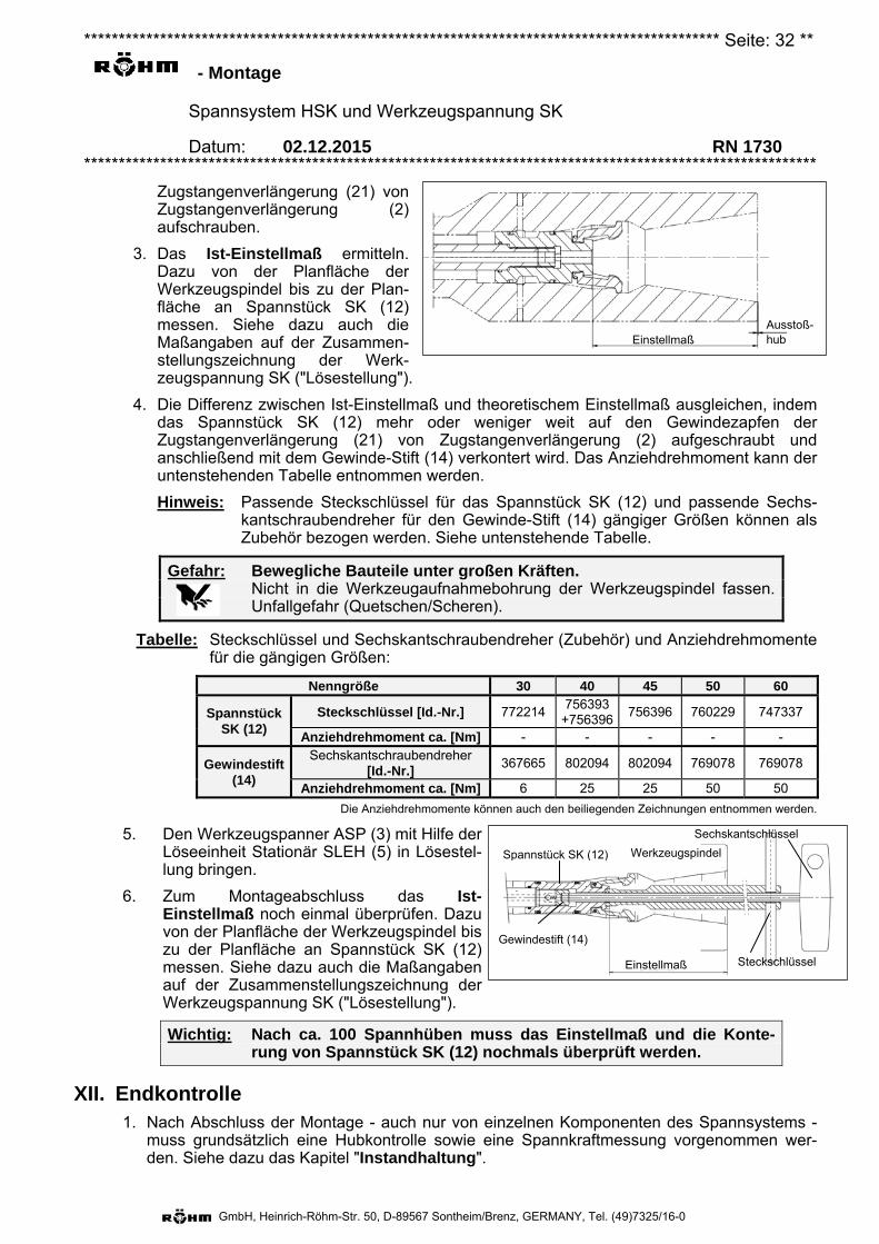
******************************************************************************************** Seite: 32 **
- Montage
Spannsystem HSK und Werkzeugspannung SK
Datum: 02.12.2015 RN 1730 **********************************************************************************************************
GmbH, Heinrich-Röhm-Str. 50, D-89567 Sontheim/Brenz, GERMANY, Tel. (49)7325/16-0
Einstellmaß Ausstoß-hub
Einstellmaß
Spannstück SK (12)
Gewindestift (14)
Steckschlüssel
Sechskantschlüssel
Werkzeugspindel
Zugstangenverlängerung (21) von Zugstangenverlängerung (2) aufschrauben.
3. Das Ist-Einstellmaß ermitteln. Dazu von der Planfläche der Werkzeugspindel bis zu der Plan-fläche an Spannstück SK (12) messen. Siehe dazu auch die Maßangaben auf der Zusammen-stellungszeichnung der Werk-zeugspannung SK ("Lösestellung").
4. Die Differenz zwischen Ist-Einstellmaß und theoretischem Einstellmaß ausgleichen, indem das Spannstück SK (12) mehr oder weniger weit auf den Gewindezapfen der Zugstangenverlängerung (21) von Zugstangenverlängerung (2) aufgeschraubt und anschließend mit dem Gewinde-Stift (14) verkontert wird. Das Anziehdrehmoment kann der untenstehenden Tabelle entnommen werden.
Hinweis: Passende Steckschlüssel für das Spannstück SK (12) und passende Sechs-kantschraubendreher für den Gewinde-Stift (14) gängiger Größen können als Zubehör bezogen werden. Siehe untenstehende Tabelle.
Gefahr: Bewegliche Bauteile unter großen Kräften. Nicht in die Werkzeugaufnahmebohrung der Werkzeugspindel fassen.
Unfallgefahr (Quetschen/Scheren).
Tabelle: Steckschlüssel und Sechskantschraubendreher (Zubehör) und Anziehdrehmomente für die gängigen Größen:
Nenngröße 30 40 45 50 60
Spannstück SK (12)
Steckschlüssel [Id.-Nr.] 772214 756393
+756396 756396 760229 747337
Anziehdrehmoment ca. [Nm] - - - - -
Gewindestift (14)
Sechskantschraubendreher [Id.-Nr.]
367665 802094 802094 769078 769078
Anziehdrehmoment ca. [Nm] 6 25 25 50 50 Die Anziehdrehmomente können auch den beiliegenden Zeichnungen entnommen werden.
5. Den Werkzeugspanner ASP (3) mit Hilfe der Löseeinheit Stationär SLEH (5) in Lösestel-lung bringen.
6. Zum Montageabschluss das Ist-Einstellmaß noch einmal überprüfen. Dazu von der Planfläche der Werkzeugspindel bis zu der Planfläche an Spannstück SK (12) messen. Siehe dazu auch die Maßangaben auf der Zusammenstellungszeichnung der Werkzeugspannung SK ("Lösestellung").
Wichtig: Nach ca. 100 Spannhüben muss das Einstellmaß und die Konte-rung von Spannstück SK (12) nochmals überprüft werden.
XII. Endkontrolle 1. Nach Abschluss der Montage - auch nur von einzelnen Komponenten des Spannsystems -
muss grundsätzlich eine Hubkontrolle sowie eine Spannkraftmessung vorgenommen wer-den. Siehe dazu das Kapitel "Instandhaltung".
******************************************************************************************** Seite: 33 **
- Demontage
Spannsystem HSK und Werkzeugspannung SK
Datum: 02.12.2015 RN 1730 **********************************************************************************************************
GmbH, Heinrich-Röhm-Str. 50, D-89567 Sontheim/Brenz, GERMANY, Tel. (49)7325/16-0
I. Personalqualifikation Die Demontage von Spannsystem HSK bzw. Werkzeugspanner SK aus der Werkzeugspindel darf nur durch ausgebildetes Fachpersonal des Herstellers der Werkzeugspindel, der Ma-schine oder des Spannsystems ausgeführt werden, das aufgrund seiner fachlichen Ausbildung mit den übertragenen Arbeiten sowie den möglichen Gefahren vertraut und in der Lage ist, diese durch geeignete Sicherheitsmaßnahmen zu minimieren.
II. Persönliche Schutzausrüstung 1. Folgende persönliche Schutzausrüstung muss getragen werden:
Kopfschutz.
Handschutz.
Augenschutz.
Fußschutz.
Warnung: Scharfkantige Bauteile können Schnittverletzungen verursachen. Gliedmaßen von scharfkantigen Bauteilen fernhalten. Handschutz benutzen.
III. Drücke 1. Während der gesamten Demontage muss jeglicher Betriebs- und Betätigungsdruck abgestellt
sein.
IV. Demontage Spann-Satz
(a) Spann-Satz HSK (1)
1. Die Spanneinheit SEH (3) mit Hilfe der Löseeinheit Stationär SLEH (5) in Endstellung (Spannstellung ohne Werkzeug bzw. leer durchgespannte Stellung) bringen.
2. Den Gewinde-Stift (14) von Spann-Satz HSK (1) um 2 - 3 Umdrehungen lösen.
3. Das Druckstück HSK (12) von Spann-Satz HSK (1) von der Zugstangenverlängerung (21) von Zugstangenverlängerung (2) herunterschrauben und nach vorn aus der Werkzeugspin-del herausziehen.
Hinweis: Informationen zu passendem Steckschlüssel für Druckstück HSK (12) und Sechskantschraubendreher für Gewinde-Stift (14) siehe im Kapitel "Montage" unter "Spann-Satz HSK (1)"
4. Die flexible Segmentspannzange HSK (11) von Spann-Satz HSK (1) aus der Ringnut der Ar-beitspindel herausnehmen.
(b) Spann-Satz SK (1)
1. Die Werkzeugspanner ASP (3) mit Hilfe der Löseeinheit Stationär SLEH (5) in Endstellung (Spannstellung ohne Werkzeug bzw. leer durchgespannte Stellung) bringen.
2. Den Gewinde-Stift (14) von Spann-Satz SK (1) um 2 - 3 Umdrehungen lösen.
3. Das Spannstück SK (12) von Spann-Satz SK (1) vom Gewindezapfen der Zugstangenver-längerung (21) von Zugstangenverlängerung (2) herunterschrauben und zusammen mit dem Gewinde-Stift (14), der Segmentspannzange SK (11) und der Federschnur (17) nach vorn aus der Werkzeugspindel herausziehen.
Hinweis: Informationen zu passendem Steckschlüssel für Spannstück SK (12) und Sechs-kantschraubendreher für Gewinde-Stift (14) siehe im Kapitel "Montage" unter "Spann-Satz SK (1)"

******************************************************************************************** Seite: 34 **
- Demontage
Spannsystem HSK und Werkzeugspannung SK
Datum: 02.12.2015 RN 1730 **********************************************************************************************************
GmbH, Heinrich-Röhm-Str. 50, D-89567 Sontheim/Brenz, GERMANY, Tel. (49)7325/16-0
V. Demontage Kühlmittel-Drehdurchführung (6) 1. Sämtliche Mediendrücke an die Kühlmittel-Drehdurchführung (6) abstellen und die Drucklei-
tungen aktiv entlasten (belüften).
2. Die Anschlussleitungen bei der Demontage der Kühlmittel-Drehdurchführung (6) in diese ein-geschraubt lassen.
3. Die Demontage der Kühlmittel-Drehdurchführung (6) selbst ist entweder der entsprechenden der beiliegenden Anleitungen zu entnehmen oder erfolgt in umgekehrter Reihenfolge der Mon-tage:
ROTOFLUX Bedienungsanleitung RN 1727 "Allgemeine Betriebsanweisung
Kühlmittel-Drehdurchführung "ROTOFLUX".
"ROTOFLUX Montage- und Einlaufanweisung" (englisch/italienisch).
DEUBLIN "Betriebsanleitung 040-555x DEUBLIN".
"DEUBLIN Installation 040-505".
GAT "GAT Rotodisk Betriebsanleitung".
Warnung: Unter hohem Druck austretende Flüssigkeiten oder Gase können vor allem im Gesichtsbereich schwere Verletzungen und/oder evtl. Verbrühungen verursachen.
Vor der Demontage die Drucklosigkeit der Druckanschlüsse und deren Leitungen kontrollieren. Aktiv belüften.
Augenschutz benutzen!
VI. Demontage Löseeinheit Stationär SLEH (5) 1. Sämtliche Mediendrücke an die Löseeinheit Stationär SLEH (5) abstellen und die Druckleitun-
gen aktiv entlasten (belüften).
2. Die Anschlussleitungen aus dem Aufnahmedeckel (53) der Löseeinheit Stationär SLEH (5) herausschrauben.
Warnung: Unter hohem Druck austretende Flüssigkeiten oder Gase können vor allem im Gesichtsbereich schwere Verletzungen und/oder evtl. Verbrühungen verursachen.
Vor der Demontage die Drucklosigkeit der Druckanschlüsse und deren Leitungen kontrollieren. Aktiv belüften.
Augenschutz benutzen!
3. Die Anschlussgewinde an Aufnahmedeckel (53) mit Stopfen verschließen.
4. Die Zylinderschrauben (54) aus dem stationär an dem Werkzeugspindelgehäuse befestigten Adapterflansch herausschrauben und zusammen mit diesen die komplette Löseeinheit Statio-när SLEH (5) nach hinten herunternehmen.
Achtung: RUTSCHGEFAHR! Ölaustritt aus den Löseeinheit Stationär SLEH (5) und/oder aus den An-
schlussleitungen. Auffangvorrichtungen verwenden und sachgerecht entsorgen.
Kühlmittel-Dreh-durchführung DEUBLIN
Kühlmittel-Dreh-durchführung GAT
Kühlmittel-Dreh-durchführung
ROTOFLUX
******************************************************************************************** Seite: 35 **
- Demontage
Spannsystem HSK und Werkzeugspannung SK
Datum: 02.12.2015 RN 1730 **********************************************************************************************************
GmbH, Heinrich-Röhm-Str. 50, D-89567 Sontheim/Brenz, GERMANY, Tel. (49)7325/16-0
VII. Demontage Spanneinheit SEH (3) bzw. Werkzeugspanner ASP (3) + Zugstangenverlängerung (2)
Gefahr: Die Spanneinheit SEH (3) bzw. Werkzeugspanner ASP (3) und die Zugstangenverlängerung (2) dürfen nur vom Hersteller auseinan-dergeschraubt werden!
Die Spanneinheit SEH (3) bzw. der Werkzeugspanner ASP (3) darf nur vom Hersteller zerlegt werden!
Spanneinheit SEH (3)
1. Die Abstimmscheibe (22) der Zugstangenverlängerung (2) nach vorn aus der Werkzeugspin-delbohrung herausnehmen.
Hinweis: Der Abstimmscheibe (22) der Zugstangenverlängerung (2) ist mit mehreren Ge-windebohrungen versehen. Mit Hilfe dieser Gewinde und passenden langen Schrauben kann die Montage/Demontage der Abstimmscheibe (22) der Zugstan-genverlängerung (2) vereinfacht werden.
2. Die Spanneinheit SEH (3) mit der verschraubten Zugstangenverlängerung (2) nach hinten aus der Werkzeugspindelbohrung herausziehen.
3. Die Abstimmscheibe (22) der Zugstangenverlängerung (2) wieder auf deren Zugstangenver-längerung (21) aufschieben.
4. Die Spanneinheit SEH (3) und die Zugstangenverlängerung (2) miteinander verschraubt auf-bewahren.
Vorsicht: Von vorgespannten elastischen Elementen herausgeschleuderte Teile können, vor allem im Gesichtsbereich, Verletzungen verursa-chen.
Augenschutz benutzen! Die Spanneinheit SEH (3) nicht zerlegen!
Werkzeugspanner ASP (3)
1. Den Werkzeugspanner ASP (3) mit der verschraubten Zugstangenverlängerung (2) nach hin-ten aus der Werkzeugspindelbohrung herausziehen.
2. Die Werkzeugspanner ASP (3) und die Zugstangenverlängerung (2) miteinander verschraubt aufbewahren.
Vorsicht: Von vorgespannten elastischen Elementen herausgeschleuderte Teile können, vor allem im Gesichtsbereich, Verletzungen verursa-chen.
Augenschutz benutzen! Den Werkzeugspanner ASP (3) nicht zerle-gen!
******************************************************************************************** Seite: 36 **
- Instandhaltung
Spannsystem HSK und Werkzeugspannung SK
Datum: 02.12.2015 RN 1730 **********************************************************************************************************
GmbH, Heinrich-Röhm-Str. 50, D-89567 Sontheim/Brenz, GERMANY, Tel. (49)7325/16-0
Personalqualifikationen Zur Durchführung der im Zuge der Instandhaltungsmaßnahmen anfallenden Arbeiten sind unter-schiedliche Personalqualifikationen erforderlich. Diese sind in folgende Gruppen untergeteilt:
1. Qualifikationsgruppe 1 Unterwiesenes Personal: Die unterwiesene Person muss nachweislich in einer Unterweisung durch den Betreiber über die ihr übertragenen Aufgaben und möglichen Gefahren bei unsach-gemäßem Verhalten unterrichtet sein.
Übertragene Maßnahmen: – Inspektion (z. B. visuelle Kontrolle, Spannkraftkontrolle, Signalabgabe (Justierung) der Hub-
kontrollsensoren überprüfen, Dichtheitskontrollen). – Reinigung und Schmierung von Werkzeugspindelkonus bzw. Werkzeugschaft. – Einstellmaßkontrolle.
2. Qualifikationsgruppe 2 Ausgebildetes Fachpersonal des Herstellers von Werkzeugspindel, Maschine bzw. des Spannsystems oder des Betreibers: Fachpersonal, das aufgrund seiner fachlichen Ausbildung mit den übertragenen Arbeiten sowie den möglichen Gefahren vertraut und in der Lage ist, diese durch geeignete Sicherheitsmaßnahmen zu minimieren.
Übertragene Maßnahmen: – Alle Wartungs- und Instandsetzungsmaßnahmen am Spannsystem HSK bzw. Werkzeugspan-
ner SK, welche auf den Aus- und Einbau ganzer Gruppen beschränkt sind. Die mit der Span-neinheit SEH (3) bzw. dem Werkzeugspanner ASP (3) verschraubte Zugstangenverlängerung (2) gilt dabei als 1 Gruppe.
– Einstellmaß-Korrektur.
3. Qualifikationsgruppe 3 Ausgebildetes Fachpersonal des Spannsystem-Herstellers: Fachpersonal, das aufgrund sei-ner fachlichen Ausbildung mit den übertragenen Arbeiten sowie den möglichen Gefahren vertraut und in der Lage ist, diese durch geeignete Sicherheitsmaßnahmen zu minimieren.
Übertragene Maßnahmen: – Demontage von Zugstangenverlängerung (2) und Spanneinheit SEH (3) bzw. Werkzeugspan-
ner ASP (3). – Zerlegen der Spanneinheit SEH (3) bzw. des Werkzeugspanner ASP (3).
Persönliche Schutzausrüstung 1. Folgende persönliche Schutzausrüstung muss getragen werden:
Handschutz.
Kopfschutz
Augenschutz.
Drücke 1. Abgesehen zu Prüfzwecken muss während der Instandhaltungsmaßnahmen jeglicher Betäti-
gungsdruck abgestellt sein. Dies gilt insbesondere, wenn zu Instandhaltungszwecken in die Werk-zeugaufnahme gefasst werden muss.
Warnung: Unter hohem Druck austretende Flüssigkeiten oder Gase können vor allem im Gesichtsbereich schwere Verletzungen und/oder evtl. Verbrühungen verursachen.
Vor Instandhaltungsmaßnahmen die Drucklosigkeit der Druckanschlüs-se und deren Leitungen kontrollieren. Aktiv belüften.
Augenschutz benutzen!
******************************************************************************************** Seite: 37 **
- Instandhaltung
Spannsystem HSK und Werkzeugspannung SK
Datum: 02.12.2015 RN 1730 **********************************************************************************************************
GmbH, Heinrich-Röhm-Str. 50, D-89567 Sontheim/Brenz, GERMANY, Tel. (49)7325/16-0
Funktions- und Sicherheitsprüfung:
Warnung: Scharfkantige Bauteile können Schnittverletzungen verursachen. Gliedmaßen von scharfkantigen Bauteilen fernhalten. Handschutz benutzen.
Gefahr: Bewegliche Bauteile unter großen Kräften. Nicht in die Werkzeugaufnahmebohrung der Werkzeugspindel fassen.
Unfallgefahr (Quetschen/Scheren). Handschutz benutzen.
Wöchentlich oder nach 75 Betriebsstunden9
1. Den Spann-Satz HSK (1) bzw. Spann-Satz SK (1) visuell überprüfen (Qualifikationsgruppe 1): Spannbewegung Justierung (Signalabgabe) der Hubkontrollsensoren über dem Hubkontrollring (32) von Span-
neinheit SEH (3) oder Werkzeugspanner ASP (3) überprüfen. Beschädigungen Dichtheitskontrolle Löseeinheit stationär SLEH (5) und Kühlmittel-Drehdurchführung (6). Verschmutzung - ggf. mit Reinigung und Schmierung von Werkzeugspindelkonus bzw. Werk-
zeugschaft (auch O-Ring (15) von Spannsatz HSK (1)) Entfettung
Bei Hubkontrollfehler: die Justierung der Hubkontrollsensoren entsprechend deren Betriebsanlei-
tung optimieren. Beschädigungen: gesamten Spann-Satz HSK (1) bzw. Spannsatz SK (1) austauschen (Quali-
fikationsgruppe 2). Öl/Kühlmittelaustritt: Löseeinheit stationär SLEH (5) demontieren Leckageursache beheben. Evtl.
neue Dichtungen einsetzen. Dann die Löseeinheit stationär SLEH (5) wieder montieren. Bei Kühlmittel-Drehdurchführung (6) diese ersetzen.
Verschmutzung: Spann-Satz HSK (1) bzw. Spannsatz SK (1) ausbauen und zusammen mit der Spindelinnenkontur reinigen (Qualifikationsgruppe 2). Hinweis beach-ten!
Entfettung: Grund der Entfettung feststellen bzw. beheben (z. B. defekte Dichtungen, ungeeignetes Kühlschmiermittel, Auswaschung in unbestücktem Zustand. Segmentspannzange HSK (11) bzw. Segmentspannzange SK (11) nach-schmieren (in eingebautem Zustand z. B. mit Hilfe einer Bürste). Schmier-stoffe siehe unten (Qualifikationsgruppe 2).
Hinweis: Die Verwendung von Druckluft von außen zur allgemeinen Reinigung von Spannsys-tem HSK / Werkzeugspannung SK ist nicht zulässig.
Monatlich oder nach 300 Betriebsstunden9
1. Das Einstellmaß von Druckstück HSK (12) bzw. Spannstück SK (12) kontrollieren (Qualifika-tionsgruppe 1). Bei Einstellmaßfehler: Einstellmaß korrigieren bzw. neu einstellen (Qualifikationsgruppe 2). Sie-he Kapitel "Montage" → "Montage Spann-Satz" → "Spann-Satz HSK (1)" oder "Spann-Satz SK (1)"
2. Die Spannkraft bzw. Einzugskraft messen. Dazu muss ein zugelassenes Spannkraftmessgerät10 verwendet werden.
9 Was zuerst eintrifft. 10 Z. B. RÖHM Spannkraftmessgerät F-SENSO SPINDLE 10 - 100 kN, Id.-Nr. 1255729. mit Adapter HSK 100 Id.-Nr. 1255741 bzw. Adapter SK 50 Id.-Nr. 1255745
******************************************************************************************** Seite: 38 **
- Instandhaltung
Spannsystem HSK und Werkzeugspannung SK
Datum: 02.12.2015 RN 1730 **********************************************************************************************************
GmbH, Heinrich-Röhm-Str. 50, D-89567 Sontheim/Brenz, GERMANY, Tel. (49)7325/16-0
HSK-Spannsystem: Bei einem Messwert unterhalb den in DIN 69893 / DIN 69063 angegebenen Werten11, muss fol-gender Maßnahmenkatalog der Reihe nach so lange abgearbeitet werden, bis der Messwert min-destens dem Sollwert entspricht (Qualifikationsgruppe 2): 1. Segmentspannzange HSK (11) nachfetten und die Spannkraft erneut messen.2. Spann-Satz HSK (1) austauschen und die Spannkraft erneut messen.3. HSK-Spannsystem außer Betrieb nehmen und komplett ersetzen.
Hinweis: Siehe auch Kapitel "Bestimmungsgemäße Verwendung + Beschreibung" -> "Au-ßerbetriebnahme / Stillsetzen".
SK-Spannsystem: Bei einem Messwert unterhalb den angegebenen Mindest-Werten12, muss folgender Maßnahmen-katalog der Reihe nach so lange abgearbeitet werden, bis der Messwert mindestens dem Sollwert entspricht (Qualifikationsgruppe 2): 1. Segmentspannzange SK (11) nachfetten und die Einzugskraft erneut messen.2. Spann-Satz SK (1) austauschen und die Einzugskraft erneut messen.3. Werkzeugspannung SK außer Betrieb nehmen und komplett ersetzen.
Hinweis: Siehe auch Kapitel "Bestimmungsgemäße Verwendung + Beschreibung" -> "Au-ßerbetriebnahme / Stillsetzen".
Instandhaltung:
Jährlich oder nach 500.000 Werkzeugwechseln13
HSK-Spannsystem und Werkzeugspanner SK: 1. Den O-Ring (15) von Spann-Satz HSK (1) bzw. Spann-Satz SK (1) erneuern (Qualifikations-
gruppe 2).
Schmiermittelempfehlung für Spann-Satz HSK (1):
1. Fettpasten:
GLEITMETALL-PASTE TECHNO-SERVICE GmbH 70-85: Detmolder Str. 515
33605 Bielefeld
MOLYKOTE TP42 DOW CORNING GMBH Pelkovenstr. 152 80992 München
FETT-PASTE TECHNO-SERVICE GMBH METAFLUX 70-8508 Detmolder Str. 515
33605 Bielefeld
2. Schmier-Sprays:
GLEITMETALL-SPRAY TECHNO-SERVICE GMBH METAFLUX 70-81 Detmolder Str. 515
33605 Bielefeld
FIN GREASE + INTERFLON DEUTSCHLAND GMBH TEFLON SPRAY Herrenpfad-Süd 6
41334 Nettetal
11 Siehe Tabelle in Kapitel "Bestimmungsgemäße Verwendung + Beschreibung" -> "Grenzwerte". 12 Siehe Tabelle in Kapitel "Bestimmungsgemäße Verwendung + Beschreibung" -> "Grenzwerte". 13 Was zuerst eintrifft.
******************************************************************************************** Seite: 39 **
- Instandhaltung
Spannsystem HSK und Werkzeugspannung SK
Datum: 02.12.2015 RN 1730 **********************************************************************************************************
GmbH, Heinrich-Röhm-Str. 50, D-89567 Sontheim/Brenz, GERMANY, Tel. (49)7325/16-0
Instandsetzung Austausch von Spannsatz HSK (1) bzw. Spannsatz SK (1) durch Personal der Qualifikations-
gruppe 2.
Von Spannsystem HSK bzw. Werkzeugspanner SK mit Austausch von Einzelbauteilen durch Per-sonal der Qualifikationsgruppe 3.
Der Löseeinheit stationär (5) durch Personal der Qualifikationsgruppe 3.
Der Kühlmittel-Drehdurchführung (6) durch Personal der Qualifikationsgruppe 3 oder durch den Lieferant der Kühlmittel-Drehdurchführung (6).
Um im Störfall längere Ausfallzeiten zu vermeiden empfiehlt es sich, stets jeweils einen Satz der auf den Stücklisten gekennzeichneten Verschleißteile auf Lager zu legen.
Weiterhin werden auf Anfrage Reparatur-Spannsätze und Ersatzteil-Sätze mit entsprechenden Austauschanleitungen zur Verfügung gestellt.
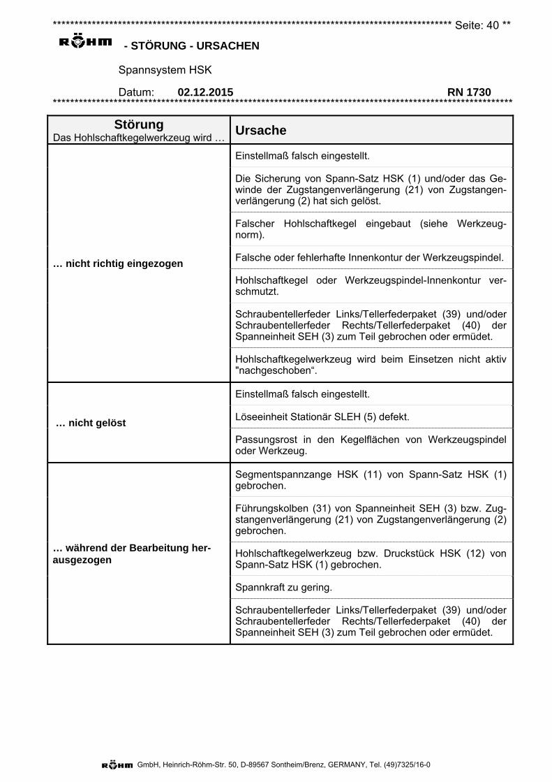
******************************************************************************************** Seite: 40 **
- STÖRUNG - URSACHEN
Spannsystem HSK
Datum: 02.12.2015 RN 1730 **********************************************************************************************************
GmbH, Heinrich-Röhm-Str. 50, D-89567 Sontheim/Brenz, GERMANY, Tel. (49)7325/16-0
Störung Das Hohlschaftkegelwerkzeug wird …
Ursache
… nicht richtig eingezogen
Einstellmaß falsch eingestellt.
Die Sicherung von Spann-Satz HSK (1) und/oder das Ge-winde der Zugstangenverlängerung (21) von Zugstangen-verlängerung (2) hat sich gelöst.
Falscher Hohlschaftkegel eingebaut (siehe Werkzeug-norm).
Falsche oder fehlerhafte Innenkontur der Werkzeugspindel.
Hohlschaftkegel oder Werkzeugspindel-Innenkontur ver-schmutzt.
Schraubentellerfeder Links/Tellerfederpaket (39) und/oder Schraubentellerfeder Rechts/Tellerfederpaket (40) der Spanneinheit SEH (3) zum Teil gebrochen oder ermüdet.
Hohlschaftkegelwerkzeug wird beim Einsetzen nicht aktiv "nachgeschoben“.
… nicht gelöst
Einstellmaß falsch eingestellt.
Löseeinheit Stationär SLEH (5) defekt.
Passungsrost in den Kegelflächen von Werkzeugspindel oder Werkzeug.
… während der Bearbeitung her-ausgezogen
Segmentspannzange HSK (11) von Spann-Satz HSK (1) gebrochen.
Führungskolben (31) von Spanneinheit SEH (3) bzw. Zug-stangenverlängerung (21) von Zugstangenverlängerung (2) gebrochen.
Hohlschaftkegelwerkzeug bzw. Druckstück HSK (12) von Spann-Satz HSK (1) gebrochen.
Spannkraft zu gering.
Schraubentellerfeder Links/Tellerfederpaket (39) und/oder Schraubentellerfeder Rechts/Tellerfederpaket (40) der Spanneinheit SEH (3) zum Teil gebrochen oder ermüdet.
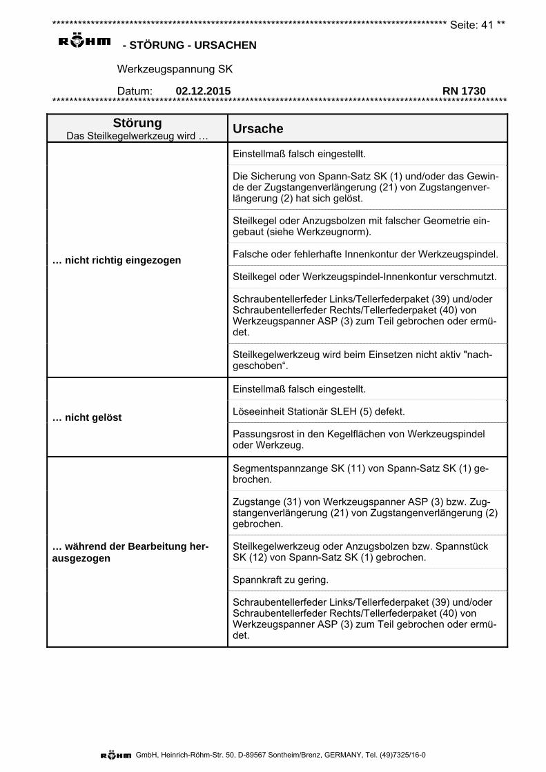
******************************************************************************************** Seite: 41 **
- STÖRUNG - URSACHEN
Werkzeugspannung SK
Datum: 02.12.2015 RN 1730 **********************************************************************************************************
GmbH, Heinrich-Röhm-Str. 50, D-89567 Sontheim/Brenz, GERMANY, Tel. (49)7325/16-0
Störung Das Steilkegelwerkzeug wird …
Ursache
… nicht richtig eingezogen
Einstellmaß falsch eingestellt.
Die Sicherung von Spann-Satz SK (1) und/oder das Gewin-de der Zugstangenverlängerung (21) von Zugstangenver-längerung (2) hat sich gelöst.
Steilkegel oder Anzugsbolzen mit falscher Geometrie ein-gebaut (siehe Werkzeugnorm).
Falsche oder fehlerhafte Innenkontur der Werkzeugspindel.
Steilkegel oder Werkzeugspindel-Innenkontur verschmutzt.
Schraubentellerfeder Links/Tellerfederpaket (39) und/oder Schraubentellerfeder Rechts/Tellerfederpaket (40) von Werkzeugspanner ASP (3) zum Teil gebrochen oder ermü-det.
Steilkegelwerkzeug wird beim Einsetzen nicht aktiv "nach-geschoben“.
… nicht gelöst
Einstellmaß falsch eingestellt.
Löseeinheit Stationär SLEH (5) defekt.
Passungsrost in den Kegelflächen von Werkzeugspindel oder Werkzeug.
… während der Bearbeitung her-ausgezogen
Segmentspannzange SK (11) von Spann-Satz SK (1) ge-brochen.
Zugstange (31) von Werkzeugspanner ASP (3) bzw. Zug-stangenverlängerung (21) von Zugstangenverlängerung (2) gebrochen.
Steilkegelwerkzeug oder Anzugsbolzen bzw. Spannstück SK (12) von Spann-Satz SK (1) gebrochen.
Spannkraft zu gering.
Schraubentellerfeder Links/Tellerfederpaket (39) und/oder Schraubentellerfeder Rechts/Tellerfederpaket (40) von Werkzeugspanner ASP (3) zum Teil gebrochen oder ermü-det.
******************************************************************************************** Seite: 42 **
- Ersatzteile
Spannsystem HSK und Werkzeugspannung SK
Datum: 02.12.2015 RN 1730 **********************************************************************************************************
GmbH, Heinrich-Röhm-Str. 50, D-89567 Sontheim/Brenz, GERMANY, Tel. (49)7325/16-0
Es wird darauf hingewiesen, dass ausschließlich ORIGINAL RÖHM-Ersatzteile bzw. Einbauteile von autorisierten Lieferanten der FA. RÖHM GmbH zu verwenden sind. Für alle Schäden, die durch die Verwendung von Fremdbauteilen entstehen, erlischt jegliche Haftung der FA. RÖHM GmbH.
Hinweis: Um Nachbestellungen von Ersatzteilen bzw. Einzelteilen reibungslos durchführen zu kön-nen, ist die Angabe der auf der Baugruppe eingravierten 6-stelligen Ident-Nummer und - wenn vorhanden - die Fabrikationsnummer erforderlich. Diese besteht aus einem Buch-staben gefolgt von 2 Ziffern und evtl. einer laufenden Nummer, angebracht entweder auf dem Typenschild oder in unmittelbarer Nähe zur Ident-Nr.
Herstelleranschrift: Firma
RÖHM GmbH Heinrich-Röhm-Str. 50 89567 Sontheim /Brenz GERMANY
******************************************************************************************** Seite: 43 **
- Gewährleistungsausschluss
Spannsystem HSK und Werkzeugspannung SK
Datum: 02.12.2015 RN 1730 **********************************************************************************************************
GmbH, Heinrich-Röhm-Str. 50, D-89567 Sontheim/Brenz, GERMANY, Tel. (49)7325/16-0
Die Gewährleistung des Verkäufers erstreckt sich nicht auf Schäden oder Mängel,
1. verursacht durch den Betreiber durch Nichterfüllung der schriftlichen Anweisungen des Verkäufers in Bezug auf die Inbetriebnahme (z. B. mangelhafte Bau- und Montagearbeiten) den Betrieb und die Wartung der Ausrüstung (sofern diese Wartung nicht vertraglich vom Hersteller übernommen wurde).
2. verursacht durch dem Hersteller unbekannte technische Betriebsbedingungen (z. B. chemischer oder elektrolytischer Einflüsse) und/oder Maschinendaten.
3. verursacht durch natürlichen Verschleiß.
4. verursacht durch Einwirkung von höherer Gewalt.
5. verursacht durch Fehlbedienung jeglicher Art oder verursacht durch nicht sachgemäßen Einsatz oder Betrieb der Spanneinrichtung oder Teile derselben. Dazu zählt auch die Belastung jenseits der angegebenen Belastungsgrenzen (z. B. Drehzahl, Druck, Kraft usw.).
6. welche nicht von uns zu vertreten sind. Das umfasst auch Schäden, welche entstehen, wenn der Kunde oder Dritte ohne die vorherige schriftliche Zustimmung des Herstellers Änderungen oder Reparaturen an dessen Leistungen/Produkten vornehmen. Davon ausgenommen sind Schäden oder Mängel, welche nachweislich nicht durch diese Änderungen oder Reparaturen eingetreten sind.
7. welche durch Einsatz der Anlage oder Teile derselben unter geänderten Betriebsbedingungen (z. B. Werkstoffe, Werkzeuge, Schnittparameter, Programme etc.) erfolgen, insbesondere ohne Rücksprache und schriftliche Freigabe durch den Verkäufer bzw. Hersteller.
8. welche auf geänderte Umgebungsbedingungen zurückzuführen sind.
******************************************************************************************** Seite: 44 **
- Entsorgung
Spannsystem HSK und Werkzeugspannung SK
Datum: 02.12.2015 RN 1730 **********************************************************************************************************
GmbH, Heinrich-Röhm-Str. 50, D-89567 Sontheim/Brenz, GERMANY, Tel. (49)7325/16-0
Materialien
Die bei Spannsystem HSK und Werkzeugspannung SK überwiegend verwendeten Stoffe:
Material verwendet für Gewichtsanteile in % ca.
Stahl Hauptkomponenten 100
Fett, Öl, organische COH-Gruppen Betriebsstoff, Schmierung Spuren
Silikon / Gummi (schwarz) Distanzhaltung der Segment-spannzange HSK (11) von Spann-satz HSK (1)
Spuren
NBR (PERBUNAN®, Nitril-Butadien-Kautschuk,
schwarz) Dichtungen (O-Ringe, Dichtman-schetten, Usitringe, Abstreifer) Spuren
FPM/FKM (VITON®, Fluorkautschuk, braun) O-Ringe Spuren
PTFE (TURCON®, Polytretraflourethylen,
weiß/hellgrau) Dichtungen (Stützringe) Spuren
H-PU (Thermoplastisches Polyurethan, rot), PA (Polyamid, naturweiß) oder POM (Po-lyoxymethylen, weiß)
Stangen- und Kolben-Dichtungen Spuren
Hinweis: Die bei den Kunststoffen angegebenen Farben sind nicht verbindlich. Je nach Hersteller können andere Farben Verwendung finden. Stückliste beachten.
Entsorgungshinweise
Personalqualifikationen
Zur Durchführung der im Zuge der Entsorgung anfallenden Arbeiten (Demontage und ggf. Zerlegen) sind unterschiedliche Personalqualifikationen erforderlich. Diese sind in folgende Gruppen unterge-teilt:
Qualifikationsgruppe 2 Ausgebildetes Fachpersonal des Herstellers von Werkzeugspindel, Maschine bzw. des Spann-systems: Fachpersonal, das aufgrund seiner fachlichen Ausbildung mit den übertragenen Arbeiten sowie den möglichen Gefahren vertraut und in der Lage ist, diese durch geeignete Sicherheitsmaß-nahmen zu minimieren.
Übertragene Maßnahmen: – Ausbau ganzer Gruppen aus der Werkzeugspindel. Die mit der Spanneinheit SEH (3) bzw. dem
Werkzeugspanner ASP (3) verschraubte Zugstangenverlängerung (2) gilt dabei als 1 Gruppe.
Qualifikationsgruppe 3 Ausgebildetes Fachpersonal des Spannsystem-Herstellers: Fachpersonal, das aufgrund seiner fachlichen Ausbildung mit den übertragenen Arbeiten sowie den möglichen Gefahren vertraut und in der Lage ist, diese durch geeignete Sicherheitsmaßnahmen zu minimieren.
Übertragene Maßnahmen: – Trennen von Zugstangenverlängerung (2) und Spanneinheit SEH (3) bzw. Werkzeugspanner
ASP (3). – Zerlegen der Spanneinheit SEH (3) bzw. von Werkzeugspanner ASP (3).
Persönliche Schutzausrüstung
1. Folgende persönliche Schutzausrüstung muss getragen werden:
Fußschutz.
Handschutz.
******************************************************************************************** Seite: 45 **
- Entsorgung
Spannsystem HSK und Werkzeugspannung SK
Datum: 02.12.2015 RN 1730 **********************************************************************************************************
GmbH, Heinrich-Röhm-Str. 50, D-89567 Sontheim/Brenz, GERMANY, Tel. (49)7325/16-0
Kopfschutz.
Augenschutz.
Maßnahmen (Qualifikationsgruppe 2)
1. Das Spannsystem HSK bzw. die Werkzeugspannung SK demontieren. Siehe dazu das Kapitel "Demontage".
Wichtig: Die Spanneinheit SEH (3) bzw. der Werkzeugspanner ASP (3) und die Zugstangenver-längerung (2) dürfen dabei nicht auseinandergeschraubt werden.
2. Vor der Entsorgung muss die Löseeinheit Stationär SLEH (5) entleert werden. Das anfallende Hydrauliköl muss den lokalen Vorschriften entsprechend mit dem Altöl entsorgt oder wiederver-wendet werden.
3. Sofern die eingebauten Dichtungen (diverse Kunststoffe) nicht getrennt entsorgt werden müssen, können alle Komponenten von Spannsystem HSK oder Werkzeugspannung SK im gewöhnli-chen Stahlschrott entsorgt werden.
Gefahr: Die Spanneinheit SEH (3) bzw. der Werkzeugspanner ASP (3) und die Zugstangenverlängerung (2) dürfen nur vom Hersteller ausei-nandergeschraubt werden!
Die Spanneinheit SEH (3) bzw. der Werkzeugspanner ASP (3) darf nur vom Hersteller zerlegt werden!
Maßnahmen (Qualifikationsgruppe 3)
1. Das Spannsystem HSK bzw. die Werkzeugspannung SK muss bereits demontiert sein. Siehe da-zu auch das Kapitel "Demontage".
2. Sollten aufgrund eventueller lokal geltenden Vorschriften selbst kleinste Spuren fremder (z. B. un-magnetischer) Stoffe getrennt werden müssen, dann muss das gesamte, entleerte Spannsystem HSK oder die gesamte, entleerte Werkzeugspannung SK vor der Entsorgung werkstoffdifferen-ziert zerlegt und nach den verwendeten Materialien (siehe Liste oben bzw. Stückliste) getrennt entsorgt werden.
3. Wird das Spannsystem HSK oder die Werkzeugspannung SK zerlegt, sind einzelne Punkte aus Kapitel "Allgemeine Gefahrenhinweise" zu beachten (Qualifikation des Bedieners, Verletzungs-gefahren (teilweise), Umweltgefahren).
KOB Sontheim, Ausgabedatum: 28.06.2016
Ausstoßhub
GmbH, Heinrich-Röhm-Str. 50, D-89567 Sontheim/Brenz, GERMANY, Tel. (49)7325/16-0
RN 1730
Translation of the original operating instructions
RÖHM – HSK clamping system SK tool clamping system
Stationary unclamping unit consisting of:
HSK / SK clamping set Draw bar extension SEH clamping unit or ASP tool clamp SLEH stationary unclamping unit Coolant rotary supply unit
Contents Page
The most important HSK components (schematic diagrams) 2 The most important SK components (schematic diagrams) 3 Terms 4Intended use + description 6 General warnings 18 Operation 22Assembly 26Dismounting 33Maintenance 36Failure – Causes 40 Spare parts 42 Warranty exclusion 43 Disposal 44
Drawing(s) and piece list(s) (also of subassemblies) Attachment "Rotoflux installation and run-in instructions" (English/Italian) Attachment Operating instructions RN 1727 (for ROTOFLUX) AttachmentDEUBLIN 040-555x operating manual Attachment DEUBLIN installation 040-505 Attachment GAT ROTODISK operating instructions Attachment
Date of issue: (German original) 02.12.2015
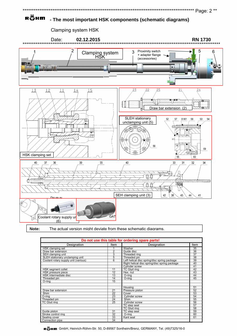
******************************************************************************************** Page: 2 **
- The most important HSK components (schematic diagrams)
Clamping system HSK
Date: 02.12.2015 RN 1730 **********************************************************************************************************
GmbH, Heinrich-Röhm-Str. 50, D-89567 Sontheim/Brenz, GERMANY, Tel. (49)7325/16-0
Do not use this table for ordering spare parts! Designation Item Designation Item
HSK clamping set 1 Washer 35 Draw bar extension 2 Guide disc 36 SEH clamping unit 3 Threaded ring 37 SLEH stationary unclamping unit 5 Threaded pin 38 Coolant rotary supply unit (various) 6 Left helical disc spring/disc spring package 39 Right helical disc spring/disc spring package 40 Cylinder screw 41 HSK segment collet 11 TC Glyd ring 42 HSK pressure piece 12 Hex. nut 43 HSK intermediate disc 13 O-ring 44 Threaded pin 14 O-ring 45 O-ring 15 Housing 51 Draw bar extension 21 Pressure piston 52 Shim 22 Cover 53 O-ring 23 Cylinder screw 54 Threaded pin 24 Shim 55 TC Glyd ring 25 Cylinder screw 56 TC step seal 57 TC Glyd ring 58 Guide piston 31 TC step seal 59 Stroke control ring 32 O-ring 60 Sealing cover 33 Kant seal 61 Connection pipe 34
HSK clamping set
Draw bar extension (2)
SEH clamping unit (3)
Note: The actual version might deviate from these schematic diagrams.
ROTOFLUX
DEUBLIN
Coolant rotary supply unit (6)
GAT
SLEH stationary unclamping unit (5)
Clamping system HSK
5 6 3 2 1 Proximity switch + adapter flange (accessories)
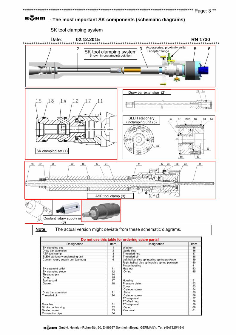
******************************************************************************************** Page: 3 **
- The most important SK components (schematic diagrams)
SK tool clamping system
Date: 02.12.2015 RN 1730 **********************************************************************************************************
GmbH, Heinrich-Röhm-Str. 50, D-89567 Sontheim/Brenz, GERMANY, Tel. (49)7325/16-0
Do not use this table for ordering spare parts! Designation Item Designation Item
SK clamping set 1 Washer 35Draw bar extension 2 Guide disc 36 ASP tool clamp 3 Threaded ring 37SLEH stationary unclamping unit 5 Threaded pin 38Coolant rotary supply unit (various) 6 Left helical disc spring/disc spring package 39
Right helical disc spring/disc spring package 40Piston housing 41
SK segment collet 11 Hex. nut 43 SK clamping piece 12 O-ring 45Threaded pin 14O-ring 15Spring cord 17 Housing 51Gasket 18 Pressure piston 52
Cover 53Cylinder screw 54
Draw bar extension 21 Shim 55 Threaded pin 24 Cylinder screw 56
TC step seal 57 TC Glyd ring 58
Draw bar 31 TC step seal 59 Stroke control ring 32 O-ring 60Sealing cover 33 Kant seal 61Connection pipe 34
Accessories: proximity switch + adapter flange
Note: The actual version might deviate from these schematic diagrams.
Coolant rotary supply unit (6)
SLEH stationary unclamping unit (5)
SK clamping set (1)
Draw bar extension (2)
ASP tool clamp (3)
SK tool clamping system Shown in unclamping position
5 6 3 2 1
******************************************************************************************** Page: 4 **
- Terms
The HSK clamping system and SK tool clamping system
Date: 02.12.2015 RN 1730 **********************************************************************************************************
GmbH, Heinrich-Röhm-Str. 50, D-89567 Sontheim/Brenz, GERMANY, Tel. (49)7325/16-0
The following terms apply for using this document.
Actuating force Force which acts on the HSK clamping set (1) or on the HSK pressure piece (12) or on the SK clamping set (1) or on the SK clamping piece (12) in the clamping position.
Pulling-in force (a) HSK: The clamping force (see below, standardized term for HSK clamping system) is often
referred to as the "pull-in force", since this expression excellently describes the effect of the force.
(b) SK: In the case of the SK tool clamping system: Force at which the taper tool is pulledaxially into the tool spindle with its draw bolt by the SK segment collet (11).
Spring force Force, generated by the left helical disc spring/disc spring package (39) or right helical disc spring/disc spring package (40), and is dissipated with the clamping system
(a) HSK: to the guide piston (31).
(b) SK: via the wedge slide gear of the ASP tool clamp (3) to its draw bar (31).
HSK Clamping system for tools with a hollow shank taper, DIN 69893-1:2011-04 and VDMA 34181:2005-07, for installation in tool spindles in acc. with DIN 69063-1:2005-05.
Unclamping force Force required to safely unclamp the SEH clamping unit (3) or the ASP tool clamp (3) and to eject the tool out of the tool spindle.
Nominal pull-in force Also: Nominal clamping force. Clamping force which must be reached in a new clamping system or one in well-maintained condition.
SK Clamping system for tools with a steep taper in acc. with DIN ISO 7388-1 and draw bolt in acc. with DIN ISO 7388-3 or JIS B 6339 (for machine tools in the Asian region, formerly MAS-BT) for installation in tool spindles, either in acc. with DIN 2079 or ISO 9270-1 or ISO 9270-2.
Clamping force (HSK) only) Force according to definition in DIN 69063-1:2005-05, DIN 69893-1:2011-04 and VDMA 34181:2005-07, at which the hollow shank taper tool is pulled axially into the tool spindle by the HSK segment collet (11). A recommendation for the amount of clamping force is given in DIN 69893-1:2011-04, depending on the tool size.
Limit bending moment (a) HSK: The bending moment on a tool clamped at the recommended clamping force in acc. with
DIN 69893-1:2011-04; when this is exceeded, it is to be expected that the tool collar will lift up on one side from the tool spindle plane face.
(b) SK: The bending moment on a tool clamped with at least the min. clamping force in acc. withthe table "Limit values for the SK clamping system" (in chapter "Intended use + Description"); when this is exceeded, it is to be expected that the tool collar will lift up on one side from the tool spindle plane face.
******************************************************************************************** Page: 5 **
- Terms
The HSK clamping system and SK tool clamping system
Date: 02.12.2015 RN 1730 **********************************************************************************************************
GmbH, Heinrich-Röhm-Str. 50, D-89567 Sontheim/Brenz, GERMANY, Tel. (49)7325/16-0
Limit torque (a) HSK: The torque on a tool clamped at the recommended clamping force in acc. with DIN 69893-
1:2011-04; when this is exceeded, it is to be expected that the tool shaft will spin inside the tool spindle bore against the acting frictional forces. If, for example, the load of the driver (slot nut) is taken into consideration for a hollow shank taper of type "A" or "C", a considerably higher limiting torque results.
(b) SK: The torque on a tool clamped with at least the min. clamping force in acc. with the table"Limit values for the SK clamping system" (in chapter "Intended use + Description"); when this is exceeded, it is to be expected that the tool shaft will spin inside the tool spindle bore against the acting frictional forces.
Wear limit (a) HSK: The wear limit (or better: clamping force wear limit) is exceeded when the measured
clamping force falls below the recommended clamping force in acc. with DIN 69893-1:2011-04.
(b) SK: The wear limit (or better: clamping force wear limit) is exceeded when the measuredclamping force falls below the min. clamping force in acc. with the table "Limit values for the SK clamping system" (in the chapter "Intended use + Description").

******************************************************************************************** Page: 6 **
- Intended use + description
The HSK clamping system and SK tool clamping system
Date: 02.12.2015 RN 1730 **********************************************************************************************************
GmbH, Heinrich-Röhm-Str. 50, D-89567 Sontheim/Brenz, GERMANY, Tel. (49)7325/16-0
Foreword: 1. These operating instructions have been compiled with due consideration being given to DIN EN ISO 12100-1, DIN EN ISO 12100-2, DIN EN ISO 23125 and associated and relevant standards.
2. If component names are mentioned in the following text, the item number from the sketches is also always specified in parentheses in the chapter "The most important components" starting on page 2. These item numbers generally correspond to the numbers specified in the component list in the chapter "The most important components".
Assemblies HSK clamping set (1) or SK clamping set (1).
Draw bar extension (2).
SEH clamping unit (3) or ASP tool clamp (3)
SLEH stationary unclamping unit (5).
Coolant rotary supply unit (6).
Ambient conditions – Ambient conditions (in accordance with EN 60204):
• Relative air humidity (at 40°C) 50%.
• Contamination of the surroundings within the boundary of the contamination coming from the machine itself.
• No ionising and non-ionising radiation.
• Not a potentially explosive area.
• Vibration-free base / attachments.
• Ambient temperature on site (tool spindle bore) 5°C to 80°C. Higher ambient temperatures only with written permission from the manufacturer.
• Ambient temperature during transportation and storage - 15°C to 55°C (for 24 h also up to 70°C).
- Intended use Note: The manufacturer can naturally not accept any responsibility for personal injury or
property damage caused by improper use of this product.
Specifically for HSK clamping system
– The inner contour of the tool spindle, in which the HSK clamping system, but particularly the HSK clamping set (1), is to be installed and operated, must correspond to the type HSK DIN 69063-1.
– Only tools with shafts satisfying DIN 69893 may be clamped with the HSK clamping system, particularly with the HSK clamping set (1).
– If media (e.g. coolant) is conducted through the HSK clamping system, then a tool must also be used with an undamaged outlet tube (e.g. coolant tube). Non-observance of this fundamental principle will lead to a deterioration in the clamping force, and therefore to a reduction in the transferable moments.

******************************************************************************************** Page: 7 **
- Intended use + description
The HSK clamping system and SK tool clamping system
Date: 02.12.2015 RN 1730 **********************************************************************************************************
GmbH, Heinrich-Röhm-Str. 50, D-89567 Sontheim/Brenz, GERMANY, Tel. (49)7325/16-0
Specifically for SK tool clamping system
– The inner contour of the tool spindle in which the tool clamping system, but particularly the SK clamping set (1), is to be installed and operated, must either satisfy DIN 2079 or ISO 9270-1 or ISO 9270-2.
– With this tool clamping system, particularly with the SK clamping set (1), only tools with a shaft satisfying DIN ISO 7388-1 and with draw bolts satisfying DIN ISO 7388-3 or JIS B 6339 (formerly MAS-BT, for machine tools from the Asian region) may be clamped.
General for HSK/SK
– Only intended for commercial use.
– Only when there is written approval from the manufacturer may the HSK clamping system / the SK tool clamping system
• be installed in tool spindles deviating from the afore-mentioned standards.
• be used for clamping tools whose shafts and/or draw bolts deviate from the afore-mentioned standards.
– The HSK clamping system / the SK tool clamping system is constructed and manufactured according to the state of the art. All relevant safety precautions have been adhered to. There are, however, always residual risks involved in the use of the clamping system, even when used as intended.
– The HSK clamping system / the SK tool clamping system is meant for attachment and installation in tool spindles.
– The tool may only be clamped or hydraulically or pneumatically unclamped when the tool spindle is at a standstill.
– All cylinder screws (54) of the SLEH stationary unclamping unit (5) must be tightened to the prescribed tightening torque.
– In the clamped state of the HSK clamping system / SK tool clamping system, the SEH stationary unclamping unit (5) must be actively lifted up from the SEH clamping unit (3) or from the ASP tool clamp (3).
– The setting dimension in the unclamping position must be checked regularly according to the specifications in the "Maintenance" chapter and readjusted, if necessary.
– The limits (e.g. spindle speed, actuation pressures, etc.) specified in the technical specifications (see associated drawing(s) in the attachment) must not be exceeded.
– The machine in which the HSK clamping system / SK tool clamping system is installed may only be operated with water-based cooling lubricants with an oil component < 15%.
– The respective and necessary safety precautions (e.g. fire protection system) must be taken when using a water-based cooling lubricant with an oil ration in excess of 15% and / or non-water-based cooling lubricants.
– When using a minimum quantity lubrication system or when dry machining, adverse effects are to be expected on the service life of the clamping system components and, under unfavorable conditions, on machine safety. Such system may therefore only be used after consultation with the manufacturer and checks must be carried out to establish. which systems are required to ensure safe operation of the machine.
– Neither the permissible limit bending moment nor the permissible limit torque may be exceeded on the used tool. See also "Technical specification" -> "Limit values" below or the specifications on the associated assembly drawing in the attachment.
– Gaseous or liquid media may be conducted centrally through the HSK clamping system / SK tool clamping system. The used coolant rotary supply unit (6) is usually decisive for the amount of

******************************************************************************************** Page: 8 **
- Intended use + description
The HSK clamping system and SK tool clamping system
Date: 02.12.2015 RN 1730 **********************************************************************************************************
GmbH, Heinrich-Röhm-Str. 50, D-89567 Sontheim/Brenz, GERMANY, Tel. (49)7325/16-0
permissible media pressure, the type of the permissible media and the minimum required filter fineness. See also the operating instructions for this.
– If there is no coolant rotary supply unit (6) belonging to the scope of the clamping system, then thefollowing minimum requirements for the fed-through media apply:
• Max. perm. media pressure 60 bar.
• No flammable, explosive, corrosive or caustic fluids or gases.
• Filter fineness max. 60 μm.
– During the tool change, another medium (e.g. compressed air for taper cleaning) can be switchedto as an option, depending on the used rotary supply unit (6).
– To prevent premature wear and the resulting loss of clamping force, the filter finenesses of theselected media (specified below under "Features") must be complied with.
Use contrary to regulations / Obvious abuse Specifically for HSK clamping system
– If the HSK clamping system is operated with a tool without an outlet tube (e.g. coolant tube), nomedium (e.g. coolant) may be fed through.
General for HSK/SK
– The HSK clamping system / SK tool clamping system must not be used to carry loads (e.g. as agripper).
– The HSK clamping system and particularly the SEH clamping unit (3) or the SK toolclamping system and ASP tool clamp (3) must not be disassembled.
– Changing the tool or unclamping the HSK clamping system / SK tool clamping systemduring the circulating operation of the tool spindle is strictly prohibited.
– The HSK clamping system / SK tool clamping system must not be operated at speeds above500 rpm without a tool inserted!
– The "clamping" and "unclamping" connections of the SLEH stationary unclamping unit (5) must notbe switched.
– The "clamping" connection of the SLEH stationary unclamping unit (5) must never bedepressurized during the circulating operation of the tool spindle.
– The HSK clamping system / SK tool clamping system must not be operated without correctlyinstalled, adjusted stroke-monitoring sensors (e.g. proximity switches) which are ready foroperation.
– The shape and weight of the tool is of great importance. The following therefore applies:
• The tools must have a well-balanced mass.
• If a well-balanced mass is not possible, the speed must be reduced to an uncritical value forunbalanced tools.
• Only clamping systems approved by the manufacturer may be used with the correspondingindividual components, e.g. a clamping set.
• The HSK clamping system / SK tool clamping system must be designed and used according tothe specifications in the user documentation and the valid guidelines.
– The used tools must not be faulty or damaged.
– The tools must not be fed imprecisely. A collision with the HSK clamping system / SK toolclamping system must be avoided under all circumstances.
– An overload of the HSK clamping system / SK tool clamping system with regard to speed, bendingmoment or torque will lead to component breakage and therefore to the damage or failure of the
******************************************************************************************** Page: 9 **
- Intended use + description
The HSK clamping system and SK tool clamping system
Date: 02.12.2015 RN 1730 **********************************************************************************************************
GmbH, Heinrich-Röhm-Str. 50, D-89567 Sontheim/Brenz, GERMANY, Tel. (49)7325/16-0
HSK clamping system / SK tool clamping system.
– During regular operation, no manual tool change may be carried out, even when pressure is applied to the taper cleaning / blast air. Exception: Setup mode.
– The use of impermissible or impure media can lead to increased wear and the loss in clamping or pull-in force resulting from this.
– The coolant rotary supply unit (6) is a complete unit and must not be opened or modified.
– The connections "Feed" and "Leakage" on the coolant rotary supply unit (6) must not be switched or installed incorrectly.
– The use of external compressed air for the general cleaning of the HSK clamping system / SK tool clamping system is not permissible.
– The fed-through media must not be corrosive.
User responsibilities – In order to be able to recognize an insufficient or deficient tool clamping in time, the correct axial
position of the HSK pressure piece (12) must be checked. To do this, the HSK clamping system / SK tool clamping system must be monitored with a stroke monitoring device.
– In order to be able to rule out the unclamping of the clamping system while the tool spindle rotates, the machine control must be programmed accordingly.
– To protect the operator from hurled-out parts, there must be separating protective equipment on the machine tool in acc. with DIN EN ISO 23125:2012-07.
– The temperature of the machine spindle bore must be monitored. The left helical disc spring/disc spring package (39) and right helical disc spring/disc spring package (40) must not be subjected to a continuous operating temperature above 80°C, since otherwise, premature fatigue of the spring forces and therefore considerably diminished clamping or pull-in forces are to be expected.
– When the tool spindle is at a standstill, the supply line to the coolant rotary supply unit (6) must be depressurized.
– The values given in the technical specifications of the clamping system with regard to speed, bending moment and torque must not be exceeded.
– Before doing any work on the components of the clamping system, make sure that:
• The competent personnel has ready access to the respective parts of the user documentation.
• The competent personnel has read and understood the user documentation as well as the information plates on the machine and clamping device. This applies particularly to all safety and warning instructions.
• The competent personnel is suitably and sufficiently qualified to carry out their respective tasks. This applies particularly to commissioning, maintenance / servicing and repair work as well as to all work on electrical installations and components. The respective and current regulations and directives as well as instructions in the user documentation must be adhered to.
• All safety devices have been fitted correctly and are fully operational. Safety devices must not be manipulated or made inoperative. The resistance classes of the isolating safety devices (e.g. protective hoods, safety windows) must be adhered to.
• The machine and the HSK clamping system / SK tool clamping system must be in technically perfect condition.
• All damaged or defective parts must be renewed without delay. This applies particularly to all safety devices.
– Changes to the HSK clamping system / SK tool clamping system generally involve a safety risk. The following therefore applies:
******************************************************************************************** Page: 10 **
- Intended use + description
The HSK clamping system and SK tool clamping system
Date: 02.12.2015 RN 1730 **********************************************************************************************************
GmbH, Heinrich-Röhm-Str. 50, D-89567 Sontheim/Brenz, GERMANY, Tel. (49)7325/16-0
• Changes to the HSK clamping system / SK tool clamping system may only be carried out with written permission from the manufacturer. This applies particularly to all safety devices, electrical circuits and the machine control software.
• All changes must be traceably recorded.
– The use of original parts is of deciding importance for the safety / security of the clamping system. The following therefore applies:
• Spare parts, additional equipment, assemblies or other accessories from outside suppliers must be approved by the manufacturer.
• Information and instructions contained in the documentation of the outside supplier must be strictly observed and adhered to.
– Collisions should be avoided. Check the movement sequence for a potential collision. If a collision still occurs, the HSK clamping system / SK tool clamping system must be checked according to the specifications in the user documentation.
– Information relating to auxiliary materials, coolant and lubricants as well as maintenance / servicing instructions for the clamping system must be observed. All necessary and additional safety devices must be used for transportation, maintenance / servicing and repair work.
– The relevant rules and regulations must be observed when disposing of the clamping system or of auxiliary materials, coolants and lubricants.
– Serious development of heat, open flames or other sources of ignition (e.g. cigarettes) are not permitted in the immediate vicinity of the clamping system.
– The user is obliged to prevent any fires and / or explosions. The necessary measures must be determined in association with the respective organizations (e.g. Fire safety representative, fire insurers, fire service). This applies particularly for machines which generally operate unsupervised.
Personal protective equipment – The machine user must ensure the availability of personal safety equipment. The use of personal
safety equipment is closely related to the production process. The use of personal safety equipment should be cleared with the safety representative.
– Personal safety equipment, which may be necessary:
• Ear protectors
• Eye protection (safety goggles)
• Hand protection (gloves)
• Foot protection (safety shoes)
• Head protection (safety helmet)
• Close-fitting, flame-retardant working clothes
• Hair net
• Skin protection agent.
Putting out of operation / shutting down – The clamping system must be put out of operation or shut down
• after the service life specified on the assembly drawing expires. If the clamping system should be operated past the specified service life or be put back into operation after it has been shut down, it must undergo a general overhaul by the manufacturer or the inspection measures listed in the "Maintenance" chapter must be carried out.
• if the measured values listed in the "Maintenance" chapter can no longer be reached during inspection.
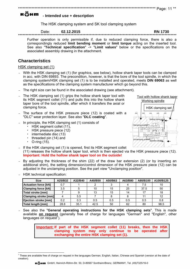
******************************************************************************************** Page: 11 **
- Intended use + description
The HSK clamping system and SK tool clamping system
Date: 02.12.2015 RN 1730 **********************************************************************************************************
GmbH, Heinrich-Röhm-Str. 50, D-89567 Sontheim/Brenz, GERMANY, Tel. (49)7325/16-0
Further operation is only permissible if, due to reduced clamping force, there is also a correspondingly reduced limit bending moment or limit torque acting on the inserted tool. See also "Technical specification" -> "Limit values" below or the specifications on the associated assembly drawing in the attachment.
Characteristics HSK clamping set (1)
– With the HSK clamping set (1) (for graphics, see below), hollow shank taper tools can be clamped in acc. with DIN 69893. The precondition, however, is that the bore of the tool spindle, in which the clamping system/HSK clamping set (1) is to be installed and operated, meets DIN 69063 as well as the specifications of the clamping system manufacturer which go beyond this.
– The right size can be found in the associated drawing (see attachment).
– The HSK clamping set (1) grips the hollow shank taper tool with its HSK segment collet (11) and pulls this into the hollow shank taper bore of the tool spindle, after which it transfers the axial or clamping force.
– The surface of the HSK pressure piece (12) is coated with a "DLC" wear protection layer. See also "DLC coating".
– In principle, the HSK clamping set (1) consists of HSK segment collet (11), HSK pressure piece (12) intermediate disc (13) threaded pin (14) and O-ring (15).
– If the HSK clamping set (1) is opened, first its HSK segment collet (11) releases the hollow shank taper tool, which is then ejected via the HSK pressure piece (12). Important: Hold the hollow shank taper tool on the outside!
– By adjusting the thickness of the shim (22) of the draw bar extension (2) (or by inserting an additional shim), the setting dimension/control dimension of the HSK pressure piece (12) can be adjusted in the unclamping position. See the part view "Unclamping position".
– HSK technical specification:
Size A25/B32 A32/B40 A40/B50 A50/B63 A63/B80 A80/B100 A100/B125
Actuation force [kN] 0.7 1 2 3 4 7.5 10 Clamping force [kN] 3.5 5 10 15 25 37.5 50 Total stroke [mm] 7 9 13 15 14 17 18 Clamping stroke [mm] 4 5.5 7 8 8 11 12 Ejection stroke [mm] 0.2 0.3 0.5 0.5 0.5 0.5 0.8 Total length [mm] 28.8 35.1 42.5 50 62 80 98.5
– See also the "General operating instructions for the HSK clamping sets". This is made available on request (generally free of charge for languages "German" and "English", other languages on request1).
Important: If part of the HSK segment collet (11) breaks, then the HSK clamping system may only continue to be operated after exchanging the entire HSK clamping set (1).
1 These are available free of charge on request in the languages German, English, Italian, Chinese and Spanish (version at the date of creation).
HSK clamping set
HSK clamping set
Tool with hollow shank taper Working spindle
Clamping position
Unclamping position
Setting dimension
Ejection stroke
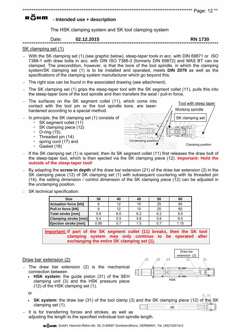
******************************************************************************************** Page: 12 **
- Intended use + description
The HSK clamping system and SK tool clamping system
Date: 02.12.2015 RN 1730 **********************************************************************************************************
GmbH, Heinrich-Röhm-Str. 50, D-89567 Sontheim/Brenz, GERMANY, Tel. (49)7325/16-0
SK clamping set (1)
– With the SK clamping set (1) (see graphic below), steep-taper tools in acc. with DIN 69871 or ISO 7388-1 with draw bolts in acc. with DIN ISO 7388-3 (formerly DIN 69872) and MAS BT can be clamped. The precondition, however, is that the bore of the tool spindle, in which the clamping system/SK clamping set (1) is to be installed and operated, meets DIN 2079 as well as the specifications of the clamping system manufacturer which go beyond this.
– The right size can be found in the associated drawing (see attachment).
– The SK clamping set (1) grips the steep-taper tool with the SK segment collet (11), pulls this into the steep-taper bore of the tool spindle and then transfers the axial / pull-in force.
– The surfaces on the SK segment collet (11), which come into contact with the tool pin or the tool spindle bore, are laser-hardened according to a special method.
– In principle, the SK clamping set (1) consists of SK segment collet (11) SK clamping piece (12) O-ring (15). Threaded pin (14) spring cord (17) and Gasket (18)
– If the SK clamping set (1) is opened, then its SK segment collet (11) first releases the draw bolt of the steep-taper tool, which is then ejected via the SK clamping piece (12). Important: Hold the outside of the steep-taper tool!
– By adapting the screw-in depth of the draw bar extension (21) of the draw bar extension (2) in the SK clamping piece (12) of SK clamping set (1) with subsequent countering with its threaded pin (14), the setting dimension / control dimension of the SK clamping piece (12) can be adjusted in the unclamping position.
– SK technical specification:
Size 30 40 45 50 60
Actuation force [kN] 6 12 15 25 65 Pull-in force [kN] 6 12 15 25 65 Total stroke [mm] 5.8 6.0 6.2 6.2 9.5 Clamping stroke [mm] 5.4 5.5 5.6 5.6 8.5 Ejection stroke [mm] 0.95 0.7 1.5 0.7 1.15
Important: If part of the SK segment collet (11) breaks, then the SK tool clamping system may only continue to be operated after exchanging the entire SK clamping set (1).
Draw bar extension (2)
– The draw bar extension (2) is the mechanical connection between HSK system: the guide piston (31) of the SEH
clamping unit (3) and the HSK pressure piece (12) of the HSK clamping set (1).
or
SK system: the draw bar (31) of the tool clamp (3) and the SK clamping piece (12) of the SK clamping set (1).
– It is for transferring forces and strokes, as well as adjusting the length to the specified individual tool spindle length.
Draw bar extension (2)
HSK
SK
SK clamping set
Tool with steep taper
Working spindle
Clamping position Unclamping position
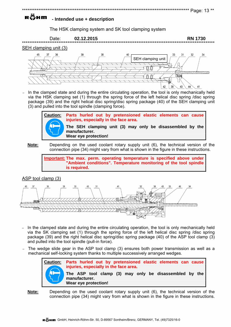
******************************************************************************************** Page: 13 **
- Intended use + description
The HSK clamping system and SK tool clamping system
Date: 02.12.2015 RN 1730 **********************************************************************************************************
GmbH, Heinrich-Röhm-Str. 50, D-89567 Sontheim/Brenz, GERMANY, Tel. (49)7325/16-0
SEH clamping unit (3)
– In the clamped state and during the entire circulating operation, the tool is only mechanically held via the HSK clamping set (1) through the spring force of the left helical disc spring /disc spring package (39) and the right helical disc spring/disc spring package (40) of the SEH clamping unit (3) and pulled into the tool spindle (clamping force).
Caution: Parts hurled out by pretensioned elastic elements can cause injuries, especially in the face area.
The SEH clamping unit (3) may only be disassembled by the manufacturer.
Wear eye protection!
Note: Depending on the used coolant rotary supply unit (6), the technical version of the connection pipe (34) might vary from what is shown in the figure in these instructions.
Important: The max. perm. operating temperature is specified above under "Ambient conditions". Temperature monitoring of the tool spindle is required.
ASP tool clamp (3)
– In the clamped state and during the entire circulating operation, the tool is only mechanically held via the SK clamping set (1) through the spring force of the left helical disc spring /disc spring package (39) and the right helical disc spring/disc spring package (40) of the ASP tool clamp (3) and pulled into the tool spindle (pull-in force).
– The wedge slide gear in the ASP tool clamp (3) ensures both power transmission as well as a mechanical self-locking system thanks to multiple successively arranged wedges.
Caution: Parts hurled out by pretensioned elastic elements can cause injuries, especially in the face area.
The ASP tool clamp (3) may only be disassembled by the manufacturer.
Wear eye protection!
Note: Depending on the used coolant rotary supply unit (6), the technical version of the connection pipe (34) might vary from what is shown in the figure in these instructions.
SEH clamping unit
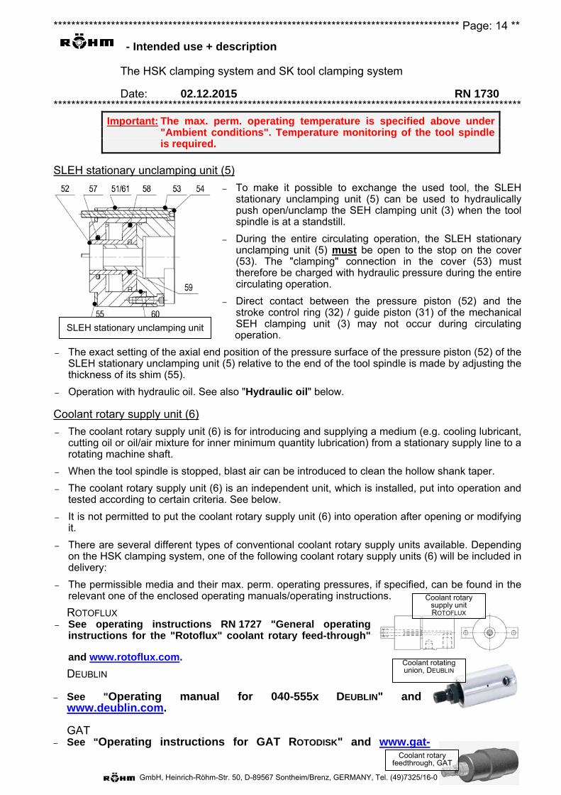
******************************************************************************************** Page: 14 **
- Intended use + description
The HSK clamping system and SK tool clamping system
Date: 02.12.2015 RN 1730 **********************************************************************************************************
GmbH, Heinrich-Röhm-Str. 50, D-89567 Sontheim/Brenz, GERMANY, Tel. (49)7325/16-0
SLEH stationary unclamping unit
Important: The max. perm. operating temperature is specified above under "Ambient conditions". Temperature monitoring of the tool spindle is required.
SLEH stationary unclamping unit (5)
– To make it possible to exchange the used tool, the SLEHstationary unclamping unit (5) can be used to hydraulicallypush open/unclamp the SEH clamping unit (3) when the toolspindle is at a standstill.
– During the entire circulating operation, the SLEH stationaryunclamping unit (5) must be open to the stop on the cover(53). The "clamping" connection in the cover (53) musttherefore be charged with hydraulic pressure during the entirecirculating operation.
– Direct contact between the pressure piston (52) and thestroke control ring (32) / guide piston (31) of the mechanicalSEH clamping unit (3) may not occur during circulatingoperation.
– The exact setting of the axial end position of the pressure surface of the pressure piston (52) of theSLEH stationary unclamping unit (5) relative to the end of the tool spindle is made by adjusting thethickness of its shim (55).
– Operation with hydraulic oil. See also "Hydraulic oil" below.
Coolant rotary supply unit (6)
– The coolant rotary supply unit (6) is for introducing and supplying a medium (e.g. cooling lubricant,cutting oil or oil/air mixture for inner minimum quantity lubrication) from a stationary supply line to arotating machine shaft.
– When the tool spindle is stopped, blast air can be introduced to clean the hollow shank taper.
– The coolant rotary supply unit (6) is an independent unit, which is installed, put into operation andtested according to certain criteria. See below.
– It is not permitted to put the coolant rotary supply unit (6) into operation after opening or modifyingit.
– There are several different types of conventional coolant rotary supply units available. Dependingon the HSK clamping system, one of the following coolant rotary supply units (6) will be included indelivery:
– The permissible media and their max. perm. operating pressures, if specified, can be found in therelevant one of the enclosed operating manuals/operating instructions.
ROTOFLUX – See operating instructions RN 1727 "General operating
instructions for the "Rotoflux" coolant rotary feed-through"
and www.rotoflux.com.
DEUBLIN
– See "Operating manual for 040-555x DEUBLIN" andwww.deublin.com.
GAT– See "Operating instructions for GAT ROTODISK" and www.gat-
Coolant rotary supply unit ROTOFLUX
Coolant rotating union, DEUBLIN
Coolant rotary feedthrough, GAT

******************************************************************************************** Page: 15 **
- Intended use + description
The HSK clamping system and SK tool clamping system
Date: 02.12.2015 RN 1730 **********************************************************************************************************
GmbH, Heinrich-Röhm-Str. 50, D-89567 Sontheim/Brenz, GERMANY, Tel. (49)7325/16-0
mbh.de.
Media feed-through (HSK) – The guide piston (31) of the SEH clamping unit (3) and their connection pipe (34), the draw bar
extension (21) of the draw bar extension (2) as well as the pressure piece HSK (12) of HSK clamping set (1) and its threaded pin (14) are supplied with through holes.
– Through these through holes, despite the stationary unclamping unit (5) being decoupled during circulating operation, a medium supplied via the coolant rotary supply unit (6) can be transferred to the HSK clamping system or to the HSK clamping set (1).
– During the tool change, another medium (e.g. compressed air for taper cleaning) can be switched to as an option, depending on the used rotary supply unit (6).
– Possible media: See "Coolant rotary supply unit (6)".
Media feed-through (SK) – The draw bar (31) of the ASP tool clamp (3) and their connection pipe (34), the draw bar extension
(21) of the draw bar extension (2) as well as the SK clamping piece (12) of the SK clamping set (1) and its threaded pin (14) are supplied with through holes.
– Through these through holes, despite the stationary unclamping unit (5) being decoupled during circulating operation, a medium supplied via the coolant rotary supply unit (6) can be transferred to the HSK clamping system or to the HSK clamping set (1).
– During the tool change, another medium (e.g. compressed air for taper cleaning) can be switched to as an option, depending on the used rotary supply unit (6).
– Possible media: See "Coolant rotary supply unit (6)".
Hydraulic oil – Operation of the SLEH stationary unclamping unit (5) with hydraulic oil.
– The max. perm. operating pressure of the SLEH stationary unclamping unit (5) must be taken from the drawing(s) (see attachment).
– A hydraulic oil with the designation HLP in accordance with DIN 51525 and a kinematic viscosity between 32 and 46 centistokes at 40°C is to be fundamentally used as a hydraulic medium (HLP 32 or HLP 46).
– A pressure filter is to be used against foreign particles in the hydraulic medium. Insertion on an hydraulic unit between the pump and control valve is recommended. The filter gauge should be 0.01 mm (absolute).
Compressed air – The compressed air used for blast air (e.g. for the taper cleaning) must be cleaned and enriched
with a drop of machine lubricating oil (e.g. SHELL MORLINA OIL 10) or a lubricant in acc. with ISO designation C GLP DIN 51502 with viscosity class VG 68 DIN 51519 with a maintenance unit approx. every 6 - 10 min.
– A pressure filter is to be used against foreign particles. Insertion is recommended after the air supply maintenance unit. The filter gauge should be between 0.005 mm and 0.01 mm (absolute).
Cooling lubricant
– A filter is to be used against foreign particles in the cooling lubricant. It is recommended to install it in the intake socket in front of the pump. The filter gauge should be 0.05 mm (absolute).
Attention: If other values are expressly specified for the filter fineness in the text or in drawings, these are binding.
******************************************************************************************** Page: 16 **
- Intended use + description
The HSK clamping system and SK tool clamping system
Date: 02.12.2015 RN 1730 **********************************************************************************************************
GmbH, Heinrich-Röhm-Str. 50, D-89567 Sontheim/Brenz, GERMANY, Tel. (49)7325/16-0
DLC coating:
– With a carbon-containing plasma, DLC layers (= Diamond Like Carbon) can be adhesively deposited on almost all metals and metal alloys (steel, bronze etc.), carbides and light metals (aluminum, magnesium etc.), but also on non-metals (silicon, glass, ceramics, plastic, etc.).
– With this method, it is of considerable advantage that the properties of the DLC layers can be influenced via the various process parameters, such as the treatment duration. With this, the layer thickness, the specific resistance, the hydrogen content, etc. can be adjusted to the requirement profile over a wide range.
– The hardness of the DLC layer is many times higher than the hardness of stainless steel, for example. Therefore, this coating is often found on (highly stressed) tools. Thanks to the DLC coating, the service life of these tools is prolonged, among other things.
Superhard surface (20,000-60,000 N/mm2).
Very thin layer thicknesses from 0.5 – 3 μm or even more can be achieved.
Operation temperature max. 200°C.
Has the same structure as highly crosslinked polymers.
Good anti-adhesive properties.
Excellent corrosion resistance.
Good biocompatibility (approved in the food and medical areas).
Extremely low friction coefficient.
Technical data
See drawing(s) in the attachment.
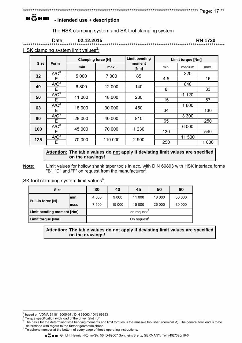
******************************************************************************************** Page: 17 **
- Intended use + description
The HSK clamping system and SK tool clamping system
Date: 02.12.2015 RN 1730 **********************************************************************************************************
GmbH, Heinrich-Röhm-Str. 50, D-89567 Sontheim/Brenz, GERMANY, Tel. (49)7325/16-0
HSK clamping system limit values2:
Size Form Clamping force [N] Limit bending
moment [Nm]
Limit torque [Nm]
min. max. min. medium max.
32 A/C3
5 000 7 000 85 320
E 4.5 16
40 A/C3
6 800 12 000 140 640
E 8 33
50 A/C3
11 000 18 000 230 1 120
E 15 57
63 A/C3
18 000 30 000 450 1 600
E 34 130
80 A/C3
28 000 40 000 810 3 300
E 65 250
100 A/C3
45 000 70 000 1 230 6 000
E 130 540
125 A/C3
70 000 110 000 2 900 11 500
E 250 1 000
Attention: The table values do not apply if deviating limit values are specified on the drawings!
Note: Limit values for hollow shank taper tools in acc. with DIN 69893 with HSK interface forms "B", "D" and "F" on request from the manufacturer5.
SK tool clamping system limit values4:
Size 30 40 45 50 60
Pull-in force [N] min. 4 500 9 000 11 000 18 000 50 000
max. 7 500 15 000 15 000 26 000 80 000
Limit bending moment [Nm] on request5
Limit torque [Nm] On request5
Attention: The table values do not apply if deviating limit values are specified on the drawings!
2 based on VDMA 34181:2005-07 / DIN 69063 / DIN 69853 3 Torque specification with load of the driver (slot nut) 4 The basis for the determined limit bending moments and limit torques is the massive tool shaft (nominal Ø). The general tool load is to be
determined with regard to the further geometric shape. 5 Telephone number at the bottom of every page of these operating instructions.
******************************************************************************************** Page: 18 **
- General warnings
The HSK clamping system and SK tool clamping system
Date: 02.12.2015 RN 1730 **********************************************************************************************************
GmbH, Heinrich-Röhm-Str. 50, D-89567 Sontheim/Brenz, GERMANY, Tel. (49)7325/16-0
Warning: Faulty assembly of the components can endanger the safety of the entire machine.
If one doesn't have one's own skilled personnel, then the clamping device may generally only be disassembled and reassembled by skilled personnel from RÖHM.
I. Qualifications of operating personnel This HSK clamping system / SK tool clamp may only be used, set up and maintained by personnel specially trained or instructed for this purpose and/or who have long years of experience doing this. Personnel lacking any experience in the handling of HSK clamping systems / SK tool clamps are at particular risk of sustaining injury due to incorrect handling and usage, such injuries emanating in particular from the clamping movements and forces involved during setup work.
II. Injury risks Due to technical reasons, this subassembly might be made up of sharp and/or sharp-edged components. Any tasks involving this module should be carried out with extreme care to prevent risks of injury!
1. Activation
In order to prevent unintentionally switching the actuation pressure to the unclamping or clamping line, only locking valves may be used in the hydraulic control.
2. Integrated energy storage
Moving parts which are pretensioned with pressure springs, tractive springs and other springs, or other flexible elements, are a potential source of risk, due to the intrinsic energy stored. Underestimation of this can lead to serious injury caused by uncontrolled, flying parts being propelled through the air. Before performing further work on the associated components, this stored energy must be dissipated. Clamping fixtures which are to be dismantled should be inspected for such sources of danger with the assistance of the respective assembly drawings. The fixture may only be dismantled by authorized RÖHM personnel if it should prove impossible to "safely" dissipate this stored energy.
Caution: Parts hurled out by pretensioned elastic elements can cause injuries, especially in the face area.
The SEH clamping unit (3) / ASP tool clamp (3) may only be
disassembled by the manufacturer. Wear eye protection!
3. Maximum permissible speed
The operating data can be found on the assembly drawing and must not be exceeded.
If the maximum speed of the machine is greater than that permissible for this HSK clamping system / SK tool clamp, then a corresponding speed limiting mechanism must be activated on the machine.
If these values should be exceeded for reasons not caused by us, damage cannot be ruled out, even if this damage isn't immediately apparent. This damage could provoke the danger of flung-away components and possibly personal injury/material damage resulting from this.
4. Exceeding the permissible speed
This equipment is intended for revolving operation. Centrifugal forces created by excessive speed and/or peripheral speed can result in individual parts loosening and becoming potential
******************************************************************************************** Page: 19 **
- General warnings
The HSK clamping system and SK tool clamping system
Date: 02.12.2015 RN 1730 **********************************************************************************************************
GmbH, Heinrich-Röhm-Str. 50, D-89567 Sontheim/Brenz, GERMANY, Tel. (49)7325/16-0
sources of danger for personnel or objects in the near vicinity. Operation at speeds higher than those permitted for these units is prohibited for the above-mentioned reasons.
Even exceeding the permissible values one time can lead to damage and can pose a hazard source not easy to detect. The manufacturer should be informed immediately in such cases so that an inspection of functional and operational safety can be conducted. Further safe operation of the clamping unit can only be guaranteed in this manner.
5. Fixing and replacing screws
Inferior replacements or inadequate fixing of screws which are being changed or become loose can lead to risks of both injury to personnel and material damage. It is therefore imperative that, unless otherwise expressly specified, only such tightening torque as expressly recommended by the screw manufacturer and suitable for the screw quality be applied when tightening fixing screws.
Note: All specified torques must be adhered to with the usual tolerance of the torque wrench of about ± 10%.
The following torque table applies for the common sizes M5 - M24 and qualities 8.8, 10.9 and 12.9:
Quality M5 M6 M8 M10 M12 M14 M16 M18 M20 M22 M24
8.8 5.9 10.1 24.6 48 84 133 206 295 415 567 714 Nm
10.9 8.6 14.9 36.1 71 123 195 302 421 592 807 1017 Nm
12.9 10 17.4 42.2 83 144 229 354 492 692 945 1190 Nm
All details in Nm
Attention: The values in the table do not apply when the tightening torque is expressly specified elsewhere!
Screw quality 12.9 should be selected in cases of doubt when replacing original screws. Fixing screws for clamping inserts, top jaws, fixed stops, preloaded covers, balancing weights and similar elements should fundamentally have quality class 12.9. All fixing screws which, due to the purpose for which they are intended, are loosened frequently and must then be tightened again (e.g. during conversion work) should have their threads and the bearing surface of their heads coated with a lubricating medium every six months (grease paste). Even securely tightened screws can become loose under adverse outside conditions such as, for instance, vibrations. In order to prevent this happening, all safety-related screws (clamping fixture fastening screws, top tooling set fastening screws etc.) must be checked and, if necessary, tightened at regular intervals.
6. SLEH stationary unclamping unit (5) without continuous pressure supply
If the hydraulic or pneumatic connection to the pressure source is interrupted, this could lead to a pressure drop in the active cylinder chamber of the SLEH stationary unclamping unit (5). In the process, the unclamping force of the HSK clamping system / SK tool clamp is usually reduced and the tool can no longer be removed or changed out. For this reason, the release force must be maintained without interruption during the entire removal and supply operation.
Attention: During circulating operation, the hydraulic pressure must act on the clamping connection of the SLEH stationary unclamping unit (5) without interruption.

******************************************************************************************** Page: 20 **
- General warnings
The HSK clamping system and SK tool clamping system
Date: 02.12.2015 RN 1730 **********************************************************************************************************
GmbH, Heinrich-Röhm-Str. 50, D-89567 Sontheim/Brenz, GERMANY, Tel. (49)7325/16-0
7. Maintenance work
The reliability and safety of the HSK clamping system / SK tool clamping system can only be ensured if service regulations in the operating instructions are followed exactly.
It is advantageous to run on several times the end positions of internal moving components after 200 clamping operations at the latest. (Lubricant which has been pressed out is reapplied to the pressure surfaces as a result. The clamping force is maintained for a longer period of time as a consequence).
8. Danger due to ejection
So as to protect the operator against ejected parts and in line with DIN EN 23125 a separating protective equipment must be fitted to the machine tool.
III. Check 1. Stroke monitoring
The stroke monitoring device must be adjusted to suit the new situation if an HSK clamping system with a stroke monitoring device is newly mounted.
2. Maintenance checks
The reliability and safety of the HSK clamping system can only be ensured if service regulations in the operating instructions are followed exactly.
3. Force checks
The clamping force of the HSK clamping system must be checked using a clamping force measuring device at regular intervals.
IV. Environmental hazards 1. Materials
Sometimes, a wide range of lubricating, cooling, cleaning and other media are required for operating an HSK clamping system. These are usually supplied to the HSK clamping system / SK tool clamp via the SLEH stationary unclamping unit (5) or the coolant rotary supply unit (6). Most common are hydraulic oil, coolant and oiled compressed air. Careful attention must be paid to these substances when handling the HSK clamping system / SK tool clamp to prevent them penetrating the soil or contaminating water. Danger! Environmental hazard!
This applies in particular
– during assembly/dismantling, since residual quantities of such substances can still be present in lines, components and piston chambers,
– to porous, defective or incorrectly-fitted seals,
– for coolant and/or blast air, which, for design or production-related reasons, emerge from the HSK clamping system / SK tool clamp during operation or is ejected from this.
These emerging substances must therefore be collected and reused (or disposed of in accordance with applicable regulations)!
2. Noise
In very rare cases, the operation of rotating assemblies can release noise emissions. These are usually determined during commissioning. If these emissions should not be able to be eliminated by means of constructive measures on the HSK clamping system / SK tool clamp or with production-related measures, suitable noise insulation might have to be provided on the machine by the manufacturer or user of the
******************************************************************************************** Page: 21 **
- General warnings
The HSK clamping system and SK tool clamping system
Date: 02.12.2015 RN 1730 **********************************************************************************************************
GmbH, Heinrich-Röhm-Str. 50, D-89567 Sontheim/Brenz, GERMANY, Tel. (49)7325/16-0
machine.
V. Safety-related requirements for the HSK clamping system / SK tool clamping system 1. The actual position of the HSK clamping system / SK tool clamp must be measured (e.g. via
the stroke control ring (32)) and be processed by the machine control, keeping the actuation of the tool spindle drive in mind.
2. The tool spindle may only start up once the unclamping pressure has been dissipated and the clamping pressure built up in the SLEH stationary unclamping unit (5) and clamping has been done in the permissible working range.
3. Unclamping the tool clamping system must only be possible while the tool spindle is at a standstill.
4. If the permissible working range of the clamping is left, a signal must immediately shut down the tool spindle.
5. If the tool spindle is shut down, the tool must remain firmly clamped in until the tool spindle comes to a standstill.
6. If the power should fail and then return again, the possibility of a change in the current switch setting must be ruled out.
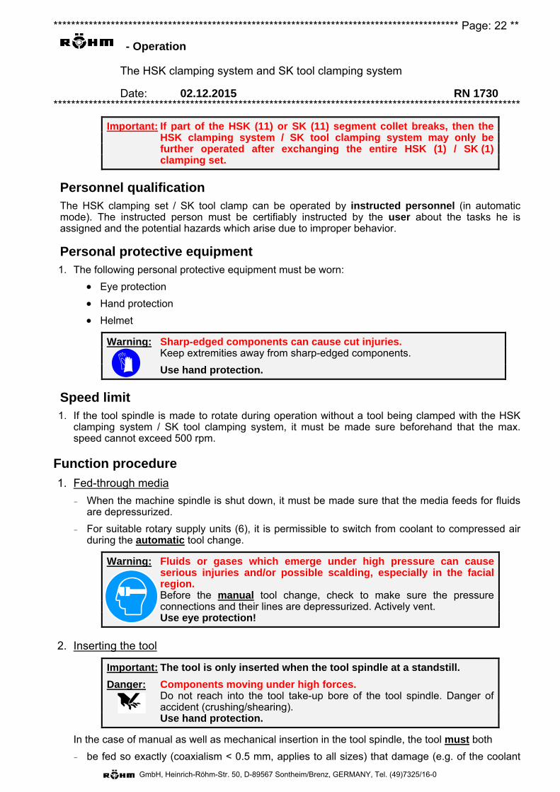
******************************************************************************************** Page: 22 **
- Operation
The HSK clamping system and SK tool clamping system
Date: 02.12.2015 RN 1730 **********************************************************************************************************
GmbH, Heinrich-Röhm-Str. 50, D-89567 Sontheim/Brenz, GERMANY, Tel. (49)7325/16-0
Important: If part of the HSK (11) or SK (11) segment collet breaks, then the HSK clamping system / SK tool clamping system may only be further operated after exchanging the entire HSK (1) / SK (1) clamping set.
Personnel qualification The HSK clamping set / SK tool clamp can be operated by instructed personnel (in automatic mode). The instructed person must be certifiably instructed by the user about the tasks he is assigned and the potential hazards which arise due to improper behavior.
Personal protective equipment 1. The following personal protective equipment must be worn:
Eye protection
Hand protection
Helmet
Warning: Sharp-edged components can cause cut injuries. Keep extremities away from sharp-edged components.
Use hand protection.
Speed limit 1. If the tool spindle is made to rotate during operation without a tool being clamped with the HSK
clamping system / SK tool clamping system, it must be made sure beforehand that the max. speed cannot exceed 500 rpm.
Function procedure
1. Fed-through media
– When the machine spindle is shut down, it must be made sure that the media feeds for fluids are depressurized.
– For suitable rotary supply units (6), it is permissible to switch from coolant to compressed air during the automatic tool change.
Warning: Fluids or gases which emerge under high pressure can cause serious injuries and/or possible scalding, especially in the facial region.
Before the manual tool change, check to make sure the pressure connections and their lines are depressurized. Actively vent.
Use eye protection!
2. Inserting the tool
Important: The tool is only inserted when the tool spindle at a standstill.
Danger: Components moving under high forces. Do not reach into the tool take-up bore of the tool spindle. Danger of
accident (crushing/shearing). Use hand protection.
In the case of manual as well as mechanical insertion in the tool spindle, the tool must both
– be fed so exactly (coaxialism < 0.5 mm, applies to all sizes) that damage (e.g. of the coolant
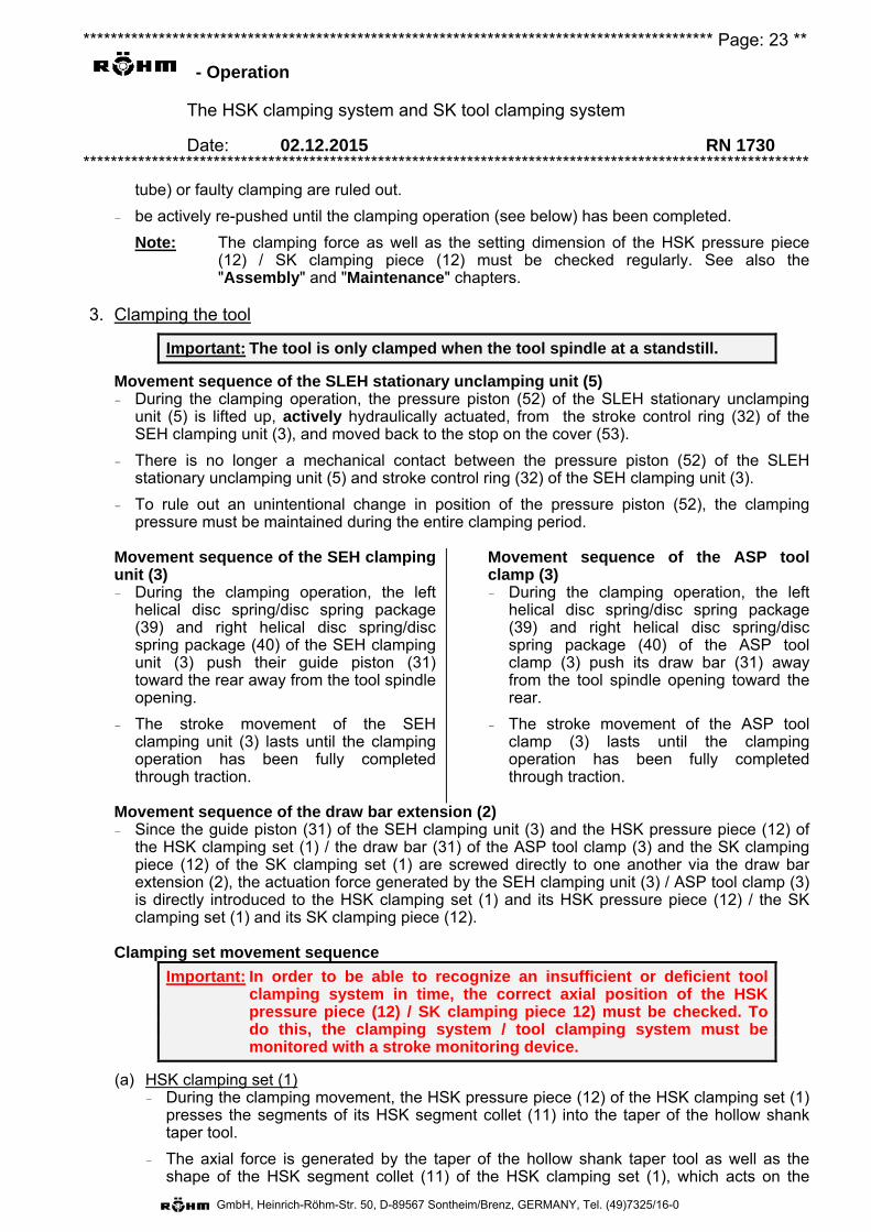
******************************************************************************************** Page: 23 **
- Operation
The HSK clamping system and SK tool clamping system
Date: 02.12.2015 RN 1730 **********************************************************************************************************
GmbH, Heinrich-Röhm-Str. 50, D-89567 Sontheim/Brenz, GERMANY, Tel. (49)7325/16-0
tube) or faulty clamping are ruled out.
– be actively re-pushed until the clamping operation (see below) has been completed.
Note: The clamping force as well as the setting dimension of the HSK pressure piece (12) / SK clamping piece (12) must be checked regularly. See also the "Assembly" and "Maintenance" chapters.
3. Clamping the tool
Important: The tool is only clamped when the tool spindle at a standstill.
Movement sequence of the SLEH stationary unclamping unit (5) – During the clamping operation, the pressure piston (52) of the SLEH stationary unclamping
unit (5) is lifted up, actively hydraulically actuated, from the stroke control ring (32) of the SEH clamping unit (3), and moved back to the stop on the cover (53).
– There is no longer a mechanical contact between the pressure piston (52) of the SLEH stationary unclamping unit (5) and stroke control ring (32) of the SEH clamping unit (3).
– To rule out an unintentional change in position of the pressure piston (52), the clamping pressure must be maintained during the entire clamping period.
Movement sequence of the SEH clamping unit (3) – During the clamping operation, the left
helical disc spring/disc spring package (39) and right helical disc spring/disc spring package (40) of the SEH clamping unit (3) push their guide piston (31) toward the rear away from the tool spindle opening.
– The stroke movement of the SEH clamping unit (3) lasts until the clamping operation has been fully completed through traction.
Movement sequence of the ASP tool clamp (3) – During the clamping operation, the left
helical disc spring/disc spring package (39) and right helical disc spring/disc spring package (40) of the ASP tool clamp (3) push its draw bar (31) away from the tool spindle opening toward the rear.
– The stroke movement of the ASP tool clamp (3) lasts until the clamping operation has been fully completed through traction.
Movement sequence of the draw bar extension (2) – Since the guide piston (31) of the SEH clamping unit (3) and the HSK pressure piece (12) of
the HSK clamping set (1) / the draw bar (31) of the ASP tool clamp (3) and the SK clamping piece (12) of the SK clamping set (1) are screwed directly to one another via the draw bar extension (2), the actuation force generated by the SEH clamping unit (3) / ASP tool clamp (3) is directly introduced to the HSK clamping set (1) and its HSK pressure piece (12) / the SK clamping set (1) and its SK clamping piece (12).
Clamping set movement sequence
Important: In order to be able to recognize an insufficient or deficient tool clamping system in time, the correct axial position of the HSK pressure piece (12) / SK clamping piece 12) must be checked. To do this, the clamping system / tool clamping system must be monitored with a stroke monitoring device.
(a) HSK clamping set (1) – During the clamping movement, the HSK pressure piece (12) of the HSK clamping set (1)
presses the segments of its HSK segment collet (11) into the taper of the hollow shank taper tool.
– The axial force is generated by the taper of the hollow shank taper tool as well as the shape of the HSK segment collet (11) of the HSK clamping set (1), which acts on the
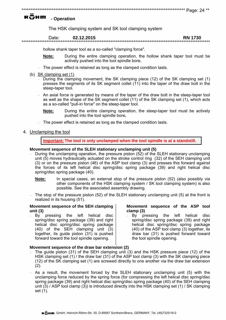
******************************************************************************************** Page: 24 **
- Operation
The HSK clamping system and SK tool clamping system
Date: 02.12.2015 RN 1730 **********************************************************************************************************
GmbH, Heinrich-Röhm-Str. 50, D-89567 Sontheim/Brenz, GERMANY, Tel. (49)7325/16-0
hollow shank taper tool as a so-called "clamping force".
Note: During the entire clamping operation, the hollow shank taper tool must be actively pushed into the tool spindle bore.
– The power effect is retained as long as the clamped condition lasts.
(b) SK clamping set (1) – During the clamping movement, the SK clamping piece (12) of the SK clamping set (1)
presses the segments of its SK segment collet (11) into the taper of the draw bolt in the steep-taper tool.
– An axial force is generated by means of the taper of the draw bolt in the steep-taper tool as well as the shape of the SK segment collet (11) of the SK clamping set (1), which acts as a so-called "pull-in force" on the steep-taper tool.
Note: During the entire clamping operation, the steep-taper tool must be actively pushed into the tool spindle bore.
– The power effect is retained as long as the clamped condition lasts.
4. Unclamping the tool
Important: The tool is only unclamped when the tool spindle is at a standstill.
Movement sequence of the SLEH stationary unclamping unit (5) – During the unclamping operation, the pressure piston (52) of the SLEH stationary unclamping
unit (5) moves hydraulically actuated on the stroke control ring (32) of the SEH clamping unit (3) or on the pressure piston (46) of the ASP tool clamp (3) and presses this forward against the forces of its left helical disc spring/disc spring package (39) and right helical disc spring/disc spring package (40).
Note: In special cases, an external stop of the pressure piston (52) (also possibly via other components of the HSK clamping system / SK tool clamping system) is also possible. See the associated assembly drawing.
– The stop of the pressure piston (52) of the SLEH stationary unclamping unit (5) at the front is realized in its housing (51).
Movement sequence of the SEH clamping unit (3) – By pressing the left helical disc
spring/disc spring package (39) and right helical disc spring/disc spring package (40) of the SEH clamping unit (3) together, its guide piston (31) is pushed forward toward the tool spindle opening.
Movement sequence of the ASP tool clamp (3) – By pressing the left helical disc
spring/disc spring package (39) and right helical disc spring/disc spring package (40) of the ASP tool clamp (3) together, its draw bar (31) is pushed forward toward the tool spindle opening.
Movement sequence of the draw bar extension (2) – The guide piston (31) of the SEH clamping unit (3) and the HSK pressure piece (12) of the
HSK clamping set (1) / the draw bar (31) of the ASP tool clamp (3) with the SK clamping piece (12) of the SK clamping set (1) are screwed directly to one another via the draw bar extension (2).
– As a result, the movement forced by the SLEH stationary unclamping unit (5) with the unclamping force reduced by the spring force (for compressing the left helical disc spring/disc spring package (39) and right helical disc spring/disc spring package (40) of the SEH clamping unit (3) / ASP tool clamp (3)) is introduced directly into the HSK clamping set (1) / SK clamping set (1).
******************************************************************************************** Page: 25 **
- Operation
The HSK clamping system and SK tool clamping system
Date: 02.12.2015 RN 1730 **********************************************************************************************************
GmbH, Heinrich-Röhm-Str. 50, D-89567 Sontheim/Brenz, GERMANY, Tel. (49)7325/16-0
Movement sequence of the HSK clamping set (1) – The HSK pressure piece (12) of the HSK
clamping set (1), due to the contact geometries to its HSK segment collet (11), causes the segments of the HSK segment collet (11) of the HSK clamping set (1) to fold inward.
– This exposes the taper of the hollow shank taper tool.
– As a result of the pressure piece (12) setting, the hollow shank taper tool is actively ejected from the tool spindle by a small amount. Important: Hold the hollow shank taper tool on the outside!
Movement sequence of the SK clamping set (1) – The SK clamping piece (12) of the SK
clamping set (1), due to the contact geometries to its SK segment collet (11) and the inserted spring cord (17), causes the segments of the SK segment collet (11) of the SK clamping set (1) to fold outward.
– With this, the draw bolt in the steep-taper tool is released.
– Due to the setting of the SK clamping piece (12), the steep-taper tool is actively ejected from the tool spindle by a small amount. Important: Hold the outside of the steep-taper tool!
Danger: Components moving under high forces. Do not reach into the tool take-up bore of the tool spindle. Danger of
accident (crushing/shearing). Wear hand protection
5. Removing the tool
Important: The tool is only removed when the tool spindle is at a standstill.
– The tool can be removed from the tool spindle and exchanged for a different one. This completes the function circuit.

******************************************************************************************* Page: 26 ***
- Assembly
The HSK clamping system and SK tool clamping system
Date: 02.12.2015 RN 1730 **********************************************************************************************************
GmbH, Heinrich-Röhm-Str. 50, D-89567 Sontheim/Brenz, GERMANY, Tel. (49)7325/16-0
I. Personnel qualificationThe HSK clamping system / SK tool clamp may only be installed on/in the tool spindle bytrained, skilled personnel from the manufacturer of the tool spindle, the machine orclamping system, who, based on their professional training, are familiar with the work assignedto them as well as the potential hazards, and are able to minimize these by taking suitable safetymeasures.
II. Personal protective equipment1. The following personal protective equipment must be worn:
Eye protection
Helmet
Hand protection
Foot protection
Warning: Sharp-edged components can cause cut injuries. Keep extremities away from sharp-edged components.
Use hand protection.
Danger: Parts/tools pulled out of the clamping due to insufficient mechanical strength or overload (bending, torque) can cause serious injuries.
Wear personal protective gear.
III. Space requirement1. The available work area on the end of the tool spindle for mounting the HSK clamping system
or SK tool clamping system should be at least 1x the tool spindle length.
IV. Tightening torques for cylinder screws1. If cylinder screws (according to DIN 912 + DIN 6912) have to be loosened or tightened for
mounting or dismounting / for the operation of the clamping system, then the tighteningtorques according to the VDI directive 2230 are generally to be applied.
2. This is the only way to guarantee the greatest possible strength of the cylinder screw.
3. A selection of these tightening torques for the usual screw sizes and for 3 different screwqualities (8.8 to 12.9) can be found in the tightening torque table in the chapter "Generalwarnings" in the paragraph "Fastening and exchange of screws".
4. For this clamping system, screw quality 12.9 is used almost exclusively. If in doubt, refer to thepiece list: There, the screw qualities for standard screws are specified. The screw quality canalso be found on the screw head.
5. Tightening torques deviating from this specification for screws which have to be loosened ortightened in the scope of mounting or dismounting or during the operation of the clampingsystem are given on the assembly drawing.
V. Speed limit1. If the tool spindle has to be made to rotate during installation or commissioning of the HSK
clamping system / SK tool clamping system, then it must be made sure beforehand that themax. speed cannot exceed 500 rpm.
VI. Pressures1. All actuation pressures must be shut down during all installation steps as well as during setting
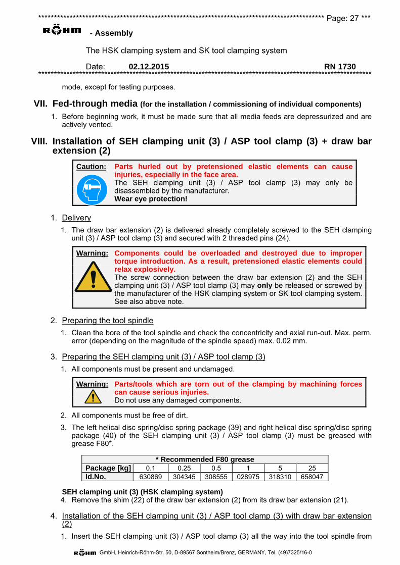
******************************************************************************************* Page: 27 ***
- Assembly
The HSK clamping system and SK tool clamping system
Date: 02.12.2015 RN 1730 **********************************************************************************************************
GmbH, Heinrich-Röhm-Str. 50, D-89567 Sontheim/Brenz, GERMANY, Tel. (49)7325/16-0
mode, except for testing purposes.
VII. Fed-through media (for the installation / commissioning of individual components)
1. Before beginning work, it must be made sure that all media feeds are depressurized and are actively vented.
VIII. Installation of SEH clamping unit (3) / ASP tool clamp (3) + draw bar extension (2)
Caution: Parts hurled out by pretensioned elastic elements can cause injuries, especially in the face area.
The SEH clamping unit (3) / ASP tool clamp (3) may only be disassembled by the manufacturer.
Wear eye protection!
1. Delivery
1. The draw bar extension (2) is delivered already completely screwed to the SEH clamping unit (3) / ASP tool clamp (3) and secured with 2 threaded pins (24).
Warning: Components could be overloaded and destroyed due to improper torque introduction. As a result, pretensioned elastic elements could relax explosively.
The screw connection between the draw bar extension (2) and the SEH clamping unit (3) / ASP tool clamp (3) may only be released or screwed by the manufacturer of the HSK clamping system or SK tool clamping system. See also above note.
2. Preparing the tool spindle
1. Clean the bore of the tool spindle and check the concentricity and axial run-out. Max. perm. error (depending on the magnitude of the spindle speed) max. 0.02 mm.
3. Preparing the SEH clamping unit (3) / ASP tool clamp (3)
1. All components must be present and undamaged.
Warning: Parts/tools which are torn out of the clamping by machining forces can cause serious injuries.
Do not use any damaged components.
2. All components must be free of dirt.
3. The left helical disc spring/disc spring package (39) and right helical disc spring/disc spring package (40) of the SEH clamping unit (3) / ASP tool clamp (3) must be greased with grease F80*.
SEH clamping unit (3) (HSK clamping system) 4. Remove the shim (22) of the draw bar extension (2) from its draw bar extension (21).
4. Installation of the SEH clamping unit (3) / ASP tool clamp (3) with draw bar extension (2)
1. Insert the SEH clamping unit (3) / ASP tool clamp (3) all the way into the tool spindle from
* Recommended F80 grease Package [kg] 0.1 0.25 0.5 1 5 25 Id.No. 630869 304345 308555 028975 318310 658047
******************************************************************************************* Page: 28 ***
- Assembly
The HSK clamping system and SK tool clamping system
Date: 02.12.2015 RN 1730 **********************************************************************************************************
GmbH, Heinrich-Röhm-Str. 50, D-89567 Sontheim/Brenz, GERMANY, Tel. (49)7325/16-0
the rear with the draw bar extension (2) screwed in.
SEH clamping unit (3) (HSK clamping system) 2. Push the shim (22) of the draw bar extension (2) into the tool spindle bore from the front
and onto the draw bar extension (21) of the draw bar extension (2).
Note: The shim (22) of the draw bar extension (2) has several threaded bores. Usingthese threads and matching long screws, the mounting/dismounting of the shim(22) of the draw bar extension (2) can be simplified.
HSK clamping system / SK tool clamp 3. Check the whole assembly with the specified dimensions. See the assembly drawing in the
attachment.
IX. Assembly of the SLEH stationary unclamping unit (5)1. Delivery
1. The SLEH stationary unclamping unit (5) is delivered completely preassembled.
2. Preparing the tool spindle
1. There must be an adapter flange matching the tool spindle housing available with take-up/mounting options for several stroke control switches, and this must be mounted to thetool spindle housing.
2. The prescribed dimension between the end of the tool spindle and the screw-on surface ofthe housing (51) of the SLEH stationary unclamping unit (5) on the adapter flange must becomplied with. See drawings in the attachment. The thickness of the shim (55) might haveto be adjusted within the likewise prescribed tolerances.
3. Assembly of the SLEH stationary unclamping unit (5)
1. Screw the complete SLEH stationary unclamping unit (5) to the adapter flange fastenedstationary to the tool spindle housing with the cylinder screws (54) to the prescribedtightening torque (see note).
Note: The prescribed tightening torque for the cylinder screws (54) is specified next tothese on the take-up cover (53).If this should not be the case, use the prescribed tightening torque from thetightening torque table in the chapter "General warnings" in the paragraph"Fastening and exchanging screws". See also item IV.
4. Hydraulic connections, SLEH stationary unclamping unit (5)
1. The hydraulic connections of the SLEH stationary unclampingunit (5) are located on its cover (53). The connection thread sizesas well as the connection designations (here, e.g. "S" and "L")can be found on the enclosed drawings. See also the rightschematic diagram.
2. The connection lines may be designed as hose lines or pipeconnections as long as they are designed such that the effect ofexternal forces on the cover (53) can be ruled out.
3. Only connection lines can be used whose pressures as well as environmental influences forthe application are suitable with regard to the type of media.
4. To remove any contamination from the connection lines, these should be flushed with thelater-intended flow medium or blown through before connecting to the cover (53).
5. Remove the closure caps from the hydraulic connections in the cover (53).
S L
******************************************************************************************* Page: 29 ***
- Assembly
The HSK clamping system and SK tool clamping system
Date: 02.12.2015 RN 1730 **********************************************************************************************************
GmbH, Heinrich-Röhm-Str. 50, D-89567 Sontheim/Brenz, GERMANY, Tel. (49)7325/16-0
Note: It is recommended that the closure caps be kept in a safe place, as these can be useful if SLEH stationary unclamping unit (5) is dismounted at a later stage.
Contamination penetrating into the SLEH stationary unclamping unit (5) must be avoided under all circumstances, since otherwise, premature wear has to be expected on the dynamically stressed seals and sliding surfaces.
6. Establish the hydraulic connections to the cover (53). The tightening torques for the screw joints given on the enclosed drawings must be complied with.
Note: When filling the SLEH stationary unclamping unit (5) with hydraulic oil for the first time, reduce the hydraulic pressure to max. 10 bar.
X. Assembly of the coolant rotary supply unit (6) – There are several different types of conventional coolant rotary supply units available. Depending
on the HSK clamping system, one of the following coolant rotary supply units (6) will be included in delivery:
– Refer to the corresponding enclosed instructions for assembly:
ROTOFLUX Operating instructions RN 1727 "General operating instructions
for coolant rotary supply unit" ROTOFLUX".
"ROTOFLUX installation and run-in instructions" (English/Italian).
DEUBLIN
"Operating manual 040-555x DEUBLIN".
"DEUBLIN installation 040-505".
GAT "GAT Rotodisk operating instructions".
– After installing the connections, check again whether the feed lines are correct and check for leaks.
Note: You can find updated information about its coolant rotary supply unit on the websites of the manufacturer. The web addresses are listed in the chapter "Intended use + Description" in the section "Coolant rotary supply unit (6)".
When the coolant rotary supply unit (6) is charged with the intended medium for the first time, first reduce its pressure to max. 10 bar (liquids) or 3 bar (gases).
ROTOFLUX coolant rotary supply unit
Coolant rotary supply unit, DEUBLIN
Coolant rotary supply unit, GAT
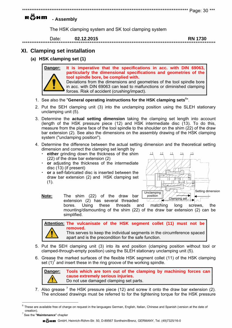
******************************************************************************************* Page: 30 ***
- Assembly
The HSK clamping system and SK tool clamping system
Date: 02.12.2015 RN 1730 **********************************************************************************************************
GmbH, Heinrich-Röhm-Str. 50, D-89567 Sontheim/Brenz, GERMANY, Tel. (49)7325/16-0
XI. Clamping set installation
(a) HSK clamping set (1)
Danger: It is imperative that the specifications in acc. with DIN 69063, particularly the dimensional specifications and geometries of the tool spindle bore, be complied with.
Deviations from the dimensions and geometries of the tool spindle bore in acc. with DIN 69063 can lead to malfunctions or diminished clamping forces. Risk of accident (crushing/impact).
1. See also the "General operating instructions for the HSK clamping sets6".
2. Put the SEH clamping unit (3) into the unclamping position using the SLEH stationary unclamping unit (5).
3. Determine the actual setting dimension taking the clamping set length into account (length of the HSK pressure piece (12) and HSK intermediate disc (13). To do this, measure from the plane face of the tool spindle to the shoulder on the shim (22) of the draw bar extension (2). See also the dimensions on the assembly drawing of the HSK clamping system ("unclamping position").
4. Determine the difference between the actual setting dimension and the theoretical setting dimension and correct the clamping set length by either grinding down the thickness of the shim
(22) of the draw bar extension (2) or adjusting the thickness of the intermediate
disc (13) (if present) or a self-fabricated disc is inserted between the
draw bar extension (2) and HSK clamping set (1).
Note: The shim (22) of the draw bar extension (2) has several threaded bores. Using these threads and matching long screws, the mounting/dismounting of the shim (22) of the draw bar extension (2) can be simplified.
Attention: The vulcanisate of the HSK segment collet (11) must not be removed.
This serves to keep the individual segments in the circumference spaced apart and is the precondition for the safe function.
5. Put the SEH clamping unit (3) into its end position (clamping position without tool or clamped-through-empty position) using the SLEH stationary unclamping unit (5).
6. Grease the marked surfaces of the flexible HSK segment collet (11) of the HSK clamping set (1)7 and insert these in the ring groove of the working spindle.
Danger: Tools which are torn out of the clamping by machining forces can cause extremely serious injuries.
Do not use damaged clamping set parts.
7. Also grease 7 the HSK pressure piece (12) and screw it onto the draw bar extension (2). The enclosed drawings must be referred to for the tightening torque for the HSK pressure
6 These are available free of charge on request in the languages German, English, Italian, Chinese and Spanish (version at the date of
creation). 7
See the "Maintenance" chapter
Unclamping position
Clamping set
Setting dimension
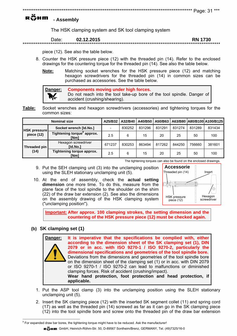
******************************************************************************************* Page: 31 ***
- Assembly
The HSK clamping system and SK tool clamping system
Date: 02.12.2015 RN 1730 **********************************************************************************************************
GmbH, Heinrich-Röhm-Str. 50, D-89567 Sontheim/Brenz, GERMANY, Tel. (49)7325/16-0
Hexagon screwdriver
AccessorieInsert Threaded pin (14)
HSK pressure piece (12)
piece (12). See also the table below.
8. Counter the HSK pressure piece (12) with the threaded pin (14). Refer to the enclosed drawings for the countering torque for the threaded pin (14). See also the table below.
Note: Matching socket wrenches for the HSK pressure piece (12) and matching hexagon screwdrivers for the threaded pin (14) in common sizes can be purchased as accessories. See the table below.
Danger: Components moving under high forces. Do not reach into the tool take-up bore of the tool spindle. Danger of
accident (crushing/shearing).
Table: Socket wrenches and hexagon screwdrivers (accessories) and tightening torques for the common sizes:
Nominal size A25/B32 A32/B40 A40/B50 A50/B63 A63/B80 A80/B100 A100/B125
HSK pressure piece (12)
Socket wrench [Id.No.] - 830252 831296 831291 831274 831289 831434
Tightening torque8 approx. [Nm]
2.5 6 15 20 25 50 100
Threaded pin (14)
Hexagon screwdriver [Id.No.]
671237 830253 863494 817262 844250 756660 381601
Tightening torque approx. [Nm]
2.5 6 15 20 25 50 100
The tightening torques can also be found on the enclosed drawings.
9. Put the SEH clamping unit (3) into the unclamping position using the SLEH stationary unclamping unit (5).
10. At the end of assembly, check the actual setting dimension one more time. To do this, measure from the plane face of the tool spindle to the shoulder on the shim (22) of the draw bar extension (2). See also the dimensions on the assembly drawing of the HSK clamping system ("unclamping position").
Important: After approx. 100 clamping strokes, the setting dimension and the countering of the HSK pressure piece (12) must be checked again.
(b) SK clamping set (1)
Danger: It is imperative that the specifications be complied with, either according to the dimension sheet of the SK clamping set (1), DIN 2079 or in acc. with ISO 9270-1 / ISO 9270-2, particularly the dimensional specifications and geometries of the tool spindle bore.
Deviations from the dimensions and geometries of the tool spindle bore on the dimension sheet of the clamping set (1) or in acc. with DIN 2079 or ISO 9270-1 / ISO 9270-2 can lead to malfunctions or diminished clamping forces. Risk of accident (crushing/impact).
Wear hand protection, foot protection and head protection, if applicable.
1. Put the ASP tool clamp (3) into the unclamping position using the SLEH stationary unclamping unit (5).
2. Insert the SK clamping piece (12) with the inserted SK segment collet (11) and spring cord (17) as well as the threaded pin (14) screwed as far as it can go in the SK clamping piece (12) into the tool spindle bore and screw onto the threaded pin of the draw bar extension
8 For expanded draw bar bores, the tightening torque might have to be reduced. Ask the manufacturer!
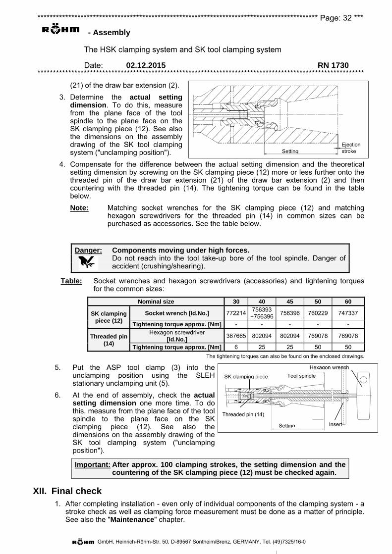
******************************************************************************************* Page: 32 ***
- Assembly
The HSK clamping system and SK tool clamping system
Date: 02.12.2015 RN 1730 **********************************************************************************************************
GmbH, Heinrich-Röhm-Str. 50, D-89567 Sontheim/Brenz, GERMANY, Tel. (49)7325/16-0
Setting Ejection stroke
Setting
SK clamping piece
Threaded pin (14)
Insert
Hexagon wrench
Tool spindle
(21) of the draw bar extension (2).
3. Determine the actual setting dimension. To do this, measure from the plane face of the tool spindle to the plane face on the SK clamping piece (12). See also the dimensions on the assembly drawing of the SK tool clamping system ("unclamping position").
4. Compensate for the difference between the actual setting dimension and the theoretical setting dimension by screwing on the SK clamping piece (12) more or less further onto the threaded pin of the draw bar extension (21) of the draw bar extension (2) and then countering with the threaded pin (14). The tightening torque can be found in the table below.
Note: Matching socket wrenches for the SK clamping piece (12) and matching hexagon screwdrivers for the threaded pin (14) in common sizes can be purchased as accessories. See the table below.
Danger: Components moving under high forces. Do not reach into the tool take-up bore of the tool spindle. Danger of
accident (crushing/shearing).
Table: Socket wrenches and hexagon screwdrivers (accessories) and tightening torques for the common sizes:
Nominal size 30 40 45 50 60
SK clamping piece (12)
Socket wrench [Id.No.] 772214 756393
+756396 756396 760229 747337
Tightening torque approx. [Nm] - - - - -
Threaded pin (14)
Hexagon screwdriver [Id.No.]
367665 802094 802094 769078 769078
Tightening torque approx. [Nm] 6 25 25 50 50 The tightening torques can also be found on the enclosed drawings.
5. Put the ASP tool clamp (3) into the unclamping position using the SLEH stationary unclamping unit (5).
6. At the end of assembly, check the actual setting dimension one more time. To do this, measure from the plane face of the tool spindle to the plane face on the SK clamping piece (12). See also the dimensions on the assembly drawing of the SK tool clamping system ("unclamping position").
Important: After approx. 100 clamping strokes, the setting dimension and the countering of the SK clamping piece (12) must be checked again.
XII. Final check 1. After completing installation - even only of individual components of the clamping system - a
stroke check as well as clamping force measurement must be done as a matter of principle. See also the "Maintenance" chapter.
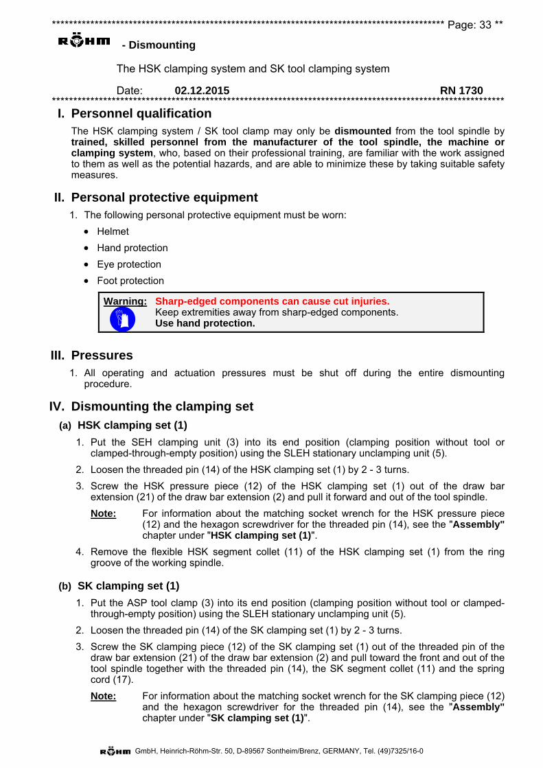
******************************************************************************************** Page: 33 **
- Dismounting
The HSK clamping system and SK tool clamping system
Date: 02.12.2015 RN 1730 **********************************************************************************************************
GmbH, Heinrich-Röhm-Str. 50, D-89567 Sontheim/Brenz, GERMANY, Tel. (49)7325/16-0
I. Personnel qualification The HSK clamping system / SK tool clamp may only be dismounted from the tool spindle by trained, skilled personnel from the manufacturer of the tool spindle, the machine or clamping system, who, based on their professional training, are familiar with the work assigned to them as well as the potential hazards, and are able to minimize these by taking suitable safety measures.
II. Personal protective equipment 1. The following personal protective equipment must be worn:
Helmet
Hand protection
Eye protection
Foot protection
Warning: Sharp-edged components can cause cut injuries. Keep extremities away from sharp-edged components. Use hand protection.
III. Pressures 1. All operating and actuation pressures must be shut off during the entire dismounting
procedure.
IV. Dismounting the clamping set
(a) HSK clamping set (1)
1. Put the SEH clamping unit (3) into its end position (clamping position without tool or clamped-through-empty position) using the SLEH stationary unclamping unit (5).
2. Loosen the threaded pin (14) of the HSK clamping set (1) by 2 - 3 turns.
3. Screw the HSK pressure piece (12) of the HSK clamping set (1) out of the draw bar extension (21) of the draw bar extension (2) and pull it forward and out of the tool spindle.
Note: For information about the matching socket wrench for the HSK pressure piece (12) and the hexagon screwdriver for the threaded pin (14), see the "Assembly" chapter under "HSK clamping set (1)".
4. Remove the flexible HSK segment collet (11) of the HSK clamping set (1) from the ring groove of the working spindle.
(b) SK clamping set (1)
1. Put the ASP tool clamp (3) into its end position (clamping position without tool or clamped-through-empty position) using the SLEH stationary unclamping unit (5).
2. Loosen the threaded pin (14) of the SK clamping set (1) by 2 - 3 turns.
3. Screw the SK clamping piece (12) of the SK clamping set (1) out of the threaded pin of the draw bar extension (21) of the draw bar extension (2) and pull toward the front and out of the tool spindle together with the threaded pin (14), the SK segment collet (11) and the spring cord (17).
Note: For information about the matching socket wrench for the SK clamping piece (12) and the hexagon screwdriver for the threaded pin (14), see the "Assembly" chapter under "SK clamping set (1)".
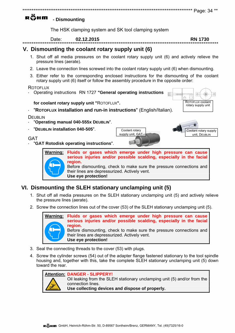
******************************************************************************************** Page: 34 **
- Dismounting
The HSK clamping system and SK tool clamping system
Date: 02.12.2015 RN 1730 **********************************************************************************************************
GmbH, Heinrich-Röhm-Str. 50, D-89567 Sontheim/Brenz, GERMANY, Tel. (49)7325/16-0
V. Dismounting the coolant rotary supply unit (6) 1. Shut off all media pressures on the coolant rotary supply unit (6) and actively relieve the
pressure lines (aerate).
2. Leave the connection lines screwed into the coolant rotary supply unit (6) when dismounting.
3. Either refer to the corresponding enclosed instructions for the dismounting of the coolant rotary supply unit (6) itself or follow the assembly procedure in the opposite order:
ROTOFLUX Operating instructions RN 1727 "General operating instructions
for coolant rotary supply unit "ROTOFLUX".
"ROTOFLUX installation and run-in instructions" (English/Italian).
DEUBLIN "Operating manual 040-555x DEUBLIN".
"DEUBLIN installation 040-505".
GAT "GAT Rotodisk operating instructions".
Warning: Fluids or gases which emerge under high pressure can cause serious injuries and/or possible scalding, especially in the facial region.
Before dismounting, check to make sure the pressure connections and their lines are depressurized. Actively vent.
Use eye protection!
VI. Dismounting the SLEH stationary unclamping unit (5) 1. Shut off all media pressures on the SLEH stationary unclamping unit (5) and actively relieve
the pressure lines (aerate).
2. Screw the connection lines out of the cover (53) of the SLEH stationary unclamping unit (5).
Warning: Fluids or gases which emerge under high pressure can cause serious injuries and/or possible scalding, especially in the facial region.
Before dismounting, check to make sure the pressure connections and their lines are depressurized. Actively vent.
Use eye protection!
3. Seal the connecting threads to the cover (53) with plugs.
4. Screw the cylinder screws (54) out of the adapter flange fastened stationary to the tool spindle housing and, together with this, take the complete SLEH stationary unclamping unit (5) down toward the rear.
Attention: DANGER - SLIPPERY! Oil leaking from the SLEH stationary unclamping unit (5) and/or from the
connection lines. Use collecting devices and dispose of properly.
Coolant rotary supply unit, DEUBLIN
Coolant rotary supply unit, GAT
ROTOFLUX coolant rotary supply unit
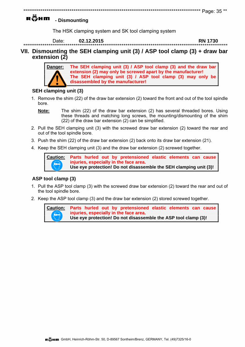
******************************************************************************************** Page: 35 **
- Dismounting
The HSK clamping system and SK tool clamping system
Date: 02.12.2015 RN 1730 **********************************************************************************************************
GmbH, Heinrich-Röhm-Str. 50, D-89567 Sontheim/Brenz, GERMANY, Tel. (49)7325/16-0
VII. Dismounting the SEH clamping unit (3) / ASP tool clamp (3) + draw barextension (2)
Danger: The SEH clamping unit (3) / ASP tool clamp (3) and the draw bar extension (2) may only be screwed apart by the manufacturer! The SEH clamping unit (3) / ASP tool clamp (3) may only be disassembled by the manufacturer!
SEH clamping unit (3)
1. Remove the shim (22) of the draw bar extension (2) toward the front and out of the tool spindlebore.
Note: The shim (22) of the draw bar extension (2) has several threaded bores. Usingthese threads and matching long screws, the mounting/dismounting of the shim(22) of the draw bar extension (2) can be simplified.
2. Pull the SEH clamping unit (3) with the screwed draw bar extension (2) toward the rear andout of the tool spindle bore.
3. Push the shim (22) of the draw bar extension (2) back onto its draw bar extension (21).
4. Keep the SEH clamping unit (3) and the draw bar extension (2) screwed together.
Caution: Parts hurled out by pretensioned elastic elements can cause injuries, especially in the face area. Use eye protection! Do not disassemble the SEH clamping unit (3)!
ASP tool clamp (3)
1. Pull the ASP tool clamp (3) with the screwed draw bar extension (2) toward the rear and out ofthe tool spindle bore.
2. Keep the ASP tool clamp (3) and the draw bar extension (2) stored screwed together.
Caution: Parts hurled out by pretensioned elastic elements can cause injuries, especially in the face area. Use eye protection! Do not disassemble the ASP tool clamp (3)!
******************************************************************************************** Page: 36 **
- Maintenance
The HSK clamping system and SK tool clamping system
Date: 02.12.2015 RN 1730 **********************************************************************************************************
GmbH, Heinrich-Röhm-Str. 50, D-89567 Sontheim/Brenz, GERMANY, Tel. (49)7325/16-0
Personnel qualifications To carry out the work that has to be done during the course of maintenance measures, different personnel qualifications are required. These are categorized into the following groups:
1. Qualification group 1 Instructed personnel: The instructed person must be certifiably instructed by the user about the tasks he is assigned and the potential hazards which arise due to improper behavior.
Assigned tasks: – Inspection (e.g. visual inspection, clamping force check, checking the signals output
(adjustment) of the stroke control sensors, leak checks). – Cleaning and lubrication of the tool spindle cone or tool shaft. – Setting dimension check.
2. Qualification group 2 Trained, skilled personnel from the manufacturer of the tool spindle, machine or the clamping system or from the user: Skilled personnel who, based on their professional training, are familiar with the work assigned to them as well as the potential hazards, and are able to minimize these by taking suitable safety measures.
Assigned tasks: – All maintenance and repair measures on the HSK clamping system / SK tool clamp, which are
limited to the removal and installation of entire groups. The draw bar extension (2) screwed to the SEH clamping unit (3) / ASP tool clamp (3) counts as 1 group here.
– Setting dimension correction.
3. Qualification group 3 Trained, skilled personnel from the clamping system manufacturer: Skilled personnel who, based on their professional training, are familiar with the work assigned to them as well as the potential hazards, and are able to minimize these by taking suitable safety measures.
Assigned tasks: – Dismounting the draw bar extension (2) and SEH clamping unit (3) / ASP tool clamp (3). – Disassembly of the SEH clamping unit (3) / ASP tool clamp (3).
Personal protective equipment 1. The following personal protective equipment must be worn:
Hand protection
Helmet
Eye protection
Pressures 1. Except for testing purposes, all actuation pressures must be switched off during maintenance
measures. This particularly applies when the tool take-up has to be grabbed for maintenance purposes.
Warning: Fluids or gases which emerge under high pressure can cause serious injuries and/or possible scalding, especially in the facial region.
Before maintenance measures, check to make sure the pressure connections and their lines are depressurized. Actively vent.
Wear eye protection!
******************************************************************************************** Page: 37 **
- Maintenance
The HSK clamping system and SK tool clamping system
Date: 02.12.2015 RN 1730 **********************************************************************************************************
GmbH, Heinrich-Röhm-Str. 50, D-89567 Sontheim/Brenz, GERMANY, Tel. (49)7325/16-0
Function and safety check:
Warning: Sharp-edged components can cause cut injuries. Keep extremities away from sharp-edged components. Use hand protection.
Danger: Components moving under high forces. Do not reach into the tool take-up bore of the tool spindle. Danger of accident (crushing/shearing). Use hand protection.
Weekly or after 75 hours of operation9
1. Visually inspect the HSK clamping set (1) / SK clamping set (1) (qualification group 1): Clamping movement Check the adjustment (signal output) of the stroke control sensors above the stroke control ring
(32) of the SEH clamping unit (3) or ASP tool clamp (3). Damage Leak check of SLEH stationary unclamping unit (5) and coolant rotary supply unit (6). Contamination, with cleaning and lubrication of tool spindle cone or tool shaft (also O-ring (15) of
the HSK clamping set (1)), if necessary. Degreasing
In the event of Stroke control error: Optimize the adjustment of the stroke control sensors according to their
operating instructions. Damage: Exchange the entire HSK clamping set (1) / SK clamping set (1)
(qualification group 2). Oil/coolant escape: Dismount the SLEH stationary unclamping unit (5) and fix the cause of the
leak. Insert new seals, if necessary. Then remount the SLEH stationary unclamping unit (5). If there is a coolant rotary supply unit (6), replace this.
contamination: Remove the HSK clamping set (1) / SK clamping set (1) and clean, together with the inner contour of the spindle (qualification group 2). Observe the warning!
degreasing: Find the reason for the degreasing and rectify it (e.g. defective seals, unsuitable cooling lubricant, washing out in unfitted state). Relubricate the HSK segment collet (11) / SK segment collet (11) (in installed state, e.g. using a brush). For lubricants, see below (qualification group 2).
Note: The use of external compressed air for the general cleaning of the HSK clamping system / SK tool clamping system is not permissible.
Monthly, or after 300 hours of operation9
1. Check the setting dimension of the HSK pressure piece (12) / SK clamping piece (12)(qualification group 1).If there is a setting dimension error: Correct the setting dimension or reset(qualification group 2). See chapter "Assembly" → "Clamping set assembly" → "HSKclamping set (1)" or "SK clamping set (1)"
2. Measure the clamping force / pull-in force. To do this, an approved clamping force measuringdevice10 must be used.
HSK clamping system:For a measured value below the values specified in DIN 69893 / DIN 69063 11, the followingcatalog of measures must be worked through, one by one, until the measured value at least
9 Whichever comes first. 10 E. g. RÖHM clamping force measuring device F-SENSO SPINDLE 10 - 100 kN, Id.No. 1255729, with adapter HSK 100, Id.No. 1255741, or adapter SK 50, Id.No. 1255745 11 See table in chapter "Intended use + Description" -> "Limit values".

******************************************************************************************** Page: 38 **
- Maintenance
The HSK clamping system and SK tool clamping system
Date: 02.12.2015 RN 1730 **********************************************************************************************************
GmbH, Heinrich-Röhm-Str. 50, D-89567 Sontheim/Brenz, GERMANY, Tel. (49)7325/16-0
corresponds to the nominal value (qualification group 2): 1. Regrease the HSK segment collet (11) and measure the clamping force again. 2. Exchange the HSK clamping set (1) and measure the clamping force again. 3. Put the HSK clamping system out of operation and completely replace.
Note: See also the chapter "Intended use + Description" -> "Putting out of operation / shutting down".
SK clamping system: For a measured value below the specified minimum values12, the following catalog of measures must be worked through, one by one, until the measured value at least corresponds to the nominal value (qualification group 2): 1. Regrease the SK segment collet (11) and measure the pull-in force again. 2. Exchange the SK clamping set (1) and measure the pull-in force again. 3. Put the SK tool clamping system out of operation and completely replace.
Note: See also the chapter "Intended use + Description" -> "Putting out of operation / shutting down".
Maintenance:
Annually or after 500,000 tool changes13
HSK clamping system and SK tool clamp: 1. Replace the O-ring (15) of the HSK clamping set (1) / SK clamping set (1) (qualification group 2).
Lubricant recommendation for HSK clamping set (1):
1. Grease pastes:
LUBRICATING METAL PASTE TECHNO-SERVICE GmbH 70-85: Detmolder Str. 515
33605 Bielefeld, Germany
MOLYKOTE TP42 DOW CORNING GMBH Pelkovenstr. 152 80992 Munich, Germany
GREASE PASTE TECHNO-SERVICE GMBH METAFLUX 70-8508 Detmolder Str. 515
33605 Bielefeld, Germany
2. Lubricating sprays:
LUBRICATING METAL SPRAY TECHNO-SERVICE GMBH METAFLUX 70-81 Detmolder Str. 515
33605 Bielefeld, Germany
FIN GREASE + INTERFLON DEUTSCHLAND GMBH TEFLON SPRAY Herrenpfad-Süd 6 41334 Nettetal, Germany
12 See table in chapter "Intended use + Description" -> "Limit values". 13 Whichever comes first.
******************************************************************************************** Page: 39 **
- Maintenance
The HSK clamping system and SK tool clamping system
Date: 02.12.2015 RN 1730 **********************************************************************************************************
GmbH, Heinrich-Röhm-Str. 50, D-89567 Sontheim/Brenz, GERMANY, Tel. (49)7325/16-0
Repair Have the HSK clamping set (1) / SK clamping set (1) exchanged by personnel from qualification
group 2.
Of the HSK clamping system / SK tool clamp, with exchange of individual components by personnel from qualification group 3.
The stationary unclamping unit (5) by personnel from qualification group 3.
The coolant rotary supply unit (6) by personnel from qualification group 3 or by the supplier of the coolant rotary supply unit (6).
In order to avoid extensive downtimes in the event of a malfunction, it is recommended to always have a set of wear parts in stock, as indicated on the piece lists.
Furthermore, on request, repair clamping sets and spare part sets with the corresponding exchange instructions will be provided.
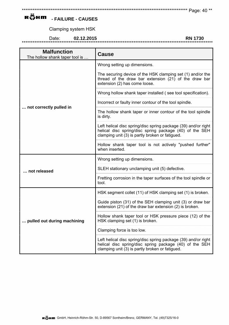
******************************************************************************************** Page: 40 **
- FAILURE - CAUSES
Clamping system HSK
Date: 02.12.2015 RN 1730 **********************************************************************************************************
GmbH, Heinrich-Röhm-Str. 50, D-89567 Sontheim/Brenz, GERMANY, Tel. (49)7325/16-0
Malfunction The hollow shank taper tool is …
Cause
… not correctly pulled in
Wrong setting up dimensions.
The securing device of the HSK clamping set (1) and/or the thread of the draw bar extension (21) of the draw bar extension (2) has come loose.
Wrong hollow shank taper installed ( see tool specification).
Incorrect or faulty inner contour of the tool spindle.
The hollow shank taper or inner contour of the tool spindle is dirty.
Left helical disc spring/disc spring package (39) and/or right helical disc spring/disc spring package (40) of the SEH clamping unit (3) is partly broken or fatigued.
Hollow shank taper tool is not actively "pushed further" when inserted.
… not released
Wrong setting up dimensions.
SLEH stationary unclamping unit (5) defective.
Fretting corrosion in the taper surfaces of the tool spindle or tool.
… pulled out during machining
HSK segment collet (11) of HSK clamping set (1) is broken.
Guide piston (31) of the SEH clamping unit (3) or draw bar extension (21) of the draw bar extension (2) is broken.
Hollow shank taper tool or HSK pressure piece (12) of the HSK clamping set (1) is broken.
Clamping force is too low.
Left helical disc spring/disc spring package (39) and/or right helical disc spring/disc spring package (40) of the SEH clamping unit (3) is partly broken or fatigued.
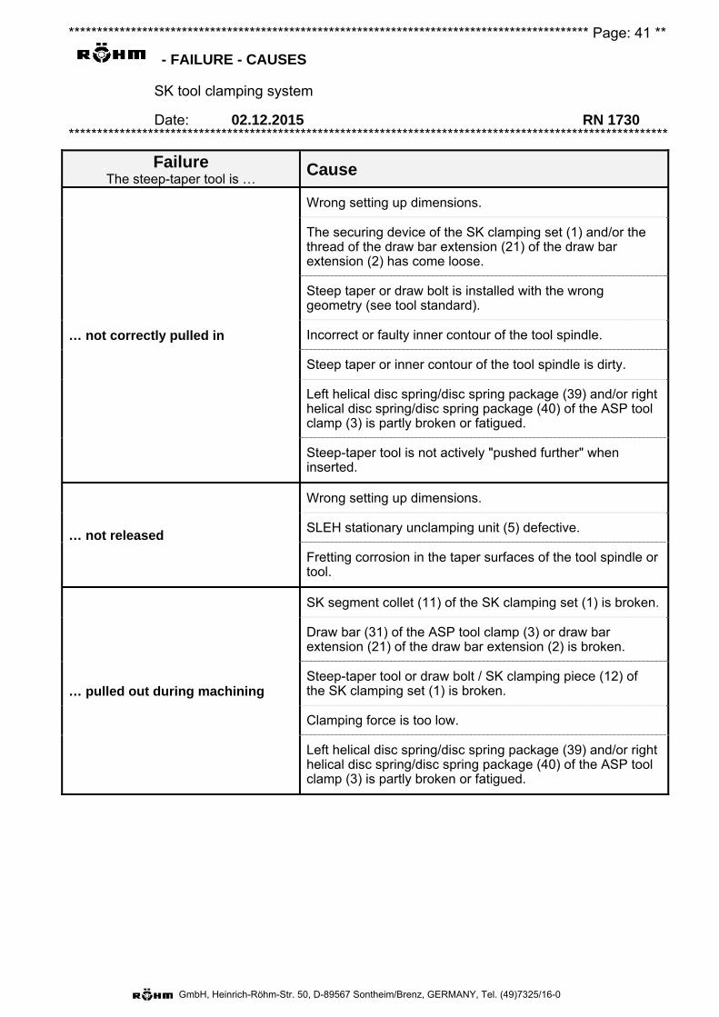
******************************************************************************************** Page: 41 **
- FAILURE - CAUSES
SK tool clamping system
Date: 02.12.2015 RN 1730 **********************************************************************************************************
GmbH, Heinrich-Röhm-Str. 50, D-89567 Sontheim/Brenz, GERMANY, Tel. (49)7325/16-0
Failure The steep-taper tool is …
Cause
… not correctly pulled in
Wrong setting up dimensions.
The securing device of the SK clamping set (1) and/or the thread of the draw bar extension (21) of the draw bar extension (2) has come loose.
Steep taper or draw bolt is installed with the wrong geometry (see tool standard).
Incorrect or faulty inner contour of the tool spindle.
Steep taper or inner contour of the tool spindle is dirty.
Left helical disc spring/disc spring package (39) and/or right helical disc spring/disc spring package (40) of the ASP tool clamp (3) is partly broken or fatigued.
Steep-taper tool is not actively "pushed further" when inserted.
… not released
Wrong setting up dimensions.
SLEH stationary unclamping unit (5) defective.
Fretting corrosion in the taper surfaces of the tool spindle or tool.
… pulled out during machining
SK segment collet (11) of the SK clamping set (1) is broken.
Draw bar (31) of the ASP tool clamp (3) or draw bar extension (21) of the draw bar extension (2) is broken.
Steep-taper tool or draw bolt / SK clamping piece (12) of the SK clamping set (1) is broken.
Clamping force is too low.
Left helical disc spring/disc spring package (39) and/or right helical disc spring/disc spring package (40) of the ASP tool clamp (3) is partly broken or fatigued.
******************************************************************************************** Page: 42 **
- Spare parts
The HSK clamping system and SK tool clamping system
Date: 02.12.2015 RN 1730 **********************************************************************************************************
GmbH, Heinrich-Röhm-Str. 50, D-89567 Sontheim/Brenz, GERMANY, Tel. (49)7325/16-0
Please note that only ORIGINAL RÖHM spare parts or components acquired from suppliers authorized by Röhm GmbH should be used. MESSRS. RÖHM will not accept any liability for any damage caused by the use of components provided by other suppliers.
Note: Details of the 6-digit identity number engraved on the module and the manufacturing number (if available) are required to facilitate spare parts or individual components ordering. The manufacturing number consists of a letter followed by 2 numbers and, possibly, an incremental number, this being either on the nameplate or in the near vicinity of the identity number.
Manufacturer's address: Firm
RÖHM GmbH Heinrich-Röhm-Str. 50 89567 Sontheim /Brenz GERMANY
******************************************************************************************** Page: 43 **
- Warranty exclusions
The HSK clamping system and SK tool clamping system
Date: 02.12.2015 RN 1730 **********************************************************************************************************
GmbH, Heinrich-Röhm-Str. 50, D-89567 Sontheim/Brenz, GERMANY, Tel. (49)7325/16-0
The warranty of the seller does not include damage or deficiencies
1. caused by the user due to non-compliance with the written instructions of the seller with regard to commissioning (e.g. deficient construction and installation work), the operation and the maintenance of the equipment (as far as this maintenance is not taken over by the manufacturer as part of a contractual agreement).
2. caused by technical operating conditions (e.g. chemical or electrolytic influences) and/or machine data unknown to the manufacturer.
3. caused by natural wear.
4. caused by forces of nature.
5. caused by erroneous operation of any sort or caused by improper use or operation of the clamping device or part thereof. This also includes loading beyond the specified load limits (e.g. speed, pressure, force, etc.).
6. which are not our responsibility. This also includes damage caused when the customer or third parties make modifications or repairs to the manufacturer's work/products without having the previous written permission of the manufacturer. Excluded from this are damage and deficiencies proven not to be caused by these modifications or repairs.
7. which occur during use of the system/installation or parts thereof under altered operating conditions (e.g. materials, tools, cutting parameters, programs, etc.), in particular without consultation with and written release by the seller or the manufacturer.
8. which were caused by altered environmental conditions.
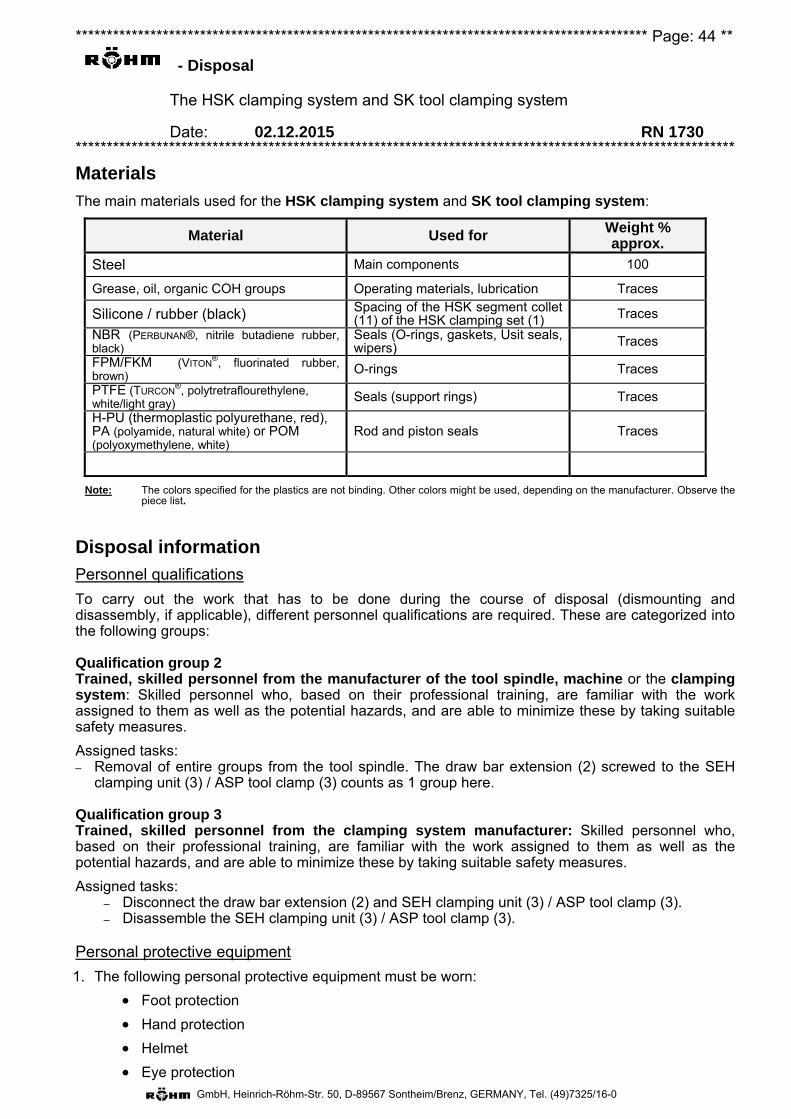
******************************************************************************************** Page: 44 **
- Disposal
The HSK clamping system and SK tool clamping system
Date: 02.12.2015 RN 1730 **********************************************************************************************************
GmbH, Heinrich-Röhm-Str. 50, D-89567 Sontheim/Brenz, GERMANY, Tel. (49)7325/16-0
Materials
The main materials used for the HSK clamping system and SK tool clamping system:
Material Used for Weight % approx.
Steel Main components 100
Grease, oil, organic COH groups Operating materials, lubrication Traces
Silicone / rubber (black) Spacing of the HSK segment collet (11) of the HSK clamping set (1) Traces
NBR (PERBUNAN®, nitrile butadiene rubber, black)
Seals (O-rings, gaskets, Usit seals, wipers) Traces
FPM/FKM (VITON®, fluorinated rubber,
brown) O-rings Traces
PTFE (TURCON®, polytretraflourethylene,
white/light gray) Seals (support rings) Traces
H-PU (thermoplastic polyurethane, red), PA (polyamide, natural white) or POM (polyoxymethylene, white)
Rod and piston seals Traces
Note: The colors specified for the plastics are not binding. Other colors might be used, depending on the manufacturer. Observe the piece list.
Disposal information
Personnel qualifications
To carry out the work that has to be done during the course of disposal (dismounting and disassembly, if applicable), different personnel qualifications are required. These are categorized into the following groups:
Qualification group 2 Trained, skilled personnel from the manufacturer of the tool spindle, machine or the clamping system: Skilled personnel who, based on their professional training, are familiar with the work assigned to them as well as the potential hazards, and are able to minimize these by taking suitable safety measures.
Assigned tasks: – Removal of entire groups from the tool spindle. The draw bar extension (2) screwed to the SEH
clamping unit (3) / ASP tool clamp (3) counts as 1 group here.
Qualification group 3 Trained, skilled personnel from the clamping system manufacturer: Skilled personnel who, based on their professional training, are familiar with the work assigned to them as well as the potential hazards, and are able to minimize these by taking suitable safety measures.
Assigned tasks: – Disconnect the draw bar extension (2) and SEH clamping unit (3) / ASP tool clamp (3). – Disassemble the SEH clamping unit (3) / ASP tool clamp (3).
Personal protective equipment
1. The following personal protective equipment must be worn:
Foot protection
Hand protection
Helmet
Eye protection
******************************************************************************************** Page: 45 **
- Disposal
The HSK clamping system and SK tool clamping system
Date: 02.12.2015 RN 1730 **********************************************************************************************************
GmbH, Heinrich-Röhm-Str. 50, D-89567 Sontheim/Brenz, GERMANY, Tel. (49)7325/16-0
Measures (qualification group 2)
1. Dismount the HSK clamping system / SK tool clamping system. Please refer to the chapter"Dismounting".
Important: The SEH clamping unit (3) / ASP tool clamp (3) and the draw bar extension (2) may notbe screwed apart here.
2. Before disposal, the SLEH stationary unclamping unit (5) must be drained. The accumulatedhydraulic oil must be disposed of with the waste oil or recycled according to the local regulations.
3. As long as the installed seals (made of various plastics) don't have to be disposed of separately,all components of the HSK clamping system or SK tool clamping system can be disposed of inthe usual steel scrap.
Danger: The SEH clamping unit (3) / ASP tool clamp (3) and the draw bar extension (2) may only be screwed apart by the manufacturer! The SEH clamping unit (3) / ASP tool clamp (3) may only be disassembled by the manufacturer!
Measures (qualification group 3)
1. The HSK clamping system / SK tool clamping system must already be dismounted. See also the"Dismounting" chapter.
2. If even the smallest traces of foreign (e.g. non-magnetic) substances have to be separated due toany locally valid regulations, then the entire drained HSK clamping system or the entire drainedSK tool clamping system must be disassembled and separated into its different materials beforedisposal and disposed of separately according to the used materials (see list above or piece list).
3. If the HSK clamping system or the SK tool clamping system is disassembled, individual itemsfrom the chapter "General warnings" must be observed (operator qualification, dangers of injury(partially), environmental hazards).
KOB Sontheim, issued: 28.06.2016
Ejection stroke Setting dimension