Embed Size (px)
DESCRIPTION
Radiographic testing
Citation preview
Duties of a Radiographic InterpreterDuties of a Radiographic Interpreter
Mask of any unwanted light from viewer
Ensure the background light is subdued
Check the radiograph for correct
identification
Assess the radiographs density
Calculate the radiographs sensitivity
Check the radiograph for any artifacts
Assess the radiograph for any defects
present
State the action to be taken, acceptable,
rejectable or repair
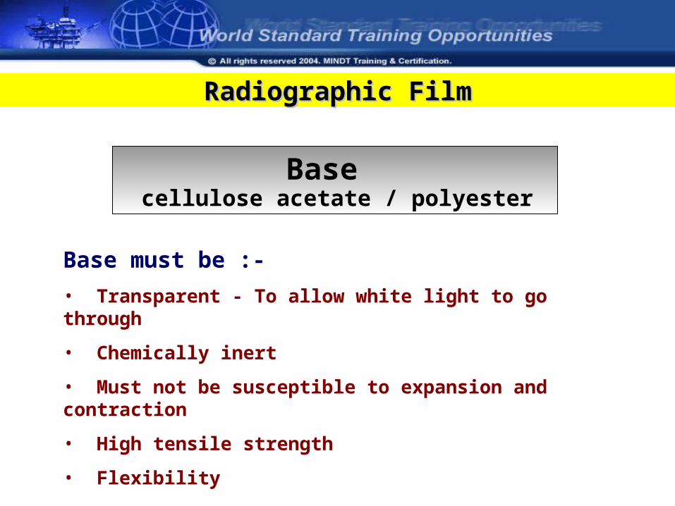
Radiographic FilmRadiographic Film
Base
Base must be :-
• Transparent - To allow white light to go through
• Chemically inert
• Must not be susceptible to expansion and contraction
• High tensile strength
• Flexibility
cellulose acetate / polyester
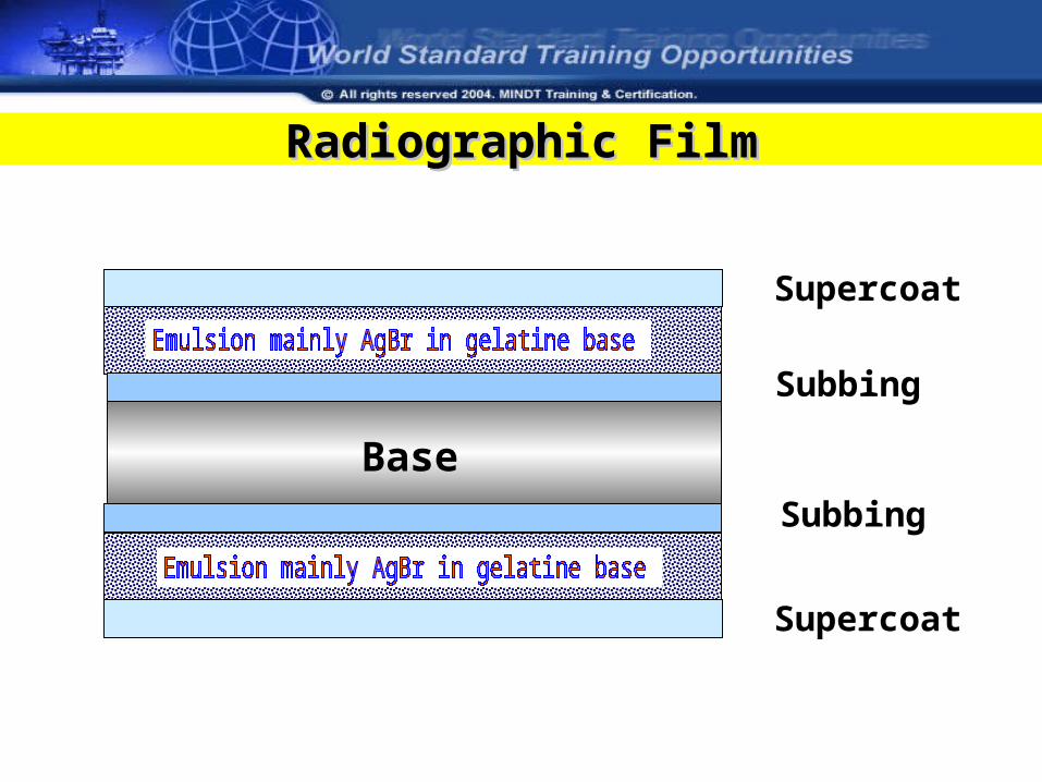
Base
Supercoat
Supercoat
Subbing
Subbing
Radiographic FilmRadiographic Film
What are the advantages of Double Coated Film?
• Improve contrast
• Reduce the exposure time
Radiographic FilmRadiographic Film
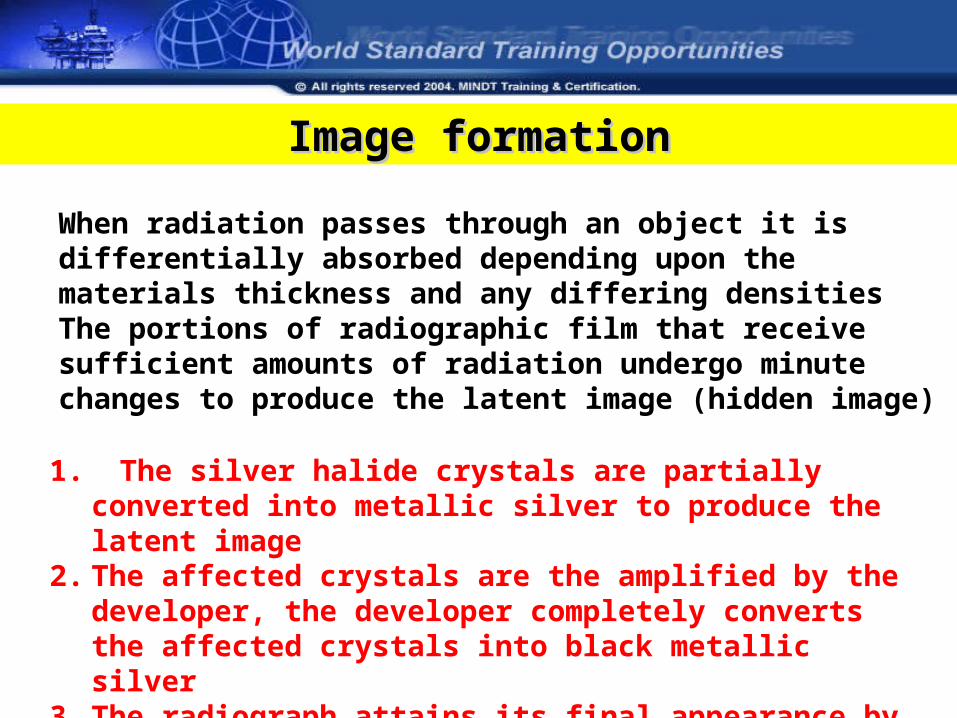
Image formationImage formation
When radiation passes through an object it is differentially absorbed depending upon the materials thickness and any differing densitiesThe portions of radiographic film that receive sufficient amounts of radiation undergo minute changes to produce the latent image (hidden image)
1. The silver halide crystals are partially converted into metallic silver to produce the latent image
2. The affected crystals are the amplified by the developer, the developer completely converts the affected crystals into black metallic silver
3. The radiograph attains its final appearance by fixation
Film Types
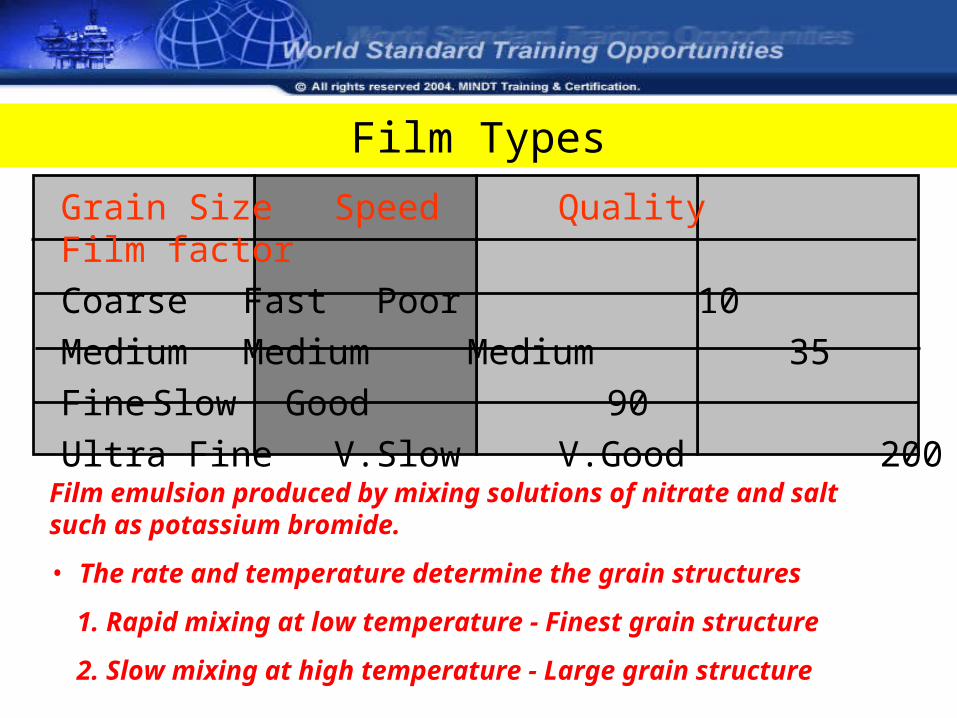
Grain SizeSpeed Quality Film factor Coarse Fast Poor 10Medium Medium Medium 35Fine Slow Good 90Ultra Fine V.Slow V.Good 200
Film emulsion produced by mixing solutions of nitrate and salt such as potassium bromide.
• The rate and temperature determine the grain structures
1. Rapid mixing at low temperature - Finest grain structure
2. Slow mixing at high temperature - Large grain structure
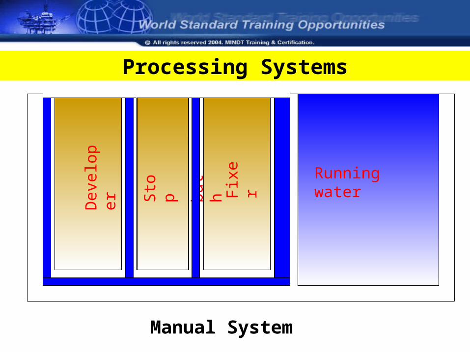
Dev
elop
er
Sto
p
bath
Fix
er Running water
Processing Systems
Manual System
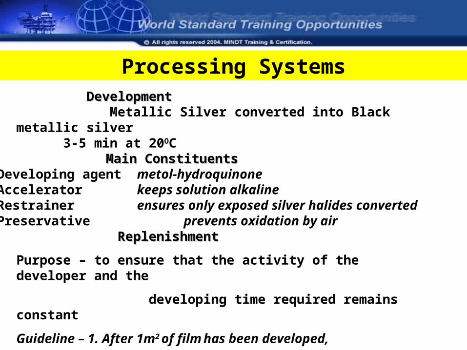
DevelopmentDevelopment Metallic Silver converted into Black metallic silver
3-5 min at 20OC
Main ConstituentsMain ConstituentsDeveloping agent metol-hydroquinoneAccelerator keeps solution alkalineRestrainer ensures only exposed silver halides convertedPreservative prevents oxidation by air
Processing Systems
Replenishment Replenishment
Purpose – to ensure that the activity of the developer and the
developing time required remains constant
Guideline – 1. After 1m2 of film has been developed,
about 400 ml of replenisher needs to be added
FixerFixer
• Sodium thiosulphate or ammonium thiosulphate Functions:- 1. Removes all unexposed silver grains 2. Hardens the emulsion gelatin
• Clearing time - The time taken for the radiography to loose its milky appearance.
• Fixing time - Twice the clearing time
Processing Systems
Processing Systems
Running waterRunning water
• Films should be washed in a tank with constant running water for at least 20 minutes.
• Insufficient washing the film can caused the yellow fog appears.
Characteristic CurvesCharacteristic Curves
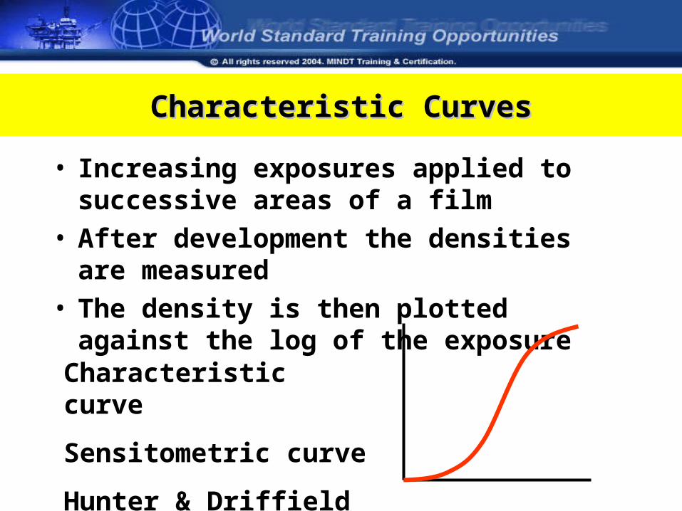
• Increasing exposures applied to successive areas of a film
• After development the densities are measured• The density is then plotted against the log of the
exposure
Characteristic curve
Sensitometric curve
Hunter & Driffield curve
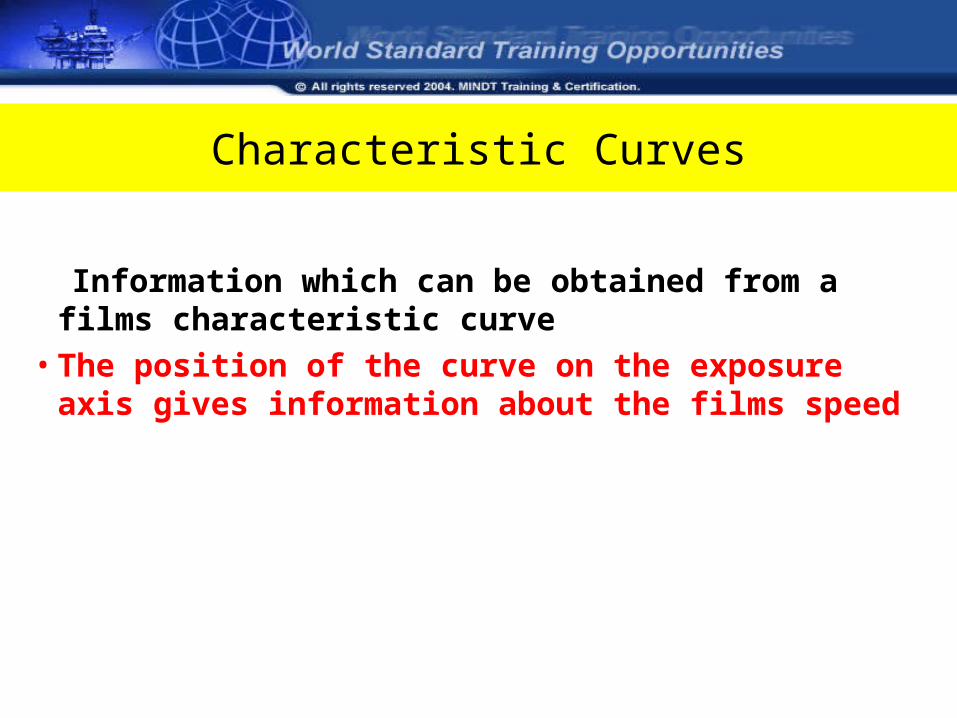
Characteristic Curves
Information which can be obtained from a films characteristic curve
• The position of the curve on the exposure axis gives information about the films speed
• The gradient of the curve gives information on the films contrast
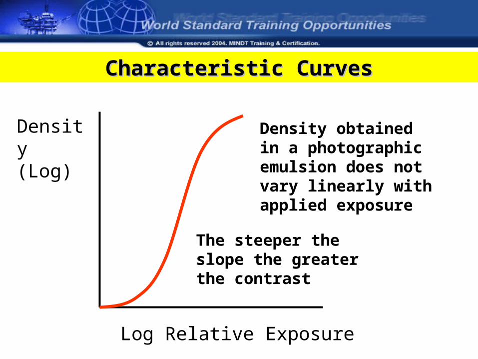
Characteristic CurvesCharacteristic Curves
Log Relative Exposure
Density (Log)
Density obtained in a photographic emulsion does not vary linearly with applied exposure
The steeper the slope the greater the contrast
Characteristic Curves
Information which can be obtained from a films characteristic curve
• The position of the curve on the exposure axis gives information about the films speed
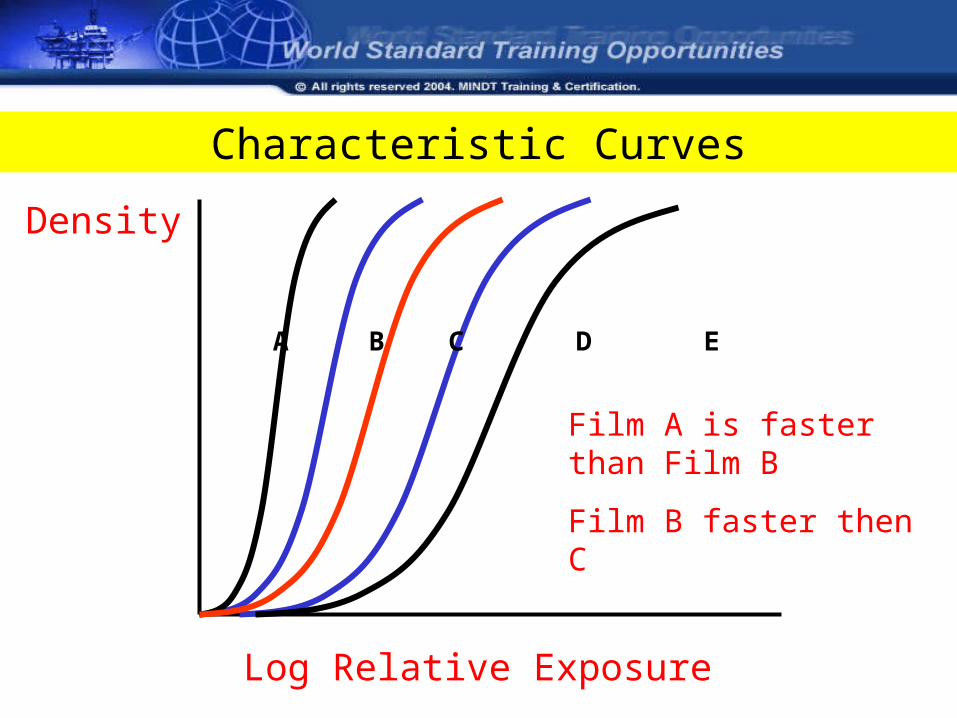
Characteristic Curves
Log Relative Exposure
Density
A B C D E
Film A is faster than Film B
Film B faster then C
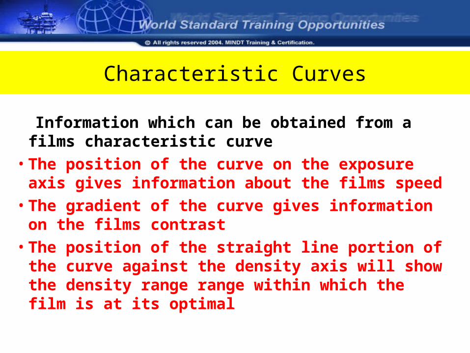
Characteristic Curves
Information which can be obtained from a films characteristic curve
• The position of the curve on the exposure axis gives information about the films speed
• The gradient of the curve gives information on the films contrast
• The position of the straight line portion of the curve against the density axis will show the density range range within which the film is at its optimal
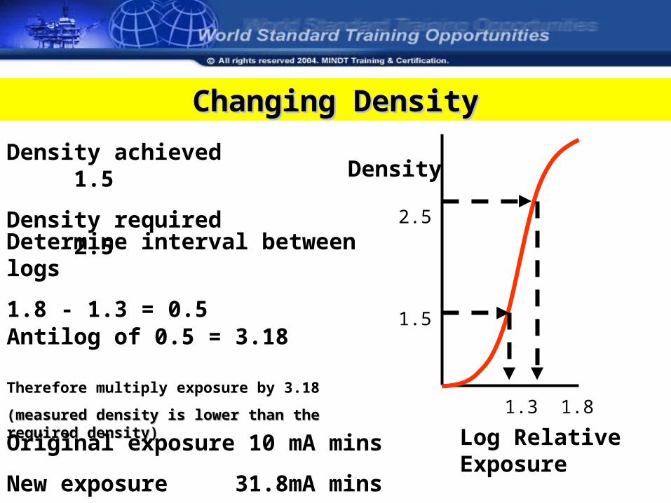
Changing DensityChanging Density
Log Relative Exposure
DensityDensity achieved 1.5
Density required 2.5
Determine interval between logs
1.8 - 1.3 = 0.5
2.5
1.5
1.3 1.8
Antilog of 0.5 = 3.18
Therefore multiply exposure by 3.18
(measured density is lower than the required density)(measured density is lower than the required density)
Original exposure 10 mA mins
New exposure 31.8mA mins
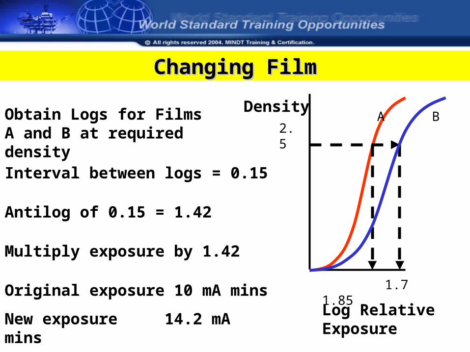
Changing FilmChanging Film
Log Relative Exposure
DensityObtain Logs for Films A and B at required density
Interval between logs = 0.15
1.7 1.85
Antilog of 0.15 = 1.42
Multiply exposure by 1.42
Original exposure 10 mA mins
New exposure 14.2 mA mins
2.5 A B
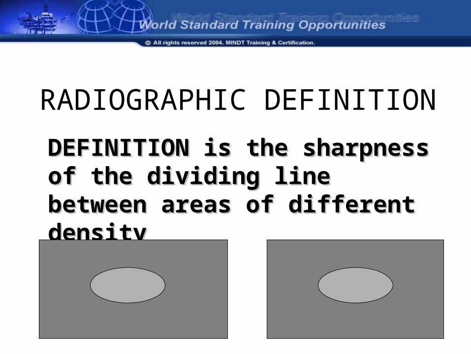
RADIOGRAPHIC DEFINITION
DEFINITION is the sharpness of the DEFINITION is the sharpness of the dividing line between areas of dividing line between areas of different densitydifferent density
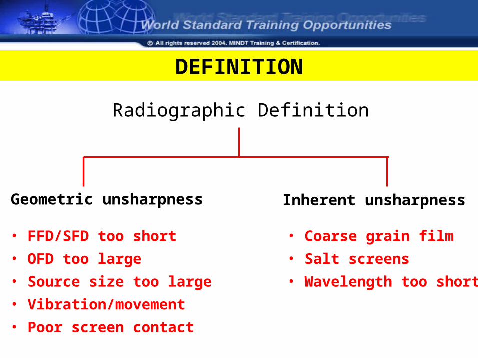
Radiographic Definition
Geometric unsharpness Inherent unsharpness
• FFD/SFD too short
• OFD too large
• Source size too large
• Vibration/movement
• Poor screen contact
• Coarse grain film
• Salt screens
• Wavelength too short
DEFINITION
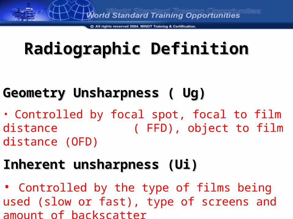
Geometry Unsharpness ( Ug)Geometry Unsharpness ( Ug)
• Controlled by focal spot, focal to film distance ( FFD), object to film distance (OFD)
Inherent unsharpness (Ui) Inherent unsharpness (Ui)
• Controlled by the type of films being used (slow or fast), type of screens and amount of backscatter
Radiographic DefinitionRadiographic Definition
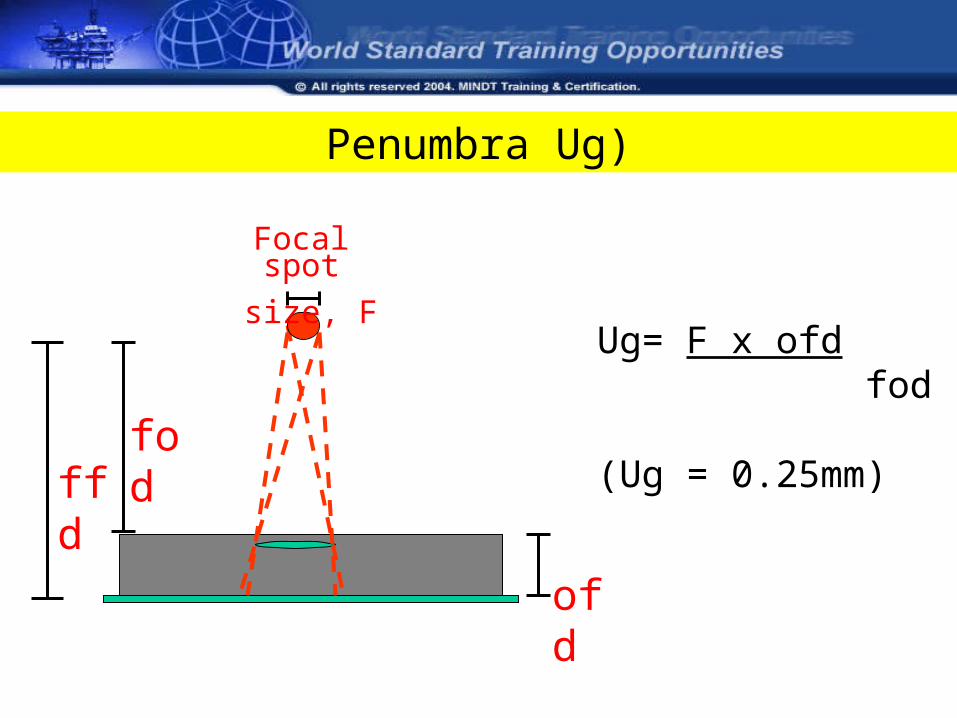
Penumbra Ug)
Ug= F x ofd fod
(Ug = 0.25mm)
ofd
Focal spot
size, F
fodffd
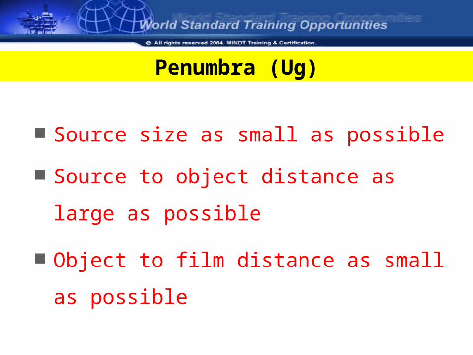
Source size as small as possible
Source to object distance as large as
possible
Object to film distance as small as
possible
Penumbra (Ug)
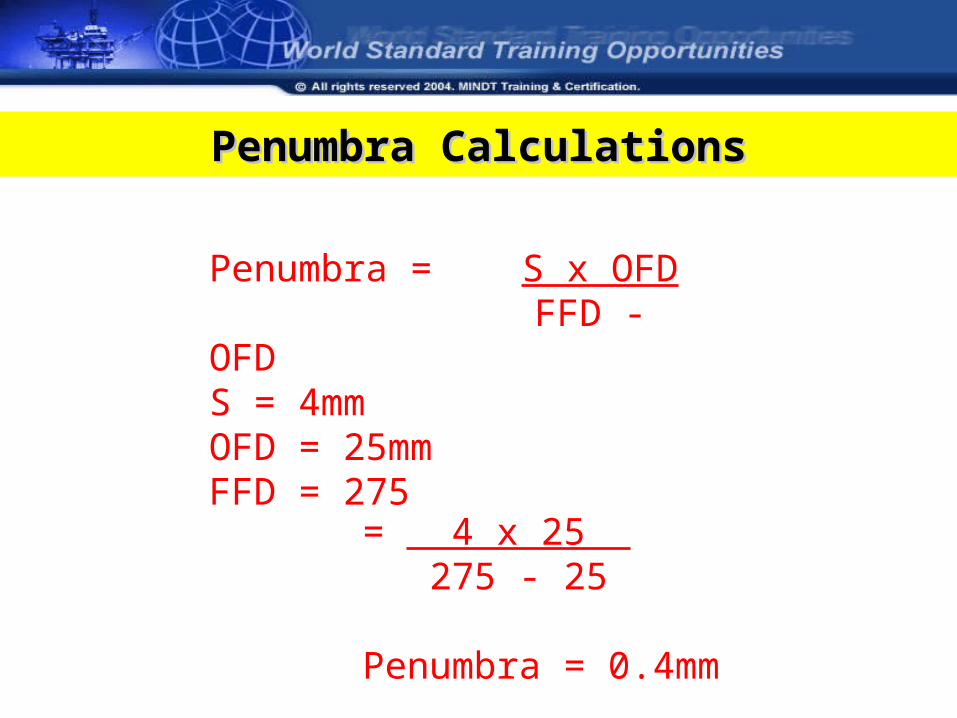
Penumbra = S x OFD FFD - OFD
S = 4mmOFD = 25mmFFD = 275
= 4 x 25 275 - 25
Penumbra = 0.4mm
Penumbra CalculationsPenumbra Calculations
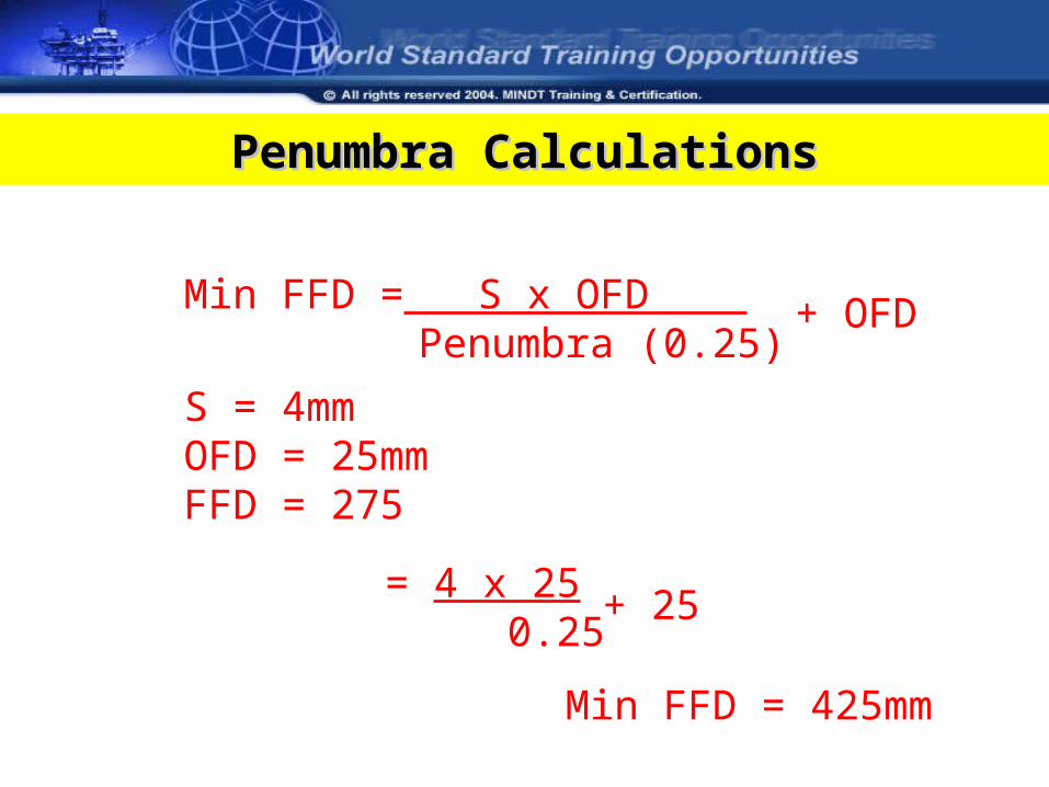
Penumbra CalculationsPenumbra Calculations
= 4 x 25 0.25
+ 25
Min FFD = S x OFD Penumbra (0.25)
S = 4mmOFD = 25mmFFD = 275
+ OFD
Min FFD = 425mm
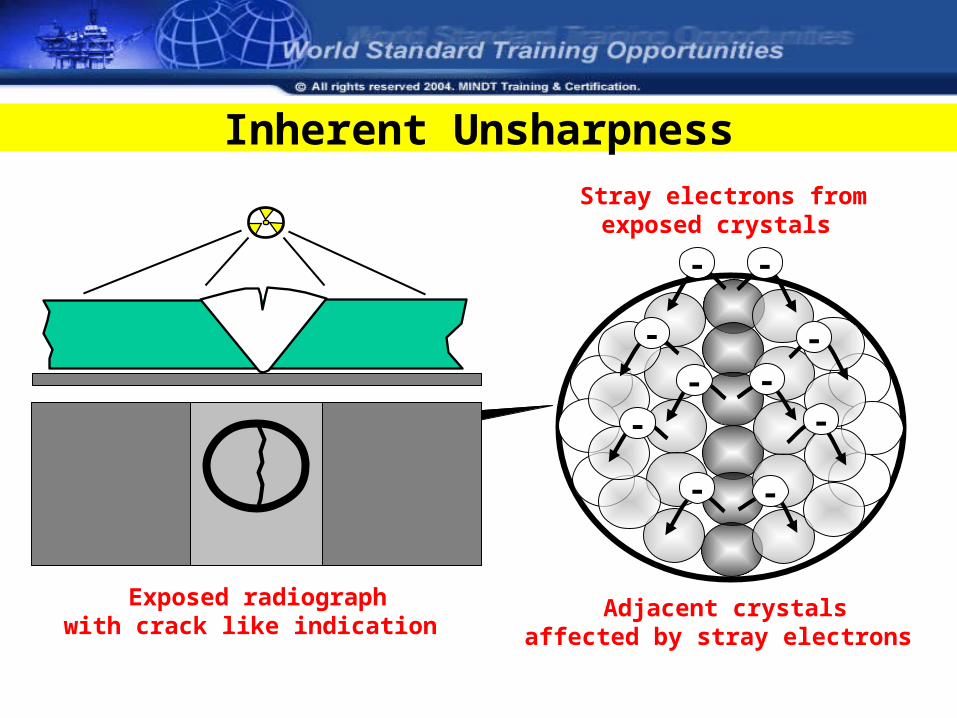
Inherent Unsharpness
Exposed radiographwith crack like indication
Stray electrons fromexposed crystals
Adjacent crystalsaffected by stray electrons
- -
-
--
-
-
- -
-
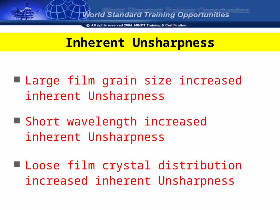
Inherent Unsharpness
Large film grain size increased inherent Unsharpness
Short wavelength increased inherent Unsharpness
Loose film crystal distribution increased inherent Unsharpness
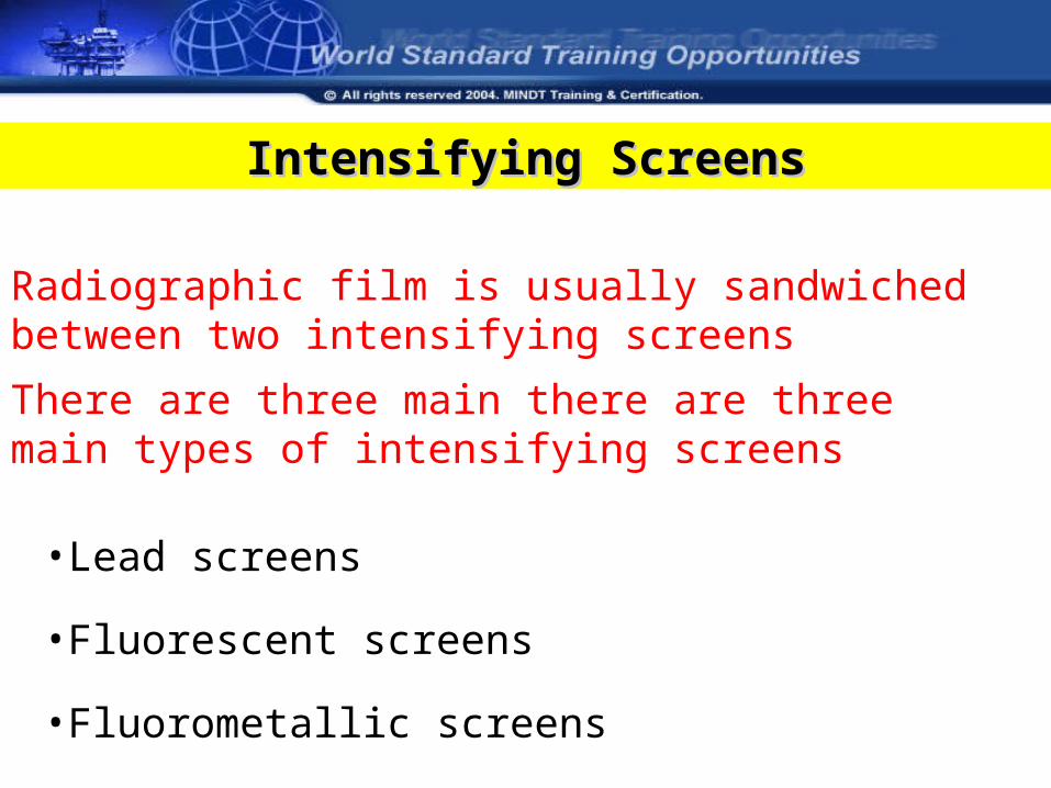
Intensifying ScreensIntensifying Screens
Radiographic film is usually sandwiched between two intensifying screens
There are three main there are three main types of intensifying screens
•Lead screens
•Fluorescent screens
•Fluorometallic screens
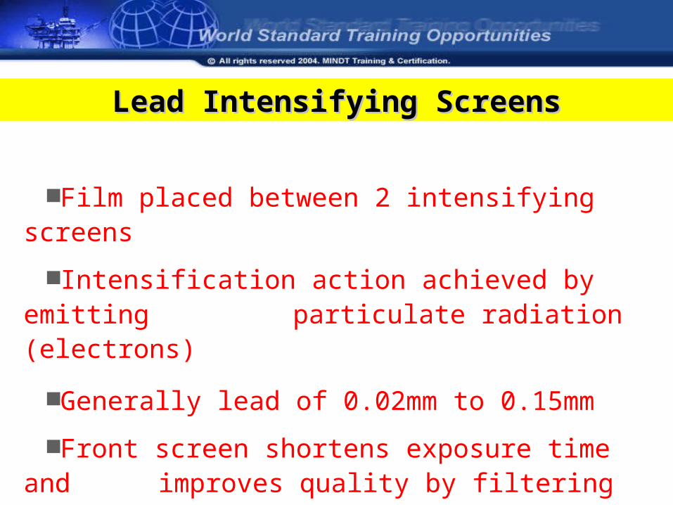
Film placed between 2 intensifying screens
Intensification action achieved by emitting particulate radiation (electrons)
Generally lead of 0.02mm to 0.15mm
Front screen shortens exposure time and improves quality by filtering out scatter
Back screen acts as a filter only
Lead Intensifying ScreensLead Intensifying Screens
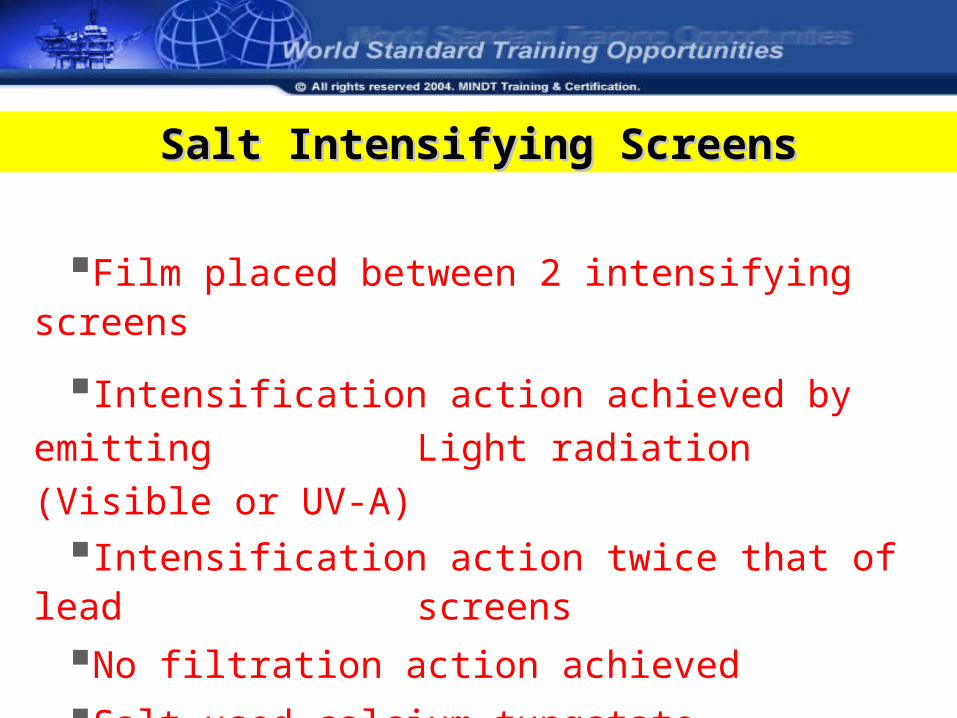
Film placed between 2 intensifying screens
Intensification action achieved by emitting
Light radiation (Visible or UV-A)
Intensification action twice that of lead screens
No filtration action achieved
Salt used calcium tungstate
Salt Intensifying ScreensSalt Intensifying Screens
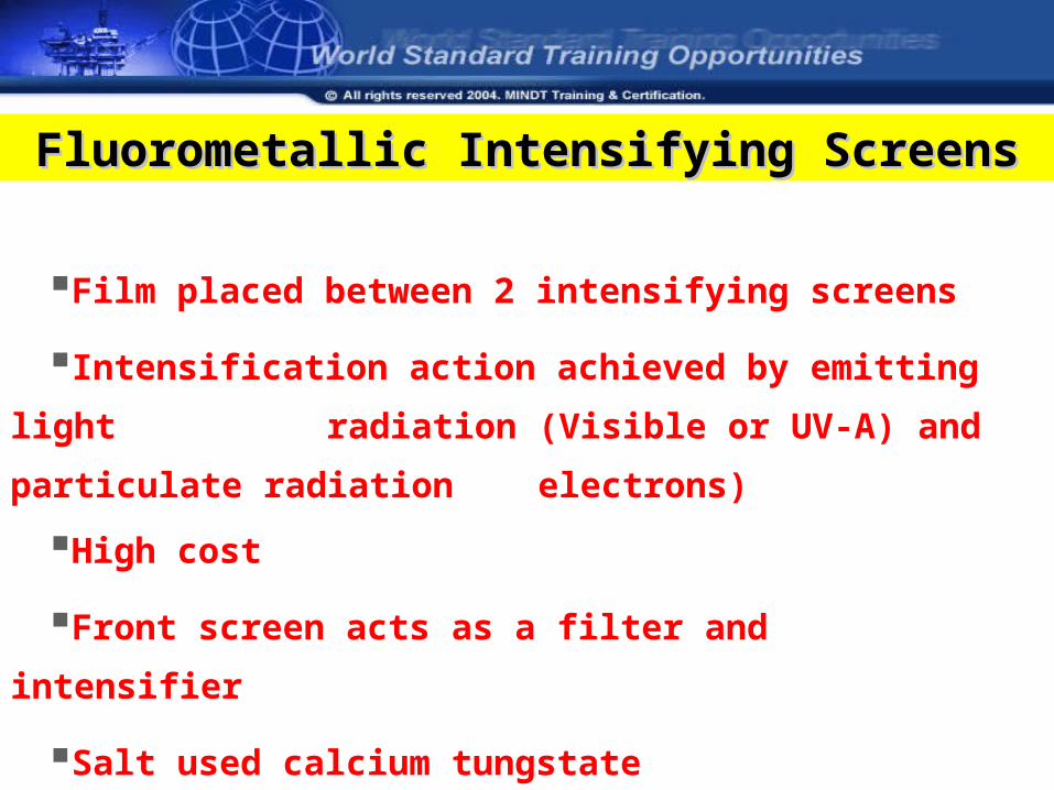
Film placed between 2 intensifying screens
Intensification action achieved by emitting light
radiation (Visible or UV-A) and particulate radiation
electrons)
High cost
Front screen acts as a filter and intensifier
Salt used calcium tungstate
Fluorometallic Intensifying ScreensFluorometallic Intensifying Screens
ScatterScatter
• Radiation emitted from any other source than that giving the primary desired rectilinear propagation
• Scatter will lead to poorer contrast and definition and create spurious indications
• It may also cause radiological protection problems
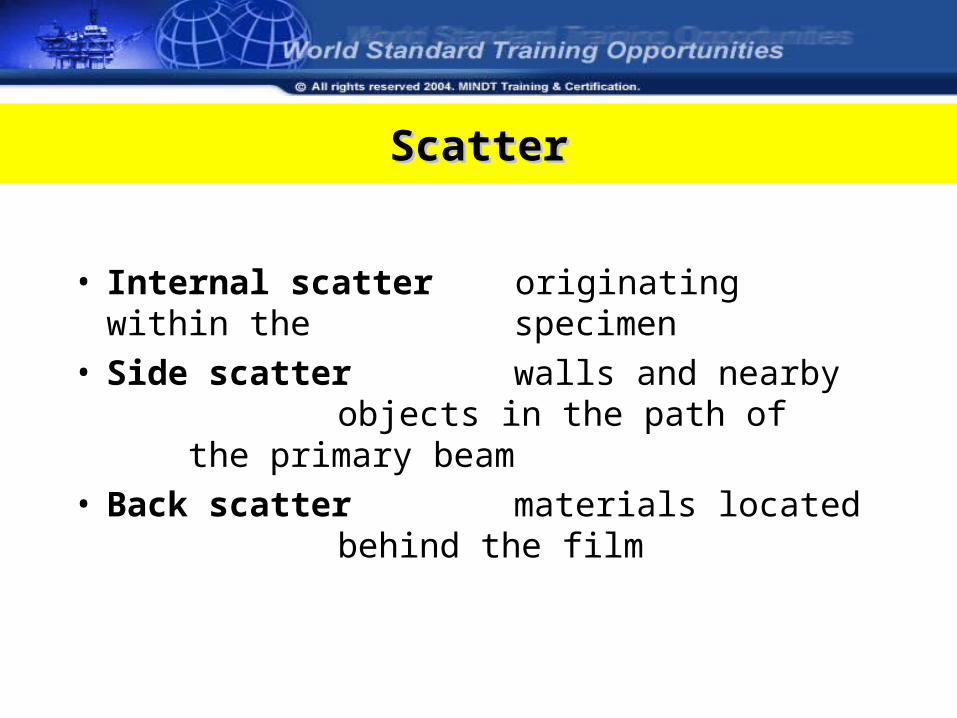
ScatterScatter
• Internal scatter originating within the specimen
• Side scatter walls and nearby objects in the path of
the primary beam• Back scatter materials located
behind the film
Control of ScatterControl of Scatter
• Collimation
• Protection from back scatter
• Beam filtration
• Blocking
• Grids
• Increased beam energy
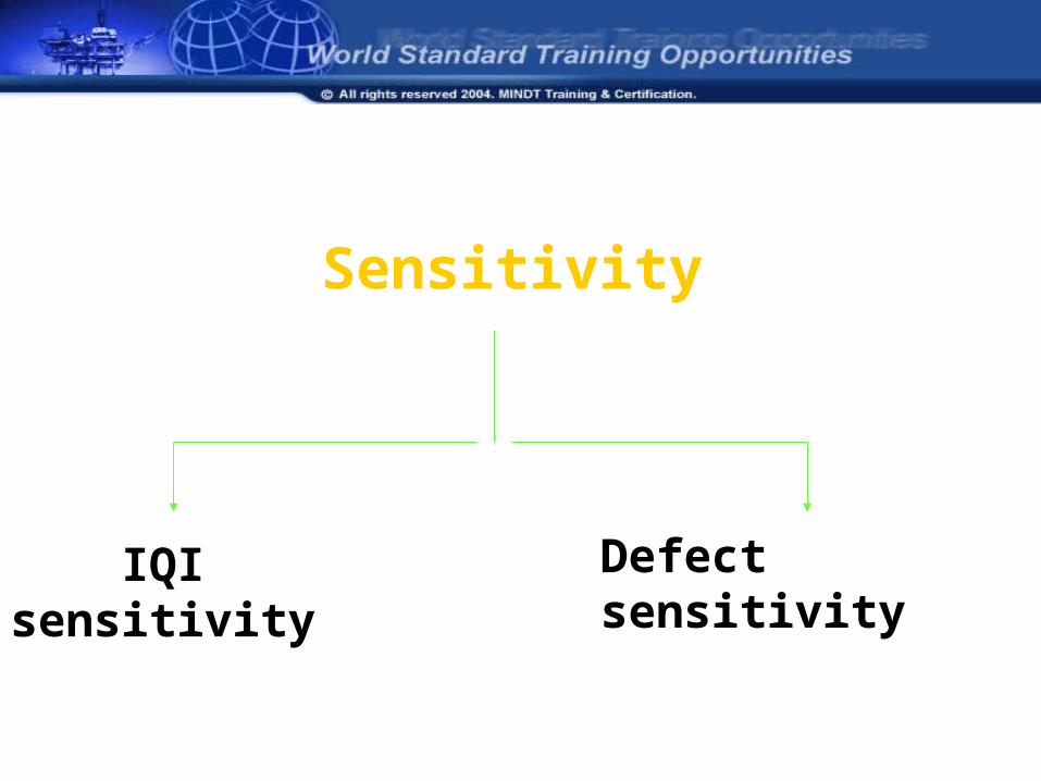
Sensitivity
IQI sensitivity Defect sensitivity
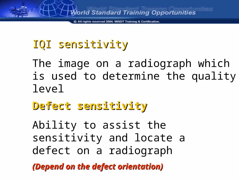
IQI sensitivityIQI sensitivity
The image on a radiograph which is used to determine the quality level
Defect sensitivity Defect sensitivity
Ability to assist the sensitivity and locate a defect on a radiograph
(Depend on the defect orientation)(Depend on the defect orientation)
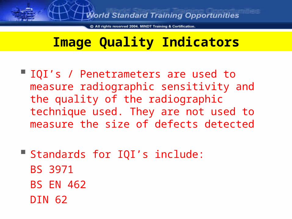
Image Quality Indicators
IQI’s / Penetrameters are used to measure radiographic sensitivity and the quality of the radiographic technique used. They are not used to measure the size of defects detected
Standards for IQI’s include:
BS 3971
BS EN 462
DIN 62
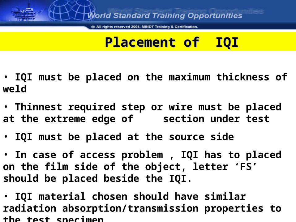
Placement of IQIPlacement of IQI
• IQI must be placed on the maximum thickness of weld
• Thinnest required step or wire must be placed at the extreme edge of section under test
• IQI must be placed at the source side
• In case of access problem , IQI has to placed on the film side of the object, letter ‘FS’ should be placed beside the IQI.
• IQI material chosen should have similar radiation absorption/transmission properties to the test specimen
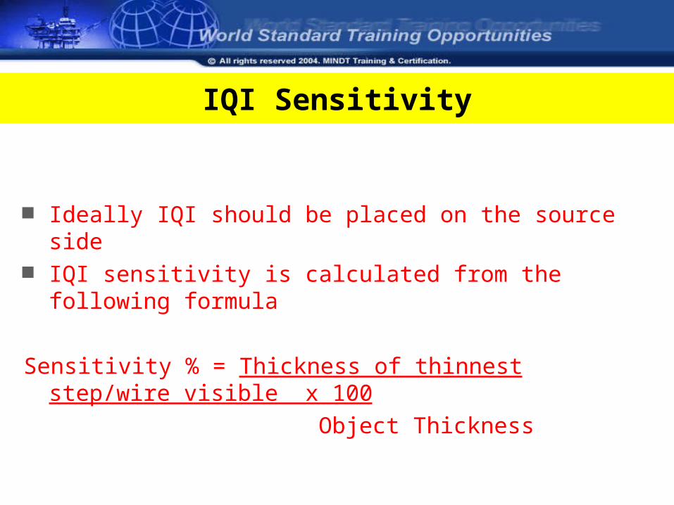
Ideally IQI should be placed on the source side IQI sensitivity is calculated from the following formula
Sensitivity % = Thickness of thinnest step/wire visible x 100
Object Thickness
IQI Sensitivity
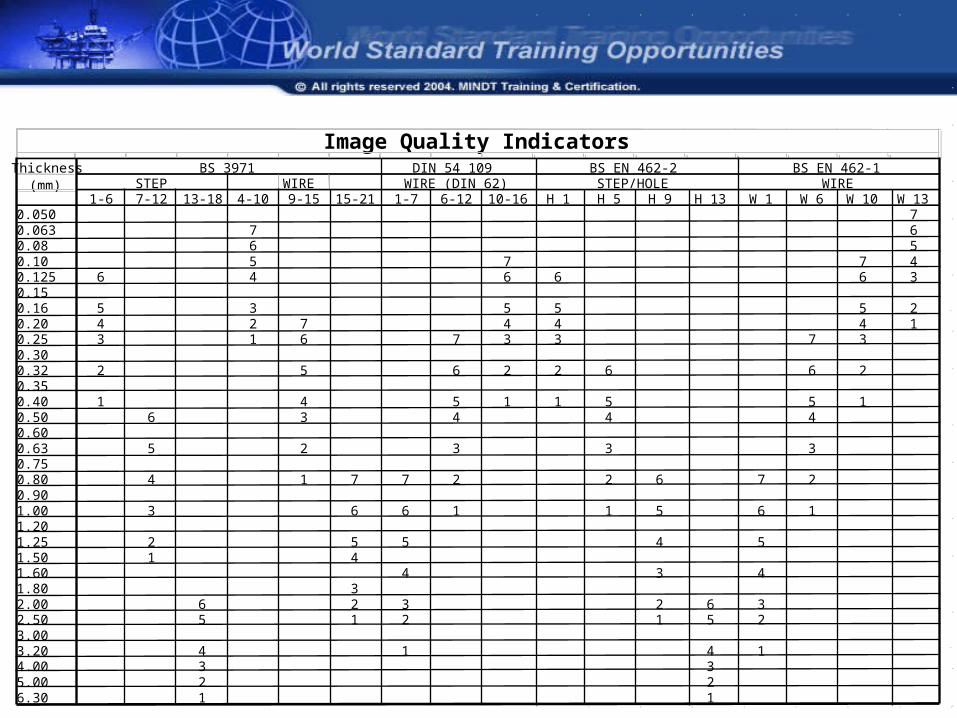
Image Quality IndicatorsThickness BS 3971 DIN 54 109 BS EN 462-2 BS EN 462-1
(mm) STEP WIRE WIRE (DIN 62) STEP/HOLE WIRE1-6 7-12 13-18 4-10 9-15 15-21 1-7 6-12 10-16 H 1 H 5 H 9 H 13 W 1 W 6 W 10 W 13
0.050 70.063 7 60.08 6 50.10 5 7 7 40.125 6 4 6 6 6 30.150.16 5 3 5 5 5 20.20 4 2 7 4 4 4 10.25 3 1 6 7 3 3 7 30.300.32 2 5 6 2 2 6 6 20.350.40 1 4 5 1 1 5 5 10.50 6 3 4 4 40.600.63 5 2 3 3 30.750.80 4 1 7 7 2 2 6 7 20.901.00 3 6 6 1 1 5 6 11.201.25 2 5 5 4 51.50 1 41.60 4 3 41.80 32.00 6 2 3 2 6 32.50 5 1 2 1 5 23.003.20 4 1 4 14.00 3 35.00 2 26.30 1 1
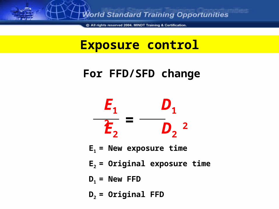
For FFD/SFD change
E1 D1 2
E2 D2 2=
E1 = New exposure time
E2 = Original exposure time
D1 = New FFD
D2 = Original FFD
Exposure control
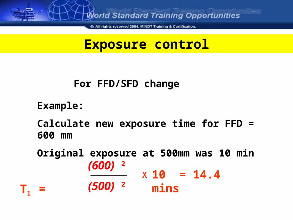
For FFD/SFD change
Example:
Calculate new exposure time for FFD = 600 mm
Original exposure at 500mm was 10 min
T1 =(600) 2
(500) 2 X 10 = 14.4 mins
Exposure control
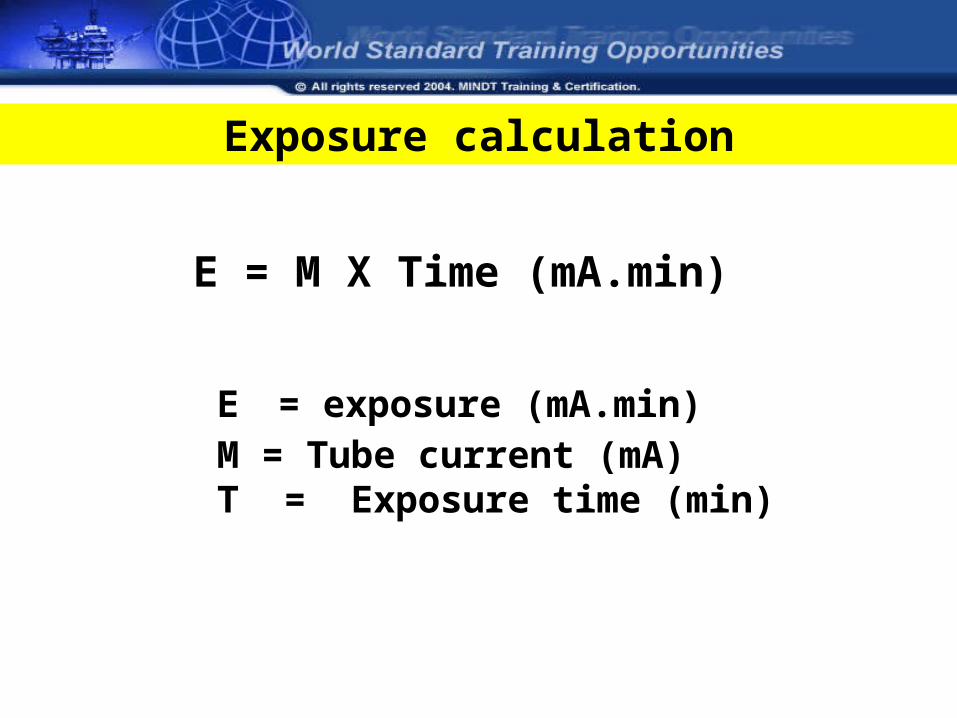
Exposure calculation
E = M X Time (mA.min)
E = exposure (mA.min)M = Tube current (mA)T = Exposure time (min)
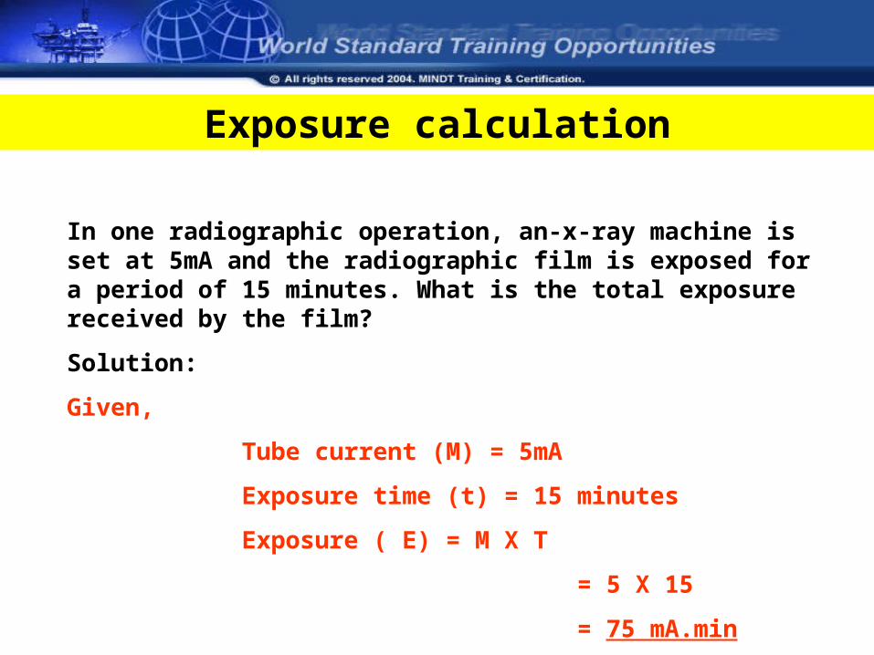
Exposure calculation
In one radiographic operation, an-x-ray machine is set at 5mA and the radiographic film is exposed for a period of 15 minutes. What is the total exposure received by the film?
Solution:
Given,
Tube current (M) = 5mA
Exposure time (t) = 15 minutes
Exposure ( E) = M X T
= 5 X 15
= 75 mA.min
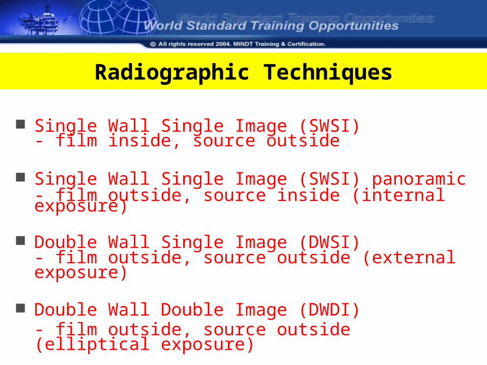
Radiographic Techniques
Single Wall Single Image (SWSI)- film inside, source outside
Single Wall Single Image (SWSI) panoramic- film outside, source inside (internal exposure)
Double Wall Single Image (DWSI)- film outside, source outside (external exposure)
Double Wall Double Image (DWDI)- film outside, source outside (elliptical exposure)
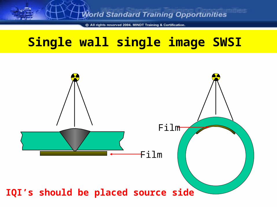
Single wall single image SWSI
IQI’s should be placed source side
Film
Film
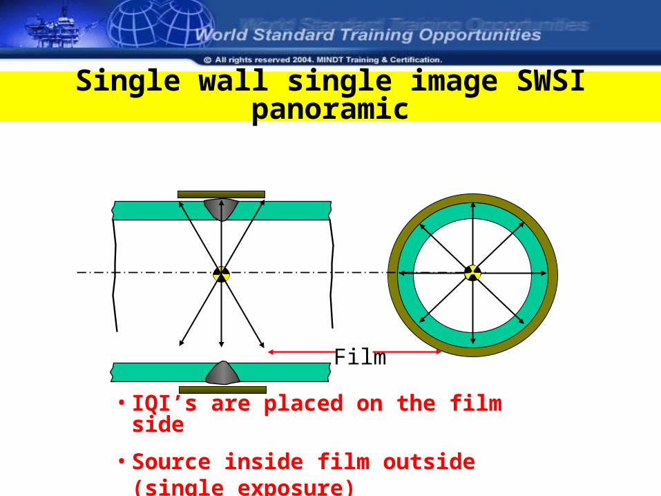
Single wall single image SWSI panoramic
• IQI’s are placed on the film side
• Source inside film outside (single exposure)
Film
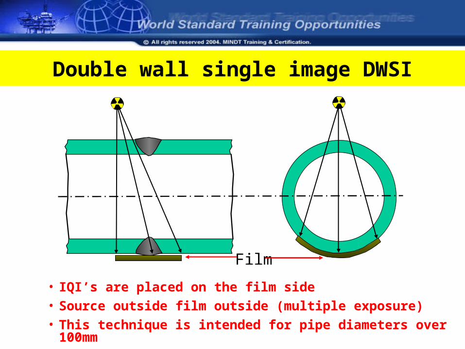
Double wall single image DWSI
• IQI’s are placed on the film side
• Source outside film outside (multiple exposure)
• This technique is intended for pipe diameters over 100mm
Film
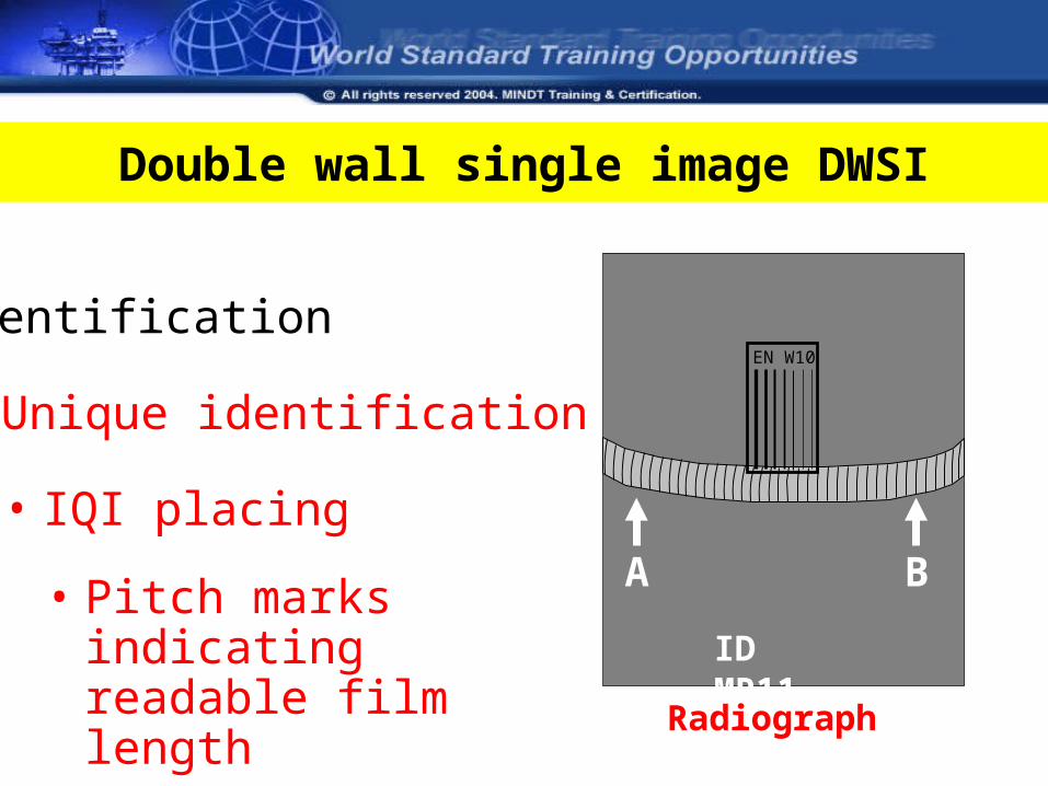
Double wall single image DWSI
Radiograph
Identification
ID MR11
• Unique identification
EN W10
• IQI placingA B• Pitch marks indicating
readable film length
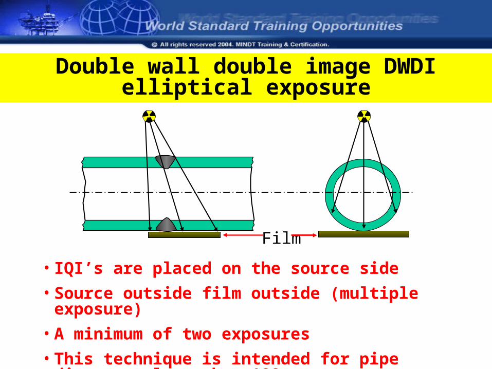
Double wall double image DWDI elliptical exposure
Film
• IQI’s are placed on the source side
• Source outside film outside (multiple exposure)
• A minimum of two exposures
• This technique is intended for pipe diameters less than 100mm
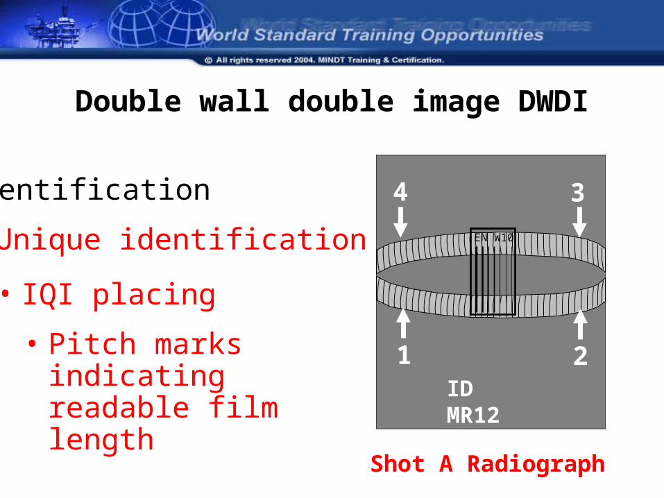
Double wall double image DWDI
Shot A Radiograph
Identification
ID MR12
• Unique identification EN W10
• IQI placing
1 2• Pitch marks indicating readable film length
4 3
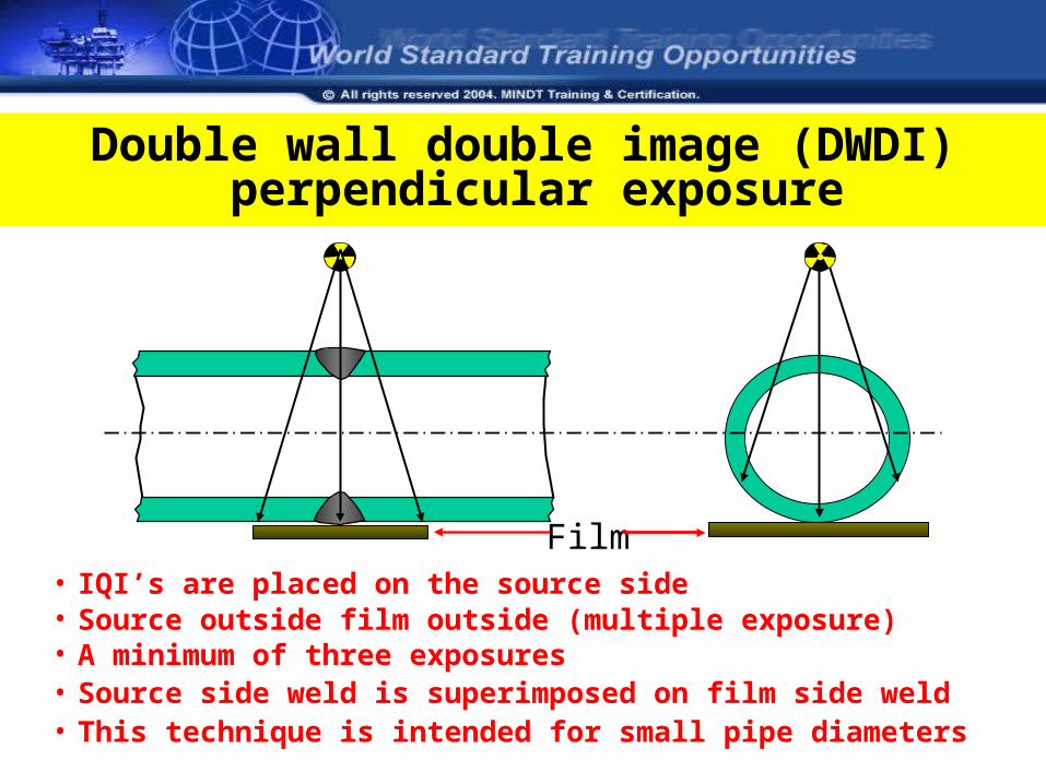
Double wall double image (DWDI) perpendicular exposure
Film• IQI’s are placed on the source side• Source outside film outside (multiple exposure)• A minimum of three exposures• Source side weld is superimposed on film side weld• This technique is intended for small pipe diameters
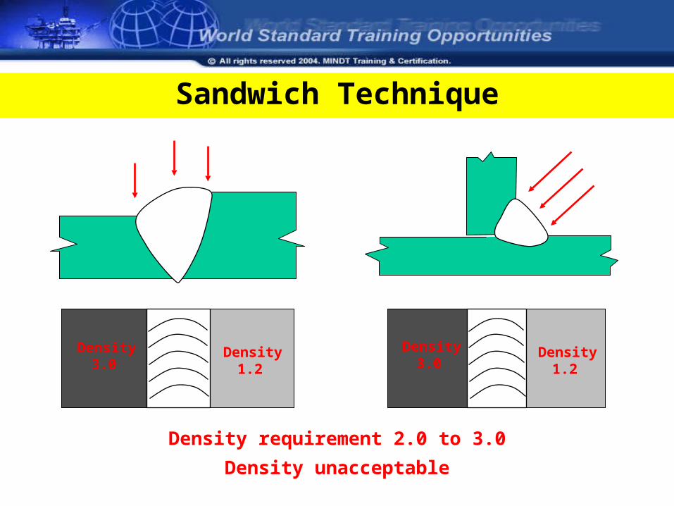
Density requirement 2.0 to 3.0
Density unacceptable
Density1.2
Density1.2
Density3.0
Density3.0
Sandwich Technique
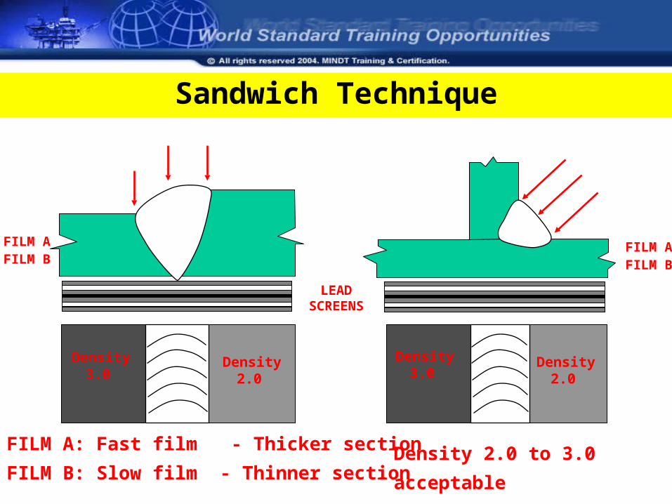
FILM AFILM B
FILM A: Fast film - Thicker section
FILM B: Slow film - Thinner section
LEAD SCREENS
FILM AFILM B
Density2.0
Density2.0
Density3.0
Density3.0
Sandwich Technique
Density 2.0 to 3.0 acceptable
Viewing conditionsViewing conditions
• Darkened room
• Clean viewer
• Minimum adequate illumination from the viewer is 3000cd/m2
• Eyesight must be adjusted to the darkened conditions
• Comfortable viewing position and environment
• Avoid fatigue
Radiographic QualityRadiographic Quality
Density - relates to the degree of darkness
Contrast - relates to the degree of difference in density between adjacent areas on a radiograph
Definition - relates to the degree of sharpness
Sensitivity - relates to the overall quality of the radiograph
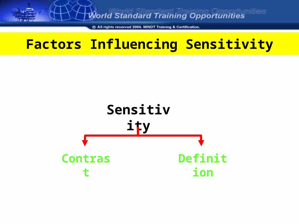
Factors Influencing Sensitivity
Sensitivity
Contrast Definition
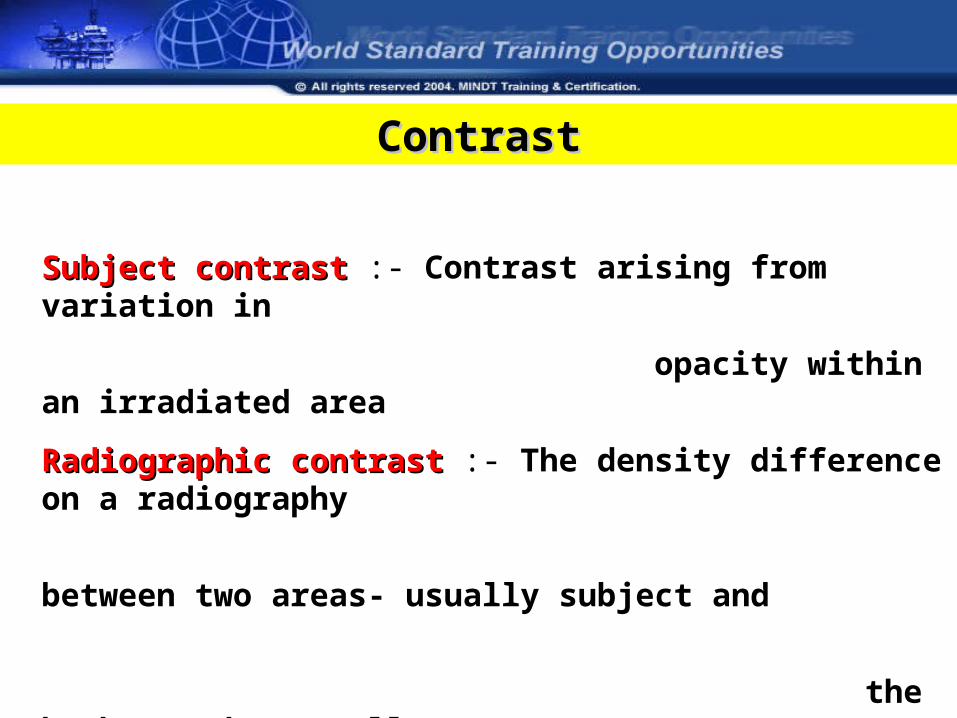
ContrastContrast
Subject contrastSubject contrast :- Contrast arising from variation in
opacity within an irradiated area
Radiographic contrastRadiographic contrast :- The density difference on a radiography
between two areas- usually subject and
the background (overall)
Film contrastFilm contrast :- The slope of characteristic curve of the film at
specified density. ( Type of film being used, fine
grain or large grain)
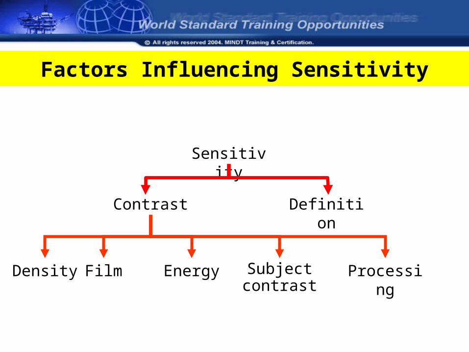
Factors Influencing Sensitivity
Density
Sensitivity
Contrast Definition
Film Energy Subject contrast
Processing
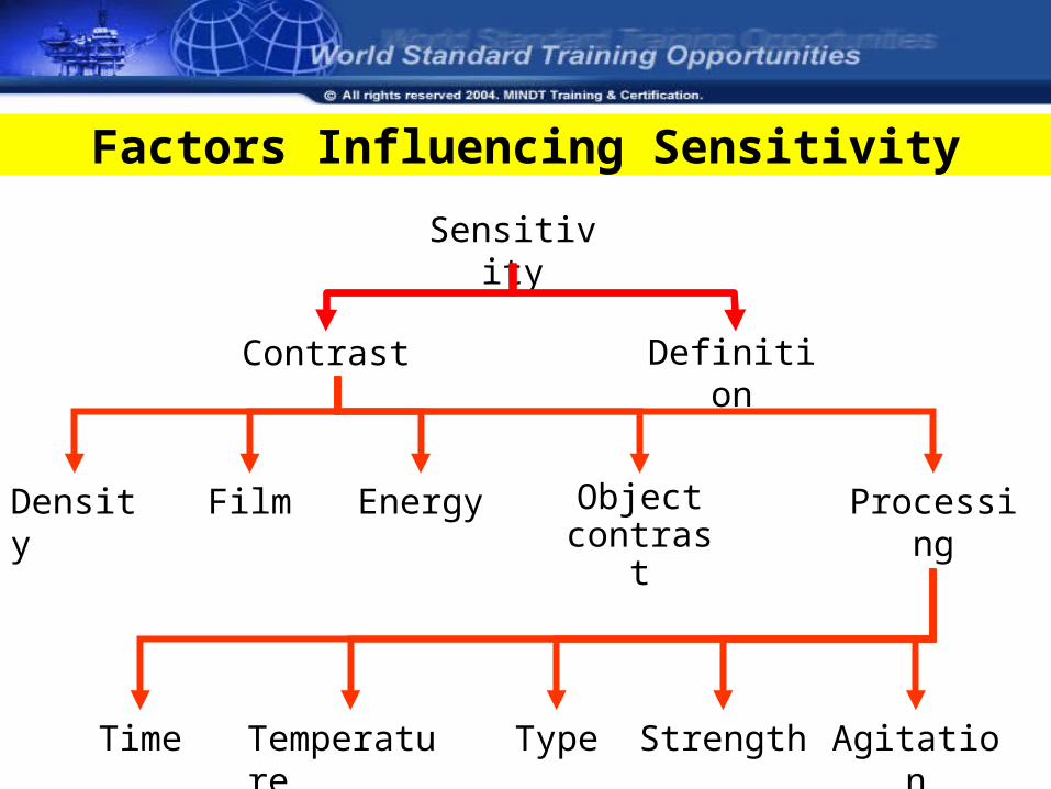
Factors Influencing Sensitivity
Sensitivity
Definition
Density Film Energy Object contrast
Processing
Time Temperature Type Strength Agitation
Contrast
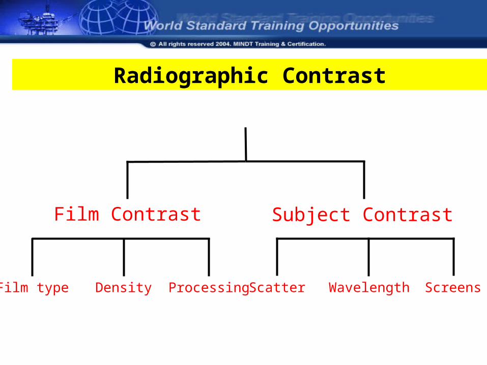
Film Contrast Subject Contrast
Film type Density Processing Scatter Wavelength Screens
Radiographic Contrast
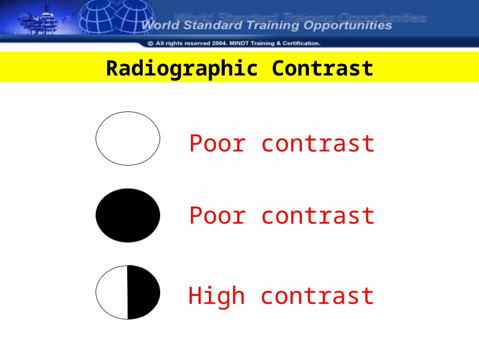
Radiographic Contrast
Poor contrast
Poor contrast
High contrast
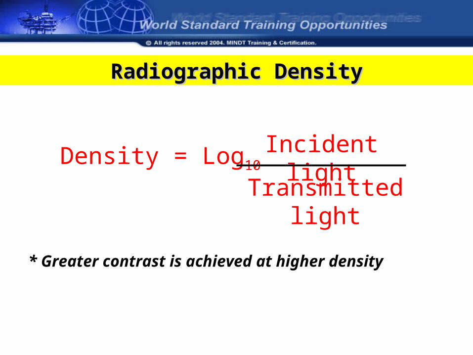
Radiographic DensityRadiographic Density
Density = Log10Incident light
Transmitted light
* Greater contrast is achieved at higher density
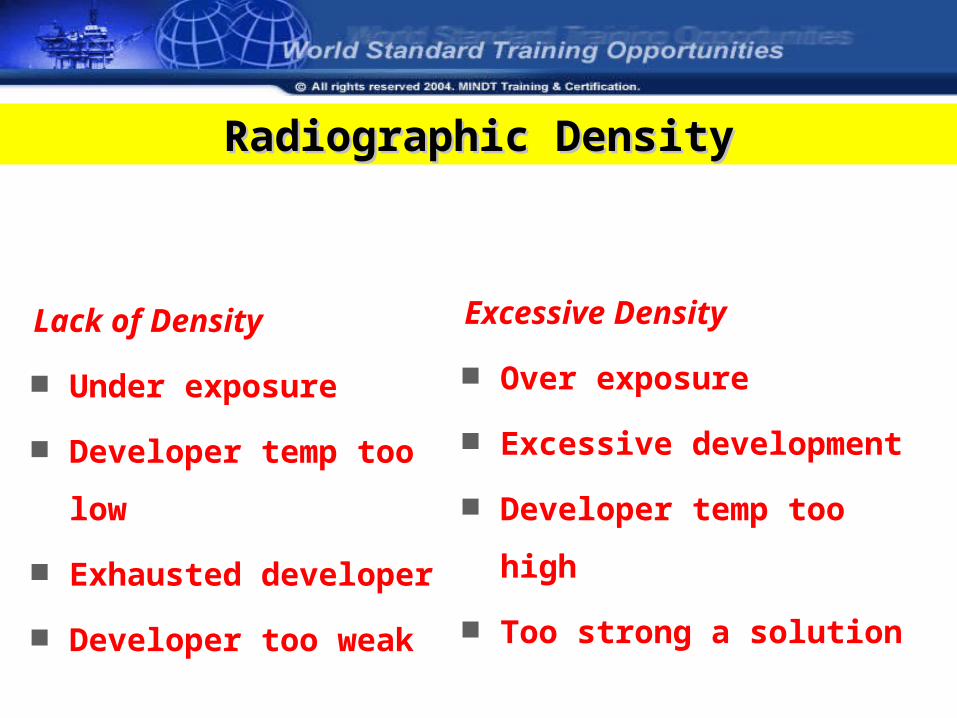
Radiographic DensityRadiographic Density
Lack of Density
Under exposure
Developer temp too low
Exhausted developer
Developer too weak
Excessive Density
Over exposure
Excessive development
Developer temp too high
Too strong a solution
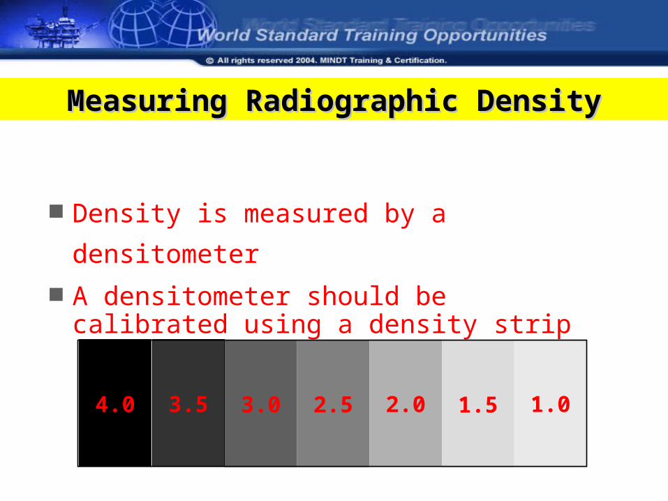
Measuring Radiographic DensityMeasuring Radiographic Density
Density is measured by a densitometer
A densitometer should be calibrated using a density strip
4.0 3.5 3.0 2.5 2.0 1.5 1.0
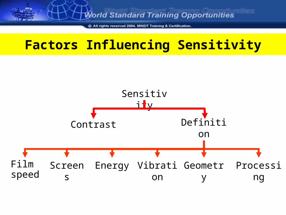
Factors Influencing Sensitivity
Sensitivity
Definition
Film speed
Screens Energy Vibration ProcessingGeometry
Contrast
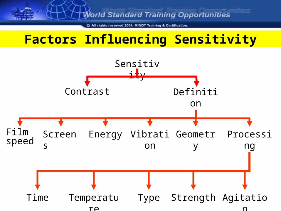
Factors Influencing Sensitivity
Sensitivity
Contrast Definition
Film speed
Screens Energy Vibration Processing
Time Temperature Type Strength Agitation
Geometry
What is a good radiograph?
A good radiograph satisfies A good radiograph satisfies the inspection requirementthe inspection requirement


![Sierra Nevada[1].Power Point.Ppt2.Ppt2.Ppt.2.Ppt.2.Ppt](https://img.pdfslide.net/doc/110x75/55a35a5b1a28ab247d8b464e/sierra-nevada1power-pointppt2ppt2ppt2ppt2ppt.jpg)