Embed Size (px)
Citation preview
Ricardo Powertrain Award 2004 Formula SAE Competition Auburn University #5 Charles Ping
Auburn’s 2004 Formula SAE entry is designed to be predictable and consistent,
with the assumption that driver confidence is a large factor in vehicle performance at the FSAE competition. The powertrain design is an extension of this philosophy. Ample torque and horsepower throughout the RPM range help achieve this goal, while the powertrain design must still meet the proper criteria for vehicle design, rules eligibility, and reliability.
Powerplant Selection
Early in the design process, it was decided that a ~600cc 4-cylinder motorcycle
engine would be utilized. This powerplant is best suited to a fully stressed engine frame design. It also is near the 610cc displacement limit, offering more torque in the unrestricted RPM range. Four cylinders provide a more laminar flow through the restrictor, allowing a smaller plenum and better throttle response compared to 2 or 1 cylinder powerplant designs.
Motorcycle engines in the 600cc range are diverse, offering a range that varies in mass, external dimensions, stock power output, and center of gravity locations. Primary criteria for engine selection were mounting locations (for frame rigidity), overall engine mass, and engine center of gravity location. It is assumed that overall engine output will be similar enough across the 600cc range that stock engine output is not a large consideration. Parts and engine availability are also important, and the engine selected must be attainable given the team’s limited resources.
From this analysis 5 engines were selected for closer comparison. o 1999-2003 Yamaha R6 o 2001-2003 Suzuki GSX-R600 o 1999-2000 Honda F4 o 2001-2003 Honda F4i o 2003-up Honda RR
Scaled engine drawings allowed a close approximation of engine CG, at least
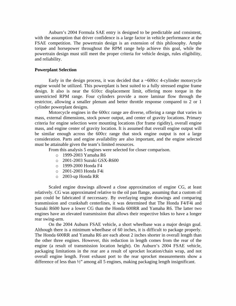
relatively. CG was approximated relative to the oil pan flange, assuming that a custom oil pan could be fabricated if neccessary. By overlaying engine drawings and comparing transmission and crankshaft centerlines, it was determined that The Honda F4/F4i and Suzuki R600 have a lower CG than the Honda 600RR and Yamaha R6. The latter two engines have an elevated transmission that allows their respective bikes to have a longer rear swing-arm.
On the 2004 Auburn FSAE vehicle, a short wheelbase was a major design goal. Although there is a minimum wheelbase of 60 inches, it is difficult to package properly. The Honda 600RR and Yamaha R6 are each about 2 inches shorter in overall length than the other three engines. However, this reduction in length comes from the rear of the engine (a result of transmission location height). On Auburn’s 2004 FSAE vehicle, packaging limitations in the rear are a result of sprocket location/chain wrap, and not overall engine length. Front exhaust port to the rear sprocket measurements show a difference of less than ½” among all 5 engines, making packaging length insignificant.
Honda CBR600F4i, left, compared to elevated transmission design of CBR600RR, right
The engine selection was narrowed down to the Honda F4/F4i and Suzuki R600 due to mounting constraints and CG location. The R600 is the heaviest of the 3, while the F4i offers an integrated camshaft sensor. The Honda F4i is simply a derivative of the F4 engine, with more robust clutch, alternator, and other minor changes. By mounting a F4i cylinder head on a Honda F4 short block and exchanging other internal components, the result is an engine with the functionality of the CBR600F4i and weighing only 1 lb more than the F4. This engine has a low CG, and multiple mounts for the frame. Mechanical Modifications
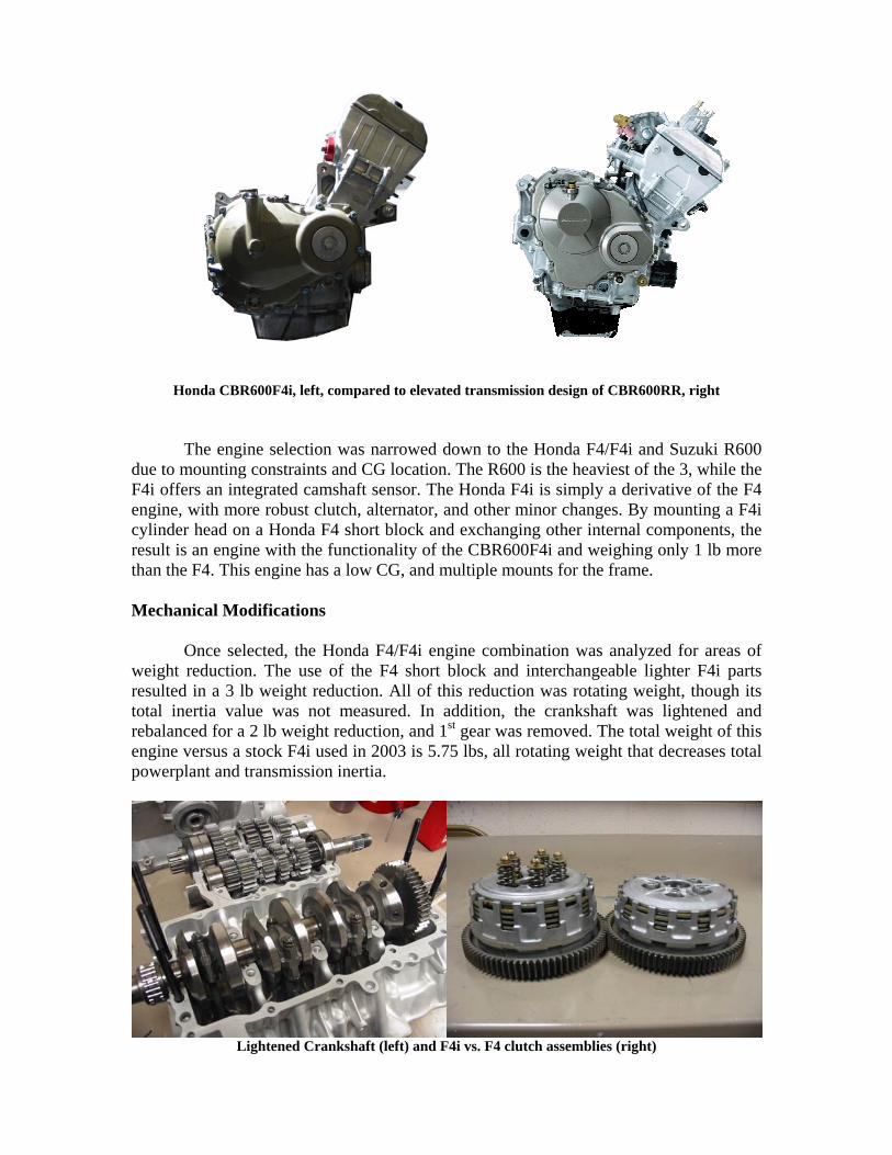
Once selected, the Honda F4/F4i engine combination was analyzed for areas of
weight reduction. The use of the F4 short block and interchangeable lighter F4i parts resulted in a 3 lb weight reduction. All of this reduction was rotating weight, though its total inertia value was not measured. In addition, the crankshaft was lightened and rebalanced for a 2 lb weight reduction, and 1st gear was removed. The total weight of this engine versus a stock F4i used in 2003 is 5.75 lbs, all rotating weight that decreases total powerplant and transmission inertia.
Lightened Crankshaft (left) and F4i vs. F4 clutch assemblies (right)
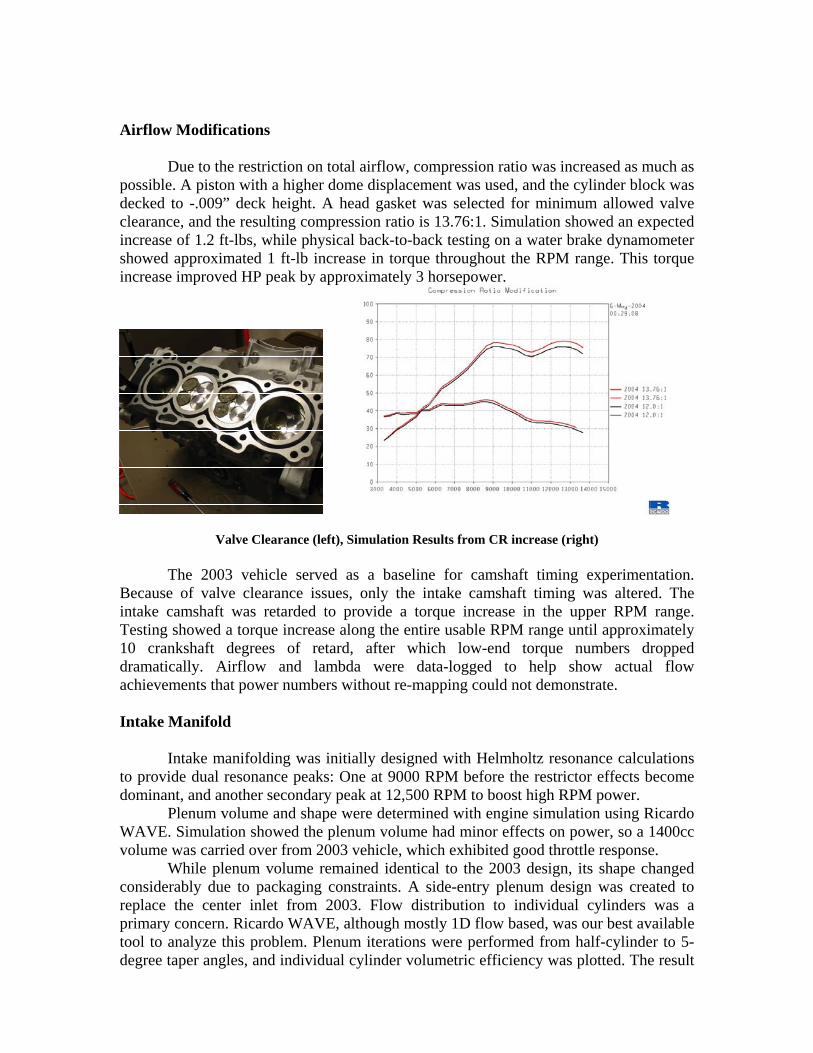
Airflow Modifications Due to the restriction on total airflow, compression ratio was increased as much as
possible. A piston with a higher dome displacement was used, and the cylinder block was decked to -.009” deck height. A head gasket was selected for minimum allowed valve clearance, and the resulting compression ratio is 13.76:1. Simulation showed an expected increase of 1.2 ft-lbs, while physical back-to-back testing on a water brake dynamometer showed approximated 1 ft-lb increase in torque throughout the RPM range. This torque increase improved HP peak by approximately 3 horsepower.
Valve Clearance (left), Simulation Results from CR increase (right) The 2003 vehicle served as a baseline for camshaft timing experimentation.
Because of valve clearance issues, only the intake camshaft timing was altered. The intake camshaft was retarded to provide a torque increase in the upper RPM range. Testing showed a torque increase along the entire usable RPM range until approximately 10 crankshaft degrees of retard, after which low-end torque numbers dropped dramatically. Airflow and lambda were data-logged to help show actual flow achievements that power numbers without re-mapping could not demonstrate. Intake Manifold
Intake manifolding was initially designed with Helmholtz resonance calculations
to provide dual resonance peaks: One at 9000 RPM before the restrictor effects become dominant, and another secondary peak at 12,500 RPM to boost high RPM power.
Plenum volume and shape were determined with engine simulation using Ricardo WAVE. Simulation showed the plenum volume had minor effects on power, so a 1400cc volume was carried over from 2003 vehicle, which exhibited good throttle response.
While plenum volume remained identical to the 2003 design, its shape changed considerably due to packaging constraints. A side-entry plenum design was created to replace the center inlet from 2003. Flow distribution to individual cylinders was a primary concern. Ricardo WAVE, although mostly 1D flow based, was our best available tool to analyze this problem. Plenum iterations were performed from half-cylinder to 5-degree taper angles, and individual cylinder volumetric efficiency was plotted. The result
is a half-cylinder non-tapered design that shows the best flow balance characteristics in the 8000-13000 RPM range.
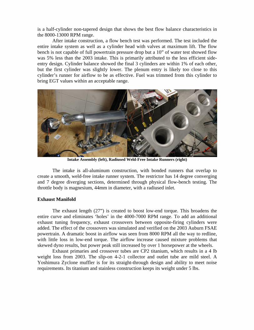
After intake construction, a flow bench test was performed. The test included the entire intake system as well as a cylinder head with valves at maximum lift. The flow bench is not capable of full powertrain pressure drop but a 10” of water test showed flow was 5% less than the 2003 intake. This is primarily attributed to the less efficient side-entry design. Cylinder balance showed the final 3 cylinders are within 1% of each other, but the first cylinder was slightly lower. The plenum entry is likely too close to this cylinder’s runner for airflow to be as effective. Fuel was trimmed from this cylinder to bring EGT values within an acceptable range.
Intake Assembly (left), Radiused Weld-Free Intake Runners (right)
The intake is all-aluminum construction, with bonded runners that overlap to
create a smooth, weld-free intake runner system. The restrictor has 14 degree converging and 7 degree diverging sections, determined through physical flow-bench testing. The throttle body is magnesium, 44mm in diameter, with a radiused inlet. Exhaust Manifold
The exhaust length (27”) is created to boost low-end torque. This broadens the
entire curve and eliminates ‘holes’ in the 4000-7000 RPM range. To add an additional exhaust tuning frequency, exhaust crossovers between opposite-firing cylinders were added. The effect of the crossovers was simulated and verified on the 2003 Auburn FSAE powertrain. A dramatic boost in airflow was seen from 8000 RPM all the way to redline, with little loss in low-end torque. The airflow increase caused mixture problems that skewed dyno results, but power peak still increased by over 1 horsepower at the wheels.
Exhaust primaries and crossover tubes are CP2 titanium, which results in a 4 lb weight loss from 2003. The slip-on 4-2-1 collector and outlet tube are mild steel. A Yoshimura Zyclone muffler is for its straight-through design and ability to meet noise requirements. Its titanium and stainless construction keeps its weight under 5 lbs.
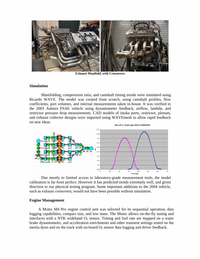
Exhaust Manifold, with Crossovers
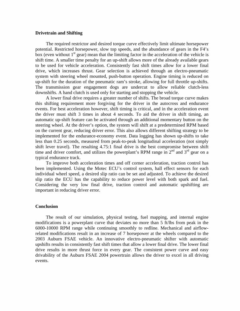
Simulation Manifolding, compression ratio, and camshaft timing trends were simulated using Ricardo WAVE. The model was created from scratch, using camshaft profiles, flow coefficients, port volumes, and internal measurements taken in-house. It was verified to the 2003 Auburn FSAE vehicle using dynamometer feedback, airflow, lambda, and restrictor pressure drop measurements. CAD models of intake ports, restrictor, plenum, and exhaust collector designs were imported using WAVEmesh to allow rapid feedback on new ideas.
Due mostly to limited access to laboratory-grade measurement tools, the model calibration is far from perfect. However it has predicted trends extremely well, and given direction to our physical testing program. Some important additions to the 2004 vehicle, such as exhaust crossovers, would not have been possible without simulation. Engine Management
A Motec M4 Pro engine control unit was selected for its sequential operation, data
logging capabilities, compact size, and low mass. The Motec allows on-the-fly tuning and interfaces with a NTK wideband O2 sensor. Timing and fuel rate are mapped on a water brake dynamometer, and acceleration enrichments and other transient settings tested on the inertia dyno and on the track with on-board O2 sensor data logging and driver feedback.
Drivetrain and Shifting
The required restrictor and desired torque curve effectively limit ultimate horsepower
potential. Restricted horsepower, slow top speeds, and the abundance of gears in the F4’s box (even without 1st gear) mean that the limiting factor in the acceleration of the vehicle is shift time. A smaller time penalty for an up-shift allows more of the already available gears to be used for vehicle acceleration. Consistently fast shift times allow for a lower final drive, which increases thrust. Gear selection is achieved through an electro-pneumatic system with steering wheel mounted, push-button operation. Engine timing is reduced on up-shift for the duration of the pneumatic ram’s stroke, allowing for full throttle up-shifts. The transmission gear engagement dogs are undercut to allow reliable clutch-less downshifts. A hand clutch is used only for starting and stopping the vehicle.
A lower final drive requires a greater number of shifts. The broad torque curve makes this shifting requirement more forgiving for the driver in the autocross and endurance events. For best acceleration however, shift timing is critical, and in the acceleration event the driver must shift 3 times in about 4 seconds. To aid the driver in shift timing, an automatic up-shift feature can be activated through an additional momentary button on the steering wheel. At the driver’s option, the system will shift at a predetermined RPM based on the current gear, reducing driver error. This also allows different shifting strategy to be implemented for the endurance-economy event. Data logging has shown up-shifts to take less than 0.25 seconds, measured from peak-to-peak longitudinal acceleration (not simply shift lever travel). The resulting 4.75:1 final drive is the best compromise between shift time and driver comfort, and utilizes the powerplant’s RPM range in 2nd and 3rd gear on a typical endurance track.
To improve both acceleration times and off corner acceleration, traction control has been implemented. Using the Motec ECU’s control system, hall effect sensors for each individual wheel speed, a desired slip ratio can be set and adjusted. To achieve the desired slip ratio the ECU has the capability to reduce power level with both spark and fuel. Considering the very low final drive, traction control and automatic upshifting are important in reducing driver error.
Conclusion
The result of our simulation, physical testing, fuel mapping, and internal engine modifications is a powerplant curve that deviates no more than 5 ft/lbs from peak in the 6000-10000 RPM range while continuing smoothly to redline. Mechanical and airflow-related modifications result in an increase of 7 horsepower at the wheels compared to the 2003 Auburn FSAE vehicle. An innovative electro-pneumatic shifter with automatic upshifts results in consistently fast shift times that allow a lower final drive. The lower final drive results in more thrust force in every gear. The consistent power curve and easy drivability of the Auburn FSAE 2004 powertrain allows the driver to excel in all driving events.
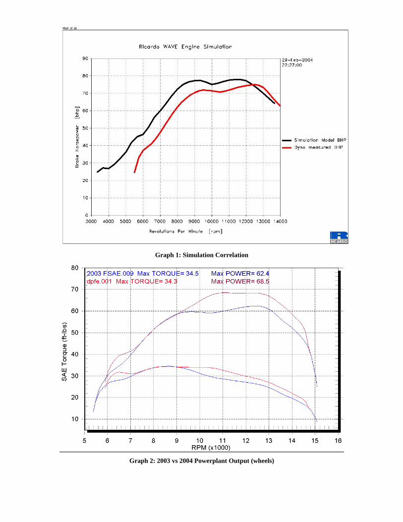
Graph 1: Simulation Correlation
Graph 2: 2003 vs 2004 Powerplant Output (wheels)
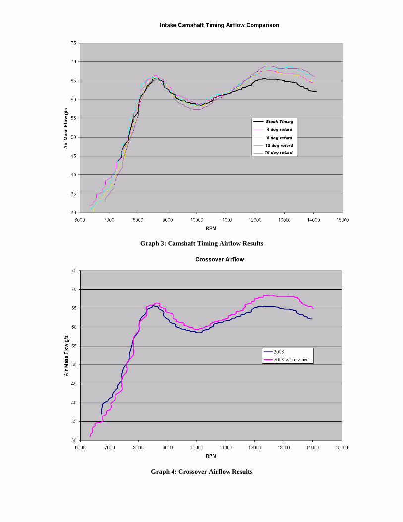
Graph 3: Camshaft Timing Airflow Results
Graph 4: Crossover Airflow Results
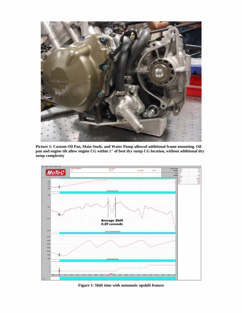
Picture 1: Custom Oil Pan, Main Studs, and Water Pump allowed additional frame mounting. Oil pan and engine tilt allow engine CG within 1" of best dry sump CG location, without additional dry sump complexity
Figure 1: Shift time with automatic upshift feature