Embed Size (px)
Citation preview
Update June 2009:
The following is some updated information regarding
http://www.mtaonline.net/~hheffner/HullMotor.pdf
fig. 3 provided below is an improved version of Fig. 3 in the above original work. Fig. 4 is not yet available.
An alternative explanation emerged on the web: thermal expansion of the bearings:
http://www.electricstuff.co.uk/bbmotor.html
Videos of related interest:
http://www.youtube.com/watch?v=g60okBMeTKo&NR=1
http://www.youtube.com/watch?v=-1PgR1hyXHs&feature=related
http://www.youtube.com/watch?v=OJK-W9FwjMc
It still seems more reasonable the cause is electromagnetic, and specifically hysteresis related.
One obvious conclusion from the hypothesis that the torque of the ball bearing motor is primarily due to hysteresis in the races, and thus is proportional to i^2, is that the most efficient motor will, all other things being equal, have a shaft with the least possible resistance. This implies the following conclusions regarding the shaft:
1. copper is better than iron or steel 2. silver is even better 3. shorter is better 4. a solid bar is better than a pipe 5. good electrical contact between the shaft and the inner race is important
Something that would provide many people the chance to first hand experiment would be to locate a cheap source for nonmagnetic stainless steel bearings. Nonmagnetic (relative permeability 1.01 or less) bearings exist:
Richard Hull’s Mysterious Motor
Horace Heffner June 2009
Page 1

http://www.nsk.com/products/spacea/nonmagnetic/
but look pricey.
Here is a Thomas register list of suppliers of nonmagnetic bearings:
http://www.thomasnet.com/products/bearings-ball-nonmagnetic-3920402-1.html
http://tinyurl.com/lbe8ck
Here are some alternatives in the under $30 range:
http://www.thomasnet.com/catalognavigator.html?cov=NA&what=nonmagnetic+ball+bearings&heading=3920402&cid=270891&CNID=&cnurl=http%3A%2F%2Fkmsbearings.thomasnet.com%2FCategory%2Fradial-ball-bearings-3
http://tinyurl.com/mk3o4d
Other types available in the same metals:
http://www.thomasnet.com/catalognavigator.html?cov=NA&what=nonmagnetic+ball+bearings&heading=3920402&cid=270891&CNID=&cnurl=http%3A%2F%2Fkmsbearings.thomasnet.com%2FCategory%2Fradial-ball-bearings-3
http://tinyurl.com/mk3o4d
It would be ideal to locate really cheap nonmagnetic bearings that have identically sized and cheap magnetic counterparts.
Using nonmagnetic bearings as a control will only establish that magnetic materials are required (or not).
The fact the effect is due entirely to hysteresis limits the effective rpm range across which the motor responds with a force (torque) proportional to i^2. There has to be a balance of current to load to optimize the motor efficiency. For a DC test, an appropriate test of principle would simultaneously increase the load in order to sustain a constant rpm, and thus maintain the magnetization timing. An inherent assumption in the "torque proportional to i^2" assertion, is that the motor is operating in an efficient range, and as well not saturating.
Richard Hull’s Mysterious Motor
Horace Heffner June 2009
Page 2
A sufficient time is required to overcome the magnetization hysteresis in order to have a sufficient M to produce the i L x B torque. Similarly, the M field must last long enough in the material without the supporting H that it rotates into position such that the current i passes through it. The combined effect is a kind of wave of magnetization to both sides of the contact points. Optimization places the current right in or near the appropriate peak of that wave.
If pulsed DC is used, and the pulse of current is too fast, and the time between pulses too long, then the initial magnetization will occur, and possibly even saturate the material, but by the time the magnetized material rotates into the contact point location, there is no current with which to generate the i L x B force, thus the motor will have no torque at all.
Under the thermal scenario, the heat (energy) applied is an i^2 R effect, where R is the resistance. However, to maintain a constant torque for a given current, the same degree of expansion has to be maintained at every revolution. Therefore the power requirements must increase with angular velocity. The energy to support, via thermal expansion, the extreme speeds at which some of the motors now operate should take an extreme amount of power. As the designs improve magnetically, you can see the power required drops, the current required drops, and the zero load peak angular velocity and the initial acceleration both increase dramatically.
In any case, a Marinov ball bearing motor made entirely of nonmagnetic material will quickly resolve the thermal vs magnetic explanations. A complex FEA dynamic model would be required to optimize the design, or to verify the theory quantitatively, i.e. to perfectly match theory to performance.
Experiment Construction
Some nonmagnetic stainless bearings were obtained from KMS Bearings:
http://www.thomasnet.com/catalognavigator.html?cov=NA&what=nonmagnetic+ball+bearings&heading=3920402&cid=270891&CNID=&cnurl=http%3A%2F%2Fkmsbearings.thomasnet.com%2FCategory%2Fradial-ball-bearings-3
http://tinyurl.com/mk3o4d
Two SSR8A-6-1/2B bearings with 1/2” ID, 1 1/8” OD, 3/8” width were ordered. They
Richard Hull’s Mysterious Motor
Horace Heffner June 2009
Page 3
are single row, 316 Stainless Raceways Radial Ball Bearings fitted with SS316 Balls.
Their lubricant washes out with soap and water. I didn't, but probably should have ordered the model with a high temperature cage, but it only has to run (or not run) for a few seconds to test the thermal expansion hypothesis.
In addition, two Z99R8 1/2” ID, 1 1/8” General Bearing Corp. ordinary steel bearings were obtained locally. Fig. 5 is a photo of the four bearings obtained.
The stainless bearings were washed with hot water and Goo-gone soap. Both sets of bearings were then given washes in gasoline, followed by 24 hour washes in mineral spirits, and then acetone. The extra washes were due to initially poor and intermittent conductivity through the bearings.
For use as flywheels, two all (nonmagnetic) zinc 4 inch OD die cast V-belt pulleys, at $6.70 each, were obtained from:
http://www.mcmaster.com
The steel set screws were removed, and plastic electrician’s tape was used to adhere the pulleys to the shafts. The shafts were made of 1/2” solid aluminum bar obtained from Home Depot.
Dimples were made on the shafts in order to limit the range of motion of the pulleys on the shafts, and to increase the firmness of electrical contact.
Fig. 6 shows a side view of the experiment board under construction, including the 12 V motorcycle battery purchased at Wal-Mart.
The Experiments
Fig. 7 shows the experiment board wired with the two motors in series. The nichrome resistor was measured at about 0.3 ohms. Channel 1 of the scope is across the battery, Channel 2 is across the current resistor.
This experiment did not produce continuous rotation of either type motor, due to
Richard Hull’s Mysterious Motor
Horace Heffner June 2009
Page 4
insufficient current. The oscilloscope trace did show good series conduction through all 4 bearings however.
It was decided to next try a single motor at a time, to be sure enough current could be obtained. Single motor mode was achieved by shunting across the bearing mounts on the left and moving the magnetic bearings over to the right side. No luck first try. The resistor was cut in half, to 0.15 ohms roughly. Measured 10 V across the resistor, and a 1.6 reduction in potential across the battery, giving 67 amps for the run, but still no luck getting sustained rotation. The magnetic bearings did show signs of an increased spin down time.
Then the resistor was cut roughly in half again, giving the configuration shown in Fig. 8 below. The resistance was actually measured at 0.0631 ohms cold, the voltage drop across the resistor 9.20 V, and the voltage reduction across the battery was 2.00, down to 10 V. The initial cold current was therefore 145 A. Fig. 9 shows the scope post run. The motor ran, not very fast, but sustained an rpm faster than the initial manually produced speed. Here is a video of this control run.
http://www.youtube.com/watch?v=A2XBPzxXtJk
Note the resistor slowly picking up an orange glow as the run continues, and dropping it when the power is cycled off.
Next, for the live run, stainless bearings were exchanged for the magnetic steel bearings. The voltage drop across the resistor was 8.80 V, the voltage reduction across the battery was 2.4 V, to 9.6 V. The intial cold current was about 139 amps. The scope trace is shown in Fig. 10. It proves that current was flowing uniformly through the stainless bearings. It was 139/145 = 96 percent of that flowing through the magnetic bearings, so is definitely enough to show a positive effect on spin down time, rather than the negative effect observed. Here is the video of the test run:
http://www.youtube.com/watch?v=3cllaQFkxQQ
Notice how quickly applying current puts the breaks on. This is just the opposite of the magnetic bearings, which speed up. The same grinding noise does appear when the current is on. This may be due to arcing.
The nonmagnetic bearings were removed from their shaft. One of them had a rough
Richard Hull’s Mysterious Motor
Horace Heffner June 2009
Page 5
feel to its rotation, confirming that arcing and possible intermittent welding had roughened up either the balls or the races. Powdered graphite lubricant was added and the bearings worked a while to grind up and disburse it, which improved spin-down time, but the bad bearing still made noise. When reassembled and a run made, the grinding noise when power was applied had disappeared. The voltage drop across the 0.0631 ohm resistor was 8.5 volts, giving 135 amps, only a slight current reduction. The voltage reduction across the battery was 2.4 V. The breaking effect and noise from applying current disappeared. There was still no sign of increased spin down time.
Conclusions
It is discouraging that the stainless bearings could not be made as friction free as the magnetic ones, though the difference was not large. Their plastic spacer rings are the likely source of the friction problem. Use of powdered graphite is recommended because it reduces friction, maintains good electrical contact, and avoids the problem of arcing quickly damaging the stainless steel bearings.
Stainless steel notoriously welds very much better than ordinary steel, because the surface doesn't quickly pacify by oxidation like ordinary steel. The art of this experiment is getting things to run without destroying the stainless bearings by welding. This means running at the lowest possible current that gets clear results.
It may have been an improvement to run these tests with even more current, but the battery was about at its limit. However, the videos demonstrate clearly that the nonmagnetic stainless steel bearings slow when current is applied, and the ordinary magnetic steel bearings speed up to a sustained motion. This result eliminates thermal expansion as an explanation for the performance of the Marinov Ball Bearing Motor. Given there is an explanation provided for the observed torque using conventional physics, there is no reason to expect there is anything anomalous about this kind of motor at all, or that it demonstrates any form of Marinov’s longitudinal force. However, work continues and is documented here:
http://www.mtaonline.net/~hheffner/HullMotor2.pdf
Figures follow.
Richard Hull’s Mysterious Motor
Horace Heffner June 2009
Page 6
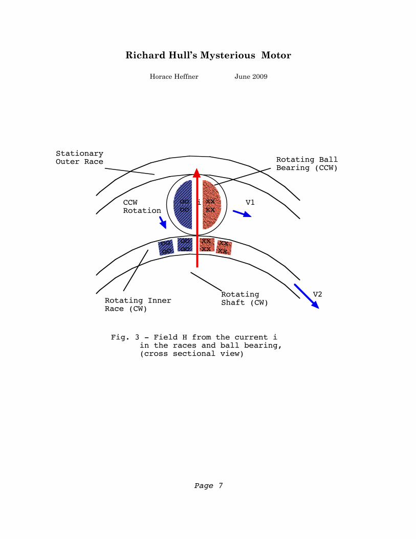
Rotating Ball Bearing (CCW)
Stationary Outer Race
Rotating Inner Race (CW)
i
Rotating Shaft (CW)
CCWRotation
V1
V2
Fig. 3 - Field H from the current i in the races and ball bearing, (cross sectional view)
xxxx
xxxx
oooo
oooo
xxxx
oooo
Richard Hull’s Mysterious Motor
Horace Heffner June 2009
Page 7
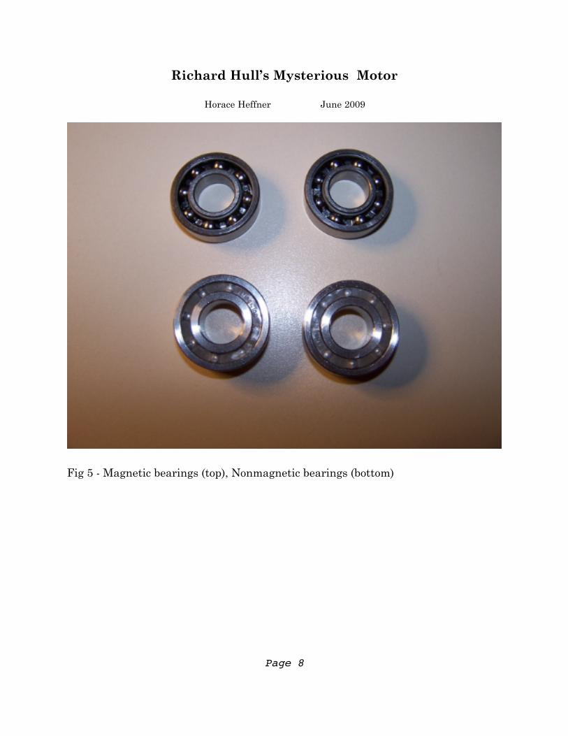
Fig 5 - Magnetic bearings (top), Nonmagnetic bearings (bottom)
Richard Hull’s Mysterious Motor
Horace Heffner June 2009
Page 8
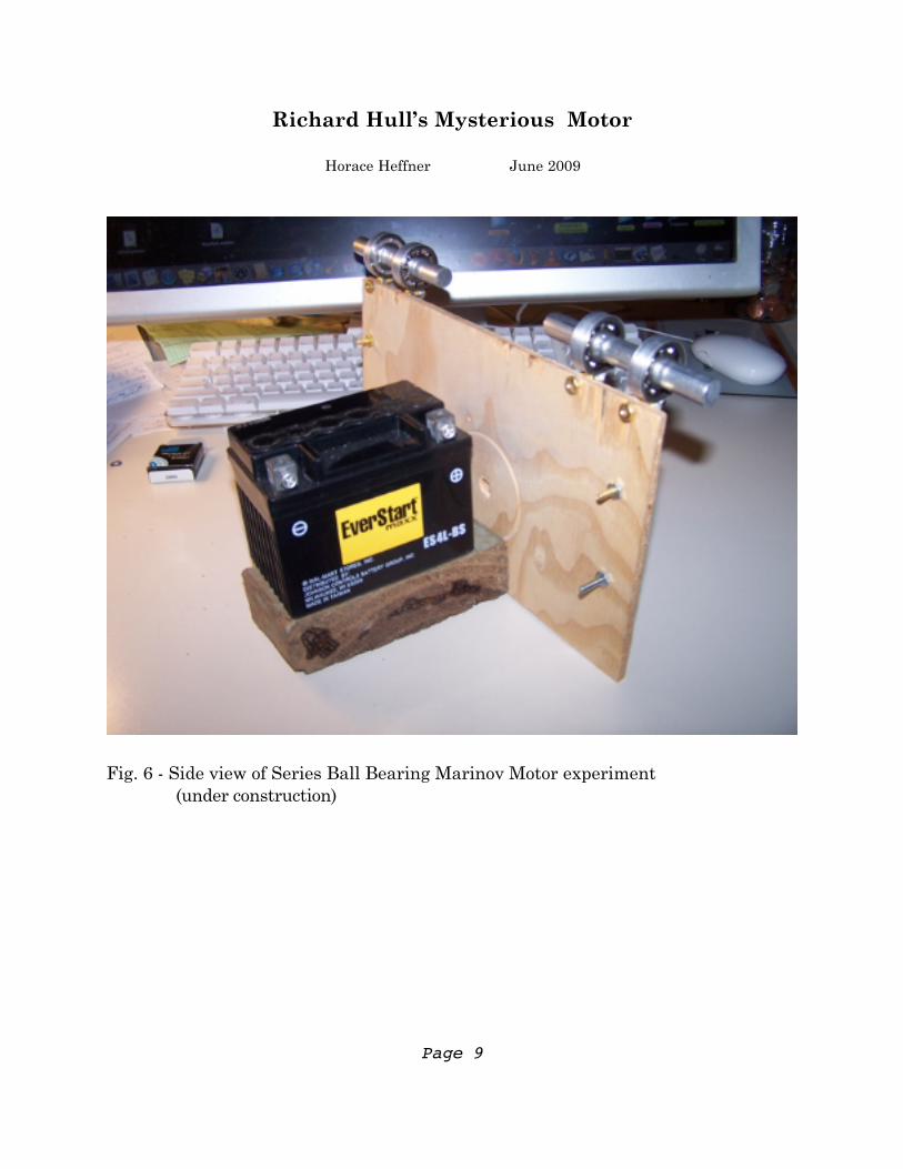
Fig. 6 - Side view of Series Ball Bearing Marinov Motor experiment (under construction)
Richard Hull’s Mysterious Motor
Horace Heffner June 2009
Page 9
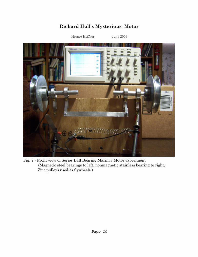
Fig. 7 - Front view of Series Ball Bearing Marinov Motor experiment (Magnetic steel bearings to left, nonmagnetic stainless bearing to right. Zinc pulleys used as flywheels.)
Richard Hull’s Mysterious Motor
Horace Heffner June 2009
Page 10
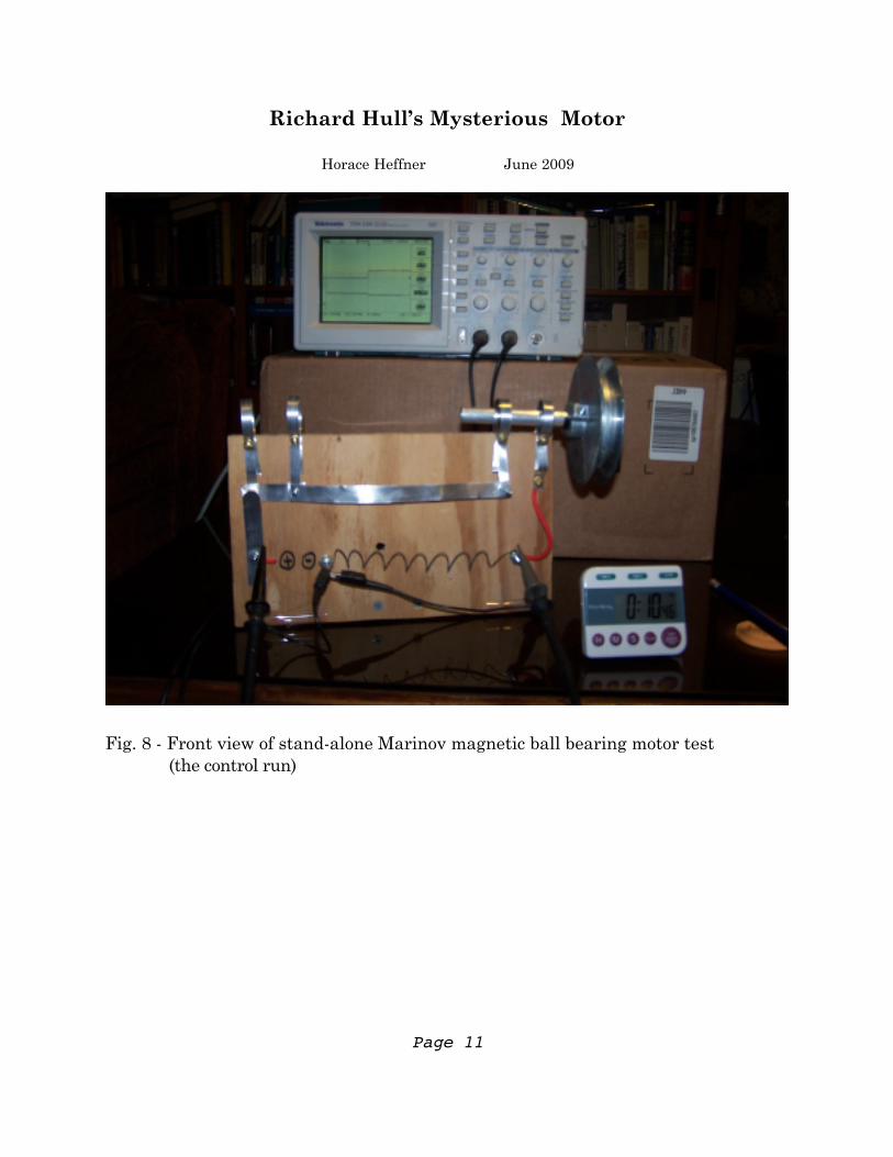
Fig. 8 - Front view of stand-alone Marinov magnetic ball bearing motor test (the control run)
Richard Hull’s Mysterious Motor
Horace Heffner June 2009
Page 11
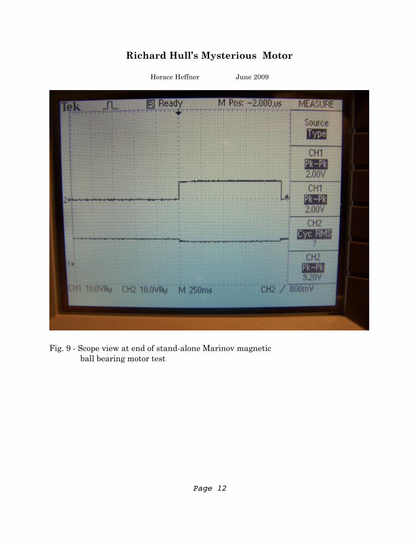
Fig. 9 - Scope view at end of stand-alone Marinov magnetic ball bearing motor test
Richard Hull’s Mysterious Motor
Horace Heffner June 2009
Page 12
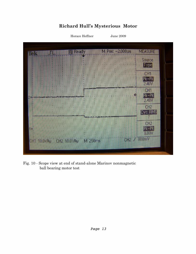
Fig. 10 - Scope view at end of stand-alone Marinov nonmagnetic ball bearing motor test
Richard Hull’s Mysterious Motor
Horace Heffner June 2009
Page 13