Embed Size (px)
Citation preview
Ring artifact removal method using GPU-based FDK reconstruction for cone beam CT Zsolt Adam Balogh
[email protected] R & D Mediso Ltd.
2-3 June 2016 Budapest, Hungary
GPU DAY 2016 - THE FUTURE OF MANY-CORE COMPUTING IN SCIENCE
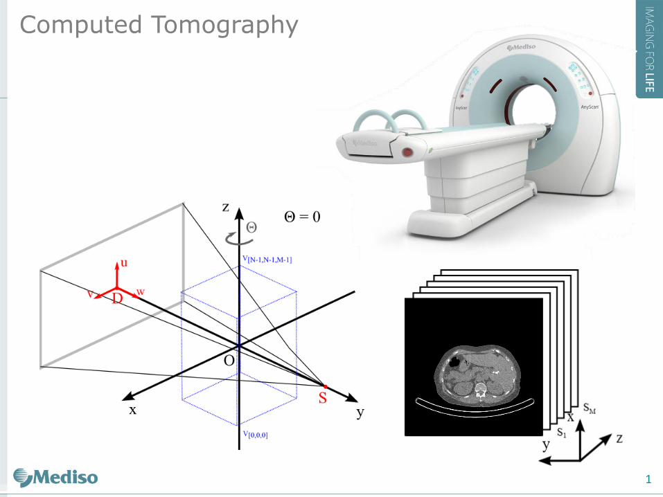
Computed Tomography
1
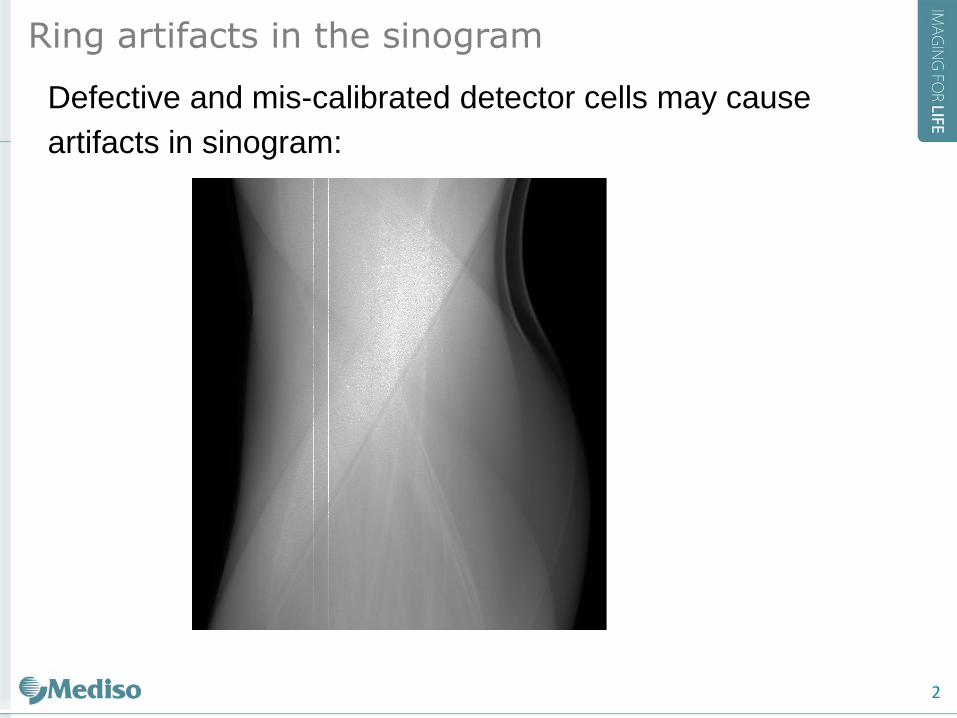
Defective and mis-calibrated detector cells may cause
artifacts in sinogram:
Ring artifacts in the sinogram
2
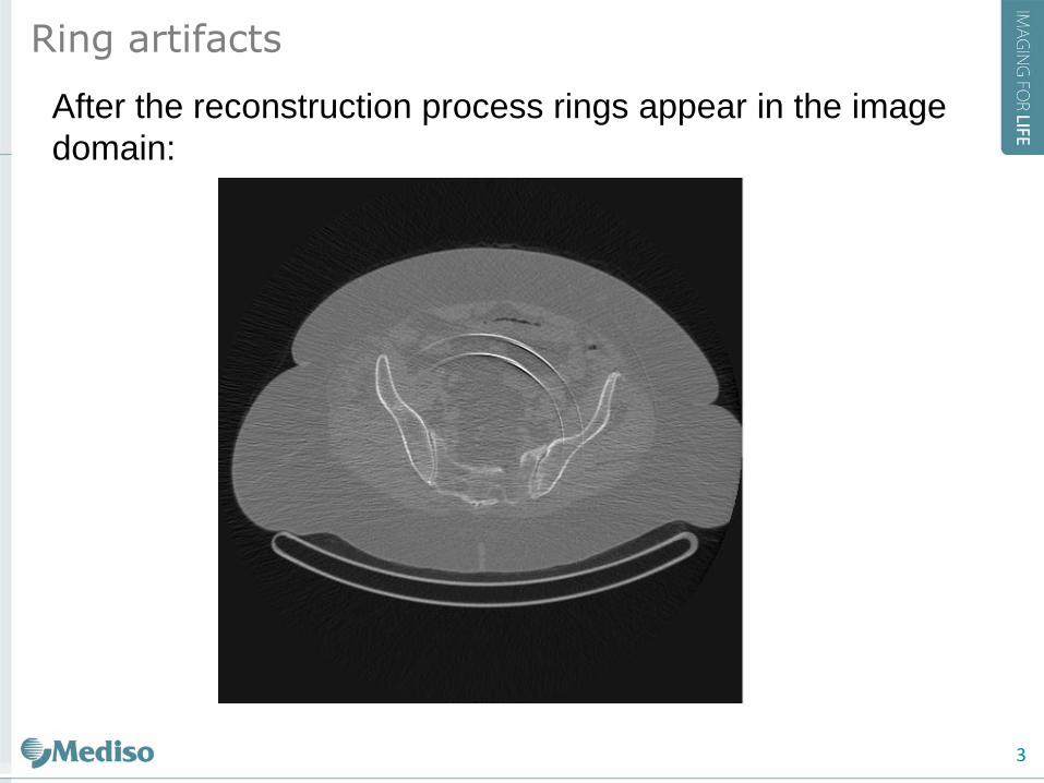
After the reconstruction process rings appear in the image
domain:
Ring artifacts
3
Classification of ring artifact correction methods
• Image-space methods
• Reconstruct image and remove rings in image
space.
• Fourier-space methods
• Apply low pass filter in fourier space (during the
FDK reconstruction process)
• Sinogram-space methods
• Find defective pixels and correct in sinogram space.
Ring artifacts
4
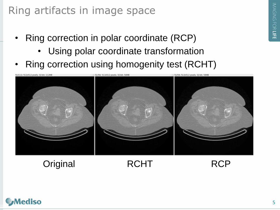
• Ring correction in polar coordinate (RCP)
• Using polar coordinate transformation
• Ring correction using homogenity test (RCHT)
Original RCHT RCP
Ring artifacts in image space
5
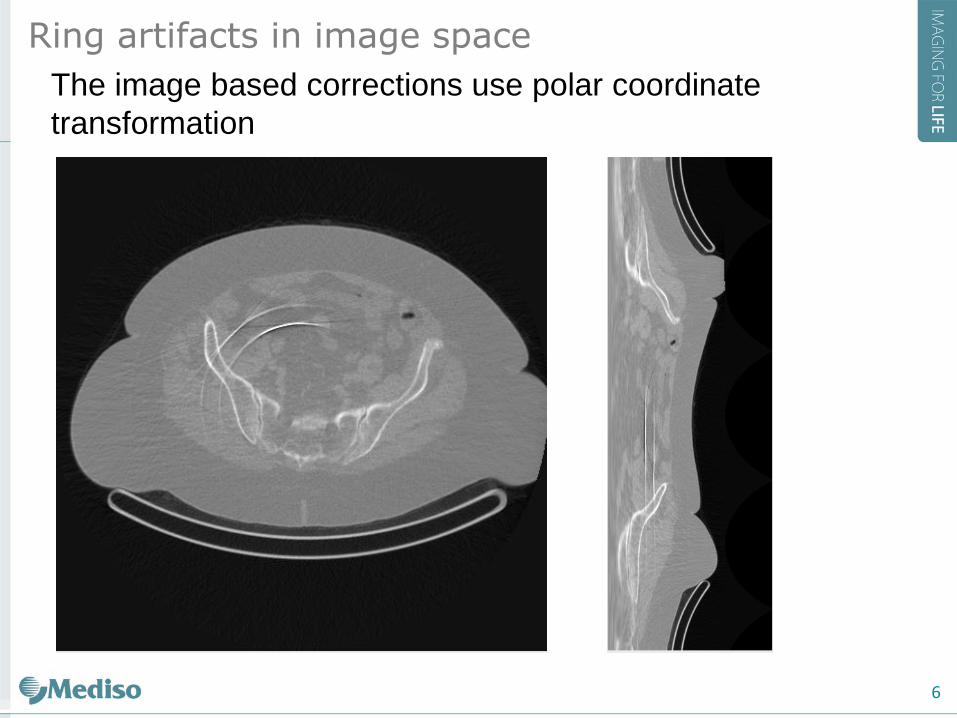
The image based corrections use polar coordinate
transformation
Ring artifacts in image space
6
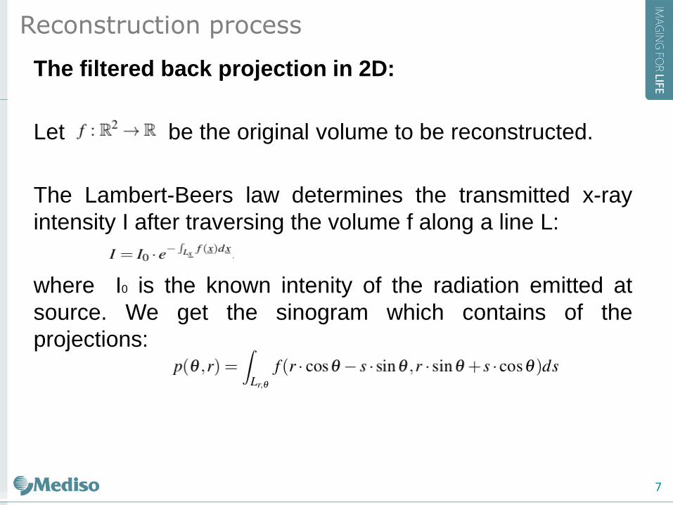
The filtered back projection in 2D:
Let be the original volume to be reconstructed.
The Lambert-Beers law determines the transmitted x-ray
intensity I after traversing the volume f along a line L:
where I0 is the known intenity of the radiation emitted at
source. We get the sinogram which contains of the
projections:
Reconstruction process
7
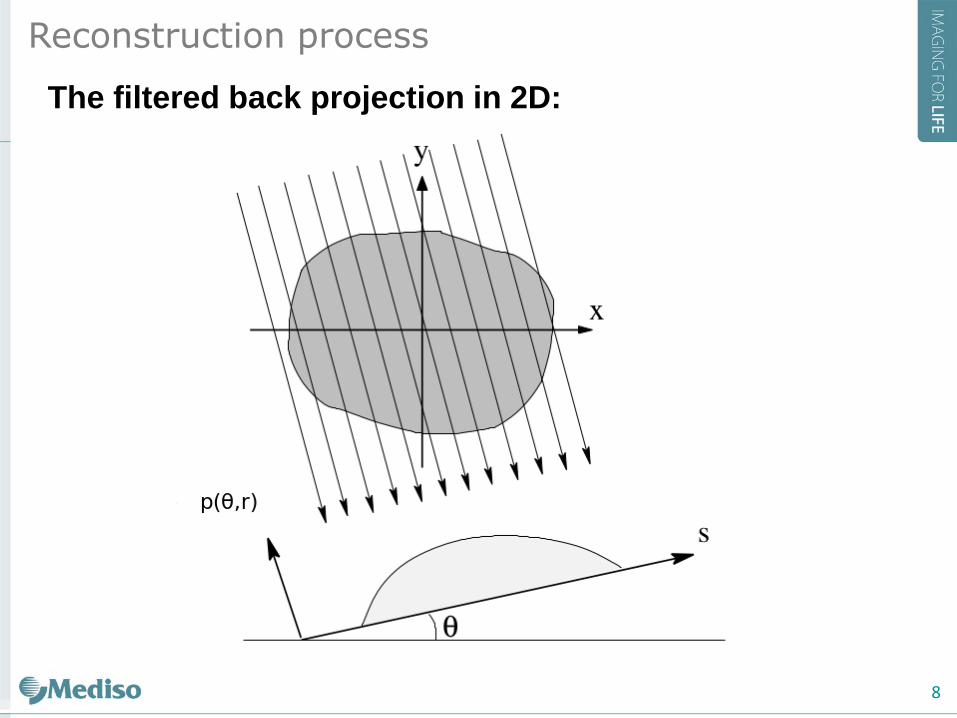
The filtered back projection in 2D:
Reconstruction process
8
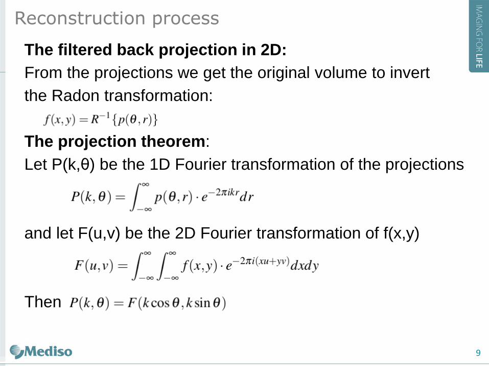
The filtered back projection in 2D:
From the projections we get the original volume to invert
the Radon transformation:
The projection theorem:
Let P(k,θ) be the 1D Fourier transformation of the projections
and let F(u,v) be the 2D Fourier transformation of f(x,y)
Then
Reconstruction process
9
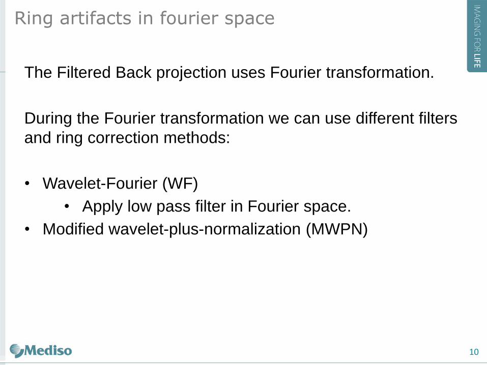
The Filtered Back projection uses Fourier transformation.
During the Fourier transformation we can use different filters
and ring correction methods:
• Wavelet-Fourier (WF)
• Apply low pass filter in Fourier space.
• Modified wavelet-plus-normalization (MWPN)
Ring artifacts in fourier space
10
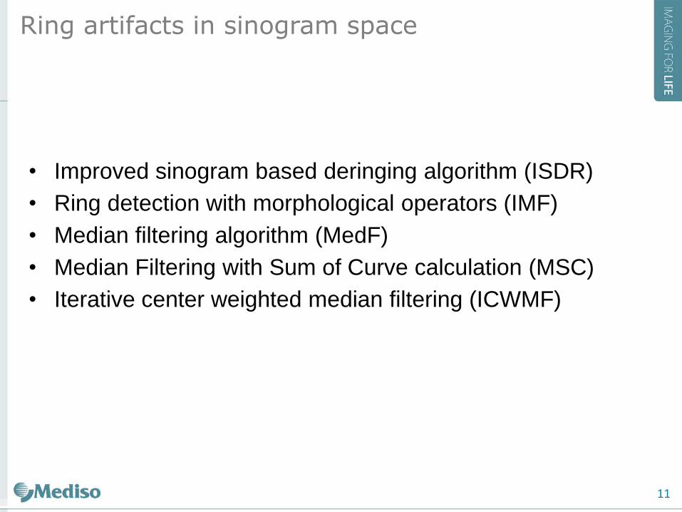
• Improved sinogram based deringing algorithm (ISDR)
• Ring detection with morphological operators (IMF)
• Median filtering algorithm (MedF)
• Median Filtering with Sum of Curve calculation (MSC)
• Iterative center weighted median filtering (ICWMF)
Ring artifacts in sinogram space
11
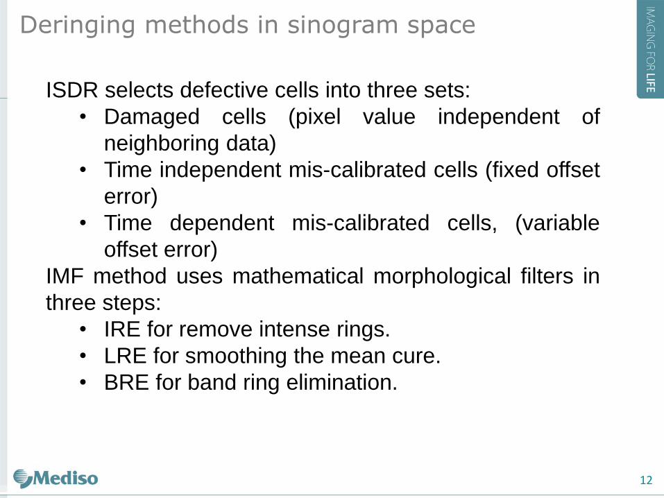
ISDR selects defective cells into three sets:
• Damaged cells (pixel value independent of
neighboring data)
• Time independent mis-calibrated cells (fixed offset
error)
• Time dependent mis-calibrated cells, (variable
offset error)
IMF method uses mathematical morphological filters in
three steps:
• IRE for remove intense rings.
• LRE for smoothing the mean cure.
• BRE for band ring elimination.
Deringing methods in sinogram space
12
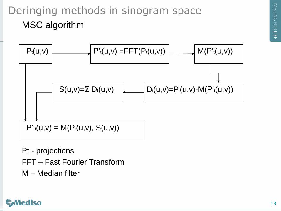
MSC algorithm
Pt - projections
FFT – Fast Fourier Transform
M – Median filter
Deringing methods in sinogram space
Pt(u,v) P’t(u,v) =FFT(Pt(u,v)) M(P’t(u,v))
Dt(u,v)=Pt(u,v)-M(P’t(u,v)) S(u,v)=Σ Dt(u,v)
P’’t(u,v) = M(Pt(u,v), S(u,v))
13
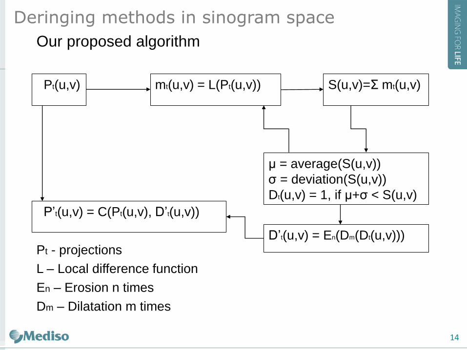
Our proposed algorithm
Pt - projections
L – Local difference function
En – Erosion n times
Dm – Dilatation m times
Deringing methods in sinogram space
Pt(u,v) mt(u,v) = L(Pt(u,v)) S(u,v)=Σ mt(u,v)
μ = average(S(u,v))
σ = deviation(S(u,v))
Dt(u,v) = 1, if μ+σ < S(u,v)
P’t(u,v) = C(Pt(u,v), D’t(u,v))
D’t(u,v) = En(Dm(Dt(u,v)))
14
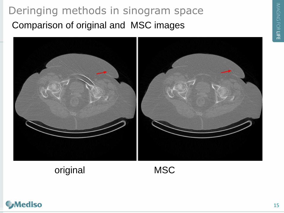
Comparison of original and MSC images
original MSC
Deringing methods in sinogram space
15
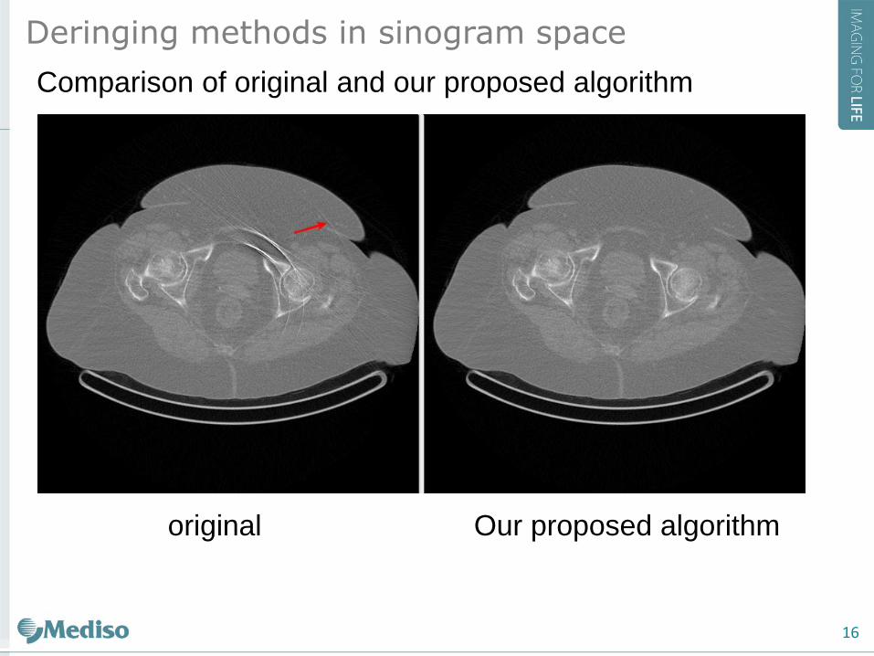
Comparison of original and our proposed algorithm
original Our proposed algorithm
Deringing methods in sinogram space
16
17
Implementation environment
CUDA (Compute Unified Device Architecture)
A parallel computing platform and programming model
invented by NVIDIA. It increases in computing performance
by exploiting the power of the graphics processing unit
(GPU).
Hardware
Kepler microarchitecture
GeForce GTX TITAN Black
compute capacity 3.5,
memory 6 GB,
CUDA cores 2688
18
Implementation environment
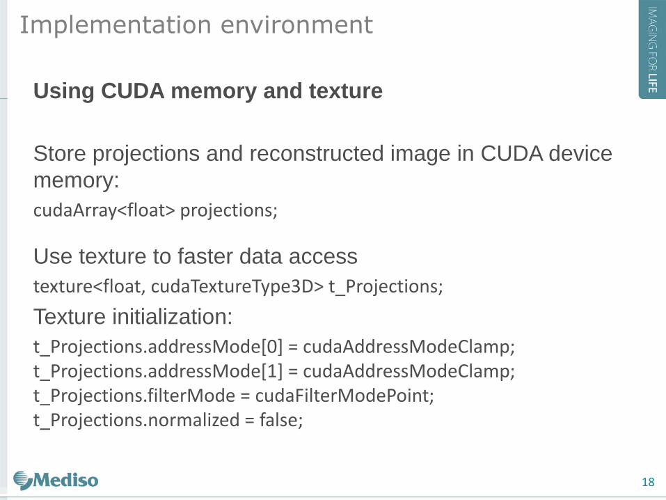
Using CUDA memory and texture
Store projections and reconstructed image in CUDA device
memory:
cudaArray<float> projections;
Use texture to faster data access
texture<float, cudaTextureType3D> t_Projections;
Texture initialization:
t_Projections.addressMode[0] = cudaAddressModeClamp; t_Projections.addressMode[1] = cudaAddressModeClamp; t_Projections.filterMode = cudaFilterModePoint; t_Projections.normalized = false;
19
Implementation environment
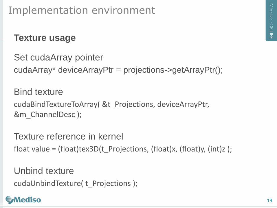
Texture usage
Set cudaArray pointer
cudaArray* deviceArrayPtr = projections->getArrayPtr();
Bind texture
cudaBindTextureToArray( &t_Projections, deviceArrayPtr, &m_ChannelDesc );
Texture reference in kernel
float value = (float)tex3D(t_Projections, (float)x, (float)y, (int)z );
Unbind texture
cudaUnbindTexture( t_Projections );
20
Implementation environment
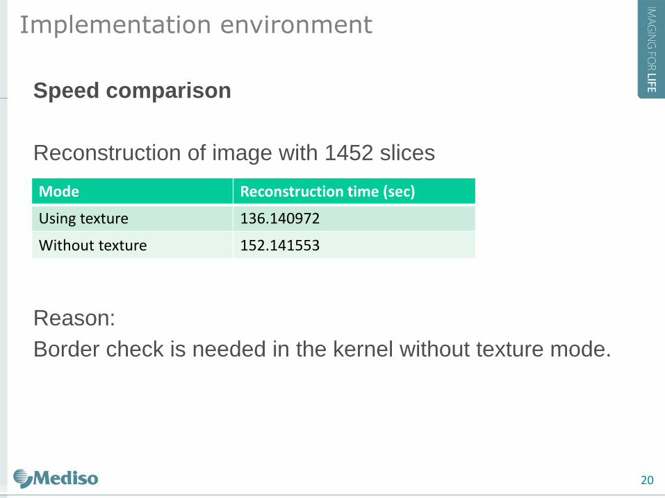
Speed comparison
Reconstruction of image with 1452 slices
Reason:
Border check is needed in the kernel without texture mode.
Mode Reconstruction time (sec)
Using texture 136.140972
Without texture 152.141553

www.mediso.com
Thank you for your attention!
21

![FDK-TypeAlgorithmswithNoBackprojectionWeightfor ...2 International Journal of Biomedical Imaging Davis and Kress (FDK) [13] originally proposed for circular scan CB reconstruction,](https://img.pdfslide.net/doc/110x75/6117d4bb915e6c21290de043/fdk-typealgorithmswithnobackprojectionweightfor-2-international-journal-of-biomedical.jpg)