Embed Size (px)
Citation preview
RISK IMPLICATION OF USING ACCIDENT TOLERANT FUELS IN LWRS
Koroush ShirvanAssistant Professor
C.R. (Rick) Grantom P.EC.R. Grantom P.E. & Assoc. LLC
PSA 2017September 26, 2017

Outline
• ATF Materials
• Critical Questions
• Concluding Remarks
2
Acknowledgements: Funding for this work has been provided by DOE IRP contract # DE-NE0008416 and Center for Advanced Nuclear Energy Systems.
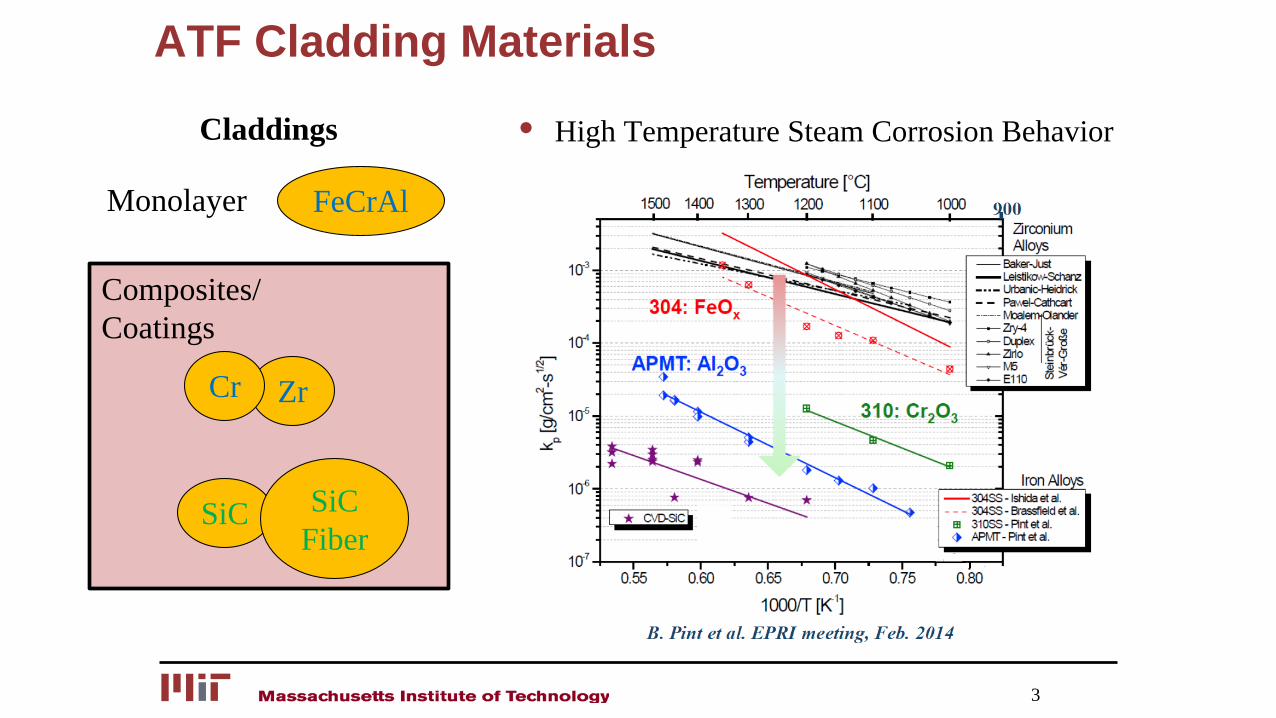
ATF Cladding Materials
3
FeCrAl
Zr
SiC SiCFiber
Cr
Claddings
Monolayer
Composites/Coatings
• High Temperature Steam Corrosion Behavior
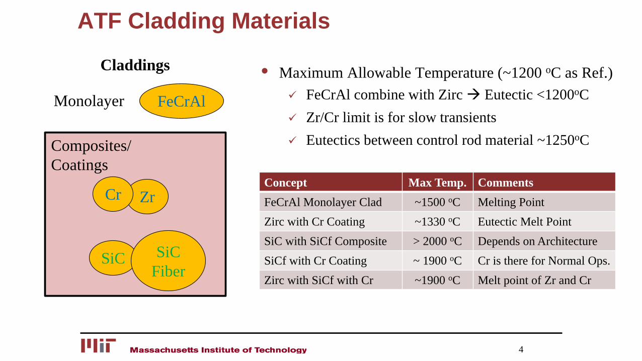
ATF Cladding Materials
4
FeCrAl
Claddings
Monolayer
Concept Max Temp. CommentsFeCrAl Monolayer Clad ~1500 oC Melting PointZirc with Cr Coating ~1330 oC Eutectic Melt PointSiC with SiCf Composite > 2000 oC Depends on ArchitectureSiCf with Cr Coating ~ 1900 oC Cr is there for Normal Ops.Zirc with SiCf with Cr ~1900 oC Melt point of Zr and Cr
• Maximum Allowable Temperature (~1200 oC as Ref.) FeCrAl combine with Zirc Eutectic <1200oC Zr/Cr limit is for slow transients Eutectics between control rod material ~1250oC
Zr
SiC SiCFiber
Cr
Composites/Coatings
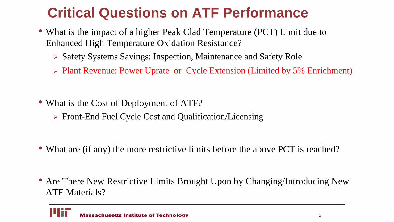
Critical Questions on ATF Performance• What is the impact of a higher Peak Clad Temperature (PCT) Limit due to
Enhanced High Temperature Oxidation Resistance? Safety Systems Savings: Inspection, Maintenance and Safety Role Plant Revenue: Power Uprate or Cycle Extension (Limited by 5% Enrichment)
• What is the Cost of Deployment of ATF? Front-End Fuel Cycle Cost and Qualification/Licensing
• What are (if any) the more restrictive limits before the above PCT is reached?
• Are There New Restrictive Limits Brought Upon by Changing/Introducing New ATF Materials?
5
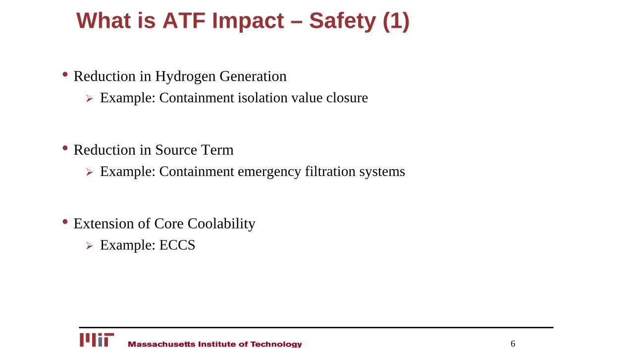
What is ATF Impact – Safety (1)
• Reduction in Hydrogen Generation Example: Containment isolation value closure
• Reduction in Source Term Example: Containment emergency filtration systems
• Extension of Core Coolability Example: ECCS
6
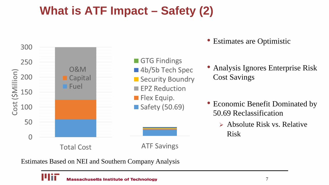
What is ATF Impact – Safety (2)
• Estimates are Optimistic
• Analysis Ignores Enterprise Risk Cost Savings
• Economic Benefit Dominated by 50.69 Reclassification Absolute Risk vs. Relative
Risk
7
Estimates Based on NEI and Southern Company Analysis
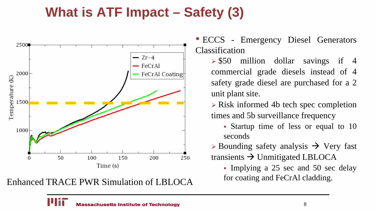
What is ATF Impact – Safety (3)
• ECCS - Emergency Diesel GeneratorsClassification
$50 million dollar savings if 4commercial grade diesels instead of 4safety grade diesel are purchased for a 2unit plant site. Risk informed 4b tech spec completiontimes and 5b surveillance frequency
Startup time of less or equal to 10seconds
Bounding safety analysis Very fasttransients Unmitigated LBLOCA
Implying a 25 sec and 50 sec delayfor coating and FeCrAl cladding.
8
Enhanced TRACE PWR Simulation of LBLOCA
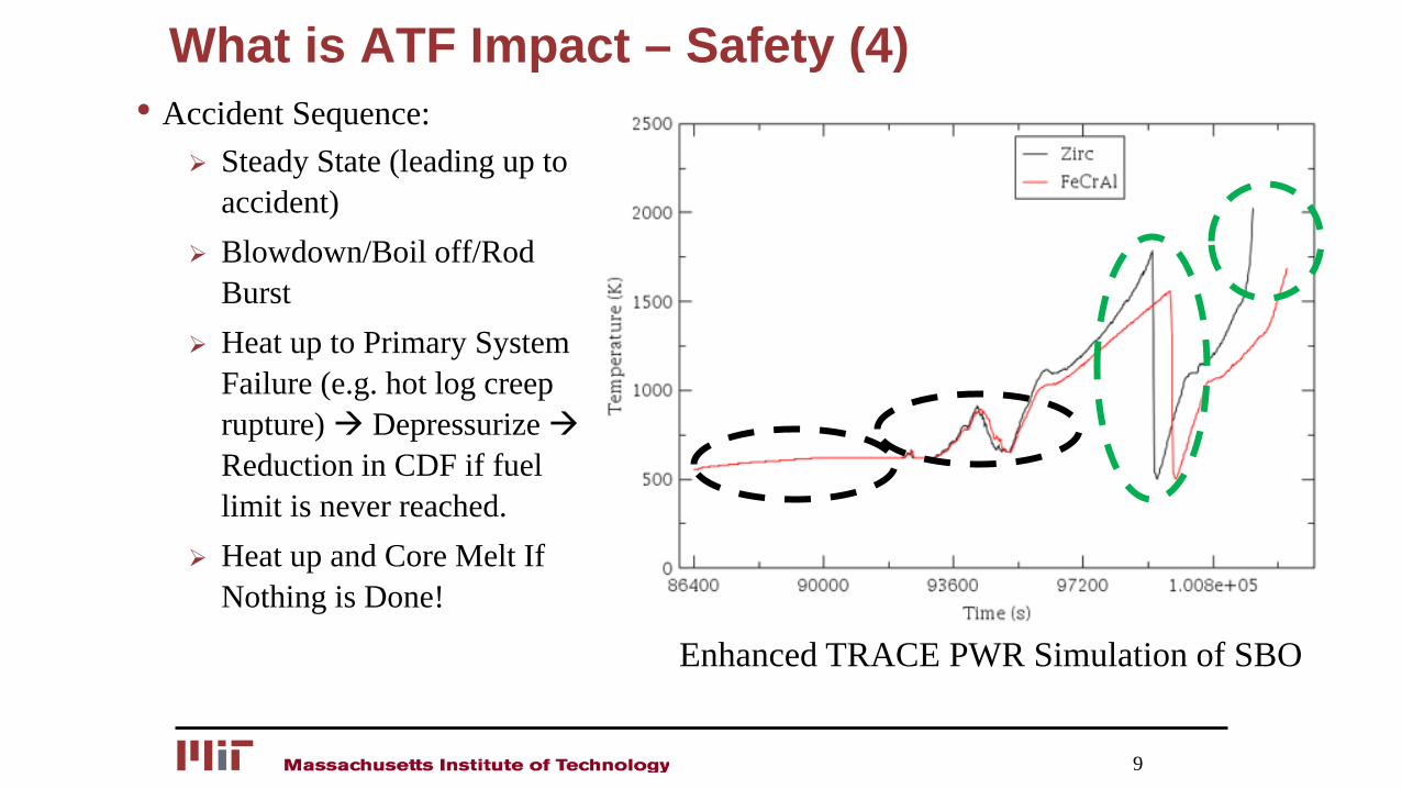
What is ATF Impact – Safety (4)• Accident Sequence:
Steady State (leading up to accident)
Blowdown/Boil off/Rod Burst
Heat up to Primary System Failure (e.g. hot log creep rupture) Depressurize Reduction in CDF if fuel limit is never reached.
Heat up and Core Melt If Nothing is Done!
9
Enhanced TRACE PWR Simulation of SBO
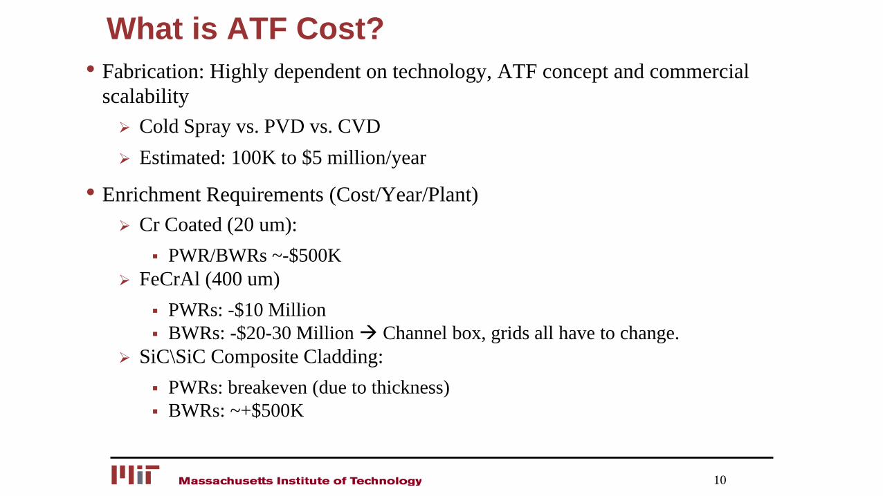
What is ATF Cost?• Fabrication: Highly dependent on technology, ATF concept and commercial
scalability Cold Spray vs. PVD vs. CVD Estimated: 100K to $5 million/year
• Enrichment Requirements (Cost/Year/Plant) Cr Coated (20 um):
PWR/BWRs ~-$500K FeCrAl (400 um)
PWRs: -$10 Million BWRs: -$20-30 Million Channel box, grids all have to change.
SiC\SiC Composite Cladding: PWRs: breakeven (due to thickness) BWRs: ~+$500K
10
What Are Restrictive Limits Before PCT? (1)
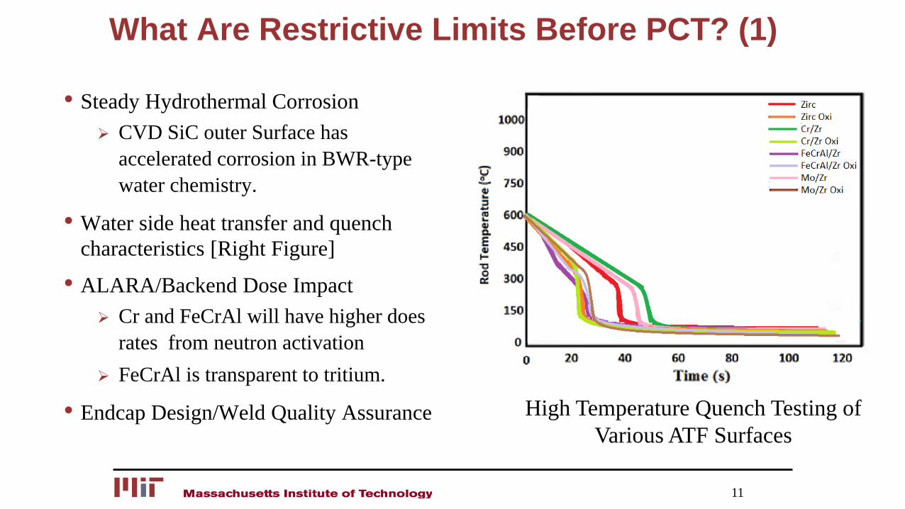
• Steady Hydrothermal Corrosion CVD SiC outer Surface has
accelerated corrosion in BWR-type water chemistry.
• Water side heat transfer and quench characteristics [Right Figure]
• ALARA/Backend Dose Impact Cr and FeCrAl will have higher does
rates from neutron activation FeCrAl is transparent to tritium.
• Endcap Design/Weld Quality Assurance
11
High Temperature Quench Testing of Various ATF Surfaces
What Are Restrictive Limits Before PCT? (2)
12
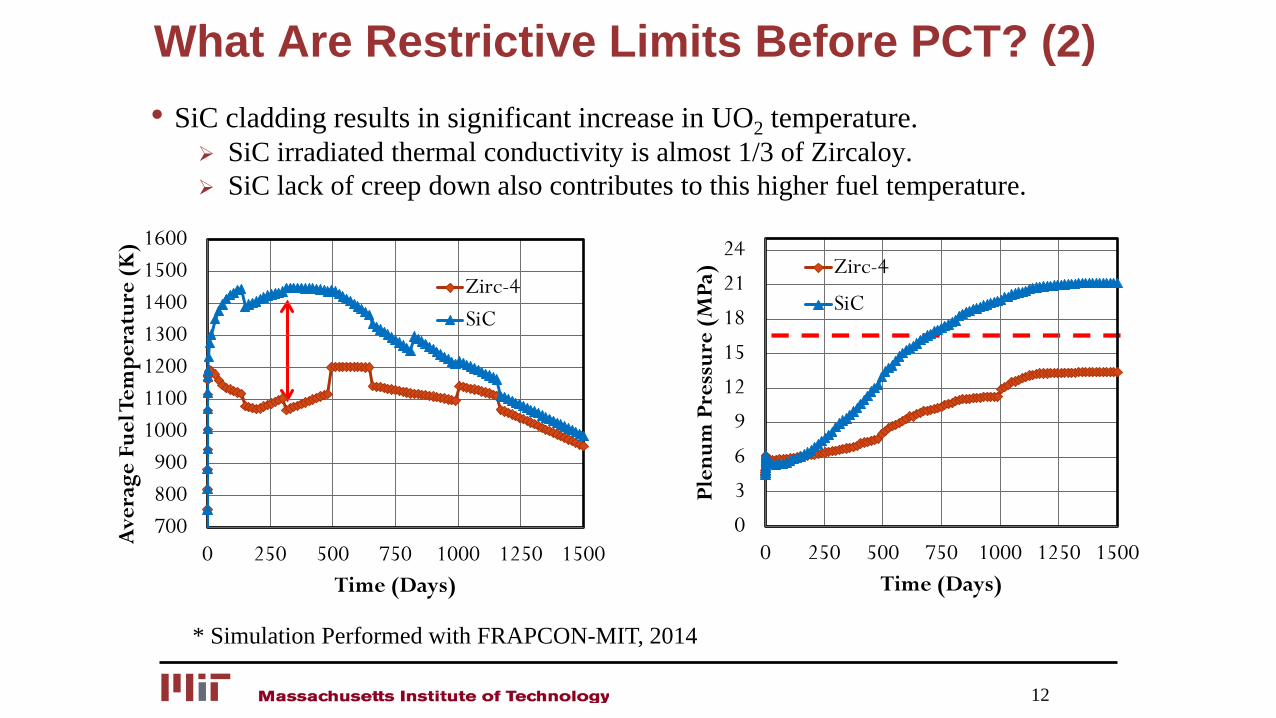
• SiC cladding results in significant increase in UO2 temperature. SiC irradiated thermal conductivity is almost 1/3 of Zircaloy. SiC lack of creep down also contributes to this higher fuel temperature.
* Simulation Performed with FRAPCON-MIT, 2014
700800900
1000110012001300140015001600
0 250 500 750 1000 1250 1500
Ave
rage
Fue
l Tem
pera
ture
(K
)
Time (Days)
Zirc-4SiC
0
3
6
9
12
15
18
21
24
0 250 500 750 1000 1250 1500
Plen
um P
ress
ure
(MPa
)
Time (Days)
Zirc-4
SiC
What Are New Restrictive Limits Before PCT? (1)
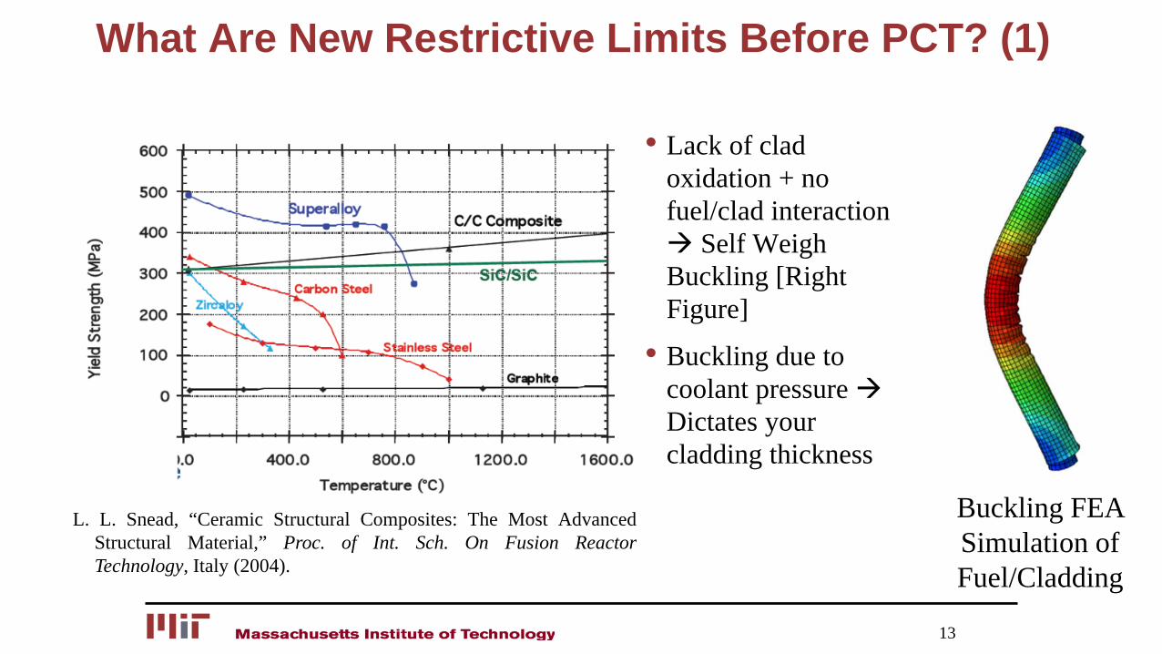
• Lack of clad oxidation + no fuel/clad interaction Self Weigh Buckling [Right Figure]
• Buckling due to coolant pressure Dictates your cladding thickness
13
L. L. Snead, “Ceramic Structural Composites: The Most AdvancedStructural Material,” Proc. of Int. Sch. On Fusion ReactorTechnology, Italy (2004).
Buckling FEA Simulation of Fuel/Cladding
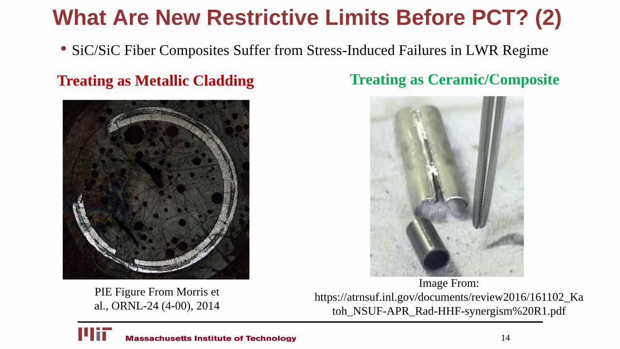
14
PIE Figure From Morris et al., ORNL-24 (4-00), 2014
Image From: https://atrnsuf.inl.gov/documents/review2016/161102_Ka
toh_NSUF-APR_Rad-HHF-synergism%20R1.pdf
Treating as Metallic Cladding Treating as Ceramic/Composite
What Are New Restrictive Limits Before PCT? (2)• SiC/SiC Fiber Composites Suffer from Stress-Induced Failures in LWR Regime
Concluding Remarks• ATFs have potential in Extending Coolability Time and Reducing Core
Damage Frequency
• New Regulatory Support is Required to Achieve Optimum Performance
• Much research needs to still focus on failure modes to allow for an informed UQ and PRA analysis.
• Close collaboration of all organizations involved in nuclear R&D is critical for ATF development. Lets Join Forces to Tackle the ATF Challenge Problem!
15
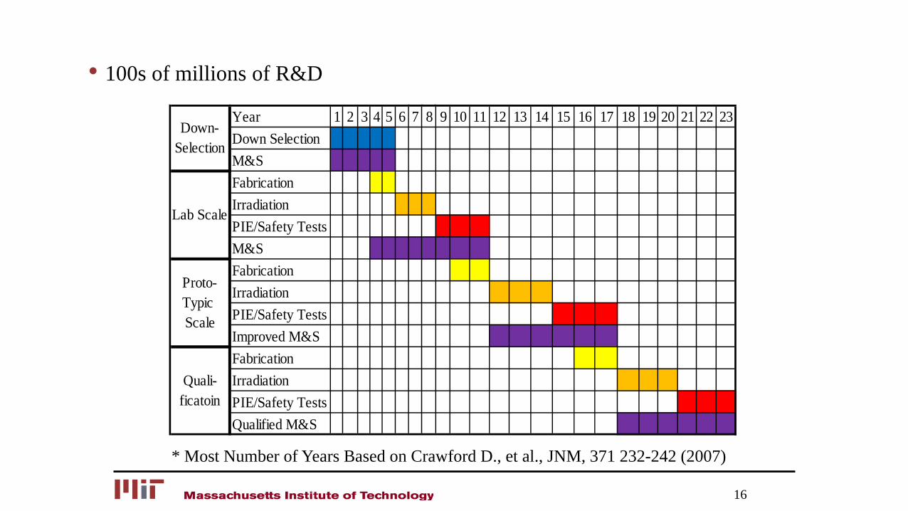
• 100s of millions of R&D
16
Year 1 2 3 4 5 6 7 8 9 10 11 12 13 14 15 16 17 18 19 20 21 22 23Down SelectionM&SFabricationIrradiationPIE/Safety TestsM&SFabricationIrradiationPIE/Safety TestsImproved M&SFabricationIrradiationPIE/Safety TestsQualified M&S
Down-Selection
Lab Scale
Proto-Typic Scale
Quali-ficatoin
* Most Number of Years Based on Crawford D., et al., JNM, 371 232-242 (2007)
17
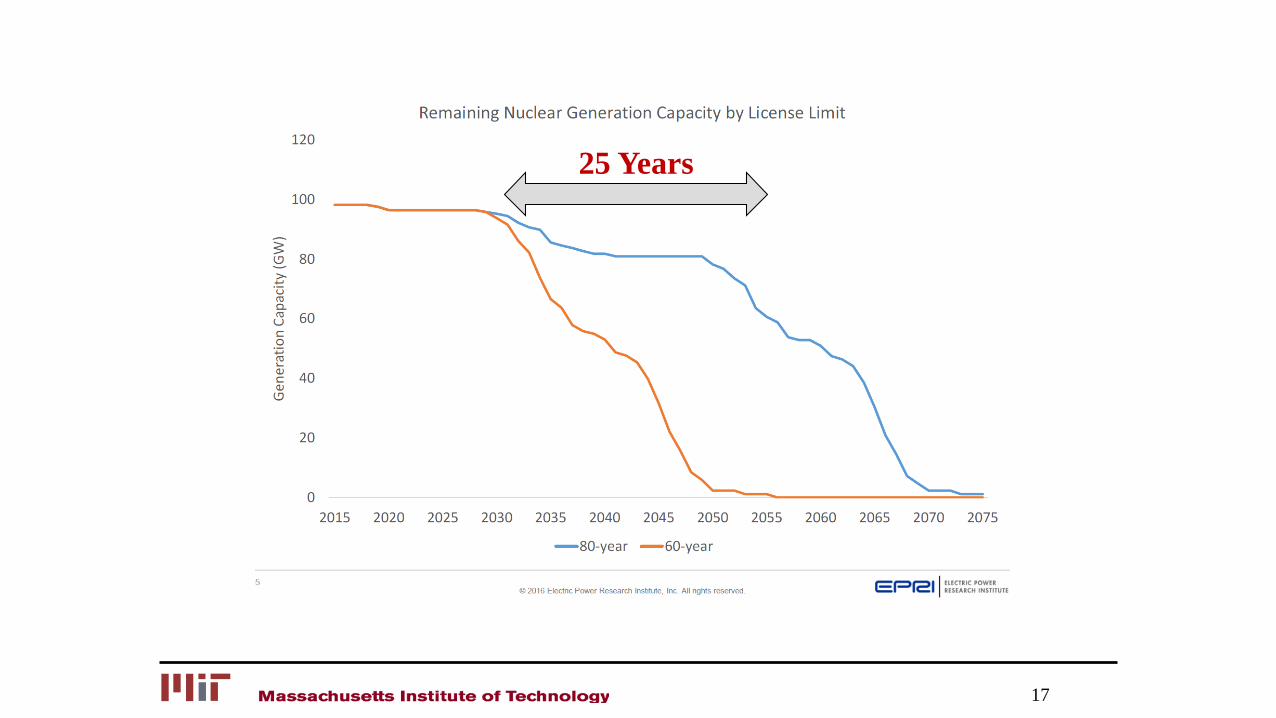
25 Years
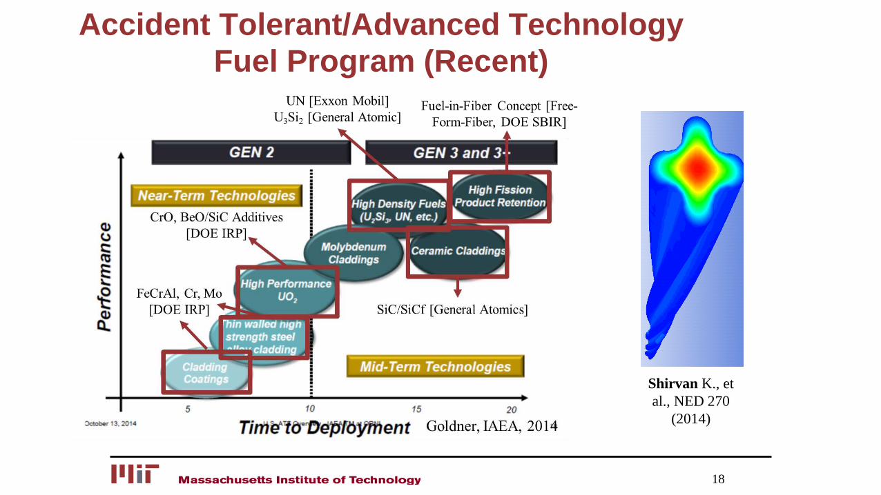
Accident Tolerant/Advanced Technology Fuel Program (Recent)
18
Shirvan K., et al., NED 270
(2014)
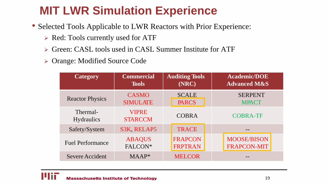
MIT LWR Simulation Experience• Selected Tools Applicable to LWR Reactors with Prior Experience:
Red: Tools currently used for ATF Green: CASL tools used in CASL Summer Institute for ATF Orange: Modified Source Code
19
Category Commercial Tools
Auditing Tools (NRC)
Academic/DOE Advanced M&S
Reactor Physics CASMO SIMULATE
SCALE PARCS
SERPENTMPACT
Thermal-Hydraulics
VIPRE STARCCM COBRA COBRA-TF
Safety/System S3K, RELAP5 TRACE --
Fuel Performance ABAQUSFALCON*
FRAPCON FRPTRAN
MOOSE/BISON FRAPCON-MIT
Severe Accident MAAP* MELCOR --
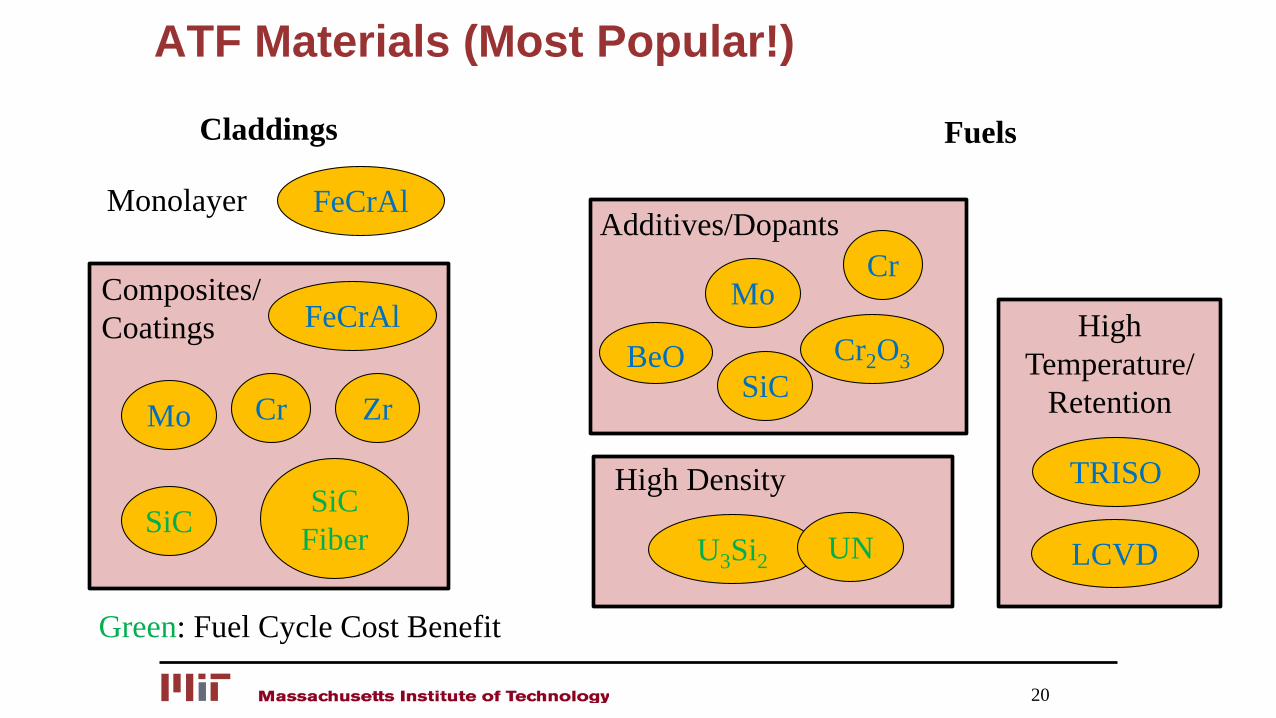
ATF Materials (Most Popular!)
20
FeCrAl
FeCrAl
Mo Zr
SiC SiCFiber
Cr
Cr2O3
Mo
SiCBeO
Cr
U3Si2 UN
TRISO
LCVD
Claddings
Monolayer
Composites/Coatings
High Density
Fuels
Additives/Dopants
High Temperature/
Retention
Green: Fuel Cycle Cost Benefit
What is ATF Impact – Revenue (1)
• Power Uprates: No longer limited by PCT during LOCAs and Zircaloy Hydride Formation BWRs: 20% uprate without ATFs PWRs: Many SGs Replacements Have Already Been Placed
• Cycle Length Extensions: No longer limited by Zircaloy Hydride Formation BWRs: Already at 2 years PWRs: Reduction in $6 to $10 million/year in Regulated Markets.
21
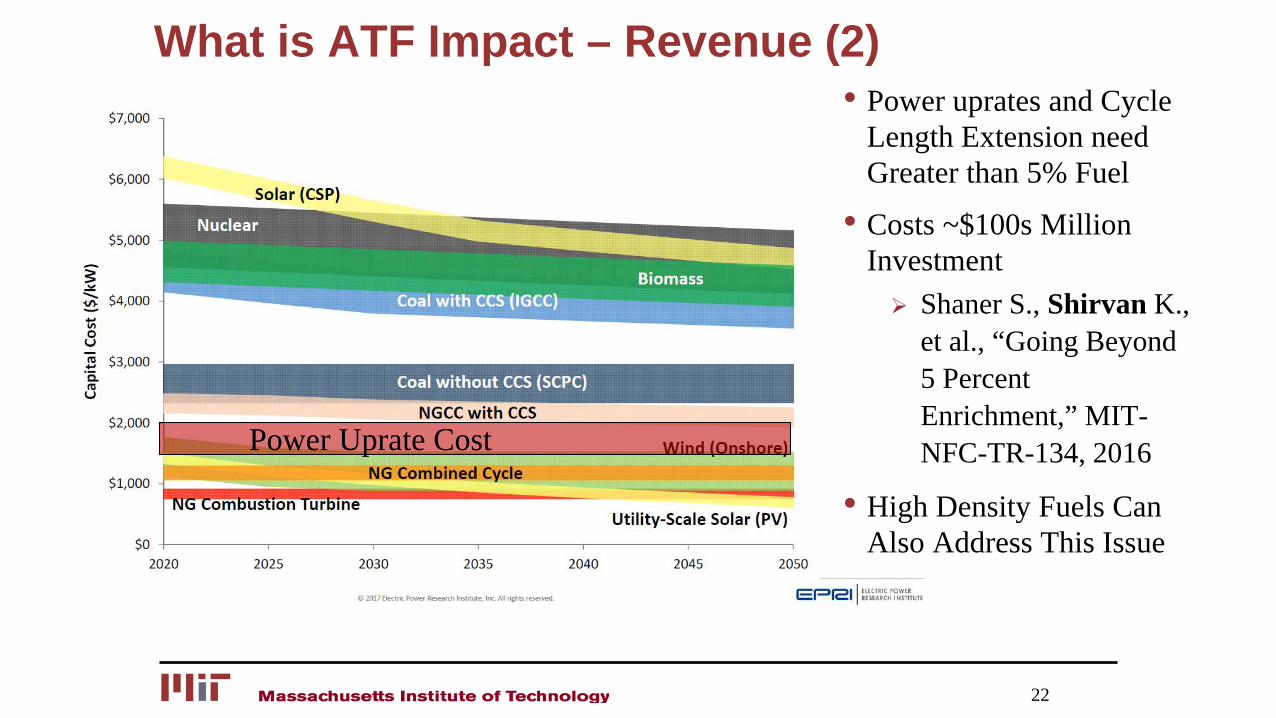
What is ATF Impact – Revenue (2)
22
• Power uprates and Cycle Length Extension need Greater than 5% Fuel
• Costs ~$100s Million Investment Shaner S., Shirvan K.,
et al., “Going Beyond 5 Percent Enrichment,” MIT-NFC-TR-134, 2016
• High Density Fuels Can Also Address This Issue
Power Uprate Cost
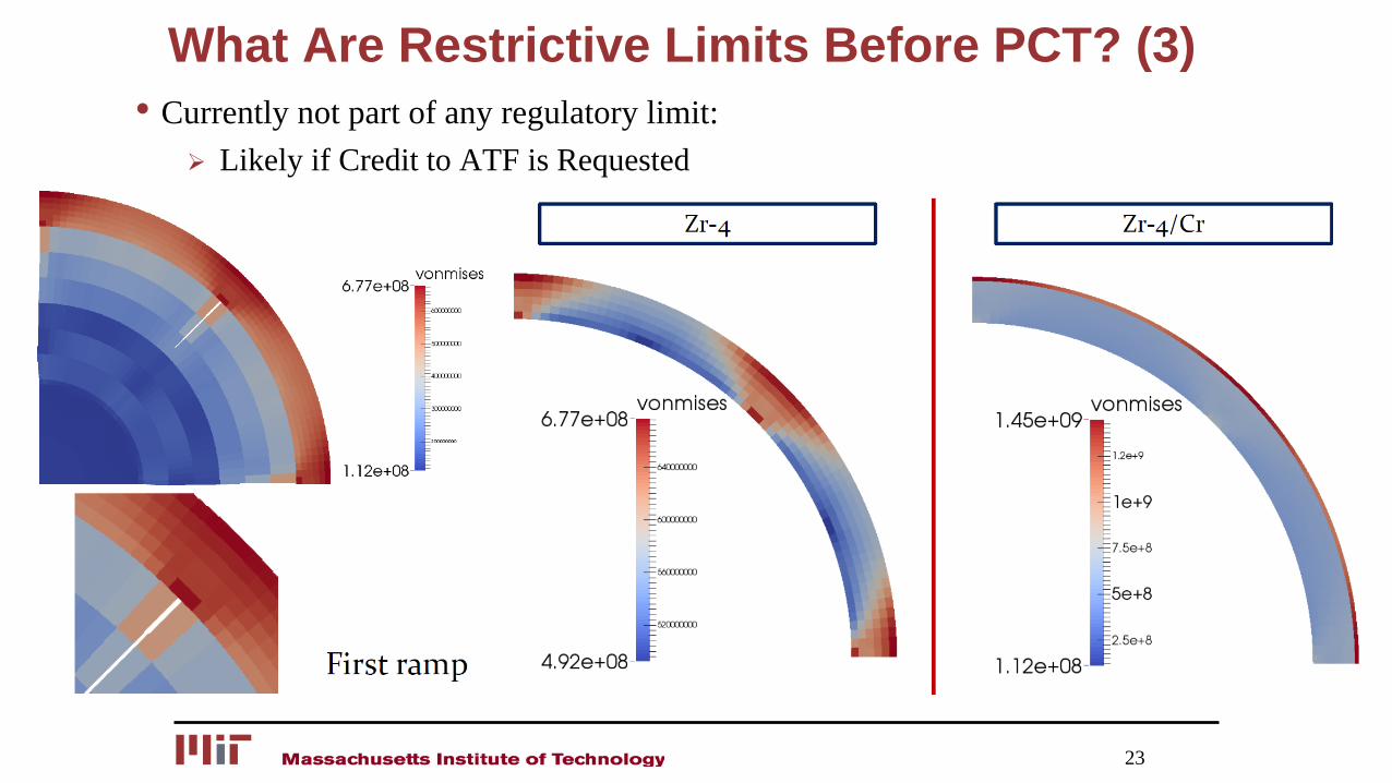
What Are Restrictive Limits Before PCT? (3)• Currently not part of any regulatory limit:
Likely if Credit to ATF is Requested
23
Integration of ATF with FLEX• Following the Fukushima accident, the nuclear industry has invested more than
$4 billion on “FLEX”, a diverse and flexible approach to mitigate the potential impacts of unforeseen events.
• The FLEX program implementation aimed at improving safety of used fuel pool cooling, containment integrity and accident response time. The ATF primary aim has been to address the fall-out hydrogen explosion and rapid progression of severe accidents observed in Fukushima.
• While the main FLEX equipment has been already purchased, the maintenance and its classification such as for hardened vents, could potentially be relaxed with ATF implementation.
• The combination of FLEX and ATF may allow for more flexible maintenance during plant shutdown by allowing variety of safety trains to be offline. The implemented emergency drills and centers may also become unnecessary.
24
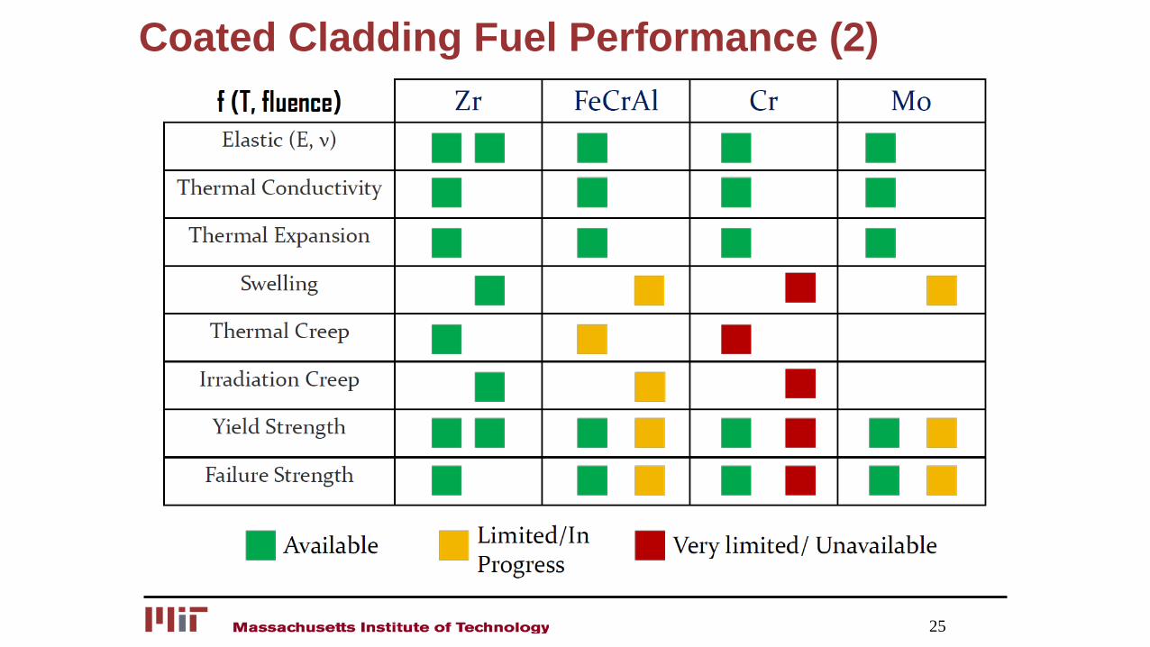
Coated Cladding Fuel Performance (2)
25
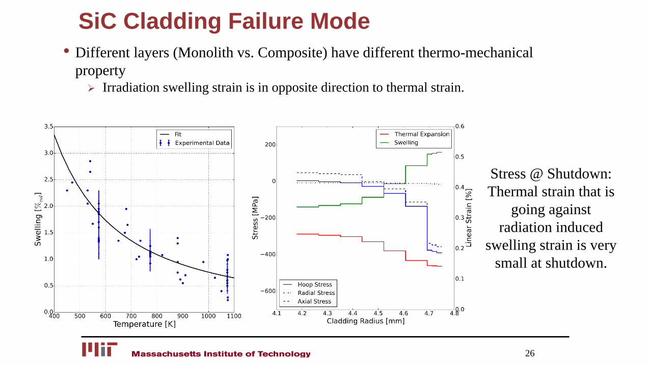
SiC Cladding Failure Mode• Different layers (Monolith vs. Composite) have different thermo-mechanical
property Irradiation swelling strain is in opposite direction to thermal strain.
26
Stress @ Shutdown:Thermal strain that is
going against radiation induced
swelling strain is very small at shutdown.
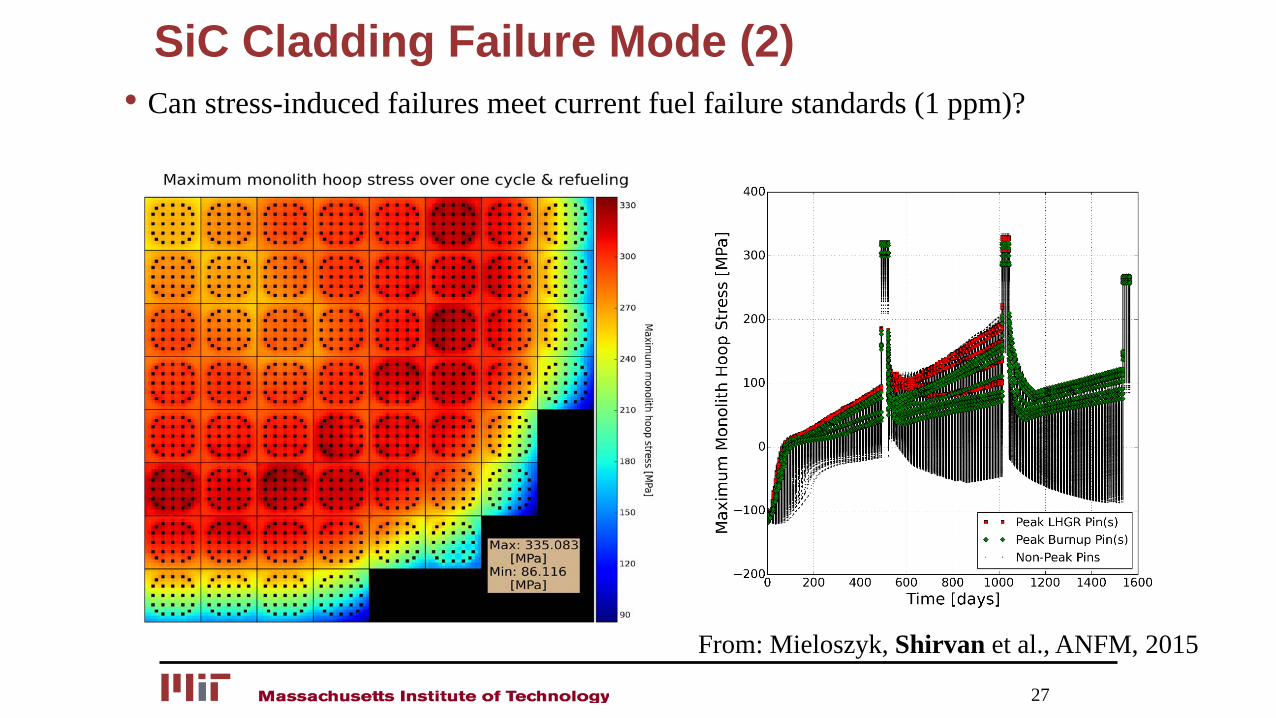
SiC Cladding Failure Mode (2)• Can stress-induced failures meet current fuel failure standards (1 ppm)?
27
From: Mieloszyk, Shirvan et al., ANFM, 2015
SiC Integral Fuel Performance (3)
28
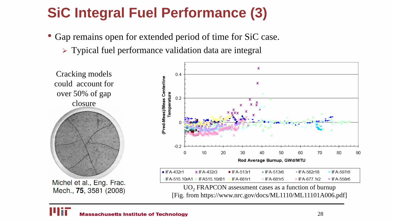
• Gap remains open for extended period of time for SiC case. Typical fuel performance validation data are integral
UO2 FRAPCON assessment cases as a function of burnup[Fig. from https://www.nrc.gov/docs/ML1110/ML11101A006.pdf]
Cracking models could account for over 50% of gap
closure
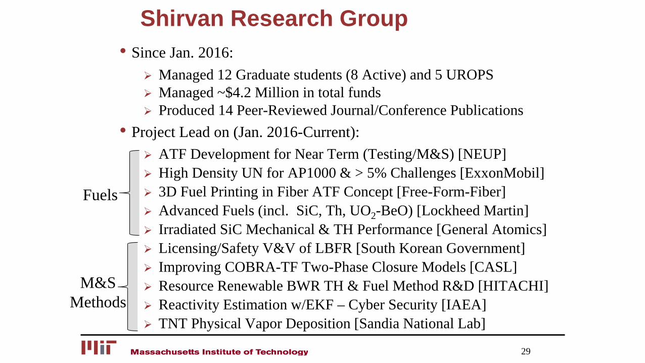
Shirvan Research Group• Since Jan. 2016:
Managed 12 Graduate students (8 Active) and 5 UROPS Managed ~$4.2 Million in total funds Produced 14 Peer-Reviewed Journal/Conference Publications
• Project Lead on (Jan. 2016-Current): ATF Development for Near Term (Testing/M&S) [NEUP] High Density UN for AP1000 & > 5% Challenges [ExxonMobil] 3D Fuel Printing in Fiber ATF Concept [Free-Form-Fiber] Advanced Fuels (incl. SiC, Th, UO2-BeO) [Lockheed Martin] Irradiated SiC Mechanical & TH Performance [General Atomics] Licensing/Safety V&V of LBFR [South Korean Government] Improving COBRA-TF Two-Phase Closure Models [CASL] Resource Renewable BWR TH & Fuel Method R&D [HITACHI] Reactivity Estimation w/EKF – Cyber Security [IAEA] TNT Physical Vapor Deposition [Sandia National Lab]
Fuels
M&S Methods
29
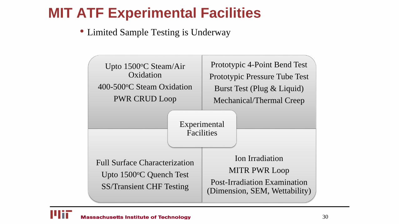
MIT ATF Experimental Facilities• Limited Sample Testing is Underway
30
Upto 1500oC Steam/Air Oxidation
400-500oC Steam OxidationPWR CRUD Loop
Prototypic 4-Point Bend TestPrototypic Pressure Tube Test
Burst Test (Plug & Liquid)Mechanical/Thermal Creep
Full Surface CharacterizationUpto 1500oC Quench TestSS/Transient CHF Testing
Ion IrradiationMITR PWR Loop
Post-Irradiation Examination (Dimension, SEM, Wettability)
Experimental Facilities
DOE ATF Integrated Research Project
31
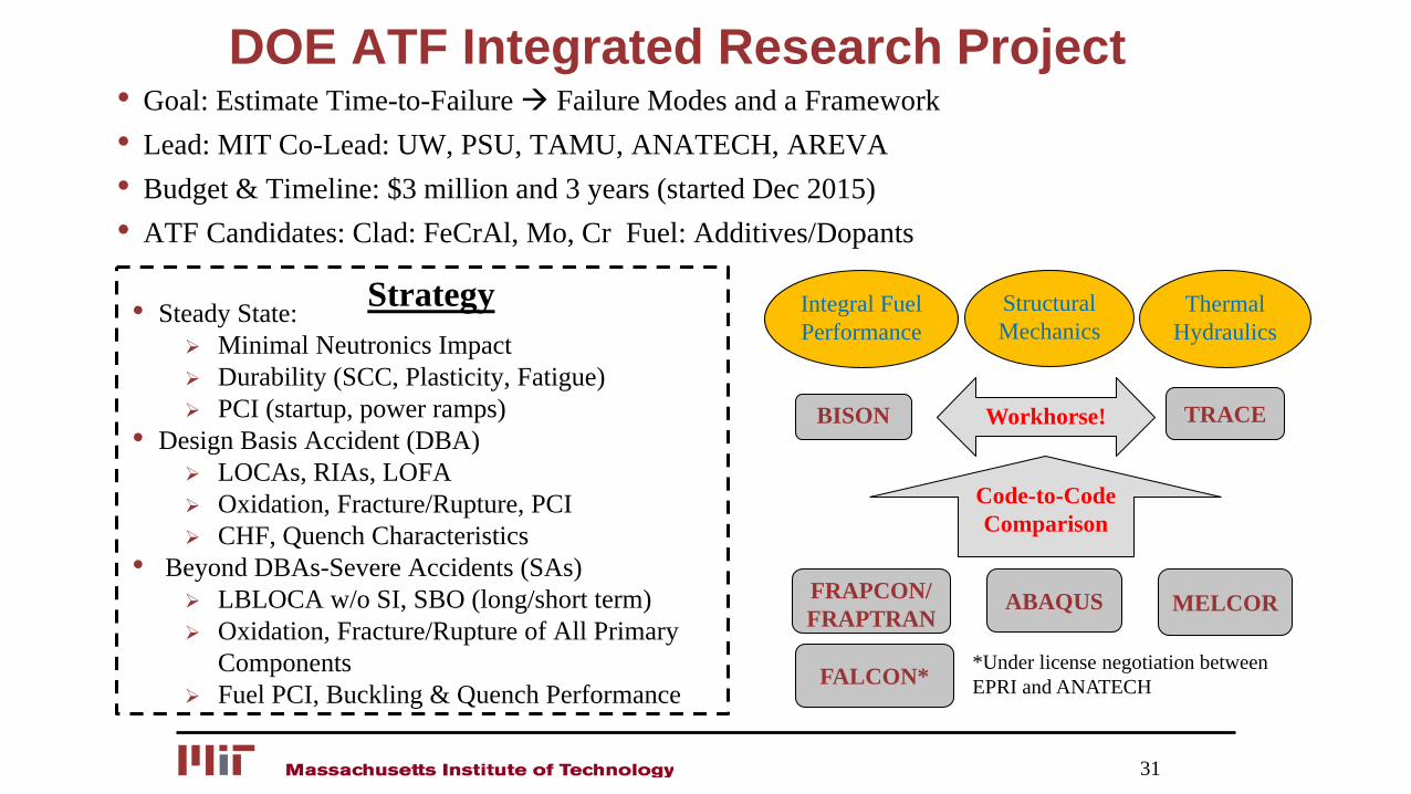
• Goal: Estimate Time-to-Failure Failure Modes and a Framework• Lead: MIT Co-Lead: UW, PSU, TAMU, ANATECH, AREVA• Budget & Timeline: $3 million and 3 years (started Dec 2015)• ATF Candidates: Clad: FeCrAl, Mo, Cr Fuel: Additives/Dopants
BISON
FRAPCON/ FRAPTRAN
Integral Fuel Performance
ABAQUS
Structural Mechanics
Thermal Hydraulics
TRACE
MELCOR
FALCON*
Workhorse!
Code-to-Code Comparison
*Under license negotiation between EPRI and ANATECH
• Steady State: Minimal Neutronics Impact Durability (SCC, Plasticity, Fatigue) PCI (startup, power ramps)
• Design Basis Accident (DBA) LOCAs, RIAs, LOFA Oxidation, Fracture/Rupture, PCI CHF, Quench Characteristics
• Beyond DBAs-Severe Accidents (SAs) LBLOCA w/o SI, SBO (long/short term) Oxidation, Fracture/Rupture of All Primary
Components Fuel PCI, Buckling & Quench Performance
Strategy
Estimation of Time-to-Failure
32
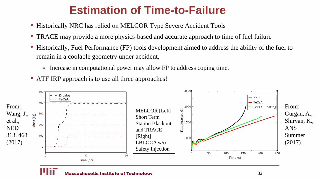
• Historically NRC has relied on MELCOR Type Severe Accident Tools• TRACE may provide a more physics-based and accurate approach to time of fuel failure• Historically, Fuel Performance (FP) tools development aimed to address the ability of the fuel to
remain in a coolable geometry under accident,
Increase in computational power may allow FP to address coping time.
• ATF IRP approach is to use all three approaches!
MELCOR [Left] Short Term Station Blackout and TRACE [Right] LBLOCA w/o Safety Injection
From: Wang, J., et al., NED 313, 468 (2017)
From: Gurgan, A., Shirvan, K., ANS Summer (2017)
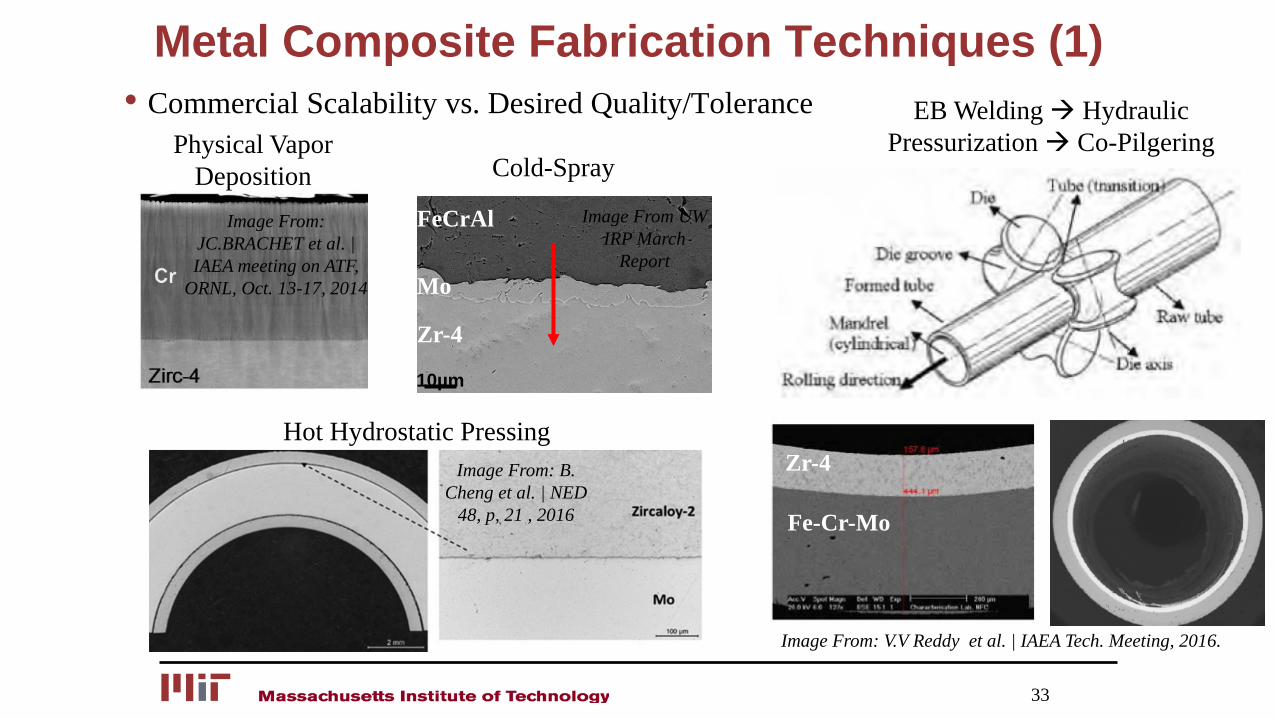
Metal Composite Fabrication Techniques (1)• Commercial Scalability vs. Desired Quality/Tolerance
33
Physical Vapor Deposition
Image From: JC.BRACHET et al. | IAEA meeting on ATF,
ORNL, Oct. 13-17, 2014
10µm
Image From UW IRP March
ReportMo
Zr-4
FeCrAl
Cold-Spray
Hot Hydrostatic PressingImage From: B.
Cheng et al. | NED 48, p, 21 , 2016
EB Welding Hydraulic Pressurization Co-Pilgering
Zr-4
Fe-Cr-Mo
Image From: V.V Reddy et al. | IAEA Tech. Meeting, 2016.
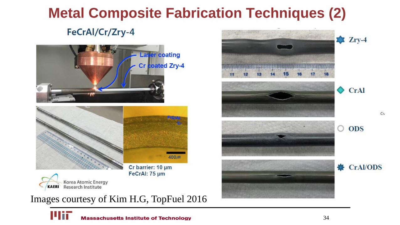
Metal Composite Fabrication Techniques (2)
34
Images courtesy of Kim H.G, TopFuel 2016
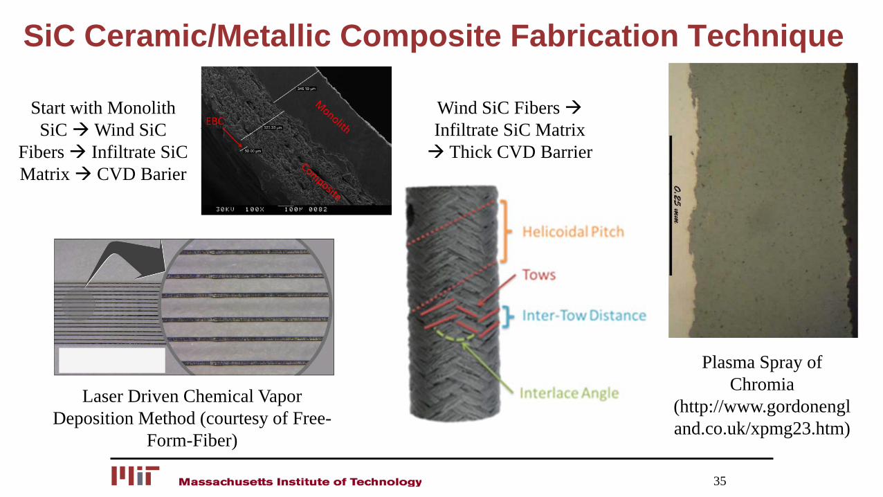
SiC Ceramic/Metallic Composite Fabrication Technique
35
Laser Driven Chemical Vapor Deposition Method (courtesy of Free-
Form-Fiber)
Start with Monolith SiCWind SiC
Fibers Infiltrate SiCMatrix CVD Barier
Wind SiC Fibers Infiltrate SiC Matrix Thick CVD Barrier
Plasma Spray of Chromia
(http://www.gordonengland.co.uk/xpmg23.htm)
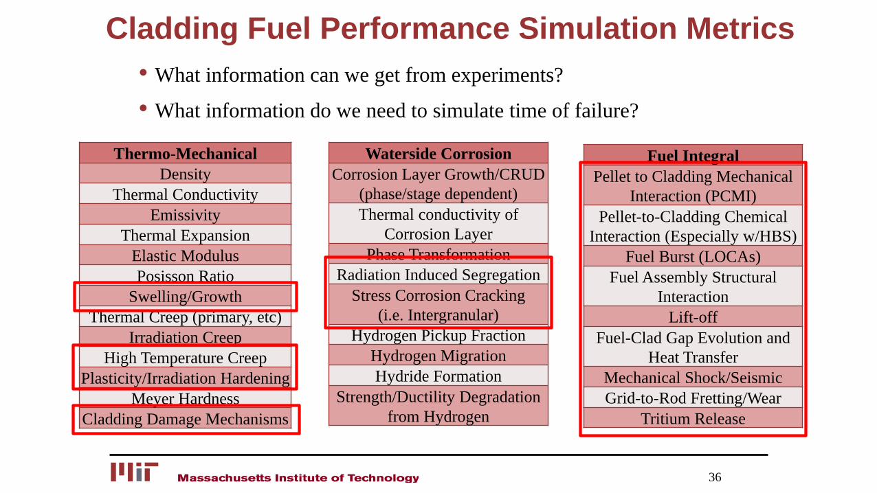
Cladding Fuel Performance Simulation Metrics
Thermo-MechanicalDensity
Thermal ConductivityEmissivity
Thermal ExpansionElastic ModulusPosisson Ratio
Swelling/GrowthThermal Creep (primary, etc)
Irradiation CreepHigh Temperature Creep
Plasticity/Irradiation HardeningMeyer Hardness
Cladding Damage Mechanisms
36
Waterside CorrosionCorrosion Layer Growth/CRUD
(phase/stage dependent)Thermal conductivity of
Corrosion LayerPhase Transformation
Radiation Induced SegregationStress Corrosion Cracking
(i.e. Intergranular)Hydrogen Pickup Fraction
Hydrogen MigrationHydride Formation
Strength/Ductility Degradation from Hydrogen
• What information can we get from experiments?
• What information do we need to simulate time of failure?
Fuel IntegralPellet to Cladding Mechanical
Interaction (PCMI)Pellet-to-Cladding Chemical
Interaction (Especially w/HBS)Fuel Burst (LOCAs)
Fuel Assembly StructuralInteraction
Lift-offFuel-Clad Gap Evolution and
Heat TransferMechanical Shock/SeismicGrid-to-Rod Fretting/Wear
Tritium Release
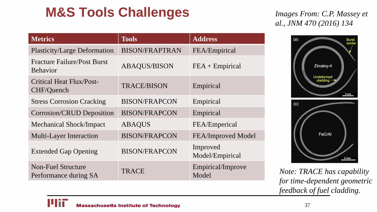
M&S Tools Challenges
37
Metrics Tools AddressPlasticity/Large Deformation BISON/FRAPTRAN FEA/EmpiricalFracture Failure/Post Burst Behavior ABAQUS/BISON FEA + Empirical
Critical Heat Flux/Post-CHF/Quench TRACE/BISON Empirical
Stress Corrosion Cracking BISON/FRAPCON EmpiricalCorrosion/CRUD Deposition BISON/FRAPCON EmpiricalMechanical Shock/Impact ABAQUS FEA/EmpericalMulti-Layer Interaction BISON/FRAPCON FEA/Improved Model
Extended Gap Opening BISON/FRAPCON Improved Model/Empirical
Non-Fuel Structure Performance during SA TRACE Empirical/Improve
Model
Images From: C.P. Massey et al., JNM 470 (2016) 134
Note: TRACE has capability for time-dependent geometric feedback of fuel cladding.
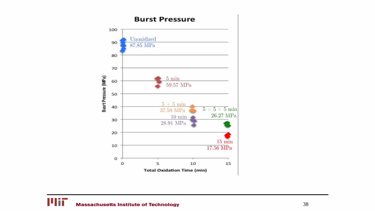
38
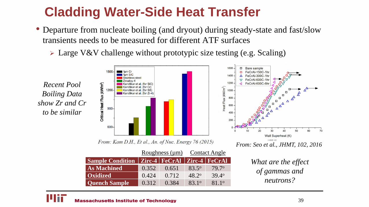
Cladding Water-Side Heat Transfer• Departure from nucleate boiling (and dryout) during steady-state and fast/slow
transients needs to be measured for different ATF surfaces Large V&V challenge without prototypic size testing (e.g. Scaling)
39
What are the effect of gammas and
neutrons?
Recent Pool Boiling Data
show Zr and Cr to be similar
From: Seo et al., JHMT, 102, 2016
Sample Condition Zirc-4 FeCrAl Zirc-4 FeCrAlAs Machined 0.352 0.651 83.5o 79.7o
Oxidized 0.424 0.712 48.2o 39.4o
Quench Sample 0.312 0.384 83.1o 81.1o
Roughness (µm) Contact Angle
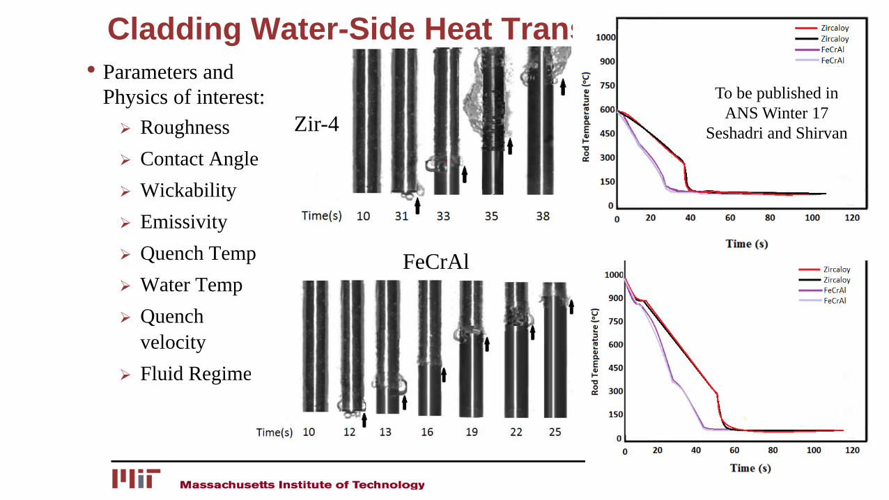
Cladding Water-Side Heat Transfer (2)• Parameters and
Physics of interest: Roughness Contact Angle Wickability Emissivity Quench Temp Water Temp Quench
velocity Fluid Regime
40
Zir-4
FeCrAl
To be published in ANS Winter 17
Seshadri and Shirvan
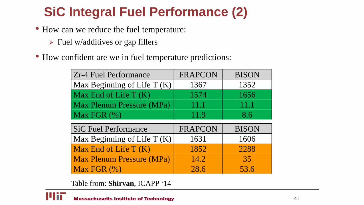
SiC Integral Fuel Performance (2)• How can we reduce the fuel temperature:
Fuel w/additives or gap fillers
• How confident are we in fuel temperature predictions:
41
SiC Fuel Performance FRAPCON BISONMax Beginning of Life T (K) 1631 1606Max End of Life T (K) 1852 2288Max Plenum Pressure (MPa) 14.2 35Max FGR (%) 28.6 53.6
Zr-4 Fuel Performance FRAPCON BISONMax Beginning of Life T (K) 1367 1352Max End of Life T (K) 1574 1656Max Plenum Pressure (MPa) 11.1 11.1Max FGR (%) 11.9 8.6
Table from: Shirvan, ICAPP ‘14
• Veiw of NPP licensing
42

![The Basic Buddhism · pepYfk[jcmi ;j?/ ahkrj J, sj fv / anfm>e” r;/ rnej b;kc;je{kfc;j/ ekfc;jmm¹ glC f/ [Pspj Fes[Kc;j akY]i;cF/ bru f; rtnf/ trf;rtnf/ hG’ frtnftJ;jHeU hf rtnf[mt](https://img.pdfslide.net/doc/110x75/6082c4b68ee8584709632a2c/the-basic-pepyfkjcmi-j-ahkrj-j-sj-fv-anfmea-r-rnej-bkcjekfcj.jpg)
![1. Zastosowania matematyki - Mieloszyk E. Karta przedmiotu ... · Jakubiec W., Malinowski J.: Metrologia wielkości geometrycznych WNT Warszawa 2007 [6]. Sydenham P. H., Podręcznik](https://img.pdfslide.net/doc/110x75/5c75e38209d3f28c0f8bb222/1-zastosowania-matematyki-mieloszyk-e-karta-przedmiotu-jakubiec-w.jpg)