Embed Size (px)
Citation preview

Riverstone Security and Operations Guide | Riverstone Networks Advanced Technical Documentation
Support Home | Documentation Home |
<=Previous RSO Home Next =>
Riverstone Security and Operations Guide - Index View PDF
Andrew Walden, Riverstone Networks
Table of ContentsIntroduction
RS Hardware
RS 1000 RS 3000 RS 8x00 RS 16000 RS 38000 Speeds and Feeds RS Software
Initial Setup
Linecards and Power Supplies Flash Cards Physical Security Powering Up Consoling In Observing the Boot Process NVRAM Mode TFTP Boot Setting System Passwords Configuring the Management Port (en0) Choosing System Code Upgrading the OS Configuring the Loopback Interface Setting Up Secure Access and Services
Telnet SSH RADIUS Authentication RADIUS Accounting Cistron RADIUS TACACS+ Authentication TACACS+ Accounting NTP - Network Time Protocol IGP Authentication BGP Authentication BGP Damping ACLs Miscellaneous Security and Performance Features Fragments Rate Limiting Broadcast Traffic
http://www.riverstonenet.com/support/rso/index.shtml (1 of 2) [11/15/2002 11:03:39 AM]

Riverstone Security and Operations Guide | Riverstone Networks Advanced Technical Documentation
IP Reverse Flows IP Reverse Path Forwarding Network Monitoring
SNMP SNMP Configuration Enabling and Disabling MIBs SNMP Traps SNMP Tools MRTG Syslog Monitoring Attacks Malformed Packets Fragmented Packets Basic DOS Directed Broadcast Distributed DOS Managing Infrastructure
Managing Changes Using RCS Managing IP Space Inventory and Other Info Silos (OSS) You need a Security Policy Acceptable Use Policy Abuse Contacts Putting it all together - Sample Configuration
References
Acknowledgements
<=Previous RSO Home Next =>
© 2001-2002, Riverstone Networks, Inc. All rights reserved. Privacy Statement Terms of Use Feedback
http://www.riverstonenet.com/support/rso/index.shtml (2 of 2) [11/15/2002 11:03:39 AM]

Riverstone Security and Operations Guide | Riverstone Networks Advanced Technical Documentation
Support Home | Documentation Home |
<=Previous RSO Home Next =>
Riverstone Security and Operations Guide - Introduction
Starting with its humble beginnings as a DOD science project and now a vital part of many businesses and lives, the Internet has grown from a tinkerer's toy to an indispensable part of modern life. Private citizens and businesses have both come to depend upon the Internet and power that it brings to enhance productivity and lives.
The glue that holds the Internet together is the collection of IP routers that push packets around at nearly the speed of light and groom and route traffic as required. The security and stability of Internet routers is critical as the failure of any one device on the public Internet can lead to interruption or disruption of service or performance to large numbers of people and systems.
This document offers advice on best current practices, standard operating procedures and common sense tips for securing and managing Riverstone Networks routers on the public Internet. Since Riverstone products are widely used by service providers, the information in this document is directed towards helping to solve some of the unique challenges that service providers face.
This document is meant to be a supplement to the Riverstone Product Manuals and other documentation available on the Riverstone website. It is assumed that the reader has proficiency with IP Routing concepts in general and has at least basic familiarity with Riverstone products. Other documentation that is of particular use for those ramping up on the Riverstone family includes:
● The User's Guide: contains descriptions and examples of concepts and configurations● The CLI Guide: Syntax and reference for specific commands● The Message Guide: Descriptions and explanations of system messages
Many aspects of managing network infrastructure entail using software and tools external to the router itself. When possible, this document will demonstrate the use of open-source tools in the examples and will provide brief details of the configuration and use of the tools when doing so will add value and save you time. This document will focus and recommend IETF and IEEE standards for any protocols suggested. By using standards based protocols and technologies on your network you can position your network for continued growth and flexibility.
The Internet is a living entity that is constantly in a state of flux. Because of this, this document will be updated as needed to reflect the current nature of network technologies and practices. You may want to check with the Riverstone website, http://www.rstn.net, to ensure that you have the latest version of this or any other Riverstone documents.
<=Previous RSO Home Next =>
© 2001-2002, Riverstone Networks, Inc. All rights reserved. Privacy Statement Terms of Use Feedback
http://www.riverstonenet.com/support/rso/introduction.shtml [11/15/2002 11:03:40 AM]

Riverstone Security and Operations Guide | Riverstone Networks Advanced Technical Documentation
Support Home | Documentation Home |
<=Previous RSO Home Next =>
Riverstone Security and Operations Guide - Riverstone Hardware
Product Overview
This chapter provides an overview of all the switch/routers in the RS product line. If you're new to the RS platform, then this section will provide a brief overview to the RS product line.
RS 1000
The RS 1000 is a 2U switch/router with a 12Gb backplane and supports 128Mb of RAM. The RS 1000 has redundant AC or DC power supplies. The RS 1000 is a 2-slot modular chassis. Most of the linecards between the RS 1000 and RS 3000 are interchangeable. The supported linecards for the RS 1000/RS 3000 are listed in the table below.
RS 1000/3000 Supported Linecards
● 2 Port Gig-E Card● 2 Port Gig-E (MPLS Enabled) Card● 2 Port HSSI Card ● 8 Port 10/100 FX Card● 16 Port 10/100 TX Card● 2 Port Multi-rate WAN Card (Supports 4 T1s/2 T3s or a mix of both)● 2 Port Multi-rate ATM Module (Supports 2 T3/E3/OC3 or a mix of each)
RS 3000
The RS 3000 is a 2U switch/router with a 20Gb backplane and supports 128Mb or 256Mb of RAM. The RS 3000 has redundant AC or DC power supplies. The RS 3000 is a 4-slot partially modular chassis. Two of the slots filled with fixed 16-port 10/100 TX cards. The linecards between the RS 1000 and RS 3000 are interchangeable. The other two slots are free for any of the supported linecards listed above.
RS 8000
The RS 8000 is a 5U switch/router with a 32Gb backplane and supports 128Mb, 256Mb or 512Mb of RAM. The RS 8000 has redundant AC or DC power supplies, and redundant control modules (CM). The RS 8000 is an 8-slot modular chassis. Seven of the slots are available for linecards unless a redundant CM is used which leaves six usable slots. The linecards available for the RS 8000 are listed below.
RS 8000/8600 Supported Linecards
● 2 Port Gig-E Module● 2 Port Gig-E MPLS Module● 8 Port 10/100 FX Module● 8 Port 10/100 TX Module● 16 Port 10/100 FX Module● 16 Port 10/100 TX Module● 2 Port Multi-rate WAN Module (Supports 4 T1/E1/ 2 T3 or a mix of both)● 2 Port Channelized T3 Module● 2 Port POS OC3/STM1 MPLS Module● 4 Port POS OC3/STM1 Module● 2 Port POS OC12/STM4 Module● 2 Port Multi-rate ATM Module (Supports 2 T3/E3/OC3 or mix of both)● 1 + 1 OC-12c/STM-4 ATM Module
http://www.riverstonenet.com/support/rso/rs_hardware.shtml (1 of 5) [11/15/2002 11:03:42 AM]

Riverstone Security and Operations Guide | Riverstone Networks Advanced Technical Documentation
● 1-port OC-48c SRP Module● SRP Bridge Module (required for SRP)
RS 8600
The RS 8600 is an 11U switch/router with a 64Gb backplane and supports 128Mb, 256Mb or 512Mb of RAM. The RS 8600 has redundant AC or DC power supplies, redundant control modules (CM) and redundant switch fabrics. The RS 8600 is a 16-slot modular chassis. Fifteen of the slots are available for linecards unless a redundant CM is used which leaves fourteen usable slots. The RS 8600 linecards are interchangeable with the RS 8000 and are listed in the table above.
RS 16000
The RS 16000 is a 5U switch/router with a 170Gb backplane and supports 256Mb or 512Mb of RAM. The RS 16000 has redundant AC or DC power supplies and redundant control modules (CM). The RS 16000 is an 8-slot modular chassis. Seven of the slots are available for linecards unless a redundant CM is used which leaves six usable slots. The linecards that are available for the RS 16000 are listed in the table below.
RS 16000 Supported Interfaces
● 8 Port Gig-E Card● 4 GbE Lambda on uni-directional CWDM (long range) ● 64 Port 10/100 Module
RS 38000
The RS 38000 is a 20U switch/router with a 170Gb backplane and supports 256Mb or 512Mb of RAM. The RS 38000 has redundant AC or DC power supplies, redundant control modules (CM) and redundant switch fabrics. The RS 38000 is NEBS Level 3 compliant. The following linecards are currently available for the RS 38000:
RS 38000 Supported Linecards
● 4 Port Gig-E Module● 4 Port Gig-E MPLS Module● 8 Port Gig-E Module (Oversubscribed)● 24 Port 10/100 TX Module● 32 Port 10/100 Module● 4 Port Multi-rate ATM Module (Supports 4 T3/E3/OC3 or mix of each)● 4 Port Channelized T3 Module● 4 Port POS OC3/STM-1 MPLS Module● 4 Port POS OC12/STM-4 MPLS Module● 1 Port POS OC48/STM12 Module● 1 Port CWDM Module (4 Lambdas over one Fiber)
Speeds and Feeds Matrix
Height 35 in 88.9 cm
8.75 in 22 cm
8.75 / 19.25 in 22 / 49 cm
2.8 in 8.3 cm
Rack Units 20 5 5 / 11 2
Line Card Slots 15 7.5 7 / 15 2
Switch Fabric Capacity 170 Gbps 170 Gbps 32 / 64 Gbps 12 / 20 Gbps
Routing Performance 90 Mpps 90 Mpps 15 / 30 Mpps 4.6/9.5 Mpps
10/100 Ethernet, Max Ports 480 448 112 / 240 32/64
http://www.riverstonenet.com/support/rso/rs_hardware.shtml (2 of 5) [11/15/2002 11:03:42 AM]

Riverstone Security and Operations Guide | Riverstone Networks Advanced Technical Documentation
GigE / MPLS GigE, Max Ports 120 60 14 / 30 4
4x1 Gigabit Ethernet CWDM, Max Ports 15 14
10 GigE / MPLS 10 GigE, Max Ports 4* 3*
POS OC-3, Max Ports 28 / 60
POS OC-12, Max Ports 60* 14 / 30
POS OC-48, Max Ports 15
Channelized or Clear T1/E1, Max Ports 1680 28 / 60 8
Channelized T3/E3, Max Ports 60 14/30
Clear Channel T3/E3, Max Ports 14/30
ATM T3/E3, Max Ports 14 / 30
ATM OC-3, Max Ports 60* 14 / 30 4
ATM OC-12, Max Ports 7 / 15
Packet Ring OC-48, Max Ports* 15* 6/14
This matrix summarizes each device in the Riverstone platform and the maximum number of interfaces each chassis can take.
Brief Architecture Overview
The RS platform is a switch/router that uses a flow-based design. The products were designed to have routing capabilities as fast and robust as their switching capabilities and to have the two layers interoperate seamlessly. The RS platform is also heavily hardware-based with all forwarding and most features implemented in system ASICs that allow forwarding at wirespeed and features that can be turned on without a performance hit.
When a packet reaches the RS, the destination MAC address is compared to the pool of local MAC addresses. If the MAC address is equal to one of those in the pool, then the RS concludes the device that sent the packet was forwarding it to its default gateway and therefore, the packet will be routed. If the destination MAC address is not local to the RS, then the device is sending it to another device on the local subnet and the packet is switched.
Once it is determined that a packet is to be routed, the packet goes to the CPU to be processed and a flow entry is recorded on the ingress linecard. Only the first packet of each flow goes to the CPU, except in HRT mode in which no packets reach the CPU.
After the flow entry is recorded, all of the rest of the packets in that flow pass through the ASIC at wirespeed. After passing through the ASIC, the packet crosses the backplane in 32-byte cells. The cells have a 4-byte pseudo header that has the IP header information encoded very efficiently. All packets cross the backplane so latency and jitter is always consistent even when going between two ports on the same linecard.
The packet is reassembled on the output linecard including any media specific framing, and sent out onto the wire.
Flow Modes
The RS employs several forwarding modes (also referred to as "flow modes"), depending on how much information in the packet header is consulted when creating a flow.
It is important to understand and use flow modes efficiently on the RS. Different flow modes are appropriate in different places of the network as devices serve different purposes. To scale a network, a hierarchy is used. As you move closer to the core of the network, at the top of the hierarchy, fewer services and more performance is required. Services and traffic grooming should be applied as close to the edge as possible.
As indicated earlier, the first packet of each flow is sent to the CPU to be processed. By shifting the RS into different flow modes, you are changing the way the RS defines a flow. Seven possible fields can be taken into consideration when defining flows. The table below lists each mode and the fields that are considered when defining the flow while in that mode. The flow modes discussed below apply to routed traffic.
HRT Destination-based Host-flow based Application Based
Source IP Address X X
http://www.riverstonenet.com/support/rso/rs_hardware.shtml (3 of 5) [11/15/2002 11:03:42 AM]

Riverstone Security and Operations Guide | Riverstone Networks Advanced Technical Documentation
Destination IP Address X X X X
Destination Socket X
Type of Services (TOS) X X X X
Port of Entry (POE) X X X X
Protocol X X X X
HRT Mode
HRT (Hardware Route Table) mode is the highest performance mode. A copy of the FIB (Forwarding Information Base) is stored on each linecard that is in HRT mode. The destination IP is compared to the routes in the local FIB as they pass through the linecard and if a route does not exist, the packet is dropped. Packets never reach the CPU in this mode. The linecard can hold up to 200k routes locally. HRT mode is intended for use in a core/core-edge position on the network that is designed to just pass large amounts of packets quickly across the backbone. HRT is appropriate when high-touch services requiring deep packet header checking are not required. If a feature is applied that is incompatible with HRT, the linecard will automatically move out of HRT mode. HRT can be enabled using the command:
rs(config)# hrt enable slot <slot number> | all
Destination Mode
Destination Mode is another high performance mode. It defines a packet flow using the destination IP address of the packet. This mode is most applicable when destinations are limited to a core set of popular websites or data stores. The source IP address and layer-4 ports are ignored in this mode so service based and source based ACLs cannot be applied to ports in this mode. Ports in this mode can be positioned for a core-edge or distribution layer of the network. A port can be put into destination forwarding mode using the command:
rs(config)# ip set port [port] forwarding-mode destination-based
Host Mode
Host Mode defines a flow with the source and destination IP addresses. A unique source address will cause a packet to reach the CPU in this mode. This is intended for the distribution and access layer of the network.
rs(config)# ip set port [port] forwarding-mode host-flow-based
Application Mode
Application Mode defines a flow with the source and destination IP addresses as well as the source and destination layer-4 ports. This is the most specific definition of a flow and will cause the largest amount of packets to reach the CPU. Application mode also allows for the greatest level of granularity with ACLs and other application level features such as QOS and flow-based rate-limiting. This mode is intended to be used at the access layer of the network. Since this is the default mode, if the command below is in the configuration, it will need to be negated to enable application mode.
rs(config)# ip set port [port] forwarding-mode destination-based|host-flow-based
Control Modules
There are several control modules (CM) available for the Riverstone platforms. In the RS 8000/8600 the two bottom-most slots can accept CM modules. The CM slot can only accept a CM, but the CM/1 slot can accept a redundant CM or a linecard. With the RS 16000, slots 1 and/or 2 at the bottom can accept a CM module. The table below lists the CM, processor and maximum amount of RAM each can handle.
Control Module Processor Mhz Max Ram Platform
CM2 R5000 199Mhz 265Mb RS 8x00
CM3 R7000 299Mhz 512Mb RS 1000/3000/8x00*
CM4 R7000 373Mhz 512Mb RS 3x000
CM5 SR71010A 606Mhz 768Mb RS 8x00
* The RS 1000 and RS 3000 do not have modular CMs.
http://www.riverstonenet.com/support/rso/rs_hardware.shtml (4 of 5) [11/15/2002 11:03:42 AM]

Riverstone Security and Operations Guide | Riverstone Networks Advanced Technical Documentation
System Flash
The RS platform has two different types of flash, internal and external. The internal flash is where the startup configuration and certain other files created during the operation of the router reside. It can be referenced from the CLI as the bootflash: file system.
The external flash is where the ROS images and a backup of the startup config are stored. In all platforms, except for the RS 1000 and RS 3000, the external flash is a PCMCIA card that is inserted into the CM. There are two PCMCIA slots on each CM. One external flash card is required for each CM in use. When using redundant CMs it is required the flash cards have the same version of code chosen on both CMs.
It is recommended that at an extra flash card be added to each router deployed. This extra space allows for flexibility when upgrading system code and can be used as a hot spare should a file system become corrupt.
Currently flash cards are found in three sizes, 8Mb, 16Mb and 32Mb. The 8Mb flash is no longer sold since the current versions of ROS code are larger then 8Mb. The 8.x train of code is also available in a "lite" version which excludes CMTS and ATM OC12 specific code, which puts its total size less then 8Mb. This is to provide migration to the 16Mb flash cards and will be the only version of code that will be available in a "lite" version. Recently a 32Mb flash card was approved and will be made standard later this year.
The file system can be manipulated using the 'file' and 'copy' commands. This allows you to do things such as backup configs onto the local flash. More information can be found on the 'file' command in the CLI Guide.
<=Previous RSO Home Next =>
© 2001-2002, Riverstone Networks, Inc. All rights reserved. Privacy Statement Terms of Use Feedback
http://www.riverstonenet.com/support/rso/rs_hardware.shtml (5 of 5) [11/15/2002 11:03:42 AM]

Riverstone Security and Operations Guide | Riverstone Networks Advanced Technical Documentation
Support Home | Documentation Home |
<=Previous RSO Home Next =>
System Software (ROS)
ROS (Rapid OS) is the operating system that runs on the RS devices. The same version of code (literally the same file) can be loaded on all RS devices from the RS 1000 to the RS 38000 (see notes above regarding system image size and flash card size limitations). This makes version management much easier across a network of Riverstone devices. ROS has been out in the field for over five years and has been tested and hardened thoroughly in many different environments.
There are usually a couple of branches of each code version, but there are not different branches for different feature sets. New features and functionality are always being added. It would be irresponsible to imply that any code is perfect and without flaws, so of course bugs are always being fixed as well. When new features or bug fixes are significant, a new branch is formed. Then in the next major revision of code, all of the branches are merged and the process starts over again.
ROS 3.x
ROS 3.x is an early and stable release sometimes found running on devices. If the product is working with the existing functionality, it is recommended that it probably be left alone (If it isn't broke, don't fix it). Some of these products may be EOL (End of Life) and the hardware requirements of newer code will need to be considered carefully. This is an unsupported train of code.
ROS 5.x
This version of code included many important routing enhancements for several protocols. Some BGP updates include support for confederations, refinement of route-maps and regular expressions, and MEDS. On the OSPF front, support for NSSA (Not so stubby areas), passive interfaces, and opaque LSAs (RFC 2370) were added. Many IS-IS enhancements were added also such as 3-way adjacency support, improved show commands and redistribution with other protocols.
ROS 6.x
The ROS 6.x train included several branches adding key hardware support including WAN interfaces, HRT mode and the RS 1000/3000 platforms. The ROS 6.x train brought new ATM support to the code including the ATM OC12 blade, bridging over ATM, and 802.1q tags over ATM. Support for the multi-rate WAN card, that supports T1 and T3 interfaces, also was added. In addition, HRT mode was added to enable wirespeed performance at higher speed interfaces such as 10 Gig-E. Significant features added include rapid spanning tree, Cisco HDLC framing, and RFC1483 support.
ROS 7.x
The ROS 7.x train incorporates new hardware support and features 6.x train, with the routing enhancements of the 5.x train. On the security front, SSH, unicast reverse flow check (RPF), and DOS rate limiting functionality were added.
ROS 8.x
ROS 8.x code included MPLS support as well and further refinement of routing protocols. Some of the MPLS features include support for the hardware enabled MPLS cards, Martini layer-2 tunnels, OSPF-TE, IS-IS-TE, RSVP-TE and LDP. Also other features such as unnumbered interfaces and the first phase of the Hitless Protection System (HPS) were implemented.
ROS 9.1
ROS 9.1 code is currently GA and major features include hardware-based TLS support for point-multipoint layer-2 MPLS tunneling, MPLS fast reroute, and E-LSPs. This release also contains drivers for the 5th generation ASIC hardware that enables many features including rate-shaping on Ethernet. Other enhancements, directly related to operations, include RADIUS and TACACS+ authentication links to the privilege command set and
http://www.riverstonenet.com/support/rso/rs_software.shtml (1 of 2) [11/15/2002 11:03:42 AM]

Riverstone Security and Operations Guide | Riverstone Networks Advanced Technical Documentation
large new set of options for troubleshooting with the ping command.
ROS 9.3
The ROS 9.3 release is available as of December 1, 2002. Major features for this code branch include full support rfc2547-bis (BGP VPNs) and multiple routing instances, VPLS enhancements, and hardware support for the CM5, and POS OC3 for the 1000/3000.
<=Previous RSO Home Next =>
© 2001-2002, Riverstone Networks, Inc. All rights reserved. Privacy Statement Terms of Use Feedback
http://www.riverstonenet.com/support/rso/rs_software.shtml (2 of 2) [11/15/2002 11:03:42 AM]

Riverstone Security and Operations Guide | Riverstone Networks Advanced Technical Documentation
Support Home | Documentation Home |
<=Previous RSO Home Next =>
Initial Setup and Configuration
This chapter will discuss the basic tasks and operations that should be completed when installing an RS.
Putting Things Together
Installing the Cards
If you are installing a new RS system, and haven't opted for pre-configuration services, then all the pieces arrive in separate boxes. A couple of tips for installing the cards into the slots of each platform:
RS 1000/3000
● You will need to install the cards into the RS 1000/3000 before rack mounting the unit.● The unit must be powered off when you are installing the cards. They are not hot-swappable.● Make sure you have an ample-sized work surface and a good light source when you remove the cover and install the cards. ● Always make sure that if a card is not installed into a slot that there is faceplate covering the slot. This ensures proper airflow and
protection for the internal components.● Carefully read the Getting Started Guide for details. The latest revision can be found at
http://www.riverstonenet.com/support/support_docs.shtml
RS 8000/8600
● You will want to rack the unit before installing the cards or power supplies to reduce the weight of the unit.● The CM/1 slot may either a backup CM or any normal line card, but the CM slot must have a CM card installed into it.● When installing the cards, do so one at a time. Do not remove all of the faceplates at once and then insert the cards. They provide some
support for the chassis.● Always make sure that if a card is not installed into a slot that there is faceplate covering the slot. This ensures proper airflow and
protection for the internal components.● Carefully read the Getting Started Guide for details. The latest revision can be found at
http://www.riverstonenet.com/support/support_docs.shtml
RS 16000
● The RS 16000 has an integrated midplane that provides connectivity for front- and rear-insertion components. Control Modules, line cards, and the fan assembly are inserted from the front of the chassis; the power supplies are inserted from the rear of the chassis.
● You want to keep the dust plugs in the small form-factor pluggable (SFP) fiber optic transceivers until use to ensure clean optics.● The RS 16000 can hold up to three power supplies, two are required for redundancy. Do not mix AC and DC power supplies.● A CM must be installed in either Slot 1 or Slot 2. If there is a CM installed in Slot 1, then Slot 2 is available for a standard linecard. If Slot 1
is covered with a faceplate, then Slot 2 must have a CM installed.● You will want to rack the unit before installing the cards or power supplies to reduce the weight of the unit.● When installing the cards, do so one at a time. Do not remove all of the faceplates at once and then insert the cards. They provide some
support for the chassis.● Always make sure that if a card is not installed into a slot that there is faceplate covering the slot. This ensures proper airflow and
protection for the internal components. ● Carefully read the Getting Started Guide for details. The latest revision can be found at
http://www.riverstonenet.com/support/support_docs.shtml.
RS 38000
● Slot 8 must be occupied by a CM card while Slot 9 is available for a redundant CM or a standard linecard.
http://www.riverstonenet.com/support/rso/setup.shtml (1 of 9) [11/15/2002 11:03:44 AM]

Riverstone Security and Operations Guide | Riverstone Networks Advanced Technical Documentation
● The switch fabric slots are horizontal and are located above the power supplies. There are two slots, at least one of which must be filled with a switch fabric.
● The RS 38000 can hold up to four power supplies. In an AC environment, two AC power supplies are required; four AC power supplies are supported for redundant operation. In a DC environment, one DC power supply is required; two DC power supplies are supported for redundant operation. Do not mix AC and DC power supplies.
● You will want to rack the unit before installing the cards or power supplies to reduce the weight of the unit.● Always make sure that if a card is not installed into a slot that there is faceplate covering the slot. This ensures proper airflow and
protection for the internal components. ● Carefully read the Getting Started Guide for details. The latest revision can be found at
http://www.riverstonenet.com/support/support_docs.shtml.
Installing the Flash Cards
All of the RS platforms, except for the RS 1000/3000 use external PCMCIA flash for storage in each Control Module (CM). The ROS system software is stored along with a backup copy of the startup configuration on the PCMCIA flash card. The external flash is not hot swappable until ROS v9.0, so ensure that the power is off when you insert the flash card. It doesn't matter which slot you insert the flash card into, slot0 or slot1.
Next to the slots are black plastic ejectors. Before you insert the card into the slot, pull the ejector straight and push it in. Then insert the flash card. When it is inserted securely, the black ejector will come forward. Once the card is inserted, bend the ejector back so that it isn't in the way.
A Word on Physical Security
This document focuses on logical security across a network, but physical security cannot be emphasized enough. The old system operator's adage of "physical access is root access" is very true. You can use all of the firewalls, ACLs and secure-id cards as you can bear, but if an attacker had physical access to the equipment, none of it will be effective.
At the lowest level, control of the power to the devices is paramount. With a minimal amount of thought, boot disks and escape sequences are easy ways into routers and servers. Allowing for a bit more time, resetting a jumper, stealing a disk, or removing the system battery, could also lead to disastrous results. Ensure that your equipment is in locked, monitored rooms, in locked cabinets, and ensure that internal employee physical access is limited also. History is rich with stories of "inside jobs". Physical security is often overlooked, but easily implemented with a little awareness, and is the foundation upon which any reasonable security plan is built upon.
Powering Up For the First Time
This is a checklist of things applies to a new system out of the box or to moving or reinstalling an existing system.
Consoling In
Now that you have your RS physically installed and secured, its time to power it up and get it into service. The first step before booting up the RS is to plug into the console. The console port is a straight through DB-9 connector. The default parameters are 9600-8-N-1. It is possible to change the bit rate to any speed between 9600 and 38400, but it is probably best for everyone involved if you leave the serial bit rate set to the default 9600 unless you have good reason to do otherwise. If you boot up the RS and see garbage characters, try adjusting your bit rate up to 38400 on your terminal program as it is the second most often used setting next to the default.
Observing the Boot Process
Go ahead and power up the device once you are consoled in and observe the boot process. If there are any initial problems, your first messages will be displayed on boot up as the RS counts its memory, initializes the linecards and loads the system software into memory.
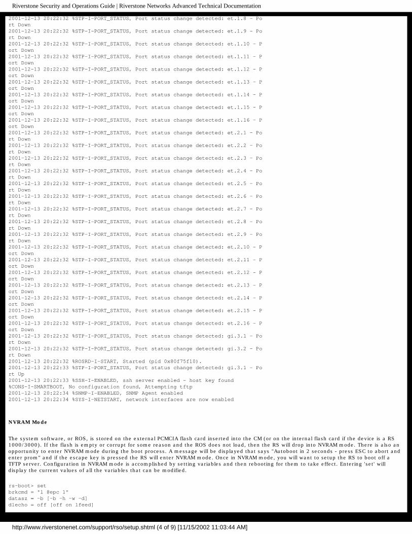
A normal boot sequence for an RS 3000 is shown below:
Boot Software Version prom-2.1.0.3, Built May 31 2000 16:51:30Processor: R7000 rev 2.1 [0x2721], 292 MHz, (bus: 83 MHz), 128 MB DRAMI-Cache 16 KB, linesize 32. D-Cache 16 KB, linesize 32.L2-Cache 256 KB, linesize 32, cache enabled.
Mounting 16MB flash card . . . DoneAutoboot in 2 seconds - press ESC to abort and enter prom
using link: bootsourcelink pointed at file:/pc-flash/boot/ros9101/source: file:/pc-flash/boot/ros9101/Loaded version fileLoading kernel (base 0x80001000, size 50528)
http://www.riverstonenet.com/support/rso/setup.shtml (2 of 9) [11/15/2002 11:03:44 AM]

Riverstone Security and Operations Guide | Riverstone Networks Advanced Technical Documentation
(base 0x8000d560, size 4894838)100% - Image checksum validated----------------------------------------------------------------------RS 3000 System Software, Version 9.1.0.1Copyright (c) 2000-2001, Riverstone Networks, Inc.Built by mhaydt@cmbuild0 on Mon Dec 10 16:33:02 2001Processor: R7000, Rev 2.1, 292 MHzSystem started on 2001-12-13 20:22:04----------------------------------------------------------------------2001-12-13 20:22:04 %SYS-I-FLASHCRD, Mounting 16MB Flash card2001-12-13 20:22:14 %SYS-I-FLASHMNTD, 16MB Flash card mounted2001-12-13 20:22:16 %SYS-I-INITSYS, initializing system RS 30002001-12-13 20:22:16 %SYS-I-DSCVMOD, discovered 'Control Module' module in slot CM2001-12-13 20:22:17 %SYS-I-INITSLOTS, Initializing system slots - please wait2001-12-13 20:22:27 %SYS-I-MODPROBE, Detecting installed media modules - pleasewait2001-12-13 20:22:27 %SYS-I-DSCVMOD, discovered '16-10/100-TX "T"' module in slot12001-12-13 20:22:27 %SYS-I-DSCVMOD, discovered '16-10/100-TX "T"' module in slot22001-12-13 20:22:27 %SYS-I-DSCVMOD, discovered '2-Gigabit-SX "T"' module in slot32001-12-13 20:22:29 %SYS-I-INITPORT, initialized slot 1, port 12001-12-13 20:22:29 %SYS-I-INITPORT, initialized slot 1, port 22001-12-13 20:22:29 %SYS-I-INITPORT, initialized slot 1, port 32001-12-13 20:22:29 %SYS-I-INITPORT, initialized slot 1, port 42001-12-13 20:22:29 %SYS-I-INITPORT, initialized slot 1, port 52001-12-13 20:22:29 %SYS-I-INITPORT, initialized slot 1, port 62001-12-13 20:22:29 %SYS-I-INITPORT, initialized slot 1, port 72001-12-13 20:22:29 %SYS-I-INITPORT, initialized slot 1, port 82001-12-13 20:22:29 %SYS-I-INITPORT, initialized slot 1, port 92001-12-13 20:22:29 %SYS-I-INITPORT, initialized slot 1, port 102001-12-13 20:22:29 %SYS-I-INITPORT, initialized slot 1, port 112001-12-13 20:22:29 %SYS-I-INITPORT, initialized slot 1, port 122001-12-13 20:22:29 %SYS-I-INITPORT, initialized slot 1, port 132001-12-13 20:22:29 %SYS-I-INITPORT, initialized slot 1, port 142001-12-13 20:22:29 %SYS-I-INITPORT, initialized slot 1, port 152001-12-13 20:22:29 %SYS-I-INITPORT, initialized slot 1, port 162001-12-13 20:22:29 %SYS-I-INITPORT, initialized slot 2, port 12001-12-13 20:22:29 %SYS-I-INITPORT, initialized slot 2, port 22001-12-13 20:22:29 %SYS-I-INITPORT, initialized slot 2, port 32001-12-13 20:22:29 %SYS-I-INITPORT, initialized slot 2, port 42001-12-13 20:22:29 %SYS-I-INITPORT, initialized slot 2, port 52001-12-13 20:22:29 %SYS-I-INITPORT, initialized slot 2, port 62001-12-13 20:22:29 %SYS-I-INITPORT, initialized slot 2, port 72001-12-13 20:22:29 %SYS-I-INITPORT, initialized slot 2, port 82001-12-13 20:22:29 %SYS-I-INITPORT, initialized slot 2, port 92001-12-13 20:22:29 %SYS-I-INITPORT, initialized slot 2, port 102001-12-13 20:22:29 %SYS-I-INITPORT, initialized slot 2, port 112001-12-13 20:22:29 %SYS-I-INITPORT, initialized slot 2, port 122001-12-13 20:22:29 %SYS-I-INITPORT, initialized slot 2, port 132001-12-13 20:22:29 %SYS-I-INITPORT, initialized slot 2, port 142001-12-13 20:22:29 %SYS-I-INITPORT, initialized slot 2, port 152001-12-13 20:22:29 %SYS-I-INITPORT, initialized slot 2, port 162001-12-13 20:22:30 %SYS-I-INITPORT, initialized slot 3, port 12001-12-13 20:22:30 %SYS-I-INITPORT, initialized slot 3, port 22001-12-13 20:22:31 %VLAN-I-ADDSUCCESS, 34 ports et.1.(1-16),et.2.(1-16),gi.3.(1-2) successfully added to VLAN DEFAULT2001-12-13 20:22:31 %SYS-I-PWROKAY, power supply in slot PS1 is operational2001-12-13 20:22:31 %SYS-I-NOPWRSPLY, power supply in slot PS2 not present or not turned on2001-12-13 20:22:31 %SYS-I-TEMPOKAY, system temperature is within operating parameters2001-12-13 20:22:31 %STP-I-PORT_STATUS, Port status change detected: et.1.1 - Port Down2001-12-13 20:22:31 %STP-I-PORT_STATUS, Port status change detected: et.1.2 - Port Down2001-12-13 20:22:31 %STP-I-PORT_STATUS, Port status change detected: et.1.3 - Port Down2001-12-13 20:22:31 %STP-I-PORT_STATUS, Port status change detected: et.1.4 - Port Down2001-12-13 20:22:32 %STP-I-PORT_STATUS, Port status change detected: et.1.5 - Port Down2001-12-13 20:22:32 %STP-I-PORT_STATUS, Port status change detected: et.1.6 - Port Down2001-12-13 20:22:32 %STP-I-PORT_STATUS, Port status change detected: et.1.7 - Port Down
http://www.riverstonenet.com/support/rso/setup.shtml (3 of 9) [11/15/2002 11:03:44 AM]
Riverstone Security and Operations Guide | Riverstone Networks Advanced Technical Documentation
2001-12-13 20:22:32 %STP-I-PORT_STATUS, Port status change detected: et.1.8 - Port Down2001-12-13 20:22:32 %STP-I-PORT_STATUS, Port status change detected: et.1.9 - Port Down2001-12-13 20:22:32 %STP-I-PORT_STATUS, Port status change detected: et.1.10 - Port Down2001-12-13 20:22:32 %STP-I-PORT_STATUS, Port status change detected: et.1.11 - Port Down2001-12-13 20:22:32 %STP-I-PORT_STATUS, Port status change detected: et.1.12 - Port Down2001-12-13 20:22:32 %STP-I-PORT_STATUS, Port status change detected: et.1.13 - Port Down2001-12-13 20:22:32 %STP-I-PORT_STATUS, Port status change detected: et.1.14 - Port Down2001-12-13 20:22:32 %STP-I-PORT_STATUS, Port status change detected: et.1.15 - Port Down2001-12-13 20:22:32 %STP-I-PORT_STATUS, Port status change detected: et.1.16 - Port Down2001-12-13 20:22:32 %STP-I-PORT_STATUS, Port status change detected: et.2.1 - Port Down2001-12-13 20:22:32 %STP-I-PORT_STATUS, Port status change detected: et.2.2 - Port Down2001-12-13 20:22:32 %STP-I-PORT_STATUS, Port status change detected: et.2.3 - Port Down2001-12-13 20:22:32 %STP-I-PORT_STATUS, Port status change detected: et.2.4 - Port Down2001-12-13 20:22:32 %STP-I-PORT_STATUS, Port status change detected: et.2.5 - Port Down2001-12-13 20:22:32 %STP-I-PORT_STATUS, Port status change detected: et.2.6 - Port Down2001-12-13 20:22:32 %STP-I-PORT_STATUS, Port status change detected: et.2.7 - Port Down2001-12-13 20:22:32 %STP-I-PORT_STATUS, Port status change detected: et.2.8 - Port Down2001-12-13 20:22:32 %STP-I-PORT_STATUS, Port status change detected: et.2.9 - Port Down2001-12-13 20:22:32 %STP-I-PORT_STATUS, Port status change detected: et.2.10 - Port Down2001-12-13 20:22:32 %STP-I-PORT_STATUS, Port status change detected: et.2.11 - Port Down2001-12-13 20:22:32 %STP-I-PORT_STATUS, Port status change detected: et.2.12 - Port Down2001-12-13 20:22:32 %STP-I-PORT_STATUS, Port status change detected: et.2.13 - Port Down2001-12-13 20:22:32 %STP-I-PORT_STATUS, Port status change detected: et.2.14 - Port Down2001-12-13 20:22:32 %STP-I-PORT_STATUS, Port status change detected: et.2.15 - Port Down2001-12-13 20:22:32 %STP-I-PORT_STATUS, Port status change detected: et.2.16 - Port Down2001-12-13 20:22:32 %STP-I-PORT_STATUS, Port status change detected: gi.3.1 - Port Down2001-12-13 20:22:32 %STP-I-PORT_STATUS, Port status change detected: gi.3.2 - Port Down2001-12-13 20:22:32 %ROSRD-I-START, Started (pid 0x80f75f10).2001-12-13 20:22:33 %STP-I-PORT_STATUS, Port status change detected: gi.3.1 - Port Up2001-12-13 20:22:33 %SSH-I-ENABLED, ssh server enabled - host key found%CONS-I-SMARTBOOT, No configuration found, Attempting tftp2001-12-13 20:22:34 %SNMP-I-ENABLED, SNMP Agent enabled2001-12-13 20:22:34 %SYS-I-NETSTART, network interfaces are now enabled
NVRAM Mode
The system software, or ROS, is stored on the external PCMCIA flash card inserted into the CM (or on the internal flash card if the device is a RS 1000/3000). If the flash is empty or corrupt for some reason and the ROS does not load, then the RS will drop into NVRAM mode. There is also an opportunity to enter NVRAM mode during the boot process. A message will be displayed that says "Autoboot in 2 seconds - press ESC to abort and enter prom" and if the escape key is pressed the RS will enter NVRAM mode. Once in NVRAM mode, you will want to setup the RS to boot off a TFTP server. Configuration in NVRAM mode is accomplished by setting variables and then rebooting for them to take effect. Entering 'set' will display the current values of all the variables that can be modified.
rs-boot> setbrkcmd = "l @epc 1"datasz = -b [-b -h -w -d]dlecho = off [off on lfeed]
http://www.riverstonenet.com/support/rso/setup.shtml (4 of 9) [11/15/2002 11:03:44 AM]

Riverstone Security and Operations Guide | Riverstone Networks Advanced Technical Documentation
dlproto = EtxAck [none XonXoff EtxAck]nameserver = 0.0.0.0localdomain = (unknown).comgateway = 0.0.0.0crashaction = reboot [reboot debug]hostport = tty1inalpha = hex [hex symbol]inbase = 16 [auto 8 10 16]moresz = 24prompt = "rs-boot> "regstyle = sw [hw sw]regsize = 32 [32 64]rptcmd = trace [off on trace]trabort = ^Kulcr = lf [cr lf crlf]uleof = %validpc = "_ftext etext"tty1 = 9600bootdiagmode = off [off on quick mfg-test]diag_log =mfg_loop_by = time [time count]bootdelay = 2promsetaddrs = 1mfg_loop_max = 7000autoboot = bootbootcount = 9CiscoCLI = 0tty0 = 38400netaddr = 0.0.0.0netmask = 255.255.255.0bootaddr = 0.0.0.0bootsource = link:/pc-flash/boot/bootsourceethaddr = 00:02:85:06:7f:80sysid = 1
Booting Off a TFTP Server
The key variables that we are concerned with to get us operational are as follows:
netaddr = 0.0.0.0netmask = 255.255.255.0bootaddr = 0.0.0.0bootsource = link:/pc-flash/boot/bootsource
The netaddr/netmask variables will configure the management, or en0 port, which is located on the CM. You need to connect that port to a network that has a TFTP server available, or directly into a machine that does, such as a laptop. In our example, we are plugging the en0 port into another switch to access a TFTP server sitting elsewhere on the network. If you are connecting, via Ethernet, directly into a machine running TFTP service, then setting the gateway variable is not required. It is required that the netaddr be set to an IP address in the same subnet as the machine your connected to though.
The example below shows the required variables being set and a successful boot-up from a TFTP server.
rs-boot> set netaddr 192.168.2.5rs-boot> set netmask 255.255.255.0rs-boot> set bootaddr 192.168.5.113rs-boot> set bootsource ros80011rs-boot> rebootRebooting. . .
Boot Software Version prom-2.1.0.3, Built May 31 2000 16:51:30Processor: R7000 rev 2.1 [0x2721], 292 MHz, (bus: 83 MHz), 128 MB DRAMI-Cache 16 KB, linesize 32. D-Cache 16 KB, linesize 32.L2-Cache 256 KB, linesize 32, cache enabled.
Mounting 16MB flash card . . . DoneAutoboot in 2 seconds - press ESC to abort and enter prom
source: tftp://192.168.5.113/ros9101File: version (872 bytes)Build location: host 'cmbuild0' by 'mhaydt'
http://www.riverstonenet.com/support/rso/setup.shtml (5 of 9) [11/15/2002 11:03:44 AM]

Riverstone Security and Operations Guide | Riverstone Networks Advanced Technical Documentation
Version: 9.1.0.1Build date: Mon Dec 10 16:33:02 2001File: kernel (4956121 bytes)Loading kernel (base 0x80001000, memsize 50528, filesize 33472)(base 0x8000d560, memsize 4894838, filesize 4894838)100% - kernel loadedFile: images/File: images/ssr_atm (926944 bytes)File: images/ssr_cmhe (784464 bytes)File: images/ssr_wan (1399552 bytes)File: images/ssr_atm155_sar (56192 bytes)File: images/ssr_atm155_fpga_400 (318257 bytes)File: images/ssr_atm155_fpga_800 (589453 bytes)File: images/pos_aps (20356 bytes)File: images/ssr_mpls_dp_tmac (823440 bytes)File: images/ssr_mpls_mc_tmac (495204 bytes)File: images/ssr_atm622_amac (450996 bytes)File: images/ssr_atm622_sar_rcv (174907 bytes)File: images/ssr_atm622_sar_xmt (271037 bytes)File: images/ssr_atm622_sar_diag (52152 bytes)Image checksum validated----------------------------------------------------------------------RS 3000 System Software, Version 9.1.0.1Copyright (c) 2000-2001, Riverstone Networks, Inc.Built by mhaydt@cmbuild0 on Mon Dec 10 16:33:02 2001Processor: R7000, Rev 2.1, 292 MHzSystem started on 2001-12-13 14:08:23
After the RS boots up, you will want to load the ROS software onto the flash. The procedure to do this is documented at the end of this chapter.
Setting System Passwords
Now that the RS is booted up, the first step is to set the system passwords. By default you can telnet, ssh and console into the RS without passwords. There are three different passwords that can be set on the RS: login, enable and diag. The login password is used for console, telnet and ssh access to the router. It is advisable that passwords be set for each level. Passwords need to be sufficiently long and obscure that they cannot be easily guessed and it is best for them to not be words or common slang that would appear in a dictionary. Avoiding common "hacker" phrases and mathematical constants is also advised. It is further recommended that passwords include capital letters, numbers and punctuation. All punctuation can be used in passwords except for the double quote (") and the question mark (?), as these characters are interpreted by the CLI.
Each respective password can be set using the command:
rs(config)# system set password [login|enable|diag] <password>
Configuring the Management Port (en0)
The management port, or en0, is the 10/100 TX port on the CM next to the console DB-9 connector. It acts like an ethernet NIC, and does not have ASICs to route traffic. All traffic that is passed through the management port is handled by the CPU, so you will want to keep its use limited to network management functions. The en0 port also cannot be routed. This means that routing protocols running on the RS will ignore it. To configure this port you would use the command:
rs(config)# interface add ip en0 address-netmask <ip-address/netmask>
Since en0 is a management port, it is recommended that ACLs be applied to it to limit access to all except for monitoring stations. An example of this is displayed below using 172.16.1.10 as the monitoring station:
rs(config)# acl en0-filter permit ip 172.16.1.10rs(config)# acl en0-filter deny any anyrs(config)# acl en0-filter apply interface en0 input
Choosing System Code (ROS)
Now that you have your management port configured, we can consider what ROS is running on the RS. The command:
RS# system show version
Will show the version as indicated in the output below:
http://www.riverstonenet.com/support/rso/setup.shtml (6 of 9) [11/15/2002 11:03:44 AM]

Riverstone Security and Operations Guide | Riverstone Networks Advanced Technical Documentation
Software InformationSoftware Version : 8.0.0.11 ßCopyright : Copyright (c) 2000-2001 Riverstone Networks, IncImage Information : Version 8.0.0.11, built on Mon Dec 10 16:33:02 Image Boot Location: slot0:boot/ros80011/Boot Prom Version : prom-2.0.0.0
Even though choosing a software version for the RS is much easier then many comparable devices in the field, it is still extremely important to test and certify a version for use within your network. Even though ROS software is thoroughly tested before it is released, it does contain thousands of features. It is impossible to test every feature in every scenario and every combination.
To properly test a version of code, a thorough test plan should be written up that details each of the features that will be utilized and a lab scenario should be setup as close to true operating conditions as possible. If a bug is found while working through the test plan, the impact of the bug should be measured against the requirements of the device and determined whether the specific version of code is suitable for deployment on your network. Then a ticket should be opened with the RTAC and the bug should be tracked until it can be fixed in a future release of code. Once a bug is found it should always remain a part of the test plan to ensure that it doesn't creep into a future version. The testing phase cannot be stressed enough as the result of an unstable router in a production environment can be very painful.
Code can be obtained, with a support contract, from the web address http://www.riverstonenet.com/support/support_sw_download.shtml
Upgrading the ROS
After selecting the version of code that is going to work best in your environment you will need to load it onto a TFTP server residing somewhere on the network. TFTP is a very insecure protocol and it is advised that access to it be heavily restricted or even when you're not using the service that it is shut down on the server in which it's running.
Before you load code onto the flash card, you need to determine if you have enough space to do so. The command:
rs# file dir slot0:
displays the amount of free space on the flash card in slot0: (use slot1: if that's where your flash card is inserted).
The output below shows that about 40% of the 16Mb flash card is utilized currently by the number of 512k blocks in use. This means there is just less then 10Mb free on the flash card.
Version: 2 Blocks total: 32004, used: 12959d--------- 0 0 1 2001-02-26 17:10:50 ./drwxrwxrwx 0 0 1 2001-02-26 17:12:45 boot/
If there is not room on the flash card for a second flash, and you aren't using a secondary flash card in your CM, then you will need to delete the image to make room for the new one. You can get a list of images with the command:
rs# system image list
Images currently available on Master CMslot0: ros8003L (version 8.0.0.3 L) [selected for next boot]
The output shows us there is a single image on the flash called 'ros8003L'. It also tells us that the image is selected for next boot. To free up space you are going to need to delete this image. The system will not allow you to delete a chosen image so you must first choose 'none' for the next boot.
rs# system image choose none
Choosing image on Primary CM%SYS-I-CHS_NONE_OK, no image chosen for reboot
Now you are able to delete the image:
rs# system image delete ros8003L
Deleting image from Primary CMImage ros8003L (version 8.0.0.3 L)Are you sure you want to remove this image [no]? yesRemoving image (takes a while) . . .kernel: 100%Image removed.
http://www.riverstonenet.com/support/rso/setup.shtml (7 of 9) [11/15/2002 11:03:44 AM]

Riverstone Security and Operations Guide | Riverstone Networks Advanced Technical Documentation
Now you can see the flash card has plenty of free space for the new image:
rs# file dir slot0:Version: 2 Blocks total: 32004, used: 12d--------- 0 0 1 2001-02-26 17:10:50 ./drwxrwxrwx 0 0 0 2001-02-26 17:12:45 boot/
Now to load the new image you will use the command:
rs# system image add 192.168.5.113 ros9101Downloading image 'ros9101' from host '192.168.5.113'download: done
Adding Image (Primary CM)to local image ros9101 (takes a while) . . .save:kernel: 100%images/ssr_atm: 100%images/ssr_cmhe: 100%images/ssr_wan: 100%images/ssr_atm155_sar: 100%images/ssr_atm155_fpga_400: 100%images/ssr_atm155_fpga_800: 100%images/ssr_mpls_dp_tmac: 100%images/ssr_mpls_mc_tmac: 100%images/ssr_atm622_amac: 100%images/ssr_atm622_sar_rcv: 100%images/ssr_atm622_sar_xmt: 100%images/ssr_atm622_sar_diag: 100%doneImage checksum validated.%SYS-I-BOOTADDED, Image 'ros9101' added.
rs# system image choose ros9101Choosing image on Primary CMMaking image ros9101 (version 9.1.0.1) the active imagefor next reboot . . .%SYS-I-CHS_OK, image successfully chosen
If you have two CMs installed, then the backup will automatically be upgraded when you update the primary. After you are done loading the code, you can reboot the RS to start operation with the new code.
Configuring the Loopback Interface
The loopback interface on a router is a logical interface that never goes down. It's also a single IP address that essentially acts as the identity of the router and can be reached via all physical interfaces. As you setup more services you will see that the loopback interface plays many roles in many different services. By default, the RS already comes with the loopback interface of 127.0.0.1, however in order to use the loopback interface to access the router or for different services, you must add another, routable IP address to it. To add additional loopback addresses you would use the command:
rs(config)# interface add ip lo0 address-network <ip-address>
<=Previous RSO Home Next =>
http://www.riverstonenet.com/support/rso/setup.shtml (8 of 9) [11/15/2002 11:03:44 AM]

Riverstone Security and Operations Guide | Riverstone Networks Advanced Technical Documentation
© 2001-2002, Riverstone Networks, Inc. All rights reserved. Privacy Statement Terms of Use Feedback
http://www.riverstonenet.com/support/rso/setup.shtml (9 of 9) [11/15/2002 11:03:44 AM]

Riverstone Security and Operations Guide | Riverstone Networks Advanced Technical Documentation
Support Home | Documentation Home |
<=Previous RSO Home Next =>
Setting Up Secure Services
Secure Access to the Router
Once a router is in operation, you need to ensure that you can access it securely. There are several different ways to access the router including telnet, SSH and the console. Also, there are a couple of protocols for external authentication. This chapter will discuss how to secure those services.
Telnet
Telnet (RFC 854) is a protocol that enables remote access to the CLI. Telnet is enabled by default on port 23. Use of telnet is being reduced where possible on the Internet because the content stream can be "sniffed" by an unauthorized party. The content of the telnet session includes the username and password that would compromise the sovereignty of the router if obtained by an unauthorized party. Access to the telnet port (23) can be restricted by IP source IP address, but since IP spoofing is possible, the best defense is to either use telnet only on a secure private network, or not use it at all. SSH is the alternative and is discussed below.
You can monitor your telnet server via the following commands:
rs# system show usersrs# system show telnet-access
To restrict access to the telnet server, you can create and apply a service ACL. In the example an ACL, called 'restrict-telnet', is created which allows the local network of 192.168.1.0/24 and then the ACL is applied to the telnet service. This ACL effectively blocks all traffic to port 23 that is not from the 192.168.1.0/24 network and logs the denied packets.
rs(config)# acl restrict-telnet permit ip 192.168.1.0/24rs(config)# acl restrict-telnet apply service telnet logging deny-only
To turn off the telnet server all together in favor of the SSH server, you should use the command to turn the SSH server on first:
rs# ssh server generate-key rsa
Then turn off the telnet server with the command:
rs(config)# system disable telnet-server
While on the router you can telnet to another host or router by using the telnet command:
rs# telnet <hostname>
SSH
SSH stands for Secure Shell and provides telnet-like access to the RS CLI. SSH is a preferred alternative to telnet since the session is encrypted. SSH will first ensure that its connecting to the correct device by comparing its public host key to a list stored locally. This ensures that there is not a device in the middle of the conversation passing along traffic between the two speakers transparently. To continue the server connection, the client then encrypts a random number using both the public host and server keys and sends the encrypted number to the SSH server. Both the SSH server and client will use this random number as a key to encrypt communications in their session.
http://www.riverstonenet.com/support/rso/secure_access.shtml (1 of 17) [11/15/2002 11:03:49 AM]

Riverstone Security and Operations Guide | Riverstone Networks Advanced Technical Documentation
The important detail that SSH brings is that the session is encrypted before a username or password is transferred across the wire. Riverstone currently implements SSH v1.5. SCP, which stands for secure copy, is also slated for a future release. SCP allows you to securely copy files, such as the router configuration, by encrypting them.You can monitor your SSH server via the following commands:
rs# system show usersrs# system show ssh-access
To restrict access to the SSH server, you can create and apply a service ACL. In the example an ACL, called 'restrict-ssh', is created which allows the local network of 192.168.1.0/24 and then the ACL is applied to the SSH service. This ACL effectively blocks all traffic to port 22 that is not from the 192.168.1.0/24 network and logs the denied packets.
rs(config)# acl restrict-ssh permit ip 192.168.1.0/24rs(config)# acl restrict-ssh apply service ssh logging deny-only
There are several ways to access a router via SSH. From a Unix machine you can use:A product from SSH Communications Security - http://www.ssh.comor a free variant such as OpenSSH - http://www.openssh.com/And from Windows there are several products available including:SecureCRT from Van Dyke Technologies, Inc - http://www.vandyke.com/or a free variant such as Teraterm - http://www.zip.com.au/~roca/ttssh.html
While on the router you can SSH to another host or router by using the slogin command:
rs# slogin <user@hostname>
Securing the Console
The first step to securing the console is to physically restrict access to it. As mentioned earlier, if a persona non grata can access your console port, they can just as easily cycle the power on the RS and perform a password recovery procedure. The console password is set automatically when you enable the login password:
rs(config)# system set password login <password>
Authenticating with RADIUS
RADIUS (Remote Authentication Dial In User Service) is a client-server protocol used for managing access to your routers most recently specified in RFC 2865 and RFC 2866. RADIUS originally started out as a way to authenticate dialup modem users (thus the name), but since has grown into a full-blown, standards-based protocol for authentication and accounting for any sort of remote access. RADIUS was developed completely within the IETF and is fully open and standards based. The next major revision of authentication and accounting protocols, Diameter, is also based on RADIUS.
Setting the Server
The first step to using RADIUS on your network is to setup a RADIUS server. Several examples for different RADIUS servers are given later on. The next step is to specify the server IP address, and if possible, backup server IP address on the router. The command to set the servers is:
rs(config)# radius set server <server-ip> rs(config)# radius set server <server2-ip>
Using centralized authentication servers is an important step in building a scalable infrastructure for controlling access to your routers. RADIUS is a UDP based protocol for a couple of different reasons. RADIUS is built for resiliency and speed. This means that a router isn't going to wait around for a failed RADIUS server and will quickly move to retransmit the authentication request to a backup server. Otherwise, you could be waiting several minutes for a RADIUS server to timeout using TCP's built in timers. RADIUS also doesn't require the overhead of TCP for handshakes and acknowledgements.
Setting the timeout
This also means that several timers have to be built into the RADIUS protocol itself. In ROS you can configure two different timers both at a global and server level. The first timer is the server timeout. This can be specified globally with the command:
rs(config)# radius set timeout <1-30>
http://www.riverstonenet.com/support/rso/secure_access.shtml (2 of 17) [11/15/2002 11:03:49 AM]

Riverstone Security and Operations Guide | Riverstone Networks Advanced Technical Documentation
The default is 10 seconds. Usually this is a comfortable number unless there is latency between the router and the RADIUS server in which the timeout value may need to be increased. The timeout can also be specified per server using the command:
rs(config)# radius set server <server-ip> timeout <1-30>
The server level command has a higher priority then the global command for the particular server that it is specified for. This means that you can set the global level commands that will apply to your servers, but if you need to change a setting for a specific server down the road, you can do so without disrupting your configuration for the other servers. The maximum number of RADIUS servers that can be specified is four.
Setting the Deadtime
Another timer you can specify is the 'deadtime' period. This is the number of minutes a server should be ignored after it has failed. The default deadtime setting is zero. This means that if your primary server fails, the router fails over to the secondary server, and the secondary fails, it will immediately retry the primary again. This default setting is most appropriate for a dual server setup. If the primary server fails and it fails over the secondary, and then the secondary fails, it can only try the primary again, which may or may not be back in service. Either way you have nothing to gain by ignoring one of the servers. The deadtime period is set at a global level using the command:
rs(config)# radius set deadtime <0-1440>
And set at a per server level using the command:
rs(config)# radius set server <server-ip> deadtime <0-1440>
The deadtime option becomes more useful when you have more then two servers and perhaps one is less reliable then the others or perhaps is being used for other services which are more important then RADIUS. This way if the server times out because its busy rather then outright failure, then it can be ignored for a period of time. A server can be ignored for up to 24 hours.
Setting the Retries
Another option that comes into play when considering a scenario where a server is not responding is the number of times the router will retry the authentication. Since the protocol is UDP, there isn't an acknowledgement for packets and the router will have no way of knowing if the packet reached the RADIUS server. The default number of times the RS will retry a server is three times. This is fine for most cases. The retry number is set globally using the command:
rs(config)# radius set retries <1-10>
And per server using:
rs(config)# radius set server <server-ip> retries <1-10>
Locking it Down
The RADIUS key is a string that is shared between the router and the RADIUS server. It can be up to 128 characters long and is encrypted as it travels between the router and the RADIUS server. The RADIUS server uses a combination of the key and the source IP address the packet came from to verify the packet came from a legitimate network device. Since the source IP address is easily spoofed, it becomes even more important to ensure that the key is sufficiently complex and cannot be easily guessed. Like other commands the key can be defined globally or on a per server basis using the commands:
rs(config)# radius set key <key>
and:
rs(config)# radius set server <server-ip> key <key>
As mentioned earlier, the RADIUS server also takes the source IP address into account when it receives and authentication request. Because of this there is an option to specify the source IP address you would like all packets to originate from. This is also useful when considering the accounting aspect of RADIUS since the logs generated will all have the source IP address (or hostname the IP address is mapped to) listed in the log file. It is recommended that the source IP address option be set to the loopback address of the router also. The command that will originate all packets to all of the RADIUS servers from a specific source IP address is:
rs(config)# radius set source <loopback-ip>
And if there is a specific RADIUS server that needs to view refer to the router using a different IP address, the specific source IP address sent to
http://www.riverstonenet.com/support/rso/secure_access.shtml (3 of 17) [11/15/2002 11:03:49 AM]

Riverstone Security and Operations Guide | Riverstone Networks Advanced Technical Documentation
that server can be set using:
rs(config)# radius set server <server-ip> source <source-ip>
There are commercial RADIUS servers, such as SecurID that support one time passwords that are generated at a regular interval, such as 60 seconds, and based on a random source. This can provide an extremely effective defense against password attacks. The question of whether you need to add this layer of security is an exercise left to the reader.
Setting the Ports
The default RADIUS ports used by the router and defined in RFC 2865 and RFC 2866, are 1812 for RADIUS authentication and 1813 for RADIUS accounting. Originally they were defined as ports 1645 and 1646 respectively, but they conflicted with other ports which were defined earlier with the Internet Assigned Numbers Authority (IANA). Some RADIUS server implementations may use the older ports as a default, so you will want to ensure that the ports with your RADIUS server match the defaults of the device making the authentication requests, or change the ports on the device. This can only be done on a per server level not globally using the command:
rs(config)# radius set server <server ip> auth-port <port> acct-port <port>
Activating RADIUS
RADIUS can be enabled for the initial logging into the router as well as for enable mode. To enable RADIUS for the initial login, use the command:
rs(config)# radius authentication login
And to enable RADIUS authentication for enable mode use the command:
rs(config)# radius authentication enable
The final, but very important option you want to set for RADIUS authentication is the last-resort. If the router cannot reach any RADIUS servers and the last-resort isn't set, you're not going to be logging into that router. Usually if the router cannot contact the RADIUS servers, there is something wrong with the network and it is going to be a really bad time to not be able to access your router. The last-resort option indicates what is supposed to happen when none of the RADIUS servers can be reached. It can be used to deny all requests, which is probably going to be the case anyway, allow all requests, which isn't a very secure option, or to fall back on the respective system passwords set on the router. The latter is a good choice. This way you can always ensure that you will be able to access the router in a secure method even if the RADIUS servers cannot be reached. Set the last-resort option with the command:
rs(config)# radius set last-resort password
Make sure that your passwords are properly set also using the commands:
rs(config)# system set password login <password>rs(config)# system set password enable <password>
Finally, RADIUS authentication is activated using the command:
rs(config)# radius enable
You will want to make sure that you have all of your options set (especially your last-resort) and your RADIUS server(s) reachable before you enable RADIUS. Its also advisable that if you are enabling RADIUS remotely that you leave an enabled session open to the router and use another session to verify that it is functioning properly before logging out.
Using RADIUS Accounting
The accounting part of the RADIUS protocol is defined in RFC 2866. In the context of routers, (as opposed to modems) accounting is used to keep track of the commands entered. The commands are usually logged to a separate detail file for each router into separate records. Each record includes the command typed, the date and time, the user that typed it, and the router it came from. In total this generates nine lines of log file for each command. There are many variations of the type of information which can be recorded via RADIUS accounting. The table below shows the command and describes the information that will be logged by each one.
radius accounting command level 5 Config mode commands are loggedradius accounting command level 10 Enable mode commands are loggedradius accounting command level 15 Exec Level commands are loggedradius accounting snmp active SNMP set to the active config are loggedradius accounting snmp startup SNMP set to the startup config are logged
http://www.riverstonenet.com/support/rso/secure_access.shtml (4 of 17) [11/15/2002 11:03:49 AM]

Riverstone Security and Operations Guide | Riverstone Networks Advanced Technical Documentation
radius accounting system info All messages are loggedradius accounting system warning Warning level messages are loggedradius accounting system error Error level messages are loggedradius accounting system fatal Fatal level messages are loggedradius accounting shell all Start and end of any event that starts a shell
After you determine the level of detail that you need to log for your routers you can pick commands ala Carte from the table above to suit your needs. For example, if you are very active on your routers you may just want to log the commands entered into config mode to make for manageable logs and you use SNMP to configure interfaces, so you log that activity also. A suggested command set that provides a middle ground of logging so you don't miss anything important, but shouldn't be overwhelming is below.
rs(config)# radius accounting command level 15rs(config)# radius accounting snmp activers(config)# radius accounting snmp startuprs(config)# radius accounting system warningrs(config)# radius accounting shell all
It is also suggested that the logs are parsed at a regular interval for key commands that could affect the network.
Setting up Cistron RADIUS
This config details the installation and setup of Cistron RADIUS, which is freely available at http://www.radius.cistron.nl/. This is the most accessible RADIUS server available today. The original Livingston server is now only available to Lucent customers, but is still widely used, so its installation is detailed below. A newer version of Cistron called FreeRADIUS is still in beta, and other servers such as Steel-belted RADIUS are commercial products. There are also alternatives such as the Cistron derivative ICRadius which uses MYSQL as a back-end, but these are outside the scope of this document. This installation and setup is performed on a Linux box, so some of the commands may use Linux specific flags, but the radius daemon should be platform independent.
Installing Cistron RADIUS
After downloading the archive from the website, installation should be painless. Unzip the archive and cd into the directory first:# gunzip -c radiusd-cistron-1.6-stable.tar.gz | tar xvf -# cd radiusd-cistron-1.6.4Then copy the 'Makefile' for your particular OS from the src directory.# cd src # ls# cp Makefile.OS Makefile
Then run makeWhen you run 'make install', the binaries are placed into /usr/local/bin and /etc/raddb is created for the configuration files. The noteworthy configuration files consist of:
Users Security and authentication information for each userNaslist Lists the routers, associates them to a nickname and defines the type of device they areClients Lists all of the routers and associates them to their respective encryption key
First lets setup our clients file. For our setup above, we will place the following into the clients file:
# Client Name Key#--------------------------10.0.0.1 secretkey
To setup the naslist file for the above setup we will place the following entry:
# NAS Name Short Name Type#---------------- ----------- --------10.0.0.1 secure-rs1 other
The user file is the most complex file of them all. There are numerous options available for authenticating users, with most of the options only being relevant to dial-up access. We will demonstrate three of the available options relevant to our setup, local passwords, local encrypted passwords and using the /etc/passwd. Unless using the users file for authentication elsewhere, you should ensure the existing configuration in the users file is commented out or deleted.
Local Password entries for users noc and admin, which uses clear-text passwords, an insecure option, this file should have very restrictive permissions:
http://www.riverstonenet.com/support/rso/secure_access.shtml (5 of 17) [11/15/2002 11:03:49 AM]

Riverstone Security and Operations Guide | Riverstone Networks Advanced Technical Documentation
noc Auth-Type = Local, Password = "secret1"admin Auth-Type = Local, Password = "secret2"
Authenticate off the /etc/passwd file where users are already stored, which doesn't leave any way to differentiate what users can log into the server which the passwd file is stored and what users can log into both the server and all of the routers that are authenticating from the server.
noc Auth-Type = Systemadmin Auth-Type = System
Local Encrypted Password entries for users noc and admin, which use encrypted passwords, which is the most secure option with the best control. Even though the passwords are encrypted, the can be cracked, so restrictive permissions are recommended:
noc Auth-Type = Crypt-Local, Password = "Mw5$6kt7pYWtx3s/4yw0.T6yG1"admin Auth-Type = Crypt-Local, Password = "Mtf$zbZpsriVnd5dKBNBAnd1U/"
After you make any change to the users file you must HUP radiusd to reread the file:
kill -1 `cat /var/run/radiusd.pid`
Running RADIUS
To start RADIUS, type /usr/local/bin/radiusd. Some of the available handy switches for RADIUS are:
● -a - Accounting directory: Within the accounting directory, radiusd will create a directory for each one of the routers and store its detail file for that router in that directory. Default is /var/log/radacct
● -l - Log directory: This is where the radius.log file is stored. Default is /var/log● -C - Checks the syntax of the config files● -y - Details each user's incorrect password attempt. Can be handy for troubleshooting fat fingers.● -z - Details each user's password, correct and incorrect. This is obviously a very insecure option.
Authenticating with TACACS+
TACACS (Terminal Access Controller Access Control System) is a legacy authentication protocol used to manage access to network devices. It started out its life in ARPANET and BBN and since then commercial development has taken over and TACACS is largely a proprietary protocol, but is included in this document since many networks have existing TACACS implementations. An informational RFC (RFC 1492) was released in 1993 to compensate for the lack of documentation and copyright constraints.
There have been several revisions of TACACS over the years starting with the original protocol specification known just as TACACS. It is an insecure and obsolete protocol that does not support encrypted communications or accounting. TACACS is supported in ROS, but not recommended for production use.
The next revision of the TACACS protocol was known as Extended TACACS, which was as the name implies, an extension to the original TACACS protocol. Extended TACACS supported encrypted communications using a key, and accounting. This revision is not supported in ROS. Extended TACACS is also not compatible with TACACS+.
The latest revision of TACACS is known as TACACS+. TACACS+ is a complete rewrite of the original protocol and is very similar to RADIUS. This revision supports authentication, encryption via a key, and accounting.
The setup, operation and commands of TACACS+ are very similar to RADIUS. You may want to skim or skip this chapter if you just read the RADIUS section and want to avoid the déjà vu of it all.
Setting the Server
To get the RS to start authenticating off an existing TACACS+ server, first the server must be specified. Setting a backup server is always a good idea of course. The maximum number of servers that can be set is five.
rs(config)# tacacs-plus set server <server-ip>rs(config)# tacacs-plus set server <server2-ip>
Setting the Timeout
http://www.riverstonenet.com/support/rso/secure_access.shtml (6 of 17) [11/15/2002 11:03:49 AM]

Riverstone Security and Operations Guide | Riverstone Networks Advanced Technical Documentation
The timeout setting specifies how long the RS should wait for the server to respond to the request. The default is 10 seconds. Usually this is a comfortable number unless there is latency between the router and the TACACS server in which the timeout value may need to be increased.
rs(config)# tacacs-plus set timeout <1-30>
The server level command has a higher priority then the global command for the particular server that it is specified for. This means that you can set the global level commands that will apply to your servers, but if you need to change a setting for a specific server down the road, you can do so without disrupting your configuration for the other servers.
rs(config)# tacacs-plus set server <server-ip> timeout <1-30>
Setting the Deadtime
Another timer you can specify is the 'deadtime' period. This is the number of minutes a server should be ignored after it has failed. The default deadtime setting is zero. This means that if your primary server fails, the router fails over to the secondary server, and the secondary fails, it will immediately retry the primary again. This default setting is most appropriate for a dual server setup. If the primary server fails and it fails over the secondary, and then the secondary fails, it can only try the primary again, which may or may not be back in service. Either way you have nothing to gain by ignoring one of the servers. The deadtime period is set at a global level using the command:
rs(config)# tacacs-plus set deadtime <0-1440>
And set at a per server level using the command:
rs(config)# tacacs-plus set server <server-ip> deadtime <0-1440>
You can ignore a server for up to 24 hours.
Setting the Retries
The retries value is the number of times the router will retry the authentication. Even though the protocol is TCP based, unless the 'single-connect' option is set, the RS will still make a connection for every request. The default number of times a server will be tried is three times.
rs(config)# tacacs-plus set retries <1-10>
And per server using:
rs(config)# tacacs-plus set server <server-ip> retries <1-10>
Locking it Down
The TACACS+ key is a string that is shared between the router and the TACACS+ server. It can be up to 128 characters long and is encrypted as it travels between the router and the TACACS+ server. The TACACS+ server uses a combination of the key and the source IP address the packet came from to verify the packet came from a legitimate network device. Since the source IP address is easily spoofed, it becomes even more important to ensure that the key is sufficiently complex and cannot be easily guessed. Like other commands the key can be defined globally or on a per server basis using the commands:
rs(config)# tacacs-plus set key <key>
and:
rs(config)# tacacs-plus set server <server-ip> key <key>
As mentioned earlier, the TACACS+ server also takes the source IP address into account when it receives and authentication request. Because of this, there is an option to specify the source IP address you would like all packets to originate from. This is also useful when considering the accounting aspect of TACACS+ since the logs generated will all have the source IP address (or hostname the IP address is mapped to) listed in the log file. It is recommended that the source IP address option be set to the loopback address of the router also. The command that will originate all packets to all of the TACACS+ servers from a specific source IP address is:
rs(config)# tacacs-plus set source <loopback-ip>
And if there is a specific TACACS+ server that needs to view refer to the router using a different IP address, the specific source IP address sent to that server can be set using:
http://www.riverstonenet.com/support/rso/secure_access.shtml (7 of 17) [11/15/2002 11:03:49 AM]

Riverstone Security and Operations Guide | Riverstone Networks Advanced Technical Documentation
rs(config)# tacacs-plus set server <server-ip> source <source-ip>
Setting the Ports
The default TACACS ports used by the router is 49. This can be changed on a per server level using the command:
rs(config)# tacacs-plus set server <server ip> auth-port <port> acct-port <port>
Activating TACACS+
TACACS+ can be enabled for the initial logging into the router as well as for enable mode. To enable TACACS+ for the initial login, use the command:
rs(config)# tacacs-plus authentication login
And to enable TACACS+ authentication for enable mode use the command:
rs(config)# tacacs-plus authentication enable
The final, but very important option you want to set for TACACS+ authentication is the last-resort. If the router cannot reach any TACACS+ servers and the last-resort isn't set, you're not going to be logging into that router. Usually if the router cannot contact the TACACS+ servers, there is something wrong with the network and it is going to be really bad time to not be able to access your router. The last-resort option indicates what is support to happen when none of the TACACS+ servers can be reached. It can be used to deny all requests, which is probably going to be the case anyway, allow all requests, which isn't a very secure option, or to fall back on the respective system passwords set on the router. The latter is a good choice. This way you can always ensure that you will be able to access the router in a secure method even if the TACACS+ servers cannot be reached. Set the last-resort option with the command:
rs(config)# tacacs-plus set last-resort password
Make sure that your passwords are properly set also using the commands:
rs(config)# system set password login <password>rs(config)# system set password enable <password>
Finally, TACACS+ authentication is activated using the command:
rs(config)# tacacs-plus enable
You will want to make sure that you have all of your options set (especially your last-resort) and your TACACS+ server(s) reachable before you enable TACACS+. Its also advisable that if you are enabling TACACS+ remotely that you leave an enabled session open to the router and use another session to verify that it is functioning properly before logging out.
Using TACACS+ Accounting
The table below shows the command and describes the information that will be logged by each one.
tacacs-plus accounting command level 5 Config mode commands are loggedtacacs-plus accounting command level 10 Enable mode commands are loggedtacacs-plus accounting command level 15 Exec Level commands are loggedtacacs-plus accounting snmp active SNMP set to the active config are loggedtacacs-plus accounting snmp startup SNMP set to the startup config are loggedtacacs-plus accounting system info All messages are loggedtacacs-plus accounting system warning Warning level messages are loggedtacacs-plus accounting system error Error level messages are loggedtacacs-plus accounting system fatal Fatal level messages are loggedtacacs-plus accounting shell all Start or end of any event that starts a shell
After you determine the level of detail that you need to log for your routers you can pick commands ala carte from the table above to suit your needs. For example, if you are very active on your routers you may just want to log the commands entered into config mode to make for manageable logs and you use SNMP to configure interfaces, so you log that activity also. A suggested command set that provides a middle ground of logging so you don't miss anything important, but shouldn't be overwhelming is below.
http://www.riverstonenet.com/support/rso/secure_access.shtml (8 of 17) [11/15/2002 11:03:49 AM]

Riverstone Security and Operations Guide | Riverstone Networks Advanced Technical Documentation
rs(config)# tacacs-plus accounting command level 15rs(config)# tacacs-plus accounting snmp activers(config)# tacacs-plus accounting snmp startuprs(config)# tacacs-plus accounting system warningrs(config)# tacacs-plus accounting shell all
It is also suggested that the logs are parsed at a regular interval for key commands that could affect the network.
NTP - Network Time Protocol
A question that has been asked since the early days of the Internet always has been "what time is it anyway?" Keeping time on a network has always been an objective and has produced a long history of time algorithms and protocols.
To find out more about the history and research side of NTP, check out the website of Dr. David Mills. Dr. Mills has been involved with the Internet since participating in DARPA contracts in the seventies and eighties and protocols he developed have evolved to NTP. http://www.eecis.udel.edu/~mills/
The importance of keeping accurate time on a network is often underestimated. It would not be possible to correlate events with accounting logs and perform any sort of meaningful security or incident analysis without correct and consistent time across all of your network devices.
For instance, let's say that you receive a subpoena from the State's Attorney's office, seeking information in a stalking investigation. All that is available is an IP address local to your network and a timestamp. After looking up the IP address, you realize that it belongs to an analog modem pool. Your next step is to correlate the IP address with the RADIUS logs from your modem pool. You search through the logs and find that no one was logged onto that IP address at that time. Perplexed you look into the situation a bit closer and realize that the time on the RADIUS server is off by years. All of your logs are now useless since you cannot differentiate between the 3542 users that have used that IP address during the month.
Having an accurate NTP infrastructure across your network can make all the difference.
There are currently four versions of NTP available. V1 and V2 are depreciated and not used any longer, V3 is the de facto standard on the Internet and V4 is the newest version still being developed. The RS platforms support versions V1, V2 and V3. V4 will be implemented in a future release. Since V1 and V2 are largely not used any longer, the remainder of this chapter will focus on NTP V3.
Building a NTP Infrastructure
The goal of NTP is not to synchronize all of the servers that are running the service to each other, but to set time as close to universal coordinated (UTC) as possible, or "true time" as it is sometimes called. The algorithms work best when the server has multiple time sources to compare time against and derive what it feels is closest to UTC. NTP works this way because inevitably a time source is going to have the wrong time. When this happens, the client is able to determine, through comparisons, that the time source has a bogus time and is able to compensate for that. Within the NTP protocol, there are many significant and complex algorithms to cope with many different situations including bogus time propagation and server failure.
However, when in a controlled environment, such as your own local network, there are times when you just want to know what time it is. To simplify this process, Simple Network Time Protocol (SNTP) was developed and is specified in RFC 1361. The NTP implementation found in ROS is based upon SNTP. This means that you will need to build a NTP infrastructure to provide time services down to your network clients.
NTP, like most things, scales best using a hierarchical design. Each level of the hierarchy is known as a stratum. At the top of the hierarchy are the stratum 1 time servers. These servers set their clock via some external means such as an atomic, radio or GPS clock. A stratum 1's clock is usually set within a few microseconds of "true time". The use of these servers is intended to act as a time source for stratum 2 servers that are servicing hundreds or thousands of clients. Clients should not contact stratum 1 servers directly as doing so does not scale and would have a negative impact on the stratum 1 servers.
Depending upon the size of your network, you will want at least two, if not three stratum 2 or 3 servers for your clients to synchronize to. If each of those servers have two external time sources each, and are setup in a peer configuration, then your network will have six external time sources to ensure an accurate time source for your clients. If you are running a very large network, you may want to invest in a GPS or radio clock (or two) and run your own stratum 1 servers. This will ensure the most accurate time available for your network.
Configuring the Time
Before you enable the NTP client on the RS, you should set the time and time zone that is appropriate. Even if your network extends across multiple time zones, it is recommended that you set all of the devices under your control to the same time zone to keep problem tracking and analysis simplified. Extending that recommendation it is recommended that you set all of your devices to the UTC time zone, also for reasons of simplicity. To set your time zone to UTC time use the command:
rs(config)# system set timezone utc
http://www.riverstonenet.com/support/rso/secure_access.shtml (9 of 17) [11/15/2002 11:03:49 AM]

Riverstone Security and Operations Guide | Riverstone Networks Advanced Technical Documentation
To set it to Eastern time use:
rs(config)# system set timezone est
Or if in Japan:
rs(config)# system set timezone utc+9
Dealing with daylight savings time may be an issue if your time zone supports it. The RS provides a wide variety of options to setup daylight savings time including by date or by a specific day of the month. The following command sets daylight savings time for EST and changes it to EDT in 2002.
rs(config)# system set dst-changing system set dst-changing s-mo 4 s-wk 2 s-dow 1 s-hr 2 s-min 0 e-mo 10 e-wk 5 e-dow 1 e-hr 2 e-min 0
Once you have determined your time zone and requirements as far as daylight savings time, go ahead and set the time and date on the RS using the command:
rs(config)# system set date year <year> month <month> day <day> hour <hour> min <min> second <sec>
Once your infrastructure is in place, you can enable NTP on your RS using the command:
rs(config)# ntp set server 192.168.2.2 version 3 source 10.0.0.1 interval 1
Configuring Secure Routing Services
Routing is the lifeblood of the Internet. Exchanging prefixes that reveal where networks are located and the best paths to those networks is what brings everything together. If the routing process is compromised, then the basic functionality of the entire network is at risk. This section will discuss some of the ways to preserve the integrity of network routing.
IGP Authentication
OSPF
As you scale your network, inevitably an IGP such as OSPF or IS-IS will be implemented to lessen the manual labor that go along with static routes or to scale past the limitations of RIP.
One of the ways to enforce security within your IGP is to implement passwords between the neighbors or peers. There are a couple of steps in this process.
First, you need to create a key chain:
rs(config)# ip-router authentication create key-chain <name> key <key-value> type <primary>|<secondary> id <MD5-integer>
The number or string is simply a way to identify the chain. The key is the shared value (much like a password) and can be up to 16 characters in length. The default type is primary, which is fine. The id is used when your using MD5 (as you should be).
Once the key chain is created you can associate it with your IGP, in this case OSPF:
rs(config)# ospf set area <area> authentication-method <auth-type> key-chain <chain-name>
This command ties the area to the key chain and indicates what type of authentication to use, your choices are simple and MD5. MD5 should always be used since simple is clear text and inherently insecure. This also specifies the authentication for the entire area. All OSPF neighbors need to have this same key configured to operate with each other.
You can also do this on a per interface basis with the command:
rs(config)# ospf set interface <int-name> key-chain <chain-name> authentication-method <auth-type>
IS-IS
http://www.riverstonenet.com/support/rso/secure_access.shtml (10 of 17) [11/15/2002 11:03:49 AM]

Riverstone Security and Operations Guide | Riverstone Networks Advanced Technical Documentation
To turn on authentication when using IS-IS, the procedure is essentially the same except for the protocol specific command. For IS-IS the command to tie the key chain to the protocol is:
rs(config)# isis set area-key-chain <chain-name> authentication-method <auth-type>
You can also set the authentication up at the domain level with the command:
rs(config)# isis set domain-key-chain <chain-name> authentication-method <auth-type>
As with OSPF, any device that you wish to trade routes with also needs the same key configured.
BGP Authentication
Keeping along the theme that is important to authenticate your routing peers and neighbors, BGP also supports authentication. You can set the password on a per group or per peer basis. The password is MD5 based and can have a length up to 80 characters. BGP authentication is documented in RFC 2385.
To set the password on a group basis use the command:
rs(config)# bgp set peer-group <group-name> password <password>
And to set the password on a per-peer basis use:
rs(config)# bgp set peer-host <peer-ip> password <password>
BGP Damping
BGP is a highly scalable inter-domain routing protocol that has done a nice job keeping the Internet running for some number of years. It works by keeping track of and exchanging route prefixes for all Internet connected networks. Whenever a route is added or removed, that change is propagated to the thousands of BGP routers on the Internet. Since there are many thousands of routes (105k-110k at last check), if there wasn't a measure of route status stability, the BGP routers would be overwhelmed with adding and removing routes. Many times, this is caused by a physical circuit bouncing up and down. This causes the route to be withdrawn and added back into the table every time until the router is thrashing to keep up. To prevent this from happening and allow BGP to scale, route damping was implemented so that troublesome routes could be ignored.
There are two aspects to route damping of concern. The first is making sure that your routers are not adversely affected by flapping routes. The second is to ensure that other routes are not adversely affected by your flapping routes and dampen those routes.
Damping Routes
By configuring a route damping policy, the provider will protect against upstream route flapping. By configuring a hold-timer, all upstream announcements can be delayed for a defined period to allow the route to be truly validated as stable prior to advertisement to the upstream peer. Route damping itself is described in RFC 2439 and implementation is described in RIPE-229.
The route flap damping mechanism within the RS platform is based on an instability metric based upon the number of times a route has flapped over a given period. To begin with, a route starts out with a value of zero. Every time a route flaps, its instability metric increases by one. By default when the metric value goes above three, the route is no longer advertised (thus dampened). The instability metric is however decaying over time. Every 15 minutes (900 seconds) the current instability metric is halved. Once the metric falls below two the route is advertised again.
By default, the instability metric can go no higher than a value of 16, which is equivalent to 60 minutes. The diagram shown below illustrates the damping implementation on the RS platform. The spikes represent route-flaps, which are then decaying over time. Each time a flap is incurred a penalty metric is enforced.
http://www.riverstonenet.com/support/rso/secure_access.shtml (11 of 17) [11/15/2002 11:03:49 AM]

Riverstone Security and Operations Guide | Riverstone Networks Advanced Technical Documentation
Figure 1: Damping Mechanism in Use
The graph shows the damping process being applied to three prefixes of different sizes:
192.168.60.0/24172.16.0.0/2210.0.40.0/19
The first prefix, 192.168.60.0/24, is shown in red. As you can see from the graph, it flapped four times, after 3 minutes, 6 minutes, 11 minutes and 17 minutes. Each time a flap occurred, the penalty increased by one. After it was greater then 3, the route was suppressed. After 30 minutes, the penalty reached the re-use limit and it was not ignored any further. The commands to enable this level of damping for /24 and longer prefixes are:
rs(config)# ip-router policy create filter dampenlongprefixes network all between 24-32
rs(config)# route-map dampen-long permit 5 match-prefix filter dampenlongprefixes
rs(config)# route-map dampen-long set dampenflap reach-decay 1800 unreach-decay 1800 suppress-above 3 reuse-below 2 max-flap 4 keep-history 7200 state enable
The second prefix, 172.16.0.0/22, is shown in green. The graph shows a slightly more tumultuous time for this prefix. At 19 minutes, it flapped once, and at 28 minutes, it flapped a second time. Then the half-life timer expired after 15 minutes so it made it out of the danger zone. Then it flapped again at 45 and nearly made it two-thirds of the way through its half-life timer. Then it flapped two more times at 55 and 57 minutes, which put its penalty over 3. Then the prefix was suppressed for 15 minutes until the 70-minute mark when the penalty was halved and it fell under the reuse of 2 so it was not ignored any further. To implement this level of damping for /22s and /23s use these commands:
rs(config)# ip-router policy create filter dampenmediumprefixes network all between 22-23
rs(config)# route-map dampen-med permit 5 match-prefix filter dampenmediumprefixes
rs(config)# route-map dampen-med set dampenflap reach-decay 900 unreach-decay 900 suppress-above 3 reuse-below 2 max-flap 4 keep-history 7200 state enable
The third prefix, 10.0.40.0/19, is show in blue. This prefix took three hits right in a row at minutes 10, 13 and 15. It was suppressed for 10 minutes until the penalty was halved which put it under the suppress limit and could be heard again. To enable this level of damping for /21 and shorter prefixes:
rs(config)# ip-router policy create filter dampenshortprefixes network all between 21-0
rs(config)# route-map dampen-short permit 5 match-prefix filter dampenshortprefixes
rs(config)# route-map dampen-short set dampenflap reach-decay 600 unreach-decay 600 suppress-above 3 reuse-below 2 max-flap 4 keep-history 3600 state enable
http://www.riverstonenet.com/support/rso/secure_access.shtml (12 of 17) [11/15/2002 11:03:49 AM]

Riverstone Security and Operations Guide | Riverstone Networks Advanced Technical Documentation
Once your damping is in place you can check the status of it with the command:
rs(config)# bgp show flap-statistics all
An example of the output is below. Routes that are not dampened, but have flapped will be proceeded with an 'h' for history and those that are currently being dampened are proceeded with a 'd'.
BGP table : Local router ID is 10.0.0.2Status codes: s suppressed, d damped, h history, * valid, > bestOrigin codes: i - IGP, e - EGP, ? - incomplete
Network Next Hop Metric Last-Flap Reuse Path ------- -------- ------ --------- ----- ---- *d 15/22 192.168.2.254 3.47 00:00:44 00:13:00 (2) 1 i *> 20/19 192.168.2.254 0.76 00:04:03 (2) 1 i
Holding Routes
Also to encourage stability of the BGP infrastructure it is a good idea to delay announcing your own routes until you can have some idea that they are stable. Suppressing the announcements for 60 seconds should be enough to ensure the announced prefixed aren't originating from a network on the other side of a violently flapping circuit. To delay the announcement by 60 seconds use:
rs(config)# bgp set peer-group out-delay 60
Or on at a host level (for external hosts only):
rs(config)# bgp set peer-host <ip-address> out-delay 60
If you are using the 'out-delay' option with IBGP/internal announcements, only apply it at the group level, not the host level.
Prefix Aggregation
Another way to contribute to the goal of BGP stability and help fight route table bloat is to aggregate your routes. There are few valid reasons for someone assigned a /19 of address space to announce it as 32 /24s. By announcing the aggregate, you are shielding the rest of the Internet from the ups and downs of your own network.
Nailing Up Announcements
You may also want to consider nailing up your announcements depending upon your topology. For instance, if you are multi-homed, and simply announcing a /19 down both circuits, then you could bind the announcement to the loopback so it was never withdrawn. Since the loopback won't ever be in a down state, the announcement will never be withdrawn. If one of the circuits goes down, then the announcement physically cannot be advertised via that provider any longer and will be withdrawn from the global routing table.
If the situation arises, where a subnet, of which you are announcing the aggregate, becomes unreachable within your network, this should be fine. Even though the subnet is unreachable or flapping, telling the rest of the Internet is not going to improve the situation since there isn't an alternate path for the traffic anyway. At worst, the case could be that you repair the circuit causing the network to flap and find that your downtime needs to persist for another few hours until the other routers stop damping your announcement. To nail up an announcement you can use the following commands:
rs(config)# ip add route 1.88.0.0/19 gateway 127.0.0.1 blackholers(config)# bgp advertise network 1.88.0.0/19
4.2.4 Access Control Lists (ACLs)
Next to physical access control, ACLs are fundamental building blocks in most well thought out security policies. The ability to control and monitor what enters and leaves your network is the definition of network security.
It is important to keep in mind that you use a router to move traffic, not to stop it. ACLs bring some firewall-like features to routers, but consider each situation carefully and make sure your using the right tool for the job.
Some of the well-known and accepted filtering practices found on the Internet today include:
http://www.riverstonenet.com/support/rso/secure_access.shtml (13 of 17) [11/15/2002 11:03:49 AM]

Riverstone Security and Operations Guide | Riverstone Networks Advanced Technical Documentation
● Ingress Filtering (RFC 2827/BCP 38)● Private Address Space Filtering (RFC 1918)● Bogon and Martian Filtering (draft-manning-dsua-08.txt)
Ingress Filtering
Ingress filtering as specified in RFC 2827/BCP 38 is highly recommended to not just secure your own network, but to ensure that other networks cannot be attacked from your network using spoofed source IP addresses. Many network attacks make use of spoofed source IP addresses to hide the identity of the attacked. If every network performed ingress filtering then attacks would be much easier to trace since the attacker would have to use a true source address. There won't ever be a time where all networks filter as they should, but you should do your part and encourage others to do the same.
If our address space that is assigned the network were 192.168.0.0/19, the commands to implement ingress filtering on our Internet connected interface would be:
rs(config)# acl ingress-filter permit ip 192.168.0.0/19 anyrs(config)# acl ingress-filter deny ip any any logrs(config)# acl ingress-filter apply interface <ip-int> output
Filtering Unallocated IP Space
IP space is allocated by the Internet Assigned Numbers Authority to the regional internet registries (RIRs). The top level RIRs are:
ARIN - American Registry for Internet Numbers (http://www.arin.net)RIPE - Re´seaux IP Europe´ens (http://www.ripe.net)APNIC - Asia Pacific Network Information Centre (http://www.apnic.net)
There are also incubating RIRs such as AfriNIC and LACNIC.
Once a prefix, usually a /8, is assigned to a RIR, then that RIR will begin making allocations from that subnet to regional networks. If the prefix has not been allocated to the RIR though, then no traffic that originates from that prefix is going to be valid and is probably spoofed. For this reason, it is standard procedure to filter packets with unallocated IPs as their source address. The IP filter and route-maps to accomplish this are listed below. This list can be found at http://www.iana.org/assignments/ipv4-address-space.
rs(config)# ip-router policy create filter bogons network 0.0.0.0/8rs(config)# ip-router policy add filter bogons network 1.0.0.0/8rs(config)# ip-router policy add filter bogons network 2.0.0.0/8rs(config)# ip-router policy add filter bogons network 5.0.0.0/8rs(config)# ip-router policy add filter bogons network 7.0.0.0/8rs(config)# ip-router policy add filter bogons network 23.0.0.0/8 rs(config)# ip-router policy add filter bogons network 27.0.0.0/8 rs(config)# ip-router policy add filter bogons network 31.0.0.0/8 rs(config)# ip-router policy add filter bogons network 36.0.0.0/7rs(config)# ip-router policy add filter bogons network 39.0.0.0/8 rs(config)# ip-router policy add filter bogons network 41.0.0.0/8 rs(config)# ip-router policy add filter bogons network 42.0.0.0/8 rs(config)# ip-router policy add filter bogons network 49.0.0.0/8 rs(config)# ip-router policy add filter bogons network 50.0.0.0/8 rs(config)# ip-router policy add filter bogons network 58.0.0.0/8 rs(config)# ip-router policy add filter bogons network 59.0.0.0/8 rs(config)# ip-router policy add filter bogons network 60.0.0.0/8 rs(config)# ip-router policy add filter bogons network 67.0.0.0/8 rs(config)# ip-router policy add filter bogons network 68.0.0.0/8 rs(config)# ip-router policy add filter bogons network 69.0.0.0/8rs(config)# ip-router policy add filter bogons network 70.0.0.0/8 rs(config)# ip-router policy add filter bogons network 71.0.0.0/8 rs(config)# ip-router policy add filter bogons network 72.0.0.0/8 rs(config)# ip-router policy add filter bogons network 73.0.0.0/8 rs(config)# ip-router policy add filter bogons network 74.0.0.0/8 rs(config)# ip-router policy add filter bogons network 75.0.0.0/8 rs(config)# ip-router policy add filter bogons network 76.0.0.0/8 rs(config)# ip-router policy add filter bogons network 77.0.0.0/8 rs(config)# ip-router policy add filter bogons network 78.0.0.0/8 rs(config)# ip-router policy add filter bogons network 79.0.0.0/8 rs(config)# ip-router policy add filter bogons network 82.0.0.0/8 rs(config)# ip-router policy add filter bogons network 83.0.0.0/8 rs(config)# ip-router policy add filter bogons network 84.0.0.0/8 rs(config)# ip-router policy add filter bogons network 85.0.0.0/8 rs(config)# ip-router policy add filter bogons network 86.0.0.0/8 rs(config)# ip-router policy add filter bogons network 87.0.0.0/8
http://www.riverstonenet.com/support/rso/secure_access.shtml (14 of 17) [11/15/2002 11:03:49 AM]

Riverstone Security and Operations Guide | Riverstone Networks Advanced Technical Documentation
rs(config)# ip-router policy add filter bogons network 88.0.0.0/8 rs(config)# ip-router policy add filter bogons network 89.0.0.0/8 rs(config)# ip-router policy add filter bogons network 90.0.0.0/8 rs(config)# ip-router policy add filter bogons network 91.0.0.0/8 rs(config)# ip-router policy add filter bogons network 92.0.0.0/8 rs(config)# ip-router policy add filter bogons network 93.0.0.0/8 rs(config)# ip-router policy add filter bogons network 94.0.0.0/8 rs(config)# ip-router policy add filter bogons network 95.0.0.0/8 rs(config)# ip-router policy add filter bogons network 96.0.0.0/8 rs(config)# ip-router policy add filter bogons network 97.0.0.0/8 rs(config)# ip-router policy add filter bogons network 98.0.0.0/8 rs(config)# ip-router policy add filter bogons network 99.0.0.0/8 rs(config)# ip-router policy add filter bogons network 100.0.0.0/8 rs(config)# ip-router policy add filter bogons network 101.0.0.0/8 rs(config)# ip-router policy add filter bogons network 102.0.0.0/8 rs(config)# ip-router policy add filter bogons network 103.0.0.0/8 rs(config)# ip-router policy add filter bogons network 104.0.0.0/8 rs(config)# ip-router policy add filter bogons network 105.0.0.0/8 rs(config)# ip-router policy add filter bogons network 106.0.0.0/8 rs(config)# ip-router policy add filter bogons network 107.0.0.0/8 rs(config)# ip-router policy add filter bogons network 108.0.0.0/8 rs(config)# ip-router policy add filter bogons network 109.0.0.0/8 rs(config)# ip-router policy add filter bogons network 110.0.0.0/8 rs(config)# ip-router policy add filter bogons network 111.0.0.0/8 rs(config)# ip-router policy add filter bogons network 112.0.0.0/8 rs(config)# ip-router policy add filter bogons network 113.0.0.0/8 rs(config)# ip-router policy add filter bogons network 114.0.0.0/8 rs(config)# ip-router policy add filter bogons network 115.0.0.0/8 rs(config)# ip-router policy add filter bogons network 116.0.0.0/8 rs(config)# ip-router policy add filter bogons network 117.0.0.0/8 rs(config)# ip-router policy add filter bogons network 118.0.0.0/8 rs(config)# ip-router policy add filter bogons network 119.0.0.0/8 rs(config)# ip-router policy add filter bogons network 120.0.0.0/8 rs(config)# ip-router policy add filter bogons network 121.0.0.0/8 rs(config)# ip-router policy add filter bogons network 122.0.0.0/8 rs(config)# ip-router policy add filter bogons network 123.0.0.0/8 rs(config)# ip-router policy add filter bogons network 124.0.0.0/8 rs(config)# ip-router policy add filter bogons network 125.0.0.0/8 rs(config)# ip-router policy add filter bogons network 126.0.0.0/8 rs(config)# ip-router policy add filter bogons network 197.0.0.0/8 rs(config)# ip-router policy add filter bogons network 201.0.0.0/8 rs(config)# ip-router policy add filter bogons network 221.0.0.0/8 rs(config)# ip-router policy add filter bogons network 222.0.0.0/8 rs(config)# ip-router policy add filter bogons network 223.0.0.0/8rs(config)# route-map nobogons deny 10 match-prefix filter bogonsrs(config)# route-map nobogons permit 20rs(config)# bgp set peer-group external route-map-in nobogons in-sequence 5
Filtering Reserved IP Space
Another set of IP space that you want to filter is reserved IP space for the same reasons as unallocated space. For one reason or another, the following IP blocks have been reserved and should not ever be found on the public Internet. This type of filtering is documented in Bill Manning's document:
http://search.ietf.org/internet-drafts/draft-manning-dsua-08.txt
rs(config)# ip-router policy create filter reserved network 10.0.0.0/8 rs(config)# ip-router policy add filter reserved network 192.168.0.0/16rs(config)# ip-router policy add filter reserved network 172.16.0.0/12rs(config)# ip-router policy add filter reserved network 127.0.0.0/8 rs(config)# ip-router policy add filter reserved network 169.254.0.0/16rs(config)# ip-router policy add filter reserved network 192.0.2.0/24rs(config)# ip-router policy add filter reserved network 192.88.99.0/24rs(config)# ip-router policy add filter reserved network 224.0.0.0/3rs(config)# route-map noreserved deny 10 match-prefix filter reservedrs(config)# route-map noreserved permit 20rs(config)# bgp set peer-group external route-map-in noreserved in-sequence 10
Miscellaneous Security and Performance Features
Fragments
http://www.riverstonenet.com/support/rso/secure_access.shtml (15 of 17) [11/15/2002 11:03:49 AM]

Riverstone Security and Operations Guide | Riverstone Networks Advanced Technical Documentation
IP allows a packet to be broken into smaller parts to compensate for different physical infrastructures along its path. While Ethernet allows for 1500 byte packets, a Gig-E port could support jumbo frames of up to 9000 bytes. When IP fragments a packet, the packet is split into smaller packets, but keeps the same IP header. The only difference is that the fragment offset field is changed. Control traffic on the RS is processed by the CPU (as with all routers). When the RS is bombarded with bogus IP fragments, the CPU can reach 100% utilization for as long as CPU tries to put them back together. To avoid this DOS attack there is a knob that allows the RS to drop IP fragments that are directed at the router:
rs(config)# ip dos enable fragments-attack-protection
Rate Limiting Broadcast Traffic
Since rampant control traffic can cause the RS problems, it is important to manage it effectively. The command:
rs(config)# ip dos rate-limit <protocol> <bps>
allows you to rate-limit the following control protocols:
● BGP (No default limit set)● ICMP (25000 bits per second)● LDP-Hello (No default limit set)● LDP-Session (No default limit set)● OSPF (No default limit set)● RIP (No default limit set)● RSVP (No default limit set)● VRRP (25000 bits per second)● Telnet (25000 bits per second)● SSH (25000 bits per second)● SNMP (25000 bits per second)
IP Reverse Flows
When in a flow mode other then HRT, each new packet of a flow is directed to the CPU for processing. Usually when a flow is initiated through the router, a response, initiating a reverse flow, will also be established. To cut down the number of flow setups you can use the command:
rs(config)# ip enable reverse-flow normal
This command will automatically create the reverse flow when the forward one is being set up, which is significantly more efficient than creating two separate flows on-demand.
Please note that this command is only appropriate for environments when traffic is symmetrical, i.e. the reverse flows will be established through the same RS as the forward flows.
IP Reverse Path Forwarding
IP reverse path forwarding is a feature that is used to prevent forged packets from going across the router. Forged packets are used in many network attacks and turning this feature on will verify the source address on all ingress packets and ensure that there is a corresponding route which is directed from the same interface.
rs(config)# ip enable reverse-path-forwarding interface <int-name>
<=Previous RSO Home Next =>
http://www.riverstonenet.com/support/rso/secure_access.shtml (16 of 17) [11/15/2002 11:03:49 AM]

Riverstone Security and Operations Guide | Riverstone Networks Advanced Technical Documentation
© 2001-2002, Riverstone Networks, Inc. All rights reserved. Privacy Statement Terms of Use Feedback
http://www.riverstonenet.com/support/rso/secure_access.shtml (17 of 17) [11/15/2002 11:03:49 AM]

Riverstone Security and Operations Guide | Riverstone Networks Advanced Technical Documentation
Support Home | Documentation Home |
<=Previous RSO Home Next =>
Monitoring Services
SNMP
Simple Network Management Protocol (SNMP) provides a standard framework for network management software to extract data and statistics from network elements. ROS fully supports SNMP versions 1, 2 and 3. This chapter will discuss basic setup and usage of SNMP and SNMP traps. For more information on SNMP on the RS platform, see "RS Platform Management" which can be found on http://www.nmops.org.
SNMP v1
SNMP v1, currently specified in RFC 1157, is the first version of SNMP and includes the MIB I and later the MIB II (RFC 1213) specifications which have become standard. SNMP v1 uses clear-text community strings and IP access lists for security so it is inherently insecure. Because of this, it is important to restrict access to SNMP via service level ACLs to only the appropriate systems on your network.
SNMP v2c
SNMP v2 came out in several different versions, none of which could agree on the security enhancements which were to be included in the protocol update. SNMP v2c included the new enhancements of SNMP v2, but kept the SNMP v1 insecure security model. Because of this, it is important to restrict access to SNMP via service level ACLs to only the appropriate systems on your network. SNMP v2 enhancements include a new SMI/MIB structure, new packet types and mechanisms for remote configuration. See RFC 1901-1908 for further details.
SNMP v3
SNMPv3, as specified in RFC 2271-2275, is supported starting in ROS v9.0. The major addition to SNMPv3 is the sometimes complex security model. Many options have been added to fully support the SNMPv3 standard.
SNMPv1/SNMPv2 Configuration
The first step for enabling SNMPv1/SNMPv2c on the RS is to set the community string. The community is very much a password and should be treated as such. This includes being sufficiently obscure from anything that could be found in a dictionary of any language, should include special characters, and be changed regularly. When setting the community string, you will also specify the privilege level of either 'read' or 'read-write'. If someone has 'read-write' access to your router, it is the same as having full enable access. To set the community:
rs(config)# snmp set community <community-string> privilege <read|read-write> [v1 | v2c | both ] view [view-name]
In addition to setting the community, some of the basic SNMP Object IDs (OIDS) can be set via the CLI.
rs(config)# system set name "System Name"rs(config)# system set contact "System Contact"rs(config)# system set location "System Location"rs(config)# snmp set chassis-id "System Serial Number"
5.1.5 Defining MIB Views
SNMP views can be configured for any version of SNMP on the RS. An SNMP view is a restricted subset of MIBs that can be defined and access controlled by being tied to a specific community (v1/v2c) or a specific user (v3). The syntax to create a view is:
http://www.riverstonenet.com/support/rso/monitoring.shtml (1 of 9) [11/15/2002 11:03:51 AM]

Riverstone Security and Operations Guide | Riverstone Networks Advanced Technical Documentation
rs(config)# snmp set view <view-name> oid <oid or name> type [included|exluded] store [non-volatile | permanent | readonly | volatile]
The view-name should probably be descriptive of the MIBs the view provides access to. The OID option can be a specific OID such as 1.3.6.1.2.1.15 for the BGP MIB, or it can be any one of the keywords for the MIBs. Some of the more useful keywords that can be used are listed in the table below. Warning: these keywords are case sensitive.
iso ospf PingMIB
org bgp TraceRouteMIB
dod rmon IgmpStdMIB
internet dot1dbridge NotificationLogMIB
directory rip2 Isis
mgmt ianaiftype MplsLsrMIB
mib_2 IfMIB MplsLSRNotifications
system etherMIB CapacityMIB
interfaces udpMIB RsCmtsMIB
ip perfHistTCMIB RsConfigMIB
icmp radiusMIB VrrpMIB
tcp udp inetaddressMIB
The view syntax also allows you to specify whether the MIB should be included or excluded by defining the "type". The default is to include the MIB.
The "store" option is available under several different commands including the view command. There are four storage types:
Volatile -- The entry will be stored in the active configuration only (i.e., it remains in effect until the system is rebooted or you power down.). You will not be able to save the entry in the startup configuration even if you use the save startup command.
Non-volatile -- The entry will be stored in the startup configuration file.
Permanent -- The entry will be stored in the startup configuration file. It can be modified but not deleted through SNMP; but it can be modified and deleted through the CLI.
Readonly The entry will be stored in the startup configuration file. It cannot be modified or deleted by SNMP; but it can be modified and deleted through the CLI. This is the default.
The most secure of these options is the default option, readonly. This allows the SNMP privilege subsystem to be created and ensures that it is secure to possible unauthorized SNMP accesses.
Creating Access Groups
ROS 9.0 also brings the creation of SNMP groups. SNMP groups are defined so that SNMP users might belong to them. SNMP users will be discussed in a later section. Groups can be defined for any version of SNMP. The snmp set group command syntax is as follows:
rs(config)# snmp set group <group-name> <v1 | v2c | v3> level <auth | noAuth | priv> read [read-view] write [write-view] notify [notify-view] store [non-volatile | permanent | readonly | volatile]
SNMP access groups are most useful in the context of SNMPv3. The "level" option has three choices:
Auth - Auth specifies the AuthNoPriv security level where SNMP messages are authenticated, but not encrypted. This is not the most secure option.
NoAuth - Specifies the noAuthnoPriv security level. At this level, messages aren't authenticated or encrypted. This is a highly insecure option.
Priv - This specifies the authPriv security level where messages are authenticated and encrypted.
The whole reason to use SNMPv3 is to take advantage of the security features. The Priv option provides the highest security and should always be used if possible. The three view options, read, write and notify, allow you to specify defined views (as discussed in the prior section). The access to each view is set by each specific option. Therefore, if you defined the view for the capacity MIB you can assign read-only access to it for the group by specifying it after the read option. Or if you defined a view that included the capacity MIB, you could assign notify access to the MIB for the
http://www.riverstonenet.com/support/rso/monitoring.shtml (2 of 9) [11/15/2002 11:03:51 AM]

Riverstone Security and Operations Guide | Riverstone Networks Advanced Technical Documentation
group. The same applies for the write option.
The store option can also be specified for the groups command. This is discussed in more depth under the SNMP views section above. As stated above, the default option, readonly, is the most secure.
SNMPv3 Configuration
Creating UsersThe first step in configuring SNMPv3 is to create a user to access the MIB data. The syntax is as follows:
rs(config)# snmp set user <username> group [group-name] auth-protocol <md5 | sha> password <auth-password> encryption-key [des-key] store [non-volatile | permanent | readonly | volatile]
Each user must belong to a group as defined in the last section and uses the group switch to do so.
The user options primarily include specifying which protocol the messages will be authenticated by (SHA-1 or MD5), the authentication password, and the encryption key for DES. DES is the only option for encrypting the message contents.
The store option can also be specified for the groups command. This is discussed in more depth under the SNMP views section above. As stated above, the default option, readonly, is the most secure.
A complete SNMPv3 configuration is listed below. This configuration first creates a view limited to interfaces and capacity. Then two groups are created, one called provisioning and one called noc-l1. Finally, users for each group are created and assigned their respective access to the MIBs.
rs(config)# snmp set view int-cap oid interfaces rs(config)# snmp set view int-cap oid capacityMIBrs(config)# snmp set group provisioning v3 level priv read int-cap write int-cap rs(config)# snmp set group noc-l1 v3 level priv read int-cap notify int-caprs(config)# snmp set user provuser group provisioning auth-protocol MD5 password SecreTPasS encryption-key SecreTKeYrs(config)# snmp set user nocuser group noc-l1 auth-protocol MD5 password SecreTPasS2 encryption-key SecreTKeY2
Enabling and Disabling MIBS
The RS allows you to enable and disable MIBs that are available for polling. This feature can streamline the time a management station takes to discover or walk the MIBs. A list of the MIBS that can be enabled and disabled are listed below:
ATM-MIB Transmission statistics for ATMBGP4-MIB Border Gateway Protocol V4 mibBRIDGE-MIB Transparent l2 bridging protocol mibCAPACITY-MIB Device capacity usage statisticsCISCO-BGP-ACCOUNTIN BGP Accounting MIBCONFIG-MIB Configuration file managementDOCS-BPI-MIB Cable Modem Baseline Privacy MIBDOCS-IF-MIB Cable Modem Interfaces MIBDS0-MIB Transmission statistics for DS0 serial line protocolDS1-MIB Transmission statistics for DS0BUNDLE serial line protocolDS0BUNDLE-MIB Transmission statistics for DS1 serial line protocolDS3-MIB Transmission statistics for DS3 serial line protocolDVMRP-MIB Distance Vector Multicast Routing ProtocolEtherLike-MIB IEEE 802.3 detailed ethernet statisticsFRAME-RELAY-DTE-MIB Frame Relay mibHARDWARE-MIB Chassis, environmental and inventory statisticsIF-MIB Interfaces group: ifTable, ifXTable, ifStackTableIGMP-MIB Internet Group Membership Protocol MIBIP-FORWARD-MIB IP CIDR Route TableIP-MIB IP group containing global IP statisticsLFAP-MIB Lightweight Flow Accounting Protocol statisticsMAU-MIB IEEE 802.3 ethernet hardware controlNOVELL-IPX-MIB Novell IPX MIBNOVELL-RIPSAP-MB Novell RIPSAP MIBOSPF-MIB OSPF Version 2 mibPOLICY-MIB Policy Configuration of filters/Access Control ListsPPP-BRIDGE-NCP-MIB Point to Point Bridge Control ProtocolPPP-IP-NCP-MIB Point to Point IP Network Control ProtocolPPP-LCP-MIB Point to Point Link Control Protocol mibPPP-SEC-MIB Point to Point Security mibRADIUS-AUTH-CLIENT Radius client protocol statisticsRIPv2-MIB RIP Version 2 mib
http://www.riverstonenet.com/support/rso/monitoring.shtml (3 of 9) [11/15/2002 11:03:51 AM]

Riverstone Security and Operations Guide | Riverstone Networks Advanced Technical Documentation
RMON-MIB Remote Monitoring for Layer 2 trafficRMON2-MIB Remote Monitoring for Layer 3/4 trafficRSTONE-ATML2FDBEXT Riverstone MAC to VC MIB for ATM interfacesRSTONE-CMTS-MIB Cable modem detailed diagnosticsRSTONE-STP-MIB Riverstone STP MIBSERVICE-STATUS-MIB Status of major subsystems: routing, bridgingSNMPv2-MIB System and snmp group objectsSONET-MIB Transmission statistics for SONETTCP-MIB TCP Statistics groupUDP-MIB UDP statistics groupVRRP-MIB Virtual Router Redundancy Protocol
The command to actually enable or disable a MIB is:
rs(config)# snmp set mib name <mib-name> status <enable|disable>
SNMP Traps/Notifications
Sometimes an event is important enough that you don't want to wait for a network management station to poll a device to find out that it's occurred. SNMP traps exist to provide that functionality. When a specific event occurs, the RS will send notification to a preset station letting it know about the event. The RS supports several different SNMP traps including:
Authentication: Generic authentication trapsBGP: bgpEstablished and bgpBackwardTransistion trapsEnvironmentals: temperature, fan, power supply trapsFrame-relay: DLCI up/down trapsLink-up-down: Link up/down trapsOSPF: Sixteen different OSPF state trapsSpanning-tree: newRoot and topologyChange trapsVRRP: NewMaster and authFailure traps
All traps are enabled by default. To disable traps that you aren't using or aren't interested in, use the command:
rs(config)# snmp disable trap <trap-category>
To start using traps with your RS, make sure that a common community string is entered on your management station and that it is prepared to receive traps from the RS. To setup traps on your RS enter the command:
rs(config)# snmp set target <target-ip> community <community-string> status enable
If you are using ROS 9.0 or newer, then there are more options for the trap command:
rs(config)# snmp set target <target-ip> community <community-string> type [informs | traps] v3 [auth | noAuth | priv] status enable
SNMP Managers
There a lot of software available that can manage SNMP data effectively. Some of the large commercial SNMP managers are Aprisma Spectrum and HP Openview. Others are less complex and open source such as Big Brother, SNIPS (formerly NOCOL), Netsaint, OpenNMS, MRTG, and Cricket. Links for all of these packages can be found in the References section at the end of this document. One of the most versatile of these tools is MRTG. It can be used to graphically represent any number of SNMP values over time. The next section will show how to configure and use MRTG for your RS routers.
MRTG
The Multi Router Traffic Grapher (MRTG) is a tool used to monitor the traffic load on network-links. It is written in PERL and in use in thousands of production networks around the world. MRTG monitors OIDs, keeps logs and produces pretty graphs depicting the current activity. This can be used to monitor any number of values including CPU and memory utilization, current temperature and modem utilization. The most common usage is monitoring bandwidth utilization though. MRTG can be downloaded from Tobias Oetiker's page at http://people.ee.ethz.ch/~oetiker/webtools/mrtg
Setup
After downloading and installing MRTG, the setup should be relatively simple with the included 'cfgmaker' script. The script will poll the RS and
http://www.riverstonenet.com/support/rso/monitoring.shtml (4 of 9) [11/15/2002 11:03:51 AM]

Riverstone Security and Operations Guide | Riverstone Networks Advanced Technical Documentation
determine all of the operating ports and output a MRTG config file for you. The command syntax is:
# cfgmaker <community>@<rs-hostname> > mrtg.cfg
So to construct a config file for the RS at IP address 10.0.0.2 with the community of 'secret' the usage would be:
# cfgmaker [email protected] > mrtg.cfg
If cfgmaker fails to retrieve an interface that you want to graph bandwidth for properly, then you can find out the OID and edit the config file manually. The easiest way to determine the OID for the interface is to use snmpwalk from the net-snmp packet found at http://net-snmp.sourceforge.net (formerly known as ucd-snmp). Using snmpwalk you can use the command:
# snmpwalk 10.0.0.2 secret .1.3.6.1.2.1.2.2.1.2
to get a list of all of the available interfaces for monitoring. The output from an RS 3000 with a 2-port Gig-E card and a couple of vlans looks like this:
interfaces.ifTable.ifEntry.ifDescr.1 = Physical port: et.1.1interfaces.ifTable.ifEntry.ifDescr.2 = Physical port: et.1.2interfaces.ifTable.ifEntry.ifDescr.3 = Physical port: et.1.3interfaces.ifTable.ifEntry.ifDescr.4 = Physical port: et.1.4interfaces.ifTable.ifEntry.ifDescr.5 = Physical port: et.1.5interfaces.ifTable.ifEntry.ifDescr.6 = Physical port: et.1.6interfaces.ifTable.ifEntry.ifDescr.7 = Physical port: et.1.7interfaces.ifTable.ifEntry.ifDescr.8 = Physical port: et.1.8interfaces.ifTable.ifEntry.ifDescr.9 = Physical port: et.1.9interfaces.ifTable.ifEntry.ifDescr.10 = Physical port: et.1.10interfaces.ifTable.ifEntry.ifDescr.11 = Physical port: et.1.11interfaces.ifTable.ifEntry.ifDescr.12 = Physical port: et.1.12interfaces.ifTable.ifEntry.ifDescr.13 = Physical port: et.1.13interfaces.ifTable.ifEntry.ifDescr.14 = Physical port: et.1.14interfaces.ifTable.ifEntry.ifDescr.15 = Physical port: et.1.15interfaces.ifTable.ifEntry.ifDescr.16 = Physical port: et.1.16interfaces.ifTable.ifEntry.ifDescr.17 = Physical port: et.2.1interfaces.ifTable.ifEntry.ifDescr.18 = Physical port: et.2.2interfaces.ifTable.ifEntry.ifDescr.19 = Physical port: et.2.3interfaces.ifTable.ifEntry.ifDescr.20 = Physical port: et.2.4interfaces.ifTable.ifEntry.ifDescr.21 = Physical port: et.2.5interfaces.ifTable.ifEntry.ifDescr.22 = Physical port: et.2.6interfaces.ifTable.ifEntry.ifDescr.23 = Physical port: et.2.7interfaces.ifTable.ifEntry.ifDescr.24 = Physical port: et.2.8interfaces.ifTable.ifEntry.ifDescr.25 = Physical port: et.2.9interfaces.ifTable.ifEntry.ifDescr.26 = Physical port: et.2.10interfaces.ifTable.ifEntry.ifDescr.27 = Physical port: et.2.11interfaces.ifTable.ifEntry.ifDescr.28 = Physical port: et.2.12interfaces.ifTable.ifEntry.ifDescr.29 = Physical port: et.2.13interfaces.ifTable.ifEntry.ifDescr.30 = Physical port: et.2.14interfaces.ifTable.ifEntry.ifDescr.31 = Physical port: et.2.15interfaces.ifTable.ifEntry.ifDescr.32 = Physical port: et.2.16interfaces.ifTable.ifEntry.ifDescr.33 = Physical port: gi.3.1interfaces.ifTable.ifEntry.ifDescr.34 = Physical port: gi.3.2interfaces.ifTable.ifEntry.ifDescr.35 = VLAN: DEFAULTinterfaces.ifTable.ifEntry.ifDescr.36 = IP interface: lo0interfaces.ifTable.ifEntry.ifDescr.37 = IP interface: en0interfaces.ifTable.ifEntry.ifDescr.38 = VLAN: to-rs3kinterfaces.ifTable.ifEntry.ifDescr.39 = VLAN: research-subnetinterfaces.ifTable.ifEntry.ifDescr.40 = IP interface: to-3k1interfaces.ifTable.ifEntry.ifDescr.41 = VLAN: SYS_L3_bsdsubnetinterfaces.ifTable.ifEntry.ifDescr.42 = IP interface: bsdsubnetinterfaces.ifTable.ifEntry.ifDescr.43 = IP interface: researchsub-int
If you wanted to monitor the OID for the Gig-E port, gi.3.1, looking at the output above you would use .33 since MRTG doesn't require the complete OID. An entry in the config file could look like this then:
Target[10.0.0.2_33]: 33:[email protected]:MaxBytes[10.0.0.2_33]: 125000000Title[10.0.0.2_33]: Traffic Analysis for Port gi.3.1PageTop[10.0.0.2_33]: <H1>Traffic Analysis for Port gi.3.1</H1><TABLE><TR><TD>System:</TD> <TD> in </TD></TR><TR><TD>Maintainer:</TD> <TD></TD></TR><TR><TD>Description:</TD><TD>Physical port: gi.3.1 </TD></TR>
http://www.riverstonenet.com/support/rso/monitoring.shtml (5 of 9) [11/15/2002 11:03:51 AM]

Riverstone Security and Operations Guide | Riverstone Networks Advanced Technical Documentation
<TR><TD>ifType:</TD> <TD>ethernetCsmacd (6)</TD></TR><TR><TD>ifName:</TD> <TD>gi.3.1</TD></TR><TR><TD>Max Speed:</TD> <TD>125.0 MBytes/s</TD></TR></TABLE>
There are many other options that you can set within the config file such as colors and the direction the graph is plotted. You will want to consult the MRTG documentation for additional details. The other minimal change you will need to make to your config file to get things operational is to define your Workdir. At the top of the config file you should have a line that states a directory where you want the data files to be output. This line could look like this for instance:
Workdir: /usr/local/apache/htdocs/mrtg
It's recommended that the directory be web accessible for maximum usefulness. Once you have all of the interfaces that you want to monitor in your config file you need to setup a system to run MRTG automatically and regularly to pull your data. This is usually done via a crontab file at 5-minute intervals. A generic crontab entry could look like this for instance:
5,10,15,20,25,30,35,40,45,50,55 * * * * /usr/local/mrtg/bin/mrtg /usr/local/mrtg/etc/mrtg/mrtg.cfg
If you find that you need to monitor many devices and that the polling process is slowing down, you may want to try splitting your device targets into different config files and shifting your polling for half of your devices 2 or 3 minutes over. And accompanied crontab entry could look like this then:
8,13,18,23,28,33,38,43,48,53,58 * * * * /usr/local/mrtg/bin/mrtg /usr/local/mrtg/etc/mrtg/mrtg.cfg
You also may want to look at RRDTool which is designed with speed and scalability in mind.
Syslog
Syslog is a commonly found Unix logging daemon that supports remote log reception from network devices as well as the host that it is running on. Syslog can be used to aggregate log messages from many devices and allows the messages to be categorized into separate files by groups called facilities. There are several preset and reserved facilities including mail, debug, news, uucp and others. ROS supports eleven preset facilities, listed below.
Kern Kernel MessagesUser User MessagesDaemon Daemon MessagesLocal0 Reserved for local useLocal1 Reserved for local useLocal2 Reserved for local useLocal3 Reserved for local useLocal4 Reserved for local useLocal5 Reserved for local useLocal6 Reserved for local useLocal7 Reserved for local use
Messages can also be grouped by severity. The RS supports four levels of messages:
● Fatal: Log only fatal messages● Error: Log fatal and error messages● Warning (default): Log fatal, error, and warning messages● Info: Log all messages, including info.
When implementing aggregation of syslog messages it is recommended that they be divided up in some fashion. Logging all of the messages to the same file could become overwhelming and something could be missed during log analysis. How you split them up depends largely on your infrastructure and finding a common way to divide devices up logically. For instance, you could direct all the messages from all the devices in a city into a file. You could also direct all the messages from particular layers of the network, such as core routers, or customer access routers, into a file also.
Configuring Syslog on the RS
Configuring syslog on the RS is very straightforward and completed in a single command with all of the arguments.
rs(config)# system set syslog level <level> facility <facility> source <source-ip> server <server-ip> buffer 50
The source IP address should be that of the loopback interface. This allows you to identify the RS using a single IP address.
http://www.riverstonenet.com/support/rso/monitoring.shtml (6 of 9) [11/15/2002 11:03:51 AM]

Riverstone Security and Operations Guide | Riverstone Networks Advanced Technical Documentation
The buffer command allows 50 syslog messages to be stored in memory for viewing. The default is 10. The messages can be displayed with the command:
rs# system show syslog buffer
Setting up the Syslog Server
Syslog comes with most every Unix variant by default and has a nearly standard configuration file. Our example uses a Linux server as the syslog server. First setup the /etc/syslog.conf file to indicate which messages should be routed to what files.
local0.* /var/log/core-routerslocal1.* /var/log/sfo-accesslocal2.* /var/log/mia-access*.error,*.fatal /var/log/rstn-fatal
Once syslog is configured, ensure that it is started with the -r flag, which indicates that it should listen for remote syslog messages on port 514.
Monitoring Attacks
So, what are we defending against anyway? Over the years, many attacks have evolved to exploit deficiencies in the various implementations of protocols and operating systems used on the Internet. Since there is no such thing as perfect software, inevitably security holes will be found. Many attacks work only against specific services running on specific operating systems. The best defense against attacks like these is to make sure you are running the latest stable version of the software and obtain patches from vendors when necessary.
The simplest type of attack is the denial of service (DOS) attack. Denial of Service attacks are defined as attacks that consume bandwidth or system resources on a target system or network to the point that functionality or performance is hindered, in some cases rendering systems unusable and unmanageable. Most attacks have tell-tale features that once identified, will allow you to take the correct defensive measures to prevent or stop the attack. The more you know about the attacker's tool kit, the better prepared and comfortable you are going to be to deal with it when that inevitable time comes.
Most known attacks involve the following techniques:
Malformed Packets - Forging packet headers in order to cause unexpected behavior, which is not handled properly. Examples include:
● Land Attack: source IP and destination IP set to be the same address in a forged packet● TCP SYN Attack: source address of forged packet is an unreachable address
Fragmented Packets - Forging incorrect packets, which cause problems for devices that don't gracefully handle improper packets.
Basic DOS - Simply a flood of any type of traffic, from spoofed or real addresses. Usually the traffic is ICMP or UDP in nature.
Directed Broadcast - Forging packet headers in order to trick network devices into sending traffic to the device under attack (such as Smurf attacks).
Distributed DOS - Installing controllable clients onto compromised systems (known as "zombies") across the Internet and then instructing them to send large amounts of traffic towards a victim from a master host (such as Trinoo).
When discussing protection from attacks, two levels should to be considered:
● Protection for the RS itself● Protection for devices on networks behind the RS
It is reasonable to expect the RS to be immune to attacks that exploit problems within the OS or to be patched quickly after they are found. You can also use the RS in a variety of ways using mixtures of ACLs and special features to defend the networks that it is connected to. Ultimately, the job of a router is to pass traffic. If your security requirements call for highly granular tools to restrict or interrogate network traffic, then you may want to consider a firewall. When all is said and done, using the right tool for the job will go a long way towards helping you sleep at night.
The rest of this section will discuss common exploits and attacks found on the Internet.
Malformed Packets
A malformed packet usually forges the source IP address in the header to create instability in the target system. Some operating systems and certain routers can be affected by a TCP exploit known as a land attack. A land attack sends SYN packets that have the source set to be the same
http://www.riverstonenet.com/support/rso/monitoring.shtml (7 of 9) [11/15/2002 11:03:51 AM]

Riverstone Security and Operations Guide | Riverstone Networks Advanced Technical Documentation
IP address as the target. Port numbers for the source and destination are also the same. If the TCP stack on the device is vulnerable, this makes it appear as if the host computer sent the packets to itself. The device slows dramatically while the host computer tries to respond to itself or can crash or lockup.
This attack relies upon a spoofed source address in the packet to work successfully. If you filter bogus source addresses at your ingress routers (as demonstrated in Chapter 4), then devices on your network will not be susceptible to this attack. This exploit is known as land, dope and latierra.
More information can be found in the CERT Advisory: http://www.cert.org/advisories/CA-1997-28.html
The TCP SYN attack exploits the basic way that TCP works. TCP is a connection-oriented protocol. To make the connection, a three-way handshake is performed. First, a SYN packet is sent to an open port or socket on the server to initiate the connection. In response, the server will send back a SYN-ACK packet back to the client to confirm the connection. The client will respond with a ACK packet to confirm the connection and the TCP session will become established. A TCP SYN attack works by sending a SYN packet with a spoofed source IP address. This causes the server to send a SYN-ACK response packet to a non-responsive IP address. The server will await a response for a period of time, anywhere from 30 seconds to 3 minutes. The server can only maintain a finite number of connections though. Once the connection queue is filled then no more connections can be made thus denying the service to any legitimate users.
The first step in avoiding this problem is to filter bogus address space. This will prevent many spoofed packets from reaching the network to initiate the connections. However, this will not prevent attacks with spoofed packets seeming to come from valid address spaces. To avoid SYN attacks against the RS from valid address spaces, you can use ACLs to limit access to the open ports such as telnet, SSH, and BGP. Instructions for this are in Chapter 4.
The RS is immune to the TCP SYN attack. It randomly drops half-opened connections to make space for new incoming connection requests. This prevents the half-opened connections from tying up the queue resource.
Fragmented Packets
When fragmented packets are sent, the IP stack copies them into a buffer. Under certain OS's, the system does not check the size of the packets before copying them to the buffer, In these cases, it is possible to overflow the buffer and either crash or reboot the system, or in some situations even execute arbitrary code on the target machine in a type of attack known as a Buffer Overflow Exploit.
The first line of defense is to obtain a patch from your vendor since it is reasonable to pass any fragments that are sent. The RS is not susceptible to this attack. The IP fragments attacks are also sometimes known as Teardrop, Syndrop, Overdrop, Nestea, Bonk, Boink, and Newtear.
Another older variation of the fragment attack is the notorious "Ping of Death". This attack sent an a ping packet with a data payload over 65507 bytes in size and it was quickly found that dozens of network devices would lockup or reboot in response. The RS, and most other OS's are no longer vulnerable to this attack.
Basic DOS
The basic DOS doesn't bring anything special to the table really. It simply floods your bandwidth with ICMP or UDP traffic usually. The IP source address may be spoofed or it may not. This attack is also consuming the attacker's bandwidth also unless it is coming from a cracked machine. Aggressive filtering by your upstream and a report to the source's network should take care of this attack easily enough.
Directed Broadcast
The next step up in complexity for a DOS attack is the directed broadcast attack. This attack doesn't originate from the attacker's network, but from an intermediary source, which also feels the burden of the attack within their egress traffic. The intermediary source is usually called the amplifier. To be an amplifier your network must have devices that respond to directed broadcast. The attacker will send an ICMP or UDP echo packet to the broadcast address and each device on the subnet will send an echo reply in response. The trick is that the source IP address of the original ping packet is forged to that of the victim. This then causes all of the response traffic to flood the victim's network. Depending upon the number of intermediaries used, the amplification possibilities are quite stunning.
The only real way to fix this problem is to make sure that you don't have open amplifiers on your network and champion the cause so that others don't either. The RS has directed broadcast turned off by default and there are very few reasons to ever need to turn it on. As with all DOS attacks, cooperation with your upstreams is critical to stop the traffic before it saturates your bandwidth. Contacting the source of the attack should be very effective also since they are also being attacked and should be eager to close up their open amplifiers.
Directed broadcast tools go by the names Smurf and fraggle.
See these websites for more information:http://www.pentics.net/denial-of-service/white-papers/smurf.cgihttp://www.netscan.org/
http://www.riverstonenet.com/support/rso/monitoring.shtml (8 of 9) [11/15/2002 11:03:51 AM]
Riverstone Security and Operations Guide | Riverstone Networks Advanced Technical Documentation
Distributed DOS Attacks
The DDOS attack is the latest and most devastating attack thus far. The attack starts with building a network of compromised machines (clients) across the Internet. When the network is large enough, a master machine (which may or may not be compromised) can send encrypted commands to the clients and trigger large scale DOS attacks. This type of attack is extremely hard to manage due to the fact that the traffic can come from a large number of legitimate hosts on the Internet that are often scattered around the world. The programs that control these networks become more complex at each revision adding more functionality and better obscuring their existence with each generation.
Unfortunately, there are very few ways to battle this issue head on. There are a few tools to detect and disengage the clients as well as some ideas using routing protocols to shift the attack away from the victim. An excellent resource and repository for all things related to DDOS attacks can be found at http://staff.washington.edu/dittrich/misc/ddos/ by David Dittrich at the University of Washington.
Common names for DDOS attacks include TFN, Trinoo, TFN2K, Stacheldraht, shaft and mstream.
<=Previous RSO Home Next =>
© 2001-2002, Riverstone Networks, Inc. All rights reserved. Privacy Statement Terms of Use Feedback
http://www.riverstonenet.com/support/rso/monitoring.shtml (9 of 9) [11/15/2002 11:03:51 AM]

Riverstone Security and Operations Guide | Riverstone Networks Advanced Technical Documentation
Support Home | Documentation Home |
<=Previous RSO Home Next =>
Managing Infrastructure
Managing Infrastructure Changes
Many routers with many details about many customers with many people provisioning and changing configs everyday can make for quite a mess without a system in place. This chapter will discuss different tools used to manage different elements of your infrastructure including the ones that can produce the greatest challenge, users. Processes, documentation and policy are vital to scaling an organization.
Using RCS
As the number of the devices on the network increases, it quickly becomes important to implement and automate a change control system. There are several available with two of the popular open source packages being Revision Control System (RCS) and Concurrent Versions System (CVS). Both were designed just for purpose of keeping track of changes in files. Originally designed as a tool to manage changes and updates as code was being written by teams of programmers, RCS and CVS have proven to be excellent tools to keep track of any text file requiring version control.
Saving router configurations into RCS at least nightly is a good idea. If your environment is highly dynamic, you may want to do archive more often. To make configuration archiving even more effective, you can script and automate the procedure. The rest of this section is going to describe how to use RCS and demonstrate a foundation that you can use to automate your RS configuration backups.
Setting up RCS
RCS can be found at http://www.gnu.org/software/rcs/rcs.html. After downloading the archive and installing it onto your Unix-type system you can become more familiar with its inner workings by reading the man pages, especially rcsintro(1).
The minimal commands used for RCS are 'ci' and 'co', for check in and check out. When you have a file that you want to start tracking changes for, you simply create your archive directory, RCS, and check the file in like so:
# ci -t'This is the first version of secure-rs1's config file' secure-rs1.cfg
The command created an archive of the file secure-rs1 config in the RCS directory, added the comment 'This is the first version of secure-rs1's config file' to the archive and deleted the original file from the directory. Only the initial check in requires the -t description. When checking in each config file for the first time you will want to do it manually and put the description in. The command for checking in a file after the initial check in will be discussed later.
To pull our file back out of RCS we use the command:
# co secure-rs1.cfg
and the file reappears in the current directory. As the files are checked in, they will automatically increment their version starting with version 1.1. If you would like to examine a prior version then the current version, in our case version 1.1 of the secure-rs1.cfg file, use the command:
# co -r1.1 secure-rs1.cfg
This will put a copy of the 1.1 version of the file. The most used command when tracking changes in configs is rcsdiff though. The syntax to compare version 1.1 and version 1.2 of the secure-rs1.cfg file is:
# rcsdiff -r1.1 -r1.2 secure-rs1
http://www.riverstonenet.com/support/rso/managing.shtml (1 of 6) [11/15/2002 11:03:53 AM]

Riverstone Security and Operations Guide | Riverstone Networks Advanced Technical Documentation
This will output very similar to the diff command show you all of the changes between the two versions.
Now that we have a better feel for RCS, below is a barebones script that can automate the remote TFTP upload of a router's config file. This script is a proof of concept to show one way that this could be done. You are free to use this script in any way that helps you with your own archival system design.
It requires a TFTP server, 'snmpset' from the Net-SNMP package (http://net-snmp.sourceforge.net/) and properly configured SNMP services as discussed in Section 5.1.
There are a few variables that need to be entered on the command line for this script to work. They are as follows:
TFTPSERVER- This is the hostname or IP address of the TFTP server.HOST - This is the hostname or IP address of the router that is being backed up.COMMUNITY - This is the SNMP community string used to access the router. CFGNAME - This is the full filename of the config
The syntax is:
# tftpback <router_ip> <community> <config_name> <tftp_server_ip>
Here is the tftpback script. If you copy and paste the script from this document, be wary of the word wrap for the longer lines in the middle. All the text in each line needs to be on a single line to work properly.
#!/bin/sh
SNMPPATH=/usr/local/bin
if [ -n $1 ]; then
if [ $# != 4 ]; then echo "Usage: tftpback router_ip community config_name tftp_server" exit fi
HOST=$1COMMUNITY=$2CFGNAME=$3TFTPSERVER=$4
fi
/bin/touch $CFGNAME
$SNMPPATH/snmpset $HOST $COMMUNITY enterprises.52.2501.1.231.1.0 i 3 > /dev/null
$SNMPPATH/snmpset $HOST $COMMUNITY enterprises.52.2501.1.231.2.0 a $TFTPSERVER > /dev/null
$SNMPPATH/snmpset $HOST $COMMUNITY enterprises.52.2501.1.231.3.0 s $CFGNAME > /dev/null
$SNMPPATH/snmpset $HOST $COMMUNITY enterprises.52.2501.1.231.4.0 i 1 >/dev/null
STATUS=`$SNMPPATH/snmpget $HOST $COMMUNITY enterprises.52.2501.1.231.7.0 2>&1| awk -F= '{print $2}'`
if [ $STATUS = "6" ]; then echo "The configuration was successfully backed up" exit else echo "Something seems to have gone wrong" fi
There are other ways to achieve the same goal for gathering your router configuration files into a place for archival including using the interactive scripting language Expect (http://expect.nist.gov) and through various network management systems (NMS).
Managing IP Space
IP addresses are required for any TCP/IP network. Today there are two versions of IP addressing, IPv4 and IPv6. IPv4 is currently used on the Internet today. IPv6, or IPNG, is the next version of the IP protocol that will be implemented to overcome limitations in the IPv4 protocol including the number of addresses available for use and built in security provisions.
Preparations are still being made for the implementation of IPv6 including rewriting protocols, setting up registries and determining policies.
http://www.riverstonenet.com/support/rso/managing.shtml (2 of 6) [11/15/2002 11:03:53 AM]

Riverstone Security and Operations Guide | Riverstone Networks Advanced Technical Documentation
If your network requires less address space then a /20 then your IP space should come from an upstream provider. A provider will use the same space to number their infrastructure and provide IP space to their customers.
When assigning IP space to customers, it is important that justification is provided through documentation. Many end customers have firewalls and don't require more then a /29 for their firewall and servers in their extranet. Information on reassigning IP space is documented in RFC 2050.
When a network becomes large enough to use 16 Class C blocks (/20) and growth planning shows that 32 Class C blocks (/19) will be required in the near future, then it is time to start thinking about getting your own address space from your local RIR.
To facilitate obtaining your own IP space, you will need to show documentation that your current space is adequately used. One of the requirements for this is to SWIP allocations with a RWHOIS server. ARIN provides a RWHOIS server to keep track of IP address assignments or you can setup and use your own. This is discussed later in this Chapter. ARIN provides a good tutorial for the SWIP process at http://www.arin.net/minutes/tutorials/swipit.htm. Automating the SWIP process and tying it to an internal provisioning process is a good way to ensure that all of your IP space is accounted for.
Inventory and Other Info Silos (OSS)
An operations support system (OSS) is the heart of any well-run network. A common problem most network providers (and businesses in general) run into is dislocated autonomous data stores around the company. Inevitably, different groups within the organization will compile data to meet their specific needs and goals. Ultimately all of the groups are focused on the same goal, running a solid network, acquiring and keeping happy customers, and staying in business. Sharing a common system for customer data, network information, inventory and billing puts your organization at a competitive advantage and ensures that all the parts are in accord. There are uncountable commercial products as well as home grown ways to meet this need and the specifics of integration and implementation will be different for every organization. This topic has filled volumes of books over the years so it is outside of the scope of this document. However, it would be highly negligent to write a document about network operations without mentioning this important detail. For more information, see the OSS links in the reference appendix.
You need a Security Policy
There isn't any more simple way to state the fact that you need a security policy. This means documented, distributed, read, understood and followed. A security policy needs to dictate predetermined procedures that are to be followed when events occur. How detailed your security policy needs to be depends upon your requirements and specific situation, but most security policies should include processes that touch upon most of the following concerns listed below.
● Who is accountable when?● Who is on the Security Response Team?● Escalation chart
The first and most important question that needs an answer is "Who do I call when it hits the fan?" The rest of these suggestions don't mean anything if there isn't anyone to perform the actions. Actual people need to be assigned responsibility to take action when security events occur. These people are your security response team and should know your security policy inside and out. The security response team is often known as CSIRT or Computer Security Incident Response Team. An escalation chart should be published with timed triggers to ensure that the correct levels of the organization are alerted to security issues should the resolution begin to stall.
● Securing a Server● Compromised server● Compromised customer server
The security policy should include descriptions for what needs to happen when security is compromised, but you may also want to include a level of expectation for securing devices on your network also. A compromised server is arguably the most common security breach. Servers provide services, and exploitable security holes are found in these services. It's usually not very productive to attack a server without any open ports. The most effective method of attack would be to attempt to crash the system. An analogy would be that its much more productive for a hacker to break into a house with many windows than to try to break into a fortified bunker without any visible way of entry. Of course, this means that all you need to do to secure your network is not run any services, right? Unfortunately, it's not quite that easy. The services that you provide your users can make up for a large part of your business offering.
Mail, news, web hosting, and DNS are some of the services that your users come to rely on, and if the servers that provide these services are compromised, downtime or impaired performance may occur.
By distributing services over multiple servers, you will limit your exposure so that a DNS exploit won't take down your mail server for instance. Defending against a security breach of a server can be treated much like any other event that could cause downtime on the server. Resiliency and backup need to be planned out in advance. Often this planning is made up of several different layers of security so that backup and alternative methods of defense are maintained so that the process can sustain multiple unforeseen failures.
For example, let's look at some quick ideas that we could use to secure a DNS server. This exercise is intended to give you some ideas about the security of your infrastructure and is not a model that is recommended specifically. Lets start out by actually spitting DNS over two physical servers and then using the built in layer-4 features of the RS to intelligently load balance requests.
http://www.riverstonenet.com/support/rso/managing.shtml (3 of 6) [11/15/2002 11:03:53 AM]

Riverstone Security and Operations Guide | Riverstone Networks Advanced Technical Documentation
The OS on each server will be installed from an approved template that includes only the required utilities. One of these utilities should include a program like Tripwire (http://www.tripwire.org) that keeps track of all of the files and reports if any changes to the file system have occurred. Also, partitions of the local drives should be mounted read-only when possible. All of the extraneous services should be shut off except for DNS and SSH. Both of those services contain local access controls that should be used to limit use to authorized parties only. ACLs can also be put in place on the RS to further restrict unauthorized access. In our example, all outside traffic to the servers could be blocked except for DNS, port 53. Also, enabling remote logging onto a secure server is critical for accurate monitoring or post mortem analysis.
The servers could store DNS data on a shared RAID device that is backed up regularly. The backup strategy should also have multiple layers, allowing fallback in the event of failure including remote copies saved to a backup server, as well as copies saved to an external media device (tape drive) where the media is regularly taken offsite and stored in a secure place. The data partition on the RAID can also be mounted read-only. Changes to the data will ideally originate from a central management platform or database that resides behind a firewall. Another step that could be added would be to run different versions or different implantations of DNS daemons on each server. If a vulnerability was found one server, the other may remain intact.
The above example will be resilient against many types of failures including hardware and security, but nothing is infallible.
When dealing with a compromise of one of your servers, the path back to secure operation should include analysis of the file system and logs and a reinstallation of the OS of the compromised system. You may also want to consider keeping a spare drive around with the OS preinstalled that can be dropped into place during the recovery process, saving valuable minutes or hours in what is likely a stressful situation. It is important to understand what was compromised on the server so that you can prevent it from occurring again. Since most of the services on that server were not installed when the server was built (you are running DNS, mail, web hosting etc on different servers, right?) it should be fairly easy to figure out what happened.
The first step to dealing with compromised customer servers is prevention. Unfortunately it is simply not reasonable to expect a provider to keep track of customer servers, let lone the current version of OS it is running, patches applied, and services available. Providing a website or distribution list for the latest and greatest security threats and how to defend or patch against them could be a valuable service for your customers and end up saving you considerable support time later. This hopefully would be a trivial thing to do since your own organization is keeping track of current exploits via sources such as BUGTRAQ and CERT (More information in Reference section).
If a customer server is compromised though, a procedure needs to be in place to limit the damage that could be caused by having a compromised system on your network. This usually includes disconnecting the machine from the network until it secured again. This could be done with a blackhole route if need be. How involved you want to get in the details of this will vary, but running a quick security audit upon the machine's return could go a long way towards ensuring the incident doesn't occur again.
● Compromised router● Compromised customer router
A compromised router is obviously bad news. The effects of a core router being under someone else's control is something no one wants to face. This is why it's doubly important to lock down your routers with ACLs, central authentication, and regularly changed passwords as well as maintain a stringent policy for access. Since routers often run the same version of code, upon discovery of a compromise, you will want to make sure that the damage is quarantined and that other routers on your network are not vulnerable to the same exploit. You will also want to contact your router vendor immediately to either receive a patch or make sure work has started on one.
If a customer router is compromised, you will probably want to treat it like a compromised server beginning with disconnecting it from the network until it can be fixed and taking a few minutes to understand how the router was compromised and take some proactive steps to prevent it from happening again in the future. Sadly one of the easiest ways to get into many systems is to use default passwords or SNMP community strings that were never changed during the initial installation of the equipment. Again, a little education can go a long way.
● DOS attack from your network● DOS attack against your network
There should be a procedure in place for dealing with a DOS attack from your network that is both quick and surgical. Tracing a DOS attack on your own network should be trivial since the attack cannot be spoofed. (You applied your source-based ACLs, right?). A policy of doing whatever it takes to stop the attack immediately and asking questions later would be appreciated greatly by the victim of a DOS attack.
A DOS attack against your network can be a very tricky thing to deal with. You will want to discuss your upstream's security policies on DOS attacks in advance.
Their help can be vital in a DOS attack situation. As we learned earlier, DOS attacks are generally composed of flooding of either UDP or ICMP. Even if you can drop the traffic at your border router, this doesn't prevent your circuits from being saturated. In the event of an ICMP attack, it may be appropriate to ask your upstreams to filter ICMP at their access router. There are certain applications that could break due to the lack of ICMP traffic, but you will need to weigh the value of usable bandwidth against those applications. In the event of UDP, defense isn't quite so straightforward since there are considerably more applications that require the protocol.
If the attack happens to only be coming from one place, it's also easy enough for your upstreams to filter out the address space attacking you. If the attack is reaching you, and you and your upstream are filtering bogus source addresses, then you know the attack is coming from the actual IP addresses of the hosts. This means the attack is probably a DDOS using compromised systems. The good news is that the source addresses of the IPs are real and your upstream can filter them for you. The bad news is that there are probably a large number of them and you may not be able to manually filter them all. This doesn't leave many options unfortunately.
http://www.riverstonenet.com/support/rso/managing.shtml (4 of 6) [11/15/2002 11:03:53 AM]

Riverstone Security and Operations Guide | Riverstone Networks Advanced Technical Documentation
People are currently studying this problem and proposing solutions from an Internet-wide IDS (intrusion detection system) that sits at major exchange points and modifies traffic flows based on behavior patterns to marking the packets to make them easier to trace. Either way the best defense currently is to use LFAP to capture the packet data, parse it and find patterns to find the source. Logging is very essential for post mortem analysis, tracking down the source and aiding law enforcement.
● Harassment from a user● Harassment to a user
Sometimes running a network that facilitates interpersonal interaction drags you into the middle when these interpersonal interactions go sour. The official agency for dealing with social problems between people is your local law enforcement. When complaints are lodged against users on your network or off you should encourage the involvement of the appropriate law enforcement agency. Since disputes that occur online can easily migrate over to the real world, putting someone into potential danger, a service provider has a moral obligation to get out of the middle and make sure that the right people (Law Enforcement) are involved. A policy should be in place for dealing with online harassment from your users that includes removing the user from your network and reporting the incident to law enforcement.
● Internal Privacy Policy● Rogue employees● Social engineering defenses● Security audits, testing and practice
All of the above points go deeper then just being a policy. These issues actually affect and apply to your own employees. Operators of a service provider network can have almost unlimited access to personal email and corporate secrets. They can sniff traffic, read email, and track usage. There should be policies dictating when these practices are acceptable and when they are not. Since users expect a certain level of integrity from their ISP, it is important that the ethics of dealing with sensitive information are upheld. Punitive actions should be taken when they are not.
There is a level of responsibility that is assumed when operating a network on the Internet, especially when network services are provided to other networks. A rogue employee can discredit your organization and even cause other networks to reject traffic to or from your network. Your security policy should clearly dictate the actions that will be taken in the event an employee is caught using your network for unethical purposes. This can include many acts including spamming, cracking or denial of service attacks.
Another internal policy that should be maintained is to ensure that employees cannot be socially engineered into providing unauthorized access to the network. It should be clearly documented as to who has access to what including a line of succession in case one of the parties is unavailable for some reason. Training for employees is key. This includes everyone, engineering to janitorial. Automation of access controls will go a long way towards disallowing the night shift security guard being talked into letting someone into your data center for some reason. Access cards, biometric controls, documentation and constant monitoring are necessary in avoiding social engineering incidents.
Ultimately you can never be completely sure what you are going to face when an attack comes. It is important to prepare for when it does though. Stage mock security breaches, DOS attacks, and unauthorized physical access attempts to put people in the correct mindset and provide them valuable practice that can be applied when the real thing comes. The more practice and experience, the better your people will perform when the real thing happens.
● Interfacing with law enforcement
Someone within your organization should be trained to deal with law enforcement appropriately. Working closely with law enforcement is at times a requirement of running an ISP. Someone should be knowledgeable of the laws that pertain to the release of information and subpoenas. That person should also have access to corporate lawyer for consultation and interpretation.
● Physical disasters ● NOC damage● Circuit damage● Phone system outage
Many things can go terribly wrong in the physical world that can affect the virtual world. Plans need to be in place to deal with each of them reasonably. Recovery plans have been a part of life long before the Internet and sometimes overlooked. Volumes have been written on traditional disaster management and they should be practiced by a service provider just as any other business in which people rely on for their lives and businesses. Physical redundancy with disaster recovery sites being far enough away from their primaries that they will not be taken out by the same event that would damage or destroy or hinder access to the primary cannot be understated.
● Mass communications to users
Communicating outages or security problems to your users will add to your reputation and let people feel supported. The best way to get the word out is probably to post it on an easily located website. Email is an option, but generally not as scalable. Making the website update part of the process is a good way to make sure its checked regularly and doesn't end up neglected.
● Post Mortem Analysis
"Those who do not remember the past are condemned to repeat it." -George Santayana
http://www.riverstonenet.com/support/rso/managing.shtml (5 of 6) [11/15/2002 11:03:53 AM]

Riverstone Security and Operations Guide | Riverstone Networks Advanced Technical Documentation
After the incident has been resolved, take some time to reflect upon on it and put thoughts on paper for review at the post mortem meeting. Go over the root cause of the incident and document the steps taken to make sure it doesn't happen again. You may want to report the incident to CERT also. Reporting is completely confidential and encrypted. It's your reports that help generate the helpful advisories CERT puts out. Also, if the process for handling security incidents needs enhancement, this meeting is a good opportunity to do so.
Acceptable Use Policy
Your network's Acceptable Use Policy publicly documents what the rules are for your network. These rules apply to your customers and set expectations for when action is going to be taken in regard to their actions. Usual things included in an AUP are:
● Spamming● Abusing the network● Abusing or hacking remote networks● Abusing or harassing others● Servers on residential accounts● Copyrighted Intellectual Property (warez, DVD rips, mp3s etc)● Illegal activities ● Disclaimer ● Copyright
This document should be drafted very carefully with careful thought to cover as many different situations as possible. This way there can be no question when that situation does occur. Then it should be looked over and approved by a lawyer. You want to make sure that your policies will hold up in court should someone decide to take issue with them.
Abuse Contacts
Abuse contacts are live people that are appointed in advance of a security or abuse situation and know the Security Policy and AUP intimately. These people are responsible for enforcing the rules and ensuring that your network is playing nice with everyone else's. This person may also be responsible for working with law enforcement to respond and comply with subpoenas and track the actions.
<=Previous RSO Home Next =>
© 2001-2002, Riverstone Networks, Inc. All rights reserved. Privacy Statement Terms of Use Feedback
http://www.riverstonenet.com/support/rso/managing.shtml (6 of 6) [11/15/2002 11:03:53 AM]
Riverstone Security and Operations Guide | Riverstone Networks Advanced Technical Documentation
Support Home | Documentation Home |
<=Previous RSO Home Next =>
Tying It All Together
This is a sample configuration file that utilizes many of the protocols and suggestions above to give you an idea of one way the parts can be used together.
radius enableradius authentication loginradius authentication enableradius accounting command level 15radius set last-resort passwordradius accounting shell allradius accounting snmp startupradius set key SECRETradius set source 10.0.0.1radius set server 192.168.2.254radius accounting system info
system set password login SECRETsystem set password enable SECRETsystem set password diag SECRET
system set timezone uct
ntp set server 192.168.2.254 source 10.0.0.1
interface add ip lo0 address-netmask 10.0.0.1/32interface create INTERNET ip address-netmask 192.168.0.2/30 port et.1.1interface create INTERNAL ip address-netmask 192.168.2.1/24 port et.1.2
ip add route default gateway 192.168.0.1
ip disable source-routingip disable icmp-redirect interface allip disable proxy-arp interface all
ip enable reverse-path-forwarding interface INTERNETip enable reverse-flow normalip dos enable fragments-attack-protection
acl lfap permit ip any any any any accounting hourlyacl lfap apply interface INTERNET input outputlfap set server 192.168.2.254lfap start
system set syslog level info facility local5 source 10.0.0.1 server 10.0.0.254 buffer-size 50
acl 20 permit ip 192.168.2.254/32acl 20 deny any logacl 20 apply service snmp logging deny-only
acl 100 permit tcp 192.168.2.254/32
http://www.riverstonenet.com/support/rso/sample_config.shtml (1 of 3) [11/15/2002 11:03:54 AM]

Riverstone Security and Operations Guide | Riverstone Networks Advanced Technical Documentation
acl 100 deny ip any any logacl 100 apply service ssh
acl 115 permit ip 192.168.2.0/24 anyacl 115 deny ip any any logacl 115 apply interface INTERNAL input
acl 2010 deny ip 6.6.6.0/24 any log acl 2010 deny ip 7.7.7.0/24 any logacl 2010 deny ip 1.0.0.0/8 any log acl 2010 deny ip 2.0.0.0/8 any logacl 2010 deny ip 5.0.0.0/8 any logacl 2010 deny ip 7.0.0.0/8 any logacl 2010 deny ip 10.0.0.0/8 any logacl 2010 deny ip 23.0.0.0/8 any logacl 2010 deny ip 27.0.0.0/8 any logacl 2010 deny ip 31.0.0.0/8 any logacl 2010 deny ip 36.0.0.0/8 any logacl 2010 deny ip 37.0.0.0/8 any logacl 2010 deny ip 39.0.0.0/8 any logacl 2010 deny ip 41.0.0.0/8 any logacl 2010 deny ip 42.0.0.0/8 any logacl 2010 deny ip 49.0.0.0/8 any logacl 2010 deny ip 50.0.0.0/8 any logacl 2010 deny ip 58.0.0.0/8 any logacl 2010 deny ip 59.0.0.0/8 any logacl 2010 deny ip 60.0.0.0/8 any logacl 2010 deny ip 69.0.0.0/8 any logacl 2010 deny ip 70.0.0.0/8 any logacl 2010 deny ip 71.0.0.0/8 any logacl 2010 deny ip 72.0.0.0/8 any logacl 2010 deny ip 73.0.0.0/8 any logacl 2010 deny ip 74.0.0.0/8 any logacl 2010 deny ip 75.0.0.0/8 any logacl 2010 deny ip 76.0.0.0/8 any logacl 2010 deny ip 77.0.0.0/8 any logacl 2010 deny ip 78.0.0.0/8 any logacl 2010 deny ip 79.0.0.0/8 any logacl 2010 deny ip 82.0.0.0/8 any logacl 2010 deny ip 83.0.0.0/8 any logacl 2010 deny ip 84.0.0.0/8 any logacl 2010 deny ip 85.0.0.0/8 any logacl 2010 deny ip 86.0.0.0/8 any logacl 2010 deny ip 87.0.0.0/8 any logacl 2010 deny ip 88.0.0.0/8 any logacl 2010 deny ip 89.0.0.0/8 any logacl 2010 deny ip 90.0.0.0/8 any logacl 2010 deny ip 91.0.0.0/8 any logacl 2010 deny ip 92.0.0.0/8 any logacl 2010 deny ip 93.0.0.0/8 any logacl 2010 deny ip 94.0.0.0/8 any logacl 2010 deny ip 95.0.0.0/8 any logacl 2010 deny ip 96.0.0.0/8 any logacl 2010 deny ip 97.0.0.0/8 any logacl 2010 deny ip 98.0.0.0/8 any logacl 2010 deny ip 99.0.0.0/8 any logacl 2010 deny ip 100.0.0.0/8 any logacl 2010 deny ip 101.0.0.0/8 any logacl 2010 deny ip 102.0.0.0/8 any logacl 2010 deny ip 103.0.0.0/8 any logacl 2010 deny ip 104.0.0.0/8 any logacl 2010 deny ip 105.0.0.0/8 any logacl 2010 deny ip 106.0.0.0/8 any logacl 2010 deny ip 107.0.0.0/8 any logacl 2010 deny ip 108.0.0.0/8 any logacl 2010 deny ip 109.0.0.0/8 any logacl 2010 deny ip 110.0.0.0/8 any logacl 2010 deny ip 111.0.0.0/8 any logacl 2010 deny ip 112.0.0.0/8 any logacl 2010 deny ip 113.0.0.0/8 any logacl 2010 deny ip 114.0.0.0/8 any logacl 2010 deny ip 115.0.0.0/8 any logacl 2010 deny ip 116.0.0.0/8 any logacl 2010 deny ip 117.0.0.0/8 any logacl 2010 deny ip 118.0.0.0/8 any logacl 2010 deny ip 119.0.0.0/8 any logacl 2010 deny ip 120.0.0.0/8 any log
http://www.riverstonenet.com/support/rso/sample_config.shtml (2 of 3) [11/15/2002 11:03:54 AM]

Riverstone Security and Operations Guide | Riverstone Networks Advanced Technical Documentation
acl 2010 deny ip 121.0.0.0/8 any logacl 2010 deny ip 122.0.0.0/8 any logacl 2010 deny ip 123.0.0.0/8 any logacl 2010 deny ip 124.0.0.0/8 any logacl 2010 deny ip 125.0.0.0/8 any logacl 2010 deny ip 126.0.0.0/8 any logacl 2010 deny ip 127.0.0.0/8 any logacl 2010 deny ip 169.254.0.0/16 any logacl 2010 deny ip 172.16.0.0/12 any logacl 2010 deny ip 192.0.2.0/24 any logacl 2010 deny ip 192.168.0.0/16 any logacl 2010 deny ip 197.0.0.0/8 any logacl 2010 deny ip 201.0.0.0/8 any logacl 2010 deny ip 219.0.0.0/8 any logacl 2010 deny ip 220.0.0.0/8 any logacl 2010 deny ip 221.0.0.0/8 any logacl 2010 deny ip 222.0.0.0/8 any logacl 2010 deny ip 223.0.0.0/8 any logacl 2010 deny ip 224.0.0.0/5 any logacl 2010 permit ip any 7.7.7.0/24acl 2010 permit ip any 224.0.0.0/5acl 2010 deny ip any any logacl 2010 apply interface INTERNET
snmp set community SECRET privilege readsnmp set target 7.7.7.5 community SECRET owner SECURE-RS status enable
snmp set chassis-id "444098-56"system set contact "Joe Fish 555-555-5555"system set location "Rack 23, East Colo, Syberia"system set name secure-rs01
system disable telnet-server
system set idle-timeout serial 15 ssh 15 telnet 15
<=Previous RSO Home Next =>
© 2001-2002, Riverstone Networks, Inc. All rights reserved. Privacy Statement Terms of Use Feedback
http://www.riverstonenet.com/support/rso/sample_config.shtml (3 of 3) [11/15/2002 11:03:54 AM]

Riverstone Security and Operations Guide | Riverstone Networks Advanced Technical Documentation
Support Home | Documentation Home |
<=Previous RSO Home Next =>
Riverstone Security and Operations Guide - References
Dittrich, David. "The "stacheldraht" distributed denial of service attack tool." 31 December 1999. http://staff.washington.edu/dittrich/misc/stacheldraht.analysis
Dittrich, David. "The "Tribe Flood Network" distributed denial of service attack tool." 21 October 1999. http://staff.washington.edu/dittrich/misc/tfn.analysis
Dietrich, S., D. Dittrich, and N. Long. "An Analysis of the "Shaft" Distributed Denial of Service Tool." 13 March 2000. http://www.sans.org/y2k/shaft.htm
Dittrich, David. "The DoS Project's "trinoo" distributed denial of service attack tool." 21 October 1999. http://staff.washington.edu/dittrich/misc/trinoo.analysis
Huegen, Craig, A. "Smurfing: Description and Information To Minimize Effects." 8 February 2000. http://www.pentics.net/denial-of-service/white-papers/smurf.cgi
Internet Security Systems. "Trinity v3 Distributed Denial of Service tool." 5 September 2000. http://xforce.iss.net/alerts/advise59.php
National Infrastructure Protection Center (NPIC). "TRINOO/Tribal Flood Net/tfn2k." 13 October 2000 http://www.nipc.gov/warnings/alerts/1999/trinoo.htm
Partnership for Critical Infrastructure Security. "Consensus Roadmap for Defeating Distributed Denial of Service Attacks." 23 February 2000. http://www.sans.org/ddos_roadmap.htm
SANS Institute. "Help Defeat Denial of Service Attacks: Step-by-Step." 23 March 2000. http://www.sans.org/dosstep/index.htm
draft-manning-dsua-08.txt
[RFC854] Postel, J., Reynolds, J., "TELNET Protocol Specification", May 1983
[RFC1157] Case, J., Fedor, M., Schoffstall, M., Davin, J., "A Simple Network Management Protocol (SNMP)", May 1990
[RFC1213] McCloghrie, K., Rose, M., "Management Information Base for Network Management of TCP/IP-based internets: MIB-II", March 1991
[RFC1361] Mills, D., "Simple Network Time Protocol (SNTP)", August 1992
[RFC1492] Finseth, C., "An Access Control Protocol, Sometimes Called TACACS", July 1993
[RFC1901] Case, J., McCloghrie, K., Rose, M., Waldbusser, S., "Introduction to Community-based SNMPv2", January 1996
[RFC1902] Case, J., McCloghrie, K., Rose, M., Waldbusser, S., "Structure of Management Information for Version 2 of the Simple Network Management Protocol (SNMPv2)", January 1996
[RFC1903] Case, J., McCloghrie, K., Rose, M., Waldbusser, S., "Textual Conventions for Version 2 of the Simple Network Management Protocol (SNMPv2)", January 1996
http://www.riverstonenet.com/support/rso/references.shtml (1 of 2) [11/15/2002 11:03:55 AM]

Riverstone Security and Operations Guide | Riverstone Networks Advanced Technical Documentation
[RFC1904] Case, J., McCloghrie, K., Rose, M., Waldbusser, S., "Conformance Statements for Version 2 of the Simple Network Management Protocol (SNMPv2)", January 1996
[RFC1905] Case, J., McCloghrie, K., Rose, M., Waldbusser, S., "Protocol Operations for Version 2 of the Simple Network Management Protocol (SNMPv2)", January 1996
[RFC1906] Case, J., McCloghrie, K., Rose, M., Waldbusser, S., "Transport Mappings for Version 2 of the Simple Network Management Protocol (SNMPv2)", January 1996
[RFC1907] Case, J., McCloghrie, K., Rose, M., Waldbusser, S., "Management Information Base for Version 2 of the Simple Network Management Protocol (SNMPv2)", January 1996
[RFC1908] Case, J., McCloghrie, K., Rose, M., Waldbusser, S., "Coexistence between Version 1 and Version 2 of the Internet-standard Network Management Framework", January 1996
[RFC1918] Rekhter, Y., Moskowitz, B., Karrenberg, D., de Groot, G. J. and E. Lear, " Address Allocation for Private Internets", February 1996.
[RFC2050] Hubbard, K., Kosters, M., Conrad, D., Karrenburg, D., Postel, J., "Internet Registry IP Allocation Guidelines", November 1996
[RFC2058] Rigney, C., Rubens, A., Simpson, W., Willens, S., "Remote Authentication Dial In User Service (RADIUS)", January 1997
[RFC2059] Rigney, C., "RADIUS Accounting", January 1997
[RFC2124] Calato, P., Amsden, P., Amweg, J., Bensley, S., Lyons, G.,"Light-weight Flow Admission Protocol", March 1997
[RFC2142] Crocker, D., "Mailbox Names for Common Services, Roles and Functions", May 1997.
[RFC2196] Fraser, B., "Site Security Handbook", September 1997.
[RFC2267] Ferguson, P., Senie D., "Network Ingress Filtering: Defeating Denial of Service Attacks which employ IP Source Address Spoofing", January 1998
[RFC2271] Harrington, D., Presuhn, R., Wijnen, B., "An Architecture for Describing SNMP Management Frameworks", January 1998
[RFC2272] Case, J., Harrington, D., Presuhn, R., Wijnen, B., "Message Processing and Dispatching for the Simple Network Management Protocol (SNMP)", January 1998
[RFC2273] Levi, D., Meyer, P., Stewart, B., "SNMPv3 Applications", January 1998
[RFC2274] Blumenthal, U., Wijnen, B., "User-based Security Model (USM) for version 3 of the Simple Network Management Protocol (SNMPv3)", January 1998
[RFC2275] Wijnen, B., Presuhn, R., McCloghrie, K., "View-based Access Control Model (VACM) for the Simple Network Management Protocol (SNMP)", January 1998
<=Previous RSO Home Next =>
© 2001-2002, Riverstone Networks, Inc. All rights reserved. Privacy Statement Terms of Use Feedback
http://www.riverstonenet.com/support/rso/references.shtml (2 of 2) [11/15/2002 11:03:55 AM]

Riverstone Security and Operations Guide | Riverstone Networks Advanced Technical Documentation
Support Home | Documentation Home |
<=Previous RSO Home Next =>
Riverstone Security and Operations Guide - Acknowledgements
Ian Cowburn, Riverstone Networks: Security Austin Hawthorne, Riverstone Networks: EntheâtusGreg Hankins, Riverstone Networks: IS-IS/BGPPeter Hernan, Riverstone Networks: DoS InfoMike MacFaden, Riverstone Networks: SNMPJeff Mclaird, Riverstone Networks: Route DampingNick Slabakov, Riverstone Networks: OSPF Rob Thomas: Secure RSO Template
NANOG and Inet-Access Communitieshttp://[email protected]
CERT http://www.cert.orgBUGTRAQ http://www.securityfocus.com
<=Previous RSO Home Next =>
© 2001-2002, Riverstone Networks, Inc. All rights reserved. Privacy Statement Terms of Use Feedback
http://www.riverstonenet.com/support/rso/acks.shtml [11/15/2002 11:03:55 AM]