Embed Size (px)
Citation preview
INSTRUCTION MANUAL
99946700 REV 4 © 2010 Greenlee Textron Inc. 3/10
RK604060-ton, Single-acting, Die-type Crimping Tool
Read and understand all of the instructions and safety information in this manual before operating or servicing this tool.
Register this product at www.greenlee.com
RK6040 60-ton Crimping Tool
Greenlee / A Textron Company 4455 Boeing Dr. • Rockford, IL 61109-2988 USA • 815-397-70702
Description
The Greenlee Utility 60-ton, Single-acting, Die-type Crimping Tool is intended to crimp sleeves and lugs using industry standard dies. The single-acting ram requires hydraulic pressure to advance, and uses an internal spring to return.
This crimping tool requires an external 700 bar (10,000 psi) hydraulic power source, such as Greenlee 975, 976-22, 980 and 980-22. It may also be powered using a hydraulic intensifier capable of developing 700 bar (10,000 psi), such as the Greenlee Utility Dynapress®.
Optional accessories include the following hydraulic hoses with one male and one female coupler:
50058509 3 m (10') Conductive•
50058517 3 m (10') Non-Conductive•
50058522 7.6 m (25') Non-Conductive•
Safety
Safety is essential in the use and maintenance of Greenlee Utility tools and equipment. This manual and any markings on the tool provide information for avoid-ing hazards and unsafe practices related to the use of this tool. Observe all of the safety information provided.
Purpose of this Manual
This instruction manual is intended to familiarize operators and maintenance personnel with the safe operation and maintenance procedures for the Greenlee Utility 60-ton, Single-acting, Die-type Crimping Tool. This manual should be kept available to all operating and maintenance personnel.
Keep this manual available to all personnel.
Replacement manuals are available upon request at no charge at www.greenlee.com.
All specifications are nominal and may change as design improvements occur. Greenlee Textron Inc. shall not be liable for damages resulting from misapplication or misuse of its products.
Dynapress is a registered trademark of Greenlee Textron Inc.
KEEP THIS MANUAL
Table of Contents
Description .................................................................... 2
Safety ........................................................................... 2
Purpose of this Manual ................................................ 2
Important Safety Information ....................................3–4
Identification ................................................................. 5
Specifications ............................................................... 5
Setup ............................................................................ 6
Operation ...................................................................... 7
Maintenance ................................................................. 7
Periodic Relief Valve Check .......................................... 7
Illustration and Parts List ...........................................8–9

RK6040 60-ton Crimping Tool
Greenlee / A Textron Company 4455 Boeing Dr. • Rockford, IL 61109-2988 USA • 815-397-70703
IMPORTANT SAFETY INFORMATION
SAFETY ALERT SYMBOL
This symbol is used to call your attention to hazards or unsafe practices which could result in an injury or property damage. The signal word, defined below, indicates the severity of the hazard. The message after the signal word provides information for pre-venting or avoiding the hazard.
Immediate hazards which, if not avoided, WILL result in severe injury or death.
Hazards which, if not avoided, COULD result in severe injury or death.
Hazards or unsafe practices which, if not avoided, MAY result in injury or property damage.
Read and understand all of the instructions and safety information in this manual before operating or servicing this tool.
Failure to observe this warning will result in severe injury or death.
Do not use this crimping tool with any hydraulic hoses or other hydraulic components rated at less than 700 bar (10,000 psi).
Failure to observe this warning will result in severe injury or death.
RK6040 60-ton Crimping Tool
Greenlee / A Textron Company 4455 Boeing Dr. • Rockford, IL 61109-2988 USA • 815-397-70704
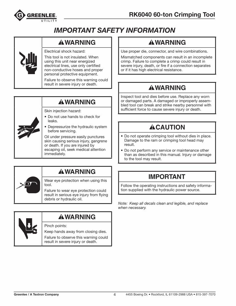
IMPORTANT SAFETY INFORMATION
Electrical shock hazard:
This tool is not insulated. When using this unit near energized electrical lines, use only certified non- conductive hoses and proper personal protective equipment.
Failure to observe this warning could result in severe injury or death.
Skin injection hazard:
Do not use hands to check for • leaks.
Depressurize the hydraulic system • before servicing.
Oil under pressure easily punctures skin causing serious injury, gangrene or death. If you are injured by escaping oil, seek medical attention immediately.
Wear eye protection when using this tool.
Failure to wear eye protection could result in serious eye injury from flying debris or hydraulic oil.
Pinch points:
Keep hands away from closing dies.
Failure to observe this warning could result in severe injury or death.
Use proper die, connector, and wire combinations.
Mismatched components can result in an incomplete crimp. Failure to complete a crimp could result in severe injury, death, or fire if a connection separates or if it has high electrical resistance.
Inspect tool and dies before use. Replace any worn or damaged parts. A damaged or improperly assem-bled tool can break and strike nearby personnel with sufficient force to cause severe injury or death.
Do not operate crimping tool without dies in place. • Damage to the ram or crimping tool head may result.
Do not perform any service or maintenance other • than as described in this manual. Injury or damage to the tool may result.
Follow the operating instructions and safety informa-tion supplied with the hydraulic power source.
Note: Keep all decals clean and legible, and replace when necessary.

RK6040 60-ton Crimping Tool
Greenlee / A Textron Company 4455 Boeing Dr. • Rockford, IL 61109-2988 USA • 815-397-70705
2
6
7
5
1
4
3
Specifications
Weight ......................................................................................................20.2 kg (45 lb)
Width ......................................................................................................152.5 mm (6")
Height ...................................................................................................431.8 mm (17")
Stroke (with dies) ....................................................................................37.8 mm (1.5")
Die Type ........................................................... Burndy “L” type and Alcoa 6000 series
Crimp Force ......................................................................................... 530 kN (60 tons)
Power Source Required .................................................................700 bar (10,000 psi)
Oil Capacity Required.........................................................................312 cc (0.75 pint)
RK6040
1. Die Release Buttons
2. Head Die Retaining Pin
3. Ram Die Retaining Pin
4. Stand
5. Cap Release Lever
6. Lifting Eye
7. Hydraulic Coupling (3/8 threaded, female)
Identification
RK6040 60-ton Crimping Tool
Greenlee / A Textron Company 4455 Boeing Dr. • Rockford, IL 61109-2988 USA • 815-397-70706
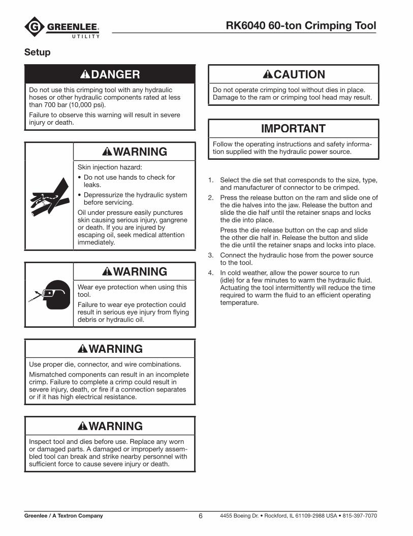
Setup
Do not use this crimping tool with any hydraulic hoses or other hydraulic components rated at less than 700 bar (10,000 psi).
Failure to observe this warning will result in severe injury or death.
Skin injection hazard:
Do not use hands to check for • leaks.
Depressurize the hydraulic system • before servicing.
Oil under pressure easily punctures skin causing serious injury, gangrene or death. If you are injured by escaping oil, seek medical attention immediately.
Wear eye protection when using this tool.
Failure to wear eye protection could result in serious eye injury from flying debris or hydraulic oil.
Use proper die, connector, and wire combinations.
Mismatched components can result in an incomplete crimp. Failure to complete a crimp could result in severe injury, death, or fire if a connection separates or if it has high electrical resistance.
Inspect tool and dies before use. Replace any worn or damaged parts. A damaged or improperly assem-bled tool can break and strike nearby personnel with sufficient force to cause severe injury or death.
Do not operate crimping tool without dies in place. Damage to the ram or crimping tool head may result.
Follow the operating instructions and safety informa-tion supplied with the hydraulic power source.
1. Select the die set that corresponds to the size, type, and manufacturer of connector to be crimped.
2. Press the release button on the ram and slide one of the die halves into the jaw. Release the button and slide the die half until the retainer snaps and locks the die into place.
Press the die release button on the cap and slide the other die half in. Release the button and slide the die until the retainer snaps and locks into place.
3. Connect the hydraulic hose from the power source to the tool.
4. In cold weather, allow the power source to run (idle) for a few minutes to warm the hydraulic fluid. Actuating the tool intermittently will reduce the time required to warm the fluid to an efficient operating temperature.

RK6040 60-ton Crimping Tool
Greenlee / A Textron Company 4455 Boeing Dr. • Rockford, IL 61109-2988 USA • 815-397-70707
Operation
Electrical shock hazard:
This tool is not insulated. When using this unit near energized electrical lines, use only certified non- conductive hoses and proper personal protective equipment.
Failure to observe this warning could result in severe injury or death.
Pinch points:
Keep hands away from closing dies.
Failure to observe this warning could result in severe injury or death.
Note: Consult the connector manufacturer’s instructions for the proper crimping procedure and proper die(s), etc.
1. Prepare the cable by stripping off the appropriate amount of insulation.
2. Select a connector that corresponds to the conduc-tor and the application.
3. Insert the conductor into the connector. Position the connector between the crimping dies.
4. Activate the hydraulic power source until the ram has advanced and the crimp is completed.
Note: To assure a complete crimp, verify that the power source has reached 700 bar (10,000 psi). Refer to “Periodic Relief Valve Check” in this manual.
5. Stop the power source and allow the ram to retract.
Maintenance
Keep the tool clean. Use the tool with care to keep dirt • and grit out of the hydraulic system. Contamination is the most common cause of failure for hydraulic tools.
Store the tool in its original case with the ram fully • retracted.
Occasionally lubricate the die release button • assemblies. A molybdenum disulfide grease is recommended.
Inspect the hydraulic hoses periodically.•
Periodically verify that the power source reaches • 700 bar (10,000 psi). Refer to “Periodic Relief Valve Check” in this manual.
Periodic Relief Valve Check
Periodically verify that your hydraulic power source is supplying between 9600 psi and 10,400 psi (662 bar and 717 bar).
Use a test-quality pressure gauge on the supply line from the hydraulic power source.
1. Refer to the instructions supplied with the pressure gauge.
2. Stop the flow of hydraulic oil from the power source.
3. Connect the pressure gauge to the supply line of the power source.
4. Install the set of test dies into the crimping tool.
5. Activate the power source until the ram has advanced and the power source reaches relief pressure. The pressure gauge should read between 9600 psi and 10,400 psi (662 bar and 717 bar) .
6. Release the pressure by stopping flow from your power source. The ram will retract.
If crimp pressures are low, the hydraulic power source relief valve may need adjustment.
Relief valve adjustments must be performed accord-ing to the instructions provided with the hydraulic power source.
RK6040 60-ton Crimping Tool
Greenlee / A Textron Company 4455 Boeing Dr. • Rockford, IL 61109-2988 USA • 815-397-70708
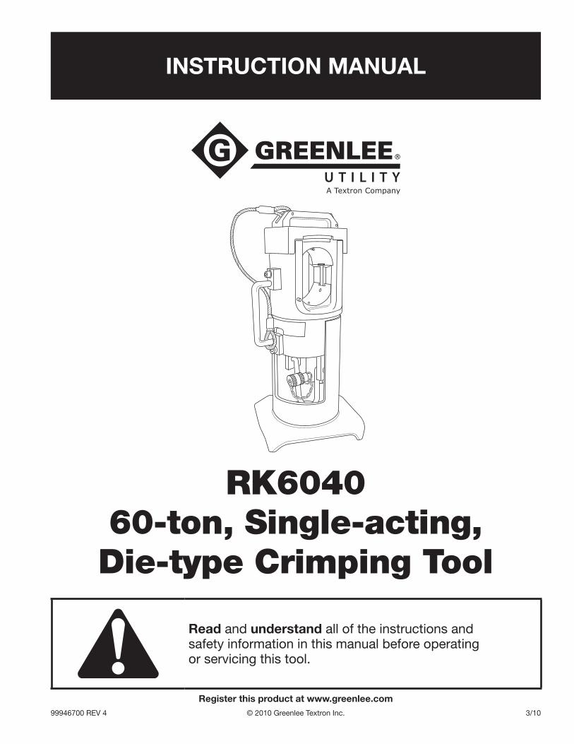
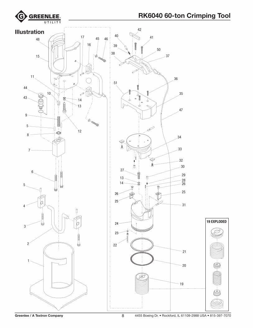
Illustration
19 EXPLODED
1
2
3
4
5
6
7
8
5
9
10
44
43
12
14
13
11
16
45 46
47
34
33
32
2730
2928
21
20
19
22
31
1314
42
50
3738
36
35
4140
39
51
17
15
48
26
2526
25
24
23
RK6040 60-ton Crimping Tool
Greenlee / A Textron Company 4455 Boeing Dr. • Rockford, IL 61109-2988 USA • 815-397-70709
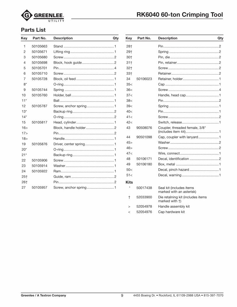
Parts List
1 50105663 Stand ....................................................1
2 50105671 Lifting ring .............................................1
3 50105680 Screw ....................................................2
4 50105698 Block, hook guide .................................2
5 50105701 Pin .........................................................4
6 50105710 Screw ....................................................2
7 50105728 Block, oil feed .......................................1
8* O-ring ....................................................1
9 50105744 Spring ...................................................1
10 50105760 Holder, ball ............................................1
11* Ball ........................................................1
12 50105787 Screw, anchor spring ............................1
13* Backup ring ...........................................2
14* O-ring ....................................................2
15 50105817 Head, cylinder .......................................1
16> Block, handle holder .............................2
17> Pin .........................................................2
18> Handle ...................................................1
19 50105876 Driver, center spring ..............................1
20* O-ring ....................................................1
21* Backup ring ...........................................1
22 50105906 Screw ....................................................1
23 50105914 Washer ..................................................1
24 50105922 Ram.......................................................1
25† Guide, ram ............................................2
26† Pin .........................................................2
27 50105957 Screw, anchor spring ............................1
Key Part No. Description Qty Key Part No. Description Qty
28† Pin .........................................................2
29† Spring ...................................................2
30† Pin, die ..................................................2
31† Pin, retainer ...........................................2
32† Screw ....................................................2
33† Retainer .................................................2
34 50106023 Retainer, holder .....................................1
35< Cap .......................................................1
36< Screw ....................................................4
37< Handle, head cap ..................................1
38< Pin .........................................................2
39< Spring ...................................................1
40< Pin .........................................................1
41< Screw ....................................................2
42< Switch, release ......................................1
43 90508076 Coupler, threaded female, 3/8" (includes item 44) ..................................1
44 90501098 Cap, coupler with lanyard .....................1
45> Washer ..................................................2
46> Screw ....................................................2
47< Wire, connect ........................................1
48 50106171 Decal, identification ..............................2
49 50106180 Box, metal ............................................1
50< Decal, pinch hazard ..............................1
51< Decal, warning ......................................1
Kits * 50017438 Seal kit (includes items marked with an asterisk)
† 52033900 Die retaIning kit (includes items marked with †)
> 52054978 Handle assembly kit
< 52054976 Cap hardware kit

USA 800-435-0786 Fax: 800-451-2632 815-397-7070 Fax: 815-397-1865Canada 800-435-0786 Fax: 800-524-2853International +1-815-397-7070 Fax: +1-815-397-9247
4455 Boeing Drive • Rockford, IL 61109-2988 • USA • 815-397-7070An ISO 9001 Company • Greenlee Textron Inc. is a subsidiary of Textron Inc.
www.greenlee.com