Embed Size (px)
Citation preview
APPLICATION NOTE
R01AN1296EJ0120 Rev. 1.20 Page 1 of 22
May 16, 2014
RL78 Family IEC60730/60335 oriented Self Test additional Library
Introduction
Today, as automatic electronic controls systems continue to expand into many diverse applications, the requirement of reliability and safety are becoming an ever increasing factor in system design.
For example, the introduction of the IEC60730 safety standard for household appliances requires manufactures to design automatic electronic controls that ensure safe and reliable operation of their products.
The IEC60730 standard covers all aspects of product design but Annex H is of key importance for design of Microcontroller based control systems. This provides three software classifications for automatic electronic controls:
1. Class A: Control functions, which are not intended to be relied upon for the safety of the equipment.
Examples: Room thermostats, humidity controls, lighting controls, timers, and switches.
2. Class B: Control functions, which are intended to prevent unsafe operation of the controlled equipment.
Examples: Thermal cut-offs and door locks for laundry equipment.
3. Class C: Control functions, which are intended to prevent special hazards
Examples: Automatic burner controls and thermal cut-outs for closed.
Appliances such as washing machines, dishwashers, dryers, refrigerators, freezers, and Cookers / Stoves will tend to fall under the classification of Class B.
This Application Note provides guidelines of how to use flexible sample software routines to assist with compliance with IEC60730/60335 class B safety standards.
Although these routines were developed on the assumption of trying IEC60730/60335 compliance test as a basis, they can be implemented in any system for self testing of Renesas Microcontroller families.
These software routines provided are designed to be used after the system power on, or reset condition and also during the application program execution. The end user has the flexibility of what routines are included and how to integrate these routines into their overall application system design. This document and the accompanying test harness code provide examples of how to do this.
Note. This document is made imagining the European Norm EN60335-1:2002/A1:2004 Annex R, in which the Norm IEC 60730-1 (EN60730-1:2000) is used in some points. The Annex R of the mentioned Norm contains just a single sheet that jumps to the IEC 60730-1 for definitions, information and applicable paragraphs.
R01AN1296EJ0120Rev. 1.20
May 16, 2014
RL78 Family IEC60730/60335 oriented Self Test additional Library
R01AN1296EJ0120 Rev. 1.20 Page 2 of 22
May 16, 2014
Target Devices
RL78 Family Microcontrollers (except RL78/G10 Group)
RL78 Family IEC60730/60335 oriented Self Test additional Library
R01AN1296EJ0120 Rev. 1.20 Page 3 of 22
May 16, 2014
Contents
1. Self Test Libraries Introduction ......................................................................................................... 4 Interrupt ............................................................................................................................................. 4 ADC ................................................................................................................................................... 4 PORT ................................................................................................................................................ 4 SERIAL COMMUNICATION ............................................................................................................. 4
2. Self Test Library Functions ............................................................................................................... 5 2.4 Interrupt Tests ................................................................................................................................... 5 2.5 ADC Tests ......................................................................................................................................... 6 2.6 PORT Tests ....................................................................................................................................... 7 2.7 SERIAL Tests .................................................................................................................................... 8
3 Benchmarking ................................................................................................................................. 10
3.1 Development Environment .............................................................................................................. 10 3.2 Cubesuite+ Settings ........................................................................................................................ 10 4 Additional Hardware Resources ...................................................................................................... 13
Revision Record ...................................................................................................................................... 20
General Precautions in the Handling of MPU/MCU Products ................................................................. 21
RL78 Family IEC60730/60335 oriented Self Test additional Library
R01AN1296EJ0120 Rev. 1.20 Page 4 of 22
May 16, 2014
1. Self Test Libraries Introduction
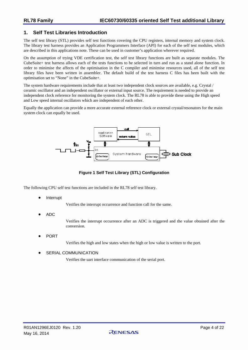
The self test library (STL) provides self test functions covering the CPU registers, internal memory and system clock. The library test harness provides an Application Programmers Interface (API) for each of the self test modules, which are described in this applications note. These can be used in customer’s application wherever required.
On the assumption of trying VDE certification test, the self test library functions are built as separate modules. The CubeSuite+ test harness allows each of the tests functions to be selected in turn and run as a stand alone function. In order to minimise the affects of the optimisation in the C compiler and minimise resources used, all of the self test library files have been written in assembler. The default build of the test harness C files has been built with the optimisation set to “None” in the CubeSuite+.
The system hardware requirements include that at least two independent clock sources are available, e.g. Crystal / ceramic oscillator and an independent oscillator or external input source. The requirement is needed to provide an independent clock reference for monitoring the system clock. The RL78 is able to provide these using the High speed and Low speed internal oscillators which are independent of each other.
Equally the application can provide a more accurate external reference clock or external crystal/resonators for the main system clock can equally be used.
Figure 1 Self Test Library (STL) Configuration
The following CPU self test functions are included in the RL78 self test library.
Interrupt
Verifies the interrupt occurrence and function call for the same.
ADC
Verifies the interrupt occurrence after an ADC is triggered and the value obtained after the conversion.
PORT
Verifies the high and low states when the high or low value is written to the port.
SERIAL COMMUNICATION
Verifies the uart interface communication of the serial port.
RL78 Family IEC60730/60335 oriented Self Test additional Library
R01AN1296EJ0120 Rev. 1.20 Page 5 of 22
May 16, 2014
2. Self Test Library Functions
2.1 Interrupt Tests
This section describes Interrupt tests routines. The test harness control file ‘main.c’ provides examples of the API for each of the Interrupt tests using “C” language.
These modules test Interrupt operation.
The following Interrupts are tested:
o INTP0
RL78 Family IEC60730/60335 oriented Self Test additional Library
R01AN1296EJ0120 Rev. 1.20 Page 6 of 22
May 16, 2014
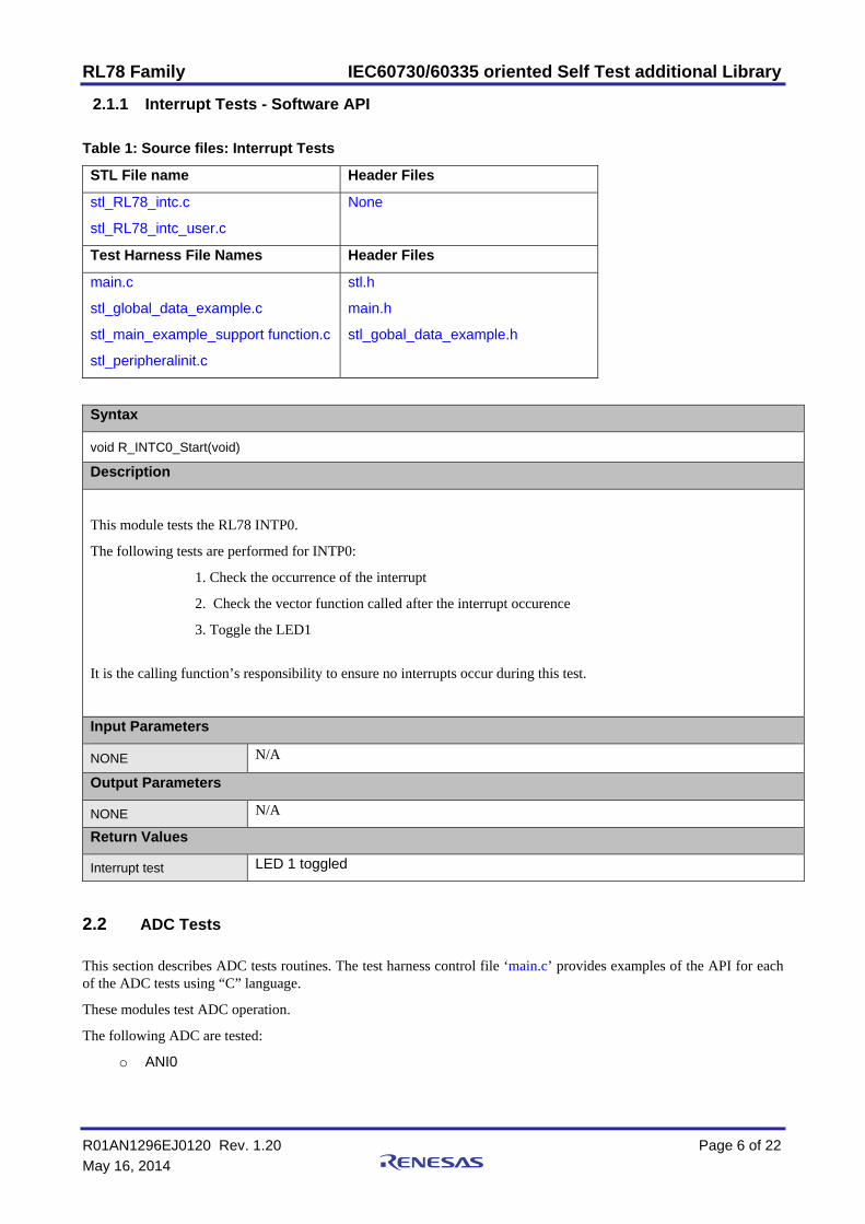
2.1.1 Interrupt Tests - Software API
Table 1: Source files: Interrupt Tests
STL File name Header Files
stl_RL78_intc.c
stl_RL78_intc_user.c
None
Test Harness File Names Header Files
main.c
stl_global_data_example.c
stl_main_example_support function.c
stl_peripheralinit.c
stl.h
main.h
stl_gobal_data_example.h
Syntax
void R_INTC0_Start(void)
Description
This module tests the RL78 INTP0.
The following tests are performed for INTP0:
1. Check the occurrence of the interrupt
2. Check the vector function called after the interrupt occurence
3. Toggle the LED1
It is the calling function’s responsibility to ensure no interrupts occur during this test.
Input Parameters
NONE N/A
Output Parameters
NONE N/A
Return Values
Interrupt test LED 1 toggled
2.2 ADC Tests
This section describes ADC tests routines. The test harness control file ‘main.c’ provides examples of the API for each of the ADC tests using “C” language.
These modules test ADC operation.
The following ADC are tested:
o ANI0
RL78 Family IEC60730/60335 oriented Self Test additional Library
R01AN1296EJ0120 Rev. 1.20 Page 7 of 22
May 16, 2014
2.2.1 ADC Tests - Software API
Table 2: Source files: Interrupt Tests
STL File name Header Files
stl_RL78_adc.c
stl_RL78_adc_user.c
None
Test Harness File Names Header Files
Main.c
stl_global_data_example.c
stl_main_example_support function.c
stl_peripheralinit.c
stl.h
main.h
stl_gobal_data_example.h
Syntax
void R_ADC_Start(void)
Description
This module tests the RL78 ANI0.
The following tests are performed for ANI0:
1. Check the occurrence of the interrupt for ANI0
2. Check the vector function called after the interrupt occurence
3. Check the value got after adc conversion.
It is the calling function’s responsibility to ensure no interrupts occur during this test.
Input Parameters
NONE N/A
Output Parameters
NONE N/A
Return Values
ADC test ADC value read
2.3 PORT Tests
This section describes port tests routines. The test harness control file ‘main.c’ provides examples of the API for each of the port tests using “C” language.
These modules test port operation.
The following port are tested:
o PORT 6
RL78 Family IEC60730/60335 oriented Self Test additional Library
R01AN1296EJ0120 Rev. 1.20 Page 8 of 22
May 16, 2014
2.3.1 PORT Tests - Software API
Table 3: Source files: Interrupt Tests
STL File name Header Files
stl_RL78_port.c
None
Test Harness File Names Header Files
main.c
stl_global_data_example.c
stl_main_example_support function.c
stl_peripheralinit.c
stl.h
main.h
stl_gobal_data_example.h
Syntax
None
Description
This module tests the RL78 PORT 6.
The following tests are performed for PORT 6:
1. Check the output state of PORT 6
2. Check the output of the port 6
3. Check the output high or low state.
It is the calling function’s responsibility to ensure no interrupts occur during this test.
Input Parameters
NONE N/A
Output Parameters
NONE N/A
Return Values
PORT test LED 1 toggles according to output state
2.4 SERIAL Tests
This section describes serial tests routines. The test harness control file ‘main.c’ provides examples of the API for each of the serial tests using “C” language.
These modules test serial operation.
The following serial port are tested:
o UART0
RL78 Family IEC60730/60335 oriented Self Test additional Library
R01AN1296EJ0120 Rev. 1.20 Page 9 of 22
May 16, 2014
2.4.1 Serial Tests - Software API
Table 4: Source files: Serial Tests
STL File name Header Files
stl_RL78_serial.c
stl_RL78_serial_user.c
None
Test Harness File Names Header Files
main.c
stl_global_data_example.c
stl_main_example_support function.c
stl_peripheralinit.c
stl.h
main.h
stl_gobal_data_example.h
Syntax
void UART_test(void)
Description
This module tests the RL78 UART0.
The following tests are performed for UART):
1. Check the output value written to the transmit pin
2. Check the loop back and the value received on the receive pin
3. Check the interrupt occurrence of the receive pin.
It is the calling function’s responsibility to ensure no interrupts occur during this test.
Input Parameters
NONE N/A
Output Parameters
NONE N/A
Return Values
UART test Value read on the receive pin
RL78 Family IEC60730/60335 oriented Self Test additional Library
R01AN1296EJ0120 Rev. 1.20 Page 10 of 22
May 16, 2014
3 Benchmarking
1.1 Development Environment
IECUBE - QB-RL78G14-ZZZ-EE Full RL78/G14 In circuit Emulator
QB-R5F104LE-TB RL78/G14 Target Board 64pin LQFP (10 x 10mm)
Tool chain: Cubesuite+ Version 1.00.01
MCU: R5F104LE
Internal Clock: 32 MHz High Speed Oscillator System Clock = 32 MHz
External Sub Clock: 32 KHz
1.2 Cubesuite+ Settings
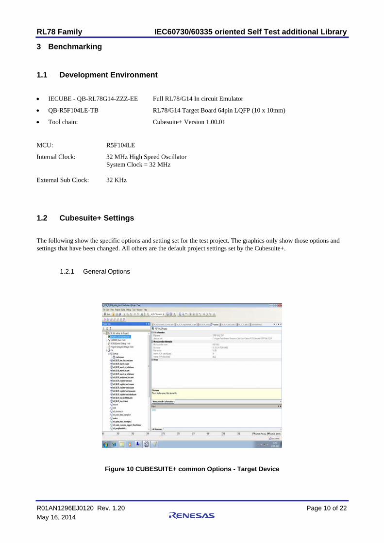
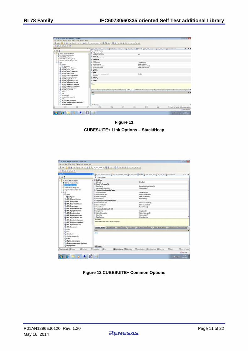
The following show the specific options and setting set for the test project. The graphics only show those options and settings that have been changed. All others are the default project settings set by the Cubesuite+.
1.2.1 General Options
Figure 10 CUBESUITE+ common Options - Target Device
RL78 Family IEC60730/60335 oriented Self Test additional Library
R01AN1296EJ0120 Rev. 1.20 Page 11 of 22
May 16, 2014
Figure 11
CUBESUITE+ Link Options – Stack/Heap
Figure 12 CUBESUITE+ Common Options
RL78 Family IEC60730/60335 oriented Self Test additional Library
R01AN1296EJ0120 Rev. 1.20 Page 12 of 22
May 16, 2014
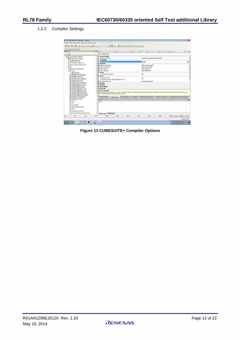
1.2.2 Complier Settings
Figure 13 CUBESUITE+ Compiler Options
RL78 Family IEC60730/60335 oriented Self Test additional Library
R01AN1296EJ0120 Rev. 1.20 Page 13 of 22
May 16, 2014
4 Additional Hardware Resources The following additional safety and self test features have been included in the RL78 family to provide support for the user. While these additional functions have not been certified by VDE, they provide a valuable extra resource to the user and are included here for reference.
4.1 Additional Safety Functions The following additional safety functions have been included in the RL78 family MCU devices. As for further and more detailed information, please refer to the User’s Manual (: Hardware) of each product group.
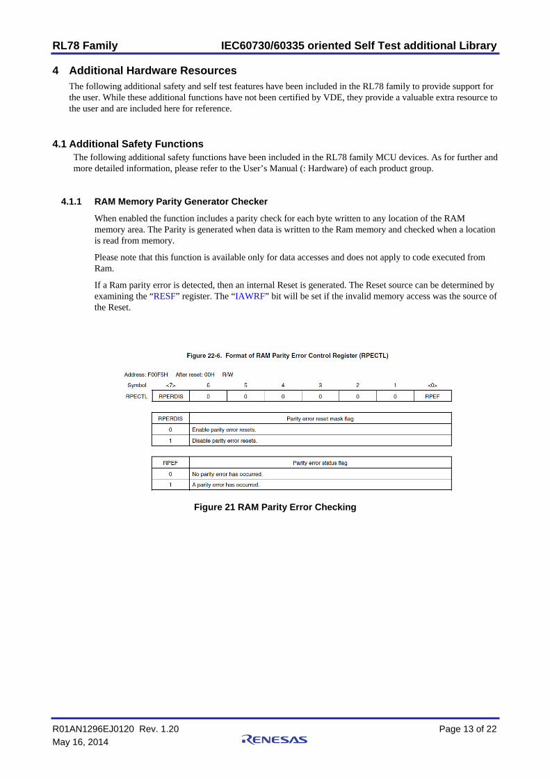
4.1.1 RAM Memory Parity Generator Checker
When enabled the function includes a parity check for each byte written to any location of the RAM memory area. The Parity is generated when data is written to the Ram memory and checked when a location is read from memory.
Please note that this function is available only for data accesses and does not apply to code executed from Ram.
If a Ram parity error is detected, then an internal Reset is generated. The Reset source can be determined by examining the “RESF” register. The “IAWRF” bit will be set if the invalid memory access was the source of the Reset.
Figure 21 RAM Parity Error Checking
RL78 Family IEC60730/60335 oriented Self Test additional Library
R01AN1296EJ0120 Rev. 1.20 Page 14 of 22
May 16, 2014
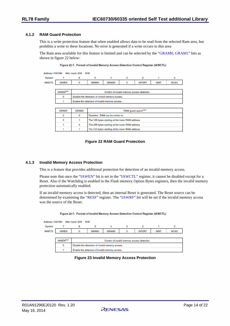
4.1.2 RAM Guard Protection
This is a write protection feature that when enabled allows data to be read from the selected Ram area, but prohibits a write to these locations. No error is generated if a write occurs to this area
The Ram area available for this feature is limited and can be selected by the “GRAM0, GRAM1” bits as shown in figure 22 below:
Figure 22 RAM Guard Protection
4.1.3 Invalid Memory Access Protection
This is a feature that provides additional protection for detection of an invalid memory access.
Please note that once the “IAWEN” bit is set in the “IAWCTL” register, it cannot be disabled except for a Reset. Also if the Watchdog is enabled in the Flash memory Option Bytes registers, then the invalid memory protection automatically enabled.
If an invalid memory access is detected, then an internal Reset is generated. The Reset source can be determined by examining the “RESF” register. The “IAWRF” bit will be set if the invalid memory access was the source of the Reset.
Figure 23 Invalid Memory Access Protection
RL78 Family IEC60730/60335 oriented Self Test additional Library
R01AN1296EJ0120 Rev. 1.20 Page 15 of 22
May 16, 2014
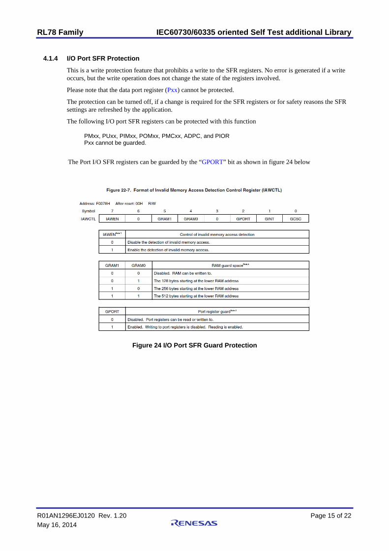
4.1.4 I/O Port SFR Protection
This is a write protection feature that prohibits a write to the SFR registers. No error is generated if a write occurs, but the write operation does not change the state of the registers involved.
Please note that the data port register (Pxx) cannot be protected.
The protection can be turned off, if a change is required for the SFR registers or for safety reasons the SFR settings are refreshed by the application.
The following I/O port SFR registers can be protected with this function PMxx, PUxx, PIMxx, POMxx, PMCxx, ADPC, and PIOR Pxx cannot be guarded.
The Port I/O SFR registers can be guarded by the “GPORT” bit as shown in figure 24 below
Figure 24 I/O Port SFR Guard Protection
RL78 Family IEC60730/60335 oriented Self Test additional Library
R01AN1296EJ0120 Rev. 1.20 Page 16 of 22
May 16, 2014
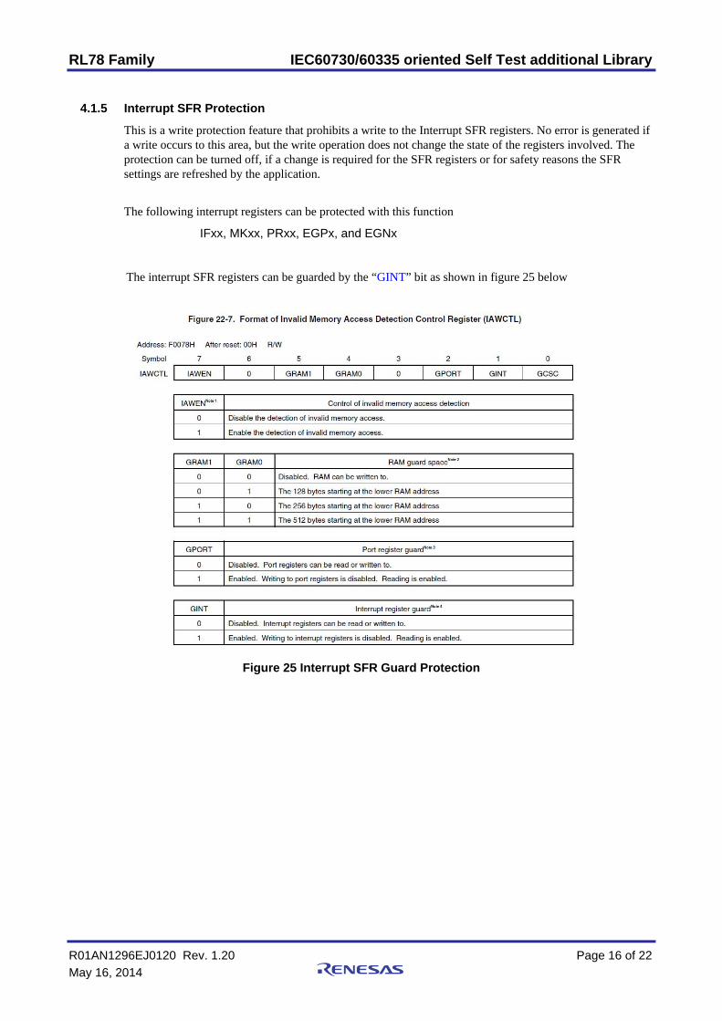
4.1.5 Interrupt SFR Protection
This is a write protection feature that prohibits a write to the Interrupt SFR registers. No error is generated if a write occurs to this area, but the write operation does not change the state of the registers involved. The protection can be turned off, if a change is required for the SFR registers or for safety reasons the SFR settings are refreshed by the application.
The following interrupt registers can be protected with this function
IFxx, MKxx, PRxx, EGPx, and EGNx
The interrupt SFR registers can be guarded by the “GINT” bit as shown in figure 25 below
Figure 25 Interrupt SFR Guard Protection
RL78 Family IEC60730/60335 oriented Self Test additional Library
R01AN1296EJ0120 Rev. 1.20 Page 17 of 22
May 16, 2014
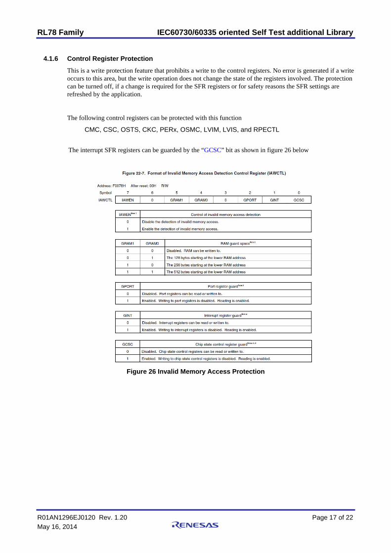
4.1.6 Control Register Protection
This is a write protection feature that prohibits a write to the control registers. No error is generated if a write occurs to this area, but the write operation does not change the state of the registers involved. The protection can be turned off, if a change is required for the SFR registers or for safety reasons the SFR settings are refreshed by the application.
The following control registers can be protected with this function
CMC, CSC, OSTS, CKC, PERx, OSMC, LVIM, LVIS, and RPECTL
The interrupt SFR registers can be guarded by the “GCSC” bit as shown in figure 26 below
Figure 26 Invalid Memory Access Protection
RL78 Family IEC60730/60335 oriented Self Test additional Library
R01AN1296EJ0120 Rev. 1.20 Page 18 of 22
May 16, 2014
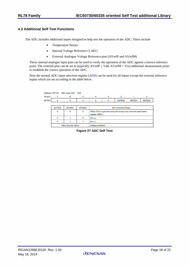
4.2 Additional Self Test Functions
The ADC includes additional inputs designed to help test the operation of the ADC. These include
Temperature Sensor
Internal Voltage Reference (1.44V)
External Analogue Voltage Reference pins (AVrefP and AVrefM)
These internal analogue input pins can be used to verify the operation of the ADC against a known reference point. The external pins can be set to (typically AVrefP < Vdd, AVrefM = Vss) additional measurement point to establish the correct operation of the ADC.
Note the normal ADC input selection register (ADS) can be used for all inputs except the external reference inputs which are set according to the table below.
Figure 27 ADC Self Test
RL78 Family IEC60730/60335 oriented Self Test additional Library
R01AN1296EJ0120 Rev. 1.20 Page 19 of 22
May 16, 2014
Website and Support
Renesas Electronics Website http://www.renesas.com/
Inquiries
http://www.renesas.com/inquiry
All trademarks and registered trademarks are the property of their respective owners.
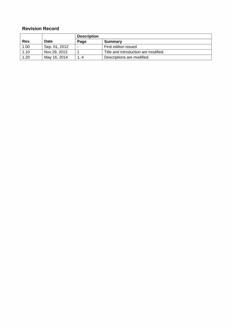
Revision Record
Rev.
Date
Description Page Summary
1.00 Sep. 01, 2012 - First edition issued 1.10 Nov.29, 2013 1 Title and Introduction are modified. 1.20 May 16, 2014 1, 4 Descriptions are modified.
General Precautions in the Handling of MPU/MCU Products
The following usage notes are applicable to all MPU/MCU products from Renesas. For detailed usage notes on the products covered by this manual, refer to the relevant sections of the manual. If the descriptions under General Precautions in the Handling of MPU/MCU Products and in the body of the manual differ from each other, the description in the body of the manual takes precedence.
1. Handling of Unused Pins Handle unused pins in accord with the directions given under Handling of Unused Pins in the manual. The input pins of CMOS products are generally in the high-impedance state. In operation with an unused pin
in the open-circuit state, extra electromagnetic noise is induced in the vicinity of LSI, associated shoot-through current flows internally, and malfunctions occur due to the false recognition of the pin state as an input signal become possible. Unused pins should be handled as described under Handling of Unused Pins in the manual.
2. Processing at Power-on The state of the product is undefined at the moment when power is supplied. The states of internal circuits in the LSI are indeterminate and the states of register settings and pins are
undefined at the moment when power is supplied. In a finished product where the reset signal is applied to the external reset pin, the states of pins are not guaranteed from the moment when power is supplied until the reset process is completed. In a similar way, the states of pins in a product that is reset by an on-chip power-on reset function are not guaranteed from the moment when power is supplied until the power reaches the level at which resetting has been specified.
3. Prohibition of Access to Reserved Addresses Access to reserved addresses is prohibited. The reserved addresses are provided for the possible future expansion of functions. Do not access these
addresses; the correct operation of LSI is not guaranteed if they are accessed. 4. Clock Signals
After applying a reset, only release the reset line after the operating clock signal has become stable. When switching the clock signal during program execution, wait until the target clock signal has stabilized. When the clock signal is generated with an external resonator (or from an external oscillator) during a reset,
ensure that the reset line is only released after full stabilization of the clock signal. Moreover, when switching to a clock signal produced with an external resonator (or by an external oscillator) while program execution is in progress, wait until the target clock signal is stable.
5. Differences between Products Before changing from one product to another, i.e. to one with a different type number, confirm that the change will not lead to problems. The characteristics of MPU/MCU in the same group but having different type numbers may differ because of
the differences in internal memory capacity and layout pattern. When changing to products of different type numbers, implement a system-evaluation test for each of the products.
Notice1. Descriptions of circuits, software and other related information in this document are provided only to illustrate the operation of semiconductor products and application examples. You are fully responsible for
the incorporation of these circuits, software, and information in the design of your equipment. Renesas Electronics assumes no responsibility for any losses incurred by you or third parties arising from the
use of these circuits, software, or information.
2. Renesas Electronics has used reasonable care in preparing the information included in this document, but Renesas Electronics does not warrant that such information is error free. Renesas Electronics
assumes no liability whatsoever for any damages incurred by you resulting from errors in or omissions from the information included herein.
3. Renesas Electronics does not assume any liability for infringement of patents, copyrights, or other intellectual property rights of third parties by or arising from the use of Renesas Electronics products or
technical information described in this document. No license, express, implied or otherwise, is granted hereby under any patents, copyrights or other intellectual property rights of Renesas Electronics or
others.
4. You should not alter, modify, copy, or otherwise misappropriate any Renesas Electronics product, whether in whole or in part. Renesas Electronics assumes no responsibility for any losses incurred by you or
third parties arising from such alteration, modification, copy or otherwise misappropriation of Renesas Electronics product.
5. Renesas Electronics products are classified according to the following two quality grades: "Standard" and "High Quality". The recommended applications for each Renesas Electronics product depends on
the product's quality grade, as indicated below.
"Standard": Computers; office equipment; communications equipment; test and measurement equipment; audio and visual equipment; home electronic appliances; machine tools; personal electronic
equipment; and industrial robots etc.
"High Quality": Transportation equipment (automobiles, trains, ships, etc.); traffic control systems; anti-disaster systems; anti-crime systems; and safety equipment etc.
Renesas Electronics products are neither intended nor authorized for use in products or systems that may pose a direct threat to human life or bodily injury (artificial life support devices or systems, surgical
implantations etc.), or may cause serious property damages (nuclear reactor control systems, military equipment etc.). You must check the quality grade of each Renesas Electronics product before using it
in a particular application. You may not use any Renesas Electronics product for any application for which it is not intended. Renesas Electronics shall not be in any way liable for any damages or losses
incurred by you or third parties arising from the use of any Renesas Electronics product for which the product is not intended by Renesas Electronics.
6. You should use the Renesas Electronics products described in this document within the range specified by Renesas Electronics, especially with respect to the maximum rating, operating supply voltage
range, movement power voltage range, heat radiation characteristics, installation and other product characteristics. Renesas Electronics shall have no liability for malfunctions or damages arising out of the
use of Renesas Electronics products beyond such specified ranges.
7. Although Renesas Electronics endeavors to improve the quality and reliability of its products, semiconductor products have specific characteristics such as the occurrence of failure at a certain rate and
malfunctions under certain use conditions. Further, Renesas Electronics products are not subject to radiation resistance design. Please be sure to implement safety measures to guard them against the
possibility of physical injury, and injury or damage caused by fire in the event of the failure of a Renesas Electronics product, such as safety design for hardware and software including but not limited to
redundancy, fire control and malfunction prevention, appropriate treatment for aging degradation or any other appropriate measures. Because the evaluation of microcomputer software alone is very difficult,
please evaluate the safety of the final products or systems manufactured by you.
8. Please contact a Renesas Electronics sales office for details as to environmental matters such as the environmental compatibility of each Renesas Electronics product. Please use Renesas Electronics
products in compliance with all applicable laws and regulations that regulate the inclusion or use of controlled substances, including without limitation, the EU RoHS Directive. Renesas Electronics assumes
no liability for damages or losses occurring as a result of your noncompliance with applicable laws and regulations.
9. Renesas Electronics products and technology may not be used for or incorporated into any products or systems whose manufacture, use, or sale is prohibited under any applicable domestic or foreign laws or
regulations. You should not use Renesas Electronics products or technology described in this document for any purpose relating to military applications or use by the military, including but not limited to the
development of weapons of mass destruction. When exporting the Renesas Electronics products or technology described in this document, you should comply with the applicable export control laws and
regulations and follow the procedures required by such laws and regulations.
10. It is the responsibility of the buyer or distributor of Renesas Electronics products, who distributes, disposes of, or otherwise places the product with a third party, to notify such third party in advance of the
contents and conditions set forth in this document, Renesas Electronics assumes no responsibility for any losses incurred by you or third parties as a result of unauthorized use of Renesas Electronics
products.
11. This document may not be reproduced or duplicated in any form, in whole or in part, without prior written consent of Renesas Electronics.
12. Please contact a Renesas Electronics sales office if you have any questions regarding the information contained in this document or Renesas Electronics products, or if you have any other inquiries.
(Note 1) "Renesas Electronics" as used in this document means Renesas Electronics Corporation and also includes its majority-owned subsidiaries.
(Note 2) "Renesas Electronics product(s)" means any product developed or manufactured by or for Renesas Electronics.
http://www.renesas.comRefer to "http://www.renesas.com/" for the latest and detailed information.
Renesas Electronics America Inc.2880 Scott Boulevard Santa Clara, CA 95050-2554, U.S.A.Tel: +1-408-588-6000, Fax: +1-408-588-6130Renesas Electronics Canada Limited1101 Nicholson Road, Newmarket, Ontario L3Y 9C3, CanadaTel: +1-905-898-5441, Fax: +1-905-898-3220Renesas Electronics Europe LimitedDukes Meadow, Millboard Road, Bourne End, Buckinghamshire, SL8 5FH, U.KTel: +44-1628-651-700, Fax: +44-1628-651-804Renesas Electronics Europe GmbHArcadiastrasse 10, 40472 Düsseldorf, GermanyTel: +49-211-65030, Fax: +49-211-6503-1327Renesas Electronics (China) Co., Ltd.7th Floor, Quantum Plaza, No.27 ZhiChunLu Haidian District, Beijing 100083, P.R.ChinaTel: +86-10-8235-1155, Fax: +86-10-8235-7679Renesas Electronics (Shanghai) Co., Ltd.Unit 301, Tower A, Central Towers, 555 LanGao Rd., Putuo District, Shanghai, ChinaTel: +86-21-2226-0888, Fax: +86-21-2226-0999Renesas Electronics Hong Kong LimitedUnit 1601-1613, 16/F., Tower 2, Grand Century Place, 193 Prince Edward Road West, Mongkok, Kowloon, Hong KongTel: +852-2886-9318, Fax: +852 2886-9022/9044Renesas Electronics Taiwan Co., Ltd.13F, No. 363, Fu Shing North Road, Taipei, TaiwanTel: +886-2-8175-9600, Fax: +886 2-8175-9670Renesas Electronics Singapore Pte. Ltd.80 Bendemeer Road, Unit #06-02 Hyflux Innovation Centre Singapore 339949Tel: +65-6213-0200, Fax: +65-6213-0300Renesas Electronics Malaysia Sdn.Bhd.Unit 906, Block B, Menara Amcorp, Amcorp Trade Centre, No. 18, Jln Persiaran Barat, 46050 Petaling Jaya, Selangor Darul Ehsan, MalaysiaTel: +60-3-7955-9390, Fax: +60-3-7955-9510Renesas Electronics Korea Co., Ltd.12F., 234 Teheran-ro, Gangnam-Gu, Seoul, 135-080, KoreaTel: +82-2-558-3737, Fax: +82-2-558-5141
SALES OFFICES
© 2014 Renesas Electronics Corporation. All rights reserved. Colophon 3.0