Embed Size (px)
DESCRIPTION
Help online RMXprt
Citation preview

Table of Contents
1. Getting Started with RMxprtCreating a Project and Inserting a New RMxprt Design . . 1-3Opening Existing RMxprt Projects and Saving as New . . 1-4
Opening RMxprt Projects . . . . . . . . . . . . . . . . . . . . . . . . . 1-4
Opening Recent RMxprt Projects . . . . . . . . . . . . . . . . . . . 1-4
Saving RMxprt Projects . . . . . . . . . . . . . . . . . . . . . . . . . . . 1-4
Saving a New RMxprt Project . . . . . . . . . . . . . . . . . . . . . . 1-4
Saving the Active RMxprt Project . . . . . . . . . . . . . . . . . . . 1-5
Saving a Copy of an RMxprt Project . . . . . . . . . . . . . . . . . 1-5
Saving RMxprt Project Data Automatically . . . . . . . . . . . . 1-5Recovering RMxprt Project Data in an Auto-Save File . . 1-6
RMxprt Files . . . . . . . . . . . . . . . . . . . . . . . . . . . . . . . . . . . . 1-7
Saving Project Notes in RMxprt . . . . . . . . . . . . . . . . . . . . 1-7
The RMxprt Desktop . . . . . . . . . . . . . . . . . . . . . . . . . . . . . 1-8RMxprt Title Bar . . . . . . . . . . . . . . . . . . . . . . . . . . . . . . . . . 1-9
Working with the RMxprt Menu Bar . . . . . . . . . . . . . . . . . 1-10
Working with the RMxprt Shortcut Menus . . . . . . . . . . . . . 1-11Shortcut Menu in the Toolbars Area . . . . . . . . . . . . . . . . 1-11
Shortcut Menus in the Project Manager Window . . . . . . 1-11
Working with the RMxprt Toolbars . . . . . . . . . . . . . . . . . . 1-12Undoing RMxprt Commands . . . . . . . . . . . . . . . . . . . . . . 1-12
Contents-1
Release 14.5 - © SAS IP, Inc. All rights reserved. - Contains proprietary and confidential information of ANSYS, Inc. and its subsidiaries and affiliates.

Maxwell Online Help
Redoing RMxprt Commands . . . . . . . . . . . . . . . . . . . . . . 1-12
Working with the RMxprt Status Bar . . . . . . . . . . . . . . . . . 1-13
Working with the RMxprt Machine Editor Windows . . . . . 1-13Setting the Window View . . . . . . . . . . . . . . . . . . . . . . . . . 1-14
Printing in RMxprt . . . . . . . . . . . . . . . . . . . . . . . . . . . . . . . 1-14
Working with the RMxprt Project Manager . . . . . . . . . . . . 1-15Working with the RMxprt Project Tree . . . . . . . . . . . . . . . 1-15
Viewing RMxprt Design Details . . . . . . . . . . . . . . . . . . . . 1-15
Working with the RMxprt Properties Window . . . . . . . . . . 1-16Showing and Hiding the RMxprt Properties Window . . . . 1-16
Working with the RMxprt Progress Window . . . . . . . . . . . 1-17
Working with the RMxprt Message Manager . . . . . . . . . . 1-17Clearing Messages for the RMxprt Project . . . . . . . . . . . 1-17
Clearing Messages for the RMxprt Model . . . . . . . . . . . . 1-17
Copying Messages in RMxprt . . . . . . . . . . . . . . . . . . . . . 1-17
Quick Start for RMxprt . . . . . . . . . . . . . . . . . . . . . . . . . . . . 1-19RMxprt Example Part 1: Create a New Project . . . . . . . . . 1-19
RMxprt Example Part 2: Select a Machine . . . . . . . . . . . . 1-19
RMxprt Example Part 3: Input Design Data . . . . . . . . . . . 1-20
RMxprt Example Part 4: Analyze the Design. . . . . . . . . . . 1-28
RMxprt Example Part 5: Create Reports and View Output 1-29
RMxprt Example Part 6: Output Design Data . . . . . . . . . . 1-34
2. Setting Up RMxprt ProjectsSetting Up A Machine Model . . . . . . . . . . . . . . . . . . . . . . . 2-2Changing the Machine Type . . . . . . . . . . . . . . . . . . . . . . . 2-3
SetMachineType . . . . . . . . . . . . . . . . . . . . . . . . . . . . . . . 2-3
Design Settings in RMxprt . . . . . . . . . . . . . . . . . . . . . . . . . 2-5Setting the Material Threshold in RMxprt . . . . . . . . . . . . . 2-5
RMxprt Export Options . . . . . . . . . . . . . . . . . . . . . . . . . . . 2-5
Setting User Defined Data File for a Design . . . . . . . . . . . 2-6
Validating RMxprt Projects . . . . . . . . . . . . . . . . . . . . . . . . 2-8Setting General Options in RMxprt . . . . . . . . . . . . . . . . . . 2-9
Contents-2
Release 14.5 - © SAS IP, Inc. All rights reserved. - Contains proprietary and confidential information of ANSYS, Inc. and its subsidiaries and affiliates.

Maxwell Online Help
Setting RMxprt Options . . . . . . . . . . . . . . . . . . . . . . . . . . . 2-10RMxprt Options: General Options Tab . . . . . . . . . . . . . . 2-10
RMxprt Options: Solver Tab . . . . . . . . . . . . . . . . . . . . . . . 2-11
Setting Machine Options . . . . . . . . . . . . . . . . . . . . . . . . . . 2-12Specifying the Material Threshold . . . . . . . . . . . . . . . . . . . 2-12
Setting Model Units . . . . . . . . . . . . . . . . . . . . . . . . . . . . . . 2-12
Specifying the Machine Option for Wire Setting . . . . . . . . 2-12
Editing Wire Data . . . . . . . . . . . . . . . . . . . . . . . . . . . . . . . . 2-13
Edit AC Windings . . . . . . . . . . . . . . . . . . . . . . . . . . . . . . . . 2-15Enable Winding Editor . . . . . . . . . . . . . . . . . . . . . . . . . . . . 2-15
Edit Winding Configuration . . . . . . . . . . . . . . . . . . . . . . . . 2-18
View Winding Connections . . . . . . . . . . . . . . . . . . . . . . . . 2-20
Working with the Slot Editor . . . . . . . . . . . . . . . . . . . . . . . . 2-21The Slot Editor Window . . . . . . . . . . . . . . . . . . . . . . . . . . . 2-23
Slot Editor Data Editing View . . . . . . . . . . . . . . . . . . . . . . 2-24
The New Slot Dialog Box . . . . . . . . . . . . . . . . . . . . . . . . . 2-27
Slot Editor Graphical View . . . . . . . . . . . . . . . . . . . . . . . . 2-28
Editing Slot Segments . . . . . . . . . . . . . . . . . . . . . . . . . . . . 2-28The Edit Slot Segment Dialog Box . . . . . . . . . . . . . . . . . . 2-30
Working with Variables in RMxprt . . . . . . . . . . . . . . . . . . . 2-35Adding a Project Variable in RMxprt . . . . . . . . . . . . . . . . . 2-35
Adding a Design Variable in RMxprt . . . . . . . . . . . . . . . . . 2-37
Add Array of Values for an RMxprt Design Variable . . . . . 2-39
Defining Mathematical Functions in RMxprt . . . . . . . . . . . 2-41
Defining an Expression in RMxprt . . . . . . . . . . . . . . . . . . . 2-41Using Valid Operators for Expressions in RMxprt . . . . . . 2-42
Using Intrinsic Functions in Expressions in RMxprt . . . . 2-42
Using Piecewise Linear Functions in Expressions in RMxprt 2-44
Using Dataset Expressions in RMxprt . . . . . . . . . . . . . . . 2-45
Assigning Variables in RMxprt . . . . . . . . . . . . . . . . . . . . . 2-45
Choosing a Variable to Optimize in RMxprt . . . . . . . . . . . 2-45
Including a Variable in a Sensitivity Analysis in RMxprt . . 2-46
Contents-3
Release 14.5 - © SAS IP, Inc. All rights reserved. - Contains proprietary and confidential information of ANSYS, Inc. and its subsidiaries and affiliates.

Maxwell Online Help
Choosing a Variable to Tune in RMxprt . . . . . . . . . . . . . . 2-46
Including a Variable in a Statistical Analysis in RMxprt . . 2-47
3. Wire Specification LibrariesConfigure Wire Specification Library . . . . . . . . . . . . . . . . . 3-2Specify the Wire Setting . . . . . . . . . . . . . . . . . . . . . . . . . . 3-3Edit Wire Data . . . . . . . . . . . . . . . . . . . . . . . . . . . . . . . . . . 3-5
Edit Round Wire Data . . . . . . . . . . . . . . . . . . . . . . . . . . . . 3-6
Edit Rectangular Wire Data . . . . . . . . . . . . . . . . . . . . . . . . 3-7Wire Shape Limit . . . . . . . . . . . . . . . . . . . . . . . . . . . . . . . 3-7
Recommended Wire Sides . . . . . . . . . . . . . . . . . . . . . . . 3-7
Wire Sides . . . . . . . . . . . . . . . . . . . . . . . . . . . . . . . . . . . . 3-8
Export/Import Wire Data . . . . . . . . . . . . . . . . . . . . . . . . . . 3-8
Save Wire Data . . . . . . . . . . . . . . . . . . . . . . . . . . . . . . . . . 3-8
4. Working with Materials in RMxprtMaterial Library Management for RMxprt . . . . . . . . . . . . . 4-2Soft-Magnetic Materials . . . . . . . . . . . . . . . . . . . . . . . . . . . 4-3
Adding New Materials to an RMxprt Project . . . . . . . . . . . 4-3
Relative Permittivity for RMxprt Material . . . . . . . . . . . . . . 4-4
Relative Permeability for a Maxwell or RMxprt Material . . 4-5Specifying a BH Curve for Nonlinear Relative Permeability 4-5
Bulk Conductivity for an RMxprt Material . . . . . . . . . . . . . 4-9
Dielectric Loss Tangent for RMxprt Material . . . . . . . . . . . 4-9
Magnetic Loss Tangent for RMxprt Material . . . . . . . . . . . 4-10
Magnetic Coercivity for Maxwell and RMxprt Materials . . 4-10
Core Loss Type for an RMxprt Material . . . . . . . . . . . . . . 4-10
Calculating Properties for Core Loss in RMxprt (BP Curve) 4-11
Electrical Steel Core Loss from a Single-Frequency Loss Curve 4-12
Electrical Steel Core Loss from Multi-Frequency Loss Curves 4-15
Power Ferrite Core Loss from Multi-Frequency Loss Curves 4-16
Contents-4
Release 14.5 - © SAS IP, Inc. All rights reserved. - Contains proprietary and confidential information of ANSYS, Inc. and its subsidiaries and affiliates.

Maxwell Online Help
Mass Density for RMxprt Material . . . . . . . . . . . . . . . . . . . 4-17
Composition for RMxprt Material . . . . . . . . . . . . . . . . . . . . 4-17
Permanent Magnet Materials in RMxprt . . . . . . . . . . . . . . 4-18Nonlinear vs. Linear Permanent Magnets . . . . . . . . . . . . . 4-18
Compute Remanent Br from B-H curve . . . . . . . . . . . . . . 4-18
Calculating the Properties for a Non-Linear Permanent Magnet in RMxprt . . . . . . . . . . . . . . . . . . . . . . . . . . . . . . . . . . . . . . 4-19
Calculating the Properties for a Linear Permanent Magnet 4-23
Using Demagnetization Curves . . . . . . . . . . . . . . . . . . . . . 4-24Hysteresis Loop . . . . . . . . . . . . . . . . . . . . . . . . . . . . . . . . 4-24
Demagnetization Curve . . . . . . . . . . . . . . . . . . . . . . . . . . 4-25
Recoil Lines . . . . . . . . . . . . . . . . . . . . . . . . . . . . . . . . . . . 4-26
Recoil Magnetic Permeability . . . . . . . . . . . . . . . . . . . . . . 4-27
Inflection Point . . . . . . . . . . . . . . . . . . . . . . . . . . . . . . . . . 4-28
Curve Fitting of Demagnetization Curves . . . . . . . . . . . . . 4-28Three Parameter Curve Fitting . . . . . . . . . . . . . . . . . . . . . 4-29
Four Parameter Curve Fitting . . . . . . . . . . . . . . . . . . . . . . 4-31
Conductor Data . . . . . . . . . . . . . . . . . . . . . . . . . . . . . . . . . 4-34Setting the Material Threshold for RMxprt . . . . . . . . . . . . 4-34
Editing Conductivity Properties in RMxprt . . . . . . . . . . . . 4-34
5. Specifying RMxprt Solution SettingsGenerating a Custom Design Sheet for RMxprt . . . . . . . . 5-3
Key Words in Output Data for RMxprt . . . . . . . . . . . . . . . . 5-3
Creating RMxprt Customized Design Sheet Template . . . 5-5Design Template of Microsoft Excel Worksheet in Preferred Styles . . . . . . . . . . . . . . . . . . . . . . . . . . . . . . . . . . . . . . . . . 5-5
Resort to Key Words in Design Output . . . . . . . . . . . . . . 5-6
Set Boundary for Data Imported into Worksheet for RMxprt 5-7
Insert Figures into Template for RMxprt . . . . . . . . . . . . . 5-8
Use Different Languages for RMxprt Design Sheets . . . . 5-9
Post-process Data for RMxprt . . . . . . . . . . . . . . . . . . . . . 5-10
Contents-5
Release 14.5 - © SAS IP, Inc. All rights reserved. - Contains proprietary and confidential information of ANSYS, Inc. and its subsidiaries and affiliates.

Maxwell Online Help
6. Running an RMxprt SimulationAborting RMxprt Analyses . . . . . . . . . . . . . . . . . . . . . . . . . 6-2Re-solving an RMxprt Problem . . . . . . . . . . . . . . . . . . . . . 6-3
7. Post Processing and Generating Reports in RMxprt
Viewing RMxprt Solution Data . . . . . . . . . . . . . . . . . . . . . . 7-2Browse Solutions in RMxprt . . . . . . . . . . . . . . . . . . . . . . . 7-3
Exporting a Simplorer Model or Customized Design Sheet 7-5Create a Maxwell Design . . . . . . . . . . . . . . . . . . . . . . . . . . 7-6Creating Reports in RMxprt . . . . . . . . . . . . . . . . . . . . . . . . 7-7
Modifying Reports in RMxprt . . . . . . . . . . . . . . . . . . . . . . . 7-7
Opening All Reports in RMxprt . . . . . . . . . . . . . . . . . . . . . 7-8
Deleting All Reports in RMxprt . . . . . . . . . . . . . . . . . . . . . 7-8
Selecting the Display Type in RMxprt . . . . . . . . . . . . . . . . 7-8Creating 2D Rectangular Plots in RMxprt . . . . . . . . . . . . 7-8
Creating 3D Rectangular Plots in RMxprt . . . . . . . . . . . . 7-9
Creating Data Tables in RMxprt . . . . . . . . . . . . . . . . . . . . 7-10
Working with Traces in RMxprt . . . . . . . . . . . . . . . . . . . . . 7-11Removing Traces in RMxprt . . . . . . . . . . . . . . . . . . . . . . . 7-12
Replacing Traces in RMxprt . . . . . . . . . . . . . . . . . . . . . . . 7-12
Adding Blank Traces in RMxprt . . . . . . . . . . . . . . . . . . . . 7-12
Sweeping a Variable in a Report in RMxprt . . . . . . . . . . . 7-12
Selecting a Function in RMxprt . . . . . . . . . . . . . . . . . . . . . 7-13
Selecting a Parameter, Variable, or Quantity to Plot in RMxprt 7-17
Creating Quick Reports in RMxprt . . . . . . . . . . . . . . . . . . . 7-19 RMxprt Quick Report Categories . . . . . . . . . . . . . . . . . . . 7-19
8. Specifying RMxprt Winding DataSetting the Winding Type . . . . . . . . . . . . . . . . . . . . . . . . . 8-2
Winding Types Available for Machines . . . . . . . . . . . . . . 8-2
Enable the Winding Editor . . . . . . . . . . . . . . . . . . . . . . . . 8-3
Edit Winding Configuration . . . . . . . . . . . . . . . . . . . . . . . . 8-5
Contents-6
Release 14.5 - © SAS IP, Inc. All rights reserved. - Contains proprietary and confidential information of ANSYS, Inc. and its subsidiaries and affiliates.

Maxwell Online Help
Setting the Number of Winding Layers . . . . . . . . . . . . . . 8-5
Connecting and Disconnecting Windings . . . . . . . . . . . . 8-5
Poly-phase Winding Editor . . . . . . . . . . . . . . . . . . . . . . . . 8-6Windings Basic Terminology . . . . . . . . . . . . . . . . . . . . . . . 8-8
Poly Phase AC Winding . . . . . . . . . . . . . . . . . . . . . . . . . . 8-9
Whole-coiled Windings . . . . . . . . . . . . . . . . . . . . . . . . . . . 8-10
Half-coiled Windings . . . . . . . . . . . . . . . . . . . . . . . . . . . . . 8-10
Single-Layer Windings . . . . . . . . . . . . . . . . . . . . . . . . . . . 8-10
Lap-type Windings . . . . . . . . . . . . . . . . . . . . . . . . . . . . . . 8-12
Concentric-type Windings . . . . . . . . . . . . . . . . . . . . . . . . 8-14
Double-Layer Windings . . . . . . . . . . . . . . . . . . . . . . . . . . 8-15
Fractional-Pitch Winding . . . . . . . . . . . . . . . . . . . . . . . . . 8-17
Auto-arrangement of AC Windings . . . . . . . . . . . . . . . . . 8-18
Phase Spread . . . . . . . . . . . . . . . . . . . . . . . . . . . . . . . . . . 8-20
Coil Arrangement . . . . . . . . . . . . . . . . . . . . . . . . . . . . . . . 8-20
Coil Connections . . . . . . . . . . . . . . . . . . . . . . . . . . . . . . . 8-25
Connection of Double-pole Dual-speed Windings . . . . . . 8-29
DC Windings . . . . . . . . . . . . . . . . . . . . . . . . . . . . . . . . . . . 8-31
Wave Winding . . . . . . . . . . . . . . . . . . . . . . . . . . . . . . . . . . 8-32
Frog-leg Winding . . . . . . . . . . . . . . . . . . . . . . . . . . . . . . . . 8-32
Virtual Slots . . . . . . . . . . . . . . . . . . . . . . . . . . . . . . . . . . . . 8-34Equipotential Connectors . . . . . . . . . . . . . . . . . . . . . . . . . 8-34
Pole Windings . . . . . . . . . . . . . . . . . . . . . . . . . . . . . . . . . . 8-35
Limited Space for Wire Arrangement . . . . . . . . . . . . . . . . 8-37Round Wire Winding . . . . . . . . . . . . . . . . . . . . . . . . . . . . 8-38
Cylinder Coil . . . . . . . . . . . . . . . . . . . . . . . . . . . . . . . . . . . 8-39
Edgewise Coil . . . . . . . . . . . . . . . . . . . . . . . . . . . . . . . . . . 8-40
Pole Winding with Half Turns . . . . . . . . . . . . . . . . . . . . . . 8-40
Exporting Winding Data . . . . . . . . . . . . . . . . . . . . . . . . . . . 8-42
9. RMxprt Machine TypesThree-Phase Induction Motors . . . . . . . . . . . . . . . . . . . . . 9-2
Analysis Approach for Three-Phase Induction Motors . . . 9-2
Defining a Three-Phase Induction Motor . . . . . . . . . . . . . 9-4
Contents-7
Release 14.5 - © SAS IP, Inc. All rights reserved. - Contains proprietary and confidential information of ANSYS, Inc. and its subsidiaries and affiliates.

Maxwell Online Help
Defining the General Data for a Three Phase Induction Motor 9-4
General Data for Three-Phase Induction Motors . . . . . . . 9-5
Defining the Stator Data for a Three-Phase Induction Motor 9-5
Stator Data for Three-Phase Induction Motors . . . . . . . . 9-6
Defining the Stator Slots for a Three-Phase Induction Motor 9-7
Stator Slot Data for Three-Phase Induction Motors . . . . . 9-7
Defining the Stator Windings for a Three-Phase Induction Motor 9-8
Stator Winding Data for Three-Phase Induction Motors . 9-13
Stator Vent Data for Three-Phase Induction Motors . . . . 9-16
Defining the Rotor Data for a Three-Phase Induction Motor 9-16
Rotor Data for Three-Phase Induction Motors . . . . . . . . . 9-17
Defining the Rotor Slots for a Three-Phase Induction Motor 9-18
Rotor Slot Data for Three-Phase Induction Motors . . . . . 9-18
Defining the Rotor Winding for a Three-Phase Induction Motor 9-19
Rotor Winding for Three-Phase Induction Motors . . . . . . 9-19
Rotor Vent Data for Three-Phase Induction Motors . . . . 9-20
Defining the Shaft Data for a Three-Phase Induction Motor 9-21
Shaft Data for Three-Phase Induction Motors . . . . . . . . . 9-21
Setting Up Analysis Parameters for a Three-Phase Induction Motor . . . . . . . . . . . . . . . . . . . . . . . . . . . . . . . . . . . . . . . . . 9-21
Solution Data for Three-Phase Induction Motors . . . . . . 9-22
Single-Phase Induction Motors . . . . . . . . . . . . . . . . . . . . . 9-23Analysis Approach for Single-Phase Induction Motors . . . 9-23
Defining a Single-Phase Induction Motor . . . . . . . . . . . . . 9-25Defining the General Data for a Single-Phase Induction Motor 9-26
Contents-8
Release 14.5 - © SAS IP, Inc. All rights reserved. - Contains proprietary and confidential information of ANSYS, Inc. and its subsidiaries and affiliates.

Maxwell Online Help
General Data for Single-Phase Induction Motors . . . . . . 9-27
Defining the Stator Data for a Single-Phase Induction Motor 9-28
Stator Data for Single-Phase Induction Motors . . . . . . . . 9-29
Defining the Stator Slots for a Single-Phase Induction Motor 9-29
Stator Slot Data for Single-Phase Induction Motors . . . . . 9-30Defining the Stator Windings for a Single-Phase Induction Mo-tor . . . . . . . . . . . . . . . . . . . . . . . . . . . . . . . . . . . . . . . . . . . 9-31
Stator Winding Data for Single-Phase Induction Motors . 9-38
Defining the Rotor Data for a Single-Phase Induction Motor 9-41
Rotor Data for Single-Phase Induction Motors . . . . . . . . 9-42
Defining the Rotor Slots for Single-Phase Induction Motors 9-42
Rotor Slot Data for Single-Phase Induction Motors . . . . . 9-42
Defining the Rotor Windings for Single-Phase Induction Motors 9-43
Rotor Winding Data for Single-Phase Induction Motors . 9-43
Adding or Removing a Vent from a Single-Phase Induction Mo-tor . . . . . . . . . . . . . . . . . . . . . . . . . . . . . . . . . . . . . . . . . . . 9-44
Defining the Shaft Data for a Single-Phase Induction Motor 9-44
Shaft Data for Single-Phase Induction Motors . . . . . . . . 9-44
Setting Up Analysis Parameters for a Single-Phase Induction Motor . . . . . . . . . . . . . . . . . . . . . . . . . . . . . . . . . . . . . . . . . 9-45
Solution Data for Single-Phase Induction Motors . . . . . . 9-45
Adjust-Speed Synchronous Machines . . . . . . . . . . . . . . . 9-47Analysis Approach Data for Adjust-Speed Synchronous Ma-chines . . . . . . . . . . . . . . . . . . . . . . . . . . . . . . . . . . . . . . . . . 9-47
Stator Winding Connected to a Sinusoidal AC Source . . 9-48
Stator Winding Fed by a DC to AC Inverter . . . . . . . . . . . 9-51
Defining an Adjustable-Speed Synchronous Machine . . . 9-53Defining the General Data for an Adjust-Speed Synchronous
Contents-9
Release 14.5 - © SAS IP, Inc. All rights reserved. - Contains proprietary and confidential information of ANSYS, Inc. and its subsidiaries and affiliates.

Maxwell Online Help
Machine . . . . . . . . . . . . . . . . . . . . . . . . . . . . . . . . . . . . . . 9-54
General Data for Adjust-Speed Synchronous Machines . 9-54
Defining the Stator Windings and Conductors for an Adjust-Speed Synchronous Machine . . . . . . . . . . . . . . . . . . . . . 9-58
Stator Winding Data for Adjust-Speed Synchronous Machines 9-68
Defining the Rotor Data for an Adjust-Speed Synchronous Ma-chine . . . . . . . . . . . . . . . . . . . . . . . . . . . . . . . . . . . . . . . . . 9-69
Rotor Data for Adjust-Speed Synchronous Machines . . . 9-70
Defining the Rotor Pole for an Adjust-Speed Synchronous Ma-chine . . . . . . . . . . . . . . . . . . . . . . . . . . . . . . . . . . . . . . . . . 9-70
Rotor Pole Data for Adjust-Speed Synchronous Machines 9-72
Defining the Shaft Data for an Adjust-Speed Synchronous Ma-chine . . . . . . . . . . . . . . . . . . . . . . . . . . . . . . . . . . . . . . . . . 9-72
Shaft Data for Adjust-Speed Synchronous Machines . . . 9-72
Setting Up Analysis Parameters for an Adjust-Speed Synchro-nous Machine . . . . . . . . . . . . . . . . . . . . . . . . . . . . . . . . . . 9-72
Solution Data for Adjust-Speed Synchronous Machines . 9-73
Permanent-Magnet DC Motors . . . . . . . . . . . . . . . . . . . . . 9-75Analysis Approach for PMDC Motors . . . . . . . . . . . . . . . . 9-75
Defining a Permanent-Magnet DC Motor . . . . . . . . . . . . . 9-76Defining the General Data for PMDC Motors . . . . . . . . . 9-76
General Data for PMDC Motors . . . . . . . . . . . . . . . . . . . . 9-77
Defining the Stator Data for a PMDC Motor . . . . . . . . . . 9-77
Stator Data for PMDC Motors . . . . . . . . . . . . . . . . . . . . . 9-78
Defining the Stator Pole for a PMDC Motor . . . . . . . . . . . 9-78
Stator Pole Data for PMDC Motors . . . . . . . . . . . . . . . . . 9-79
Defining the Rotor Data for a PMDC Motor . . . . . . . . . . . 9-80
Rotor Data for PMDC Motors . . . . . . . . . . . . . . . . . . . . . . 9-80
Defining the Rotor Slots for a PMDC Motor . . . . . . . . . . . 9-81
Rotor Slot Data for PMDC Motors . . . . . . . . . . . . . . . . . . . 9-81Defining the Rotor Windings and Conductors for a PMDC Motor 9-82
Defining Different Size Wires for a PMDC Motor . . . . . . . 9-86
Contents-10
Release 14.5 - © SAS IP, Inc. All rights reserved. - Contains proprietary and confidential information of ANSYS, Inc. and its subsidiaries and affiliates.

Maxwell Online Help
Rotor Winding Data for PMDC Motors . . . . . . . . . . . . . . . 9-86
Defining the Commutator and Brush for a PMDC Motor . 9-88
Commutator and Brush Data for PMDC Motors . . . . . . . . 9-89Defining the Shaft Data for a PMDC Motor . . . . . . . . . . . 9-90
Shaft Data for PMDC Motors . . . . . . . . . . . . . . . . . . . . . . 9-90
Setting Up Analysis Parameters for a PMDC Motor . . . . . 9-90Solution Data for PMDC Motors . . . . . . . . . . . . . . . . . . . . 9-91
Three-Phase Synchronous Machines . . . . . . . . . . . . . . . . 9-93Analysis Approach for Three-Phase Synchronous Machines 9-93
Defining a Three-Phase Synchronous Machine . . . . . . . . 9-96Defining the General Data for a Three-Phase Synchronous Ma-chine . . . . . . . . . . . . . . . . . . . . . . . . . . . . . . . . . . . . . . . . . 9-97
General Data for Three-Phase Synchronous Machines . 9-97
Defining the Stator for a Three-Phase Synchronous Machine 9-97
Stator Data for Three-Phase Synchronous Machines . . . 9-98Defining Stator Slots for a Three-Phase Synchronous Machine 9-99
Stator Slot Data for Three-Phase Synchronous Machines 9-99Defining Stator Windings and Insulation for a Three-Phase Syn-chronous Machine . . . . . . . . . . . . . . . . . . . . . . . . . . . . . . 9-100
Stator Winding and Insulation for Three-Phase Synchronous Machines . . . . . . . . . . . . . . . . . . . . . . . . . . . . . . . . . . . . . 9-108
Stator Vent Data for Three-Phase Synchronous Machines 9-111
Defining the Rotor for a Three-Phase Synchronous Machine 9-112
Rotor, Rotor Pole, and Insulation for Three-Phase Synchronous Machines . . . . . . . . . . . . . . . . . . . . . . . . . . . . . . . . . . . . . . 9-113
Defining the Rotor Pole for a Three-Phase Synchronous Ma-chine . . . . . . . . . . . . . . . . . . . . . . . . . . . . . . . . . . . . . . . . . 9-114
Defining the Rotor Winding Data for a Three-Phase Synchro-nous Machine . . . . . . . . . . . . . . . . . . . . . . . . . . . . . . . . . . 9-115
Contents-11
Release 14.5 - © SAS IP, Inc. All rights reserved. - Contains proprietary and confidential information of ANSYS, Inc. and its subsidiaries and affiliates.

Maxwell Online Help
Rotor Winding Data for Three-Phase Synchronous Machines 9-117
Defining the Rotor Damper Data . . . . . . . . . . . . . . . . . . . 9-117
Damper Data for Three-Phase Synchronous Machines . 9-117
Defining the Shaft Data for a Three-Phase Synchronous Ma-chine . . . . . . . . . . . . . . . . . . . . . . . . . . . . . . . . . . . . . . . . . 9-118
Shaft Data for Three-Phase Synchronous Machines . . . 9-119
Setting Up Analysis Parameters for a Three-Phase Synchro-nous Machine . . . . . . . . . . . . . . . . . . . . . . . . . . . . . . . . . . 9-119
Solution Data for Three-Phase Synchronous Machines . 9-120
Brushless Permanent-Magnet DC Motors . . . . . . . . . . . . . 9-121
Analysis Approach for Brushless PMDC Motors . . . . . . . 9-121
Defining a Brushless Permanent-Magnet DC Motor . . . . 9-123
Defining the General Data for a Brushless PMDC Motor 9-123
General Data for Brushless PMDC Motors . . . . . . . . . . . . 9-124
Defining the Circuit Data for a Brushless PMDC Motor . . 9-125
Circuit Data for Brushless PMDC Motors . . . . . . . . . . . . 9-126
Defining the Stator Data for a Brushless PMDC Motor . . 9-126
Stator Data for Brushless PMDC Motors . . . . . . . . . . . . . 9-127
Defining the Stator Slots for a Brushless PMDC Motor . . 9-127
Stator Slot Data for Brushless PMDC Motors . . . . . . . . . . 9-128
Defining the Stator Windings and Conductors for a Brushless PMDC Motor . . . . . . . . . . . . . . . . . . . . . . . . . . . . . . . . . . . 9-129
Defining Different Size Wires for a Brushless DC Motor . 9-137
Stator Winding Data for Brushless PMDC Motors . . . . . . 9-138
Defining the Rotor Data for a Brushless PMDC Motor . . 9-139
Rotor Data for Brushless PMDC Motors . . . . . . . . . . . . . 9-140
Defining the Rotor Pole for a Brushless PMDC Motor . . . 9-140
Contents-12
Release 14.5 - © SAS IP, Inc. All rights reserved. - Contains proprietary and confidential information of ANSYS, Inc. and its subsidiaries and affiliates.

Maxwell Online Help
Rotor Pole Data for Brushless PMDC Motors . . . . . . . . . 9-142
Defining the Shaft Data for a Brushless PMDC Motor . . . 9-142
Shaft Data for Brushless PMDC Motors . . . . . . . . . . . . . 9-142
Setting Up Analysis Parameters for a Brushless PMDC Motor 9-142
Analysis Offered . . . . . . . . . . . . . . . . . . . . . . . . . . . . . . . . 9-143
Solution Data for Brushless PMDC Motors . . . . . . . . . . . 9-144
Switched Reluctance Motors . . . . . . . . . . . . . . . . . . . . . . . 9-145
Analysis Approach for Switched Reluctance Motors . . . . 9-145
Defining a Switched Reluctance Motor . . . . . . . . . . . . . . . 9-147
Defining the General Data for a Switched Reluctance Motor 9-148
General Data for Switched Reluctance Motors . . . . . . . . 9-149
Defining the Circuit Data for a Switched Reluctance Motor 9-149
Circuit Data for Switched Reluctance Motors . . . . . . . . . 9-151
Defining the Stator Data for a Switched Reluctance Motor 9-151
Stator Data for Switched Reluctance Motors . . . . . . . . . . 9-152
Defining the Stator Winding Data for a Switched Reluctance Motor . . . . . . . . . . . . . . . . . . . . . . . . . . . . . . . . . . . . . . . . . 9-152
Defining Different Size Wires for a Switched Reluctance Motor 9-154
Stator Winding Data for Switched Reluctance Motors . . 9-155
Defining the Rotor Data for a Switched Reluctance Motor 9-155
Rotor Data for Switched Reluctance Motors . . . . . . . . . . 9-156
Defining the Shaft Data for a Switched Reluctance Motor 9-156
Shaft Data for Switched Reluctance Motors . . . . . . . . . . 9-157
Setting Up Analysis Parameters for a Switched Reluctance Mo-tor . . . . . . . . . . . . . . . . . . . . . . . . . . . . . . . . . . . . . . . . . . . . 9-
Contents-13
Release 14.5 - © SAS IP, Inc. All rights reserved. - Contains proprietary and confidential information of ANSYS, Inc. and its subsidiaries and affiliates.

Maxwell Online Help
157Solution Data for Switched Reluctance Motors . . . . . . . . 9-157
Line-Start Permanent-Magnet Synchronous Motors . . . . . 9-159
Analysis Approach for Line-Start PM Synchronous Motors 9-159
Defining a Line-Start Permanent Magnet Synchronous Motor 9-161
Defining the General Data for a Line-Start PM Synchronous Mo-tor . . . . . . . . . . . . . . . . . . . . . . . . . . . . . . . . . . . . . . . . . . . 9-162
General Data for Line-Start PM Synchronous Motors . . . 9-162
Defining the Stator Data for a Line-Start PM Synchronous Motor 9-162
Stator Data for Line-Start PM Synchronous Motors . . . . 9-163
Defining the Stator Slots for a Line-Start PM Synchronous Motor 9-164
Stator Slot Data for Line-Start PM Synchronous Motors . 9-164
Defining the Stator Windings and Conductors for a Line-Start PM Synchronous Motor . . . . . . . . . . . . . . . . . . . . . . . . . . 9-165
Defining Different Size Wires for a Line-Start Synchronous Mo-tor . . . . . . . . . . . . . . . . . . . . . . . . . . . . . . . . . . . . . . . . . . . 9-168
Stator Winding Data for Line-Start PM Synchronous Motors 9-169
Optional Vent for Line-Start PM Synchronous Motor Stator 9-171
Defining the Rotor Data for a Line-Start PM Synchronous Motor 9-171
Rotor Data for Line-Start PM Synchronous Motors . . . . . 9-172
Defining the Rotor Pole for a Line-Start PM Synchronous Motor 9-172
Rotor Pole Data for Line-Start PM Synchronous Motors . 9-173
Optional Rotor Damper for Line-Start PM Synchronous Motor 9-173
Defining the Shaft Data for a Line-Start PM Synchronous Motor 9-174
Contents-14
Release 14.5 - © SAS IP, Inc. All rights reserved. - Contains proprietary and confidential information of ANSYS, Inc. and its subsidiaries and affiliates.
Maxwell Online Help
Shaft Data for Line-Start PM Synchronous Motors . . . . . 9-174
Setting Up Analysis Parameters for a Line-Start PM Synchro-nous Motor . . . . . . . . . . . . . . . . . . . . . . . . . . . . . . . . . . . . . 9-174
Solution Data for Line-Start PM Synchronous Motors . . . 9-175
Universal Motors . . . . . . . . . . . . . . . . . . . . . . . . . . . . . . . . 9-177
Analysis Approach for Universal Motors . . . . . . . . . . . . . . 9-177
Defining a Universal Motor . . . . . . . . . . . . . . . . . . . . . . . . 9-178
Defining the General Data for a Universal Motor . . . . . . . 9-179
General Data for Universal Motors . . . . . . . . . . . . . . . . . 9-179
Defining the Stator Data for a Universal Motor . . . . . . . . 9-180
Stator Data for Universal Motors . . . . . . . . . . . . . . . . . . . 9-180
Defining the Stator Pole for a Universal Motor . . . . . . . . 9-181
Stator Pole Data for Universal Motors . . . . . . . . . . . . . . . 9-183
Defining the Stator Windings and Conductors for a Universal Motor . . . . . . . . . . . . . . . . . . . . . . . . . . . . . . . . . . . . . . . . . 9-183
Defining Different Size Wires for a Universal Motor Stator Wind-ing . . . . . . . . . . . . . . . . . . . . . . . . . . . . . . . . . . . . . . . . . . . 9-185
Stator Winding Data for Universal Motors . . . . . . . . . . . . 9-186
Defining the Rotor Data for a Universal Motor . . . . . . . . . 9-186
Rotor Data for Universal Motors . . . . . . . . . . . . . . . . . . . . 9-187
Defining the Rotor Slots for Universal Motors . . . . . . . . . 9-188
Rotor Slot Data for Universal Motors . . . . . . . . . . . . . . . . 9-188
Defining the Rotor Windings and Conductors for a Universal Motor . . . . . . . . . . . . . . . . . . . . . . . . . . . . . . . . . . . . . . . . . 9-189
Defining Different Size Wires for a Universal Motor Rotor Wind-ing . . . . . . . . . . . . . . . . . . . . . . . . . . . . . . . . . . . . . . . . . . . 9-193
Rotor Winding Data for Universal Motors . . . . . . . . . . . . 9-193
Defining the Commutator and Brush for a Universal Motor 9-195
Contents-15
Release 14.5 - © SAS IP, Inc. All rights reserved. - Contains proprietary and confidential information of ANSYS, Inc. and its subsidiaries and affiliates.
Maxwell Online Help
Commutator and Brush Data for Universal Motors . . . . . . 9-196
Defining the Shaft Data for a Universal Motor . . . . . . . . . 9-197
Shaft Data for Universal Motors . . . . . . . . . . . . . . . . . . . . 9-197
Setting Up Analysis Parameters for a Universal Motor . . 9-197
Solution Data for Universal Motors . . . . . . . . . . . . . . . . . 9-198
General DC Machines . . . . . . . . . . . . . . . . . . . . . . . . . . . . 9-199
Analysis Approach for General DC Machines . . . . . . . . . 9-199
DC Machine Operating as a Motor . . . . . . . . . . . . . . . . . 9-200
DC Machine Operating as a Generator . . . . . . . . . . . . . . 9-201
Defining a General DC Machine . . . . . . . . . . . . . . . . . . . . 9-202
Defining the General Data for a General DC Machine . . 9-202
General Data for General DC Machines . . . . . . . . . . . . . 9-203
Defining the Stator Data for a General DC Machine . . . . 9-203
Stator Data for General DC Machines . . . . . . . . . . . . . . . 9-204
Defining the Stator Pole for a General DC Machine . . . . 9-205
Stator Pole Data for General DC Machines . . . . . . . . . . . 9-205
Defining the Stator Field Data for a General DC Machine 9-206
Stator Field Data for General DC Machines . . . . . . . . . . 9-206
Shunt Data for General DC Machines . . . . . . . . . . . . . . . 9-206
Series Data for General DC Machines . . . . . . . . . . . . . . . 9-207
Compensating Data for General DC Machines . . . . . . . . 9-208
Commutating Data for General DC Machines . . . . . . . . . 9-209
Winding Data for Commutating . . . . . . . . . . . . . . . . . . . . 9-210
Defining the Rotor Data for a General DC Machine . . . . 9-210
Rotor Data for General DC Machines . . . . . . . . . . . . . . . 9-211
Defining the Rotor Slots for a General DC Machine . . . . 9-212
Rotor Slot Data for General DC Machines . . . . . . . . . . . . 9-212
Defining the Rotor Windings and Conductors for a General DC
Contents-16
Release 14.5 - © SAS IP, Inc. All rights reserved. - Contains proprietary and confidential information of ANSYS, Inc. and its subsidiaries and affiliates.

Maxwell Online Help
Machine . . . . . . . . . . . . . . . . . . . . . . . . . . . . . . . . . . . . . . 9-213
Defining Different Size Wires for a General DC Machine Rotor Winding . . . . . . . . . . . . . . . . . . . . . . . . . . . . . . . . . . . . . . . 9-217
Rotor Winding Data for General DC Machines . . . . . . . . 9-217
Vent Data for General DC Machines . . . . . . . . . . . . . . . . 9-219
Defining the Commutator and Brush for a General DC Machine 9-220
Commutator and Brush Data for General DC Machines . 9-221
Defining the Shaft Data for a General DC Machine . . . . . 9-222
Shaft Data for General DC Machines . . . . . . . . . . . . . . . 9-222
Setting Up Analysis Parameters for a General DC Machine 9-222
Solution Data for General DC Machines . . . . . . . . . . . . . 9-223
Claw-Pole Alternators . . . . . . . . . . . . . . . . . . . . . . . . . . . . 9-225
Analysis Approach for Claw-Pole Alternators . . . . . . . . . . 9-225
Rotor Equipped with an Excitation Winding . . . . . . . . . . . 9-226
Rotor Equipped with a Permanent Magnet Only . . . . . . . 9-226
Power and Efficiency . . . . . . . . . . . . . . . . . . . . . . . . . . . . 9-227
Defining a Claw-Pole Alternator . . . . . . . . . . . . . . . . . . . . 9-228
Defining the General Data for a Claw-Pole Alternator . . . 9-229
General Data for Claw-Pole Alternators . . . . . . . . . . . . . 9-229
Defining the Stator Data for a Claw-Pole Alternator . . . . 9-229
Stator Data for Claw-Pole Alternators . . . . . . . . . . . . . . . 9-230
Defining the Stator Slot Data for a Claw-Pole Alternator . 9-231
Stator Slot Data for Claw-Pole Alternators . . . . . . . . . . . 9-231
Defining the Stator Winding Data for a Claw-Pole Alternator 9-232
Stator Winding Data for Claw-Pole Alternators . . . . . . . . . 9-236
Defining the Rotor Data for a Claw-Pole Alternator . . . . . 9-238
Rotor Data for Claw-Pole Alternators . . . . . . . . . . . . . . . . 9-239
Contents-17
Release 14.5 - © SAS IP, Inc. All rights reserved. - Contains proprietary and confidential information of ANSYS, Inc. and its subsidiaries and affiliates.
Maxwell Online Help
Defining the Rotor Pole for a Claw-Pole Alternator . . . . . 9-239
Rotor Pole Data for Claw-Pole Alternators . . . . . . . . . . . 9-239
Defining the Shaft Data for a Claw-Pole Alternator . . . . . 9-240
Shaft Data for Claw-Pole Alternators . . . . . . . . . . . . . . . . 9-240
Setting Up Analysis Parameters for a Claw-Pole Alternator 9-240
Solution Data for Claw-Pole Alternators . . . . . . . . . . . . . 9-241
Three-Phase Non-Salient Synchronous Machines (NSSM) 9-242
Analysis Approach for Three-Phase Non-Salient Synchronous Machines . . . . . . . . . . . . . . . . . . . . . . . . . . . . . . . . . . . . . . 9-242
Defining Three-Phase Non-Salient Synchronous Machines 9-246
Defining the General Data for a Three-Phase NSSM . . . 9-246
Defining the Stator for Three-Phase NSSM . . . . . . . . . . . 9-247
Define NSSM Rotor Data . . . . . . . . . . . . . . . . . . . . . . . . . 9-251
Define NSSM Shaft Data . . . . . . . . . . . . . . . . . . . . . . . . . 9-254
Analysis Setup for Three-Phase Non-Salient Synchronous Ma-chines . . . . . . . . . . . . . . . . . . . . . . . . . . . . . . . . . . . . . . . . . 9-254
Add Solution Setup for NSSM . . . . . . . . . . . . . . . . . . . . . 9-254
Validate NSSM Solution Setup . . . . . . . . . . . . . . . . . . . . 9-255
Design Output for Non-Salient Synchronous Machines . . 9-255
View Performance . . . . . . . . . . . . . . . . . . . . . . . . . . . . . . 9-255
View Design Sheet . . . . . . . . . . . . . . . . . . . . . . . . . . . . . . 9-256
View Curves . . . . . . . . . . . . . . . . . . . . . . . . . . . . . . . . . . . 9-257
Create Reports . . . . . . . . . . . . . . . . . . . . . . . . . . . . . . . . . 9-261
Transient FEA of the Non-Salient Synchronous Machines 9-261
Create Maxwell 2D Design . . . . . . . . . . . . . . . . . . . . . . . . 9-262
Review Maxwell2D Design Setups . . . . . . . . . . . . . . . . . 9-262
Generic Rotating Machines . . . . . . . . . . . . . . . . . . . . . . . . 9-
Contents-18
Release 14.5 - © SAS IP, Inc. All rights reserved. - Contains proprietary and confidential information of ANSYS, Inc. and its subsidiaries and affiliates.

Maxwell Online Help
270Analysis Approach for Generic Rotating Machines . . . . . 9-270
Generic Rotating Machine Operating as a Generator . . . 9-271
Defining a Generic Rotating Machine . . . . . . . . . . . . . . . . 9-274
Defining the General Data for a Generic Rotating Machine 9-275
Defining the Stator and Rotor Data for a Generic Rotating Ma-chine . . . . . . . . . . . . . . . . . . . . . . . . . . . . . . . . . . . . . . . . . 9-276
Defining Stator and Rotor Core Data for a Generic Rotating Ma-chine . . . . . . . . . . . . . . . . . . . . . . . . . . . . . . . . . . . . . . . . . 9-277
Defining the Stator and Rotor Core Slots for a Generic Rotating Machine . . . . . . . . . . . . . . . . . . . . . . . . . . . . . . . . . . . . . . 9-279
Defining AXIAL_PM Type Stator and Rotor Core Poles for a Ge-neric Rotating Machine . . . . . . . . . . . . . . . . . . . . . . . . . . . 9-281
Defining PM_INTERIOR Type Rotor Core Poles for a Generic Rotating Machine . . . . . . . . . . . . . . . . . . . . . . . . . . . . . . . 9-282
Defining the Stator and Rotor Windings for a Generic Rotating Machine . . . . . . . . . . . . . . . . . . . . . . . . . . . . . . . . . . . . . . 9-286
Stator and Rotor Winding Data for Generic Rotating Machines 9-291
Stator and Rotor Circuit Data for Generic Rotating Machines 9-295
Defining the Axial AC Rotor Brush for a Generic Rotating Ma-chine . . . . . . . . . . . . . . . . . . . . . . . . . . . . . . . . . . . . . . . . . 9-296
Vent Data for Generic Rotating Machines . . . . . . . . . . . . 9-297
Defining the Shaft Data for a Generic Rotating Machine 9-297
Setting Up Analysis Parameters for a Generic Rotating Machine 9-298
Solution Data for Generic Rotating Machines . . . . . . . . . 9-299
Stator Vent Data . . . . . . . . . . . . . . . . . . . . . . . . . . . . . . . . . 9-301Rotor Vent Data . . . . . . . . . . . . . . . . . . . . . . . . . . . . . . . . . 9-302
Contents-19
Release 14.5 - © SAS IP, Inc. All rights reserved. - Contains proprietary and confidential information of ANSYS, Inc. and its subsidiaries and affiliates.

Maxwell Online Help
Contents-20
Release 14.5 - © SAS IP, Inc. All rights reserved. - Contains proprietary and confidential information of ANSYS, Inc. and its subsidiaries and affiliates.

1
Getting Started with RMxprt
Rotational Machine Expert (RMxprt) is an interactive software package used for designing and analyzing electrical machines.
Using RMxprt, you can simulate and analyze the following types of machines:
• Three-phase and single-phase induction motors.
• Three-phase synchronous machines.
• Brushless permanent-magnet DC motors.
• Adjust-speed synchronous motors and generators.
• Permanent-magnet DC motors.
• Switched reluctance motors.
• Line-start permanent-magnet synchronous motors.
• Universal motors.
• General DC machines.
• Claw-pole alternators.
• Three-Phase Non-Salient Synchronous Machine
• Generic Rotating Machine
When you start a new model in RMxprt, you first select one of the above motor or generator types. You then enter the parameters associated with that machine type in each RMxprt Properties win-dow. The properties windows are accessed by clicking each of the machine elements (for example, stator, rotor, shaft) under Machine in the project tree. General options are available directly at the Machine level of the project tree. Solution and output options (such as the rated output power) are set when you add a solution setup (by right-clicking Analysis in the project tree).
Related Topics:
The RMxprt Desktop
RMxprt Commands
Getting Started with RMxprt 1-1
Release 14.5 - © SAS IP, Inc. All rights reserved. - Contains proprietary and confidential information of ANSYS, Inc. and its subsidiaries and affiliates.

Maxwell 3D Online Help
Setting Up A Machine Model
Creating a New RMxprt Project
Specifying RMxprt Machine Data
1-2 Getting Started with RMxprt
Release 14.5 - © SAS IP, Inc. All rights reserved. - Contains proprietary and confidential information of ANSYS, Inc. and its subsidiaries and affiliates.
Maxwell 3D Online Help
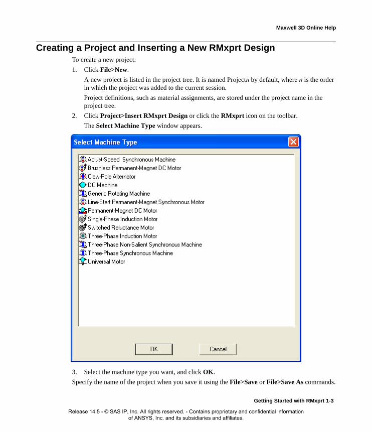
Creating a Project and Inserting a New RMxprt DesignTo create a new project:
1. Click File>New.
A new project is listed in the project tree. It is named Projectn by default, where n is the order in which the project was added to the current session.
Project definitions, such as material assignments, are stored under the project name in the project tree.
2. Click Project>Insert RMxprt Design or click the RMxprt icon on the toolbar.
The Select Machine Type window appears.
3. Select the machine type you want, and click OK.
Specify the name of the project when you save it using the File>Save or File>Save As commands.
Getting Started with RMxprt 1-3
Release 14.5 - © SAS IP, Inc. All rights reserved. - Contains proprietary and confidential information of ANSYS, Inc. and its subsidiaries and affiliates.

Maxwell 3D Online Help
Opening Existing RMxprt Projects and Saving as NewYou may also create new projects from existing ones, by saving them under new file names.
To create a new project from an existing one:
1. If you are already in the existing project, click File>Save As. The Save As window appears. (Otherwise, open the existing project you want to copy first.)
2. Enter a new name for the new project, and click Save.
The new project is now saved, with the same information as the existing project.
Opening RMxprt ProjectsOpen a previously saved project using the File>Open command.
1. Click File>Open.
The Open dialog box appears.
2. Use the file browser to find the RMxprt version 6 project file.
By default, files that can be opened or translated by RMxprt are displayed.
3. Select the file you want to open.
4. Click OK.
The project information appears in the project tree.
Opening Recent RMxprt ProjectsTo open a project you recently saved:
• Click the name of the project file at the bottom of the File menu.
Saving RMxprt ProjectsUse the File>Save As command to do the following:
• Save a new project.
• Save the active project with a different name or in a different location.
• Save the active project in another file format for use in another program.
Use the File>Save command to save the active project.
Related Topics
Saving a New Project
Saving the Active Project
Saving a Copy of a Project
Saving a New RMxprt Project1. Click File>Save As.
The Save As dialog box appears.
1-4 Getting Started with RMxprt
Release 14.5 - © SAS IP, Inc. All rights reserved. - Contains proprietary and confidential information of ANSYS, Inc. and its subsidiaries and affiliates.

Maxwell 3D Online Help
2. Use the file browser to find the directory where you want to save the file.
3. Type the name of the file in the File name box.
By default, all files will have the .mxwl extension.
4. Click Save.
RMxprt saves the project to the location you specified.
Related Topics
Saving the Active Project
Saving a Copy of a Project
Saving the Active RMxprt Project• Click File>Save.
RMxprt saves the project over the existing one.
Related Topics
Saving a New Project
Saving a Copy of a Project
Saving a Copy of an RMxprt ProjectTo save an existing, active project with a new name, a different file extension, or to a new location:
1. Click File>Save As.
2. Use the file browser to find the directory where you want to save the file.
3. Type the name of the file in the File name box.
4. Click Save.
RMxprt saves the project with the new name or file extension to the location you specified.
Related Topics
Saving a New Project
Saving the Active Project
Saving RMxprt Project Data AutomaticallyRMxprt stores recent actions you performed on the active project in an auto-save file in case a sud-den workstation crash or other unexpected problem occurs. The auto-save file is stored in the same directory as the project file and is named Projectn.rmpt.auto by default, where n is the order in which the project was added to the current session. RMxprt automatically saves all data for the project to the auto-save file, except solution data. By default, RMxprt automatically saves project data after every ten edits. An "edit" is any action you perform that changes data in the project or the
Warning Be sure to save machine models periodically. Saving frequently helps prevent the loss of your work if a problem occurs. Although RMxprt has an "auto-save" feature, it may not automatically save frequently enough for your needs.
Getting Started with RMxprt 1-5
Release 14.5 - © SAS IP, Inc. All rights reserved. - Contains proprietary and confidential information of ANSYS, Inc. and its subsidiaries and affiliates.

Maxwell 3D Online Help
design, including actions associated with project management, model creation, and solution analy-sis.
With auto-save activated, after a problem occurs, you can choose to re-open the original project file (Projectn.mxwl) in an effort to recover the solution data or to open the auto-save file.
To modify the auto-save settings:
1. Click Tools>Options>General Options.
The Options dialog box appears.
2. Under the Project Options tab, verify that Do Autosave is selected.
This option is selected by default.
3. In the Autosave interval box, enter the number of edits that you want to occur between automatic saves. By default, this option is set at 10.
4. Click OK to apply the specified auto-save settings.
Once the specified number of edits is carried out, a "model-only" save occurs. This means that RMxprt does not save solutions data or clear any undo/redo history.
When RMxprt auto-saves, an ".auto" extension is appended to the original project file name. For example, Project1.rmpt will automatically be saved as Projectn.mxwl.auto.
Related Topics
Recovering Project Data in an Auto-Save File
Recovering RMxprt Project Data in an Auto-Save File
Following a sudden workstation crash or other unexpected problem, you can recover the project data in its auto-save file.
To recover project data in an auto-save file, if RMxprt has unexpectedly crashed:
1. Launch RMxprt from your desktop.
2. Click File>Open,.
3. Select the original Projectn.rmpt project file for which you want to recover its Pro-jectn.rmpt.auto auto-save file.
The Crash Recovery window appears, giving you the option to open the original project file
Note Auto-save always increments forward; therefore, even when you undo a command, RMxprt counts it as an edit.
Warning When you close or rename a project, RMxprt deletes the auto-save file. RMxprt assumes that you have saved any desired changes at this point.
Warning When you recover a project's auto-save file you cannot recover any solutions data; recovering an auto-save file means you will lose any solutions data that existed in the original project file.
1-6 Getting Started with RMxprt
Release 14.5 - © SAS IP, Inc. All rights reserved. - Contains proprietary and confidential information of ANSYS, Inc. and its subsidiaries and affiliates.

Maxwell 3D Online Help
or the auto-save file.
4. Select Open project using autosave file to recover project data in the auto-save file, and then click OK. RMxprt replaces the original project file with the data in the auto-save file.
RMxprt immediately overwrites the original project file data with the auto-save file data, removing the results directory (solutions data) from the original project file as it overwrites to the auto-save file.
Related Topics
Saving Project Data Automatically
RMxprt FilesWhen you create any project in the Maxwell desktop, including an RMxprt project, it is given a .mxwl file extension and stored in the directory you specify. Any files related to that project are also stored in that directory.
Some common file and folder types are listed below:
Saving Project Notes in RMxprt You can save notes about a project, such as its creation date and a description of the device being modeled. This is useful for keeping a running log on the project.
To add notes to a project:
1. Click RMxprt>Edit Notes.
The Design Notes dialog box appears.
2. Click in the window and type your notes.
3. Click OK to save the notes with the current project.
To edit existing project notes:
1. Double-click the Notes icon in the project tree. The Design Notes window appears, where you can edit the project's notes.
2. Click OK to save any changes, or click Cancel to exit without saving edits.
Warning If you choose to recover the auto-save file, you cannot recover the original project file that has been overwritten; recovering data in an auto-save file is not reversible.
.mxwl Maxwell or RMxprt project.
project_name.mxwlresults Folder containing results data for a project.
design_name.results Folder containing results data for a design. This folder is stored in the project_name.mxwlresults folder.
design_name.asol Results data for a design. This file's contents may be empty if a solution is unavailable. This file is stored in the project_name.mxwlresults folder.
Getting Started with RMxprt 1-7
Release 14.5 - © SAS IP, Inc. All rights reserved. - Contains proprietary and confidential information of ANSYS, Inc. and its subsidiaries and affiliates.

Maxwell 3D Online Help
The RMxprt DesktopRMxprt is integrated within the Maxwell desktop. Consistent with the Maxwell desktop, the RMx-prt interface consists of 9 desktop components: a title bar, a menu bar, toolbars, a status bar, a proj-ect manager window, a properties window, a message manager window, a progress window, and a machine editor window. If user-defined rotor or stator slots are used in the design, a slot editor win-dow also displays when a rotor or stator slot is selected in the project tree. The project manager window, the properties window, the message manager window and the progress window are dock-able and resizable.
You can open multiple machine editor windows to display different parts at the same time. One can remain fixed on the winding, one on the diagram, and one on the main desktop window. To open a new window, click Window>New Window.
1-8 Getting Started with RMxprt
Release 14.5 - © SAS IP, Inc. All rights reserved. - Contains proprietary and confidential information of ANSYS, Inc. and its subsidiaries and affiliates.
Maxwell 3D Online Help
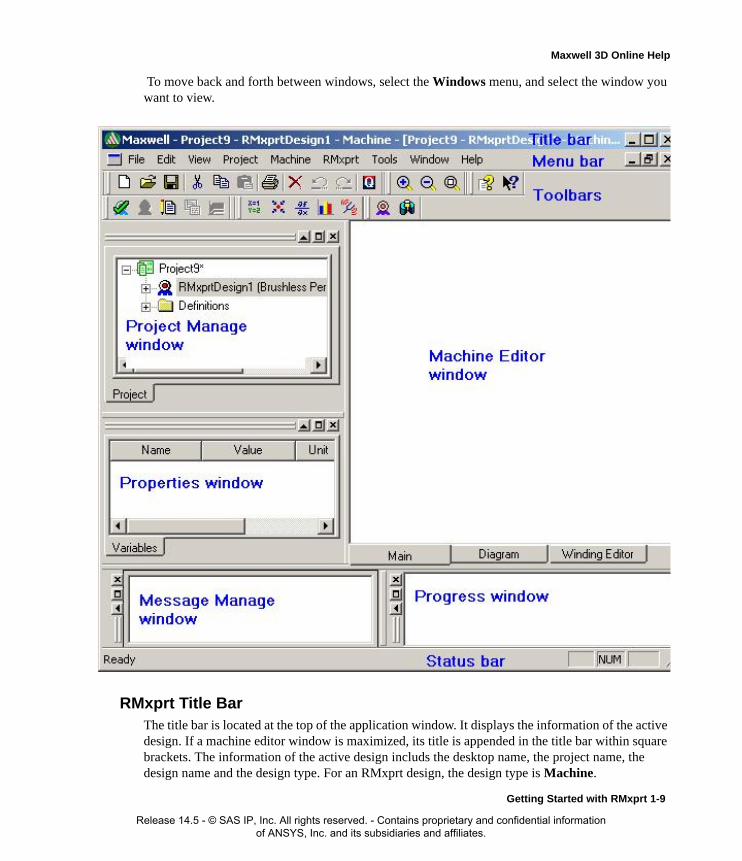
To move back and forth between windows, select the Windows menu, and select the window you want to view.
RMxprt Title BarThe title bar is located at the top of the application window. It displays the information of the active design. If a machine editor window is maximized, its title is appended in the title bar within square brackets. The information of the active design includs the desktop name, the project name, the design name and the design type. For an RMxprt design, the design type is Machine.
Getting Started with RMxprt 1-9
Release 14.5 - © SAS IP, Inc. All rights reserved. - Contains proprietary and confidential information of ANSYS, Inc. and its subsidiaries and affiliates.

Maxwell 3D Online Help
Working with the RMxprt Menu BarThe menu bar enables you to perform all Maxwell, ePhysics, and/or RMxprt tasks, depending on the software you purchased. Such tasks include managing project files, customizing the desktop, drawing objects, and setting and modifying all project parameters.
RMxprt contains the following menus, which appear at the top of the desktop:
Related Topics
Getting Help
File menu Use the File menu commands to manage RMxprt project files and printing options.
Edit menu Use the Edit menu commands to modify properties in the active design, manage designs in one or more projects, delete projects, and undo and redo actions.
View menu Use the View menu commands to display or hide desktop components, and change the machine editor window view.
Project menu Use the Project menu commands to add a Maxwell 3D, Maxwell2D, or RMxprt design to the active project, analyze all designs of the active project, and define project variables and datasets.
Machine menu Use the Machine menu to work with the machine data, such as edit winding layout, edit wire size, and set dimension unit for the active editor window.
RMxprt menu Use the RMxprt menu commands to validate design input data, analyze designs, set up parameters, add analysis setups, set up Optimetrics, post process solutions, and other design tasks.
Tools menu Use the Tools menu to modify the active project's material library, arrange the material libraries, run and record scripts, update project definitions from libraries, display options, customize the desktop's toolbars, and modify many of the software's default settings.
Window menu Use the Window menu commands to rearrange the application windows and toolbar icons.
Help menu Use the Help menu commands to access the online help system and view the current software version information.
1-10 Getting Started with RMxprt
Release 14.5 - © SAS IP, Inc. All rights reserved. - Contains proprietary and confidential information of ANSYS, Inc. and its subsidiaries and affiliates.

Maxwell 3D Online Help
Working with the RMxprt Shortcut MenusA variety of shortcut menus — menus that appear when you right-click a selection — are available in the toolbars area of the desktop, in the Machine Editor window, in the Project Manager win-dow, in the Properties window, and in the Message Manager window.
Shortcut Menu in the Toolbars AreaUse the shortcut menu in the toolbars area of the desktop to show or hide windows or toolbars, and customize the toolbars.
To access the shortcut menu in the toolbars area:
• Right-click in the toolbars area at the top of the desktop.
A check box appears next to a command if the item is visible. For example, if a check box appears next to the Project Manager command, then the Project Manager window is currently visible on the desktop.
Click Customize to open the Customize dialog box, which enables you to modify the toolbar set-tings on the desktop.
Shortcut Menus in the Project Manager Window
Each node, or item, in the project tree has a shortcut menu.
To access the shortcut menu in the Project Manager window, for a particular node:
• Select a node or item.
• Right-click in the Project Manager window.
In the toolbars area Use the shortcut menu in the toolbars area of the desktop to show or hide windows or toolbars, and customize the toolbars.
In Machine Editor window
Use the shortcut menu in the Machine Editor window to edit winding layout, display or hidden coil connection, change the view, and copy to Clipboard.
In the Slot Editor window Use the shortcut menu in the Slot Editor window to insert, append, modify, and remove slot segments.
In the Project Manager window
Use the shortcut menus in the Project Manager window (or the project tree) to manage project files and design properties; these commands duplicate menu commands at the top of the screen.
In Properties window Use the shortcut menus in the Properties window to edit (cut, copy, paste or delete) property values.
In Message Manager window
Use the shortcut menus in the Message Manager window to clear, copy message, or see message details.
Note Most of the commands on the shortcut menus are also available on the menu bar.
Getting Started with RMxprt 1-11
Release 14.5 - © SAS IP, Inc. All rights reserved. - Contains proprietary and confidential information of ANSYS, Inc. and its subsidiaries and affiliates.

Maxwell 3D Online Help
Working with the RMxprt ToolbarsThe toolbar buttons and shortcut pull-down lists act as shortcuts for executing various commands. You can rearrange the position of the various toolbars.
• To execute a command, click a toolbar button or click a selection on the shortcut pull-down list.
• To display a brief description of the toolbar button, move the pointer over the button.
• To relocate a toolbar, click on the left edge of a toolbar and drag it to new location..
Undoing RMxprt Commands
Use the Undo command on the Edit menu to cancel, or undo, the last action you performed on the active project or design.
1. In the Project Manager window, do one of the following:
• To undo the last action you performed on the active project, such as inserting a design, click the project icon.
• To undo the last action you performed on the active design, click the design icon.
2. Click Edit>Undo.
Your last action is now undone.
Related Topics
Redoing Commands
Redoing RMxprt Commands
Use the Redo command on the Edit menu to reapply, or redo, the last action that was canceled, or undone. You can redo a canceled action related to project management, model creation, and post-processing.
1. In the Project Manager window, do one of the following:
• To redo the last action you canceled on the active project, such as inserting a design or adding project variables, click the project icon.
• To redo the last action you canceled on the active design, such as drawing an object or deleting a field overlay plot, click the design icon.
2. Click Edit>Redo.
Hint To modify the toolbars on the desktop, click Tools>Customize. To display all toolbar buttons, click the Reset All button in the Customize window.
Note You cannot undo an analysis that you have performed on a model, that is, the RMxprt>Analyze command.
Note When you save a project, RMxprt always clears the entire undo/redo history for the project and its designs.
1-12 Getting Started with RMxprt
Release 14.5 - © SAS IP, Inc. All rights reserved. - Contains proprietary and confidential information of ANSYS, Inc. and its subsidiaries and affiliates.

Maxwell 3D Online Help
Your last canceled action is now reapplied.
Related Topics
Undoing Commands
Working with the RMxprt Status BarThe status bar is located at the bottom of the application window. It displays information about the where mouse is pointed.
To display or hide the status bar:
• Click View>Status Bar.
A check box appears next to this command if the status bar is visible.
Working with the RMxprt Machine Editor WindowsYou can open multiple machine editor windows in RMxprt. One can remain fixed on the Winding Editor, one on the Diagram tab, and one on the Main tab. To open a new window, click Win-dow>New Window. To move back and forth between windows, select the Windows menu, and select the window you want to view.
You can cascade all Machine Editor windows, tile them horizontally or vertically. You can maxi-mize, minimize or close a Machine Editor window by clicking the relevant button on the right-top corner of the window. If no Machine Editor window is displayed, you can use RMxprt>Machine Editor to bring one window up. When only one Machine Editor window is maximized, the win-dow title is displayed within square brackets in the Title Bar of the main application window.
As you enter appropriate property values, the Machine Editor window dynamically updates the rotor, stator, slots, and windings in the Main, Diagram and Winding Editor tabs. As you provide winding information, the Winding Editor tab displays a table of values.
Related Topics
Setting the Window View
Note When you save a project, RMxprt always clears the entire undo/redo history for the project and its designs.
Getting Started with RMxprt 1-13
Release 14.5 - © SAS IP, Inc. All rights reserved. - Contains proprietary and confidential information of ANSYS, Inc. and its subsidiaries and affiliates.

Maxwell 3D Online Help
Printing in RMxprt
Setting the Window View
To fit the entire diagram in the window:
• Click View>Fit All.
To zoom into the diagram in the window:
• Click View>Zoom In.
To zoom out of the diagram in the window:
• Click View>Zoom Out.
Printing in RMxprt The printing commands enable you to print the display in the active window.
To print the project:
1. Click File>Print.
The Print dialog box appears.
2. You can change the print quality (a higher dpi produces a higher quality print but takes more time and printer memory), or you can send the output to a .prn file.
3. Do one of the following:
• Click OK to print the project.
• Click Cancel to dismiss the window without printing.
• Click Properties to define printer settings.
1-14 Getting Started with RMxprt
Release 14.5 - © SAS IP, Inc. All rights reserved. - Contains proprietary and confidential information of ANSYS, Inc. and its subsidiaries and affiliates.

Maxwell 3D Online Help
Working with the RMxprt Project ManagerThe Project Manager window displays the open project's structure, which is referred to as the project tree. The Project Manager window displays details about all projects open in the Maxwell Desktop, regardless of type.
To show or hide the Project Manager window, do one of the following:
• Click View>Project Manager.
A check box appears next to this command if the Project Manager window is visible.
• Right-click in the toolbars area on the desktop, and then click Project Manager on the short-cut menu.
A check box appears next to this command if the Project Manager window is visible.
Related Topics
Working with the RMxprt Project Tree
Shortcut Menus in the Project Manager Window
Working with the RMxprt Project TreeThe project tree is located in the Project Manager window and contains details about all open projects. The top node listed in the project tree is the project name. It is named Projectn by default, where n is the order in which the project was added to the current session of the Maxwell Desktop. Expand the project icon to view all designs and material definitions belonging to the project. For RMxprt projects, the project tree shows where you can select each portion of the machine to open the corresponding tab sheet in the Properties window. The project tree lists options for the general motor characteristics, the stator, the rotor, and other options such as winding data or commutating data. The specific options depend on the machine type you have selected.
Related Topics
Viewing RMxprt Design Details
Automatically Expand the Project Tree
Setting the RMxprt Project Tree to Expand Automatically
You can set the project tree to automatically expand when an item is added to a project.
1. Click Tools>Options>General Options.
The Options dialog box appears.
2. Click the Project Options tab.
3. Under Additional Options, select Expand Project Tree on Insert.
4. Click OK.
Viewing RMxprt Design Details
Once you insert an RMxprt design into a project, it is listed as the second-level node in the project tree. It is named RMxprtDesignn by default, where n is the order in which the design was added to the project. Expand the design icon in the project tree to view specific data about the model.
Getting Started witn RMxprt 1-15
Release 14.5 - © SAS IP, Inc. All rights reserved. - Contains proprietary and confidential information of ANSYS, Inc. and its subsidiaries and affiliates.

Maxwell 3D Online Help
The RMxprtDesignn node contains the following project details:
Working with the RMxprt Properties WindowThe Properties window displays the attributes, or properties, of an item selected in the project tree-and enables you to edit an item's properties. The properties, and the ability to edit them in the Prop-erties window vary depending on the type of item selected. The tabs available in the Properties window also vary depending the selection.
Single clicking on an item in the Machine section of the project tree displays a docked Properties window located under the project tree. A horizontal scroll bar lets you adjust the view of the prop-erties if necessary. Changes to values in the docked properties window apply immediately to the selected object.
Double-clicking on an item in the Machine section of the project tree opens a floating Properties window. The floating window can be moved for convenience in viewing the RMxprt Machine Editor window. Some objects have tabs on the window to control the properties displayed. Changes to values in the floating window are not applied until you click the OK button.
Related Topics
Showing and Hiding the Properties Window
Setting the Properties Window to Open Automatically
Showing and Hiding the RMxprt Properties Window
To show or hide the Properties window on the desktop, do one of the following:
• Click View>Property Window.
A check box appears next to this command if the Properties window is visible.
• Right-click in the toolbars area at the top of the desktop, and then click Properties on the shortcut menu.
A check box appears next to this command if the Properties window is visible.
Machine Allows you to specify parameters for various aspects of the machine. A whole or part geometry will be drawn in the Main tab of the Machine Editor window (based on the values you enter).
Analysis Displays the solution setups for an RMxprt design. A solution setup specifies how RMxprt computes the solution.
Optimetrics Displays any Optimetrics setups added to an RMxprt design.
Results Displays any post-processing reports that have been generated.
Note To edit a project's design details:
• In the project tree, double-click the design setup icon that you want to edit.
A dialog box appears with that setup's parameters, which you can then edit.
1-16 Getting Started with RMxprt
Release 14.5 - © SAS IP, Inc. All rights reserved. - Contains proprietary and confidential information of ANSYS, Inc. and its subsidiaries and affiliates.

Maxwell 3D Online Help
Working with the RMxprt Progress WindowThe Progress window monitors a simulation while it is running.
To display or hide the Progress window on the desktop, do one of the following:
• Click View>Progress Window.
A check box appears next to this command if the Progress window is visible.
• Right-click in the toolbars area at the top of the desktop, and then click Progress on the short-cut menu.
A check box appears next to this command if the Progress window is visible.
Working with the RMxprt Message ManagerThe Message Manager displays messages associated with a project's development, such as error messages about the design's setup or informational messages about the progress of an analysis.
To display or hide the Message Manager window on the desktop, do one of the following:
• Click View>Message Manager.
• Right-click in the toolbars area at the top of the desktop, and then click Message Manager on the shortcut menu.
A check box appears next to this command if the Message Manager is visible.
Related Topics
Clearing Messages for the RMxprt Project
Clearing Messages for the RMxprt Model
Copying Messages in RMxprt
Clearing Messages for the RMxprt ProjectYou can clear all the messages for a particular project.
To clear messages:
1. Right-click the project# in the Message Manager.
A pop-up appears.
2. Click Clear messages for Project#.
Clearing Messages for the RMxprt ModelYou can clear all the messages for a particular model.
To clear messages:
1. Right-click the RMxprtDesign# in the Message Manager.
A pop-up appears.
2. Click Clear messages for RMxprtDesign#.
Copying Messages in RMxprt You can copy all the messages for a particular project.
Getting Started witn RMxprt 1-17
Release 14.5 - © SAS IP, Inc. All rights reserved. - Contains proprietary and confidential information of ANSYS, Inc. and its subsidiaries and affiliates.

Maxwell 3D Online Help
To copy messages:
1. Right-click in the Message Manager.
A pop-up appears.
2. Click Copy messages to clipboard.
1-18 Getting Started with RMxprt
Release 14.5 - © SAS IP, Inc. All rights reserved. - Contains proprietary and confidential information of ANSYS, Inc. and its subsidiaries and affiliates.

Maxwell 3D Online Help
Quick Start for RMxprtThis section briefly introduces how to enter the environment of the software RMxprt and quick mastering its main functions by providing a simple example.
The basic process flow chart is shown below.
RMxprt Example Part 1: Create a New ProjectTo create a new project:
1. Start Maxwell from the desktop.
2. Click File>New from the menu bar.
This creates a new project folder in the project window with the default name of Projectn.
RMxprt Example Part 2: Select a MachineTo select a machine to insert into the new project:
1. Click Project>Insert RMxprt Design or click the RMxprt icon in the tool bar.
This displays the Select Machine Type window.
2. From the list of machine types, for this example, select Brushless Permanent Magnet DC Motor and click OK.
Create a new Project
Select the machine type.
Input design data.
Create a Maxwell 2D Project for electromagnetic field analyses
Create an electric machine model for Simplorer System Simulation
Analyze the design.
Create Reports and View output characteristics curves.
Getting Started with RMxprt 1-19
Release 14.5 - © SAS IP, Inc. All rights reserved. - Contains proprietary and confidential information of ANSYS, Inc. and its subsidiaries and affiliates.

Maxwell 3D Online Help
This closes the window and inserts the Brushless Permanent Magnet DC Motor design in the project.
Continue to Part 3 of the example to Input Design Data.
RMxprt Example Part 3: Input Design DataIn this part of the example, you provide values for the design and for various parts.
1. Click the + symbol by the RMxprt:Designn icon in the project tree to view the design hierar-chy.
This displays the Machine Icon.
2. Double-click the icon to view the Machine Properties window.
Set the values as indicated below.
3. Click OK to close the Machine properties window.
4. Click the + symbol by the Machine icon to view the design hierarchy of the motor.
5. Double-click the Circuit icon to view the Circuit properties window.
Machine Type Brushless Permanent Magnet DC Motor
Number of Poles Set this to 4
Rotor Position Set to Inner
Frictional Loss Set this to 11 (Frictional and wind loss is typically within the range of 1%~3% of the rated output power, in this example, 2% is estimated.) This value is referred to the given Reference Speed. The frictional loss at the computed rated speed will be modified if the computed rated speed is different from the given rated speed.
Wind Loss 0
Reference Speed Set this to 1500
Control Type DC
Circuit Type Set this to C2.
Click the button to display the Select Circuit Type window.
Select the C2 button, and OK to close the window.
1-20 Getting Started with RMxprt
Release 14.5 - © SAS IP, Inc. All rights reserved. - Contains proprietary and confidential information of ANSYS, Inc. and its subsidiaries and affiliates.
Maxwell 3D Online Help
Set the values as indicated below.
6. Click OK to close the circuit properties window.
7. Double-click the Stator icon to view the Stator properties window.
Set the values as shown below.
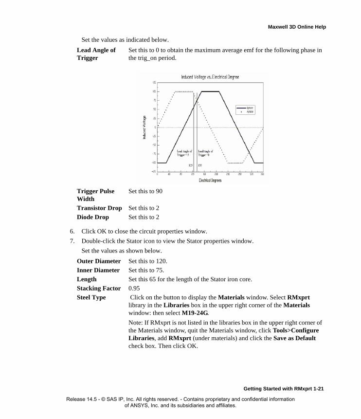
Lead Angle of Trigger
Set this to 0 to obtain the maximum average emf for the following phase in the trig_on period.
Trigger Pulse Width
Set this to 90
Transistor Drop Set this to 2
Diode Drop Set this to 2
Outer Diameter Set this to 120.
Inner Diameter Set this to 75.
Length Set this 65 for the length of the Stator iron core.
Stacking Factor 0.95
Steel Type Click on the button to display the Materials window. Select RMxprt library in the Libraries box in the upper right corner of the Materials window: then select M19-24G.
Note: If RMxprt is not listed in the libraries box in the upper right corner of the Materials window, quit the Materials window, click Tools>Configure Libraries, add RMxprt (under materials) and click the Save as Default check box. Then click OK.
Getting Started with RMxprt 1-21
Release 14.5 - © SAS IP, Inc. All rights reserved. - Contains proprietary and confidential information of ANSYS, Inc. and its subsidiaries and affiliates.
Maxwell 3D Online Help
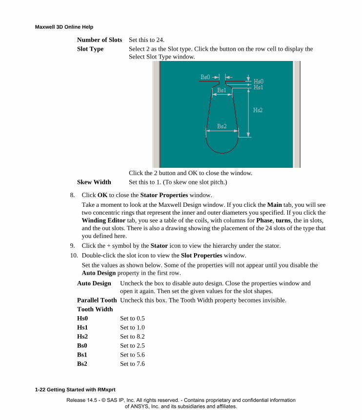
8. Click OK to close the Stator Properties window.
Take a moment to look at the Maxwell Design window. If you click the Main tab, you will see two concentric rings that represent the inner and outer diameters you specified. If you click the Winding Editor tab, you see a table of the coils, with columns for Phase, turns, the in slots, and the out slots. There is also a drawing showing the placement of the 24 slots of the type that you defined here.
9. Click the + symbol by the Stator icon to view the hierarchy under the stator.
10. Double-click the slot icon to view the Slot Properties window.
Set the values as shown below. Some of the properties will not appear until you disable the Auto Design property in the first row.
Number of Slots Set this to 24.
Slot Type Select 2 as the Slot type. Click the button on the row cell to display the Select Slot Type window.
Click the 2 button and OK to close the window.
Skew Width Set this to 1. (To skew one slot pitch.)
Auto Design Uncheck the box to disable auto design. Close the properties window and open it again. Then set the given values for the slot shapes.
Parallel Tooth Uncheck this box. The Tooth Width property becomes invisible.
Tooth Width
Hs0 Set to 0.5
Hs1 Set to 1.0
Hs2 Set to 8.2
Bs0 Set to 2.5
Bs1 Set to 5.6
Bs2 Set to 7.6
1-22 Getting Started with RMxprt
Release 14.5 - © SAS IP, Inc. All rights reserved. - Contains proprietary and confidential information of ANSYS, Inc. and its subsidiaries and affiliates.
Maxwell 3D Online Help
11. Click OK to close the Slot Properties window.
12. Double-click the stator Winding icon to view the Winding Properties window.
Set the values as shown below.
Winding tab Winding Layers
Winding Type Set this to 2, "Whole Coiled."
Parallel Branches Select 1 for the number of parallel-connected branches, i.e. the coils in all the slots per phase are in series-connected.
Conductors per Slot
Set this to 60 for the number of conductors per slot, i.e. the number of turns per coil is equal to 30 for double-layer winding.
Coil Pitch Set this to 5. For this example, full pitch = 24 slots /4 poles = 6. This example uses short coil pitch, 5, i.e. a coil
spans from slot 1 to slot 6.
Number of Strands Select 1 for the number of strands (or number of wires per conductor).
Wire Wrap Select 0. This is the total thickness of double side wire insulation. The input value 0 means that RMxprt will automatically check into the wire gauge library for the wrap thickness relevant to the wire gauge. Different manufacturers produce different Wire Wrap Thickness for electromagnetic wire. Typically, Wire Wrap Thickness for electromagnetic wire is 7~10% of Wire Diameter.
Wire Size Click on the Properties field to display the Wire Size window and select AUTO for automatic design of wire gauge. Wire Size will be set to 0 in the Wire Size window. This example relies on RMxprt to automatically select the optimum diameter and the gauge code for electromagnetic wire.
End/Insulation tab
Input Half-turn Length
Uncheck this box.
Half Turn Length This item is not shown if Input Half Turn Length is unchecked.
Getting Started with RMxprt 1-23
Release 14.5 - © SAS IP, Inc. All rights reserved. - Contains proprietary and confidential information of ANSYS, Inc. and its subsidiaries and affiliates.

Maxwell 3D Online Help
13. Click OK to close the stator Winding Properties window.
14. Click Machine>Wiiding>Connect All Coils.
The Winding tab in the main window shows all coils connected.
15. Double-click the Rotor Icon to view the Rotor Properties window.
Set the values as shown below.
End Adjustment Set this to 0 for the linear overhang of the end part of the coil out of the iron core as shown below. In this example, the coil turns immediately at the slot opening, therefore input 0.
Base Inner Radius 0
Tip Inner Diameter 0
End Clearance 0
Slot Liner Set this to 0.3 for the single side thickness of slot insulation.
Wedge Thickness 0
Layer Insulation 0
Limited Fill Factor 0.75
Outer Diameter Set this to 74.0. This is the Stator inner diameter - 2* AirGap.
Inner Diameter Input 26 for the inner diameter of the rotor core. This is also the diameter to match the shaft
Length Input 65 for the length of the rotor core. In this example, the lengths of the iron cores of the stator and the rotor are the same.
1-24 Getting Started with RMxprt
Release 14.5 - © SAS IP, Inc. All rights reserved. - Contains proprietary and confidential information of ANSYS, Inc. and its subsidiaries and affiliates.

Maxwell 3D Online Help
16. Click OK to close the Rotor Properties window.
17. Click the + symbol by the Rotor icon to open the project hierarchy under the rotor.
18. Double-click the Pole icon to view the Pole Properties window.
Steel Type Select M19-24 for the brand of the silicon-steel sheet for the rotor. In this example, the laminations are punched together on the same sheet; therefore, the brands of the silicon-steel sheet and the stacking factors are the same for the stator and the rotor.
Stacking Factor Input 0.95.
Pole Type Select 1. Click on the button on the Pole Type field to display the Select Pole Type window.
Click the 1 button and OK to close the window.
Getting Started with RMxprt 1-25
Release 14.5 - © SAS IP, Inc. All rights reserved. - Contains proprietary and confidential information of ANSYS, Inc. and its subsidiaries and affiliates.

Maxwell 3D Online Help
Set the values as shown below.
1-26 Getting Started with RMxprt
Release 14.5 - © SAS IP, Inc. All rights reserved. - Contains proprietary and confidential information of ANSYS, Inc. and its subsidiaries and affiliates.

Maxwell 3D Online Help
Embrace Input 0.7. Embrace of the rotor represents the ratio of the rotor central angle corresponding to the arc length along the rotor surface of an arched permanent-magnetic piece to the rotor central angle corresponding to a rotor pole. In a four pole machine with Embrace, 1, each arched permanent-magnetic piece covers 90 mechanical degrees along the rotor surface. Similarly, Embrace 0.667 means 60 mechanical degrees of the coverage of the magnet as shown in the figure.
Getting Started with RMxprt 1-27
Release 14.5 - © SAS IP, Inc. All rights reserved. - Contains proprietary and confidential information of ANSYS, Inc. and its subsidiaries and affiliates.
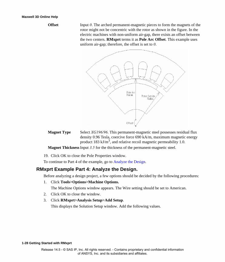
Maxwell 3D Online Help
19. Click OK to close the Pole Properties window.
To continue to Part 4 of the example, go to Analyze the Design.
RMxprt Example Part 4: Analyze the Design.Before analyzing a design project, a few options should be decided by the following procedures:
1. Click Tools>Options>Machine Options.
The Machine Options window appears. The Wire setting should be set to American.
2. Click OK to close the window.
3. Click RMxprt>Analysis Setup>Add Setup.
This displays the Solution Setup window. Add the following values.
Offset Input 0. The arched permanent-magnetic pieces to form the magnets of the rotor might not be concentric with the rotor as shown in the figure. In the electric machines with non-uniform air-gap, there exists an offset between the two centers. RMxprt terms it as Pole Arc Offset. This example uses uniform air-gap; therefore, the offset is set to 0.
Magnet Type Select XG196/96. This permanent-magnetic steel possesses residual flux density 0.96 Tesla, coercive force 690 kA/m, maximum magnetic energy product 183 kJ/m3, and relative recoil magnetic permeability 1.0.
Magnet Thickness Input 3.5 for the thickness of the permanent-magnetic steel.
1-28 Getting Started with RMxprt
Release 14.5 - © SAS IP, Inc. All rights reserved. - Contains proprietary and confidential information of ANSYS, Inc. and its subsidiaries and affiliates.

Maxwell 3D Online Help
4. Close the dialog to save the Setup.
5. Click RMxprt>Validation Check to ensure that all values have been set.
If any items do not pass validation, use the diagnostic information in the Message Window to resolve any issues.
6. When the design has been validated, click RMxprt>Analyze All.
The progress of the analysis is shown in the Progress window.
To continue to Part 5 of the example, go to Create Reports and View Output.
RMxprt Example Part 5: Create Reports and View OutputAfter you have run an analysis, you can view the solution data.
1. Click RMxprt>Results>Solution Data.
This opens the Solutions window with the Solutions tab selected, and the Full Load Operation Data displayed. The Solutions window contains tabs for the following:
• Solution Data - the Data field in the Solutions window is a drop down menu from which you can select the following:
• Full Load Operation
• Material Consumption
• No Load Operation
• Permanent Magnet
• Rotor Data
• Stator Slot
• Stator Winding
• Steady State Parameters
• Parameter
• Design Sheet
• Curves - Selecting the Curves tab lets you view pre-defined graphs.
2. With the Solution tab selected, select Stator Winding as the Data selected.
Except for a few data corresponding to the wire gauge, this part of data should be the same as the data input in the Stator Winding Properties window. Since automatic design function for
Load Type Const Power
Rated Output Power
0.55 kW
Rated Voltage 220
Rated Speed 1500
Operating Temperature
75c
Getting Started with RMxprt 1-29
Release 14.5 - © SAS IP, Inc. All rights reserved. - Contains proprietary and confidential information of ANSYS, Inc. and its subsidiaries and affiliates.

Maxwell 3D Online Help
the wire gauge is selected in the input, RMxprt calculates the following data:
The electromagnetic wire with Wire Diameter of 0.8118 is equivalent to AWG 20. Stator Slot Fill Factor represents the percentage of occupation of the slot area, i.e. the ratio of the total square sectional area of wires (including Wire Wrap Thickness) in a slot to the total slot area less the slot insulation.
a. Now that Wire Diameter of the electromagnetic wire is calculated by RMxprt, you can open the Winding Properties window and specify the value.
b. For Wire Size, open the Wire Size selection window, select 0.8118 for the electromag-netic wire diameter, which corresponds to 20 for the wire gauge.
c. In the slot Wire Wrap field, input 0.08 for the insulation thickness of the electromagnetic wire.
d. Click OK to close the properties window.
e. Click RMxprt>Analyze All.
After the second analysis is completed, click RMxprt>Results>Solution Data to view the effect of Wire Wrap Thickness of the electromagnetic wire on Stator Slot Fill Factor.
3. In the Solutions window, change the Data selection to Rotor Data.
The Rotor data is displayed.
Here most of the data is the same as input in the Rotor Pole properties window. The only dif-ference is that the Pole Arc radius replaces Pole Arc Offset and, in addition to Mechanical Pole Embrace which is input based on the physical geometry, Electrical Pole Embrace is also given. Electrical Pole Embrace is calculated by the ratio of the average magnetic flux density to the maximum magnetic flux density according to the magnetic flux density distribu-tion along the air-gap.
4. In the Solutions window, change the Data selection to Permanent Magnet.
Wire Diameter (mm):
0.8118 for the diameter of the electromagnetic wire.
Wire Wrap Thickness (mm):
0 for the insulation thickness of the electromagnetic wire. Because input wire wrap is 0, RMxprt picks it up from the selected wire library (American wire), but it still 0 based on the wire wrap data in the library.
Stator Slot Fill Factor (%):
61.4557.
Wire Diameter (mm):
0.8118.
Wire Wrap Thickness (mm):
0.08.
Stator Slot Fill Factor (%):
74.165.
1-30 Getting Started with RMxprt
Release 14.5 - © SAS IP, Inc. All rights reserved. - Contains proprietary and confidential information of ANSYS, Inc. and its subsidiaries and affiliates.
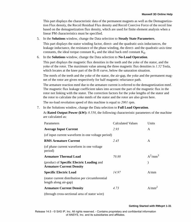
Maxwell 3D Online Help
This part displays the characteristic data of the permanent magnets as well as the Demagnetiza-tion Flux density, the Recoil Residual Flux density and Recoil Coercive Force of the recoil line based on the demagnetization flux density, which are used for finite element analysis when a linear PM characteristics must be specified.
5. In the Solutions window, change the Data selection to Steady State Parameters.
This part displays the stator winding factor, direct- and the quadratic-axis inductances, the leakage inductance, the resistance of the phase winding, the direct- and the quadratic-axis time constants, the ideal torque constant KT and the ideal back emf constant KE.
6. In the Solutions window, change the Data selection to No-Load Operation.
This part displays the magnetic flux densities in the teeth and the yoke of the stator, and the yoke of the rotor. The maximum value among the three magnetic flux densities is 1.52 Tesla, which locates at the knee part of the B-H curve, below the saturation situation.
The mmfs of the teeth and the yoke of the stator, the air-gap, the yoke and the permanent mag-net of the rotor are given respectively for half magnetic reluctance path.
The armature reaction mmf due to the armature current is referred to the demagnetization mmf. The magnetic flux leakage coefficient takes into account the part of the magnetic flux in the rotor not linking with the stator. The correction factors for the yoke lengths of the stator and the rotor to calculate the yoke mmfs of the stator and the rotor are also given here.
The no-load revolution speed of this machine is equal to 2001 rpm.
7. In the Solutions window, change the Data selection to Full Load Operation.
At Rated Output Power (kW): 0.550, the following characteristic parameters of the machine are calculated as:
Parameters Calculated Values Units
Average Input Current 2.93 A
(of input current waveform in one voltage period)
RMS Armature Current 2.45 A
(of phase current waveform in one voltage period)
Armature Thermal Load 70.88 A2/mm3
(product of Specific Electric Loading and Armature Current Density
)
Specific Electric Load 14.97 A/mm
(stator current distribution per circumferential length along air-gap)
Armature Current Density 4.73 A/mm2
(through cross-sectional area of stator wire)
Getting Started with RMxprt 1-31
Release 14.5 - © SAS IP, Inc. All rights reserved. - Contains proprietary and confidential information of ANSYS, Inc. and its subsidiaries and affiliates.

Maxwell 3D Online Help
8. In the Solutions window, select the Design Sheet tab, and scroll down to Winding Arrange-ment.
This is the layout and the arrangement of the whole two-phase winding of phases A and B, and the short coil pitch factor 5 is taken into account.
Frictional and Wind Loss 11.46 W
(at computed Rated Speed)
Iron-Core Loss 20.24 W
(due to loss curves of stator and rotor iron-core materials)
Armature Copper Loss 53.87 W
(stator winding ohmic loss)
Transistor Loss 9.32 W
(transistor switching loss)
Diode Loss 0.69 W
(diode power consumption)
Total Loss 95.6 W
(sum of above losses)
Output Power 550 W
(the rated operating point is derived based on Output Power)
Input Power 645.6 W
(product of Rated Voltage and Average Input Current)
Efficiency 85.2 %
(ratio of Output Power to Input Power)
Rated Speed 1562 rpm
(at Rated Output Power)
Rated Torque 3.36 Nm
(at Rated Output Power)
Locked-Rotor Torque 32.3 Nm
(starting torque at zero revolution speed)
Locked-Rotor Current 47.6 A
(starting current at zero revolution speed)
1-32 Getting Started with RMxprt
Release 14.5 - © SAS IP, Inc. All rights reserved. - Contains proprietary and confidential information of ANSYS, Inc. and its subsidiaries and affiliates.
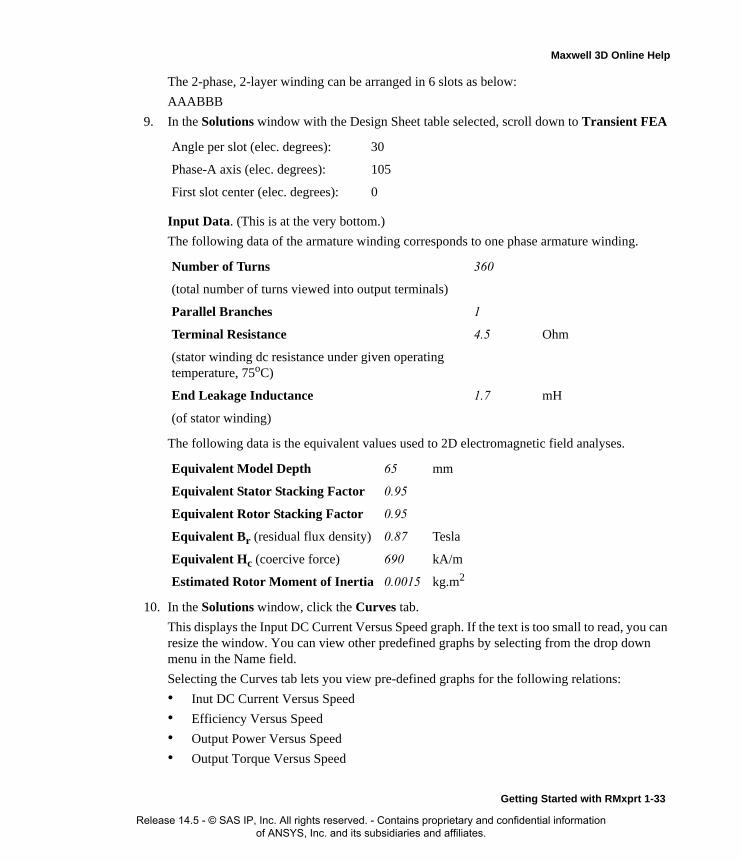
Maxwell 3D Online Help
The 2-phase, 2-layer winding can be arranged in 6 slots as below:
AAABBB
9. In the Solutions window with the Design Sheet table selected, scroll down to Transient FEA
Input Data. (This is at the very bottom.)
The following data of the armature winding corresponds to one phase armature winding.
The following data is the equivalent values used to 2D electromagnetic field analyses.
10. In the Solutions window, click the Curves tab.
This displays the Input DC Current Versus Speed graph. If the text is too small to read, you can resize the window. You can view other predefined graphs by selecting from the drop down menu in the Name field.
Selecting the Curves tab lets you view pre-defined graphs for the following relations:
• Inut DC Current Versus Speed
• Efficiency Versus Speed
• Output Power Versus Speed
• Output Torque Versus Speed
Angle per slot (elec. degrees): 30
Phase-A axis (elec. degrees): 105
First slot center (elec. degrees): 0
Number of Turns 360
(total number of turns viewed into output terminals)
Parallel Branches 1
Terminal Resistance 4.5 Ohm
(stator winding dc resistance under given operating temperature, 75oC)
End Leakage Inductance 1.7 mH
(of stator winding)
Equivalent Model Depth 65 mm
Equivalent Stator Stacking Factor 0.95
Equivalent Rotor Stacking Factor 0.95
Equivalent Br (residual flux density) 0.87 Tesla
Equivalent Hc (coercive force) 690 kA/m
Estimated Rotor Moment of Inertia 0.0015 kg.m2
Getting Started with RMxprt 1-33
Release 14.5 - © SAS IP, Inc. All rights reserved. - Contains proprietary and confidential information of ANSYS, Inc. and its subsidiaries and affiliates.

Maxwell 3D Online Help
• Cogging Torque in Two Teeth
• Induced Coil Voltages at Rated Speed
• Air-Gap Flux Density
• Induced Winding Phase Voltage at Rated Speed
• Winding Currents Under Load
• Phase Voltage Under Load
You can also create additional plots with multiple curves.
11. For example, click RMxprt>Results>Create Report.
This displays the Create Report dialog box. Click OK to display the Traces window.
12. In the Traces window, select Input DC Current and Efficiency vs Speed, and click the Add Trace button. Then select Output Torque.
13. These traces appear in the Traces field. Click Done to close the Traces window and display the combined graph.
To continue to part Six of the example, go to Output Design Data.
RMxprt Example Part 6: Output Design DataTo export the model for Maxwell 2D Analysis:
1. Click RMxprt>Set Export Options.
This opens the Export Options window.
Periodic According to the geometric symmetry, the structure of electric machine can be divided into several periods. The four pole electric machine in this example has a whole slot number per pole per phase, therefore, it can be divided into four periods. Choose the smaller period to shorten the run-time for 2D Maxwell analyses.
Difference The angular displacement from the rotor to the stator in electric degrees.
Band Arc The air-gap is divided uniformly along the circumference. Band Arc is the central angle corresponding to each division. The effective range of its value is between 1o to 5o, the default value is 3o. In 2D electromagnetic field analysis to the torque with 2D Maxwell, the value of Band Arc is sensitive. The lower the value, the finer the air-gap meshes, the more accurate the torque calculation, but longer the computation time in order.
Teeth to Teeth If you select this box, the central lines of the rotor teeth or the rotor magnet poles coincide with the periodic dividing lines, otherwise, the central lines of the rotor slots or the interpole lines of the rotor magnet poles coincide with the periodic dividing line. Nevertheless, the central lines of the stator teeth always coincide with the periodic dividing lines.
Design Sheet This lets you specify an Excel Spreadsheet template for a customized design sheet.
1-34 Getting Started with RMxprt
Release 14.5 - © SAS IP, Inc. All rights reserved. - Contains proprietary and confidential information of ANSYS, Inc. and its subsidiaries and affiliates.

Maxwell 3D Online Help
2. Click RMxprt>Analysis Setup>Export>Maxwell 2D.
This displays the Export Maxwell 2D window.
3. Specify a ProjectName.
4. Click OK.
5. The Progress window shows activity.
6. To export a Simplorer model, click RMxprt>Analysis Setup>Export>Simplorer Model.
This displays the Export Simplorer window.
7. Provide a project name and a location.
8. Click OK.
Getting Started with RMxprt 1-35
Release 14.5 - © SAS IP, Inc. All rights reserved. - Contains proprietary and confidential information of ANSYS, Inc. and its subsidiaries and affiliates.

Maxwell 3D Online Help
1-36 Getting Started with RMxprt
Release 14.5 - © SAS IP, Inc. All rights reserved. - Contains proprietary and confidential information of ANSYS, Inc. and its subsidiaries and affiliates.

2
Setting Up RMxprt Projects
An RMxprt project is a folder that includes one or more models, or designs. Each design ultimately includes a geometric model, material assignments, and field solution and post-processing informa-tion.
A new project called Projectn is automatically created when the software is launched, where n is a number. You can also open a new project by clicking File>New. In general, use the File menu com-mands to manage projects. If you move or change the names of files without using these com-mands, the software may not be able to find information necessary to solve the model.
Setting Up RMxprt Projects 2-1
Release 14.5 - © SAS IP, Inc. All rights reserved. - Contains proprietary and confidential information of ANSYS, Inc. and its subsidiaries and affiliates.

Maxwell 3D Online Help
Setting Up A Machine ModelTo set up an RMxprt model, follow this general procedure:
1. Insert an RMxprt design. (Click Project>Insert RMxprt Design., and specify the machine type from the Select Machine Type window.)
2. Use the Tools menu commands to specify general options (such as post-processing and auto-save settings), solver options (such as the default process priority), and specific RMxprt options. Also specify the Machine options (such as the units and the wire setting such as the wire shape and gauge).
3. Double-click the Machine items in the project tree, to specify the settings for the various parts of the selected machine parameters.
4. Under Definitions in the project tree, assign any Materials to the machine parts, setting values such as:
• Permanent magnet definition, including the coercivity, energy density, and relative recov-ery permeability.
• BH-curve parameters.
5. Use the Setup commands (either on the RMxprt menu or on the Analysis or Optimetrics sub-menus via the project tree) to specify variable, parametric, and optimization settings.
6. Use the Validate command to validate the design.
7. Use the Analyze commands to generate a solution, run a parametric analysis, or run an optimi-zation.
8. Use the Results post-processing commands to display the lamination and plot the solutions.
Related Topics:
Specifying RMxprt Winding Data
Quick Start for RMxprt
2-2 Setting Up RMxprt Projects
Release 14.5 - © SAS IP, Inc. All rights reserved. - Contains proprietary and confidential information of ANSYS, Inc. and its subsidiaries and affiliates.

Maxwell 3D Online Help
Changing the Machine TypeRMxprt allows you to change the machine type for an existing design. The original machine data which applies to the new machine type is not retained. Instead, the initial default data for the new machine type is used.
To change the machine type for an existing model:
1. Right-click on the design tree machine item, or pull down the RMxprt main menu, and click on Machine Type to open the Machine Type <project_name> - <design_name> dialog box.
2. Choose the desired new machine type and click the OK button.
• The design’s machine type label is changed to that of the new machine type. For example, if the original design name and type was 3hp (Single Phase Induction Motor), and you change the machine type to a Switched Reluctance Motor, the design name would be 3hp (Switched Reluctance Motor).
• The design tree items (such as the Machine Rotor, Stator, and Shaft data) under the design type will be updated with the default machine data applicable to the new machine type.
Related Topics
RMxprt Machine Types
SetMachineTypeUse: Modifies an existing machine type. Command: RMxprt>Machine Type or right-click on a machine model in the Project
Manager and select Machine Type on the context menu.Syntax: SetMachineType <MachineType>
Return Value: NoneParameters: <MachineType>
Type: <string>
The desired machine type.
Possible values are: “ASSM”, “BLDC”, “CPSM”, “DCM”, “GRM”, “LSSM”, “PMDC”, “SPIM”, “SRM”, “TPIM”, “NSSM”, “TPSM”, “UNIM”.
representing respectively:
Adjust-Speed Synchronous Machine, Brushless Permanent-Magnet DC Motor, Claw-pole Synchronous Machine, DC Machine, Generic Rotating Machine, Line-Start Perma-nent-Magnet Synchronous Motor, Permanent-Magnet Syn-
Note You can Undo/Redo the machine type change if you wish to revert to the original machine type and vice-versa.
The SetMachineType script command provides for this functionality in scripts.
Setting Up RMxprt Projects 2-3
Release 14.5 - © SAS IP, Inc. All rights reserved. - Contains proprietary and confidential information of ANSYS, Inc. and its subsidiaries and affiliates.

Maxwell 3D Online Help
chronous Generator, Single-Phase Induction Motor, Switched Reluctance Motor, Three-Phase Induction Motor", Non-Salient Synchronous Machine, Three-Phase Synchronous Machine, Universal Motor
Example: SetMachineType “ASSM”
2-4 Setting Up RMxprt Projects
Release 14.5 - © SAS IP, Inc. All rights reserved. - Contains proprietary and confidential information of ANSYS, Inc. and its subsidiaries and affiliates.

Maxwell 3D Online Help
Design Settings in RMxprtThe Design Settings dialog allows you to specify how the simulator will deal with some aspects of the design.
• Set the Material Threshold for treating materials as conductors/insulators.
• Set Export Options .
• Specify User Defined Data.
Setting the Material Threshold in RMxprt1. Click RMxprt>Design Settings.
The Design Settings dialog box appears with the Set Material Threshold tab selected.
2. Type a value in the Conductivity Threshold text box (Default=10,000).
3. Type a value in the Permeability text box (Default=100).
4. If you want these values to be the default, change the values by clicking the Tools>Options>RMxprt Options menu and setting the material thresholds in the RMxprt Options dialog.
5. Click OK.
Related Topics
Setting RMxprt Options
RMxprt Export OptionsTo set export options for the project:
1. Click RMxprt>Design Settings.
The Design Settings dialog box appears.
Note RMxprt will treat materials with conductivity greater than 10,000 as conductors, and materials with Permeability greater than 100 as steels.
Setting Up RMxprt Projects 2-5
Release 14.5 - © SAS IP, Inc. All rights reserved. - Contains proprietary and confidential information of ANSYS, Inc. and its subsidiaries and affiliates.
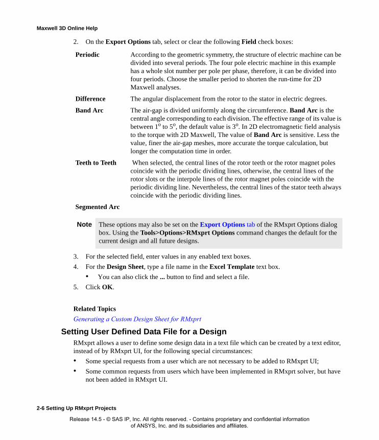
Maxwell 3D Online Help
2. On the Export Options tab, select or clear the following Field check boxes:
3. For the selected field, enter values in any enabled text boxes.
4. For the Design Sheet, type a file name in the Excel Template text box.
• You can also click the ... button to find and select a file.
5. Click OK.
Related Topics
Generating a Custom Design Sheet for RMxprt
Setting User Defined Data File for a DesignRMxprt allows a user to define some design data in a text file which can be created by a text editor, instead of by RMxprt UI, for the following special circumstances:
• Some special requests from a user which are not necessary to be added to RMxprt UI;
• Some common requests from users which have been implemented in RMxprt solver, but have not been added in RMxprt UI.
Periodic According to the geometric symmetry, the structure of electric machine can be divided into several periods. The four pole electric machine in this example has a whole slot number per pole per phase, therefore, it can be divided into four periods. Choose the smaller period to shorten the run-time for 2D Maxwell analyses.
Difference The angular displacement from the rotor to the stator in electric degrees.
Band Arc The air-gap is divided uniformly along the circumference. Band Arc is the central angle corresponding to each division. The effective range of its value is between 1o to 5o, the default value is 3o. In 2D electromagnetic field analysis to the torque with 2D Maxwell, The value of Band Arc is sensitive. Less the value, finer the air-gap meshes, more accurate the torque calculation, but longer the computation time in order.
Teeth to Teeth When selected, the central lines of the rotor teeth or the rotor magnet poles coincide with the periodic dividing lines, otherwise, the central lines of the rotor slots or the interpole lines of the rotor magnet poles coincide with the periodic dividing line. Nevertheless, the central lines of the stator teeth always coincide with the periodic dividing lines.
Segmented Arc
Note These options may also be set on the Export Options tab of the RMxprt Options dialog box. Using the Tools>Options>RMxprt Options command changes the default for the current design and all future designs.
2-6 Setting Up RMxprt Projects
Release 14.5 - © SAS IP, Inc. All rights reserved. - Contains proprietary and confidential information of ANSYS, Inc. and its subsidiaries and affiliates.

Maxwell 3D Online Help
When a user's requests have been implemented in an RMxprt solver but have not been added in RMxprt UI, the updated solver and the required file format for user defined data will be sent to the user. To use the feature of user defined data, the user must first edit the data file using a text editor according to the format provided. Then, select RMxprt>Design Settings to display the Design Set-tings dialog.
1. Select the User Defined Data tab.
2. Click the Enable checkbox to enable the use of User Defined Data.
3. User Defined Data may be entered directly into the text box. Click in the box and enter the data entries desired.
4. Alternatively, click Import File to import user defined data from an external file.
5. Browse to the directory containing the file.
6. Select the user defined data file which will be displayed in File name box.
7. Click Open to confirm the selection.
8. The file contents will be imported into the text box. Click OK to complete the setup.
User Defined Data is save in the design file. Changes to User Defined Data will cause existing solutions to become invalid.
Setting Up RMxprt Projects 2-7
Release 14.5 - © SAS IP, Inc. All rights reserved. - Contains proprietary and confidential information of ANSYS, Inc. and its subsidiaries and affiliates.
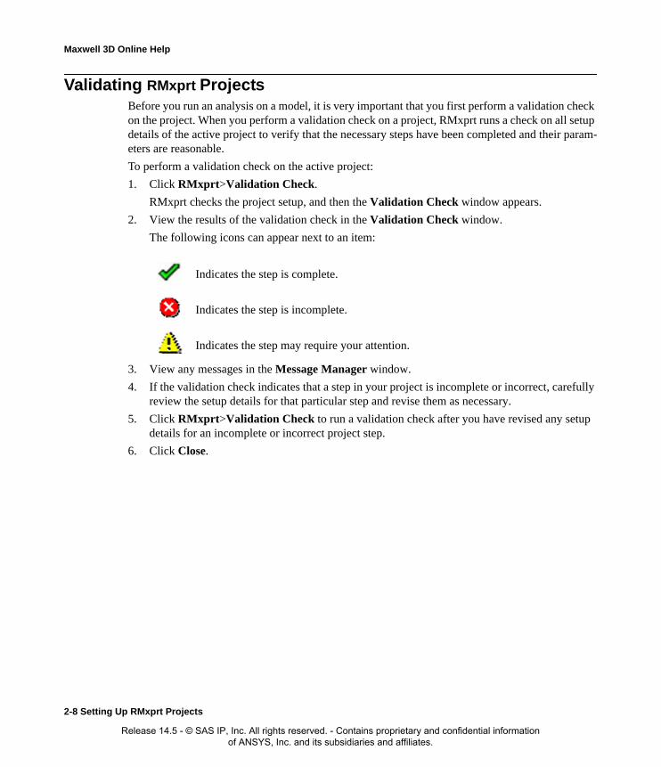
Maxwell 3D Online Help
Validating RMxprt ProjectsBefore you run an analysis on a model, it is very important that you first perform a validation check on the project. When you perform a validation check on a project, RMxprt runs a check on all setup details of the active project to verify that the necessary steps have been completed and their param-eters are reasonable.
To perform a validation check on the active project:
1. Click RMxprt>Validation Check.
RMxprt checks the project setup, and then the Validation Check window appears.
2. View the results of the validation check in the Validation Check window.
The following icons can appear next to an item:
3. View any messages in the Message Manager window.
4. If the validation check indicates that a step in your project is incomplete or incorrect, carefully review the setup details for that particular step and revise them as necessary.
5. Click RMxprt>Validation Check to run a validation check after you have revised any setup details for an incomplete or incorrect project step.
6. Click Close.
Indicates the step is complete.
Indicates the step is incomplete.
Indicates the step may require your attention.
2-8 Setting Up RMxprt Projects
Release 14.5 - © SAS IP, Inc. All rights reserved. - Contains proprietary and confidential information of ANSYS, Inc. and its subsidiaries and affiliates.
Maxwell 3D Online Help
Setting General Options in RMxprtDefault settings for many of the options in RMxprt may be set through the Tools>Options menu. To set general options for RMxprt:
1. Click Tools>Options>General Options.The General Options window appears, displaying six available tabs:
• Project Options
• Miscellaneous Options
• Default Units
• Analysis Options
• WebUpdate Options
2. Click each tab, and make the desired selections.
3. Click OK.
Related Topics:
Setting RMxprt Options
Setting Up RMxprt Projects 2-9
Release 14.5 - © SAS IP, Inc. All rights reserved. - Contains proprietary and confidential information of ANSYS, Inc. and its subsidiaries and affiliates.
Maxwell 3D Online Help
Setting RMxprt OptionsTo specify default settings for RMxprt options:
1. Click Tools>Options>RMxprt Options.The RMxprt Options window appears, displaying two available tabs:
• General Options
• Solver
2. Click each tab, and make the desired selections.
3. Click OK.
RMxprt Options: General Options TabThese options are set on the General Options tab of the RMxprt Options dialog box.
1. To change the default machine type when you initially insert a project, select one of the fol-lowing from the Default machine type pull-down list:
• Three Phase Induction Motor
• Single Phase Induction Motor
• Three Phase Synchronous Machine
• Brushless Permanent-Magnet DC Motor
• Adjust-Speed Synchronous Machine
• Permanent-Magnet DC Motor
• Switched Reluctance Motor
• Line-Start PM Synchronous Motor
• Universal Motor
• DC Machine
• Claw-Pole Synchronous Machine
• Three Phase Non-Salient Synchronous Machine
• Generic Rotating Machines
2. In the Threshold Options section, enter the Default conductivity and Default permeability values in siemens/m.
3. Select or clear the following check boxes:
Note Setting the material thresholds under Tools>Options impacts the default setting for the current and all future projects/designs. To change the material threshold for the current design only, use the RMxprt>Design Settings command and change the material thresholds on the Set Material Thresholds tab.
2-10 Setting Up RMxprt Projects
Release 14.5 - © SAS IP, Inc. All rights reserved. - Contains proprietary and confidential information of ANSYS, Inc. and its subsidiaries and affiliates.

Maxwell 3D Online Help
• Save before solving
• Apply variation deletions immediately
4. Click OK to close the dialog box.
Related Topics:
Setting the Material Threshold
RMxprt Options: Solver Tab
These options are set on the Solver tab of the RMxprt Options dialog box.
1. To set the solver options for RMxprt, select one of the following from the Default Process Priority pull-down list:
• Critical (highest) Priority (Not recommended)
• Above Normal Priority (Not recommended)
• Normal Priority
• Below Normal Priority
• Idle (lowest) Priority
2. Click OK to close the dialog box.
Note When you enable the Save before solving setting, the project is only saved if it has been modified since its last save.
Setting Up RMxprt Projects 2-11
Release 14.5 - © SAS IP, Inc. All rights reserved. - Contains proprietary and confidential information of ANSYS, Inc. and its subsidiaries and affiliates.

Maxwell 3D Online Help
Setting Machine OptionsIn RMxprt, you can set the following project options:
• Material threshold
• Model units
• Wire setting
Some of these and other options are available via the Tools>Options>Machine Options com-mand.
Specifying the Material ThresholdThe material threshold classifies the material type. For example, if the Conductivity threshold is set to be 106, then for any material with conductivity greater than or equal to 106 is treated as a conduc-tor. Otherwise, the material is treated as a non-conductor.
To set the material threshold for the model:
1. Click RMxprt>Design Settings.
The Set Material Threshold dialog box appears.
2. On the Material Threshold tab, type a value in the Conductivity Threshold box.
3. Type a value in the Permeability box.
4. Click OK.
Setting Model Units1. Click Machine>Units.
The Set Model Units dialog box appears.
2. Select the desired units from the pull-down list.
3. Select or clear the Rescale to new units check box.
4. Click OK.
Specifying the Machine Option for Wire SettingBefore you input data for your electric machine design project, please select the data file for wire gauge. RMxprt has numerous wire gauge specifications according to the various national Stan-dards for bare copper wire gauges (including both round and rectangular wires). Nevertheless, there exist no national standards for thickness for insulation, therefore different manufacturers produce electromagnetic wire with different thickness of insulation.The data file American.wir does not provide the data for thickness of insulation; the data file Chinese.wir does provide the data for thickness of insulation, but only for the purpose of reference to users. All wire files are stored in the file folder syslib.
To specify the wire setting:
1. Click Tools>Options>Machine Options.
The Machine Editor Options dialog box appears.
2. Select a one of the System Libraries such as American or Chinese from the Wire Setting
2-12 Setting Up RMxprt Projects
Release 14.5 - © SAS IP, Inc. All rights reserved. - Contains proprietary and confidential information of ANSYS, Inc. and its subsidiaries and affiliates.

Maxwell 3D Online Help
pull-down list.
3. Click OK.
The corresponding data for wire gauge appear automatically in the pop-up window for Machine>Wire.
Related Topic
Editing Wire Data
Editing Wire DataUsers must create their own data files for wire gauges according to the data for wire gauge and thickness of insulation provided by manufacturers. There are no national standards for thickness for insulation, therefore different manufacturers produce electromagnetic wire with different thickness of insulation.The data file American.wir does not provide the data for thickness of insulation; the data file Chinese.wir does provide the data for thickness of insulation, but only for the purpose of reference to users. These files are stored in the file folder syslib.
To define or edit wire data:
1. Click Machine>WireThe Edit Wire Data dialog box appears.
2. Select the units from the Unit System pull-down list.
English Unit System stands for British unit system, Metric Unit System stands for the metric unit system. When changing the unit system, the message box Note pops up to inform chang-ing in unit system is only for specifying input data unit, but not for transferring data between two unit systems
3. Click the Round or Rectangle tab for the wire shape you want to edit.
For Round:
Specify the desired values for Gauge No., Diameter, and/or Wrap.
For Rectangle:
a. Specify the desired values to limit ratios of the two sides.
b. Use the radio buttons specify whether to consider priority factors.
All Size for No Consideration of Priority Factors
Select the radio button All Size on the right to Type of Wire-Data Table and then click the command button Calculate in the window Wire Data, all the sectional areas of wire gauge with the ratio B/A between the wide and the narrow sides satisfying the condition
Gauge No. wire gauge index number.
Diameter diameter of bare copper wire, in mm or inch.
Wrap thickness of insulation wrap, in mm or inch.
Wire Shape Limit (B/A) max the maximum ratio between the wide and the narrow sides.
Wire Shape Limit (B/A) min the minimum ratio between the wide and the narrow sides.
Setting Up RMxprt Projects 2-13
Release 14.5 - © SAS IP, Inc. All rights reserved. - Contains proprietary and confidential information of ANSYS, Inc. and its subsidiaries and affiliates.

Maxwell 3D Online Help
(B/A) max > B / A > (B/A) min appear in the table Rectangular Wire Data.
Skip One for Consideration of Priority Factors
Select the radio button Skip One on the right to Type of Wire-Data Table and then click the command button Calculate in the window Wire Data, all the sectional areas of wire gauge with the ratio B/A between the wide and the narrow sides satisfying the condition (B/A) max > B / A > (B/A) min appear in three different modes in the table Rectangular Wire Data.
• At the cross of the odd columns and the odd rows, the sectional areas appear in black numbers (recommended to use).
• At the cross of the odd columns and the even rows or the even columns and the odd rows, the sectional areas appear in blue numbers (rarely used).
• At the cross of the even columns and the even rows, the sectional areas do not show (generally not used).
This is convenient for users to use recommended wire gauge according to R20 Priority Number Series.
4. Optionally, to add new rows or columns for the wire, click Add Row or Add Column.
5. Optionally, click Import to import wire data from a file.
6. Optionally, click Export to export the data you entered to a file.
7. When you are finished, click Save to save the data, and click Close to close the window.
Related Topic
Specifying the Machine Option for Wire Setting
2-14 Setting Up RMxprt Projects
Release 14.5 - © SAS IP, Inc. All rights reserved. - Contains proprietary and confidential information of ANSYS, Inc. and its subsidiaries and affiliates.
Maxwell 3D Online Help
Edit AC WindingsRMxprt can automatically arrange almost all commonly used single- or double-layer poly-phase ac windings provided all coils have the same number of turns. Users do not need to define coils one by one. For a double-layer winding, RMxprt can also handle the coils with half turns which are arranged in the order of even, odd, even, odd, …, as long as it is physically possible.
RMxprt also provides a very flexible tool, the Winding Editor, to allow users to design a variety of special winding types according to their own needs, such as compound single- and double-layer winding, big- and small-phase-spread variable-pole multiple-speed winding, sine-wave three-phase winding, and so forth. The Winding Editor is available to the following types of electric machines:
1.Three-phase induction motors
2.Single-phase induction motors
3.Three-phase synchronous motors and generators
4.Line-start permanent-magnet synchronous motors
5.Claw-pole alternators
6.Adjustable-speed permanent-magnet synchronous motors and generators
7.Brushless permanent-magnet DC motors
When you edit the AC winding of a new design for the first time, RMxprt creates a default winding arrangement based on the basic winding specifications: Number of Phases, Number of Poles, Number of Slots, Winding Layers, Conductors per Slot, and Coil Pitch. Then you can edit the winding configuration based on the default arrangement.
Enable Winding EditorSetting the Winding Type property to Editor enables the command Machine>Edit Layout on the menu bar. To display the dialog box Winding Editor:
1. Select Winding in the Project Tree. In the Properties window, set the Winding Type Value to Editor. To do this, click on the button Winding Type Value to display the WINDING Type
Setting Up RMxprt Projects 2-15
Release 14.5 - © SAS IP, Inc. All rights reserved. - Contains proprietary and confidential information of ANSYS, Inc. and its subsidiaries and affiliates.
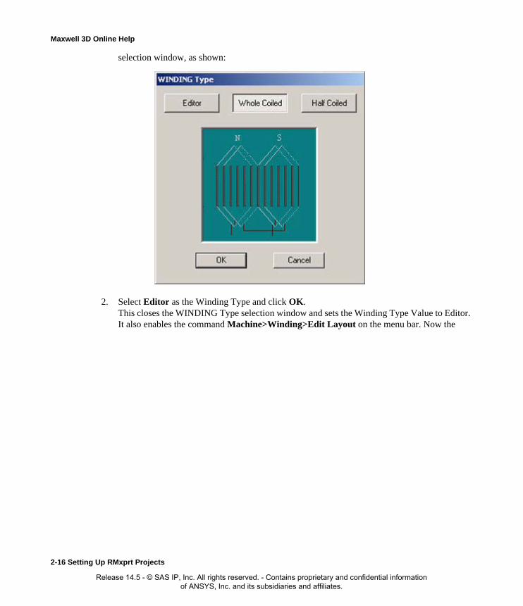
Maxwell 3D Online Help
selection window, as shown:
2. Select Editor as the Winding Type and click OK. This closes the WINDING Type selection window and sets the Winding Type Value to Editor. It also enables the command Machine>Winding>Edit Layout on the menu bar. Now the
2-16 Setting Up RMxprt Projects
Release 14.5 - © SAS IP, Inc. All rights reserved. - Contains proprietary and confidential information of ANSYS, Inc. and its subsidiaries and affiliates.
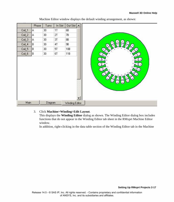
Maxwell 3D Online Help
Machine Editor window displays the default winding arrangement, as shown:
3. Click Machine>Winding>Edit Layout. This displays the Winding Editor dialog as shown. The Winding Editor dialog box includes functions that do not appear in the Winding Editor tab sheet in the RMxprt Machine Editor window.In addition, right-clicking in the data table section of the Winding Editor tab in the Machine
Setting Up RMxprt Projects 2-17
Release 14.5 - © SAS IP, Inc. All rights reserved. - Contains proprietary and confidential information of ANSYS, Inc. and its subsidiaries and affiliates.
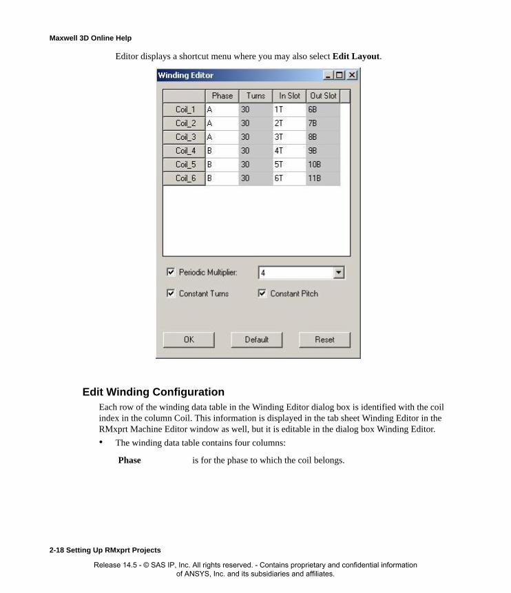
Maxwell 3D Online Help
Editor displays a shortcut menu where you may also select Edit Layout.
Edit Winding ConfigurationEach row of the winding data table in the Winding Editor dialog box is identified with the coil index in the column Coil. This information is displayed in the tab sheet Winding Editor in the RMxprt Machine Editor window as well, but it is editable in the dialog box Winding Editor.
• The winding data table contains four columns:
Phase is for the phase to which the coil belongs.
2-18 Setting Up RMxprt Projects
Release 14.5 - © SAS IP, Inc. All rights reserved. - Contains proprietary and confidential information of ANSYS, Inc. and its subsidiaries and affiliates.
Maxwell 3D Online Help
By changing the properties in the columns of the table, it is possible to arrange the distribution of coils of single and double layer winding of any type required.
• The Periodic Multiplier pull-down list box displays the numbers of unit machines for selec-tion. Selecting 1 means the whole slots are considered as one unit machine, and all the coils are listed in the table of the editing window. Selecting 2 lists half of the total coils in the table, and the whole slots are divided into two unit machines, etc.
• The Winding Editor also includes two check boxes:
• The Winding Editor dialog box includes three command buttons.
Turns is for the number of turns of the coil.
In Slots is for the slot number with the coil side current flowing in ('flow-in-side' for short). If 2 Layers are specified in the Winding Properties window, the slot number ends with a "T" to show the top layer.
Out Slots is for the slot number with the coil side current flowing out ("flow-out-side" for short). If 2 Layers are specified in the Winding Properties window, the slot number ends with a "B" to show the bottom layer.
Constant Turns Checking the check box (multiple choices) Constant Turns indicates that the number of turns keeps constant and the column Turns in the table is grayed (disabled). If the check box Constant Turns is unchecked, the column Turns in the table is brightened allowing for editing and modifying the number of turns.
Constant Pitch Checking this box grays the column Out Slots to the values cannot be edited. It means that the coil pitch is constant. For the two-layer windings, all the flow-in-side slots are defined as top layer, and all the flow-out-side slots as bottom layer. The flow-out-side slot number is automatically computed based on the input in the edit box Coil Pitch in the tab sheet Winding in the project tree in the RMxprt Machine Editor window, and the column Out Slot is disabled. When the check box Constant Pitch is unchecked, the column Out Slot is enabled to allow arbitrarily changing the slot pitch for each coil.
Default all the data in the table resumes to the situation of data from the automatic arrangement by RMxprt.
Reset all the data in the table resumes to the situation of data when the dialog box Winding Editor was first opened, or resumes to the data that you have saved.
OK to accept the current values and close the dialog box Winding Editor.
Setting Up RMxprt Projects 2-19
Release 14.5 - © SAS IP, Inc. All rights reserved. - Contains proprietary and confidential information of ANSYS, Inc. and its subsidiaries and affiliates.

Maxwell 3D Online Help
View Winding ConnectionsWhen you have specified the winding data, you can execute the following commands to display or hide the winding connections.
1. Click the menu command Machine>Winding>Connect All Coils.
Upon executing, the graphical display in the Machine Editor window shows the connections as shown:
2. To remove the connections in the graphical display in the Machine Editor window, select Machine>Winding>Disconnect All Coils.
3. Winding connections may also be viewed by shortcut menu. Right-click on the winding lay-out section of the Machine Editor window, a shortcut menu pops up. Select Connect All Coils or Disconnect All Coils to toggle the coils display on or off.
If you right-click on a slot layer, commands related to that slot layer will be enabled, and you will be able to view or hide only one coil or one phase connection related to the slot layer. You may copy the connection drawing to clipboard from the shortcut menu as well.
2-20 Setting Up RMxprt Projects
Release 14.5 - © SAS IP, Inc. All rights reserved. - Contains proprietary and confidential information of ANSYS, Inc. and its subsidiaries and affiliates.
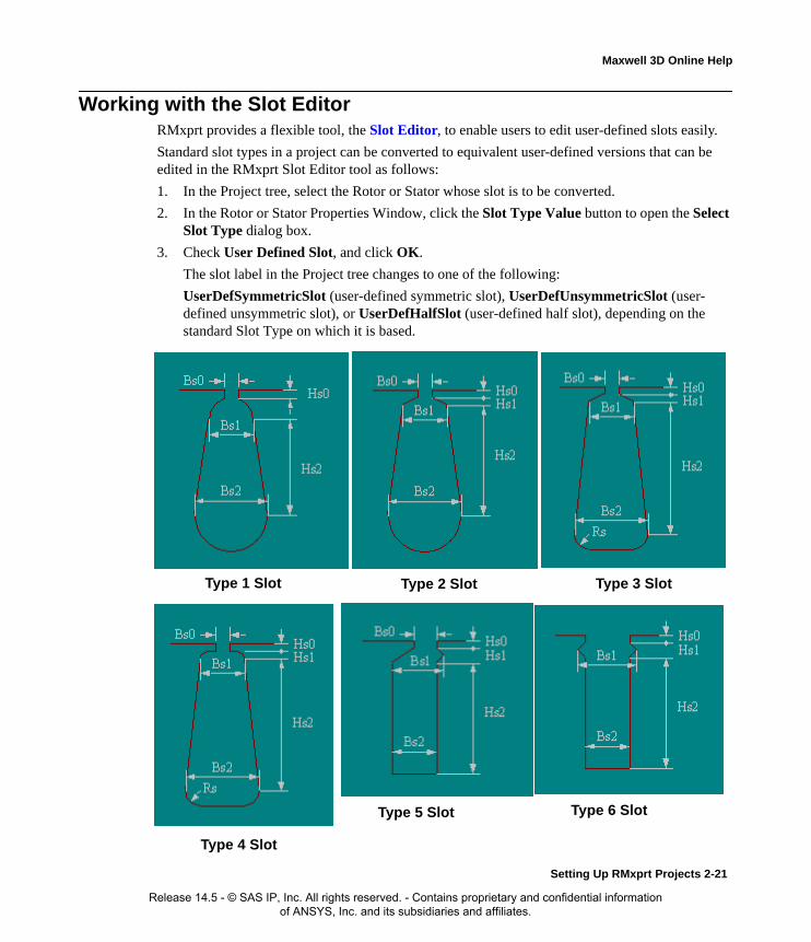
Maxwell 3D Online Help
Working with the Slot EditorRMxprt provides a flexible tool, the Slot Editor, to enable users to edit user-defined slots easily.
Standard slot types in a project can be converted to equivalent user-defined versions that can be edited in the RMxprt Slot Editor tool as follows:
1. In the Project tree, select the Rotor or Stator whose slot is to be converted.
2. In the Rotor or Stator Properties Window, click the Slot Type Value button to open the Select Slot Type dialog box.
3. Check User Defined Slot, and click OK.
The slot label in the Project tree changes to one of the following:
UserDefSymmetricSlot (user-defined symmetric slot), UserDefUnsymmetricSlot (user-defined unsymmetric slot), or UserDefHalfSlot (user-defined half slot), depending on the standard Slot Type on which it is based.
Type 1 Slot Type 2 Slot Type 3 Slot
Type 4 Slot
Type 6 SlotType 5 Slot
Setting Up RMxprt Projects 2-21
Release 14.5 - © SAS IP, Inc. All rights reserved. - Contains proprietary and confidential information of ANSYS, Inc. and its subsidiaries and affiliates.

Maxwell 3D Online Help
Standard Slot Types 1, 2, 3, 4, and 6 are symmetric. Standard slot Type 5 is unsymmetric. Half slots are present if the machine’s Rotor or Stator Properties Window includes a Half Slot prop-erty that has been enabled.
Related Topics
The Slot Editor Window
Slot Editor Data Editing View
Slot Editor Graphical View
The New Slot Dialog Box
Editing Slot Segments
Editing Unsymmetric Slots
Editing Half Slots
The Edit Slot Segments Dialog Box
2-22 Setting Up RMxprt Projects
Release 14.5 - © SAS IP, Inc. All rights reserved. - Contains proprietary and confidential information of ANSYS, Inc. and its subsidiaries and affiliates.

Maxwell 3D Online Help
The Slot Editor WindowWhen you select a user-editable slot in the Project tree, the Slot Editor window appears on the desk-top. The slot editor window is split into two frames. The left frame is the data editing view, which contains an expandable tree view of the slot and its constituent segments. The right frame shows a graphical view of the slot geometry formed by its segments.
Slot geometry types that can be edited are: symmetric, unsymmetric, and half-slot. A symmetric slot is shown in the figure below.
Related Topics
Slot Editor Data Editing View
Slot Editor Graphical View
The New Slot Dialog Box
Editing Slot Segments
Editing Unsymmetric Slots
Editing Half Slots
The Edit Slot Segments Dialog Box
Data Editing View
Graphical View
Setting Up RMxprt Projects 2-23
Release 14.5 - © SAS IP, Inc. All rights reserved. - Contains proprietary and confidential information of ANSYS, Inc. and its subsidiaries and affiliates.
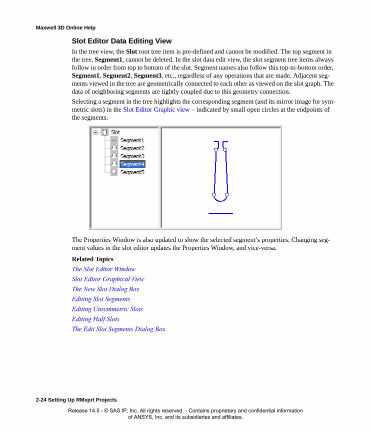
Maxwell 3D Online Help
Slot Editor Data Editing View
In the tree view, the Slot root tree item is pre-defined and cannot be modified. The top segment in the tree, Segment1, cannot be deleted. In the slot data edit view, the slot segment tree items always follow in order from top to bottom of the slot. Segment names also follow this top-to-bottom order, Segment1, Segment2, Segment3, etc., regardless of any operations that are made. Adjacent seg-ments viewed in the tree are geometrically connected to each other as viewed on the slot graph. The data of neighboring segments are tightly coupled due to this geometry connection.
Selecting a segment in the tree highlights the corresponding segment (and its mirror image for sym-metric slots) in the Slot Editor Graphic view – indicated by small open circles at the endpoints of the segments.
The Properties Window is also updated to show the selected segment’s properties. Changing seg-ment values in the slot editor updates the Properties Window, and vice-versa.
Related Topics
The Slot Editor Window
Slot Editor Graphical View
The New Slot Dialog Box
Editing Slot Segments
Editing Unsymmetric Slots
Editing Half Slots
The Edit Slot Segments Dialog Box
2-24 Setting Up RMxprt Projects
Release 14.5 - © SAS IP, Inc. All rights reserved. - Contains proprietary and confidential information of ANSYS, Inc. and its subsidiaries and affiliates.

Maxwell 3D Online Help
Editing Symmetric Slots
For a symmetric slot, right-clicking the Slot tree item pops up a context menu displaying the following choices:
• New Slot - opens the New Slot dialog box in which the user can select a new standard slot.
• Split to Half-Half - splits the slot into a Left Side and a Right Side transforming it into an unsymmetric slot. Each side then can be edited independently.
• Remove Left (or Right) Half, Remove Right Half - removes the segments for the left (or right) half of the symmetric slot, transforming the slot into a half-slot.
Related Topics
The New Slot Dialog Box
Editing Slot Segments
Editing Unsymmetric Slots
Editing Half Slots
Setting Up RMxprt Projects 2-25
Release 14.5 - © SAS IP, Inc. All rights reserved. - Contains proprietary and confidential information of ANSYS, Inc. and its subsidiaries and affiliates.
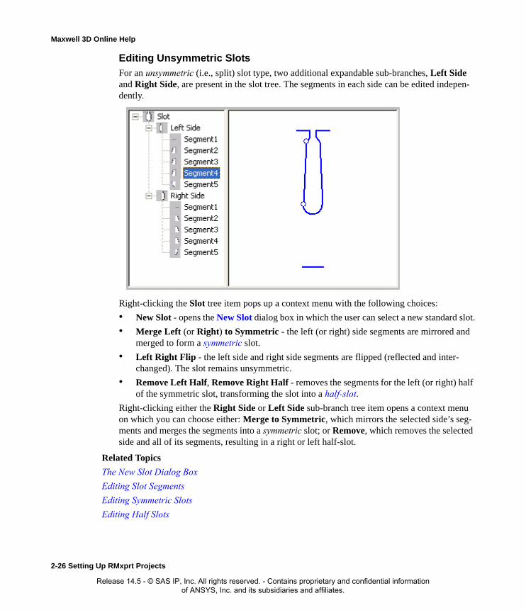
Maxwell 3D Online Help
Editing Unsymmetric Slots
For an unsymmetric (i.e., split) slot type, two additional expandable sub-branches, Left Side and Right Side, are present in the slot tree. The segments in each side can be edited indepen-dently.
Right-clicking the Slot tree item pops up a context menu with the following choices:
• New Slot - opens the New Slot dialog box in which the user can select a new standard slot.
• Merge Left (or Right) to Symmetric - the left (or right) side segments are mirrored and merged to form a symmetric slot.
• Left Right Flip - the left side and right side segments are flipped (reflected and inter-changed). The slot remains unsymmetric.
• Remove Left Half, Remove Right Half - removes the segments for the left (or right) half of the symmetric slot, transforming the slot into a half-slot.
Right-clicking either the Right Side or Left Side sub-branch tree item opens a context menu on which you can choose either: Merge to Symmetric, which mirrors the selected side’s seg-ments and merges the segments into a symmetric slot; or Remove, which removes the selected side and all of its segments, resulting in a right or left half-slot.
Related Topics
The New Slot Dialog Box
Editing Slot Segments
Editing Symmetric Slots
Editing Half Slots
2-26 Setting Up RMxprt Projects
Release 14.5 - © SAS IP, Inc. All rights reserved. - Contains proprietary and confidential information of ANSYS, Inc. and its subsidiaries and affiliates.

Maxwell 3D Online Help
Editing Half Slots
For a half slot, only the segments on one side of the slot can be edited.
Right-clicking the Slot tree item pops up a context menu displaying the following choices:
• New Slot - opens the New Slot dialog box in which the user can select a new standard slot.
• Merge to Symmetric - the left (or right) half-slot segments are mirrored and merged to form a symmetric slot.
• Left Right Flip - the left (or right) half-slot segments are flipped (reflected). The slot remains unsymmetric.
• Mirror - the left (or right) half-slot segments are mirrored (reflected and copied), trans-forming the slot into an unsymmetric slot.
Related Topics
The New Slot Dialog Box
Editing Slot Segments
Editing Symmetric Slots
Editing Unsymmetric Slots
The New Slot Dialog Box
Selecting New Slot in any of the Slot tree item context menus opens the New Slot dialog box.
Radio buttons allow the user to select a Symmetric Slot, Unsymmetrical Slot, Left Half Slot, or Right Half Slot as the type to be added. Clicking OK confirms the choice and replaces the existing slot type in the editor with a slot of the selected type. The new slot has only Segment1 present. The user must then edit the slot segments to form the desired slot geometry.
Setting Up RMxprt Projects 2-27
Release 14.5 - © SAS IP, Inc. All rights reserved. - Contains proprietary and confidential information of ANSYS, Inc. and its subsidiaries and affiliates.
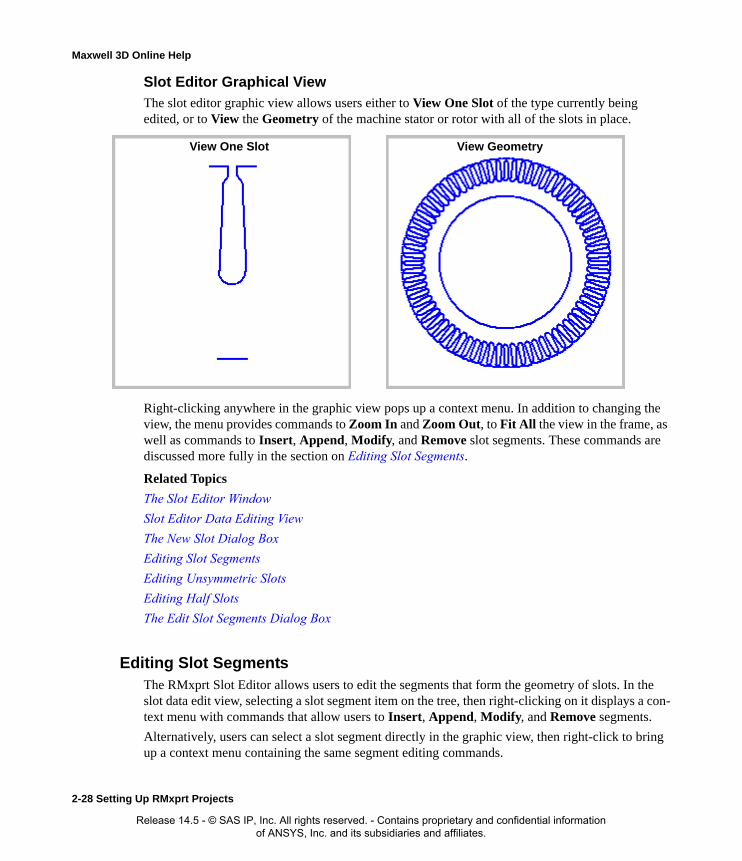
Maxwell 3D Online Help
Slot Editor Graphical View
The slot editor graphic view allows users either to View One Slot of the type currently being edited, or to View the Geometry of the machine stator or rotor with all of the slots in place.
Right-clicking anywhere in the graphic view pops up a context menu. In addition to changing the view, the menu provides commands to Zoom In and Zoom Out, to Fit All the view in the frame, as well as commands to Insert, Append, Modify, and Remove slot segments. These commands are discussed more fully in the section on Editing Slot Segments.
Related Topics
The Slot Editor Window
Slot Editor Data Editing View
The New Slot Dialog Box
Editing Slot Segments
Editing Unsymmetric Slots
Editing Half Slots
The Edit Slot Segments Dialog Box
Editing Slot SegmentsThe RMxprt Slot Editor allows users to edit the segments that form the geometry of slots. In the slot data edit view, selecting a slot segment item on the tree, then right-clicking on it displays a con-text menu with commands that allow users to Insert, Append, Modify, and Remove segments.
Alternatively, users can select a slot segment directly in the graphic view, then right-click to bring up a context menu containing the same segment editing commands.
View One Slot View Geometry
2-28 Setting Up RMxprt Projects
Release 14.5 - © SAS IP, Inc. All rights reserved. - Contains proprietary and confidential information of ANSYS, Inc. and its subsidiaries and affiliates.

Maxwell 3D Online Help
When a slot segment is selected, users can also modify the segment data directly in the desktop property window. Each edit triggers immediate validation. If edited values are improper, warning message windows are displayed describing the problem. Editing operations support Undo/Redo. Scripting functions are also available.
• Insert Segment -adds a segment before the currently selected segment. The added seg-ment is defined by the user in the Edit Slot Segment dialog box.
NOTE: You cannot insert a segment before Segment1.
• Append Segment - adds a segment after (i.e., below) the currently selected segment. The appended segment is defined by the user in the Edit Slot Segment dialog box.
• Modify Segment - modifies the currently selected segment. The segment is modified by the user in the Edit Slot Segment dialog box.
• Remove Segment - removes the currently selected segment. The ends of the segments on either side of the removed segment are joined when the segment is removed.
NOTE: Segment1 cannot be removed.
Setting Up RMxprt Projects 2-29
Release 14.5 - © SAS IP, Inc. All rights reserved. - Contains proprietary and confidential information of ANSYS, Inc. and its subsidiaries and affiliates.

Maxwell 3D Online Help
The Edit Slot Segment Dialog Box
In the Edit Slot Segment dialog, user can define the shape and dimension(s) of the segment to be added, inserted, or appended relative to the currently selected segment in the slot data edit view. As shown below, eight basic geometric shapes are provided for defining the slot segment. The Selected Shape panel shows dimensional parameters that affect the segment shape such as: height, starting and ending width, and radius. Parameters that determine the shape of the segment can be edited in the Segment Data panel.
1 2 3 4
8765
2-30 Setting Up RMxprt Projects
Release 14.5 - © SAS IP, Inc. All rights reserved. - Contains proprietary and confidential information of ANSYS, Inc. and its subsidiaries and affiliates.

Maxwell 3D Online Help
• Start width - sets the starting width and unit of measure. The value shown depends on the ending width of the previous segment and thus is not editable.
• End width - sets the ending width and unit of measure.
A drop-down box provides three additional options for controling the segment shape:
• Line edge (the default) - makes the segment a straight line.
• Arc offset on slot center - makes the segment an arc whose radius is determined by a user-specified offset from the rotor/stator center with respect to the slot center.
• Arc offset on tooth center - makes the segment an arc whose radius is determined by a user-specified offset from the rotor/stator center with respect to the tooth center.
Slot Center
Tooth Center
OffsetOffset
Setting Up RMxprt Projects 2-31
Release 14.5 - © SAS IP, Inc. All rights reserved. - Contains proprietary and confidential information of ANSYS, Inc. and its subsidiaries and affiliates.

Maxwell 3D Online Help
• Start width - sets the starting width and unit of measure. The value shown depends on the ending width of the previous segment and thus is not editable.
• Height -sets the height and unit of measure for the segment.
A drop-down box provides three options for controling the segment shape:
• End width (the default)- sets the ending width and unit of measure.
• Parallel slot - effectively sets the segment end width to the same value as the start width resulting in the slot sides being parallel to each other.
• Parallel tooth - sets the segment end width to a value such that the slot side is parallel to the adjacent slot side of the tooth formed between them.
• Start width - sets the starting width and unit of measure. The value shown depends on the ending width of the previous segment and thus is not editable.
• End width - sets the ending width and unit of measure.
• Start width - sets the starting width and unit of measure. The value shown depends on the ending width of the previous segment and thus is not editable.
• Radius - sets the radius and unit of measure for the segment.
2-32 Setting Up RMxprt Projects
Release 14.5 - © SAS IP, Inc. All rights reserved. - Contains proprietary and confidential information of ANSYS, Inc. and its subsidiaries and affiliates.

Maxwell 3D Online Help
Validation of the entered data is done when either the OK or Preview is clicked. If edited values are improper, warning message windows are displayed describing the problem. The Preview but-ton allows users to preview the current changes in the slot graph window without confirming the changes.
Clicking the OK button confirms the changes and closes the dialog box.
Clicking the Cancel button cancels the changes and closes the dialog box.
Related Topics
The New Slot Dialog Box
Editing Slot Segments
Editing Symmetric Slots
Editing Unsymmetric Slots
Editing Half Slots
Setting Up RMxprt Projects 2-33
Release 14.5 - © SAS IP, Inc. All rights reserved. - Contains proprietary and confidential information of ANSYS, Inc. and its subsidiaries and affiliates.

Maxwell 3D Online Help
2-34 Setting Up RMxprt Projects
Release 14.5 - © SAS IP, Inc. All rights reserved. - Contains proprietary and confidential information of ANSYS, Inc. and its subsidiaries and affiliates.

Maxwell 3D Online Help
Working with Variables in RMxprt A variable is a numerical value, mathematical expression, or mathematical function that can be assigned to a design parameter in RMxprt. Variables are useful in the following situations:
• When you expect to change a parameter often.
• When you expect to use the same parameter value often.
• When you intend to run a parametric analysis in which you specify a series of variable values within a range to solve.
• When you intend to optimize a parameter value by running an optimization analysis.
There are two types of variables in RMxprt:
Related Topics
Setting up an Optimetrics Analysis
Adding a Project Variable in RMxprtA project variable can be assigned to a parameter value in the RMxprt project in which it was cre-ated. RMxprt differentiates project variables from other types of variables by prefixing the variable name with the following symbol: $. You can manually include the symbol $ in the project vari-able's name when you create it, or RMxprt will automatically append the project variable's name with the symbol after you define the variable. Project variables can be used in any design within the project.
1. Click Project>Project Variables.
• Alternatively, right-click the project name in the project tree, and then click Project Vari-ables on the shortcut menu.
The Properties dialog box appears.
2. Under the Project Variables tab, click Add.
The Add Property dialog box appears.
3. In the Name box, type the name of the variable.
Project variable names must start with the symbol $ followed by a letter. Variable names may include alphanumeric characters and underscores ( _ ). The names of intrinsic functions and the pre-defined constant pi (π) cannot be used as variable names.
You can sort the project variables by clicking on the Name column header. By default, vari-
Project Variables A project variable can be assigned to any parameter value in the project in which it was created. RMxprt differentiates project variables from other types of variables by prefixing the variable name with the $ symbol. You can manually include the $ symbol in the project variable's name, or RMxprt can automatically append the $ after you define the variable.
Design Variables A design variable can be assigned to any parameter value in the RMxprt design in which it was created.
Setting up RMxprt Projects 2-35
Release 14.5 - © SAS IP, Inc. All rights reserved. - Contains proprietary and confidential information of ANSYS, Inc. and its subsidiaries and affiliates.
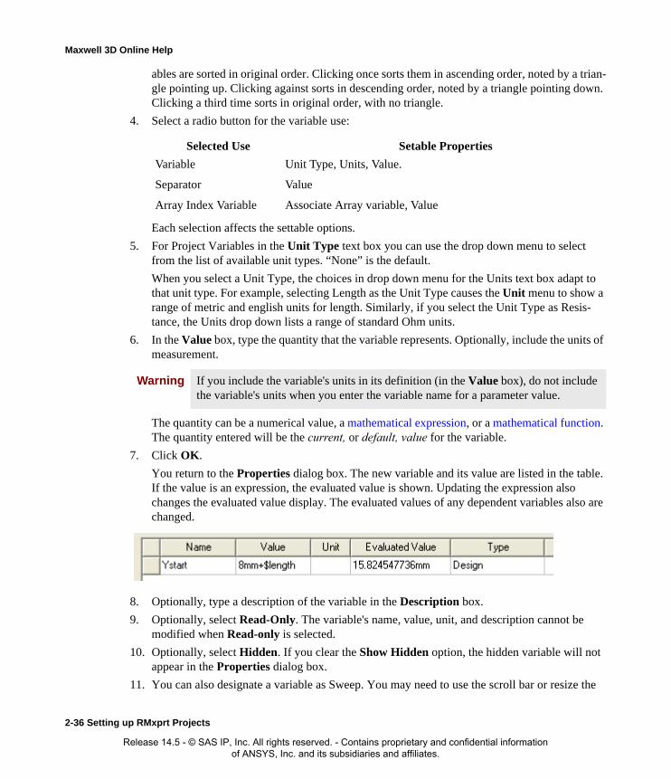
Maxwell 3D Online Help
ables are sorted in original order. Clicking once sorts them in ascending order, noted by a trian-gle pointing up. Clicking against sorts in descending order, noted by a triangle pointing down. Clicking a third time sorts in original order, with no triangle.
4. Select a radio button for the variable use:
Each selection affects the settable options.
5. For Project Variables in the Unit Type text box you can use the drop down menu to select from the list of available unit types. “None” is the default.
When you select a Unit Type, the choices in drop down menu for the Units text box adapt to that unit type. For example, selecting Length as the Unit Type causes the Unit menu to show a range of metric and english units for length. Similarly, if you select the Unit Type as Resis-tance, the Units drop down lists a range of standard Ohm units.
6. In the Value box, type the quantity that the variable represents. Optionally, include the units of measurement.
The quantity can be a numerical value, a mathematical expression, or a mathematical function. The quantity entered will be the current, or default, value for the variable.
7. Click OK.
You return to the Properties dialog box. The new variable and its value are listed in the table. If the value is an expression, the evaluated value is shown. Updating the expression also changes the evaluated value display. The evaluated values of any dependent variables also are changed.
8. Optionally, type a description of the variable in the Description box.
9. Optionally, select Read-Only. The variable's name, value, unit, and description cannot be modified when Read-only is selected.
10. Optionally, select Hidden. If you clear the Show Hidden option, the hidden variable will not appear in the Properties dialog box.
11. You can also designate a variable as Sweep. You may need to use the scroll bar or resize the
Selected Use Setable Properties
Variable Unit Type, Units, Value.
Separator Value
Array Index Variable Associate Array variable, Value
Warning If you include the variable's units in its definition (in the Value box), do not include the variable's units when you enter the variable name for a parameter value.
2-36 Setting up RMxprt Projects
Release 14.5 - © SAS IP, Inc. All rights reserved. - Contains proprietary and confidential information of ANSYS, Inc. and its subsidiaries and affiliates.

Maxwell 3D Online Help
dialog to view the check boxes.
The Sweep checkbox lets you designate variables to include in solution indexing as a way to permit faster post processing. Variables with Sweep unchecked are not used in solution index-ing. If a solution exists, checking or unchecking a variable’s Sweep setting produces a warning that the change will invalidate existing solutions. To continue, click OK to dismiss the warning dialog.
If a variable has dependent variables, the Sweep checkbox is disabled and cannot be changed.
12. Click OK.
The new variable can now be assigned to a parameter value in the project in which it was created.
Adding a Design Variable in RMxprtA design variable is associated with an RMxprt design. A design variable can be assigned to a parameter value in the RMxprt design in which it was created.
1. Click RMxprt>Design Properties.
• Alternatively, right-click the design name in the project tree, and then click Design Prop-erties on the shortcut menu.
The Properties dialog box appears opened on the Local Variables tab. From the Properties dialog you can Add, Add Array, Edit, or Remove variables.
Any existing Design variables are listed in the Properties dialog with the name followed by cells for Value, Unit, Evaluated Value, Type, Description, and Read-only and Hidden check boxes. A Show Hidden checkbox on the lower right of the Properties dialog controls the appearance of any Hidden variables .
Initially, leave the radio button with Value selected until you have defined a variable. The other radio buttons let you enable defined variables for Optimization, Tuning, Sensitivity or Statistics. Selecting one of these radio buttons adds a new column to the Variable definition
Setting up RMxprt Projects 2-37
Release 14.5 - © SAS IP, Inc. All rights reserved. - Contains proprietary and confidential information of ANSYS, Inc. and its subsidiaries and affiliates.

Maxwell 3D Online Help
row for which you can check or uncheck Include for regular variables for that kind of Optimet-rics simulation.
2. Click Add.
The Add Property dialog box appears.
3. In the Name box, type the name of the variable.
Variable names must start with a letter, and may include alphanumeric characters and under-scores ( _ ). The names of intrinsic functions and the pre-defined constant pi (π) cannot be used as variable names.
You can sort the variables by clicking on the Name column header. By default, variables are sorted in original order. Clicking once sorts them in ascending order, noted by a triangle point-ing up. Clicking against sorts in descending order, noted by a triangle pointing down. Clicking a third time sorts in original order, with no triangle.
4. Select a radio button for the variable use:
Each selection affects the settable options.
5. In the Unit Type text box you can use the drop down menu to select from the list of available unit types. “None” is the default.
When you select a Unit Type, the choices in drop down menu for the Units text box adapt to that unit type. For example, selecting Length as the Unit Type causes the Unit menu to show a range of metric and english units for length. Similarly, if you select the Unit Type as Resis-tance, the Units drop down lists a range of standard Ohm units.
6. In the Value box, type the quantity that the variable represents. Optionally, include the units of measurement.
The quantity can be a numerical value, a mathematical expression, or a mathematical function. The quantity entered will be the current (or default value) for the variable. If the mathematical expression includes a reference to an existing variable, this variable is treated as a dependent variable. The units for a dependent variable will automatically change to those of the indepen-dent variable on which the value depends. Additionally, dependent variables, though useful in many situations, cannot be the direct subject of optimization, sensitivity analysis, tuning, or
Selected Use Setable Properties
Variable Unit Type, Units, Value
Array Index Variable Associate Array variable, Value
Separator Value
Post Processing Variable Unit Type, Units, Value
Note If you include the variable's units in its definition (in the Value box), do not include the variable's units when you enter the variable name for a parameter value.
2-38 Setting up RMxprt Projects
Release 14.5 - © SAS IP, Inc. All rights reserved. - Contains proprietary and confidential information of ANSYS, Inc. and its subsidiaries and affiliates.
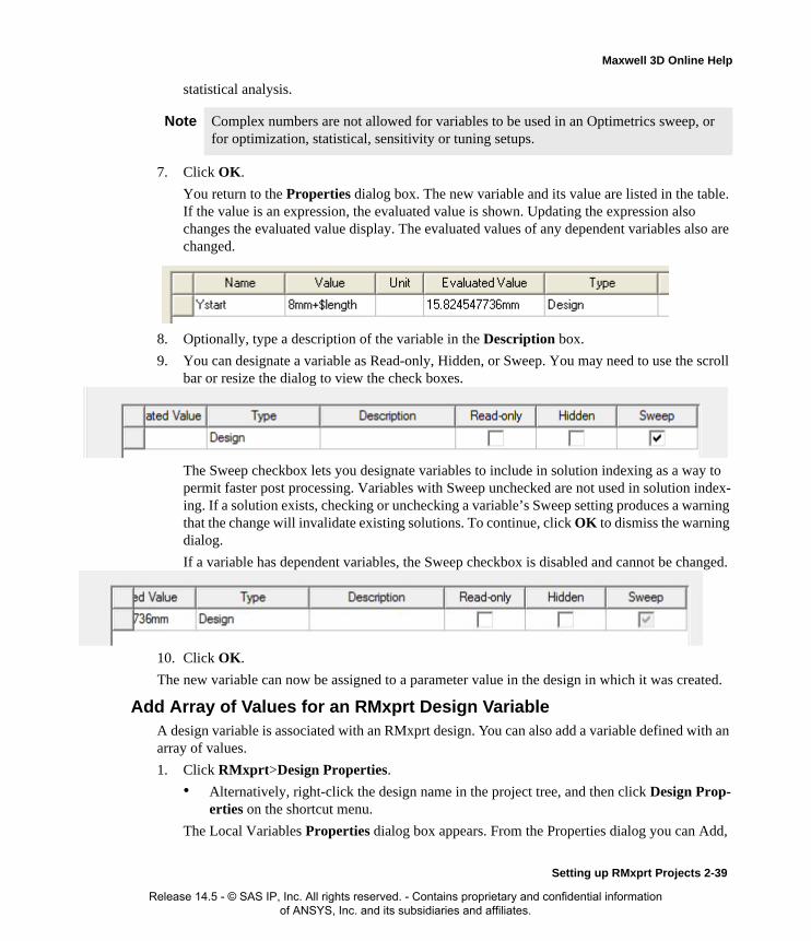
Maxwell 3D Online Help
statistical analysis.
7. Click OK.
You return to the Properties dialog box. The new variable and its value are listed in the table. If the value is an expression, the evaluated value is shown. Updating the expression also changes the evaluated value display. The evaluated values of any dependent variables also are changed.
8. Optionally, type a description of the variable in the Description box.
9. You can designate a variable as Read-only, Hidden, or Sweep. You may need to use the scroll bar or resize the dialog to view the check boxes.
The Sweep checkbox lets you designate variables to include in solution indexing as a way to permit faster post processing. Variables with Sweep unchecked are not used in solution index-ing. If a solution exists, checking or unchecking a variable’s Sweep setting produces a warning that the change will invalidate existing solutions. To continue, click OK to dismiss the warning dialog.
If a variable has dependent variables, the Sweep checkbox is disabled and cannot be changed.
10. Click OK.
The new variable can now be assigned to a parameter value in the design in which it was created.
Add Array of Values for an RMxprt Design VariableA design variable is associated with an RMxprt design. You can also add a variable defined with an array of values.
1. Click RMxprt>Design Properties.
• Alternatively, right-click the design name in the project tree, and then click Design Prop-erties on the shortcut menu.
The Local Variables Properties dialog box appears. From the Properties dialog you can Add,
Note Complex numbers are not allowed for variables to be used in an Optimetrics sweep, or for optimization, statistical, sensitivity or tuning setups.
Setting up RMxprt Projects 2-39
Release 14.5 - © SAS IP, Inc. All rights reserved. - Contains proprietary and confidential information of ANSYS, Inc. and its subsidiaries and affiliates.
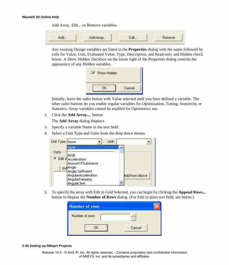
Maxwell 3D Online Help
Add Array, Edit... or Remove variables.
Any existing Design variables are listed in the Properties dialog with the name followed by cells for Value, Unit, Evaluated Value, Type, Description, and Read-only and Hidden check boxes. A Show Hidden checkbox on the lower right of the Properties dialog controls the appearance of any Hidden variables.
Initially, leave the radio button with Value selected until you have defined a variable. The other radio buttons let you enable regular variables for Optimization, Tuning, Sensitivity or Statistics. Array variables cannot be enabled for Optimetrics use.
2. Click the Add Array.... button.
The Add Array dialog displays.
3. Specify a variable Name in the text field.
4. Select a Unit Type and Units from the drop down menus.
5. To specify the array with Edit in Grid Selected, you can begin by clicking the Append Rows... button to display the Number of Rows dialog. (For Edit in plain text field, see below.)
2-40 Setting up RMxprt Projects
Release 14.5 - © SAS IP, Inc. All rights reserved. - Contains proprietary and confidential information of ANSYS, Inc. and its subsidiaries and affiliates.
Maxwell 3D Online Help
6. Specify a value and click OK.
This displays a list of indexed data rows in the Add Array dialog. You can type any data value in the cells. If you enter alphanumeric text in a cell it must be delimited by double quotes. You can edit the rows relative a row selection by clicking buttons to Add Row Above, Add Row Below, or Remove Row. All cells must contain a value.
7. When you have completed the array, click OK to close the dialog,
The Array variable is listed in the Design Properties dialog as a Local Variable. The array variable value field includes the array contents in brackets with the unindexed data values delimited by commas.
If you elected to edit the array Edit in plain text field in the Add Array dialog, the bracketed and comma delimited format is used.
Defining Mathematical Functions in RMxprtA mathematical function is an expression that references another defined variable. A function's def-inition can include both expressions and variables.
The following mathematical functions may be used to define expressions:
The predefined variables X, Y, Z, Phi, Theta, R, and Rho must be entered as such. X, Y, and Z are the rectangular coordinates. Phi, Theta, and Rho are the spherical coordinates. R is the cylindrical radius, and Rho is the spherical radius.
If you do not specify units, all trigonometric expressions expect their arguments to be in radians, and the inverse trigonometric functions’ return values are in radians. If you want to use degrees, you must supply the unit name deg. When the argument to a trigonometric expression is a variable, the units are assumed to be radians. These function names are reserved and may not be used as vari-able names.
Defining an Expression in RMxprtExpressions are mathematical descriptions that typically contain intrinsic functions, such as sin(x), and arithmetic operators, such as +, -, *, and /, as well as defined variables. For example, you could define: x_size = 1mm, y_size = x_size + sin(x_size).
The symbol, pi ( ), is the only available pre-defined constant. It may not be reassigned a new value.
Basic functions
/, +, -, *, mod (modulus), ** (exponentiation), - (Unary minus), == (equals), ! (not), != (not equals), > (greater than), < (less than), >= (greater than equals), <= (less than equals), && (logical and), || (logical or)
Intrinsic functions
if, sqn, abs, exp, pow, ln (natural log), sqrt
Trigonometricexpressions
sin, cos, tan, asin, acos, atan, sinh, cosh, tanh
π
Setting up RMxprt Projects 2-41
Release 14.5 - © SAS IP, Inc. All rights reserved. - Contains proprietary and confidential information of ANSYS, Inc. and its subsidiaries and affiliates.

Maxwell 3D Online Help
Numerical values may be entered in Ansoft's shorthand for scientific notation. For example, 5x10⁷ could be entered as 5e7.
Using Valid Operators for Expressions in RMxprtThe operators that can be used to define an expression or function have a sequence in which they are performed. The following list shows both the valid operators and the sequence in which they are accepted (listed in decreasing precedence):
Using Intrinsic Functions in Expressions in RMxprtRMxprt recognizes a set of intrinsic trigonometric and mathematical functions that can be used to define expressions. Intrinsic function names are reserved and may not be used as variable names.
( ) parenthesis 1
! not 2
^ (or **) exponentiation
(If you use "**" for exponentiation, as in previous software versions, it is automatically changed to "^".)
3
- unary minus 4
* multiplication 5
/ division 5
+ addition 6
- subtraction 6
== equals 7
!= not equals 7
> greater than 7
< less than 7
>= greater than or equal to 7
<= less than or equal to 7
&& logic and 8
|| logic or 8
2-42 Setting up RMxprt Projects
Release 14.5 - © SAS IP, Inc. All rights reserved. - Contains proprietary and confidential information of ANSYS, Inc. and its subsidiaries and affiliates.

Maxwell 3D Online Help
The following intrinsic functions may be used to define expressions:
Function Description Syntax
abs Absolute value (|x|) abs(x)
sin Sine sin(x)
cos Cosine cos(x)
tan Tangent tan(x)
asin Arcsine asin(x)
acos Arccosine acos(x)
atan Arctangent (in range of -π/4 to π/4 degrees)
atan(x)
atan2 Arctangent (in range of -π/2 to π/2 degrees)
atan2(y,x)
asinh Hyperbolic Arcsine asinh(x)
atanh Hyperbolic Arctangent atanh(x)
sinh Hyperbolic Sine sinh(x)
cosh Hyperbolic Cosine cosh(x)
tanh Hyperbolic Tangent tanh(x)
even Returns 1 if integer part of the number is even; returns 0 otherwise.
even(x)
odd Returns 1 if integer part of the number is odd; returns 0 otherwise.
odd(x)
sgn Sign extraction sgn(x)
exp Exponential (ex) exp(x)
pow Raise to power (xy) pow(x,y)
if If if(cond_exp,true_exp, false_exp)
pwl Piecewise Linear with linear extrapolation on x
pwl(dataset_exp, variable)
Setting up RMxprt Projects 2-43
Release 14.5 - © SAS IP, Inc. All rights reserved. - Contains proprietary and confidential information of ANSYS, Inc. and its subsidiaries and affiliates.

Maxwell 3D Online Help
Using Piecewise Linear Functions in Expressions in RMxprtThe following piecewise linear intrinsic functions are accepted in expressions:
pwl (dataset_expression, variable)
pwlx (dataset_expression, variable)
pwl_periodic (dataset_expression, variable)
pwlx Piecewise Linear x with linear extrapolation on x
pwlx(dataset_exp, variable)
pwl_periodic Piecewise Linear with periodic extrapolation on x
pwl_periodic(dataset_exp, variable)
sqrt Square Root sqrt(x)
ln Natural Logarithm
(The "log" function has been discontinued. If you use "log(x)" in an expression, the software automatically changes it to "ln(x)".)
ln(x)
log10 Logarithm base 10 log10(x)
int Truncated integer function
int(x)
nint Nearest integer nint(x)
max Maximum value of two parameters
max(x,y)
min Minimum value of two parameters
min(x,y)
mod Modulus mod(x,y)
rem Fractional part (remainder)
rem(x.y)
Note If you do not specify units, all trigonometric functions interpret their arguments as radians. Likewise, inverse trigonometric functions' return values are in given in radians. When the argument to a trigonometric expression is a variable, the units are assumed to be radians. If you want values interpreted in degrees, supply the argument with the unit name deg.
2-44 Setting up RMxprt Projects
Release 14.5 - © SAS IP, Inc. All rights reserved. - Contains proprietary and confidential information of ANSYS, Inc. and its subsidiaries and affiliates.
Maxwell 3D Online Help
The pwl and pwlx functions interpolate along the x-axis and returns a corresponding y value. The pwl_periodic function also interpolates along the x-axis but periodically.
Using Dataset Expressions in RMxprtDataset expressions take the following form:
dset((x0,y0), ..., (xn,yn))
These expressions may be used as the first parameter to piecewise linear (pwl, pwlx and pwl_periodic) functions, and may also be assigned to variables, in which case the variable may be used as the second parameter to pwl, pwlx and pwl_periodic functions.
Dataset expressions are derived from a series of points in a plot created in the Datasets dialog box. Each plot consists of straight line segments whose vertices represent their end points. A curve is fit-ted to the segments of the plot, and an expression is derived from the curve that best fits the seg-mented plot. The created expression is then used in the piecewise linear intrinsic functions.
Assigning Variables in RMxprtTo assign a variable to a parameter in RMxprt:
• Type the variable name or mathematical expression in place of a parameter value in a Value box.
If you typed a variable name that has not been defined, the Add Variable dialog box appears, enabling you to define the design variable.
If you typed a variable name that included the $ prefix, but that has not been defined, the Add Variable dialog box appears, enabling you to define the project variable.
You can assign a variable to nearly any design parameter assigned a numeric value in RMxprt.
Choosing a Variable to Optimize in RMxprtBefore a variable can be optimized, you must specify that you intend for it to be used during an optimization analysis in the Properties dialog box.
1. If the variable is a design variable, click RMxprt>Design Properties.
If the variable is a project variable, click Project>Project Variables.
The Properties dialog box appears.
2. Click the tab that lists the variable you want to optimize.
3. Click the row containing the variable you want to optimize.
4. Select the Optimization option.
5. For the variable you want to optimize, select Include.
The selected variable is now available for optimization in an optimetrics setup defined in the current design or project.
6. Optionally, override the default minimum and maximum values that Optimetrics will use for the variable in every optimization analysis. During optimization, the optimizer does not con-
Note Dependent variables cannot be optimized.
Setting up RMxprt Projects 2-45
Release 14.5 - © SAS IP, Inc. All rights reserved. - Contains proprietary and confidential information of ANSYS, Inc. and its subsidiaries and affiliates.

Maxwell 3D Online Help
sider variable values that lie outside of this range.
7. Click OK.
Related Topics
Setting up an Optimization Analysis
Including a Variable in a Sensitivity Analysis in RMxprtBefore a variable can be included in a sensitivity analysis, you must specify that you intend for it to be used during a sensitivity analysis in the Properties dialog box.
1. If the variable is a design variable, click RMxprt>Design Properties.
If the variable is a project variable, click Project>Project Variables.
The Properties dialog box appears.
2. Click the tab that lists the variable you want to include in the sensitivity analysis.
3. Click the row containing the variable you want to include in the sensitivity analysis.
4. Select the Sensitivity option.
5. For the variable you want to include in the sensitivity analysis, select Include.
The selected variable is now available for sensitivity analysis in a sensitivity setup defined in the current design or project.
6. Optionally, override the default minimum and maximum values that Optimetrics will use for the variable in every sensitivity analysis. During sensitivity analysis, Optimetrics will not con-sider variable values that lie outside of this range.
7. Optionally, override the default initial displacement value that Optimetrics will use for the variable in every sensitivity analysis. During sensitivity analysis, Optimetrics will not consider a variable value for the first design variation that is greater than this step size away from the starting variable value.
8. Click OK.
Related Topics
Setting up a Sensitivity Analysis
Choosing a Variable to Tune in RMxprtBefore a variable can be tuned, you must specify that you intend for it to be tuned in the Properties dialog box.
1. If the variable is a design variable, click RMxprt>Design Properties.
If the variable is a project variable, click Project>Project Variables.
The Properties dialog box appears.
2. Click the tab that lists the variable you want to tune.
Note Dependent variables cannot be included in a sensitivity analysis.
2-46 Setting up RMxprt Projects
Release 14.5 - © SAS IP, Inc. All rights reserved. - Contains proprietary and confidential information of ANSYS, Inc. and its subsidiaries and affiliates.

Maxwell 3D Online Help
3. Click the row containing the variable you want to tune.
4. Select the Tuning option.
5. For the variable you want to tune, select Include.
6. Click OK.
The selected variable is now available for tuning in the Tune dialog box.
Related Topics
Tuning a Variable
Including a Variable in a Statistical Analysis in RMxprtBefore a variable can be included in a statistical analysis, you must specify that you intend for it to be used during a statistical analysis in the Properties dialog box.
1. If the variable is a design variable, click RMxprt>Design Properties.
If the variable is a project variable, click Project>Project Variables.
The Properties dialog box appears.
2. Click the tab that lists the variable you want to include in the statistical analysis.
3. Click the row containing the variable you want to include in the statistical analysis.
4. Select the Statistics option.
5. For the variable you want to include in the statistical analysis, select Include.
The selected variable is now available for statistical analysis in a statistical setup defined in the current design or project.
6. Optionally, override the distribution criteria that Optimetrics will use for the variable in every statistical analysis.
7. Click OK.
Related Topics
Setting up a Statistical Analysis
Note Dependent variables cannot be tuned.
Note Dependent variables cannot be included in a statistical analysis.
Setting up RMxprt Projects 2-47
Release 14.5 - © SAS IP, Inc. All rights reserved. - Contains proprietary and confidential information of ANSYS, Inc. and its subsidiaries and affiliates.

Maxwell 3D Online Help
2-48 Setting up RMxprt Projects
Release 14.5 - © SAS IP, Inc. All rights reserved. - Contains proprietary and confidential information of ANSYS, Inc. and its subsidiaries and affiliates.

3
Wire Specification Libraries
RMxprt contains a library of standard wire sizes for use in machine designs. These wire gauge specifications are based on widely used standards currently available in industry.
Wire Specification Libraries 3-1
Release 14.5 - © SAS IP, Inc. All rights reserved. - Contains proprietary and confidential information of ANSYS, Inc. and its subsidiaries and affiliates.

Maxwell 3D Online Help
Configure Wire Specification LibraryIn order to be able to select wire size for your design specifications, your need to configure wire specification library before you insert a new design in your project. RMxprt provides following wire gauge specifications based on the current widely used standards for bare copper wire gauges (including both round and rectangular wires):
These files are stored in the file folder <Library Directory>/syslib, where <Library Directory> is set via Tools>Options>General Options>Project Options.
American.wirFile American.wir provides dimensions for all ANSI
bare wires.
ANSI_SingleFilm.wir
ANSI_HeavyFilm.wir
ANSI_TripleFilm.wir
ANSI_QuadFilm.wir
Files ANSI*.wir provide dimensions for bare and film insulated copper wires with single, heavy, triple and quad builds of integer and half AWG numbers.
AWG_Int_SingleFilm.wir
AWG_Int_HeavyFilm.wir
AWG_Int_TripleFilm.wir
AWG_Int_QuadFilm.wir
Files AWG_Int*.wir provide dimensions of integer AWG numbers.
Chinese.wir
IEC_R20Grade1.wir
IEC_R20Grade2.wir
IEC_R20Grade3.wir
IEC_R40Grade1.wir
IEC_R40Grade2.wir
IEC_R40Grade3.wir
Files IEC_R20*.wir provide dimensions of enameled copper wires with Grade-1, 2, and 3 insulations of
R20 series. Files IEC_R40*.wir provide dimensions of R40 series. In files IEC*.wir, the gauge numbers
are equivalent to the AWG numbers according to the nominal diameters.
3-2 Wire Specification Libraries
Release 14.5 - © SAS IP, Inc. All rights reserved. - Contains proprietary and confidential information of ANSYS, Inc. and its subsidiaries and affiliates.

Maxwell 3D Online Help
Specify the Wire SettingTo specify the wire setting:
1. Click Tools>Options>Machine Options. The Machine Editor Options dialog box appears, as shown.
2. Select one of the following library locations:
• System Libraries - libraries installed with Maxwell, located at <Library Directory>/syslib
• User Libraries - user created public libraries, located at <Library Directory>/userlib
• Personal Libraries - user created private libraries, located at <Project Directory>/Person-alLib
where <Library Directory> and <Project Directory> are set via Tools>Options>Gen-eral Options>Project Options.
3. Select one specification library from the pull-down list in Wire Setting area.
4. Click OK to close the dialog box.
Note The new wire setting does not affect all existing designs, but affects all designs inserted later. The selected wire specification library is saved with each design.
Wire Specification Libraries 3-3
Release 14.5 - © SAS IP, Inc. All rights reserved. - Contains proprietary and confidential information of ANSYS, Inc. and its subsidiaries and affiliates.

Maxwell 3D Online Help
Hint To modify the wire specification library saved in an existing design, double click the design to active its Machine Editor window, click Machine>Wire, modify wire data or Import a wire specification library file, and Save wire data to the design.
3-4 Wire Specification Libraries
Release 14.5 - © SAS IP, Inc. All rights reserved. - Contains proprietary and confidential information of ANSYS, Inc. and its subsidiaries and affiliates.

Maxwell 3D Online Help
Edit Wire DataUsers can modify wire data for the active design and export to create their own data files for the wire gauges according to the data for the wire gauge and thickness of insulation provided by the manufacturers.
To define or edit wire data:
1. Click Machine>Wire. The dialog box Edit Wire Data appears, as shown.
2. Select the units from the pull-down list Unit System:.
• in: English Unit System stands for British unit system.
• mm: Metric Unit System stands for the metric unit system.
There are two tabs, Round and Rectangle, in the dialog box for editing wire shapes.
Note Changing the unit system is only for specifying input data unit, not for transferring data between two unit systems.
Wire Specification Libraries 3-5
Release 14.5 - © SAS IP, Inc. All rights reserved. - Contains proprietary and confidential information of ANSYS, Inc. and its subsidiaries and affiliates.

Maxwell 3D Online Help
Edit Round Wire DataClick the tab Round for editing the round wire shape. In the Round tab sheet, you specify the desired values for Gauge No., Diameter, and/or Wrap.
• Gauge No.: wire gauge index number.
• Diameter: diameter of bare copper wire, in mm or inch.
• Wrap: thickness of insulation wrap, in mm or inch as shown.
You can edit the wire data in the spreadsheet by doing the following:
1. Directly modify the wire data.
2. Add new rows for the wire by clicking Add Row.
3. Delete rows for the wire by clicking Delete Row.
3-6 Wire Specification Libraries
Release 14.5 - © SAS IP, Inc. All rights reserved. - Contains proprietary and confidential information of ANSYS, Inc. and its subsidiaries and affiliates.

Maxwell 3D Online Help
Edit Rectangular Wire DataClick the tab Rectangle for editing the rectangular wire shape. In the Rectangle tab sheet, as shown below, specify the desired values for Wire Shape Limit, Table Type, and Sides.
Wire Shape LimitSpecify the desired values to limit ratios of the two sides.
• Wire Shape Limit (B/A) max: the maximum ratio between the wide and the narrow sides.
• Wire Shape Limit (B/A) min: the minimum ratio between the wide and the narrow sides.
Recommended Wire Sides
Use the radio buttons to specify whether to consider priority factors.
• All Size:
For No Consideration of Priority Factors. Click the command button Calculate in the dia-log box Edit Wire Data, all the sectional areas of wire gauge with the ratio B/A between the wide and the narrow sides satisfying the condition (B/A)max > B / A > (B/A) min appear in the spread sheet table.
• Skip One:
Wire Specification Libraries 3-7
Release 14.5 - © SAS IP, Inc. All rights reserved. - Contains proprietary and confidential information of ANSYS, Inc. and its subsidiaries and affiliates.

Maxwell 3D Online Help
For Consideration of Priority Factors. Click the command button Calculate in the dialog box Edit Wire Data, all the sectional areas of wire gauge with the ratio B/A between the wide and the narrow sides satisfying the condition (B/A) max > B / A > (B/A) min appear in three different modes in the spread sheet.
1. At the cross of the odd columns and the odd rows, the sectional areas appear in black numbers (recommended to use).
2. At the cross of the odd columns and the even rows or the even columns and the odd rows, the sectional areas appear in blue numbers (rarely used).
3. At the cross of the even columns and the even rows, the sectional areas do not show (generally not used).
This is convenient for users to use recommended wire gauge according to R20 Priority Number Series.
Wire Sides
You can edit the wire data in the spread sheet:
1. Directly modify the wire data.
2. Add new rows or columns for the wire, click Add Row or Add Column.
3. Delete rows or columns for the wire, click Delete Row or Delete Column.
Export/Import Wire DataAfter editing, you can export the wire data to a file:
1. Click Export, the Export File dialog box appears. The default directory for an exported wire data file is userlib.
2. Provide the file name to export in the File name: edit box and use the default file type Wire Size File (*.wir).
3. Click OK to return to the Edit Wire Data dialog box.
Before editing, you can import the wire data from a file:
1. Click Import, the Import File dialog box appears.
2. Provide the file name to import in the File name: edit box (or by browsing) and use the default file type Wire Size File (*.wir).
3. Click OK to return to the Edit Wire Data dialog box.
Save Wire Data1. During editing, you can save the wire data you entered by clicking Save.
2. When you finish editing, click Close to close the Edit Wire Data dialog box.
Note Save wire data only updates the wire data in the active design.
3-8 Wire Specification Libraries
Release 14.5 - © SAS IP, Inc. All rights reserved. - Contains proprietary and confidential information of ANSYS, Inc. and its subsidiaries and affiliates.

4
Working with Materials in RMxprt
RMxprt shares many common functions related to materials and material handling with Maxwell3D and Maxwell2D. For general topics such as, Assigning Materials, Searching for Mate-rials, Adding New Materials, and Viewing and Modifying Material Attributes, see the topics in Maxwell help under Assigning Materials.
RMxprt includes a material library containing common materials used in motor design. However, this library needs to be configured so that it is automatically loaded for any new RMxprt design. Once the library is configured, you can add, remove, and edit RMxprt materials in two main ways:
• Using the Tools>Edit Configured Libraries>Materials menu command.
• Right-clicking Materials in the project tree and selecting Edit All Libraries.
Editing definitions from the project window does not modify the configured libraries for any partic-ular design. To consider the current design, use the Tools>Edit Configured Libraries option. Doing so ensures that new libraries are added to the configured list for the current design. If you edit materials from this command for the current and then export them, they will also be available to assign to objects in other designs.
Related Topics:
Configuring Design Libraries
Material Library Management for RMxprt
Working with Materials in RMxprt 4-1
Release 14.5 - © SAS IP, Inc. All rights reserved. - Contains proprietary and confidential information of ANSYS, Inc. and its subsidiaries and affiliates.

Maxwell 3D Online Help
Material Library Management for RMxprtThe three most crucial electromagnetic materials in the electric machine are soft-magnetic material (silicon steel sheet), hard-magnetic material (permanent magnet) and electromagnetic wire. It is convenient to create a data file library for them for quick selection while inputting design data.
4-2 Working with Materials in RMxprt
Release 14.5 - © SAS IP, Inc. All rights reserved. - Contains proprietary and confidential information of ANSYS, Inc. and its subsidiaries and affiliates.

Maxwell 3D Online Help
Soft-Magnetic MaterialsThe stator and the rotor iron cores in the electric machine are generally laminated with punched sheets of nonlinear soft-magnetic silicon steel. Some special types of electric machines, such as moment motor, turbo-generator etc., use integrated solid rotor iron core of soft-magnetic material. For magnetic field analysis and core loss analysis of the electric machine, the magnetization char-acteristics (B-H Curve) and the loss characteristics (B-P Curve) of the iron-core material must be defined. The dialogue boxes to do so are accessed from the View/Edit Material window, which, in turn is accessed from the Edit Libraries window. Access to the window for editing the B-H curve is enabled when you set the Magnetic Permeability value to nonlinear (rather than simple or Aniso-tropic). When you set the value to nonlinear, the value field changes to a B-H Curve button. Click the B-H curve button to open the window.
For the loss characteristics (B-P Curve), you first set the Core Loss Type of the material to Elec-trical Steel (rather than None or Power Ferrite) as a material property in the View/Edit Material window. When you do so, this enables the Calculate Properties selection for drop down at the bot-tom of the window. Select Core Loss Coefficient from the drop down menu to open the B-P Curve window.
Related Topics:
Adding New Materials to an RMxprt Project
Setting the Material Threshold for RMxprt
Assigning Materials
Removing Materials
Validating Materials
Sorting Materials
Viewing and Modifying Material Attributes
Copying Materials
Exporting Materials to a Library
Calculating Properties for Core Loss in RMxprt (BP Curve)
Adding New Materials to an RMxprt ProjectYou can add a new material to a project or to the global user-defined material library. To make the new project material available to all projects, you must export the material to a global user-defined material library.
To assign a material to an object:
1. Click Tools>Edit Configured Libraries>Materials.
• In the project tree, you can also right-click Materials, and select Edit All Libraries.
The Edit Libraries dialog box appears.
2. Click Add Material.
Working with Materials in RMxprt 4-3
Release 14.5 - © SAS IP, Inc. All rights reserved. - Contains proprietary and confidential information of ANSYS, Inc. and its subsidiaries and affiliates.
Maxwell 3D Online Help
The View/Edit Material dialog box appears.
3. Type a name for the new material in the Material Name text box.
4. In the View/Edit Material for section, select whether this material should be available for the Active Design only, for This Product only or for All Products. The selection makes a differ-ence in the properties displayed.
5. In the Properties of the Material table, specify the Type and the Value for the following material properties, displayed when Active Design is selected:
• Relative Permeability.
• Bulk Conductivity
• Magnetic Coercivity (including the Magnitude of the vector)
• Core Loss Type - type selections for this property may enable access to coefficient calcu-lation windows, and enable additional properties.
• Mass Density
If you select This Product, additional fields are displayed.
• Relative Permittivity
• Dielectric Loss Tangent
• Magnetic Loss Tangent
• Composition
6. Optionally, change the Units for any of the properties.
7. Click Validate Material to verify the settings you have specified are valid for the existing properties.If the material setup is valid, a green check mark appears below the Validate Material button.
8. Click OK to save the new material.The Edit Libraries dialog box reappears, with the new material added to the list of materials.
9. Click OK to close the Edit Libraries dialog box.
Relative Permittivity for RMxprt MaterialSpecify the following for Relative Permittivity. and specify the units.
Note When you select certain Type or Value options, additional parameters appear beneath some properties in the same way that Magnitude appears beneath Magnetic Coercivity. As necessary, specify values for any additional parameters that appear.
Type Value
Simple Type a value for the Relative Permittivity.
Anisotropic The following two parameters appear:
• T(1,1)
• T(2,2)
Type a simple value for each.
4-4 Working with Materials in RMxprt
Release 14.5 - © SAS IP, Inc. All rights reserved. - Contains proprietary and confidential information of ANSYS, Inc. and its subsidiaries and affiliates.

Maxwell 3D Online Help
Relative Permeability for a Maxwell or RMxprt MaterialSelect one the following for relative permeability and specify the units:
Specifying a BH Curve for Nonlinear Relative PermeabilityWhen you define a new material or edit an existing material in the View /Edit Materials window with a nonlinear relative permeability, you need to specify the magnetization characteristics (B-H Curve).
1. Open the View / Edit Materials dialog from the Edit Materials window either by:
• Selecting an existing material that you need to edit, and click View / Edit Material.
• Clicking Add Material.
Any of these actions open the View/ Edit Materials dialog box.
2. For the Relative Permeability property do one of the following (depending on the type of material you are defining):
a. Select Nonlinear as the Type. A B-H Curve button appears in the Value column.
b. Select Anisotropic as the Type to display the additional parameters: T(1,1), T(2,2), T(3,3).
Selecting Nonlinear for any of these additional parameters also causes a B-H Curve but-ton to appear in the Value column.
Note This property is not used in RMxprt design analysis, but it will be transferred to Maxwell 3D Design automatically when the design is created by RMxprt.
Type Value
Simple Type a value for the Relative Permeability.
Anisotropic The following parameters appear:
• T(1,1)
• T(2,2)
• T(3,3)
Select either a Simple or Nonlinear Type for each of these parameters.
Nonlinear Click BH Curve, and specify the coordinates for the BH-curve in the BH Curve dialog box.
Also enables X, Y, and Z Component unit vector fields for Magnetic Coercivity.
Note The Anisotropic type is not used in RMxprt design.
Working with Materials in RMxprt 4-5
Release 14.5 - © SAS IP, Inc. All rights reserved. - Contains proprietary and confidential information of ANSYS, Inc. and its subsidiaries and affiliates.
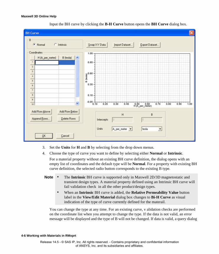
Maxwell 3D Online Help
Input the BH curve by clicking the B-H Curve button opens the BH Curve dialog box.
3. Set the Units for H and B by selecting from the drop down menus.
4. Choose the type of curve you want to define by selecting either Normal or Intrinsic.
For a material property without an existing BH curve definition, the dialog opens with an empty list of coordinates and the default type will be Normal. For a property with existing BH curve definition, the selected radio button corresponds to the existing B type.
You can change the type at any time. For an existing curve, v alidation checks are performed on the coordinate list when you attempt to change the type. If the data is not valid, an error message will be displayed and the type of B will not be changed. If data is valid, a query dialog
Note • The Intrinsic BH curve is supported only in Maxwell 2D/3D magnetostatic and transient design types. A material property defined using an Intrinsic BH curve will fail validation check in all the other product/design types.
• When an Intrinsic BH curve is added, the Relative Permeability Value button label in the View/Edit Material dialog box changes to Bi-H Curve as visual indication of the type of curve currently defined for the materail.
4-6 Working with Materials in RMxprt
Release 14.5 - © SAS IP, Inc. All rights reserved. - Contains proprietary and confidential information of ANSYS, Inc. and its subsidiaries and affiliates.

Maxwell 3D Online Help
box displays asking if the coordinates should be converted.
Pressing No can be used, fer example, when users have specified the BH coordinates and then realize they haven't select the desired type.
5. Enter B and H values in each row of the Coordinates table. Placing the cursor in a table cell enables the Add Row Above, Add Row Below, and Delete Rows buttons.
Note the following requirements for creating a valid curve:
• For a Normal BH curve, the slope of the curve can not be less than that of free space any-where along the curve.
• For an Intrinsic BH curve, the slope of the curve can not be less than 0.
• The value of B must increase along the curve.
• The initial value of B must be 0 (zero).
As you enter values, the graph is updated.
To Add or Edit rows, you can click the following buttons:
• Add Row Above
• Add Row Below
• Append Rows (to specify the number of rows to append to the table)
• Delete Rows
Optionally, click Import Dataset to import BH curve data from a file, and if they are in the wrong columns, click Swap X-Y Data to switch the B values and H values in the graphics dis-play. You can also use the SheetScan tool to extract curve data from sources such as manufac-turer datasheets to a dataset, which can then be exported to a tab-delimited file, and imported via Import Dataset. (Refer to Adding Datasets and Exporting Datasets for related information on working with datasets. Refer to Using SheetScan for working with the SheetScan tool.)
Note Changing the type of the BH curve invalidates all solution data
Working with Materials in RMxprt 4-7
Release 14.5 - © SAS IP, Inc. All rights reserved. - Contains proprietary and confidential information of ANSYS, Inc. and its subsidiaries and affiliates.
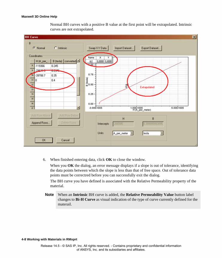
Maxwell 3D Online Help
Normal BH curves with a positive B value at the first point will be extrapolated. Intrinsic curves are not extrapolated.
6. When finished entering data, click OK to close the window.
When you OK the dialog, an error message displays if a slope is out of tolerance, identifying the data points between which the slope is less than that of free space. Out of tolerance data points must be correctred before you can successfully exit the dialog.
The BH curve you have defined is associated with the Relative Permeability property of the material.
Note When an Intrinsic BH curve is added, the Relative Permeability Value button label changes to Bi-H Curve as visual indication of the type of curve currently defined for the materail.
4-8 Working with Materials in RMxprt
Release 14.5 - © SAS IP, Inc. All rights reserved. - Contains proprietary and confidential information of ANSYS, Inc. and its subsidiaries and affiliates.

Maxwell 3D Online Help
Bulk Conductivity for an RMxprt MaterialSpecify the following for bulk conductivity and specify the units:
Dielectric Loss Tangent for RMxprt MaterialSpecify the following for dielectric loss tangent.
Type Value
Simple Type a value for the Bulk Conductivity.
Anisotropic The following two parameters appear:
• T(1,1)
• T(2,2)
You can specify a Simple or Nonlinear type for each of these parameters.
Note The Anisotropic type is not used in RMxprt designs.
Type Value
Simple Type a value for the Bulk Conductivity.
Anisotropic The following two parameters appear:
• T(1,1)
• T(2,2)
Type a simple value for each.
Note This property is not used in RMxprt design analysis, but it will be transferred to Maxwell 3D Design automatically when the design is created by RMxprt.
Working with Materials in RMxprt 4-9
Release 14.5 - © SAS IP, Inc. All rights reserved. - Contains proprietary and confidential information of ANSYS, Inc. and its subsidiaries and affiliates.

Maxwell 3D Online Help
Magnetic Loss Tangent for RMxprt Material
Magnetic Coercivity for Maxwell and RMxprt MaterialsSpecify the following for magnetic coercivity and specify the units:
Core Loss Type for an RMxprt MaterialSpecify the following for core loss type and specify the units:
Type Value
Simple Type a value for the Bulk Conductivity.
Anisotropic The following two parameters appear:
• T(1,1)
• T(2,2)
Type a simple value for each.
Note This property is not used in RMxprt design analysis, but it will be transferred to Maxwell 3D Design automatically when the design is created by RMxprt.
Type Value
Vector Appears by default.
• If the Relative Permeability Type is either Simple or Anisotropic,enter a Value for the Magnitude.
• If the Relative Permeability Type is Nonlinear, Magnitude becomes uneditable, and three additional fields of Type Unit Vector: X Component, Y Component, and Z Component appear in which you can enter values or specify functions.
Name Value
4-10 Working with Materials in RMxprt
Release 14.5 - © SAS IP, Inc. All rights reserved. - Contains proprietary and confidential information of ANSYS, Inc. and its subsidiaries and affiliates.

Maxwell 3D Online Help
Calculating Properties for Core Loss in RMxprt (BP Curve)To be able to extract parameters from the loss characteristics (B-P Curve), you first set the Core Loss Type of the material to Electrical Steel (rather than None or Power Ferrite) as a material prop-erty in the View / Edit Material window.
To calculate core loss properties for an electrical steel material:
1. Click Tools>Edit Configured Libraries>Materials.
• Or in the project tree, you can also right-click Materials, and select Edit All Libraries.
The Edit Libraries window appears.
2. Click Add Material.The View/Edit Material window appears.
3. In the Core Loss Type row, select Electrical Steel from the Value pull-down list.
This enables the Calculate Properties for pull-down menu at the bottom of the dialogue box with the following two choices:
• Calculate Properties for: Core Loss at One Frequency
• Calculate Properties for: Core Loss versus Frequency
It also displays parameters associated with Electrical Steel materials.
None No core loss is to be calculated for this material.
Electrical Steel The following parameters appear:
• Kh: Hysteresis
• Kc: Classical Eddy
• Ke: Excess
Selecting Electrical Steel also enables the Calculate Properties for Core Loss Coefficient the pull-down list at the bottom of the dialog box. Selecting the Core Loss Coefficient opens the BP Curve window.
Power Ferrite The following parameters appear:
• Cm
• X
• Y
Selecting Power Ferrite also enables the Calculate Properties for Core Loss versus Frequency pull-down list at the bottom of the dialog box. Selecting the Core Loss versus Frequency opens the BP Curve window.
Working with Materials in RMxprt 4-11
Release 14.5 - © SAS IP, Inc. All rights reserved. - Contains proprietary and confidential information of ANSYS, Inc. and its subsidiaries and affiliates.

Maxwell 3D Online Help
Electrical Steel Core Loss from a Single-Frequency Loss Curve
With the Core Loss Type set to Electrical Steel:
1. Select Core Loss at One Frequency from the Calculate Properties for: pull-down menu.
The BP Curve window appears.
2. Do one of the following to specify a BP curve:
• Import the curve from a saved file.
• Enter the coordinates manually.
3. Select the units in which the B-P curve is measured from the Core Loss Unit pull-down list.
4. Type values and select units for the following:
• Mass Density
• Frequency
• Thickness
• Conductivity
The following parameters are dynamically updated with both the specified unit and the stan-dard unit (w/m^3) as the input data changes.
• Kh -Hysteresis
• Kc - Classical Eddy
• Ke - Excess
5. Click OK.
The View/Edit Material dialog box reappears. The property values fro Kh, Kc, and Ke are updated as new default values.
Computation of Core Loss from a Single-Frequency Loss Curve
The principles of the computation algorithm are summarized as follows.
The iron-core loss is expressed as:
Note The accuracy in inputting the data for B-P Curve for the electrical steel material has significant effect on the correctness of the analyses to the electromagnetic characteristics of the electric machine. You should input the data for B-P Curve according to the accurate data provided by the manufacturers of materials.
pv ph pc pe+ +=
K1Bm2
K2Bm1.5
+=
4-12 Working with Materials in RMxprt
Release 14.5 - © SAS IP, Inc. All rights reserved. - Contains proprietary and confidential information of ANSYS, Inc. and its subsidiaries and affiliates.

Maxwell 3D Online Help
where the eddy-current loss is
the hysteresis loss is
and the excessive loss is
Therefore
The classical eddy-current loss coefficient is calculated directly as
where σ is the conductivity and d is the thickness of one lamination sheets.
Minimize the quadratic form to obtain K1 and K2.
where Pvi , Bmi – the i-th point of the data on the loss characteristics curve.
The other two loss coefficients are obtained as
pc kc fBm( )2=
ph knfBm2
=
pe ke fBm( )1.5=
K1 kh f Kc f2
+=
K2 ke f1.5
=
kc π2σd2
δ------=
err K1 K2,( ) pvi K1B2mi K2B
1.5mi+
–2
i min= =
Working with Materials in RMxprt 4-13
Release 14.5 - © SAS IP, Inc. All rights reserved. - Contains proprietary and confidential information of ANSYS, Inc. and its subsidiaries and affiliates.

Maxwell 3D Online Help
where f0 is the testing frequency for B-H Curve.
Related Topics:
Calculating Properties for Core Loss (BP Curve) for Maxwell
Core Loss Coefficients for Electrical Steel
Core Loss Coefficient Extraction
Core Loss Type for a Maxwell Material
kh
K1 kc f20–
f0---------------------------=
ke
K2
f1.50
------------=
4-14 Working with Materials in RMxprt
Release 14.5 - © SAS IP, Inc. All rights reserved. - Contains proprietary and confidential information of ANSYS, Inc. and its subsidiaries and affiliates.
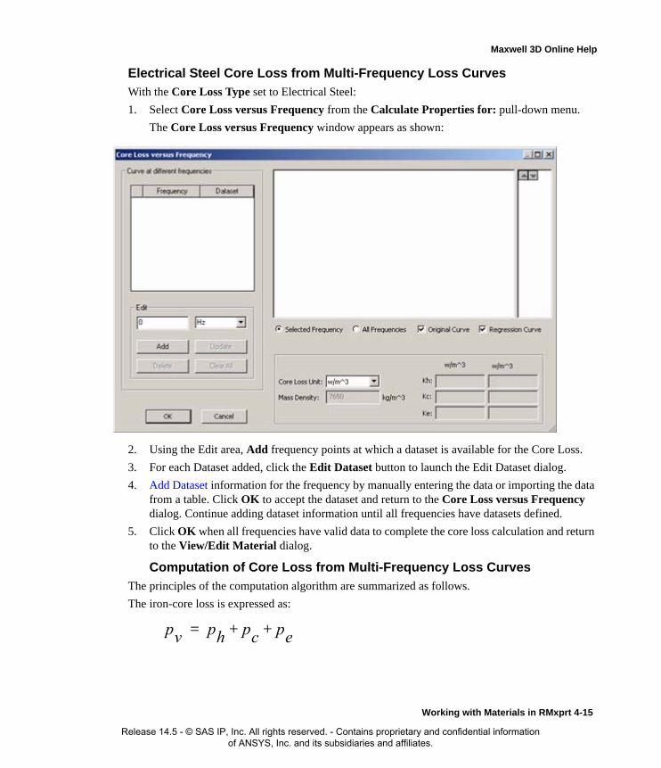
Maxwell 3D Online Help
Electrical Steel Core Loss from Multi-Frequency Loss Curves
With the Core Loss Type set to Electrical Steel:
1. Select Core Loss versus Frequency from the Calculate Properties for: pull-down menu.
The Core Loss versus Frequency window appears as shown:
2. Using the Edit area, Add frequency points at which a dataset is available for the Core Loss.
3. For each Dataset added, click the Edit Dataset button to launch the Edit Dataset dialog.
4. Add Dataset information for the frequency by manually entering the data or importing the data from a table. Click OK to accept the dataset and return to the Core Loss versus Frequency dialog. Continue adding dataset information until all frequencies have datasets defined.
5. Click OK when all frequencies have valid data to complete the core loss calculation and return to the View/Edit Material dialog.
Computation of Core Loss from Multi-Frequency Loss Curves
The principles of the computation algorithm are summarized as follows.
The iron-core loss is expressed as:
pv ph pc pe+ +=
Working with Materials in RMxprt 4-15
Release 14.5 - © SAS IP, Inc. All rights reserved. - Contains proprietary and confidential information of ANSYS, Inc. and its subsidiaries and affiliates.

Maxwell 3D Online Help
Minimize the quadratic form to obtain kh , kc and ke directly.
where m - the number of loss curves, ni - the number of points of the i-th loss curve, and Pvij = f(fi , Bmij) - two dimensional lookup table for multi-frequency loss curves.
Power Ferrite Core Loss from Multi-Frequency Loss CurvesWith the Core Loss Type set to Power Ferrite:
1. Select Core Loss versus Frequency from the Calculate Properties for: pull-down menu.
The Core Loss versus Frequency window appears as shown:
2. Using the Edit area, Add frequency points at which a dataset is available for the Core Loss.
3. For each Dataset added, click the Edit Dataset button to launch the Edit Dataset dialog.
4. Add Dataset information for the frequency by manually entering the data or importing the data from a table. Click OK to accept the dataset and return to the Core Loss versus Frequency
khfBm2
kc fBm( )2 ke fBm( )1.5+ +=
err kh kc ke, ,( ) pvij kh fiB2mij kc f
2i B
2mij ke f
1.5i B
1.5mij+ +
–2
j 1=
ni
i 1=
m
min= =
4-16 Working with Materials in RMxprt
Release 14.5 - © SAS IP, Inc. All rights reserved. - Contains proprietary and confidential information of ANSYS, Inc. and its subsidiaries and affiliates.
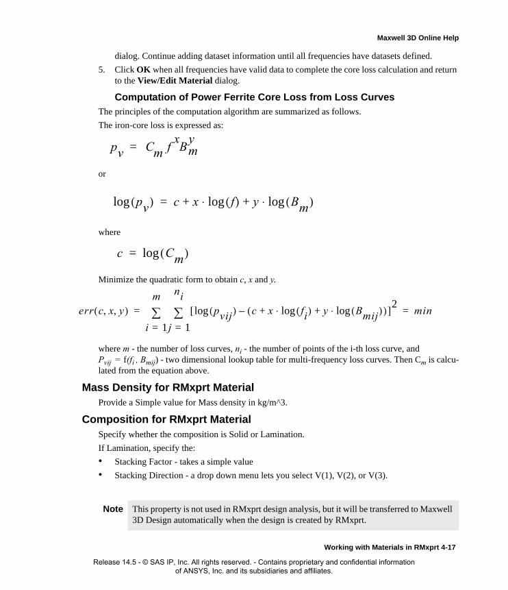
Maxwell 3D Online Help
dialog. Continue adding dataset information until all frequencies have datasets defined.
5. Click OK when all frequencies have valid data to complete the core loss calculation and return to the View/Edit Material dialog.
Computation of Power Ferrite Core Loss from Loss Curves
The principles of the computation algorithm are summarized as follows.
The iron-core loss is expressed as:
or
where
Minimize the quadratic form to obtain c, x and y.
where m - the number of loss curves, ni - the number of points of the i-th loss curve, and Pvij = f(fi , Bmij) - two dimensional lookup table for multi-frequency loss curves. Then Cm is calcu-lated from the equation above.
Mass Density for RMxprt MaterialProvide a Simple value for Mass density in kg/m^3.
Composition for RMxprt MaterialSpecify whether the composition is Solid or Lamination.
If Lamination, specify the:
• Stacking Factor - takes a simple value
• Stacking Direction - a drop down menu lets you select V(1), V(2), or V(3).
Note This property is not used in RMxprt design analysis, but it will be transferred to Maxwell 3D Design automatically when the design is created by RMxprt.
pv Cm fxB
ym=
pv( )log c x f( )log⋅ y Bm( )log⋅+ +=
c Cm( )log=
err c x y, ,( ) pvij( )log c x fi( )log⋅ y Bmij( )log⋅+ +( )–[ ]2
j 1=
ni
i 1=
m
min= =
Working with Materials in RMxprt 4-17
Release 14.5 - © SAS IP, Inc. All rights reserved. - Contains proprietary and confidential information of ANSYS, Inc. and its subsidiaries and affiliates.

Maxwell 3D Online Help
Permanent Magnet Materials in RMxprtA permanent magnet is defined as a material that generates a magnetic flux due to permanent mag-netic dipoles in that material.
Nonlinear vs. Linear Permanent MagnetsIn general, permanent magnets are nonlinear and should be modeled via a B-H curve as shown below. The magnetic coercivity, Hc, is defined as the B-H curve's H-axis intercept, and the mag-netic remanence, Br, as its B-axis intercept.
In many applications, however, the permanent magnet's behavior can be approximated using a lin-ear relationship between B and H. In these cases, there is no need to create a nonlinear material. Simply enter the appropriate values of Br or Hc for the material when defining its properties.
Compute Remanent Br from B-H curve
The value of the remanent Br of the individual element after the magnetization field is computed is determined in such a way: after having located the operating point on the original non-remanent B-H curve, draw a line which is parallel to the original recoil curve with the slope of and passes the operating point, the intersection of this line with B-axis is the remanent Br as the result of the applied magnetization field.
Linear Permanent Magnet
B
H
Br
Hc
Nonlinear Permanent Magnet
μ0μr
4-18 Working with Materials in RMxprt
Release 14.5 - © SAS IP, Inc. All rights reserved. - Contains proprietary and confidential information of ANSYS, Inc. and its subsidiaries and affiliates.

Maxwell 3D Online Help
Calculating the Properties for a Non-Linear Permanent Magnet in RMxprtNon-linear permanent magnet properties may be specified in one of two ways.
First, a BH curve may be input directly as follows:
1. Click the View/Edit Materials… button in the Edit Libraries dialog box.
The View/Edit Material dialog box appears.
2. The nonlinear BH curve is defined by setting the Relative Permeability Type either to Non-
0.0 2000.0 4000.0 6000.0 8000.0 10000.0H [A/m]
0.00
0.20
0.40
0.60
0.80
1.00
1.20
1.40
1.60
1.80
2.00B
[T]
Ansoft LLC Steel_1010 ANSOFT
Working with Materials in RMxprt 4-19
Release 14.5 - © SAS IP, Inc. All rights reserved. - Contains proprietary and confidential information of ANSYS, Inc. and its subsidiaries and affiliates.

Maxwell 3D Online Help
linear or Anisotropic.
If you select Anisotropic, each of its components can be selected Nonlinear and can be speci-fied by a BH Curve.
A B-H Curve button appears in the nonlinear property’s Value column
3. Input the BH curve by clicking the B-H Curve button in the property Value column.
This opens the BH Curve dialog box in which you can input (or modify) curve data. (Refer to Adding Datasets for general information on working with datasets.
4-20 Working with Materials in RMxprt
Release 14.5 - © SAS IP, Inc. All rights reserved. - Contains proprietary and confidential information of ANSYS, Inc. and its subsidiaries and affiliates.

Maxwell 3D Online Help
• For a Normal BH curve, the slope of the curve can not be less than that of free space any-where along the curve.
• For an Intrinsic BH curve, the slope of the curve can not be less than 0.
When you OK the dialog, an error message displays if a slope is out of tolerance, identifying the data points between which the slope is less than that of free space.
The operations to input a nonlinear demagnetization curve are the same as entering a BH curve for Steel material. When a BH curve goes through the second quadrant or third quadrant, the curve is treated as a demagnetization curve.
4. To model temperature dependency for a nonlinear permanent magnet you must:
• Use an Intrinsic BH curve to model the Relative Permeability
Note • The Intrinsic BH curve is supported only in Maxwell 2D/3D magnetostatic and transient design types. A material property defined using an Intrinsic BH curve will fail validation check in all the other product/design types.
• When an Intrinsic BH curve is added, the Relative Permeability Value button label changes to Bi-H Curve as visual indication of the type of curve currently defined for the materail.
Working with Materials in RMxprt 4-21
Release 14.5 - © SAS IP, Inc. All rights reserved. - Contains proprietary and confidential information of ANSYS, Inc. and its subsidiaries and affiliates.

Maxwell 3D Online Help
• Specify a Thermal Modifier for both Relative Permeability and the Magnitude of Mag-netic Coercivity. Apply a thermal Modifier by selecting the Thermal Modifier check-box. Checking this box causes the Thermal Modifier column to display at the right side of the Properties of the Material table. Selecting Edit rather than None causes display of the Edit Thermal Modifier dialog.
Alternatively, a non-linear BH curve can be modeled by the following four parameters:
• residual flux density Br
• coercive field force Hc
• maximum energy product (BH)max
• relative recoil permeability μr
From the View/Edit Materials window:
1. Set the Relative Permeability to Nonlinear.
This enables the Calculate Properties for... drop down menu at the bottom of the window.
2. Click Non-Linear Permanent Magnet from the drop down menu.
This displays the Properties for Non-Linear Permanent Magnet dialog box, which contains
4-22 Working with Materials in RMxprt
Release 14.5 - © SAS IP, Inc. All rights reserved. - Contains proprietary and confidential information of ANSYS, Inc. and its subsidiaries and affiliates.

Maxwell 3D Online Help
the following fields into which you enter the appropriate values.
3. Click OK to close the dialogue and return to the View/Edit Materials window.
The values for Relative Permeability and Magnitude under Magnetic Coercivity are updated as new default values. Maxwell will create a lookup table based on the Four-Parameter Curve Fitting algorithm, and update the coordinates of the BH curve automatically as long as the input data of four parameters pass the validation check.
Related Topics
Non-Linear vs. Linear Permanent Magnets
Calculating the Properties for a Linear Permanent Magnet
Temperature Dependent Nonlinear Permanent Magnets
Calculating the Properties for a Linear Permanent MagnetEdit a linear demagnetization curve is simple. From the View/Edit Materials window:
1. Set the Relative Permeability to Simple.
This enables the Calculate Properties for Permanent Magnet drop down menu at the bottom of the window.
2. Click Permanent Magnet from the drop down menu.
This displays the Properties for Permanent Magnet window. This contains the following fields.
Mur Provide a value for relative permeability.
Hc Coercive field force Hc in the units specified. Provide a value and select units from the drop down menu.
Br Residual flux density Br, in Tesla.
If enabled, provide a value and select units from the drop down menu.
BHmax Maximum magnetic energy product (BH)max
If enabled, provide a value and select units form the drop down menu.
Mu (enabled by default) Provide a value.
Hc (enabled by default) Coercive field force Hc in the units specified. Provide a value and select units from the drop down menu.
Working with Materials in RMxprt 4-23
Release 14.5 - © SAS IP, Inc. All rights reserved. - Contains proprietary and confidential information of ANSYS, Inc. and its subsidiaries and affiliates.

Maxwell 3D Online Help
3. Click OK to close the dialogue and return to the View/Edit Materials window.
The values for Relative Permeability and Magnitude under Magnetic Coercivity are updated as new default values.
Using Demagnetization CurvesMany permanent magnet manufactures directly provide demagnetization curves for their products, but in most cases, manufactures provide some main parameters, such as residual flux density Br, coercive field force Hc and maximum magnetic energy product (BH)max, and relative recoil mag-netic permeability μr. This section and the next section describe the basic parameters for the demagnetization curve of permanent magnets and the curve fitting based on these parameters.
Hysteresis LoopThe permanent-magnetic material belongs to hard-magnetic material. It is characterized with "fat" hysteresis loop, which encloses large area as shown in the figure. When magnetized, it keeps high magnetic property with the external magnetic field removed, therefore is used in the permanent-magnet electric machine to produce magnetic field. The characteristics of the permanent-magnetic material are represented with its main parameters: residual flux density Br, coercive field force Hc and maximum magnetic energy product (BH)max.
Br/Mp (disabled by default) Checking this enables the radio buttons that let you specify either Br or Mp.
Br Residual flux density Br, in Tesla.
If enabled, provide a value and select units from the drop down menu.
Mp If enabled, provide a value and select units form the drop down menu.
Note The accuracy in inputting the characteristic parameters for the permanent-magnetic material has significant effect on the correctness of the analyses to the electromagnetic characteristics of the electric machine. It is suggested that users should input the characteristic parameters of the permanent-magnetic material according to the accurate data provided by the manufacturers of materials. RMxprt provides a few characteristic parameters of permanent-magnetic materials for reference.
4-24 Working with Materials in RMxprt
Release 14.5 - © SAS IP, Inc. All rights reserved. - Contains proprietary and confidential information of ANSYS, Inc. and its subsidiaries and affiliates.

Maxwell 3D Online Help
Demagnetization Curve
The part of the maximum hysteresis loop of the permanent-magnetic material in the second quad-rant is called the demagnetization curve as shown in the next figure. It is the basic characteristics curve of the permanent-magnetic material. On the demagnetization curve, the magnetic flux den-sity has positive values, but the magnetic field intensity has negative values. It means that the per-manent-magnetic material is applied with demagnetization magnetic field intensity. Since Hm and Bm are in opposite directions, when the magnetic flux goes through the permanent-magnetic mate-rial, the magnetic potential difference along the direction of the magnetic flux does not drop, but
Working with Materials in RMxprt 4-25
Release 14.5 - © SAS IP, Inc. All rights reserved. - Contains proprietary and confidential information of ANSYS, Inc. and its subsidiaries and affiliates.

Maxwell 3D Online Help
rises. Therefore, the permanent-magnetic material is a magnetic source, similar to the electric source in the electric circuit.
The two extreme positions on the demagnetization curve are the two significant parameters to rep-resent the magnetic characteristics of the permanent-magnetic material. On the demagnetization curve, the value of the magnetic flux density corresponding to zero magnetic field intensity H is termed residual flux density Br, on the other hand, the value of the magnetic field intensity corre-sponding to zero magnetic flux density B is termed coercive field force Hc. The produce of the magnetic flux density and the magnetic field intensity at any point on the demagnetization curve is termed magnetic energy product (BH), which is proportional to the magnetic energy density pos-sessed by the permanent magnet at the given operating situation. At the two extreme positions (B = Br, H = 0) and (B = 0, H = Hc), the magnetic energy product is equal to zero. Somewhere at an intermediate position, the magnetic energy reaches its maximum value and is termed maximum magnetic energy product (BH)max, which is another significant parameter to represent the magnetic characteristics of the permanent-magnetic material. To some permanent-magnetic materials with linear demagnetization curve, it is obvious that at (B = Br / 2, H = Hc / 2), the magnetic energy product reaches its maximum value, i.e. (BH)max = Br Hc / 4.
Recoil Lines
The relationship between the magnetic flux density and the magnetic field intensity represented by the demagnetization curve only exists when the magnetic field intensity varies in the same direc-tion. In fact, when the permanent magnet electric machine is working, the demagnetization field intensity varies repeatedly in both directions. When demagnetization field is applied to the magne-
4-26 Working with Materials in RMxprt
Release 14.5 - © SAS IP, Inc. All rights reserved. - Contains proprietary and confidential information of ANSYS, Inc. and its subsidiaries and affiliates.

Maxwell 3D Online Help
tized permanent magnet, the magnetic flux density decreases along the curly segment BrP on the demagnetization curve as shown in the figure
If the external demagnetization field intensity Hp is removed when the magnetic flux density reaches the point P, the magnetic flux density will increase not along the original demagnetization curve, but along another curve PVR. If the external demagnetization field intensity is reapplied, the magnetic flux density will decrease along the new curve RUP. By repeatedly applying the demag-netization field intensity, a localized loop is formed and is termed local hysteresis loop. On the local hysteresis loop, the rising segment and the dropping segment are quite close to each other, therefore can be approximated by the straight line PR, which is termed recoil line with P as the starting point. If demagnetization field with intensity Hq not exceeding the original value Hp is applied thereafter, the magnetic flux density will vary reversibly along the recoil line PR. If Hq > Hp, the magnetic flux density drops to a new starting point Q. It will vary along the new recoil line QS, but not the previous one PR. This sort of irreversible variation in magnetic flux density causes instability in the characteristics of electric machines and complicates the design computation of permanent magnet electric machines, therefore should be avoided as possible.
Recoil Magnetic PermeabilityThe ratio of the average slope of the recoil line to the magnetic permeability in vacuum μ0 (μ0= 4 x 10⁻⁷ H/m) is termed relative recoil magnetic permeability or recoil magnetic permeability for short, μr:
H
B1
0r Δ
Δ=μ
μ
Working with Materials in RMxprt 4-27
Release 14.5 - © SAS IP, Inc. All rights reserved. - Contains proprietary and confidential information of ANSYS, Inc. and its subsidiaries and affiliates.

Maxwell 3D Online Help
If the demagnetization curve is curly, the value of μr depends on the location of the starting point and is a variable, but typically varies within a small range. Therefore, it is approximated as a con-stant and is taken as the slop of the tangent to the point (Br, 0) on the demagnetization curve. In other words, the recoil lines at different starting points are approximated as a family of parallel lines, which are all parallel to the tangent to the point (Br, 0) on the demagnetization curve.
Inflection Point
Some permanent-magnetic materials, such as some ferrite permanent-magnetic materials, show straight upper segment on the demagnetization curve. When the demagnetization field intensity drops to a given value, the demagnetization curve turns to decrease rapidly. The turning point is termed inflection point. If the demagnetization field intensity does not exceed the inflection point k, the recoil line coincides with the straight segment on the demagnetization curve. If the demagneti-zation field intensity exceeds the inflection point k, the new recoil line RP no longer coincides with the straight segment on the demagnetization curve.
Some permanent-magnetic materials, such as most of the rare-earth permanent-magnetic materials, show straight demagnetization curve in the whole range. In those cases, the recoil line coincides with the demagnetization curve. This makes the magnetic property keep stable while the perma-nent-magnet electric machine is working. This is the best ideal demagnetization curve for electric machine applications.
Curve Fitting of Demagnetization CurvesRMxprt fits the demagnetization curve according to the given characteristic parameters Br, Hc, (BH)max and μr.
4-28 Working with Materials in RMxprt
Release 14.5 - © SAS IP, Inc. All rights reserved. - Contains proprietary and confidential information of ANSYS, Inc. and its subsidiaries and affiliates.

Maxwell 3D Online Help
Three Parameter Curve Fitting
Given the three characteristic parameters Br, Hc and (BH)max, the principles of the three-parameter curve fitting algorithm are summarized as follows.Using the following figure as a reference:
and
where a<1.
Any magnetic flux density B in the interval
corresponds to the magnetic field intensity H:
Ha
Hca
-------=
Ba
Bra
------=
0 B Br≤ ≤
H H– c
Ha Hc–
Ba B–--------------------B+ H– c
Hc 1 a–( )
Br aB–------------------------B+ H– c
Br B–
Br aB–-------------------= = =
Working with Materials in RMxprt 4-29
Release 14.5 - © SAS IP, Inc. All rights reserved. - Contains proprietary and confidential information of ANSYS, Inc. and its subsidiaries and affiliates.

Maxwell 3D Online Help
The tangent at any point is given by:
The magnetic flux density Bm and the magnetic field intensity Hm corresponding to the maximum magnetic energy product satisfy the following relationship:
Solving yields:
Let the magnetic energy product at the point equal to (BH)max be:
Solving yields:
dBdH-------
dHdB------- 1–
1 aBBr------–
2
1 a–-----------------------------
BrHc-------= =
dBdH-------
B Bm=
BrHc-------=
Bm
Br
1 1 a–+-------------------------= and Hm
Hc
1 1 a–+-------------------------–=
BmHm
BrHc
1 1 a–+( )2
--------------------------------- BH( )max= =
a 2BrHc
BH( )max------------------------
BrHcBH( )max
------------------------–=
4-30 Working with Materials in RMxprt
Release 14.5 - © SAS IP, Inc. All rights reserved. - Contains proprietary and confidential information of ANSYS, Inc. and its subsidiaries and affiliates.

Maxwell 3D Online Help
The relative recoil magnetic permeability μr is calculated as:
Four Parameter Curve Fitting
The three-parameter curve fitting technique fits the demagnetization curve well. For the nonlinear permanent-magnetic material, the real operating point lies often not on the demagnetization curve, but on the recoil line. The relative recoil magnetic permeability calculated with the three-parameter curve fitting technique will cause deviation, therefore RMxprt employs a more accurate fitting technique: four-parameter curve fitting technique, as introduced below.
Given the four characteristic parameters Br, Hc, (BH)max and μr, the principles of the four-parame-ter curve fitting algorithm are summarized as follows:
1. Draw a line through the point (0, Br) with the slope equal to -μrμo as shown in the Figure. The segment of this line in the second quadrant is termed the ideal recoil line.
2. Find the virtual magnetic flux density Br0.
3. With Br0, Hc, and (BH)max, draw the demagnetization curve with the three-parameter curve fit-ting technique. The curve should touch the ideal recoil line at the tangent point (Ht, Bt).
4. Any magnetic flux density B in the interval
μr1
μ0------ dB
dH-------
B Br=1 a–( )
Brμ0Hc--------------= =
0 B Br≤ ≤
Working with Materials in RMxprt 4-31
Release 14.5 - © SAS IP, Inc. All rights reserved. - Contains proprietary and confidential information of ANSYS, Inc. and its subsidiaries and affiliates.

Maxwell 3D Online Help
corresponds to the magnetic field intensity H:
The virtual magnetic flux density Br0 is found by iteration:
1. Start from the initial guess for the lower and the upper bounds for the virtual magnetic flux density Br0:
2. Let:
3. With Br0, Hc, and (BH)max, draw the demagnetization curve with the three-parameter curve fit-ting technique.
H
H– c
Br0 B–
Br0 aoB–------------------------- B Bt≤
Ht
B Bt–
μrμo---------------+ B Bt≥
=
B0 max μrμoHc
BH( )maxHc
------------------------,
=
B1 Br=
Br0
B0 B1+
2--------------------=
a0 2Br0HcBH( )max
------------------------Br0HcBH( )max
------------------------–=
4-32 Working with Materials in RMxprt
Release 14.5 - © SAS IP, Inc. All rights reserved. - Contains proprietary and confidential information of ANSYS, Inc. and its subsidiaries and affiliates.
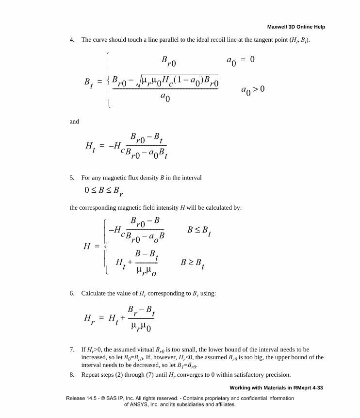
Maxwell 3D Online Help
4. The curve should touch a line parallel to the ideal recoil line at the tangent point (Ht, Bt).
and
5. For any magnetic flux density B in the interval
the corresponding magnetic field intensity H will be calculated by:
6. Calculate the value of Hr corresponding to Br using:
7. If Hr>0, the assumed virtual Br0 is too small, the lower bound of the interval needs to be increased, so let B0=Br0. If, however, Hr<0, the assumed Br0 is too big, the upper bound of the interval needs to be decreased, so let B1=Br0.
8. Repeat steps (2) through (7) until Hr converges to 0 within satisfactory precision.
Bt
Br0 a0 0=
Br0 μrμ0Hc 1 a0–( )Br0–
a0---------------------------------------------------------------------- a0 0>
=
Ht H– c
Br0 Bt–
Br0 a0Bt–---------------------------=
0 B Br≤ ≤
H
H– c
Br0 B–
Br0 aoB–------------------------- B Bt≤
Ht
B Bt–
μrμo---------------+ B Bt≥
=
Hr Ht
Br Bt–
μrμ0-----------------+=
Working with Materials in RMxprt 4-33
Release 14.5 - © SAS IP, Inc. All rights reserved. - Contains proprietary and confidential information of ANSYS, Inc. and its subsidiaries and affiliates.

Maxwell 3D Online Help
Conductor DataWhen a material is assigned to a machine part, RMxprt checks that the material is appropriate for the machine part based upon whether it is a conductor or other material type. RMxprt distinguishes conductors based on material threshold settings. RMxprt’s treatment of conductors may be set by the used by adjusting the Material Threshold.
Setting the Material Threshold for RMxprt1. Click RMxprt>Design Settings.
The Design Settings dialog box appears with the Material Threshold tab selected.
2. Type a value in the Conductivity Threshold text box (Default=100,000).
3. Type a value in the Permeability text box (Default=100).
4. If you want these values to be the default, change the values by clicking the Tools>Options>RMxprt Options menu and setting the material thresholds in the RMxprt Options dialog.
5. Click OK.
Editing Conductivity Properties in RMxprt1. Click Tools>Edit Configured Libraries>Materials to open the Edit Libraries dialog box.
2. Select the material in the list whose conductivity properties you wish to edit and click the View/Edit Materials button.
3. In the View/Edit Materials dialog, Bulk Conductivity has two property types in the Type pull-down list.
• Simple: For this type, you must enter a simple value for the property value.
• Anisotropic: For this type, you must specify material properties for three principal direc-tions:
a. T(1,1)
b. T(2,2)
c. T(3,3)
4. Mass Density is a Simple parameter.
Note RMxprt will treat materials with conductivity greater than 100,000 as conductors, and materials with Permeability greater than 100 as steels.
Note The Anisotropic type is not used in RMxprt design analysis, but it will be transferred to Maxwell 3D Design automatically when the design is created by RMxprt.
4-34 Working with Materials in RMxprt
Release 14.5 - © SAS IP, Inc. All rights reserved. - Contains proprietary and confidential information of ANSYS, Inc. and its subsidiaries and affiliates.

5
Specifying RMxprt Solution Settings
Specify how RMxprt computes a solution by adding a solution setup to the design. You can define more than one solution setup per design.
To add a solution setup to a design:
1. Select a design in the project tree.
2. Click RMxprt>Analysis Setup>Add Solution Setup.
• Alternatively, right-click Analysis in the project tree, and then click Add Solution Setup on the shortcut menu.
The Solution Setup dialog box appears. It is divided among the following tabs:
3. Click the General tab.
4. If available for the machine you are using, select an Operation Type from the pull-down list.
This may be Motor or Generator.
When you make the selection, this makes a difference in the Load Type available.
5. Select a Load Type from the pull-down list. For Motor operation, the options are:
• Const Speed
• Const Power
General Includes general solution settings, including rated output power, speed, operating temperature, etc.
<machine type> Includes settings specific to the selected machine type.
Defaults Includes settings to save and clear user-defined default values.
Note To enable selection of Generator for Adjust-Speed Synchronous Machines, the machine Control Type must be set to AC in its Properties window.
Specifying RMxprt Solution Settings 5-1
Release 14.5 - © SAS IP, Inc. All rights reserved. - Contains proprietary and confidential information of ANSYS, Inc. and its subsidiaries and affiliates.
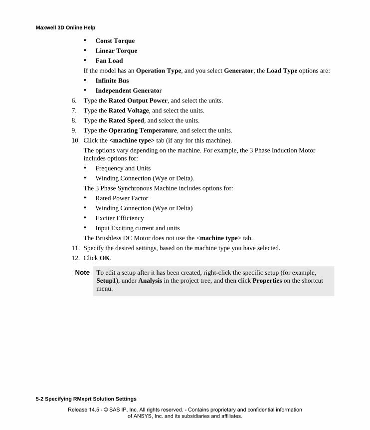
Maxwell 3D Online Help
• Const Torque
• Linear Torque
• Fan Load
If the model has an Operation Type, and you select Generator, the Load Type options are:
• Infinite Bus
• Independent Generator
6. Type the Rated Output Power, and select the units.
7. Type the Rated Voltage, and select the units.
8. Type the Rated Speed, and select the units.
9. Type the Operating Temperature, and select the units.
10. Click the <machine type> tab (if any for this machine).
The options vary depending on the machine. For example, the 3 Phase Induction Motor includes options for:
• Frequency and Units
• Winding Connection (Wye or Delta).
The 3 Phase Synchronous Machine includes options for:
• Rated Power Factor
• Winding Connection (Wye or Delta)
• Exciter Efficiency
• Input Exciting current and units
The Brushless DC Motor does not use the <machine type> tab.
11. Specify the desired settings, based on the machine type you have selected.
12. Click OK.
Note To edit a setup after it has been created, right-click the specific setup (for example, Setup1), under Analysis in the project tree, and then click Properties on the shortcut menu.
5-2 Specifying RMxprt Solution Settings
Release 14.5 - © SAS IP, Inc. All rights reserved. - Contains proprietary and confidential information of ANSYS, Inc. and its subsidiaries and affiliates.

Maxwell 3D Online Help
Generating a Custom Design Sheet for RMxprtRMxprt allows users to import all the data items of Design Output into a Microsoft Excel work-sheet in order for users to design Design Sheet of their own styles according to their own require-ments using Microsoft Excel.
Before you can specify a design sheet, you first need to customize a template in Microsoft Excel and set the export options.
To set the export options:
1. Click RMxprt>Design Settings.The Design Settings dialog box appears. Select the Export Options tab.
2. In the Design Sheet section, specify an Excel Template by clicking the ... button, selecting the template you want to use, and clicking Save.
3. Click OK.
To create a design sheet based on a previously-customized template after the design has been ana-lyzed:
1. Click RMxprt>Analysis Setup>Export.The Export dialog box appears.
2. Select Customized Design Sheet from the Type pull-down menu.
3. Choose the Solution Setup from the pull-down menu.
4. In the Path field, enter the location to export the files to, or use the ellipsis (...) button to browse to the desired location.
5. Click OK.
RMxprt will connect to Microsoft Excel according to the set path and automatically import the relevant data from Design Output into a copy of the customized Design Sheet Template. Specific data not available in Design Output is shown as N/A, for instance, RS in Slot Sizes is N/A (mm) when stop type is 1. The post-processing of data is automatically performed, for instance, Winding Weight is 0.947 (kg).
Related Topics:
Exporting a Maxwell or Simplorer Model
Key Words in Output Data for RMxprtIn Design Output of RMxprt, the literal expressions for various parameters are termed key words of output data. For example, the Design Output for Line-start Permanent-magnet Synchronous Motor (lssm) is shown below.
Note Several Design Sheet examples are shipped with RMxprt in the examples subdirectory of your installation.
Specifying RMxprt Solution Settings 5-3
Release 14.5 - © SAS IP, Inc. All rights reserved. - Contains proprietary and confidential information of ANSYS, Inc. and its subsidiaries and affiliates.

Maxwell 3D Online Help
In the Design Output, "Rated Output Power", "Rated Voltage", "Number of Poles", "Frequency", "Frictional Loss", etc. are all key words of output data. To resort to those key words into Microsoft Excel worksheet, the corresponding data in the Design Output should be import into the work-sheet.
5-4 Specifying RMxprt Solution Settings
Release 14.5 - © SAS IP, Inc. All rights reserved. - Contains proprietary and confidential information of ANSYS, Inc. and its subsidiaries and affiliates.

Maxwell 3D Online Help
Creating RMxprt Customized Design Sheet TemplateAs a sample example, the Line-start Permanent-magnet Synchronous Motor (lssm) is used to dem-onstrate the process for creating a Customized Design Sheet template.
Start Microsoft Excel, rename the blank worksheet file as "lssm" and save it under the path ansoft\rmxprt5 as shown below.
Design Template of Microsoft Excel Worksheet in Preferred StylesAccording to special requirements and preferences, select relevant parameters, arrange the page formats of worksheet. Taking as example a part of the parameters of the Design Sheet of the Line-start Permanent-magnet Synchronous Motor (lssm), the designed worksheet template is shown below.
Specifying RMxprt Solution Settings 5-5
Release 14.5 - © SAS IP, Inc. All rights reserved. - Contains proprietary and confidential information of ANSYS, Inc. and its subsidiaries and affiliates.

Maxwell 3D Online Help
In the template, the yellow-colored areas are reserved for importing data.
Resort to Key Words in Design OutputIn the spaces for importing data in the template (shown in yellow), key in = "xxxxx". Within the double quotation marks, xxxxx stands for the relevant key words as shown below.
5-6 Specifying RMxprt Solution Settings
Release 14.5 - © SAS IP, Inc. All rights reserved. - Contains proprietary and confidential information of ANSYS, Inc. and its subsidiaries and affiliates.
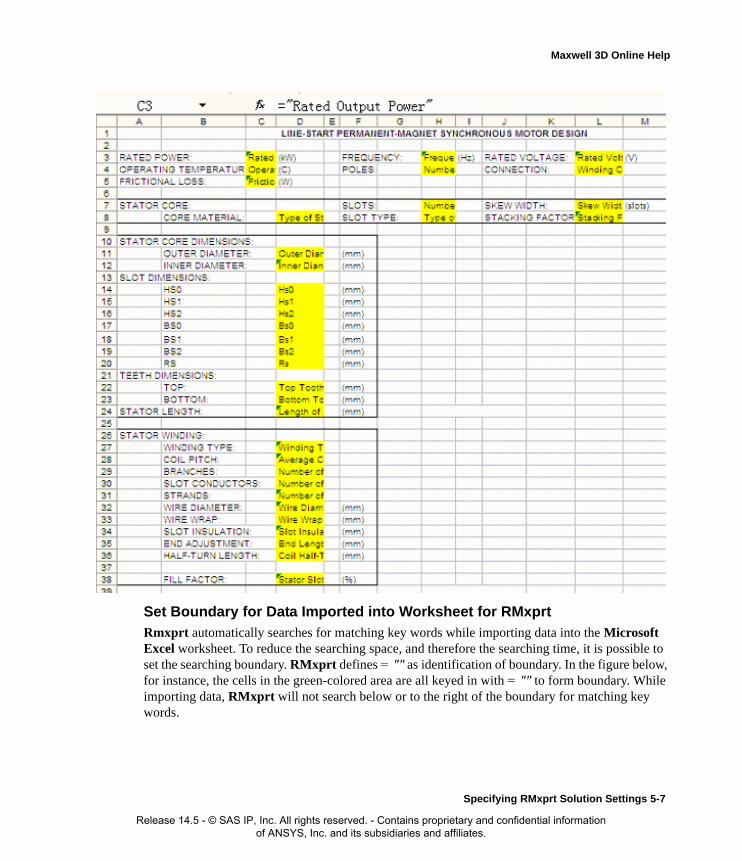
Maxwell 3D Online Help
Set Boundary for Data Imported into Worksheet for RMxprtRmxprt automatically searches for matching key words while importing data into the Microsoft Excel worksheet. To reduce the searching space, and therefore the searching time, it is possible to set the searching boundary. RMxprt defines = "" as identification of boundary. In the figure below, for instance, the cells in the green-colored area are all keyed in with = "" to form boundary. While importing data, RMxprt will not search below or to the right of the boundary for matching key words.
Specifying RMxprt Solution Settings 5-7
Release 14.5 - © SAS IP, Inc. All rights reserved. - Contains proprietary and confidential information of ANSYS, Inc. and its subsidiaries and affiliates.
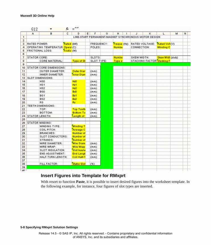
Maxwell 3D Online Help
Insert Figures into Template for RMxprtWith resort to function Paste, it is possible to insert desired figures into the worksheet template. In the following example, for instance, four figures of slot types are inserted.
5-8 Specifying RMxprt Solution Settings
Release 14.5 - © SAS IP, Inc. All rights reserved. - Contains proprietary and confidential information of ANSYS, Inc. and its subsidiaries and affiliates.

Maxwell 3D Online Help
Use Different Languages for RMxprt Design SheetsIt is possible to use a preferred language other than English in the Microsoft Excel worksheet tem-plate. In the following example, for instance, Simplified Chinese is used.
Specifying RMxprt Solution Settings 5-9
Release 14.5 - © SAS IP, Inc. All rights reserved. - Contains proprietary and confidential information of ANSYS, Inc. and its subsidiaries and affiliates.

Maxwell 3D Online Help
Post-process Data for RMxprtUsing the relevant functions of Microsoft Excel, it is possible to post-process data in the worksheet template. For example, calculate the weight of a winding using the following formula:
Note Key words are not allowed to be expressed in other languages.
5-10 Specifying RMxprt Solution Settings
Release 14.5 - © SAS IP, Inc. All rights reserved. - Contains proprietary and confidential information of ANSYS, Inc. and its subsidiaries and affiliates.

Maxwell 3D Online Help
In the following figure, the formula is entered into the relevant cell as:
=H7*D30*D31*D36*3.14*D32*D32*0.0078/4
wireofweightspecificwireofareasectional
coilofturnshalfoflengthwiresparallelofnumber
slotperconductorsofnumberslotsofnumberweightwinding
××××
×=
Specifying RMxprt Solution Settings 5-11
Release 14.5 - © SAS IP, Inc. All rights reserved. - Contains proprietary and confidential information of ANSYS, Inc. and its subsidiaries and affiliates.

Maxwell 3D Online Help
5-12 Specifying RMxprt Solution Settings
Release 14.5 - © SAS IP, Inc. All rights reserved. - Contains proprietary and confidential information of ANSYS, Inc. and its subsidiaries and affiliates.

6
Running an RMxprt Simulation
After you specify how RMxprt will compute the solution, begin the solution process.
1. Select a solution setup in the project tree.
2. Click RMxprt>Analyze.
To run more than one analysis at a time, follow the same procedure while a simulation is running. The next solution setup will be solved when the previous solution is complete.
To solve every solution setup in a design:
1. In the project tree, under the design you want to solve, select Analysis.
2. Click RMxprt>Analyze All.
Each solution setup is solved in the order it appears in the project tree.
Running an RMxprt Simulation 6-1
Release 14.5 - © SAS IP, Inc. All rights reserved. - Contains proprietary and confidential information of ANSYS, Inc. and its subsidiaries and affiliates.

Maxwell 3D Online Help
Aborting RMxprt AnalysesTo end the solution process before it is complete:
• Right-click in the Progress window, and select Abort from the shortcut menu.
The analysis stops immediately.
If you aborted the solution in the middle of an adaptive pass, the data for that pass or current fre-quency point is deleted. Any solutions that were completed prior to the one that was aborted are still available.
6-2 Running an RMxprt Simulation
Release 14.5 - © SAS IP, Inc. All rights reserved. - Contains proprietary and confidential information of ANSYS, Inc. and its subsidiaries and affiliates.

Maxwell 3D Online Help
Re-solving an RMxprt ProblemIf you modify a design after generating a solution, the solution in memory will no longer match the design. The solution setup with the invalid solution is marked with an X in the project tree and in the Results window.
To generate a new solution after modifying a design, follow the procedure for running a simulation:
1. Select a solution setup in the project tree.
2. Click RMxprt>Analyze.
Running an RMxprt Simulation6-3
Release 14.5 - © SAS IP, Inc. All rights reserved. - Contains proprietary and confidential information of ANSYS, Inc. and its subsidiaries and affiliates.

Maxwell 3D Online Help
6-4 Running an RMxprt Simulation
Release 14.5 - © SAS IP, Inc. All rights reserved. - Contains proprietary and confidential information of ANSYS, Inc. and its subsidiaries and affiliates.

7
Post Processing and GeneratingReports in RMxprt
When RMxprt has completed a solution, you can display and analyze the results in the following ways:
• View solution data.
• Specify output variables.
• Export a model to be used in Maxwell2D, Maxwell 3D, or Simplorer.
• Create a Customized Design Sheet
Post Processing and Generating Reports in RMxprt 7-1
Release 14.5 - © SAS IP, Inc. All rights reserved. - Contains proprietary and confidential information of ANSYS, Inc. and its subsidiaries and affiliates.

Maxwell 3D Online Help
Viewing RMxprt Solution DataTo access the Solutions dialog box, do one of the following:
• Click RMxprt>Results>Solution Data.
• Right-click Results in the project tree, and then click Solution Data on the shortcut menu.
• Right-click Setup1 in the Project tree, and then click Performance on the shortcut menu.
• Click the Solution Data button on the toolbar.
The Solutions dialog contains three tabs:
• Performance - this contains a Data field with a drop-down menu that allows you to view many different data tables, which vary with the machine type. Some examples are:
• Aux Winding
• Full Load Operation
• Material Consumption
• No Load Operation
• Permanent Magnet
• Rotor Data
• Rated Parameters
• Stator Slot
• Stator Winding
• Steady State Parameters
• Design Sheet - this displays the contexts of the .res file for the current setup. The file contains tables with information for such things as (depending on the machine type):
• General Data
• Stator Data
• Rotor Data
• Permanent Magnet Data
• Material Consumption
• Rated Operation
• No-Load Operation
• Steady State Parameters
• No Load Magnetic Data
• Full Load Data
• Winding Arrangement
• Transient FEA Input Data
To print the design sheet:
1. Right-click the design sheet to display the context menu.
7-2 Post Processing and Generating Reports in RMxprt
Release 14.5 - © SAS IP, Inc. All rights reserved. - Contains proprietary and confidential information of ANSYS, Inc. and its subsidiaries and affiliates.

Maxwell 3D Online Help
2. Select Print from the shortcut menu.
The Print dialog box appears.
3. Select the printer, and click OK to print.
• Curves - this displays the plots that were automatically generated by the solver. You can select these from a drop-down menu (menu contents vary with the machine type):
• Input DC Current vs Speed
• Efficiency vs Speed
• Output Power vs Speed
• Output Torque vs Speed
• Cogging Torque in Two Teeth
• Induced Coil Voltage at Rated Speed
• Air Gap Flux Density
• Induced Winding Phase Voltage at Rated Speed
• Winding Currents Under Load
• Phase Voltage Under Load
To print plots from the Curve tab:
1. Right-click on the desired plot to display the context menu.
2. Click Print on the menu to display the Print dialog.
3. Select the printer, and click OK to print.
Browse Solutions in RMxprtIf you have run different solutions on a design, you can use the RMxprt>Results>Browse Solu-tions to look through and manage them.
1. Click RMxprt>Results>Browse Solutions
This displays the Solutions dialog with the Browse tab selected.
From here you can select a design, and view the Setup, Solution and State tables.
2. Click the Properties button to view the Solution Browser properties dialog.
Note You can also open the Solution Data dialog box directly on the Curves tab by clicking the Curves toolbar button.
Note The context menu also provides commands that allow the user to change various plot characteristics such as: trace type and properties such as color; add/edit data markers and labels; edit axis, legend,a nd title properties. The plot image can also be copied to the clipboard for pasting in another application. Plot data can also be exported to various formatted text files that can then be imported into spreadsheets, etc. Refer to Modifying the Background Properties of a Report for additional information.
Post Processing and Generating Reports in RMxprt 7-3
Release 14.5 - © SAS IP, Inc. All rights reserved. - Contains proprietary and confidential information of ANSYS, Inc. and its subsidiaries and affiliates.

Maxwell 3D Online Help
This contains radio buttons for you to select the tree view. It can be organized as:
• Variation / Setup / Solution
• Setup / Solution / Variation
• Setup /Variation / Solution
Click OK to accept your selection and close the dialog.
3. From the Solutions dialog, you can also select and delete solutions.
7-4 Post Processing and Generating Reports in RMxprt
Release 14.5 - © SAS IP, Inc. All rights reserved. - Contains proprietary and confidential information of ANSYS, Inc. and its subsidiaries and affiliates.

Maxwell 3D Online Help
Exporting a Simplorer Model or Customized Design SheetTo export the model to a Simplorer model, or Customized Design Sheet:
1. First, solve the design for the specific solution setup from which the export is desired.
2. Click RMxprt>Analysis Setup>Export to open the Export dialog box.
You can also right-click on Analysis or Analysis>Setup in the Project Manager and select Export.
3. Select one of the following from the Type drop-down list:
• Simplorer Model
• Customized Design Sheet
4. Select the setup you want to export from the Solution Setup drop-down list.
5. Optionally, click the Variation ellipsis [... ] button to specify a design Variation to use during export.
6. Specify the Path to store the exported files in by clicking the Path ellipsis [...] button and browsing to the desired directory. You can also create a new directory, if desired.
7. Click OK.
– For Customized Design Sheets, a <design_sheet_name>.xls file will be generated.
– For Simplorer models, three files will be exported:
• <project name>_<design name>_<setup name>.sml
• <project name>_<design name>_<setup name>_signals.sml
• <project name>_<design name>_<setup name>_SimCkt.vbs
You can now use the Simplorer Tools>Run Script command to run the .vbs script to gen-erate the components on the Simplorer schematic. (Refer to the Simplorer online help for detailed information on running scripts.)
You can now work with the model in the product to which you exported it, and perform other kinds of analyses.
Related Topics:
Generating a Custom Design Sheet for RMxprt
Note Attempting to export without the requisite files present automatically launches simulation to generate them.
Post Processing and Generating Reports in RMxprt 7-5
Release 14.5 - © SAS IP, Inc. All rights reserved. - Contains proprietary and confidential information of ANSYS, Inc. and its subsidiaries and affiliates.

Maxwell 3D Online Help
Create a Maxwell DesignRMxprt provides a way to export solved models as either a Maxwell 2D or Maxwell 3D design.
• All the RMxprt machine types are supported.
• Setups for boundaries, excitations, parameters, etc. are automatically created.
• Variable definitions and assignments are automatically mapped from the solved RMxprt design to the Maxwell design.
To export the model to a Maxwell 2D Design or Maxwell 3D Design:
1. Click RMxprt>Analysis Setup>Create Maxwell Design
The Create Maxwell Design dialog box appears.
2. Select one of the following from the Type drop-down list:
• Maxwell 2D Design
• Maxwell 3D Design
3. Select the setup you want to export from the Solution Setup drop-down list.
4. Optionally, click the [...] button to specify a Variation in the Set Design Variation dialog box. This allows the user to choose the default variable values to be used in the Maxwell design being created with variables.
5. Click OK to create the Maxwell design.
You can now work with the model in the Maxwell2D or Maxwell3D design, add boundaries and excitations, perform analyses, and analyze results.
Note Creating a Maxwell2D/3D design from an old version (version 15 or older) of a solved RMxprt design results in the Maxwell2D/3D design being created without any variables even if the original RMxprt design uses variables. In such cases, the Message Manager displays a warning message informing the user that the Maxwell design being created does not contain any variable assignments from the RMxprt design; and recommends re-solving the setup to get the variable assignments.
Note For Maxwell 2D/3D designs for motor applications, the computed output mechanical power at a given constant speed may not reach the desired rated power. Therefore, it is useful to apply constant power as the mechanical load. In Maxwell 14.0 2D/3D designs created by RMxprt, the mechanical transient is setup according to the rated mechanical output power, and equivalent damping is added to accelerate the process approaching to the rated output power. This setup is visible when Consider Mechanical Transient on the Mechanical tab of the Motion Setup dialog box is checked.
7-6 Post Processing and Generating Reports in RMxprt
Release 14.5 - © SAS IP, Inc. All rights reserved. - Contains proprietary and confidential information of ANSYS, Inc. and its subsidiaries and affiliates.
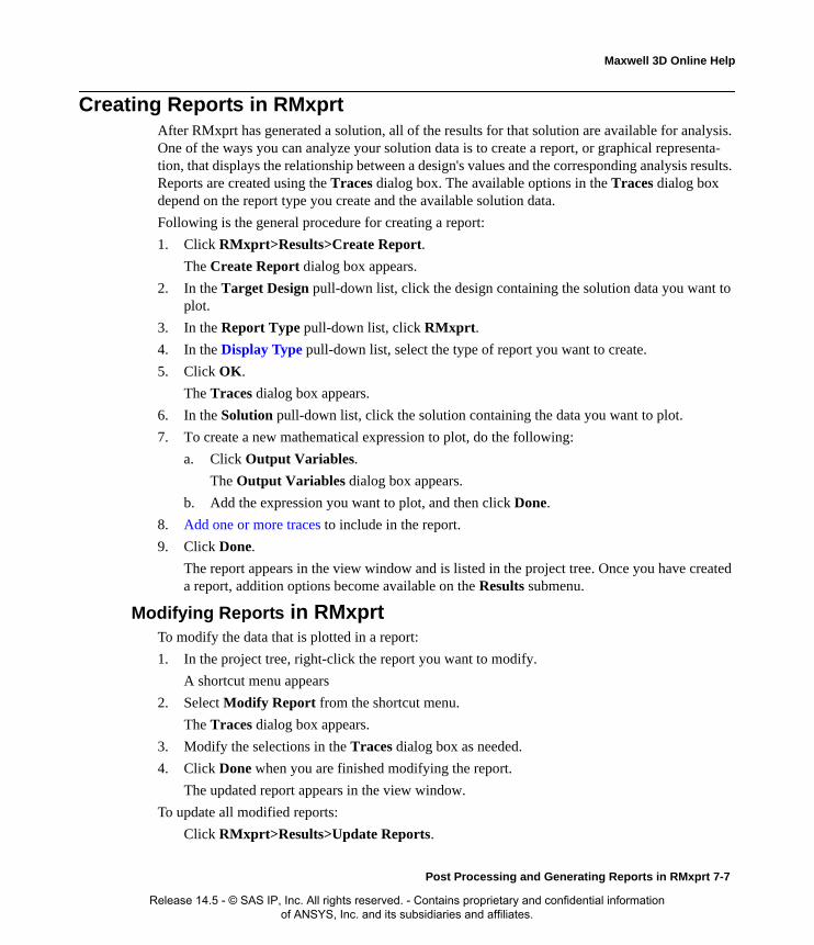
Maxwell 3D Online Help
Creating Reports in RMxprtAfter RMxprt has generated a solution, all of the results for that solution are available for analysis. One of the ways you can analyze your solution data is to create a report, or graphical representa-tion, that displays the relationship between a design's values and the corresponding analysis results. Reports are created using the Traces dialog box. The available options in the Traces dialog box depend on the report type you create and the available solution data.
Following is the general procedure for creating a report:
1. Click RMxprt>Results>Create Report.
The Create Report dialog box appears.
2. In the Target Design pull-down list, click the design containing the solution data you want to plot.
3. In the Report Type pull-down list, click RMxprt.
4. In the Display Type pull-down list, select the type of report you want to create.
5. Click OK.
The Traces dialog box appears.
6. In the Solution pull-down list, click the solution containing the data you want to plot.
7. To create a new mathematical expression to plot, do the following:
a. Click Output Variables.
The Output Variables dialog box appears.
b. Add the expression you want to plot, and then click Done.
8. Add one or more traces to include in the report.
9. Click Done.
The report appears in the view window and is listed in the project tree. Once you have created a report, addition options become available on the Results submenu.
Modifying Reports in RMxprtTo modify the data that is plotted in a report:
1. In the project tree, right-click the report you want to modify.
A shortcut menu appears
2. Select Modify Report from the shortcut menu.
The Traces dialog box appears.
3. Modify the selections in the Traces dialog box as needed.
4. Click Done when you are finished modifying the report.
The updated report appears in the view window.
To update all modified reports:
Click RMxprt>Results>Update Reports.
Post Processing and Generating Reports in RMxprt 7-7
Release 14.5 - © SAS IP, Inc. All rights reserved. - Contains proprietary and confidential information of ANSYS, Inc. and its subsidiaries and affiliates.

Maxwell 3D Online Help
Opening All Reports in RMxprtTo open all reports for a project:
Click RMxprt>Results>Open All Reports.
This opens all reports.
To simplify viewing and comparisons, it may be helpful to use Window>Cascade or Win-dow>Tile Horizontally or Window>Tile Vertically commands.
To close all open reports:
Click Window>Close All.
Deleting All Reports in RMxprtTo delete all reports for a project:
Click RMxprt>Results>Delete All Reports.
This deletes all reports for the project.
Selecting the Display Type in RMxprtThe information in a report can be displayed in several formats. Select from the following Display Type formats in the Create Report dialog box:
Creating 2D Rectangular Plots in RMxprt
A rectangular plot is a 2D, x-y graph of results.
1. Click RMxprt>Results>Create Report.
The Create Report window appears.
2. In the Target Design list, click the design containing the solution data you want to plot.
3. In the Report Type list, click the data type you want to plot.
4. In the Display Type list, click Rectangular Plot.
5. Click OK.
The Traces dialog box appears. The Y tab is selected by default.
6. Under the Y tab, specify the information to plot along the y-axis:
a. In the Category list, click the type of information to plot.
b. In the Quantity list, click the value to plot.
c. In the Function list, click the mathematical function of the quantity to plot.
7. Under the X tab, specify the quantity to plot along the x-axis in one of the following ways:
• Select Use Primary Sweep.
Rectangular Plot A 2D rectangular (x-y) graph.
3D Rectangular Plot A 3D rectangular (x-y-z) graph.
Data Table A spreadsheet with rows and columns that displays, in numeric form, selected quantities against a swept variable or another quantity.
7-8 Post Processing and Generating Reports in RMxprt
Release 14.5 - © SAS IP, Inc. All rights reserved. - Contains proprietary and confidential information of ANSYS, Inc. and its subsidiaries and affiliates.

Maxwell 3D Online Help
The first (primary) sweep variable listed under the Sweeps tab will be plotted along the x-axis.
• Clear the Use Primary Sweep option, and then select the Category, Quantity, and Func-tion of the quantity to plot on the x-axis. The quantity will be plotted against the primary sweep variable listed under the Sweeps tab.
8. Under the Sweeps tab, confirm or modify the sweep variables that will be plotted.
9. Click Add Trace.
A trace represents one or more lines connecting data points on the graph. The trace is added to the traces list at the top of the Traces dialog box. Each column lists an axis on the report and the information that will be plotted on that axis.
10. Optionally, add another trace by following the procedure above.
11. Click Done.
The function of the selected quantity is plotted against the swept variable values or quantities you specified on an x-y graph. The plot is listed under Results in the project tree.
Related Topics
Sweeping a Variable
Working with Traces
Creating 3D Rectangular Plots in RMxprtA rectangular plot is a 3D, x-y-z graph of results.
1. Click RMxprt>Results>Create Report.
The Create Report window appears.
2. In the Target Design list, click the design containing the solution data you want to plot.
3. In the Report Type list, click the data type you want to plot.
4. In the Display Type list, click 3D Rectangular Plot.
5. Click OK.
The Traces dialog box appears. The Z tab is selected by default.
6. Under the Z tab, specify the information to plot along the z-axis:
a. In the Category list, click the type of information to plot.
b. In the Quantity list, click the value to plot.
c. In the Function list, click the mathematical function of the quantity to plot.
7. Under the Y tab, specify the information to plot along the y-axis in one of the following ways:
• Select Use Secondary Sweep.
The second (secondary) sweep variable listed under the Sweeps tab will be plotted along the y-axis.
• Clear the Use Secondary Sweep option, and then select the Category, Quantity, and Function of the quantity to plot on the y-axis. The quantity you select will be plotted against the secondary sweep variable listed under the Sweeps tab.
Post Processing and Generating Reports in RMxprt 7-9
Release 14.5 - © SAS IP, Inc. All rights reserved. - Contains proprietary and confidential information of ANSYS, Inc. and its subsidiaries and affiliates.

Maxwell 3D Online Help
8. Under the X tab, specify the information to plot along the x-axis in one of the following ways:
• Select Use Primary Sweep.
The first (primary) sweep variable listed under the Sweeps tab will be plotted along the x-axis.
• Clear the Use Primary Sweep option, and then select the Category, Quantity, and Func-tion of the quantity to plot on the x-axis. The quantity you select will be plotted against the primary sweep variable listed under the Sweeps tab.
9. Under the Sweeps tab, confirm or modify the swept variables that will be plotted.
10. Click Add Trace.
A trace represents one or more lines connecting data points on the graph. The trace is added to the traces list at the top of the Traces dialog box. Each column lists an axis on the report and the information that will be plotted on that axis.
11. Optionally, add another trace by following the procedure above.
12. Click Done.
The function of the selected quantity or quantities is plotted against the values you specified on an x-y-z graph. The plot is listed under Results in the project tree.
Related Topics
Sweeping a Variable
Working with Traces
Creating Data Tables in RMxprtA data table is a spreadsheet with rows and columns that displays, in numeric form, selected quan-tities against a swept variable or other quantities.
1. Click RMxprt>Results>Create Report.
The Create Report window appears.
2. In the Target Design list, click the design containing the solution data you want to plot.
3. In the Report Type list, click the data type you want to plot.
4. In the Display Type list, click Data Table.
5. Click OK.
The Traces dialog box appears. The Y tab is selected by default.
6. Under the Y tab, select the quantity you are interested in and its associated function:
a. In the Category list, click the type of information to display.
b. In the Quantity list, click the value to display.
c. In the Function list, click the mathematical function to use for the quantity.
7. Under the X tab, select the values you want to plot the quantity against in one of the following ways:
• Select Use Primary Sweep.
7-10 Post Processing and Generating Reports in RMxprt
Release 14.5 - © SAS IP, Inc. All rights reserved. - Contains proprietary and confidential information of ANSYS, Inc. and its subsidiaries and affiliates.
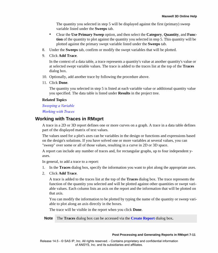
Maxwell 3D Online Help
The quantity you selected in step 5 will be displayed against the first (primary) sweep variable listed under the Sweeps tab.
• Clear the Use Primary Sweep option, and then select the Category, Quantity, and Func-tion of the quantity to plot against the quantity you selected in step 5. This quantity will be plotted against the primary swept variable listed under the Sweeps tab.
8. Under the Sweeps tab, confirm or modify the swept variables that will be plotted.
9. Click Add Trace.
In the context of a data table, a trace represents a quantity's value at another quantity's value or at selected swept variable values. The trace is added to the traces list at the top of the Traces dialog box.
10. Optionally, add another trace by following the procedure above.
11. Click Done.
The quantity you selected in step 5 is listed at each variable value or additional quantity value you specified. The data table is listed under Results in the project tree.
Related Topics
Sweeping a Variable
Working with Traces
Working with Traces in RMxprtA trace in a 2D or 3D report defines one or more curves on a graph. A trace in a data table defines part of the displayed matrix of text values.
The values used for a plot's axes can be variables in the design or functions and expressions based on the design's solutions. If you have solved one or more variables at several values, you can "sweep" over some or all of those values, resulting in a curve in 2D or 3D space.
A report can include any number of traces and, for rectangular graphs, up to four independent y-axes.
In general, to add a trace to a report:
1. In the Traces dialog box, specify the information you want to plot along the appropriate axes.
2. Click Add Trace.
A trace is added to the traces list at the top of the Traces dialog box. The trace represents the function of the quantity you selected and will be plotted against other quantities or swept vari-able values. Each column lists an axis on the report and the information that will be plotted on that axis.
You can modify the information to be plotted by typing the name of the quantity or sweep vari-able to plot along an axis directly in the boxes.
The trace will be visible in the report when you click Done.
Note The Traces dialog box can be accessed via the Create Report dialog box.
Post Processing and Generating Reports in RMxprt 7-11
Release 14.5 - © SAS IP, Inc. All rights reserved. - Contains proprietary and confidential information of ANSYS, Inc. and its subsidiaries and affiliates.

Maxwell 3D Online Help
Removing Traces in RMxprt
You can traces from the traces list in the following ways:
To remove one trace from the report:
• Select the trace you want to remove from the traces list, and then click Remove Trace.
To remove all traces from the report:
• Click Remove All Traces.
Related Topics
Working with Traces
Replacing Traces in RMxprt
To replace a trace in the traces list with a different trace definition:
1. Select the trace you want to remove from the traces list.
2. In the Traces dialog box, specify the information you want to plot along the appropriate axes.
3. Click Replace Trace.
The trace you selected is removed, and the new trace information you specified replaces it in the traces list.
4. Click Done.
Related Topics
Working with Traces
Adding Blank Traces in RMxprt
To add a blank trace to the traces list:
• Click Add Blank Trace.
You can now type the quantities to plot in the appropriate axes boxes.
Related Topics
Working with Traces
Sweeping a Variable in a Report in RMxprtIn RMxprt, a swept variable is an intrinsic, project, or design variable that typically has more than one value. From the Traces dialog box, you can plot any calculated or derived quantity against one or more of the swept variable's values.
When you click the Sweeps tab in the Traces dialog box, the first sweep variable listed is the "pri-mary sweep". If you are creating a 3D report, the second sweep variable listed is the "secondary sweep". Any additional sweep variables are represented as additional curves on the graph.
To modify which variable is the primary sweep variable:
• Click the Name box for the primary sweep variable, and then click the variable name you want to be the primary sweep variable.
7-12 Post Processing and Generating Reports in RMxprt
Release 14.5 - © SAS IP, Inc. All rights reserved. - Contains proprietary and confidential information of ANSYS, Inc. and its subsidiaries and affiliates.
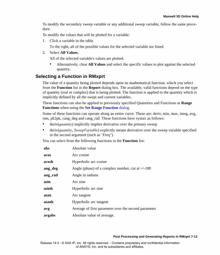
Maxwell 3D Online Help
To modify the secondary sweep variable or any additional sweep variable, follow the same proce-dure.
To modify the values that will be plotted for a variable:
1. Click a variable in the table.
To the right, all of the possible values for the selected variable are listed.
2. Select All Values.
All of the selected variable's values are plotted.
• Alternatively, clear All Values and select the specific values to plot against the selected quantity.
Selecting a Function in RMxprtThe value of a quantity being plotted depends upon its mathematical function, which you select from the Function list in the Report dialog box. The available, valid functions depend on the type of quantity (real or complex) that is being plotted. The function is applied to the quantity which is implicitly defined by all the swept and current variables.
These functions can also be applied to previously specified Quantities and Functions as Range Functions when using the Set Range Function dialog.
Some of these functions can operate along an entire curve. These are: deriv, min, max, integ, avg, rms, pk2pk, cang_deg and cang_rad. These functions have syntax as follows:
• deriv(quantity) implicitly implies derivative over the primary sweep
• deriv(quantity, SweepVariable) explicitly means derivative over the sweep variable specified in the second argument (such as "Freq").
You can select from the following functions in the Function list:
abs Absolute value
acos Arc cosine
acosh Hyperbolic arc cosine
ang_deg Angle (phase) of a complex number, cut at +/-180
ang_rad Angle in radians
asin Arc sine
asinh Hyperbolic arc sine
atan Arc tangent
atanh Hyperbolic arc tangent
avg Average of first parameter over the second parameter
avgabs Absolute value of average.
Post Processing and Generating Reports in RMxprt 7-13
Release 14.5 - © SAS IP, Inc. All rights reserved. - Contains proprietary and confidential information of ANSYS, Inc. and its subsidiaries and affiliates.

Maxwell 3D Online Help
cang_deg Cumulative angle (phase) of the first parameter (a complex number) in degrees, along the second parameter (typically sweep variable). Returns a double precision value cut at +/-180.
cang_rad Cumulative angle of the first parameter in radians along a second parameter (typically a sweep variable) Returns a double precision value.
conjg Conjugate of the complex number.
cos Cosine
cosh Hyperbolic cosine
crestfactor Peak/RMS (root mean square) for the selected simulation quantity
dB(x) 20*log10(|x|)
dBm(x) 10*log10(|x|) +30
dBW(x) 10*log10(|x|)
deriv Derivative of first parameter over second parameter.
even Returns 1 if integer part of the number is even; returns 0 otherwise
exp Exponential function (the natural anti-logarithm)
formfactor Returns root mean square RMS/Mean Absolute Value for the selected simulation quantity.
iae Returns the integral of the absolute deviation of the selected quantity from a target value that is entered via the additional argument. To use this function, you need to open the Add Trace Characteristics dialog and select the Error category.
im Imaginary part of the complex number
int Truncated integer function
integ Integral of the selected quantity. Uses trapezoidal area..
integabs Absolute value of integral.
ise Returns the integral of the squared deviation of the selected quantity from a target value that is entered via an additional argument. To use this function, you need to open the Add Trace Characteristics dialog and select the Error category.
itae Returns the time-weighted absolute deviation of the selected quantity from a target value that is entered via an additional argument.To use this function, you need to open the Add Trace Characteristics dialog and select the Error category.
7-14 Post Processing and Generating Reports in RMxprt
Release 14.5 - © SAS IP, Inc. All rights reserved. - Contains proprietary and confidential information of ANSYS, Inc. and its subsidiaries and affiliates.
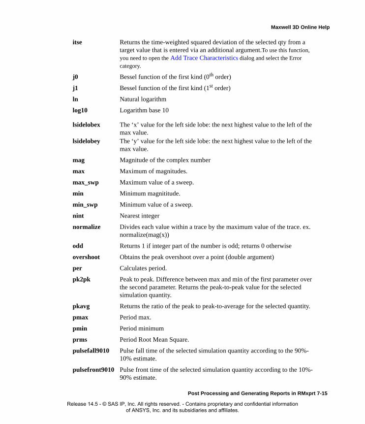
Maxwell 3D Online Help
itse Returns the time-weighted squared deviation of the selected qty from a target value that is entered via an additional argument.To use this function, you need to open the Add Trace Characteristics dialog and select the Error category.
j0 Bessel function of the first kind (0th order)
j1 Bessel function of the first kind (1st order)
ln Natural logarithm
log10 Logarithm base 10
lsidelobex The ‘x’ value for the left side lobe: the next highest value to the left of the max value.
lsidelobey The ‘y’ value for the left side lobe: the next highest value to the left of the max value.
mag Magnitude of the complex number
max Maximum of magnitudes.
max_swp Maximum value of a sweep.
min Minimum magnititude.
min_swp Minimum value of a sweep.
nint Nearest integer
normalize Divides each value within a trace by the maximum value of the trace. ex. normalize(mag(x))
odd Returns 1 if integer part of the number is odd; returns 0 otherwise
overshoot Obtains the peak overshoot over a point (double argument)
per Calculates period.
pk2pk Peak to peak. Difference between max and min of the first parameter over the second parameter. Returns the peak-to-peak value for the selected simulation quantity.
pkavg Returns the ratio of the peak to peak-to-average for the selected quantity.
pmax Period max.
pmin Period minimum
prms Period Root Mean Square.
pulsefall9010 Pulse fall time of the selected simulation quantity according to the 90%-10% estimate.
pulsefront9010 Pulse front time of the selected simulation quantity according to the 10%-90% estimate.
Post Processing and Generating Reports in RMxprt 7-15
Release 14.5 - © SAS IP, Inc. All rights reserved. - Contains proprietary and confidential information of ANSYS, Inc. and its subsidiaries and affiliates.

Maxwell 3D Online Help
pulsefront3090 Pulse front time of the selected simulation quantity according to the 30%-90% estimate.
pulsemax Pulse maximum from the front and tail estimates for the selected simulation quantity.
pulsemaxtime Time at which the maximum pulse value of the selected simulation quantity is reached.
pulsemin Pulse minimum from the front and tail estimates for the selected simulation quantity.
pulsemintime Tiime at which the minimum pulse value of the selected simulation quantity is reached.
pulsetail50 Pulse tail time of the selected simulation quantity from the virtual peak to 50%.
pulsewidth5050 Pulse width of the selected simulation quantity as measured from the 50% points on the pulse front and pulse tail.
PulseWidth Functions
pw_plus Pulse width of first positive pulse
pw_plus_max Max. Pulse width of input stream
pw_plus_min Min. Pulse width of input stream
pw_plus_avg Average of the positive pulse width input stream
pw_plus_rms RMS of the positive pulse width input stream
pw_minus_max Max. Pulse width of input stream
pw_minus_min Min. Pulse width of input stream
pw_minus_avg Average of the negative pulse width input stream
pw_minus_rms RMS of the negative pulse width input stream
polar Converts the complex number in rectangular to polar
re Real part of the complex number
rect Converts the complex number in polar to rectangular
rem Fractional part
ripple Returns the ripple factor (AC RMS/Mean) for the selected quantity.
rms Returns total root mean square of the selected quantity.
rmsAC Returns the AC RMS for the selected quantity.
7-16 Post Processing and Generating Reports in RMxprt
Release 14.5 - © SAS IP, Inc. All rights reserved. - Contains proprietary and confidential information of ANSYS, Inc. and its subsidiaries and affiliates.

Maxwell 3D Online Help
Selecting a Parameter, Variable, or Quantity to Plot in RMxprtEach trace in a report includes a quantity that is plotted along an axis. The quantity being plotted can be a value that was calculated by RMxprt, such as L11, a value from a calculated expression.
rsidelobex The ‘x’ value for the right side lobe: the next highest value to the right of the max value.
rsidelobey The ‘y’ value for the right side lobe: the next highest value to the right of the max value.
sgn Sign extraction
sin Sine
sinh Hyperbolic sine
sqrt Square root
tan Tangent
tanh Hyperbolic tangent
Undershoot Obtains the peak undershoot over a point (double argument).
XAtYMax Threshold crossing time: report first time (x value) at which an output quantity crosses YMax.
XAtYMin Threshold crossing time: report first time (x value) at which an output quantity crosses a user definable threshold (YMin).
XAtYVal Returns the X value at the first occurance of Y value.
xdb10beamdwidth
Width between left and right occurrences of values ‘x’ db10 from max. Takes 'x' as argument (3.0 default). To use this function, you need to open the Add Trace Characteristics dialog and select the Radiation category.
xdb20beamwidth
Width between left and right occurrences of values ‘x’ db20 from max. Takes 'x' as argument (3.0 default) To use this function, you need to open the Add Trace Characteristics dialog and select the Radiation category.
y0 Bessel function of the second kind (0th order)
y1 Bessel function of the second kind (1st order)
YAtXMax Threshold crossing time: report first time (y value) at which an output quantity crosses XMax.
YAtXMin Threshold crossing time: report first time (y value) at which an output quantity crosses a user definable threshold (XMin).
YatXVal Returns the Y value at the first occurance of X value.
Post Processing and Generating Reports in RMxprt 7-17
Release 14.5 - © SAS IP, Inc. All rights reserved. - Contains proprietary and confidential information of ANSYS, Inc. and its subsidiaries and affiliates.

Maxwell 3D Online Help
To select a parameter, variable, or quantity to plot:
1. In the Traces dialog box, select one of the following categories:
2. Select a quantity to plot from the Quantity list. The available quantities depend on the selected category and the setup of the design.
Variables User-defined project or design variables.
Output Variables Derived quantities RMxprt project or design variables, parameters or solution curves.
7-18 Post Processing and Generating Reports in RMxprt
Release 14.5 - © SAS IP, Inc. All rights reserved. - Contains proprietary and confidential information of ANSYS, Inc. and its subsidiaries and affiliates.

Maxwell 3D Online Help
Creating Quick Reports in RMxprtFollowing is the procedure for creating a quick report.
1. On the Project tree, select a setup or sweep icon of interest.
2. Right-click to display the shortcut menu and select Quick Report.
The Quick Report dialog appears.
3. Select the one or more categories for the report from the list and click OK.
A rectangular plot for each selected category displays. The new plot or plots appear in the Project tree under the Results icon.
Related Topics
Creating Reports
Modifying Reports
RMxprt Quick Report Categories
RMxprt Quick Report CategoriesWhen using the Quick Reports function for Solutions, the following report categories may be available depending upon the solution parameters requested, solution type, etc:
Category Description
Coil Voltage Report voltages in the machine coil.
Current Report currents for each line or phase of the machine, source current, line current, armature current.
Flux Density Report flux density in the machine air gap, flux linkages.
Induced Voltage
Report Induced Line and Phase voltages.
Misc. Report miscellaneous quantities specific to the machine type such as power factor, torque to current ratio.
Percentage Report machine efficiency.
Power Report air gap power, output power.
Torque Report cogging torque, output torque, magnet generated torque, induction torque.
Voltage Report Line and Phase voltage.
Post Processing and Generating Reports in RMxprt 7-19
Release 14.5 - © SAS IP, Inc. All rights reserved. - Contains proprietary and confidential information of ANSYS, Inc. and its subsidiaries and affiliates.

Maxwell 3D Online Help
Angle Reports power factor angle.
Angular Speed Reports angular speed.
Inductance Reports air gap permeance.
7-20 Post Processing and Generating Reports in RMxprt
Release 14.5 - © SAS IP, Inc. All rights reserved. - Contains proprietary and confidential information of ANSYS, Inc. and its subsidiaries and affiliates.

8
Specifying RMxprt Winding Data
To define the winding data for an RMxprt machine
1. In the project tree, under Machine, open the folder that requires a winding, and double-click Winding to open the winding Properties dialog box.
• For some machine types this would be Machine>Rotor>Winding, for others, Machine>Stator>Winding.
• You can also enter values in the Properties section of the desktop without opening a sep-arate window.
2. Specify the desired settings.
3. Click OK to close the Properties dialog box.
The specific properties available depend on the specific machine.
The following machine types have winding data available:
• Three-Phase Induction Motors (stator winding) and (rotor winding)
• Three-Phase Synchronous Machines (stator winding) and (rotor winding)
• Brushless PMDC Motors (stator winding)
• Adjust-Speed Synchronous Machines (stator winding)
• PMDC Motors (rotor winding)
• Switched Reluctance Motors (stator winding)
• Line-Start Permanent-Magnet Synchronous Motors (stator winding)
• Universal Motors (stator winding) and (rotor winding)
• General DC Machines (rotor winding)
• Claw-Pole Alternators (stator winding)
• Generic Rotating Machines
Specifying RMxprt Winding Data 8-1
Release 14.5 - © SAS IP, Inc. All rights reserved. - Contains proprietary and confidential information of ANSYS, Inc. and its subsidiaries and affiliates.

Maxwell 3D Online Help
Setting the Winding TypeRMxprt can automatically arrange almost all commonly used single- or double-layer poly-phase ac windings provided all coils have the same number of turns. Users do not need to define coils one by one. For a double-layer winding, RMxprt can also handle the coils with half turns which are arranged in the order of even, odd, even, odd, …, as long as it is physically possible.
RMxprt also provides a very flexible tool Winding Editor in order for the users to design a vari-ety of special winding types according to their own needs, such as compound single- and double-layer winding, big- and small-phase-spread variable-pole multiple-speed winding, sine-wave three-phase winding, and so forth. The Winding Editor is available to the following types of electric machines:
1. Three-phase induction motors
2. Single-phase induction motors
3. Three-phase synchronous motors and generators
4. Line-start permanent-magnet synchronous motors
5. Claw-pole alternators
6. Adjustable-speed permanent-magnet synchronous motors and generators
7. Brushless permanent-magnet DC motors
When you edit the AC winding of a new design for the first time, RMxprt creates a default winding arrangement based on the basic winding specifications: Number of Phases, Number of Poles, Number of Slots, Winding Layers, Conductors per Slot, and Coil Pitch. Then you can edit the winding configuration based on the default arrangement.
Winding Types Available for MachinesUse the Winding Type dialog to set the Winding type.
1. To display the Winding Type dialog double-click on the Winding property button.
Passing the cursor over the buttons for the Winding types changes the graphic to show the available windings for the motor in the design. Choices differ depending on the motor. A Winding Editor selection does not have a graphic.
Selections for the Three Phase Induction Motor (stator winding) and (rotor winding), Three-Phase Synchronous Machine (stator winding) and (rotor winding), Brushless Permanent Mag-net DC Motor (stator winding), Adjust Speed Synchronous Machine (stator winding), Line Start PM Synchronous Motor (stator winding), and Claw Pole alternator (stator winding) include:
• Editor - enable the Winding Editor
• Whole Coiled
• Half Coiled
Selections for the DC Permanent Magnet Motor (rotor winding) and Universal Motor include (stator winding) and (rotor winding):
• Lap
8-2 Specifying RMxprt Winding Data
Release 14.5 - © SAS IP, Inc. All rights reserved. - Contains proprietary and confidential information of ANSYS, Inc. and its subsidiaries and affiliates.

Maxwell 3D Online Help
• Wave
Selection for the General DC Machines (rotor winding) include:
• Lap
• Wave
• Frogleg
Selections for single-phase induction motor include:
• Editor - enable the Winding Editor
• Lap - 90 deg phase belt 2-layer coil for both single and double layer
• Sin_1 - first class sinusoidal coil four double layer only
• Sin_2 - second class sinusoidal coil four double layer only
The Switched Reluctance motor does not involve winding selections.
2. Select the Winding Type and click OK.
This closes the window and sets the Winding Type property. If you select the Editor type, It also enables the Machine>Edit Layout command on the menu bar.
Enable the Winding Editor
Setting the Winding Type property to Editor enables the command Machine>Edit Layout on the menu bar. To display the dialog box Winding Editor:
1. Open the Winding Properties window and set the Winding Type value to Editor. To do this, double-click on the button Winding Type value to display the Winding Type selection win-dow.
2. Select Editor as the Winding Type and click OK. This closes the Winding Type selection win-dow and sets the Winding Type Value to Editor. It also enables the command Machine>Wind-ing>Edit Layout on the menu bar. Now the Machine Editor window displays the default
Specifying RMxprt Winding Data 8-3
Release 14.5 - © SAS IP, Inc. All rights reserved. - Contains proprietary and confidential information of ANSYS, Inc. and its subsidiaries and affiliates.

Maxwell 3D Online Help
winding arrangement.
3. Click Machine>Winding>Edit Layout. This displays the dialog box Winding Editor as shown. The dialog box Winding Editor includes functions that do not appear in the tab sheet Winding Editor in the RMxprt Machine Editor window.
8-4 Specifying RMxprt Winding Data
Release 14.5 - © SAS IP, Inc. All rights reserved. - Contains proprietary and confidential information of ANSYS, Inc. and its subsidiaries and affiliates.

Maxwell 3D Online Help
4.
Edit Winding Configuration
Each row of the winding data table in the dialog box Winding Editor in Figure 3.13 is identified with the coil index in the column Coil. This information is displayed in the tab sheet Winding Edi-tor in the RMxprt Machine Editor window as well, but it is editable in the dialog box Winding Edi-tor.
The winding data table contains four columns:
Setting the Number of Winding LayersTo set the number of winding layers:
1. Open the Winding Properties window by double-clicking on the Winding icon in the proper-ties window.
2. Use the drop-down menu in the Winding Layers field to set the number as 1 or 2.
This sets the winding layers used in the winding.
The number of layers selected makes a difference in the display of data in the Winding Edi-tor.
Connecting and Disconnecting Windings
When you have specified the winding data, you can execute the following commands to automati-cally connect or disconnect the windings.
• Machine>Winding>Connect All Coils
Upon executing, the graphical display in the main window shows the connections.
• Machine>Winding>Disconnect All Coils
Upon executing, the graphical display in the main window updates to remove the connection.
Related Topics
View Winding Connections
Phase is for the phase to which the coil belongs.
Turns is for the number of turns of the coil.
In Slotsis for the slot number with the coil side current flowing in ('flow-in-side' for short). If 2 Layers are specified in the Winding Properties
window, the slot number ends with a "T" to show the top layer.
Out Slotsis for the slot number with the coil side current flowing out ("flow-out-
side" for short). If 2 Layers are specified in the Winding Properties window, the slot number ends with a "B" to show the bottom layer.
Specifying RMxprt Winding Data 8-5
Release 14.5 - © SAS IP, Inc. All rights reserved. - Contains proprietary and confidential information of ANSYS, Inc. and its subsidiaries and affiliates.
Maxwell 3D Online Help
Poly-phase Winding EditorRMxprt provides a Winding Editor in order for users to design variety of special winding types according to their own needs, such as compound single- and double-layer winding, big- and small-phase-spread variable-pole multiple-speed winding, sine-wave three-phase winding, and so forth. The Winding Editor is available to the following types of electric machines:
• Three-phase Induction Motor
• Three-phase Synchronous Motor
• Three-phase Synchronous Generator
• Permanent-magnet Synchronous Generator
• Line-start Permanent-magnet Synchronous Motor
• Adjustable-speed Permanent-magnet Synchronous Motor
• Brushless Permanent-magnet DC Motor
• Claw-pole Alternator
You input data for Number of Poles in the Machine Properties window and data for the Number of Slots and Slot Type in the Stator Properties window. You set the Number of Slots in the Winding Properties window. RMxprt automatically arranges the winding layout and display the relevant information that has been specified in the Winding Editor tab of the RMxprt main win-dow. As long as the edited winding data have been saved, the Winding Editor tab will display the last saved winding data whenever Winding Editor dialog is launched. The left top part of the Winding Editor tab shows the winding data, as does the Winding Editor dialog. In this area, the total number of rows equals half the number of slots.
Enabling the Winding Editor Dialog
Setting the Winding Type property to Editor enables the Machine>Edit Layout command on the menu bar. To display the Winding Editor dialog:
1. Open the Winding Properties window and set the Winding property to Editor.
To do this, double-click on the Winding property button to display the Winding Type selec-tion window.
2. Select Editor as the Winding Type and click OK.
This closes the Winding Type window and sets the Winding Type property to Editor. It also enables the Machine>Edit Layout command on the menu bar.
3. Click Machine>Edit Layout.
This displays the Winding Editor dialog. The Winding Editor dialog box includes functions that do not appear in the RMxprt main window Winding Editor tab.
You can also invoke the Winding Editor dialog by:
a. Right-click on the data table section of the Winding Editor tab of the main window.
b. This displays an Edit Layout button.
c. Click the Edit Layout button to display the Winding Editor dialog.
8-6 Specifying RMxprt Winding Data
Release 14.5 - © SAS IP, Inc. All rights reserved. - Contains proprietary and confidential information of ANSYS, Inc. and its subsidiaries and affiliates.

Maxwell 3D Online Help
You can also display the Winding Editor dialog by:
a. Right click in the Winding Editor tab main window display.
This displays a shortcut menu.
b. Click Edit Layout from the shortcut menu.
Each row of the winding data is identified with coil index in the Coil column. This information is displayed in the Winding Editor tab in the RMxprt Main window, and it editable in the Winding Editor dialog.
• Column Phase is for the phase to which the coil belongs.
• Column Turns is for the number of turns of coil.
• Column In Slots is for the slot number with the coil side current flowing in ('flow-in-side' for short). If 2 Layers are specified in the Winding Properties window, the slot number ends with a "T" to show the top layer.
• Column Out Slots is for the slot number with the coil side current flowing out ('flow-out-side' for short). If 2 Layers are specified in the Winding Properties window, the slot number ends with a "B" to show the bottom layer.
By changing the belonging phase in column Phase, the number of turns in column Turns, the flow-in-side slot number in column In Slot, the flow-out-side slot number in column Out Slot for each coil, it is possible to arrange the distribution of coils of single and double layer winding of any type required.
The Winding Editor dialog also includes three check boxes:
• Periodic Multiplier: indicates the possibility to select the number of unit machines for editing winding arrangement. It has a drop-down menu to show the possible numbers for the periodic multiplier.
When checked, the pull-down list box to the right displays the numbers of unit machines for selection. Selecting 1 means whole slots are considered as one unit machine, and all coils is listed in the table of the edit window. Selecting 2 lists half of the total coils in the table, and whole slots are divided into two unit machines, etc. When the check box Periodic Multiplier: is unchecked, the pull-down list box to the right is grayed (enabled); all the coils are listed in the table.
• Constant Turns.
Checking the check box (multiple choices) Constant Turns indicates that the number of turns keeps constant and the column Turns in the table is grayed (disabled). If the check box Con-stant Turns is unchecked, the column Turns in the table is brightened allowing for editing and modifying the number of turns.
• Constant Pitch
Checking this box grays the Out Slots column to the values cannot be edited. It means that the coil pitch is constant. For two-layer windings, all flow-in-side slots are defined as top layer, and all flow-out-side slots as bottom layer. The flow-out-side slot number is automatically computed based on the input in the edit box Coil Pitch in Stator2 page in RMxprt window, and Out Slot column is disabled.
Specifying RMxprt Winding Data 8-7
Release 14.5 - © SAS IP, Inc. All rights reserved. - Contains proprietary and confidential information of ANSYS, Inc. and its subsidiaries and affiliates.

Maxwell 3D Online Help
When the check box Constant Pitch is unchecked, the column Out Slot is enabled to allow arbitrarily changing slot pitch for each coil.
The Winding Editor dialog includes three command buttons.
• Click the command button Default in the window Winding Editor, all the data in the table resumes to the situation of data from automatic arrangement by RMxprt.
• Click the command button Reset in the window Winding Editor, all the data in the table resumes to the situation of data when the window Winding Editor was first opened, or resumes to the data that you have saved.
• Click OK to accept the current values and close the Winding Editor dialog.
Windings Basic Terminology
Conductor
A conductor refers to a half turn of a coil. A conductor may be formed with one insulated wire, or with several strands of insulated wires.
Strands
A conductor may consist of several wires of same or different sizes stranded together. The number of strands is also called number of wires per conductor. The conductor current may not uniformly distribute among all wires, but the current density is uniformly distributed.
Coil
A coil is wound with several turns, each turn consisting of two conductors. Coils are generally wound with insulation-wrapped electromagnetic wire continuously on a winding mould. However, coils with single-turn for heavy current are often formed with two separate thick conductors. A thick conductor is hammered onto the winding mould to form a half-coil. The linear part of a con-ductor imbedded into a slot of iron core is termed effective side.
Coil Pitch
The number of slots of the armature iron core spanned by the two effective sides of a coil is termed coil pitch, denoted by y. For instance, if the side of a coil in the 1-st slot spans 8 slots and is con-nected to the side of the coil in the 9-th slot, the coil pitch of the coil is y = 8.
Coil Set
The coils belonging to the same phase under one pole are connected in series as a coil set.
Full coil pitch: coil pitch = pole pitch
Short coil pitch: coil pitch < pole pitch
Long coil pitch: coil pitch > pole pitch, usually used in variable-pole multiple-speed machines
Pole pitch: distance between two contiguous poles measured in number of slots.
polepitch totalnumberofslotsnumberofpoles
---------------------------------------------------=
8-8 Specifying RMxprt Winding Data
Release 14.5 - © SAS IP, Inc. All rights reserved. - Contains proprietary and confidential information of ANSYS, Inc. and its subsidiaries and affiliates.

Maxwell 3D Online Help
Winding
The coils or coil sets of a phase are connected according to certain rules to form a phase winding. A phase may consist of several branches connected in parallel. Every branch must produce exactly the same back emf and must have the same resistance. As a result, the phase winding current is uni-formly distributed among all branches.
In summary, a winding may be connected with several branches in parallel; each branch consists of one or more coil sets connected in series; a coil set may have several series coils; a coil is wound with a number of turns; a turn is formed by two conductors; a conductor may be stranded by one or more same- or different-size wires.
Poly Phase AC Winding
The common armature winding of poly-phase ac machines is catalogued and classified as shown in
the following table.
Polyphase AC Winding
Double layer Variable-pole multiple speed type
Fractional slot number type
Wave-type
Concentric type
Lap Type
Single Layer Crossed Concentric type (whole coiled or half coiled)
Crossed Chain-type (whole coiled or half coiled)
Concentric type (whole coiled or half coiled)
Lap-type (whole coiled or half coiled)
Chain-type (whole coiled or half coiled)
Compound layer
Specifying RMxprt Winding Data 8-9
Release 14.5 - © SAS IP, Inc. All rights reserved. - Contains proprietary and confidential information of ANSYS, Inc. and its subsidiaries and affiliates.
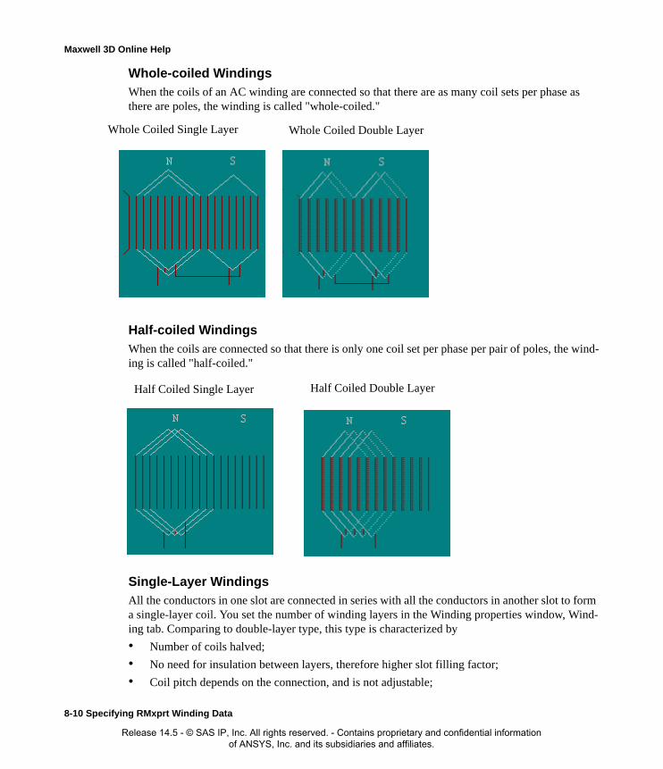
Maxwell 3D Online Help
Whole-coiled Windings
When the coils of an AC winding are connected so that there are as many coil sets per phase as there are poles, the winding is called "whole-coiled."
Half-coiled Windings
When the coils are connected so that there is only one coil set per phase per pair of poles, the wind-ing is called "half-coiled."
Single-Layer WindingsAll the conductors in one slot are connected in series with all the conductors in another slot to form a single-layer coil. You set the number of winding layers in the Winding properties window, Wind-ing tab. Comparing to double-layer type, this type is characterized by
• Number of coils halved;
• No need for insulation between layers, therefore higher slot filling factor;
• Coil pitch depends on the connection, and is not adjustable;
Whole Coiled Single Layer Whole Coiled Double Layer
Half Coiled Single Layer Half Coiled Double Layer
8-10 Specifying RMxprt Winding Data
Release 14.5 - © SAS IP, Inc. All rights reserved. - Contains proprietary and confidential information of ANSYS, Inc. and its subsidiaries and affiliates.

Maxwell 3D Online Help
• Being widely used in small capacity electric machines.
According to different layouts of the end winding, single-layer windings are classified as chain-, lap-, concentric- and crossed-types.
Chain-type Windings
The name single-layer chain-type is from the linked chain-like developed winding diagram. For a chain-type winding, every coil set has only one coil.
Half-coiled Chain-type Winding
An example of three-phase 6-pole 18-slot single-layer half-coiled chain-type winding is shown in the following figure.
Specifying RMxprt Winding Data 8-11
Release 14.5 - © SAS IP, Inc. All rights reserved. - Contains proprietary and confidential information of ANSYS, Inc. and its subsidiaries and affiliates.

Maxwell 3D Online Help
Whole-coiled Chain-type Winding
An example of three-phase 4-pole 24-slot single-layer whole-coiled chain-type winding is shown in the following figure.
Lap-type Windings
The name single-layer lap-type is from the lapped layout of end connection. In a lap-type winding, at least one coil set has 2 or more coils which are overlapped each other. If some coil sets have only one coil, this winding type is also called "crossed lap-type".
8-12 Specifying RMxprt Winding Data
Release 14.5 - © SAS IP, Inc. All rights reserved. - Contains proprietary and confidential information of ANSYS, Inc. and its subsidiaries and affiliates.
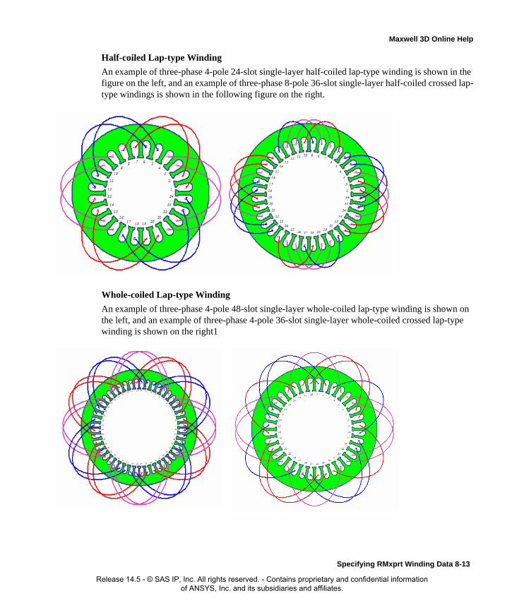
Maxwell 3D Online Help
Half-coiled Lap-type Winding
An example of three-phase 4-pole 24-slot single-layer half-coiled lap-type winding is shown in the figure on the left, and an example of three-phase 8-pole 36-slot single-layer half-coiled crossed lap-type windings is shown in the following figure on the right.
Whole-coiled Lap-type Winding
An example of three-phase 4-pole 48-slot single-layer whole-coiled lap-type winding is shown on the left, and an example of three-phase 4-pole 36-slot single-layer whole-coiled crossed lap-type winding is shown on the right1
Specifying RMxprt Winding Data 8-13
Release 14.5 - © SAS IP, Inc. All rights reserved. - Contains proprietary and confidential information of ANSYS, Inc. and its subsidiaries and affiliates.
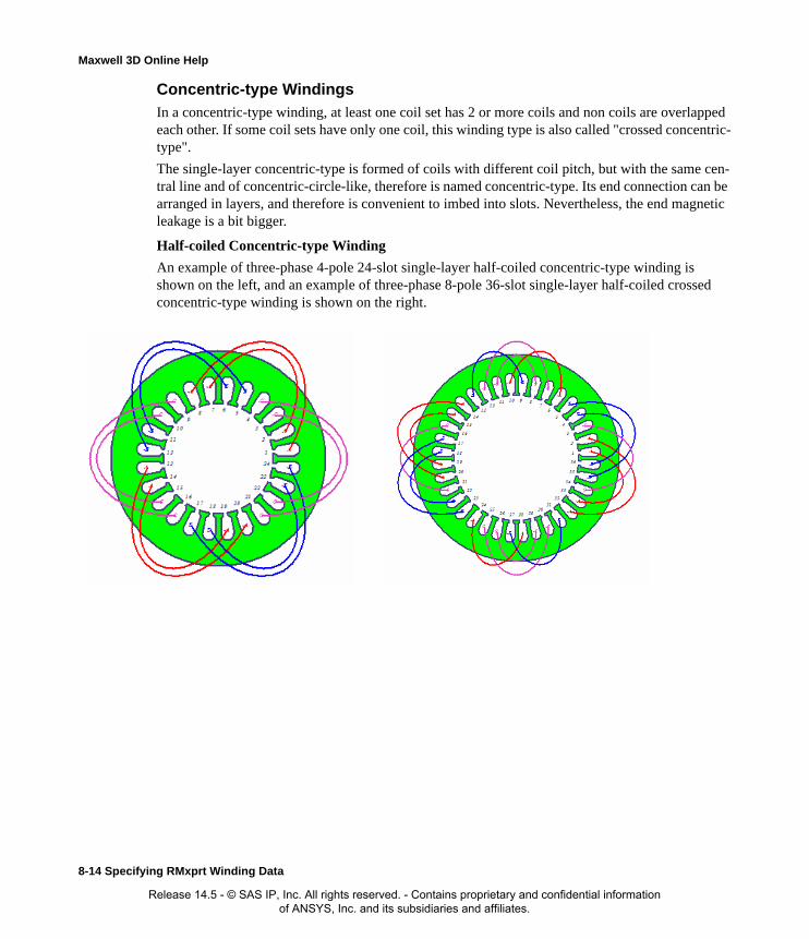
Maxwell 3D Online Help
Concentric-type Windings
In a concentric-type winding, at least one coil set has 2 or more coils and non coils are overlapped each other. If some coil sets have only one coil, this winding type is also called "crossed concentric-type".
The single-layer concentric-type is formed of coils with different coil pitch, but with the same cen-tral line and of concentric-circle-like, therefore is named concentric-type. Its end connection can be arranged in layers, and therefore is convenient to imbed into slots. Nevertheless, the end magnetic leakage is a bit bigger.
Half-coiled Concentric-type Winding
An example of three-phase 4-pole 24-slot single-layer half-coiled concentric-type winding is shown on the left, and an example of three-phase 8-pole 36-slot single-layer half-coiled crossed concentric-type winding is shown on the right.
8-14 Specifying RMxprt Winding Data
Release 14.5 - © SAS IP, Inc. All rights reserved. - Contains proprietary and confidential information of ANSYS, Inc. and its subsidiaries and affiliates.
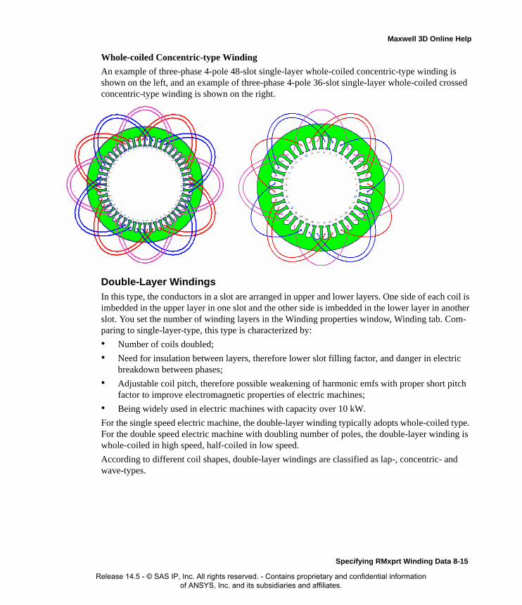
Maxwell 3D Online Help
Whole-coiled Concentric-type Winding
An example of three-phase 4-pole 48-slot single-layer whole-coiled concentric-type winding is shown on the left, and an example of three-phase 4-pole 36-slot single-layer whole-coiled crossed concentric-type winding is shown on the right.
Double-Layer Windings
In this type, the conductors in a slot are arranged in upper and lower layers. One side of each coil is imbedded in the upper layer in one slot and the other side is imbedded in the lower layer in another slot. You set the number of winding layers in the Winding properties window, Winding tab. Com-paring to single-layer-type, this type is characterized by:
• Number of coils doubled;
• Need for insulation between layers, therefore lower slot filling factor, and danger in electric breakdown between phases;
• Adjustable coil pitch, therefore possible weakening of harmonic emfs with proper short pitch factor to improve electromagnetic properties of electric machines;
• Being widely used in electric machines with capacity over 10 kW.
For the single speed electric machine, the double-layer winding typically adopts whole-coiled type. For the double speed electric machine with doubling number of poles, the double-layer winding is whole-coiled in high speed, half-coiled in low speed.
According to different coil shapes, double-layer windings are classified as lap-, concentric- and wave-types.
Specifying RMxprt Winding Data 8-15
Release 14.5 - © SAS IP, Inc. All rights reserved. - Contains proprietary and confidential information of ANSYS, Inc. and its subsidiaries and affiliates.

Maxwell 3D Online Help
Double-layer Lap-type Winding
An example of three-phase 4-pole 24-slot whole-coiled double-layer lap-type windings (short pitch y = 5) is shown below.
Double-layer Concentric-type Winding
An example of three-phase 4-pole 24-slot whole-coiled double-layer concentric-type windings (short pitch y = 5) is shown below.
8-16 Specifying RMxprt Winding Data
Release 14.5 - © SAS IP, Inc. All rights reserved. - Contains proprietary and confidential information of ANSYS, Inc. and its subsidiaries and affiliates.

Maxwell 3D Online Help
Double-layer Wave-type Winding
The name double-layer wave-type is from the wave-like developed winding diagram as shown below.
Compared to lap-type:
• The winding of each phase connects the coils under different poles in series in one round, and returns to the left to the first coil, then winds the next round, and so on so forth until all the coils belonging to this phase are connected.
• This type is usually used in single-turn preformed hard coil for low voltage high current elec-tric machines.
• This type needs less connection wire between poles.
Fractional-Pitch Winding
First, introduce a number q, called number of slots per pole per phase, which is defined as
A fractional-pitch winding has a fractional number .
An example of three-phase 6-pole 45-slot fractional-pitch double-layer winding
phasesofnumberpolesofnumber
slotsofnumbertotalq
×=
d
cbq =
Specifying RMxprt Winding Data 8-17
Release 14.5 - © SAS IP, Inc. All rights reserved. - Contains proprietary and confidential information of ANSYS, Inc. and its subsidiaries and affiliates.

Maxwell 3D Online Help1 1
( , short pitch y = 7, pole pitch ) is shown here.
Auto-arrangement of AC Windings
RMxprt can arrange these windings automatically if all coils have the same number of turns. This section describes the process to automatically arrange the coil distribution.For winding layout dis-play in RMxprt, the lap-type is default if windings are automatically arranged. If a concentric-type layout display is desired, the winding can be defined by winding editor, as described in the next section.
The wave-type winding is effective to a lap-type winding, and is also displayed as a lap-type wind-ing.
Star Vector Diagram
The conductors (or coils) in slots produce emf (or mmf), which can be expressed with unit vector. When the electric machine has number of pole p, and number of slots Z, the angular phase differ-ence in electric degrees between two contiguous slots is
22q =
27=τ
Z
180p °×=α
8-18 Specifying RMxprt Winding Data
Release 14.5 - © SAS IP, Inc. All rights reserved. - Contains proprietary and confidential information of ANSYS, Inc. and its subsidiaries and affiliates.

Maxwell 3D Online Help
Drawing the vectors of emfs (or mmfs) in all the slots according to their phase angles forms the star vector diagram of the winding. The figure below shows an example of the star vector diagram of 4-pole 24-slot winding.
If there exists the greatest common factor t between the number of slots Z and the number of pole pairs pp (= p/2), the star vector diagram repeats t times, i.e. the winding has t periods. Let
,
and
,
then Z0 and p0 construct a complete star vector diagram and form a unit electric machine. For the whole-pitch winding electric machine (q, as shown later, is an integer), t = p/2. For the fractional-pitch winding electric machine,
where m is the number of phases. If t > 1, the angular phase difference between two contiguous vectors is
and the difference between the ordinal numbers of the slots of two contiguous vectors is
where G is a minimum integer to make y0 equal to an integer (y0 should take into account the possi-ble reverse connection of coils under the contiguous pole).
t
ZZ0 =
t
pp0 =
d
cb
mp
Zq +==
0Z
360 °=α
d
1Gcbdmy0
−+= )(
Specifying RMxprt Winding Data 8-19
Release 14.5 - © SAS IP, Inc. All rights reserved. - Contains proprietary and confidential information of ANSYS, Inc. and its subsidiaries and affiliates.

Maxwell 3D Online Help
Phase Spread
In the star vector diagram of a unit electric machine, the range occupied by the vectors of each phase under one pole is termed phase spread, expressed in electric degrees or number of slots. For a single-layer winding, the phase spread is 180°/m (m – the number of phases). The phase spread of a double-layer half-coiled winding is 360°/m, and the phase spread of a double-layer full-coiled winding is 180°/m.
The phase spread of a 2-phase winding is always 90° (= 180°/m). Therefore, a 2-phase winding cannot take the double-layer half-coiled winding type. The windings for single-phase induction motor are also considered as 2-phase windings.
When the number of phases is an even number of greater than or equal to 4, the phase spread is always 360°/m. Therefore, a winding with even number of phases (4, 6, …) can take only the dou-ble-layer half-coiled winding type.
When the number of phases is an odd number of greater than or equal to 3, the phase spread can be either 360°/m or 180°/m. Therefore, a winding with odd number of phases (3, 5, …) can take any winding types.
Coil ArrangementCoil arrangement is completed by the following processes. First, draw the star vector diagram based on number of slots and number of poles. Then divide the whole region (360 electric degrees) to several phase spreads, which is derived from the number of phases and the winding type. Finally, assign all phase spreads to each phase in such a way that the axis of each succeeded phase lags by 360/m electric degrees (90 electric degrees for 2 phases).
Double-layer Windings
Take a three-phase winding as an example. The width of phase spread of half-coiled winding is 360o / 3 = 120o, the sequence of the phase spread is A, B, C. For whole-coiled winding, the width of phase spread is 180o / 3 = 60o, the sequence of phase spread is A, –C, B, –A, C, –B, where the phase spread with negative sign is termed negative phase spread.
8-20 Specifying RMxprt Winding Data
Release 14.5 - © SAS IP, Inc. All rights reserved. - Contains proprietary and confidential information of ANSYS, Inc. and its subsidiaries and affiliates.

Maxwell 3D Online Help
The winding types can be set in the Winding Type panel for a machine that includes these options (in this case, a brushless permanent magnetic DC motor), for double-layer whole-coiled windings as shown in on the left and double-layer half-coiled windings as shown on the right.
The star vector diagram of a three-phase whole-coiled (60o-phase-spread) winding is shown below on the left, and that of a half-coiled (120o phase spread) winding is shown below on the right.
Specifying RMxprt Winding Data 8-21
Release 14.5 - © SAS IP, Inc. All rights reserved. - Contains proprietary and confidential information of ANSYS, Inc. and its subsidiaries and affiliates.

Maxwell 3D Online Help
Single-layer Windings
The winding layers can be set in the properties window for the winding, for single-layer whole-coiled windings as shown on the left and single-layer half-coiled windings as shown on the right.
The phase spread of a three-phase single-layer whole-coiled or half-coiled winding is 60o, and the star vector diagram is the same as the double-layer whole-coiled winding.
Fractional-pitch Windings
The number of slots per pole per phase of fractional-pitch winding is a mixed number.
In the unit electric machine, the numbers of slots occupied by phase spread are not all the same, but repeat with the radix d. In each d poles, there are c poles with the slot number of phase spread equal to b + 1 (big phase spread), d – c poles with the slot number of phase spread equal to b (small phase spread).
Take as an example a three-phase 10-pole 36-slot fractional-pitch winding with phase spread of 60°. The number of slots per pole per phase of fractional-pitch winding is
d
cbq =
5
11
103
36q =
×=
8-22 Specifying RMxprt Winding Data
Release 14.5 - © SAS IP, Inc. All rights reserved. - Contains proprietary and confidential information of ANSYS, Inc. and its subsidiaries and affiliates.
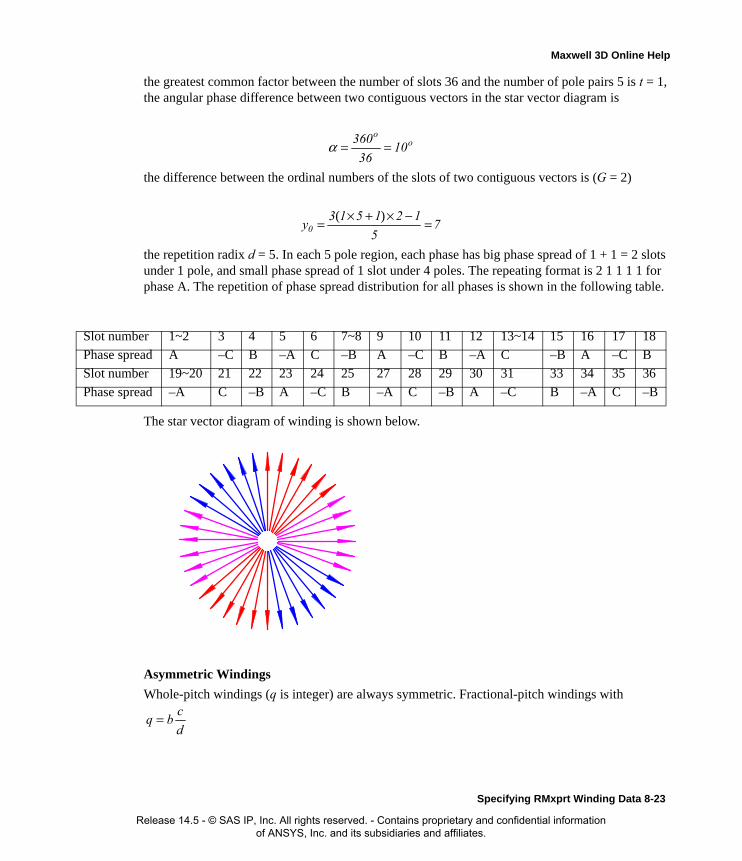
Maxwell 3D Online Help
the greatest common factor between the number of slots 36 and the number of pole pairs 5 is t = 1, the angular phase difference between two contiguous vectors in the star vector diagram is
the difference between the ordinal numbers of the slots of two contiguous vectors is (G = 2)
the repetition radix d = 5. In each 5 pole region, each phase has big phase spread of 1 + 1 = 2 slots under 1 pole, and small phase spread of 1 slot under 4 poles. The repeating format is 2 1 1 1 1 for phase A. The repetition of phase spread distribution for all phases is shown in the following table.
The star vector diagram of winding is shown below.
Asymmetric Windings
Whole-pitch windings (q is integer) are always symmetric. Fractional-pitch windings with
Slot number 1~2 3 4 5 6 7~8 9 10 11 12 13~14 15 16 17 18
Phase spread A –C B –A C –B A –C B –A C –B A –C B
Slot number 19~20 21 22 23 24 25 27 28 29 30 31 33 34 35 36
Phase spread –A C –B A –C B –A C –B A –C B –A C –B
oo
1036
360 ==α
75
121513y0 =−×+×= )(
d
cbq =
Specifying RMxprt Winding Data 8-23
Release 14.5 - © SAS IP, Inc. All rights reserved. - Contains proprietary and confidential information of ANSYS, Inc. and its subsidiaries and affiliates.
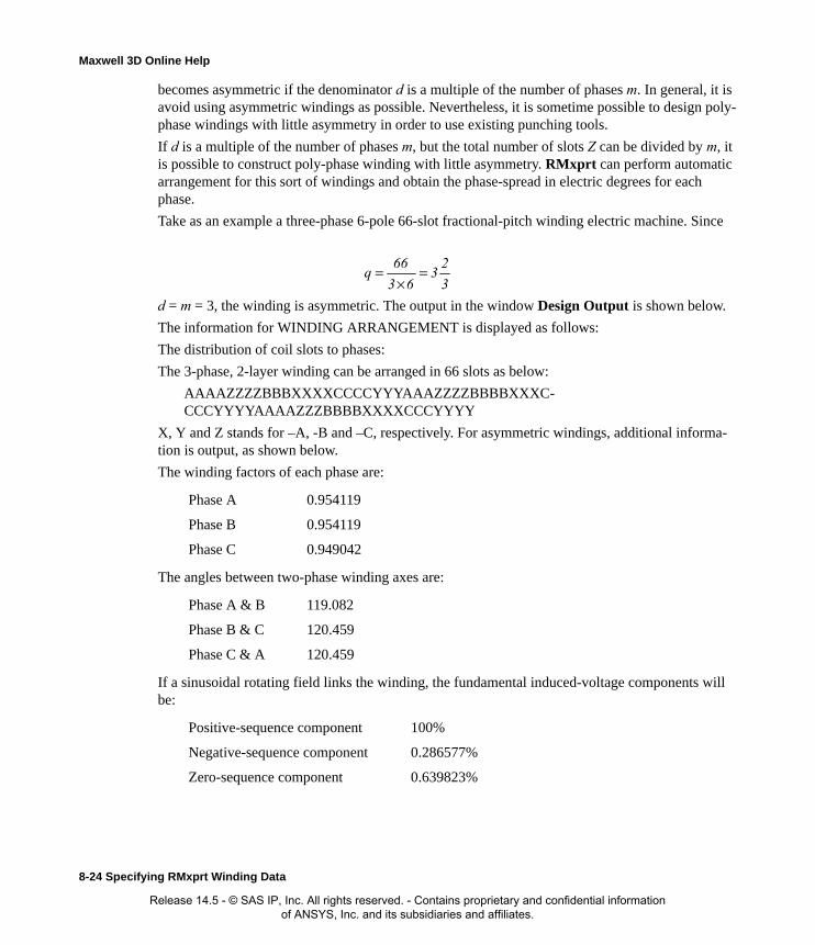
Maxwell 3D Online Help
becomes asymmetric if the denominator d is a multiple of the number of phases m. In general, it is avoid using asymmetric windings as possible. Nevertheless, it is sometime possible to design poly-phase windings with little asymmetry in order to use existing punching tools.
If d is a multiple of the number of phases m, but the total number of slots Z can be divided by m, it is possible to construct poly-phase winding with little asymmetry. RMxprt can perform automatic arrangement for this sort of windings and obtain the phase-spread in electric degrees for each phase.
Take as an example a three-phase 6-pole 66-slot fractional-pitch winding electric machine. Since
d = m = 3, the winding is asymmetric. The output in the window Design Output is shown below.
The information for WINDING ARRANGEMENT is displayed as follows:
The distribution of coil slots to phases:
The 3-phase, 2-layer winding can be arranged in 66 slots as below:
AAAAZZZZBBBXXXXCCCCYYYAAAZZZZBBBBXXXC-CCCYYYYAAAAZZZBBBBXXXXCCCYYYY
X, Y and Z stands for –A, -B and –C, respectively. For asymmetric windings, additional informa-tion is output, as shown below.
The winding factors of each phase are:
The angles between two-phase winding axes are:
If a sinusoidal rotating field links the winding, the fundamental induced-voltage components will be:
Phase A 0.954119
Phase B 0.954119
Phase C 0.949042
Phase A & B 119.082
Phase B & C 120.459
Phase C & A 120.459
Positive-sequence component 100%
Negative-sequence component 0.286577%
Zero-sequence component 0.639823%
3
23
63
66q =
×=
8-24 Specifying RMxprt Winding Data
Release 14.5 - © SAS IP, Inc. All rights reserved. - Contains proprietary and confidential information of ANSYS, Inc. and its subsidiaries and affiliates.

Maxwell 3D Online Help
Coil Connections
Connection of Double-layer Lap Windings
Every vector represents the top-layer effective side of a coil. The bottom effective side of the coil is determined based on the coil pitch, and is not displayed in the diagrams. Therefore, every vector in the diagrams can also stand for a coil. Connect all coils in phase spread of A in positive direction, and all coils in phase spread of –A in negative direction to form the phase A winding. In this way, phase B and C windings can also be connected. The winding connection layouts for the vector dia-grams are shown below.
Connection of Single-layer Half-coiled Windings
Every vector in A, B and C phase spread represents "go" effective side of a coil, the "return" effec-tive side of the coil is located in –A, –B and –C phase spread. For the lap type connection, all coils
Specifying RMxprt Winding Data 8-25
Release 14.5 - © SAS IP, Inc. All rights reserved. - Contains proprietary and confidential information of ANSYS, Inc. and its subsidiaries and affiliates.

Maxwell 3D Online Help
are with full coil pitch. The connection layouts of the lap type and the concentric type, with respect to the same vector drawing are shown below.
Connection of Single-layer Whole-coiled Windings
In the previous example, for the concentric type (lower right in the diagram), if coil 1 is not con-nected from slot 1 to slot 8 (long coil pitch: coil pitch = 7 > pole pitch = 6), but connected from slot 1 to slot 20, and slot 8 to slot 13, all coils of phase A winding have coil pitch of 5. In this way, the winding becomes single-layer whole-coiled type with the same star vector diagram and phase spread, and has much shorter average coil pitch. Therefore, single-layer whole-coiled windings consume less electromagnetic wire than single-layer half-coiled windings. RMxprt can optimize connections to minimize the average coil pitch to form a single-layer whole-coiled winding.
8-26 Specifying RMxprt Winding Data
Release 14.5 - © SAS IP, Inc. All rights reserved. - Contains proprietary and confidential information of ANSYS, Inc. and its subsidiaries and affiliates.

Maxwell 3D Online Help
An example of three-phase 4-pole 36-slot single-layer whole-coiled crossed lap-type winding (q = 3, 60o phase-spread) is shown below.
An example of three-phase 4-pole 36-slot single-layer whole-coiled crossed concentric-type wind-ing (q = 3, 60o phase-spread) is shown below.
A star vector diagram with fractional coil pitch can also be connected with single-layer whole-coiled type. When the number of slots per pole per phase q <2, as shown in the following vector diagram, the number of coil sets per phase may not equal to the number of poles (6 coils vs 10
Specifying RMxprt Winding Data 8-27
Release 14.5 - © SAS IP, Inc. All rights reserved. - Contains proprietary and confidential information of ANSYS, Inc. and its subsidiaries and affiliates.
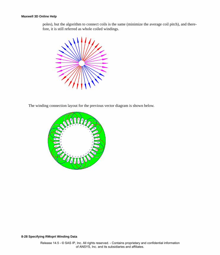
Maxwell 3D Online Help
poles), but the algorithm to connect coils is the same (minimize the average coil pitch), and there-fore, it is still referred as whole coiled windings.
The winding connection layout for the previous vector diagram is shown below.
8-28 Specifying RMxprt Winding Data
Release 14.5 - © SAS IP, Inc. All rights reserved. - Contains proprietary and confidential information of ANSYS, Inc. and its subsidiaries and affiliates.

Maxwell 3D Online Help
Another example is an asymmetric three-phase winding. The connection layout is shown below.
Connection of Double-pole Dual-speed WindingsCommonly used for coils of double-layer windings are lap- and concentric-types. Single-speed double-layer winding electric machine is usually connected as whole-coiled winding. Double-pole dual-speed electric machine is connected as double-layer whole-coiled winding at high speed and as double-layer half-coiled winding at low speed.
Take as an example a three-phase dual-speed 2/4-pole 24-slot double-layer winding. The arrange-ment of coils is shown in the Table and in the following figure.
Specifying RMxprt Winding Data 8-29
Release 14.5 - © SAS IP, Inc. All rights reserved. - Contains proprietary and confidential information of ANSYS, Inc. and its subsidiaries and affiliates.

Maxwell 3D Online Help
The connection for variation of number of poles is shown in the next figure. On the top-left is the 2-pole 2Y-connection at high speed, on the top-right is the 4-pole -connection at low speed.
Slot number 1 2 3 4 5 6 7 8 9 10 11 12
Two poles A A A A –C –C –C –C B B B B
Four poles A A A A C C C C B B B B
Slot number 13 14 15 16 17 18 19 20 21 22 23 24
Two poles –A –A –A –A C C C C –B –B –B –B
Four poles A A A A C C C C B B B B
8-30 Specifying RMxprt Winding Data
Release 14.5 - © SAS IP, Inc. All rights reserved. - Contains proprietary and confidential information of ANSYS, Inc. and its subsidiaries and affiliates.
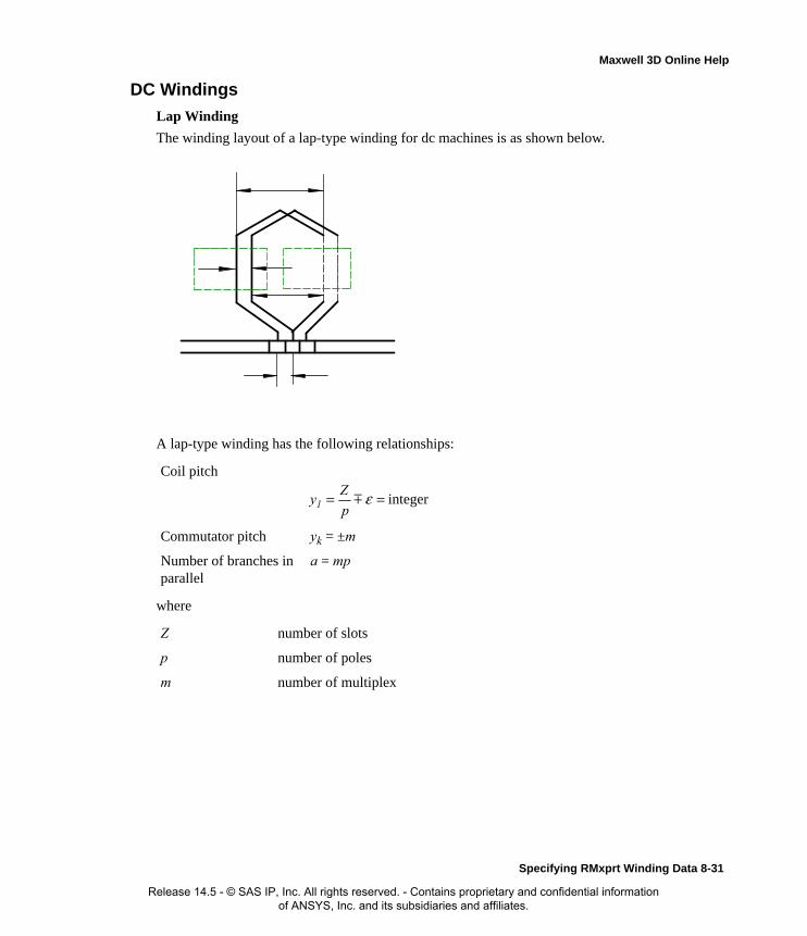
Maxwell 3D Online Help
DC Windings
Lap Winding
The winding layout of a lap-type winding for dc machines is as shown below.
A lap-type winding has the following relationships:
where
Coil pitch
Commutator pitch yk = ±m
Number of branches in parallel
a = mp
Z number of slots
p number of poles
m number of multiplex
integer== εp
Zy1
Specifying RMxprt Winding Data 8-31
Release 14.5 - © SAS IP, Inc. All rights reserved. - Contains proprietary and confidential information of ANSYS, Inc. and its subsidiaries and affiliates.

Maxwell 3D Online Help
Wave WindingThe winding layout of a wave-type winding for dc machines is as shown below.
A wave-type winding has the following relationships:
Frog-leg WindingA frog-leg winding consists of a lap winding and a wave winding. Assume the lap winding has m multiplex number. In order to connect the wave winding in parallel with the lap winding, the wave winding should have the same branch bake emf as the lap winding. Therefore, the number of branches in parallel of the wave winding has to be the same as that of the lap winding, or the multi-
Coil pitch
Commutator pitch
Number of branches in parallel
a = m
integer== εp
Zy1
integer/
==2p
mKyK
8-32 Specifying RMxprt Winding Data
Release 14.5 - © SAS IP, Inc. All rights reserved. - Contains proprietary and confidential information of ANSYS, Inc. and its subsidiaries and affiliates.

Maxwell 3D Online Help
plex number of the wave winding must be mp/2. The winding layout of a frog-leg-type winding with m=1 for dc machines is as shown below.
A frog-leg-type winding has the following relationships:
where
Coil pitch
Commutator pitch
yKa = ±m
Number of branch in parallel
a = pm
m number of multiplex (of the lap winding)
integer==+p
K2yy b1a1
integer==+p
K2yy KbKa
mp
K2yKb =
Specifying RMxprt Winding Data 8-33
Release 14.5 - © SAS IP, Inc. All rights reserved. - Contains proprietary and confidential information of ANSYS, Inc. and its subsidiaries and affiliates.

Maxwell 3D Online Help
Virtual SlotsWindings of the dc machine are usually double-layer type. In many cases, often a number of coil sides are imbedded into one slot for simplification of structure. Therefore, the number of slots Z is less than the number of coils S. There exists the relationship
where μ is the number of coil sides in each layer in one slot and is termed virtual slot factor. There-fore, the number of conductors per slots is equal to multiple of 2μ.
Equipotential ConnectorsThe points ideally possessing the same electric potential in armature winding are often wholly or partly connected by short copper wire, which is termed equipotential connector.
Equipotential Connector Class A of Simplex-lap Winding
Asymmetry in magnetic circuit, such as eccentric air-gap, causes circulating current in lap winding, increases losses and affects commutation in order. The equipotential connector Class A on the com-mutator of simplex-lap winding can solve this problem. The connection pitch of equipotential con-nector Class A of simplex-lap winding yp is equal to the number of commutator segments per pole pair.
Winding with yp = integer is termed symmetric winding. Only symmetric winding can have equi-potential connector Class A.
No need for Equipotential Connector for Simplex-wave Winding
Simplex-wave winding does not possess electrically equipotential points, therefore, can not have equipotential connector. On the other hand, simplex-wave winding does not need equipotential connector.
Equipotential Connector Class B of Multiplex-wave Winding
There are electric equipotential points among different sets of simplex-wave windings of multi-plex-wave winding. They can be connected to eliminate the nonuniform distribution of electric potential on commutator segments due to inequality of brush resistances. This is termed equipoten-tial connector Class B. The connection pitch of equipotential connector Class B of multiplex-wave winding yp is equal to the number of commutator segments per branch pair in parallel.
Equipotential Connector of Multiplex-lap Winding
For multiplex-lap winding, equipotential connector Class A is needed for each set of simplex-lap windings, equipotential connector Class B is needed among different sets of simplex-lap windings. There exist no electrically equipotential points among different sets of simplex-lap windings on the
μS
Z =
integer===a
K
p
Kyp
integer==a
Ky p
8-34 Specifying RMxprt Winding Data
Release 14.5 - © SAS IP, Inc. All rights reserved. - Contains proprietary and confidential information of ANSYS, Inc. and its subsidiaries and affiliates.

Maxwell 3D Online Help
commutator side of armature, however, there exist electrically equipotential points among different sets of simplex-lap windings on different sides of armature as points A and B in the figure below.
Those points can be connected by conductors passing through inside armature.
No Need for Equipotential Connector for Frog-leg Winding
For frog-leg winding, each pair of electrically equipotential points on commutator is connected by a lap coil and a wave coil in series. The connection acts as equipotential connector Class A for lap winding and as equipotential connector Class B for wave winding. Therefore there is no need for extra equipotential connectors.
Pole WindingsThe following two types of electric machines possess similar pole winding structure:
• DC machine (motor and generator)
• Three-phase synchronous machine (motor and generator)
Specifying RMxprt Winding Data 8-35
Release 14.5 - © SAS IP, Inc. All rights reserved. - Contains proprietary and confidential information of ANSYS, Inc. and its subsidiaries and affiliates.
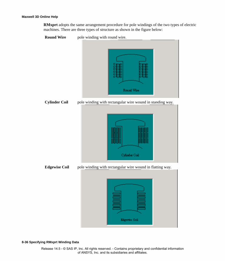
Maxwell 3D Online Help
RMxprt adopts the same arrangement procedure for pole windings of the two types of electric machines. There are three types of structure as shown in the figure below:
Round Wire pole winding with round wire.
Cylinder Coil pole winding with rectangular wire wound in standing way.
Edgewise Coil pole winding with rectangular wire wound in flatting way.
8-36 Specifying RMxprt Winding Data
Release 14.5 - © SAS IP, Inc. All rights reserved. - Contains proprietary and confidential information of ANSYS, Inc. and its subsidiaries and affiliates.

Maxwell 3D Online Help
Limited Space for Wire ArrangementBefore completing a winding arrangement, RMxprt needs to determine the limited space sizes for the winding. The limited sizes include: limited Overall Height, limited Overall Width and Wind-ing Clearance (the clearance between two adjacent pole windings), as shown below.
Overall Height, Overall Width and Winding Clearance can be input from RMxprt panel. If either Overall Height or Overall Width is set to 0, RMxprt perform automatic space optimization to obtain the maximum space for pole winding arrangement in the condition to guarantee the clear-ance between pole windings.
If the space from input or determined by space optimization is not sufficient to arrange for the input number of turns per pole, a message of "The rotor/shunt/series/commutating winding control dimension is not big enough." is displayed in Design Output window.
Winding Clearance
Overall Width
Overall Height
Specifying RMxprt Winding Data 8-37
Release 14.5 - © SAS IP, Inc. All rights reserved. - Contains proprietary and confidential information of ANSYS, Inc. and its subsidiaries and affiliates.
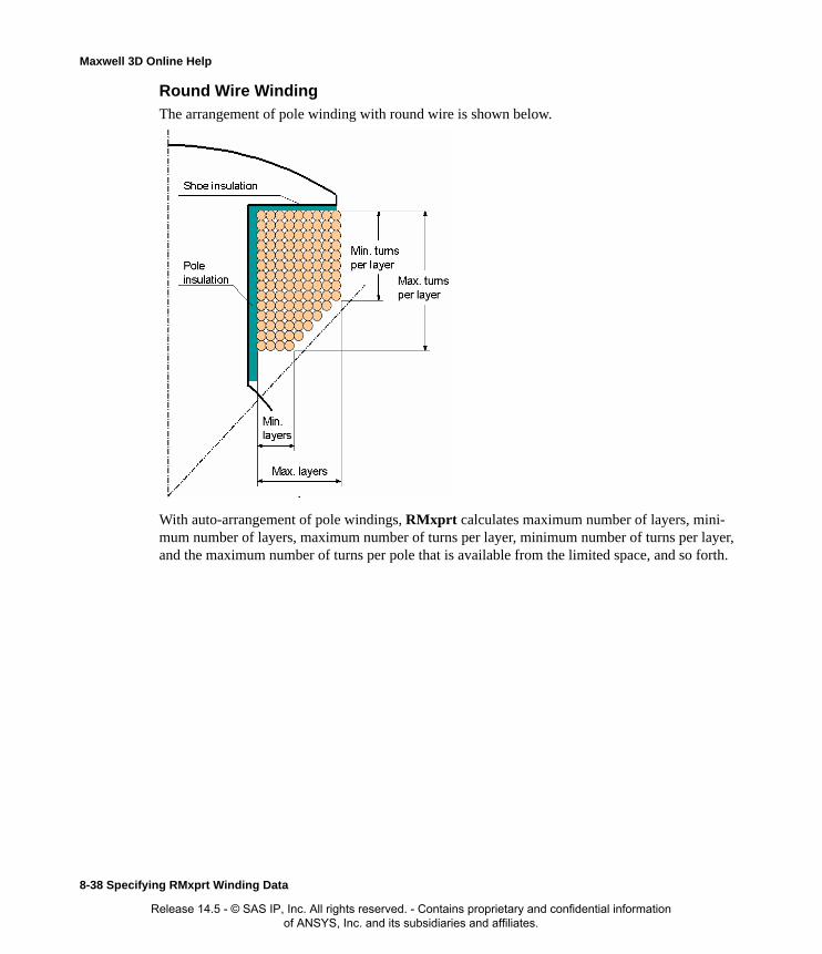
Maxwell 3D Online Help
Round Wire Winding
The arrangement of pole winding with round wire is shown below.
With auto-arrangement of pole windings, RMxprt calculates maximum number of layers, mini-mum number of layers, maximum number of turns per layer, minimum number of turns per layer, and the maximum number of turns per pole that is available from the limited space, and so forth.
8-38 Specifying RMxprt Winding Data
Release 14.5 - © SAS IP, Inc. All rights reserved. - Contains proprietary and confidential information of ANSYS, Inc. and its subsidiaries and affiliates.

Maxwell 3D Online Help
Cylinder Coil
The arrangement of magnetic-pole winding with rectangular wire wound in standing way by RMx-prt is shown below.
The cylinder coil is wound with half-turn over lapped layer by layer. Layers with the same number of turns constitute a section. The output window Design Output displays the number of layers and the number of turns per layer of each section, and the maximum number of turns per pole that is available from the limited space.
Specifying RMxprt Winding Data 8-39
Release 14.5 - © SAS IP, Inc. All rights reserved. - Contains proprietary and confidential information of ANSYS, Inc. and its subsidiaries and affiliates.

Maxwell 3D Online Help
Edgewise Coil
The arrangement of magnetic-pole winding with rectangular wire wound in flatting way by RMx-prt is shown below.
To guarantee the clearance between two adjacent pole windings, the wire width of the lower parts is decreased, while the wire thickness is increased to keep the sectional area of wire invariant as pos-sible. The turns with the same wire gauge constitute a section (maximum three sections are allowed). The output window Design Output displays the number of turns of each section and the sizes of wire gauge, and the maximum number of turns per pole that is available from the limited space.
Pole Winding with Half Turns
For some large machines, a half turn may be included due to too few turns per pole. When the num-ber of turns per pole is an integer number, the number of conductors per pole is an even number
8-40 Specifying RMxprt Winding Data
Release 14.5 - © SAS IP, Inc. All rights reserved. - Contains proprietary and confidential information of ANSYS, Inc. and its subsidiaries and affiliates.
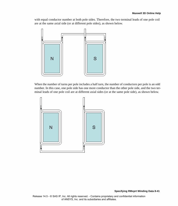
Maxwell 3D Online Help
with equal conductor number at both pole sides. Therefore, the two terminal leads of one pole coil are at the same axial side (or at different pole sides), as shown below.
When the number of turns per pole includes a half turn, the number of conductors per pole is an odd number. In this case, one pole side has one more conductor than the other pole side, and the two ter-minal leads of one pole coil are at different axial sides (or at the same pole side), as shown below.
Specifying RMxprt Winding Data 8-41
Release 14.5 - © SAS IP, Inc. All rights reserved. - Contains proprietary and confidential information of ANSYS, Inc. and its subsidiaries and affiliates.

Maxwell 3D Online Help
Exporting Winding DataWinding data may be export to a table:
1. Select the Machine>Winding>Export Layout command from the menu. You may also right-click in the Winding Editor window and select Export Layout from the shortcut menu.
2. Browse to the location to save the file and enter a filename.
3. Click Save to export the winding data to a file and dismiss the dialog.
Note The winding must be editable for the Export Layout command to be available. If you are using a standard winding, you can switch to the Winding Editor by:
1. Click on the winding in the Project Tree window.
2. In the Properties Window, click on the button next to Winding Type.
The Winding Type dialog is displayed.
3. Select Editor as the winding type and click OK.
8-42 Specifying RMxprt Winding Data
Release 14.5 - © SAS IP, Inc. All rights reserved. - Contains proprietary and confidential information of ANSYS, Inc. and its subsidiaries and affiliates.

9
RMxprt Machine Types
Using RMxprt, you can simulate and analyze the following thirteen machine types:
• Adjust-Speed Synchronous Machine
• Brushless Permanent-Magnet DC Motor
• Claw-Pole Alternator
• General DC Machine
• Generic Rotating Machine
• Line-Start Permanent-Magnet Synchronous Motor
• Permanent-Magnet DC Motor
• Single-Phase Induction Motor
• Switched Reluctance Motor
• Three-Phase Induction Motor
• Three-Phase Non-Salient Synchronous Machine
• Three-Phase Synchronous Machine
• Universal Motor
RMxprt Machine Types 9-1
Release 14.5 - © SAS IP, Inc. All rights reserved. - Contains proprietary and confidential information of ANSYS, Inc. and its subsidiaries and affiliates.
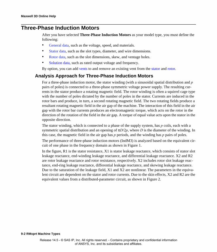
Maxwell 3D Online Help
Three-Phase Induction MotorsAfter you have selected Three-Phase Induction Motors as your model type, you must define the following:
• General data, such as the voltage, speed, and materials.
• Stator data, such as the slot types, diameter, and wire dimensions.
• Rotor data, such as the slot dimensions, skew, and ventage holes.
• Solution data, such as rated output voltage and frequency.
By option, you can add vents to and remove an existing vent from the stator and rotor.
Analysis Approach for Three-Phase Induction MotorsFor a three-phase induction motor, the stator winding (with a sinusoidal spatial distribution and p pairs of poles) is connected to a three-phase symmetric voltage power supply. The resulting cur-rents in the stator produce a rotating magnetic field. The rotor winding is often a squirrel cage type with the number of poles dictated by the number of poles in the stator. Currents are induced in the rotor bars and produce, in turn, a second rotating magnetic field. The two rotating fields produce a resultant rotating magnetic field in the air gap of the machine. The interaction of this field in the air gap with the rotor bar currents produces an electromagnetic torque, which acts on the rotor in the direction of the rotation of the field in the air gap. A torque of equal value acts upon the stator in the opposite direction.
The stator winding, which is connected to a phase of the supply system, has p coils, each with a symmetric spatial distribution and an opening of πD/2p, where D is the diameter of the winding. In this case, the magnetic field in the air gap has p periods, and the winding has p pairs of poles.
The performance of three-phase induction motors (IndM3) is analyzed based on the equivalent cir-cuit of one phase in the frequency domain as shown in Figure 1.
In the figure, R1 is the stator resistance, X1 is stator leakage reactance, which consists of stator slot leakage reactance, end-winding leakage reactance, and differential leakage reactance. X2 and R2 are rotor leakage reactance and rotor resistance, respectively. X2 includes rotor slot leakage reac-tance, end-ring leakage reactance, differential leakage reactance, and skewing leakage reactance. Due to the saturation of the leakage field, X1 and X2 are nonlinear. The parameters in the equiva-lent circuit are dependent on the stator and rotor currents. Due to the skin effects, X2 and R2 are the equivalent values from a distributed-parameter circuit, as shown in Figure 2.
9-2 RMxprt Machine Types
Release 14.5 - © SAS IP, Inc. All rights reserved. - Contains proprietary and confidential information of ANSYS, Inc. and its subsidiaries and affiliates.

Maxwell 3D Online Help
They vary with the rotor slip s. All rotor parameters have been referred to the stator side.
In the exciting branch, Xm is the magnetizing reactance, and RFe is the resistance corresponding to iron-core losses. Xm is a linearized nonlinear parameter that varies with the saturation of the main field.
After a phase voltage U1 is applied to the phase terminals, stator phase current I1 and rotor current I2, which has been referred to the stator, can be easily computed by the circuit analysis. The elec-tromagnetic power Pm, or air-gap power, is computed by the following:
Pm = 3 * I2^2 * R2/s
The electromagnetic torque Tm is:
Tm = Pm/
where w is the synchronous speed in rad/s.
The output mechanical shaft torque T2 is:
T2 = Tm - Tfw
where Tfw is the frictional and wind torque.
The output power is:
P2 = T2 * 2
where 2 = * (1 - s) and is rotor speed in rad/s.
The input power is:
P1 = P2 + Pfw + Pcu2 + PFe + Pcu1 + Ps
where Pfw, Pcu2, PFe, Pcu1, and Ps are frictional and wind loss, rotor copper loss, iron-core loss, stator copper loss, and stray loss, respectively.
The power factor is derived from:
PF = P1/(m * U1 * I1)
The efficiency is computed by:
eff = P2/P1 * 100%
Figure 1 Figure 2
ω
ω
ω ω
RMxprt Machine Types 9-3
Release 14.5 - © SAS IP, Inc. All rights reserved. - Contains proprietary and confidential information of ANSYS, Inc. and its subsidiaries and affiliates.
Maxwell 3D Online Help
Defining a Three-Phase Induction MotorThe general procedure for defining a three-phase induction motor is as follows:
1. Insert a three-phase induction motor into an existing or new project.
2. Double-click the Machine entry in the project tree to define the general data, such as the num-ber of poles and machine losses.
3. Double-click the Machine-Stator entry in the project tree to define the stator geometry.
4. Double-click the Machine-Stator-Slot entry in the project tree to define the stator slot dimen-sions.
5. Double-click the Machine-Stator-Winding entry in the project tree to define the stator wind-ings and conductors.
6. Double-click the Machine-Rotor entry in the project tree to define the rotor geometry.
7. Double-click the Machine-Rotor-Slot entry in the project tree to define the rotor slot dimen-sions.
8. Double-click the Machine-Rotor-Winding entry in the project tree to define the rotor conduc-tor, ventage hole dimensions, and skew.
9. Double-click the Machine-Shaft entry in the project tree to define the magnetism of the shaft.
10. Right-click Analysis in the project tree, and click Add Solution Setup to define the solution data.
11. Choose File>Save to save the project.
12. Choose RMxprt>Analyze to analyze the design.
Once the design is analyzed, the model can be viewed in the Maxwell 2D Modeler, or it can be used to create a new Maxwell 2D project, and a new Maxwell 3D design.
Please refer to the Three-Phase Induction Motor Problem application note, on the technical support page of the ANSYS web site, for a specific example of a three-phase induction motor problem.
Defining the General Data for a Three Phase Induction MotorUse the General Data Properties window to define the basic parameters of the induction motor, such as the number of poles, and frictional loss.
To define the general data:
1. To open the General Data Properties window, double-click the Machine entry in the project tree on the desktop. (You can also enter values in the Properties section of the desktop without opening a separate window.)
2. Enter the number of poles for the machine in the Number of Poles field. This value is the total number of poles in the stator (or the number of pole pairs multiplied by two).
3. Enter the stray loss factor in the Stray Loss Factor field. The stray load loss consists of the losses arising from non-uniform current distribution in the copper and additional core losses
Note When you place the cursor over an entry field in the data windows, a brief description of that field appears in the status bar at the bottom of the RMxprt window.
9-4 RMxprt Machine Types
Release 14.5 - © SAS IP, Inc. All rights reserved. - Contains proprietary and confidential information of ANSYS, Inc. and its subsidiaries and affiliates.
Maxwell 3D Online Help
produced in the iron by distortion of the magnetic flux by the load current. The IEEE Standard provides different assumed stray load loss values for AC motors rated less than 2500 hp, as fol-lows:
• 1) 1-125 HP = 1.8% of rated output power
• 2) 126-500 HP = 1.5%
• 3) 501-2499 HP = 1.2%
4. Enter the energy loss due to friction at the given speed in the Frictional Loss field.
5. Enter the wind loss due to air resistance measured at the reference speed in the Wind Loss field.
6. Enter the given speed in the Reference Speed field.
7. Click OK to close the Properties window.
General Data for Three-Phase Induction Motors
To access the general data, double-click the Machine entry in the project tree.
The General Data Properties window for a three-phase induction motor contains the following fields:
Defining the Stator Data for a Three-Phase Induction Motor
The stator is the outer lamination stack where the three-phase windings reside. In the project tree, double-click Machine>Stator, Machine-Stator-Slot, and Machine-Stator-Winding to define the physical dimensions, slot data, wires, and conductors for the stator.
TTo define general stator data:
1. To open the Stator Data Properties window, double-click the Machine>Stator entry in the project tree on the desktop. (You can also enter values in the Properties section of the desktop without opening a separate window.)
2. Enter the Outer Diameter of the stator.
3. Enter the Inner Diameter of the stator.
4. Enter the length of the stator core in the Length field.
5. Enter the stacking factor for the stator core in the Stacking Factor field.
6. Select a Steel Type for the stator core:
Machine Type The machine type you selected when inserting a new RMxprt design (Three Phase Induction Motor).
Number of Poles The number of poles the machine contains.
Stray Loss Factor The stray loss factor: the ratio of stray loss to rated output power.
Frictional Loss The frictional energy loss (due to friction) measured at the reference speed.
Wind Loss The wind loss (due to air resistance) measured at the reference speed.
Reference Speed The given speed of reference.
RMxprt Machine Types 9-5
Release 14.5 - © SAS IP, Inc. All rights reserved. - Contains proprietary and confidential information of ANSYS, Inc. and its subsidiaries and affiliates.

Maxwell 3D Online Help
a. Click the button for Steel Type.The Select Definition window appears.
b. Select a steel type from the list, or define a new steel type.
c. Click OK to close the Select Definition window and return to the Properties window.
7. Enter the Number of Slots in the stator.
8. Select the Slot Type:
a. Click the button for the Slot Type.
The Select Slot Type window appears.
b. Select a slot type (available types include 1 through 4).
Optionally, check User Defined Slot if you wish to define the slot dimensions using the Slot Editor.
c. Click OK to close the Select Slot Type window and return to the Properties window.
9. Enter the number of sectors in the Lamination Sectors field.
10. Enter the thickness of the magnetic end pressboard in the Pressboard Thickness field. Enter 0 for a non-magnetic end pressboard.
11. Enter the skew width, measured in slot number, in the Skew Width field.
12. Click OK to close the Properties window.
Stator Data for Three-Phase Induction Motors
To access the general stator data, double-click the Machine>Stator entry in the project tree.
The Stator Data Properties window contains the following fields:
Note When you place the mouse cursor over the slot type, a schematic of the selected type appears, displaying the slot dimension variables.
Outer Diameter The outer diameter of the stator core.
Inner Diameter The inner diameter of the stator core.
Length The length of the stator core.
Stacking Factor The stacking factor of the stator core.
Steel Type The steel type of the stator core. Click the button to open the Select Definition window.
Number of Slots The number of slots the stator core contains.
Slot Type The type of slots in the stator core. Click the button to open the Select Slot Type window.
Lamination Sectors
The number of lamination sectors.
Pressboard Thickness
The magnetic press board thickness (0 for a non-magnetic press board).
Skew Width The skew width measured in slot number.
9-6 RMxprt Machine Types
Release 14.5 - © SAS IP, Inc. All rights reserved. - Contains proprietary and confidential information of ANSYS, Inc. and its subsidiaries and affiliates.

Maxwell 3D Online Help
Defining the Stator Slots for a Three-Phase Induction Motor
To define the stator slots:
1. To open the Stator Slot Data Properties window, double-click the Machine-Stator-Slot entry in the project tree on the desktop. (You can also enter values in the Properties section of the desktop without opening a separate window.)
2. Optionally, to automatically design the dimensions of slots Hs2, Bs1, and Bs2, select the Auto Design check box.
3. Optionally, to design dimensions of slots Bs1 and Bs2 based on the stator tooth width, select the Parallel Tooth check box, and enter a value in the Tooth Width field.
4. Enter the available slot dimensions.
5. Click OK to close the Properties window.
Stator Slot Data for Three-Phase Induction Motors
To access the stator slot data, double-click the Machine-Stator-Slot entry in the project tree.
The Stator Slot Data Properties window contains the following fields:
Note If you chose User Defined Slot in the Select Slot Type window, you must define the slot dimensions using the Slot Editor.
Hs0 Always available.
Hs2 Available only when Auto Design is cleared. When Auto Design is selected, this slot dimension is determined automatically.
Bs0 Always available.
Bs1 Available only when Auto Design and Parallel Tooth are both cleared. When Auto Design is selected, this slot dimension is determined automatically. When Parallel Tooth is selected, this slot dimension is determined based on the value entered in the Tooth Width field.
Bs2 Available only when Auto Design and Parallel Tooth are both cleared. When Auto Design is selected, this slot dimension is determined automatically. When Parallel Tooth is selected, this slot dimension is determined based on the value entered in the Tooth Width field.
Rs Rs is added when the slot type is 3 or 4.
Auto Design Select or clear this to enable or disable auto-design of slots Hs2, Bs1, and Bs2. When this check box is selected, only two other fields appear in the window: Hs0 and Bs0.
Parallel Tooth
Select this to design Bs1 and Bs2 based on the tooth width. When this check box is selected, the Bs1 and Bs2 fields are removed, and the Tooth Width field is added.
Tooth WidthThe tooth width for the parallel tooth, on which Bs1 and Bs2 are designed.
RMxprt Machine Types 9-7
Release 14.5 - © SAS IP, Inc. All rights reserved. - Contains proprietary and confidential information of ANSYS, Inc. and its subsidiaries and affiliates.

Maxwell 3D Online Help
Defining the Stator Windings for a Three-Phase Induction MotorDefine the wires, conductors, insulation, and windings of the stator.
To define the wires and windings:
1. To open the Stator Slot Winding Properties window, double-click the Machine-Stator-Winding entry in the project tree on the desktop. (You can also enter values in the Properties section of the desktop without opening a separate window.)
2. Click the Winding tab.
3. Enter the number of layers in the stator winding in the Winding Layers field.
4. Select a Winding Type:
a. Click the button for Winding Type.The Winding Type window appears.
b. Select from one of the following three types of winding:
• Whole Coiled
• Half Coiled
• Editor
Hs0 A slot dimension (see the diagram shown in the modeling window when Machine-Stator-Slot is selected).
Hs2 A slot dimension (see the diagram shown in the modeling window when Machine-Stator-Slot is selected).
Bs0 A slot dimension (see the diagram shown in the modeling window when Machine-Stator-Slot is selected).
Bs1 A slot dimension (see the diagram shown in the modeling window when Machine-Stator-Slot is selected).
Bs2 A slot dimension (see the diagram shown in the modeling window when Machine-Stator-Slot is selected).
Rs A slot dimension. (see the diagram shown in the modeling window when Machine-Stator-Slot is selected). Rs is added when the slot type is 3 or 4.
9-8 RMxprt Machine Types
Release 14.5 - © SAS IP, Inc. All rights reserved. - Contains proprietary and confidential information of ANSYS, Inc. and its subsidiaries and affiliates.

Maxwell 3D Online Help
When you place the mouse cursor over a winding button, an outline of the selected wind-ing appears. The following table describes the six types of windings that are possible (three for one-layer and three for two-layer):
Type Description
One layer
winding Editor
A user-defined one-layer winding arrangement. You need to set up the winding arrangement for each slot.
Whole Coiled
A one-layer whole-coiled winding:
123Slot
RMxprt Machine Types 9-9
Release 14.5 - © SAS IP, Inc. All rights reserved. - Contains proprietary and confidential information of ANSYS, Inc. and its subsidiaries and affiliates.

Maxwell 3D Online Help
Half Coiled
A one-layer concentric half-coiled winding:
Two Layer
Winding Editor
A user-defined two-layer winding arrangement. When you select for winding layers the you can specify a different winding arrangement for each slot in the Winding Editor.
Whole Coiled
A two-layer whole coiled winding:
The phase belt for this winding configuration is equal to 360/2m, where m is the phase number.
123Slot
123Slot
9-10 RMxprt Machine Types
Release 14.5 - © SAS IP, Inc. All rights reserved. - Contains proprietary and confidential information of ANSYS, Inc. and its subsidiaries and affiliates.
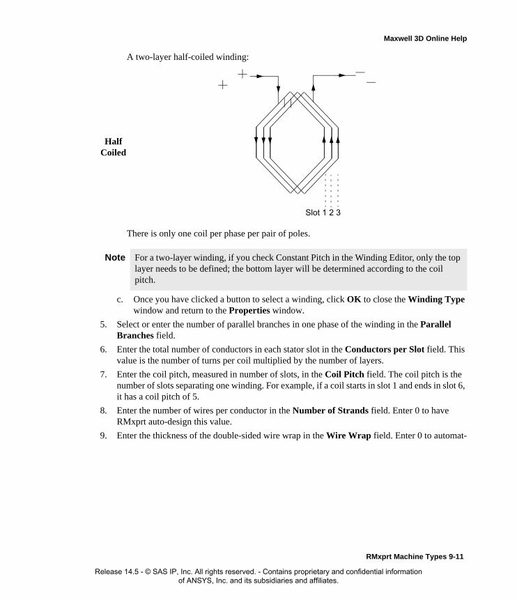
Maxwell 3D Online Help
c. Once you have clicked a button to select a winding, click OK to close the Winding Type window and return to the Properties window.
5. Select or enter the number of parallel branches in one phase of the winding in the Parallel Branches field.
6. Enter the total number of conductors in each stator slot in the Conductors per Slot field. This value is the number of turns per coil multiplied by the number of layers.
7. Enter the coil pitch, measured in number of slots, in the Coil Pitch field. The coil pitch is the number of slots separating one winding. For example, if a coil starts in slot 1 and ends in slot 6, it has a coil pitch of 5.
8. Enter the number of wires per conductor in the Number of Strands field. Enter 0 to have RMxprt auto-design this value.
9. Enter the thickness of the double-sided wire wrap in the Wire Wrap field. Enter 0 to automat-
Half Coiled
A two-layer half-coiled winding:
There is only one coil per phase per pair of poles.
Note For a two-layer winding, if you check Constant Pitch in the Winding Editor, only the top layer needs to be defined; the bottom layer will be determined according to the coil pitch.
1 2 3Slot
RMxprt Machine Types 9-11
Release 14.5 - © SAS IP, Inc. All rights reserved. - Contains proprietary and confidential information of ANSYS, Inc. and its subsidiaries and affiliates.
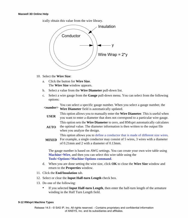
Maxwell 3D Online Help
ically obtain this value from the wire library.
10. Select the Wire Size:
a. Click the button for Wire Size.The Wire Size window appears.
b. Select a value from the Wire Diameter pull-down list.
c. Select a wire gauge from the Gauge pull-down menu. You can select from the following options:
The gauge number is based on AWG settings. You can create your own wire table using Machine>Wire, and then you can select this wire table using the Tools>Options>Machine Options command.
d. When you are done setting the wire size, click OK to close the Wire Size window and return to the Properties window.
11. Click the End/Insulation tab.
12. Select or clear the Input Half-turn Length check box.
13. Do one of the following:
• If you selected Input Half-turn Length, then enter the half-turn length of the armature winding in the Half Turn Length field.
<number>You can select a specific gauge number. When you select a gauge number, the Wire Diameter field is automatically updated.
USERThis option allows you to manually enter the Wire Diameter. This is useful when you want to enter a diameter that does not correspond to a particular wire gauge.
AUTO
This option sets the Wire Diameter to zero, and RMxprt automatically calculates the optimal value. The diameter information is then written to the output file when you analyze the design.
MIXED
This option allows you to define a conductor that is made of different size wires. For example, a single conductor may consist of 5 wires, 3 wires with a diameter of 0.21mm and 2 with a diameter of 0.13mm.
Insulation
Conductor
y
Wire Wrap = 2*y
9-12 RMxprt Machine Types
Release 14.5 - © SAS IP, Inc. All rights reserved. - Contains proprietary and confidential information of ANSYS, Inc. and its subsidiaries and affiliates.

Maxwell 3D Online Help
g
• If you cleared Input Half-turn Length, then enter the end length adjustment of the stator coils in the End Adjustment field. The end adjustment is the distance one end of the con-ductor extends vertically beyond the end of the stator.
14. Enter the inner radius of the base corner in the Base Inner Radius field.
15. Enter the inner diameter of the coil tip in the Tip Inner Diameter field.
16. Enter the distance between two stator coils in the End Clearance field.
17. Enter the thickness of the slot liner insulation in the Slot Liner field.
18. Enter the thickness of the wedge insulation in the Wedge Thickness field.
19. Enter the thickness of the insulation layer in the Layer Insulation field.
20. Enter the limited slot fill factor for the wire design in the Limited Fill Factor field.
21. Click OK to close the Properties window.
Stator Winding Data for Three-Phase Induction MotorsTo access the stator winding data, double-click the Machine-Stator-Winding entry in the project tree.
The Stator Winding Data Properties window contains the following fields:
Winding tabWinding Layers The number of winding layers.
Winding Type The type of stator winding. Click the button to open the WindinType window and choose from Whole Coiled, Half Coiled, andEditor.
Parallel Branches The number of parallel branches in the stator winding.
Conductors per Slot
The number of conductors per stator slot (0 for auto-design).
EndAdjustment
StatorCoil
End of Stator
RMxprt Machine Types 9-13
Release 14.5 - © SAS IP, Inc. All rights reserved. - Contains proprietary and confidential information of ANSYS, Inc. and its subsidiaries and affiliates.

Maxwell 3D Online Help
t
e e
Coil Pitch The coil pitch measured in number of slots.
Number of Strands
The number of wires per conductor (0 for auto-design).
Wire Wrap The thickness of the double-sided wire wrap (0 to automatically obtain this value from the wire library).
Wire Size The diameter of the wire (0 for auto-design). Click the button toopen the Wire Size window where you can specify units, wire type, diameter, and gauge.
End/Insulation tab
Input Half-turn Length
Select or clear this check box to specify whether or not you wanto enter the half-turn length. When this check box is selected, theHalf Turn Length field appears the next time you open the Properties window. When this check box is selected, the End Adjustment field appears instead.
Half Turn LengthThe half-turn length of the armature winding.
End Adjustment The end length adjustment of the stator coils, which is the distancone end of the conductor extends vertically beyond the end of thstator.
Base Inner Radius
The inner radius of the base corner.
Tip Inner Diameter
The inner diameter of the coil tip.
End Clearance The end clearance between two adjacent coils.
Slot Liner The thickness of the slot liner insulation.
Wedge Thickness The thickness of the wedge insulation.
Layer Insulation The thickness of the insulation layer.
Limited Fill Factor
The limited slot fill factor for the wire design.
9-14 RMxprt Machine Types
Release 14.5 - © SAS IP, Inc. All rights reserved. - Contains proprietary and confidential information of ANSYS, Inc. and its subsidiaries and affiliates.

Maxwell 3D Online Help
Winding Editor for a Three-Phase Induction Motor
For a three-phase induction motor, you may want to specify a different number of conductors for each stator slot. The Winding Editor makes this possible by enabling you to specify the number of turns for each coil. To enable the Winding Editor, you must have set the Winding Property for the Winding Type to Editor.
To specify the number of turns for each coil:
1. Click Machine>Winding>Edit Layout.The Winding Editor window appears.
2. In the table in the upper left, set which phase you want for each coil and which slot is the “in” and “out” slot for the current in each coil.
3. If you are working on a quarter or half model, you may want to specify a multiplier by clicking the Periodic Multiplier check box and specifying a value.
4. Select or deselect the Constant Turns or Constant Pitch check boxes, depending on whether you want to be able to change these setting in the table above. When these options are selected, you cannot change the turns or pitch.
5. When you are satisfied with the coil settings, click OK to close the Winding Editor window.
Defining Different Size Wires for a Three-Phase Induction MotorUse the Gauge option if you have a conductor that is made up different size wires.
To define different size wires:
1. In the Wire Size window, select MIXED from the Gauge pull-down menu.
2. Select either Round or Rectangular as the Wire Type.
3. Enter the appropriate wire data in the table:
• For a round wire:
• Enter the Diameter in the table.
• Enter a Number in the table to specify how many of the conductor’s wires have this diameter.
• For a rectangular wire:
• Enter the Width of the wire in the table.
• Enter the Thickness of the wire in the table.
• Enter the Fillet value in the table.
• Enter a Number in the table to specify how many of the conductor’s wires have this data.
4. Choose Add to add the new wire data.
5. Repeat steps 3 and 4 for each size wire you want to add.
RMxprt Machine Types 9-15
Release 14.5 - © SAS IP, Inc. All rights reserved. - Contains proprietary and confidential information of ANSYS, Inc. and its subsidiaries and affiliates.

Maxwell 3D Online Help
6. When you are finished defining the wires, click OK to close the Wire Size window.
Stator Vent Data for Three-Phase Induction Motors
By option, you can add a vent to a three-phase induction motor. To add a vent to stator in a three-phase induction motor.
1. Select the stator icon in the project tree.
2. Right-click to display the pop-up menu and select Insert Vent.
The vent icon appears in the project tree under the stator.
To remove a vent to stator in a three-phase induction motor.
1. Select the stator icon in the project tree.
2. Right-click to display the pop-up menu and select Remove Vent.
The vent icon disappears in the project tree under the stator.
The Vent data for the stator includes the following fields.
Defining the Rotor Data for a Three-Phase Induction Motor
The rotor consists of copper bars in which current is induced by the magnetic fields produced by the stator windings. In the project tree, double-click Machine-Rotor, Machine-Rotor-Slot, and Machine-Rotor-Winding to define the rotor slots and vents.
To define general stator data:
1. To open the Rotor Data Properties window, double-click the Machine>Rotor entry in the project tree on the desktop. (You can also enter values in the Properties section of the desktop without opening a separate window.)
2. Enter the stacking factor for the rotor core in the Stacking Factor field.
3. Enter the Number of Slots in the rotor.
4. Select the Slot Type:
a. Click the button for the Slot Type.
Note For example, if one conductor is made up of 5 wires, and 3 of those wires have a diameter of 0.21mm, and the other 2 have a diameter of 0.13mm, then the mixed wire size table will have two lines. The first line will list Diameter = 0.21 and Number = 3. The second line will list Diameter = 0.13 and Number = 2. An equivalent wire diameter is displayed as Wire Size value in the Winding tab in the Properties window.
Vent Ducts Number of radial vent ducts
Duct Width Width of radial vent ducts
Magnetic Spacer Width Width of magnetic spacer which holds vent ducts. 0 for non magnetic spacer
Duct Pitch Center-to-Center distance between two adjacent Vent ducts
9-16 RMxprt Machine Types
Release 14.5 - © SAS IP, Inc. All rights reserved. - Contains proprietary and confidential information of ANSYS, Inc. and its subsidiaries and affiliates.

Maxwell 3D Online Help
The Select Slot Type window appears.
b. Select a slot type (available types include 1 through 4).
c. Click OK to close the Select Slot Type window and return to the Properties window.
5. Enter the outer diameter of the rotor in the Outer Diameter field.
6. Enter the inner diameter of the rotor in the Inner Diameter field.
7. Enter the length of the rotor core in the Length field.
8. Select a Steel Type for the rotor core:
a. Click the button for Steel Type.The Select Definition window appears.
b. Select a steel type from the list, or define a new steel type.
c. Click OK to close the Select Definition window and return to the Properties window.
9. Enter the Skew Width, measured in rotor slot pitch. This value defines by how much the rotor bars are skewed.
10. Optionally, select Cast Rotor to allow the conductor to fill all the space available in the slot. Otherwise, RMxprt assumes the slot wedge that fixes the bars is filled with insulator material in a 2D/3D geometry model.
11. Optionally, select Half Slot to draw only half of the rotor slots.
12. Optionally, select Double Cage to specify the winding as a double-squirrel-cage winding.
If you select Double Cage, another line appears in the properties to let you specify the Bottom Slot type.
a. Click on the Custom button on the Double Cage row. This displays the Select Slot Type window. The Select Slot Type window appears.
b. Select a slot type (available types include 1 through 4).
13. Click OK to close the Properties window.
Rotor Data for Three-Phase Induction Motors
To access the general rotor data, double-click the Machine>Rotor entry in the project tree.
Note When you place the mouse cursor over the slot type, a schematic of the selected type appears, displaying the slot dimension variables.
Note When you place the mouse cursor over the slot type, a schematic of the selected type appears, displaying the slot dimension variables.
RMxprt Machine Types 9-17
Release 14.5 - © SAS IP, Inc. All rights reserved. - Contains proprietary and confidential information of ANSYS, Inc. and its subsidiaries and affiliates.
Maxwell 3D Online Help
The Rotor Data Properties window contains the following fields:
Defining the Rotor Slots for a Three-Phase Induction MotorTo define the type and dimensions of the rotor’s slots:
1. To open the Rotor Data Slot Properties window, double-click the Machine-Rotor-Slot entry in the project tree on the desktop. (You can also enter values in the Properties section of the desktop without opening a separate window.)
2. Enter the slot dimensions in the following fields: Hs0, Hs01, Hs2, Bs0, Bs1, Bs2, Rs.
3. Click OK to close the Properties window.
Rotor Slot Data for Three-Phase Induction MotorsTo access the rotor slot data, double-click the Machine-Rotor-Slot entry in the project tree.
The Rotor Slot Data Properties window contains the following fields:
Stacking Factor The stacking factor of the rotor core.
Number of Slots The number of slots the rotor core contains.
Slot Type The type of slots in the rotor core. Click the button to open the Select Slot Type window.
Outer Diameter The outer diameter of the rotor core.
Inner Diameter The inner diameter of the rotor core.
Length The length of the rotor core.
Steel Type The steel type of the rotor core. Click the button to open the Select Definition window.
Skew Width The skew width measured in slot number.
Cast Rotor Select or clear this to specify whether the rotor squirrel-cage winding is cast or not.
Half Slot Select this to specify a half-shaped unsymmetrical slot.
Double Cage Select this to specify the winding as double-squirrel-cage.
Hs0 A slot dimension (see the diagram shown in the modeling window when Machine-Rotor-Slot is selected).
Hs01 A slot dimension (see the diagram shown in the modeling window when Machine-Rotor-Slot is selected).
Hs2 A slot dimension (see the diagram shown in the modeling window when Machine-Rotor-Slot is selected).
Bs0 A slot dimension (see the diagram shown in the modeling window when Machine-Rotor-Slot is selected).
9-18 RMxprt Machine Types
Release 14.5 - © SAS IP, Inc. All rights reserved. - Contains proprietary and confidential information of ANSYS, Inc. and its subsidiaries and affiliates.
Maxwell 3D Online Help
Defining the Rotor Winding for a Three-Phase Induction MotorTo define the rotor winding data:
1. To open the Rotor Data Slot Properties window, double-click the Machine-Rotor-Winding entry in the project tree on the desktop. (You can also enter values in the Properties section of the desktop without opening a separate window.)
2. Select a Bar Conductor Type for the rotor winding bar:
a. Click the button for Bar Conductor Type.The Select Definition window appears.
b. Select a conductor type from the list, or define a new conductor type.
c. Click OK to close the Select Definition window and return to the Properties window.
3. Enter the length of the gap between the end ring and the iron core in the End Length field. This field specifies the value for only one end of the gap, not both.
4. Enter the end ring dimension in the axial direction in the End-Ring Width field. The end ring connects the bars of the rotor to one another.
5. Enter the end ring dimension in the radius direction in the End-Ring Height field. The end ring’s height covers at least the cross section of the rotor conductor.
6. Select an End Ring Conductor Type for the rotor winding end ring:
a. Click the button for End Ring Conductor Type.The Select Definition window appears.
b. Select a conductor type from the list, or define a new conductor type.
c. Click OK to close the Select Definition window and return to the Properties window.
7. Click OK to close the Properties window.
Rotor Winding for Three-Phase Induction Motors
To access the rotor winding data, double-click the Machine-Rotor-Winding entry in the project tree.
Bs1 A slot dimension (see the diagram shown in the modeling window when Machine-Rotor-Slot is selected).
Bs2 A slot dimension (see the diagram shown in the modeling window when Machine-Rotor-Slot is selected).
Rs A slot dimension. (see the diagram shown in the modeling window when Machine-Stator-Slot is selected). Rs is added when the slot type is 3 or 4.
RMxprt Machine Types 9-19
Release 14.5 - © SAS IP, Inc. All rights reserved. - Contains proprietary and confidential information of ANSYS, Inc. and its subsidiaries and affiliates.

Maxwell 3D Online Help
The Rotor Winding Data Properties window contains the following fields:
Rotor Vent Data for Three-Phase Induction MotorsBy option, you can add a vent to a rotor in a three-phase induction motor.
To add a vent to rotor:
1. Select the rotor icon in the project tree.
2. Right-click to display the pop-up menu and select Insert Vent.
The vent icon appears in the project tree under the rotor.
To remove a vent to stator in a three-phase induction motor.
1. Select the rotor icon in the project tree.
2. Right-click to display the pop-up menu and select Remove Vent.
The vent icon disappears in the project tree under the stator.
The Vent data for the rotor includes the following fields.
Bar Conductor Type
The type of bar conductor used in the winding. Click the button to open the Select Definition window.
End Length The length of the single-side end of the extended bar.
End Ring Width The width of one side of the end rings in the axial direction. The end ring connects the bars of the rotor to one another.
End Ring Height The height of the end rings in the radian direction. The end ring connects the bars of the rotor to one another.
End Ring Conductor Type
The type of end ring conductor used in the winding. Click the button to open the Select Definition window.
Vent Ducts Number of radial vent ducts
Duct Width Width of radial vent ducts
Magnetic Spacer Width Width of magnetic spacer which holds vent ducts. 0 for non magnetic spacer
Duct Pitch Center to center distance between vent ducts
Holes per row Number of axial vent holes per row.
Inner hole diameter Diameter of vent holes in inner row.
Outer hole diameter Diameter of vent holes in outer row.
Inner hole location Center to center diameter of inner hole vents
Outer hole location Center to center diameter of outer hole vents.
9-20 RMxprt Machine Types
Release 14.5 - © SAS IP, Inc. All rights reserved. - Contains proprietary and confidential information of ANSYS, Inc. and its subsidiaries and affiliates.

Maxwell 3D Online Help
Defining the Shaft Data for a Three-Phase Induction Motor
To define the shaft:
1. To open the Shaft Data Properties window, double-click the Machine>Shaft entry in the project tree on the desktop. (You can also enter values in the Properties section of the desktop without opening a separate window.)
2. Select or clear the Magnetic Shaft check box to specify whether or not the shaft is to be made of magnetic material.
3. Click OK to close the Properties window.
Shaft Data for Three-Phase Induction MotorsTo access the shaft data, double-click the Machine>Shaft entry in the project tree.
The Shaft Data Properties window contains the following fields:
Setting Up Analysis Parameters for a Three-Phase Induction MotorTo define the solution data:
1. To open the Solution Setup window, right-click Analysis in the project tree, and click Add Solution Setup.
2. Click the General tab. The Operation Type is automatically set to Motor for this machine type.
3. Select the Load Type used in the motor from the following options:
4. Enter the output power developed at the shaft of the motor in the Rated Output Power field.
5. Enter the RMS line-to-line voltage in the Rated Voltage field.
6. Enter the desired rotor speed in the Rated Speed field. When input Rated Speed is less than the Synchronous Speed, the machine operates as a motor. When input Rated Speed is greater than the Synchronous Speed, the machine operates as a generator. For an induction generator, the rated performance will be calculated at the input Rated Speed with the three-phase wind-
Magnetic Shaft Select or clear this check box to indicate whether or not the shaft is made of magnetic material.
Const Speed The speed remains constant in the motor.
Const Power The output power remains constant in the motor.
Const Torque The torque remains constant regardless of the speed. In this case, Tload = Trated, given by the output power divided by the given rated speed.
Linear Torque The torque increases linearly with speed. In this case, Tload = Trated * (n/nrated) where Trated is given by the output power divided by the given rated speed.
Fan Load The load varies nonlinearly with speed. In this case, Tload = Trated * (n/nrated)2 where Trated is given by the output power divided by the given rated speed.
RMxprt Machine Types 9-21
Release 14.5 - © SAS IP, Inc. All rights reserved. - Contains proprietary and confidential information of ANSYS, Inc. and its subsidiaries and affiliates.

Maxwell 3D Online Help
ings connecting to infite bus.
7. Enter the temperature at which the system functions in the Operating Temperature field.
8. Click the Three-Phase Induction Motor tab.
9. Enter the electrical line frequency in the Frequency field, and select the units.
10. Select the Winding Connection from the following options:
• Wye (Y)
• Delta
11. Click OK to close the Solution Setup window.
Related Topics:
Solution Data for Three-Phase Induction Motors
Solution Data for Three-Phase Induction Motors
To access the solution data, right-click Analysis in the project tree, and click Add Solution Setup.
The Solution Setup window contains the following fields:
Related Topics:
Setting Up Analysis Parameters for a Three-Phase Induction Motor
Operation Type On the General tab. The operation type is automatically set to Motor for this machine type.
Load Type On the General tab. Select from Const Speed, Const Power, Const Torque, Linear Torque, and Fan Load. The default is Const Power.
Rated Output Power
On the General tab. Type a value for the rated output voltage, and select the units.
Rated Voltage On the General tab. Type a value for the rated voltage, and select the units.
Rated Speed On the General tab. Type a value for the rated speed, and select the units.
Operating Temperature
On the General tab. Type a value for the operating temperature, and select the units.
Frequency On the Three-Phase Induction Motor tab. Type a value for the frequency, and select the units.
Winding Connection
On the Three-Phase Induction Motor tab. Select from Wye or Delta.
9-22 RMxprt Machine Types
Release 14.5 - © SAS IP, Inc. All rights reserved. - Contains proprietary and confidential information of ANSYS, Inc. and its subsidiaries and affiliates.

Maxwell 3D Online Help
Single-Phase Induction MotorsAfter you have selected Single-Phase Induction Motors as your model type, you must define the following:
• General data, such as the voltage, speed, and materials used in the motor.
• Stator data, such as the slot types, diameter, and wire dimensions.
• Rotor data, such as the slot dimensions, skew width, and ventage holes.
• Solution data, such as rated output voltage and frequency.
By option, you can add a vent or remove a vent from the rotor.
Analysis Approach for Single-Phase Induction MotorsThe construction of a single-phase induction motor is structurally similar to the poly-phase squir-rel-cage induction motors. The primary difference is that the stator windings, which consist of a main winding and an auxiliary winding, have axes of these that are displaced 90 electrical degrees in space. To produce a starting torque, the currents in the two windings must be out of phase. Usu-ally a capacitor is connected in series with the auxiliary winding so that the auxiliary winding cur-rent is forced to lead the main winding current by about 90 electrical degrees. Two parallel capacitors can also be used: one for starting, and one for running, so that both a starting and running performance are obtained.
An algorithm called symmetric component method is applied to analyze single-phase induction motors (IndM1). Both voltages and currents of the main-phase and auxiliary-phase windings are decomposed to positive- and negative-sequence components. The equivalent circuits for main-phase positive-sequence components, auxiliary-phase positive-sequence components, main-phase
RMxprt Machine Types 9-23
Release 14.5 - © SAS IP, Inc. All rights reserved. - Contains proprietary and confidential information of ANSYS, Inc. and its subsidiaries and affiliates.
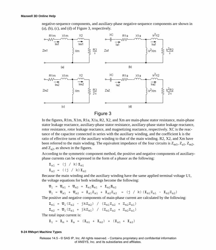
Maxwell 3D Online Help
negative-sequence components, and auxiliary-phase negative-sequence components are shown in (a), (b), (c), and (d) of Figure 3, respectively.
In the figures, R1m, X1m, R1a, X1a, R2, X2, and Xm are main-phase stator resistance, main-phase stator leakage reactance, auxiliary-phase stator resistance, auxiliary-phase stator leakage reactance, rotor resistance, rotor leakage reactance, and magnetizing reactance, respectively. XC is the reac-tance of the capacitor connected in series with the auxiliary winding, and the coefficient k is the ratio of effective turns of the auxiliary winding to that of the main winding. R2, X2, and Xm have been referred to the main winding. The equivalent impedance of the four circuits is Zm1, Za1, Zm2, and Za2, as shown in the figures.
According to the symmetric component method, the positive and negative components of auxiliary-phase currents can be expressed in the form of a phasor as the following:
Ia1 = (j / k)Im1 Ia2 = ((j / k)Im2
Because the main winding and the auxiliary winding have the same applied terminal voltage U1, the voltage equations for both windings become the following:
U1 = Um1 + Um2 = Im1Zm1 + Im2Zm2 U1 = Ua1 + Ua2 = Ia1Za1 + Ia2Za2 = (j / k)(Im1Za1 - Im2Za2)
The positive and negative components of main-phase current are calculated by the following:
Im1 = U1(Za2 - jkZm2) / (Zm1Za2 + Zm2Za1)
Im2 = U1(Za1 + jkZm1) / (Zm1Za2 + Zm2Za1)
The total input current is:
I1 = Im + Ia = (Im1 + Im2) + (Ia1 + Ia2)
Figure 3
9-24 RMxprt Machine Types
Release 14.5 - © SAS IP, Inc. All rights reserved. - Contains proprietary and confidential information of ANSYS, Inc. and its subsidiaries and affiliates.

Maxwell 3D Online Help
Based on these two components of main-phase current, all current components shown in Figure 3 can be obtained by simple computation.
Then the total input current is:
I1 = Im + Ia = (Im1 + Im2) + (Ia1 + Ia2)
The positive- and negative-sequence air-gap power can be computed in the following way:
Pm1 = 2 * Irm1^2 * R2 / s
Pm2 = 2 * Irm2^2 * R2 / (2 - s)
The total air-gap power is:
Pm = Pm1 - Pm2
Tm, T2, P2, P1, and eff are computed in the same way as for three-phase induction motors.
The power factor is derived from:
PF = P1 / (U1 * I1)
Defining a Single-Phase Induction MotorThe general procedure for structurally defining a single-phase induction motor is as follows:
1. Insert a single-phase induction motor design in an existing or newly created project.
2. Double-click the Machine entry in the project tree to define the general data.
3. Double-click the Machine-Stator entry in the project tree to define the stator geometry.
4. Double-click the Machine-Stator-Slot entry in the project tree to define the stator slot dimen-sions.
5. Double-click the Machine-Stator-Winding entry in the project tree to define the stator wind-ings and conductors.
6. Double-click the Machine-Rotor entry in the project tree to define the rotor geometry.
7. Double-click the Machine-Rotor-Slot entry in the project tree to define the rotor slot dimen-sions.
8. Double-click the Machine-Rotor-Winding entry in the project tree to define the rotor conduc-tor, ventage hole dimensions, and skew.
9. Double-click the Machine-Shaft entry in the project tree to define the magnetism of the shaft.
10. Right-click Analysis in the project tree, and click Add Solution Setup to define the solution data.
11. Choose File>Save to save the project.
12. Choose RMxprt>Analyze to analyze the design.
Once the design is analyzed, the model can be imported into the Maxwell 2D Modeler, or can be used to create a new Maxwell 2D project, and a new Maxwell 3D design.
Note When you place the cursor over an entry field in the data windows, a brief description of that field appears in the status bar at the bottom of the RMxprt window.
RMxprt Machine Types 9-25
Release 14.5 - © SAS IP, Inc. All rights reserved. - Contains proprietary and confidential information of ANSYS, Inc. and its subsidiaries and affiliates.
Maxwell 3D Online Help
Please refer to the A Capacitor-Run Single-Phase Induction Motor Problem application note, on the technical support page of the ANSYS web site, for a specific example of a single-phase induction motor problem.
Defining the General Data for a Single-Phase Induction Motor
Use the General Data Properties window to define the basic parameters of the induction motor, such as the number of poles, frictional loss, and operation mode.
To define the general data:
1. To open the General Data Properties window, double-click the Machine entry in the project tree on the desktop. (You can also enter values in the Properties section of the desktop without opening a separate window.)
2. Enter the number of poles for the machine in the Number of Poles field. This value is the total number of poles in the stator (or the number of pole pairs multiplied by two).
3. Select one of the following for the Rotor Position:
• Inner Rotor
• Outer Rotor
4. Enter the energy loss due to friction at the given speed in the Frictional Loss field.
5. Enter the wind loss due to air resistance measured at the reference speed in the Wind Loss field.
6. Enter the given speed in the Reference Speed field.
7. Select the Operation Mode:
a. Click the button.The Select Operation Mode window appears.
b. Select from one of the following:
c. Click OK to close the Select Operation Mode window and return to the Properties win-dow.
8. Enter values in the following capacitance, resistance, and switching speed fields:
C-Run Capacitance-run mode. The capacitor is in series with the auxiliary winding. In the Capacitor run mode, the capacitor will be designed (if the auto-design mode is selected) to minimize the backward magnetomotive force.
C-Start Capacitance-start mode. The auxiliary winding is in series with the capacitor and is disconnected when the rotor reaches the switching speed.
C-R&S Capacitance-run and start mode. Two capacitors are in series with the auxiliary winding; one for starting, one for running.
R-Start Resistor-start mode. The auxiliary winding is disconnected when the rotor reaches the switching speed.
Run Capacitance Available for C-Run, C-R&S
Run Resistance Available for C-Run, C-R&S
9-26 RMxprt Machine Types
Release 14.5 - © SAS IP, Inc. All rights reserved. - Contains proprietary and confidential information of ANSYS, Inc. and its subsidiaries and affiliates.

Maxwell 3D Online Help
9. If the start winding needs to be optimized, select the Objective Type from the following three options:
• (Tst/Ist)max. Accept the defaults. This is the ratio of the maximum starting torque to the starting current ratio.
• (Tst)max. Enter the given start current ratio. This is the maximum starting torque
• (Ist)min (minimum starting current). Enter the given start torque ratio.
10. Click OK to close the Properties window.
General Data for Single-Phase Induction Motors
To access the general data, double-click the Machine entry in the project tree.
The General Data Properties window for a three-phase induction motor contains the following fields:
Start Capacitance Available for C-Start, C-R&S
Start Resistance Available for C-Start, C-R&S
Switching Speed Available for C-Start, C-R&S, R-Start
Note The start-winding optimization goal is disabled for the C-Run operation mode.
In capacitor-run mode, the capacitor is designed to minimize the backward magnetomotive force. For other modes, if the auto-design function is active, the capacitor and the resistance are designed according to the start goal, selected from the following:
• The maximum value of (Starting Torque/Starting Current).
• The maximum starting torque.
• The minimum starting current.
Machine Type The machine type you selected when inserting a new RMxprt design (Single Phase Induction Motor).
Number of Poles The number of poles the machine contains.
Rotor Position Select whether the rotor is an Inner Rotor or Outer Rotor.
Frictional Loss The frictional energy loss (due to friction) measured at the reference speed.
Wind Loss The wind loss (due to air resistance) measured at the reference speed.
Reference Speed The given speed of reference.
Operation Mode Click the button to select from the following four modes: C-Run, C-Start, C-R&S, and R-Start.
Run Capacitance The capacitance of the run capacitor. Available for C-Run and C-R&S operation modes.
Run Resistance The resistance of the run capacitor. Available for C-Run and C-R&S operation modes. See Note below.
RMxprt Machine Types 9-27
Release 14.5 - © SAS IP, Inc. All rights reserved. - Contains proprietary and confidential information of ANSYS, Inc. and its subsidiaries and affiliates.

Maxwell 3D Online Help
Defining the Stator Data for a Single-Phase Induction MotorThe stator is the outer lamination stack where the three-phase windings reside. In the project tree, double-click Machine-Stator, Machine-Stator-Slot, and Machine-Stator-Winding to define the physical dimensions, slot data, wires, and conductors for the stator.
To define general stator data:
1. To open the Stator Data Properties window, double-click the Machine>Stator entry in the project tree on the desktop. (You can also enter values in the Properties section of the desktop without opening a separate window.)
2. Enter the Outer Diameter of the stator.
3. Enter the Inner Diameter of the stator.
4. Enter the length of the stator core in the Length field.
5. Enter the stacking factor for the stator core in the Stacking Factor field.
6. Select a Steel Type for the stator core:
a. Click the button for Steel Type.
Start Capacitance The resistance of the start capacitor. Available for C-Start and C-R&S operation modes.
Start Resistance The resistance of the start capacitor. Available for C-Start and C-R&S operation modes.
Switching Speed The switching speed of the capacitor or resistor. Available for C-Start, C-R&S, and R-Start operation modes.
Objective Type If the start winding needs to be optimized, select from the following three objective types: (Tst/Ist)max, (Tst)max, or (Ist)min.
• For (Tst/Ist) max, accept the defaults. This is the ratio of the maximum starting torque to the starting current ratio.
• For (Tst) max, enter the Given Start Current Ratio. This is the maximum starting torque.
• For (Ist) min (minimum starting current), enter the Given Start Torque Ratio.
The start-winding optimization goal is disabled for the C-Run operation mode.
Note When exporting the RMxprt model to Maxwell:
• If the value of the Run Resistance is zero in RMxprt, the value of the Run Resistance will be autocomputed in Maxwell to a value of 1% of the capacitor reactance.
• To neglect the Run Resistance in Maxwell, set the value to a small non-zero number in RMxprt.
9-28 RMxprt Machine Types
Release 14.5 - © SAS IP, Inc. All rights reserved. - Contains proprietary and confidential information of ANSYS, Inc. and its subsidiaries and affiliates.
Maxwell 3D Online Help
The Select Definition window appears.
b. Select a steel type from the list, or define a new steel type.
c. Click OK to close the Select Definition window and return to the Properties window.
7. Enter the Number of Slots in the stator.
8. Select the Slot Type:
a. Click the button for the Slot Type.The Select Slot Type window appears.
b. Select a slot type (available types include 1 through 4).
c. Click OK to close the Select Slot Type window and return to the Properties window.
9. Click OK to close the Properties window.
Stator Data for Single-Phase Induction Motors
To access the general stator data, double-click the Machine>Stator entry in the project tree.
The Stator Data Properties window contains the following fields:
Defining the Stator Slots for a Single-Phase Induction MotorUse the Stator1 window to define the physical dimensions of the stator slots.
To define the stator slots:
1. To open the Stator Slot Data Properties window, double-click the Machine-Stator-Slot entry in the project tree on the desktop. (You can also enter values in the Properties section of the desktop without opening a separate window.)
2. Optionally, to automatically design the dimensions of slots Hs2, Bs1, and Bs2, select the Auto Design check box.
3. Optionally, to design dimensions of slots Bs1 and Bs2 based on the stator tooth width, select the Parallel Tooth check box, and enter a value in the Tooth Width field.
Note When you place the mouse cursor over the slot type, a schematic of the selected type appears, displaying the slot dimension variables.
Outer Diameter The outer diameter of the stator core.
Inner Diameter The inner diameter of the stator core.
Length The length of the stator core.
Stacking Factor The stacking factor of the stator core.
Steel Type The steel type of the stator core. Click the button to open the Select Definition window.
Number of Slots The number of slots the stator core contains.
Slot Type The type of slots in the stator core. Click the button to open the Select Slot Type window.
RMxprt Machine Types 9-29
Release 14.5 - © SAS IP, Inc. All rights reserved. - Contains proprietary and confidential information of ANSYS, Inc. and its subsidiaries and affiliates.

Maxwell 3D Online Help
4. Enter the available slot dimensions.
5. Click OK to close the Properties window.
Stator Slot Data for Single-Phase Induction MotorsTo access the stator slot data, double-click the Machine-Stator-Slot entry in the project tree.
The Stator Slot Data Properties window contains the following fields:
Hs0 Always available.
Hs1 Always available.
Hs2 Available only when Auto Design is cleared. When Auto Design is selected, this slot dimension is determined automatically.
Bs0 Always available.
Bs1 Available only when Auto Design and Parallel Tooth are both cleared. When Auto Design is selected, this slot dimension is determined automatically. When Parallel Tooth is selected, this slot dimension is determined based on the value entered in the Tooth Width field.
Bs2 Available only when Auto Design and Parallel Tooth are both cleared. When Auto Design is selected, this slot dimension is determined automatically. When Parallel Tooth is selected, this slot dimension is determined based on the value entered in the Tooth Width field.
Rs Rs is added when the slot type is 3 or 4.
Parallel Branches The number of parallel branches in the series winding.
Number of Strands
The number of wires per conductor in the series winding (0 for auto-design).
Wire Wrap The thickness of the double-sided wire wrap (0 for auto-pickup from the wire library).
Wire Size The wire diameter (0 for auto-design).
Auto Design Select or clear this to enable or disable auto-design of slots Hs2, Bs1, and Bs2. When this check box is selected, only two other fields appear in the window: Hs0 and Bs0.
Parallel Tooth
Select this to design Bs1 and Bs2 based on the tooth width. When this check box is selected, the Bs1 and Bs2 fields are removed, and the Tooth Width field is added.
Tooth WidthThe tooth width for the parallel tooth, on which Bs1 and Bs2 are designed.
Hs0 A slot dimension (see the diagram shown in the modeling window when Machine-Stator-Slot is selected).
Hs1 A slot dimension (see the diagram shown in the modeling window when Machine-Stator-Slot is selected).
Hs2 A slot dimension (see the diagram shown in the modeling window when Machine-Stator-Slot is selected).
9-30 RMxprt Machine Types
Release 14.5 - © SAS IP, Inc. All rights reserved. - Contains proprietary and confidential information of ANSYS, Inc. and its subsidiaries and affiliates.
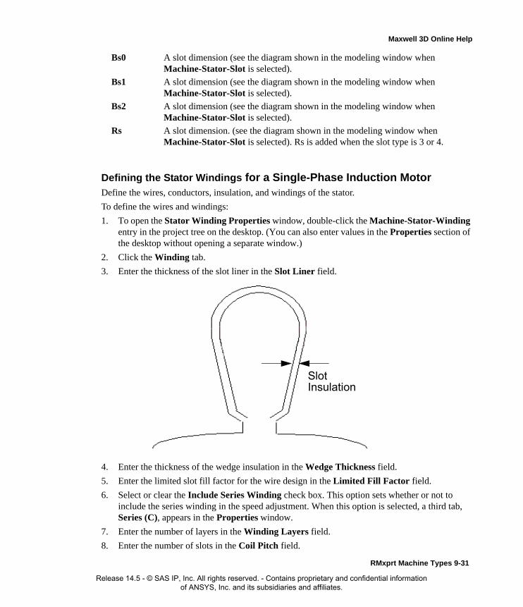
Maxwell 3D Online Help
Defining the Stator Windings for a Single-Phase Induction MotorDefine the wires, conductors, insulation, and windings of the stator.
To define the wires and windings:
1. To open the Stator Winding Properties window, double-click the Machine-Stator-Winding entry in the project tree on the desktop. (You can also enter values in the Properties section of the desktop without opening a separate window.)
2. Click the Winding tab.
3. Enter the thickness of the slot liner in the Slot Liner field.
4. Enter the thickness of the wedge insulation in the Wedge Thickness field.
5. Enter the limited slot fill factor for the wire design in the Limited Fill Factor field.
6. Select or clear the Include Series Winding check box. This option sets whether or not to include the series winding in the speed adjustment. When this option is selected, a third tab, Series (C), appears in the Properties window.
7. Enter the number of layers in the Winding Layers field.
8. Enter the number of slots in the Coil Pitch field.
Bs0 A slot dimension (see the diagram shown in the modeling window when Machine-Stator-Slot is selected).
Bs1 A slot dimension (see the diagram shown in the modeling window when Machine-Stator-Slot is selected).
Bs2 A slot dimension (see the diagram shown in the modeling window when Machine-Stator-Slot is selected).
Rs A slot dimension. (see the diagram shown in the modeling window when Machine-Stator-Slot is selected). Rs is added when the slot type is 3 or 4.
SlotInsulation
RMxprt Machine Types 9-31
Release 14.5 - © SAS IP, Inc. All rights reserved. - Contains proprietary and confidential information of ANSYS, Inc. and its subsidiaries and affiliates.

Maxwell 3D Online Help
9. Select a Winding Type:
a. Click the button for Winding Type.The Winding Type window appears.
b. Select from one of the following three types of winding:
• Whole Coiled
• Half Coiled
• Editor
When you place the mouse cursor over a winding button, an outline of the selected wind-ing appears. The following table describes the six types of windings that are possible (three for one-layer and three for two-layer):
Type Description
One-Layer Winding Editor
A user-defined one-layer winding arrangement. You need to set up the winding arrangement for each slot.
Whole Coiled
A one-layer whole-coiled winding:
123Slot
9-32 RMxprt Machine Types
Release 14.5 - © SAS IP, Inc. All rights reserved. - Contains proprietary and confidential information of ANSYS, Inc. and its subsidiaries and affiliates.

Maxwell 3D Online Help
Half Coiled
A one-layer concentric half-coiled winding:
Winding Editor
A user-defined two-layer winding arrangement. When you select 2 Winding layers, the Winding Editor is enabled, where you can specify a different winding arrangement for each slot.
Whole Coiled
A two-layer wave winding:
The phase belt for this winding configuration is equal to 360/2m, where m is the phase number.
123Slot
123Slot
RMxprt Machine Types 9-33
Release 14.5 - © SAS IP, Inc. All rights reserved. - Contains proprietary and confidential information of ANSYS, Inc. and its subsidiaries and affiliates.

Maxwell 3D Online Help
The following winding types are available:
Half Coiled
A two-layer half-coiled winding:
There is only one coil per phase per pair of poles.
Note For a two-layer winding, if you check Constant Pitch in the Winding Editor, only the top layer needs to be defined; the bottom layer will be determined according to the coil pitch.
A single-layer coil:
A 90-degree phase-belt two-layer coil.
1 2 3Slot
123Slot
9-34 RMxprt Machine Types
Release 14.5 - © SAS IP, Inc. All rights reserved. - Contains proprietary and confidential information of ANSYS, Inc. and its subsidiaries and affiliates.

Maxwell 3D Online Help
The available winding types vary with the slot type that is selected.
c. Once you have clicked a button to select a winding, click OK to close the Winding Type
A first-class sinusoidal coil. The Conductors per Layer field defines the maximum number of conductors in the slot. The software will determine the winding distribution in the slots to get the sinusoidal current distribution:
A second-class sinusoidal coil. The Conductors per Layer field defines the maximum number of conductors in the slot. The software will determine the winding distribution in the slots to get the sinusoidal current distribution.
A first-class concentric coil:
You must define the distribution of conductors per slot.
A second-class concentric coil:
You must define the distribution of conductors per slot.
123Slot
123Slot
RMxprt Machine Types 9-35
Release 14.5 - © SAS IP, Inc. All rights reserved. - Contains proprietary and confidential information of ANSYS, Inc. and its subsidiaries and affiliates.

Maxwell 3D Online Help
window and return to the Properties window.
10. Click the Main (A) tab.
11. Enter the end length adjustment of the main stator coil in the End Adjustment field. The end adjustment is the distance one end of the conductor extends vertically beyond the end of the stator.
12. Enter the number of conductors per layer of main winding in the Conductors per Layer field.
13. Enter the number of parallel branches in the main stator winding in the Parallel Branches field.
14. Enter the number of wires per conductor in the Number of Strands field. Enter 0 to have RMxprt auto-design the value.
15. Enter the thickness of the double-sided wire wrap in the Wire Wrap field. Enter 0 to automat-ically obtain this value from the wire library.
16. Select the Wire Size:
EndAdjustment
StatorCoil
End of Stator
Insulation
Conductor
y
Wire Wrap = 2*y
9-36 RMxprt Machine Types
Release 14.5 - © SAS IP, Inc. All rights reserved. - Contains proprietary and confidential information of ANSYS, Inc. and its subsidiaries and affiliates.

Maxwell 3D Online Help
a. Click the button for Wire Size.The Wire Size window appears.
b. Select a value from the Wire Diameter pull-down list.
c. Select a wire gauge from the Gauge pull-down menu. You can select from the following options:
The gauge number is based on AWG settings. You can create your own wire table using Machine>Wire, and then you can select this wire table using the Tools>Options>Machine Options command.
d. When you are done setting the wire size, click OK to close the Wire Size window and return to the Properties window.
17. Click the Aux (B) tab.
18. Enter the end length adjustment of the auxiliary stator coil in the End Adjustment field.
19. Enter the number of conductors per layer of auxiliary winding in the Conductors per Layer field.
20. Enter the number of parallel branches in the auxiliary stator winding in the Parallel Branches field.
21. Enter the number of wires per conductor in the Number of Strands field. Enter 0 to have RMxprt auto-design the value.
22. WIRE WRAP
23. WIRE SIZE
24. Click the Series (C) tab. (This tab only appears when Include Series Winding is selected on the Winding tab.)
25. Enter the end length adjustment of the series winding in the End Adjustment field.
26. Enter the number of parallel branches in the series stator winding in the Parallel Branches field.
27. Enter the number of wires per conductor in the Number of Strands field. Enter 0 to have RMxprt auto-design the value.
<number>You can select a specific gauge number. When you select a gauge number, the Wire Diameter field is automatically updated.
USERThis option allows you to manually enter the Wire Diameter. This is useful when you want to enter a diameter that does not correspond to a particular wire gauge.
AUTO
This option sets the Wire Diameter to zero, and RMxprt automatically calculates the optimal value. The diameter information is then written to the output file when you analyze the design.
MIXED
This option allows you to define a conductor that is made of different size wires. For example, a single conductor may consist of 5 wires, 3 wires with a diameter of 0.21mm and 2 with a diameter of 0.13mm.
RMxprt Machine Types 9-37
Release 14.5 - © SAS IP, Inc. All rights reserved. - Contains proprietary and confidential information of ANSYS, Inc. and its subsidiaries and affiliates.

Maxwell 3D Online Help
28. Enter the thickness of the double-sided wire wrap in the Wire Wrap field. Enter 0 to automat-
ically obtain this value from the wire library.
29. Select the Wire Size:
a. Click the button for Wire Size.The Wire Size window appears.
b. Select a value from the Wire Diameter pull-down list.
c. Select a wire gauge from the Gauge pull-down menu. You can select from the following options:
The gauge number is based on AWG settings. You can create your own wire table using Machine>Wire, and then you can select this wire table using the Tools>Options>Machine Options command.
d. When you are done setting the wire size, click OK to close the Wire Size window and return to the Properties window.
30. Click OK to close the Properties window.
Stator Winding Data for Single-Phase Induction MotorsTo access the stator winding data, double-click the Machine-Stator-Winding entry in the project tree.
<number>You can select a specific gauge number. When you select a gauge number, the Wire Diameter field is automatically updated.
USERThis option allows you to manually enter the Wire Diameter. This is useful when you want to enter a diameter that does not correspond to a particular wire gauge.
AUTO
This option sets the Wire Diameter to zero, and RMxprt automatically calculates the optimal value. The diameter information is then written to the output file when you analyze the design.
MIXED
This option allows you to define a conductor that is made of different size wires. For example, a single conductor may consist of 5 wires, 3 wires with a diameter of 0.21mm and 2 with a diameter of 0.13mm.
Insulation
Conductor
y
Wire Wrap = 2*y
9-38 RMxprt Machine Types
Release 14.5 - © SAS IP, Inc. All rights reserved. - Contains proprietary and confidential information of ANSYS, Inc. and its subsidiaries and affiliates.

Maxwell 3D Online Help
The Stator Winding Data Properties window contains the following fields:
Winding tabSlot Liner The thickness of the slot liner.
Wedge Thickness The thickness of the wedge insulation
Limited Fill Factor
The limited slot fill factor for the wire design.
Include Series Winding
Select or clear to specify whether or not to include the series winding in the speed adjustment. When this option is selected, a third tab, Series (C), appears in the Properties window.
Winding Layers The number of winding layers.
Coil Pitch The coil pitch measured in number of slots.
Winding Type The type of stator winding for the main phase. Click the button to open the Winding Type window and choose from Whole Coiled, Half Coiled, and Editor.
Main (A) End Adjustment The end length adjustment of the stator coils.
Conductors per Layer
The number of conductors per layer in the main winding.
Parallel Branches The number of parallel branches in the main stator winding.
Number of Strands
The number of wires per conductor (0 for auto-design).
Wire Wrap The thickness of the double-sided wire wrap (0 for auto-pickup from the wire library).
Wire Size The wire diameter (0 for auto-design).
Aux (B) End Adjustment The end length adjustment of the auxiliary winding.
Conductors per Layer
The number of conductors per layer in the auxiliary winding.
Parallel Branches The number of parallel branches in the auxiliary stator winding.
Number of Strands
The number of wires per conductor in the auxiliary winding (0 for auto-design).
Wire Wrap The thickness of the double-sided wire wrap (0 for auto-pickup from the wire library).
Wire Size The wire diameter (0 for auto-design).
Series (C) This tab appears when Include Series Winding is selected on the Winding tab.
End Adjustment The end length adjustment of the series winding.
Parallel Branches The number of parallel branches in the series winding.
RMxprt Machine Types 9-39
Release 14.5 - © SAS IP, Inc. All rights reserved. - Contains proprietary and confidential information of ANSYS, Inc. and its subsidiaries and affiliates.

Maxwell 3D Online Help
Winding Editor for a SIngle-Phase Induction Motor
For a single-phase induction motor, you may want to specify a different number of conductors for each stator slot. The Winding Editor makes this possible by enabling you to specify the number of turns for each coil.
To specify the number of turns for each coil:
1. Click Machine>Winding>Edit Layout.The Winding Editor window appears.
2. In the table in the upper left, set which phase you want for each coil and which slot is the “in” and “out” slot for the current in each coil.
3. If you are working on a quarter or half model, you may want to specify a multiplier by clicking the Periodic Multiplier check box and specifying a value.
4. Select or deselect the Constant Turns or Constant Pitch check boxes, depending on whether you want to be able to change these setting in the table above. When these options are selected, you cannot change the turns or pitch.
5. When you are satisfied with the coil settings, click OK to close the Winding Editor window.
Defining Different Size Wires for a Single-Phase Induction MotorUse the Gauge option if you have a conductor that is made up different size wires.
To define different size wires:
1. In the Wire Size window, select MIXED from the Gauge pull-down menu.
2. Select either Round or Rectangular as the Wire Type.
3. Enter the appropriate wire data in the table:
• For a round wire:
• Enter the Diameter in the table.
• Enter a Number in the table to specify how many of the conductor’s wires have this diameter.
• For a rectangular wire:
• Enter the Width of the wire in the table.
• Enter the Thickness of the wire in the table.
• Enter the Fillet value in the table.
• Enter a Number in the table to specify how many of the conductor’s wires have this data.
Number of Strands
The number of wires per conductor in the series winding (0 for auto-design).
Wire Wrap The thickness of the double-sided wire wrap (0 for auto-pickup from the wire library).
Wire Size The wire diameter (0 for auto-design).
9-40 RMxprt Machine Types
Release 14.5 - © SAS IP, Inc. All rights reserved. - Contains proprietary and confidential information of ANSYS, Inc. and its subsidiaries and affiliates.

Maxwell 3D Online Help
4. Choose Add to add the new wire data.
5. Repeat steps 3 and 4 for each size wire you want to add.
6. When you are finished defining the wires, click OK to close the Wire Size window.
Defining the Rotor Data for a Single-Phase Induction Motor
The rotor consists of copper bars in which current is induced from the stator windings. The rotor rotates at a slightly slower speed than the stator electromagnetic field. In the project tree, double-click Machine>Rotor, Machine-Rotor-Slot, and Machine-Rotor-Winding to define the physical dimensions, slot data, wires, and conductors for the rotor.
To define the general rotor data:
1. To open the Rotor Properties window, double-click the Machine>Rotor entry in the project tree on the desktop. (You can also enter values in the Properties section of the desktop without opening a separate window.)
2. Enter the stacking factor for the rotor core in the Stacking Factor field.
3. Enter the Number of Slots in the rotor.
4. Select the Slot Type:
a. Click the button for the Slot Type.The Select Slot Type window appears.
b. Select a slot type (available types include 1 through 4).
c. Click OK to close the Select Slot Type window and return to the Properties window.
5. Enter the outer diameter of the rotor in the Outer Diameter field.
6. Enter the inner diameter of the rotor in the Inner Diameter field.
7. Enter the length of the rotor core in the Length field.
8. Select a Steel Type for the rotor core:
a. Click the button for Steel Type.The Select Definition window appears.
b. Select a steel type from the list, or define a new steel type.
c. Click OK to close the Select Definition window and return to the Properties window.
9. Enter the Skew Width, measured in rotor slot pitch. This value defines by how much the rotor bars are skewed.
Note For example, if one conductor is made up of 5 wires, and 3 of those wires have a diameter of 0.21mm, and the other 2 have a diameter of 0.13mm, then the mixed wire size table will have two lines. The first line will list Diameter = 0.21 and Number = 3. The second line will list Diameter = 0.13 and Number = 2. An equivalent wire diameter is displayed as Wire Size value in the Winding tab in the Properties window.
Note When you place the mouse cursor over the slot type, a schematic of the selected type appears, displaying the slot dimension variables.
RMxprt Machine Types 9-41
Release 14.5 - © SAS IP, Inc. All rights reserved. - Contains proprietary and confidential information of ANSYS, Inc. and its subsidiaries and affiliates.

Maxwell 3D Online Help
10. Optionally, select Cast Rotor to allow the conductor to fill all the space available in the slot. Otherwise, RMxprt assumes the slot wedge that fixes the bars is filled with insulator material in a 3D/3D geometry model.
11. Click OK to close the Properties window.
Rotor Data for Single-Phase Induction Motors
To access the general rotor data, double-click the Machine>Rotor entry in the project tree.
The Rotor Data Properties window contains the following fields:
Defining the Rotor Slots for Single-Phase Induction MotorsTo define the rotor’s slots:
1. To open the Rotor Slot Properties window, double-click the Machine-Rotor-Slot entry in the project tree on the desktop. (You can also enter values in the Properties section of the desktop without opening a separate window.)
2. Enter the slot dimensions in the following fields: Hs0, Hs01, Hs2, Bs0, Bs1, Bs2, Rs.
3. Click OK to close the Properties window.
Rotor Slot Data for Single-Phase Induction MotorsTo access the rotor slot data, double-click the Machine-Rotor-Slot entry in the project tree.
The Rotor Slot Data Properties window contains the following fields:
Stacking Factor The stacking factor of the rotor core.
Number of Slots The number of slots the rotor core contains.
Slot Type The type of slots in the rotor core. Click the button to open the Select Slot Type window.
Outer Diameter The outer diameter of the rotor core.
Inner Diameter The inner diameter of the rotor core.
Length The length of the rotor core.
Steel Type The steel type of the rotor core. Click the button to open the Select Definition window.
Skew Width The skew width measured in slot number.
Cast Rotor Select or clear this to specify whether the rotor squirrel-cage winding is cast or not.
Hs0 A slot dimension (see the diagram shown in the modeling window when Machine-Rotor-Slot is selected).
Hs01 A slot dimension (see the diagram shown in the modeling window when Machine-Rotor-Slot is selected).
Hs1 A slot dimension (see the diagram shown in the modeling window when Machine-Rotor-Slot is selected).
Hs2 A slot dimension (see the diagram shown in the modeling window when Machine-Rotor-Slot is selected).
9-42 RMxprt Machine Types
Release 14.5 - © SAS IP, Inc. All rights reserved. - Contains proprietary and confidential information of ANSYS, Inc. and its subsidiaries and affiliates.
Maxwell 3D Online Help
Defining the Rotor Windings for Single-Phase Induction MotorsTo define the rotor windings:
1. To open the Rotor Winding Properties window, double-click the Machine-Rotor-Winding entry in the project tree on the desktop. (You can also enter values in the Properties section of the desktop without opening a separate window.)
2. Select a Bar Conductor Type for the rotor winding bar:
a. Click the button for Bar Conductor Type.The Select Definition window appears.
b. Select a conductor type from the list, or define a new conductor type.
c. Click OK to close the Select Definition window and return to the Properties window.
3. Enter the length of the gap between the end ring and the iron core in the End Length field. This field specifies the value for only one end of the gap, not both.
4. Enter the end ring dimension in the axial direction in the End-Ring Width field. The end ring connects the bars of the rotor to one another.
5. Enter the end ring dimension in the radius direction in the End-Ring Height field. The end ring’s height covers at least the cross section of the rotor conductor.
6. Select an End Ring Conductor Type for the rotor winding end ring:
a. Click the button for End Ring Conductor Type.The Select Definition window appears.
b. Select a conductor type from the list, or define a new conductor type.
c. Click OK to close the Select Definition window and return to the Properties window.
7. Click OK to close the Properties window.
Rotor Winding Data for Single-Phase Induction Motors
To access the rotor winding data, double-click the Machine-Rotor-Winding entry in the project tree.
Bs0 A slot dimension (see the diagram shown in the modeling window when Machine-Rotor-Slot is selected).
Bs1 A slot dimension (see the diagram shown in the modeling window when Machine-Rotor-Slot is selected).
Bs2 A slot dimension (see the diagram shown in the modeling window when Machine-Rotor-Slot is selected).
Rs A slot dimension. (see the diagram shown in the modeling window when Machine-Stator-Slot is selected). Rs is added when the slot type is 3 or 4.
RMxprt Machine Types 9-43
Release 14.5 - © SAS IP, Inc. All rights reserved. - Contains proprietary and confidential information of ANSYS, Inc. and its subsidiaries and affiliates.

Maxwell 3D Online Help
The Rotor Winding Data Properties window contains the following fields:
Adding or Removing a Vent from a Single-Phase Induction MotorBy option, you can add a vent to a single-phase induction motor. To add a vent:.
1. Select the rotor icon in the project tree.
2. Right-click to display the pop-up menu and select Insert Vent.
The vent icon appears in the project tree under the rotor.
To remove a vent from a rotor in a three-phase induction motor.
1. Select the rotor icon in the project tree.
2. Right-click to display the pop-up menu and select Remove Vent.
The vent icon disappears in the project tree under the rotor.
The Vent data for the stator includes the following fields.
Defining the Shaft Data for a Single-Phase Induction Motor
To define the shaft:
1. To open the Shaft Data Properties window, double-click the Machine>Shaft entry in the project tree on the desktop. (You can also enter values in the Properties section of the desktop without opening a separate window.)
2. Select or clear the Magnetic Shaft check box to specify whether or not the shaft is to be made of magnetic material.
3. Click OK to close the Properties window.
Shaft Data for Single-Phase Induction Motors
To access the shaft data, double-click the Machine>Shaft entry in the project tree.
Bar Conductor Type
The type of bar conductor used in the winding. Click the button to open the Select Definition window.
End Length The length of the single-side end of the extended bar.
End Ring Width The width of one side of the end rings in the axial direction.
End Ring Height The height of the end rings in the radian direction.
End Ring Conductor Type
The type of end ring conductor used in the winding. Click the button to open the Select Definition window.
Holes per row Number of axial vent holes per row.
Inner hole diameter Diameter of vent holes in inner row.
Outer hole diameter Diameter of vent holes in outer row.
Inner hole location Center to center diameter of inner hole vents
Outer hole location Center to center diameter of outer hole vents.
9-44 RMxprt Machine Types
Release 14.5 - © SAS IP, Inc. All rights reserved. - Contains proprietary and confidential information of ANSYS, Inc. and its subsidiaries and affiliates.

Maxwell 3D Online Help
The Shaft Data Properties window contains the following fields:
Setting Up Analysis Parameters for a Single-Phase Induction MotorTo define the solution data:
1. To open the Solution Setup window, right-click Analysis in the project tree, and click Add Solution Setup.
2. Click the General tab. The Operation Type is automatically set to Motor for this machine type.
3. Select the Load Type used in the motor from the following options:
1. Enter the output power developed at the shaft of the motor in the Rated Output Power field.
2. Enter the RMS line-to-line voltage in the Rated Voltage field.
3. Enter the desired output speed of the motor at the load point in the Rated Speed field.
4. Enter the temperature at which the system functions in the Operating Temperature field.
5. Click the Single-Phase Induction Motor tab.
6. Enter the electrical line frequency in the Frequency field, and select the units.
7. Click OK to close the Solution Setup window.
Related Topics:
Solution Data for Single-Phase Induction Motors
Solution Data for Single-Phase Induction MotorsTo access the solution data, right-click Analysis in the project tree, and click Add Solution Setup.
Magnetic Shaft Select or clear this check box to indicate whether or not the shaft is made of magnetic material.
Const Speed The speed remains constant in the motor.
Const Power The output power remains constant in the motor.
Const Torque The torque remains constant regardless of the speed. In this case, Tload = Trated, given by the output power divided by the given rated speed.
Linear Torque The torque increases linearly with speed. In this case, Tload = Trated * (n/nrated) where Trated is given by the output power divided by the given rated speed.
Fan Load The load varies nonlinearly with speed. In this case, Tload = Trated * (n/nrated)2 where Trated is given by the output power divided by the given rated speed.
RMxprt Machine Types 9-45
Release 14.5 - © SAS IP, Inc. All rights reserved. - Contains proprietary and confidential information of ANSYS, Inc. and its subsidiaries and affiliates.

Maxwell 3D Online Help
The Solution Setup window contains the following fields:
Related Topics:
Setting Up Analysis Parameters for a Single-Phase Induction Motor
Operation Type On the General tab. The operation type is automatically set to Motor for this machine type.
Load Type On the General tab. Select from Const Speed, Const Power, Const Torque, Linear Torque, and Fan Load. The default is Const Power.
Rated Output Power
On the General tab. Type a value for the rated output voltage, and select the units.
Rated Voltage On the General tab. Type a value for the rated voltage, and select the units.
Rated Speed On the General tab. Type a value for the rated speed, and select the units.
Operating Temperature
On the General tab. Type a value for the operating temperature, and select the units.
Frequency On the Single-Phase Induction Motor tab. Type a value for the frequency, and select the units.
9-46 RMxprt Machine Types
Release 14.5 - © SAS IP, Inc. All rights reserved. - Contains proprietary and confidential information of ANSYS, Inc. and its subsidiaries and affiliates.

Maxwell 3D Online Help
Adjust-Speed Synchronous MachinesAfter you have selected Adjust-Speed Synchronous Machines as your model type, you need to define the following:
• General data, such as the voltage, speed, and circuit type of the model.
• Circuit data, such as trigger pulse width, transistor drop, and control circuit information.
• Stator data, such as the diameter, slot dimensions, and skew width of the stator.
• Stator Winding
• Rotor pole data, such as the associated permanent-magnet dimensions, air gap, and stacking factor.
• Solution data, such as rated output voltage and frequency.
Analysis Approach Data for Adjust-Speed Synchronous MachinesIn adjustable-speed permanent-magnet synchronous machines, the rotor speed is controlled by adjusting the frequency of the input voltage. Unlike standard brushless permanent-magnet DC motors, this type of machine does not utilize position sensors.
Permanent magnets are mounted on the rotor of a permanent-magnet synchronous machine, which could be either inner or outer rotor type. The poly-phase armature winding is embedded in the sta-tor, whose number of poles is the same as that of the rotor. The machine can operate as a generator or as a motor. When the machine operates as a motor, the stator poly-phase winding can be fed either by a sinusoidal AC source or by a DC source via a DC to AC inverter. When the machine operates as a generator, the stator poly-phase winding supplies an AC source for electric loads.
RMxprt Machine Types 9-47
Release 14.5 - © SAS IP, Inc. All rights reserved. - Contains proprietary and confidential information of ANSYS, Inc. and its subsidiaries and affiliates.

Maxwell 3D Online Help
Stator Winding Connected to a Sinusoidal AC Source
In this case, the performance of the machine can be analyzed in the frequency domain based on the phasor diagrams, as shown in Figure 6.1 for the generators and Figure 6.2 for the motors.
In the figures, R1 and X1 are the resistance and the leakage reactance of the armature winding, Xad and Xaq are the d-axis armature reactance and the q-axis armature reactance, respectively. In the
O
I
I d
I q
U
IR1
jI Xaq
jI q Xaq
E 0 jI d Xad
M
N
jI X1
Figure 6.1 The phasor diagram for generators
O
I
I d I q
U
IR1
jI Xaq
jI q Xaq E0
jI d Xad
M jI X1
N
Figure 6.2 The phasor diagram for motors
9-48 RMxprt Machine Types
Release 14.5 - © SAS IP, Inc. All rights reserved. - Contains proprietary and confidential information of ANSYS, Inc. and its subsidiaries and affiliates.
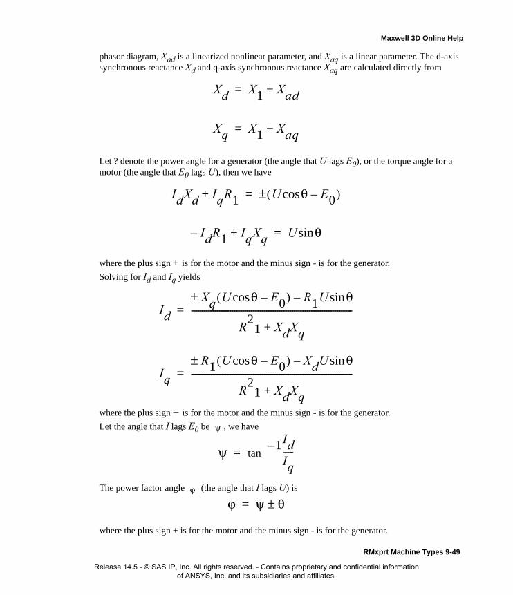
Maxwell 3D Online Help
phasor diagram, Xad is a linearized nonlinear parameter, and Xaq is a linear parameter. The d-axis synchronous reactance Xd and q-axis synchronous reactance Xaq are calculated directly from
Let ? denote the power angle for a generator (the angle that U lags E0), or the torque angle for a motor (the angle that E0 lags U), then we have
where the plus sign + is for the motor and the minus sign - is for the generator.
Solving for Id and Iq yields
where the plus sign + is for the motor and the minus sign - is for the generator.
Let the angle that I lags E0 be , we have
The power factor angle (the angle that I lags U) is
where the plus sign + is for the motor and the minus sign - is for the generator.
Xd X1 Xad+=
Xq X1 Xaq+=
IdXd IqR1+ U θcos E0–( )±=
IdR1– IqXq+ U θsin=
Id
Xq U θcos E0–( )± R1U θsin–
R2
1 XdXq+---------------------------------------------------------------------------=
Iq
R1 U θcos E0–( )± XdU θsin–
R2
1 XdXq+---------------------------------------------------------------------------=
ψ
ψ tan1– Id
Iq-----=
ϕ
ϕ ψ θ±=
RMxprt Machine Types 9-49
Release 14.5 - © SAS IP, Inc. All rights reserved. - Contains proprietary and confidential information of ANSYS, Inc. and its subsidiaries and affiliates.
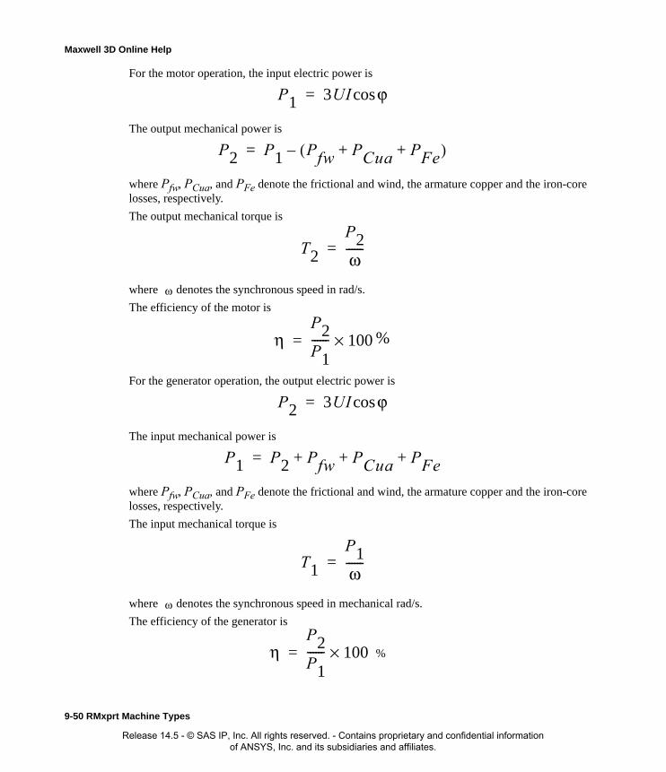
Maxwell 3D Online Help
For the motor operation, the input electric power is
The output mechanical power is
where Pfw, PCua, and PFe denote the frictional and wind, the armature copper and the iron-core losses, respectively.
The output mechanical torque is
where denotes the synchronous speed in rad/s.
The efficiency of the motor is
For the generator operation, the output electric power is
The input mechanical power is
where Pfw, PCua, and PFe denote the frictional and wind, the armature copper and the iron-core losses, respectively.
The input mechanical torque is
where denotes the synchronous speed in mechanical rad/s.
The efficiency of the generator is
P1 3UI ϕcos=
P2 P1 Pfw PCua PFe+ +( )–=
T2
P2ω------=
ω
ηP2P1------ 100×= %
P2 3UI ϕcos=
P1 P2 Pfw PCua PFe+ ++=
T1
P1ω------=
ω
ηP2P1------ 100×= %
9-50 RMxprt Machine Types
Release 14.5 - © SAS IP, Inc. All rights reserved. - Contains proprietary and confidential information of ANSYS, Inc. and its subsidiaries and affiliates.

Maxwell 3D Online Help
Stator Winding Fed by a DC to AC Inverter
In this case, this adjustable-speed synchronous machine (ASSM) operates as a motor, and the anal-ysis approach is similar to that of a brushless DC (BLDC) motor. The stator poly-phase armature winding is connected to a DC power supply through a DC to AC inverter to produce the rotational magnetic field in the air-gap. The main difference between ASSM and BLDC motor is: in BLDC motor, trigger time exactly depends on the rotor position; but in ASSM, the trigger time is inde-pendent of the rotor position. If the mechanical load of a BLDC motor increases, the rotor speed and the induced voltage decreases, causing the armature current and torque increase to balance the increased mechanical load. However, for an ASSM, if the mechanical load increases, the rotor speed decreases temporarily, which causes the torque angle (the same as lead angle of trigger for a BLDC motor) increase and then torque increase to retain the synchronous speed.
Therefore, the speed of a BLDC motor varies with input voltage and mechanical load, while the speed of an ASSM does not. The speed of an ASSM can be changed by adjusting the frequency of the controlling signal, which explains why it is called Adjustable-Speed Permanent-Magnet Syn-chronous Machine.
Using the time-domain mathematical model to analyze the characteristics of the electric machine, Park's voltage equation in the matrix form is as follows
where R1 is the armature winding resistance, Ld, Lq and L0 are the d-, the q- and the 0-axis induc-tances respectively, is the revolution speed in electric radians per second, the differential opera-tor is
The coordinate transformation equations for the terminal voltage, the induced emf and the armature winding current are
vd
vq
v0
ed
eq
e0
–
R1 Ldρ+ Lqωe– 0
Ldωe– R1 Lqρ+ 0
0 0 R1 L0ρ+
id
iq
i0
⋅=
ωe
ρtd
d=
vd
vq
v0
CT
va
vb=
ed
eq
e0
CT
ea
eb=
ia
ibC
id
iq
i0
=
RMxprt Machine Types 9-51
Release 14.5 - © SAS IP, Inc. All rights reserved. - Contains proprietary and confidential information of ANSYS, Inc. and its subsidiaries and affiliates.

Maxwell 3D Online Help
The transformation matrices for the two-, the three- and the four-phase systems are C2, C3 and C4, respectively, as follows
where
The input electric power is obtained from the voltage and the current as:
The output mechanical power is:
C2θcos θsin 0
θsin θcos 0=
C323---
θcos θsin1
2-------
θ α–( )cos θ α–( )sin1
2-------
θ 2α–( )cos θ 2α–( )sin1
2-------
=
C4
θcos θsin 0
θsin θcos– 0
θcos– θsin– 0
θsin– θcos 0
=
α 23---π=
p11T--- vdid vqiq v0i0+ +( ) td
0
T
=
P2 P1 Pfw PCua PFe+ +( )–=
9-52 RMxprt Machine Types
Release 14.5 - © SAS IP, Inc. All rights reserved. - Contains proprietary and confidential information of ANSYS, Inc. and its subsidiaries and affiliates.

Maxwell 3D Online Help
where Pfw, PCua, Pt and PFe denote the frictional and wind, the armature copper, the switching and the iron-core losses, respectively.
The output mechanical torque is
where denotes the revolution speed in mechanical radians per second.
The efficiency of the electric machine is
Defining an Adjustable-Speed Synchronous MachineThe general procedure for defining a adjust-speed synchronous machine is as follows:
1. Insert the adjust-speed synchronous machine into a new or existing project.
2. Double-click the Machine entry in the project tree to define the general data.
3. Double-click the Machine>Circuit entry in the project tree to define the control circuit.
4. Double-click the Machine>Stator entry in the project tree to define the stator geometry.
5. Double-click the Machine-Stator-Slot entry in the project tree to define the stator slot dimen-sions.
6. Double-click the Machine-Stator-Winding entry in the project tree to define the stator wind-ings and conductors.
7. Double-click the Machine-Rotor entry in the project tree to define the rotor geometry.
8. Double-click the Machine-Rotor-Pole entry in the project tree to define the pole, embrace, offset, and air gap data for the rotor pole.
9. Double-click the Machine>Shaft entry in the project tree to define the magnetism of the shaft.
10. Right-click Analysis in the project tree, and click Add Solution Setup to define the solution data.
11. Choose File>Save to save the project.
12. Choose RMxprt>Analyze to analyze the design.
Once analyzed, the model can be viewed in the Maxwell 2D Modeler, or it can be used to create a new Maxwell 2D project, and a new Maxwell 3D design.
Note When you place the cursor over an entry field in the data windows, a brief description of that field appears in the status bar at the bottom of the RMxprt window.
T2
P2ω------=
ω
ηP2P1------ 100×= %
RMxprt Machine Types 9-53
Release 14.5 - © SAS IP, Inc. All rights reserved. - Contains proprietary and confidential information of ANSYS, Inc. and its subsidiaries and affiliates.

Maxwell 3D Online Help
Defining the General Data for an Adjust-Speed Synchronous Machine
Use the General window to define the basic parameters of the motor, such as the motor’s rated out-put power, rated voltage, losses, and circuit types.
To define the general data:
1. To open the General Data Properties window, double-click the Machine entry in the project tree on the desktop. (You can also enter values in the Properties section of the desktop without opening a separate window.)
2. Enter the number of poles for the machine in the Number of Poles field. This value is the total number of poles in the stator (or the number of pole pairs multiplied by two).
3. Enter the energy loss due to friction at the given speed in the Frictional Loss field.
4. Enter the wind loss due to air resistance measured at the reference speed in the Windage Loss field.
5. Enter the given speed in the Reference Speed field.
6. Select one of the following from the Control Type pull-down list:
• DC: Switched DC voltage at the given input frequency.
• PWM: Pulse width modulation. When you select this source type, you must enter the fol-lowing values in the Circuit Data Properties window: Modulation Index (the ratio of the sine wave amplitude to the triangular amplitude) and Carrier Frequency Times (the ratio of the triangular frequency to the sine wave frequency).
• AC: An AC excitation.
7. Select a Circuit Type from the following types:
The circuit types are based on industry standards. By default, type Y3, a three-phase, six-status circuit, is selected as the circuit type.
8. Click OK to close the Properties window.
General Data for Adjust-Speed Synchronous Machines
To access the general data, double-click the Machine entry in the project tree.
Y3 Y-connected, three-phase.
L3 Loop-type, three-phase.
S3 Star-type, three-phase.
C2 Cross-type, two-phase.
L4 Loop-type, four-phase.
S4 Star-type, four-phase.
Note When you place the mouse cursor over a circuit type, an outline schematic of the circuit appears.
9-54 RMxprt Machine Types
Release 14.5 - © SAS IP, Inc. All rights reserved. - Contains proprietary and confidential information of ANSYS, Inc. and its subsidiaries and affiliates.
Maxwell 3D Online Help
The General Data Properties window for a three-phase induction motor contains the following fields:
Defining the Circuit Data for an Adjust-Speed Synchronous MachineUse the Circuit Data Properties window to define the circuit properties for an adjustable-speed synchronous machine.
1. To open the Circuit Data Properties window, double-click the Machine>Circuit entry in the project tree on the desktop. (You can also enter values in the Properties section of the desktop without opening a separate window.)
2. If you selected DC as the Control Type, enter the period from on-status to off-status of a tran-sistor, in electrical degrees, in the Trigger Pulse Width field.
3. Enter the voltage drop across one transistor when the transistor is turned on in the Transistor Drop field. Refer to the figures of the different circuit types in step 2.
4. Enter the voltage drop of one diode in the discharge loop in the Diode Drop field. If you selected a star-type circuit (S3 or S4) as the Circuit Type, enter the total discharge voltage in this field.
5. If you selected PWM as the Control Type, then enter values in the following two fields:
• Modulation Index: The ratio of the sine-wave amplitude to the triangular amplitude.
Machine Type The machine type you selected when inserting a new RMxprt design (Adjust-Speed Synchronous Machine).
Number of Poles The number of poles the machine contains.
Rotor Position Select whether the rotor is an Inner Rotor or Outer Rotor.
Frictional Loss The frictional energy loss (due to friction) measured at the reference speed.
Windage Loss The windage loss (due to air resistance) measured at the reference speed.
Reference Speed The given speed of reference.
Control Type The way the circuit is controlled. Select from DC, PWM (pulse-width modulation), or AC.
Circuit Type The drive circuit type. Click the button to open the Circuit Type window and select from the following six types:
• Y3: Y-Type, 3-Phase
• L3: Loop-Type, 3-Phase
• S3: Star-Type, 3-Phase
• C2: Cross-Type, 2-Phase
• L4: Loop-Type, 4-Phase
• S4: Star-Type, 4-Phase
Note No circuit data properties exist when AC is selected as the Control Type.
RMxprt Machine Types 9-55
Release 14.5 - © SAS IP, Inc. All rights reserved. - Contains proprietary and confidential information of ANSYS, Inc. and its subsidiaries and affiliates.
Maxwell 3D Online Help
(PWM circuits only.)
• Carrier Frequency Times: The ratio of the triangular frequency to the sine-wave fre-quency. (PWM circuits only.)
6. Click OK to close the Properties window.
Circuit Data for Adjust-Speed Synchronous Machines
To access the Circuit Data Properties window, double-click the Machine>Circuit entry in the project tree. No circuit data properties exist when AC is selected as the Control Type.
Defining the Stator Data for an Adjust-Speed Synchronous MachineUse the Stator Properties windows to define the stator dimensions, slots, windings, and conduc-tors.
The stator is the outer lamination stack where the polyphase voltage windings reside.
To define the general stator data:
1. To open the Stator Data Properties window, double-click the Machine>Stator entry in the project tree on the desktop. (You can also enter values in the Properties section of the desktop without opening a separate window.)
2. Enter the Outer Diameter of the stator.
3. Enter the Inner Diameter of the stator.
4. Enter the length of the stator core in the Length field.
5. Enter the stacking factor for the stator core in the Stacking Factor field.
6. Select a Steel Type for the stator core:
a. Click the button for Steel Type.The Select Definition window appears.
b. Select a steel type from the list, or define a new steel type.
c. Click OK to close the Select Definition window and return to the Properties window.
7. Enter the Number of Slots in the stator.
8. Select the Slot Type:
a. Click the button for the Slot Type.
Trigger Pulse Width
The period from on-status to off-status for a transistor, in electrical degrees.(DC circuits only.)
Transistor Drop The voltage drop across one transistor when the transistor is turned on.
Diode Drop The voltage drop across one diode in the discharge loop.
Modulation Index The ratio of the sine-wave amplitude to the triangular amplitude.(PWM circuits only.)
Carrier Frequency Times
The ratio of the triangular frequency to the sine-wave frequency.(PWM circuits only.)
9-56 RMxprt Machine Types
Release 14.5 - © SAS IP, Inc. All rights reserved. - Contains proprietary and confidential information of ANSYS, Inc. and its subsidiaries and affiliates.

Maxwell 3D Online Help
The Select Slot Type window appears.
b. Select a slot type (available types include 1 through 4)..
c. Click OK to close the Select Slot Type window and return to the Properties window.
9. Enter the skew width, measured in slot number, in the Skew Width field.
10. Click OK to close the Properties window.
Defining the Stator Dimensions and Slots
To define the stator slots:
1. To open the Stator Slot Data Properties window, double-click the Machine-Stator-Slot entry in the project tree on the desktop. (You can also enter values in the Properties section of the desktop without opening a separate window.)
2. Optionally, to automatically design the dimensions of slots Hs2, Bs1, and Bs2, select the Auto Design check box.
3. Optionally, to design dimensions of slots Bs1 and Bs2 based on the stator tooth width, select the Parallel Tooth check box, and enter a value in the Tooth Width field.
4. Enter the available slot dimensions.
5. Click OK to close the Properties window.
Stator Data for Adjust-Speed Synchronous Machines
To access the general stator data, double-click the Machine>Stator entry in the project tree.
Note When you place the mouse cursor over the slot type, a schematic of the selected type appears, displaying the slot dimension variables.
Hs0 Always available.
Hs2 Available only when Auto Design is cleared. When Auto Design is selected, this slot dimension is determined automatically.
Bs0 Always available.
Bs1 Available only when Auto Design and Parallel Tooth are both cleared. When Auto Design is selected, this slot dimension is determined automatically. When Parallel Tooth is selected, this slot dimension is determined based on the value entered in the Tooth Width field.
Bs2 Available only when Auto Design and Parallel Tooth are both cleared. When Auto Design is selected, this slot dimension is determined automatically. When Parallel Tooth is selected, this slot dimension is determined based on the value entered in the Tooth Width field.
Rs Rs is added when the slot type is 3 or 4.
RMxprt Machine Types 9-57
Release 14.5 - © SAS IP, Inc. All rights reserved. - Contains proprietary and confidential information of ANSYS, Inc. and its subsidiaries and affiliates.
Maxwell 3D Online Help
The Stator Data Properties window contains the following fields:
Stator Slot Data for Adjust-Speed Synchronous MachinesTo access the stator slot data, double-click the Machine-Stator-Slot entry in the project tree.
The Stator Slot Data Properties window contains the following fields:
Defining the Stator Windings and Conductors for an Adjust-Speed
Outer Diameter The outer diameter of the stator core.
Inner Diameter The inner diameter of the stator core.
Length The length of the stator core.
Stacking Factor The stacking factor of the stator core.
Steel Type The steel type of the stator core. Click the button to open the Select Definition window.
Number of Slots The number of slots the stator core contains.
Slot Type The type of slots in the stator core. Click the button to open the Select Slot Type window.
Skew Width The skew width measured in slot number.
Auto Design Select or clear this to enable or disable auto-design of slots Hs2, Bs1, and Bs2. When this check box is selected, only two other fields appear in the window: Hs0 and Bs0.
Parallel Tooth
Select this to design Bs1 and Bs2 based on the tooth width. When this check box is selected, the Bs1 and Bs2 fields are removed, and the Tooth Width field is added.
Tooth WidthThe tooth width for the parallel tooth, on which Bs1 and Bs2 are designed.
Hs0 A slot dimension (see the diagram shown in the modeling window when Machine-Stator-Slot is selected).
Hs1 A slot dimension (see the diagram shown in the modeling window when Machine-Stator-Slot is selected).
Hs2 A slot dimension (see the diagram shown in the modeling window when Machine-Stator-Slot is selected).
Bs0 A slot dimension (see the diagram shown in the modeling window when Machine-Stator-Slot is selected).
Bs1 A slot dimension (see the diagram shown in the modeling window when Machine-Stator-Slot is selected).
Bs2 A slot dimension (see the diagram shown in the modeling window when Machine-Stator-Slot is selected).
Rs A slot dimension. (see the diagram shown in the modeling window when Machine-Stator-Slot is selected). Rs is added when the slot type is 3 or 4.
9-58 RMxprt Machine Types
Release 14.5 - © SAS IP, Inc. All rights reserved. - Contains proprietary and confidential information of ANSYS, Inc. and its subsidiaries and affiliates.
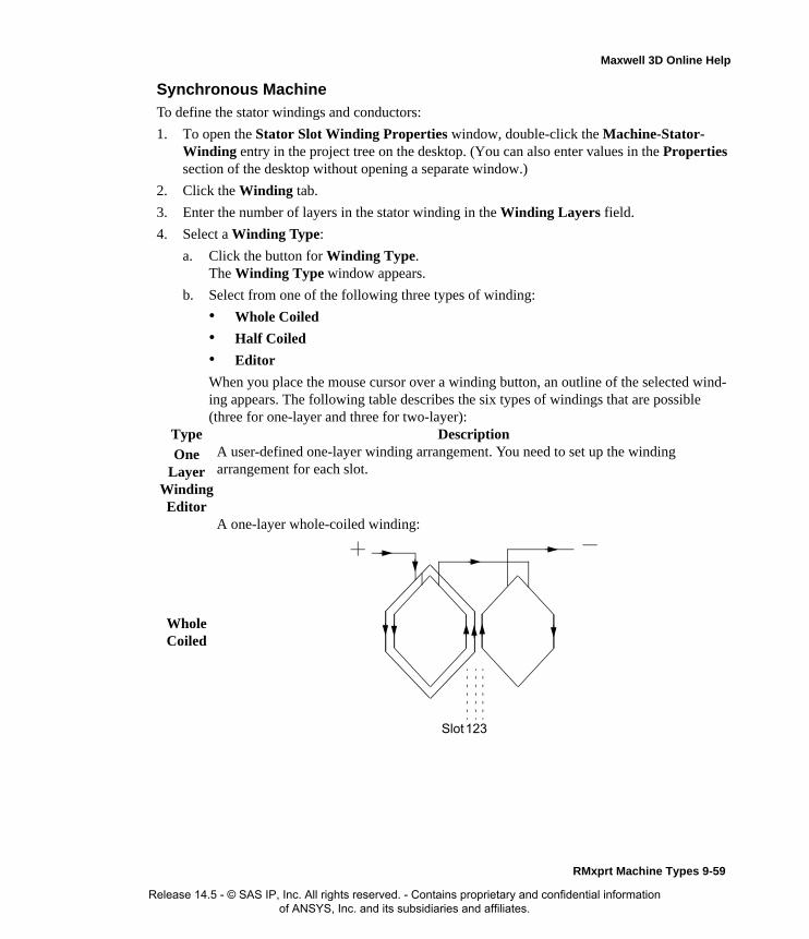
Maxwell 3D Online Help
Synchronous Machine
To define the stator windings and conductors:
1. To open the Stator Slot Winding Properties window, double-click the Machine-Stator-Winding entry in the project tree on the desktop. (You can also enter values in the Properties section of the desktop without opening a separate window.)
2. Click the Winding tab.
3. Enter the number of layers in the stator winding in the Winding Layers field.
4. Select a Winding Type:
a. Click the button for Winding Type.The Winding Type window appears.
b. Select from one of the following three types of winding:
• Whole Coiled
• Half Coiled
• Editor
When you place the mouse cursor over a winding button, an outline of the selected wind-ing appears. The following table describes the six types of windings that are possible (three for one-layer and three for two-layer):
Type Description
One Layer
Winding Editor
A user-defined one-layer winding arrangement. You need to set up the winding arrangement for each slot.
Whole Coiled
A one-layer whole-coiled winding:
123Slot
RMxprt Machine Types 9-59
Release 14.5 - © SAS IP, Inc. All rights reserved. - Contains proprietary and confidential information of ANSYS, Inc. and its subsidiaries and affiliates.

Maxwell 3D Online Help
Half Coiled
A one-layer concentric half-coiled winding:
EditorA user-defined two-layer winding arrangement. When you select 20, the Winding Editor opens, where you can specify a different winding arrangement for each slot.
Whole Coiled
A two-layer wave winding:
The phase belt for this winding configuration is equal to 360/2m, where m is the phase number.
123Slot
123Slot
9-60 RMxprt Machine Types
Release 14.5 - © SAS IP, Inc. All rights reserved. - Contains proprietary and confidential information of ANSYS, Inc. and its subsidiaries and affiliates.

Maxwell 3D Online Help
c. Once you have clicked a button to select a winding, click OK to close the Winding Type window and return to the Properties window.
5. Select the Winding Type for the stator.
Winding types 10 and 20 are user-defined. If you select either of these, a window appears, ask-ing you to define the name of the winding arrangement. The window closes when the user-
Half Coiled
A two-layer half-coiled winding:
There is only one coil per phase per pair of poles.
Note For a two-layer winding, if you check Constant Pitch in the Winding Editor, only the top layer needs to be defined; the bottom layer will be determined according to the coil pitch.
Note When you place the mouse cursor over the winding type, a schematic of the selected winding appears.
1 2 3Slot
RMxprt Machine Types 9-61
Release 14.5 - © SAS IP, Inc. All rights reserved. - Contains proprietary and confidential information of ANSYS, Inc. and its subsidiaries and affiliates.

Maxwell 3D Online Help
defined winding is entered. Select from the following winding types:
One-Layer
Winding Editor
A user-defined single-layer winding arrangement. When you select this type, enter the winding arrangement, and choose OK.
11 A one-layer whole-coiled winding:
123Slot
9-62 RMxprt Machine Types
Release 14.5 - © SAS IP, Inc. All rights reserved. - Contains proprietary and confidential information of ANSYS, Inc. and its subsidiaries and affiliates.

Maxwell 3D Online Help
12 A one-layer concentric half-coiled winding:
20 A user-defined winding arrangement. When you select this type, enter the winding arrangement, and choose OK.
21 A two-layer wave winding:
The phase belt for this winding configuration is equal to 360/2m, where m is the phase number.
123Slot
123Slot
RMxprt Machine Types 9-63
Release 14.5 - © SAS IP, Inc. All rights reserved. - Contains proprietary and confidential information of ANSYS, Inc. and its subsidiaries and affiliates.

Maxwell 3D Online Help
6. Select or enter the number of parallel branches in one phase of the winding in the Parallel Branches field.
7. Enter the total number of conductors in each stator slot in the Conductors per Slot field. This value is the number of turns per coil multiplied by the number of layers.
8. Enter the coil pitch, measured in number of slots, in the Coil Pitch field. The coil pitch is the number of slots separating one winding. For example, if a coil starts in slot 1 and ends in slot 6, it has a coil pitch of 5.
9. Enter the number of wires per conductor in the Number of Strands field. Enter 0 to have RMxprt auto-design this value.
10. Enter the thickness of the double-sided wire wrap in the Wire Wrap field. Enter 0 to automat-ically obtain this value from the wire library.
11. Select the Wire Size:
a. Click the button for Wire Size.The Wire Size window appears.
22 A two-layer winding:
1 2 3Slot
Insulation
Conductor
y
Wire Wrap = 2*y
9-64 RMxprt Machine Types
Release 14.5 - © SAS IP, Inc. All rights reserved. - Contains proprietary and confidential information of ANSYS, Inc. and its subsidiaries and affiliates.

Maxwell 3D Online Help
b. Select a value from the Wire Diameter pull-down list.
c. Select a wire gauge from the Gauge pull-down menu. You can select from the following options:
The gauge number is based on AWG settings. You can create your own wire table using Machine>Wire, and then you can select this wire table using the Tools>Options>Machine Options command.
d. When you are done setting the wire size, click OK to close the Wire Size window and return to the Properties window.
12. Click the End/Insulation tab.
13. Select or clear the Input Half-turn Length check box.
14. Do one of the following:
• If you selected Input Half-turn Length, then enter the half-turn length of the armature winding in the Half Turn Length field.
• If you cleared Input Half-turn Length, then enter the end length adjustment of the stator coils in the End Adjustment field. The end adjustment is the distance one end of the con-
<number>You can select a specific gauge number. When you select a gauge number, the Wire Diameter field is automatically updated.
USERThis option allows you to manually enter the Wire Diameter. This is useful when you want to enter a diameter that does not correspond to a particular wire gauge.
AUTO
This option sets the Wire Diameter to zero, and RMxprt automatically calculates the optimal value. The diameter information is then written to the output file when you analyze the design.
MIXED
This option allows you to define a conductor that is made of different size wires. For example, a single conductor may consist of 5 wires, 3 wires with a diameter of 0.21mm and 2 with a diameter of 0.13mm.
RMxprt Machine Types 9-65
Release 14.5 - © SAS IP, Inc. All rights reserved. - Contains proprietary and confidential information of ANSYS, Inc. and its subsidiaries and affiliates.

Maxwell 3D Online Help
ductor extends vertically beyond the end of the stator.
15. Enter the inner radius of the base corner in the Base Inner Radius field.
16. Enter the inner diameter of the coil tip in the Tip Inner Diameter field.
17. Enter the distance between two stator coils in the End Clearance field.
18. Enter the thickness of the slot liner insulation in the Slot Liner field.
19. Enter the thickness of the wedge insulation in the Wedge Thickness field.
20. Enter the thickness of the insulation layer in the Layer Insulation field.
21. Enter the limited slot fill factor for the wire design in the Limited Fill Factor field.
22. Click OK to close the Properties window.
EndAdjustment
StatorCoil
End of Stator
SlotInsulation
9-66 RMxprt Machine Types
Release 14.5 - © SAS IP, Inc. All rights reserved. - Contains proprietary and confidential information of ANSYS, Inc. and its subsidiaries and affiliates.

Maxwell 3D Online Help
Winding Editor for an Adjustable-Speed Synchronous Machine
For a adjustable-speed synchronous machine, you may want to specify a different number of con-ductors for each stator slot. The Winding Editor makes this possible by enabling you to specify the number of turns for each coil.
To specify the number of turns for each coil:
1. Click Machine>Winding>Edit Layout.The Winding Editor window appears.
2. In the table in the upper left, set which phase you want for each coil and which slot is the “in” and “out” slot for the current in each coil.
3. If you are working on a quarter or half model, you may want to specify a multiplier by clicking the Periodic Multiplier check box and specifying a value.
4. Select or deselect the Constant Turns or Constant Pitch check boxes, depending on whether you want to be able to change these setting in the table above. When these options are selected, you cannot change the turns or pitch.
5. When you are satisfied with the coil settings, click OK to close the Winding Editor window.
Defining Different Size Wires for an Adjustable Speed Synchronous MachineUse the Gauge option in the Wire Size dialog if you have a conductor that is made up different size wires.
To define different size wires:
1. In the Wire Size window, select MIXED from the Gauge pull-down menu.
2. Select either Round or Rectangular as the Wire Type.
3. Enter the appropriate wire data in the table:
• For a round wire:
• Enter the Diameter in the table.
• Enter a Number in the table to specify how many of the conductor’s wires have this diameter.
• For a rectangular wire:
• Enter the Width of the wire in the table.
• Enter the Thickness of the wire in the table.
• Enter the Fillet value in the table.
• Enter a Number in the table to specify how many of the conductor’s wires have this data.
4. Click Add to add the new wire data.
5. Repeat steps 3 and 4 for each size wire you want to add.
6. When you are finished defining the wires, click OK to close the Wire Size window and return
RMxprt Machine Types 9-67
Release 14.5 - © SAS IP, Inc. All rights reserved. - Contains proprietary and confidential information of ANSYS, Inc. and its subsidiaries and affiliates.

Maxwell 3D Online Help
to the RMxprt Properties window.
Stator Winding Data for Adjust-Speed Synchronous MachinesTo access the stator winding data, double-click the Machine-Stator-Winding entry in the project tree.
The Stator Winding Data Properties window contains the following fields:
Note For example, if one conductor is made up of 5 wires, and 3 of those wires have a diameter of 0.21mm, and the other 2 have a diameter of 0.13mm, then the mixed wire size table will have two lines. The first line will list Diameter = 0.21 and Number = 3. The second line will list Diameter = 0.13 and Number = 2. An equivalent wire diameter is displayed as Wire Size value in the Winding tab in the Properties window.
Winding tabWinding Layers The number of winding layers.
Winding Type The type of stator winding. Click the button to open the Winding Type window and choose from Whole Coiled, Half Coiled, and Editor.
Parallel Branches The number of parallel branches in the stator winding.
Conductors per Slot
The number of conductors per stator slot (0 for auto-design).
Coil Pitch The coil pitch measured in number of slots.
Number of Strands
The number of wires per conductor (0 for auto-design).
Wire Wrap The thickness of the double-sided wire wrap (0 to automatically obtain this value from the wire library).
Wire Size The diameter of the wire (0 for auto-design). Click the button to open the Wire Size window where you can specify units, wire type, diameter, and gauge.
End/Insulation tab
Input Half-turn Length
Select or clear this check box to specify whether or not you want to enter the half-turn length. When this check box is selected, the Half Turn Length field appears the next time you open the Properties window. When this check box is selected, the End Adjustment field appears instead.
Half Turn LengthThe half-turn length of the armature winding.
End Adjustment The end length adjustment of the stator coils, which is the distance one end of the conductor extends vertically beyond the end of the stator.
Base Inner Radius
The inner radius of the base corner.
Tip Inner Diameter
The inner diameter of the coil tip.
End Clearance The end clearance between two adjacent coils.
9-68 RMxprt Machine Types
Release 14.5 - © SAS IP, Inc. All rights reserved. - Contains proprietary and confidential information of ANSYS, Inc. and its subsidiaries and affiliates.

Maxwell 3D Online Help
Defining the Rotor Data for an Adjust-Speed Synchronous MachineThe rotor consists of copper bars in which current is induced by the magnetic fields produced by the stator windings. In the project tree, double-click Machine>Rotor and Machine-Rotor-Pole to define the rotor and the pole.
To define general stator data:
1. To open the Rotor Data Properties window, double-click the Machine>Rotor entry in the project tree on the desktop. (You can also enter values in the Properties section of the desktop without opening a separate window.)
2. Enter the outer diameter of the rotor in the Outer Diameter field.
3. Enter the inner diameter of the rotor in the Inner Diameter field.
4. Enter the length of the rotor core in the Length field.
5. Select a Steel Type for the rotor core:
a. Click the button for Steel Type.The Select Definition window appears.
b. Select a steel type from the list, or define a new steel type.
c. Click OK to close the Select Definition window and return to the Properties window.
6. Enter the stacking factor for the rotor core in the Stacking Factor field.
7. Select a Pole Type:
Slot Liner The thickness of the slot liner insulation.
Wedge Thickness The thickness of the wedge insulation.
Layer Insulation The thickness of the insulation layer.
Limited Fill Factor
The limited slot fill factor for the wire design.
RMxprt Machine Types 9-69
Release 14.5 - © SAS IP, Inc. All rights reserved. - Contains proprietary and confidential information of ANSYS, Inc. and its subsidiaries and affiliates.

Maxwell 3D Online Help
a. Click the button.The Select Pole Type window appears.
b. Click a button to select the desired pole type (1, 2, 3, 4, or 5). TIP: When you run the mouse over each option, the diagram changes to show that pole type.
c. Click OK to close the Select Pole Type window and return to the Properties window.
8. Click OK to close the Properties window.
Rotor Data for Adjust-Speed Synchronous Machines
To access the general rotor data, double-click the Machine>Rotor entry in the project tree.
The Rotor Data Properties window contains the following fields:
Defining the Rotor Pole for an Adjust-Speed Synchronous MachineThe rotor pole drives the electromagnetic field which is coupled with the stator windings. Use the Rotor Pole Data Properties window to define the rotor pole.
To define the rotor pole:
1. To open the Rotor Pole Data Properties window, double-click the Machine-Rotor-Pole entry in the project tree on the desktop. (You can also enter values in the Properties section of the desktop without opening a separate window.)
2. For all pole types except type 4, enter the ratio of the actual arc distance in relation to the max-
Note When you place the mouse cursor over a rotor type, an outline of the selected circuit type appears.
Outer Diameter The outer diameter of the rotor core.
Inner Diameter The inner diameter of the rotor core.
Length The length of the rotor core.
Steel Type The steel type of the rotor core. Click the button to open the Select Definition window.
Stacking Factor The stacking factor of the rotor core.
Pole Type The pole type for the rotor. Click this button to open the Select Pole Type window and select from the following types: 1, 2, 3, 4, 5.
Note Some of the fields in the Rotor Pole window change, or are inactive, depending on the Rotor Type you select.
9-70 RMxprt Machine Types
Release 14.5 - © SAS IP, Inc. All rights reserved. - Contains proprietary and confidential information of ANSYS, Inc. and its subsidiaries and affiliates.
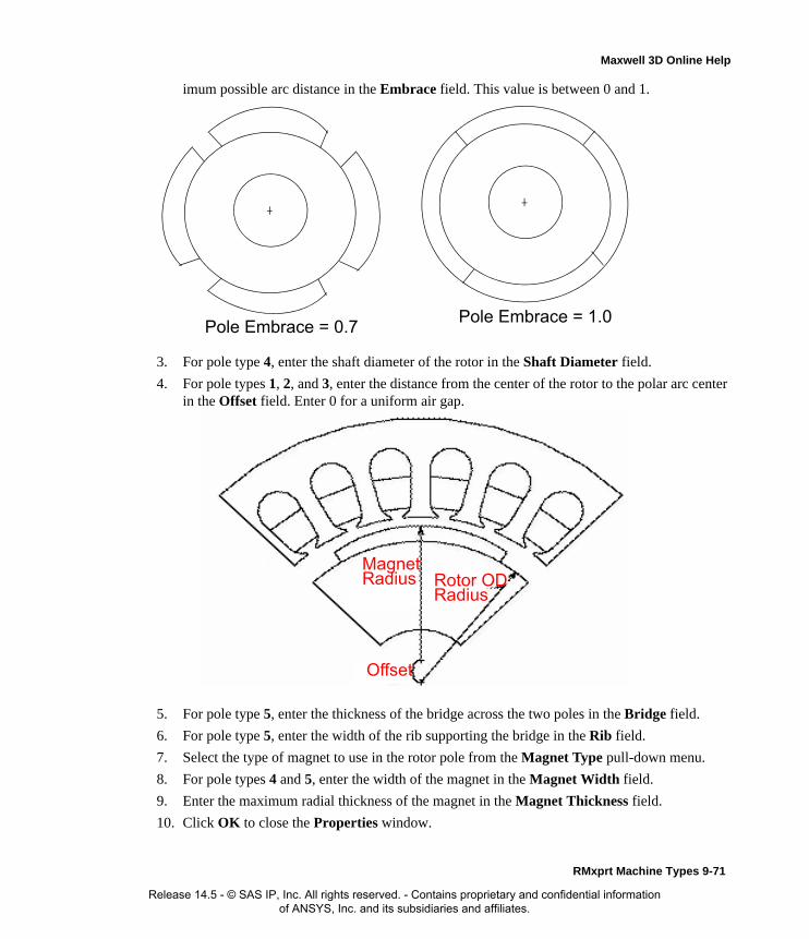
Maxwell 3D Online Help
imum possible arc distance in the Embrace field. This value is between 0 and 1.
3. For pole type 4, enter the shaft diameter of the rotor in the Shaft Diameter field.
4. For pole types 1, 2, and 3, enter the distance from the center of the rotor to the polar arc center in the Offset field. Enter 0 for a uniform air gap.
5. For pole type 5, enter the thickness of the bridge across the two poles in the Bridge field.
6. For pole type 5, enter the width of the rib supporting the bridge in the Rib field.
7. Select the type of magnet to use in the rotor pole from the Magnet Type pull-down menu.
8. For pole types 4 and 5, enter the width of the magnet in the Magnet Width field.
9. Enter the maximum radial thickness of the magnet in the Magnet Thickness field.
10. Click OK to close the Properties window.
Pole Embrace = 1.0Pole Embrace = 0.7
MagnetRadius
Offset
Rotor ODRadius
RMxprt Machine Types 9-71
Release 14.5 - © SAS IP, Inc. All rights reserved. - Contains proprietary and confidential information of ANSYS, Inc. and its subsidiaries and affiliates.

Maxwell 3D Online Help
Rotor Pole Data for Adjust-Speed Synchronous Machines
To access the pole rotor data, double-click the Machine-Rotor-Pole entry in the project tree.
The Rotor Pole Data Properties window contains the following fields:
Defining the Shaft Data for an Adjust-Speed Synchronous MachineTo define the shaft:
1. To open the Shaft Data Properties window, double-click the Machine>Shaft entry in the project tree on the desktop. (You can also enter values in the Properties section of the desktop without opening a separate window.)
2. Select or clear the Magnetic Shaft check box to specify whether or not the shaft is to be made of magnetic material.
3. Click OK to close the Properties window.
Shaft Data for Adjust-Speed Synchronous Machines
To access the shaft data, double-click the Machine>Shaft entry in the project tree.
The Shaft Data Properties window contains the following fields:
Setting Up Analysis Parameters for an Adjust-Speed Synchronous Machine
To define the solution data:
1. Right-click Analysis in the project tree, and click Add Solution Setup to open the Solution
Embrace The pole embrace. For pole types 1, 2, 3, and 5.
Shaft Diameter The shaft diameter of the rotor. For pole type 4.
Offset The pole-arc center offset from the rotor center (0 for a uniform air gap). For pole types 1, 2, and 3.
Bridge The thickness of the bridge across two adjacent poles. For pole type 5.
Rib The width of the rib at the center of two adjacent poles that support the bridge. For pole type 5.
Magnet Type The type of magnet. Click the button to open the Select Definition window. For all pole types.
Magnet Width The maximum width of the magnet. For pole types 4 and 5.
Magnet Thickness
The maximum thickness of the magnet. For all pole types.
Magnetic Shaft Select or clear this check box to indicate whether or not the shaft is made of magnetic material.
9-72 RMxprt Machine Types
Release 14.5 - © SAS IP, Inc. All rights reserved. - Contains proprietary and confidential information of ANSYS, Inc. and its subsidiaries and affiliates.

Maxwell 3D Online Help
Setup window.
2. Click the General tab. The Operation Type is automatically set to Motor for this machine type.
a. If Motor was selected for the Operation Type, select the Load Type used in the motor from the following options:
b. If Generator was selected for the Operation Type, select the Load Type used in the gener-ator from the following options: Infinite Bus or Independent Generator.
3. Enter the output power developed at the shaft of the motor in the Rated Output Power field.
4. Enter either the RMS line-to-line voltage (for AC control type), or the DC voltage (for DC and PWM control types) in the Rated Voltage field.
5. Enter the desired output speed of the motor at the load point in the Rated Speed field.
6. Enter the temperature at which the system functions in the Operating Temperature field.
7. Click the Adjust-Speed Synchronous Machine tab and select either Time or Frequency as the Domain for the solution.
8. Click OK to close the Solution Setup window.
Related Topics:
Solution Data for Adjust-Speed Synchronous Machines
Solution Data for Adjust-Speed Synchronous Machines
To access the solution data, right-click Analysis in the project tree, and click Add Solution Setup. For this machine type, there is only one tab, the General tab.
Note To enable selection of Generator for Adjust-Speed Synchronous Machines, the machine Control Type must be set to AC in its Properties window.
Const Speed The speed remains constant in the motor.
Const Power The output power remains constant in the motor.
Const Torque The torque remains constant regardless of the speed. In this case, Tload = Trated, given by the output power divided by the given rated speed.
Linear Torque The torque increases linearly with speed. In this case, Tload = Trated * (n/nrated) where Trated is given by the output power divided by the given rated speed.
Fan Load The load varies nonlinearly with speed. In this case, Tload = Trated * (n/nrated)2 where Trated is given by the output power divided by the given rated speed.
RMxprt Machine Types 9-73
Release 14.5 - © SAS IP, Inc. All rights reserved. - Contains proprietary and confidential information of ANSYS, Inc. and its subsidiaries and affiliates.

Maxwell 3D Online Help
The Solution Setup window contains the following fields:
Related Topics:
Setting Up Analysis Parameters for an Adjust-Speed Synchronous Machine
Operation Type The operation type is automatically set to Motor for this machine type.
Load Type Select from Const Speed, Const Power, Const Torque, Linear Torque, and Fan Load. The default is Const Power.
Rated Output Power
Type a value for the rated output voltage, and select the units.
Rated Voltage Type a value for the rated voltage, and select the units.
Rated Speed Type a value for the rated speed, and select the units.
Operating Temperature
Type a value for the operating temperature, and select the units.
9-74 RMxprt Machine Types
Release 14.5 - © SAS IP, Inc. All rights reserved. - Contains proprietary and confidential information of ANSYS, Inc. and its subsidiaries and affiliates.

Maxwell 3D Online Help
Permanent-Magnet DC MotorsAfter you have selected Permanent-Magnet DC Motors as your model type, you need to define the following:
• General data, such as the voltage, speed, and circuit type of the model.
• Stator data, such as the diameter, slot dimensions, and skew width of the stator.
• Stator pole data, such as its associated pole dimensions, type of steel, and pole magnet specifi-cations.
• Rotor data, such as the slot types and dimensions, slot data, and windings.
• Commutator and brush data, such as the commutator dimensions and brush length.
• Shaft data
• Solution data, such as rated output voltage and frequency.
Analysis Approach for PMDC MotorsFor a permanent-magnet DC motor, the stator is equipped with P pairs of permanent magnets, cre-ating P pairs of alternating north and south poles. The distribution of the magnetic field produced by the permanent magnet’s field flux is fixed with respect to the stator. The rotor is equipped with a distributed winding connected to a commutator that revolves together with the rotor.
A system of brushes is kept in permanent electrical contact with the commutator. When DC current is applied to the rotor winding (via the brushes and commutator), a torque is produced by the inter-action of the rotor (armature) currents and the field produced by the permanent magnets.
The commutator causes the armature to create a magnetic flux distribution that is fixed in space and whose axis is perpendicular to the axis of the field flux produced by the permanent magnets. For these motors, the commutator acts as a mechanical rectifier.
The performance of a permanent-magnet DC (PMDC) motor is computed by DC analysis only. The voltage equation of a PMDC motor is:
U = Ub + R1 * I + E
where Ub is the voltage drop of one-pair brushes, R1 is the armature resistance, E = Ke * is the back emf with Ke the back-emf constant in Vs/rad, and is the speed in rad/s. For a given speed
, armature current can be computed based on the applied voltage U, as shown below:
I = (U - Ub - Ke * )/R1
The shaft torque T2 is computed by:
T2 = Kt * I - Tfw
where Kt is the torque constant in Nm/A, which is numerically the same as Ke, and Tfw is the fric-tional torque.
The output power (mechanical power) is:
P2 = T2 *
The input power (electrical power) is:
ωω
ω
ω
ω
RMxprt Machine Types 9-75
Release 14.5 - © SAS IP, Inc. All rights reserved. - Contains proprietary and confidential information of ANSYS, Inc. and its subsidiaries and affiliates.

Maxwell 3D Online Help
P1 = P2 + Pfw + Pcua + Pb + PFe
where Pfw, Pcua, Pb, and PFe are frictional and wind loss, armature copper loss, brush drop loss, and iron-core loss, respectively.
The efficiency is:
eff = P2/P1 * 100%
Defining a Permanent-Magnet DC MotorThe general procedure for defining a permanent-magnet DC motor is as follows:
1. Insert the permanent-magnet DC motor into a new or existing project.
2. Double-click the Machine entry in the project tree to define the general data.
3. Double-click the Machine>Stator entry in the project tree to define the stator geometry.
4. Double-click the Machine-Stator-Pole entry in the project tree to define the stator pole dimensions.
5. Double-click the Machine>Rotor entry in the project tree to define the rotor geometry.
6. Double-click the Machine-Rotor-Slot entry in the project tree to define the rotor slot dimen-sions.
7. Double-click the Machine-Rotor-Winding entry in the project tree to define the rotor wind-ings and conductors.
8. Double-click the Machine>Commutator entry in the project tree to define the commutator and brush data.
9. Double-click the Machine>Shaft entry in the project tree to define the magnetism of the shaft.
10. Right-click Analysis in the project tree, and click Add Solution Setup to define the solution data.
11. Choose File>Save to save the project.
12. Choose RMxprt>Analyze to analyze the design.
Once analyzed, the model can be viewed in the Maxwell 2D Modeler, or it can be used to create a new Maxwell 2D project, and a new Maxwell 3D project.
Refer to the Permanent-Magnet DC Motor Problem application note, on the technical support page of the ANSYS web site, for a specific example of a permanent-magnet DC motor problem.
Defining the General Data for PMDC Motors
Use the General window to specify the rated output power, voltage values, circuit type, and speed of the DC motor.
To define the general data:
1. To open the General Data Properties window, double-click the Machine entry in the project tree on the desktop. (You can also enter values in the Properties section of the desktop without
Note When you place the cursor over an entry field in the data windows, a brief description of that field appears in the status bar at the bottom of the RMxprt window.
9-76 RMxprt Machine Types
Release 14.5 - © SAS IP, Inc. All rights reserved. - Contains proprietary and confidential information of ANSYS, Inc. and its subsidiaries and affiliates.

Maxwell 3D Online Help
opening a separate window.)
2. Enter the number of poles for the machine in the Number of Poles field. This value is the total number of poles in the stator (or the number of pole pairs multiplied by two).
3. Enter the energy loss due to friction at the given speed in the Frictional Loss field.
4. Enter the wind loss due to air resistance measured at the reference speed in the Wind Loss field.
5. Enter the given speed in the Reference Speed field.
6. Click OK to close the Properties window.
General Data for PMDC Motors
To access the general data, double-click the Machine entry in the project tree.
The General Data Properties window for a three-phase induction motor contains the following fields:
Defining the Stator Data for a PMDC Motor
The stator is the outer lamination stack where the polyphase voltage windings reside.
To define the general stator data:
1. To open the Stator Data Properties window, double-click the Machine>Stator entry in the project tree on the desktop. (You can also enter values in the Properties section of the desktop without opening a separate window.)
2. Enter the Outer Diameter of the stator.
3. Enter the Inner Diameter of the stator.
4. Enter the length of the stator core in the Length field.
5. Enter the stacking factor for the stator core in the Stacking Factor field. This value is a ratio of the effective magnetic length of the core, and ranges from 0 to 1. It is defined as the total length minus the total insulation from the laminations, divided by the total length. A value of 1 indicates that the stator is not laminated.
Note To use the Brush Press and Frictional Coefficient fields when you define the commutator and brush later in the Commutator/Brush Data window, enter 0 here for the Friction Loss.
Machine Type The machine type you selected when inserting a new RMxprt design (DC Permanent Magnet Motor).
Number of Poles The number of poles the machine contains.
Rotor Position Select whether the rotor is an Inner Rotor or Outer Rotor.
Frictional Loss The frictional energy loss (due to friction) measured at the reference speed.
Wind Loss The wind loss (due to air resistance) measured at the reference speed.
Reference Speed The given speed of reference.
RMxprt Machine Types 9-77
Release 14.5 - © SAS IP, Inc. All rights reserved. - Contains proprietary and confidential information of ANSYS, Inc. and its subsidiaries and affiliates.

Maxwell 3D Online Help
6. Click OK to close the Properties window.
Stator Data for PMDC Motors
To access the general stator data, double-click the Machine>Stator entry in the project tree.
The Stator Data Properties window contains the following fields:
Defining the Stator Pole for a PMDC MotorThe rotor pole drives the electromagnetic field which is coupled with the stator windings. Use the s Stator Pole Data Properties window to define the stator pole.
To define the rotor pole:
1. To open the Stator Pole Data Properties window, double-click the Machine-Stator-Pole entry in the project tree on the desktop. (You can also enter values in the Properties section of the desktop without opening a separate window.)
2. Enter the ratio of the actual arc distance in relation to the maximum possible arc distance in the
Outer Diameter The outer diameter of the stator core.
Inner Diameter The inner diameter of the stator core.
Length The length of the stator core.
Stacking Factor The stacking factor of the stator core.
Note For a two-pole machine, a pole embrace of 0.75 yields a magnet with a span of 135 degrees (based on 0.75*180 degrees).
9-78 RMxprt Machine Types
Release 14.5 - © SAS IP, Inc. All rights reserved. - Contains proprietary and confidential information of ANSYS, Inc. and its subsidiaries and affiliates.

Maxwell 3D Online Help
Embrace field. This value is between 0 and 1.
3. Enter the distance from the center of the stator to the magnet arc center in the Offset field. Enter 0 for a uniform air gap.
4. To select the type of magnet to use in the rotor pole:
a. Click the Magnet Type button.The Select Definition window appears.
b. Select or define a material for the magnet type.
c. Click OK to close the Select Definition window and return to the Properties window.
5. Enter the length of the magnet in the axial direction in the Magnet Length field.
6. Enter the maximum radial thickness of the magnet at the center of the pole in the Magnet Thickness field. To control the flux, the magnet’s thickness may vary.
7. Click OK to close the Properties window.
Stator Pole Data for PMDC Motors
To access the stator pole data, double-click the Machine-Stator-Pole entry in the project tree.
The Stator Pole Data Properties window contains the following fields:
Embrace The pole embrace.
Offset The pole-arc center offset from the stator center (0 for a uniform air gap).
Magnet Type The type of magnet. Click the button to open the Select Definition window.
Magnet Length The maximum length of the magnet.
Magnet Thickness The maximum thickness of the magnet.
RMxprt Machine Types 9-79
Release 14.5 - © SAS IP, Inc. All rights reserved. - Contains proprietary and confidential information of ANSYS, Inc. and its subsidiaries and affiliates.

Maxwell 3D Online Help
Defining the Rotor Data for a PMDC Motor
The rotor is equipped with slots containing copper conductors that are connected to the commuta-tor. The commutator acts as a mechanical rectifier in the motor.
Use the Rotor Data Properties, Rotor Slot Data Properties, and Rotor Winding Data Proper-ties windows to define the rotor slots, windings, and dimensions.
To define general rotor data:
1. To open the Rotor Data Properties window, double-click the Machine>Rotor entry in the project tree on the desktop. (You can also enter values in the Properties section of the desktop without opening a separate window.)
2. Enter the stacking factor for the rotor core in the Stacking Factor field.
3. Enter the Number of Slots in the rotor.
4. Select the Slot Type:
a. Click the button for the Slot Type.The Select Slot Type window appears.
b. Select a slot type (available types include 1 through 4)..
c. Click OK to close the Select Slot Type window and return to the Properties window.
5. Enter the outer diameter of the rotor in the Outer Diameter field.
6. Enter the inner diameter of the rotor in the Inner Diameter field.
7. Enter the length of the rotor core in the Length field.
8. Select a Steel Type for the rotor core:
a. Click the button for Steel Type.The Select Definition window appears.
b. Select a steel type from the list, or define a new steel type.
c. Click OK to close the Select Definition window and return to the Properties window.
9. Enter the skew width, measured in slot number, in the Skew Width field.
10. Click OK to close the Properties window.
Rotor Data for PMDC Motors
To access the general rotor data, double-click the Machine>Rotor entry in the project tree.
Note When you place the mouse cursor over the slot type, a schematic outline of the slot appears.
9-80 RMxprt Machine Types
Release 14.5 - © SAS IP, Inc. All rights reserved. - Contains proprietary and confidential information of ANSYS, Inc. and its subsidiaries and affiliates.
Maxwell 3D Online Help
The Rotor Data Properties window contains the following fields:
Defining the Rotor Slots for a PMDC MotorTo define the physical dimensions of the rotor slots:
1. To open the Rotor Slot Data Properties window, double-click the Machine-Rotor-Slot entry in the project tree on the desktop. (You can also enter values in the Properties section of the desktop without opening a separate window.)
2. Optionally, to automatically design the dimensions of slots Hs2, Bs1, and Bs2, select the Auto Design check box.
3. Enter the available slot dimensions.
4. Click OK to close the Properties window.
Rotor Slot Data for PMDC MotorsTo access the stator slot data, double-click the Machine-Rotor-Slot entry in the project tree.
Stacking Factor The stacking factor of the rotor core.
Number of Slots The number of slots the rotor core contains.
Slot Type The type of slots in the rotor core. Click the button to open the Select Slot Type window.
Outer Diameter The outer diameter of the rotor core.
Inner Diameter The inner diameter of the rotor core.
Length The length of the rotor core.
Steel Type The steel type of the rotor core. Click the button to open the Select Definition window.
Skew Width The skew width measured in slot number.
Hs0 Always available.
Hs2 Available only when Auto Design is cleared. When Auto Design is selected, this slot dimension is determined automatically.
Bs0 Always available.
Bs1 Available only when Auto Design is cleared. When Auto Design is selected, this slot dimension is determined automatically. When Parallel Tooth is selected, this slot dimension is determined based on the value entered in the Tooth Width field.
Bs2 Available only when Auto Design is cleared. When Auto Design is selected, this slot dimension is determined automatically. When Parallel Tooth is selected, this slot dimension is determined based on the value entered in the Tooth Width field.
Rs Rs is added when the slot type is 3 or 4.
RMxprt Machine Types 9-81
Release 14.5 - © SAS IP, Inc. All rights reserved. - Contains proprietary and confidential information of ANSYS, Inc. and its subsidiaries and affiliates.

Maxwell 3D Online Help
The Rotor Slot Data Properties window contains the following fields:
Defining the Rotor Windings and Conductors for a PMDC MotorTo define the rotor windings, wires, and conductors:
1. To open the Rotor Slot Winding Properties window, double-click the Machine-Rotor-Winding entry in the project tree on the desktop. (You can also enter values in the Properties section of the desktop without opening a separate window.)
2. Click the Winding tab.
3. Select a Winding Type:
a. Click the button for Winding Type.The Winding Type window appears.
b. Select from one of the following three types of winding:
• Lap
• Wave
• Frog Leg
4. Enter the number of windings in the Multiplex Number field (1 for a single winding, 2 for double windings, 3 for triple windings). For a lap winding, the multiplex number is the number of commutators between the start and end of one winding, and the number of parallel branches is equal to the number of poles multiplied by the multiplex number. For a wave winding, the
Auto Design Select or clear this to enable or disable auto-design of slots Hs2, Bs1, and Bs2. When this check box is selected, only two other fields appear in the window: Hs0 and Bs0.
Hs0 A slot dimension (see the diagram shown in the modeling window when Machine-Rotor-Slot is selected).
Hs2 A slot dimension (see the diagram shown in the modeling window when Machine-Rotor-Slot is selected).
Bs0 A slot dimension (see the diagram shown in the modeling window when Machine-Rotor-Slot is selected).
Bs1 A slot dimension (see the diagram shown in the modeling window when Machine-Rotor-Slot is selected).
Bs2 A slot dimension (see the diagram shown in the modeling window when Machine-Rotor-Slot is selected).
Rs A slot dimension. (see the diagram shown in the modeling window when Machine-Stator-Slot is selected). Rs is added when the slot type is 3 or 4.
Rs A slot dimension. (see the diagram shown in the modeling window when Machine-Stator-Slot is selected). Rs is added when the slot type is 3 or 4.
9-82 RMxprt Machine Types
Release 14.5 - © SAS IP, Inc. All rights reserved. - Contains proprietary and confidential information of ANSYS, Inc. and its subsidiaries and affiliates.

Maxwell 3D Online Help
number of parallel branches equals the multiplex number multiplied by two.
5. Enter the number of virtual slots per each real slot in the Virtual Slots field. The rotor is assumed to have two layers of conductors, an upper and a lower layer. Each layer of conduc-tors can have a number of windings, which are referred to as virtual slots.
6. Enter the total number of conductors in each rotor slot in the Conductors per Slot field. This value is the number of turns per coil multiplied by the number of layers. This value is the total number of conductors in one real full rotor slot.
7. Enter the coil pitch, measured in number of slots, in the Coil Pitch field. The coil pitch is the number of slots separating one winding. For example, if a coil starts in slot 1 and ends in slot 6, it has a coil pitch of 5.
8. Enter the number of wires per conductor in the Number of Strands field. Enter 0 to have RMxprt auto-design this value.
9. Enter the thickness of the double-sided wire wrap in the Wire Wrap field. Enter 0 to automat-
Note For example, the upper and lower layer can have two windings each, which would yield a virtual slot number of two; for a 12 slot machine, this would yield 24 commutation segments.
RMxprt Machine Types 9-83
Release 14.5 - © SAS IP, Inc. All rights reserved. - Contains proprietary and confidential information of ANSYS, Inc. and its subsidiaries and affiliates.

Maxwell 3D Online Help
ically obtain this value from the wire library.
10. Select the Wire Size:
a. Click the button for Wire Size.The Wire Size window appears.
b. Select a value from the Wire Diameter pull-down list.
c. Select a wire gauge from the Gauge pull-down menu. You can select from the following options:
The gauge number is based on AWG settings. You can create your own wire table using Machine>Wire, and then you can select this wire table using the Tools>Options>Machine Options command.
d. When you are done setting the wire size, click OK to close the Wire Size window and return to the Properties window.
11. Click the End/Insulation tab.
12. Select or clear the Input Half-turn Length check box.
13. Do one of the following:
• If you selected Input Half-turn Length, then enter the half-turn length of the armature winding in the Half Turn Length field.
<number>You can select a specific gauge number. When you select a gauge number, the Wire Diameter field is automatically updated.
USERThis option allows you to manually enter the Wire Diameter. This is useful when you want to enter a diameter that does not correspond to a particular wire gauge.
AUTO
This option sets the Wire Diameter to zero, and RMxprt automatically calculates the optimal value. The diameter information is then written to the output file when you analyze the design.
MIXED
This option allows you to define a conductor that is made of different size wires. For example, a single conductor may consist of 5 wires, 3 wires with a diameter of 0.21mm and 2 with a diameter of 0.13mm.
Insulation
Conductor
y
Wire Wrap = 2*y
9-84 RMxprt Machine Types
Release 14.5 - © SAS IP, Inc. All rights reserved. - Contains proprietary and confidential information of ANSYS, Inc. and its subsidiaries and affiliates.
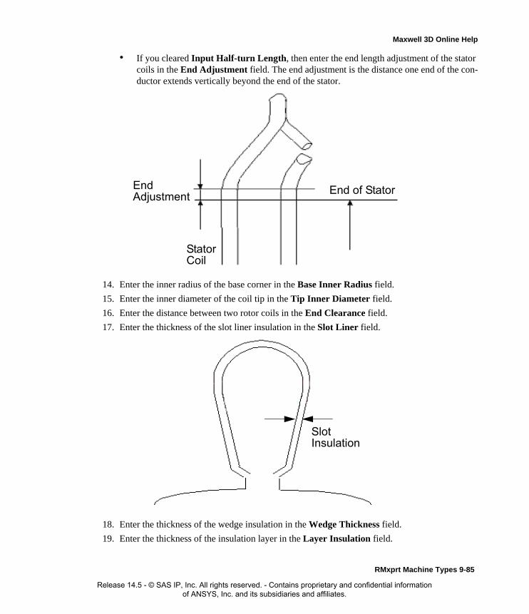
Maxwell 3D Online Help
• If you cleared Input Half-turn Length, then enter the end length adjustment of the stator coils in the End Adjustment field. The end adjustment is the distance one end of the con-ductor extends vertically beyond the end of the stator.
14. Enter the inner radius of the base corner in the Base Inner Radius field.
15. Enter the inner diameter of the coil tip in the Tip Inner Diameter field.
16. Enter the distance between two rotor coils in the End Clearance field.
17. Enter the thickness of the slot liner insulation in the Slot Liner field.
18. Enter the thickness of the wedge insulation in the Wedge Thickness field.
19. Enter the thickness of the insulation layer in the Layer Insulation field.
EndAdjustment
StatorCoil
End of Stator
SlotInsulation
RMxprt Machine Types 9-85
Release 14.5 - © SAS IP, Inc. All rights reserved. - Contains proprietary and confidential information of ANSYS, Inc. and its subsidiaries and affiliates.

Maxwell 3D Online Help
20. Enter the limited slot fill factor for the wire design in the Limited Fill Factor field.
21. Select the type of equalizer connection from the Equalizer Connection pull-down menu. Select from None, Half, or Full.
22. Click OK to close the Properties window.
Defining Different Size Wires for a PMDC Motor
Use the Gauge option if you have a conductor that is made up different size wires.
To define different size wires:
1. In the Wire Size window, select MIXED from the Gauge pull-down menu.
2. Select either Round or Rectangular as the Wire Type.
3. Enter the appropriate wire data in the table:
• For a round wire:
• Enter the Diameter in the table.
• Enter a Number in the table to specify how many of the conductor’s wires have this diameter.
• For a rectangular wire:
• Enter the Width of the wire in the table.
• Enter the Thickness of the wire in the table.
• Enter the Fillet value in the table.
• Enter a Number in the table to specify how many of the conductor’s wires have this data.
4. Click Add to add the new wire data.
5. Repeat steps 3 and 4 for each size wire you want to add.
6. When you are finished defining the wires, click OK to close the Wire Size window and return to the RMxprt Properties window.
Rotor Winding Data for PMDC Motors
To access the stator winding data, double-click the Machine-Rotor-Winding entry in the project tree.
Note For example, if one conductor is made up of 5 wires, and 3 of those wires have a diameter of 0.21mm, and the other 2 have a diameter of 0.13mm, then the mixed wire size table will have two lines. The first line will list Diameter = 0.21 and Number = 3. The second line will list Diameter = 0.13 and Number = 2. An equivalent wire diameter is displayed as Wire Size value in the Winding tab in the Properties window.
9-86 RMxprt Machine Types
Release 14.5 - © SAS IP, Inc. All rights reserved. - Contains proprietary and confidential information of ANSYS, Inc. and its subsidiaries and affiliates.

Maxwell 3D Online Help
The Rotor Winding Data Properties window contains the following fields:
Winding tabWinding Type The type of rotor winding. Click the button to open the Winding Type window and choose from Lap, Wave, and Frog Leg.
Multiplex Number Single, double, or triple windings (1, 2, or 3).
Virtual Slots The number of virtual slots per real slot.
Conductors per Slot
The number of conductors per rotor slot (0 for auto-design).
Coil Pitch The coil pitch measured in number of slots.
Number of Strands
The number of wires per conductor (0 for auto-design).
Wire Wrap The thickness of the double-sided wire wrap (0 to automatically obtain this value from the wire library).
Wire Size The diameter of the wire (0 for auto-design). Click the button to open the Wire Size window where you can specify units, wire type, diameter, and gauge.
End/Insulation tab
Input Half-turn Length
Select or clear this check box to specify whether or not you want to enter the half-turn length. When this check box is selected, the Half Turn Length field appears the next time you open the Properties window. When this check box is selected, the End Adjustment field appears instead.
Half Turn Length The half-turn length of the armature winding.
Base Inner Radius The inner radius of the base corner.
Tip Inner Diameter
The inner diameter of the coil tip.
End Clearance The end clearance between two adjacent coils.
Slot Liner The thickness of the slot liner insulation.
Wedge Thickness The thickness of the wedge insulation.
Layer Insulation The thickness of the insulation layer.
RMxprt Machine Types 9-87
Release 14.5 - © SAS IP, Inc. All rights reserved. - Contains proprietary and confidential information of ANSYS, Inc. and its subsidiaries and affiliates.
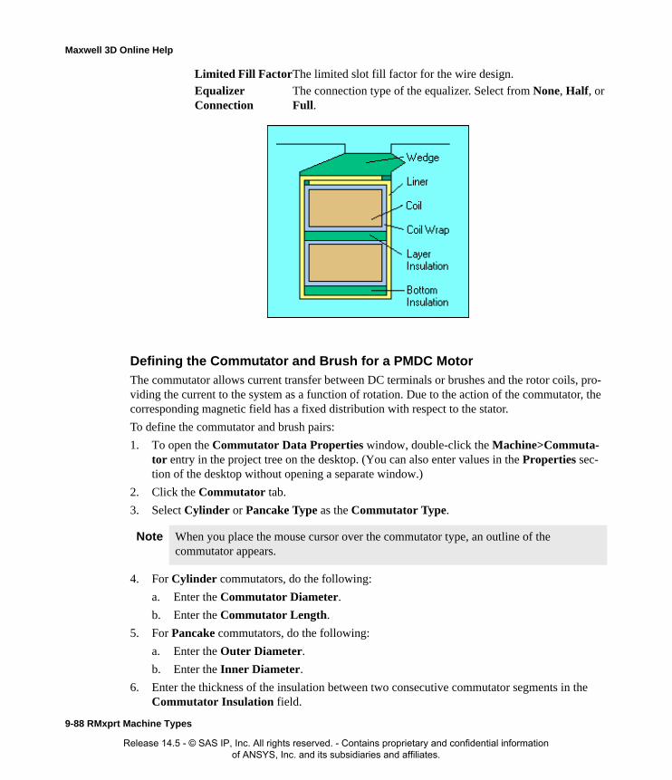
Maxwell 3D Online Help
Defining the Commutator and Brush for a PMDC MotorThe commutator allows current transfer between DC terminals or brushes and the rotor coils, pro-viding the current to the system as a function of rotation. Due to the action of the commutator, the corresponding magnetic field has a fixed distribution with respect to the stator.
To define the commutator and brush pairs:
1. To open the Commutator Data Properties window, double-click the Machine>Commuta-tor entry in the project tree on the desktop. (You can also enter values in the Properties sec-tion of the desktop without opening a separate window.)
2. Click the Commutator tab.
3. Select Cylinder or Pancake Type as the Commutator Type.
4. For Cylinder commutators, do the following:
a. Enter the Commutator Diameter.
b. Enter the Commutator Length.
5. For Pancake commutators, do the following:
a. Enter the Outer Diameter.
b. Enter the Inner Diameter.
6. Enter the thickness of the insulation between two consecutive commutator segments in the Commutator Insulation field.
Limited Fill FactorThe limited slot fill factor for the wire design.
Equalizer Connection
The connection type of the equalizer. Select from None, Half, or Full.
Note When you place the mouse cursor over the commutator type, an outline of the commutator appears.
9-88 RMxprt Machine Types
Release 14.5 - © SAS IP, Inc. All rights reserved. - Contains proprietary and confidential information of ANSYS, Inc. and its subsidiaries and affiliates.

Maxwell 3D Online Help
7. Click the Brush tab.
8. Enter the Brush Width.
9. Enter the Brush Length.
10. Enter the number of brush pairs when using a wave armature winding in the Brush Pairs field.
11. Enter the angle of displacement from the neutral axis, in mechanical degrees, in the Brush Dis-placement field.
12. Enter the voltage drop across one brush pair in the Brush Drop field.
13. Enter the mechanical pressure of the brushes as they press against the commutator in the Brush Press field.
14. Enter the Frictional Coefficient of the brush.
15. Click OK to close the Properties window.
Commutator and Brush Data for PMDC MotorsTo access the commutator and brush data, double-click the Machine>Commutator entry in the project tree.
The Commutator Data Properties window contains the following fields:
Note The brush displacement is positive for the counter-clockwise direction. For example, if the rotor turns clockwise and the brush displacement is also clockwise, then the angle is negative; if the rotor turns clockwise but the brush displacement is counter-clockwise, then the angle is positive.
Note If the Friction Loss field is used in the General window, the Brush Press and Frictional Coefficient fields will be hidden in the Commutator/Brush window. These fields are shown only when the Friction Loss field in the General window is set to zero.
Commutator tab
Commutator Type The type of commutator. Click the button to open the Select Commutator Type window and select from Cylinder or Pancake.
Commutator Diameter
For a Cylinder commutator type, the diameter of the commutator.
Commutator Length
For a Cylinder commutator type, the length of the commutator.
Outer Diameter For a Pancake commutator type, the outer diameter of the commutator.
Inner Diameter For a Pancake commutator type, the inner diameter of the commutator.
Commutator Insulation
The thickness of the insulation between the two commutator bars.
RMxprt Machine Types 9-89
Release 14.5 - © SAS IP, Inc. All rights reserved. - Contains proprietary and confidential information of ANSYS, Inc. and its subsidiaries and affiliates.

Maxwell 3D Online Help
Defining the Shaft Data for a PMDC Motor
To define the shaft:
1. To open the Shaft Data Properties window, double-click the Machine>Shaft entry in the project tree on the desktop. (You can also enter values in the Properties section of the desktop without opening a separate window.)
2. Select or clear the Magnetic Shaft check box to specify whether or not the shaft is to be made of magnetic material.
3. Click OK to close the Properties window.
Shaft Data for PMDC Motors
To access the shaft data, double-click the Machine>Shaft entry in the project tree.
The Shaft Data Properties window contains the following fields:
Setting Up Analysis Parameters for a PMDC MotorTo define the solution data:
1. To open the Solution Setup window, right-click Analysis in the project tree, and click Add Solution Setup.
2. Click the General tab. The Operation Type is automatically set to Motor for this machine type.
3. Select the Load Type used in the motor from the following options:
Brush tab Brush Width The width of the brush.
Brush Length The length of the brush.
Brush Pairs The number of brush pairs.
Brush Displacement
The displacement of the brush from the neutral position, in mechanical degrees (positive for anti-rotating direction).
Brush Drop The voltage drop across a one-pair brush.
Brush Press The brush press per unit area. (Available only when Frictional Loss is set to zero for the machine.)
Frictional Coefficient
The frictional coefficient of the brush. (Available only when Frictional Loss is set to zero for the machine.)
Magnetic Shaft Select or clear this check box to indicate whether or not the shaft is made of magnetic material.
Const Speed The speed remains constant in the motor.
Const Power The output power remains constant in the motor.
9-90 RMxprt Machine Types
Release 14.5 - © SAS IP, Inc. All rights reserved. - Contains proprietary and confidential information of ANSYS, Inc. and its subsidiaries and affiliates.
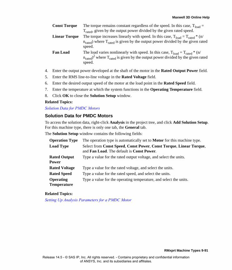
Maxwell 3D Online Help
4. Enter the output power developed at the shaft of the motor in the Rated Output Power field.
5. Enter the RMS line-to-line voltage in the Rated Voltage field.
6. Enter the desired output speed of the motor at the load point in the Rated Speed field.
7. Enter the temperature at which the system functions in the Operating Temperature field.
8. Click OK to close the Solution Setup window.
Related Topics:
Solution Data for PMDC Motors
Solution Data for PMDC Motors
To access the solution data, right-click Analysis in the project tree, and click Add Solution Setup. For this machine type, there is only one tab, the General tab.
The Solution Setup window contains the following fields:
Related Topics:
Setting Up Analysis Parameters for a PMDC Motor
Const Torque The torque remains constant regardless of the speed. In this case, Tload = Trated, given by the output power divided by the given rated speed.
Linear Torque The torque increases linearly with speed. In this case, Tload = Trated * (n/nrated) where Trated is given by the output power divided by the given rated speed.
Fan Load The load varies nonlinearly with speed. In this case, Tload = Trated * (n/nrated)2 where Trated is given by the output power divided by the given rated speed.
Operation Type The operation type is automatically set to Motor for this machine type.
Load Type Select from Const Speed, Const Power, Const Torque, Linear Torque, and Fan Load. The default is Const Power.
Rated Output Power
Type a value for the rated output voltage, and select the units.
Rated Voltage Type a value for the rated voltage, and select the units.
Rated Speed Type a value for the rated speed, and select the units.
Operating Temperature
Type a value for the operating temperature, and select the units.
RMxprt Machine Types 9-91
Release 14.5 - © SAS IP, Inc. All rights reserved. - Contains proprietary and confidential information of ANSYS, Inc. and its subsidiaries and affiliates.

Maxwell 3D Online Help
9-92 RMxprt Machine Types
Release 14.5 - © SAS IP, Inc. All rights reserved. - Contains proprietary and confidential information of ANSYS, Inc. and its subsidiaries and affiliates.

Maxwell 3D Online Help
Three-Phase Synchronous MachinesAfter you have selected Three-Phase Synchronous Machines as your model type, you need to define the following:
• General data, such as the unit system, power, and voltage.
• Stator data, such as the slot types and dimensions, stator diameter, skew width, and lamina-tions.
• Optional stator Vent data.
• Winding data, such as the parallel branches, conductors, and wire dimensions.
• Rotor pole data, such as its associated pole-body dimensions and air gaps.
• Optional Rotor damper data, such as the damper dimensions, rings, and material properties.
• Rotor winding data and the winding control parameters.
• Shaft Data
• Solution data, such as specifying motor or generator application, and rated output voltage and frequency.
Also see the Analysis Approach for Three-Phase Synchronous Machines.
Analysis Approach for Three-Phase Synchronous MachinesThe three-phase salient-pole synchronous electric machine has two types: the generator and the motor. Their basic structures are the same. Three-phase synchronous generators are the main source of electrical energy for industrial, commercial, and private use. They receive mechanical energy at the shaft and transform it into electrical energy. The rotor is equipped with a multi-pole winding excited by a DC source. The stator is equipped with a three-phase winding that has a sinusoidal spatial distribution. The spinning rotor produces a rotating magnetic field in the air gap of the machine. The frequency of the voltage induced in the stator is given by f=pv, where p is the number of pairs of poles, and v is the velocity of the rotor. The machine is capable of producing both active and reactive power as required by the load connected at the stator phasor.
The three-phase salient-pole synchronous electric machine has two types: the generator and the motor. Their basic structures are the same. Usually the frequency-domain phasor diagram is
RMxprt Machine Types 9-93
Release 14.5 - © SAS IP, Inc. All rights reserved. - Contains proprietary and confidential information of ANSYS, Inc. and its subsidiaries and affiliates.
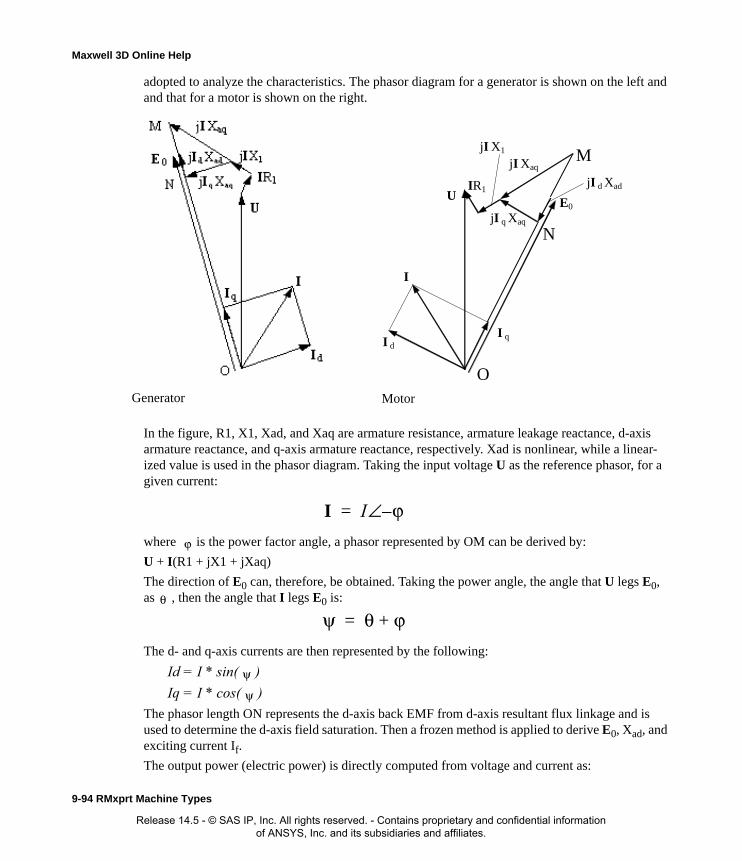
Maxwell 3D Online Help
adopted to analyze the characteristics. The phasor diagram for a generator is shown on the left and and that for a motor is shown on the right.
In the figure, R1, X1, Xad, and Xaq are armature resistance, armature leakage reactance, d-axis armature reactance, and q-axis armature reactance, respectively. Xad is nonlinear, while a linear-ized value is used in the phasor diagram. Taking the input voltage U as the reference phasor, for a given current:
where is the power factor angle, a phasor represented by OM can be derived by:
U + I(R1 + jX1 + jXaq)
The direction of E0 can, therefore, be obtained. Taking the power angle, the angle that U legs E0, as , then the angle that I legs E0 is:
The d- and q-axis currents are then represented by the following:
Id = I * sin( )
Iq = I * cos( )
The phasor length ON represents the d-axis back EMF from d-axis resultant flux linkage and is used to determine the d-axis field saturation. Then a frozen method is applied to derive E0, Xad, and exciting current If.
The output power (electric power) is directly computed from voltage and current as:
O
I
I dI q
U
IR1
jI Xaq
jI q Xaq E0
jI d Xad
M jI X1
N
Generator Motor
I I ϕ–∠=
ϕ
θ
ψ θ ϕ+=
ψ
ψ
9-94 RMxprt Machine Types
Release 14.5 - © SAS IP, Inc. All rights reserved. - Contains proprietary and confidential information of ANSYS, Inc. and its subsidiaries and affiliates.
Maxwell 3D Online Help
P2 = 3*U*I*cos( )
The input power (mechanical power) is defined as:
P1 = P2 + Pfw + Pcua + PFe + Padd + Pcuf + Pex
where Pfw, Pcua, PFe, Padd, Pcuf and Pex are frictional and wind loss, armature copper loss, iron-core loss, additional loss, field winding copper loss, and exciter loss, respectively.
The input mechanical shaft torque is:
T1 = P1/
where SYMBOL is synchronous speed in rad/s.
The efficiency is computed by:
eff = P2/P1 * 100%
Main Features
• Adapted to both Synchronous Motor and Generator
The structures of the salient-pole synchronous motor and the generator are basically the same, but their phasor relationships and the computation methods are slightly different, their output characteristics data are also different. This is specified in the solution setup.
• Auto Arrangement of Three-phase Windings
Almost all commonly used three-phase single- and double-layer, half- and whole-type ac windings (including fractional-pitch windings) can be automatically arranged. Users do not need to define coils one by one. RMxprt also supports a double-layer winding with half-turn coils which are auto-arranged in the order of even, odd, even, odd, …, and even, odd, as long as it is physically possible.
When a designer adopts single-layer whole-coiled windings, RMxprt will perform winding arrangement optimization to minimize the average coil pitch. When asymmetric three-phase windings are used, winding arrangement is optimized in such a way that minimum negative-sequence and zero-sequence components are achieved.
• Winding Editor Supporting Any Single- and Double-Layer Windings
Besides taking advantage of the winding auto-arrangement function in RMxprt, users can also specify any special winding by using of the Winding Editor function.
In Winding Editor, through modification of phase belonging, number of turns, in-slot and out-slot number of each coil, it is possible to design single- and double-layer winding arrangement for any purposes.
• Analyze Air-Gap Magnetic Field Distribution
For both uniform and non-uniform air gaps, Schwarz-Christopher Transformation is adopted to solve for the air-gap magnetic field distribution.
• Analyze EMF Waveform and Total Harmonic Distortion (THD)
Based on the analysis of the air-gap magnetic field waveform, taking into account coil short pitch, winding distribution, skew slot, winding connection, load effects and other factors, the emf waveforms in the coils and the windings are analyzed to solve for the emf distortion fac-
ϕ
ω
RMxprt Machine Types 9-95
Release 14.5 - © SAS IP, Inc. All rights reserved. - Contains proprietary and confidential information of ANSYS, Inc. and its subsidiaries and affiliates.

Maxwell 3D Online Help
tors.
• Analyze Dynamic Parameters of Damping Winding
Different from the squirrel-cage winding of the induction machine, the damping winding of the salient-pole synchronous machine is located in the surface of magnetic field poles, which devi-ates greatly along the d- and the q-axes. Furthermore, the connection of damping bars has sev-eral forms. The bars under each pole could be connected, but not connected with those under other poles. All the bars could be connected together. The bars could be connected through end-plate. RMxprt can deal with all those complicated situations and give the dynamic param-eters for the damping winding.
Defining a Three-Phase Synchronous MachineThe general procedure for defining a three-phase synchronous machine is as follows:
1. Insert a three-phase synchronous machine into a existing or new project.
2. Double-click the Machine entry in the project tree to define the general data.
3. Double-click the Machine-Stator entry in the project tree to define the stator geometry.
4. Double-click the Machine-Stator-Slot entry in the project tree to define the stator slot dimen-sions.
5. Optionally, you can add a vent to, or remove an existing vent from the stator. To add a vent, select the stator, and right-click to display the pop-up menu for Insert Vent.
6. Double-click the Machine-Stator-Winding entry in the project tree to define the stator wind-ings, conductors, and insulation data.
7. Double-click the Machine-Rotor entry in the project tree to define the general rotor geometry, the pole data, and the insulation data.
8. Double-click the Machine-Rotor-Winding entry in the project tree to define the rotor conduc-tors and windings.
9. Optionally, you can add a damper to the design or remove an existing damper. To add a damper, use Machine-Insert Damper. This inserts the damper in the project tree under the rotor. You must then specify the slot type and other properties for the damper.
10. Optionally, you can add a vent to, or remove an existing vent from the rotor. To add a vent select the rotor, and right-click to display the pop-up menu. Use Insert Vent.
11. Double-click the Machine-Shaft entry in the project tree to define the magnetism of the shaft.
12. Right-click Analysis in the project tree, and click Add Solution Setup to define this solution data.
13. Choose File>Save to save the project.
14. Choose RMxprt>Analyze to analyze the design.
Note When you place the cursor over an entry field, a brief description of that field appears in the status bar at the bottom of the RMxprt window.
9-96 RMxprt Machine Types
Release 14.5 - © SAS IP, Inc. All rights reserved. - Contains proprietary and confidential information of ANSYS, Inc. and its subsidiaries and affiliates.
Maxwell 3D Online Help
Once the design is analyzed, the model can be viewed in the Maxwell 2D Modeler, or it can be used to create a new Maxwell 2D project, and a Maxwell 3D design.
Defining the General Data for a Three-Phase Synchronous Machine
Use the General Data Properties window to define the power settings, speed, and efficiency of the generator. This window allows you to define the basic parameters of the synchronous generator, such as power, voltage, winding connections, and losses.
To define the general data:
1. To open the General Data Properties window, double-click the Machine entry in the project tree on the desktop. (You can also enter values in the Properties section of the desktop without opening a separate window.)
2. Enter the number of poles for the machine in the Number of Poles field. This value is the total number of poles in the stator (or the number of pole pairs multiplied by two).
3. Enter the power lost through frictional forces in the Frictional Loss field.
4. Enter the wind loss measured at the reference speed in the Wind Loss field.
5. Enter the given speed in the Reference Speed field.
6. Click OK to close the Properties window.
General Data for Three-Phase Synchronous MachinesTo access the general data, double-click the Machine entry in the project tree.
The General Data Properties window for a three-phase induction motor contains the following fields:
Defining the Stator for a Three-Phase Synchronous MachineUse the Stator windows to define the slot dimensions, stacking factors, air ducts, and insulation of the stator. The stator is the outer lamination stack where the three-phase windings reside.
To define general stator data:
1. To open the Stator Data Properties window, double-click the Machine>Stator entry in the project tree on the desktop. (You can also enter values in the Properties section of the desktop without opening a separate window.)
2. Enter the Outer Diameter of the stator.
3. Enter the Inner Diameter of the stator.
Machine Type The machine type you selected when inserting a new RMxprt design (Three Phase Synchronous Machine).
Number of Poles The number of poles the machine contains.
Frictional Loss The frictional energy loss (due to friction) measured at the reference speed.
Wind Loss The wind loss (due to air resistance) measured at the reference speed.
Reference Speed The given speed of reference.
RMxprt Machine Types 9-97
Release 14.5 - © SAS IP, Inc. All rights reserved. - Contains proprietary and confidential information of ANSYS, Inc. and its subsidiaries and affiliates.
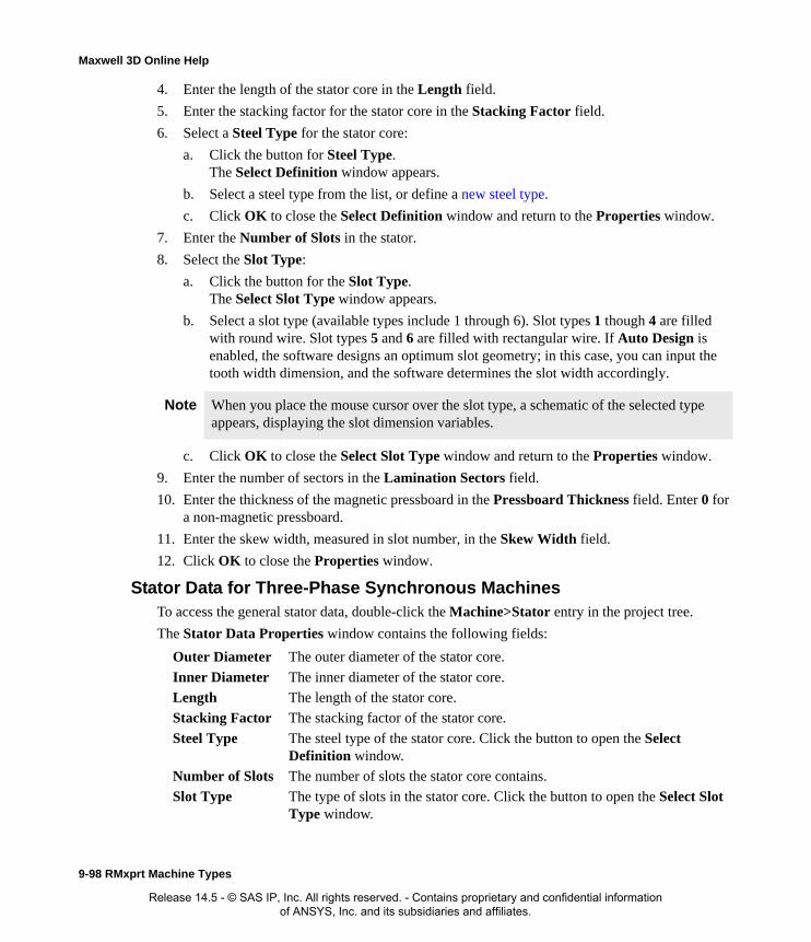
Maxwell 3D Online Help
4. Enter the length of the stator core in the Length field.
5. Enter the stacking factor for the stator core in the Stacking Factor field.
6. Select a Steel Type for the stator core:
a. Click the button for Steel Type.The Select Definition window appears.
b. Select a steel type from the list, or define a new steel type.
c. Click OK to close the Select Definition window and return to the Properties window.
7. Enter the Number of Slots in the stator.
8. Select the Slot Type:
a. Click the button for the Slot Type.The Select Slot Type window appears.
b. Select a slot type (available types include 1 through 6). Slot types 1 though 4 are filled with round wire. Slot types 5 and 6 are filled with rectangular wire. If Auto Design is enabled, the software designs an optimum slot geometry; in this case, you can input the tooth width dimension, and the software determines the slot width accordingly.
c. Click OK to close the Select Slot Type window and return to the Properties window.
9. Enter the number of sectors in the Lamination Sectors field.
10. Enter the thickness of the magnetic pressboard in the Pressboard Thickness field. Enter 0 for a non-magnetic pressboard.
11. Enter the skew width, measured in slot number, in the Skew Width field.
12. Click OK to close the Properties window.
Stator Data for Three-Phase Synchronous MachinesTo access the general stator data, double-click the Machine>Stator entry in the project tree.
The Stator Data Properties window contains the following fields:
Note When you place the mouse cursor over the slot type, a schematic of the selected type appears, displaying the slot dimension variables.
Outer Diameter The outer diameter of the stator core.
Inner Diameter The inner diameter of the stator core.
Length The length of the stator core.
Stacking Factor The stacking factor of the stator core.
Steel Type The steel type of the stator core. Click the button to open the Select Definition window.
Number of Slots The number of slots the stator core contains.
Slot Type The type of slots in the stator core. Click the button to open the Select Slot Type window.
9-98 RMxprt Machine Types
Release 14.5 - © SAS IP, Inc. All rights reserved. - Contains proprietary and confidential information of ANSYS, Inc. and its subsidiaries and affiliates.

Maxwell 3D Online Help
Defining Stator Slots for a Three-Phase Synchronous MachineTo define the slot dimensions:
1. To open the Stator Slot Data Properties window, double-click the Machine-Stator-Slot entry in the project tree on the desktop. (You can also enter values in the Properties section of the desktop without opening a separate window.)
2. Optionally, to automatically design the dimensions of slots Hs2, Bs1, and Bs2, select the Auto Design check box.
3. Optionally, to design dimensions of slots Bs1 and Bs2 based on the stator tooth width, select the Parallel Tooth check box, and enter a value in the Tooth Width field.
4. Enter the available slot dimensions.
5. Click OK to close the Properties window.
Stator Slot Data for Three-Phase Synchronous MachinesTo access the stator slot data, double-click the Machine-Stator-Slot entry in the project tree.
Lamination Sectors
The number of lamination sectors.
Pressboard Thickness
The magnetic press board thickness (0 for a non-magnetic press board).
Skew Width The skew width measured in slot number.
Hs0 Always available.
Hs2 Available only when Auto Design is cleared. When Auto Design is selected, this slot dimension is determined automatically.
Bs0 Always available.
Bs1 Available only when Auto Design and Parallel Tooth are both cleared. When Auto Design is selected, this slot dimension is determined automatically. When Parallel Tooth is selected, this slot dimension is determined based on the value entered in the Tooth Width field.
Bs2 Available only when Auto Design and Parallel Tooth are both cleared. When Auto Design is selected, this slot dimension is determined automatically. When Parallel Tooth is selected, this slot dimension is determined based on the value entered in the Tooth Width field.
RMxprt Machine Types 9-99
Release 14.5 - © SAS IP, Inc. All rights reserved. - Contains proprietary and confidential information of ANSYS, Inc. and its subsidiaries and affiliates.
Maxwell 3D Online Help
The Stator Slot Data Properties window contains the following fields:
Defining Stator Windings and Insulation for a Three-Phase Synchronous
Auto Design Select or clear this to enable or disable auto-design of slots Hs2, Bs1, and Bs2. When this check box is selected, only two other fields appear in the window: Hs0 and Bs0.
Parallel Tooth
Select this to design Bs1 and Bs2 based on the tooth width. When this check box is selected, the Bs1 and Bs2 fields are removed, and the Tooth Width field is added.
Tooth WidthThe tooth width for the parallel tooth, on which Bs1 and Bs2 are designed.
Hs0 A slot dimension (see the diagram shown in the modeling window when Machine-Stator-Slot is selected).
Hs2 A slot dimension (see the diagram shown in the modeling window when Machine-Stator-Slot is selected).
Bs0 A slot dimension (see the diagram shown in the modeling window when Machine-Stator-Slot is selected).
Bs1 A slot dimension (see the diagram shown in the modeling window when Machine-Stator-Slot is selected).
Bs2 A slot dimension (see the diagram shown in the modeling window when Machine-Stator-Slot is selected).
Rs A slot dimension. (see the diagram shown in the modeling window when Machine-Stator-Slot is selected). Rs is added when the slot type is 3 or 4.
9-100 RMxprt Machine Types
Release 14.5 - © SAS IP, Inc. All rights reserved. - Contains proprietary and confidential information of ANSYS, Inc. and its subsidiaries and affiliates.

Maxwell 3D Online Help
MachineUse the Stator Winding window to define the stator winding data, such as the coils, wires, insula-tion, number of parallel branches, and physical dimensions of the windings.
The stator winding data defines the configuration of one phase of the three-phase windings.
To define the stator windings and insulation:
1. To open the Stator Slot Winding Properties window, double-click the Machine-Stator-Winding entry in the project tree on the desktop. (You can also enter values in the Properties section of the desktop without opening a separate window.)
2. Click the Winding tab.
3. Enter the number of layers in the stator winding in the Winding Layers field.
4. Select a Winding Type:
a. Click the button for Winding Type.The Winding Type window appears.
b. Select from one of the following three types of winding:
• Whole Coiled
• Half Coiled
• Editor
End Clearance
End of Stator
Top-End Base-End
End Adjustment
Stator Coil
Inner DiameterInner Radius
RMxprt Machine Types 9-101
Release 14.5 - © SAS IP, Inc. All rights reserved. - Contains proprietary and confidential information of ANSYS, Inc. and its subsidiaries and affiliates.
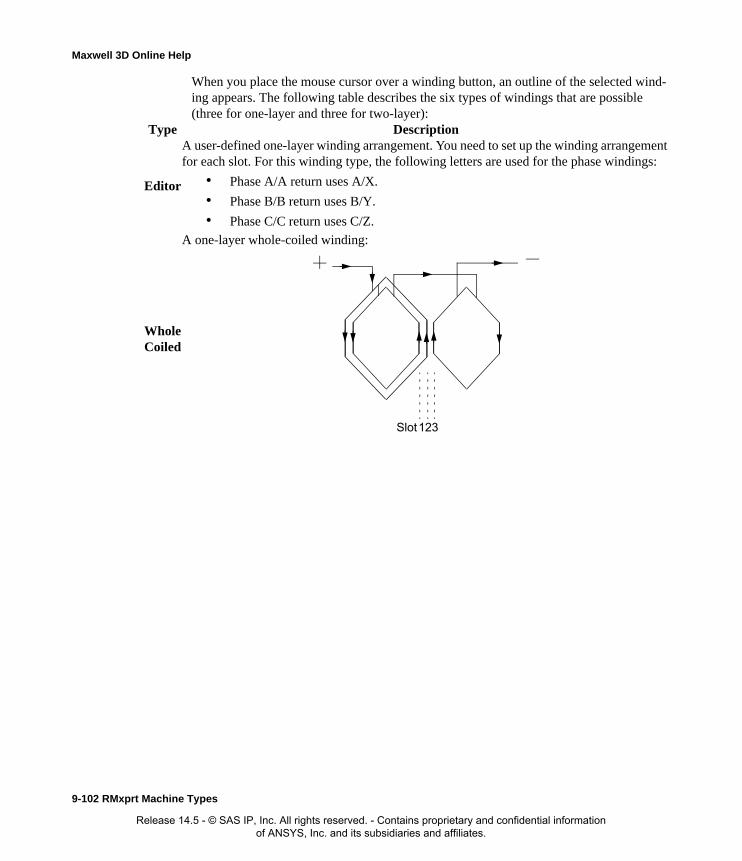
Maxwell 3D Online Help
When you place the mouse cursor over a winding button, an outline of the selected wind-ing appears. The following table describes the six types of windings that are possible (three for one-layer and three for two-layer):
Type Description
Editor
A user-defined one-layer winding arrangement. You need to set up the winding arrangement for each slot. For this winding type, the following letters are used for the phase windings:
• Phase A/A return uses A/X.
• Phase B/B return uses B/Y.
• Phase C/C return uses C/Z.
Whole Coiled
A one-layer whole-coiled winding:
123Slot
9-102 RMxprt Machine Types
Release 14.5 - © SAS IP, Inc. All rights reserved. - Contains proprietary and confidential information of ANSYS, Inc. and its subsidiaries and affiliates.

Maxwell 3D Online Help
Half Coiled
A one-layer concentric half-coiled winding:
EditorA user-defined two-layer winding arrangement. When you select 20, the Winding Editor opens, where you can specify a different winding arrangement for each slot.
Whole Coiled
A two-layer wave winding:
The phase belt for this winding configuration is equal to 360/2m, where m is the phase number.
123Slot
123Slot
RMxprt Machine Types 9-103
Release 14.5 - © SAS IP, Inc. All rights reserved. - Contains proprietary and confidential information of ANSYS, Inc. and its subsidiaries and affiliates.

Maxwell 3D Online Help
c. Once you have clicked a button to select a winding, click OK to close the Winding Type window and return to the Properties window.
5. Select a Winding Type. When you place the mouse cursor over a winding, an outline of the
Half Coiled
A two-layer half-coiled winding:
There is only one coil per phase per pair of poles.
Note Example 1: A one layer winding arranged in 12 slots should be defined as type 10, with the following arrangement: AAZZBBXXCCYY
Example 2: A two layer winding arranged in 12 slots should be defined as type 20, with the following arrangement: AAZZBBXXCCYY
Only the top layer needs to be defined; the bottom layer will be determined according to the coil pitch.
1 2 3Slot
9-104 RMxprt Machine Types
Release 14.5 - © SAS IP, Inc. All rights reserved. - Contains proprietary and confidential information of ANSYS, Inc. and its subsidiaries and affiliates.

Maxwell 3D Online Help
selected winding appears. The following winding types are available:
10 A user-defined single-layer winding arrangement. When you select it, enter the winding arrangement, and choose OK. For this winding type, the following letters are used for the phase windings:
• phase A/A return uses A/X.
• phase B/B return uses B/Y.
• phase C/C return uses C/Z.
11 A one-layer whole-coiled winding:
12 A one-layer concentric half-coiled winding:
20 A user-defined winding arrangement. When you select this type, enter the winding arrangement, and choose OK.
123Slot
123Slot
RMxprt Machine Types 9-105
Release 14.5 - © SAS IP, Inc. All rights reserved. - Contains proprietary and confidential information of ANSYS, Inc. and its subsidiaries and affiliates.
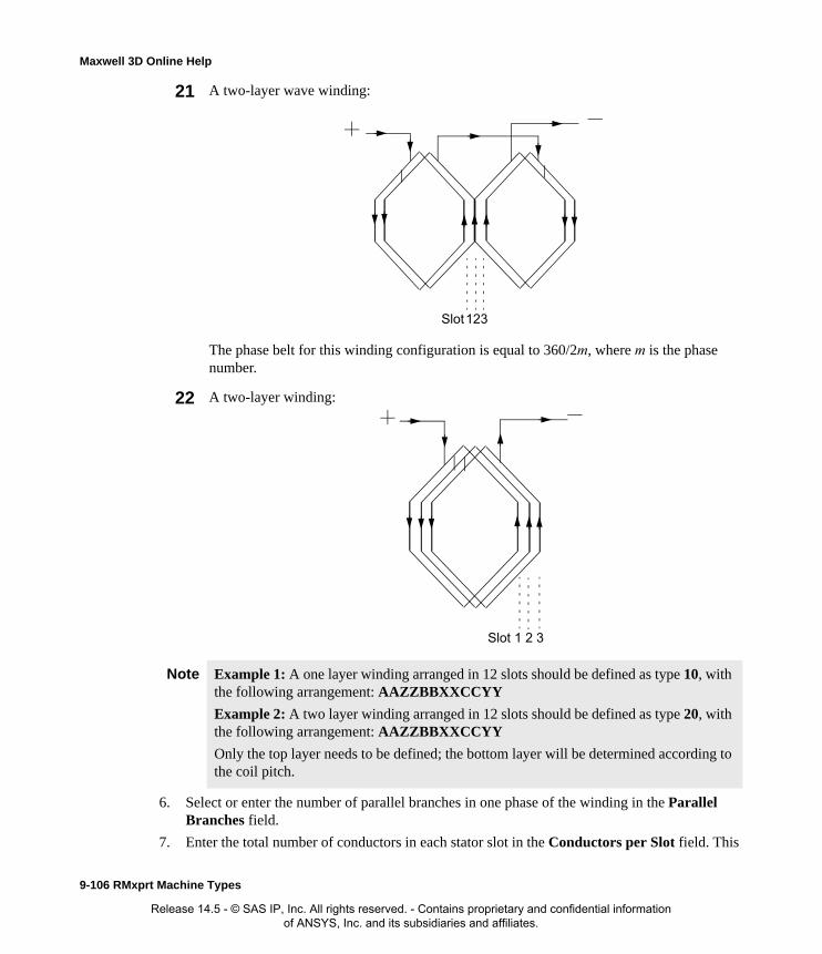
Maxwell 3D Online Help
6. Select or enter the number of parallel branches in one phase of the winding in the Parallel Branches field.
7. Enter the total number of conductors in each stator slot in the Conductors per Slot field. This
21 A two-layer wave winding:
The phase belt for this winding configuration is equal to 360/2m, where m is the phase number.
22 A two-layer winding:
Note Example 1: A one layer winding arranged in 12 slots should be defined as type 10, with the following arrangement: AAZZBBXXCCYY
Example 2: A two layer winding arranged in 12 slots should be defined as type 20, with the following arrangement: AAZZBBXXCCYY
Only the top layer needs to be defined; the bottom layer will be determined according to the coil pitch.
123Slot
1 2 3Slot
9-106 RMxprt Machine Types
Release 14.5 - © SAS IP, Inc. All rights reserved. - Contains proprietary and confidential information of ANSYS, Inc. and its subsidiaries and affiliates.
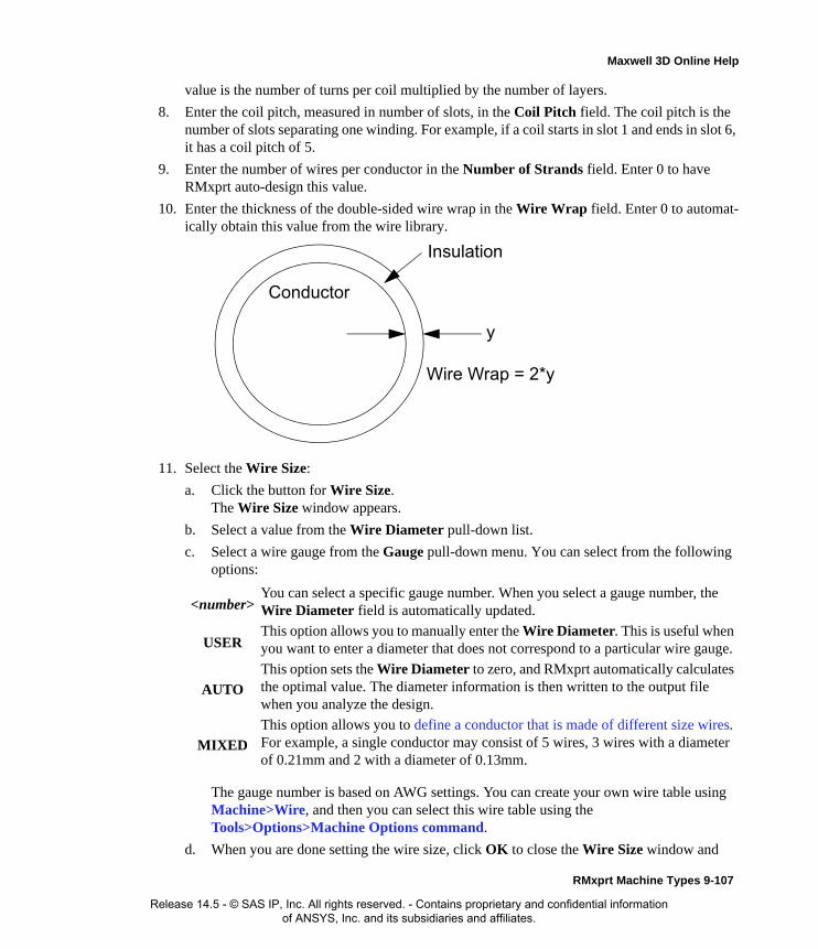
Maxwell 3D Online Help
value is the number of turns per coil multiplied by the number of layers.
8. Enter the coil pitch, measured in number of slots, in the Coil Pitch field. The coil pitch is the number of slots separating one winding. For example, if a coil starts in slot 1 and ends in slot 6, it has a coil pitch of 5.
9. Enter the number of wires per conductor in the Number of Strands field. Enter 0 to have RMxprt auto-design this value.
10. Enter the thickness of the double-sided wire wrap in the Wire Wrap field. Enter 0 to automat-ically obtain this value from the wire library.
11. Select the Wire Size:
a. Click the button for Wire Size.The Wire Size window appears.
b. Select a value from the Wire Diameter pull-down list.
c. Select a wire gauge from the Gauge pull-down menu. You can select from the following options:
The gauge number is based on AWG settings. You can create your own wire table using Machine>Wire, and then you can select this wire table using the Tools>Options>Machine Options command.
d. When you are done setting the wire size, click OK to close the Wire Size window and
<number>You can select a specific gauge number. When you select a gauge number, the Wire Diameter field is automatically updated.
USERThis option allows you to manually enter the Wire Diameter. This is useful when you want to enter a diameter that does not correspond to a particular wire gauge.
AUTO
This option sets the Wire Diameter to zero, and RMxprt automatically calculates the optimal value. The diameter information is then written to the output file when you analyze the design.
MIXED
This option allows you to define a conductor that is made of different size wires. For example, a single conductor may consist of 5 wires, 3 wires with a diameter of 0.21mm and 2 with a diameter of 0.13mm.
Insulation
Conductor
y
Wire Wrap = 2*y
RMxprt Machine Types 9-107
Release 14.5 - © SAS IP, Inc. All rights reserved. - Contains proprietary and confidential information of ANSYS, Inc. and its subsidiaries and affiliates.
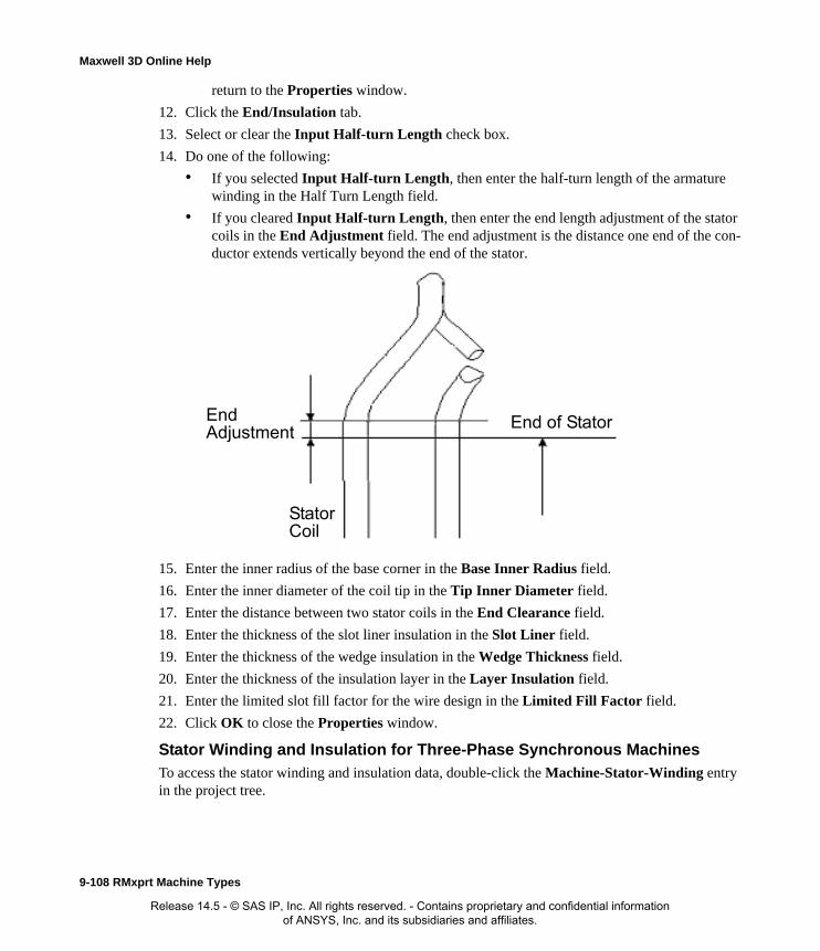
Maxwell 3D Online Help
return to the Properties window.
12. Click the End/Insulation tab.
13. Select or clear the Input Half-turn Length check box.
14. Do one of the following:
• If you selected Input Half-turn Length, then enter the half-turn length of the armature winding in the Half Turn Length field.
• If you cleared Input Half-turn Length, then enter the end length adjustment of the stator coils in the End Adjustment field. The end adjustment is the distance one end of the con-ductor extends vertically beyond the end of the stator.
15. Enter the inner radius of the base corner in the Base Inner Radius field.
16. Enter the inner diameter of the coil tip in the Tip Inner Diameter field.
17. Enter the distance between two stator coils in the End Clearance field.
18. Enter the thickness of the slot liner insulation in the Slot Liner field.
19. Enter the thickness of the wedge insulation in the Wedge Thickness field.
20. Enter the thickness of the insulation layer in the Layer Insulation field.
21. Enter the limited slot fill factor for the wire design in the Limited Fill Factor field.
22. Click OK to close the Properties window.
Stator Winding and Insulation for Three-Phase Synchronous MachinesTo access the stator winding and insulation data, double-click the Machine-Stator-Winding entry in the project tree.
EndAdjustment
StatorCoil
End of Stator
9-108 RMxprt Machine Types
Release 14.5 - © SAS IP, Inc. All rights reserved. - Contains proprietary and confidential information of ANSYS, Inc. and its subsidiaries and affiliates.

Maxwell 3D Online Help
The Stator Winding Data Properties window contains the following fields:
Winding tabWinding Layers The number of winding layers.
Winding Type The type of stator winding. Click the button to open the Winding Type window and choose from Whole Coiled, Half Coiled, and Editor.
Parallel Branches The number of parallel branches in the stator winding.
Conductors per Slot
The number of conductors per stator slot (0 for auto-design).
Coil Pitch The coil pitch measured in number of slots.
Number of Strands
The number of wires per conductor (0 for auto-design).
Wire Wrap The thickness of the double-sided wire wrap (0 to automatically obtain this value from the wire library).
Wire Size The diameter of the wire (0 for auto-design). Click the button to open the Wire Size window where you can specify units, wire type, diameter, and gauge.
End/Insulation tab
Input Half-turn Length7
Select or clear this check box to specify whether or not you want to enter the half-turn length. When this check box is selected, the Half Turn Length field appears the next time you open the Properties window. When this check box is selected, the End Adjustment field appears instead.
Half Turn LengthThe half-turn length of the armature winding.
End Adjustment The end length adjustment of the stator coils, which is the distance one end of the conductor extends vertically beyond the end of the stator.
Base Inner Radius
The inner radius of the base corner.
Tip Inner Diameter
The inner diameter of the coil tip.
End Clearance The end clearance between two adjacent coils.
Slot Liner The thickness of the slot liner insulation.
Wedge Thickness The thickness of the wedge insulation.
RMxprt Machine Types 9-109
Release 14.5 - © SAS IP, Inc. All rights reserved. - Contains proprietary and confidential information of ANSYS, Inc. and its subsidiaries and affiliates.
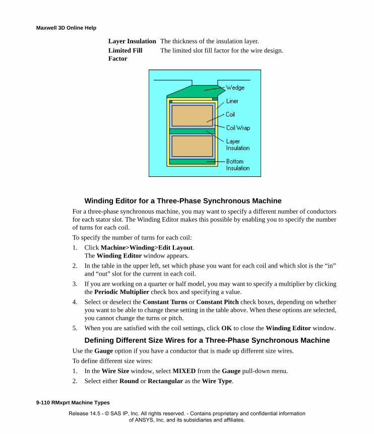
Maxwell 3D Online Help
Winding Editor for a Three-Phase Synchronous MachineFor a three-phase synchronous machine, you may want to specify a different number of conductors for each stator slot. The Winding Editor makes this possible by enabling you to specify the number of turns for each coil.
To specify the number of turns for each coil:
1. Click Machine>Winding>Edit Layout.The Winding Editor window appears.
2. In the table in the upper left, set which phase you want for each coil and which slot is the “in” and “out” slot for the current in each coil.
3. If you are working on a quarter or half model, you may want to specify a multiplier by clicking the Periodic Multiplier check box and specifying a value.
4. Select or deselect the Constant Turns or Constant Pitch check boxes, depending on whether you want to be able to change these setting in the table above. When these options are selected, you cannot change the turns or pitch.
5. When you are satisfied with the coil settings, click OK to close the Winding Editor window.
Defining Different Size Wires for a Three-Phase Synchronous MachineUse the Gauge option if you have a conductor that is made up different size wires.
To define different size wires:
1. In the Wire Size window, select MIXED from the Gauge pull-down menu.
2. Select either Round or Rectangular as the Wire Type.
Layer Insulation The thickness of the insulation layer.
Limited Fill Factor
The limited slot fill factor for the wire design.
9-110 RMxprt Machine Types
Release 14.5 - © SAS IP, Inc. All rights reserved. - Contains proprietary and confidential information of ANSYS, Inc. and its subsidiaries and affiliates.

Maxwell 3D Online Help
3. Enter the appropriate wire data in the table:
• For a round wire:
• Enter the Diameter in the table.
• Enter a Number in the table to specify how many of the conductor’s wires have this diameter.
• For a rectangular wire:
• Enter the Width of the wire in the table.
• Enter the Thickness of the wire in the table.
• Enter the Fillet value in the table.
• Enter a Number in the table to specify how many of the conductor’s wires have this data.
4. Choose Add to add the new wire data.
5. Repeat steps 3 and 4 for each size wire you want to add.
6. When you are finished defining the wires, click OK to close the Wire Size window.
Stator Vent Data for Three-Phase Synchronous Machines
To insert a vent on a stator for a three phase synchronous machine:
1. Right click on the stator icon in the project tree to display the shortcut menu.
2. Click Insert Vent.
The vent icon appears in the project tree under the stator.
To remove an existing vent item,
1. Right-click on the stator icon in the project tree to display the shortcut menu.
2. Click Remove Vent.
This removes the vent item from the project tree.
To access the Vent properties for a vent, double click on a vent item. The Vent Properties window contains the following fields.
Note For example, if one conductor is made up of 5 wires, and 3 of those wires have a diameter of 0.21mm, and the other 2 have a diameter of 0.13mm, then the mixed wire size table will have two lines. The first line will list Diameter = 0.21 and Number = 3. The second line will list Diameter = 0.13 and Number = 2. An equivalent wire diameter is displayed as Wire Size value in the Winding tab in the Properties window.
Vent Ducts The number of radial vent ducts.
Duct Width The width of the radial vent ducts.
Magnetic spacer width
Width of magnetic spacer which holds vent ducts. O for non-magnetic spacer.
Duct pitch. Center-to-Center distance between two adjacent Vent ducts
RMxprt Machine Types 9-111
Release 14.5 - © SAS IP, Inc. All rights reserved. - Contains proprietary and confidential information of ANSYS, Inc. and its subsidiaries and affiliates.

Maxwell 3D Online Help
Defining the Rotor for a Three-Phase Synchronous MachineThe rotor consists of copper bars in which current is induced by the magnetic fields produced by the stator windings. In the project tree, double-click Machine-Rotor and Machine-Rotor-Wind-ing to define the rotor.
To define the general rotor data:
1. To open the Rotor Data Properties window, double-click the Machine-Rotor entry in the project tree on the desktop. (You can also enter values in the Properties section of the desktop without opening a separate window.)
2. Click the Rotor tab.
3. Enter the outer diameter of the rotor in the Outer Diameter field.
4. Enter the inner diameter of the rotor in the Inner Diameter field.
5. Enter the length of the rotor core in the Length field.
6. Select a Steel Type for the rotor core:
a. Click the button for Steel Type.The Select Definition window appears.
b. Select a steel type from the list, or define a new steel type.
c. Click OK to close the Select Definition window and return to the Properties window.
7. Enter the stacking factor for the rotor core in the Stacking Factor field.
8. Click the Pole tab.
9. Enter the pole-arc center offset from the rotor center in the Pole Arc Offset field.
Offset
Radius
9-112 RMxprt Machine Types
Release 14.5 - © SAS IP, Inc. All rights reserved. - Contains proprietary and confidential information of ANSYS, Inc. and its subsidiaries and affiliates.

Maxwell 3D Online Help
10. Enter the width of the pole shoe in the Pole Shoe Width field.
11. Enter the height of the pole shoe in the Pole Shoe Height field.
12. Enter the width of the pole body in the Pole Body Width field.
13. Enter the height of the pole body in the Pole Body Height field.
14. Enter the width between the rotor pole and rotor yoke in the Second Air Gap field.
15. To include the two arcs in the half-pole range, do the following:
a. Select the Select Pole Arc check box.
b. Enter the offset of the second arc perpendicular to the pole-center line in the Off2_x field.
c. Enter the offset of the second arc parallel with the pole-center line in the Off2_y field.
16. Select or clear the Magnetic PressBoard check box to specify whether or not the press board is made of magnetic material.
17. Enter the thickness of the press board in the Press Board Thickness field.
18. Click the Insulation tab.
19. Enter the thickness of the insulating material beneath the shoe pole in the Shoe Insulation field.
20. Enter the thickness of the insulating material on the side of the pole body in the Pole Insula-tion field.
21. Enter the clearance distance between the windings in the Winding Clearance field.
22. Click OK to close the Properties window.
Rotor, Rotor Pole, and Insulation for Three-Phase Synchronous Machines
To access the general rotor data, pole data, and insulation data double-click the Machine>Rotor entry in the project tree.
The Rotor Data Properties window contains the following fields:
Rotor tab Outer Diameter The outer diameter of the rotor core.
Inner Diameter The inner diameter of the rotor core.
Length The length of the rotor core.
Steel Type The steel type of the rotor core. Click the button to open the Select Definition window.
Stacking Factor The stacking factor of the rotor core.
Pole tab Pole Arc Offset The pole-arc center offset from the rotor center.
Pole Shoe Width The width of the pole shoe.
Pole Shoe Height The height of the pole shoe.
Pole Body Width The width of the pole body.
Pole Body Height The height of the pole body.
Second Air Gap The width of the second air gap, between the rotor pole and rotor yoke.
RMxprt Machine Types 9-113
Release 14.5 - © SAS IP, Inc. All rights reserved. - Contains proprietary and confidential information of ANSYS, Inc. and its subsidiaries and affiliates.

Maxwell 3D Online Help
Defining the Rotor Pole for a Three-Phase Synchronous MachineThe rotor pole drives the electromagnetic field that is coupled with the stator windings.
The following figure shows a partial diagram of a rotor pole:
Second Pole Arc Select or clear this option to specify whether or not the pole surface includes the two arcs in the half-pole range. When you select this check box, two additional fields appear: Off2_x and Off2_y.
Off2_x The offset of the second arc perpendicular to the pole-center line. This field is only available when Second Pole Arc is selected.
Off2_y The offset of the second arc parallel with the pole-center line. This field is only available when Second Pole Arc is selected.
Magnetic PressBoard
Select or clear this option to specify whether or not the press board is made of magnetic material.
Press Board Thickness
The thickness of the press board.
Steel Type The steel type of the rotor pole. Click the button to open the Select Definition window. Default value is the same as the rotor core.
Stacking Factor The stacking factor of the rotor pole. Default value is the same as the rotor core.
Insulation tab
Shoe Insulation The thickness of the insulating material beneath the pole shoe.
Pole Insulation The thickness of the insulating material on the side of the pole body.
Winding Clearance
The clearance distance between the windings.
9-114 RMxprt Machine Types
Release 14.5 - © SAS IP, Inc. All rights reserved. - Contains proprietary and confidential information of ANSYS, Inc. and its subsidiaries and affiliates.

Maxwell 3D Online Help
The following figure shows a diagram of an entire rotor:
Defining the Rotor Winding Data for a Three-Phase Synchronous MachineUse the Rotor Winding window to define the wires and physical dimensions of the rotor winding. The rotor winding provides the excitation for the electromagnetic field that produces the rotor pole.
Slot pitch
Centerslot pitch
Overallheight
Second air-gap
Wire thickness
Wirewidth
Pole bodywidth
Pole shoe width
Poleinsulation
Shoeinsulation
RMxprt Machine Types 9-115
Release 14.5 - © SAS IP, Inc. All rights reserved. - Contains proprietary and confidential information of ANSYS, Inc. and its subsidiaries and affiliates.

Maxwell 3D Online Help
To define the rotor windings:
1. To open the Rotor Winding Properties window, double-click the Machine-Rotor-Winding entry in the project tree on the desktop. (You can also enter values in the Properties section of the desktop without opening a separate window.)
2. Select the Winding Type for the rotor:
a. Click the button.The Winding Type window appears.
b. Click to select the type of winding, from Round, Cylinder, or EdgeWise.When you place the mouse cursor over the winding type, a schematic of the selected wind-ing appears
c. Click OK to return to the Properties window.
3. Enter the number of parallel branches for the winding in the Parallel Branches field.
4. Conductors per Pole
5. Enter the number of wires in each conductor in the Number of Strands field.
6. Enter the width of the insulating wire wrap in the Wire Wrap field.
7. Interturn Insulation
8. Enter the gauge of the wire in the Wire Size field.
9. Enter the Axial Clearance to specify the axial distance between the core and the coil at the end of the lamination stack.
10. Limited Cross Width
11. Limited Cross Height
12. Winding Fillet
13. Click OK to close the Properties window.
Rotor
Winding
RadialDuct Width
FilletAxialClearance
length
Rotorwinding
9-116 RMxprt Machine Types
Release 14.5 - © SAS IP, Inc. All rights reserved. - Contains proprietary and confidential information of ANSYS, Inc. and its subsidiaries and affiliates.

Maxwell 3D Online Help
Rotor Winding Data for Three-Phase Synchronous Machines
To access the rotor winding data, double-click the Machine-Rotor-Winding entry in the project tree.
The Rotor Winding Data Properties window contains the following fields:
Defining the Rotor Damper DataTo define a rotor damper for a machine that permits one:
1. Click Machine>Insert Damper.
The Damper icon appears in the project tree under the rotor icon. A slot icon appears in the hierarchy under the damper.
2. Double click on the Damper icon to display the properties window for the damper.
3. Enter the appropriate values for the damper. The slot type, the bar conductor type, and end conductor type are entered by clicking on buttons that open other windows.
4. Click OK to close the properties window.
Damper Data for Three-Phase Synchronous Machines
By option, you can add a damper to or remove damper from the rotor of a three phase machine.
Winding Type The type of rotor winding. Click the button to open the Winding Type window and choose from Whole Coiled, Half Coiled, and Editor.
Parallel Branches The number of parallel branches in the rotor winding.
Conductors per Pole
The number of conductors per rotor pole (0 for auto-design).
Number of Strands
The number of wires per conductor (0 for auto-design).
Wire Wrap The thickness of the double-sided wire wrap (0 to automatically obtain this value from the wire library).
Interturn Insulation
The thickness of the inter-turn insulation of an edgewise winding. This field only appears when EdgewiseCoil is selected as the Winding Type.
Wire Size The diameter of the wire (0 for auto-design). Click the button to open the Wire Size window where you can specify units, wire type, diameter, and gauge.
Axial Clearance The axial gap between the field winding and the pole body or inner coil.
Limited Cross Width
The limited cross-section width for the winding design or arrangement (0 for available maximum area).
Limited Cross Height
The limited cross-section height for the winding design or arrangement (0 for available maximum area).
Winding Fillet The size of the winding fillet.
RMxprt Machine Types 9-117
Release 14.5 - © SAS IP, Inc. All rights reserved. - Contains proprietary and confidential information of ANSYS, Inc. and its subsidiaries and affiliates.

Maxwell 3D Online Help
To add a damper:
1. Right-click on the rotor icon in the project tree to display the short cut menu.
2. Click Insert Damper on the menu.
The damper appears in the project tree under the rotor. The damper also includes an associated slot.
1. To remove a damper, right-click on the rotor icon in the project tree to display the short cut menu.
2. Click Remove Damper on the menu.
The damper and associated slot are removed from the project tree.
The damper data contains the following fields.
Defining the Shaft Data for a Three-Phase Synchronous Machine
To define the shaft:
1. To open the Shaft Data Properties window, double-click the Machine>Shaft entry in the project tree on the desktop. (You can also enter values in the Properties section of the desktop without opening a separate window.)
2. Select or clear the Magnetic Shaft check box to specify whether or not the shaft is to be made
Damper slots per pole
Number of damper slots per pole.
Slot type Damper slot type. Specify this by clicking the button in the properties field and selecting from the Select Slot Type window.
Cast Rotor. Whether the rotor squirrel cage winding is cast.
Bar conductor type.
Specify this by clicking the button in the properties field, and using the Select Definition window to find and assign materials.
End length Single side end extended bar length/
End ring width Axial width of end ring.
End ring height Radial height of end ring.
End ring conductor type.
Specify this by clicking the button in the properties field and using the Select Definition window to find and assign the material.
Slot pitch Slot pitch in mechanical degrees.
Center slot pitch Center slot pitch in mechanical degrees
End Ring type Type of end ring for the damper. Specify this by clicking the button in the properties field and use the Select Pole type window to select from the available types.
9-118 RMxprt Machine Types
Release 14.5 - © SAS IP, Inc. All rights reserved. - Contains proprietary and confidential information of ANSYS, Inc. and its subsidiaries and affiliates.
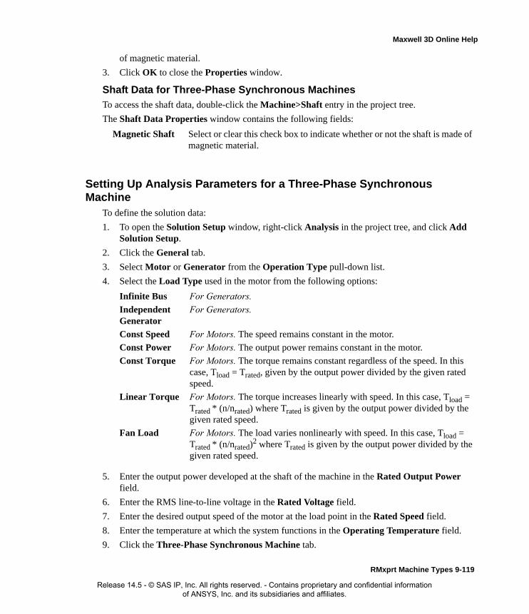
Maxwell 3D Online Help
of magnetic material.
3. Click OK to close the Properties window.
Shaft Data for Three-Phase Synchronous Machines
To access the shaft data, double-click the Machine>Shaft entry in the project tree.
The Shaft Data Properties window contains the following fields:
Setting Up Analysis Parameters for a Three-Phase Synchronous Machine
To define the solution data:
1. To open the Solution Setup window, right-click Analysis in the project tree, and click Add Solution Setup.
2. Click the General tab.
3. Select Motor or Generator from the Operation Type pull-down list.
4. Select the Load Type used in the motor from the following options:
5. Enter the output power developed at the shaft of the machine in the Rated Output Power field.
6. Enter the RMS line-to-line voltage in the Rated Voltage field.
7. Enter the desired output speed of the motor at the load point in the Rated Speed field.
8. Enter the temperature at which the system functions in the Operating Temperature field.
9. Click the Three-Phase Synchronous Machine tab.
Magnetic Shaft Select or clear this check box to indicate whether or not the shaft is made of magnetic material.
Infinite Bus For Generators.
Independent Generator
For Generators.
Const Speed For Motors. The speed remains constant in the motor.
Const Power For Motors. The output power remains constant in the motor.
Const Torque For Motors. The torque remains constant regardless of the speed. In this case, Tload = Trated, given by the output power divided by the given rated speed.
Linear Torque For Motors. The torque increases linearly with speed. In this case, Tload = Trated * (n/nrated) where Trated is given by the output power divided by the given rated speed.
Fan Load For Motors. The load varies nonlinearly with speed. In this case, Tload = Trated * (n/nrated)2 where Trated is given by the output power divided by the given rated speed.
RMxprt Machine Types 9-119
Release 14.5 - © SAS IP, Inc. All rights reserved. - Contains proprietary and confidential information of ANSYS, Inc. and its subsidiaries and affiliates.

Maxwell 3D Online Help
10. Enter a value in the Rated Power Factor field.
11. Select Wye or Delta from the Winding Connection pull-down list.
12. In the Exciter Efficiency field, enter the efficiency of the exciter used to supply the rotor winding with DC current if it is mechanically connected to the shaft of the generator. The effi-ciency value ranges between 0 and 1 and will only affect the total efficiency result.
13. To enter an Input Exciting Current, select the check box, enter a value, and select the units.
14. Click OK to close the Solution Setup window.
Related Topics:
Solution Data for Three-Phase Synchronous Machines
Solution Data for Three-Phase Synchronous Machines
To access the solution data, right-click Analysis in the project tree, and click Add Solution Setup.
The Solution Setup window contains the following fields:
Related Topics:
Setting Up Analysis Parameters for a Three-Phase Synchronous Machine
Operation Type On the General tab. Select from Motor or Generator.
Load Type On the General tab. For a motor, select from Const Speed, Const Power, Const Torque, Linear Torque, and Fan Load. The default is Const Power. For a generator, select from Infinite Bus and Independent Generator.
Rated Output Power
On the General tab. Type a value for the rated output voltage, and select the units.
Rated Voltage On the General tab. Type a value for the rated voltage, and select the units.
Rated Speed On the General tab. Type a value for the rated speed, and select the units.
Operating Temperature
On the General tab. Type a value for the operating temperature, and select the units.
Rated Power Factor
On the Three-Phase Synchronous Machine tab. Type a value for the rated power factor.
Winding Connection
On the Three-Phase Synchronous Machine tab. Select from Wye or Delta.
Exciter Efficiency On the Three-Phase Synchronous Machine tab. Type a percent for the exciter efficiency.
Input Exciting Current
On the Three-Phase Synchronous Machine tab. If you select this check box, then enter the exciting current, and select the units.
9-120 RMxprt Machine Types
Release 14.5 - © SAS IP, Inc. All rights reserved. - Contains proprietary and confidential information of ANSYS, Inc. and its subsidiaries and affiliates.

Maxwell 3D Online Help
Brushless Permanent-Magnet DC MotorsAfter you have selected Brushless Permanent-Magnet DC Motors as your model type, you need to define the following:
• General data, such as the voltage, speed, and circuit type of the model.
• Circuit data, such as lead trigger angle, transistor drop, and control circuit information.
• Stator data, such as the diameter, slot dimensions, winding data, and skew width of the stator.
• Rotor data
• Rotor pole data, such as the magnet dimensions and stacking factor.
• Shaft data
• Solution data, such as rated output voltage and frequency.
Analysis Approach for Brushless PMDC MotorsThe stator of a brushless DC motor is equipped with a polyphase winding. The phases are con-nected to the DC bus through a switching circuit. The switching sequence is controlled so that it is synchronized with the position of the rotor. As a result, the stator produces a rotating magnetic field.
The rotor is equipped with permanent magnets, creating a structure with the same number of poles at the stator. The stator switches act like a commutator in a classic DC motor.
In brushless permanent-magnet DC (BLDC) motors, the armature currents are commutated exactly according to rotor position. The signal of rotor position may be obtained from a position sensor, or from induced voltages for sensor-less control system.
The performance of BLDC motors is analyzed via a time-domain simulation. The voltage equation in the time domain is:
where R1, Ld, Lq, and L0 are armature resistance, d-axis synchronous inductance, q-axis synchro-nous inductance, and 0-axis inductance, respectively. e is rotor speed in electrical rad/s, and represents for d/dt. The transformations for terminal voltages, induced voltages, and winding currents are given by the following three equations:
vd
vq
v0
ed
eq
e0
–
R1 Ldp+ Lqωe– 0
Ldωe– R1 Lqp+ 0
0 0 R1 L0p+
id
iq
i0
⋅=
ω ρ
RMxprt Machine Types 9-121
Release 14.5 - © SAS IP, Inc. All rights reserved. - Contains proprietary and confidential information of ANSYS, Inc. and its subsidiaries and affiliates.

Maxwell 3D Online Help
The transformation matrices for 2-phase, 3-phase, and 4-phases systems, noted as C2, C3, and C4, are as follows:
where = 2 /3.
The input power (electric power) can now be computed from the voltage and current as:
The output power (mechanical power) is:
P2 = P1 - (Pfw + PCua + Pt + PFe)where Pfw, PCua, Pt, and PFe are frictional and wind loss, armature copper loss, transistor/diode loss, and iron-core loss, respectively.
vd
vq
v0
CT
va
vb⋅=
ed
eq
e0
CT
ea
eb⋅=
ia
ibC
id
iq
i0
⋅=
C2θcos θsin 0
θsin θcos 0=
C323---
θcos θsin 1 2( )⁄
θ α–( )cos θ α–( )sin 1 2( )⁄
θ 2α–( )cos θ 2α–( )sin 1 2( )⁄
=
C4
θcos θsin 0
θsin θcos– 0
θcos– θsin– 0
θsin– θcos 0
=
α π
p11t--- vdid vqiq v0i0+ +( ) td
0
T
=
9-122 RMxprt Machine Types
Release 14.5 - © SAS IP, Inc. All rights reserved. - Contains proprietary and confidential information of ANSYS, Inc. and its subsidiaries and affiliates.

Maxwell 3D Online Help
The output mechanical shaft torque T2 is:
T2 = P2 /
where is the rotor speed in mechanical rad/s.
The efficiency is computed by:
eff = P2/P1 * 100%
Defining a Brushless Permanent-Magnet DC MotorThe general procedure for defining a brushless permanent-magnet DC motor is as follows:
1. Insert the permanent magnet brushless DC motor into a new or existing project.
2. Double-click the Machine entry in the project tree to define the general data.
3. Double-click the Machine-Circuit entry in the project tree to define the control circuit.
4. Double-click the Machine-Stator entry in the project tree to define the stator geometry.
5. Double-click the Machine-Stator-Slot entry in the project tree to define the stator slot dimen-sions.
6. Double-click the Machine-Stator-Winding entry in the project tree to define the stator wind-ings and conductors.
7. Double-click the Machine-Rotor entry in the project tree to define the rotor geometry.
8. Double-click the Machine-Rotor-Pole entry in the project tree to define the pole, embrace, offset, and air gap data for the rotor pole.
9. Double-click the Machine-Shaft entry in the project tree to define the magnetism of the shaft.
10. Right-click Analysis in the project tree, and click Add Solution Setup to define the solution data.
11. Choose File>Save to save the project.
12. Choose RMxprt>Analyze to analyze the design.
Once analyzed, the model can be viewed in the Maxwell 2D Modeler, or it can be used to create a new Maxwell 2D project, and a new Maxwell 3D design
Please refer to the Brushless Permanent-Magnet DC Motor Problem application note, on the tech-nical support page of the ANSYS web site, for a specific example of a brushless permanent-magnet DC motor problem.
Defining the General Data for a Brushless PMDC Motor
Use the General window to specify the rated output power, voltage values, circuit type, and speed of the brushless DC motor.
To define the general data:
1. To open the General Data Properties window, double-click the Machine entry in the project tree on the desktop. (You can also enter values in the Properties section of the desktop without
Note When you place the cursor over an entry field in the data windows, a brief description of that field appears in the status bar at the bottom of the RMxprt window.
ω
ω
RMxprt Machine Types 9-123
Release 14.5 - © SAS IP, Inc. All rights reserved. - Contains proprietary and confidential information of ANSYS, Inc. and its subsidiaries and affiliates.

Maxwell 3D Online Help
opening a separate window.)
2. Enter the number of poles for the machine in the Number of Poles field. This value is the total number of poles in the stator (or the number of pole pairs multiplied by two).
3. Enter the energy loss due to friction at the given speed in the Frictional Loss field.
4. Enter the wind loss due to air resistance measured at the reference speed in the Wind Loss field.
5. Enter the given speed in the Reference Speed field.
6. Select DC or CCC from the Control Type pull-down list.
7. Select a Circuit Type from the following types:
The circuit types are based on industry standards. By default, type Y3, a three-phase, six-status circuit, is selected as the circuit type.
8. Click OK to close the Properties window.
General Data for Brushless PMDC MotorsTo access the general data, double-click the Machine entry in the project tree.
The General Data Properties window for a three-phase induction motor contains the following fields:
Y3 Y-connected, three-phase.
L3 Loop-type, three-phase.
S3 Star-type, three-phase.
C2 Cross-type, two-phase.
L4 Loop-type, four-phase.
S4 Star-type, four-phase.
Note When you place the mouse cursor over a circuit type, an outline schematic of the circuit appears.
Machine Type The machine type you selected when inserting a new RMxprt design (Brushless Permanent-Magnet DC Motor).
Number of Poles The number of poles the machine contains.
Rotor Position Select whether the rotor is an Inner Rotor or Outer Rotor.
Frictional Loss The frictional energy loss (due to friction) measured at the reference speed.
Wind Loss The wind loss (due to air resistance) measured at the reference speed.
9-124 RMxprt Machine Types
Release 14.5 - © SAS IP, Inc. All rights reserved. - Contains proprietary and confidential information of ANSYS, Inc. and its subsidiaries and affiliates.
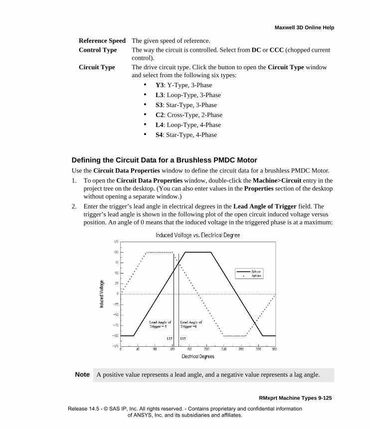
Maxwell 3D Online Help
Defining the Circuit Data for a Brushless PMDC Motor
Use the Circuit Data Properties window to define the circuit data for a brushless PMDC Motor.
1. To open the Circuit Data Properties window, double-click the Machine>Circuit entry in the project tree on the desktop. (You can also enter values in the Properties section of the desktop without opening a separate window.)
2. Enter the trigger’s lead angle in electrical degrees in the Lead Angle of Trigger field. The trigger’s lead angle is shown in the following plot of the open circuit induced voltage versus position. An angle of 0 means that the induced voltage in the triggered phase is at a maximum:
Reference Speed The given speed of reference.
Control Type The way the circuit is controlled. Select from DC or CCC (chopped current control).
Circuit Type The drive circuit type. Click the button to open the Circuit Type window and select from the following six types:
• Y3: Y-Type, 3-Phase
• L3: Loop-Type, 3-Phase
• S3: Star-Type, 3-Phase
• C2: Cross-Type, 2-Phase
• L4: Loop-Type, 4-Phase
• S4: Star-Type, 4-Phase
Note A positive value represents a lead angle, and a negative value represents a lag angle.
RMxprt Machine Types 9-125
Release 14.5 - © SAS IP, Inc. All rights reserved. - Contains proprietary and confidential information of ANSYS, Inc. and its subsidiaries and affiliates.

Maxwell 3D Online Help
3. Enter the period from on-status to off-status of a transistor, in electrical degrees, in the Trigger Pulse Width field.
4. Enter the voltage drop across one transistor when the transistor is turned on in the Transistor Drop field. Refer to the figures of the different circuit types in step 2.
5. Enter the voltage drop of one diode in the discharge loop in the Diode Drop field. If you selected a star-type circuit (S3 or S4) as the Circuit Type, enter the total discharge voltage in this field.
6. If you selected CCC (chopped current control) as the Control Type, then enter the maximum and minimum current values in the Maximum Current and Minimum Current fields.
7. Click OK to close the Properties window.
Circuit Data for Brushless PMDC Motors
To access the Circuit Data Properties window, double-click the Machine>Circuit entry in the project tree.
Defining the Stator Data for a Brushless PMDC Motor
The stator is the outer lamination stack where the polyphase voltage windings reside.
To define the general stator data:
1. To open the Stator Data Properties window, double-click the Machine>Stator entry in the project tree on the desktop. (You can also enter values in the Properties section of the desktop without opening a separate window.)
2. Enter the Outer Diameter of the stator.
3. Enter the Inner Diameter of the stator.
4. Enter the length of the stator core in the Length field.
5. Enter the stacking factor for the stator core in the Stacking Factor field.
6. Select a Steel Type for the stator core:
a. Click the button for Steel Type.The Select Definition window appears.
Lead Angle of Trigger
The trigger’s lead angle, in electrical degrees.
Trigger Pulse Width
The period from on-status to off-status for a transistor, in electrical degrees.
Transistor Drop The voltage drop across one transistor when the transistor is turned on.
Diode Drop The voltage drop across one diode in the discharge loop.
Maximum Current
The maximum current for the chopped current control. This field is not available for a DC circuit.
Minimum Current
The minimum current for the chopped current control. This field is not available for a DC circuit.
9-126 RMxprt Machine Types
Release 14.5 - © SAS IP, Inc. All rights reserved. - Contains proprietary and confidential information of ANSYS, Inc. and its subsidiaries and affiliates.
Maxwell 3D Online Help
b. Select a steel type from the list, or define a new steel type.
c. Click OK to close the Select Definition window and return to the Properties window.
7. Enter the Number of Slots in the stator.
8. Select the Slot Type:
a. Click the button for the Slot Type.The Select Slot Type window appears.
b. Select a slot type (available types include 1 through 4).
c. Click OK to close the Select Slot Type window and return to the Properties window.
9. Enter the skew width, measured in slot number, in the Skew Width field.
10. Click OK to close the Properties window.
Stator Data for Brushless PMDC Motors
To access the general stator data, double-click the Machine>Stator entry in the project tree.
The Stator Data Properties window contains the following fields:
Defining the Stator Slots for a Brushless PMDC MotorTo define the physical dimensions of the stator slots:
1. To open the Stator Slot Data Properties window, double-click the Machine-Stator-Slot entry in the project tree on the desktop. (You can also enter values in the Properties section of the desktop without opening a separate window.)
2. Optionally, to automatically design the dimensions of slots Hs2, Bs1, and Bs2, select the Auto Design check box.
3. Optionally, to design dimensions of slots Bs1 and Bs2 based on the stator tooth width, select the Parallel Tooth check box, and enter a value in the Tooth Width field.
Note When you place the mouse cursor over the slot type, a schematic of the selected type appears, displaying the slot dimension variables.
Outer Diameter The outer diameter of the stator core.
Inner Diameter The inner diameter of the stator core.
Length The length of the stator core.
Stacking Factor The stacking factor of the stator core.
Steel Type The steel type of the stator core. Click the button to open the Select Definition window.
Number of Slots The number of slots the stator core contains.
Slot Type The type of slots in the stator core. Click the button to open the Select Slot Type window.
Skew Width The skew width measured in slot number.
RMxprt Machine Types 9-127
Release 14.5 - © SAS IP, Inc. All rights reserved. - Contains proprietary and confidential information of ANSYS, Inc. and its subsidiaries and affiliates.

Maxwell 3D Online Help
4. Enter the available slot dimensions.
5. Click OK to close the Properties window.
Stator Slot Data for Brushless PMDC MotorsTo access the stator slot data, double-click the Machine-Stator-Slot entry in the project tree.
The Stator Slot Data Properties window contains the following fields:
Hs0 Always available.
Hs2 Available only when Auto Design is cleared. When Auto Design is selected, this slot dimension is determined automatically.
Bs0 Always available.
Bs1 Available only when Auto Design and Parallel Tooth are both cleared. When Auto Design is selected, this slot dimension is determined automatically. When Parallel Tooth is selected, this slot dimension is determined based on the value entered in the Tooth Width field.
Bs2 Available only when Auto Design and Parallel Tooth are both cleared. When Auto Design is selected, this slot dimension is determined automatically. When Parallel Tooth is selected, this slot dimension is determined based on the value entered in the Tooth Width field.
Auto Design Select or clear this to enable or disable auto-design of slots Hs2, Bs1, and Bs2. When this check box is selected, only two other fields appear in the window: Hs0 and Bs0.
Parallel Tooth
Select this to design Bs1 and Bs2 based on the tooth width. When this check box is selected, the Bs1 and Bs2 fields are removed, and the Tooth Width field is added.
Tooth WidthThe tooth width for the parallel tooth, on which Bs1 and Bs2 are designed.
Hs0 A slot dimension (see the diagram shown in the modeling window when Machine-Stator-Slot is selected).
Hs1 A slot dimension (see the diagram shown in the modeling window when Machine-Stator-Slot is selected).
Hs2 A slot dimension (see the diagram shown in the modeling window when Machine-Stator-Slot is selected).
Bs0 A slot dimension (see the diagram shown in the modeling window when Machine-Stator-Slot is selected).
Bs1 A slot dimension (see the diagram shown in the modeling window when Machine-Stator-Slot is selected).
Bs2 A slot dimension (see the diagram shown in the modeling window when Machine-Stator-Slot is selected).
Rs A slot dimension. (see the diagram shown in the modeling window when Machine-Stator-Slot is selected). Rs is added when the slot type is 3 or 4.
9-128 RMxprt Machine Types
Release 14.5 - © SAS IP, Inc. All rights reserved. - Contains proprietary and confidential information of ANSYS, Inc. and its subsidiaries and affiliates.
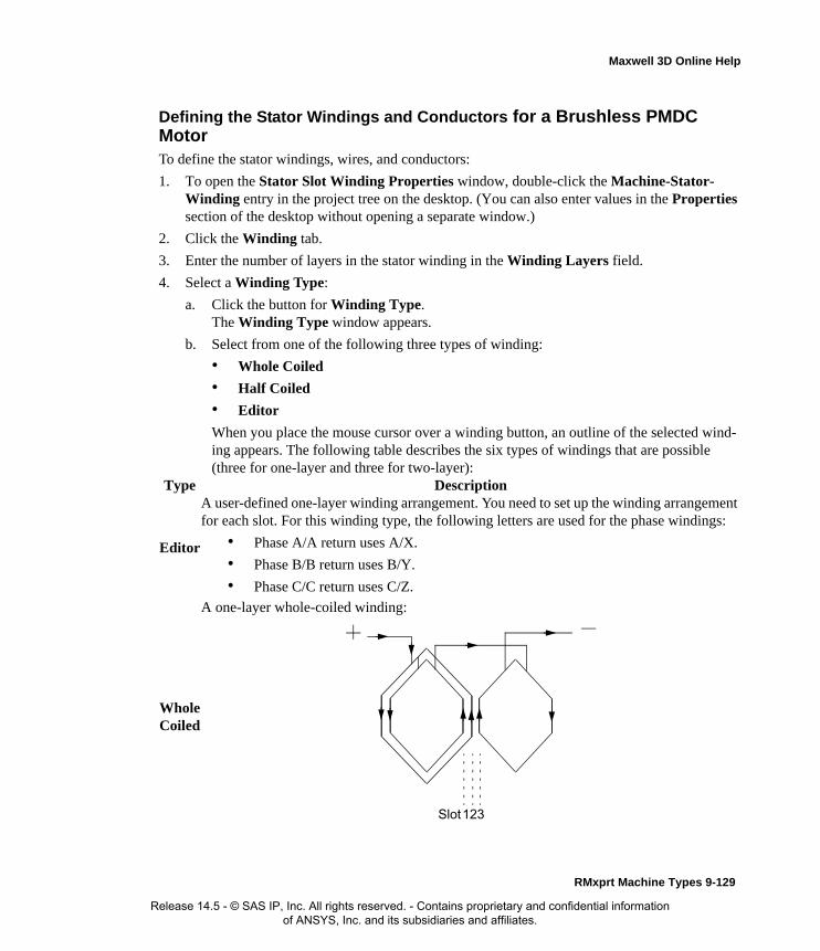
Maxwell 3D Online Help
Defining the Stator Windings and Conductors for a Brushless PMDC MotorTo define the stator windings, wires, and conductors:
1. To open the Stator Slot Winding Properties window, double-click the Machine-Stator-Winding entry in the project tree on the desktop. (You can also enter values in the Properties section of the desktop without opening a separate window.)
2. Click the Winding tab.
3. Enter the number of layers in the stator winding in the Winding Layers field.
4. Select a Winding Type:
a. Click the button for Winding Type.The Winding Type window appears.
b. Select from one of the following three types of winding:
• Whole Coiled
• Half Coiled
• Editor
When you place the mouse cursor over a winding button, an outline of the selected wind-ing appears. The following table describes the six types of windings that are possible (three for one-layer and three for two-layer):
Type Description
Editor
A user-defined one-layer winding arrangement. You need to set up the winding arrangement for each slot. For this winding type, the following letters are used for the phase windings:
• Phase A/A return uses A/X.
• Phase B/B return uses B/Y.
• Phase C/C return uses C/Z.
Whole Coiled
A one-layer whole-coiled winding:
123Slot
RMxprt Machine Types 9-129
Release 14.5 - © SAS IP, Inc. All rights reserved. - Contains proprietary and confidential information of ANSYS, Inc. and its subsidiaries and affiliates.
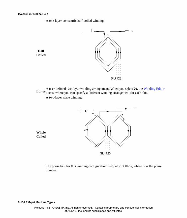
Maxwell 3D Online Help
Half Coiled
A one-layer concentric half-coiled winding:
EditorA user-defined two-layer winding arrangement. When you select 20, the Winding Editor opens, where you can specify a different winding arrangement for each slot.
Whole Coiled
A two-layer wave winding:
The phase belt for this winding configuration is equal to 360/2m, where m is the phase number.
123Slot
123Slot
9-130 RMxprt Machine Types
Release 14.5 - © SAS IP, Inc. All rights reserved. - Contains proprietary and confidential information of ANSYS, Inc. and its subsidiaries and affiliates.

Maxwell 3D Online Help
c. Once you have clicked a button to select a winding, click OK to close the Winding Type window and return to the Properties window.
5. Select a Winding Type.
Half Coiled
A two-layer half-coiled winding:
There is only one coil per phase per pair of poles.
Note For a two layer winding, if you check Constant Pitch in the Winding Editor, only the top layer needs to be defined; the bottom layer will be determined according to the coil pitch.
Note When you place the mouse cursor over a winding, an outline of the selected winding appears.
1 2 3Slot
RMxprt Machine Types 9-131
Release 14.5 - © SAS IP, Inc. All rights reserved. - Contains proprietary and confidential information of ANSYS, Inc. and its subsidiaries and affiliates.
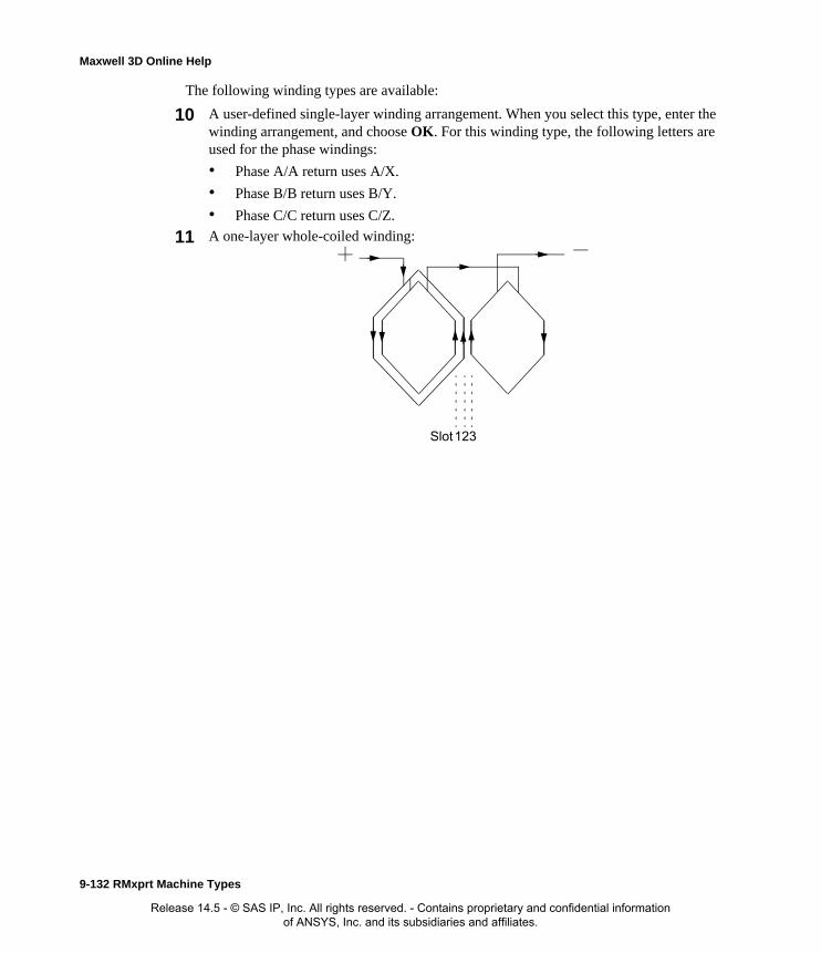
Maxwell 3D Online Help
The following winding types are available:
10 A user-defined single-layer winding arrangement. When you select this type, enter the winding arrangement, and choose OK. For this winding type, the following letters are used for the phase windings:
• Phase A/A return uses A/X.
• Phase B/B return uses B/Y.
• Phase C/C return uses C/Z.
11 A one-layer whole-coiled winding:
123Slot
9-132 RMxprt Machine Types
Release 14.5 - © SAS IP, Inc. All rights reserved. - Contains proprietary and confidential information of ANSYS, Inc. and its subsidiaries and affiliates.

Maxwell 3D Online Help
12 A one-layer concentric half-coiled winding:
20 A user-defined two-layer winding arrangement. When you select this type, enter the winding arrangement, and choose OK.
21 A two-layer wave winding:
The phase belt for this winding configuration is equal to 360/2m, where m is the phase number.
123Slot
123Slot
RMxprt Machine Types 9-133
Release 14.5 - © SAS IP, Inc. All rights reserved. - Contains proprietary and confidential information of ANSYS, Inc. and its subsidiaries and affiliates.
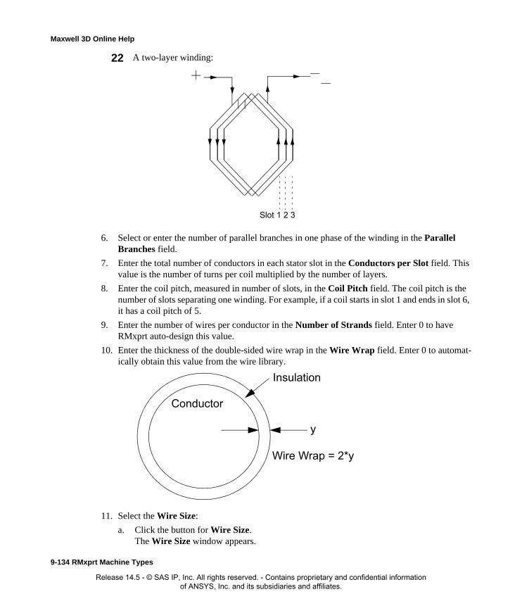
Maxwell 3D Online Help
6. Select or enter the number of parallel branches in one phase of the winding in the Parallel Branches field.
7. Enter the total number of conductors in each stator slot in the Conductors per Slot field. This value is the number of turns per coil multiplied by the number of layers.
8. Enter the coil pitch, measured in number of slots, in the Coil Pitch field. The coil pitch is the number of slots separating one winding. For example, if a coil starts in slot 1 and ends in slot 6, it has a coil pitch of 5.
9. Enter the number of wires per conductor in the Number of Strands field. Enter 0 to have RMxprt auto-design this value.
10. Enter the thickness of the double-sided wire wrap in the Wire Wrap field. Enter 0 to automat-ically obtain this value from the wire library.
11. Select the Wire Size:
a. Click the button for Wire Size.The Wire Size window appears.
22 A two-layer winding:
1 2 3Slot
Insulation
Conductor
y
Wire Wrap = 2*y
9-134 RMxprt Machine Types
Release 14.5 - © SAS IP, Inc. All rights reserved. - Contains proprietary and confidential information of ANSYS, Inc. and its subsidiaries and affiliates.

Maxwell 3D Online Help
b. Select a value from the Wire Diameter pull-down list.
c. Select a wire gauge from the Gauge pull-down menu. You can select from the following options:
The gauge number is based on AWG settings. You can create your own wire table using Machine>Wire, and then you can select this wire table using the Tools>Options>Machine Options command.
d. When you are done setting the wire size, click OK to close the Wire Size window and return to the Properties window.
12. Click the End/Insulation tab.
13. Select or clear the Input Half-turn Length check box.
14. Do one of the following:
• If you selected Input Half-turn Length, then enter the half-turn length of the armature winding in the Half Turn Length field.
• If you cleared Input Half-turn Length, then enter the end length adjustment of the stator coils in the End Adjustment field. The end adjustment is the distance one end of the con-
<number>You can select a specific gauge number. When you select a gauge number, the Wire Diameter field is automatically updated.
USERThis option allows you to manually enter the Wire Diameter. This is useful when you want to enter a diameter that does not correspond to a particular wire gauge.
AUTO
This option sets the Wire Diameter to zero, and RMxprt automatically calculates the optimal value. The diameter information is then written to the output file when you analyze the design.
MIXED
This option allows you to define a conductor that is made of different size wires. For example, a single conductor may consist of 5 wires, 3 wires with a diameter of 0.21mm and 2 with a diameter of 0.13mm.
RMxprt Machine Types 9-135
Release 14.5 - © SAS IP, Inc. All rights reserved. - Contains proprietary and confidential information of ANSYS, Inc. and its subsidiaries and affiliates.

Maxwell 3D Online Help
ductor extends vertically beyond the end of the stator.
15. Enter the inner radius of the base corner in the Base Inner Radius field.
16. Enter the inner diameter of the coil tip in the Tip Inner Diameter field.
17. Enter the distance between two stator coils in the End Clearance field.
18. Enter the thickness of the slot liner insulation in the Slot Liner field.
19. Enter the thickness of the wedge insulation in the Wedge Thickness field.
20. Enter the thickness of the insulation layer in the Layer Insulation field.
21. Enter the limited slot fill factor for the wire design in the Limited Fill Factor field.
22. Click OK to close the Properties window.
EndAdjustment
StatorCoil
End of Stator
SlotInsulation
9-136 RMxprt Machine Types
Release 14.5 - © SAS IP, Inc. All rights reserved. - Contains proprietary and confidential information of ANSYS, Inc. and its subsidiaries and affiliates.

Maxwell 3D Online Help
Winding Editor for a Brushless DC Motor
For a brushless DC motor, you may want to specify a different number of conductors for each stator slot. The Winding Editor makes this possible by enabling you to specify the number of turns for each coil.
To specify the number of turns for each coil:
1. Click Machine>Winding>Edit Layout.The Winding Editor window appears.
2. In the table in the upper left, set which phase you want for each coil and which slot is the “in” and “out” slot for the current in each coil.
3. If you are working on a quarter or half model, you may want to specify a multiplier by clicking the Periodic Multiplier check box and specifying a value.
4. Select or deselect the Constant Turns or Constant Pitch check boxes, depending on whether you want to be able to change these setting in the table above. When these options are selected, you cannot change the turns or pitch.
5. When you are satisfied with the conductor settings, click OK to close the Winding Editor window.
Defining Different Size Wires for a Brushless DC MotorUse the Gauge option in the Wire Size dialog if you have a conductor that is made up different size wires.
To define different size wires:
1. In the Wire Size window, select MIXED from the Gauge pull-down menu.
2. Select either Round or Rectangular as the Wire Type.
3. Enter the appropriate wire data in the table:
• For a round wire:
• Enter the Diameter in the table.
• Enter a Number in the table to specify how many of the conductor’s wires have this diameter.
• For a rectangular wire:
• Enter the Width of the wire in the table.
• Enter the Thickness of the wire in the table.
• Enter the Fillet value in the table.
• Enter a Number in the table to specify how many of the conductor’s wires have this data.
4. Click Add to add the new wire data.
5. Repeat steps 3 and 4 for each size wire you want to add.
6. When you are finished defining the wires, click OK to close the Wire Size window and return
RMxprt Machine Types 9-137
Release 14.5 - © SAS IP, Inc. All rights reserved. - Contains proprietary and confidential information of ANSYS, Inc. and its subsidiaries and affiliates.

Maxwell 3D Online Help
to the RMxprt Properties window.
Stator Winding Data for Brushless PMDC Motors
To access the stator winding data, double-click the Machine-Stator-Winding entry in the project tree.
The Stator Winding Data Properties window contains the following fields:
Note For example, if one conductor is made up of 5 wires, and 3 of those wires have a diameter of 0.21mm, and the other 2 have a diameter of 0.13mm, then the mixed wire size table will have two lines. The first line will list Diameter = 0.21 and Number = 3. The second line will list Diameter = 0.13 and Number = 2. An equivalent wire diameter is displayed as Wire Size value in the Winding tab in the Properties window.
Winding tabWinding Layers The number of winding layers.
Winding Type The type of stator winding. Click the button to open the Winding Type window and choose from Whole Coiled, Half Coiled, and Editor.
Parallel Branches The number of parallel branches in the stator winding.
Conductors per Slot
The number of conductors per stator slot (0 for auto-design).
Coil Pitch The coil pitch measured in number of slots.
Number of Strands
The number of wires per conductor (0 for auto-design).
Wire Wrap The thickness of the double-sided wire wrap (0 to automatically obtain this value from the wire library).
Wire Size The diameter of the wire (0 for auto-design). Click the button to open the Wire Size window where you can specify units, wire type, diameter, and gauge.
End/Insulation tab
Input Half-turn Length
Select or clear this check box to specify whether or not you want to enter the half-turn length. When this check box is selected, the Half Turn Length field appears the next time you open the Properties window. When this check box is selected, the End Adjustment field appears instead.
Half Turn LengthThe half-turn length of the armature winding.
End Adjustment The end length adjustment of the stator coils, which is the distance one end of the conductor extends vertically beyond the end of the stator.
Base Inner Radius
The inner radius of the base corner.
Tip Inner Diameter
The inner diameter of the coil tip.
End Clearance The end clearance between two adjacent coils.
9-138 RMxprt Machine Types
Release 14.5 - © SAS IP, Inc. All rights reserved. - Contains proprietary and confidential information of ANSYS, Inc. and its subsidiaries and affiliates.

Maxwell 3D Online Help
Defining the Rotor Data for a Brushless PMDC MotorThe rotor consists of copper bars in which current is induced by the magnetic fields produced by the stator windings. In the project tree, double-click Machine>Rotor and Machine-Rotor-Pole to define the rotor and the pole.
To define general rotor data:
1. To open the Rotor Data Properties window, double-click the Machine>Rotor entry in the project tree on the desktop. (You can also enter values in the Properties section of the desktop without opening a separate window.)
2. Enter the outer diameter of the rotor in the Outer Diameter field.
3. Enter the inner diameter of the rotor in the Inner Diameter field.
4. Enter the length of the rotor core in the Length field.
5. Select a Steel Type for the rotor core:
a. Click the button for Steel Type.The Select Definition window appears.
b. Select a steel type from the list, or define a new steel type.
c. Click OK to close the Select Definition window and return to the Properties window.
6. Enter the stacking factor for the rotor core in the Stacking Factor field.
7. Select a Pole Type:
Slot Liner The thickness of the slot liner insulation.
Wedge Thickness The thickness of the wedge insulation.
Layer Insulation The thickness of the insulation layer.
Limited Fill Factor
The limited slot fill factor for the wire design.
RMxprt Machine Types 9-139
Release 14.5 - © SAS IP, Inc. All rights reserved. - Contains proprietary and confidential information of ANSYS, Inc. and its subsidiaries and affiliates.

Maxwell 3D Online Help
a. Click the button.The Select Pole Type window appears.
b. Click a button to select the desired pole type (1, 2, 3, 4, or 5). TIP: When you run the mouse over each option, the diagram changes to show that pole type.
c. Click OK to close the Select Pole Type window and return to the Properties window.
8. Click OK to close the Properties window.
Rotor Data for Brushless PMDC Motors
To access the general rotor data, double-click the Machine>Rotor entry in the project tree.
The Rotor Data Properties window contains the following fields:
Defining the Rotor Pole for a Brushless PMDC MotorThe rotor pole drives the electromagnetic field which is coupled with the stator windings. Use the Rotor Pole Data Properties window to define the rotor pole.
To define the rotor pole:
1. To open the Rotor Pole Data Properties window, double-click the Machine-Rotor-Pole entry in the project tree on the desktop. (You can also enter values in the Properties section of the desktop without opening a separate window.)
2. For all pole types except type 4, enter the ratio of the actual arc distance in relation to the max-
Note When you place the mouse cursor over a pole type, an outline of the selected circuit type appears.
Outer Diameter The outer diameter of the rotor core.
Inner Diameter The inner diameter of the rotor core.
Length The length of the rotor core.
Steel Type The steel type of the rotor core. Click the button to open the Select Definition window.
Stacking Factor The stacking factor of the rotor core.
Pole Type The pole type for the rotor. Click this button to open the Select Pole Type window and select from the following types: 1, 2, 3, 4, 5.
Note Some of the fields in the Rotor Pole window change, or are inactive, depending on the Rotor Type you select.
9-140 RMxprt Machine Types
Release 14.5 - © SAS IP, Inc. All rights reserved. - Contains proprietary and confidential information of ANSYS, Inc. and its subsidiaries and affiliates.

Maxwell 3D Online Help
imum possible arc distance in the Embrace field. This value is between 0 and 1.
3. For pole type 4, enter the shaft diameter of the rotor in the Shaft Diameter field.
4. For pole types 1, 2, and 3, enter the distance from the center of the rotor to the polar arc center in the Offset field. Enter 0 for a uniform air gap.
5. For pole type 5, enter the thickness of the bridge across the two poles in the Bridge field.
6. For pole type 5, enter the width of the rib supporting the bridge in the Rib field.
7. Select the type of magnet to use in the rotor pole from the Magnet Type pull-down menu.
8. For pole types 4 and 5, enter the width of the magnet in the Magnet Width field.
9. Enter the maximum radial thickness of the magnet in the Magnet Thickness field.
10. Click OK to close the Properties window.
Pole Embrace = 1.0Pole Embrace = 0.7
MagnetRadius
Offset
Rotor ODRadius
RMxprt Machine Types 9-141
Release 14.5 - © SAS IP, Inc. All rights reserved. - Contains proprietary and confidential information of ANSYS, Inc. and its subsidiaries and affiliates.

Maxwell 3D Online Help
Rotor Pole Data for Brushless PMDC Motors
To access the pole rotor data, double-click the Machine-Rotor-Pole entry in the project tree.
The Rotor Pole Data Properties window may contain the following fields, depending on the pole type specified.
Defining the Shaft Data for a Brushless PMDC MotorTo define the shaft:
1. To open the Shaft Data Properties window, double-click the Machine>Shaft entry in the project tree on the desktop. (You can also enter values in the Properties section of the desktop without opening a separate window.)
2. Select or clear the Magnetic Shaft check box to specify whether or not the shaft is to be made of magnetic material.
3. Click OK to close the Properties window.
Shaft Data for Brushless PMDC Motors
To access the shaft data, double-click the Machine>Shaft entry in the project tree.
The Shaft Data Properties window contains the following fields:
Setting Up Analysis Parameters for a Brushless PMDC MotorTo define the solution data:
1. To open the Solution Setup window, right-click Analysis in the project tree, and click Add Solution Setup.
2. Click the General tab. The Operation Type is Motor for this machine type.
Embrace The pole embrace. For pole types 1, 2, 3, and 5.
Shaft Diameter The shaft diameter of the rotor. For pole type 4.
Offset The pole-arc center offset from the rotor center (0 for a uniform air gap). For pole types 1, 2, and 3.
Bridge The thickness of the bridge across two adjacent poles. For pole type 5.
Rib The width of the rib at the center of two adjacent poles that support the bridge. For pole type 5.
Magnet Type The type of magnet. Click the button to open the Select Definition window. For all pole types.
Magnet Width The maximum width of the magnet. For pole types 4 and 5.
Magnet Thickness The maximum thickness of the magnet. For all pole types.
Magnetic Shaft Select or clear this check box to indicate whether or not the shaft is made of magnetic material.
9-142 RMxprt Machine Types
Release 14.5 - © SAS IP, Inc. All rights reserved. - Contains proprietary and confidential information of ANSYS, Inc. and its subsidiaries and affiliates.

Maxwell 3D Online Help
3. Select the Load Type used in the motor from the following options:
1. Enter the output power developed at the shaft of the motor in the Rated Output Power field.
2. Enter the RMS line-to-line voltage in the Rated Voltage field.
3. Enter the desired output speed of the motor at the load point in the Rated Speed field.
4. Enter the temperature at which the system functions in the Operating Temperature field.
5. Click OK to close the Solution Setup window.
Related Topics:
Solution Data for Brushless PMDC Motors
Analysis Offered
Analysis Offered• Adapted to both Synchronous Motor and Generator
The structures of the salient-pole synchronous motor and the generator are basically the same, but their phasor relationships and the computation methods are slightly different, their output characteristics data are also different. Therefore, RMxprt divides the synchronous machine into two design modules: Synchronous Motor and Synchronous Generator.
• Auto Arrangement of Three-phase Windings
Almost all commonly used three-phase single- and double-layer, half- and whole-type ac windings (including fractional-pitch windings) can be automatically arranged. Users do not need to define coils one by one. RMxprt also supports a double-layer winding with half-turn coils which are auto-arranged in the order of even, odd, even, odd, …, and even, odd, as long as it is physically possible.
When a designer adopts single-layer whole-coiled windings, RMxprt will perform winding arrangement optimization to minimize the average coil pitch. When asymmetric three-phase windings are used, winding arrangement is optimized in such a way that minimum negative-sequence and zero-sequence components are achieved.
• Winding Editor Supporting Any Single- and Double-Layer Windings
Besides taking the great advantage of the winding auto-arrangement function in RMxprt, users can also specify any special winding by using of the Winding Editor function.
Const Speed The speed remains constant in the motor.
Const Power The output power remains constant in the motor.
Const Torque The torque remains constant regardless of the speed. In this case, Tload = Trated, given by the output power divided by the given rated speed.
Linear Torque The torque increases linearly with speed. In this case, Tload = Trated * (n/nrated) where Trated is given by the output power divided by the given rated speed.
Fan Load The load varies nonlinearly with speed. In this case, Tload = Trated * (n/nrated)2 where Trated is given by the output power divided by the given rated speed.
RMxprt Machine Types 9-143
Release 14.5 - © SAS IP, Inc. All rights reserved. - Contains proprietary and confidential information of ANSYS, Inc. and its subsidiaries and affiliates.

Maxwell 3D Online Help
In Winding Editor, through modification of phase belonging, number of turns, in-slot and out-slot number of each coil, it is possible to design single- and double-layer winding arrangement for any purposes.
• Analyze Air-Gap Magnetic Field Distribution
For both uniform and non-uniform air gaps, Schwarz-Christopher Transformation is adopted to solve for the air-gap magnetic field distribution.
• Analyze EMF Waveform and Total Harmonic Distortion (THD)
Based on the analysis of the air-gap magnetic field waveform, taking into account coil short pitch, winding distribution, skew slot, winding connection, load effects and other factors, the emf waveforms in the coils and the windings are analyzed to solve for the emf distortion fac-tors.
• Analyze Dynamic Parameters of Damping Winding
Different from the squirrel-cage winding of the induction machine, the damping winding of the salient-pole synchronous machine is located in the surface of magnetic field poles, which devi-ates greatly along the d- and the q-axes. Furthermore, the connection of damping bars has sev-eral forms. The bars under each pole could be connected, but not connected with those under other poles. All the bars could be connected together. The bars could be connected through end-plate. RMxprt can deal with all those complicated situations and give the dynamic param-eters for the damping winding.
Related Topics:
Setting Up Analysis Parameters for a Brushless PMDC Motor
Solution Data for Brushless PMDC Motors
To access the solution data, right-click Analysis in the project tree, and click Add Solution Setup. For this machine type, there is only one tab, the General tab.
The Solution Setup window contains the following fields:
Related Topics:
Setting Up Analysis Parameters for a Brushless PMDC Motor
Operation Type The operation type is automatically set to Motor for this machine type.
Load Type Select from Const Speed, Const Power, Const Torque, Linear Torque, and Fan Load. The default is Const Power.
Rated Output Power
Type a value for the rated output voltage, and select the units.
Rated Voltage Type a value for the rated voltage, and select the units.
Rated Speed Type a value for the rated speed, and select the units.
Operating Temperature
Type a value for the operating temperature, and select the units.
9-144 RMxprt Machine Types
Release 14.5 - © SAS IP, Inc. All rights reserved. - Contains proprietary and confidential information of ANSYS, Inc. and its subsidiaries and affiliates.

Maxwell 3D Online Help
Switched Reluctance MotorsAfter you have selected Switched Reluctance Motors as your model type, define the following:
• General data, such as the power, voltage, and speed of the motor.
• Circuit data.
• Stator core data, such as the number of poles, diameter, and yoke thickness.
• Stator coil data, such as the slot liner thickness, number of parallel branches, and number of wires in each conductor.
• Rotor core data, such as the air gap dimensions and number of poles in the rotor.
• Shaft data.
• Solution data.
Analysis Approach for Switched Reluctance MotorsThis motor type operates with shaft position feedback to synchronize the commutation of the phase currents with precise rotor position. Typically, both the stator and the rotor are salient to increase the torque-producing characteristics of the motor. The rotor has no windings; the torque is produced by the alignment tendency of the rotor to the stator so that the stator flux linkage is maximized.
In these motors, the stator and rotor have different numbers of poles. The stator phase windings are energized at precise moments synchronized with the position of the rotor. The task of energizing the stator windings is performed by a complex electronic system.
The number of phases in the winding is the ratio of the stator number of poles to the smallest com-mon divider of the stator and the rotor number of poles.
In switched reluctance motors (SRM), the stator and the rotor have a different number of poles, and the stator currents are commutated exactly according to rotor position. The signal of the rotor posi-tion is obtained from a position sensor. The stator windings are triggered one by one, and normally the current in a winding has finished or almost finished freewheeling when the next winding is trig-gered. Therefore, the mutual effects between two phases can be neglected. The voltage equation of one phase is:
where uT is the transistor or diode voltage drop, and Rs is the stator winding resistance. ( , i) is the flux linkage of the winding at rotor position and winding current i, as is shown in Figure 8,
u uT RS i⋅ dΨ θ i,( )dt
---------------------+ +=
Ψ θθ
RMxprt Machine Types 9-145
Release 14.5 - © SAS IP, Inc. All rights reserved. - Contains proprietary and confidential information of ANSYS, Inc. and its subsidiaries and affiliates.

Maxwell 3D Online Help
where the rotor position when the center of the rotor slot is aligned to the winding axis is defined as 0.
Let
and
Then
Figure 8
L ˜Ψ θ i,( )∂
i∂--------------------=
G Ψ i⁄( )∂θ∂
------------------L ˜∂
θ∂---------= =
u uT RS i⋅ L ˜ pi Gωei+ + +=
9-146 RMxprt Machine Types
Release 14.5 - © SAS IP, Inc. All rights reserved. - Contains proprietary and confidential information of ANSYS, Inc. and its subsidiaries and affiliates.

Maxwell 3D Online Help
where e is the rotor speed in electrical rad/s, and p is the differential operator as given by:
The instant electromagnetic torque t2 is:
The input electric power is computed from voltage and current as:
The output mechanical power is:
where Pfw, PCua, Pt, and PFe are frictional and wind loss, armature copper loss, transistor/diode loss, and iron-core loss, respectively.
The average output mechanical shaft torque T2 is:
where is the rotor angular speed in mechanical rad/s.
The efficiency of the electric machine is computed by:
Defining a Switched Reluctance MotorThe general procedure for defining a switched reluctance motor is as follows:
1. Insert a Switched Reluctance motor into a new or existing project.
2. Double-click the Machine entry in the project tree to define the general data.
3. Double-click the Machine-Circuit entry in the project tree to define the control circuit.
4. Double-click the Machine-Stator entry in the project tree to define the stator geometry.
5. Double-click the Machine-Stator-Winding entry in the project tree to define the stator wind-
ω
ptd
d=
t212---Gi
2=
P11T--- u i td⋅ ⋅( )
0
T
=
P2 P1 Pfw PCua Pt PFe+ + +( )–=
T2
P2ω------=
ω
ηP2P1------ 100×= %
RMxprt Machine Types 9-147
Release 14.5 - © SAS IP, Inc. All rights reserved. - Contains proprietary and confidential information of ANSYS, Inc. and its subsidiaries and affiliates.

Maxwell 3D Online Help
ings and conductors.
6. Double-click the Machine-Rotor entry in the project tree to define the rotor geometry.
7. Double-click the Machine-Shaft entry in the project tree to define the magnetism of the shaft.
8. Right-click Analysis in the project tree, and click Add Solution Setup to define the solution data.
9. Choose File>Save to save the project.
10. Choose RMxprt>Analyze to analyze the design.
Once analyzed, the model can be viewed in the Maxwell 2D Modeler, or it can be used to create a new Maxwell 2D project, and a new Maxwell 3D project.
Please refer to the Switched Reluctance Motor Problem application note, on the technical support page of the ANSYS web site, for a specific example.
Defining the General Data for a Switched Reluctance Motor
Use the General window to define the power settings, speed, and period of the motor.
To define the general data:
1. To open the General Data Properties window, double-click the Machine entry in the project tree on the desktop. (You can also enter values in the Properties section of the desktop without opening a separate window.)
2. Enter the energy loss due to friction at the given speed in the Frictional Loss field.
3. Enter the wind loss due to air resistance measured at the reference speed in the Wind Loss field.
4. Enter the given speed in the Reference Speed field.
5. Select DC or CCC from the Control Type pull-down list.
6. Select a Circuit Type from the following types:
The circuit types are based on industry standards. By default, type Full-Voltage, is selected as the circuit type.
7. Click OK to close the Properties window.
Note When you place the cursor over an entry field in the data windows, a brief description of that field appears in the status bar at the bottom of the RMxprt window.
• Full-Voltage
• Half-Voltage
• Coupled-Coil
Note When you place the mouse cursor over a circuit type, an outline schematic of the circuit appears.
9-148 RMxprt Machine Types
Release 14.5 - © SAS IP, Inc. All rights reserved. - Contains proprietary and confidential information of ANSYS, Inc. and its subsidiaries and affiliates.
Maxwell 3D Online Help
General Data for Switched Reluctance Motors
To access the general data, double-click the Machine entry in the project tree.
The General Data Properties window for a three-phase induction motor contains the following fields:
Defining the Circuit Data for a Switched Reluctance MotorUse the Circuit Data Properties window to specify the rated output power, voltage values, circuit type, and speed of the brushless DC motor.
To define the general data:
1. To open the Circuit Data Properties window, double-click the Machine-Circuit entry in the project tree on the desktop. (You can also enter values in the Properties section of the desktop without opening a separate window.)
2. Enter the trigger’s lead angle in electrical degrees in the Lead Angle of Trigger field. The trigger angle is the point at which the magnetic poles interact to begin the motion of the motor. An angle of 0 means that each phase is triggered when its axis is aligned with the rotor slot center. The trigger’s lead angle is shown in the following plot of the open circuit induced volt-age versus position. An angle of 0 means that the induced voltage in the triggered phase is at a
Machine Type The machine type you selected when inserting a new RMxprt design (Switched Reluctance Motor).
Frictional Loss The frictional energy loss (due to friction) measured at the reference speed.
Wind Loss The wind loss (due to air resistance) measured at the reference speed.
Reference Speed The given speed of reference.
Control Type The way the circuit is controlled. Select from DC or CCC (chopped current control, which forces the current to fall between the minimum and maximum values specified).
Circuit Type The drive circuit type. Click the button to open the Circuit Type window and select from the following three types:
• Full-Voltage
• Half-Voltage
• Coupled-Coil
RMxprt Machine Types 9-149
Release 14.5 - © SAS IP, Inc. All rights reserved. - Contains proprietary and confidential information of ANSYS, Inc. and its subsidiaries and affiliates.
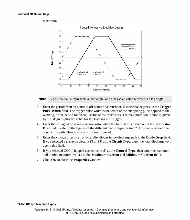
Maxwell 3D Online Help
maximum:
3. Enter the period from on-status to off-status of a transistor, in electrical degrees, in the Trigger Pulse Width field. The trigger pulse width is the width of the energizing pulse applied to the winding, or the period for an ‘on’ status of the transistors. The maximum ‘on’ period is given by 180 degrees plus the value for the lead angle of trigger.
4. Enter the voltage drop across one transistor when the transistor is turned on in the Transistor Drop field. Refer to the figures of the different circuit types in step 2. This value is over one conduction path when the transistors are triggered.
5. Enter the voltage drop on all anti-parallel diodes in the discharge path in the Diode Drop field. If you selected a star-type circuit (S3 or S4) as the Circuit Type, enter the total discharge volt-age in this field.
6. If you selected CCC (chopped current control) as the Control Type, then enter the maximum and minimum current values in the Maximum Current and Minimum Current fields.
7. Click OK to close the Properties window.
Note A positive value represents a lead angle, and a negative value represents a lag angle.
9-150 RMxprt Machine Types
Release 14.5 - © SAS IP, Inc. All rights reserved. - Contains proprietary and confidential information of ANSYS, Inc. and its subsidiaries and affiliates.

Maxwell 3D Online Help
Circuit Data for Switched Reluctance Motors
To access the Circuit Data Properties window, double-click the Machine>Circuit entry in the project tree. When AC is selected at the Control Type, now circuit data properties exist.
Defining the Stator Data for a Switched Reluctance MotorThe stator is the outer lamination stack where the polyphase voltage windings reside.
To define the general stator data:
1. To open the Stator Data Properties window, double-click the Machine>Stator entry in the project tree on the desktop. (You can also enter values in the Properties section of the desktop without opening a separate window.)
2. Enter the Outer Diameter of the stator.
3. Enter the Inner Diameter of the stator.
4. Enter the total length of the stator core in the Length field.
5. Enter the effective magnetic length of the core in the Stacking Factor field. This value typi-cally ranges from between 0.93 and 1.0, and is defined as the total length minus the total lami-nation insulation, divided by the total length.
6. Select a Steel Type for the stator core:
a. Click the button for Steel Type.The Select Definition window appears.
b. Select a steel type from the list, or define a new steel type.
c. Click OK to close the Select Definition window and return to the Properties window.
7. Enter the number of poles the stator core contains in the Number of Poles field.
8. Enter the pole embrace in the Embrace field. The pole embrace is the ratio of the actual pole arc angle to the maximum possible pole angle in the field. This value ranges from between 0 and 1.
9. Enter the thickness of the stator coil yoke in the Yoke Thickness field.
10. Click OK to close the Properties window.
Lead Angle of Trigger
The trigger’s lead angle, in electrical degrees.
Trigger Pulse Width
The period from on-status to off-status for a transistor, in electrical degrees.
Transistor Drop The voltage drop across one transistor when the transistor is turned on.
Diode Drop The voltage drop across one diode in the discharge loop.
Maximum Current
The maximum current for the chopped current control. This field is not available for a DC circuit.
Minimum Current
The minimum current for the chopped current control. This field is not available for a DC circuit.
RMxprt Machine Types 9-151
Release 14.5 - © SAS IP, Inc. All rights reserved. - Contains proprietary and confidential information of ANSYS, Inc. and its subsidiaries and affiliates.

Maxwell 3D Online Help
Stator Data for Switched Reluctance Motors
To access the general stator data, double-click the Machine>Stator entry in the project tree.
The Stator Data Properties window contains the following fields:
Defining the Stator Winding Data for a Switched Reluctance MotorThe stator coils provide the excitation for the rotating magnetic poles.
Use the Stator Coil window to define the parallel branches, wire specifications, and slot liner for the stator coil.
To define the stator coils:
1. To open the Stator Slot Winding Properties window, double-click the Machine-Stator-Winding entry in the project tree on the desktop. (You can also enter values in the Properties section of the desktop without opening a separate window.)
2. Enter the thickness of the insulation between the stator core and the field winding in the Insu-lation Thickness field.
3. Enter the end length adjustment of the stator coils in the End Adjustment field. The end adjustment is the distance one end of the conductor extends vertically beyond the end of the
Outer Diameter The outer diameter of the stator core.
Inner Diameter The inner diameter of the stator core.
Length The length of the stator core.
Stacking Factor The stacking factor of the stator core.
Steel Type The steel type of the stator core. Click the button to open the Select Definition window.
Number of Poles The number of poles the stator core contains.
Embrace The stator pole embrace.
Yoke Thickness The thickness of the yoke at the stator core.
9-152 RMxprt Machine Types
Release 14.5 - © SAS IP, Inc. All rights reserved. - Contains proprietary and confidential information of ANSYS, Inc. and its subsidiaries and affiliates.

Maxwell 3D Online Help
stator.
4. Select or enter the number of parallel branches in one phase of the winding in the Parallel Branches field.
5. Enter the number of turns per stator pole in the Turns per Pole field.
6. Enter the number of wires per conductor in the Number of Strands field. Enter 0 to have RMxprt auto-design this value.
7. Enter the thickness of the double-sided wire wrap in the Wire Wrap field. Enter 0 to automat-ically obtain this value from the wire library.
8. Select the Wire Size:
a. Click the button for Wire Size.The Wire Size window appears.
b. Select a value from the Wire Diameter pull-down list.
c. Select a wire gauge from the Gauge pull-down menu. You can select from the following
EndAdjustment
StatorCoil
End of Stator
Insulation
Conductor
y
Wire Wrap = 2*y
RMxprt Machine Types 9-153
Release 14.5 - © SAS IP, Inc. All rights reserved. - Contains proprietary and confidential information of ANSYS, Inc. and its subsidiaries and affiliates.

Maxwell 3D Online Help
options:
The gauge number is based on AWG settings. You can create your own wire table using Machine>Wire, and then you can select this wire table using the Tools>Options>Machine Options command.
d. When you are done setting the wire size, click OK to close the Wire Size window and return to the Properties window.
9. Enter the conductor area ratio of the coupled circuit to the main circuit in the Coupled Ratio field.
10. Click OK to close the Properties window.
Defining Different Size Wires for a Switched Reluctance MotorUse the Gauge option in the Wire Size window if you have a conductor that is made up different size wires.
To define different size wires:
1. In the Wire Size window, select MIXED from the Gauge pull-down menu.
2. Select either Round or Rectangular as the Wire Type.
3. Enter the appropriate wire data in the table:
• For a round wire:
• Enter the Diameter in the table.
• Enter a Number in the table to specify how many of the conductor’s wires have this diameter.
• For a rectangular wire:
• Enter the Width of the wire in the table.
• Enter the Thickness of the wire in the table.
• Enter the Fillet value in the table.
• Enter a Number in the table to specify how many of the conductor’s wires have this data.
4. Click Add to add the new wire data.
<number>You can select a specific gauge number. When you select a gauge number, the Wire Diameter field is automatically updated.
USERThis option allows you to manually enter the Wire Diameter. This is useful when you want to enter a diameter that does not correspond to a particular wire gauge.
AUTO
This option sets the Wire Diameter to zero, and RMxprt automatically calculates the optimal value. The diameter information is then written to the output file when you analyze the design.
MIXED
This option allows you to define a conductor that is made of different size wires. For example, a single conductor may consist of 5 wires, 3 wires with a diameter of 0.21mm and 2 with a diameter of 0.13mm.
9-154 RMxprt Machine Types
Release 14.5 - © SAS IP, Inc. All rights reserved. - Contains proprietary and confidential information of ANSYS, Inc. and its subsidiaries and affiliates.

Maxwell 3D Online Help
5. Repeat steps 3 and 4 for each size wire you want to add.
6. When you are finished defining the wires, click OK to close the Wire Size window and return to the RMxprt Properties window.
Stator Winding Data for Switched Reluctance Motors
To access the stator winding data, double-click the Machine-Stator-Winding entry in the project tree.
The Stator Winding Data Properties window contains the following fields:
Defining the Rotor Data for a Switched Reluctance MotorThe rotor core channels the flux generated by stator windings and provides shaft torque. The rotor consists of copper bars in which current is induced by the magnetic fields produced by the stator windings. Use the Rotor Data Properties window to define the air gaps, rotor dimensions, and type of steel used in the rotor core. In the project tree, double-click Machine>Rotor to define the rotor.
To define general rotor data:
1. To open the Rotor Data Properties window, double-click the Machine>Rotor entry in the project tree on the desktop. (You can also enter values in the Properties section of the desktop
Note For example, if one conductor is made up of 5 wires, and 3 of those wires have a diameter of 0.21mm, and the other 2 have a diameter of 0.13mm, then the mixed wire size table will have two lines. The first line will list Diameter = 0.21 and Number = 3. The second line will list Diameter = 0.13 and Number = 2. An equivalent wire diameter is displayed as Wire Size value in the Winding tab in the Properties window.
Insulation Thickness
The thickness of the insulation between the stator core and the field winding.
End Adjustment The end length adjustment of the stator coils, which is the distance one end of the conductor extends vertically beyond the end of the stator.
Parallel Branches The number of parallel branches in the stator winding.
Turns per Pole The number of turns per stator pole (0 for auto-design).
Number of Strands
The number of wires per conductor (0 for auto-design).
Wire Wrap The thickness of the double-sided wire wrap (0 to automatically obtain this value from the wire library).
Wire Size The diameter of the wire (0 for auto-design). Click the button to open the Wire Size window where you can specify units, wire type, diameter, and gauge.
Coupled Ratio The conductor area ratio of the coupled circuit to the main circuit.
RMxprt Machine Types 9-155
Release 14.5 - © SAS IP, Inc. All rights reserved. - Contains proprietary and confidential information of ANSYS, Inc. and its subsidiaries and affiliates.

Maxwell 3D Online Help
without opening a separate window.)
2. Enter the outer diameter of the rotor in the Outer Diameter field.
3. Enter the inner diameter of the rotor in the Inner Diameter field.
4. Enter the length of the rotor core in the Length field.
5. Select a Steel Type for the rotor core:
a. Click the button for Steel Type.The Select Definition window appears.
b. Select a steel type from the list, or define a new steel type.
c. Click OK to close the Select Definition window and return to the Properties window.
6. Enter the effective magnetic length of the core in the Stacking Factor field. This value ranges from 0 to 1, and is defined as the total length minus the total lamination insulation, divided by the total length.
7. Enter the number of poles the rotor core contains in the Number of Poles field.
8. Enter the ratio of the actual pole angle in relation to the maximum possible pole angle in the Embrace field. The value ranges from 0 to 1.
9. Enter the thickness of the rotor yoke in the Yoke Thickness field.
10. Click OK to close the Properties window.
Rotor Data for Switched Reluctance Motors
To access the general rotor data, double-click the Machine-Rotor entry in the project tree.
The Rotor Data Properties window contains the following fields:
Defining the Shaft Data for a Switched Reluctance MotorTo define the shaft:
1. To open the Shaft Data Properties window, double-click the Machine>Shaft entry in the project tree on the desktop. (You can also enter values in the Properties section of the desktop without opening a separate window.)
2. Select or clear the Magnetic Shaft check box to specify whether or not the shaft is to be made
Outer Diameter The outer diameter of the rotor core.
Inner Diameter The inner diameter of the rotor core.
Length The length of the rotor core.
Steel Type The steel type of the rotor core. Click the button to open the Select Definition window.
Stacking Factor The stacking factor of the rotor core.
Number of Poles The number of poles the rotor core contains.
Embrace The rotor pole embrace.
Yoke Thickness The thickness of the rotor core yoke.
9-156 RMxprt Machine Types
Release 14.5 - © SAS IP, Inc. All rights reserved. - Contains proprietary and confidential information of ANSYS, Inc. and its subsidiaries and affiliates.
Maxwell 3D Online Help
of magnetic material.
3. Click OK to close the Properties window.
Shaft Data for Switched Reluctance Motors
To access the shaft data, double-click the Machine-Shaft entry in the project tree.
The Shaft Data Properties window contains the following fields:
Setting Up Analysis Parameters for a Switched Reluctance MotorTo define the solution data:
1. To open the Solution Setup window, right-click Analysis in the project tree, and click Add Solution Setup.
2. Click the General tab. The Operation Type is automatically set to Motor for this machine type.
3. Select the Load Type used in the motor from the following options:
1. Enter the output power developed at the shaft of the motor in the Rated Output Power field.
2. Enter the RMS line-to-line voltage in the Rated Voltage field.
3. Enter the desired output speed of the motor at the load point in the Rated Speed field.
4. Enter the temperature at which the system functions in the Operating Temperature field.
5. Click OK to close the Solution Setup window.
Related Topics:
Solution Data for Switched Reluctance Motors
Solution Data for Switched Reluctance Motors
To access the solution data, right-click Analysis in the project tree, and click Add Solution Setup. For this machine type, there is only one tab, the General tab.
Magnetic Shaft Select or clear this check box to indicate whether or not the shaft is made of magnetic material.
Const Speed The speed remains constant in the motor.
Const Power The output power remains constant in the motor.
Const Torque The torque remains constant regardless of the speed. In this case, Tload = Trated, given by the output power divided by the given rated speed.
Linear Torque The torque increases linearly with speed. In this case, Tload = Trated * (n/nrated) where Trated is given by the output power divided by the given rated speed.
Fan Load The load varies nonlinearly with speed. In this case, Tload = Trated * (n/nrated)2 where Trated is given by the output power divided by the given rated speed.
RMxprt Machine Types 9-157
Release 14.5 - © SAS IP, Inc. All rights reserved. - Contains proprietary and confidential information of ANSYS, Inc. and its subsidiaries and affiliates.

Maxwell 3D Online Help
The Solution Setup window contains the following fields:
Related Topics:
Setting Up Analysis Parameters for a Switched Reluctance Motor
Operation Type The operation type is automatically set to Motor for this machine type.
Load Type Select from Const Speed, Const Power, Const Torque, Linear Torque, and Fan Load. The default is Const Power.
Rated Output Power
Type a value for the rated output voltage, and select the units.
Rated Voltage Type a value for the rated voltage, and select the units.
Rated Speed Type a value for the rated speed, and select the units.
Operating Temperature
Type a value for the operating temperature, and select the units.
9-158 RMxprt Machine Types
Release 14.5 - © SAS IP, Inc. All rights reserved. - Contains proprietary and confidential information of ANSYS, Inc. and its subsidiaries and affiliates.

Maxwell 3D Online Help
Line-Start Permanent-Magnet Synchronous MotorsOnce you have selected Line-Start Permanent-Magnet Synchronous Motors as your motor type, you can define the following:
• General data, such as the frequency, winding connection, number of poles, and voltage.
• Stator data, such as the slot type and dimensions, stator diameter, and winding data.
• Rotor pole data, such as its associated dimensions, stacking factor, and magnet type.
• Shaft data.
• Solution data.
By option, you can:
• add a vent to or remove an existing vent from a stator,
• add a damper to or remove a damper from a rotor.
Analysis Approach for Line-Start PM Synchronous MotorsSynchronous motors use a three-phase sinusoidal voltage source to induce a rotating magnetic field in the stator. Applying this three-phase sinusoidal voltage source to the stator winding of a synchro-nous motor yields the rotational magnetic field in the air gap. The permanent magnet poles mounted on the rotor try to align in this rotating field, producing a synchronous torque on the rotor. Upon starting, the damping winding on the rotor generates the asynchronous starting torque, creat-ing a self-starting feature.
The phasor diagram for the line-start permanent-magnet synchronous motor (LSSM) in the fre-quency domain is shown in Figure 6.
Figure 6
RMxprt Machine Types 9-159
Release 14.5 - © SAS IP, Inc. All rights reserved. - Contains proprietary and confidential information of ANSYS, Inc. and its subsidiaries and affiliates.

Maxwell 3D Online Help
In Figure 6, R1, Xd, and Xq are armature resistance, d-axis synchronous reactance, and q-axis syn-chronous reactance, respectively. Xd is the sum of leakage reactance, X1 and d-axis armature reac-tance Xad, and Xq is the sum of X1 and q-axis armature reactance Xaq:
For a given torque angle , the angle that E0 lags U, we have the following:
Solving for Id and Iq yields:
The angle that I legs E0 is:
The power factor angle (or torque angle) that I legs U, is:
Xd X1 Xad+=
Xq X1 Xaq+=
θ
IdXd IqR1+ U θcos E0–=
IdR1– IqXq+ U θsin=
Id
Xq U θcos E0–( ) R1U θsin–
R2
1 XdXq+----------------------------------------------------------------------=
Iq
R1 U θcos E0–( ) XdU θsin–
R2
1 XdXq+----------------------------------------------------------------------=
ΨIdIq-----tanh=
ϕ Ψ θ+=
9-160 RMxprt Machine Types
Release 14.5 - © SAS IP, Inc. All rights reserved. - Contains proprietary and confidential information of ANSYS, Inc. and its subsidiaries and affiliates.

Maxwell 3D Online Help
The input power (electric power) can now be computed from voltage and current as:
The output power (mechanical power) is:
where Pfw, PCu, and PFe are frictional and wind loss, armature copper loss, and iron-core loss, respectively.
The output mechanical power (torque) T2 is:
where is the synchronous speed in rad/s.
The efficiency is computed by:
The motor is started the same way as for an induction motor, by using a squirrel-cage-type winding -- called a damper winding in this case -- that is mounted on the rotor, producing the starting torque.
Defining a Line-Start Permanent Magnet Synchronous MotorThe general procedure for defining a line-start synchronous motor is as follows:
1. Insert a line-start synchronous motor into a new or existing project.
2. Double-click the Machine entry in the project tree to define the general data.
3. Double-click the Machine-Stator entry in the project tree to define the stator geometry.
4. Double-click the Machine-Stator-Slot entry in the project tree to define the stator slot dimen-sions.
5. Double-click the Machine-Stator-Winding entry in the project tree to define the stator wind-ings and conductors.
6. Double-click the Machine-Rotor entry in the project tree to define the rotor geometry.
7. Double-click the Machine-Rotor-Pole entry in the project tree to define the pole, embrace, offset, and air gap data for the rotor pole.
8. Double-click the Machine-Shaft entry in the project tree to define the magnetism of the shaft.
9. Right-click Analysis in the project tree, and click Add Solution Setup to define the solution
P1 3UI ϕcos=
P2 P1 Pfw PCu PFe+ +( )–=
T2
P2ω------=
ω
ηP2P1------ 100×= %
RMxprt Machine Types 9-161
Release 14.5 - © SAS IP, Inc. All rights reserved. - Contains proprietary and confidential information of ANSYS, Inc. and its subsidiaries and affiliates.
Maxwell 3D Online Help
data.
10. Choose File>Save to save the project.
11. Choose RMxprt>Analyze to analyze the design.
Once analyzed, the model can be viewed in the Maxwell 2D Modeler, or it can be used to create a new Maxwell 2D project, and a new Maxwell 3D design.
Defining the General Data for a Line-Start PM Synchronous Motor
Use the General window to define the basic parameters of the motor, such as the motor’s rated out-put power, rated voltage, losses, and connection type.
To define the general data:
1. To open the General Data Properties window, double-click the Machine entry in the project tree on the desktop. (You can also enter values in the Properties section of the desktop without opening a separate window.)
2. Enter the number of poles for the machine in the Number of Poles field. This value is the total number of poles in the stator (or the number of pole pairs multiplied by two).
3. Enter the energy loss due to friction at the given speed in the Frictional Loss field.
4. Enter the wind loss due to air resistance measured at the reference speed in the Wind Loss field.
5. Enter the given speed in the Reference Speed field.
6. Click OK to close the Properties window.
General Data for Line-Start PM Synchronous MotorsTo access the general data, double-click the Machine entry in the project tree.
The General Data Properties window for a three-phase induction motor contains the following fields:
Defining the Stator Data for a Line-Start PM Synchronous Motor
The stator is the outer lamination stack where the polyphase voltage windings reside.
Note When you place the cursor over an entry field in the data windows, a brief description of that field appears in the status bar at the bottom of the RMxprt window.
Machine Type The machine type you selected when inserting a new RMxprt design (Line-Start PM Synchronous Motor).
Number of Poles The number of poles the machine contains.
Frictional Loss The frictional energy loss (due to friction) measured at the reference speed.
Wind Loss The wind loss (due to air resistance) measured at the reference speed.
Reference Speed The given speed of reference.
9-162 RMxprt Machine Types
Release 14.5 - © SAS IP, Inc. All rights reserved. - Contains proprietary and confidential information of ANSYS, Inc. and its subsidiaries and affiliates.
Maxwell 3D Online Help
Use the Stator Data, Stator Slot Data, and Stator Winding Data windows to define the stator data, such as physical dimensions of the lamination, windings, and conductors.
To define the general stator data:
1. To open the Stator Data Properties window, double-click the Machine>Stator entry in the project tree on the desktop. (You can also enter values in the Properties section of the desktop without opening a separate window.)
2. Enter the Outer Diameter of the stator.
3. Enter the Inner Diameter of the stator.
4. Enter the length of the stator core in the Length field.
5. Enter the effective magnetic length of the core in the Stacking Factor field.
6. Select a Steel Type for the stator core:
a. Click the button for Steel Type.The Select Definition window appears.
b. Select a steel type from the list, or define a new steel type.
c. Click OK to close the Select Definition window and return to the Properties window.
7. Enter the Number of Slots in the stator.
8. Select the Slot Type:
a. Click the button for the Slot Type.The Select Slot Type window appears.
b. Select a slot type (available types include 1 through 4).
c. Click OK to close the Select Slot Type window and return to the Properties window.
9. Enter the skew width, measured in slot number, in the Skew Width field.
10. Click OK to close the Properties window.
Stator Data for Line-Start PM Synchronous Motors
To access the general stator data, double-click the Machine>Stator entry in the project tree.
The Stator Data Properties window contains the following fields:
Note When you place the mouse cursor over the slot type, a schematic of the selected type appears, displaying the slot dimension variables.
Outer Diameter The outer diameter of the stator core.
Inner Diameter The inner diameter of the stator core.
Length The length of the stator core.
Stacking Factor The stacking factor of the stator core.
Steel Type The steel type of the stator core. Click the button to open the Select Definition window.
RMxprt Machine Types 9-163
Release 14.5 - © SAS IP, Inc. All rights reserved. - Contains proprietary and confidential information of ANSYS, Inc. and its subsidiaries and affiliates.

Maxwell 3D Online Help
Defining the Stator Slots for a Line-Start PM Synchronous MotorTo define the slot type:
1. To open the Stator Slot Data Properties window, double-click the Machine-Stator-Slot entry in the project tree on the desktop. (You can also enter values in the Properties section of the desktop without opening a separate window.)
2. Optionally, to automatically design the dimensions of slots Hs2, Bs1, and Bs2, select the Auto Design check box.
3. Optionally, to design dimensions of slots Bs1 and Bs2 based on the stator tooth width, select the Parallel Tooth check box, and enter a value in the Tooth Width field.
4. Enter the available slot dimensions.
5. Click OK to close the Properties window.
Stator Slot Data for Line-Start PM Synchronous Motors
To access the stator slot data, double-click the Machine-Stator-Slot entry in the project tree.
Number of Slots The number of slots the stator core contains.
Slot Type The type of slots in the stator core. Click the button to open the Select Slot Type window.
Skew Width The skew width measured in slot number.
Hs0 Always available.
Hs2 Available only when Auto Design is cleared. When Auto Design is selected, this slot dimension is determined automatically.
Bs0 Always available.
Bs1 Available only when Auto Design and Parallel Tooth are both cleared. When Auto Design is selected, this slot dimension is determined automatically. When Parallel Tooth is selected, this slot dimension is determined based on the value entered in the Tooth Width field.
Bs2 Available only when Auto Design and Parallel Tooth are both cleared. When Auto Design is selected, this slot dimension is determined automatically. When Parallel Tooth is selected, this slot dimension is determined based on the value entered in the Tooth Width field.
Rs Rs is added when the slot type is 3 or 4.
9-164 RMxprt Machine Types
Release 14.5 - © SAS IP, Inc. All rights reserved. - Contains proprietary and confidential information of ANSYS, Inc. and its subsidiaries and affiliates.
Maxwell 3D Online Help
The Stator Slot Data Properties window contains the following fields:
Defining the Stator Windings and Conductors for a Line-Start PM Synchronous MotorTo define the stator windings and conductors:
1. To open the Stator Slot Winding Properties window, double-click the Machine-Stator-Winding entry in the project tree on the desktop. (You can also enter values in the Properties section of the desktop without opening a separate window.)
2. Click the Winding tab.
3. Enter the number of layers in the stator winding in the Winding Layers field.
4. Select the Winding Type for the stator:
a. Click the button for Winding Type.The Winding Type window appears.
b. Select from one of the following three types of winding:
• Whole Coiled
• Half Coiled
Auto Design Select or clear this to enable or disable auto-design of slots Hs2, Bs1, and Bs2. When this check box is selected, only two other fields appear in the window: Hs0 and Bs0.
Parallel Tooth
Select this to design Bs1 and Bs2 based on the tooth width. When this check box is selected, the Bs1 and Bs2 fields are removed, and the Tooth Width field is added.
Tooth WidthThe tooth width for the parallel tooth, on which Bs1 and Bs2 are designed.
Hs0 A slot dimension (see the diagram shown in the modeling window when Machine-Stator-Slot is selected).
Hs1 A slot dimension (see the diagram shown in the modeling window when Machine-Stator-Slot is selected).
Hs2 A slot dimension (see the diagram shown in the modeling window when Machine-Stator-Slot is selected).
Bs0 A slot dimension (see the diagram shown in the modeling window when Machine-Stator-Slot is selected).
Bs1 A slot dimension (see the diagram shown in the modeling window when Machine-Stator-Slot is selected).
Bs2 A slot dimension (see the diagram shown in the modeling window when Machine-Stator-Slot is selected).
Rs A slot dimension. (see the diagram shown in the modeling window when Machine-Stator-Slot is selected). Rs is added when the slot type is 3 or 4.
RMxprt Machine Types 9-165
Release 14.5 - © SAS IP, Inc. All rights reserved. - Contains proprietary and confidential information of ANSYS, Inc. and its subsidiaries and affiliates.

Maxwell 3D Online Help
• Editor
c. Click OK to close the Winding Type window and return to the Properties window.
5. Select or enter the number of parallel branches in one phase of the winding in the Parallel Branches field.
6. Enter the total number of conductors in each stator slot in the Conductors per Slot field. This value is the number of turns per coil multiplied by the number of layers.
7. Enter the coil pitch, measured in number of slots, in the Coil Pitch field. The coil pitch is the number of slots separating one winding. For example, if a coil starts in slot 1 and ends in slot 6, it has a coil pitch of 5.
8. Enter the number of wires per conductor in the Number of Strands field. Enter 0 to have RMxprt auto-design this value.
9. Enter the thickness of the double-sided wire wrap in the Wire Wrap field. Enter 0 to automat-ically obtain this value from the wire library.
10. Select the Wire Size:
a. Click the button for Wire Size.The Wire Size window appears.
b. Select a value from the Wire Diameter pull-down list.
c. Select a wire gauge from the Gauge pull-down menu. You can select from the following
Note When you place the mouse cursor over the winding type, a schematic of that type appears.
Insulation
Conductor
y
Wire Wrap = 2*y
9-166 RMxprt Machine Types
Release 14.5 - © SAS IP, Inc. All rights reserved. - Contains proprietary and confidential information of ANSYS, Inc. and its subsidiaries and affiliates.
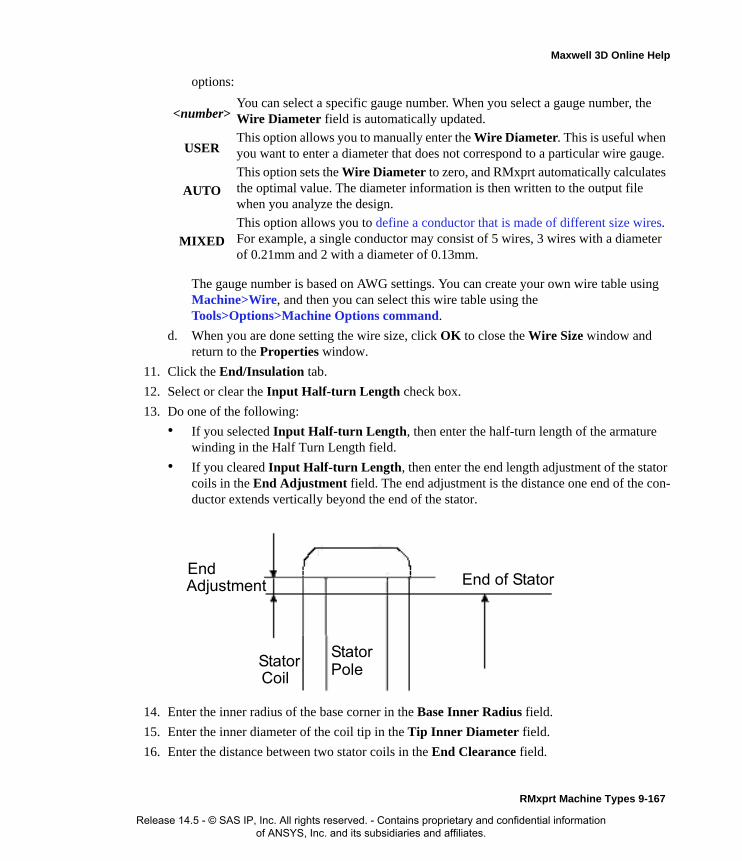
Maxwell 3D Online Help
options:
The gauge number is based on AWG settings. You can create your own wire table using Machine>Wire, and then you can select this wire table using the Tools>Options>Machine Options command.
d. When you are done setting the wire size, click OK to close the Wire Size window and return to the Properties window.
11. Click the End/Insulation tab.
12. Select or clear the Input Half-turn Length check box.
13. Do one of the following:
• If you selected Input Half-turn Length, then enter the half-turn length of the armature winding in the Half Turn Length field.
• If you cleared Input Half-turn Length, then enter the end length adjustment of the stator coils in the End Adjustment field. The end adjustment is the distance one end of the con-ductor extends vertically beyond the end of the stator.
14. Enter the inner radius of the base corner in the Base Inner Radius field.
15. Enter the inner diameter of the coil tip in the Tip Inner Diameter field.
16. Enter the distance between two stator coils in the End Clearance field.
<number>You can select a specific gauge number. When you select a gauge number, the Wire Diameter field is automatically updated.
USERThis option allows you to manually enter the Wire Diameter. This is useful when you want to enter a diameter that does not correspond to a particular wire gauge.
AUTO
This option sets the Wire Diameter to zero, and RMxprt automatically calculates the optimal value. The diameter information is then written to the output file when you analyze the design.
MIXED
This option allows you to define a conductor that is made of different size wires. For example, a single conductor may consist of 5 wires, 3 wires with a diameter of 0.21mm and 2 with a diameter of 0.13mm.
EndAdjustment
StatorCoil
End of Stator
StatorPole
RMxprt Machine Types 9-167
Release 14.5 - © SAS IP, Inc. All rights reserved. - Contains proprietary and confidential information of ANSYS, Inc. and its subsidiaries and affiliates.
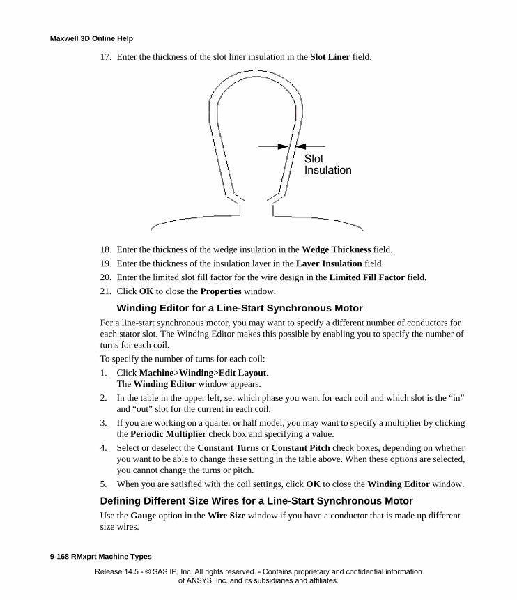
Maxwell 3D Online Help
17. Enter the thickness of the slot liner insulation in the Slot Liner field.
18. Enter the thickness of the wedge insulation in the Wedge Thickness field.
19. Enter the thickness of the insulation layer in the Layer Insulation field.
20. Enter the limited slot fill factor for the wire design in the Limited Fill Factor field.
21. Click OK to close the Properties window.
Winding Editor for a Line-Start Synchronous MotorFor a line-start synchronous motor, you may want to specify a different number of conductors for each stator slot. The Winding Editor makes this possible by enabling you to specify the number of turns for each coil.
To specify the number of turns for each coil:
1. Click Machine>Winding>Edit Layout.The Winding Editor window appears.
2. In the table in the upper left, set which phase you want for each coil and which slot is the “in” and “out” slot for the current in each coil.
3. If you are working on a quarter or half model, you may want to specify a multiplier by clicking the Periodic Multiplier check box and specifying a value.
4. Select or deselect the Constant Turns or Constant Pitch check boxes, depending on whether you want to be able to change these setting in the table above. When these options are selected, you cannot change the turns or pitch.
5. When you are satisfied with the coil settings, click OK to close the Winding Editor window.
Defining Different Size Wires for a Line-Start Synchronous Motor
Use the Gauge option in the Wire Size window if you have a conductor that is made up different size wires.
SlotInsulation
9-168 RMxprt Machine Types
Release 14.5 - © SAS IP, Inc. All rights reserved. - Contains proprietary and confidential information of ANSYS, Inc. and its subsidiaries and affiliates.

Maxwell 3D Online Help
To define different size wires:
1. In the Wire Size window, select MIXED from the Gauge pull-down menu.
2. Select either Round or Rectangular as the Wire Type.
3. Enter the appropriate wire data in the table:
• For a round wire:
• Enter the Diameter in the table.
• Enter a Number in the table to specify how many of the conductor’s wires have this diameter.
• For a rectangular wire:
• Enter the Width of the wire in the table.
• Enter the Thickness of the wire in the table.
• Enter the Fillet value in the table.
• Enter a Number in the table to specify how many of the conductor’s wires have this data.
4. Click Add to add the new wire data.
5. Repeat steps 3 and 4 for each size wire you want to add.
6. When you are finished defining the wires, click OK to close the Wire Size window and return to the RMxprt Properties window.
Stator Winding Data for Line-Start PM Synchronous Motors
To access the stator winding data, double-click the Machine-Stator-Winding entry in the project tree.
The Stator Winding Data Properties window contains the following fields:
Note For example, if one conductor is made up of 5 wires, and 3 of those wires have a diameter of 0.21mm, and the other 2 have a diameter of 0.13mm, then the mixed wire size table will have two lines. The first line will list Diameter = 0.21 and Number = 3. The second line will list Diameter = 0.13 and Number = 2. An equivalent wire diameter is displayed as Wire Size value in the Winding tab in the Properties window.
Winding tabWinding Layers The number of winding layers.
Winding Type The type of stator winding. Click the button to open the Winding Type window and choose from Whole Coiled, Half Coiled, and Editor.
Parallel Branches The number of parallel branches in the stator winding.
Conductors per Slot
The number of conductors per stator slot (0 for auto-design).
Coil Pitch The coil pitch measured in number of slots.
Number of Strands
The number of wires per conductor (0 for auto-design).
RMxprt Machine Types 9-169
Release 14.5 - © SAS IP, Inc. All rights reserved. - Contains proprietary and confidential information of ANSYS, Inc. and its subsidiaries and affiliates.

Maxwell 3D Online Help
Wire Wrap The thickness of the double-sided wire wrap (0 to automatically obtain this value from the wire library).
Wire Size The diameter of the wire (0 for auto-design). Click the button to open the Wire Size window where you can specify units, wire type, diameter, and gauge.
End/Insulation tab
Input Half-turn Length
Select or clear this check box to specify whether or not you want to enter the half-turn length. When this check box is selected, the Half Turn Length field appears the next time you open the Properties window. When this check box is selected, the End Adjustment field appears instead.
Half Turn LengthThe half-turn length of the armature winding.
End Adjustment The end length adjustment of the stator coils, which is the distance one end of the conductor extends vertically beyond the end of the stator.
Base Inner Radius
The inner radius of the base corner.
Tip Inner Diameter
The inner diameter of the coil tip.
End Clearance The end clearance between two adjacent coils.
Slot Liner The thickness of the slot liner insulation.
Wedge Thickness The thickness of the wedge insulation.
Layer Insulation The thickness of the insulation layer.
Limited Fill Factor
The limited slot fill factor for the wire design.
9-170 RMxprt Machine Types
Release 14.5 - © SAS IP, Inc. All rights reserved. - Contains proprietary and confidential information of ANSYS, Inc. and its subsidiaries and affiliates.

Maxwell 3D Online Help
Optional Vent for Line-Start PM Synchronous Motor Stator
To add a Vent to the stator, select the stator icon and right-click to display the pop-up menu with Insert Vent.
The vent is shown in the project tree under the stator.
To remove an existing Vent, select the stator and right-click to display the up-up menu with Remove Vent.
The Vent Data properties window contains the following fields.
Defining the Rotor Data for a Line-Start PM Synchronous Motor
The rotor consists of copper bars in which current is induced by the magnetic fields produced by the stator windings. In the project tree, double-click Machine-Rotor and Machine-Rotor-Pole to define the rotor and the pole.
To define general rotor data:
1. To open the Rotor Data Properties window, double-click the Machine>Rotor entry in the project tree on the desktop. (You can also enter values in the Properties section of the desktop without opening a separate window.)
2. Enter the outer diameter of the rotor in the Outer Diameter field.
3. Enter the inner diameter of the rotor in the Inner Diameter field.
4. Enter the length of the rotor core in the Length field.
5. Select a Steel Type for the rotor core:
a. Click the button for Steel Type.The Select Definition window appears.
b. Select a steel type from the list, or define a new steel type.
c. Click OK to close the Select Definition window and return to the Properties window.
6. Enter the effective magnetic length of the rotor core in the Stacking Factor field. This value ranges from 0 to 1 and is defined as the total length minus the total lamination insulation, divided by the total length. A value of 1 indicates that the rotor is not laminated.
7. Select a Pole Type:
a. Click the button.The Select Pole Type window appears.
b. Click a button to select the desired pole type (1, 2, 3, 4, 5, 6, 7, or 8). TIP: When you run
Vent Ducts Number of radial vent ducts
Duct Width Width of radial vent ducts
Magnetic spacer width
Width of magnetic spacer which hold vent ducts. 0 for non-magnetic spacer.
Duct pitch Vent ducts.
RMxprt Machine Types 9-171
Release 14.5 - © SAS IP, Inc. All rights reserved. - Contains proprietary and confidential information of ANSYS, Inc. and its subsidiaries and affiliates.
Maxwell 3D Online Help
the mouse over each option, the diagram changes to show that pole type.
c. Click OK to close the Select Pole Type window and return to the Properties window.
8. Click OK to close the Properties window.
Rotor Data for Line-Start PM Synchronous Motors
To access the general rotor data, double-click the Machine>Rotor entry in the project tree.
The Rotor Data Properties window contains the following fields:
Defining the Rotor Pole for a Line-Start PM Synchronous MotorThe rotor pole drives the electromagnetic field which is coupled with the stator windings. Use the Rotor Pole Data Properties window to define the rotor pole.
To define the rotor pole:
1. To open the Rotor Pole Data Properties window, double-click the Machine-Rotor-Pole entry in the project tree on the desktop. (You can also enter values in the Properties section of the desktop without opening a separate window.)
2. Enter the limited diameter for the magnet ducts in the D1 field.
3. Enter one or more of the following magnet duct dimensions, depending on the pole type selected: O1, O2, B1.
4. For all pole types except number 8, enter the width of the rib supporting the bridge in the Rib field.
5. Select the type of magnet to use in the rotor pole:
a. Click Magnet Type button.
Note When you place the mouse cursor over a pole type, an outline of the selected circuit type appears.
Outer Diameter The outer diameter of the rotor core.
Inner Diameter The inner diameter of the rotor core.
Length The length of the rotor core.
Steel Type The steel type of the rotor core. Click the button to open the Select Definition window.
Stacking Factor The stacking factor of the rotor core.
Pole Type The pole type for the rotor. Click this button to open the Select Pole Type window and select from the following types: 1, 2, 3, 4, 5, 6, 7, 8. When you mouse over each button, a diagram appears for that pole type, showing the arrangement and dimensions.
Note Some of the fields in the Rotor Pole window change, or are inactive, depending on the Rotor Type you select.
9-172 RMxprt Machine Types
Release 14.5 - © SAS IP, Inc. All rights reserved. - Contains proprietary and confidential information of ANSYS, Inc. and its subsidiaries and affiliates.
Maxwell 3D Online Help
The Select Definition window appears.
b. Select a material.
c. Click OK to close the Select Definition window and return to the Properties window.
6. Enter the total width of all magnets per pole in the Magnet Width field.
7. Enter the maximum radial thickness of the magnet in the Magnet Thickness field.
8. Click OK to close the Properties window.
Rotor Pole Data for Line-Start PM Synchronous Motors
To access the pole rotor data, double-click the Machine-Rotor-Pole entry in the project tree.
The Rotor Pole Data Properties window contains the following fields:
Optional Rotor Damper for Line-Start PM Synchronous MotorTo add a damper, right-click on the rotor item in the project tree to display the pop-up menu with Insert Damper.
To remove an existing damper, right-click on the rotor icon in the project tree to display the short-cut menu with Remove Damper.
D1 The limited diameter for the magnet ducts. See the diagrams in the Select Pole Type window for the location of each dimension and which pole types require which dimensions.
O1 A magnet duct dimension. See the diagrams in the Select Pole Type window for the location of each dimension and which pole types require which dimensions.
O2 A magnet duct dimension. See the diagrams in the Select Pole Type window for the location of each dimension and which pole types require which dimensions.
B1 A magnet duct dimension. See the diagrams in the Select Pole Type window for the location of each dimension and which pole types require which dimensions.
Rib The width of the rib at the center of two adjacent poles that support the bridge. For pole types except number 8.
Magnet Type The type of magnet. Click the button to open the Select Definition window. For all pole types.
Magnet Width The maximum width of the magnet. For all pole types.
Magnet Thickness The maximum thickness of the magnet. For all pole types.
RMxprt Machine Types 9-173
Release 14.5 - © SAS IP, Inc. All rights reserved. - Contains proprietary and confidential information of ANSYS, Inc. and its subsidiaries and affiliates.
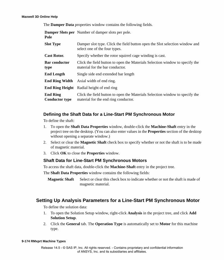
Maxwell 3D Online Help
The Damper Data properties window contains the following fields.
Defining the Shaft Data for a Line-Start PM Synchronous MotorTo define the shaft:
1. To open the Shaft Data Properties window, double-click the Machine-Shaft entry in the project tree on the desktop. (You can also enter values in the Properties section of the desktop without opening a separate window.)
2. Select or clear the Magnetic Shaft check box to specify whether or not the shaft is to be made of magnetic material.
3. Click OK to close the Properties window.
Shaft Data for Line-Start PM Synchronous MotorsTo access the shaft data, double-click the Machine-Shaft entry in the project tree.
The Shaft Data Properties window contains the following fields:
Setting Up Analysis Parameters for a Line-Start PM Synchronous MotorTo define the solution data:
1. To open the Solution Setup window, right-click Analysis in the project tree, and click Add Solution Setup.
2. Click the General tab. The Operation Type is automatically set to Motor for this machine type.
Damper Slots per Pole
Number of damper slots per pole.
Slot Type Damper slot type. Click the field button open the Slot selection window and select one of the four types.
Cast Rotor. Specify whether the rotor squirrel cage winding is cast.
Bar conductor type
Click the field button to open the Materials Selection window to specify the material for the bar conductor.
End Length Single side end extended bar length
End Ring Width Axial width of end ring.
End Ring Height Radial height of end ring
End Ring Conductor type
Click the field button to open the Materials Selection window to specify the material for the end ring conductor.
Magnetic Shaft Select or clear this check box to indicate whether or not the shaft is made of magnetic material.
9-174 RMxprt Machine Types
Release 14.5 - © SAS IP, Inc. All rights reserved. - Contains proprietary and confidential information of ANSYS, Inc. and its subsidiaries and affiliates.

Maxwell 3D Online Help
3. Select the Load Type used in the motor from the following options:
4. Enter the output power developed at the shaft of the motor in the Rated Output Power field.
5. Enter the RMS line-to-line voltage in the Rated Voltage field.
6. Enter the desired output speed of the motor at the load point in the Rated Speed field.
7. Enter the temperature at which the system functions in the Operating Temperature field.
8. Click the Line-Start PM Synchronous Motor tab.
9. Select Wye or Delta from the Winding Connection pull-down list.
10. Click OK to close the Solution Setup window.
Related Topics:
Solution Data for Line-Start PM Synchronous Motors
Solution Data for Line-Start PM Synchronous MotorsTo access the solution data, right-click Analysis in the project tree, and click Add Solution Setup. For this machine type, there is only one tab, the General tab.
The Solution Setup window contains the following fields:
Related Topics:
Const Speed The speed remains constant in the motor.
Const Power The output power remains constant in the motor.
Const Torque The torque remains constant regardless of the speed. In this case, Tload = Trated, given by the output power divided by the given rated speed.
Linear Torque The torque increases linearly with speed. In this case, Tload = Trated * (n/nrated) where Trated is given by the output power divided by the given rated speed.
Fan Load The load varies nonlinearly with speed. In this case, Tload = Trated * (n/nrated)2 where Trated is given by the output power divided by the given rated speed.
Operation Type General tab. The operation type is automatically set to Motor for this machine type.
Load Type General tab. Select from Const Speed, Const Power, Const Torque, Linear Torque, and Fan Load. The default is Const Power.
Rated Output Power
General tab. Type a value for the rated output voltage, and select the units.
Rated Voltage General tab. Type a value for the rated voltage, and select the units.
Rated Speed General tab. Type a value for the rated speed, and select the units.
Operating Temperature
General tab. Type a value for the operating temperature, and select the units.
Winding Connection
Line-Start PM Synchronous Motor tab. Select Wye or Delta from the Winding Connection pull-down list.
RMxprt Machine Types 9-175
Release 14.5 - © SAS IP, Inc. All rights reserved. - Contains proprietary and confidential information of ANSYS, Inc. and its subsidiaries and affiliates.

Maxwell 3D Online Help
Setting Up Analysis Parameters for a Line-Start PM Synchronous Motor
9-176 RMxprt Machine Types
Release 14.5 - © SAS IP, Inc. All rights reserved. - Contains proprietary and confidential information of ANSYS, Inc. and its subsidiaries and affiliates.
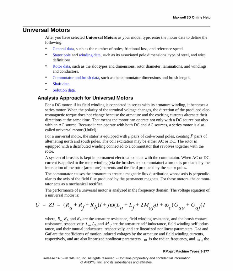
Maxwell 3D Online Help
Universal MotorsAfter you have selected Universal Motors as your model type, enter the motor data to define the following:
• General data, such as the number of poles, frictional loss, and reference speed.
• Stator pole and winding data, such as its associated pole dimensions, type of steel, and wire definitions.
• Rotor data, such as the slot types and dimensions, rotor diameter, laminations, and windings and conductors.
• Commutator and brush data, such as the commutator dimensions and brush length.
• Shaft data.
• Solution data.
Analysis Approach for Universal MotorsFor a DC motor, if its field winding is connected in series with its armature winding, it becomes a series motor. When the polarity of the terminal voltage changes, the direction of the produced elec-tromagnetic torque does not change because the armature and the exciting currents alternate their directions at the same time. That means the motor can operate not only with a DC source but also with an AC source. Because it can operate with both DC and AC sources, a series motor is also called universal motor (UniM).
For a universal motor, the stator is equipped with p pairs of coil-wound poles, creating P pairs of alternating north and south poles. The coil excitation may be either AC or DC. The rotor is equipped with a distributed winding connected to a commutator that revolves together with the rotor.
A system of brushes is kept in permanent electrical contact with the commutator. When AC or DC current is applied to the rotor winding (via the brushes and commutator) a torque is produced by the interaction of the rotor (armature) currents and the field produced by the stator poles.
The commutator causes the armature to create a magnetic flux distribution whose axis is perpendic-ular to the axis of the field flux produced by the permanent magnets. For these motors, the commu-tator acts as a mechanical rectifier.
The performance of a universal motor is analyzed in the frequency domain. The voltage equation of a universal motor is:
where, Ra, Rf, and Rb are the armature resistance, field winding resistance, and the brush contact resistance, respectively. La, Lf, and Maf are the armature self inductance, field winding self induc-tance, and their mutual inductance, respectively, and are linearized nonlinear parameters. Gaa and Gaf are the coefficients of motion induced voltages by the armature and field winding currents, respectively, and are also linearized nonlinear parameters. is the radian frequency, and e the
U ZI Ra Rf Rb+ +( )I jω La Lf 2Maf+ +( )I ωe Gaa Gaf+( )I+ += =
ω ω
RMxprt Machine Types 9-177
Release 14.5 - © SAS IP, Inc. All rights reserved. - Contains proprietary and confidential information of ANSYS, Inc. and its subsidiaries and affiliates.
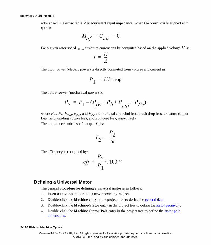
Maxwell 3D Online Help
rotor speed in electric rad/s. Z is equivalent input impedance. When the brush axis is aligned with q-axis:
For a given rotor speed e, armature current can be computed based on the applied voltage U, as:
The input power (electric power) is directly computed from voltage and current as:
The output power (mechanical power) is:
where Pfw, Pb, Pcua, Pcuf, and PFe are frictional and wind loss, brush drop loss, armature copper loss, field winding copper loss, and iron-core loss, respectively.
The output mechanical shaft torque T2 is:
The efficiency is computed by:
Defining a Universal MotorThe general procedure for defining a universal motor is as follows:
1. Insert a universal motor into a new or existing project.
2. Double-click the Machine entry in the project tree to define the general data.
3. Double-click the Machine-Stator entry in the project tree to define the stator geometry.
4. Double-click the Machine-Stator-Pole entry in the project tree to define the stator pole dimensions.
Maf Gaa 0= =
ω
I UZ----=
P1 UI ϕcos=
P2 P1 Pfw Pb P+cuf
PFe+ +( )–=
T2
P2ω------=
effP2P1------ 100×= %
9-178 RMxprt Machine Types
Release 14.5 - © SAS IP, Inc. All rights reserved. - Contains proprietary and confidential information of ANSYS, Inc. and its subsidiaries and affiliates.
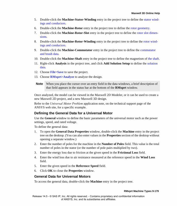
Maxwell 3D Online Help
5. Double-click the Machine-Stator-Winding entry in the project tree to define the stator wind-ings and conductors.
6. Double-click the Machine-Rotor entry in the project tree to define the rotor geometry.
7. Double-click the Machine-Rotor-Slot entry in the project tree to define the rotor slot dimen-sions.
8. Double-click the Machine-Rotor-Winding entry in the project tree to define the rotor wind-ings and conductors.
9. Double-click the Machine-Commutator entry in the project tree to define the commutator and brush data.
10. Double-click the Machine-Shaft entry in the project tree to define the magnetism of the shaft.
11. Right-click Analysis in the project tree, and click Add Solution Setup to define the solution data.
12. Choose File>Save to save the project.
13. Choose RMxprt>Analyze to analyze the design.
Once analyzed, the model can be viewed in the Maxwell 2D Modeler, or it can be used to create a new Maxwell 2D project, and a new Maxwell 3D design.
Refer to the Universal Motor Problem application note, on the technical support page of the ANSYS web site, for a specific example.
Defining the General Data for a Universal Motor
Use the General window to define the basic parameters of the universal motor such as the power settings, speed, and rated voltage.
To define the general data:
1. To open the General Data Properties window, double-click the Machine entry in the project tree on the desktop. (You can also enter values in the Properties section of the desktop without opening a separate window.)
2. Enter the number of poles for the machine in the Number of Poles field. This value is the total number of poles in the stator (or the number of pole pairs multiplied by two).
3. Enter the energy loss due to friction at the given speed in the Frictional Loss field.
4. Enter the wind loss due to air resistance measured at the reference speed in the Wind Loss field.
5. Enter the given speed in the Reference Speed field.
6. Click OK to close the Properties window.
General Data for Universal Motors
To access the general data, double-click the Machine entry in the project tree.
Note When you place the cursor over an entry field in the data windows, a brief description of that field appears in the status bar at the bottom of the RMxprt window.
RMxprt Machine Types 9-179
Release 14.5 - © SAS IP, Inc. All rights reserved. - Contains proprietary and confidential information of ANSYS, Inc. and its subsidiaries and affiliates.

Maxwell 3D Online Help
The General Data Properties window for a three-phase induction motor contains the following fields:
Defining the Stator Data for a Universal MotorUse the Stator Properties windows to define the stator dimensions, slots, windings, and conduc-tors.
The stator is the outer lamination stack where the polyphase voltage windings reside.
To define the general stator data:
1. To open the Stator Data Properties window, double-click the Machine>Stator entry in the project tree on the desktop. (You can also enter values in the Properties section of the desktop without opening a separate window.)
2. Enter the Outer Diameter of the stator.
3. Enter the overall width of the stator outer profile in the Overall Width field.
4. Enter the Inner Diameter of the stator.
5. Enter the length of the stator core in the Length field.
6. Enter the stacking factor for the stator core in the Stacking Factor field.
7. Select a Steel Type for the stator core:
a. Click the button for Steel Type.The Select Definition window appears.
b. Select a steel type from the list, or define a new steel type.
c. Click OK to close the Select Definition window and return to the Properties window.
8. Click OK to close the Properties window.
Stator Data for Universal MotorsTo access the general stator data, double-click the Machine>Stator entry in the project tree.
The Stator Data Properties window contains the following fields:
Machine Type The machine type you selected when inserting a new RMxprt design (Switched Reluctance Motor).
Number of Poles Number of poles for this machine.
Frictional Loss The frictional energy loss (due to friction) measured at the reference speed.
Wind Loss The wind loss (due to air resistance) measured at the reference speed.
Reference Speed The given speed of reference.
Outer Diameter The outer diameter of the stator core.
Overall Width The overall width of the stator outer profile.
Inner Diameter The inner diameter of the stator core.
9-180 RMxprt Machine Types
Release 14.5 - © SAS IP, Inc. All rights reserved. - Contains proprietary and confidential information of ANSYS, Inc. and its subsidiaries and affiliates.

Maxwell 3D Online Help
Defining the Stator Pole for a Universal MotorThe rotor pole drives the electromagnetic field which is coupled with the stator windings. Use the s Stator Pole Data Properties window to define the stator pole.
To define the rotor pole:
1. To open the Stator Pole Data Properties window, double-click the Machine-Stator-Pole entry in the project tree on the desktop. (You can also enter values in the Properties section of the desktop without opening a separate window.)
2. Enter the ratio of the actual arc distance in relation to the maximum possible arc distance in the Embrace field. This value is between 0 and 1.
3. Enter the distance from the center of the stator to the magnet arc center in the Offset field.
Length The length of the stator core.
Stacking Factor The effective magnetic length of the stator core.
Steel Type The steel type of the stator core. Click the button to open the Select Definition window.
Note For a two-pole machine, a pole embrace of 0.75 yields a magnet with a span of 135 degrees (based on 0.75*180 degrees).
RMxprt Machine Types 9-181
Release 14.5 - © SAS IP, Inc. All rights reserved. - Contains proprietary and confidential information of ANSYS, Inc. and its subsidiaries and affiliates.

Maxwell 3D Online Help
Enter 0 for a uniform air gap.
4. Enter the minimum pole width in the PoleWidth field.
5. Enter the yoke thickness in the Ty field.
6. Enter the shoe-tip thickness in the Ts field.
7. Enter the pole’s hole radius in the R1 field. If there is no hole in the design, enter 0.
8. Enter the pole’s side fillet radius in the R2 field.
9. Enter the radius of the pole’s center side fillet arcs in the R3 field.
10. Enter the radius of the shoe connecting arc in the R4 field. To auto-design this dimension, enter 0. For a linear connection, enter 0.
MagnetRadius
Offset
Rotor ODRadius
9-182 RMxprt Machine Types
Release 14.5 - © SAS IP, Inc. All rights reserved. - Contains proprietary and confidential information of ANSYS, Inc. and its subsidiaries and affiliates.
Maxwell 3D Online Help
11. Enter the inner radius of the screw hole between the two poles in the R5 field. If there is no hole in the design, enter 0.
12. Enter the outer radius of the screw hole between the two poles in the R6 field. If there is no hole in the design, enter 0.
13. Click OK to close the Properties window.
Stator Pole Data for Universal Motors
To access the stator pole data, double-click the Machine-Stator-Pole entry in the project tree.
The Stator Pole Data Properties window contains the following fields:
Defining the Stator Windings and Conductors for a Universal MotorTo define the stator windings and conductors:
1. To open the Stator Winding Properties window, double-click the Machine-Stator-Winding entry in the project tree on the desktop. (You can also enter values in the Properties section of the desktop without opening a separate window.)
2. Enter the thickness of the insulation between the stator core and the field winding in the Insu-lation Thickness field.
3. Enter the end length adjustment of the stator coils in the End Adjustment field. The end adjustment is the distance one end of the conductor extends vertically beyond the end of the
Embrace The pole embrace.
Offset The pole-arc center offset from the stator center (0 for a uniform air gap).
PoleWidth The minimum pole width.
Ty The yoke thickness.
Ts The shoe-tip thickness.
R1 The hole radius in the pole (0 for no hole).
R2 The radius of the pole side fillet.
R3 The radius of the center of the pole side fillet arcs.
R4 The radius of the shoe connecting arc (0 for auto-design or for a linear connection).
R5 The inner radius of the screw hole between two poles (0 for no hole).
R6 The outer radius of the screw hole between two poles (0 for no hole).
RMxprt Machine Types 9-183
Release 14.5 - © SAS IP, Inc. All rights reserved. - Contains proprietary and confidential information of ANSYS, Inc. and its subsidiaries and affiliates.
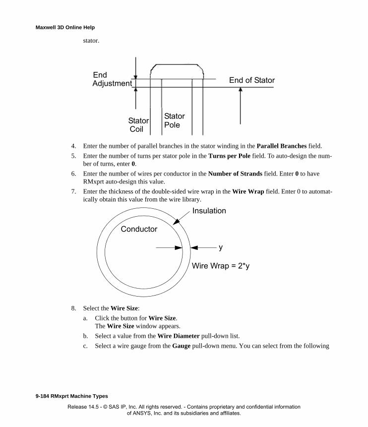
Maxwell 3D Online Help
stator.
4. Enter the number of parallel branches in the stator winding in the Parallel Branches field.
5. Enter the number of turns per stator pole in the Turns per Pole field. To auto-design the num-ber of turns, enter 0.
6. Enter the number of wires per conductor in the Number of Strands field. Enter 0 to have RMxprt auto-design this value.
7. Enter the thickness of the double-sided wire wrap in the Wire Wrap field. Enter 0 to automat-ically obtain this value from the wire library.
8. Select the Wire Size:
a. Click the button for Wire Size.The Wire Size window appears.
b. Select a value from the Wire Diameter pull-down list.
c. Select a wire gauge from the Gauge pull-down menu. You can select from the following
EndAdjustment
StatorCoil
End of Stator
StatorPole
Insulation
Conductor
y
Wire Wrap = 2*y
9-184 RMxprt Machine Types
Release 14.5 - © SAS IP, Inc. All rights reserved. - Contains proprietary and confidential information of ANSYS, Inc. and its subsidiaries and affiliates.

Maxwell 3D Online Help
options:
The gauge number is based on AWG settings. You can create your own wire table using Machine>Wire, and then you can select this wire table using the Tools>Options>Machine Options command.
d. When you are done setting the wire size, click OK to close the Wire Size window and return to the Properties window.
9. Enter the thickness of the wedge insulation in the Wedge Thickness field.
10. Enter the thickness of the insulation layer in the Layer Insulation field.
11. Enter the limited slot fill factor for the wire design in the Limited Fill Factor field.
12. Click OK to close the Properties window.
Defining Different Size Wires for a Universal Motor Stator WindingTo define different size wires:
1. In the Wire Size window, select MIXED from the Gauge pull-down menu.
2. Select either Round or Rectangular as the Wire Type.
3. Enter the appropriate wire data in the table:
• For a round wire:
• Enter the Diameter in the table.
• Enter a Number in the table to specify how many of the conductor’s wires have this diameter.
• For a rectangular wire:
• Enter the Width of the wire in the table.
• Enter the Thickness of the wire in the table.
• Enter the Fillet value in the table.
• Enter a Number in the table to specify how many of the conductor’s wires have this data.
4. Click Add to add the new wire data.
5. Repeat steps 3 and 4 for each size wire you want to add.
<number>You can select a specific gauge number. When you select a gauge number, the Wire Diameter field is automatically updated.
USERThis option allows you to manually enter the Wire Diameter. This is useful when you want to enter a diameter that does not correspond to a particular wire gauge.
AUTO
This option sets the Wire Diameter to zero, and RMxprt automatically calculates the optimal value. The diameter information is then written to the output file when you analyze the design.
MIXED
This option allows you to define a conductor that is made of different size wires. For example, a single conductor may consist of 5 wires, 3 wires with a diameter of 0.21mm and 2 with a diameter of 0.13mm.
RMxprt Machine Types 9-185
Release 14.5 - © SAS IP, Inc. All rights reserved. - Contains proprietary and confidential information of ANSYS, Inc. and its subsidiaries and affiliates.
Maxwell 3D Online Help
6. When you are finished defining the wires, click OK to close the Wire Size window and return to the RMxprt Properties window.
Stator Winding Data for Universal Motors
To access the stator winding data, double-click the Machine-Stator-Winding entry in the project tree.
The Stator Winding Data Properties window contains the following fields:
Defining the Rotor Data for a Universal Motor
The rotor is equipped with slots containing copper conductors that are connected to the commuta-tor. The commutator acts as a mechanical rectifier in the motor.
The rotor consists of copper bars in which current is induced by the magnetic fields produced by the stator windings. In the project tree, double-click Machine>Rotor and Machine-Rotor-Pole to define the rotor and the pole.
To define general stator data:
1. To open the Rotor Data Properties window, double-click the Machine>Rotor entry in the project tree on the desktop. (You can also enter values in the Properties section of the desktop without opening a separate window.)
2. Enter the stacking factor for the rotor core in the Stacking Factor field. This value relates to the effective magnetic length of the core, and ranges from 0 to 1. It is defined as the total length
Note For example, if one conductor is made up of 5 wires, and 3 of those wires have a diameter of 0.21mm, and the other 2 have a diameter of 0.13mm, then the mixed wire size table will have two lines. The first line will list Diameter = 0.21 and Number = 3. The second line will list Diameter = 0.13 and Number = 2. An equivalent wire diameter is displayed as Wire Size value in the Winding tab in the Properties window.
Insulation Thickness
The thickness of the insulation between the stator core and the field winding.
End Adjustment The end length adjustment of the stator coils, which is the distance one end of the conductor extends vertically beyond the end of the stator.
Parallel Branches The number of parallel branches in the stator winding.
Turns per Pole The number of turns per stator pole (0 for auto-design).
Number of Strands
The number of wires per conductor (0 for auto-design).
Wire Wrap The thickness of the double-sided wire wrap (0 to automatically obtain this value from the wire library).
Wire Size The diameter of the wire (0 for auto-design). Click the button to open the Wire Size window where you can specify units, wire type, diameter, and gauge.
9-186 RMxprt Machine Types
Release 14.5 - © SAS IP, Inc. All rights reserved. - Contains proprietary and confidential information of ANSYS, Inc. and its subsidiaries and affiliates.

Maxwell 3D Online Help
minus the total insulation from the laminations, divided by the total length. A value of 1 indi-cates that the rotor is not laminated.
3. Enter the number of slots in the rotor core in the Number of Slots field.
4. Select a Slot Type:
a. Click the button.The Select Slot Type window appears.
b. Click a button to select the desired pole type (1, 2, 3, 4, 5, or 6). Though slots 3 and 4 are visually similar, they differ in how the edges are constructed. Slot 3 has a tapered edge leading from the slot opening to the main slot body. Slot 4 has a rounded edge at the same location, where the quantity Hr1 defines the radius of the corner slot. TIP: When you run the mouse over each option, the diagram changes to show that pole type.
c. Click OK to close the Select Slot Type window and return to the Properties window.
Optionally, check User Defined Slot if you wish to define the slot dimensions using the Slot Editor.
5. Enter the outer diameter of the rotor core in the Outer Diameter field.
6. Enter the inner diameter of the rotor core in the Inner Diameter field.
7. Enter the length of the rotor core in the Length field.
8. Select a Steel Type for the rotor core:
a. Click the button for Steel Type.The Select Definition window appears.
b. Select a steel type from the list, or define a new steel type.
c. Click OK to close the Select Definition window and return to the Properties window.
9. Enter the number of slots in the skew width in the Skew Width field.
10. Click OK to close the Properties window.
Rotor Data for Universal Motors
To access the general rotor data, double-click the Machine>Rotor entry in the project tree.
The Rotor Data Properties window contains the following fields:
Stacking Factor The effective magnetic length of the rotor core.
Number of Slots The number of slots in the rotor core.
Slot Type The rotor core slot type. Click the button to open the Select Slot Type window and select from the following types: 1, 2, 3, 4, 5, 6.
Outer Diameter The outer diameter of the rotor core.
Inner Diameter The inner diameter of the rotor core.
Length The length of the rotor core.
Steel Type The steel type of the rotor core. Click the button to open the Select Definition window.
Skew Width The skew width measured in slot number.
RMxprt Machine Types 9-187
Release 14.5 - © SAS IP, Inc. All rights reserved. - Contains proprietary and confidential information of ANSYS, Inc. and its subsidiaries and affiliates.

Maxwell 3D Online Help
Defining the Rotor Slots for Universal Motors
To define the physical dimensions of the rotor slots:
1. To open the Rotor Slot Data Properties window, double-click the Machine-Rotor-Slot entry in the project tree on the desktop. (You can also enter values in the Properties section of the desktop without opening a separate window.)
2. Optionally, to automatically design the dimensions of slots Hs2, Bs1, and Bs2, select the Auto Design check box. Using this option causes the software to converge to a flux density value of 1.5 Tesla in the rotor teeth.
3. Enter the available slot dimensions. The following dimensions may be listed, depending on the Slot Type selected and depending on whether or not Auto Design is selected.:
4. Click OK to close the Properties window.
Rotor Slot Data for Universal MotorsTo access the rotor slot data, double-click the Machine-Rotor-Slot entry in the project tree.
The Rotor Slot Data Properties window contains the following fields:
Hs0 Always available.
Hs1 Always available.
Hs2 Available only when Auto Design is cleared. When Auto Design is selected, this slot dimension is determined automatically.
Bs0 Always available.
Bs1 Available only when Auto Design is cleared. When Auto Design is selected, this slot dimension is determined automatically. When Parallel Tooth is selected, this slot dimension is determined based on the value entered in the Tooth Width field.
Bs2 Available only when Auto Design is cleared. When Auto Design is selected, this slot dimension is determined automatically. When Parallel Tooth is selected, this slot dimension is determined based on the value entered in the Tooth Width field.
Rs Always available. Rs is added when the slot type is 3 or 4.
Auto Design Select or clear this to enable or disable auto-design of slots Hs2, Bs1, and Bs2. When this check box is selected, only two other fields appear in the window: Hs0 and Bs0.
Parallel Tooth
Select this to design Bs1 and Bs2 based on the tooth width. When this check box is selected, the Bs1 and Bs2 fields are removed, and the Tooth Width field is added.
Tooth WidthThe tooth width for the parallel tooth, on which Bs1 and Bs2 are designed.
Hs0 A slot dimension (see the diagram shown in the modeling window when Machine-Rotor-Slot is selected).
Hs1 A slot dimension (see the diagram shown in the modeling window when Machine-Rotor-Slot is selected).
9-188 RMxprt Machine Types
Release 14.5 - © SAS IP, Inc. All rights reserved. - Contains proprietary and confidential information of ANSYS, Inc. and its subsidiaries and affiliates.

Maxwell 3D Online Help
Defining the Rotor Windings and Conductors for a Universal MotorTo define the rotor windings, wires, and conductors:
1. To open the Rotor Slot Winding Properties window, double-click the Machine-Rotor-Winding entry in the project tree on the desktop. (You can also enter values in the Properties section of the desktop without opening a separate window.)
2. Click the Winding tab.
3. Select a Winding Type:
a. Click the button for Winding Type.The Winding Type window appears.
b. Select from one of the following three types of winding:
• Lap
• Wave
• Frog Leg
4. Enter the number of windings in the Multiplex Number field (1 for a single winding, 2 for double windings, 3 for triple windings). For a lap winding, the multiplex number is the number of commutators between the start and end of one winding, and the number of parallel branches is equal to the number of poles multiplied by the multiplex number. For a wave winding, the
Hs2 A slot dimension (see the diagram shown in the modeling window when Machine-Rotor-Slot is selected).
Bs0 A slot dimension (see the diagram shown in the modeling window when Machine-Rotor-Slot is selected).
Bs1 A slot dimension (see the diagram shown in the modeling window when Machine-Rotor-Slot is selected).
Bs2 A slot dimension (see the diagram shown in the modeling window when Machine-Rotor-Slot is selected).
Rs A slot dimension (see the diagram shown in the modeling window when Machine-Rotor-Slot is selected).
Rs A slot dimension. (see the diagram shown in the modeling window when Machine-Stator-Slot is selected). Rs is added when the slot type is 3 or 4.
RMxprt Machine Types 9-189
Release 14.5 - © SAS IP, Inc. All rights reserved. - Contains proprietary and confidential information of ANSYS, Inc. and its subsidiaries and affiliates.
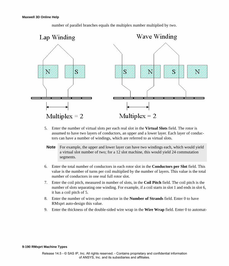
Maxwell 3D Online Help
number of parallel branches equals the multiplex number multiplied by two.
5. Enter the number of virtual slots per each real slot in the Virtual Slots field. The rotor is assumed to have two layers of conductors, an upper and a lower layer. Each layer of conduc-tors can have a number of windings, which are referred to as virtual slots.
6. Enter the total number of conductors in each rotor slot in the Conductors per Slot field. This value is the number of turns per coil multiplied by the number of layers. This value is the total number of conductors in one real full rotor slot.
7. Enter the coil pitch, measured in number of slots, in the Coil Pitch field. The coil pitch is the number of slots separating one winding. For example, if a coil starts in slot 1 and ends in slot 6, it has a coil pitch of 5.
8. Enter the number of wires per conductor in the Number of Strands field. Enter 0 to have RMxprt auto-design this value.
9. Enter the thickness of the double-sided wire wrap in the Wire Wrap field. Enter 0 to automat-
Note For example, the upper and lower layer can have two windings each, which would yield a virtual slot number of two; for a 12 slot machine, this would yield 24 commutation segments.
9-190 RMxprt Machine Types
Release 14.5 - © SAS IP, Inc. All rights reserved. - Contains proprietary and confidential information of ANSYS, Inc. and its subsidiaries and affiliates.

Maxwell 3D Online Help
ically obtain this value from the wire library.
10. Select the Wire Size:
a. Click the button for Wire Size.The Wire Size window appears.
b. Select a value from the Wire Diameter pull-down list.
c. Select a wire gauge from the Gauge pull-down menu. You can select from the following options:
The gauge number is based on AWG settings. You can create your own wire table using Machine>Wire, and then you can select this wire table using the Tools>Options>Machine Options command.
d. When you are done setting the wire size, click OK to close the Wire Size window and return to the Properties window.
11. Click the End/Insulation tab.
12. Select or clear the Input Half-turn Length check box.
13. Do one of the following:
• If you selected Input Half-turn Length, then enter the half-turn length of the armature winding in the Half Turn Length field.
<number>You can select a specific gauge number. When you select a gauge number, the Wire Diameter field is automatically updated.
USERThis option allows you to manually enter the Wire Diameter. This is useful when you want to enter a diameter that does not correspond to a particular wire gauge.
AUTO
This option sets the Wire Diameter to zero, and RMxprt automatically calculates the optimal value. The diameter information is then written to the output file when you analyze the design.
MIXED
This option allows you to define a conductor that is made of different size wires. For example, a single conductor may consist of 5 wires, 3 wires with a diameter of 0.21mm and 2 with a diameter of 0.13mm.
Insulation
Conductor
y
Wire Wrap = 2*y
RMxprt Machine Types 9-191
Release 14.5 - © SAS IP, Inc. All rights reserved. - Contains proprietary and confidential information of ANSYS, Inc. and its subsidiaries and affiliates.

Maxwell 3D Online Help
• If you cleared Input Half-turn Length, then enter the end length adjustment of the stator coils in the End Adjustment field. The end adjustment is the distance one end of the con-ductor extends vertically beyond the end of the stator.
14. Enter the inner radius of the base corner in the Base Inner Radius field.
15. Enter the inner diameter of the coil tip in the Tip Inner Diameter field.
16. Enter the distance between two rotor coils in the End Clearance field.
17. Enter the thickness of the slot liner insulation in the Slot Liner field.
18. Enter the thickness of the wedge insulation in the Wedge Thickness field.
19. Enter the thickness of the insulation layer in the Layer Insulation field.
EndAdjustment
StatorCoil
End of Stator
SlotInsulation
9-192 RMxprt Machine Types
Release 14.5 - © SAS IP, Inc. All rights reserved. - Contains proprietary and confidential information of ANSYS, Inc. and its subsidiaries and affiliates.

Maxwell 3D Online Help
20. Enter the limited slot fill factor for the wire design in the Limited Fill Factor field.
21. Select the type of equalizer connection from the Equalizer Connection pull-down menu. Select from None, Half, or Full.
22. Click OK to close the Properties window.
Defining Different Size Wires for a Universal Motor Rotor Winding
Use the Gauge option if you have a conductor that is made up different size wires.
To define different size wires:
1. In the Wire Size window, select MIXED from the Gauge pull-down menu.
2. Select either Round or Rectangular as the Wire Type.
3. Enter the appropriate wire data in the table:
• For a round wire:
• Enter the Diameter in the table.
• Enter a Number in the table to specify how many of the conductor’s wires have this diameter.
• For a rectangular wire:
• Enter the Width of the wire in the table.
• Enter the Thickness of the wire in the table.
• Enter the Fillet value in the table.
• Enter a Number in the table to specify how many of the conductor’s wires have this data.
4. Click Add to add the new wire data.
5. Repeat steps 3 and 4 for each size wire you want to add.
6. When you are finished defining the wires, click OK to close the Wire Size window and return to the RMxprt Properties window.
Rotor Winding Data for Universal Motors
To access the stator winding data, double-click the Machine-Rotor-Winding entry in the project tree.
Note For example, if one conductor is made up of 5 wires, and 3 of those wires have a diameter of 0.21mm, and the other 2 have a diameter of 0.13mm, then the mixed wire size table will have two lines. The first line will list Diameter = 0.21 and Number = 3. The second line will list Diameter = 0.13 and Number = 2. An equivalent wire diameter is displayed as Wire Size value in the Winding tab in the Properties window.
RMxprt Machine Types 9-193
Release 14.5 - © SAS IP, Inc. All rights reserved. - Contains proprietary and confidential information of ANSYS, Inc. and its subsidiaries and affiliates.

Maxwell 3D Online Help
The Rotor Winding Data Properties window contains the following fields:
Winding tabWinding Type The type of rotor winding. Click the button to open the Winding Type window and choose from Lap, Wave, and Frog Leg.
Multiplex Number Single, double, or triple windings (1, 2, or 3).
Virtual Slots The number of virtual slots per real slot.
Conductors per Slot
The number of conductors per rotor slot (0 for auto-design).
Coil Pitch The coil pitch measured in number of slots.
Number of Strands
The number of wires per conductor (0 for auto-design).
Wire Wrap The thickness of the double-sided wire wrap (0 to automatically obtain this value from the wire library).
Wire Size The diameter of the wire (0 for auto-design). Click the button to open the Wire Size window where you can specify units, wire type, diameter, and gauge.
End/Insulation tab
Input Half-turn Length
Select or clear this check box to specify whether or not you want to enter the half-turn length. When this check box is selected, the Half Turn Length field appears the next time you open the Properties window. When this check box is selected, the End Adjustment field appears instead.
Half Turn Length The half-turn length of the armature winding.
End Adjustment The end length adjustment of the rotor coils.
Base Inner Radius The inner radius of the base corner.
Tip Inner Diameter
The inner diameter of the coil tip.
End Clearance The end clearance between two adjacent coils.
Slot Liner The thickness of the slot liner insulation.
Wedge Thickness The thickness of the wedge insulation.
Layer Insulation The thickness of the insulation layer.
9-194 RMxprt Machine Types
Release 14.5 - © SAS IP, Inc. All rights reserved. - Contains proprietary and confidential information of ANSYS, Inc. and its subsidiaries and affiliates.

Maxwell 3D Online Help
Defining the Commutator and Brush for a Universal MotorThe commutator allows current transfer between DC terminals or brushes and the rotor coils, pro-viding the current to the system as a function of rotation. Due to the action of the commutator, the corresponding magnetic field has a fixed distribution with respect to the stator.
To define the commutator and brush pairs:
1. To open the Commutator Data Properties window, double-click the Machine>Commuta-tor entry in the project tree on the desktop. (You can also enter values in the Properties sec-tion of the desktop without opening a separate window.)
2. Click the Commutator tab.
3. Select Cylinder or Pancake Type as the Commutator Type.
4. For Cylinder commutators, do the following:
a. Enter the Commutator Diameter.
b. Enter the Commutator Length.
5. For Pancake commutators, do the following:
a. Enter the Outer Diameter.
b. Enter the Inner Diameter.
6. Enter the thickness of the insulation between two consecutive commutator segments in the Commutator Insulation field.
Limited Fill FactorThe limited slot fill factor for the wire design.
Equalizer Connection
The connection type of the equalizer. Select from None, Half, or Full.
Note When you place the mouse cursor over the commutator type, an outline of the commutator appears.
RMxprt Machine Types 9-195
Release 14.5 - © SAS IP, Inc. All rights reserved. - Contains proprietary and confidential information of ANSYS, Inc. and its subsidiaries and affiliates.

Maxwell 3D Online Help
7. Click the Brush tab.
8. Enter the Brush Width.
9. Enter the Brush Length.
10. Enter the number of brush pairs when using a wave armature winding in the Brush Pairs field.
11. Enter the angle of displacement from the neutral axis, in mechanical degrees, in the Brush Dis-placement field.
12. Enter the voltage drop across one brush pair in the Brush Drop field.
13. Enter the mechanical pressure of the brushes as they press against the commutator in the Brush Press field.
14. Enter the Frictional Coefficient of the brush.
15. Click OK to close the Properties window.
Commutator and Brush Data for Universal MotorsTo access the commutator and brush data, double-click the Machine>Commutator entry in the project tree.
The Commutator Data Properties window contains the following fields:
Note The brush displacement is positive for the counter-clockwise direction. For example, if the rotor turns clockwise and the brush displacement is also clockwise, then the angle is negative; if the rotor turns clockwise but the brush displacement is counter-clockwise, then the angle is positive.
Note If the Friction Loss field is used in the General window, the Brush Press and Frictional Coefficient fields will be hidden in the Commutator/Brush window. These fields are shown only when the Friction Loss field in the General window is set to zero.
Commutator tab
Commutator Type The type of commutator. Click the button to open the Select Commutator Type window and select from Cylinder or Pancake.
Commutator Diameter
For a Cylinder commutator type, the diameter of the commutator.
Commutator Length
For a Cylinder commutator type, the length of the commutator.
Outer Diameter For a Pancake commutator type, the outer diameter of the commutator.
Inner Diameter For a Pancake commutator type, the inner diameter of the commutator.
Commutator Insulation
The thickness of the insulation between the two commutator bars.
9-196 RMxprt Machine Types
Release 14.5 - © SAS IP, Inc. All rights reserved. - Contains proprietary and confidential information of ANSYS, Inc. and its subsidiaries and affiliates.

Maxwell 3D Online Help
Defining the Shaft Data for a Universal Motor
To define the shaft:
1. To open the Shaft Data Properties window, double-click the Machine>Shaft entry in the project tree on the desktop. (You can also enter values in the Properties section of the desktop without opening a separate window.)
2. Select or clear the Magnetic Shaft check box to specify whether or not the shaft is to be made of magnetic material.
3. Click OK to close the Properties window.
Shaft Data for Universal Motors
To access the shaft data, double-click the Machine>Shaft entry in the project tree.
The Shaft Data Properties window contains the following fields:
Setting Up Analysis Parameters for a Universal MotorTo define the solution data:
1. To open the Solution Setup window, right-click Analysis in the project tree, and click Add Solution Setup.
2. Click the General tab. The Operation Type is automatically set to Motor for this machine type.
3. Select the Load Type used in the motor from the following options:
Brush tab Brush Width The width of the brush.
Brush Length The length of the brush.
Brush Pairs The number of brush pairs.
Brush Displacement
The displacement of the brush from the neutral position, in mechanical degrees (positive for anti-rotating direction).
Brush Drop The voltage drop across a one-pair brush.
Brush Press The brush press per unit area. (Available only when Frictional Loss is set to zero for the machine.)
Frictional Coefficient
The frictional coefficient of the brush. (Available only when Frictional Loss is set to zero for the machine.)
Magnetic Shaft Select or clear this check box to indicate whether or not the shaft is made of magnetic material.
Const Speed The speed remains constant in the motor.
Const Power The output power remains constant in the motor.
RMxprt Machine Types 9-197
Release 14.5 - © SAS IP, Inc. All rights reserved. - Contains proprietary and confidential information of ANSYS, Inc. and its subsidiaries and affiliates.

Maxwell 3D Online Help
4. Enter the output power developed at the shaft of the motor in the Rated Output Power field.
5. Enter the RMS line-to-line voltage in the Rated Voltage field.
6. Enter the desired output speed of the motor at the load point in the Rated Speed field.
7. Enter the temperature at which the system functions in the Operating Temperature field.
8. Click the Universal Motor tab.
9. Enter the Frequency, and select the units.
10. Click OK to close the Solution Setup window.
Related Topics:
Solution Data for Universal Motors
Solution Data for Universal Motors
To access the solution data, right-click Analysis in the project tree, and click Add Solution Setup. For this machine type, there is only one tab, the General tab.
The Solution Setup window contains the following fields:
Related Topics:
Setting Up Analysis Parameters for a Universal Motor
Const Torque The torque remains constant regardless of the speed. In this case, Tload = Trated, given by the output power divided by the given rated speed.
Linear Torque The torque increases linearly with speed. In this case, Tload = Trated * (n/nrated) where Trated is given by the output power divided by the given rated speed.
Fan Load The load varies nonlinearly with speed. In this case, Tload = Trated * (n/nrated)2 where Trated is given by the output power divided by the given rated speed.
Operation Type General tab. The operation type is automatically set to Motor for this machine type.
Load Type General tab. Select from Const Speed, Const Power, Const Torque, Linear Torque, and Fan Load. The default is Const Power.
Rated Output Power
General tab. Type a value for the rated output voltage, and select the units.
Rated Voltage General tab. Type a value for the rated voltage, and select the units.
Rated Speed General tab. Type a value for the rated speed, and select the units.
Operating Temperature
General tab. Type a value for the operating temperature, and select the units.
Frequency Universal Motor tab. Enter a frequency in the Frequency field, and select the units.
9-198 RMxprt Machine Types
Release 14.5 - © SAS IP, Inc. All rights reserved. - Contains proprietary and confidential information of ANSYS, Inc. and its subsidiaries and affiliates.
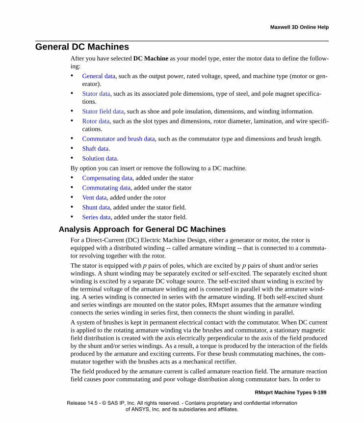
Maxwell 3D Online Help
General DC MachinesAfter you have selected DC Machine as your model type, enter the motor data to define the follow-ing:
• General data, such as the output power, rated voltage, speed, and machine type (motor or gen-erator).
• Stator data, such as its associated pole dimensions, type of steel, and pole magnet specifica-tions.
• Stator field data, such as shoe and pole insulation, dimensions, and winding information.
• Rotor data, such as the slot types and dimensions, rotor diameter, lamination, and wire specifi-cations.
• Commutator and brush data, such as the commutator type and dimensions and brush length.
• Shaft data.
• Solution data.
By option you can insert or remove the following to a DC machine.
• Compensating data, added under the stator
• Commutating data, added under the stator
• Vent data, added under the rotor
• Shunt data, added under the stator field.
• Series data, added under the stator field.
Analysis Approach for General DC MachinesFor a Direct-Current (DC) Electric Machine Design, either a generator or motor, the rotor is equipped with a distributed winding -- called armature winding -- that is connected to a commuta-tor revolving together with the rotor.
The stator is equipped with p pairs of poles, which are excited by p pairs of shunt and/or series windings. A shunt winding may be separately excited or self-excited. The separately excited shunt winding is excited by a separate DC voltage source. The self-excited shunt winding is excited by the terminal voltage of the armature winding and is connected in parallel with the armature wind-ing. A series winding is connected in series with the armature winding. If both self-excited shunt and series windings are mounted on the stator poles, RMxprt assumes that the armature winding connects the series winding in series first, then connects the shunt winding in parallel.
A system of brushes is kept in permanent electrical contact with the commutator. When DC current is applied to the rotating armature winding via the brushes and commutator, a stationary magnetic field distribution is created with the axis electrically perpendicular to the axis of the field produced by the shunt and/or series windings. As a result, a torque is produced by the interaction of the fields produced by the armature and exciting currents. For these brush commutating machines, the com-mutator together with the brushes acts as a mechanical rectifier.
The field produced by the armature current is called armature reaction field. The armature reaction field causes poor commutating and poor voltage distribution along commutator bars. In order to
RMxprt Machine Types 9-199
Release 14.5 - © SAS IP, Inc. All rights reserved. - Contains proprietary and confidential information of ANSYS, Inc. and its subsidiaries and affiliates.

Maxwell 3D Online Help
improve commutating, commutating poles and winding can be equipped between two adjacent main poles and compensating winding can be equipped under main poles.
The performance of a DC machine is computed by DC analysis.
DC Machine Operating as a Motor
The voltage equation of a DC motor is
where, Ub is the voltage drop of one-pair brushes, R1 is the total series resistance of the armature branch, E is the back emf as given below:
where CEf and CEs, which depend on the saturation of the magnetic field, are the back-emf coeffi-cients in ohm.s/rad, is the rotor speed in mechanical rad/s, and If and Ia are the exciting currents of the shunt and series windings, respectively.
For a given speed, armature current can be computed based on the terminal voltage U, as shown below:
The shaft torque is computed from:
where CTf and CTs are the torque coefficients in Nm/A^2 which are numerically the same as CEf and CEs, respectively. Tfw is the frictional and wind torque. The output power (mechanical power) is
The input power (electrical power) is
U E Ub R1 Ia⋅+( )+=
E CEf ω If⋅ ⋅ CEs ω Ia⋅ ⋅+=
Ia
U Ub– CEf– ω If⋅ ⋅
R1 CEs+ ω⋅--------------------------------------------------=
T2 CTf If⋅ CTs+ Ia⋅( ) Ia⋅ Tfw–=
P2 T2 ω⋅=
P1 P2 Pfw PCua Pb PFe+ + +( )+=
9-200 RMxprt Machine Types
Release 14.5 - © SAS IP, Inc. All rights reserved. - Contains proprietary and confidential information of ANSYS, Inc. and its subsidiaries and affiliates.
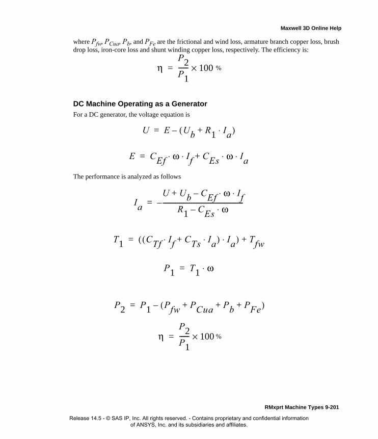
Maxwell 3D Online Help
where Pfw, PCua, Pb, and PFe are the frictional and wind loss, armature branch copper loss, brush drop loss, iron-core loss and shunt winding copper loss, respectively. The efficiency is:
DC Machine Operating as a GeneratorFor a DC generator, the voltage equation is
The performance is analyzed as follows
ηP2P1------ 100×= %
U E Ub R1 Ia⋅+( )–=
E CEf ω If⋅ ⋅ CEs ω Ia⋅ ⋅+=
Ia
U Ub CEf–+ ω If⋅ ⋅
R1 CEs– ω⋅---------------------------------------------------–=
T1 CTf If⋅ CTs+ Ia⋅( ) Ia⋅( ) Tfw+=
P1 T1 ω⋅=
P2 P1 Pfw PCua Pb PFe+ + +( )–=
ηP2P1------ 100×= %
RMxprt Machine Types 9-201
Release 14.5 - © SAS IP, Inc. All rights reserved. - Contains proprietary and confidential information of ANSYS, Inc. and its subsidiaries and affiliates.

Maxwell 3D Online Help
Defining a General DC MachineThe general procedure for defining a a general DC machine is as follows:
1. Insert a DC machine into a new or existing project.
2. Double-click the Machine entry in the project tree to define the general data.
3. Double-click the Machine-Stator entry in the project tree to define the stator geometry.
4. Double-click the Machine-Stator-Pole entry in the project tree to define the stator pole dimensions.
5. Double-click the Machine-Stator-Field entry in the project tree to define the stator windings, conductors, and insulation data.
6. Double-click the Machine-Rotor entry in the project tree to define the general rotor geometry, the pole data, and the insulation data.
7. Double-click the Machine-Rotor-Slot entry in the project tree to define the rotor slot dimen-sions.
8. Double-click the Machine-Rotor-Winding entry in the project tree to define the rotor conduc-tors and windings.
9. Double-click the Machine-Commutator entry in the project tree to define the commutator and brush data.
10. Double-click the Machine-Shaft entry in the project tree to define the magnetism of the shaft.
11. Right-click Analysis in the project tree, and click Add Solution Setup to define the solution data.
12. Choose File>Save to save the project.
13. Choose RMxprt>Analyze to analyze the design.
Once analyzed, the model can be viewed in the Maxwell 2D Modeler, or it can be used to create a new Maxwell 2D project, and a new Maxwell 3D design.
Refer to the DC Machine application note, on the technical support page of the ANSYS web site, for a specific example of a problem using a DC machine. (IS THERE ONE?)
Defining the General Data for a General DC MachineUse the General window to define the basic parameters of the DC motor, such as the power set-tings, speed, and rated voltage.
To define the general data:
1. To open the General Data Properties window, double-click the Machine entry in the project tree on the desktop. (You can also enter values in the Properties section of the desktop without opening a separate window.)
2. Enter the number of poles for the machine in the Number of Poles field. This value is the total number of poles in the stator (or the number of pole pairs multiplied by two).
Note When you place the cursor over an entry field, a brief description of that field appears in the status bar at the bottom of the RMxprt window.
9-202 RMxprt Machine Types
Release 14.5 - © SAS IP, Inc. All rights reserved. - Contains proprietary and confidential information of ANSYS, Inc. and its subsidiaries and affiliates.

Maxwell 3D Online Help
3. Enter the energy loss due to friction at the given speed in the Frictional Loss field.
4. Enter the wind loss due to air resistance measured at the reference speed in the Wind Loss field.
5. Enter the given speed in the Reference Speed field.
6. Click OK to close the Properties window.
General Data for General DC Machines
To access the general data, double-click the Machine entry in the project tree.
The General Data Properties window for a three-phase induction motor contains the following fields:
Defining the Stator Data for a General DC MachineUse the Stator Properties windows to define the stator dimensions, slots, windings, and conduc-tors.
The stator is the outer lamination stack where the polyphase voltage windings reside.
To define the general stator data:
1. To open the Stator Data Properties window, double-click the Machine>Stator entry in the project tree on the desktop. (You can also enter values in the Properties section of the desktop without opening a separate window.)
2. Enter the maximum diameter for a polygon-type frame in the Frame Outer Diameter field.
3. Enter the minimum outer width for a polygon-type frame in the Frame Overall Width field.
4. Enter the Frame Thickness.
5. Enter the Frame Length.
6. Select a steel type for the frame:
a. Click the button for Frame Material.The Select Definition window appears.
b. Select a steel type from the list, or define a new steel type.
c. Click OK to close the Select Definition window and return to the Properties window.
7. Select a Pole Type:
a. Click the button.The Select Pole Type window appears.
Machine Type The machine type you selected when inserting a new RMxprt design (DC Machine).
Number of Poles The number of poles the machine contains.
Frictional Loss The frictional energy loss (due to friction) measured at the reference speed.
Wind Loss The wind loss (due to air resistance) measured at the reference speed.
Reference Speed The given speed of reference.
RMxprt Machine Types 9-203
Release 14.5 - © SAS IP, Inc. All rights reserved. - Contains proprietary and confidential information of ANSYS, Inc. and its subsidiaries and affiliates.

Maxwell 3D Online Help
b. Click a button to specify the desired field type (either 1 or 2).
c. Click OK to close the Select Pole Type window and return to the Properties window.
8. Enter the length of the stator main pole in the Pole Length field.
9. Enter the effective magnetic length for the stator main pole in the Pole Stacking Factor field.
10. Select a steel type for the stator main pole:
a. Click the button for Pole Material.The Select Definition window appears.
b. Select a steel type from the list, or define a new steel type.
c. Click OK to close the Select Definition window and return to the Properties window.
11. Enter the thickness of the pole press boards in the Press Board Thickness field.
12. If the pole press board is made of magnetic material, then select the Magnetic Press Board check box.
13. Click OK to close the Properties window.
Stator Data for General DC Machines
To access the general stator data, double-click the Machine>Stator entry in the project tree.
The Stator Data Properties window contains the following fields:
Frame Outer Diameter
The maximum diameter for a polygon-type frame.
Frame Overall Width
The minimum outer width for a polygon-type frame.
Frame Thickness The thickness of the frame.
Frame Length The length of the frame.
Frame Material The steel type of the frame. Click the button to open the Select Definition window.
Pole Type The pole type of the stator. Click the button to open the Select Pole Type window and select from the following two types: 1 and 2.
Pole Length The length of the stator main pole.
Pole Stacking Factor
The stacking factor of the stator main pole.
Pole Material The steel type of the stator main pole. Click the button to open the Select Definition window.
Press Board Thickness
The thickness of the pole press boards.
Magnetic Press Board
Whether or not the pole press board is made of magnetic material.
9-204 RMxprt Machine Types
Release 14.5 - © SAS IP, Inc. All rights reserved. - Contains proprietary and confidential information of ANSYS, Inc. and its subsidiaries and affiliates.

Maxwell 3D Online Help
Defining the Stator Pole for a General DC MachineThe rotor pole drives the electromagnetic field which is coupled with the stator windings. Use the s Stator Pole Data Properties window to define the stator pole.
To define the rotor pole:
1. To open the Stator Pole Data Properties window, double-click the Machine-Stator-Pole entry in the project tree on the desktop. (You can also enter values in the Properties section of the desktop without opening a separate window.)
2. Enter the inner diameter at the pole center in the Dmin field.
3. Enter the diameter at the pole tip in the Dmax field.
4. Enter the width of the pole arc with a uniform air gap in the Bp0 field. For an eccentric air gap, enter 0.
5. Enter the width of the pole tip in the Bp1 field.
6. Enter the maximum width of the pole shoe in the Bp2 field. This field is only available for a Pole Type of 1.
7. Enter the minimum width of the pole shoe in the Bp3 field. This field is only available for a Pole Type of 1.
8. Enter the size of the pole shoe fillet in the Rp0 field. THis field is only available for a Pole Type of 2.
9. Enter the fillet between the pole shoe and the pole body in the Rp1 field. THis field is only available for a Pole Type of 2.
10. Enter the pole shoe height in the Hp field.
11. Enter the pole body width in the Bm field.
12. Click OK to close the Properties window.
Stator Pole Data for General DC Machines
To access the stator pole data, double-click the Machine-Stator-Pole entry in the project tree.
The Rotor Pole Data Properties window contains the following fields:
Note For a two-pole machine, a pole embrace of 0.75 yields a magnet with a span of 135 degrees (based on 0.75*180 degrees).
Dmin The inner diameter at the pole center.
Dmax The diameter at the pole tip.
Bp0 The width of the pole arc with a uniform air gap (0 for an eccentric air gap).
Bp1 The width of the pole tip.
Bp2 The maximum width of the pole shoe. For pole type 1.
Bp3 The minimum width of the pole shoe. FOr pole type 1.
Rp0 The pole shoe fillet. For pole type 2.
RMxprt Machine Types 9-205
Release 14.5 - © SAS IP, Inc. All rights reserved. - Contains proprietary and confidential information of ANSYS, Inc. and its subsidiaries and affiliates.

Maxwell 3D Online Help
Defining the Stator Field Data for a General DC MachineTo define the stator windings and insulation data:
1. To open the Stator Field Properties window, double-click the Machine-Stator-Field entry in the project tree on the desktop. (You can also enter values in the Properties section of the desktop without opening a separate window.)
2. Enter the thickness of the insulation under the pole shoe in the Shoe Insulation field.
3. Enter the thickness of the insulation at the pole body side in the Pole Insulation field.
4. Enter the minimum gap in the Winding Clearance field. The winding clearance is one of the following: the minimum gap between two field windings, or the minimum gap between a field winding and a commutating winding.
5. Enter the thickness of the insulation between the shunt winding and the series winding in the Winding Insulation field.
6. Select the type of exciting of the series winding to the shunt winding from the Compound Exciting Mode pull-down list. The options are Cumulative and Differential.
7. Click OK to close the Properties window.
Stator Field Data for General DC MachinesTo access the stator field data, double-click the Machine-Stator-Field entry in the project tree.
The Stator Field Data Properties window contains the following fields:
Shunt Data for General DC Machines
By option you can insert or remove a shunt from a General DC Machine. If you insert a shunt, it appears in the project tree under the stator field data.
To insert a shunt.
1. Right click on the Field icon under the stator in the project tree to display the popup menu.
2. Click Insert Shunt.
Rp1 The fillet between the pole shoe and the pole body. For pole type 2.
Hp The height of the pole shoe.
Bm The width of the pole body.
Shoe Insulation The thickness of the insulation under the pole shoe.
Pole Insulation The thickness of the insulation at the pole body side.
Winding Clearance
The minimum air gap between two field windings, or the minimum gap between a field winding and a commutating winding.
Winding Insulation
The thickness of the insulation between the shunt winding and the series winding.
Compound Exciting Mode
The cumulative exciting or differential exciting of the series winding to the shunt winding. Select Cumulative or Differential from the pull-down list.
9-206 RMxprt Machine Types
Release 14.5 - © SAS IP, Inc. All rights reserved. - Contains proprietary and confidential information of ANSYS, Inc. and its subsidiaries and affiliates.

Maxwell 3D Online Help
The Shunt icon appears under the field icon.
To Remove an existing shunt:
1. Right click on the Field icon under the stator in the project tree to display the popup menu.
2. Click Remove Shunt.
The shut is removed from the project tree.
The Shunt data for a General DC Machine contains the following fields.
Series Data for General DC MachinesBy option, you can insert or remove a series from a General DC Machine. If you insert a series, it appears in the project tree under the stator field data.
To insert a series:
1. Right click on the Field icon under the stator in the project tree to display the popup menu.
2. Click Insert Series.
The Series icon appears under the field icon.
To Remove an existing series:
1. Right click on the Field icon under the stator in the project tree to display the popup menu.
2. Click Remove Series.
The series is removed from the project tree.
Winding type Specified as Round, Cylinder coil, or Edgewise coil, by clicking the button to display the Winding Type selection window.
Parallel branches Number of parallel branches.
Conductors per pole
Number of conductors per pole. 0 for auto-design. Odd number of strands for the case where the input and output leads are on different sides.
Number of strands
Number of strands (number of wires per conductor). 0 for auto-design.
Wire wrap Double side wire wrap thickness. 0 for auto-pickup in the wire library.
Wire size. Click the button to display the Wire Size selection window.
Axial Clearance Axial gap between field winding and pole body on the inner coil.
Limited cross width
Limited cross section width for winding design or arrangement. 0 for available maximum area.
Limited cross height
Limited cross section height for winding design or arrangement. 0 for available maximum area.
Winding fillet.
RMxprt Machine Types 9-207
Release 14.5 - © SAS IP, Inc. All rights reserved. - Contains proprietary and confidential information of ANSYS, Inc. and its subsidiaries and affiliates.

Maxwell 3D Online Help
The Series data for a General DC Machine contains the following fields.
Compensating Data for General DC MachinesBy option, you can insert or remove Compensating for a General DC Machine.
To insert compensating:
1. Right-click on the Stator icon to display the pop-up menu.
2. Click Insert Compensating.
To remove an existing Compensating:
1. Right click on the Stator icon to display the pop-up menu.
2. Click Remove Compensating.
To access the data for compensating inserted to a General DC Machine, double click on the Machine-Rotor-Compensating item in the project tree.
The Compensating properties window contains the following fields.
Winding type Specified as Round, Cylinder coil, or Edgewise coil, by clicking the button to display the Winding Type selection window.
Parallel branches Number of parallel branches.
Conductors per pole
Number of conductors per pole. 0 for auto-design. Odd number of strands for the case where the input and output leads are on different sides.
Number of strands
Number of strands (number of wires per conductor). 0 for auto-design.
Wire wrap Double side wire wrap thickness. 0 for auto-pickup in the wire library.
Wire size. Click the button to display the Wire Size selection window.
Axial Clearance Axial gap between field winding and pole body on the inner coil.
Limited cross width
Limited cross section width for winding design or arrangement. 0 for available maximum area.
Limited cross height
Limited cross section height for winding design or arrangement. 0 for available maximum area.
Winding fillet.
Slots per pole Number of slots per pole for the compensating winding.
Bc0 Opening width of the compensating slots.
Hc0 Opening height of the compensating slots.
Bc2 Width of the compensating slots.
Hc2 Height of the compensating slots.
Parallel branches Number of parallel branches.
9-208 RMxprt Machine Types
Release 14.5 - © SAS IP, Inc. All rights reserved. - Contains proprietary and confidential information of ANSYS, Inc. and its subsidiaries and affiliates.

Maxwell 3D Online Help
Commutating Data for General DC Machines
Commutating must be inserted under the stator by right-clicking on the stator icon to display the pop-up menu, and click Insert Commutating command. This command also inserts an icon in the project tree for an associated winding.
To remove an existing Commutating (and associated winding), right-click on the stator icon to dis-play the pop-up menu and click Remove Commutating. This removes the commutating and the associated winding.
Note: This is distinct from the general Commutator data associated with rotor.
Conductors per slot
Number of conductors per slot for the compensating windings
Number of strands
Number of strands (number of wires per conductor), 0 for auto-design.
Wire wrap Double-side wire wrap thickness, 0 for auto pickup in the wire library
Rectangle wire Whether to use round (the default) or rectangle wire.
Wire size Click the button to display the Wire Size window to specify the wire diameter and gauge.
Slot liner Insulation slot liner thickness
End adjustment one side end length adjustment of a conductor.
Pole width Width of the commutating poles
Pole height Height of the commutating poles.
Pole length Length of the commutating poles
Shoe width Shoe width of the commutating poles
Shoe height Shoe height of the commutating poles.
Second air gap Length of the second air gap between the commutating pole and the frame.
Pole stacking factor
Stacking factor for the commutating poles.
Pole material Steel type of the commutating poles. Click the button to display the Select Definition window.
Pole insulation Thickness of insulation on the pole body side.
RMxprt Machine Types 9-209
Release 14.5 - © SAS IP, Inc. All rights reserved. - Contains proprietary and confidential information of ANSYS, Inc. and its subsidiaries and affiliates.

Maxwell 3D Online Help
Winding Data for Commutating
If you have inserted commutating for a General DC machine, an additional winding icon appears in the project tree for the associated winding.
Defining the Rotor Data for a General DC Machine
The rotor is equipped with slots containing copper conductors that are connected to the commuta-tor. The commutator acts as a mechanical rectifier in the motor.
The rotor consists of copper bars in which current is induced by the magnetic fields produced by the stator windings. In the project tree, double-click Machine>Rotor and Machine-Rotor-Pole to define the rotor and the pole.
To define general stator data:
1. To open the Rotor Data Properties window, double-click the Machine>Rotor entry in the project tree on the desktop. (You can also enter values in the Properties section of the desktop without opening a separate window.)
2. Enter the stacking factor for the rotor core in the Stacking Factor field. This value relates to the effective magnetic length of the core, and ranges from 0 to 1. It is defined as the total length minus the total insulation from the laminations, divided by the total length. A value of 1 indi-cates that the rotor is not laminated.
3. Enter the number of slots in the rotor core in the Number of Slots field.
4. Select a Slot Type:
a. Click the button.
Winding type Specified as Round, Cylinder coil, or Edgewise coil, by clicking the button to display the Winding Type selection window.
Parallel branches Number of parallel branches.
Conductors per pole
Number of conductors per pole. 0 for auto-design. Odd number of strands for the case where the input and output leads are on different sides.
Number of strands
Number of strands (number of wires per conductor). 0 for auto-design.
Wire wrap Double side wire wrap thickness. 0 for auto-pickup in the wire library.
Wire size. Click the button to display the Wire Size selection window.
Axial Clearance Axial gap between field winding and pole body on the inner coil.
Limited cross width
Limited cross section width for winding design or arrangement. 0 for available maximum area.
Limited cross height
Limited cross section height for winding design or arrangement. 0 for available maximum area.
Winding fillet.
9-210 RMxprt Machine Types
Release 14.5 - © SAS IP, Inc. All rights reserved. - Contains proprietary and confidential information of ANSYS, Inc. and its subsidiaries and affiliates.

Maxwell 3D Online Help
The Select Slot Type window appears.
b. Click a button to select the desired slot type (1, 2, 3, 4, 5, or 6). Though slots 3 and 4 are visually similar, they differ in how the edges are constructed. Slot 3 has a tapered edge leading from the slot opening to the main slot body. Slot 4 has a rounded edge at the same location, where the quantity Hr1 defines the radius of the corner slot. TIP: When you run the mouse over each option, the diagram changes to show that pole type.
c. Click OK to close the Select Slot Type window and return to the Properties window.
Optionally, check User Defined Slot if you wish to define the slot dimensions using the Slot Editor.
5. Enter the number of lamination sectors in the Lamination Sectors field.
6. Enter the outer diameter of the rotor core in the Outer Diameter field.
7. Enter the inner diameter of the rotor core in the Inner Diameter field.
8. Enter the length of the rotor core in the Length field.
9. Select a Steel Type for the rotor core:
a. Click the button for Steel Type.The Select Definition window appears.
b. Select a steel type from the list, or define a new steel type.
c. Click OK to close the Select Definition window and return to the Properties window.
10. Enter the thickness of the pole press boards in the Press Board Thickness field.
11. Enter the number of slots in the skew width in the Skew Width field.
12. Click OK to close the Properties window.
Rotor Data for General DC Machines
To access the general rotor data, double-click the Machine>Rotor entry in the project tree.
The Rotor Data Properties window contains the following fields:
Stacking Factor The effective magnetic length of the rotor core.
Number of Slots The number of slots the rotor core contains.
Slot Type The type of slots in the rotor core. Click the button to open the Select Slot Type window.
Lamination Sectors
The number of lamination sectors.
Outer Diameter The outer diameter of the rotor core.
Inner Diameter The inner diameter of the rotor core.
Length The length of the rotor core.
RMxprt Machine Types 9-211
Release 14.5 - © SAS IP, Inc. All rights reserved. - Contains proprietary and confidential information of ANSYS, Inc. and its subsidiaries and affiliates.

Maxwell 3D Online Help
Defining the Rotor Slots for a General DC MachineTo define the physical dimensions of the rotor slots:
1. To open the Rotor Slot Data Properties window, double-click the Machine-Rotor-Slot entry in the project tree on the desktop. (You can also enter values in the Properties section of the desktop without opening a separate window.)
2. Optionally, to automatically design the dimensions of slots Hs2, Bs1, and Bs2, select the Auto Design check box. Using this option causes the software to converge to a flux density value of 1.5 Tesla in the rotor teeth.
3. Enter the available slot dimensions. The following dimensions may be listed, depending on the Slot Type selected and depending on whether or not Auto Design is selected.:
4. Click OK to close the Properties window.
Rotor Slot Data for General DC Machines
To access the rotor slot data, double-click the Machine-Rotor-Slot entry in the project tree.
Steel Type The steel type of the rotor core. Click the button to open the Select Definition window.
Press Board Thickness
The thickness of the pole press boards.
Skew Width The skew width measured in slot number.
Hs0 Always available.
Hs1 Always available.
Hs2 Available only when Auto Design is cleared. When Auto Design is selected, this slot dimension is determined automatically.
Bs0 Always available.
Bs1 Available only when Auto Design is cleared. When Auto Design is selected, this slot dimension is determined automatically. When Parallel Tooth is selected, this slot dimension is determined based on the value entered in the Tooth Width field.
Bs2 Available only when Auto Design is cleared. When Auto Design is selected, this slot dimension is determined automatically. When Parallel Tooth is selected, this slot dimension is determined based on the value entered in the Tooth Width field.
Rs Always available.
9-212 RMxprt Machine Types
Release 14.5 - © SAS IP, Inc. All rights reserved. - Contains proprietary and confidential information of ANSYS, Inc. and its subsidiaries and affiliates.
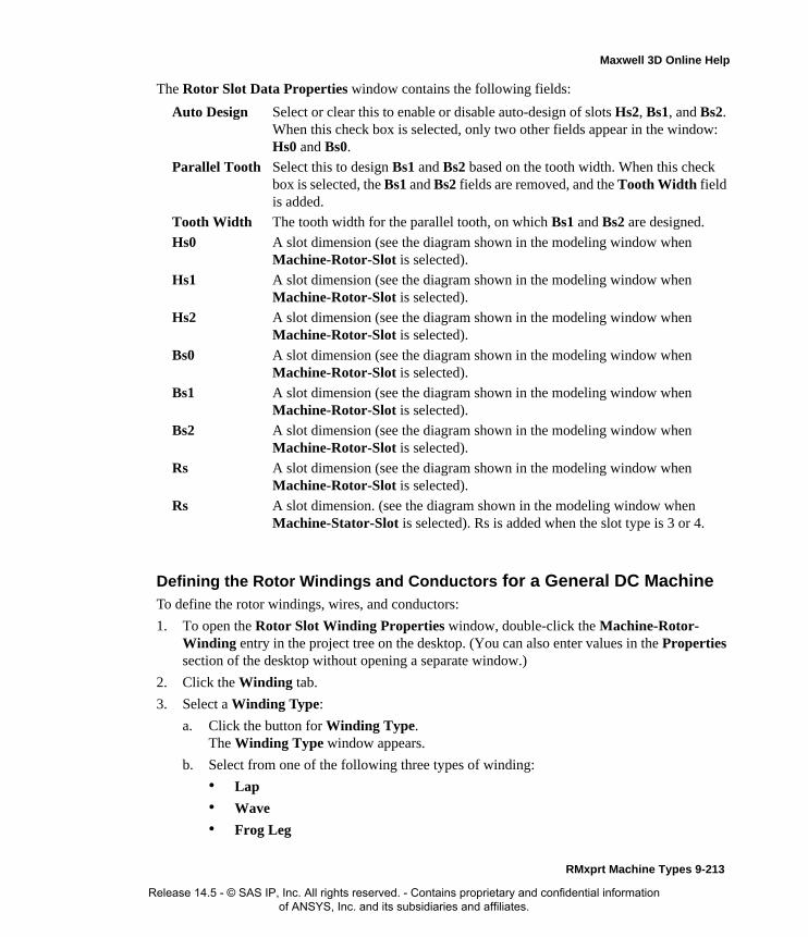
Maxwell 3D Online Help
The Rotor Slot Data Properties window contains the following fields:
Defining the Rotor Windings and Conductors for a General DC MachineTo define the rotor windings, wires, and conductors:
1. To open the Rotor Slot Winding Properties window, double-click the Machine-Rotor-Winding entry in the project tree on the desktop. (You can also enter values in the Properties section of the desktop without opening a separate window.)
2. Click the Winding tab.
3. Select a Winding Type:
a. Click the button for Winding Type.The Winding Type window appears.
b. Select from one of the following three types of winding:
• Lap
• Wave
• Frog Leg
Auto Design Select or clear this to enable or disable auto-design of slots Hs2, Bs1, and Bs2. When this check box is selected, only two other fields appear in the window: Hs0 and Bs0.
Parallel Tooth Select this to design Bs1 and Bs2 based on the tooth width. When this check box is selected, the Bs1 and Bs2 fields are removed, and the Tooth Width field is added.
Tooth Width The tooth width for the parallel tooth, on which Bs1 and Bs2 are designed.
Hs0 A slot dimension (see the diagram shown in the modeling window when Machine-Rotor-Slot is selected).
Hs1 A slot dimension (see the diagram shown in the modeling window when Machine-Rotor-Slot is selected).
Hs2 A slot dimension (see the diagram shown in the modeling window when Machine-Rotor-Slot is selected).
Bs0 A slot dimension (see the diagram shown in the modeling window when Machine-Rotor-Slot is selected).
Bs1 A slot dimension (see the diagram shown in the modeling window when Machine-Rotor-Slot is selected).
Bs2 A slot dimension (see the diagram shown in the modeling window when Machine-Rotor-Slot is selected).
Rs A slot dimension (see the diagram shown in the modeling window when Machine-Rotor-Slot is selected).
Rs A slot dimension. (see the diagram shown in the modeling window when Machine-Stator-Slot is selected). Rs is added when the slot type is 3 or 4.
RMxprt Machine Types 9-213
Release 14.5 - © SAS IP, Inc. All rights reserved. - Contains proprietary and confidential information of ANSYS, Inc. and its subsidiaries and affiliates.

Maxwell 3D Online Help
4. Enter the number of windings in the Multiplex Number field (1 for a single winding, 2 for double windings, 3 for triple windings). For a lap winding, the multiplex number is the number of commutators between the start and end of one winding, and the number of parallel branches is equal to the number of poles multiplied by the multiplex number. For a wave winding, the number of parallel branches equals the multiplex number multiplied by two.
5. Enter the number of virtual slots per each real slot in the Virtual Slots field. The rotor is assumed to have two layers of conductors, an upper and a lower layer. Each layer of conduc-tors can have a number of windings, which are referred to as virtual slots.
6. Enter the total number of conductors in each rotor slot in the Conductors per Slot field. This value is the number of turns per coil multiplied by the number of layers. This value is the total number of conductors in one real full rotor slot.
7. Enter the coil pitch, measured in number of slots, in the Coil Pitch field. The coil pitch is the number of slots separating one winding. For example, if a coil starts in slot 1 and ends in slot 6, it has a coil pitch of 5.
8. Enter the number of wires per conductor in the Number of Strands field. Enter 0 to have RMxprt auto-design this value.
9. Enter the thickness of the double-sided wire wrap in the Wire Wrap field. Enter 0 to automat-
Note For example, the upper and lower layer can have two windings each, which would yield a virtual slot number of two; for a 12 slot machine, this would yield 24 commutation segments.
9-214 RMxprt Machine Types
Release 14.5 - © SAS IP, Inc. All rights reserved. - Contains proprietary and confidential information of ANSYS, Inc. and its subsidiaries and affiliates.

Maxwell 3D Online Help
ically obtain this value from the wire library.
10. Select the Wire Size:
a. Click the button for Wire Size.The Wire Size window appears.
b. Select a value from the Wire Diameter pull-down list.
c. Select a wire gauge from the Gauge pull-down menu. You can select from the following options:
The gauge number is based on AWG settings. You can create your own wire table using Machine>Wire, and then you can select this wire table using the Tools>Options>Machine Options command.
d. When you are done setting the wire size, click OK to close the Wire Size window and return to the Properties window.
11. Click the End/Insulation tab.
12. Select or clear the Input Half-turn Length check box.
13. Do one of the following:
• If you selected Input Half-turn Length, then enter the half-turn length of the armature winding in the Half Turn Length field.
<number>You can select a specific gauge number. When you select a gauge number, the Wire Diameter field is automatically updated.
USERThis option allows you to manually enter the Wire Diameter. This is useful when you want to enter a diameter that does not correspond to a particular wire gauge.
AUTO
This option sets the Wire Diameter to zero, and RMxprt automatically calculates the optimal value. The diameter information is then written to the output file when you analyze the design.
MIXED
This option allows you to define a conductor that is made of different size wires. For example, a single conductor may consist of 5 wires, 3 wires with a diameter of 0.21mm and 2 with a diameter of 0.13mm.
Insulation
Conductor
y
Wire Wrap = 2*y
RMxprt Machine Types 9-215
Release 14.5 - © SAS IP, Inc. All rights reserved. - Contains proprietary and confidential information of ANSYS, Inc. and its subsidiaries and affiliates.

Maxwell 3D Online Help
• If you cleared Input Half-turn Length, then enter the end length adjustment of the stator coils in the End Adjustment field. The end adjustment is the distance one end of the con-ductor extends vertically beyond the end of the stator.
14. Enter the inner radius of the base corner in the Base Inner Radius field.
15. Enter the inner diameter of the coil tip in the Tip Inner Diameter field.
16. Enter the distance between two rotor coils in the End Clearance field.
17. Enter the thickness of the slot liner insulation in the Slot Liner field.
18. Enter the thickness of the wedge insulation in the Wedge Thickness field.
19. Enter the thickness of the insulation layer in the Layer Insulation field.
EndAdjustment
StatorCoil
End of Stator
SlotInsulation
9-216 RMxprt Machine Types
Release 14.5 - © SAS IP, Inc. All rights reserved. - Contains proprietary and confidential information of ANSYS, Inc. and its subsidiaries and affiliates.

Maxwell 3D Online Help
20. Enter the limited slot fill factor for the wire design in the Limited Fill Factor field.
21. Select the type of equalizer connection from the Equalizer Connection pull-down menu. Select from None, Half, or Full.
22. Click OK to close the Properties window.
Defining Different Size Wires for a General DC Machine Rotor Winding
Use the Gauge option if you have a conductor that is made up different size wires.
To define different size wires:
1. In the Wire Size window, select MIXED from the Gauge pull-down menu.
2. Select either Round or Rectangular as the Wire Type.
3. Enter the appropriate wire data in the table:
• For a round wire:
• Enter the Diameter in the table.
• Enter a Number in the table to specify how many of the conductor’s wires have this diameter.
• For a rectangular wire:
• Enter the Width of the wire in the table.
• Enter the Thickness of the wire in the table.
• Enter the Fillet value in the table.
• Enter a Number in the table to specify how many of the conductor’s wires have this data.
4. Click Add to add the new wire data.
5. Repeat steps 3 and 4 for each size wire you want to add.
6. When you are finished defining the wires, click OK to close the Wire Size window and return to the RMxprt Properties window.
Rotor Winding Data for General DC Machines
To access the rotor winding data, double-click the Machine-Rotor-Winding entry in the project tree.
Note For example, if one conductor is made up of 5 wires, and 3 of those wires have a diameter of 0.21mm, and the other 2 have a diameter of 0.13mm, then the mixed wire size table will have two lines. The first line will list Diameter = 0.21 and Number = 3. The second line will list Diameter = 0.13 and Number = 2. An equivalent wire diameter is displayed as Wire Size value in the Winding tab in the Properties window.
RMxprt Machine Types 9-217
Release 14.5 - © SAS IP, Inc. All rights reserved. - Contains proprietary and confidential information of ANSYS, Inc. and its subsidiaries and affiliates.

Maxwell 3D Online Help
The Rotor Winding Data Properties window contains the following fields:
Winding tabWinding Type The type of rotor winding. Click the button to open the Winding Type window and choose from Lap, Wave, and Frog Leg.
Multiplex Number Single, double, or triple windings (1, 2, or 3).
Virtual Slots The number of virtual slots per real slot.
Conductors per Slot
The number of conductors per rotor slot (0 for auto-design).
Coil Pitch The coil pitch measured in number of slots.
Number of Strands
The number of wires per conductor (0 for auto-design).
Wire Wrap The thickness of the double-sided wire wrap (0 to automatically obtain this value from the wire library).
Wire Size The diameter of the wire (0 for auto-design). Click the button to open the Wire Size window where you can specify units, wire type, diameter, and gauge.
End/Insulation tab
Input Half-turn Length
Select or clear this check box to specify whether or not you want to enter the half-turn length. When this check box is selected, the Half Turn Length field appears the next time you open the Properties window. When this check box is selected, the End Adjustment field appears instead.
Half Turn Length The half-turn length of the armature winding.
End Adjustment The end length adjustment of the rotor coils.
Base Inner Radius The inner radius of the base corner.
Tip Inner Diameter
The inner diameter of the coil tip.
End Clearance The end clearance between two adjacent coils.
Slot Liner The thickness of the slot liner insulation.
Wedge Thickness The thickness of the wedge insulation.
Layer Insulation The thickness of the insulation layer.
9-218 RMxprt Machine Types
Release 14.5 - © SAS IP, Inc. All rights reserved. - Contains proprietary and confidential information of ANSYS, Inc. and its subsidiaries and affiliates.

Maxwell 3D Online Help
Vent Data for General DC MachinesBy option, you can insert or remove Vent data for general DC machines. If you have inserted a Vent, the icon appears under the rotor winding in the project tree.
To insert a vent:
1. Right-click on the rotor icon to display the pop-up menu.
2. Click Insert Vent.
To remove an existing vent:
1. Right click on the Stator icon to display the pop-up menu.
2. Click Remove Vent.
The Vent Data Properties window contains the following fields.
Limited Fill FactorThe limited slot fill factor for the wire design.
Equalizer Connection
The connection type of the equalizer. Select from None, Half, or Full.
Vent Ducts Number of radial vent ducts
Duct Width Width of radial vent ducts
Magnetic Spacer Width
Width of magnetic spacer which hold vent ducts. 0 for non-magnetic spacer.
Duct Pitch Vent ducts
Holes per Row Number of axial vent holes per row
Inner Hole Diameter
Diameter of vent holes in inner row.
Outer Hole Diameter
Diameter of vent holes in outer row.
RMxprt Machine Types 9-219
Release 14.5 - © SAS IP, Inc. All rights reserved. - Contains proprietary and confidential information of ANSYS, Inc. and its subsidiaries and affiliates.

Maxwell 3D Online Help
Defining the Commutator and Brush for a General DC MachineThe commutator allows current transfer between DC terminals or brushes and the rotor coils, pro-viding the current to the system as a function of rotation. Due to the action of the commutator, the corresponding magnetic field has a fixed distribution with respect to the stator.
To define the commutator and brush pairs:
1. To open the Commutator Data Properties window, double-click the Machine>Commuta-tor entry in the project tree on the desktop. (You can also enter values in the Properties sec-tion of the desktop without opening a separate window.)
2. Click the Commutator tab.
3. Select Cylinder or Pancake Type as the Commutator Type.
4. For Cylinder commutators, do the following:
a. Enter the Commutator Diameter.
b. Enter the Commutator Length.
5. For Pancake commutators, do the following:
a. Enter the Outer Diameter.
b. Enter the Inner Diameter.
6. Enter the thickness of the insulation between two consecutive commutator segments in the Commutator Insulation field.
7. Click the Brush tab.
8. Enter the Brush Width.
9. Enter the Brush Length.
10. Enter the number of brush pairs when using a wave armature winding in the Brush Pairs field.
11. Enter the angle of displacement from the neutral axis, in mechanical degrees, in the Brush Dis-
Inner Hole Location
Center-to-center diameter of inner row hole vents.
Outer Hole Location
Center-to-center diameter of outer row hole vents.
Banding Slots Number of axial banding slots to tight the rotor winding.
Width of Banding Slots
Width of axial banding slots
Depth of Banding Slots
Depth of axial banding slots
Note When you place the mouse cursor over the commutator type, an outline of the commutator appears.
9-220 RMxprt Machine Types
Release 14.5 - © SAS IP, Inc. All rights reserved. - Contains proprietary and confidential information of ANSYS, Inc. and its subsidiaries and affiliates.
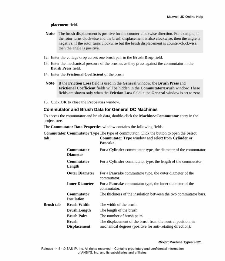
Maxwell 3D Online Help
placement field.
12. Enter the voltage drop across one brush pair in the Brush Drop field.
13. Enter the mechanical pressure of the brushes as they press against the commutator in the Brush Press field.
14. Enter the Frictional Coefficient of the brush.
15. Click OK to close the Properties window.
Commutator and Brush Data for General DC Machines
To access the commutator and brush data, double-click the Machine>Commutator entry in the project tree.
The Commutator Data Properties window contains the following fields:
Note The brush displacement is positive for the counter-clockwise direction. For example, if the rotor turns clockwise and the brush displacement is also clockwise, then the angle is negative; if the rotor turns clockwise but the brush displacement is counter-clockwise, then the angle is positive.
Note If the Friction Loss field is used in the General window, the Brush Press and Frictional Coefficient fields will be hidden in the Commutator/Brush window. These fields are shown only when the Friction Loss field in the General window is set to zero.
Commutator tab
Commutator Type The type of commutator. Click the button to open the Select Commutator Type window and select from Cylinder or Pancake.
Commutator Diameter
For a Cylinder commutator type, the diameter of the commutator.
Commutator Length
For a Cylinder commutator type, the length of the commutator.
Outer Diameter For a Pancake commutator type, the outer diameter of the commutator.
Inner Diameter For a Pancake commutator type, the inner diameter of the commutator.
Commutator Insulation
The thickness of the insulation between the two commutator bars.
Brush tab Brush Width The width of the brush.
Brush Length The length of the brush.
Brush Pairs The number of brush pairs.
Brush Displacement
The displacement of the brush from the neutral position, in mechanical degrees (positive for anti-rotating direction).
RMxprt Machine Types 9-221
Release 14.5 - © SAS IP, Inc. All rights reserved. - Contains proprietary and confidential information of ANSYS, Inc. and its subsidiaries and affiliates.

Maxwell 3D Online Help
Defining the Shaft Data for a General DC Machine
To define the shaft:
1. To open the Shaft Data Properties window, double-click the Machine>Shaft entry in the project tree on the desktop. (You can also enter values in the Properties section of the desktop without opening a separate window.)
2. Select or clear the Magnetic Shaft check box to specify whether or not the shaft is to be made of magnetic material.
3. Select or clear the No Fan check box to specify whether or not the machine contains a ventila-tion fan.
4. If you cleared the No Fan check box, then do the following:
a. Enter the outer diameter of the ventilation fan in the Fan Diameter field.
b. Enter the width of the fan blades in the Blade Width field.
5. Click OK to close the Properties window.
Shaft Data for General DC MachinesTo access the shaft data, double-click the Machine>Shaft entry in the project tree.
The Shaft Data Properties window contains the following fields:
Setting Up Analysis Parameters for a General DC MachineTo define the solution data:
1. To open the Solution Setup window, right-click Analysis in the project tree, and click Add Solution Setup.
2. Click the General tab. The Operation Type is automatically set to Motor for this machine
Brush Drop The voltage drop across a one-pair brush.
Brush Press The brush press per unit area. (Available only when Frictional Loss is set to zero for the machine.)
Frictional Coefficient
The frictional coefficient of the brush. (Available only when Frictional Loss is set to zero for the machine.)
Magnetic Shaft Select or clear this check box to indicate whether or not the shaft is made of magnetic material. When it is selected, the shaft is magnetic.
No Fan Select or clear this check box to indicate whether or not the shaft has a ventilation fan. When it is selected, no fan is being used. When it is cleared, the design uses a fan, and two additional fields appear: Fan Diameter and Blade Width.
Fan Diameter The outer diameter of the ventilation fan.
Blade Width The width of the ventilation fan’s blades.
9-222 RMxprt Machine Types
Release 14.5 - © SAS IP, Inc. All rights reserved. - Contains proprietary and confidential information of ANSYS, Inc. and its subsidiaries and affiliates.

Maxwell 3D Online Help
type.
3. Select the Load Type used in the motor from the following options:
4. Enter the output power in the Rated Output Power field.
5. Enter the applied or output rated DC voltage in the Rated Voltage field.
6. Enter the given rated speed in the Rated Speed field.
7. Enter the temperature at which the system functions in the Operating Temperature field.
8. Click the DC Machine tab.
9. Select one of the following from the Field Exciting Type pull-down list:
• Separately Excited
• Self Excited
10. Enter the Exciting Voltage, and select the units.
11. Enter the Series Resistance, and select the units.
12. To automatically obtained the Exciting Voltage and Series Resistance via the Rated Speed, rather than entering their values, then select the Determined by Rated Speed check box.
13. Click OK to close the Solution Setup window.
Related Topics:
Solution Data for General DC Machines
Solution Data for General DC Machines
To access the solution data, right-click Analysis in the project tree, and click Add Solution Setup. For this machine type, there is only one tab, the General tab.
Const Speed The speed remains constant in the motor.
Const Power The output power remains constant in the motor.
Const Torque The torque remains constant regardless of the speed. In this case, Tload = Trated, given by the output power divided by the given rated speed.
Linear Torque The torque increases linearly with speed. In this case, Tload = Trated * (n/nrated) where Trated is given by the output power divided by the given rated speed.
Fan Load The load varies nonlinearly with speed. In this case, Tload = Trated * (n/nrated)2 where Trated is given by the output power divided by the given rated speed.
RMxprt Machine Types 9-223
Release 14.5 - © SAS IP, Inc. All rights reserved. - Contains proprietary and confidential information of ANSYS, Inc. and its subsidiaries and affiliates.

Maxwell 3D Online Help
The Solution Setup window contains the following fields:
Related Topics:
Setting Up Analysis Parameters for a General DC Machine
Operation Type General tab. Select Motor or Generator from the pull-down list.
Load Type On the General tab. For a motor, select from Const Speed, Const Power, Const Torque, Linear Torque, and Fan Load. The default is Const Power. For a generator, select from Infinite Bus and Independent Generator.
Rated Output Power
General tab. Type a value for the rated output voltage, and select the units.
Rated Voltage General tab. Type a value for the rated voltage, and select the units.
Rated Speed General tab. Type a value for the rated speed, and select the units.
Operating Temperature
General tab. Type a value for the operating temperature, and select the units.
Field Exciting Type
DC Machine tab. Select Separately Excited or Self Excited from the pull-down list.
Determined by Rated Speed
Select this check box to automatically calculate the Exciting Voltage and the Series Resistance from the Rated Speed, rather than entering the values.
Exciting Voltage Enter a voltage value in the field, and select the units from the pull-down list.
Series Resistance Enter a resistance value in the field, and select the units from the pull-down list.
9-224 RMxprt Machine Types
Release 14.5 - © SAS IP, Inc. All rights reserved. - Contains proprietary and confidential information of ANSYS, Inc. and its subsidiaries and affiliates.

Maxwell 3D Online Help
Claw-Pole AlternatorsAfter you have selected Claw-Pole Alternators as your model type, enter the motor data to define the following:
• General data, such as the output power, rated voltage, and speed.
• Stator data.
• Stator slot data.
• Stator winding data.
• Rotor data, such as the slot types and dimensions, rotor diameter, and lamination.
• Rotor pole data.
• Shaft data.
• Solution data.
Analysis Approach for Claw-Pole AlternatorsClaw-pole alternators (or claw-pole synchronous generators) are widely used in auto industry. They receive mechanical energy at the shaft and transform it into electrical energy.
The stator of a claw-pole alternator is equipped with a polyphase winding. The rotor is comprised of claw poles with the same pole number as the stator winding. The claw poles of the rotor are mag-netized by a cylinder winding and/or a cylinder permanent magnet. The spinning rotor creates a rotating magnetic field in the air gap, which produces induced voltage in the stator winding.
The performance of a claw-pole alternator is analyzed based on the frequency-domain phasor dia-gram, as shown in the figure below.
If a claw-pole alternator is equipped with a permanent magnet, the d-axis armature reactance Xad and q-axis armature reactance Xaq are about constant. Otherwise, Xad is a linearized nonlinear
O
I
I d
I q
U
IR1
jI Xaq
jI q Xaq
E 0 jI d Xad
M
N
jI X1
RMxprt Machine Types 9-225
Release 14.5 - © SAS IP, Inc. All rights reserved. - Contains proprietary and confidential information of ANSYS, Inc. and its subsidiaries and affiliates.
Maxwell 3D Online Help
parameter, and Xaq is a linear parameter. The d-axis synchronous reactance Xd and q-axis synchro-nous reactance Xq are calculated directly from the following:
Rotor Equipped with an Excitation WindingIf the rotor is equipped with an excitation winding, the exciting current can be adjusted, and the d- and the q-axis currents are obtained based on the following process.
Take the input voltage U as the reference phasor, let the power factor angle be f, then the current phasor is
The phasor represented by OM can be expressed as
The phasor represented by OM can be used to determine the direction of E0.
Let denote the power angle (the angle that U lags E0), then the angle that I lags E0 is
The d- and the q-axis currents are obtained as follows
In the phasor diagrams, the phasor length ON represents the d-axis back emf due to the d-axis resultant flux linkage and is used to determine the d-axis field saturation. From the no-load charac-teristic curve of the magnetic circuit, E0, Xad and the excitation current If can be determined based on the frozen method.
Rotor Equipped with a Permanent Magnet Only
If the rotor is equipped with a permanent magnet only, the field excitation can not be adjusted, and the d- and the q-axis currents are obtained based on the following process.
Xd X1 Xad+=
Xq X1 Xaq+=
OM U I R1 jXq+( )+=
θ
Ψ ϕ θ+=
Id I ψsin=
Iq I ψcos=
9-226 RMxprt Machine Types
Release 14.5 - © SAS IP, Inc. All rights reserved. - Contains proprietary and confidential information of ANSYS, Inc. and its subsidiaries and affiliates.

Maxwell 3D Online Help
For a given power angle (the angle that U lags E0), we have
Solving for Id and Iq yields.
Let the angle that I lags E0 be , we have
The power factor angle f (the angle that I lags U) is
Power and Efficiency
The output electric power is
θ
IdXd IqR1+ U θcos E0–( )–=
IdR1– IqXq+ U θsin=
Id
Xq U θcos E0–( ) R1U θsin–
R2
1 XdXq+----------------------------------------------------------------------–=
Iq
R1 U θcos E0–( ) XdU θsin+
R2
1 XdXq+-----------------------------------------------------------------------=
ω
ΨIdIq-----tanh=
ϕ Ψ θ–=
P2 3UI ϕcos=
RMxprt Machine Types 9-227
Release 14.5 - © SAS IP, Inc. All rights reserved. - Contains proprietary and confidential information of ANSYS, Inc. and its subsidiaries and affiliates.

Maxwell 3D Online Help
The input mechanical power is
where Pfw, PCua, PFe, , and PCuf are the frictional and wind, the armature copper, the iron-core, the excitation winding copper (if an excitation winding is equipped) losses, respectively.
The input mechanical torque is
where denotes the synchronous speed in rad/s.
The efficiency of the generator is:
Defining a Claw-Pole AlternatorThe general procedure for defining a claw-pole alternator is as follows:
1. Create the alternator project.
2. Double-click the Machine entry in the project tree to define the general data.
3. Double-click the Machine-Stator entry in the project tree to define the stator geometry.
4. Double-click the Machine-Stator-Slot entry in the project tree to define the stator slot dimen-sions.
5. Double-click the Machine-Stator-Winding entry in the project tree to define the stator wind-ings and conductors.
6. Double-click the Machine-Rotor entry in the project tree to define the rotor geometry.
7. Double-click the Machine-Rotor-Pole entry in the project tree to define the pole, embrace, offset, and air gap data for the rotor pole.
8. Double-click the Machine-Shaft entry in the project tree to define the magnetism of the shaft.
9. Right-click Analysis in the project tree, and click Add Solution Setup to define the solution data.
10. Choose File>Save to save the project.
11. Choose RMxprt>Analyze to analyze the design.
Note When you place the cursor over an entry field in the data windows, a brief description of that field appears in the status bar at the bottom of the RMxprt window.
P1 P2 Pfw PCua PFe PCuf+ + + +=
T1
P1ω------=
ω
ηP2P1------ 100×= %
9-228 RMxprt Machine Types
Release 14.5 - © SAS IP, Inc. All rights reserved. - Contains proprietary and confidential information of ANSYS, Inc. and its subsidiaries and affiliates.

Maxwell 3D Online Help
Once analyzed, the model can be viewed in the Maxwell 2D Modeler, or it can be used to create a new Maxwell 2D project, and new Maxwell 3D design.
Refer to the Claw-Pole Alternator Problem application note, on the technical support page of the ANSYS web site, for a specific example of a permanent-magnet DC motor problem.
Defining the General Data for a Claw-Pole Alternator
Use the General window to define the basic parameters of the alternator, such as the power set-tings, speed, and rated voltage.
To define the general data:
1. To open the General Data Properties window, double-click the Machine entry in the project tree on the desktop. (You can also enter values in the Properties section of the desktop without opening a separate window.)
2. Enter the number of poles for the machine in the Number of Poles field. This value is the total number of poles in the stator (or the number of pole pairs multiplied by two).
3. Enter or select the Number of Phases (2, 3, or 4).
4. Enter the energy loss due to friction at the given speed in the Frictional Loss field.
5. Enter the wind loss due to air resistance measured at the reference speed in the Wind Loss field.
6. Enter the given speed in the Reference Speed field.
7. Click OK to close the Properties window.
General Data for Claw-Pole AlternatorsTo access the general data, double-click the Machine entry in the project tree.
The General Data Properties window for a three-phase induction motor contains the following fields:
Defining the Stator Data for a Claw-Pole AlternatorUse the Stator Properties windows to define the stator dimensions, slots, windings, and conduc-tors.
The stator is the outer lamination stack where the polyphase voltage windings reside.
Machine Type The machine type you selected when inserting a new RMxprt design (Claw-Pole Synchronous Machine).
Frictional Loss The frictional energy loss (due to friction and air resistance) measured at the reference speed.
Number of Poles The number of poles the machine contains.
Number of Phases The number of phases.
Wind Loss The wind loss measured at the reference speed.
Reference Speed The given speed of reference.
RMxprt Machine Types 9-229
Release 14.5 - © SAS IP, Inc. All rights reserved. - Contains proprietary and confidential information of ANSYS, Inc. and its subsidiaries and affiliates.
Maxwell 3D Online Help
To define the general stator data:
1. To open the Stator Data Properties window, double-click the Machine>Stator entry in the project tree on the desktop. (You can also enter values in the Properties section of the desktop without opening a separate window.)
2. Enter the Outer Diameter of the stator.
3. Enter the Inner Diameter of the stator.
4. Enter the length of the stator core in the Length field.
5. Enter the stacking factor for the stator core in the Stacking Factor field. This value is a ratio of he effective magnetic length of the core, and ranges from 0 to 1. The stacking factor is defined as the total length minus the total insulation from the laminations, divided by the total length. A value of 1 indicates that the rotor is not laminated.
6. Select a Steel Type for the stator core:
a. Click the button for Steel Type.The Select Definition window appears.
b. Select a steel type from the list, or define a new steel type.
c. Click OK to close the Select Definition window and return to the Properties window.
7. Enter the Number of Slots in the stator.
8. Select the Slot Type:
a. Click the button for the Slot Type.The Select Slot Type window appears.
b. Select a slot type (available types include 1 through 4).
Optionally, check User Defined Slot if you wish to define the slot dimensions using the Slot Editor.
c. Click OK to close the Select Slot Type window and return to the Properties window.
9. Enter the skew width, measured in slot number, in the Skew Width field.
10. Click OK to close the Properties window.
Stator Data for Claw-Pole Alternators
To access the general stator data, double-click the Machine>Stator entry in the project tree.
The Stator Data Properties window contains the following fields:
Note When you place the mouse cursor over the slot type, a schematic of the selected type appears, displaying the slot dimension variables.
Outer Diameter The outer diameter of the stator core.
Inner Diameter The inner diameter of the stator core.
Length The length of the stator core.
Stacking Factor The stacking factor of the stator core.
9-230 RMxprt Machine Types
Release 14.5 - © SAS IP, Inc. All rights reserved. - Contains proprietary and confidential information of ANSYS, Inc. and its subsidiaries and affiliates.

Maxwell 3D Online Help
Defining the Stator Slot Data for a Claw-Pole AlternatorTo define the stator slots:
1. To open the Stator Slot Data Properties window, double-click the Machine-Stator-Slot entry in the project tree on the desktop. (You can also enter values in the Properties section of the desktop without opening a separate window.)
2. Optionally, to automatically design the dimensions of slots Hs2, Bs1, and Bs2, select the Auto Design check box.
3. Optionally, to design dimensions of slots Bs1 and Bs2 based on the stator tooth width, select the Parallel Tooth check box, and enter a value in the Tooth Width field.
4. Enter the available slot dimensions.
5. Click OK to close the Properties window.
Stator Slot Data for Claw-Pole Alternators
To access the stator slot data, double-click the Machine-Stator-Slot entry in the project tree.
Steel Type The steel type of the stator core. Click the button to open the Select Definition window.
Number of Slots The number of slots the stator core contains.
Slot Type The type of slots in the stator core. Click the button to open the Select Slot Type window.
Skew Width The skew width measured in slot number.
Hs0 Always available.
Hs2 Available only when Auto Design is cleared. When Auto Design is selected, this slot dimension is determined automatically.
Bs0 Always available.
Bs1 Available only when Auto Design and Parallel Tooth are both cleared. When Auto Design is selected, this slot dimension is determined automatically. When Parallel Tooth is selected, this slot dimension is determined based on the value entered in the Tooth Width field.
Bs2 Available only when Auto Design and Parallel Tooth are both cleared. When Auto Design is selected, this slot dimension is determined automatically. When Parallel Tooth is selected, this slot dimension is determined based on the value entered in the Tooth Width field.
Rs Rs is added when the slot type is 3 or 4.
RMxprt Machine Types 9-231
Release 14.5 - © SAS IP, Inc. All rights reserved. - Contains proprietary and confidential information of ANSYS, Inc. and its subsidiaries and affiliates.
Maxwell 3D Online Help
The Stator Slot Data Properties window contains the following fields:
Defining the Stator Winding Data for a Claw-Pole AlternatorTo define the stator windings and conductors:
1. To open the Stator Slot Winding Properties window, double-click the Machine-Stator-Winding entry in the project tree on the desktop. (You can also enter values in the Properties section of the desktop without opening a separate window.)
2. Click the Winding tab.
3. Enter the number of layers in the stator winding in the Winding Layers field.
4. Select a Winding Type:
a. Click the button for Winding Type.The Winding Type window appears.
b. Select from one of the following three types of winding:
• Whole Coiled
• Half Coiled
• Editor
5. Select or enter the number of parallel branches in one phase of the winding in the Parallel
Auto Design Select or clear this to enable or disable auto-design of slots Hs2, Bs1, and Bs2. When this check box is selected, only two other fields appear in the window: Hs0 and Bs0.
Parallel Tooth
Select this to design Bs1 and Bs2 based on the tooth width. When this check box is selected, the Bs1 and Bs2 fields are removed, and the Tooth Width field is added.
Tooth WidthThe tooth width for the parallel tooth, on which Bs1 and Bs2 are designed.
Hs0 A slot dimension (see the diagram shown in the modeling window when Machine-Stator-Slot is selected).
Hs1 A slot dimension (see the diagram shown in the modeling window when Machine-Stator-Slot is selected).
Hs2 A slot dimension (see the diagram shown in the modeling window when Machine-Stator-Slot is selected).
Bs0 A slot dimension (see the diagram shown in the modeling window when Machine-Stator-Slot is selected).
Bs1 A slot dimension (see the diagram shown in the modeling window when Machine-Stator-Slot is selected).
Bs2 A slot dimension (see the diagram shown in the modeling window when Machine-Stator-Slot is selected).
Rs A slot dimension. (see the diagram shown in the modeling window when Machine-Stator-Slot is selected). Rs is added when the slot type is 3 or 4.
9-232 RMxprt Machine Types
Release 14.5 - © SAS IP, Inc. All rights reserved. - Contains proprietary and confidential information of ANSYS, Inc. and its subsidiaries and affiliates.
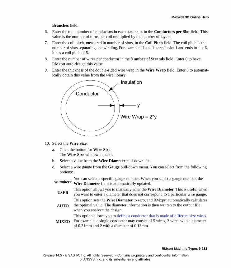
Maxwell 3D Online Help
Branches field.
6. Enter the total number of conductors in each stator slot in the Conductors per Slot field. This value is the number of turns per coil multiplied by the number of layers.
7. Enter the coil pitch, measured in number of slots, in the Coil Pitch field. The coil pitch is the number of slots separating one winding. For example, if a coil starts in slot 1 and ends in slot 6, it has a coil pitch of 5.
8. Enter the number of wires per conductor in the Number of Strands field. Enter 0 to have RMxprt auto-design this value.
9. Enter the thickness of the double-sided wire wrap in the Wire Wrap field. Enter 0 to automat-ically obtain this value from the wire library.
10. Select the Wire Size:
a. Click the button for Wire Size.The Wire Size window appears.
b. Select a value from the Wire Diameter pull-down list.
c. Select a wire gauge from the Gauge pull-down menu. You can select from the following options:
<number>You can select a specific gauge number. When you select a gauge number, the Wire Diameter field is automatically updated.
USERThis option allows you to manually enter the Wire Diameter. This is useful when you want to enter a diameter that does not correspond to a particular wire gauge.
AUTO
This option sets the Wire Diameter to zero, and RMxprt automatically calculates the optimal value. The diameter information is then written to the output file when you analyze the design.
MIXED
This option allows you to define a conductor that is made of different size wires. For example, a single conductor may consist of 5 wires, 3 wires with a diameter of 0.21mm and 2 with a diameter of 0.13mm.
Insulation
Conductor
y
Wire Wrap = 2*y
RMxprt Machine Types 9-233
Release 14.5 - © SAS IP, Inc. All rights reserved. - Contains proprietary and confidential information of ANSYS, Inc. and its subsidiaries and affiliates.

Maxwell 3D Online Help
The gauge number is based on AWG settings. You can create your own wire table using Machine>Wire, and then you can select this wire table using the Tools>Options>Machine Options command.
d. When you are done setting the wire size, click OK to close the Wire Size window and return to the Properties window.
11. Click the End/Insulation tab.
12. Select or clear the Input Half-turn Length check box.
13. Do one of the following:
• If you selected Input Half-turn Length, then enter the half-turn length of the armature winding in the Half Turn Length field.
• If you cleared Input Half-turn Length, then enter the end length adjustment of the stator coils in the End Adjustment field. The end adjustment is the distance one end of the con-ductor extends vertically beyond the end of the stator.
14. Enter the inner radius of the base corner in the Base Inner Radius field.
15. Enter the inner diameter of the coil tip in the Tip Inner Diameter field.
16. Enter the distance between two stator coils in the End Clearance field.
EndAdjustment
StatorCoil
End of Stator
9-234 RMxprt Machine Types
Release 14.5 - © SAS IP, Inc. All rights reserved. - Contains proprietary and confidential information of ANSYS, Inc. and its subsidiaries and affiliates.

Maxwell 3D Online Help
17. Enter the thickness of the slot liner insulation in the Slot Liner field.
18. Enter the thickness of the wedge insulation in the Wedge Thickness field.
19. Enter the thickness of the insulation layer in the Layer Insulation field.
20. Enter the limited slot fill factor for the wire design in the Limited Fill Factor field.
21. Click OK to close the Properties window.
Winding Editor for a Claw-Pole AlternatorFor a claw-pole alternator, you may want to specify a different number of conductors for each stator slot. The Winding Editor makes this possible by enabling you to specify the number of turns for each coil.
To specify the number of turns for each coil:
1. Click Machine>Winding>Edit Layout.The Winding Editor window appears.
2. In the table in the upper left, set which phase you want for each coil and which slot is the “in” and “out” slot for the current in each coil.
3. If you are working on a quarter or half model, you may want to specify a multiplier by clicking the Periodic Multiplier check box and specifying a value.
4. Select or deselect the Constant Turns or Constant Pitch check boxes, depending on whether you want to be able to change these setting in the table above. When these options are selected, you cannot change the turns or pitch.
5. When you are satisfied with the coil settings, click OK to close the Winding Editor window.
SlotInsulation
RMxprt Machine Types 9-235
Release 14.5 - © SAS IP, Inc. All rights reserved. - Contains proprietary and confidential information of ANSYS, Inc. and its subsidiaries and affiliates.

Maxwell 3D Online Help
Defining Different Size Wires for a Claw-Pole Alternator
Use the Gauge option in the Wire Size window if you have a conductor that is made up different size wires.
To define different size wires:
1. In the Wire Size window, select MIXED from the Gauge pull-down menu.
2. Select either Round or Rectangular as the Wire Type.
3. Enter the appropriate wire data in the table:
• For a round wire:
• Enter the Diameter in the table.
• Enter a Number in the table to specify how many of the conductor’s wires have this diameter.
• For a rectangular wire:
• Enter the Width of the wire in the table.
• Enter the Thickness of the wire in the table.
• Enter the Fillet value in the table.
• Enter a Number in the table to specify how many of the conductor’s wires have this data.
4. Click Add to add the new wire data.
5. Repeat steps 3 and 4 for each size wire you want to add.
6. When you are finished defining the wires, click OK to close the Wire Size window and return to the RMxprt Properties window.
Stator Winding Data for Claw-Pole AlternatorsTo access the stator winding data, double-click the Machine-Stator-Winding entry in the project tree.
The Stator Winding Data Properties window contains the following fields:
Note For example, if one conductor is made up of 5 wires, and 3 of those wires have a diameter of 0.21mm, and the other 2 have a diameter of 0.13mm, then the mixed wire size table will have two lines. The first line will list Diameter = 0.21 and Number = 3. The second line will list Diameter = 0.13 and Number = 2. An equivalent wire diameter is displayed as Wire Size value in the Winding tab in the Properties window.
Winding tabWinding Layers The number of winding layers.
Winding Type The type of stator winding. Click the button to open the Winding Type window and choose from Whole Coiled, Half Coiled, and Editor.
Parallel Branches The number of parallel branches in the stator winding.
9-236 RMxprt Machine Types
Release 14.5 - © SAS IP, Inc. All rights reserved. - Contains proprietary and confidential information of ANSYS, Inc. and its subsidiaries and affiliates.

Maxwell 3D Online Help
Conductors per Slot
The number of conductors per stator slot (0 for auto-design).
Coil Pitch The coil pitch measured in number of slots.
Number of Strands
The number of wires per conductor (0 for auto-design).
Wire Wrap The thickness of the double-sided wire wrap (0 to automatically obtain this value from the wire library).
Wire Size The diameter of the wire (0 for auto-design). Click the button to open the Wire Size window where you can specify units, wire type, diameter, and gauge.
End/Insulation tab
Input Half-turn Length
Select or clear this check box to specify whether or not you want to enter the half-turn length. When this check box is selected, the Half Turn Length field appears the next time you open the Properties window. When this check box is selected, the End Adjustment field appears instead.
Half Turn LengthThe half-turn length of the armature winding.
End Adjustment The end length adjustment of the stator coils, which is the distance one end of the conductor extends vertically beyond the end of the stator.
Base Inner Radius
The inner radius of the base corner.
Tip Inner Diameter
The inner diameter of the coil tip.
End Clearance The end clearance between two adjacent coils.
Slot Liner The thickness of the slot liner insulation.
Wedge Thickness The thickness of the wedge insulation.
RMxprt Machine Types 9-237
Release 14.5 - © SAS IP, Inc. All rights reserved. - Contains proprietary and confidential information of ANSYS, Inc. and its subsidiaries and affiliates.

Maxwell 3D Online Help
Defining the Rotor Data for a Claw-Pole AlternatorThe rotor is equipped with slots containing copper conductors that are connected to the commuta-tor. The commutator acts as a mechanical rectifier in the motor.
The rotor consists of copper bars in which current is induced by the magnetic fields produced by the stator windings. In the project tree, double-click Machine-Rotor and Machine-Rotor-Pole to define the rotor and the pole.
To define general rotor data:
1. To open the Rotor Data Properties window, double-click the Machine>Rotor entry in the project tree on the desktop. (You can also enter values in the Properties section of the desktop without opening a separate window.)
2. Enter the outer diameter of the rotor in the Outer Diameter field.
3. Enter the inner diameter of the rotor in the Inner Diameter field.
4. Enter the length of the rotor core in the Length field.
5. Select a Steel Type for the rotor core:
a. Click the button for Steel Type.The Select Definition window appears.
b. Select a steel type from the list, or define a new steel type.
c. Click OK to close the Select Definition window and return to the Properties window.
6. Enter the diameter of the rotor yoke in the Yoke Diameter field.
7. Click OK to close the Properties window.
Layer Insulation The thickness of the insulation layer.
Limited Fill Factor
The limited slot fill factor for the wire design.
9-238 RMxprt Machine Types
Release 14.5 - © SAS IP, Inc. All rights reserved. - Contains proprietary and confidential information of ANSYS, Inc. and its subsidiaries and affiliates.

Maxwell 3D Online Help
Rotor Data for Claw-Pole Alternators
To access the general rotor data, double-click the Machine>Rotor entry in the project tree.
The Rotor Data Properties window contains the following fields:
Defining the Rotor Pole for a Claw-Pole Alternator
The rotor pole drives the electromagnetic field which is coupled with the stator windings. Use the Rotor Pole Data Properties window to define the rotor pole.
To define the rotor pole:
1. To open the Rotor Pole Data Properties window, double-click the Machine-Rotor-Pole entry in the project tree on the desktop. (You can also enter values in the Properties section of the desktop without opening a separate window.)
2. Enter the pole embrace at the pole tip in the Tip Embrace field. This value must be between 0 and 1, exclusive.
3. Enter the pole embrace at the pole root in the Root Embrace field. This value must be between 0 and 2, exclusive.
4. Enter the pole thickness at the pole tip in the Tip Thickness field.
5. Enter the pole thickness at the pole root in the Root Thickness field.
6. Enter the Pole Length.
7. Enter the Slot Depth.
8. Enter the Shoe Thickness.
9. Select the type of magnet to use in the rotor pole from the Magnet Type pull-down menu.
10. If a magnet is being used, enter its length in the Magnet Length field.
11. Enter the width of the second air gap in the Second Air Gap field.
12. Click OK to close the Properties window.
Rotor Pole Data for Claw-Pole Alternators
To access the pole rotor data, double-click the Machine-Rotor-Pole entry in the project tree.
Outer Diameter The outer diameter of the rotor core.
Inner Diameter The inner diameter of the rotor core.
Length The length of the rotor core.
Steel Type The steel type of the rotor core. Click the button to open the Select Definition window.
Yoke Diameter The diameter of the rotor yoke.
Note Some of the fields in the Rotor Pole window change, or are inactive, depending on the Rotor Type you select.
RMxprt Machine Types 9-239
Release 14.5 - © SAS IP, Inc. All rights reserved. - Contains proprietary and confidential information of ANSYS, Inc. and its subsidiaries and affiliates.

Maxwell 3D Online Help
The Rotor Pole Data Properties window contains the following fields:
Defining the Shaft Data for a Claw-Pole AlternatorTo define the shaft:
1. To open the Shaft Data Properties window, double-click the Machine>Shaft entry in the project tree on the desktop. (You can also enter values in the Properties section of the desktop without opening a separate window.)
2. Select or clear the Magnetic Shaft check box to specify whether or not the shaft is to be made of magnetic material.
3. Click OK to close the Properties window.
Shaft Data for Claw-Pole Alternators
To access the shaft data, double-click the Machine>Shaft entry in the project tree.
The Shaft Data Properties window contains the following fields:
Setting Up Analysis Parameters for a Claw-Pole AlternatorTo define the solution data:
1. To open the Solution Setup window, right-click Analysis in the project tree, and click Add Solution Setup.
2. Click the General tab. The Operation Type is automatically set to General for this machine type.
Tip Embrace The pole embrace at the pole tip. Must be > 0 and < 1.
Root Embrace The pole embrace at the pole root. Must be > 0 and < 2.
Tip Thickness The pole thickness at the pole tip.
Root Thickness The pole thickness at the pole root.
Pole Length The length of the pole.
Slot Depth The slot depth.
Shoe Thickness The shoe thickness.
Magnet Type The type of magnet. Click the button to open the Select Definition window. For all pole types.
Magnet Length The length of the magnet (if a magnet is used).
Second Air Gap The width of the second air gap.
Magnetic Shaft Select or clear this check box to indicate whether or not the shaft is made of magnetic material.
9-240 RMxprt Machine Types
Release 14.5 - © SAS IP, Inc. All rights reserved. - Contains proprietary and confidential information of ANSYS, Inc. and its subsidiaries and affiliates.
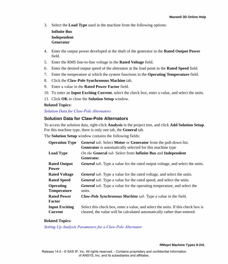
Maxwell 3D Online Help
3. Select the Load Type used in the machine from the following options:
4. Enter the output power developed at the shaft of the generator in the Rated Output Power field.
5. Enter the RMS line-to-line voltage in the Rated Voltage field.
6. Enter the desired output speed of the alternator at the load point in the Rated Speed field.
7. Enter the temperature at which the system functions in the Operating Temperature field.
8. Click the Claw-Pole Synchronous Machine tab.
9. Enter a value in the Rated Power Factor field.
10. To enter an Input Exciting Current, select the check box, enter a value, and select the units.
11. Click OK to close the Solution Setup window.
Related Topics:
Solution Data for Claw-Pole Alternators
Solution Data for Claw-Pole AlternatorsTo access the solution data, right-click Analysis in the project tree, and click Add Solution Setup. For this machine type, there is only one tab, the General tab.
The Solution Setup window contains the following fields:
Related Topics:
Setting Up Analysis Parameters for a Claw-Pole Alternator
Infinite Bus
Independent Generator
Operation Type General tab. Select Motor or Generator from the pull-down list. Generator is automatically selected for this machine type
Load Type On the General tab. Select from Infinite Bus and Independent Generator.
Rated Output Power
General tab. Type a value for the rated output voltage, and select the units.
Rated Voltage General tab. Type a value for the rated voltage, and select the units.
Rated Speed General tab. Type a value for the rated speed, and select the units.
Operating Temperature
General tab. Type a value for the operating temperature, and select the units.
Rated Power Factor
Claw-Pole Synchronous Machine tab. Type a value in the field.
Input Exciting Current
Select this check box, enter a value, and select the units. If this check box is cleared, the value will be calculated automatically rather than entered.
RMxprt Machine Types 9-241
Release 14.5 - © SAS IP, Inc. All rights reserved. - Contains proprietary and confidential information of ANSYS, Inc. and its subsidiaries and affiliates.

Maxwell 3D Online Help
Three-Phase Non-Salient Synchronous Machines (NSSM)After you have selected Three-Phase Non-Salient Synchronous Machine as your model type, enter the data to define the following:
• General data, such as the number of poles, frictional loss, and reference speed.
• Stator pole and winding data, such as its associated pole dimensions, type of steel, and wire definitions.
• Rotor data, such as the slot types and dimensions, rotor diameter, laminations, and windings and conductors.
• Commutator and brush data, such as the commutator dimensions and brush length.
• Shaft data.
• Solution data.
Also see Analysis Approach for the Three-Phase Non-Salient Synchronous Machine
Analysis Approach for Three-Phase Non-Salient Synchronous MachinesThe three-phase non-salient-pole synchronous electric machine has two types: the generator and the motor. Their basic structures are the same. The three-phase non-salient-pole synchronous gen-erators are the main Thrat the shaft and transform it into the electrical energy. The rotor is equipped with a non-salient-pole winding excited by a DC source. The stator is equipped with a three-phase winding that has a sinusoidal spatial distribution. The spinning rotor produces a rotating magnetic field in the air gap of the machine. The frequency of the voltage induced in the stator is given by:
where p is the number of pairs of poles, and n is the mechanical speed of the rotor in rpm, which is called the synchronous speed. The machine is capable of producing both the active and the reactive power as required by the load connected at the stator terminal.
f pn( ) 60⁄=
9-242 RMxprt Machine Types
Release 14.5 - © SAS IP, Inc. All rights reserved. - Contains proprietary and confidential information of ANSYS, Inc. and its subsidiaries and affiliates.

Maxwell 3D Online Help
Usually the frequency-domain phasor diagram is adopted to analyze the characteristics. The phasor diagrams for a generator and a motor are shown.
In the figure, R1, X1, and Xa are the armature resistance, the armature leakage reactance, and the armature reactance, respectively. In a non-salient-pole synchronous machine, Xad ≅ Xaq and they are both expressed by Xa. Taking the input voltage U as the reference phasor, for a given current:
where ϕ is the angle I lags U , which is called the power factor angle.
Generator Motor
I I ϕ–∠=
RMxprt Machine Types 9-243
Release 14.5 - © SAS IP, Inc. All rights reserved. - Contains proprietary and confidential information of ANSYS, Inc. and its subsidiaries and affiliates.

Maxwell 3D Online Help
The internal back EMF induced by the resultant air gap field considering the effects of armature reaction Ei can be derived from:
Based on Ei, the resultant air gap flux considering the effects of armature reaction can be com-puted, and therefore, the magnetic circuit can be solved. With solved magnetic saturation factor, saturated Xa is derived, and therefore, the no-load induced voltage E0 with the same magnetic sat-uration (frozen magnetic circuit) can be calculated from:
Let the angle U legs E0 be θ, which is called the power angle for the generator or the torque angle for the motor, then the angle I lags E0 is
The d- and the q-axis currents can be obtained respectively as follows:
Based on the magnetic circuit solution and E0, Xa and the excitation current If can be determined based on the frozen method.
1. For the generator:
The output power (electric power) is directly computed from the voltage and the current as:
Ei
U R1 jX1+( ) I⋅+
U R1 jX1+( ) I⋅–
=
for Generator
for motor
E0
Ei jXa( ) I⋅+
Ei jXa( ) I⋅–
=for Generator
for motor
ψ ϕ θ+=
IId
Iq
I ψsin
ψcos= =
P2 3UI ϕcos=
9-244 RMxprt Machine Types
Release 14.5 - © SAS IP, Inc. All rights reserved. - Contains proprietary and confidential information of ANSYS, Inc. and its subsidiaries and affiliates.
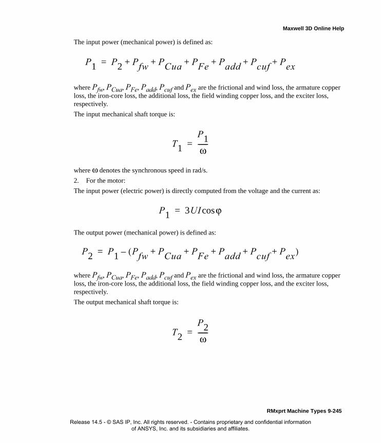
Maxwell 3D Online Help
The input power (mechanical power) is defined as:
where Pfw, PCua, PFe, Padd, Pcuf and Pex are the frictional and wind loss, the armature copper loss, the iron-core loss, the additional loss, the field winding copper loss, and the exciter loss, respectively.
The input mechanical shaft torque is:
where ω denotes the synchronous speed in rad/s.
2. For the motor:
The input power (electric power) is directly computed from the voltage and the current as:
The output power (mechanical power) is defined as:
where Pfw, PCua, PFe, Padd, Pcuf and Pex are the frictional and wind loss, the armature copper loss, the iron-core loss, the additional loss, the field winding copper loss, and the exciter loss, respectively.
The output mechanical shaft torque is:
P1 P2 Pfw PCua PFe Padd Pcuf Pex+ + + + + +=
T1
P1ω------=
P1 3UI ϕcos=
P2 P1 Pfw PCua PFe Padd Pcuf Pex+ + + + +( )–=
T2
P2ω------=
RMxprt Machine Types 9-245
Release 14.5 - © SAS IP, Inc. All rights reserved. - Contains proprietary and confidential information of ANSYS, Inc. and its subsidiaries and affiliates.
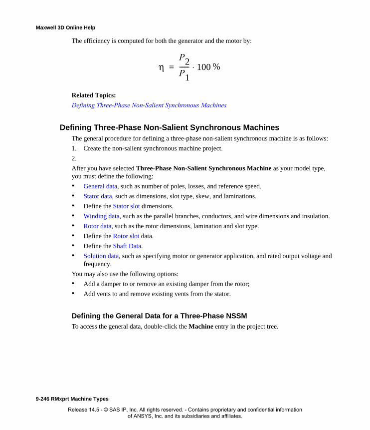
Maxwell 3D Online Help
The efficiency is computed for both the generator and the motor by:
Related Topics:
Defining Three-Phase Non-Salient Synchronous Machines
Defining Three-Phase Non-Salient Synchronous MachinesThe general procedure for defining a three-phase non-salient synchronous machine is as follows:
1. Create the non-salient synchronous machine project.
2.
After you have selected Three-Phase Non-Salient Synchronous Machine as your model type, you must define the following:
• General data, such as number of poles, losses, and reference speed.
• Stator data, such as dimensions, slot type, skew, and laminations.
• Define the Stator slot dimensions.
• Winding data, such as the parallel branches, conductors, and wire dimensions and insulation.
• Rotor data, such as the rotor dimensions, lamination and slot type.
• Define the Rotor slot data.
• Define the Shaft Data.
• Solution data, such as specifying motor or generator application, and rated output voltage and frequency.
You may also use the following options:
• Add a damper to or remove an existing damper from the rotor;
• Add vents to and remove existing vents from the stator.
Defining the General Data for a Three-Phase NSSM
To access the general data, double-click the Machine entry in the project tree.
ηP2P1------ 100⋅= %
9-246 RMxprt Machine Types
Release 14.5 - © SAS IP, Inc. All rights reserved. - Contains proprietary and confidential information of ANSYS, Inc. and its subsidiaries and affiliates.

Maxwell 3D Online Help
The Properties window for a three-phase non-salient synchronous machine contains the following fields to be entered:
Related Topics:
Defining the Stator for Three-Phase NSSM
Defining the Stator for Three-Phase NSSMThe stator is the outer lamination stack where the three-phase windings reside.
Double-click the icon Machine>Stator in the project tree to display the Properties dialog box.
The Properties window contains the following fields:
To define general stator data:
1. To open the Stator Data Properties window, double-click the Machine>Stator entry in the project tree on the desktop. (You can also enter values in the Properties section of the desktop without opening a separate window.)
2. Enter the Outer Diameter of the stator.
3. Enter the Inner Diameter of the stator.
4. Enter the length of the stator core in the Length field.
Machine Type The machine type you selected when inserting a new RMxprt design (Three Phase Non-Salient Synchronous Machine).
Number of Poles The number of poles the machine contains. This value is the total number of poles in the stator (or the number of pole pairs multiplied by two).
Frictional Loss The frictional energy loss (due to friction) measured at the reference speed.
Windage Loss The windage loss (due to air resistance) measured at the reference speed.
Reference Speed The given speed of reference.
Outer Diameter The outer diameter of the stator.
Inner Diameter The inner diameter of the stator.
Length The length of the stator core.
Stacking Factor The stacking factor of the stator core.
Steel Type The steel type of the stator core. Click the button to open the Select Definition window.
Number of Slots The number of slots the stator core contains.
Slot Type The type of slots in the stator core. Click the button to open the Select Slot Type window.
Lamination Sectors
The number of lamination sectors.
Pressboard Thickness
The magnetic press board thickness (enter 0 for a non-magnetic press board).
Skew Width The skew width measured in slot number.
RMxprt Machine Types 9-247
Release 14.5 - © SAS IP, Inc. All rights reserved. - Contains proprietary and confidential information of ANSYS, Inc. and its subsidiaries and affiliates.

Maxwell 3D Online Help
5. Enter the stacking factor for the stator core in the Stacking Factor field.
6. Select a Steel Type for the stator core:
a. Click the button for Steel Type.The Select Definition window appears.
b. Select a steel type from the list, or define a new steel type.
c. Click OK to close the Select Definition window and return to the Properties window.
7. Enter the Number of Slots in the stator.
8. Select the Slot Type:
a. Click the button for the Slot Type.The Select Slot Type window appears.
b. Select a slot type (available types include 1 through 6). Slot types 1 though 4 are filled with round wire. Slot types 5 and 6 are filled with rectangular wire. If Auto Design is enabled, the software designs an optimum slot geometry; in this case, you can input the tooth width dimension, and the software determines the slot width accordingly.
Optionally, check User Defined Slot if you wish to define the slot dimensions using the Slot Editor.
c. Click OK to close the Select Slot Type window and return to the Properties window.
9. Enter the number of sectors in the Lamination Sectors field.
10. Enter the thickness of the magnetic pressboard in the Pressboard Thickness field. Enter 0 for a non-magnetic pressboard.
11. Enter the skew width, measured in slot number, in the Skew Width field.
12. Click OK to close the Properties window.
Related Topics:
Defining Stator Slots for a Three-Phase NSSM
Defining Stator Slots for a Three-Phase NSSMTo define the slot dimensions:
1. To open the Stator Slot Data Properties window, double-click the Machine>Stator>Slot entry in the project tree on the desktop. (You can also enter values in the Properties section of the desktop without opening a separate window.)
2. Optionally, to automatically design the dimensions of slots Hs2, Bs1, and Bs2, select the Auto Design check box.
Note When you place the mouse cursor over the slot type, a schematic of the selected type appears, displaying the slot dimension variables.
9-248 RMxprt Machine Types
Release 14.5 - © SAS IP, Inc. All rights reserved. - Contains proprietary and confidential information of ANSYS, Inc. and its subsidiaries and affiliates.

Maxwell 3D Online Help
3. Enter the available slot dimensions.
4. Click OK to close the Properties window.
Related Topics:
Defining Stator Windings and Insulation for a Three-Phase NSSM
Defining Stator Windings and Insulation for a Three-Phase NSSMDouble-click the icon Machine>Stator>Winding in the project tree to display the Properties dia-log box, which has two tab sheets: Winding and End/Insulation.
Define Wires, Conductors and Windings of NSSM StatorIn the Winding tab, define the wire, conductor and winding of the stator.
Related Topics:
Hs0 Always available.
Hs2 Available only when Auto Design is cleared. When Auto Design is selected, this slot dimension is determined automatically.
Bs0 Always available.
Bs1 Available only when Auto Design is cleared. When Auto Design is selected, this slot dimension is determined automatically.
Bs2 Available only when Auto Design is cleared. When Auto Design is selected, this slot dimension is determined automatically.
Winding Layers The number of layers in the stator winding. Select the winding layers from the pull-down list (available choices 1 and 2).
Winding Type The type of the stator winding. Set the winding type to Editor to use the Winding Editor dialog to design the coil windings
Parallel Branches The number of parallel branches in one phase of the stator winding.
Conductors per Slot The total number of conductors in each stator slot. This value is the number of turns per coil multiplied by the number of layers. Enter 0 to have RMxprt auto-design this value.
Coil Pitch The coil pitch measured in number of slots. The coil pitch is the number of slots separating one winding. For example, if a coil starts in slot 1 and ends in slot 6, it has a coil pitch of 5.
Number of Strands The number of wires per conductor. Enter 0 to have RMxprt auto-design this value.
Wire Wrap The thickness of the double-sided wire wrap. Enter 0 to automatically obtain this value from the wire library.
Wire Size Wire size (0 for auto-design). You can assign wire size of round wires or rectangle wires. When the slot type you selected is 1 to 4, round wires are used. When the slot type you selected is 5 or 6, rectangle wires are used.
RMxprt Machine Types 9-249
Release 14.5 - © SAS IP, Inc. All rights reserved. - Contains proprietary and confidential information of ANSYS, Inc. and its subsidiaries and affiliates.
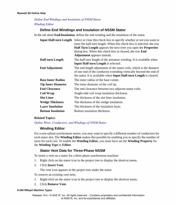
Maxwell 3D Online Help
Define End Windings and Insulation of NSSM Stator
Winding Editor
Define End Windings and Insulation of NSSM Stator
In the tab sheet End/Insulation, define the end winding and the insulation of the stator.
Related Topics:
Define Wires, Conductors, and Windings of NSSM Stator
Winding EditorFor a non-salient synchronous motor, you may want to specify a different number of conductors for each stator slot. The Winding Editor makes this possible by enabling you to specify the number of turns for each coil. To enable the Winding Editor, you must have set the Winding Property for the Winding Type to Editor.
Stator Vent Data for Three-Phase NSSM
To insert a vent on a stator for a three phase synchronous machine:
1. Right click on the stator icon in the project tree to display the shortcut menu.
2. Click Insert Vent.
The vent icon appears in the project tree under the stator.
To remove an existing vent item,
1. Right-click on the stator icon in the project tree to display the shortcut menu.
2. Click Remove Vent.
Input Half-turn Length Select or clear this check box to specify whether or not you want to enter the half-turn length. When this check box is selected, the row Half Turn Length appears the next time you open the Properties dialog box. When this check box is cleared, the row End Adjustment appears instead.
Half-turn Length The half-turn length of the armature winding. It is available when Input Half-turn Length is selected.
End Adjustment The end length adjustment of the stator coils, which is the distance of one end of the conductor extending vertically beyond the end of the stator. It is available when Input Half-turn Length is cleared.
Base Inner Radius The inner radius of the base corner.
Tip Inner Diameter The inner diameter of the coil tip.
End Clearance The end clearance between two adjacent stator coils.
Coil Wrap Single-side coil wrap insulation thickness.
Slot Liner The thickness of the slot liner insulation.
Wedge Thickness The thickness of the wedge insulation.
Layer Insulation The thickness of the insulation layer.
Bottom Insulation Bottom insulation thickness.
9-250 RMxprt Machine Types
Release 14.5 - © SAS IP, Inc. All rights reserved. - Contains proprietary and confidential information of ANSYS, Inc. and its subsidiaries and affiliates.

Maxwell 3D Online Help
This removes the vent item from the project tree.
To access the Vent properties for a vent, double click on a vent item. The Vent Properties window contains the following fields.
Define NSSM Rotor Data
Double-click the icon Machine>Rotor in the project tree to display the Properties dialog box, which has one tab sheet: Rotor. In the Rotor tab, define the rotor general data.
Define NSSM Rotor Slot
Double-click the icon Machine>Rotor>Slot in the project tree to display the Properties dialog box.
Vent Ducts The number of radial vent ducts.
Duct Width The width of the radial vent ducts.
Magnetic spacer width
Width of magnetic spacer which holds vent ducts. O for non-magnetic spacer.
Duct pitch. Center-to-Center distance between two adjacent Vent ducts
Outer Diameter The outer diameter of the rotor core.
Inner Diameter The inner diameter of the rotor core.
Length The length of the rotor core.
Stacking Factor Stacking factor of the rotor core.
Steel Type Select a steel type for the rotor core material.
Press Board Thickness Magnetic press board thickness, 0 for non-magnetic press board.
Indexing Slots Number of indexing slots of the rotor core used to determine slot pitch.
Real Slots Number of Slots of the rotor core.
Slot Type Slot type of the rotor core. There are six types of rotor slots.
RMxprt Machine Types 9-251
Release 14.5 - © SAS IP, Inc. All rights reserved. - Contains proprietary and confidential information of ANSYS, Inc. and its subsidiaries and affiliates.
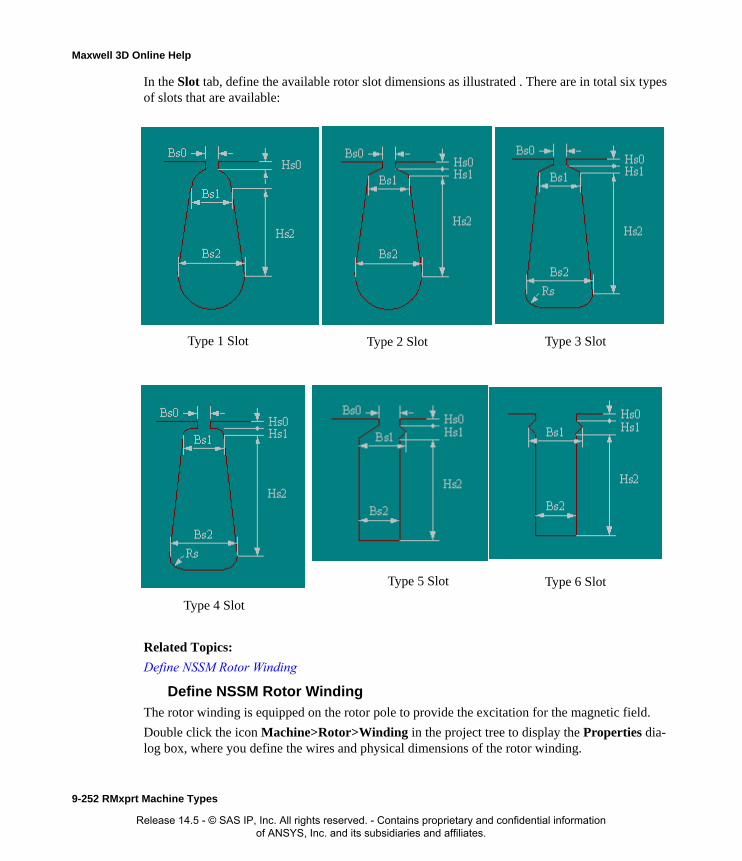
Maxwell 3D Online Help
In the Slot tab, define the available rotor slot dimensions as illustrated . There are in total six types of slots that are available:
Related Topics:
Define NSSM Rotor Winding
Define NSSM Rotor WindingThe rotor winding is equipped on the rotor pole to provide the excitation for the magnetic field.
Double click the icon Machine>Rotor>Winding in the project tree to display the Properties dia-log box, where you define the wires and physical dimensions of the rotor winding.
Type 1 Slot Type 2 Slot Type 3 Slot
Type 4 Slot
Type 6 SlotType 5 Slot
9-252 RMxprt Machine Types
Release 14.5 - © SAS IP, Inc. All rights reserved. - Contains proprietary and confidential information of ANSYS, Inc. and its subsidiaries and affiliates.

Maxwell 3D Online Help
In the Winding tab, the following are defined:.
In the End/Insulation tab the following are defined:
Related Topics:
Define NSSM Shaft Data
Rotor Vent Data for NSSMsBy option, you can add vents to a rotor in a three-phase NSSM.
To add a vents to the rotor:
1. Select the rotor icon in the project tree.
2. Right-click to display the pop-up menu and select Insert Vent.
Parallel Branches The number of parallel branches in the rotor winding.
Conductors per Slot The number of conductors per slot (0 for auto-design).
Number of Strands The number of wires per conductor (0 for auto-design).
Wire Wrap The thickness of the double-sided wire wrap (0 to automatically obtain this value from the wire library).
Wire Size Wire size (0 for auto-design). You can assign wire size of round wires or rectangle wires. When you select Round Wire for Winding Type, round wires are used ((refer to section 8.4.1 Assign Round Wire Sizes). Otherwise, rectangle wires are used (refer to section 8.4.2 Assign Rectangular Wire Size).
Input Half-turn Length Select or clear this check box to specify whether or not you want to enter the half-turn length. When this check box is selected, the row Half Turn Length appears the next time you open the Properties dialog box. When this check box is cleared, the row End Adjustment appears instead.
Half-turn Length The half-turn length of the armature winding. It is available when Input Half-turn Length is selected.
End Adjustment One-side end extended length.
Inner Fillet Radius Inner fillet radius at the span corner.
End Clearance End clearance between two adjacent coils.
Coil Wrap Insulation: single-side coil wrap thickness.
Slot Liner Insulation: slot liner thickness.
Wedge Thickness Insulation: wedge thickness.
Bottom Insulation Insulation: bottom insulation thickness.
Limited Cross Height The limited cross-section height for the winding design or arrangement, or Overall Height as shown in Figure 12.12 (0 for available maximum area).
Winding Fillet The size of the winding fillet.
RMxprt Machine Types 9-253
Release 14.5 - © SAS IP, Inc. All rights reserved. - Contains proprietary and confidential information of ANSYS, Inc. and its subsidiaries and affiliates.
Maxwell 3D Online Help
The vent icon appears in the project tree under the rotor.
To remove a vent to stator in a three-phase induction motor.
1. Select the rotor icon in the project tree.
2. Right-click to display the pop-up menu and select Remove Vent.
The vent icon disappears in the project tree under the stator.
The Vent data for the NSSM rotor includes the following fields.
Define NSSM Shaft DataTo define the shaft:
1. Click the icon Machine>Shaft in the project tree to display the Properties dialog box.
2. In the tab sheet Shaft, select or clear the check box Magnetic Shaft to specify whether or not the shaft is to be made of the magnetic material.
3. Click OK to close the Properties dialog box.
Analysis Setup for Three-Phase Non-Salient Synchronous Machines
Add Solution Setup for NSSMTo set up the solution data:
1. Right click the icon Analysis in the project tree, then click Add Solution Setup from the short-cut menu to display the dialog box Properties. There are two tab sheets.
2. On the General tab, define the solution setup data.
Surface Ducts Number of surface tangential vent ducts
Surface Duct Width Width of surface tangential vent ducts
Surface Duct Depth Depth of surface tangential vent ducts
Surface Duct Pitch Pitch of surface tangential vent ducts
Axial Ducts Number of axial vent ducts per pole
Axial Duct Width Width of axial vent ducts in main teeth
Axial Duct Depth Depth of axial vent ducts in main teeth
Operation Type Two options from the pull-down list: Generator and Motor.
Load Type Select a load type for the motor or generator from the pull-down list (refer to section 7.8 Assign Load Types).
Rated Apparent Power The output electric apparent power in kVA developed at the terminal for the generator, or
Rated Output Power: The output mechanical power in kW developed at the shaft for the motor.
9-254 RMxprt Machine Types
Release 14.5 - © SAS IP, Inc. All rights reserved. - Contains proprietary and confidential information of ANSYS, Inc. and its subsidiaries and affiliates.

Maxwell 3D Online Help
3. On the NSSM tab, define the connection data:
4. Click OK to close the pop-up dialog box
Validate NSSM Solution Setup1. Click RMxprt>Validation Check to display the information box Validation Check.
2. If any items do not pass validation, use the diagnostic information in the window to resolve any issues.
3. Click Close to close the information box Validation Check.
4. When the design has been validated, click RMxprt>Analyze All.
5. The analysis progress is shown in the Progress window and the analysis message is shown in the Message Manager.
Design Output for Non-Salient Synchronous MachinesWhen RMxprt has completed a solution, you can display and analyze the results in the following ways:
View Performance
To view the solutions:
Click RMxprt>Results>Solution Data to display the information box Solutions. It has three tab sheets.
In the tab sheet Performance, from the pull-down list Data, as shown in Figure 12.15, you have 13 different data tables for the line start permanent magnet motor, which can be used to define Output Variables for design optimization:
Rated Voltage The RMS line-to-line voltage.
Rated Speed The desired synchronous speed.
Operating Temperature The temperature at which the system functions, and select the units. The Operating Temperature will affect all winding resistances and therefore affect all ohmic losses.
Rated Power Factor The rated power factor. For generators, the rated output power is determined by the rated apparent power mutiplying the rated power factor.
Winding Connection Select Wye or Delta from the pull-down list.
Exciter Efficiency The percentage efficiency of the exciter used to supply the rotor winding with the DC current if it is mechanically connected to the shaft of the generator. The efficiency value ranges between 0% and 100% and will only affect the total efficiency result.
Input Exciting Current If the check box is selected, the companying edit box is enabled. You need to input the exciting current value and select the units if needed.
Exciting Current Exciting current for rated operation.
RMxprt Machine Types 9-255
Release 14.5 - © SAS IP, Inc. All rights reserved. - Contains proprietary and confidential information of ANSYS, Inc. and its subsidiaries and affiliates.

Maxwell 3D Online Help
• FEA input Data
• Field Winding
• Full-load Magnetic Variables
• Important Factors
• Material Consumption
• No-load Magnetic Variables
• Rated Operation
• Stator Slot
• Stator Winding
• Steady State Parameters per Unit
• Transient Data
• Transient Data per Unit
• Unsaturated Steady State Parameters
View Design Sheet
In the tab sheet Design Sheet, you have 12 sets of information, as follows:
• General Data
• Stator Data
• Stator Winding Data
• Rotor Data
• Field Winding Data
• Some Factors and Material Consumption
• Unsaturated Steady State Parameters
• No Load Magnetic Data
• Full Load Magnetic Data
• Full Load Electric Data
• Transient Parameters and Time Constants
• Transient FEA Input Data
Note To print the Design Sheet: Right click the Design Sheet, select Print from the shortcut menu, select the printer and other parameters from the dialog box Print, and click OK to print.
9-256 RMxprt Machine Types
Release 14.5 - © SAS IP, Inc. All rights reserved. - Contains proprietary and confidential information of ANSYS, Inc. and its subsidiaries and affiliates.
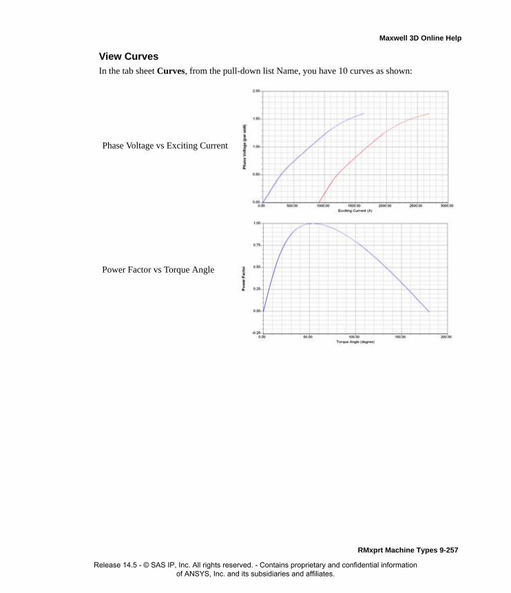
Maxwell 3D Online Help
View Curves
In the tab sheet Curves, from the pull-down list Name, you have 10 curves as shown:
Phase Voltage vs Exciting Current
Power Factor vs Torque Angle
RMxprt Machine Types 9-257
Release 14.5 - © SAS IP, Inc. All rights reserved. - Contains proprietary and confidential information of ANSYS, Inc. and its subsidiaries and affiliates.

Maxwell 3D Online Help
Armature Phase Current vs Torque Angle
Efficiency vs Torque Angle
Output Power vs Torque Angle
9-258 RMxprt Machine Types
Release 14.5 - © SAS IP, Inc. All rights reserved. - Contains proprietary and confidential information of ANSYS, Inc. and its subsidiaries and affiliates.

Maxwell 3D Online Help
Armature Current vs Exciting
Current
Cogging Torque in Two Teeth
Induced Coil Voltages at No Load
RMxprt Machine Types 9-259
Release 14.5 - © SAS IP, Inc. All rights reserved. - Contains proprietary and confidential information of ANSYS, Inc. and its subsidiaries and affiliates.
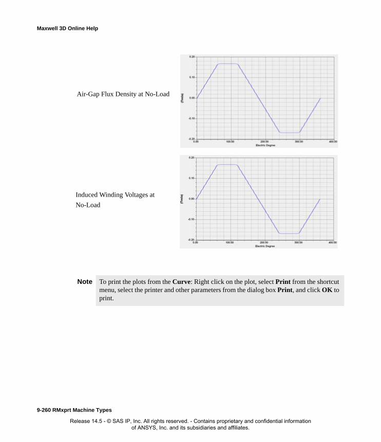
Maxwell 3D Online Help
Note To print the plots from the Curve: Right click on the plot, select Print from the shortcut menu, select the printer and other parameters from the dialog box Print, and click OK to print.
Air-Gap Flux Density at No-Load
Induced Winding Voltages at
No-Load
9-260 RMxprt Machine Types
Release 14.5 - © SAS IP, Inc. All rights reserved. - Contains proprietary and confidential information of ANSYS, Inc. and its subsidiaries and affiliates.

Maxwell 3D Online Help
Create Reports
1. Click RMxprt>Results>Create RMxprt Report>Rectangular Plot.
The dialog box Report appears as shown:
2. Under the tab sheet Trace, there are Variables, Output Variables, Current, Misc, Percent-age, and Power under the Category column. Select one from the Category column, select the traces that belong to it from the Quantity column, and click the button Add Trace to add them one by one. Finally click the button New report to create the plot. You can always add addi-tional curves to the same plot by repeating the process.
3. Double click the icon Results>XY Plot1 to display the graph with multiple traces in a new window.
Transient FEA of the Non-Salient Synchronous MachinesIf you expect to continue the transient or electromagnetic-field FEA with Maxwell2D, you can cre-ate Maxwell2D design directly from RMxprt, or export Maxwell2D project based on the .sm2 geometry file and then import the .sm2 file to a Maxwell2D design. For transient FEA, RMxprt can create a Maxwell2D design with all setups completed.
Note To print the plots from the Curves: Right click on the plot, select Print from the shortcut menu, select the printer and other parameters from the dialog box Print, and click OK to print.
To get a screen shot of from the Curves: Right click ont the plot, select Copy Image, then paste to a destination file.
RMxprt Machine Types 9-261
Release 14.5 - © SAS IP, Inc. All rights reserved. - Contains proprietary and confidential information of ANSYS, Inc. and its subsidiaries and affiliates.

Maxwell 3D Online Help
Create Maxwell 2D Design
Click the command RMxprt>Analysis Setup>Create Maxwell Design… in RMxprt to create a Maxwell2D design with Auto setup checked (refer to subsection 5.2.1 Create Maxwell 2D Design). A Maxwell2D design called Maxwell2DDesign1 is created with the displayed geometry as shown below. All setups are automatically completed by RMxprt.
Review Maxwell2D Design Setups
This section reviews all setups automatically completed by RMxprt. For detailed setup process, please refer to APPENDIX Setup Maxwell 2D Designs.
Solution Type Setup
Click Maxwell 2D>Solution Type… in Maxwell2D, you can review that the Solution Type is set as Magnetic Transient.
Model Setup1. Model Depth
Click Maxwell 2D>Design Setting… in Maxwell2D and click Set Model Depth… tab to review the Model Depth: 3590 mm.
2. Motion Type
Double click on Maxwell2DDesign1>Model>MotionSetup1 in the Project Manager window. In the Type tab you can review the Motion Type being set as Rotation, and the Moving Vec-tor as Positive Global: Z.
9-262 RMxprt Machine Types
Release 14.5 - © SAS IP, Inc. All rights reserved. - Contains proprietary and confidential information of ANSYS, Inc. and its subsidiaries and affiliates.

Maxwell 3D Online Help
3. Initial Position
In the Data tab of the Motion Setup panel you can review the Initial Position being set as 100 deg with Rotate Limit unchecked. The rotor initial position is set to such a position that the initial flux linkage of the phase-A winding is at its negative maximum value.
4. Mechanical Load
In the Mechanical tab of the Motion Setup panel you can review the Angular Velocity being set as 3000 rpm with Consider Mechanical Transient unchecked.
5. Symmetry Multiplier
Right click on Maxwell2DDesign1>Model in the Project Manager window, and select Set Geometry Multiplier in the pop-up panel, you can review that the Symmetry Multiplier is set as 2.
Boundary Setup
1. Vector Potential Boundary
Double click on Maxwell2DDesign1>Boundaries>VectorPotential1 in the Project Manager window, you can review that the highlighted outer half circle in the geometry is set as the Vec-tor Potential Boundary, and its value is set as 0.
2. Master Boundary
Click on Maxwell2DDesign1>Boundaries>Master1 in the Project Manager window, you can review that the highlighted arrowhead line from left to right in the geometry is set as the Mas-ter Boundary.
3. Slave Boundary
Double click on Maxwell2DDesign1>Boundaries>Slave1 in the Project Manager window, you can review that the highlighted arrowhead line from right to left in the geometry is set as the Slave Boundary, and the relation of the slave boundary to the master boundary is set as Bs = -Bm. This is because the geometry includes only 1 magnetic pole of the machine.
RMxprt Machine Types 9-263
Release 14.5 - © SAS IP, Inc. All rights reserved. - Contains proprietary and confidential information of ANSYS, Inc. and its subsidiaries and affiliates.
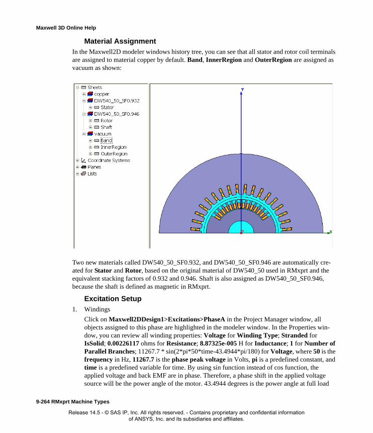
Maxwell 3D Online Help
Material Assignment
In the Maxwell2D modeler windows history tree, you can see that all stator and rotor coil terminals are assigned to material copper by default. Band, InnerRegion and OuterRegion are assigned as vacuum as shown:
Two new materials called DW540_50_SF0.932, and DW540_50_SF0.946 are automatically cre-ated for Stator and Rotor, based on the original material of DW540_50 used in RMxprt and the equivalent stacking factors of 0.932 and 0.946. Shaft is also assigned as DW540_50_SF0.946, because the shaft is defined as magnetic in RMxprt.
Excitation Setup
1. Windings
Click on Maxwell2DDesign1>Excitations>PhaseA in the Project Manager window, all objects assigned to this phase are highlighted in the modeler window. In the Properties win-dow, you can review all winding properties: Voltage for Winding Type; Stranded for IsSolid; 0.00226117 ohms for Resistance; 8.87325e-005 H for Inductance; 1 for Number of Parallel Branches; 11267.7 * sin(2*pi*50*time-43.4944*pi/180) for Voltage, where 50 is the frequency in Hz, 11267.7 is the phase peak voltage in Volts, pi is a predefined constant, and time is a predefined variable for time. By using sin function instead of cos function, the applied voltage and back EMF are in phase. Therefore, a phase shift in the applied voltage source will be the power angle of the motor. 43.4944 degrees is the power angle at full load
9-264 RMxprt Machine Types
Release 14.5 - © SAS IP, Inc. All rights reserved. - Contains proprietary and confidential information of ANSYS, Inc. and its subsidiaries and affiliates.

Maxwell 3D Online Help
operation. The values for resistance, inductance and number of parallel branches are obtained from the TRANSIENT FEA INPUT DATA section in RMxprt design sheet.
Clicking on PhaseB, PhaseC, or Field, you can review all objects assigned to this winding in the modeler window, and winding properties in the Properties window.
2. Coil Terminals
A winding consists of several coil terminals, and two coil terminals represent a coil in a com-plete 2D model. Since we are working with only one-half of the motor structure, one coil ter-minal can represent one complete coil with master/slave boundary conditions provided. A coil terminal has properties of Number of Conductors and Polarity Type. Number of Conduc-tors is the number of turns per coil, and it is equal to the Number of Turns given in RMxprt divided by number of coils per phase. Polarity Type defines the direction of the current in the coil; it can be either positive or negative. Expand a winding and click on a coil terminal, you can review the object corresponding to this coil terminal in the modeler window and all coil terminal properties in the Properties window. In this example, Number of Conductors of A, B, and C coil terminals is assigned as 1, and it is 12 for the Field windings. Click on PhaseB,
RMxprt Machine Types 9-265
Release 14.5 - © SAS IP, Inc. All rights reserved. - Contains proprietary and confidential information of ANSYS, Inc. and its subsidiaries and affiliates.
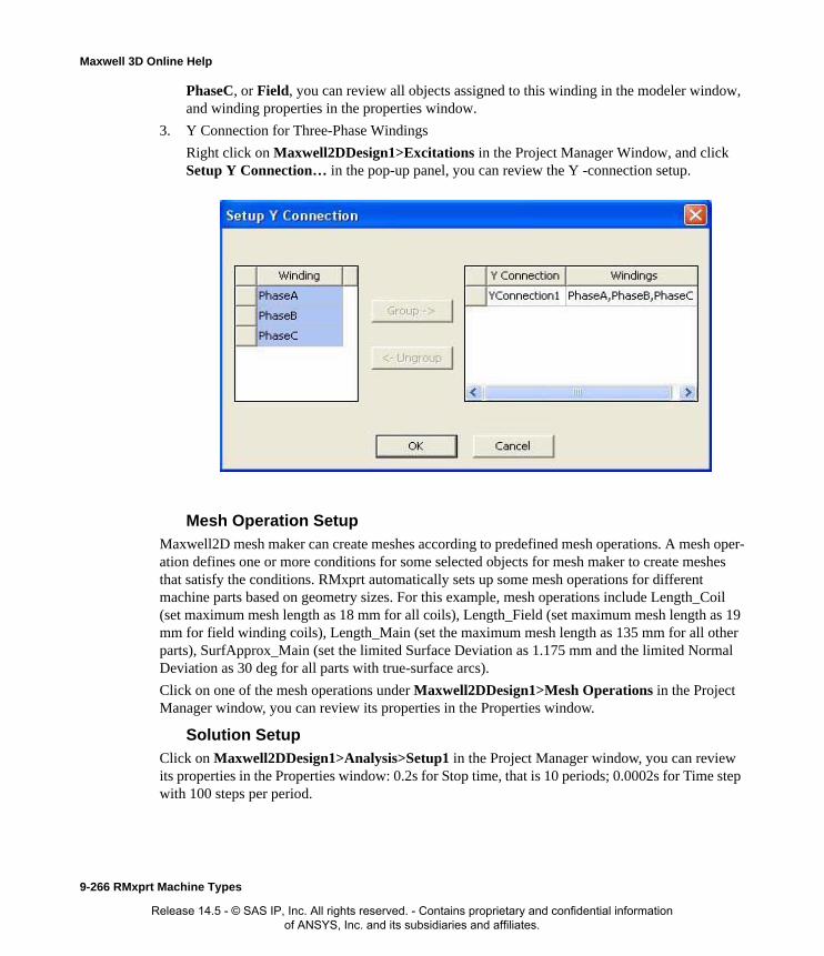
Maxwell 3D Online Help
PhaseC, or Field, you can review all objects assigned to this winding in the modeler window, and winding properties in the properties window.
3. Y Connection for Three-Phase Windings
Right click on Maxwell2DDesign1>Excitations in the Project Manager Window, and click Setup Y Connection… in the pop-up panel, you can review the Y -connection setup.
Mesh Operation Setup
Maxwell2D mesh maker can create meshes according to predefined mesh operations. A mesh oper-ation defines one or more conditions for some selected objects for mesh maker to create meshes that satisfy the conditions. RMxprt automatically sets up some mesh operations for different machine parts based on geometry sizes. For this example, mesh operations include Length_Coil (set maximum mesh length as 18 mm for all coils), Length_Field (set maximum mesh length as 19 mm for field winding coils), Length_Main (set the maximum mesh length as 135 mm for all other parts), SurfApprox_Main (set the limited Surface Deviation as 1.175 mm and the limited Normal Deviation as 30 deg for all parts with true-surface arcs).
Click on one of the mesh operations under Maxwell2DDesign1>Mesh Operations in the Project Manager window, you can review its properties in the Properties window.
Solution Setup
Click on Maxwell2DDesign1>Analysis>Setup1 in the Project Manager window, you can review its properties in the Properties window: 0.2s for Stop time, that is 10 periods; 0.0002s for Time step with 100 steps per period.
9-266 RMxprt Machine Types
Release 14.5 - © SAS IP, Inc. All rights reserved. - Contains proprietary and confidential information of ANSYS, Inc. and its subsidiaries and affiliates.

Maxwell 3D Online Help
Analyze Maxwell 2D Design
Before analyzing the Maxwell2D design, you may want to Apply Mesh Operations and Plot Mesh . You may also want to create several Quick Reports to display results.
To analyze the Maxwell2D design: right click on Maxwell2DDesign1>Analysis>Setup1 in the project tree, and click Analyze. While the design is being analyzed, you can update one or all result reports and view the reports.
To update all reports: right click on Maxwell2DDesign1>Results in the project tree, and select Update All Reports.
To update one report: right click on the report under Maxwell2DDesign1>Results in the project tree, and select Update Report.
To view all traces of a report: when you double click on the report under Maxwell2DDesign1>Results in the project tree, the Modeler window changes to the Results win-dow, and all traces (a curve in a report is a trace) of the selected reports are displayed in the Results window.
To view a trace of a report: when you click on a trace of a report under Maxwell2DDesign1>Results in the project tree, the selected trace is highlighted in the Results window.
To cancel the simulation: right click on the progress bar in the progress window, and pick up Abort in the pop-up panel.
To stop the simulation so that you can continue the simulation later: right click on the progress bar in the progress window, and pick up Clean Stop in the pop-up panel.
For this example, the simulated three-phase currents and the electro-magnetic torque are shown in Figure 12.24 and 12.25, respectively.
Right click on the Winding Quick Report in the Results window, and pick up Marker>Add X Marker in the pop-up panel, yellow-shaded boxes are added in the report to indicate X and all Y
RMxprt Machine Types 9-267
Release 14.5 - © SAS IP, Inc. All rights reserved. - Contains proprietary and confidential information of ANSYS, Inc. and its subsidiaries and affiliates.

Maxwell 3D Online Help
values. Click on the X box (or the vertical line), and drag it to some place where you see the steady-state peak value of a phase current as shown:
0. 00 50 .00 100 .0 0 15 0.0 0 2 00 .00T im e [m s ]
- 30 .00
- 20 .00
- 10 .00
0 .00
10 .00
20 .00
30 .00
Y1
[A]
A n s o ft C o rp o ra t io n M a xwe ll2 D De s ig n 1W ind ing Q u ic k R e p o rt
- 9.1 100- 7.2 366
13 .77 17
M X 1: 1 50 .86 07
C u rve In foC u rr en t (P h as e A )
S e tu p 1 : T r an s i e ntC u rr en t (P h as e B )
S e tu p 1 : T r an s i e ntC u rr en t (P h as e C )
S e tu p 1 : T r an s i e nt
9-268 RMxprt Machine Types
Release 14.5 - © SAS IP, Inc. All rights reserved. - Contains proprietary and confidential information of ANSYS, Inc. and its subsidiaries and affiliates.

Maxwell 3D Online Help
Add X makers in Torque Quick Report to indicate the steady-state maximum and minimum values of torque as shown below. The average torque can be approximately obtained from the maximum and minimum values as Tav = (Tmax + Tmin) / 2 = (10.63 + 7.33) / 2 = 8.98 Nm.
0.00 50.00 100.00 150.00 200.00Time [ms]
-20.00
-15.00
-10.00
-5.00
0.00
5.00
10.00
15.00
20.00
25.00
Mov
ing1
.Tor
que
[New
tonM
eter
]Ansoft Corporation Maxwell2DDesign1Torque
10.6253
7.3317
MX1: 127.3865MX2: 111.4241
Curve Info
RMxprt Machine Types 9-269
Release 14.5 - © SAS IP, Inc. All rights reserved. - Contains proprietary and confidential information of ANSYS, Inc. and its subsidiaries and affiliates.

Maxwell 3D Online Help
Generic Rotating MachinesAfter you have selected Generic Rotating Machine as your model type, the following machine data must be defined to configure the machine:
• General data, such as the source type (AC or DC), structure (inner or outer rotor), and rotor and stator types.
• Stator and rotor data, such as numbers of poles and slots, and circuit and slot types.
• Stator and rotor core data, such as dimensions, composition, lamination, and other physical characteristics.
• Stator and rotor slot design dimensions.
• Stator and rotor pole data, such as magnet type, length, and thickness.
• Stator and rotor winding data, such as winding type, number of layers and branches, conductor and coil data, and wire and insulation specifications.
• Shaft data.
• Solution data.
Optionally you can insert or remove the following for a Generic Rotating Machine.
• Vent data, added under a stator or rotor.
• Circuit data, added under a stator or rotor for DC source type machines.
• Brush data, added under an Axial AC rotor structure.
Analysis Approach for Generic Rotating MachinesGeneric Rotating Machines can be configured to operate as any of the following types:
• Generator
9-270 RMxprt Machine Types
Release 14.5 - © SAS IP, Inc. All rights reserved. - Contains proprietary and confidential information of ANSYS, Inc. and its subsidiaries and affiliates.

Maxwell 3D Online Help
Generic Rotating Machine Operating as a Generator
Doubly-fed induction generators (DFIGs) are widely used in wind power systems. A DFIG works as a component of a wind power system, as shown below, where the wind turbine transforms wind energy into mechanical energy, and the DFIG transforms mechanical energy into electrical energy.
For a DFIG, both the stator and the rotor are equipped with poly-phase AC windings. The stator and rotor windings may, or may not, have the same number of phases, but they must have the same number of poles p. In order to produce terminal voltages with desired frequency f in the stator winding, the rotor winding must be excited by balanced poly-phase currents with the slip frequency sf via an AC-DC-AC convert. Slip s is defined as:
where n is the rotor speed, and n0 is the synchronous speed as given below:
When the rotor speed is lower than the synchronous speed, the rotor currents have the same phase sequence as the stator currents, and the rotor winding gets power from the converter. However, when the rotor speed is higher than the synchronous speed, the phase sequence of the rotor currents is different from that of the stator currents, and the rotor winding outputs power to the converter.
For a given wind turbine, the power coefficient (the ratio of turbine power to the wind power), is a function of the tip speed ratio (the ratio of the blade tip speed to the wind speed). In order to track the maximum power point, the tip speed ratio must keep constant - at its optimal value. The input mechanical power with Maximum Power Point Tracking (MPPT) must satisfy:
s 1 n n0⁄–=
n0 60f p⁄=
Pmech Pm_ref ωm ωref⁄( )3⋅=
RMxprt Machine Types 9-271
Release 14.5 - © SAS IP, Inc. All rights reserved. - Contains proprietary and confidential information of ANSYS, Inc. and its subsidiaries and affiliates.
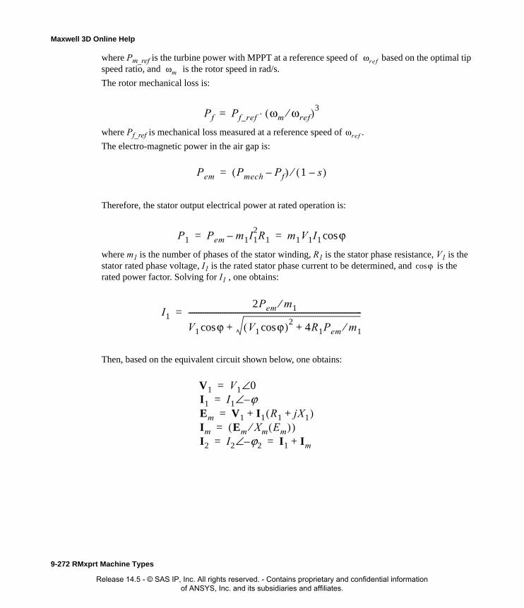
Maxwell 3D Online Help
where Pm_ref is the turbine power with MPPT at a reference speed of based on the optimal tip speed ratio, and is the rotor speed in rad/s.
The rotor mechanical loss is:
where Pf_ref is mechanical loss measured at a reference speed of .
The electro-magnetic power in the air gap is:
Therefore, the stator output electrical power at rated operation is:
where m1 is the number of phases of the stator winding, R1 is the stator phase resistance, V1 is the stator rated phase voltage, I1 is the rated stator phase current to be determined, and is the rated power factor. Solving for I1 , one obtains:
Then, based on the equivalent circuit shown below, one obtains:
ωrefωm
Pf Pf_ref ωm ωref⁄( )3⋅=
ωref
Pem Pmech Pf–( ) 1 s–( )⁄=
P1 Pem m1I12R1– m1V1I1 ϕcos= =
ϕcos
I12Pem m1⁄
V1 ϕ V1 ϕcos( )24R1Pem m1⁄++cos
--------------------------------------------------------------------------------------------=
V1 V1 0I1
∠I1 ϕ
Em
–∠V1 I1 R1 jX1+( )
Im
+Em Xm Em( )⁄( )
I2 I2 ϕ2–∠ I1 Im+
===
== =
9-272 RMxprt Machine Types
Release 14.5 - © SAS IP, Inc. All rights reserved. - Contains proprietary and confidential information of ANSYS, Inc. and its subsidiaries and affiliates.
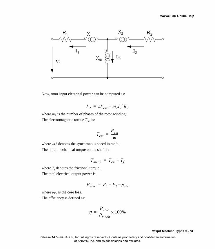
Maxwell 3D Online Help
Now, rotor input electrical power can be computed as:
where m2 is the number of phases of the rotor winding.
The electromagnetic torque Tem is:
where ? denotes the synchronous speed in rad/s.
The input mechanical torque on the shaft is:
where Tf denotes the frictional torque.
The total electrical output power is:
where pFe is the core loss.
The efficiency is defined as:
P2 sPem m2I22R2+=
Tem
Pem
ω---------=
ω
Tmech Tem Tf+=
Pelec P1 P2– pFe–=
ηPelec
Pmech-------------- 100%×=
RMxprt Machine Types 9-273
Release 14.5 - © SAS IP, Inc. All rights reserved. - Contains proprietary and confidential information of ANSYS, Inc. and its subsidiaries and affiliates.
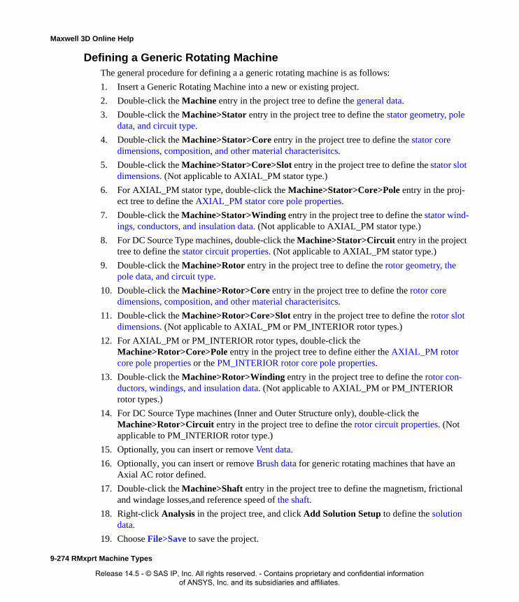
Maxwell 3D Online Help
Defining a Generic Rotating MachineThe general procedure for defining a a generic rotating machine is as follows:
1. Insert a Generic Rotating Machine into a new or existing project.
2. Double-click the Machine entry in the project tree to define the general data.
3. Double-click the Machine>Stator entry in the project tree to define the stator geometry, pole data, and circuit type.
4. Double-click the Machine>Stator>Core entry in the project tree to define the stator core dimensions, composition, and other material characterisitcs.
5. Double-click the Machine>Stator>Core>Slot entry in the project tree to define the stator slot dimensions. (Not applicable to AXIAL_PM stator type.)
6. For AXIAL_PM stator type, double-click the Machine>Stator>Core>Pole entry in the proj-ect tree to define the AXIAL_PM stator core pole properties.
7. Double-click the Machine>Stator>Winding entry in the project tree to define the stator wind-ings, conductors, and insulation data. (Not applicable to AXIAL_PM stator type.)
8. For DC Source Type machines, double-click the Machine>Stator>Circuit entry in the project tree to define the stator circuit properties. (Not applicable to AXIAL_PM stator type.)
9. Double-click the Machine>Rotor entry in the project tree to define the rotor geometry, the pole data, and circuit type.
10. Double-click the Machine>Rotor>Core entry in the project tree to define the rotor core dimensions, composition, and other material characterisitcs.
11. Double-click the Machine>Rotor>Core>Slot entry in the project tree to define the rotor slot dimensions. (Not applicable to AXIAL_PM or PM_INTERIOR rotor types.)
12. For AXIAL_PM or PM_INTERIOR rotor types, double-click the Machine>Rotor>Core>Pole entry in the project tree to define either the AXIAL_PM rotor core pole properties or the PM_INTERIOR rotor core pole properties.
13. Double-click the Machine>Rotor>Winding entry in the project tree to define the rotor con-ductors, windings, and insulation data. (Not applicable to AXIAL_PM or PM_INTERIOR rotor types.)
14. For DC Source Type machines (Inner and Outer Structure only), double-click the Machine>Rotor>Circuit entry in the project tree to define the rotor circuit properties. (Not applicable to PM_INTERIOR rotor type.)
15. Optionally, you can insert or remove Vent data.
16. Optionally, you can insert or remove Brush data for generic rotating machines that have an Axial AC rotor defined.
17. Double-click the Machine>Shaft entry in the project tree to define the magnetism, frictional and windage losses,and reference speed of the shaft.
18. Right-click Analysis in the project tree, and click Add Solution Setup to define the solution data.
19. Choose File>Save to save the project.
9-274 RMxprt Machine Types
Release 14.5 - © SAS IP, Inc. All rights reserved. - Contains proprietary and confidential information of ANSYS, Inc. and its subsidiaries and affiliates.

Maxwell 3D Online Help
20. Choose RMxprt>Analyze All to analyze the design.
Once analyzed, the model can be viewed in the Maxwell 2D Modeler, or it can be used to create a new Maxwell 2D project, and a new Maxwell 3D design.
Refer to the Generic Rotating Machine application note, on the technical support page of the ANSYS web site, for a specific example of a problem using a Generic Rotating Machine.
Defining the General Data for a Generic Rotating Machine
Use the Machine tab in the Properties dialog box (or Propertieswindow) to define the basic param-eters of the Generic Rotating Machine, such as the source type, structure, and rotor and stator types.
To define the general data:
1. To open the Properties dialog box, double-click the Machine entry in the project tree on the desktop. (You can also enter values in the Properties window of the desktop without opening the dialog box.)
2. Select the source type for the machine from the drop-down list in the Source Type Value field. The default value is AC.
3. Select the structure for the machine from the drop-down list in the Structure Value field. The default value is Inner Rotor.
a. Optionally, if the selected Structure is Axial-Flux Rotor, choose if either the rotor, sta-tor, or neither is to be Double-Sided. The default value is None.
b. Optionally, if the selected Structure is Axial-Flux Rotor, set the Air Gap Length.
4. Select the stator type for the machine from the drop-down list in the Stator Type Value field.
5. Select the rotor type for the machine from the drop-down list in the Rotor Type Value field.
6. Click OK to close the Properties dialog box.
General Data for Generic Rotating Machines
To access the general data, double-click the Machine entry in the project tree.
The General Data Properties window for a generic rotating machine contains the following fields:
Note When you place the cursor over an entry field, a brief description of that field appears in the status bar at the bottom of the RMxprt window.
Source Type The source to deliver electric power. (AC or DC) Default is AC.
Structure The type of rotor structure for the machine. (Inner Rotor, Outer Rotor, or Axial-Flux Rotor) Default is Inner Rotor.
Stator Type • The stator core type. (AXIAL_AC, AXIAL_PM, or SLOT_AC)
• If Structure type is Axial-Flux Rotor, then stator can be either AXIAL_AC or AXIAL_PM. Default is AXIAL_AC.
• If Structure type is Inner Rotor or Outer Rotor, stator type is SLOT_AC.
RMxprt Machine Types 9-275
Release 14.5 - © SAS IP, Inc. All rights reserved. - Contains proprietary and confidential information of ANSYS, Inc. and its subsidiaries and affiliates.

Maxwell 3D Online Help
Defining the Stator and Rotor Data for a Generic Rotating Machine
Use the Stator Properties and Rotor Properties dialog boxes to define the stator and rotor poles, slots, windings, and optional position control.
To define the general stator and rotor data:
1. To open the Stator or Rotor Properties dialog box, double-click the Machine>Stator (or Machine>Rotor) entry in the project tree on the desktop. (You can also enter values in the corresponding Properties window of the desktop without opening a separate dialog box.)
2. Enter the number of poles in the Number of Poles field.
3. Depending on the rotor or stator type being used, do one of the following:
a. If the rotor or stator type is AXIAL_AC or SLOT_AC, continue with step 4.
b. If the rotor or stator type is AXIAL_PM, there are no additional settings. Click OK to close the dialog.
c. If the rotor type is PM_INTERIOR, there are no additional settings. Click OK to close the dialog.
4. Enter the number of slots in the Number of Slots field.
5. Select a circuit type for the stator (or rotor):
a. Click the button for Circuit Type.
The Circuit Type dialog box appears.
b. Click a button to specify the desired circuit type.
c. Click OK to close the Circuit Type dialog box and return to the Properties dialog box.
6. Select a Slot Type:
a. Click the Slot Type button.
The Select Slot Type dialog box appears.
Rotor Type • The rotor core type. (AXIAL_AC, AXIAL_PM, SLOT_AC, or PM_INTERIOR)
• If Structure type is Outer Rotor, then rotor type is SLOT_AC.
• If Structure type is Axial-Flux Rotor, then rotor type can be either AXIAL_AC or AXIAL_PM.
• If Structure type is Inner Rotor, then rotor type can be either SLOT_AC or PM_INTERIOR.
Double-Sided Present only if Structure type is Axial-Flux.
• Choose Rotor, Stator, or None.
• Default is None.
Air Gap Length Present only if Structure type is Axial-Flux.
• Set the air gap length. Default is 0.
9-276 RMxprt Machine Types
Release 14.5 - © SAS IP, Inc. All rights reserved. - Contains proprietary and confidential information of ANSYS, Inc. and its subsidiaries and affiliates.
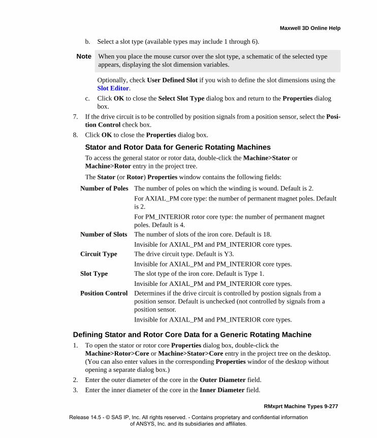
Maxwell 3D Online Help
b. Select a slot type (available types may include 1 through 6).
Optionally, check User Defined Slot if you wish to define the slot dimensions using the Slot Editor.
c. Click OK to close the Select Slot Type dialog box and return to the Properties dialog box.
7. If the drive circuit is to be controlled by position signals from a position sensor, select the Posi-tion Control check box.
8. Click OK to close the Properties dialog box.
Stator and Rotor Data for Generic Rotating Machines
To access the general stator or rotor data, double-click the Machine>Stator or Machine>Rotor entry in the project tree.
The Stator (or Rotor) Properties window contains the following fields:
Defining Stator and Rotor Core Data for a Generic Rotating Machine
1. To open the stator or rotor core Properties dialog box, double-click the Machine>Rotor>Core or Machine>Stator>Core entry in the project tree on the desktop. (You can also enter values in the corresponding Properties windor of the desktop without opening a separate dialog box.)
2. Enter the outer diameter of the core in the Outer Diameter field.
3. Enter the inner diameter of the core in the Inner Diameter field.
Note When you place the mouse cursor over the slot type, a schematic of the selected type appears, displaying the slot dimension variables.
Number of Poles The number of poles on which the winding is wound. Default is 2.
For AXIAL_PM core type: the number of permanent magnet poles. Default is 2.
For PM_INTERIOR rotor core type: the number of permanent magnet poles. Default is 4.
Number of Slots The number of slots of the iron core. Default is 18.
Invisible for AXIAL_PM and PM_INTERIOR core types.
Circuit Type The drive circuit type. Default is Y3.
Invisible for AXIAL_PM and PM_INTERIOR core types.
Slot Type The slot type of the iron core. Default is Type 1.
Invisible for AXIAL_PM and PM_INTERIOR core types.
Position Control Determines if the drive circuit is controlled by postion signals from a position sensor. Default is unchecked (not controlled by signals from a position sensor.
Invisible for AXIAL_PM and PM_INTERIOR core types.
RMxprt Machine Types 9-277
Release 14.5 - © SAS IP, Inc. All rights reserved. - Contains proprietary and confidential information of ANSYS, Inc. and its subsidiaries and affiliates.

Maxwell 3D Online Help
4. Enter the length of the core in the Length field.
5. Enter the stacking factor for the core in the Stacking Factor field. This value relates to the effective magnetic length of the core, and ranges from 0 to 1. It is defined as the total length minus the total insulation from the laminations, divided by the total length. A value of 1 indi-cates that the rotor is not laminated.
6. Select a Steel Type for the core:
a. Click the button for Steel Type.
The Select Definition dialog box appears.
b. Select a steel type from the list, or define a new steel type.
c. Click OK to close the Select Definition dialog box and return to the Properties dialog box.
7. Depending on the rotor or stator type being used, do one of the following:
a. If the Machine Rotor Type is PM_INTERIOR, continue with step 8.
b. If the Machine Rotor or Stator Type is SLOT_AC, AXIAL_AC, or AXIAL_PM, continue with step 9.
8. If the Machine Rotor Type is PM_INTERIOR, select a Pole Type for the core:
a. Click the button for Pole Type.
The Select Pole Type window appears.
b. Select the desired pole type (1 through 6). You can hover over the numbered buttons to view the pole type configuration in the window. The default type is 3.
c. Click OK to close the Select Pole Type window.
d. There are no additional settings for the PM_INTERIOR rotor type. Continue with step 11.
9. Enter the skew width (measured in degrees) in the Skew Width field.
10. If the Machine Structure type is either Inner Rotor or Outer Rotor and the Stator or Rotor Type is SLOT_AC:
a. Enter the thickness of the press boards in the Press Board Thickness field.
b. If the press board is made of magnetic material, check the Magnetic Press Board check-box.
c. Enter the number of lamination sectors in the Lamination Sectors field.
Note When Machine>Rotor>Core>Pole is selected in the Project Manager tree, the selected pole type diagram displays on the machine editor window Diagram tab. The Main tab also shows the pole drawing, which is dynamically updated as the pole properties are defined.
Note The Skew Width field is not available if the Machine Rotor Type is PM_INTERIOR.
Note The above settings are not available if the Machine Rotor Type is PM_INTERIOR.
9-278 RMxprt Machine Types
Release 14.5 - © SAS IP, Inc. All rights reserved. - Contains proprietary and confidential information of ANSYS, Inc. and its subsidiaries and affiliates.
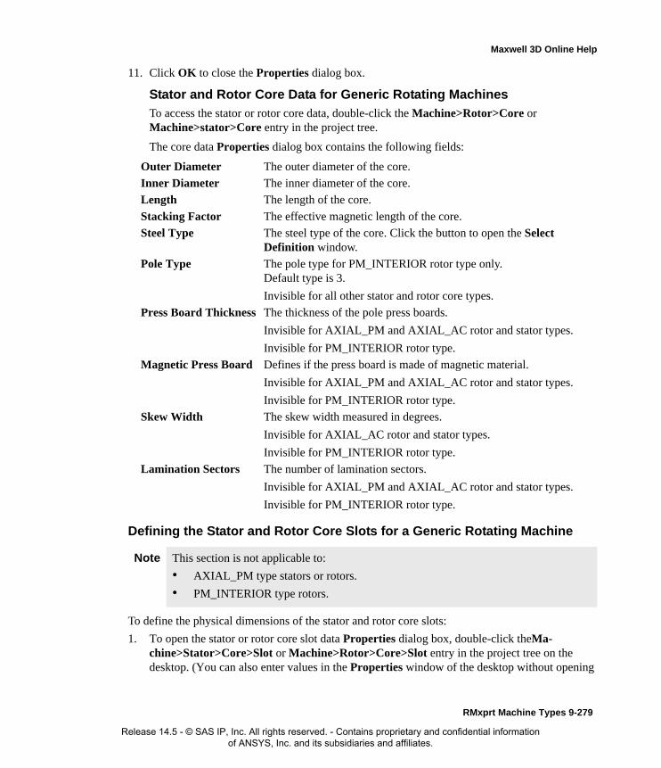
Maxwell 3D Online Help
11. Click OK to close the Properties dialog box.
Stator and Rotor Core Data for Generic Rotating Machines
To access the stator or rotor core data, double-click the Machine>Rotor>Core or Machine>stator>Core entry in the project tree.
The core data Properties dialog box contains the following fields:
Defining the Stator and Rotor Core Slots for a Generic Rotating Machine
To define the physical dimensions of the stator and rotor core slots:
1. To open the stator or rotor core slot data Properties dialog box, double-click theMa-chine>Stator>Core>Slot or Machine>Rotor>Core>Slot entry in the project tree on the desktop. (You can also enter values in the Properties window of the desktop without opening
Outer Diameter The outer diameter of the core.
Inner Diameter The inner diameter of the core.
Length The length of the core.
Stacking Factor The effective magnetic length of the core.
Steel Type The steel type of the core. Click the button to open the Select Definition window.
Pole Type The pole type for PM_INTERIOR rotor type only. Default type is 3.
Invisible for all other stator and rotor core types.
Press Board Thickness The thickness of the pole press boards.
Invisible for AXIAL_PM and AXIAL_AC rotor and stator types.
Invisible for PM_INTERIOR rotor type.
Magnetic Press Board Defines if the press board is made of magnetic material.
Invisible for AXIAL_PM and AXIAL_AC rotor and stator types.
Invisible for PM_INTERIOR rotor type.
Skew Width The skew width measured in degrees.
Invisible for AXIAL_AC rotor and stator types.
Invisible for PM_INTERIOR rotor type.
Lamination Sectors The number of lamination sectors.
Invisible for AXIAL_PM and AXIAL_AC rotor and stator types.
Invisible for PM_INTERIOR rotor type.
Note This section is not applicable to:
• AXIAL_PM type stators or rotors.
• PM_INTERIOR type rotors.
RMxprt Machine Types 9-279
Release 14.5 - © SAS IP, Inc. All rights reserved. - Contains proprietary and confidential information of ANSYS, Inc. and its subsidiaries and affiliates.

Maxwell 3D Online Help
a separate dialog box.)
2. Optionally, to automatically design the dimensions of slots Hs2, Bs1, and Bs2, select the Auto Design check box. Selecting Auto Design also disables the Parallel Tooth option.
3. Optionally, to automatically design Bs1 and Bs2 based on Tooth Width, select the Parallel Tooth check box. Selecting Parallel Tooth also enables the Tooth Width field.
4. Enter the available slot dimensions. The following dimensions may be listed, depending on the Slot Type selected and depending on whether or not Auto Design or Parallel Tooth is selected.:
5. Click OK to close the Properties window.
Core Slot Data for Generic Rotating MachinesTo access the core slot data, double-click either the Machine>Rotor>Core>Slot or the Machine>Rotor>Core>Slot entry in the project tree.
The core slot data Properties dialog box contains the following fields:
Hs0 Always available.
Hs1 Available only when the slot type is 2, 3, 4, 5, or 6.
Hs2 Available only when Auto Design is cleared. When Auto Design is selected, this slot dimension is determined automatically.
Bs0 Available only when the slot type is 1, 2, 3, 4, or 5.
Bs1 Available only when Auto Design is cleared. When Auto Design is selected, this slot dimension is determined automatically. When Parallel Tooth is selected, this slot dimension is determined based on the value entered in the Tooth Width field.
Bs2 Available only when Auto Design is cleared. When Auto Design is selected, this slot dimension is determined automatically. When Parallel Tooth is selected, this slot dimension is determined based on the value entered in the Tooth Width field.
Rs Available only when the slot type is 3 or 4.
Auto Design Select or clear this to enable or disable auto-design of slots Hs2, Bs1, and Bs2. When this check box is selected, only Hs0 , Hs1, Bs0 and Rs are present.
Parallel Tooth Select this to design Bs1 and Bs2 based on the tooth width. When this check box is selected, the Bs1 and Bs2 fields are removed, and the Tooth Width field is added.
Tooth Width The tooth width for the parallel tooth, on which Bs1 and Bs2 are designed.
Hs0 A slot dimension (see the diagram shown in the modeling window when Machine>Stator (or Rotor)>Core>Slot is selected).
Hs1 A slot dimension (see the diagram shown in the modeling window when Machine>Stator (or Rotor)>Core>Slot is selected).
Hs2 A slot dimension (see the diagram shown in the modeling window when Machine>Stator (or Rotor)>Core>Slot is selected).
9-280 RMxprt Machine Types
Release 14.5 - © SAS IP, Inc. All rights reserved. - Contains proprietary and confidential information of ANSYS, Inc. and its subsidiaries and affiliates.

Maxwell 3D Online Help
Defining AXIAL_PM Type Stator and Rotor Core Poles for a Generic Rotating Machine
To define the properties of AXIAL_PM type stator and rotor core poles:
1. To open the stator or rotor core pole data Properties dialog box, double-click theMa-chine>Stator>Core>Pole or Machine>Rotor>Core>Pole entry in the project tree on the desktop. (You can also enter values in the Properties window of the desktop without opening
Bs0 A slot dimension (see the diagram shown in the modeling window when Machine>Stator (or Rotor)>Core>Slot is selected).
Bs1 A slot dimension (see the diagram shown in the modeling window when Machine>Stator (or Rotor)>Core>Slot is selected).
Bs2 A slot dimension (see the diagram shown in the modeling window when Machine>Stator (or Rotor)>Core>Slot is selected).
Rs A slot dimension (see the diagram shown in the modeling window when Machine>Stator (or Rotor)>Core>Slot is selected).
Rs A slot dimension. (see the diagram shown in the modeling window when Machine>Stator (or Rotor)>Core>Slot is selected). Rs is added when the slot type is 3 or 4.
Note This section is applicable only to core poles for AXIAL_PM type stators or rotors.
To define core poles for PM_INTERIOR type rotors, refer to Defining PM_INTERIOR Type Rotor Core Poles for a Generic Rotating Machine.
RMxprt Machine Types 9-281
Release 14.5 - © SAS IP, Inc. All rights reserved. - Contains proprietary and confidential information of ANSYS, Inc. and its subsidiaries and affiliates.
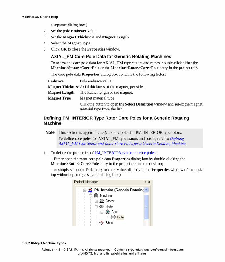
Maxwell 3D Online Help
a separate dialog box.)
2. Set the pole Embrace value.
3. Set the Magnet Thickness and Magnet Length.
4. Select the Magnet Type.
5. Click OK to close the Properties window.
AXIAL_PM Core Pole Data for Generic Rotating Machines
To access the core pole data for AXIAL_PM type stators and rotors, double-click either the Machine>Stator>Core>Pole or the Machine>Rotor>Core>Pole entry in the project tree.
The core pole data Properties dialog box contains the following fields:
Defining PM_INTERIOR Type Rotor Core Poles for a Generic Rotating Machine
1. To define the properties of PM_INTERIOR type rotor core poles:
– Either open the rotor core pole data Properties dialog box by double-clicking the Machine>Rotor>Core>Pole entry in the project tree on the desktop;
– or simply select the Pole entry to enter values directly in the Properties window of the desk-top without opening a separate dialog box.)
Embrace Pole embrace value.
Magnet Thickness Axial thickness of the magnet, per side.
Magnet Length The Radial length of the magnet.
Magnet Type Magnet material type.
Click the button to open the Select Definition window and select the magnet material type from the list.
Note This section is applicable only to core poles for PM_INTERIOR type rotors.
To define core poles for AXIAL_PM type stators and rotors, refer to Defining AXIAL_PM Type Stator and Rotor Core Poles for a Generic Rotating Machine.
9-282 RMxprt Machine Types
Release 14.5 - © SAS IP, Inc. All rights reserved. - Contains proprietary and confidential information of ANSYS, Inc. and its subsidiaries and affiliates.

Maxwell 3D Online Help
• If you wish to change the pole type, select the Machine>Rotor>Core entry in the project tree, then click the Pole Type button in its Properties window to open the Select Pole Type window.
• Select the desired pole type (1 through 6). You can hover over the numbered buttons to view the pole type configuration in the window. The default type is 3.
• Click OK to close the Select Pole Type window
2. Set the D1 diameter for magnet ducts.
3. Set the O1, O2, B1, Rib, and HRib magnet duct dimensions.
4. Set the number of duct Layers. Default value is 1.
5. Set the Layer Pitch value (pitch value between two layers).
6. Set the Magnet Thickness value.
7. Set the Magnet Width value (total width of all magnets per pole).
8. Select the Magnet Type by clicking the button to open the Select Definition window Materi-als tab and selecting the desired magnet material type. Use the Material Filter tab settings to filter for Magnet materials. Click OK to close the window.
9. Click OK to close the Properties window.
PM_INTERIOR Rotor Core Pole Data for Generic Rotating Machines
To access the core pole data for PM_INTERIOR type rotors, double-click the Machine>Rotor>Core>Pole entry in the project tree.
The core pole data Properties dialog box contains the following fields:
Note • The currently selected pole type diagram displays on the machine editor window Diagram tab. The Main tab also shows the pole drawing, which is dynamically updated as the pole properties are defined.
• Undo and Redo of property changes is supported.
Note • Dimension O1 is invisible for pole types 1 and 2.
• Dimension HRib is invisible for pole types 1, 2, and 6.
D1 Limited diameter for magnet ducts.
O1 Magnet duct dimension.
Invisible when pole type is 1 or 2.
O2 Magnet duct dimension.
B1 Magnet duct dimension.
Rib Magnet duct dimension.
HRib Magnet duct dimension.
Invisible when pole type is 1,2, or 6.
RMxprt Machine Types 9-283
Release 14.5 - © SAS IP, Inc. All rights reserved. - Contains proprietary and confidential information of ANSYS, Inc. and its subsidiaries and affiliates.

Maxwell 3D Online Help
PM_INTERIOR Rotor Core Pole TypesThe PM_INTERIOR rotor core type supports six pole types. You can choose the pole type by selecting the Machine>Rotor>Core entry in the project tree, then clicking the Pole Type but-ton in its Properties window to open the Select Pole Type window.
Layers Number of duct layers.
Layer Pitch Pitch between two duct layers.
Magnet Thickness Magnet thickness, or duct thickness.
Magnet Width Total width of all magnets per pole.
Magnet Type Magnet material type.
Click the button to open the Select Definition window and select the magnet material type from the list. Use the Material Filter tab settings to filter for Magnet materials.
9-284 RMxprt Machine Types
Release 14.5 - © SAS IP, Inc. All rights reserved. - Contains proprietary and confidential information of ANSYS, Inc. and its subsidiaries and affiliates.

Maxwell 3D Online Help
The six available pole types are shown below. Refer to Defining PM_INTERIOR Type Rotor Core Poles for a Generic Rotating Machine for details on defining the various pole properties.
Pole Type 1 Pole Type 2
Pole Type 3 Pole Type 4
RMxprt Machine Types 9-285
Release 14.5 - © SAS IP, Inc. All rights reserved. - Contains proprietary and confidential information of ANSYS, Inc. and its subsidiaries and affiliates.
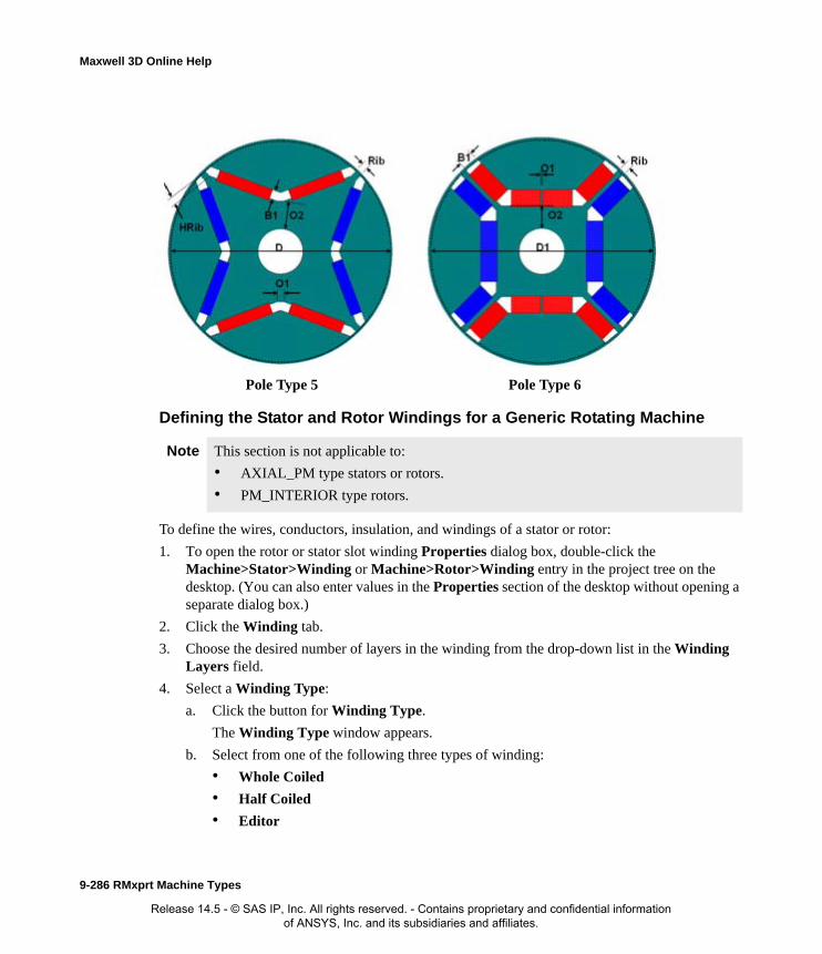
Maxwell 3D Online Help
Defining the Stator and Rotor Windings for a Generic Rotating Machine
To define the wires, conductors, insulation, and windings of a stator or rotor:
1. To open the rotor or stator slot winding Properties dialog box, double-click the Machine>Stator>Winding or Machine>Rotor>Winding entry in the project tree on the desktop. (You can also enter values in the Properties section of the desktop without opening a separate dialog box.)
2. Click the Winding tab.
3. Choose the desired number of layers in the winding from the drop-down list in the Winding Layers field.
4. Select a Winding Type:
a. Click the button for Winding Type.
The Winding Type window appears.
b. Select from one of the following three types of winding:
• Whole Coiled
• Half Coiled
• Editor
Pole Type 5 Pole Type 6
Note This section is not applicable to:
• AXIAL_PM type stators or rotors.
• PM_INTERIOR type rotors.
9-286 RMxprt Machine Types
Release 14.5 - © SAS IP, Inc. All rights reserved. - Contains proprietary and confidential information of ANSYS, Inc. and its subsidiaries and affiliates.

Maxwell 3D Online Help
When you place the mouse cursor over a winding button, an outline of the selected wind-ing appears. The following table describes the six types of windings that are possible (three for one-layer and three for two-layer):
Type DescriptionWinding Editor
(one-layer)
A user-defined one-layer winding arrangement. You need to set up the winding arrangement for each slot in the Winding Editor.
Whole-Coiled
(one-layer)
A one-layer whole-coiled winding:
Half-Coiled
(one-layer)
A one-layer concentric half-coiled winding:
123Slot
123Slot
RMxprt Machine Types 9-287
Release 14.5 - © SAS IP, Inc. All rights reserved. - Contains proprietary and confidential information of ANSYS, Inc. and its subsidiaries and affiliates.
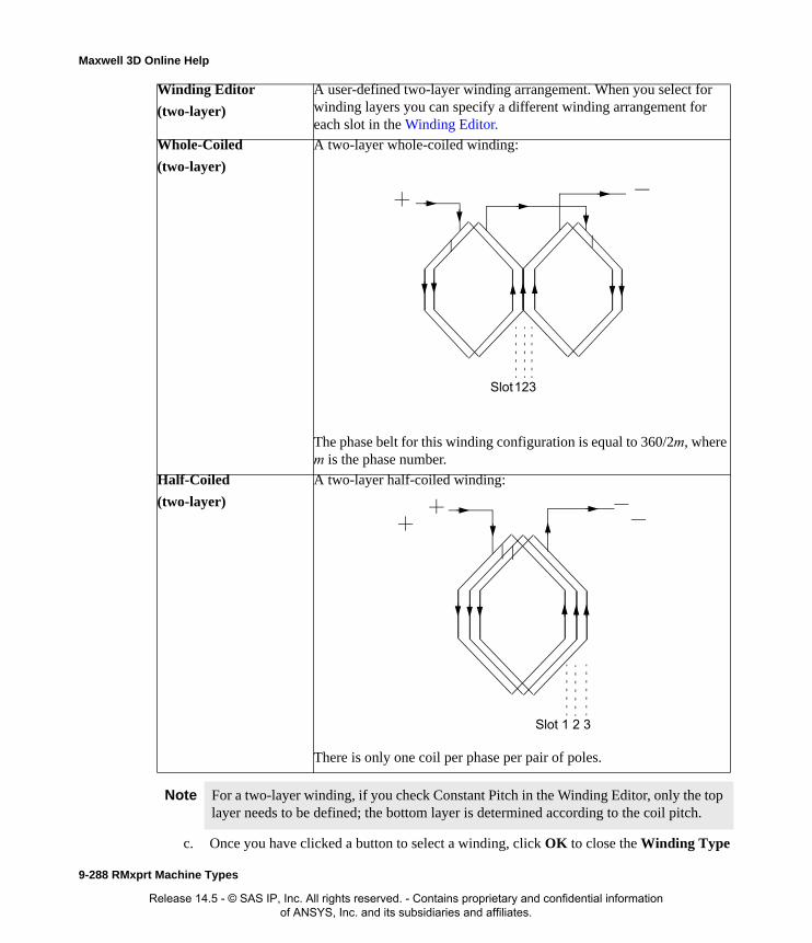
Maxwell 3D Online Help
c. Once you have clicked a button to select a winding, click OK to close the Winding Type
Winding Editor
(two-layer)
A user-defined two-layer winding arrangement. When you select for winding layers you can specify a different winding arrangement for each slot in the Winding Editor.
Whole-Coiled
(two-layer)
A two-layer whole-coiled winding:
The phase belt for this winding configuration is equal to 360/2m, where m is the phase number.
Half-Coiled
(two-layer)
A two-layer half-coiled winding:
There is only one coil per phase per pair of poles.
Note For a two-layer winding, if you check Constant Pitch in the Winding Editor, only the top layer needs to be defined; the bottom layer is determined according to the coil pitch.
123Slot
1 2 3Slot
9-288 RMxprt Machine Types
Release 14.5 - © SAS IP, Inc. All rights reserved. - Contains proprietary and confidential information of ANSYS, Inc. and its subsidiaries and affiliates.

Maxwell 3D Online Help
dialog box and return to the Properties window.
5. Enter the number of parallel branches in one phase of the winding in the Parallel Branches field.
6. Enter the total number of conductors in each slot in the Conductors per Slot field. This value is the number of turns per coil multiplied by the number of layers. Enter 0 to have RMxprt auto-design this value.
7. Enter the coil pitch, measured in number of slots, in the Coil Pitch field. The coil pitch is the number of slots separating one winding. For example, if a coil starts in slot 1 and ends in slot 6, it has a coil pitch of 5.
This field is not displayed when the number of Winding Layers is 1.
8. Enter the number of wires per conductor in the Number of Strands field. Enter 0 to have RMxprt auto-design this value.
9. Enter the thickness of the double-sided wire wrap in the Wire Wrap field. Enter 0 to automat-ically obtain this value from the wire library.
10. Select the Wire Size:
a. Click the button for Wire Size.
The Wire Size dialog box appears.
b. Select a value from the Wire Diameter pull-down list.
c. Select a wire gauge from the Gauge pull-down menu. You can select from the following options:
<number> You can select a specific gauge number. When you select a gauge number, the Wire Diameter field is automatically updated.
Insulation
Conductor
y
Wire Wrap = 2*y
RMxprt Machine Types 9-289
Release 14.5 - © SAS IP, Inc. All rights reserved. - Contains proprietary and confidential information of ANSYS, Inc. and its subsidiaries and affiliates.

Maxwell 3D Online Help
The gauge number is based on AWG settings. You can create your own wire table using Machine>Wire, and then you can select this wire table using the Tools>Options>Machine Options command.
d. When you are done setting the wire size, click OK to close the Wire Size dialog box and return to the Properties dialog box.
11. Click the End/Insulation tab.
12. Select or clear the Input Half-turn Length check box.
13. Do one of the following:
• If you selected Input Half-turn Length, then enter the half-turn length of the armature winding in the Half Turn Length field.
• If you cleared Input Half-turn Length, then enter the end length adjustment of the stator/rotor coils in the End Extension field. The end extension is the distance one end of the conductor extends vertically beyond the end of the stator or rotor.
14. Enter the inner radius of the base corner in the Base Inner Radius field.
15. Enter the inner diameter of the coil tip in the Tip Inner Diameter field.
16. Enter the distance between two adjacent coils in the End Clearance field.
USER This option allows you to manually enter the Wire Diameter. This is useful when you want to enter a diameter that does not correspond to a particular wire gauge.
AUTO This option sets the Wire Diameter to zero, and RMxprt automatically calculates the optimal value. The diameter information is then written to the output file when you analyze the design.
MIXED This option allows you to define a conductor that is made of different size wires. For example, a single conductor may consist of 5 wires, 3 wires with a diameter of 0.21mm and 2 with a diameter of 0.13mm.
EndExtension
Stator/RotorCoil
End of Stator/Rotor
9-290 RMxprt Machine Types
Release 14.5 - © SAS IP, Inc. All rights reserved. - Contains proprietary and confidential information of ANSYS, Inc. and its subsidiaries and affiliates.

Maxwell 3D Online Help
17. Enter the thickness of the single-side coil wrap insulation in the Coil Wrap field.
This field is applicable and displayed only for slot types 5 and 6.
18. Enter the thickness of the slot liner insulation in the Slot Liner field.
19. Enter the thickness of the wedge insulation in the Wedge Thickness field.
20. Enter the thickness of the insulation layer in the Layer Insulation field.
This field is applicable and displayed only when the Winding Layers value is 2.
21. Enter the bottom insulation thickness in the Bottom Insulation field.
This field is applicable and displayed only for slot types 5 and 6.
22. Enter the limited slot fill factor for the wire design in the Limited Fill Factor field.
This field is applicable and displayed only for slot types 1, 2, 3, and 4.
23. Enter the span lenght correction factor to scale the end span length in the Correction Factor field.
24. Enter the top spare slot space for a dual-winding machine in the Top Spare Space field.
25. Enter the bottom spare slot space for a dual-winding machine in the Bottom Spare Space field.
26. Click OK to close the Properties dialog box.
Stator and Rotor Winding Data for Generic Rotating Machines
To access the core slot data, double-click either the Machine>Rotor>Core>Slot or the Machine>Rotor>Core>Slot entry in the project tree.
The winding data Properties dialog box contains the following fields:
Note This section is not applicable to:
• AXIAL_PM type stators or rotors.
• PM_INTERIOR type rotors.
Winding tab Winding Layers The number of winding layers. (The bottom layer is for another side slot if the core is double-sided.)
Select 1 or 2 in the pull-down list. Default value is 2.
Winding Layers is always 2 if the core is double-sided.
Winding Type The type of stator winding. Click the button to open the Winding Type window and choose from Whole-Coiled, Half-Coiled, and Editor.
Default value is Whole-Coiled.
Parallel Branches The number of parallel branches in the winding. Default value is 1.
RMxprt Machine Types 9-291
Release 14.5 - © SAS IP, Inc. All rights reserved. - Contains proprietary and confidential information of ANSYS, Inc. and its subsidiaries and affiliates.
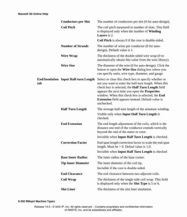
Maxwell 3D Online Help
Conductors per Slot The number of conductors per slot (0 for auto-design).
Coil Pitch The coil pitch measured in number of slots. This field is displayed only when the number of Winding Layers is 2.
Coil Pitch is always 0 if the core is double-sided.
Number of Strands The number of wires per conductor (0 for auto-design). Default value is 1.
Wire Wrap The thickness of the double-sided wire wrap (0 to automatically obtain this value from the wire library).
Wire Size The diameter of the wire (0 for auto-design). Click the button to open the Wire Size dialog box where you can specify units, wire type, diameter, and gauge.
End/Insulation tab
Input Half-turn Length Select or clear this check box to specify whether or not you want to enter the half-turn length. When this check box is selected, the Half Turn Length field appears the next time you open the Properties window. When this check box is selected, the End Extension field appears instead. Default value is unchecked.
Half Turn Length The average half-turn length of the armature winding.
Visible only when Input Half Turn Length is checked.
End Extension The end length adjustment of the coils, which is the distance one end of the conductor extends vertically beyond the end of the stator or rotor.
Invisible when Input Half Turn Length is checked.
Correction Factor End span length correction factor to scale the end span length. Must be > 0. Defaul value is 1.0.
Invisible when Input Half Turn Length is checked
Base Inner Radius The inner radius of the base corner.
Tip Inner Diameter The inner diameter of the coil tip.
Invisible if the core is double-sided.
End Clearance The end clearance between two adjacent coils.
Coil Wrap The thickness of the single-side coil wrap. This field is displayed only when the Slot Type is 5 or 6.
Slot Liner The thickness of the slot liner insulation.
9-292 RMxprt Machine Types
Release 14.5 - © SAS IP, Inc. All rights reserved. - Contains proprietary and confidential information of ANSYS, Inc. and its subsidiaries and affiliates.

Maxwell 3D Online Help
Winding Editor for a Generic Rotating MachineFor a generic rotating machine, you may want to specify a different number of conductors for each stator or rotor slot. The Winding Editor enables you to specify the number of turns for each coil. To enable the Winding Editor, you must have set the Winding Property for the Winding Type to Editor.
To specify the number of turns for each coil:
Wedge Thickness The thickness of the wedge insulation.
Layer Insulation The thickness of the insulation layer.
Invisible when number of winding layers is 1 or the core is double-sided.
Bottom Insulation Thickness of the bottom insulation. This field is displayed only when the Slot Type is 5 or 6.
Limited Fill Factor The limited slot fill factor for the wire design. This field is displayed only for Slot Types 1, 2, 3, or 4.
Top Spare Space The top spare slot space for a dual-winding machine. The value must be greater-than or equal-to 0 and less-than 1.
Bottom Spare Space The bottom spare slot space for a dual-winding machine. The value must be greater-than or equal-to 0.
Also, the sum of the Top Spare Space and Bottom Spare Space values must less-than 1.
Conductor Type Conductor material type of the Stator/Rotor Winding.
RMxprt Machine Types 9-293
Release 14.5 - © SAS IP, Inc. All rights reserved. - Contains proprietary and confidential information of ANSYS, Inc. and its subsidiaries and affiliates.

Maxwell 3D Online Help
1. Click Machine>Winding>Edit Layout.
The Winding Editor dialog box appears.
2. In the table in the upper left, set which Phase you want for each coil and which slot is the “In” and “Out” slot for the current in each coil.
3. If you are working on a quarter or half model, you may want to specify a multiplier by selecting a value from the Periodic Multiplier drop-down menu.
4. Select or deselect the Constant Turns or Constant Pitch check boxes, depending on whether you want to be able to change these setting in the table above. When these options are selected, you cannot change the turns or pitch.
5. When you are satisfied with the coil settings, click OK to close the Winding Editor dia-log box.
Defining Different Size Wires for a Generic Rotating Machine
Use the Gauge option if you have a conductor that is made up different size wires.
To define different size wires:
1. In the Wire Size window, select MIXED from the Gauge pull-down menu.
2. Select either Round or Rectangular as the Wire Type.
3. Enter the appropriate wire data in the table:
• For a round wire:
• Click Add to add the new wire datat.
• Enter the Diameter in the table.
• Enter a Number in the table to specify how many of the conductor’s wires have this diameter.
• For a rectangular wire:
• Click Add to add the new wire data.
• Enter the Width of the wire in the table. The width should be greater thatn the thickness.
• Enter the Thickness of the wire in the table.
• Enter the Fillet value in the table.
• Enter a Number in the table to specify how many of the conductor’s wires have this data.
4. Repeat step 3 for each size wire you want to add.
5. When you are finished defining the wires, click OK to close the Wire Size window.
Note For example, if one conductor is made up of 5 wires, and 3 of those wires have a diameter of 0.21mm, and the other 2 have a diameter of 0.13mm, then the mixed wire size table will have two lines. The first line will list Diameter = 0.21 and Number = 3. The second line will list Diameter = 0.13 and Number = 2. An equivalent wire diameter is displayed as Wire Size value in the Winding tab in the Properties window.
9-294 RMxprt Machine Types
Release 14.5 - © SAS IP, Inc. All rights reserved. - Contains proprietary and confidential information of ANSYS, Inc. and its subsidiaries and affiliates.

Maxwell 3D Online Help
Defining the Stator and Rotor Circuits for a Generic Rotating Machine
You can define stator and rotor Circuit parameters for generic rotating machines whose Source Type is DC.
To define the circuit parameters of a stator or rotor:
1. To define the circuit parameters click either the stator or rotor Circuit icon in the project tree. You can then edit the brush parameters directly in the Properties window. (You can also open the rotor or stator circuit Properties dialog box by double-clicking the Machine>Stator>Cir-cuit or Machine>Rotor>Circuit entry in the project tree on the desktop.)
2. Select the Control Type from the drop down menu. Choices are: DC, CCC, PWM, and HCC.
3. If the stator or rotor Position Control has been enabled, set the Lead Angle of Trigger value.
4. If the Control Type chosen is either DC or CCC, set the Trigger Pulse Width. The default value is 120.
5. Set the Transistor Drop (voltage drop of one transistor).
6. Set the Diode Drop.
7. If the Control Type is CCC, set the Maximum Current and Minimun Current values.
8. If the Control Type is PWM, set the Modulation Index and Carrier Frequency Times.
9. If the Control Type is HCC, set the Reference Amplitutde and Hysteresis Band.
Stator and Rotor Circuit Data for Generic Rotating MachinesTo access the stator or rotor circuit data, double-click either the Machine>Stator>Circuit or the Machine>Rotor>Circuit entry in the project tree.
The circuit data Properties dialog box contains the following fields:
Note This procedure is not applicable to:
• AXIAL_PM type stators or rotors.
• AXIAL_AC type rotors.
• PM_INTERIOR type rotors.
Control Type Control Type: DC, CCC (chopping current control ), PWM, HCC (hysteresis current control). Default is DC.
Lead Angle of Trigger Lead angle of trigger in electrical degrees.
Visible only when Position Control is enabled.
Trigger Pulse Width Trigger pulse width in electrical degrees.
Visible only when Control Type is DC or CCC. Default value is 120.
Transistor Drop Voltage drop of one transistor.
Diode Drop Voltage drop of one diode, or the total voltage for star-type circuits in the discharge loop.
RMxprt Machine Types 9-295
Release 14.5 - © SAS IP, Inc. All rights reserved. - Contains proprietary and confidential information of ANSYS, Inc. and its subsidiaries and affiliates.

Maxwell 3D Online Help
Defining the Axial AC Rotor Brush for a Generic Rotating Machine
Optionally, you can insert or remove brush data for generic rotating machines that have an Axial AC Rotor Structure. If you have inserted a brush, the icon appears under the core slot in the project tree.
To insert a brush:
1. Right-click on the rotor core icon to display the pop-up menu.
2. Click Insert Brush.
3. To edit the brush data, double-click the brush icon to open the brush properties dialog.
The brush data Properties dialog box contains the following fields:
To remove an existing brush:
1. Right click on the rotor icon to display the pop-up menu.
2. Click Remove Brush.
Maximum Current Maximum current for chopping current control.
Visible only when Control Type is CCC.
Minimum Current Minimum current for chopping current control.
Visible only when Control Type is CCC.
Modulation Index Modulation index (the ratio of the sine-wave amplitude to the triangular amplitude).
Visible only when Control Type is PWM.
Carrier Frequency Times
Carrier frequency times (the ratio of the triangular frequency to the sine-wave frequency).
Visible only when Control Type is PWM.
Reference Amplitude The amplitude of the sine-wave reference current.
Visible only when Control Type is HCC.
Hysteresis Band The difference between the upper and lower hysteresis limits.
Visible only when Control Type is HCC.
Diameter Brush surface diameter.
Brush Width Brush width.
Brush Lenght Brush lenght.
Brush Drop Voltage drop of a brush.
Contact Resistance Contact resistance of a brush.
Brush Press Brush pressure per unit area.
Frictional Coefficient Frictional coefficient of a brush.
9-296 RMxprt Machine Types
Release 14.5 - © SAS IP, Inc. All rights reserved. - Contains proprietary and confidential information of ANSYS, Inc. and its subsidiaries and affiliates.
Maxwell 3D Online Help
Vent Data for Generic Rotating Machines
Optionally, you can insert or remove Vent data for generic rotating machines that have either an Inner Rotor or Outer Rotor Structure. If you have inserted a Vent, the icon appears under the core slot in the project tree.
To insert a vent:
1. Right-click on the stator or rotor core icon to display the pop-up menu.
2. Click Insert Vent.
To remove an existing vent:
1. Right click on the stator or rotor icon to display the pop-up menu.
2. Click Remove Vent.
The vent data Properties dialog box contains the following fields.
Defining the Shaft Data for a Generic Rotating Machine
To define the shaft:
1. To open the shaft data Properties dialog box, double-click the Machine>Shaft entry in the project tree on the desktop. (You can also enter values in the Properties section of the desktop without opening a separate window.)
2. Select or clear the Magnetic Shaft check box to specify whether or not the shaft is to be made of magnetic material.
3. Enter the frictional loss in the Frictional Loss field.
4. Enter the windage loss (or power for wind power generators) measured at the Reference Speed in the Windage Loss or Power field.
5. Enter the reference speed at which frictional and windage losses are measured in the Refer-ence Speed field.
6. Click OK to close the Properties window.
Vent Ducts Number of radial vent ducts. Default is 0.
Duct Width Width of radial vent ducts.
Magnetic Spacer Width
Width of magnetic spacer which hold vent ducts.
0 for non-magnetic spacer.
Duct Pitch Vent ducts
Holes per Row Number of axial vent holes per row
Inner Hole Diameter Diameter of vent holes in inner row.
Outer Hole Diameter Diameter of vent holes in outer row.
Inner Hole Location Center-to-center diameter of inner row hole vents.
Outer Hole Location Center-to-center diameter of outer row hole vents.
RMxprt Machine Types 9-297
Release 14.5 - © SAS IP, Inc. All rights reserved. - Contains proprietary and confidential information of ANSYS, Inc. and its subsidiaries and affiliates.

Maxwell 3D Online Help
Shaft Data for General DC Machines
To access the shaft data, double-click the Machine>Shaft entry in the project tree.
The Shaft Data Properties window contains the following fields:
Setting Up Analysis Parameters for a Generic Rotating MachineTo define solution parameters for a generic rotating machine:
1. Right-click Analysis in the project tree, and click Add Solution Setup.
The Solution Setup dialog box appears.
2. Click the General tab.
a. If you wish to change the automatically assigned setup name, enter a name for the setup in the Setup Name field.
b. The solution setup is enabled by default. Un-check the Enabled box to disable the setup, if desired.
c. Select an operation type from the Operation Type pull-down list. The Operation Type is set to Motor by default.
d. Select the Load Type used in the machine.
• If the Operation Type is Motor, select one of the following Load Type options:
• If the Operation Type is either Generator or Wind Generator, select one of the fol-
Magnetic Shaft Select or clear this check box to indicate whether or not the shaft is made of magnetic material. When selected, the shaft is magnetic. Default is unchecked for PM_INTERIOR rotor type.
Frictional Loss The frictional loss measured at the Reference Speed.
Windage Loss or Power
The Windage Loss (or Power for wind power generators) measured at the Reference Speed.
Reference Speed The speed at which the friction and windage losses are measured. Default is 3600 rpm for PM_INTERIOR rotor type.
Const Speed The speed remains constant in the motor.
Const Power The output power remains constant in the motor.
Const Torque The torque remains constant regardless of the speed. In this case, Tload = Trated, given by the output power divided by the given rated speed.
Linear Torque The torque increases linearly with speed. In this case, Tload = Trated * (n/nrated) where Trated is given by the output power divided by the given rated speed.
Fan Load The load varies nonlinearly with speed. In this case, Tload = Trated * (n/nrated)2 where Trated is given by the output power divided by the given rated speed.
9-298 RMxprt Machine Types
Release 14.5 - © SAS IP, Inc. All rights reserved. - Contains proprietary and confidential information of ANSYS, Inc. and its subsidiaries and affiliates.

Maxwell 3D Online Help
lowing Load Type options:
e. Enter the output power in the Rated Output Power field.
f. Enter the applied or output rated voltage in the Rated Voltage field.
g. Enter the given rated speed in the Rated Speed field.
h. Enter the temperature at which the system functions in the Operating Temperature field.
3. Click the Generic Rotating Machine tab.
a. For AC source type machines, enter the rated power factor in the Rated Power Factor field. The default value is 0.8
b. For AC source type machines, if you wish to determine load impedance when the phase current leads the phase voltage, enable the Capacitive Power Factor check box.
c. Enter the source frequency in the Frequency field and select the appropriate unit of mea-sure. The default value is 60 Hz.
d. Optionally, you can click the Use Defaults button to restore the tab settings to default val-ues.
4. Optionally, click the Defaults tab. This tab contains two buttons:
• Click the Save Defaults button to save the currently-defined settings as defaults for future setups.
• Click the Revert to Standard Defaults button to clear existing user-defined defaults and revert to the standard settings.
5. Click OK to close the Solution Setup window.
Related Topics:
Solution Data for Generic Rotating Machines
Solution Data for Generic Rotating Machines
To access the solution data, double-click the solution setup located under Analysis in the project tree to open the solution Properties dialog box. Solution data is also accessible in the desktop Properties window for the selected setup.
The solution setup Properties contains the following fields:
Infinite Bus The speed remains constant in the motor.
Independent Generator
The output power remains constant in the motor.
RMxprt Machine Types 9-299
Release 14.5 - © SAS IP, Inc. All rights reserved. - Contains proprietary and confidential information of ANSYS, Inc. and its subsidiaries and affiliates.

Maxwell 3D Online Help
General tab:
GRM tab:
Related Topics:
Setting Up Analysis Parameters for a Generic Rotating Machine
Name The name of the setup. Not editable.
Enabled Check box that enables/disables the solution setup.
Default is checked (enabled)
Operation Type Set the type of operation for the machine analysis. Pull-down list selections are: Motor, Generator, Wind Generato. Default is Motor.
Load Type Select the mechanical or electrical load type from the pull-down list.
For Motor Operation Type the selections are: Const Speed, Const Power, Const Torque, Linear Torque, Fan Load. Default is Const Power.
For Generator and Wind Generator Operation Type the selections are: Infinite Bus and Independent Generator. Default is Infinite Bus.
Rated Output Power
Enter the rated mechanical or electrical output (apparent) power, and select the unit.
Rated Voltage Enter a value for the rated voltage and select the unit.
Rated Speed Type a value for the rated speed, and select the unit.
Operating Temperature
Type a value for the operating temperature, and select the unit.
Rated Power Factor
Enter the rated power factor for AC Source Type. This field is displayed only for AC Source Type. Default value is 0.8.
Capacitive Power Factor
Check box that enables/disables use of a capacitive power factor. Used together with the Rated Power Factor when the phase current leads the phase voltage, to determine load impedance. Default is unchecked.
Frequency Enter a value for the frequency, and select the unit.
9-300 RMxprt Machine Types
Release 14.5 - © SAS IP, Inc. All rights reserved. - Contains proprietary and confidential information of ANSYS, Inc. and its subsidiaries and affiliates.

Maxwell 3D Online Help
Stator Vent DataSelect a Machine Type to get more information of Stator Vents:
• Three-Phase Induction Motors
• Three-Phase Synchronous Machines
• Three-Phase Non-Salient Synchronous Machines
RMxprt Machine Types 9-301
Release 14.5 - © SAS IP, Inc. All rights reserved. - Contains proprietary and confidential information of ANSYS, Inc. and its subsidiaries and affiliates.

Maxwell 3D Online Help
Rotor Vent DataSelect a Machine Type to get more information of Rotor Vents:
• Three-Phase Induction Motors
• Three-Phase Non-Salient Synchronous Machines
9-302 RMxprt Machine Types
Release 14.5 - © SAS IP, Inc. All rights reserved. - Contains proprietary and confidential information of ANSYS, Inc. and its subsidiaries and affiliates.

Index
Release 14.5 - © SA
Aaborting analyses 6-2add array
variables 2-39adjustable-speed permanent-
magnet synchronousmotors
general data 9-54general procedure 9-53stator data 9-56, 9-180, 9-
203winding type 9-61
adjust-speed synchronous ma-chine
general data 9-55adjust-speed synchronous ma-
chinestransistor drop 9-55
analysesre-solving 6-3starting 6-1stopping 6-2
auto-save file 1-5
BBH-curve
for permanent magnets 4-18
brush dataDC motors 9-88, 9-195, 9-
220brushless permanent-magnet
DC motorsavailable circuits 9-54, 9-
124, 9-148circuit type 9-54, 9-124, 9-
148general data 9-123, 9-125,
9-126, 9-127, 9-129, 9-139, 9-140,9-142, 9-149
general procedure 9-123rotor pole data 9-70, 9-78,
9-140, 9-172, 9-181, 9-205
pole embrace 9-70, 9-140
stator data 9-126, 9-151conductors 9-82, 9-
129, 9-189, 9-
Index-1
S IP, Inc. All rights reserved. - Contains proprietary and confidential information of ANSYS, Inc. and its subsidiaries and affiliates.

Maxwell Online Help
213end length adjustment 9-66, 9-85,
9-136, 9-168, 9-192, 9-216, 9-235
stator windings 9-82, 9-129, 9-189,9-213
winding types 9-131transistor drop 9-126, 9-150trigger angle 9-125, 9-149
Cchanging motor or generator machine type
2-3clean stop 6-2commutator 9-88, 9-195, 9-220commutator type
cylinder 9-88, 9-195, 9-220pancake 9-88, 9-195, 9-220
creating a quick report 7-19creating motor or generator models models
2-2creating new projects 1-3cylinder commutator type 9-88, 9-195, 9-
220
Ddata tables
creating 7-10dataset expressions
using 2-45dependent variables
definition 2-38Design Settings in RMxprt 2-5design variables
See local variables 2-37designs
in project tree 1-15setting up 8-1
desktopmenu bar 1-10
overview 1-8status bar 1-13toolbars 1-12
display typesof reports 7-8
Eexciter efficiency 9-120exporting winding data 8-42expressions
dataset 2-45defining 2-41including in functions 2-41intrinsic functions in 2-42piecewise linear functions in 2-44valid operators 2-42
Ffile formats
.q3dx 1-7
.q3dxresults 1-7files
auto-save 1-5Q3D Extractor 1-7
functionsdefining 2-41reserved names in Q3D Extractor 2-41selecting for a quantity 7-13valid operators 2-42
Ggeneric rotating machine
rotor core data 9-277rotor data 9-276stator core data 9-277stator data 9-276winding type 9-286
generic rotating machinescore data
Index-2
Release 14.5 - © SAS IP, Inc. All rights reserved. - Contains proprietary and confidential information of ANSYS, Inc. and its subsidiaries and affiliates.

Maxwell Online Help
inner diameter 9-277outer diameter 9-277
general datamotor speed 9-299output power 9-299rated voltage 9-299type of load 9-298
windingend clearance 9-290
winding dataconductor length adjustment 9-290parallel branches 9-289wire diameter 9-289wire gauge 9-289wire wrap 9-289
Iintrinsic functions 2-42
Lline-start permanent-magnet synchronous
motors 9-159defining motors 9-161functionality 9-159general data 9-162general procedure 9-161stator data 9-162
stator datawindings 9-165
stator windings 9-165local variables
adding 2-37units in definition 2-37
Mmagnetic coercivity
in permanent magnets 4-18magnetic retentivity
in permanent magnets 4-18
material browseraccessing 4-1
materialsassigning to objects 4-1
mathematical functionsSee functions 2-41
menu baroverview 1-10
menusshortcut menus 1-11
Message windowabout 1-17displaying 1-17
Nnew projects
creating 1-3notes
saving with project 1-7
Oopening
existing projects 1-4recent projects 1-4
opening projects in RMxprt 1-3optimization analysis
choosing variables to optimize 2-45
Ppancake commutator type 9-88, 9-195, 9-
220parameterizing
See variables 2-35parameters
assigning variables to 2-45permanent magnets
linear vs. nonlinear 4-18nonlinear 4-18
permanent-magnet DC motors
Index-3
Release 14.5 - © SAS IP, Inc. All rights reserved. - Contains proprietary and confidential information of ANSYS, Inc. and its subsidiaries and affiliates.
Maxwell Online Help
brush displacement 9-89, 9-196, 9-220brush voltage drop 9-89, 9-196, 9-221commutator and brush data 9-88, 9-
195, 9-220brush pairs 9-89, 9-196, 9-220brush width 9-89, 9-196, 9-220commutator diameter 9-88, 9-195,
9-220commutator insulation 9-88, 9-195,
9-220commutator type 9-88, 9-195, 9-
220commutatorlength 9-88, 9-195, 9-
220mechanical pressure of brushes 9-
89, 9-196, 9-221general data 9-76, 9-229rotor data 9-80, 9-238rotor slots 9-239
piecewise linear functionsdataset expressions in 2-45using in expressions 2-44
pole embrace (DC motors) 9-70, 9-140post processing
overview of options 7-1primary sweep
modifying the variable 7-12specifying for 2D rectangular plots 7-8specifying for 3D rectangular plot 7-10specifying for data tables 7-10
Project Manager windowoverview 1-15showing 1-15
project treeauto expanding 1-15showing 1-15
project variablesadding 2-35, 2-37, 2-41, 2-42, 2-44, 2-
45, 2-46, 2-47naming conventions 2-35, 2-37, 2-41,
2-42, 2-44, 2-45, 2-46, 2-47units in definition 2-35, 2-37, 2-41, 2-
42, 2-44, 2-45, 2-46, 2-47
projectscreating new 1-3default names 2-1managing 2-1opening existing 1-4opening recent 1-4saving 1-4saving active 1-5saving automatically 1-5saving copies 1-5saving new 1-4saving notes 1-7
Qquantities
plotting S-parameter 7-17quick report 7-19
Rrectangular plots
creating 2D 7-8creating 3D 7-9
reportsadding traces 7-11creating 7-7creating 2D rectangular plots 7-8creating 3D rectangular plots 7-9creating data tables 7-10creating quick reports 7-19display types 7-8modifying data in 7-7overview 7-7selecting a function 7-13sweeping variables 7-12
re-solving a problem 6-3RMxprt
changing the machine type 2-3general procedure 2-2, 2-3setting up a model 2-2
RMxprt projects 1-3
Index-4
Release 14.5 - © SAS IP, Inc. All rights reserved. - Contains proprietary and confidential information of ANSYS, Inc. and its subsidiaries and affiliates.
Maxwell Online Help
rotor pole diagram 9-114
Ssaving projects 1-4
active projects 1-5automatically 1-5new projects 1-4saving copies 1-5
secondary sweepmodifying the variable 7-12specifying for 3D rectangular plot 7-9
selecting a machine type 1-3sensitivity analysis
choosing variables to include 2-46SetMachineType 2-3setting up designs 8-1setting up projects 8-1Settings
Design 2-5setups
solution 5-1shortcut menus
overview 1-11simulations
re-solving 6-3starting 6-1stopping 6-2
single-phase induction motorsdefining the motor 9-25general data 9-26rotor data 9-41, 9-44
rotor slots 9-42stator data 9-28
stator slots 9-29stator windings 9-31
solution dataviewing 7-2
solution settingsspecifying 5-1
solution setupsadding 5-1
solutionsafter modifying the model 6-3re-solving 6-3starting 6-1stopping 6-2
solving 6-1S-parameters
plotting quantities 7-17statistical analysis
choosing variables to include 2-47status bar
overview 1-13stopping an analysis 6-2sweep variables in reports
modifying values 7-12switched reluctance motors
defining reluctance motors 9-147general data 9-148stator coil data 9-152
Tthree-phase induction motors
defining rotor slots 9-18defining rotor vents 9-19defining stator conductors 9-8defining stator windings 9-8defining the motor 9-4general data 9-4
friction and wind loss 9-5, 9-26, 9-54, 9-77, 9-124, 9-148, 9-162, 9-179, 9-203, 9-229
motor speed 9-21, 9-45, 9-73, 9-91, 9-119, 9-143, 9-157, 9-175, 9-198, 9-223, 9-241
motor voltage 9-21, 9-45, 9-73, 9-91, 9-119, 9-143, 9-157, 9-175, 9-198, 9-223, 9-241
output power 9-21, 9-45, 9-73, 9-91, 9-119, 9-143, 9-157, 9-175, 9-198, 9-223, 9-241
type of load 9-21, 9-45, 9-73, 9-90,
Index-5
Release 14.5 - © SAS IP, Inc. All rights reserved. - Contains proprietary and confidential information of ANSYS, Inc. and its subsidiaries and affiliates.

Maxwell Online Help
9-119, 9-143, 9-157, 9-175, 9-197, 9-223, 9-241
winding connection 9-22rotor data 9-16, 9-21, 9-69, 9-72, 9-90,
9-118, 9-139, 9-142, 9-155, 9-156, 9-171, 9-174, 9-186, 9-197, 9-210, 9-222, 9-240
end ring 9-19, 9-43stator data 9-5
conductor length adjustment 9-13,9-36, 9-37, 9-65, 9-85, 9-108, 9-135, 9-152, 9-167,9-192, 9-216, 9-234
conductors 9-8inner diameter 9-5, 9-17, 9-28, 9-
41, 9-56, 9-69, 9-77, 9-80,9-97, 9-112, 9-126, 9-139,9-151, 9-156, 9-163, 9-171, 9-180, 9-187, 9-211,9-230, 9-238
outer diameter 9-5, 9-17, 9-28, 9-41, 9-56, 9-69, 9-77, 9-80,9-97, 9-112, 9-126, 9-139,9-151, 9-156, 9-163, 9-171, 9-180, 9-187, 9-203,9-211, 9-230, 9-238
parallel branches 9-11, 9-64, 9-106, 9-134, 9-153, 9-166,9-184, 9-232
slot type 9-6, 9-16, 9-29, 9-41, 9-56, 9-80, 9-98, 9-127, 9-163, 9-230
slots 9-6, 9-16, 9-29, 9-41, 9-56, 9-80, 9-98, 9-127, 9-151, 9-156, 9-163, 9-230
stator slots 9-7windings 9-8wire diameter 9-12, 9-36, 9-38, 9-
64, 9-84, 9-107, 9-134, 9-153, 9-166, 9-184, 9-191,9-215, 9-233
wire gauge 9-12, 9-37, 9-38, 9-65,9-84, 9-107, 9-135, 9-153,
9-166, 9-184, 9-191, 9-215, 9-233
wire wrap 9-11, 9-36, 9-38, 9-64, 9-83, 9-107, 9-134, 9-153, 9-166, 9-184, 9-190, 9-214,9-233
three-phase inductions motorsstator data
winding type 9-8, 9-32, 9-59, 9-82,9-101, 9-129, 9-189, 9-213, 9-232
three-phase non-salient synchronous gen-erators
general data 9-246three-phase non-salient synchronous ma-
chinestator data
inner diameter 9-247outer diameter 9-247slot type 9-248slots 9-248stator slots 9-248
stator skew 9-249three-phase synchronous generators
exciter efficiency 9-120friction loss 9-97general data 9-97rotor pole
diagram 9-114rotor pole data 9-114rotor winding data 9-115
parallel branches 9-116winding type 9-116wire wrap 9-116
stator data 9-97stator slots 9-99winding types 9-104
stator ducts 9-100, 9-249stator skew 9-100stator winding
end clearance 9-13, 9-66, 9-85, 9-108, 9-136, 9-167, 9-192,9-216, 9-234
Index-6
Release 14.5 - © SAS IP, Inc. All rights reserved. - Contains proprietary and confidential information of ANSYS, Inc. and its subsidiaries and affiliates.

Maxwell Online Help
toolbarsoverview 1-12
tracesadding blank 7-12adding to reports 7-11removing 7-12replacing 7-12
Traces dialog box 7-7tuning
choosing variables to tune 2-46
Uunits
as part of variable definitions 2-35, 2-37, 2-41, 2-42, 2-44, 2-45, 2-46, 2-47
universal motorsdefining motors 9-178functionality 9-177general data 9-179general procedure 9-178
user interfaceoverview 1-8
Vvalidation check 2-8variables
add array 2-39adding local variables 2-37adding project variables 2-35, 2-37, 2-
41, 2-42, 2-44, 2-45, 2-46, 2-47assigning to parameters 2-45choosing to optimize 2-45choosing to tune 2-46dataset expressions in 2-45dependent 2-38including in functions 2-41including in sensitivity analysis 2-46including in statistical analysis 2-47overview 2-35
predefined in Q3D Extractor 2-41setting default value 2-36types in Q3D Extractor 2-35
Wwinding data
exporting 8-42
Index-7
Release 14.5 - © SAS IP, Inc. All rights reserved. - Contains proprietary and confidential information of ANSYS, Inc. and its subsidiaries and affiliates.


