Embed Size (px)
DESCRIPTION
siemens rnc
Citation preview

UTRAN
Installation ManualRadio Network Controller
IMN:RNC
A50016-G5000-G212-Prelim-7631ND-57268-706 (E)-Prelim

A50016-G5000-G212-1-7631ND-57268-706 (E)-01
Trademarks:
All designations used in this document can be trademarks, the use of which by third parties
for their own purposes could violate the rights of their owners.
Copyright (C) Siemens AG / NEC Corporation 2005.
Issued by: Siemens AG, Communications, Hofmannstraße 51, 81359 München, Germany andNEC Corporation, 7-1, Shiba 5-chome, Minato-ku, Tokyo, Japan
Technical modifications possible.Technical specifications and features are binding only insofar as they are specifically and expressly agreed upon in a written contract.
A50016-G5000-G212-1-7631ND-57268-706 (E)-06 Precautions
PL 1 of 15
Precautions
To prevent potential injury or even death, this manual as well as the alert labels attached to the system,provide various safety precautions. It is imperative that all safety instructions in this manual and thealert labels be completely understood prior to performing any operations and/or maintenance work.
This manual is intended for the operation and maintenance personnel of the RNC system.
1. SAFETY INSTRUCTIONS
The “Safety Instructions” provides safety instructions for the RNC. For other equipment, refer to therelevant manual of the particular equipment in question.
1.1 Definitions of Alert Categories
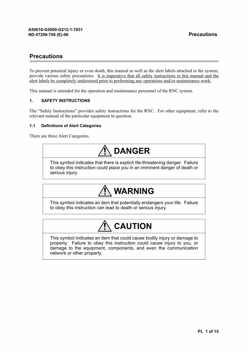
There are three Alert Categories.
DANGERThis symbol indicates that there is explicit life-threatening danger. Failureto obey this instruction could place you in an imminent danger of death orserious injury.
WARNINGThis symbol indicates an item that potentially endangers your life. Failureto obey this instruction can lead to death or serious injury.
CAUTIONThis symbol indicates an item that could cause bodily injury or damage toproperty. Failure to obey this instruction could cause injury to you, ordamage to the equipment, components, and even the communicationnetwork or other property.
A50016-G5000-G212-1-7631ND-57268-706 (E)-06 Precautions
PL 2 of 15
1.2 List of Alert Labels
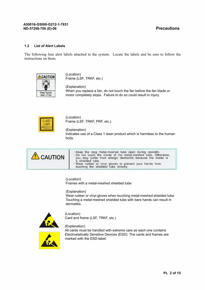
The following lists alert labels attached to the system. Locate the labels and be sure to follow theinstructions on them.
(Location)Frame (LSF, TRKF, etc.)
(Explanation)When you replace a fan, do not touch the fan before the fan blade or motor completely stops. Failure to do so could result in injury.
(Location)Frame (LSF, TRKF, PRF, etc.)
(Explanation)Indicates use of a Class 1 laser product which is harmless to the human body.
(Location)Frames with a metal-meshed shielded tube
(Explanation)Wear rubber or vinyl gloves when touching metal-meshed shielded tube. Touching a metal-meshed shielded tube with bare hands can result in dermatitis.
(Location)Card and frame (LSF, TRKF, etc.)
(Explanation)All cards must be handled with extreme care as each one contains Electrostatically Sensitive Devices (ESD). The cards and frames are marked with the ESD-label.
A50016-G5000-G212-1-7631ND-57268-706 (E)-06 Precautions
PL 3 of 15
1.3 List of Safety Instructions
When you find a safety instruction in this manual, be sure to read the instruction before starting thework.
The safety instructions, especially regarding death or injury, in this manual are listed below, by theiralert categories.
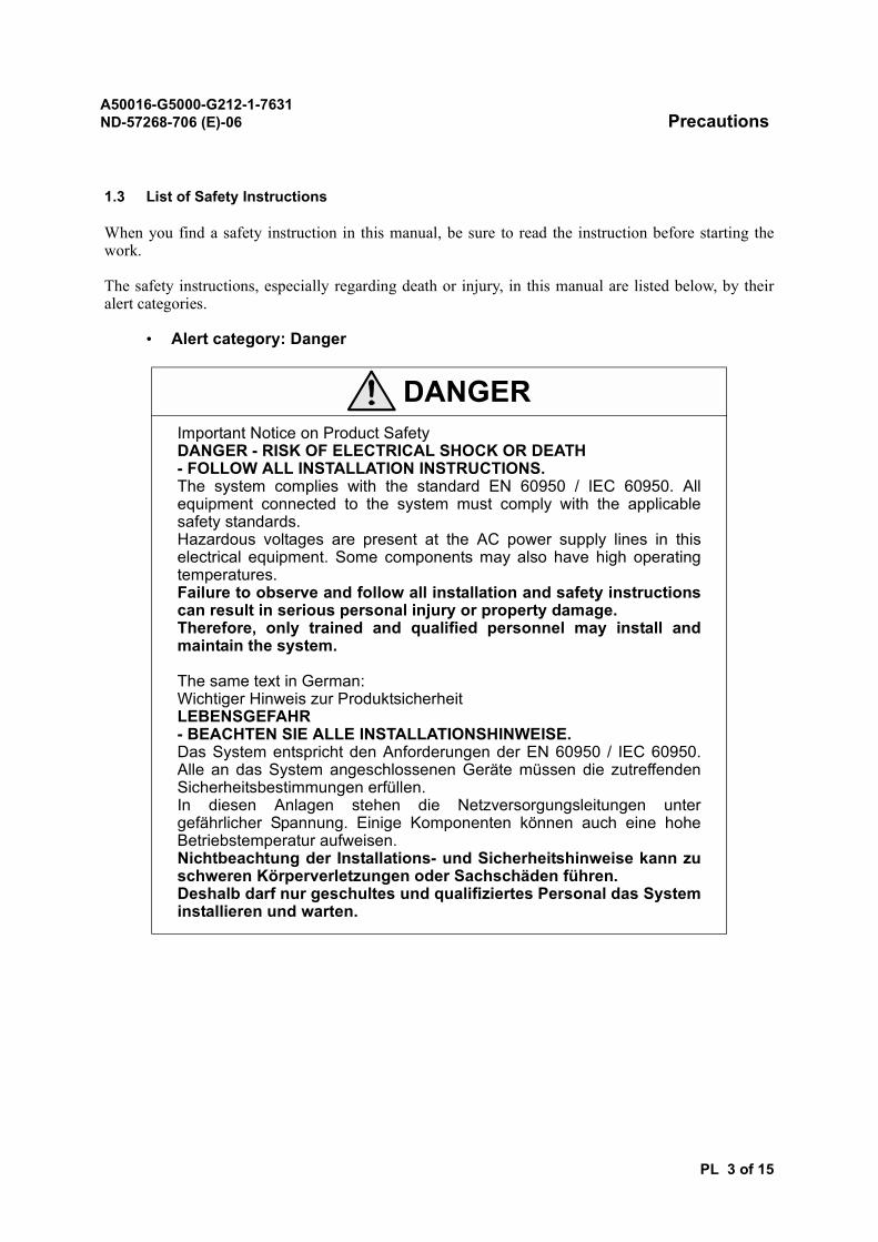
• Alert category: Danger
DANGERImportant Notice on Product SafetyDANGER - RISK OF ELECTRICAL SHOCK OR DEATH - FOLLOW ALL INSTALLATION INSTRUCTIONS.The system complies with the standard EN 60950 / IEC 60950. Allequipment connected to the system must comply with the applicablesafety standards.Hazardous voltages are present at the AC power supply lines in thiselectrical equipment. Some components may also have high operatingtemperatures.Failure to observe and follow all installation and safety instructionscan result in serious personal injury or property damage.Therefore, only trained and qualified personnel may install andmaintain the system.
The same text in German:Wichtiger Hinweis zur ProduktsicherheitLEBENSGEFAHR - BEACHTEN SIE ALLE INSTALLATIONSHINWEISE.Das System entspricht den Anforderungen der EN 60950 / IEC 60950.Alle an das System angeschlossenen Geräte müssen die zutreffendenSicherheitsbestimmungen erfüllen.In diesen Anlagen stehen die Netzversorgungsleitungen untergefährlicher Spannung. Einige Komponenten können auch eine hoheBetriebstemperatur aufweisen.Nichtbeachtung der Installations- und Sicherheitshinweise kann zuschweren Körperverletzungen oder Sachschäden führen.Deshalb darf nur geschultes und qualifiziertes Personal das Systeminstallieren und warten.

A50016-G5000-G212-1-7631ND-57268-706 (E)-06 Precautions
PL 4 of 15
• Alert category: Caution
CAUTIONThis equipment has been tested and found to comply with EN 300386. Itsclass of conformity is defined in table A30808-X3247-X910-*-7618, whichis shipped with each product. This class also corresponds to the limits fora Class A digital device, pursuant to part 15 of the FCC Rules.These limits are designed to provide reasonable protection againstharmful interference when the equipment is operated in a commercialenvironment.This equipment generates, uses and can radiate radio frequency energyand, if not installed and used in accordance with the relevant standardsreferenced in the manual "Guide to Documentation", may cause harmfulinterference to radio communications.For system installations it is strictly required to choose all installation sitesaccording to national and local requirements concerning constructionrules and static load capacities of buildings and roofs.For all sites, in particular in residential areas it is mandatory to observe allrespectively applicable electromagnetic field / force (EMF) limits.Otherwise harmful personal interference is possible.

A50016-G5000-G212-1-7631ND-57268-706 (E)-06 Precautions
PL 5 of 15
• Alert category: Caution (continued)
CAUTIONSafety instructions on the overall work:
• Before performing any operations and maintenance work, make surethat the working environment is safe.
• Before performing any operations and maintenance work, check thatthe emergency exit are clear in case of an emergency situation.
• Before performing any operation and maintenance work, make suresufficient safety instructions are given to maintenance personnel.
• Never wear slippers during work.• Take care not to trip over cables, components, or tools during work.
Failure to do so could result injury.• Take care that the shirt sleeves and trousers are not caught in
equipment and/or machines during work. Failure to do so couldcause an injury or other accident.
• Do not allow liquid, such as water, on system components or touchthe system with wet hands. Moisture in the system can cause anelectrical shock or a trouble to the system. If any liquid comes intocontact with the system, immediately turn off the power of the affectedcomponents, and request repairs.
• Do not rework or disassemble the system components. An electricalshock, fire or component and/or system failure could occur as aresult.
A50016-G5000-G212-1-7631ND-57268-706 (E)-06 Precautions
PL 6 of 15
• Alert category: Caution (continued)
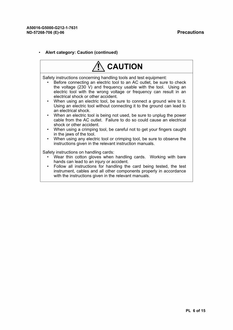
CAUTIONSafety instructions concerning handling tools and test equipment:
• Before connecting an electric tool to an AC outlet, be sure to checkthe voltage (230 V) and frequency usable with the tool. Using anelectric tool with the wrong voltage or frequency can result in anelectrical shock or other accident.
• When using an electric tool, be sure to connect a ground wire to it.Using an electric tool without connecting it to the ground can lead toan electrical shock.
• When an electric tool is being not used, be sure to unplug the powercable from the AC outlet. Failure to do so could cause an electricalshock or other accident.
• When using a crimping tool, be careful not to get your fingers caughtin the jaws of the tool.
• When using any electric tool or crimping tool, be sure to observe theinstructions given in the relevant instruction manuals.
Safety instructions on handling cards:• Wear thin cotton gloves when handling cards. Working with bare
hands can lead to an injury or accident.• Follow all instructions for handling the card being tested, the test
instrument, cables and all other components properly in accordancewith the instructions given in the relevant manuals.
A50016-G5000-G212-1-7631ND-57268-706 (E)-06 Precautions
PL 7 of 15
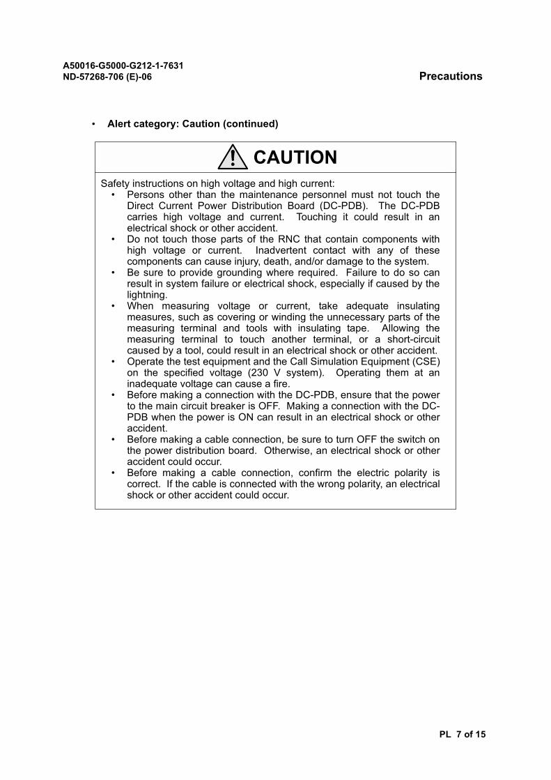
• Alert category: Caution (continued)
CAUTIONSafety instructions on high voltage and high current:
• Persons other than the maintenance personnel must not touch theDirect Current Power Distribution Board (DC-PDB). The DC-PDBcarries high voltage and current. Touching it could result in anelectrical shock or other accident.
• Do not touch those parts of the RNC that contain components withhigh voltage or current. Inadvertent contact with any of thesecomponents can cause injury, death, and/or damage to the system.
• Be sure to provide grounding where required. Failure to do so canresult in system failure or electrical shock, especially if caused by thelightning.
• When measuring voltage or current, take adequate insulatingmeasures, such as covering or winding the unnecessary parts of themeasuring terminal and tools with insulating tape. Allowing themeasuring terminal to touch another terminal, or a short-circuitcaused by a tool, could result in an electrical shock or other accident.
• Operate the test equipment and the Call Simulation Equipment (CSE)on the specified voltage (230 V system). Operating them at aninadequate voltage can cause a fire.
• Before making a connection with the DC-PDB, ensure that the powerto the main circuit breaker is OFF. Making a connection with the DC-PDB when the power is ON can result in an electrical shock or otheraccident.
• Before making a cable connection, be sure to turn OFF the switch onthe power distribution board. Otherwise, an electrical shock or otheraccident could occur.
• Before making a cable connection, confirm the electric polarity iscorrect. If the cable is connected with the wrong polarity, an electricalshock or other accident could occur.
A50016-G5000-G212-1-7631ND-57268-706 (E)-06 Precautions
PL 8 of 15
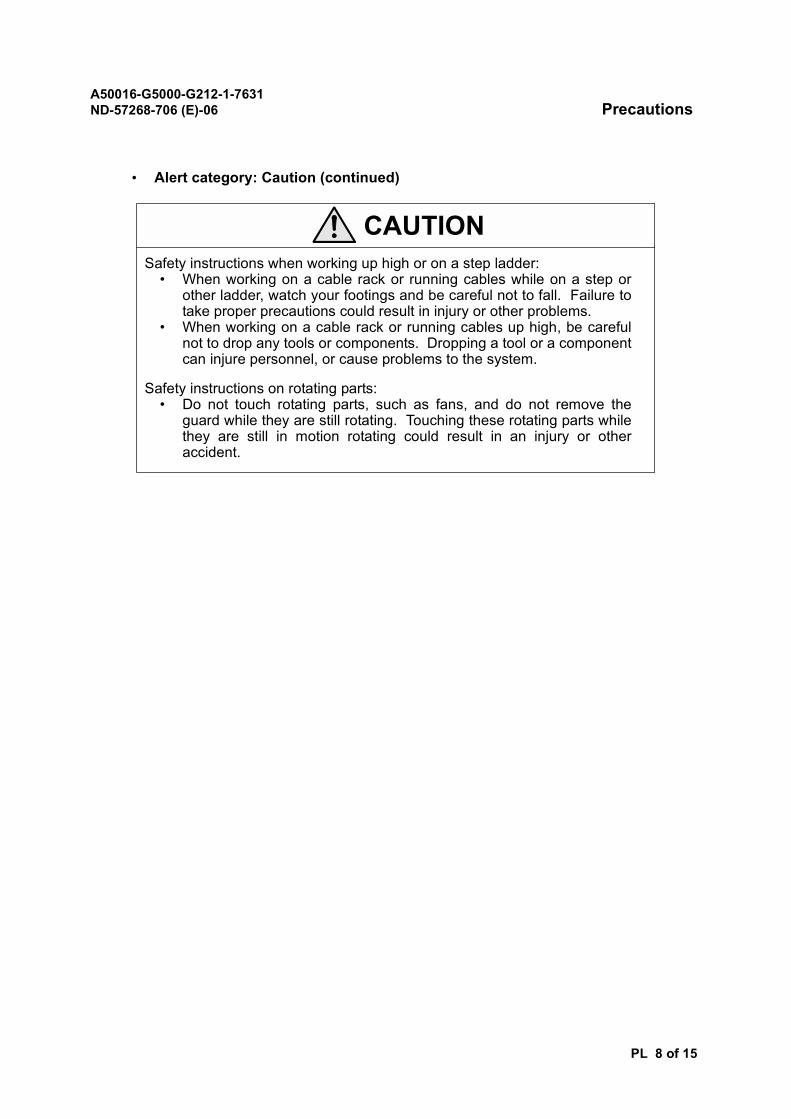
• Alert category: Caution (continued)
CAUTIONSafety instructions when working up high or on a step ladder:
• When working on a cable rack or running cables while on a step orother ladder, watch your footings and be careful not to fall. Failure totake proper precautions could result in injury or other problems.
• When working on a cable rack or running cables up high, be carefulnot to drop any tools or components. Dropping a tool or a componentcan injure personnel, or cause problems to the system.
Safety instructions on rotating parts:• Do not touch rotating parts, such as fans, and do not remove the
guard while they are still rotating. Touching these rotating parts whilethey are still in motion rotating could result in an injury or otheraccident.
A50016-G5000-G212-1-7631ND-57268-706 (E)-06 Precautions
PL 9 of 15
2. PRECAUTIONS FOR NORMAL SYSTEM OPERATION
The “Precautions for Normal System Operation” provides precautions against potential problems thatcould occur to the system. In order to maintain normal operation of the system, particular attentionmust be paid to each precaution prior to and during any operation and/or maintenance work.
2.1 Site Consideration
To maintain normal system operation, your site must always meet the requirements listed below.
(1) Temperature and humidity
• Make sure that the temperature and humidity levels are within the acceptable range: thetemperature must be between 5 and 40°C and the humidity 20 and 80% (There must beno condensation).
• Make sure that the site is not exposed to liquid such as water and oil.
• Make sure that the site is not exposed to direct sunlight nor placed near a flame orheating appliance like a stove.
(2) DustTo prevent a short circuit due to dust buildup, make sure that the site is kept clean and dustfree.
(3) VibrationSince the system components are precision-engineered equipment and devices, make surethat the site is not subject to vibration.
(4) Heat dissipationProper air circulation is necessary to prevent the temperature from rising inside the system.Make sure that the vents of the system components are always kept clear.
(5) Static electricityBe sure to connect your wrist strap to a proper ground such as an ESD terminal.
A50016-G5000-G212-1-7631ND-57268-706 (E)-06 Precautions
PL 10 of 15
2.2 List of Precautions
The precautions are listed by the following working situations:
• When Operating the System
• When Handling Cards
• When Handling the Power Supply
• When Handling Parts and Components
2.3 When Operating The System
• Keep the doors of the machine room closed during work. In a room with high humidity,vapor can condense on cards and modules in the RNC, which can lead to a short-circuit orfire. Excessive dust can also cause a short-circuit or fire.
• If using air-conditioning, prevent water from the ceiling or the refrigerant pipes fromdripping on cards and modules in the RNC. If any component in the system becomes wet,this could result in a short-circuit or fire.
• Keep the humidity in the machine room within the range of 20 to 80%, with no condensation.
• Do not leave foreign objects such as screws, wires, or pieces of metal inside the frames ormodules, Main Distribution Frame (MDF) or terminal devices of the RNC. Such foreignobjects can damage the equipment or cause a short-circuit, subsequently resulting in amalfunction of the RNC or other problem.
• Wear antistatic shoes during the operation and maintenance work.
• Clean the filter on the fan at least every six months. If the filter is not kept properly cleaned,a short-circuit or fire can occur.
A50016-G5000-G212-1-7631ND-57268-706 (E)-06 Precautions
PL 11 of 15
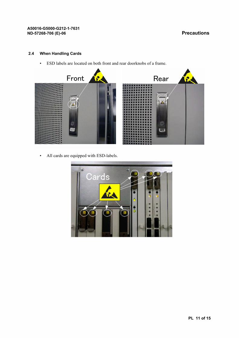
2.4 When Handling Cards
• ESD labels are located on both front and rear doorknobs of a frame.
• All cards are equipped with ESD-labels.
Front Rear
A50016-G5000-G212-1-7631ND-57268-706 (E)-06 Precautions
PL 12 of 15
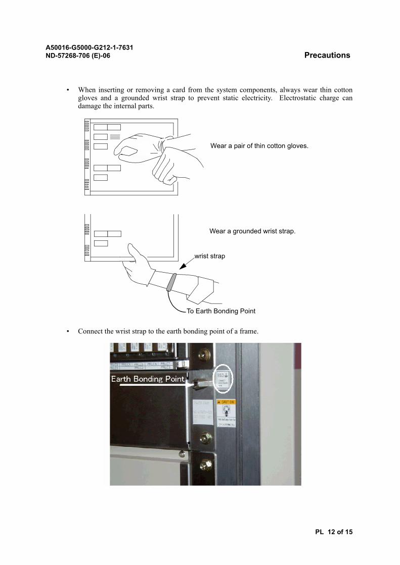
• When inserting or removing a card from the system components, always wear thin cottongloves and a grounded wrist strap to prevent static electricity. Electrostatic charge candamage the internal parts.
• Connect the wrist strap to the earth bonding point of a frame.
Wear a pair of thin cotton gloves.
Wear a grounded wrist strap.
To Earth Bonding Point
wrist strap
A50016-G5000-G212-1-7631ND-57268-706 (E)-06 Precautions
PL 13 of 15
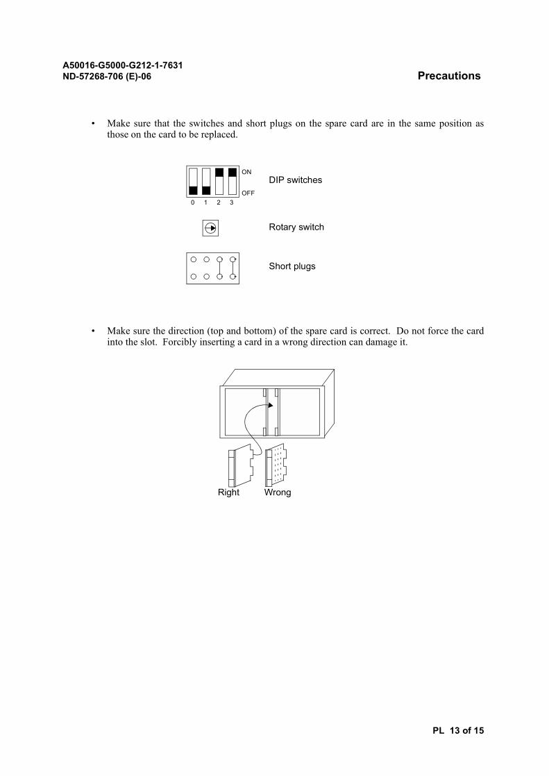
• Make sure that the switches and short plugs on the spare card are in the same position asthose on the card to be replaced.
• Make sure the direction (top and bottom) of the spare card is correct. Do not force the cardinto the slot. Forcibly inserting a card in a wrong direction can damage it.
0 1 2 3
ON
OFF
DIP switches
Rotary switch
Short plugs
Right Wrong
A50016-G5000-G212-1-7631ND-57268-706 (E)-06 Precautions
PL 14 of 15
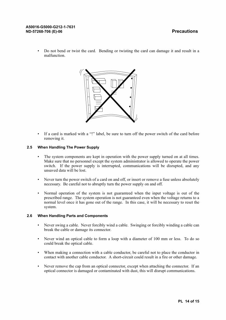
• Do not bend or twist the card. Bending or twisting the card can damage it and result in amalfunction.
• If a card is marked with a “!” label, be sure to turn off the power switch of the card beforeremoving it.
2.5 When Handling The Power Supply
• The system components are kept in operation with the power supply turned on at all times.Make sure that no personnel except the system administrator is allowed to operate the powerswitch. If the power supply is interrupted, communications will be disrupted, and anyunsaved data will be lost.
• Never turn the power switch of a card on and off, or insert or remove a fuse unless absolutelynecessary. Be careful not to abruptly turn the power supply on and off.
• Normal operation of the system is not guaranteed when the input voltage is out of theprescribed range. The system operation is not guaranteed even when the voltage returns to anormal level once it has gone out of the range. In this case, it will be necessary to reset thesystem.
2.6 When Handling Parts and Components
• Never swing a cable. Never forcibly wind a cable. Swinging or forcibly winding a cable canbreak the cable or damage its connector.
• Never wind an optical cable to form a loop with a diameter of 100 mm or less. To do socould break the optical cable.
• When making a connection with a cable conductor, be careful not to place the conductor incontact with another cable conductor. A short-circuit could result in a fire or other damage.
• Never remove the cap from an optical connector, except when attaching the connector. If anoptical connector is damaged or contaminated with dust, this will disrupt communications.
A50016-G5000-G212-1-7631ND-57268-706 (E)-06 Precautions
PL 15 of 15
• Never step on a battery. Stepping on a battery can cause the battery to leak.
• Use tools and components such as batteries and cables correctly, in accordance with theinstructions given in the relevant manuals.
3. DISPOSAL OF ELECTRICAL AND ELECTRONIC EQUIPMENT
All electrical and electronic products should be disposed of separately from the municipal waste streamvia designated collection facilities appointed by the government or the local authorities.
The correct disposal and separate collection of your old appliance will help prevent potential negativeconsequences for the environment and human health. It is a precondition for reuse and recycling ofused electrical and electronic equipment.
For more detailed information about disposal of your old appliance, please contact your salesrepresentative.
The statements quoted above are only fully valid for equipment which is installed in the countries of theEuropean Union and is covered by the directive 2002/96/EC.
Countries outside the European Union may have other regulations regarding the disposal of electricaland electronic equipment.
A50016-G5000-G212-1-7631 PrefaceND-57268-706 (E)-01
PR 1 of 1
Preface
This document is prepared as a standard edition that may include descriptions not applying to yoursystem.
This Installation Manual provides the installation personnel with the standard procedures, methods, andtechnical supplements for proper installation of the Radio Network Controller (RNC) which controlsthe radio base station(s) generally called Node B in the Wideband Code Division Multiple Access (W-CDMA) system.
This document is comprised of the following sections:
WORK FLOW AND INSTALLATION PROCESS CHARTSDescribes the work flow and installation process charts.
TASK LISTLists all procedures described in this manual.
PREPARATIONDescribes the preparation required for installation.
CARRYING CARGO AND QUANTITY CHECKDescribes procedures for carrying cargo and making quantity checks.
WORK IN SWITCHING ROOMDescribes procedures for work in the switching room.
WORK FOR CABLE RACK INSTALLATIONDescribes procedures for cable rack installation.
TECHNICAL SUPPLEMENTDescribes the technical supplement information.
INSTALLATION PARTSDescribes the installation parts.
TOOLSLists tools used for installation.
HOW TO READ INSTALLATION DRAWINGSDescribes how to read the installation drawings.
CHECK BEFORE POWER-ONDescribes check items as preparatory tests.

A50016-G5000-G212-1-7631ND-57268-706 (E)-01
DA-1 of 1
Reason for Update
Summary:
Preliminary edition
Details:
Issue History:
Chapter/Section Reason for Update
All Preliminary edition
Issue Number
Date of issue Reason for Update
Prelim 10/2005 Preliminary edition
A50016-G5000-G212-1-7631 ContentsND-57268-706 (E)-01
CL 1 of 3
Contents
(*:REVISION)
TITLE INDEX NUMBER
SECTION 1GENERAL
Work Flow and Installation Process Chart ....................... INT-090-1010-04(E)-01
Outline ............................................................................. INT-090-1050-01(E)-01
SECTION 2TASK LIST
Task List ........................................................................... INT-090-9999-03(E)-02
SECTION 3PREPARATION
Preparation ...................................................................... PRC-090-2010-02(E)-01
SECTION 4CARRYING CARGO AND QUANTITY CHECK
Carrying Cargo into the Exchange Office ........................ PRC-090-3010-02(E)-01
Quantity Check ................................................................ PRC-090-3020-02(E)-01
SECTION 5WORK IN SWITCHING ROOM
Installing Equipment Frame ............................................. PRC-090-4010-03(E)-03
Installing DC-PDB............................................................ PRC-090-4020-02(E)-01
Installing AALP and VALP................................................ PRC-090-4030-02(E)-01
Installing Maintenance Equipment ................................... PRC-090-4040-02(E)-01
Card Insertion .................................................................. PRC-090-4050-02(E)-01
Module and Card Allocation Check ................................. PRC-090-4060-02(E)-01
DC-Power Cable Laying .................................................. PRC-090-4070-02(E)-02
Earth and Frame Earth Cable Laying .............................. PRC-090-4080-02(E)-02
Laying Power Cable for Maintenance Equipment............ PRC-090-4090-02(E)-01
Cable Preparation ............................................................ PRC-090-4100-02(E)-01
Interframe Cable Connection........................................... PRC-090-4110-02(E)-01
Optic Fiber Cable Connection.......................................... PRC-090-4120-02(E)-01
Optic Fiber Cable Laying ................................................. PRC-090-4130-02(E)-01
A50016-G5000-G212-1-7631 ContentsND-57268-706 (E)-01
CL 2 of 3
Laying Cable between the Switches and Distribution Frames (DF) .................................................................... PRC-090-4140-02(E)-01
Alarm Panel Cable Connections from DF........................ PRC-090-4150-02(E)-01
DTI Cable Laying ............................................................. PRC-090-4160-02(E)-02
Cable Connecting Position .............................................. PRC-090-4165-02(E)-03
Cabling Test ..................................................................... PRC-090-4170-02(E)-01
Forming and Securing the Laid Cables ........................... PRC-090-4220-02(E)-01
Cable Continuity Test ....................................................... PRC-090-4230-02(E)-01
Mounting End Cover with Aisle Alarm Lamp ................... PRC-090-4240-02(E)-01
Marking Equipment Frames............................................. PRC-090-4250-02(E)-01
Installing Cable Rack Covers and Frame Covers ............ PRC-090-4260-02(E)-01
Ethernet Cable Laying ..................................................... PRC-090-4270-02(E)-01
SECTION 6WORK FOR CABLE RACK INSTALLATION
Installing Cable Rack in Switching and Distribution Frame (DF) ...................................................................... PRC-090-5010-02(E)-01
SECTION 7TECHNICAL SUPPLEMENT
Cargo ............................................................................... APP-090-6010-02(E)-01
Marking ............................................................................ APP-090-6020-02(E)-01
Drilling.............................................................................. APP-090-6030-02(E)-01
Leveling ........................................................................... APP-090-6040-02(E)-01
Metal Working .................................................................. APP-090-6050-02(E)-01
Cable Termination with Crimp Terminal ........................... APP-090-6060-03(E)-01
Cable End Treatment....................................................... APP-090-6070-03(E)-01
Wire Wrapping ................................................................. APP-090-6080-02(E)-01
Cable Tying...................................................................... APP-090-6090-02(E)-01
Making DTI Cable ............................................................ APP-090-6100-02(E)-01
SECTION 8INSTALLATION PARTS
Crimp Terminal................................................................. APP-090-7010-03(E)-01
TITLE INDEX NUMBER
A50016-G5000-G212-1-7631 ContentsND-57268-706 (E)-01
CL 3 of 3
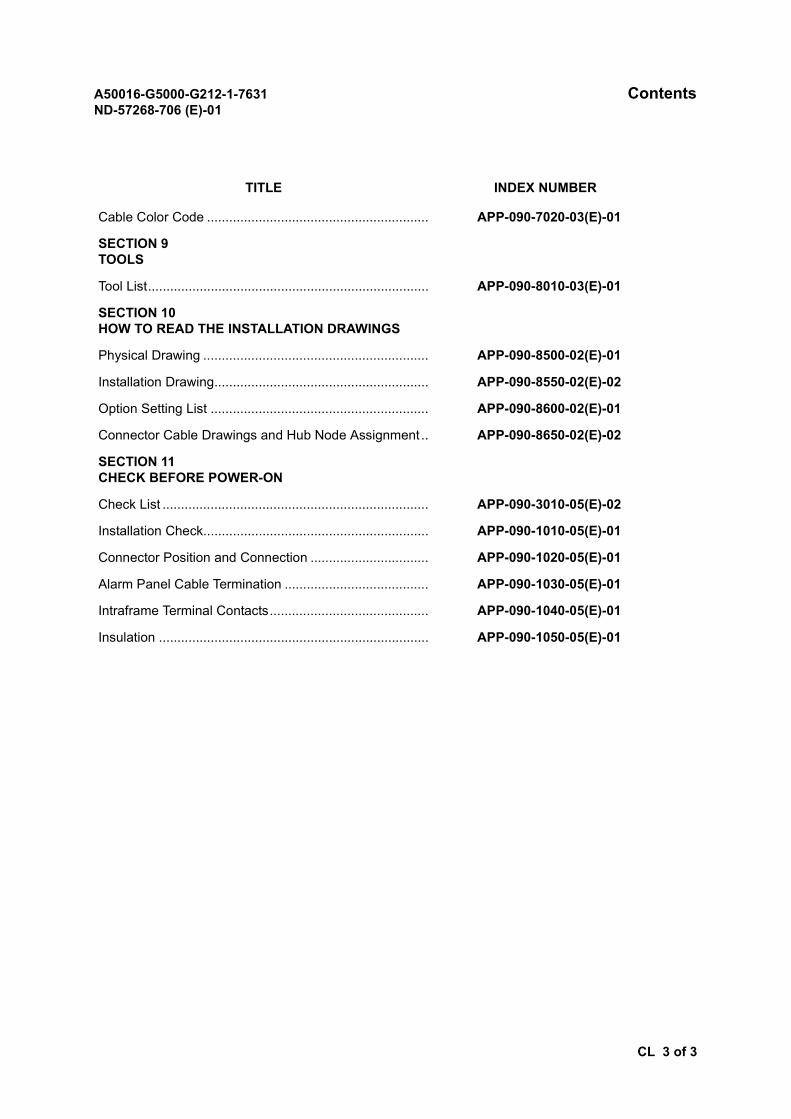
Cable Color Code ............................................................ APP-090-7020-03(E)-01
SECTION 9TOOLS
Tool List............................................................................ APP-090-8010-03(E)-01
SECTION 10HOW TO READ THE INSTALLATION DRAWINGS
Physical Drawing ............................................................. APP-090-8500-02(E)-01
Installation Drawing.......................................................... APP-090-8550-02(E)-02
Option Setting List ........................................................... APP-090-8600-02(E)-01
Connector Cable Drawings and Hub Node Assignment .. APP-090-8650-02(E)-02
SECTION 11CHECK BEFORE POWER-ON
Check List ........................................................................ APP-090-3010-05(E)-02
Installation Check............................................................. APP-090-1010-05(E)-01
Connector Position and Connection ................................ APP-090-1020-05(E)-01
Alarm Panel Cable Termination ....................................... APP-090-1030-05(E)-01
Intraframe Terminal Contacts........................................... APP-090-1040-05(E)-01
Insulation ......................................................................... APP-090-1050-05(E)-01
TITLE INDEX NUMBER

A50016-G5000-G212-1-7631ND-57268-706 (E)-01
SECTION 1GENERAL
A50016-G5000-G212-1-7631 Work Flow Installation Process ChartINT-090-1010-04 (E)-01
INT-090-1010 1 of 7
Work Flow and Installation Process Chart
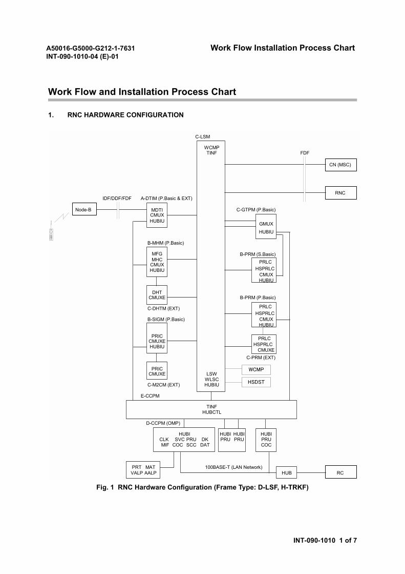
1. RNC HARDWARE CONFIGURATION
Fig. 1 RNC Hardware Configuration (Frame Type: D-LSF, H-TRKF)
C-LSM
WCMPTINF FDF
IDF/DDF/FDF A-DTIM (P.Basic & EXT)
MDTI C-GTPM (P.Basic)CMUXHUBIU
HUBIU
B-MHM (P.Basic)
MFG B-PRM (S.Basic)MHC
CMUXHUBIU
DHTCMUXE B-PRM (P.Basic)
C-DHTM (EXT)
B-SIGM (P.Basic)
PRICCMUXE PRLC
HUBIUCMUXE
C-PRM (EXT)
PRICCMUXE LSW
WLSCC-M2CM (EXT) HUBIU
E-CCPM
TINFHUBCTL
D-CCPM (OMP)
HUBI HUBI HUBI HUBICLK SVC PRU DK PRU PRU PRUMIF COC SCC DAT COC
PRT MAT 100BASE-T (LAN Network)VALP AALP HUB RC
Node-B
GMUX
CN (MSC)
RNC
WCMP
HSDST
PRLC
CMUXHUBIU
HSPRLC
PRLC
CMUXHUBIU
HSPRLC
HSPRLC
A50016-G5000-G212-1-7631 Work Flow Installation Process ChartINT-090-1010-04 (E)-01
INT-090-1010 2 of 7
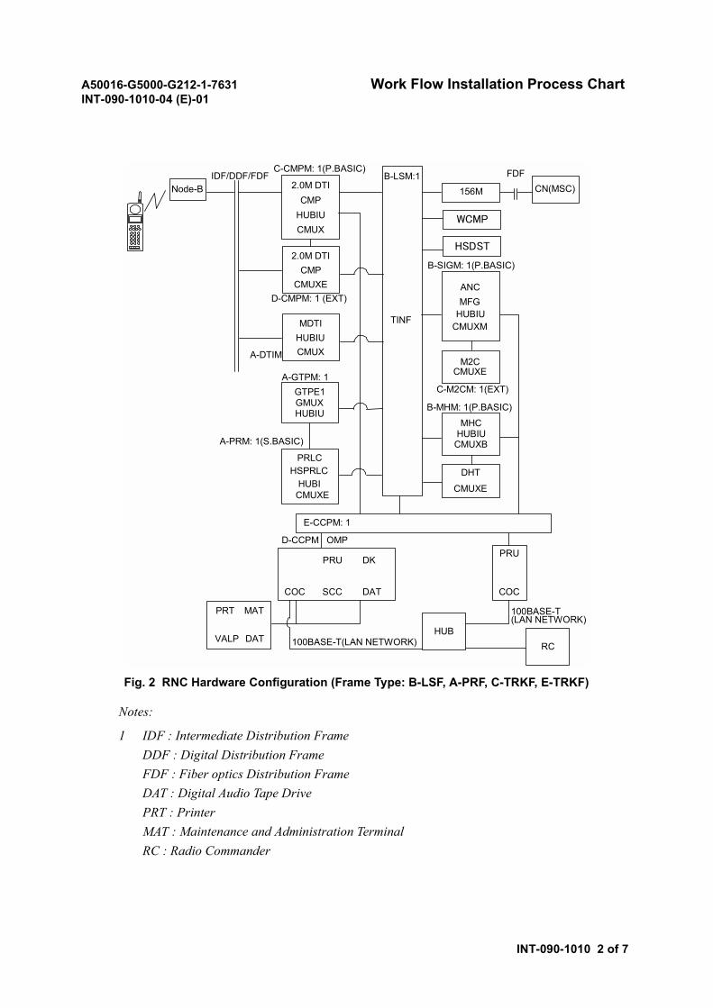
Fig. 2 RNC Hardware Configuration (Frame Type: B-LSF, A-PRF, C-TRKF, E-TRKF)
Notes:
1 IDF : Intermediate Distribution FrameDDF : Digital Distribution FrameFDF : Fiber optics Distribution FrameDAT : Digital Audio Tape DrivePRT : PrinterMAT : Maintenance and Administration TerminalRC : Radio Commander
TINF
B-LSM:12.0M DTI
CMPHUBIUCMUX
E-CCPM: 1
GTPE1GMUXHUBIU
PRLCHSPRLC
HUBI
A-GTPM: 1
A-PRM: 1(S.BASIC)
156M
ANCMFG
HUBIUCMUXM
M2CCMUXE
C-M2CM: 1(EXT)
B-MHM: 1(P.BASIC)
MHCHUBIUCMUXB
DHT
CMUXE
FDFCN(MSC)
B-SIGM: 1(P.BASIC)
C-CMPM: 1(P.BASIC)IDF/DDF/FDF
Node-B
OMPD-CCPM
PRU
SCC
DK
DATCOC
PRU
COC
PRT
VALP
MAT
DATHUB
100BASE-T(LAN NETWORK)
100BASE-T(LAN NETWORK)
RC
CMUXE
WCMP
HSDST2.0M DTI
CMPCMUXE
D-CMPM: 1 (EXT)
MDTIHUBIUCMUXA-DTIM
A50016-G5000-G212-1-7631 Work Flow Installation Process ChartINT-090-1010-04 (E)-01
INT-090-1010 3 of 7
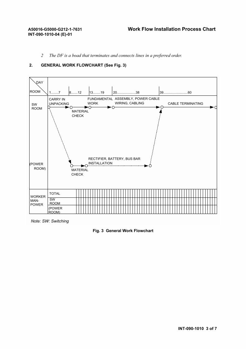
2 The DF is a boad that terminates and connects lines in a preferred order.
2. GENERAL WORK FLOWCHART (See Fig. 3)
Fig. 3 General Work Flowchart
DAY
ROOM
SWROOM
CARRY INUNPACKING
MATERIALCHECK
ASSEMBLY, POWER CABLEWIRING, CABLING CABLE TERMINATING
RECTIFIER, BATTERY, BUS BARINSTALLATION
MATERIALCHECK
(POWER ROOM)
WORKERMAN-POWER
TOTAL
SWROOM
(POWERROOM)
1........7 8.......12 13........19 20....................38 39..........................60
FUNDAMENTALWORK
Note: SW: Switching
A50016-G5000-G212-1-7631 Work Flow Installation Process ChartINT-090-1010-04 (E)-01
INT-090-1010 4 of 7
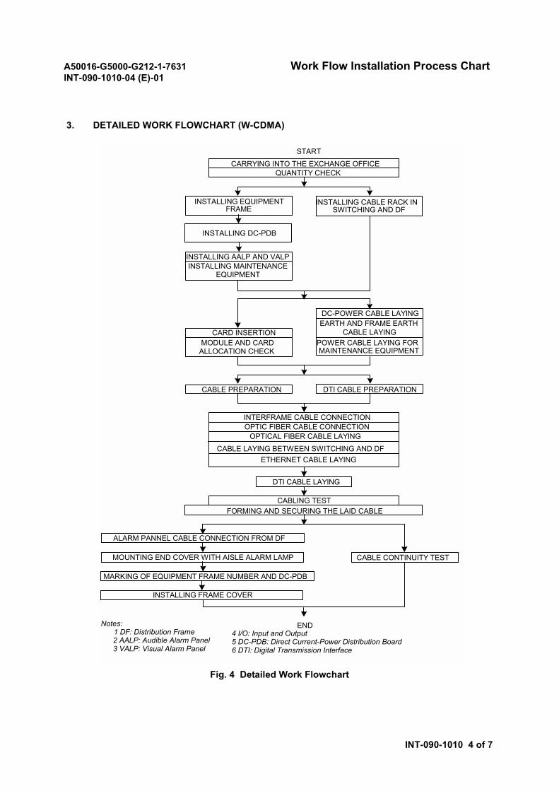
3. DETAILED WORK FLOWCHART (W-CDMA)
Fig. 4 Detailed Work Flowchart
INSTALLING AALP AND VALPINSTALLING MAINTENANCE
EQUIPMENT
CARD INSERTIONMODULE AND CARDALLOCATION CHECK
DC-POWER CABLE LAYINGEARTH AND FRAME EARTH
CABLE LAYINGPOWER CABLE LAYING FORMAINTENANCE EQUIPMENT
CABLE PREPARATION DTI CABLE PREPARATION
INTERFRAME CABLE CONNECTION
OPTICAL FIBER CABLE LAYING
CABLE LAYING BETWEEN SWITCHING AND DF
START
CARRYING INTO THE EXCHANGE OFFICEQUANTITY CHECK
INSTALLING EQUIPMENTFRAME
INSTALLING CABLE RACK INSWITCHING AND DF
INSTALLING DC-PDB
CABLE CONTINUITY TEST
CABLING TESTFORMING AND SECURING THE LAID CABLE
ALARM PANNEL CABLE CONNECTION FROM DF
MOUNTING END COVER WITH AISLE ALARM LAMP
MARKING OF EQUIPMENT FRAME NUMBER AND DC-PDB
INSTALLING FRAME COVER
DTI CABLE LAYING
ENDNotes:1 DF: Distribution Frame
2 AALP: Audible Alarm Panel 3 VALP: Visual Alarm Panel
4 I/O: Input and Output 5 DC-PDB: Direct Current-Power Distribution Board 6 DTI: Digital Transmission Interface
ETHERNET CABLE LAYING
OPTIC FIBER CABLE CONNECTION
A50016-G5000-G212-1-7631 Work Flow Installation Process ChartINT-090-1010-04 (E)-01
INT-090-1010 5 of 7
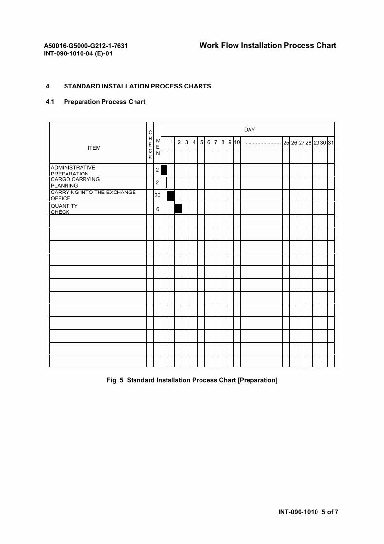
4. STANDARD INSTALLATION PROCESS CHARTS
4.1 Preparation Process Chart
Fig. 5 Standard Installation Process Chart [Preparation]
ITEM
ADMINISTRATIVEPREPARATIONCARGO CARRYINGPLANNINGCARRYING INTO THE EXCHANGEOFFICEQUANTITYCHECK
CHECK
MEN
DAY
2
2
20
6
1 2 3 4 5 6 7 8 9 10 25 26 2728 2930 31.........................
A50016-G5000-G212-1-7631 Work Flow Installation Process ChartINT-090-1010-04 (E)-01
INT-090-1010 6 of 7
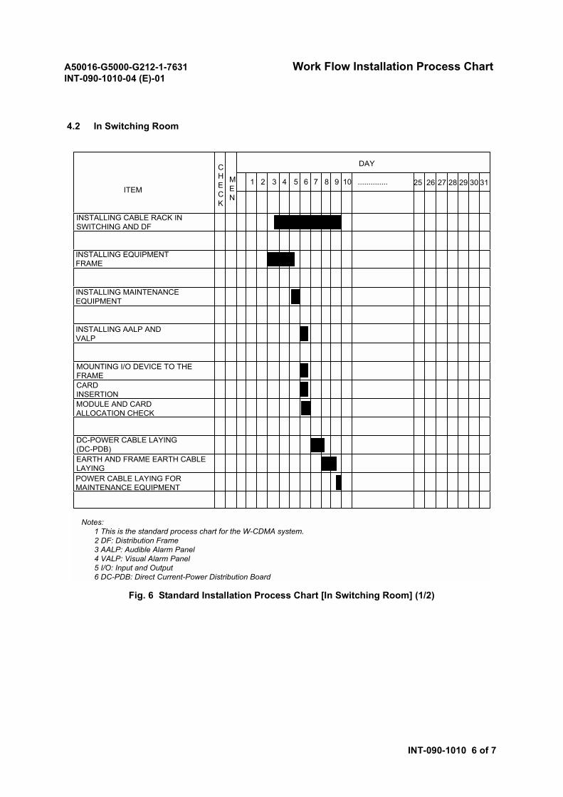
4.2 In Switching Room
Fig. 6 Standard Installation Process Chart [In Switching Room] (1/2)
Notes: 1 This is the standard process chart for the W-CDMA system. 2 DF: Distribution Frame
3 AALP: Audible Alarm Panel 4 VALP: Visual Alarm Panel 5 I/O: Input and Output 6 DC-PDB: Direct Current-Power Distribution Board
ITEM
INSTALLING CABLE RACK INSWITCHING AND DF
INSTALLING EQUIPMENTFRAME
INSTALLING MAINTENANCEEQUIPMENT
CHECK
MEN
DAY
1 2 3 4 5 6 7 8 9 10 25 26 27 28 29 30 31..............
INSTALLING AALP ANDVALP
CARDINSERTION
DC-POWER CABLE LAYING(DC-PDB)
POWER CABLE LAYING FORMAINTENANCE EQUIPMENT
MODULE AND CARDALLOCATION CHECK
MOUNTING I/O DEVICE TO THEFRAME
EARTH AND FRAME EARTH CABLELAYING
A50016-G5000-G212-1-7631 Work Flow Installation Process ChartINT-090-1010-04 (E)-01
INT-090-1010 7 of 7
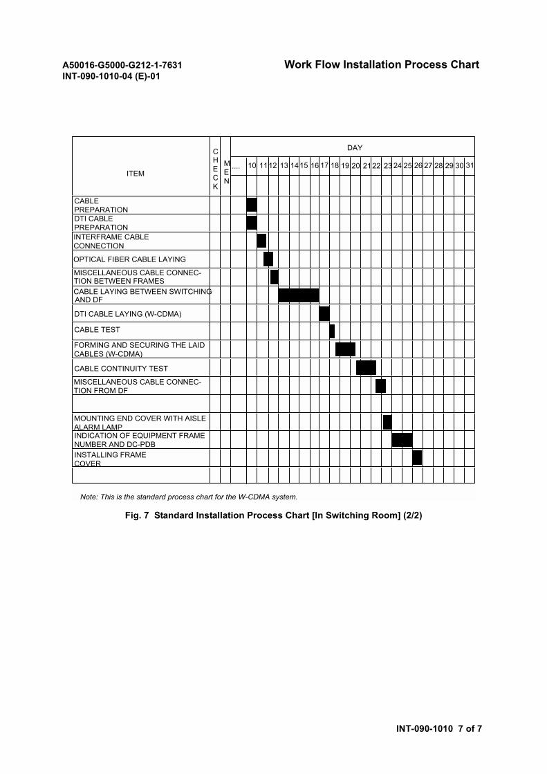
Fig. 7 Standard Installation Process Chart [In Switching Room] (2/2)
ITEM
CHECK
MEN
DAY
DTI CABLE LAYING (W-CDMA)
CABLE CONTINUITY TEST
Note: This is the standard process chart for the W-CDMA system.
OPTICAL FIBER CABLE LAYING
CABLE LAYING BETWEEN SWITCHINGAND DF
CABLE TEST
10 1112 13 1415 16 17 18 19 20 2122 23 24 25 26 27 28 29 30 31....
FORMING AND SECURING THE LAIDCABLES (W-CDMA)
CABLEPREPARATIONDTI CABLEPREPARATIONINTERFRAME CABLECONNECTION
MISCELLANEOUS CABLE CONNEC-TION BETWEEN FRAMES
INDICATION OF EQUIPMENT FRAMENUMBER AND DC-PDB
MISCELLANEOUS CABLE CONNEC-TION FROM DF
MOUNTING END COVER WITH AISLEALARM LAMP
INSTALLING FRAMECOVER
A50016-G5000-G212-1-7631INT-091-1050-01 (E)-01 Outline
INT-091-1050 1 of 2
Outline
1. OUTLINE OF INSTALLATION WORK
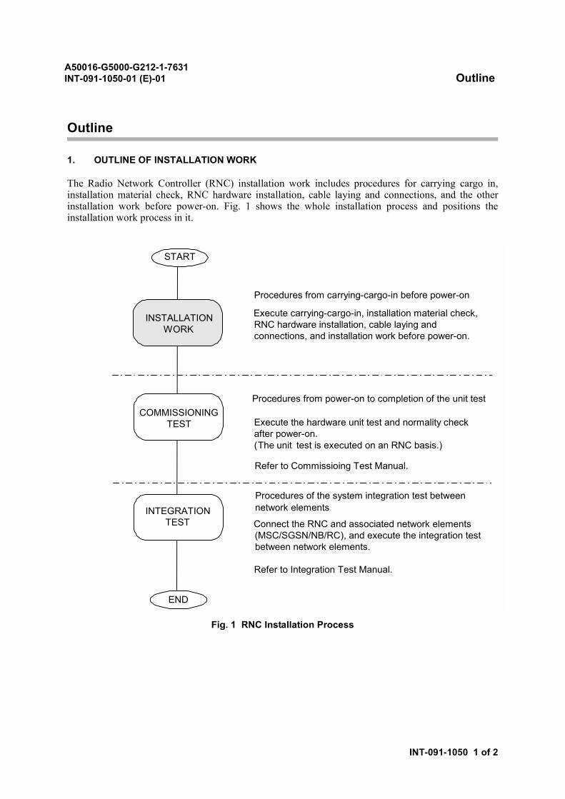
The Radio Network Controller (RNC) installation work includes procedures for carrying cargo in,installation material check, RNC hardware installation, cable laying and connections, and the otherinstallation work before power-on. Fig. 1 shows the whole installation process and positions theinstallation work process in it.
Fig. 1 RNC Installation Process
Procedures from carrying-cargo-in before power-on
Execute carrying-cargo-in, installation material check,RNC hardware installation, cable laying andconnections, and installation work before power-on.
Execute the hardware unit test and normality checkafter power-on.(The unit test is executed on an RNC basis.)
Procedures from power-on to completion of the unit test
Procedures of the system integration test between
Connect the RNC and associated network elements(MSC/SGSN/NB/RC), and execute the integration testbetween network elements.
Refer to Integration Test Manual.
Refer to Commissioing Test Manual.
END
START
INSTALLATIONWORK
COMMISSIONINGTEST
INTEGRATIONTEST
network elements
A50016-G5000-G212-1-7631INT-091-1050-01 (E)-01 Outline
INT-091-1050 2 of 2
2. INSTALLATION WORK PROCESS
The installation work process includes the following items:
• PreparationIncludes the administrative preparation and the planning for carrying in of the cargo.
• Carrying cargo and quantity checkIncludes cautions for carrying cargo, practical way of carrying, unpacking, and material listcheck.
• Work in exchange roomExplains procedures for work done in the exchange room step by step.
• Work for cable rack installationExplains procedures of the cable rack installation.
• Check before power-onChecks if power-on can be done before starting the commissioning test after completing theinstallation work.
3. SUPPLEMENTARY INFORMATION FOR INSTALLATION WORK
For the installation work, the supplementary information gives various techniques, installation partsand tools, installation drawings, and check before power-on.
• Technical supplementExplains various installation techniques.
• Installation partsExplains the crimp terminal and the cable color code.
• ToolsExplains how to use tools, drill, cutter, etc.
• How to read installation drawingsExplains how to reference and use installation drawings.
• Check before power-onExplains procedures for installation check, connector position and connection, alarm panelcable termination, interframe terminal contacts, insulation, and attaches their check sheets.

A50016-G5000-G212-1-7631ND-57268-706 (E)-01
SECTION 2TASK LIST

A50016-G5000-G212-1-7631 Task ListINT-090-9999-03 (E)-02
INT-090-9999 1 of 3
Task List
1. PREPARATION
• Preparation
2. CARRYING CARGO AND QUANTITY CHECK
• Carrying Cargo into the Exchange Office
• Quantity Check
3. WORK IN SWITCHING ROOM
• Installing Equipment Frame
• Installing DC-PDB
• Installing AALP and VALP
• Installing Maintenance Equipment
• Card Insertion
• Module and Card Allocation Check
• DC-Power Cable Laying
• Earth and Frame Earth Cable Laying
• Laying Power Cable for Maintenance Equipment
• Cable Preparation
• Interframe Cable Connection
• Optic Fiber Cable Connection
• Optic Fiber Cable Laying
• Laying Cable between the Switches and Distribution Frames (DF)
• Alarm Panel Cable Connections from DF
CAUTIONPlease read the Precautions before performing each task.

A50016-G5000-G212-1-7631 Task ListINT-090-9999-03 (E)-02
INT-090-9999 2 of 3
• DTI Cable Laying
• Cable Connecting Position
• Cabling Test
• Forming and Securing the Laid Cables
• Cable Continuity Test
• Mounting End Cover with Aisle Alarm Lamp
• Marking Equipment Frames
• Installing Cable Rack Covers and Frame Covers
• Ethernet Cable Laying
4. WORK FOR CABLE RACK INSTALLATION
• Installing Cable Rack in Switching and Distribution Frame (DF)
5. TECHNICAL SUPPLEMENT
• Cargo
• Marking
• Drilling
• Leveling
• Metal Working
• Cable Termination with Crimp Terminal
• Cable End Treatment
• Wire Wrapping
• Cable Tying
• Making DTI Cable
A50016-G5000-G212-1-7631 Task ListINT-090-9999-03 (E)-02
INT-090-9999 3 of 3
6. INSTALLATION PARTS
• Crimp Terminal
• Cable Color Code
7. TOOLS
• Tool List
8. HOW TO READ THE INSTALLATION DRAWINGS
• Physical Drawing
• Installation Drawing
• Option Setting List
• Connector Cable Drawings and Hub Node Assignment
9. CHECK BEFORE POWER-ON
• Check List
• Installation Check
• Connector Position and Connection
• Alarm Panel Cable Termination
• Intraframe Terminal Contacts
• Insulation

A50016-G5000-G212-1-7631ND-57268-706 (E)-01
SECTION 3PREPARATION
A50016-G5000-G212-1-7631 PreparationPRC-090-2010-02 (E)-01
PRC-090-2010 1 of 3
Preparation
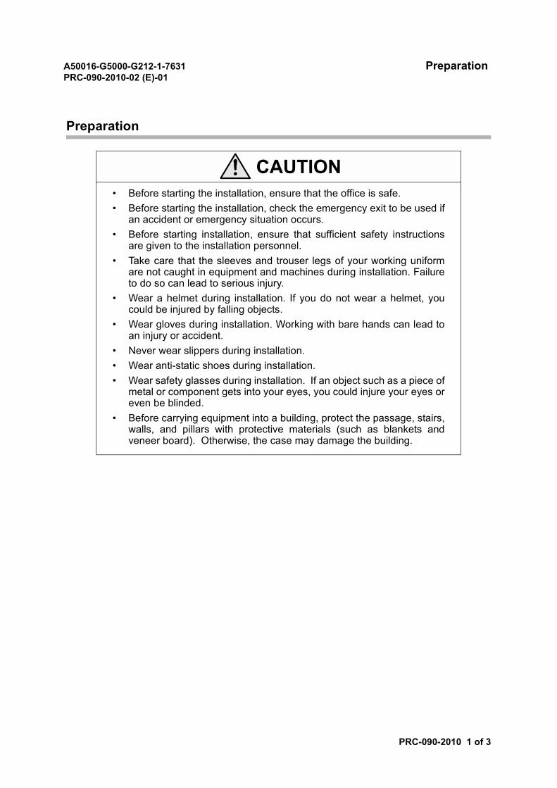
CAUTION• Before starting the installation, ensure that the office is safe.• Before starting the installation, check the emergency exit to be used if
an accident or emergency situation occurs.• Before starting installation, ensure that sufficient safety instructions
are given to the installation personnel.• Take care that the sleeves and trouser legs of your working uniform
are not caught in equipment and machines during installation. Failureto do so can lead to serious injury.
• Wear a helmet during installation. If you do not wear a helmet, youcould be injured by falling objects.
• Wear gloves during installation. Working with bare hands can lead toan injury or accident.
• Never wear slippers during installation.• Wear anti-static shoes during installation.• Wear safety glasses during installation. If an object such as a piece of
metal or component gets into your eyes, you could injure your eyes oreven be blinded.
• Before carrying equipment into a building, protect the passage, stairs,walls, and pillars with protective materials (such as blankets andveneer board). Otherwise, the case may damage the building.

A50016-G5000-G212-1-7631 PreparationPRC-090-2010-02 (E)-01
PRC-090-2010 2 of 3
1. REVIEW OF PRECAUTIONARY MEASURES
Review precautions for inland transportation, storage, and installation. Throughout the installation,safety is most important.
1.1 During inland transportation and storage
(1) Load and unload cargo carefully.
(2) Use a covered truck to transport cargo from the port to the exchange office.
(3) Protect the cargo from damage due to shock.
(4) Protect the cargo from fire, rain, water, dust, moisture, and theft during storage.
(5) Pay special attention to protect buildings, facilities, and equipment.
1.2 During installation
(1) Observe proper manners and maintain good relationship with the customers.
(2) Observe rules established in the exchange office.
(3) Keep to the standard working hours and schedule.
(4) Cooperate with the fellow workers and local personnel.
(5) Hold morning meetings every day to carry out the day’s work efficiently.
(6) Go through the procedures for reporting emergencies and unsafe work conditions.
(7) Prepare a first aid box.
(8) Beware of fire and assign a person to be in charge in case a fire breaks out.
(9) Smoke only in designated areas and use ash trays; do not smoke in the working room.
(10) Lock all storage rooms.
(11) After completing a day's work, ensure that the work area is neat and orderly. This will makethe next day's work more efficient.
(12) Arrange installation materials and tools on the specified floor area and check them.
(13) Clean up each work area and keep the cleaning tools in order.
(14) Clean the floor and return unused materials to their designated place.
(15) Prevent accumulation of dust, and litter garbage frequently to keep the site clean.
(16) Take care not to damage the building and facilities.

A50016-G5000-G212-1-7631 PreparationPRC-090-2010-02 (E)-01
PRC-090-2010 3 of 3
(17) Wear proper working clothes and shoes.
(18) Wear a safety helmet in hazardous work areas.
(19) Check that the scaffolds, ladders, and stepladders are working properly and safe, beforestarting work.
(20) Assign an observer when working in high or dangerous places to avoid accidents.
(21) Check that all electric machines, tools, and facilities have been turned off after finishingwork.
1.3 In addition to the above, observe the following
To prevent car accidents, observe the local traffic regulations and laws. It is especially important toobserve speed limits, to use seat belts, and to never drive while under the influence of alcohol or drugs.
2. ADMINISTRATIVE PREPARATION
To determine general administration matters:
(1) Prepare a temporary telephone line for use during installation, if necessary.
(2) Inform technicians and workers of any updates or changes in the schedule.
(3) Determine when to have break times and the rest areas, and check the working hours andrules in the exchange office.
(4) Go through the procedures for safe work conditions.
(5) Determine the emergency reporting procedures.
(6) Prepare various installation forms.
3. CARGO CARRYING PLANNING
To determine the routes to carry the cargo in and temporary unpacking and storage locations prior tocarrying the cargo into the exchange office:
(1) Determine the route to carry the cargo in.
(2) Prepare temporary storage area or space.
(3) Prepare unpacking space.
(4) Prevent damage to the building facilities (pillars, floors, walls, etc.).

A50016-G5000-G212-1-7631ND-57268-706 (E)-01
SECTION 4CARRYING CARGO AND QUANTITY CHECK
A50016-G5000-G212-1-7631 Carrying Cargo into the Exchange OfficePRC-090-3010-02 (E)-01
PRC-090-3010 1 of 9
Carrying Cargo into the Exchange Office
1. PROCEDURE
STEP ACTION/REMARKS
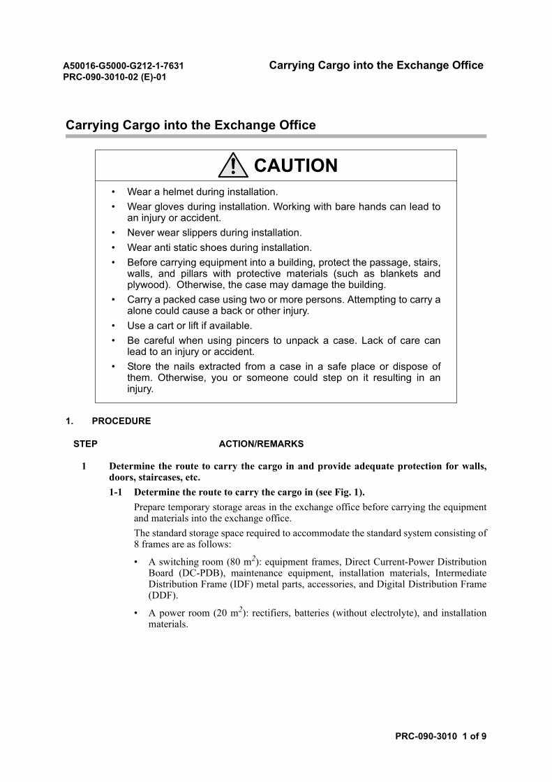
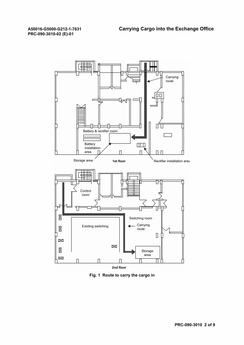
1 Determine the route to carry the cargo in and provide adequate protection for walls,doors, staircases, etc.1-1 Determine the route to carry the cargo in (see Fig. 1).
Prepare temporary storage areas in the exchange office before carrying the equipmentand materials into the exchange office.The standard storage space required to accommodate the standard system consisting of8 frames are as follows:
• A switching room (80 m2): equipment frames, Direct Current-Power DistributionBoard (DC-PDB), maintenance equipment, installation materials, IntermediateDistribution Frame (IDF) metal parts, accessories, and Digital Distribution Frame(DDF).
• A power room (20 m2): rectifiers, batteries (without electrolyte), and installationmaterials.
CAUTION• Wear a helmet during installation.• Wear gloves during installation. Working with bare hands can lead to
an injury or accident.• Never wear slippers during installation.• Wear anti static shoes during installation.• Before carrying equipment into a building, protect the passage, stairs,
walls, and pillars with protective materials (such as blankets andplywood). Otherwise, the case may damage the building.
• Carry a packed case using two or more persons. Attempting to carry aalone could cause a back or other injury.
• Use a cart or lift if available.• Be careful when using pincers to unpack a case. Lack of care can
lead to an injury or accident.• Store the nails extracted from a case in a safe place or dispose of
them. Otherwise, you or someone could step on it resulting in aninjury.
A50016-G5000-G212-1-7631 Carrying Cargo into the Exchange OfficePRC-090-3010-02 (E)-01
PRC-090-3010 2 of 9
Fig. 1 Route to carry the cargo in
Batteryinstallationarea
Carryingroute
Battery & rectifier room
Storage area Rectifier installation area1st floor
Controlroom
Carryingroute
Switching room
Existing switching
2nd floor
Storagearea
A50016-G5000-G212-1-7631 Carrying Cargo into the Exchange OfficePRC-090-3010-02 (E)-01
PRC-090-3010 3 of 9
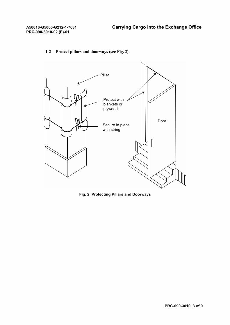
1-2 Protect pillars and doorways (see Fig. 2).
Fig. 2 Protecting Pillars and Doorways
Pillar
Protect withblankets orplywood
Secure in placewith string
Door
A50016-G5000-G212-1-7631 Carrying Cargo into the Exchange OfficePRC-090-3010-02 (E)-01
PRC-090-3010 4 of 9
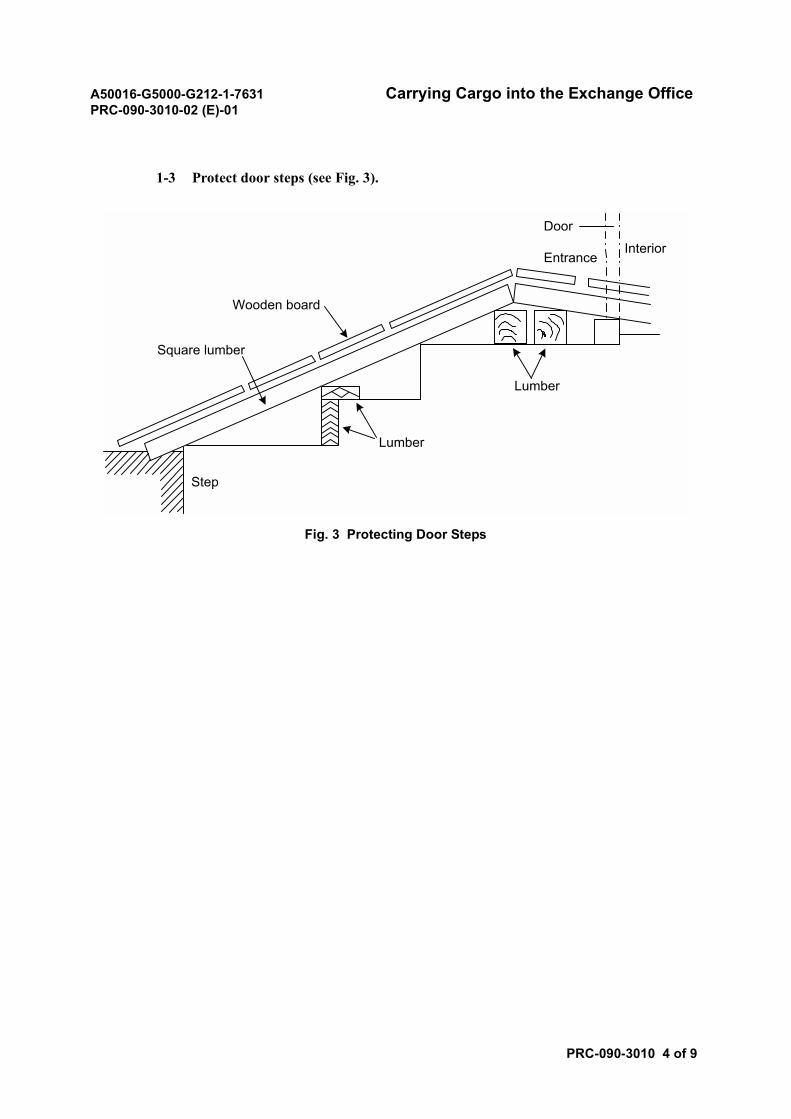
1-3 Protect door steps (see Fig. 3).
Fig. 3 Protecting Door Steps
Wooden board
Door
EntranceInterior
Lumber
Lumber
Square lumber
Step
A50016-G5000-G212-1-7631 Carrying Cargo into the Exchange OfficePRC-090-3010-02 (E)-01
PRC-090-3010 5 of 9
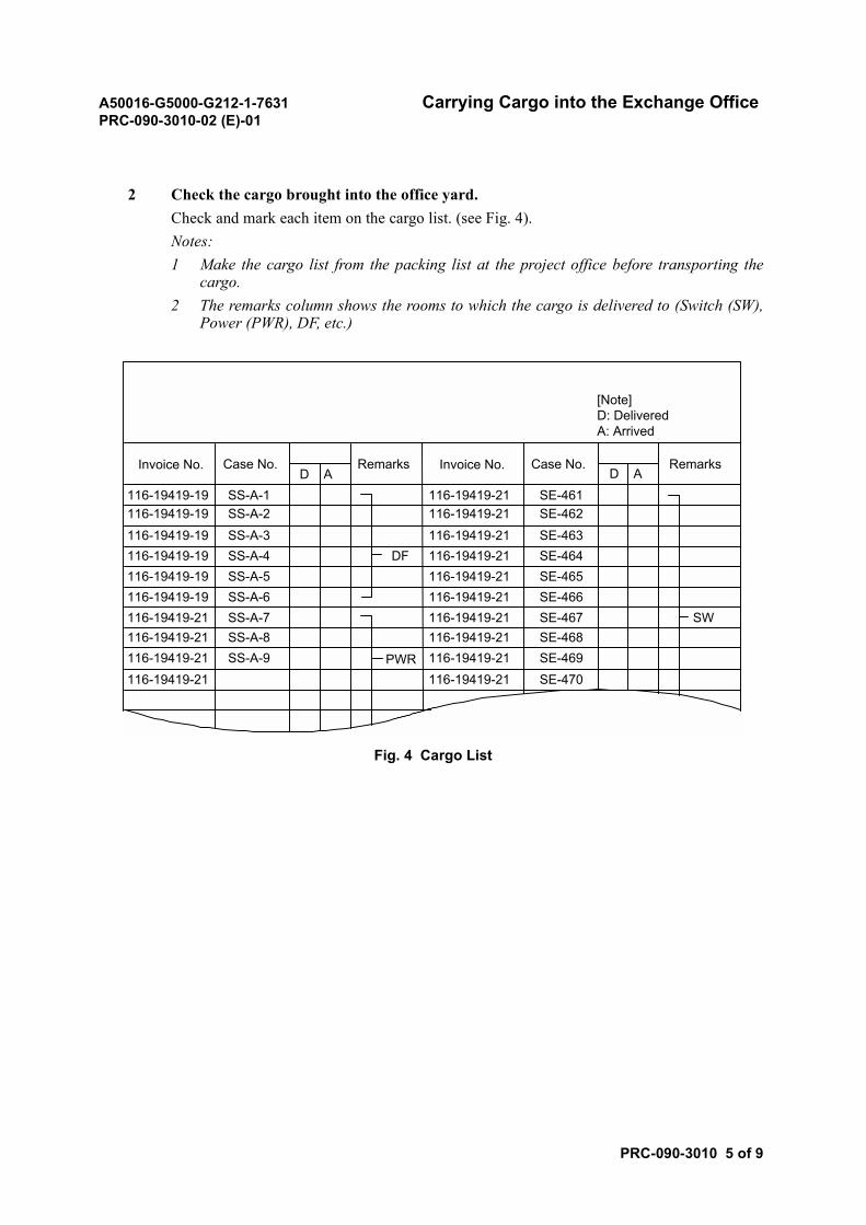
2 Check the cargo brought into the office yard.Check and mark each item on the cargo list. (see Fig. 4).Notes:1 Make the cargo list from the packing list at the project office before transporting the
cargo.2 The remarks column shows the rooms to which the cargo is delivered to (Switch (SW),
Power (PWR), DF, etc.)
Fig. 4 Cargo List
D A D A
SE-462SE-463SE-464SE-465SE-466SE-467SE-468SE-469SE-470
SW
[Note]D: DeliveredA: Arrived
DF
PWR
Invoice No. RemarksCase No. Invoice No. Case No. Remarks
116-19419-19 SS-A-1 116-19419-21 SE-461116-19419-19116-19419-19116-19419-19116-19419-19
116-19419-21116-19419-21116-19419-21
SS-A-2SS-A-3SS-A-4SS-A-5SS-A-6SS-A-7SS-A-8SS-A-9
116-19419-21
116-19419-19
116-19419-21116-19419-21116-19419-21116-19419-21116-19419-21116-19419-21
116-19419-21116-19419-21
116-19419-21
A50016-G5000-G212-1-7631 Carrying Cargo into the Exchange OfficePRC-090-3010-02 (E)-01
PRC-090-3010 6 of 9
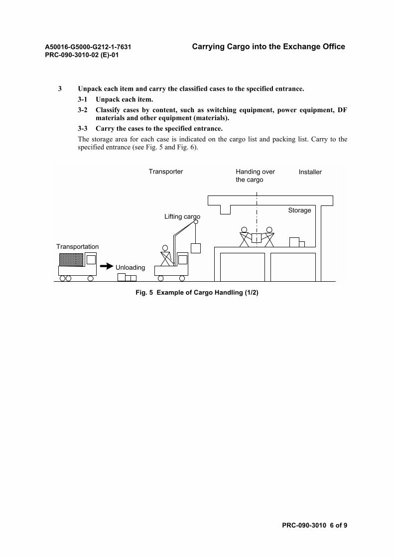
3 Unpack each item and carry the classified cases to the specified entrance.3-1 Unpack each item.3-2 Classify cases by content, such as switching equipment, power equipment, DF
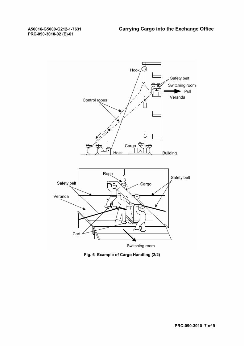
materials and other equipment (materials).3-3 Carry the cases to the specified entrance.The storage area for each case is indicated on the cargo list and packing list. Carry to thespecified entrance (see Fig. 5 and Fig. 6).
Fig. 5 Example of Cargo Handling (1/2)
Transportation
Unloading
Lifting cargo
Handing overthe cargo
InstallerTransporter
Storage
A50016-G5000-G212-1-7631 Carrying Cargo into the Exchange OfficePRC-090-3010-02 (E)-01
PRC-090-3010 7 of 9
Fig. 6 Example of Cargo Handling (2/2)
Hook
Safety belt
Switching roomPull
VerandaControl ropes
Cargo
BuildingHoist
Cargo
Rope
Safety beltSafety belt
Veranda
Cart
Switching room
A50016-G5000-G212-1-7631 Carrying Cargo into the Exchange OfficePRC-090-3010-02 (E)-01
PRC-090-3010 8 of 9
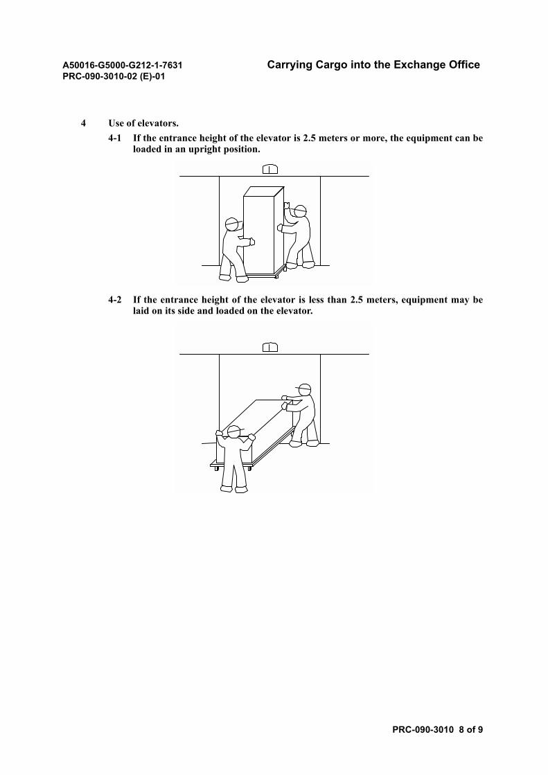
4 Use of elevators.4-1 If the entrance height of the elevator is 2.5 meters or more, the equipment can be
loaded in an upright position.
4-2 If the entrance height of the elevator is less than 2.5 meters, equipment may belaid on its side and loaded on the elevator.
A50016-G5000-G212-1-7631 Carrying Cargo into the Exchange OfficePRC-090-3010-02 (E)-01
PRC-090-3010 9 of 9
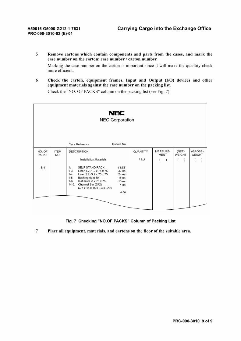
5 Remove cartons which contain components and parts from the cases, and mark thecase number on the carton: case number / carton number.Marking the case number on the carton is important since it will make the quantity checkmore efficient.
6 Check the carton, equipment frames, Input and Output (I/O) devices and otherequipment materials against the case number on the packing list.Check the "NO. OF PACKS" column on the packing list (see Fig. 7).
Fig. 7 Checking "NO.OF PACKS" Column of Packing List
7 Place all equipment, materials, and cartons on the floor of the suitable area.
NEC Corporation
Your Reference Invoice No.
ITEMNO.
DESCRIPTION QUANTITY MEASURE-MENT
(NET)WEIGHT
(GROSS)WEIGHT
NO. OFPACKS
Installation Materials 1 Lot ( ) ( ) ( )
S-1 1. SELF STAND RACK1-3. Liner(1.2) 1.2 x 75 x 751-4. Liner(3.2) 3.2 x 75 x 751-5. Bushing 6t xφ301-6. Instulator 2t x 75 x 751-16. Channel Bar (2F2) C75 x 45 x 15 x 2.3 x 2200
4 ea
1 SET
16 ea16 ea
24 ea32 ea
4 ea
A50016-G5000-G212-1-7631 Quantity CheckPRC-090-3020-02 (E)-01
PRC-090-3020 1 of 2
Quantity Check
1. PROCEDURE
STEP ACTION/REMARKS
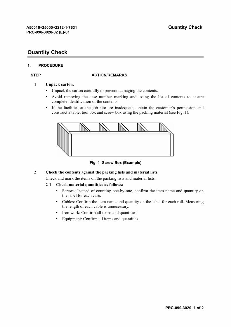
1 Unpack carton.• Unpack the carton carefully to prevent damaging the contents.• Avoid removing the case number marking and losing the list of contents to ensure
complete identification of the contents.• If the facilities at the job site are inadequate, obtain the customer’s permission and
construct a table, tool box and screw box using the packing material (see Fig. 1).
Fig. 1 Screw Box (Example)
2 Check the contents against the packing lists and material lists.Check and mark the items on the packing lists and material lists.2-1 Check material quantities as follows:
• Screws: Instead of counting one-by-one, confirm the item name and quantity onthe label for each case.
• Cables: Confirm the item name and quantity on the label for each roll. Measuringthe length of each cable is unnecessary.
• Iron work: Confirm all items and quantities.• Equipment: Confirm all items and quantities.
A50016-G5000-G212-1-7631 Quantity CheckPRC-090-3020-02 (E)-01
PRC-090-3020 2 of 2
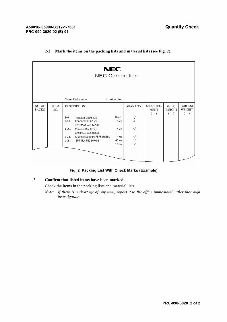
2-2 Mark the items on the packing lists and material lists (see Fig. 2).
Fig. 2 Packing List With Check Marks (Example)
3 Confirm that listed items have been marked.Check the items in the packing lists and material lists.Note: If there is a shortage of any item, report it to the office immediately after thorough
investigation.
NEC Corporation
Your Reference Invoice No.
NO. OFPACKS
ITEMNO.
1-6.1-16.
DESCRIPTION
1-20.
1-23.1-24.
Insulator 2tx75x75Channel Bar (2F2)C75x45x15x2.3x2200Channel Bar (2F2)C75x45x15x2.3x898Channel Support FB75x6x580SPT Nut FB38x9x62
16 ea4 ea
4 ea
4 ea40 ea18 ea
-4
QUANTITY MEASURE-MENT( )
(NET)WEIGHT
( )
(GROSS)WEIGHT
( )

A50016-G5000-G212-1-7631ND-57268-706 (E)-01
SECTION 5WORK IN SWITCHING ROOM
A50016-G5000-G212-1-7631 Installing Equipment FramePRC-090-4010-03 (E)-03
PRC-090-4010 1 of 22
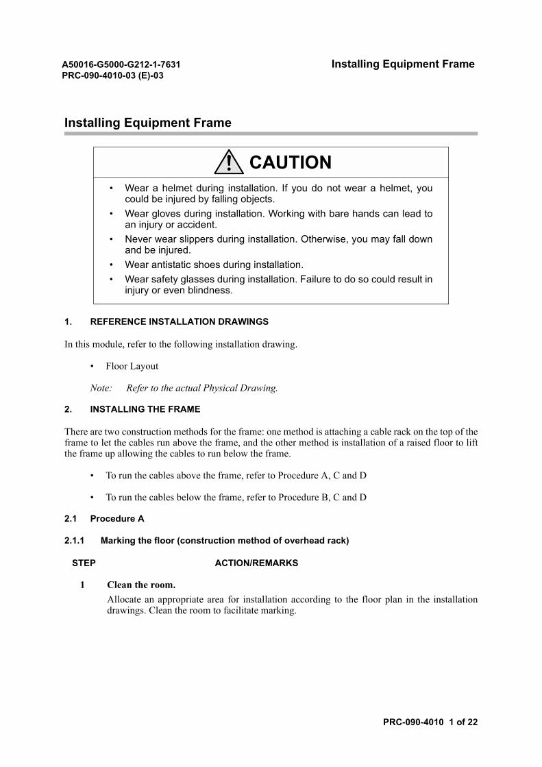
Installing Equipment Frame
1. REFERENCE INSTALLATION DRAWINGS
In this module, refer to the following installation drawing.
• Floor Layout
Note: Refer to the actual Physical Drawing.
2. INSTALLING THE FRAME
There are two construction methods for the frame: one method is attaching a cable rack on the top of theframe to let the cables run above the frame, and the other method is installation of a raised floor to liftthe frame up allowing the cables to run below the frame.
• To run the cables above the frame, refer to Procedure A, C and D
• To run the cables below the frame, refer to Procedure B, C and D
2.1 Procedure A
2.1.1 Marking the floor (construction method of overhead rack)
STEP ACTION/REMARKS
1 Clean the room.Allocate an appropriate area for installation according to the floor plan in the installationdrawings. Clean the room to facilitate marking.
CAUTION• Wear a helmet during installation. If you do not wear a helmet, you
could be injured by falling objects.• Wear gloves during installation. Working with bare hands can lead to
an injury or accident.• Never wear slippers during installation. Otherwise, you may fall down
and be injured.• Wear antistatic shoes during installation.• Wear safety glasses during installation. Failure to do so could result in
injury or even blindness.
A50016-G5000-G212-1-7631 Installing Equipment FramePRC-090-4010-03 (E)-03
PRC-090-4010 2 of 22
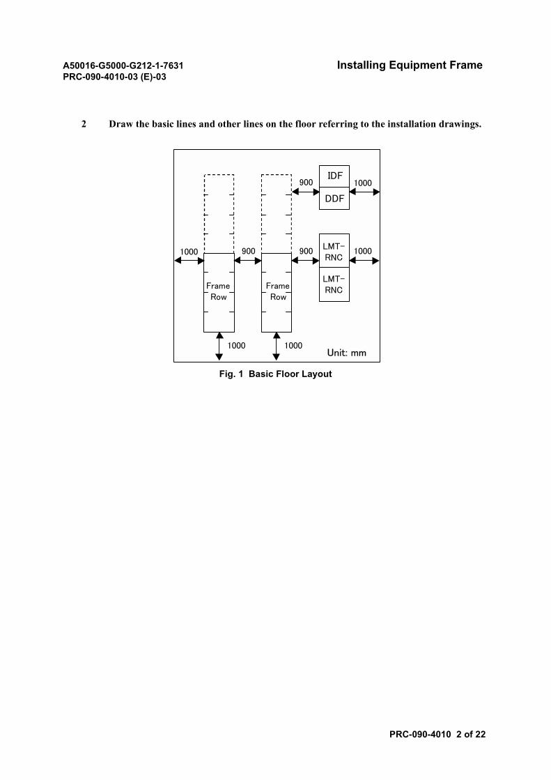
2 Draw the basic lines and other lines on the floor referring to the installation drawings.
Fig. 1 Basic Floor Layout
FrameRow
FrameRow
LMT-RNC
LMT-RNC
IDF
DDF
1000 1000
1000
10001000
900900
900
Unit: mm
A50016-G5000-G212-1-7631 Installing Equipment FramePRC-090-4010-03 (E)-03
PRC-090-4010 3 of 22
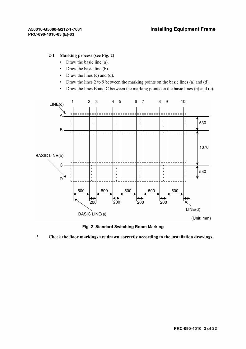
2-1 Marking process (see Fig. 2)• Draw the basic line (a).• Draw the basic line (b).• Draw the lines (c) and (d).• Draw the lines 2 to 9 between the marking points on the basic lines (a) and (d).• Draw the lines B and C between the marking points on the basic lines (b) and (c).
Fig. 2 Standard Switching Room Marking
3 Check the floor markings are drawn correctly according to the installation drawings.
500 500 500 500 500
200 200 200 200
530
1070
530
1 32 4 5 6 7 8 9 10LINE(c)
A
B
C
D
BASIC LINE(b)
BASIC LINE(a)LINE(d)
(Unit: mm)
A50016-G5000-G212-1-7631 Installing Equipment FramePRC-090-4010-03 (E)-03
PRC-090-4010 4 of 22
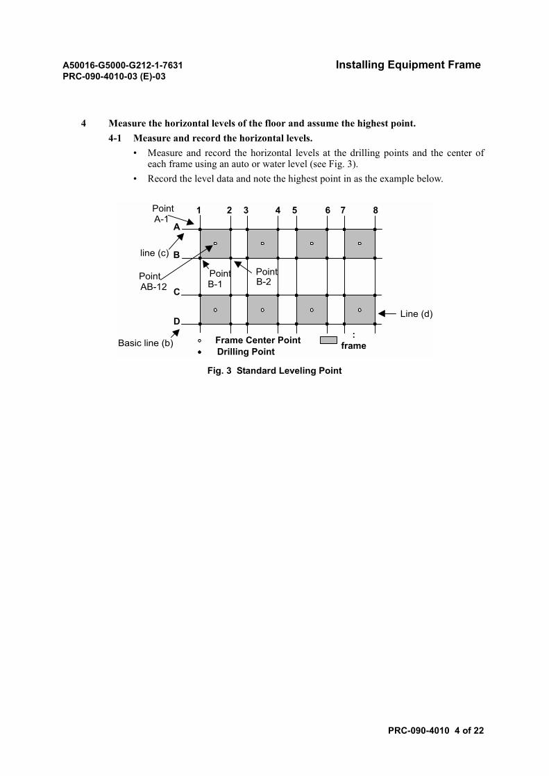
4 Measure the horizontal levels of the floor and assume the highest point.4-1 Measure and record the horizontal levels.
• Measure and record the horizontal levels at the drilling points and the center ofeach frame using an auto or water level (see Fig. 3).
• Record the level data and note the highest point in as the example below.
Fig. 3 Standard Leveling Point
Frame Center Point :frameDrilling Point
A
B
C
D
Basic line (b)
line (c)
1 2 3 4 5 6
Line (d)
PointB-2
PointA-1
PointAB-12
PointB-1
7 8
A50016-G5000-G212-1-7631 Installing Equipment FramePRC-090-4010-03 (E)-03
PRC-090-4010 5 of 22
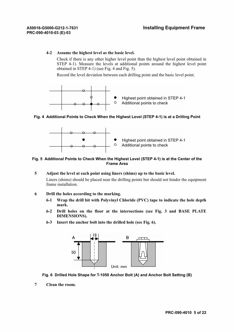
4-2 Assume the highest level as the basic level.Check if there is any other higher level point than the highest level point obtained inSTEP 4-1). Measure the levels at additional points around the highest level pointobtained in STEP 4-1) (see Fig. 4 and Fig. 5).Record the level deviation between each drilling point and the basic level point.
Fig. 4 Additional Points to Check When the Highest Level (STEP 4-1) is at a Drilling Point
Fig. 5 Additional Points to Check When the Highest Level (STEP 4-1) is at the Center of the Frame Area
5 Adjust the level at each point using liners (shims) up to the basic level.Liners (shims) should be placed near the drilling points but should not hinder the equipmentframe installation.
6 Drill the holes according to the marking.6-1 Wrap the drill bit with Polyvinyl Chloride (PVC) tape to indicate the hole depth
mark.6-2 Drill holes on the floor at the intersections (see Fig. 3 and BASE PLATE
DIMENSIONS).6-3 Insert the anchor bolt into the drilled hole (see Fig. 6).
Fig. 6 Drilled Hole Shape for T-1050 Anchor Bolt (A) and Anchor Bolt Setting (B)
7 Clean the room.
Highest point obtained in STEP 4-1Additional points to check
Highest point obtained in STEP 4-1Additional points to check
Unit: mm
18A B
50
A50016-G5000-G212-1-7631 Installing Equipment FramePRC-090-4010-03 (E)-03
PRC-090-4010 6 of 22
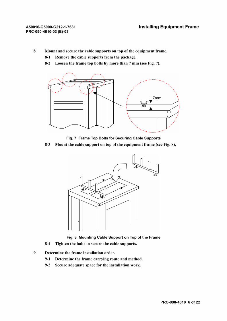
8 Mount and secure the cable supports on top of the equipment frame.8-1 Remove the cable supports from the package.8-2 Loosen the frame top bolts by more than 7 mm (see Fig. 7).
Fig. 7 Frame Top Bolts for Securing Cable Supports8-3 Mount the cable support on top of the equipment frame (see Fig. 8).
Fig. 8 Mounting Cable Support on Top of the Frame8-4 Tighten the bolts to secure the cable supports.
9 Determine the frame installation order.9-1 Determine the frame carrying route and method.9-2 Secure adequate space for the installation work.
7mm
A50016-G5000-G212-1-7631 Installing Equipment FramePRC-090-4010-03 (E)-03
PRC-090-4010 7 of 22
10 Erect the equipment frame at the specified position.10-1 Carry the frame to the location specified for erection.10-2 Move the frame on a cart to the installation position.10-3 Finely adjust the frame position.
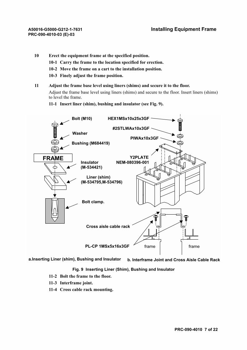
11 Adjust the frame base level using liners (shims) and secure it to the floor.Adjust the frame base level using liners (shims) and secure to the floor. Insert liners (shims)to level the frame.11-1 Insert liner (shim), bushing and insulator (see Fig. 9).
Fig. 9 Inserting Liner (Shim), Bushing and Insulator11-2 Bolt the frame to the floor.11-3 Interframe joint.11-4 Cross cable rack mounting.
Bolt (M10) HEX1MSx10x25x3GF
#2STLWAx10x3GFWasher
PIWAx10x3GFBushing (M684419)
Y2PLATEInsulator NEM-080396-001(M-534421)
Liner (shim)(M-534795,M-534796)
Bolt clamp.
Cross aisle cable rack
PL-CP 1MSx5x16x3GF frame frame
a.Inserting Liner (shim), Bushing and Insulator b. Interframe Joint and Cross Aisle Cable Rack
FRAME
A50016-G5000-G212-1-7631 Installing Equipment FramePRC-090-4010-03 (E)-03
PRC-090-4010 8 of 22
2.2 Procedure B
2.2.1 Marking the floor (construction method of frame base)
STEP ACTION/REMARKS
1 Clean the room.Allocate an appropriate area for installation according to the floor plan in the installationdrawings. Clean the room to facilitate marking.
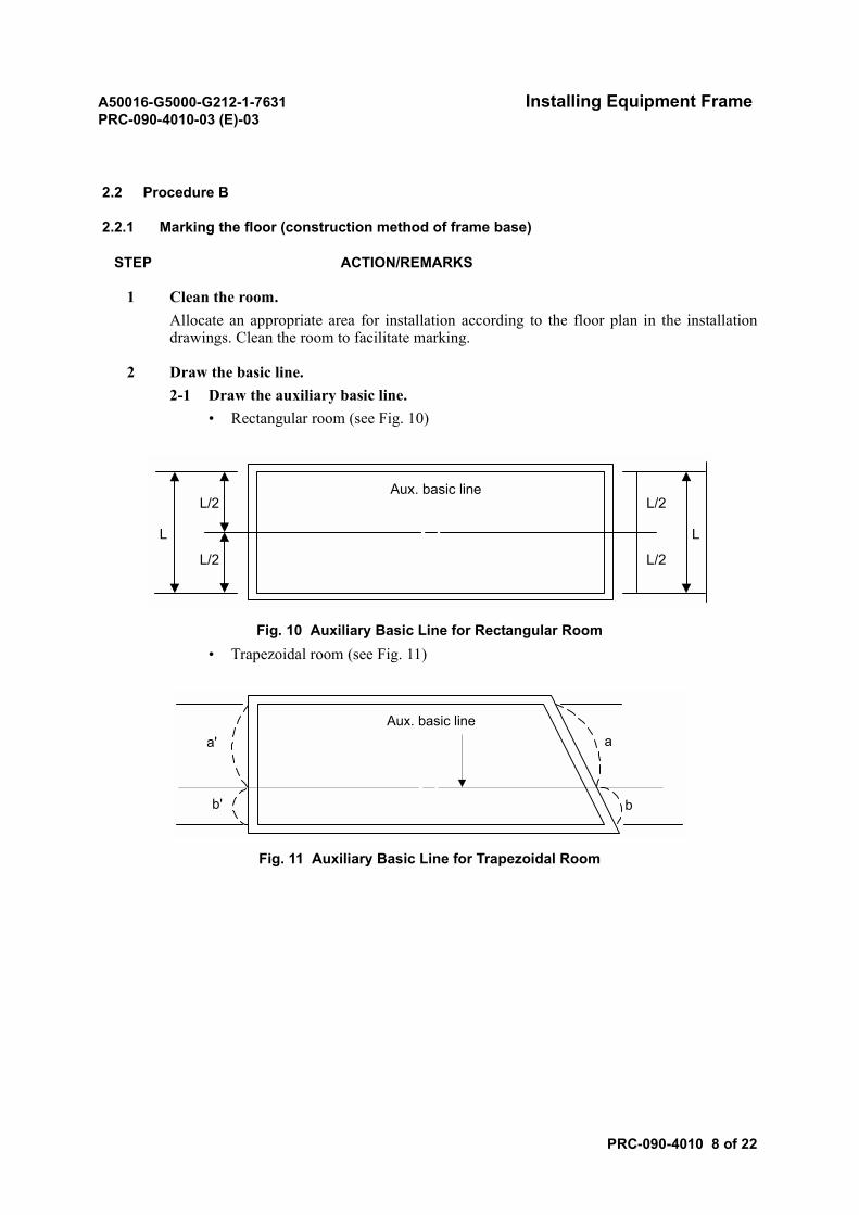
2 Draw the basic line.2-1 Draw the auxiliary basic line.
• Rectangular room (see Fig. 10)
Fig. 10 Auxiliary Basic Line for Rectangular Room• Trapezoidal room (see Fig. 11)
Fig. 11 Auxiliary Basic Line for Trapezoidal Room
Aux. basic lineL/2
L/2
L
L/2
L/2
L
a'
b' b
aAux. basic line
A50016-G5000-G212-1-7631 Installing Equipment FramePRC-090-4010-03 (E)-03
PRC-090-4010 9 of 22
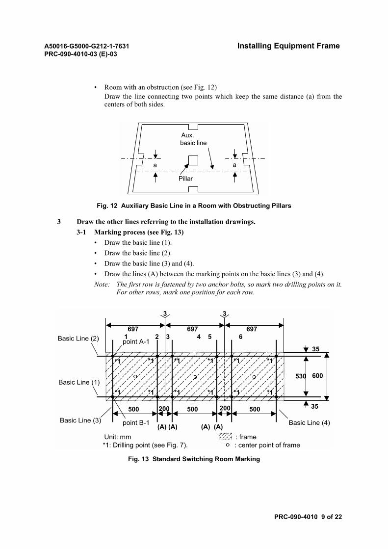
• Room with an obstruction (see Fig. 12)Draw the line connecting two points which keep the same distance (a) from thecenters of both sides.
Fig. 12 Auxiliary Basic Line in a Room with Obstructing Pillars
3 Draw the other lines referring to the installation drawings.3-1 Marking process (see Fig. 13)
• Draw the basic line (1).• Draw the basic line (2).• Draw the basic line (3) and (4).• Draw the lines (A) between the marking points on the basic lines (3) and (4).Note: The first row is fastened by two anchor bolts, so mark two drilling points on it.
For other rows, mark one position for each row.
Fig. 13 Standard Switching Room Marking
aa
Pillar
Aux.basic line
Unit: mm : frame*1: Drilling point (see Fig. 7). : center point of frame
1 2 3 4 5 6
*1 *1 *1 *1 *1 *1
*1 *1 *1*1 *1 *1
500 500 500200 200
697 697 697
point A-1
point B-1
530 600
35
35
(A) (A) (A) (A)
Basic Line (1)
Basic Line (3)
Basic Line (2)
Basic Line (4)
3 3
A50016-G5000-G212-1-7631 Installing Equipment FramePRC-090-4010-03 (E)-03
PRC-090-4010 10 of 22
3-2 Drilling holes (see Fig. 7)• Drill holes on the floor at intersections.• Insert the anchor bolt into the drilled hole.
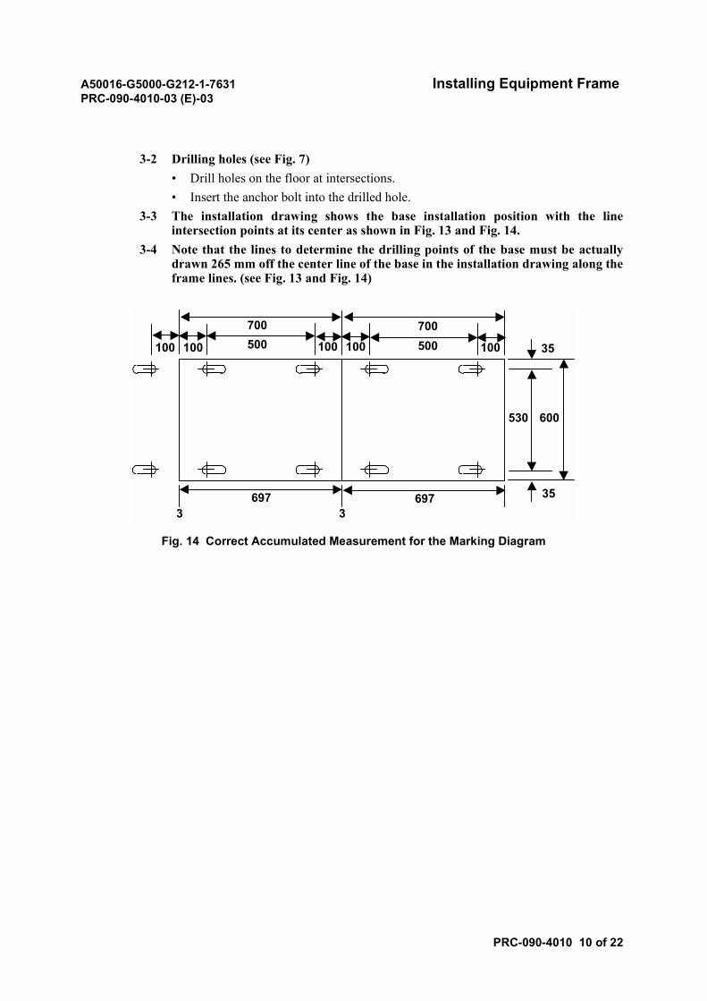
3-3 The installation drawing shows the base installation position with the lineintersection points at its center as shown in Fig. 13 and Fig. 14.
3-4 Note that the lines to determine the drilling points of the base must be actuallydrawn 265 mm off the center line of the base in the installation drawing along theframe lines. (see Fig. 13 and Fig. 14)
Fig. 14 Correct Accumulated Measurement for the Marking Diagram
697 6973 3
500 500700700
100100 100100 100
530 600
35
35
A50016-G5000-G212-1-7631 Installing Equipment FramePRC-090-4010-03 (E)-03
PRC-090-4010 11 of 22
2.2.2 Installing power cable supports
Procedure
STEP ACTION/REMARKS
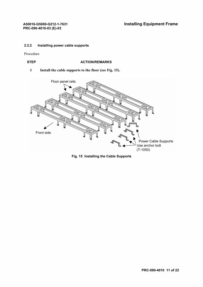
1 Install the cable supports to the floor (see Fig. 15).
Fig. 15 Installing the Cable Supports
Floor panel rails
Front side
Power Cable SupportsUse anchor bolt(T-1050)
A50016-G5000-G212-1-7631 Installing Equipment FramePRC-090-4010-03 (E)-03
PRC-090-4010 12 of 22
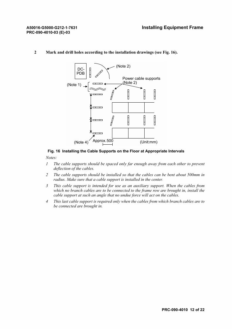
2 Mark and drill holes according to the installation drawings (see Fig. 16).
Fig. 16 Installing the Cable Supports on the Floor at Appropriate IntervalsNotes:1 The cable supports should be spaced only far enough away from each other to prevent
deflection of the cables.2 The cable supports should be installed so that the cables can be bent about 500mm in
radius. Make sure that a cable support is installed in the center.3 This cable support is intended for use as an auxiliary support. When the cables from
which no branch cables are to be connected to the frame row are brought in, install thecable support at such an angle that no undue force will act on the cables.
4 This last cable support is required only when the cables from which branch cables are tobe connected are brought in.
DC-PDB
(Note 2)
(Note 1)Power cable supports(Note 2)
(Note 4) Approx.500 (Unit:mm)
A50016-G5000-G212-1-7631 Installing Equipment FramePRC-090-4010-03 (E)-03
PRC-090-4010 13 of 22
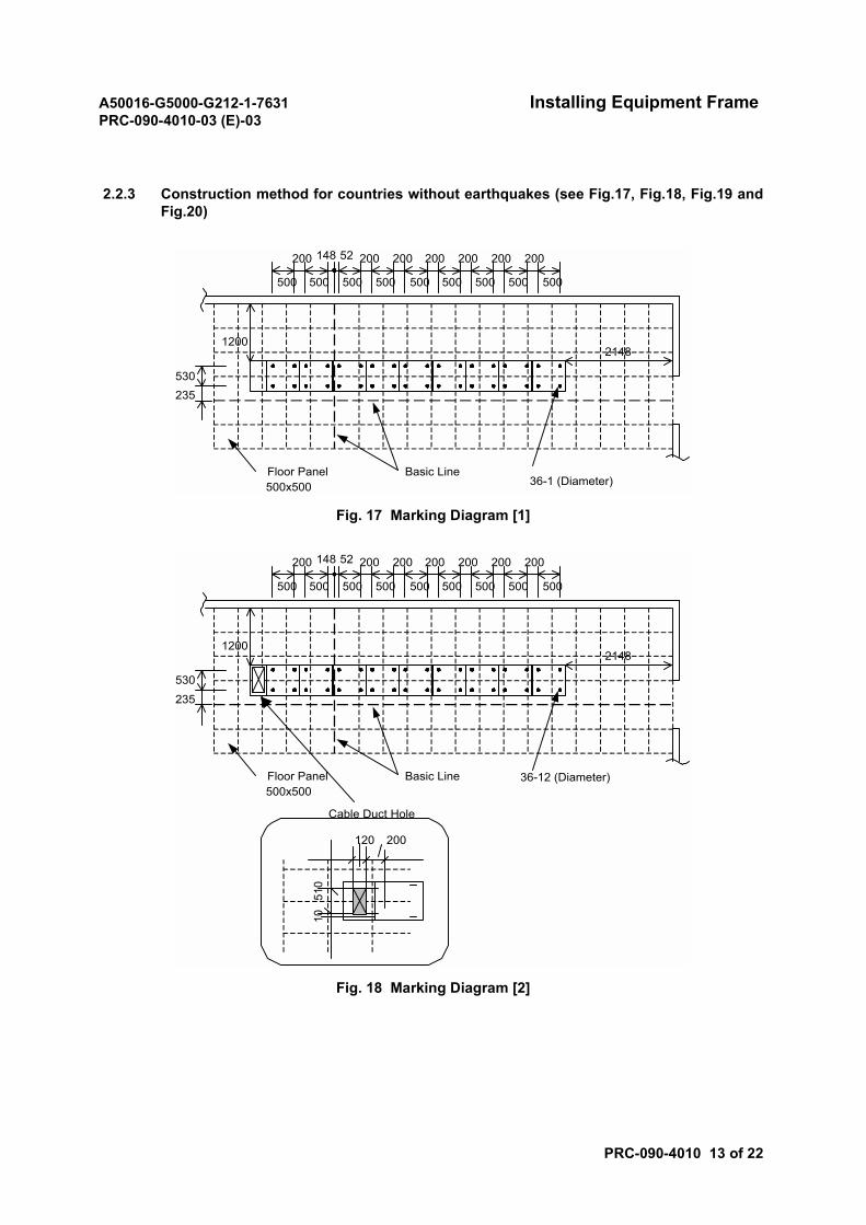
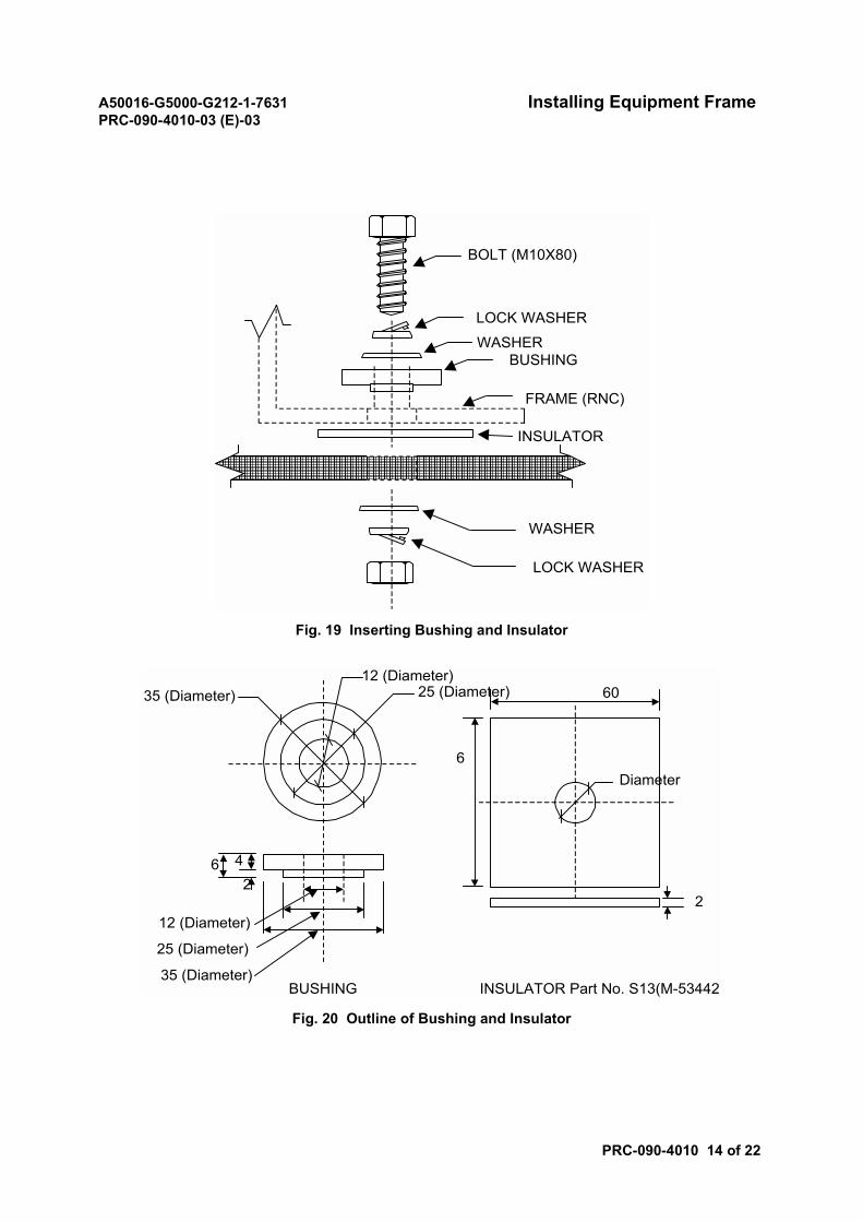
2.2.3 Construction method for countries without earthquakes (see Fig.17, Fig.18, Fig.19 andFig.20)
Fig. 17 Marking Diagram [1]
Fig. 18 Marking Diagram [2]
500 500 500 500 500 500 500 500 500
200 200 200 200 200 200 200148 52
530235
12002148
Floor Panel500x500
Basic Line36-1 (Diameter)
120 200
1051
0
Cable Duct Hole
500 500 500 500 500 500 500 500 500
200 200 200 200 200 200 200148 52
530
235
12002148
Floor Panel500x500
Basic Line 36-12 (Diameter)
A50016-G5000-G212-1-7631 Installing Equipment FramePRC-090-4010-03 (E)-03
PRC-090-4010 14 of 22
Fig. 19 Inserting Bushing and Insulator
Fig. 20 Outline of Bushing and Insulator
WASHER
LOCK WASHER
INSULATOR
BOLT (M10X80)
LOCK WASHER
WASHERBUSHING
FRAME (RNC)
BUSHING INSULATOR Part No. S13(M-53442
35 (Diameter)12 (Diameter)
25 (Diameter)
42
6
60
6Diameter
212 (Diameter)
25 (Diameter)
35 (Diameter)
A50016-G5000-G212-1-7631 Installing Equipment FramePRC-090-4010-03 (E)-03
PRC-090-4010 15 of 22
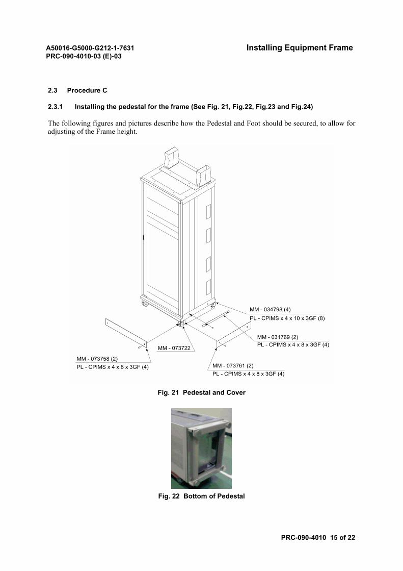
2.3 Procedure C
2.3.1 Installing the pedestal for the frame (See Fig. 21, Fig.22, Fig.23 and Fig.24)
The following figures and pictures describe how the Pedestal and Foot should be secured, to allow foradjusting of the Frame height.
Fig. 21 Pedestal and Cover
Fig. 22 Bottom of Pedestal
MM - 073758 (2)MM - 073761 (2)
MM - 073722
PL - CPIMS x 4 x 8 x 3GF (4)PL - CPIMS x 4 x 8 x 3GF (4)
MM - 031769 (2)PL - CPIMS x 4 x 8 x 3GF (4)
MM - 034798 (4)PL - CPIMS x 4 x 10 x 3GF (8)
A50016-G5000-G212-1-7631 Installing Equipment FramePRC-090-4010-03 (E)-03
PRC-090-4010 16 of 22
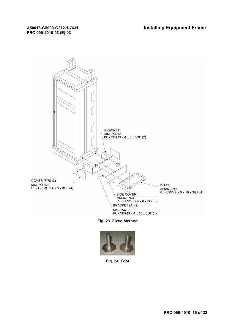
Fig. 23 Fixed Method
Fig. 24 Foot
COVER (F/R) (2)MM-073762PL - CPIMS x 4 x 8 x 3GF (4)
BRACKETMM-073764PL - CPIMS x 4 x 8 x 3GF (2)
PLATEMM-070797PL - CPIMS x 5 x 16 x 3GF (4)SIDE COVER
MM-073763PL - CPIMS x 4 x 8 x 3GF (2)
BRACKET (A) (2)MM-034798PL - CPIMS x 4 x 10 x 3GF (4)
A50016-G5000-G212-1-7631 Installing Equipment FramePRC-090-4010-03 (E)-03
PRC-090-4010 17 of 22
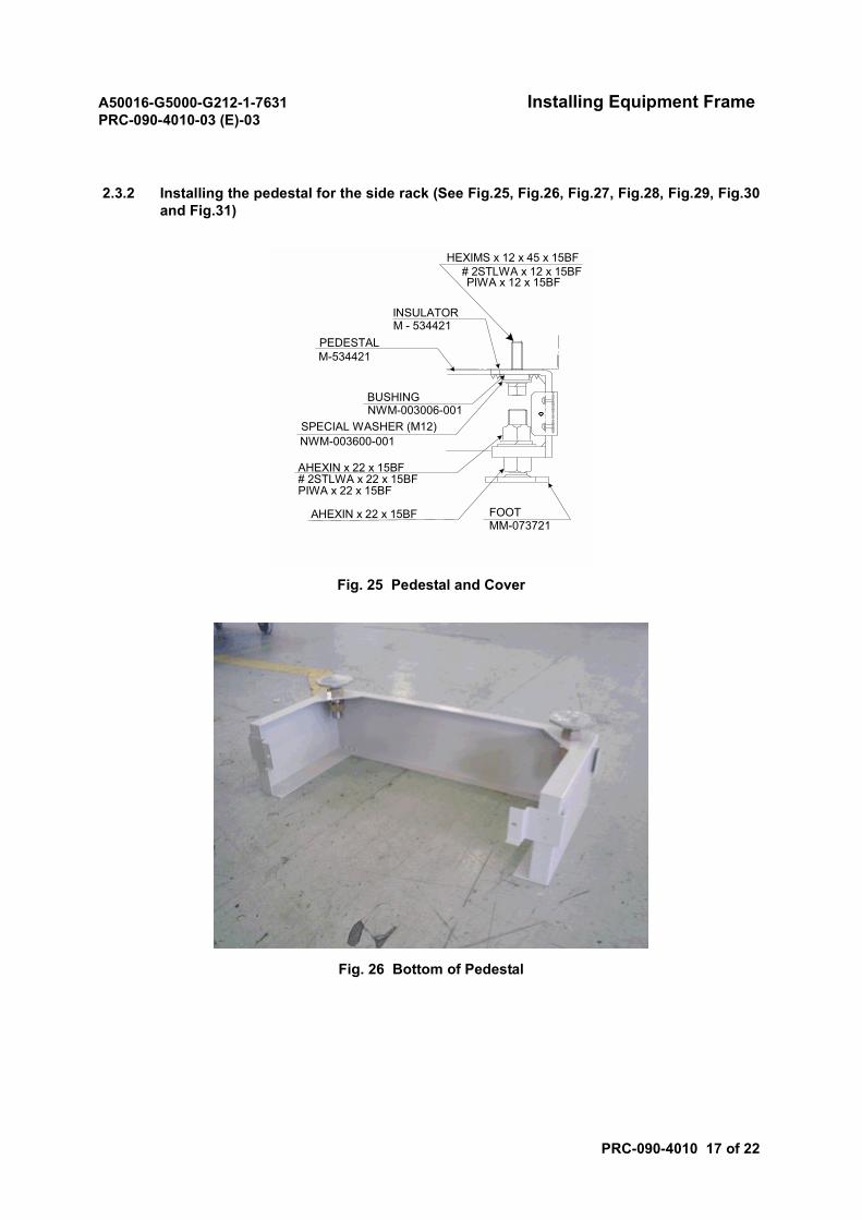
2.3.2 Installing the pedestal for the side rack (See Fig.25, Fig.26, Fig.27, Fig.28, Fig.29, Fig.30and Fig.31)
Fig. 25 Pedestal and Cover
Fig. 26 Bottom of Pedestal
INSULATORM - 534421
HEXIMS x 12 x 45 x 15BF# 2STLWA x 12 x 15BFPIWA x 12 x 15BF
AHEXIN x 22 x 15BF
AHEXIN x 22 x 15BF# 2STLWA x 22 x 15BFPIWA x 22 x 15BF
MM-073721FOOT
NWM-003600-001SPECIAL WASHER (M12)
BUSHINGNWM-003006-001
PEDESTALM-534421
A50016-G5000-G212-1-7631 Installing Equipment FramePRC-090-4010-03 (E)-03
PRC-090-4010 18 of 22
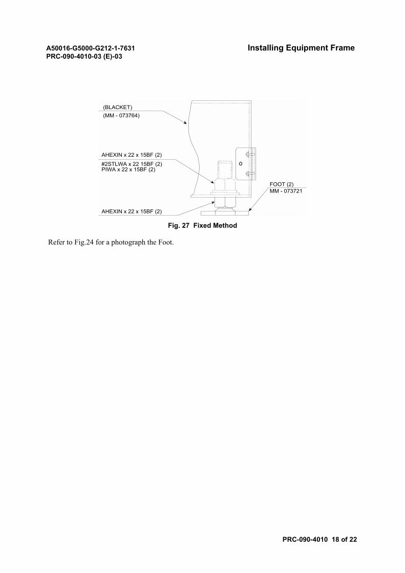
Fig. 27 Fixed Method
Refer to Fig.24 for a photograph the Foot.
(BLACKET) (MM - 073764)
AHEXIN x 22 x 15BF (2)
AHEXIN x 22 x 15BF (2)
FOOT (2)MM - 073721
#2STLWA x 22 15BF (2)PIWA x 22 x 15BF (2)
A50016-G5000-G212-1-7631 Installing Equipment FramePRC-090-4010-03 (E)-03
PRC-090-4010 19 of 22
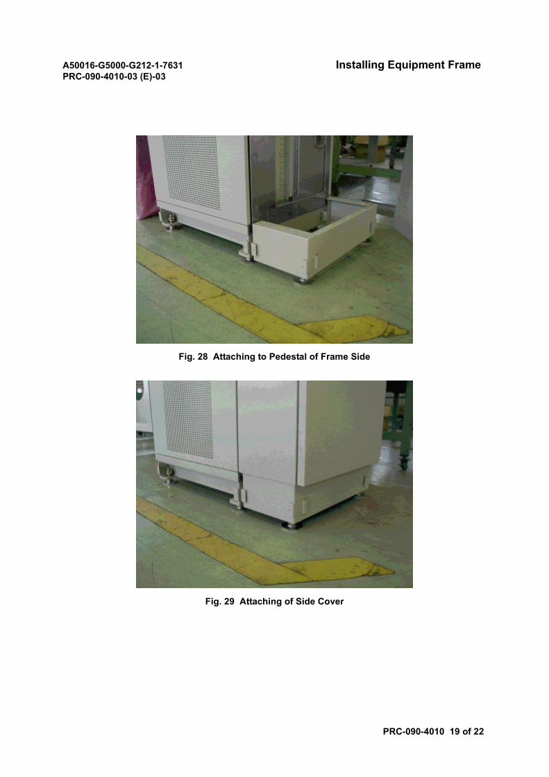
Fig. 28 Attaching to Pedestal of Frame Side
Fig. 29 Attaching of Side Cover
A50016-G5000-G212-1-7631 Installing Equipment FramePRC-090-4010-03 (E)-03
PRC-090-4010 20 of 22
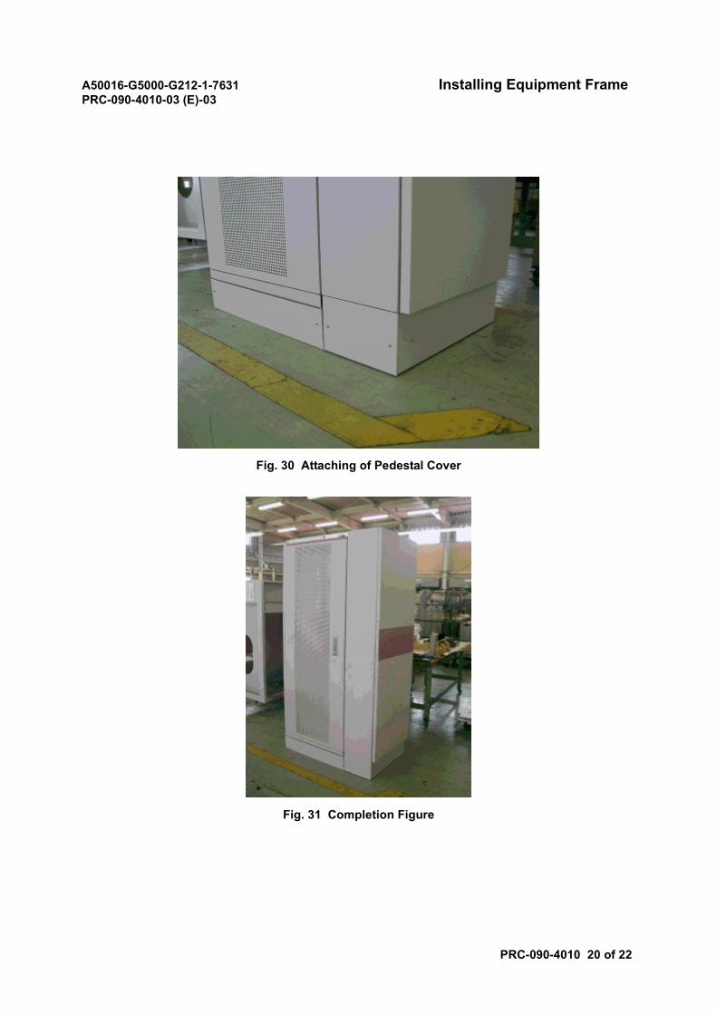
Fig. 30 Attaching of Pedestal Cover
Fig. 31 Completion Figure
A50016-G5000-G212-1-7631 Installing Equipment FramePRC-090-4010-03 (E)-03
PRC-090-4010 21 of 22
2.4 Procedure D
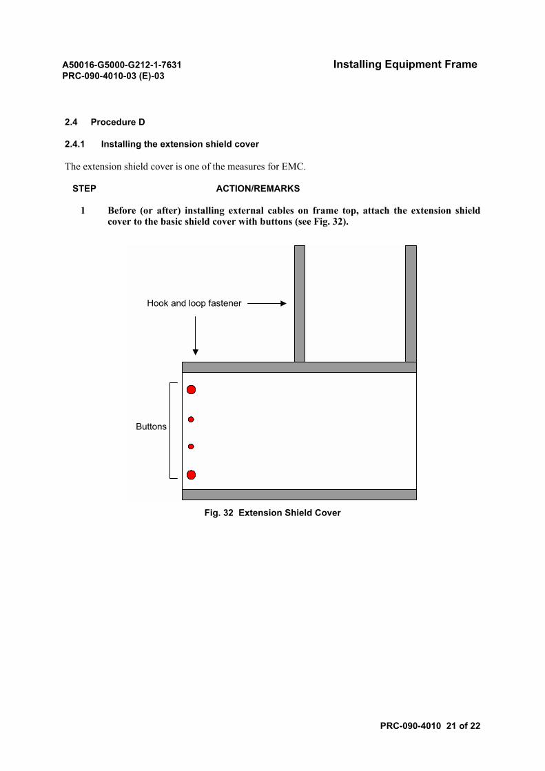
2.4.1 Installing the extension shield cover
The extension shield cover is one of the measures for EMC.
STEP ACTION/REMARKS
1 Before (or after) installing external cables on frame top, attach the extension shieldcover to the basic shield cover with buttons (see Fig. 32).
Fig. 32 Extension Shield Cover
Buttons
Hook and loop fastener
A50016-G5000-G212-1-7631 Installing Equipment FramePRC-090-4010-03 (E)-03
PRC-090-4010 22 of 22
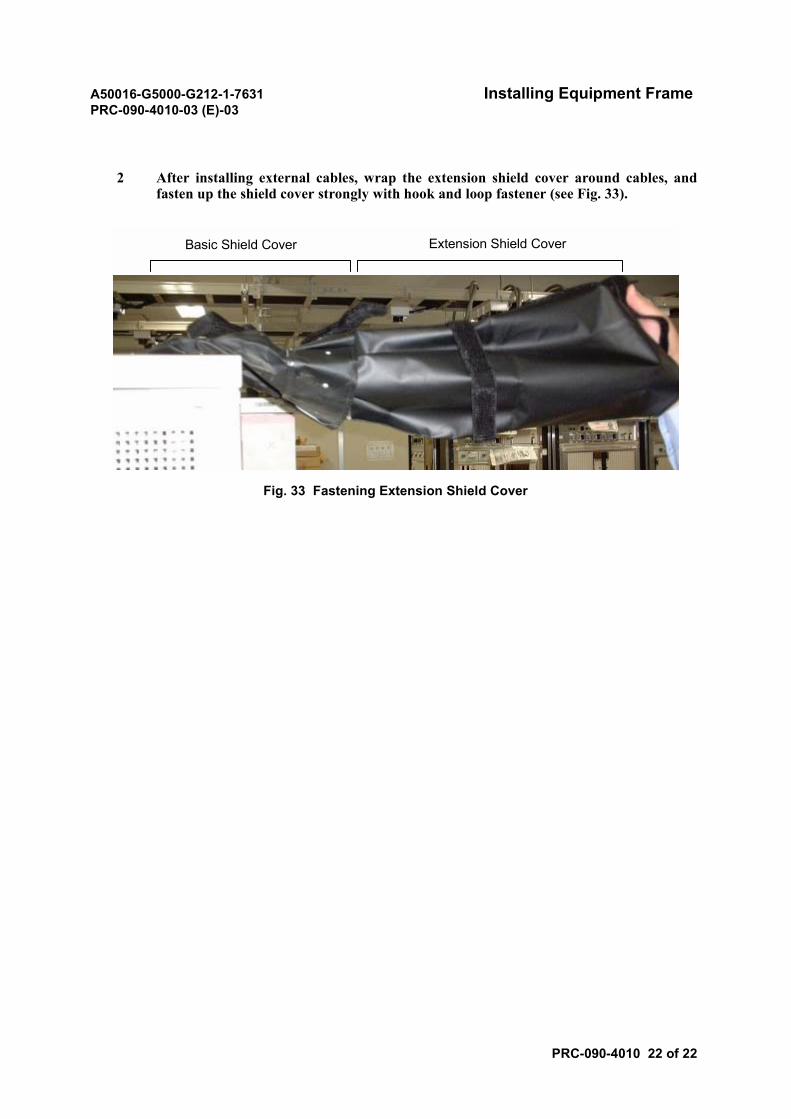
2 After installing external cables, wrap the extension shield cover around cables, andfasten up the shield cover strongly with hook and loop fastener (see Fig. 33).
Fig. 33 Fastening Extension Shield Cover
Basic Shield Cover Extension Shield Cover
A50016-G5000-G212-1-7631 Installing DC-PDBPRC-090-4020-02 (E)-01
PRC-090-4020 1 of 2
Installing DC-PDB
1. REFERENCE INSTALLATION DRAWINGS
In this module, refer to the following installation drawing.
• Floor Layout
Note: Refer to the actual Physical Drawing.
2. PROCEDURE
STEP ACTION/REMARKS
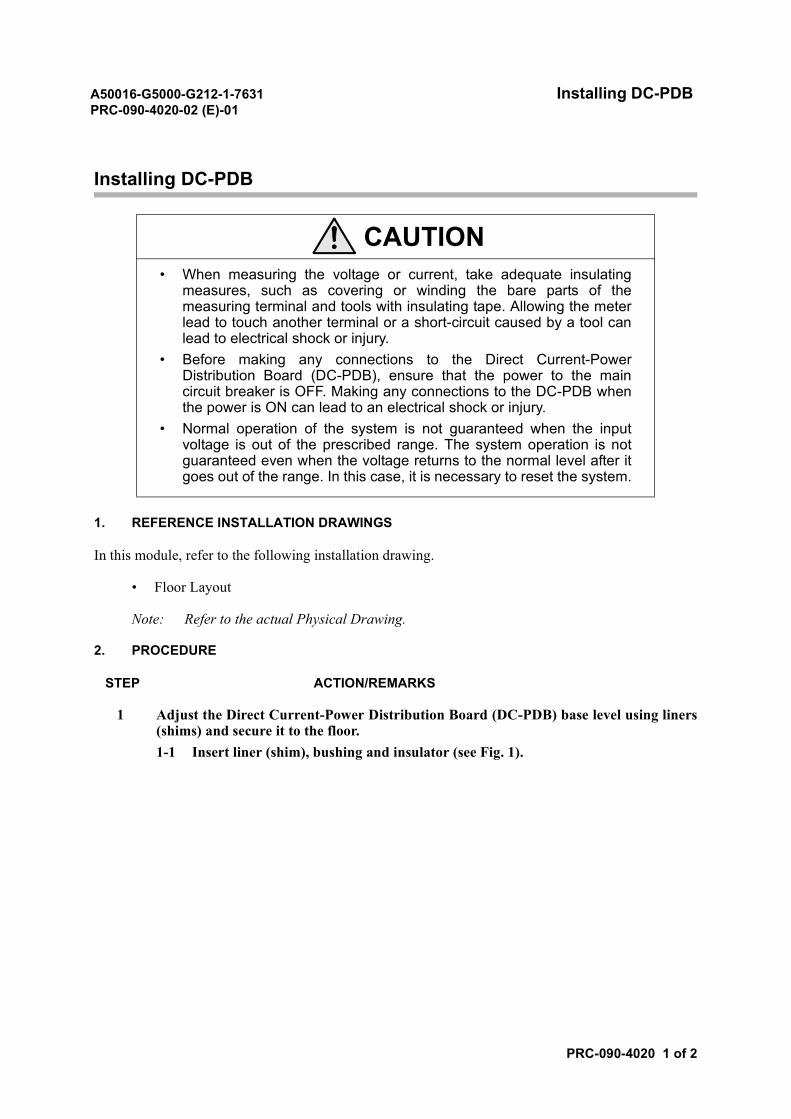
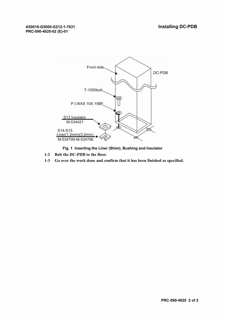
1 Adjust the Direct Current-Power Distribution Board (DC-PDB) base level using liners(shims) and secure it to the floor.1-1 Insert liner (shim), bushing and insulator (see Fig. 1).
CAUTION• When measuring the voltage or current, take adequate insulating
measures, such as covering or winding the bare parts of themeasuring terminal and tools with insulating tape. Allowing the meterlead to touch another terminal or a short-circuit caused by a tool canlead to electrical shock or injury.
• Before making any connections to the Direct Current-PowerDistribution Board (DC-PDB), ensure that the power to the maincircuit breaker is OFF. Making any connections to the DC-PDB whenthe power is ON can lead to an electrical shock or injury.
• Normal operation of the system is not guaranteed when the inputvoltage is out of the prescribed range. The system operation is notguaranteed even when the voltage returns to the normal level after itgoes out of the range. In this case, it is necessary to reset the system.
A50016-G5000-G212-1-7631 Installing DC-PDBPRC-090-4020-02 (E)-01
PRC-090-4020 2 of 2
Fig. 1 Inserting the Liner (Shim), Bushing and Insulator1-2 Bolt the DC-PDB to the floor.1-3 Go over the work done and confirm that it has been finished as specified.
Front side
T-1050bolt
P.I.WAX 10X 15BF
S13 InsulatorM-534421
DC-PDB
S14-S15Liner(1.2mm)(3.2mm)M-534795-M-534796
A50016-G5000-G212-1-7631 Installing AALP and VALPPRC-090-4030-02 (E)-01
PRC-090-4030 1 of 4
Installing AALP and VALP
1. REFERENCE INSTALLATION DRAWINGS
In this module, refer to the following installation drawing.
• Floor Layout
Note: Refer to the actual Physical Drawing.
2. PROCEDURE
STEP ACTION/REMARKS
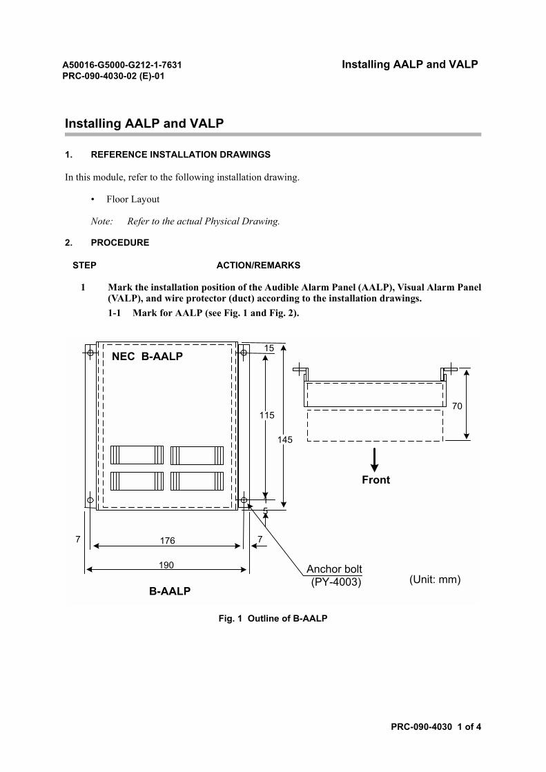
1 Mark the installation position of the Audible Alarm Panel (AALP), Visual Alarm Panel(VALP), and wire protector (duct) according to the installation drawings.1-1 Mark for AALP (see Fig. 1 and Fig. 2).
Fig. 1 Outline of B-AALP
NEC B-AALP
7
115
145
15
15
176
190
7
70
Front
Anchor bolt(PY-4003)
B-AALP(Unit: mm)
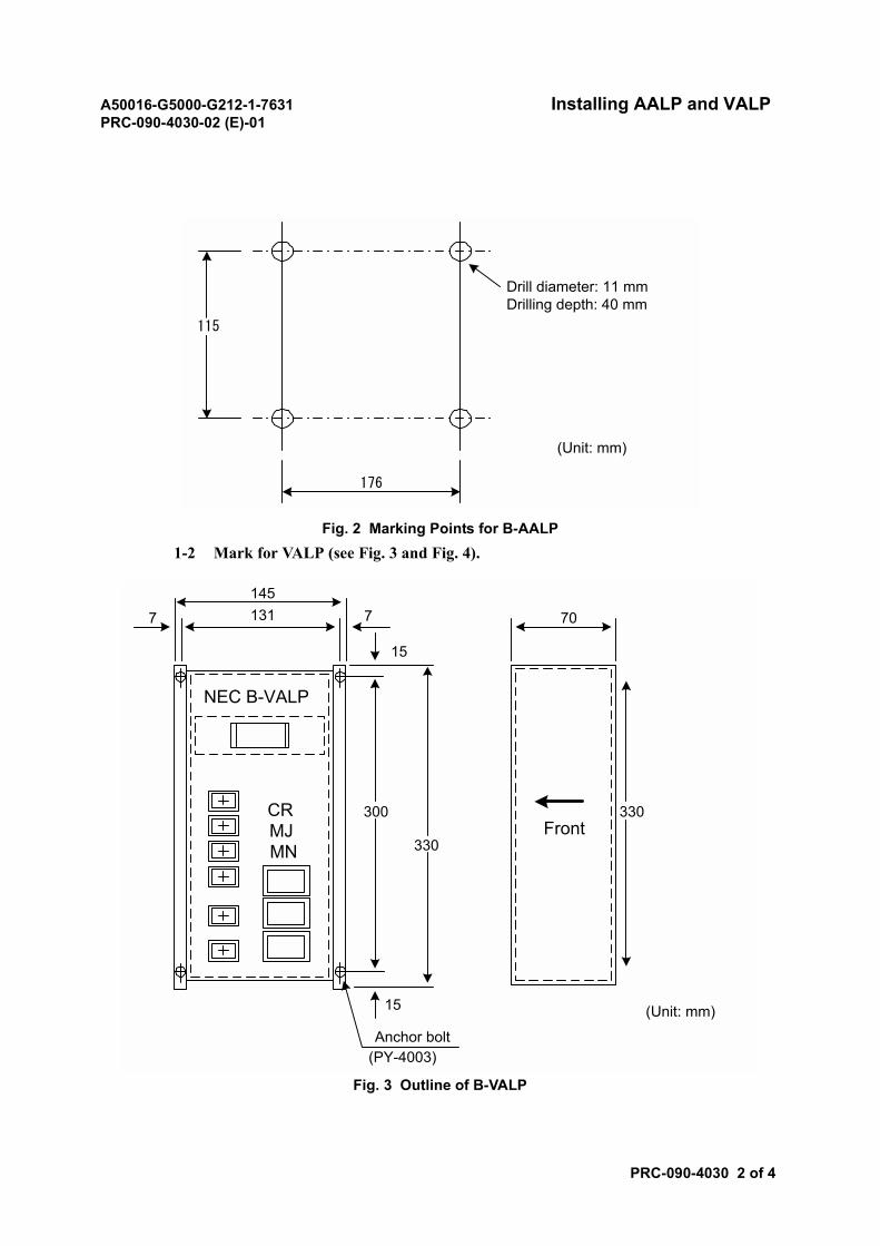
A50016-G5000-G212-1-7631 Installing AALP and VALPPRC-090-4030-02 (E)-01
PRC-090-4030 2 of 4
Fig. 2 Marking Points for B-AALP1-2 Mark for VALP (see Fig. 3 and Fig. 4).
Fig. 3 Outline of B-VALP
Drill diameter: 11 mmDrilling depth: 40 mm
176
(Unit: mm)
115
NEC B-VALP
1451317 7
15
70
300
330
15
330Front
Anchor bolt(PY-4003)
(Unit: mm)
CRMJMN
A50016-G5000-G212-1-7631 Installing AALP and VALPPRC-090-4030-02 (E)-01
PRC-090-4030 3 of 4
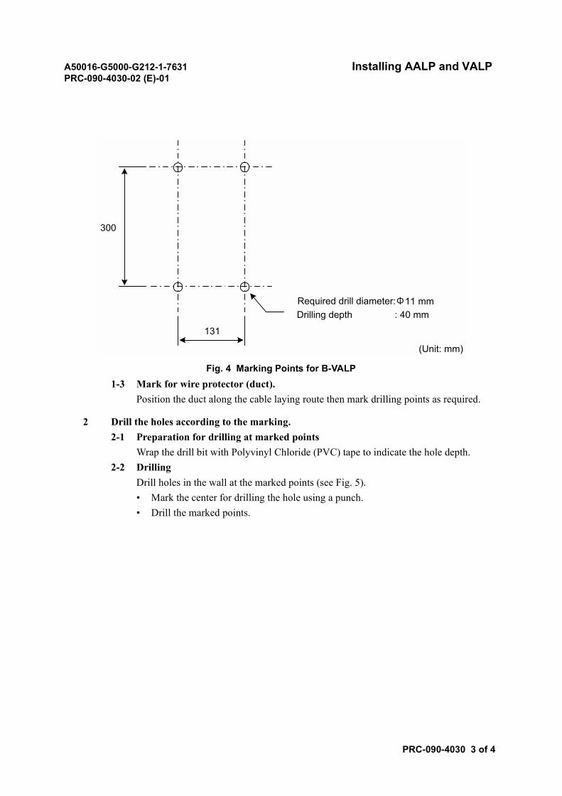
Fig. 4 Marking Points for B-VALP1-3 Mark for wire protector (duct).
Position the duct along the cable laying route then mark drilling points as required.
2 Drill the holes according to the marking.2-1 Preparation for drilling at marked points
Wrap the drill bit with Polyvinyl Chloride (PVC) tape to indicate the hole depth.2-2 Drilling
Drill holes in the wall at the marked points (see Fig. 5).• Mark the center for drilling the hole using a punch.• Drill the marked points.
300
131
Required drill diameter:Φ11 mmDrilling depth : 40 mm
(Unit: mm)
A50016-G5000-G212-1-7631 Installing AALP and VALPPRC-090-4030-02 (E)-01
PRC-090-4030 4 of 4
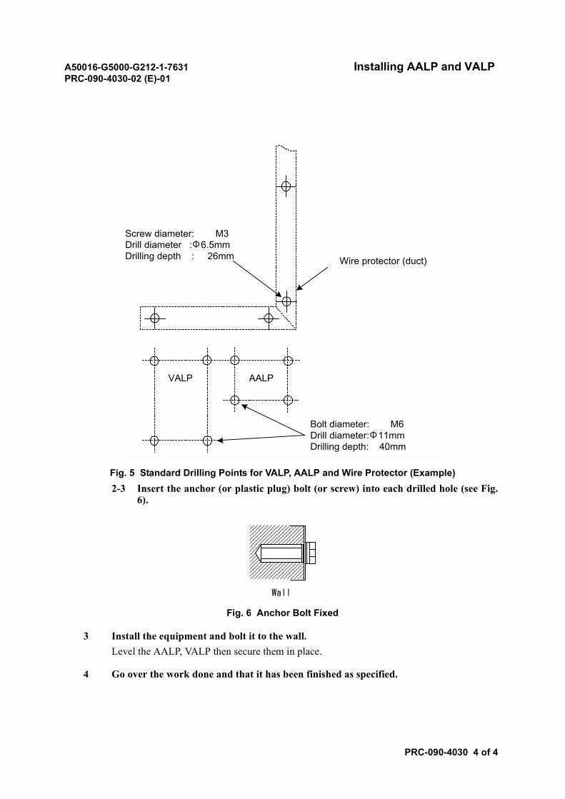
Fig. 5 Standard Drilling Points for VALP, AALP and Wire Protector (Example)2-3 Insert the anchor (or plastic plug) bolt (or screw) into each drilled hole (see Fig.
6).
Fig. 6 Anchor Bolt Fixed
3 Install the equipment and bolt it to the wall.Level the AALP, VALP then secure them in place.
4 Go over the work done and that it has been finished as specified.
Wire protector (duct)
VALP AALP
Screw diameter: M3Drill diameter :Φ6.5mmDrilling depth : 26mm
Bolt diameter: M6Drill diameter:Φ11mmDrilling depth: 40mm
Wall

A50016-G5000-G212-1-7631 Installing Maintenance EquipmentPRC-090-4040-02 (E)-01
PRC-090-4040 1 of 4
Installing Maintenance Equipment
1. REFERENCE INSTALLATION DRAWINGS
In this module, refer to the following installation drawing.
• Floor Layout
Note: Refer to the actual Physical Drawing.
A50016-G5000-G212-1-7631 Installing Maintenance EquipmentPRC-090-4040-02 (E)-01
PRC-090-4040 2 of 4
2. PROCEDURE
STEP ACTION/REMARKS
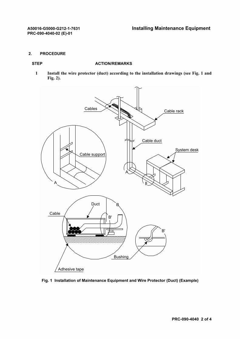
1 Install the wire protector (duct) according to the installation drawings (see Fig. 1 andFig. 2).
Fig. 1 Installation of Maintenance Equipment and Wire Protector (Duct) (Example)
System desk
Cable duct
Cable rackCables
Cable support
Cable
Duct
Adhesive tape
Bushing
A
BA
B'
B'
B
A50016-G5000-G212-1-7631 Installing Maintenance EquipmentPRC-090-4040-02 (E)-01
PRC-090-4040 3 of 4
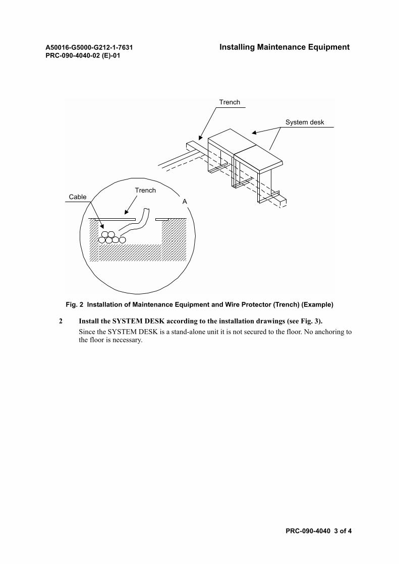
Fig. 2 Installation of Maintenance Equipment and Wire Protector (Trench) (Example)
2 Install the SYSTEM DESK according to the installation drawings (see Fig. 3).Since the SYSTEM DESK is a stand-alone unit it is not secured to the floor. No anchoring tothe floor is necessary.
Trench
TrenchCable
System desk
A
A50016-G5000-G212-1-7631 Installing Maintenance EquipmentPRC-090-4040-02 (E)-01
PRC-090-4040 4 of 4
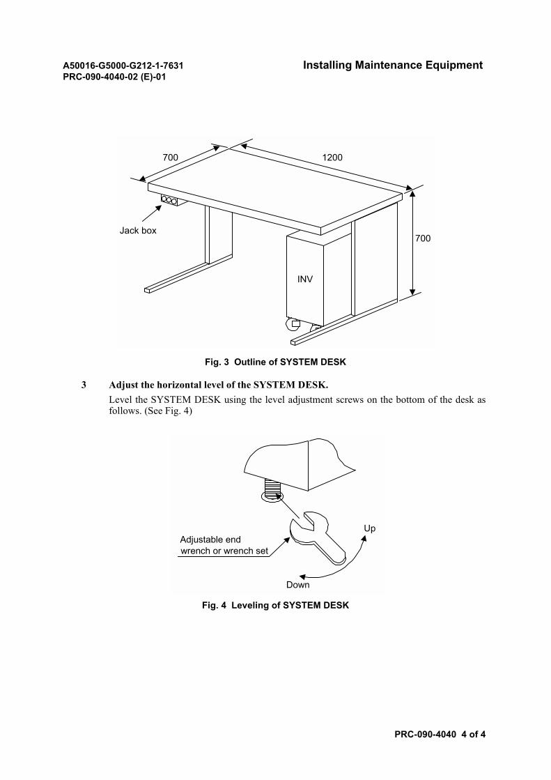
Fig. 3 Outline of SYSTEM DESK
3 Adjust the horizontal level of the SYSTEM DESK.Level the SYSTEM DESK using the level adjustment screws on the bottom of the desk asfollows. (See Fig. 4)
Fig. 4 Leveling of SYSTEM DESK
1200700
700
INV
Jack box
Up
Down
Adjustable endwrench or wrench set
A50016-G5000-G212-1-7631 Card InsertionPRC-090-4050-02 (E)-01
PRC-090-4050 1 of 2
Card Insertion
1. REFERENCE INSTALLATION DRAWINGS
In this module, refer to the following installation drawing.
• Face Layout
• Option Setting List
Note: Refer to the actual Physical Drawing or Option Setting List.
2. PROCEDURE
STEP ACTION/REMARKS
1 Determine the card positions using the installation drawings.Confirm the card positions according to the face layout in the installation drawings.Example: Card locations for P-8C4B<002>
2 Check the Option Setting List.Check if the option setting is necessary. If necessary, set referring to the Option Setting List.
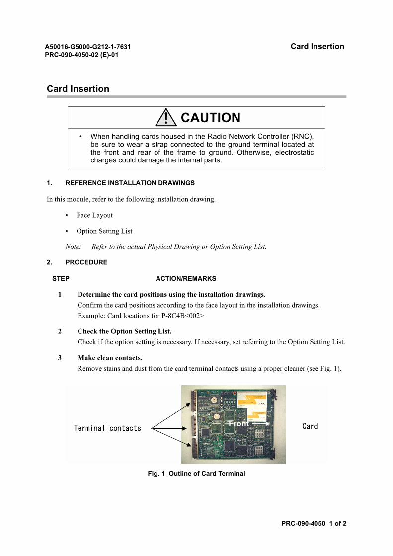
3 Make clean contacts.Remove stains and dust from the card terminal contacts using a proper cleaner (see Fig. 1).
Fig. 1 Outline of Card Terminal
CAUTION• When handling cards housed in the Radio Network Controller (RNC),
be sure to wear a strap connected to the ground terminal located atthe front and rear of the frame to ground. Otherwise, electrostaticcharges could damage the internal parts.
FrontTerminal contacts Card
A50016-G5000-G212-1-7631 Card InsertionPRC-090-4050-02 (E)-01
PRC-090-4050 2 of 2
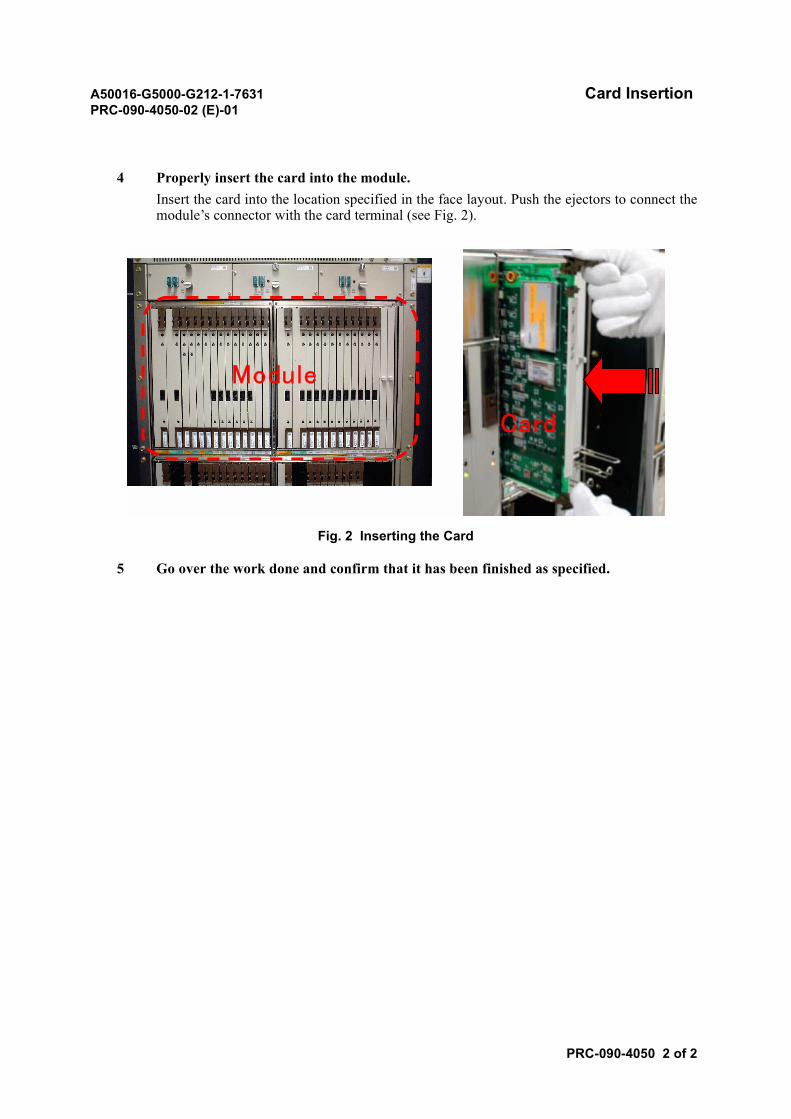
4 Properly insert the card into the module.Insert the card into the location specified in the face layout. Push the ejectors to connect themodule’s connector with the card terminal (see Fig. 2).
Fig. 2 Inserting the Card
5 Go over the work done and confirm that it has been finished as specified.
Module
Card
A50016-G5000-G212-1-7631 Module and Card Allocation CheckPRC-090-4060-02 (E)-01
PRC-090-4060 1 of 2
Module and Card Allocation Check
1. REFERENCE INSTALLATION DRAWINGS
In this module, refer to the following installation drawing.
• Face Layout
Note: Refer to the actual Physical Drawing.
2. PROCEDURE
STEP ACTION/REMARKS
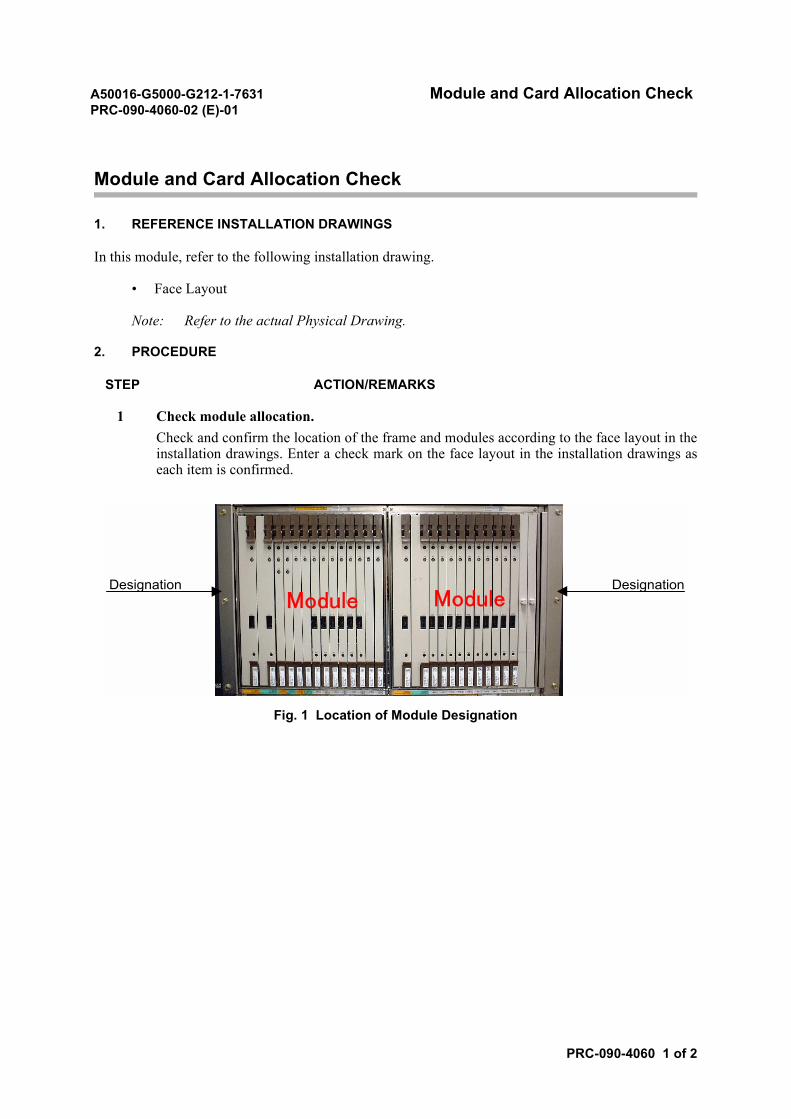
1 Check module allocation.Check and confirm the location of the frame and modules according to the face layout in theinstallation drawings. Enter a check mark on the face layout in the installation drawings aseach item is confirmed.
Fig. 1 Location of Module Designation
Designation DesignationModule Module
A50016-G5000-G212-1-7631 Module and Card Allocation CheckPRC-090-4060-02 (E)-01
PRC-090-4060 2 of 2
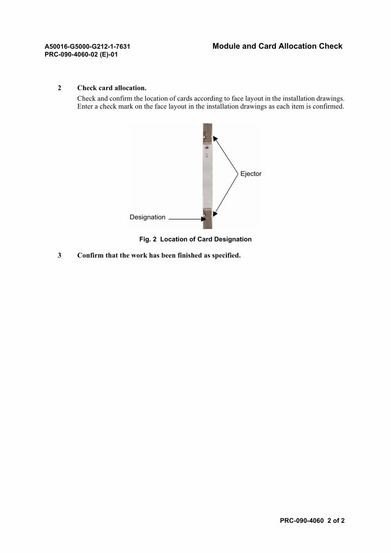
2 Check card allocation.Check and confirm the location of cards according to face layout in the installation drawings.Enter a check mark on the face layout in the installation drawings as each item is confirmed.
Fig. 2 Location of Card Designation
3 Confirm that the work has been finished as specified.
Ejector
Designation
A50016-G5000-G212-1-7631 DC-Power Cable LayingPRC-090-4070-02 (E)-02
PRC-090-4070 1 of 15
DC-Power Cable Laying
1. REFERENCE INSTALLATION DRAWINGS
In this module, refer to the following installation drawing.
• Power Distribution (DC)
Note: Refer to the actual Installation Drawing.
2. DC-POWER CABLE LAYING AND CONNECTION (BETWEEN RECTIFIER AND FRAMES)
2.1 Procedure
STEP ACTION/REMARKS
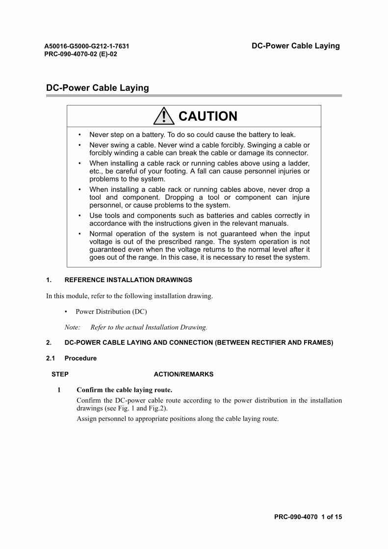
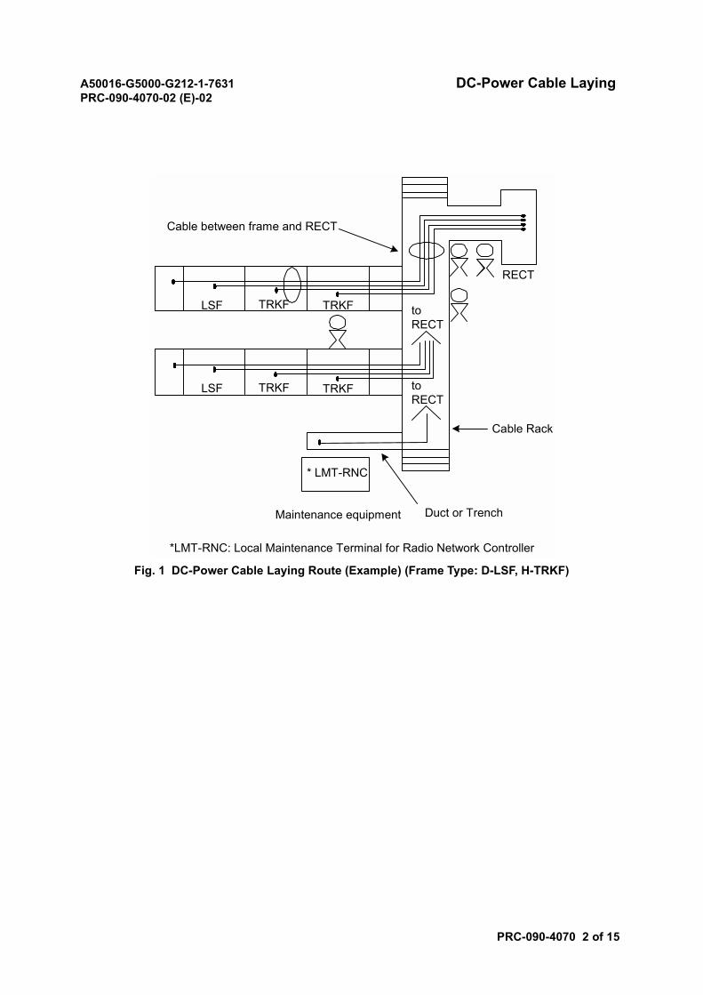
1 Confirm the cable laying route.Confirm the DC-power cable route according to the power distribution in the installationdrawings (see Fig. 1 and Fig.2).Assign personnel to appropriate positions along the cable laying route.
CAUTION• Never step on a battery. To do so could cause the battery to leak.• Never swing a cable. Never wind a cable forcibly. Swinging a cable or
forcibly winding a cable can break the cable or damage its connector.• When installing a cable rack or running cables above using a ladder,
etc., be careful of your footing. A fall can cause personnel injuries orproblems to the system.
• When installing a cable rack or running cables above, never drop atool and component. Dropping a tool or component can injurepersonnel, or cause problems to the system.
• Use tools and components such as batteries and cables correctly inaccordance with the instructions given in the relevant manuals.
• Normal operation of the system is not guaranteed when the inputvoltage is out of the prescribed range. The system operation is notguaranteed even when the voltage returns to the normal level after itgoes out of the range. In this case, it is necessary to reset the system.
A50016-G5000-G212-1-7631 DC-Power Cable LayingPRC-090-4070-02 (E)-02
PRC-090-4070 2 of 15
Fig. 1 DC-Power Cable Laying Route (Example) (Frame Type: D-LSF, H-TRKF)
RECT
toRECT
Cable between frame and RECT
toRECT
LSF
LSF
TRKF
TRKF
TRKF
TRKF
* LMT-RNC
Maintenance equipment Duct or Trench
Cable Rack
*LMT-RNC: Local Maintenance Terminal for Radio Network Controller
A50016-G5000-G212-1-7631 DC-Power Cable LayingPRC-090-4070-02 (E)-02
PRC-090-4070 3 of 15
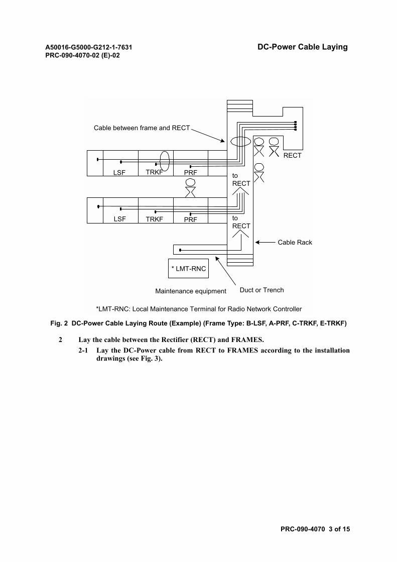
Fig. 2 DC-Power Cable Laying Route (Example) (Frame Type: B-LSF, A-PRF, C-TRKF, E-TRKF)
2 Lay the cable between the Rectifier (RECT) and FRAMES.2-1 Lay the DC-Power cable from RECT to FRAMES according to the installation
drawings (see Fig. 3).
RECT
toRECT
Cable between frame and RECT
toRECT
LSF
LSF
TRKF
TRKF
PRF
PRF
* LMT-RNC
Maintenance equipment Duct or Trench
Cable Rack
*LMT-RNC: Local Maintenance Terminal for Radio Network Controller
A50016-G5000-G212-1-7631 DC-Power Cable LayingPRC-090-4070-02 (E)-02
PRC-090-4070 4 of 15
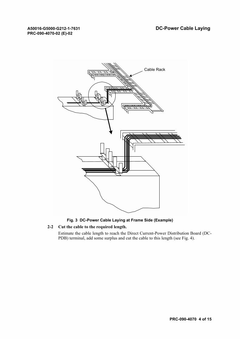
Fig. 3 DC-Power Cable Laying at Frame Side (Example)2-2 Cut the cable to the required length.
Estimate the cable length to reach the Direct Current-Power Distribution Board (DC-PDB) terminal, add some surplus and cut the cable to this length (see Fig. 4).
Cable Rack
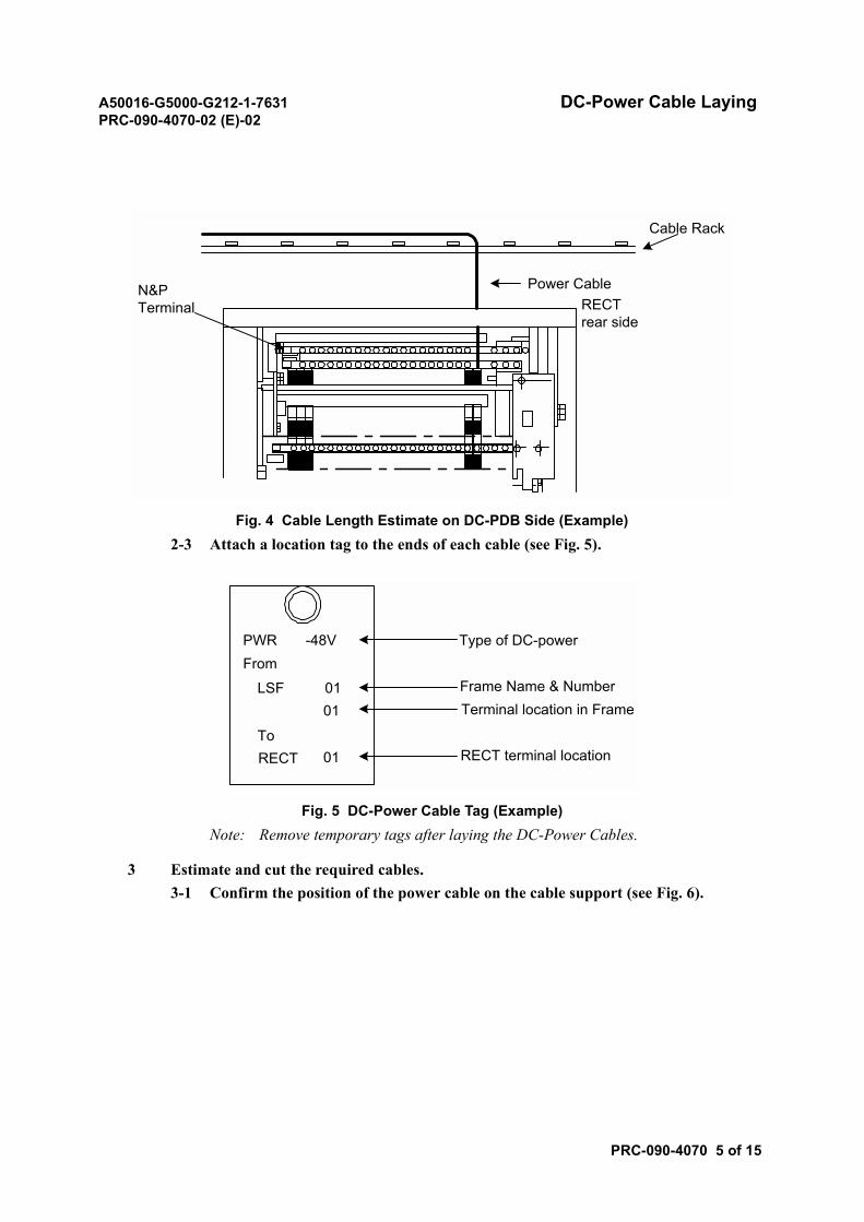
A50016-G5000-G212-1-7631 DC-Power Cable LayingPRC-090-4070-02 (E)-02
PRC-090-4070 5 of 15
Fig. 4 Cable Length Estimate on DC-PDB Side (Example)2-3 Attach a location tag to the ends of each cable (see Fig. 5).
Fig. 5 DC-Power Cable Tag (Example)Note: Remove temporary tags after laying the DC-Power Cables.
3 Estimate and cut the required cables.3-1 Confirm the position of the power cable on the cable support (see Fig. 6).
Cable Rack
Power CableRECTrear side
N&PTerminal
PWR -48VFrom
LSF 01 01
01ToRECT
Type of DC-power
Frame Name & NumberTerminal location in Frame
RECT terminal location
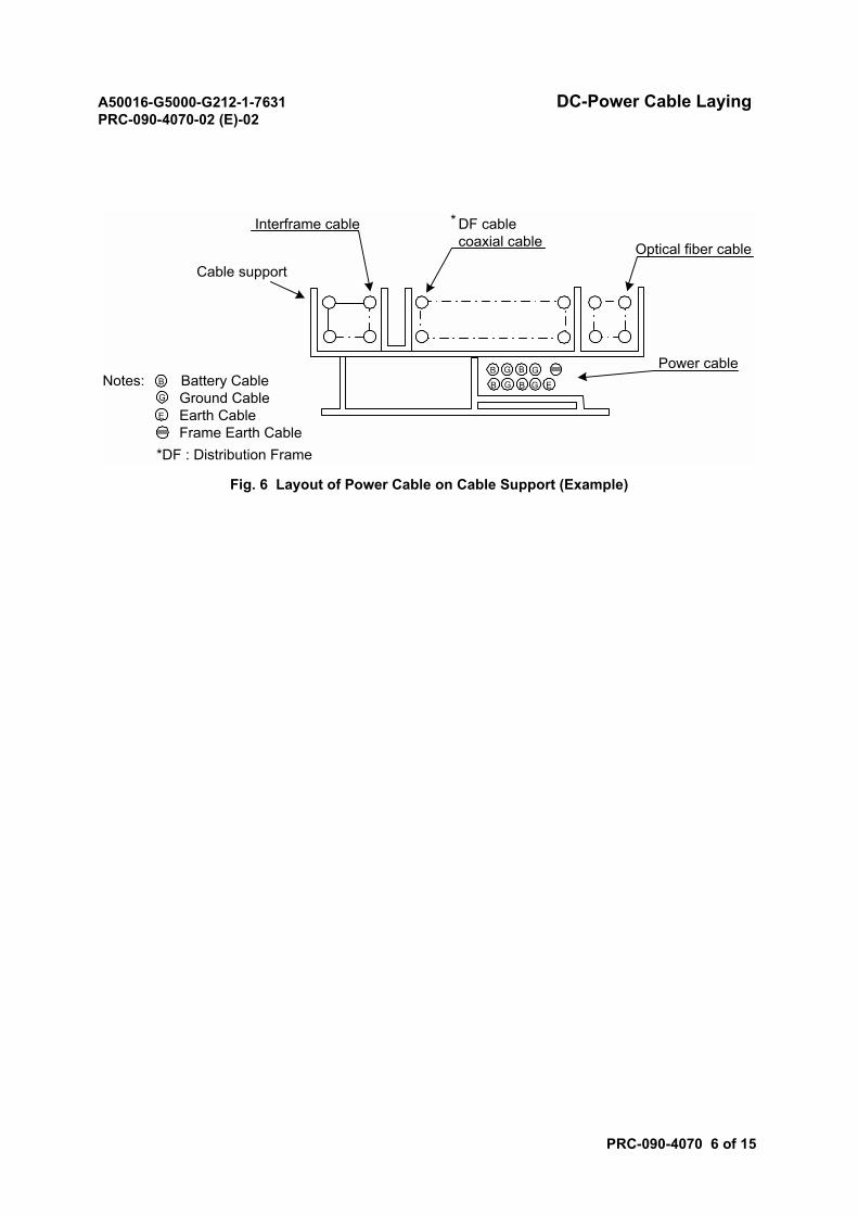
A50016-G5000-G212-1-7631 DC-Power Cable LayingPRC-090-4070-02 (E)-02
PRC-090-4070 6 of 15
Fig. 6 Layout of Power Cable on Cable Support (Example)
Optical fiber cable
Power cable
DF cablecoaxial cable
Interframe cable
Cable support
B
B B
B
G
G G
G ENotes: Battery Cable Ground Cable Earth Cable Frame Earth Cable
B
G
E
*
*DF : Distribution Frame
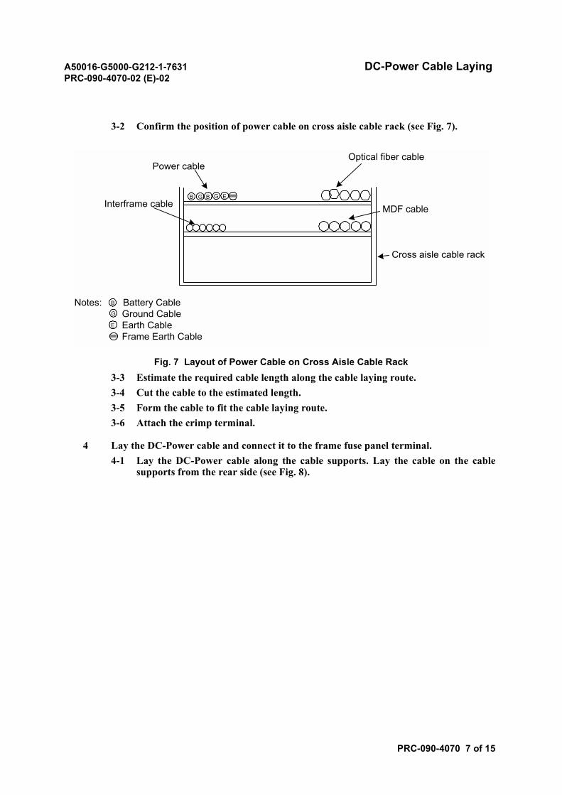
A50016-G5000-G212-1-7631 DC-Power Cable LayingPRC-090-4070-02 (E)-02
PRC-090-4070 7 of 15
3-2 Confirm the position of power cable on cross aisle cable rack (see Fig. 7).
Fig. 7 Layout of Power Cable on Cross Aisle Cable Rack3-3 Estimate the required cable length along the cable laying route.3-4 Cut the cable to the estimated length.3-5 Form the cable to fit the cable laying route.3-6 Attach the crimp terminal.
4 Lay the DC-Power cable and connect it to the frame fuse panel terminal.4-1 Lay the DC-Power cable along the cable supports. Lay the cable on the cable
supports from the rear side (see Fig. 8).
Optical fiber cablePower cable
Interframe cable
Notes: Battery Cable Ground Cable Earth Cable Frame Earth Cable
B
G
E
MDF cable
Cross aisle cable rack
B BG G E
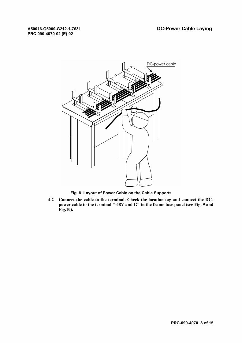
A50016-G5000-G212-1-7631 DC-Power Cable LayingPRC-090-4070-02 (E)-02
PRC-090-4070 8 of 15
Fig. 8 Layout of Power Cable on the Cable Supports4-2 Connect the cable to the terminal. Check the location tag and connect the DC-
power cable to the terminal "-48V and G" in the frame fuse panel (see Fig. 9 andFig.10).
DC-power cable
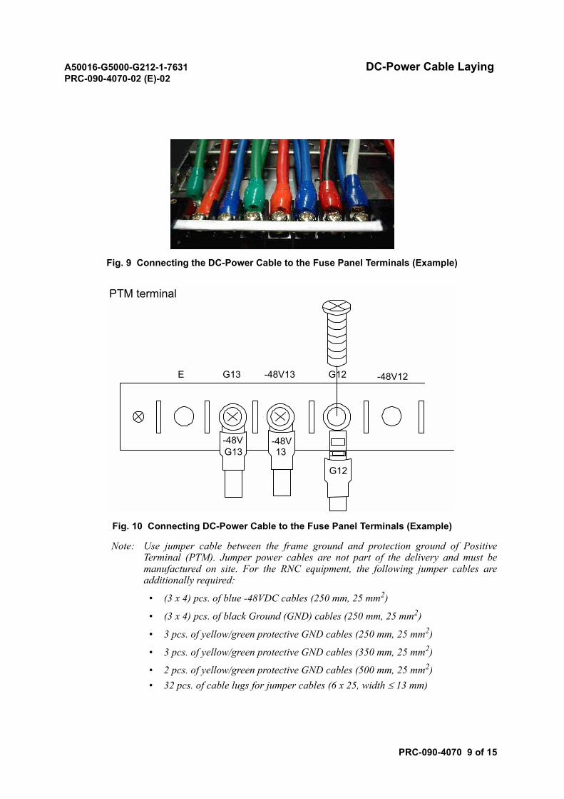
A50016-G5000-G212-1-7631 DC-Power Cable LayingPRC-090-4070-02 (E)-02
PRC-090-4070 9 of 15
Fig. 9 Connecting the DC-Power Cable to the Fuse Panel Terminals (Example)
Fig. 10 Connecting DC-Power Cable to the Fuse Panel Terminals (Example)
Note: Use jumper cable between the frame ground and protection ground of PositiveTerminal (PTM). Jumper power cables are not part of the delivery and must bemanufactured on site. For the RNC equipment, the following jumper cables areadditionally required:
• (3 x 4) pcs. of blue -48VDC cables (250 mm, 25 mm2)
• (3 x 4) pcs. of black Ground (GND) cables (250 mm, 25 mm2)
• 3 pcs. of yellow/green protective GND cables (250 mm, 25 mm2)
• 3 pcs. of yellow/green protective GND cables (350 mm, 25 mm2)
• 2 pcs. of yellow/green protective GND cables (500 mm, 25 mm2)• 32 pcs. of cable lugs for jumper cables (6 x 25, width ≤ 13 mm)
PTM terminal
G13
-48V -48V
E -48V13 G12 -48V12
G12
13G13
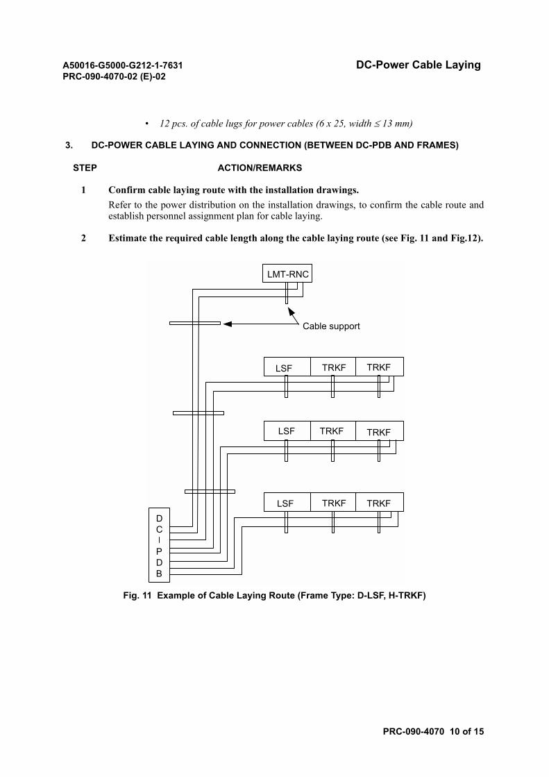
A50016-G5000-G212-1-7631 DC-Power Cable LayingPRC-090-4070-02 (E)-02
PRC-090-4070 10 of 15
• 12 pcs. of cable lugs for power cables (6 x 25, width ≤ 13 mm)
3. DC-POWER CABLE LAYING AND CONNECTION (BETWEEN DC-PDB AND FRAMES)
STEP ACTION/REMARKS
1 Confirm cable laying route with the installation drawings.Refer to the power distribution on the installation drawings, to confirm the cable route andestablish personnel assignment plan for cable laying.
2 Estimate the required cable length along the cable laying route (see Fig. 11 and Fig.12).
Fig. 11 Example of Cable Laying Route (Frame Type: D-LSF, H-TRKF)
Cable support
LMT-RNC
LSF TRKF TRKF
LSF TRKF
LSF TRKFDC
PDB
TRKF
TRKF
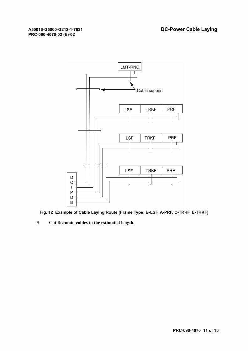
A50016-G5000-G212-1-7631 DC-Power Cable LayingPRC-090-4070-02 (E)-02
PRC-090-4070 11 of 15
Fig. 12 Example of Cable Laying Route (Frame Type: B-LSF, A-PRF, C-TRKF, E-TRKF)
3 Cut the main cables to the estimated length.
Cable support
LMT-RNC
LSF TRKF PRF
LSF TRKF PRF
LSF TRKF PRFDC
PDB
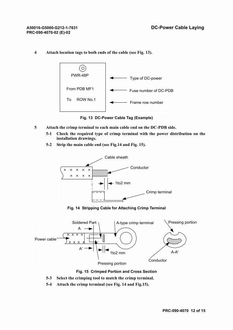
A50016-G5000-G212-1-7631 DC-Power Cable LayingPRC-090-4070-02 (E)-02
PRC-090-4070 12 of 15
4 Attach location tags to both ends of the cable (see Fig. 13).
Fig. 13 DC-Power Cable Tag (Example)
5 Attach the crimp terminal to each main cable end on the DC-PDB side.5-1 Check the required type of crimp terminal with the power distribution on the
installation drawings.5-2 Strip the main cable end (see Fig.14 and Fig. 15).
Fig. 14 Stripping Cable for Attaching Crimp Terminal
Fig. 15 Crimped Portion and Cross Section5-3 Select the crimping tool to match the crimp terminal.5-4 Attach the crimp terminal (see Fig. 14 and Fig.15).
Type of DC-power
Fuse number of DC-PDB
Frame row number
PWR-48P
From PDB MF1
To ROW No.1
Cable sheath
Conductor
1to2 mm
Crimp terminal
Conductor
1to2 mm
A-type crimp terminal
Power cable
Soldered PartA
A'
Pressing portion
Pressing portion
A-A'
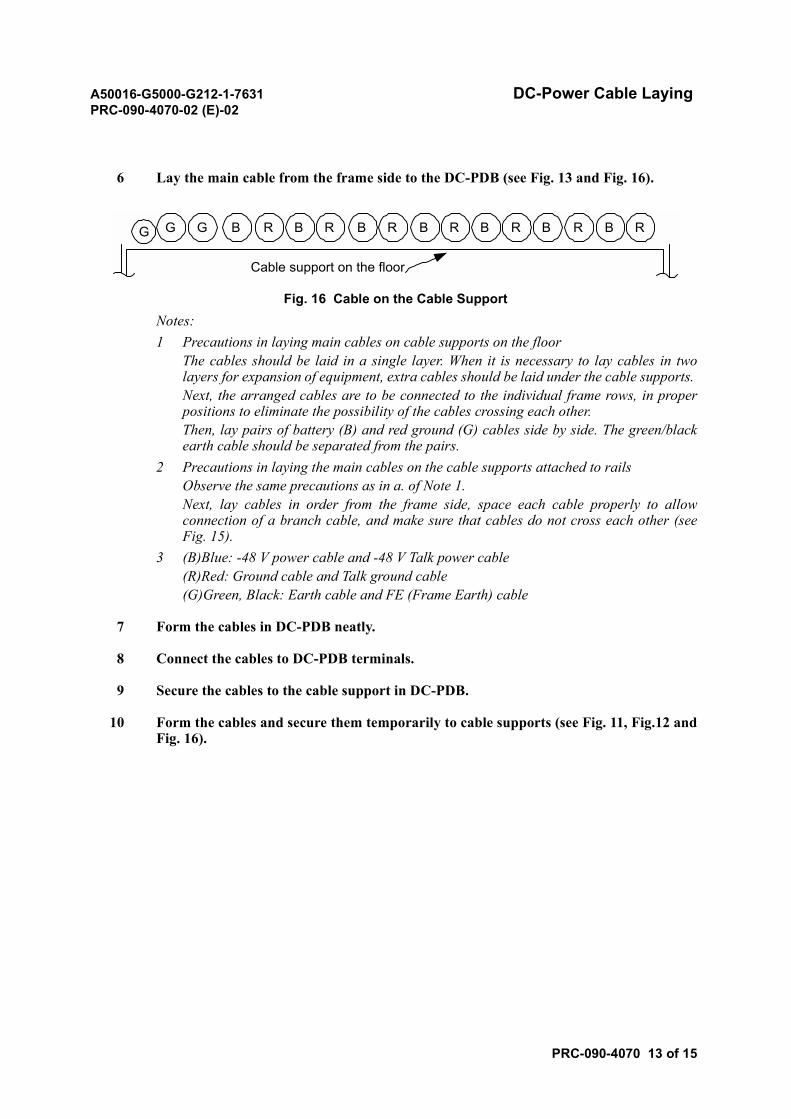
A50016-G5000-G212-1-7631 DC-Power Cable LayingPRC-090-4070-02 (E)-02
PRC-090-4070 13 of 15
6 Lay the main cable from the frame side to the DC-PDB (see Fig. 13 and Fig. 16).
Fig. 16 Cable on the Cable SupportNotes:1 Precautions in laying main cables on cable supports on the floor
The cables should be laid in a single layer. When it is necessary to lay cables in twolayers for expansion of equipment, extra cables should be laid under the cable supports. Next, the arranged cables are to be connected to the individual frame rows, in properpositions to eliminate the possibility of the cables crossing each other.Then, lay pairs of battery (B) and red ground (G) cables side by side. The green/blackearth cable should be separated from the pairs.
2 Precautions in laying the main cables on the cable supports attached to railsObserve the same precautions as in a. of Note 1. Next, lay cables in order from the frame side, space each cable properly to allowconnection of a branch cable, and make sure that cables do not cross each other (seeFig. 15).
3 (B)Blue: -48 V power cable and -48 V Talk power cable(R)Red: Ground cable and Talk ground cable(G)Green, Black: Earth cable and FE (Frame Earth) cable
7 Form the cables in DC-PDB neatly.
8 Connect the cables to DC-PDB terminals.
9 Secure the cables to the cable support in DC-PDB.
10 Form the cables and secure them temporarily to cable supports (see Fig. 11, Fig.12 andFig. 16).
Cable support on the floor
G G B B B B B B BR R R R R R RG
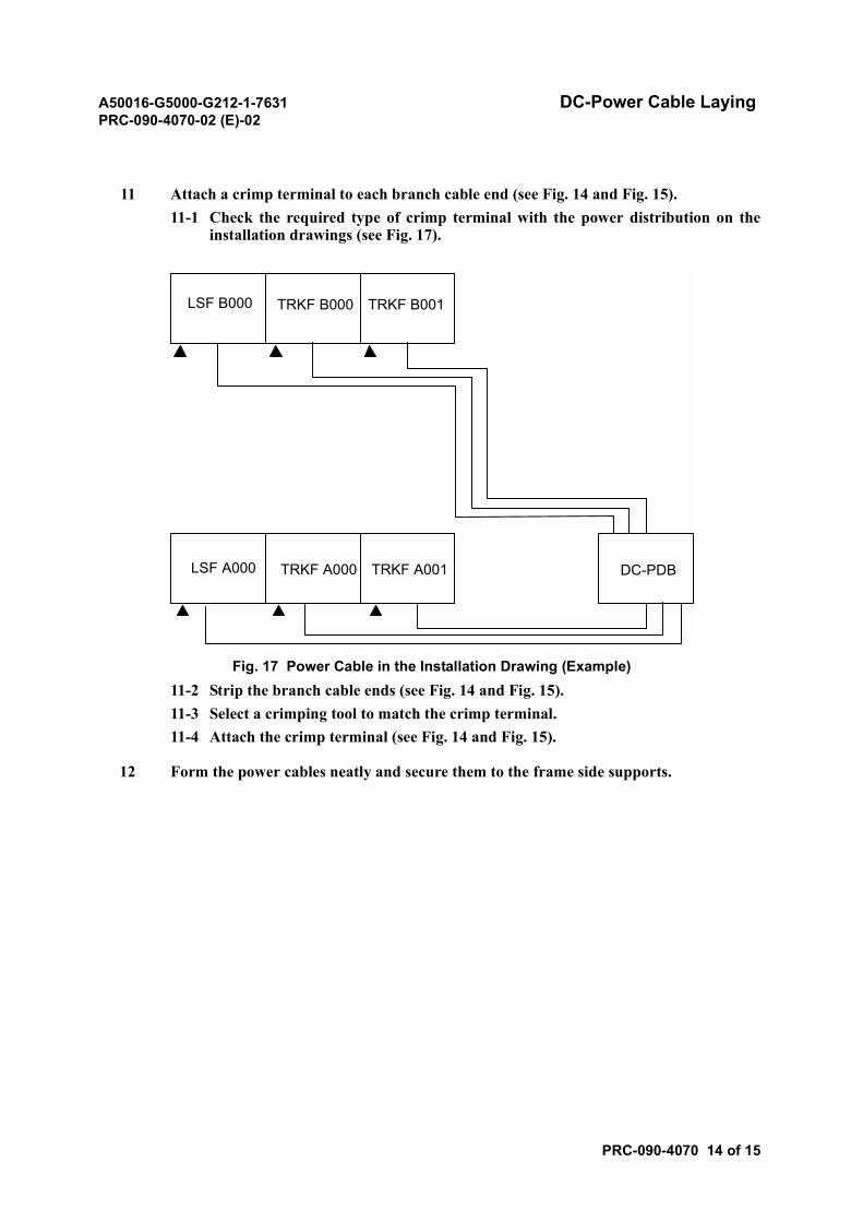
A50016-G5000-G212-1-7631 DC-Power Cable LayingPRC-090-4070-02 (E)-02
PRC-090-4070 14 of 15
11 Attach a crimp terminal to each branch cable end (see Fig. 14 and Fig. 15).11-1 Check the required type of crimp terminal with the power distribution on the
installation drawings (see Fig. 17).
Fig. 17 Power Cable in the Installation Drawing (Example)11-2 Strip the branch cable ends (see Fig. 14 and Fig. 15).11-3 Select a crimping tool to match the crimp terminal. 11-4 Attach the crimp terminal (see Fig. 14 and Fig. 15).
12 Form the power cables neatly and secure them to the frame side supports.
LSF B000 TRKF B000 TRKF B001
DC-PDBLSF A000 TRKF A000 TRKF A001

A50016-G5000-G212-1-7631 DC-Power Cable LayingPRC-090-4070-02 (E)-02
PRC-090-4070 15 of 15
4. ADDITIONAL INFORMATION
4.1 Dimensioning of Breakers within Power Supply Unit for RNC (Frame Type: D-LSF, H-TRKF)
Each -48V power supply cable shall be secured with one 80A breaker, assuming that two (2) -48V/0Vpairs are connected to each frame (Positive Terminal (PTM) 0 and PTM 1).
If the two (2) -48V terminals are short-circuited on the power unit side (coming from one source, buttwo (2) terminals), then 63A breakers are sufficient for each -48V cable (see Fig. 18 and Fig. 19).
Fig. 18 Independent Sources for Different -48V Terminals
Fig. 19 One Source for Different -48V Terminals
PTM 0
PTM 1
RNC Frame-48V
-48V
80A Breaker
80A Breaker
Power Supply Unit
AC/DCrectifier
AC/DCrectifier
Ground (0V) cablesnot shown
PTM 0
PTM 1
RNC Frame-48V
-48V
63A Breaker
63A Breaker
Power Supply Unit
AC/DCrectifier
Ground (0V) cablesnot shown

A50016-G5000-G212-1-7631 Earth and Frame Earth Cable LayingPRC-090-4080-02 (E)-02
PRC-090-4080 1 of 7
Earth and Frame Earth Cable Laying
1. REFERENCE INSTALLATION DRAWINGS
In this module, refer to the following installation drawing.
• Earth Cable Diagram
Note: Refer to the actual Installation Drawing.
2. PROCEDURE
STEP ACTION/REMARKS
1 Confirm the cable laying route.Confirm the cable route with the installation drawings. Assign personnel to appropriatepositions along the cable laying route.
2 Lay the E cable.2-1 Lay the E Cable from the MGB according to the installation drawings.2-2 Cut the cable to the required length.
Estimate the cable length to reach the MGB terminal add some surplus and cut thecable to this length.
2-3 Attach a location tag to each cable end.Note: Remove the temporary tags after laying the E and FE Cables.
CAUTION• Never step on a battery. To do so could cause the battery to leak.• Never swing a cable. Never wind a cable forcibly. Swinging a cable or
forcibly winding a cable can break the cable or damage its connector.• When installing a cable rack or running cables above using a ladder,
etc., watch your footing. A fall could result in personnel injuries orcause problems to the system.
• When installing a cable rack or running cables above, be careful notto drop any tool or component. Dropping a tool or a component caninjure other persons, or can cause problems to the system.
• Use tools and components such as batteries and cables correctly inaccordance with the instructions given in the relevant manuals.
• Normal operation of the system is not guaranteed when the inputvoltage is out of the prescribed range. The system operation is notguaranteed even when the voltage returns to the normal level after itbecomes out of the range. In this case, it is necessary to reset thesystem.
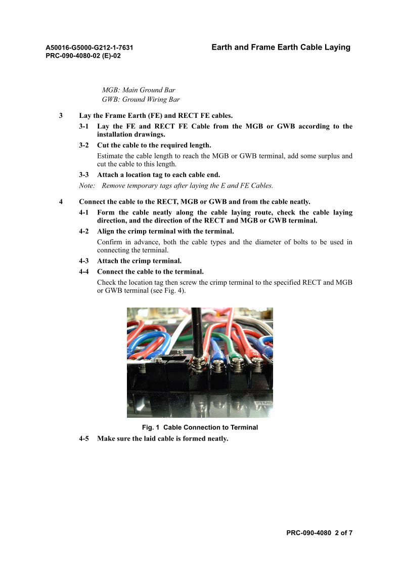
A50016-G5000-G212-1-7631 Earth and Frame Earth Cable LayingPRC-090-4080-02 (E)-02
PRC-090-4080 2 of 7
MGB: Main Ground BarGWB: Ground Wiring Bar
3 Lay the Frame Earth (FE) and RECT FE cables.3-1 Lay the FE and RECT FE Cable from the MGB or GWB according to the
installation drawings.3-2 Cut the cable to the required length.
Estimate the cable length to reach the MGB or GWB terminal, add some surplus andcut the cable to this length.
3-3 Attach a location tag to each cable end.Note: Remove temporary tags after laying the E and FE Cables.
4 Connect the cable to the RECT, MGB or GWB and from the cable neatly.4-1 Form the cable neatly along the cable laying route, check the cable laying
direction, and the direction of the RECT and MGB or GWB terminal.4-2 Align the crimp terminal with the terminal.
Confirm in advance, both the cable types and the diameter of bolts to be used inconnecting the terminal.
4-3 Attach the crimp terminal.4-4 Connect the cable to the terminal.
Check the location tag then screw the crimp terminal to the specified RECT and MGBor GWB terminal (see Fig. 4).
Fig. 1 Cable Connection to Terminal4-5 Make sure the laid cable is formed neatly.
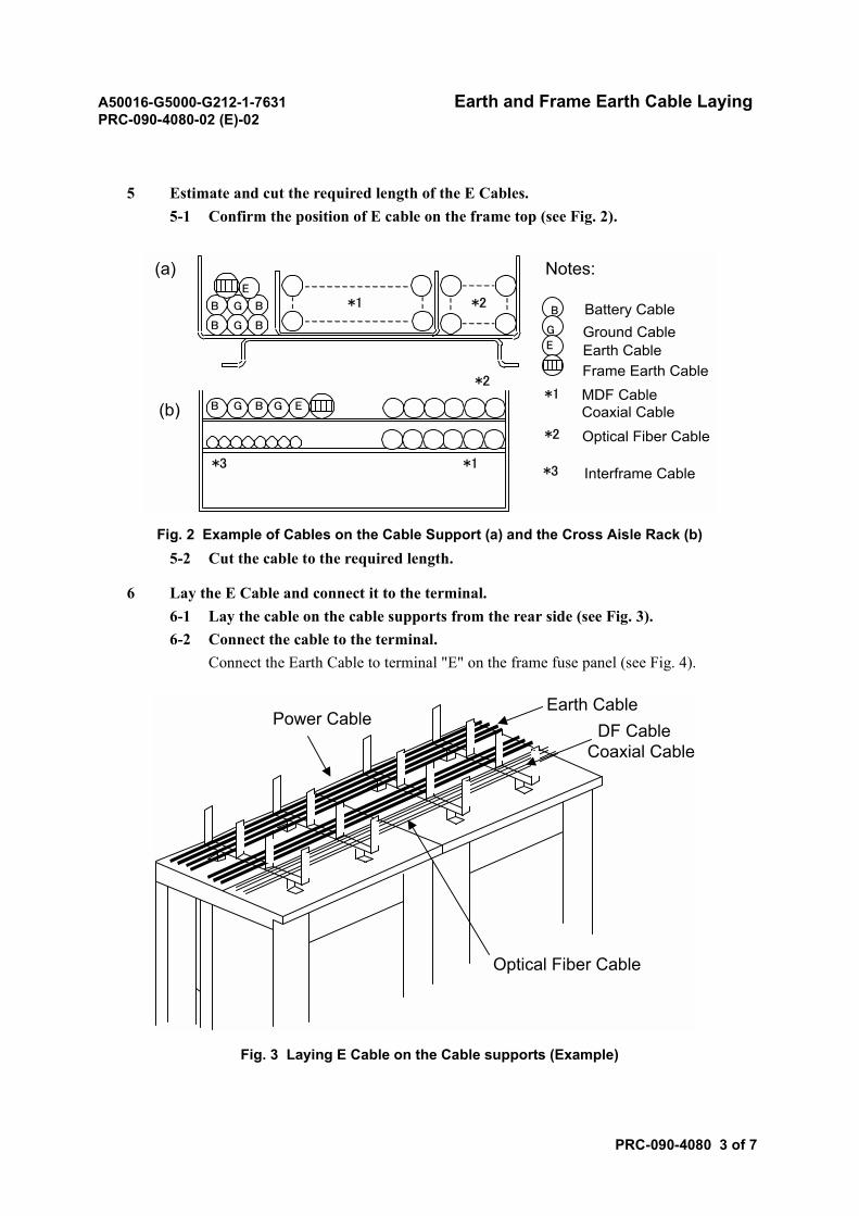
A50016-G5000-G212-1-7631 Earth and Frame Earth Cable LayingPRC-090-4080-02 (E)-02
PRC-090-4080 3 of 7
5 Estimate and cut the required length of the E Cables.5-1 Confirm the position of E cable on the frame top (see Fig. 2).
Fig. 2 Example of Cables on the Cable Support (a) and the Cross Aisle Rack (b)5-2 Cut the cable to the required length.
6 Lay the E Cable and connect it to the terminal.6-1 Lay the cable on the cable supports from the rear side (see Fig. 3).6-2 Connect the cable to the terminal.
Connect the Earth Cable to terminal "E" on the frame fuse panel (see Fig. 4).
Fig. 3 Laying E Cable on the Cable supports (Example)
GB GB E
GB B
GB B
*1 *2
*1
*2
*3
E
B
G
E
(a)
(b)*1
Notes:
Battery CableGround CableEarth CableFrame Earth CableMDF CableCoaxial Cable
*2 Optical Fiber Cable
*3 Interframe Cable
Optical Fiber Cable
Earth CableDF Cable
Coaxial Cable
Power Cable

A50016-G5000-G212-1-7631 Earth and Frame Earth Cable LayingPRC-090-4080-02 (E)-02
PRC-090-4080 4 of 7
Fig. 4 Connecting Cables to the Frame Terminal
7 Estimate and cut the required length of the Frame Earth (FE) cables.7-1 Estimate the required cable length along the cable laying route.7-2 Cut the cable to the estimated length.
8 Lay the FE Cable and connect it to the terminal.8-1 Lay the Earth Cable on the cable supports from the rear side (see Fig. 3).8-2 Connect the cable to the terminal.
Connect the Frame Earth Cable to terminal "FE" on the Frame Terminal (see Fig. 4).
9 Secure the cable to the cable supports and cable rack, and terminate the cable ends.Form the cable neatly and secure it to the cable support and cable rack with tie wraps.9-1 Secure the cable to the cable supports.9-2 Secure the cable to the cable rack.
For a horizontal cable rack, secure each cable to the cable supports with tie wraps (seeFig. 5).
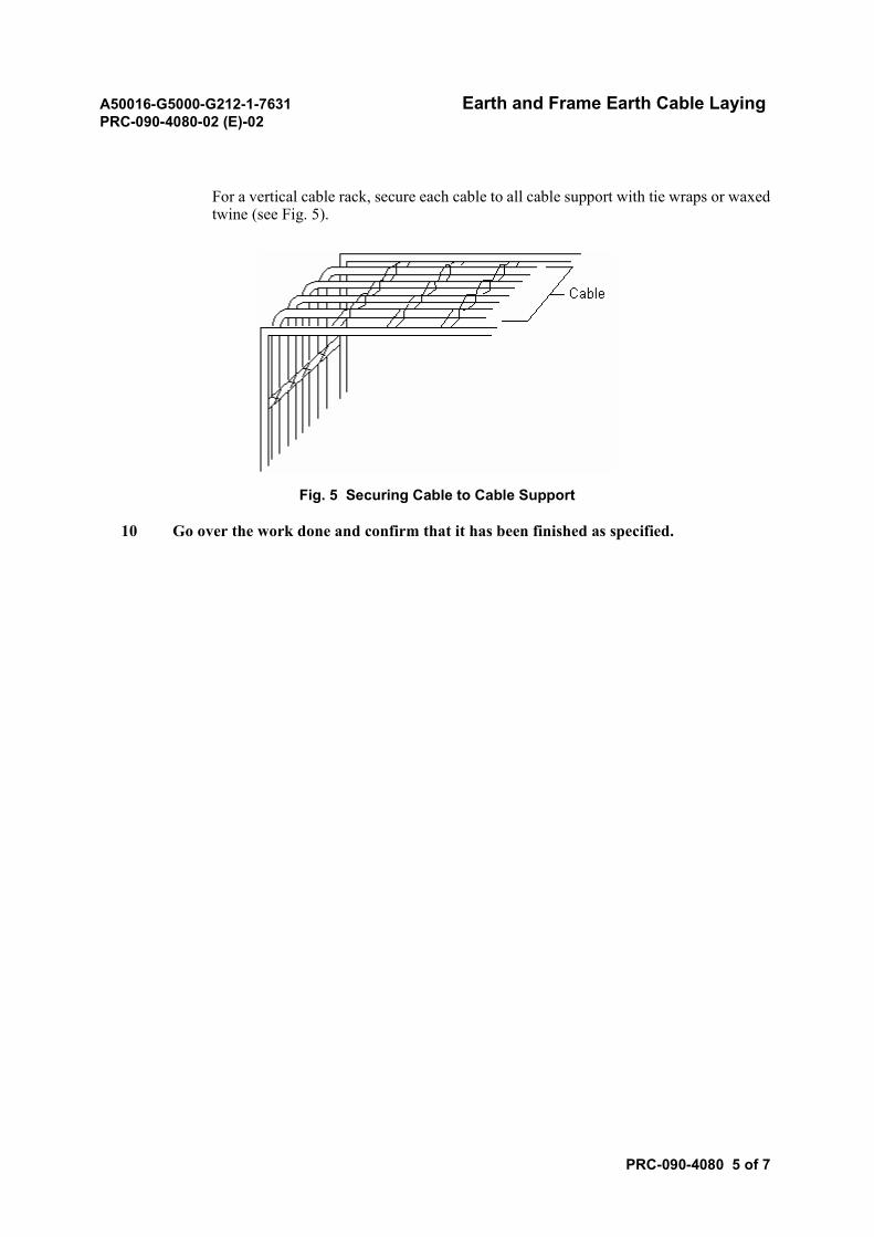
A50016-G5000-G212-1-7631 Earth and Frame Earth Cable LayingPRC-090-4080-02 (E)-02
PRC-090-4080 5 of 7
For a vertical cable rack, secure each cable to all cable support with tie wraps or waxedtwine (see Fig. 5).
Fig. 5 Securing Cable to Cable Support
10 Go over the work done and confirm that it has been finished as specified.
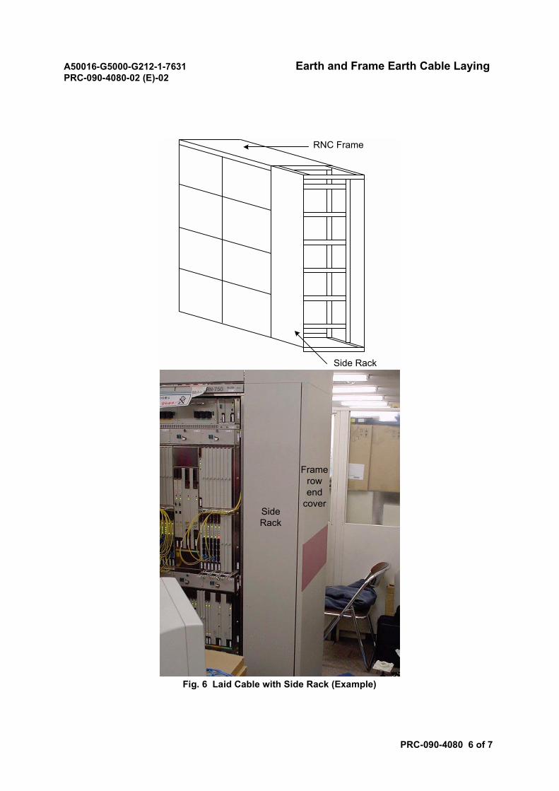
A50016-G5000-G212-1-7631 Earth and Frame Earth Cable LayingPRC-090-4080-02 (E)-02
PRC-090-4080 6 of 7
Fig. 6 Laid Cable with Side Rack (Example)
Framerowend
coverSideRack
Side Rack
RNC Frame
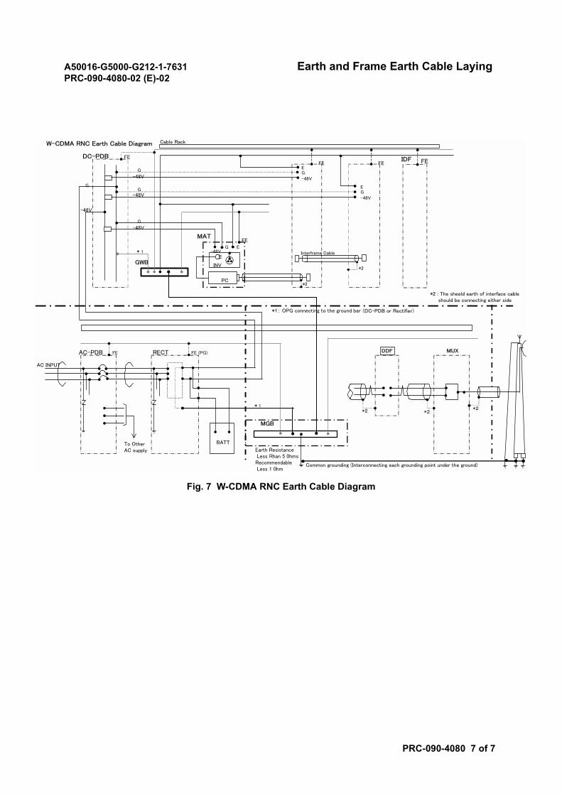
A50016-G5000-G212-1-7631 Earth and Frame Earth Cable LayingPRC-090-4080-02 (E)-02
PRC-090-4080 7 of 7
Fig. 7 W-CDMA RNC Earth Cable Diagram
W-CDMA RNC Earth Cable Diagram
FEDC-PDB
INV
PC
MAT
-48VG E
Interframe Cable
*2
*2
FE
FEFE
EG-48V
EG-48V
FE
AC-PDB FE RECT FE (PG)
AC INPUT
To OtherAC supply
-48V
G
G
-48V
G-48V
G
-48V
BATT
Common grounding (Interconnecting each grounding point under the ground)
Earth Resistance Less Rhan 5 0hmsRecommendable Less 1 0hm
*1: OPG connecting to the ground bar (DC-PDB or Rectifier)
Cable Rack
MGB
GWB
MUXDDF
● ●
*2 : The sheeld earth of interface cable should be connecting either side
IDF
*1
*2*2
*2*1
A50016-G5000-G212-1-7631 Laying Power Cable for Maintenance EquipmentPRC-090-4090-02 (E)-01
PRC-090-4090 1 of 4
Laying Power Cable for Maintenance Equipment
1. REFERENCE INSTALLATION DRAWINGS
In this module, refer to the following installation drawing.
• Power Distribution (DC)
Note: Refer to the actual Installation Drawing.
2. DC-POWER CABLE LAYING
2.1 Procedure
STEP ACTION/REMARKS
1 Estimate and cut required length of DC-Power cables.1-1 Estimate the required cable length along the cable laying route (see Fig. 1).
CAUTION• Never step on a battery. To do so could cause the battery to leak.• Never swing a cable. Never wind a cable forcibly. Swinging a cable or
forcibly winding a cable can break the cable or damage its connector.• When installing a cable rack or running cables above using a ladder,
etc., watch your footing. A fall could result in personnel injuries orcause problems to the system.
• When installing a cable rack or running cables above, be careful notto drop any tool or component. Dropping a tool or a component caninjure other persons, or can cause problems to the system.
• Use tools and components such as batteries and cables correctly inaccordance with the instructions given in the relevant manuals.
• Normal operation of the system is not guaranteed when the inputvoltage is out of the prescribed range. The system operation is notguaranteed even when the voltage returns to the normal level after itbecomes out of the range. In this case, it is necessary to reset thesystem.
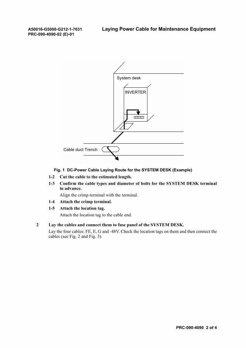
A50016-G5000-G212-1-7631 Laying Power Cable for Maintenance EquipmentPRC-090-4090-02 (E)-01
PRC-090-4090 2 of 4
Fig. 1 DC-Power Cable Laying Route for the SYSTEM DESK (Example)1-2 Cut the cable to the estimated length.1-3 Confirm the cable types and diameter of bolts for the SYSTEM DESK terminal
in advance.Align the crimp terminal with the terminal.
1-4 Attach the crimp terminal.1-5 Attach the location tag.
Attach the location tag to the cable end.
2 Lay the cables and connect them to fuse panel of the SYSTEM DESK.Lay the four cables: FE, E, G and -48V. Check the location tags on them and then connect thecables (see Fig. 2 and Fig. 3).
System desk
Cable duct Trench
INVERTER
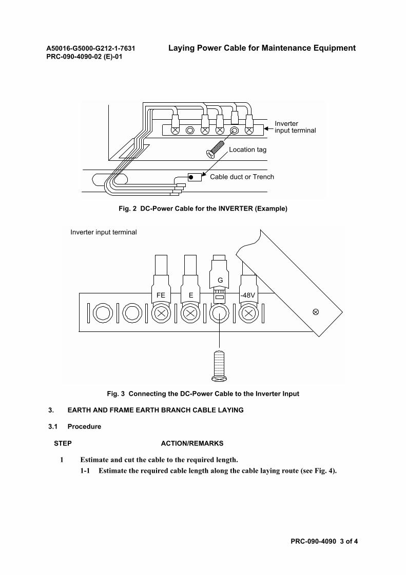
A50016-G5000-G212-1-7631 Laying Power Cable for Maintenance EquipmentPRC-090-4090-02 (E)-01
PRC-090-4090 3 of 4
Fig. 2 DC-Power Cable for the INVERTER (Example)
Fig. 3 Connecting the DC-Power Cable to the Inverter Input
3. EARTH AND FRAME EARTH BRANCH CABLE LAYING
3.1 Procedure
STEP ACTION/REMARKS
1 Estimate and cut the cable to the required length.1-1 Estimate the required cable length along the cable laying route (see Fig. 4).
Inverterinput terminal
Location tag
Cable duct or Trench
FE E
G
-48V
Inverter input terminal
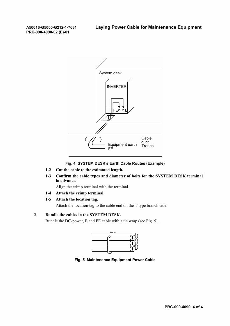
A50016-G5000-G212-1-7631 Laying Power Cable for Maintenance EquipmentPRC-090-4090-02 (E)-01
PRC-090-4090 4 of 4
Fig. 4 SYSTEM DESK’s Earth Cable Routes (Example)1-2 Cut the cable to the estimated length.1-3 Confirm the cable types and diameter of bolts for the SYSTEM DESK terminal
in advance.Align the crimp terminal with the terminal.
1-4 Attach the crimp terminal.1-5 Attach the location tag.
Attach the location tag to the cable end on the T-type branch side.
2 Bundle the cables in the SYSTEM DESK.Bundle the DC-power, E and FE cable with a tie wrap (see Fig. 5).
Fig. 5 Maintenance Equipment Power Cable
System desk
INVERTER
CableductTrench
EFE
FEEquipment earth
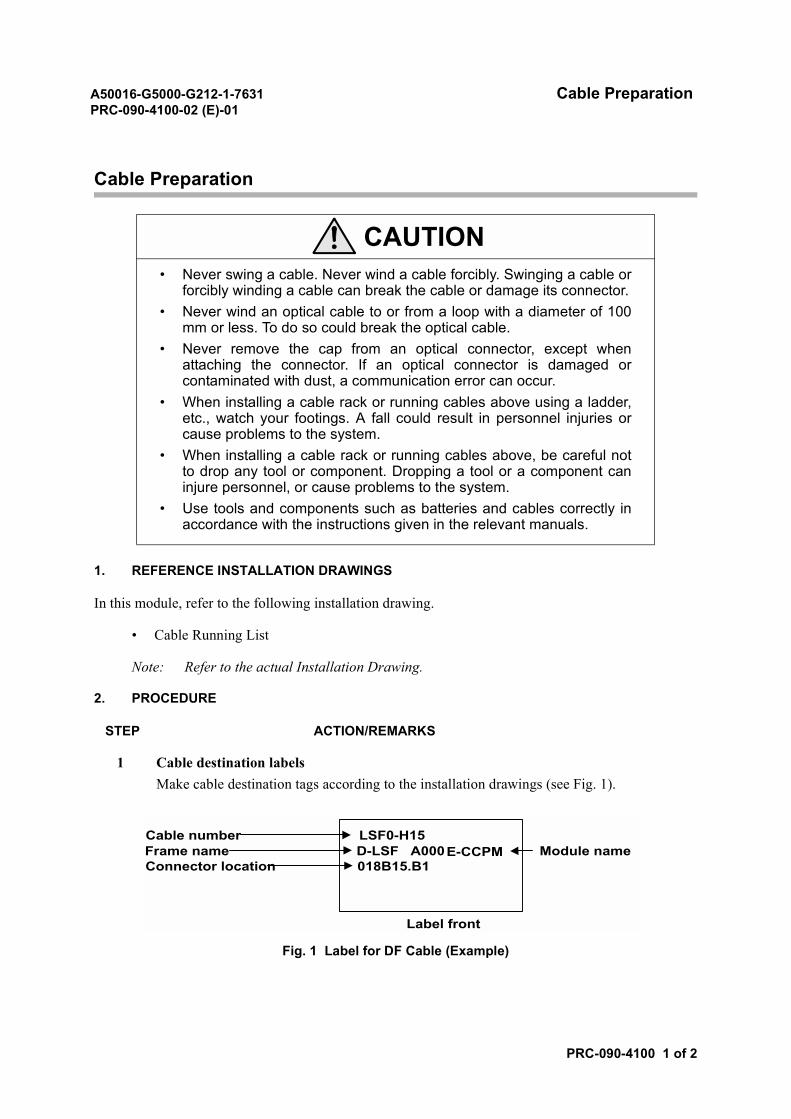
A50016-G5000-G212-1-7631 Cable PreparationPRC-090-4100-02 (E)-01
PRC-090-4100 1 of 2
Cable Preparation
1. REFERENCE INSTALLATION DRAWINGS
In this module, refer to the following installation drawing.
• Cable Running List
Note: Refer to the actual Installation Drawing.
2. PROCEDURE
STEP ACTION/REMARKS
1 Cable destination labelsMake cable destination tags according to the installation drawings (see Fig. 1).
Fig. 1 Label for DF Cable (Example)
CAUTION• Never swing a cable. Never wind a cable forcibly. Swinging a cable or
forcibly winding a cable can break the cable or damage its connector.• Never wind an optical cable to or from a loop with a diameter of 100
mm or less. To do so could break the optical cable.• Never remove the cap from an optical connector, except when
attaching the connector. If an optical connector is damaged orcontaminated with dust, a communication error can occur.
• When installing a cable rack or running cables above using a ladder,etc., watch your footings. A fall could result in personnel injuries orcause problems to the system.
• When installing a cable rack or running cables above, be careful notto drop any tool or component. Dropping a tool or a component caninjure personnel, or cause problems to the system.
• Use tools and components such as batteries and cables correctly inaccordance with the instructions given in the relevant manuals.
Cable numberFrame nameConnector location
Label front
LSF0-H15D-LSF A000018B15.B1
E-CCPM Module name
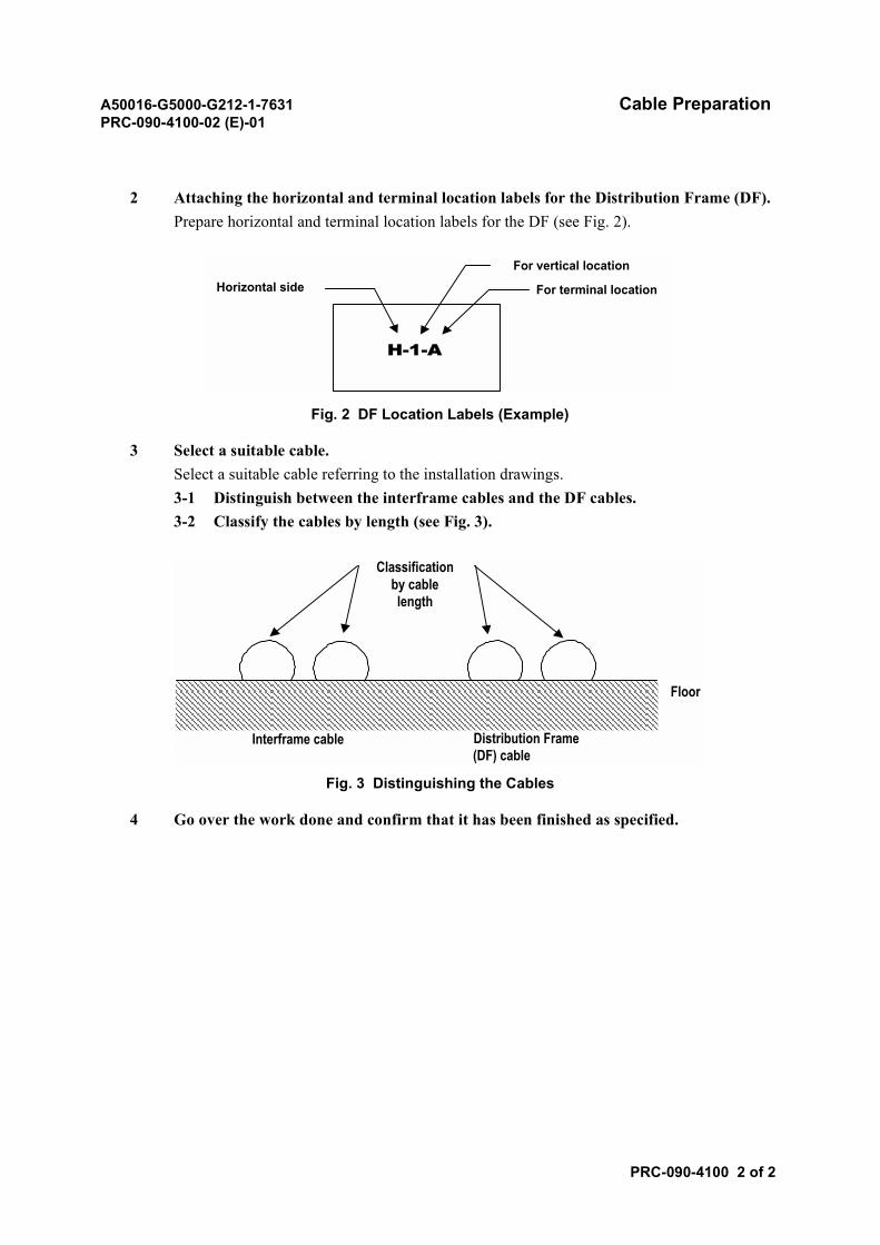
A50016-G5000-G212-1-7631 Cable PreparationPRC-090-4100-02 (E)-01
PRC-090-4100 2 of 2
2 Attaching the horizontal and terminal location labels for the Distribution Frame (DF).Prepare horizontal and terminal location labels for the DF (see Fig. 2).
Fig. 2 DF Location Labels (Example)
3 Select a suitable cable.Select a suitable cable referring to the installation drawings.3-1 Distinguish between the interframe cables and the DF cables.3-2 Classify the cables by length (see Fig. 3).
Fig. 3 Distinguishing the Cables
4 Go over the work done and confirm that it has been finished as specified.
Horizontal sideFor vertical location
For terminal location
H-1-A
Classificationby cablelength
Floor
Distribution Frame(DF) cable
Interframe cable
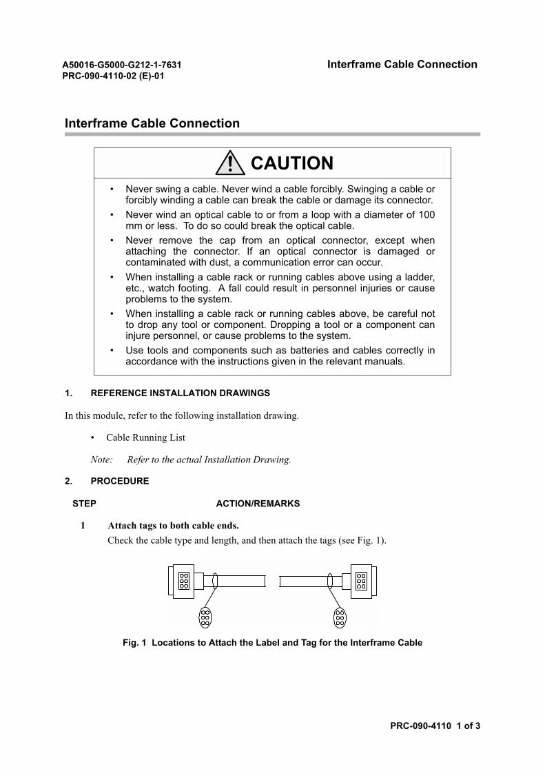
A50016-G5000-G212-1-7631 Interframe Cable ConnectionPRC-090-4110-02 (E)-01
PRC-090-4110 1 of 3
Interframe Cable Connection
1. REFERENCE INSTALLATION DRAWINGS
In this module, refer to the following installation drawing.
• Cable Running List
Note: Refer to the actual Installation Drawing.
2. PROCEDURE
STEP ACTION/REMARKS
1 Attach tags to both cable ends.Check the cable type and length, and then attach the tags (see Fig. 1).
Fig. 1 Locations to Attach the Label and Tag for the Interframe Cable
CAUTION• Never swing a cable. Never wind a cable forcibly. Swinging a cable or
forcibly winding a cable can break the cable or damage its connector.• Never wind an optical cable to or from a loop with a diameter of 100
mm or less. To do so could break the optical cable.• Never remove the cap from an optical connector, except when
attaching the connector. If an optical connector is damaged orcontaminated with dust, a communication error can occur.
• When installing a cable rack or running cables above using a ladder,etc., watch footing. A fall could result in personnel injuries or causeproblems to the system.
• When installing a cable rack or running cables above, be careful notto drop any tool or component. Dropping a tool or a component caninjure personnel, or cause problems to the system.
• Use tools and components such as batteries and cables correctly inaccordance with the instructions given in the relevant manuals.
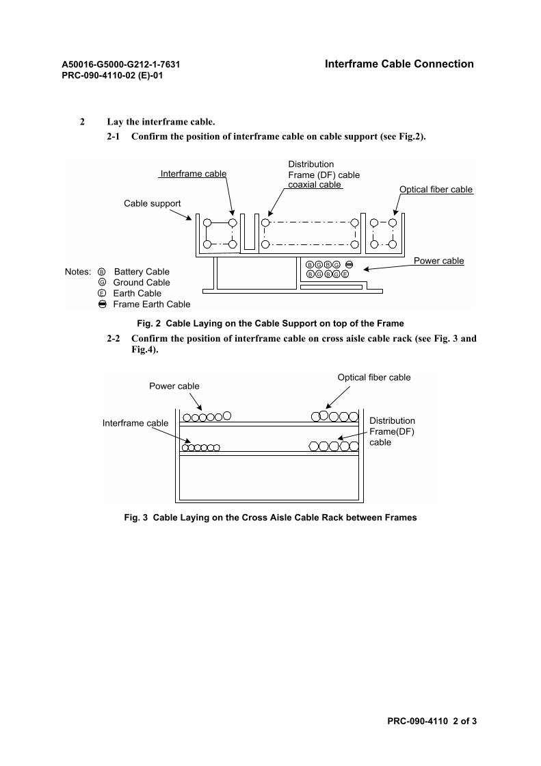
A50016-G5000-G212-1-7631 Interframe Cable ConnectionPRC-090-4110-02 (E)-01
PRC-090-4110 2 of 3
2 Lay the interframe cable.2-1 Confirm the position of interframe cable on cable support (see Fig.2).
Fig. 2 Cable Laying on the Cable Support on top of the Frame2-2 Confirm the position of interframe cable on cross aisle cable rack (see Fig. 3 and
Fig.4).
Fig. 3 Cable Laying on the Cross Aisle Cable Rack between Frames
Optical fiber cable
Power cable
DistributionFrame (DF) cablecoaxial cable
Interframe cable
Cable support
B
B B
B
G
G G
G ENotes: Battery Cable Ground Cable Earth Cable Frame Earth Cable
B
G
E
Optical fiber cablePower cable
Interframe cable DistributionFrame(DF)cable
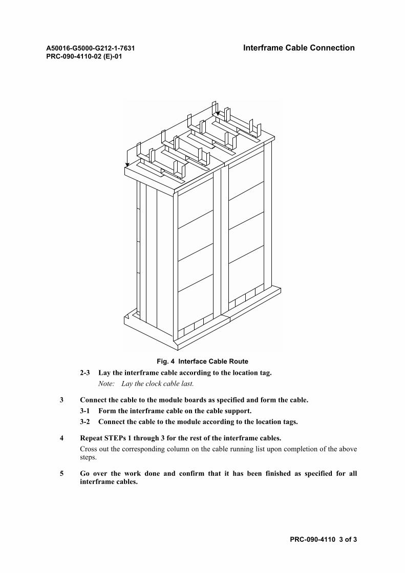
A50016-G5000-G212-1-7631 Interframe Cable ConnectionPRC-090-4110-02 (E)-01
PRC-090-4110 3 of 3
Fig. 4 Interface Cable Route2-3 Lay the interframe cable according to the location tag.
Note: Lay the clock cable last.
3 Connect the cable to the module boards as specified and form the cable.3-1 Form the interframe cable on the cable support.3-2 Connect the cable to the module according to the location tags.
4 Repeat STEPs 1 through 3 for the rest of the interframe cables.Cross out the corresponding column on the cable running list upon completion of the abovesteps.
5 Go over the work done and confirm that it has been finished as specified for allinterframe cables.
A50016-G5000-G212-1-7631 Optic Fiber Cable ConnectionPRC-090-4120-02 (E)-01
PRC-090-4120 1 of 2
Optic Fiber Cable Connection
1. REFERENCE INSTALLATION DRAWINGS
In this module, refer to the following installation drawing.
• Cable Running List
Note: Refer to the actual Installation Drawing.
CAUTION• Never swing a cable. Never wind a cable forcibly. Swinging a cable or
forcibly winding a cable can break the cable or damage its connector.• Never wind an optical cable to or from a loop with a diameter of 100
mm or less. To do so could break the optical cable.• Never remove the cap from an optical connector, except when
attaching the connector. If an optical connector is damaged orcontaminated with dust, a communication error can occur.
• When installing a cable rack or running cables above using a ladder,etc., watch your footing. A fall could result in personnel injuries orcause problems to the system.
• When installing a cable rack or running cables above, be careful notto drop any tool or component. Dropping a tool or a component caninjure personnel, or cause problems to the system.
• Use tools and components such as batteries and cables correctly inaccordance with the instructions given in the relevant manuals.
WARNINGHandling of Optic Fiber Cables• Take utmost care in laying and forming optic cables, since they are
vulnerable to tension, flexing, pressure and shock. (Flexing should bedone by securing a radius over: fiber cable with a diameter mm:=R30mm.)
• Use Tie-Wraps only on the outer cover or spiral tape of multi-conductor cables. Avoid applying them to any other part of the cables.
• Do not touch the tip of the connectors with your hands as the tips arevulnerable to dirt, dust, and other foreign matter.
• Plug in the connectors securely.
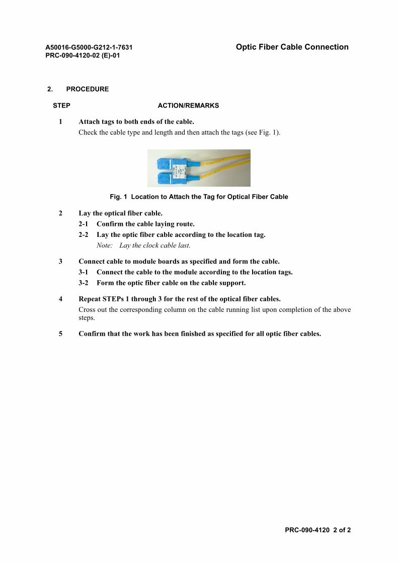
A50016-G5000-G212-1-7631 Optic Fiber Cable ConnectionPRC-090-4120-02 (E)-01
PRC-090-4120 2 of 2
2. PROCEDURE
STEP ACTION/REMARKS
1 Attach tags to both ends of the cable.Check the cable type and length and then attach the tags (see Fig. 1).
Fig. 1 Location to Attach the Tag for Optical Fiber Cable
2 Lay the optical fiber cable.2-1 Confirm the cable laying route.2-2 Lay the optic fiber cable according to the location tag.
Note: Lay the clock cable last.
3 Connect cable to module boards as specified and form the cable.3-1 Connect the cable to the module according to the location tags.3-2 Form the optic fiber cable on the cable support.
4 Repeat STEPs 1 through 3 for the rest of the optical fiber cables.Cross out the corresponding column on the cable running list upon completion of the abovesteps.
5 Confirm that the work has been finished as specified for all optic fiber cables.
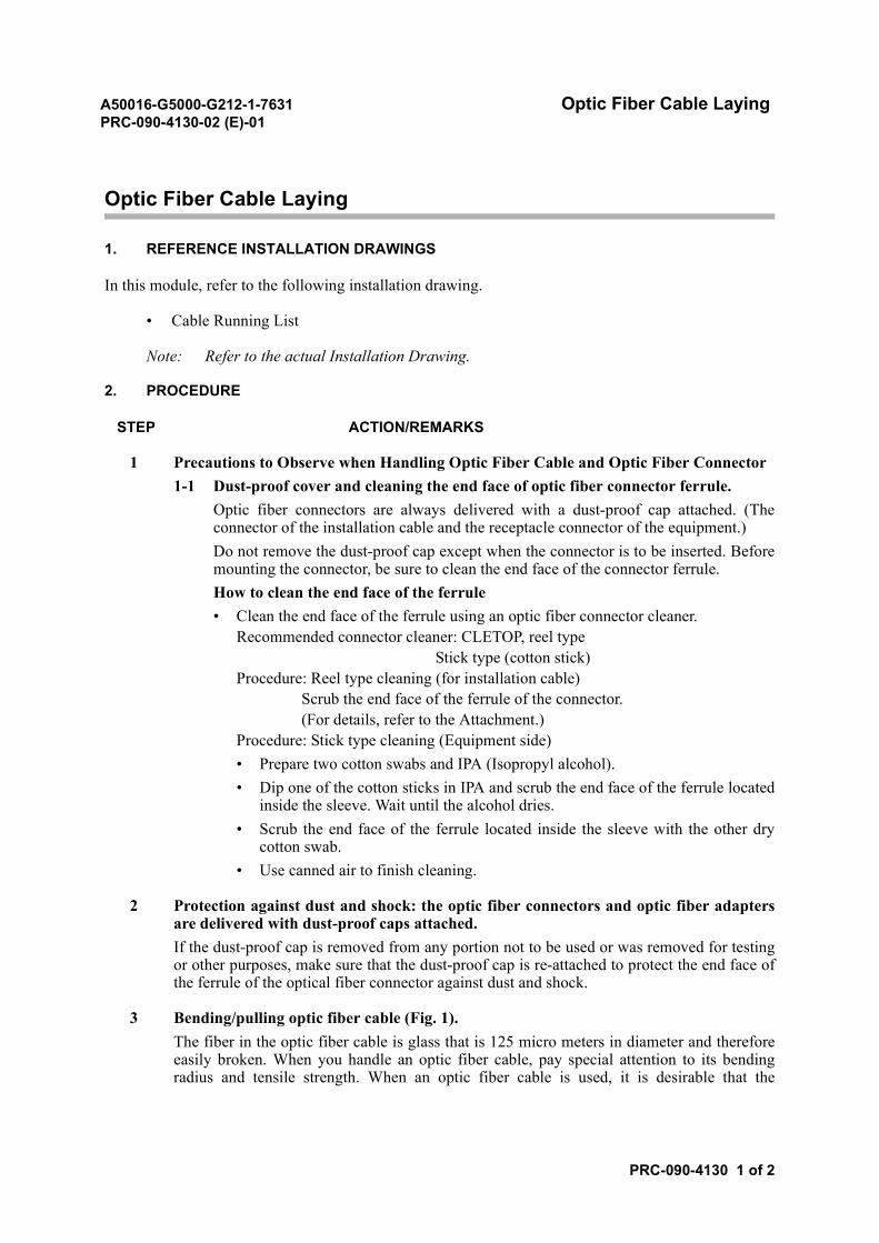
A50016-G5000-G212-1-7631 Optic Fiber Cable LayingPRC-090-4130-02 (E)-01
PRC-090-4130 1 of 2
Optic Fiber Cable Laying
1. REFERENCE INSTALLATION DRAWINGS
In this module, refer to the following installation drawing.
• Cable Running List
Note: Refer to the actual Installation Drawing.
2. PROCEDURE
STEP ACTION/REMARKS
1 Precautions to Observe when Handling Optic Fiber Cable and Optic Fiber Connector1-1 Dust-proof cover and cleaning the end face of optic fiber connector ferrule.
Optic fiber connectors are always delivered with a dust-proof cap attached. (Theconnector of the installation cable and the receptacle connector of the equipment.)Do not remove the dust-proof cap except when the connector is to be inserted. Beforemounting the connector, be sure to clean the end face of the connector ferrule.How to clean the end face of the ferrule• Clean the end face of the ferrule using an optic fiber connector cleaner.
Recommended connector cleaner: CLETOP, reel type Stick type (cotton stick)Procedure: Reel type cleaning (for installation cable) Scrub the end face of the ferrule of the connector. (For details, refer to the Attachment.)Procedure: Stick type cleaning (Equipment side)• Prepare two cotton swabs and IPA (Isopropyl alcohol).• Dip one of the cotton sticks in IPA and scrub the end face of the ferrule located
inside the sleeve. Wait until the alcohol dries.• Scrub the end face of the ferrule located inside the sleeve with the other dry
cotton swab.• Use canned air to finish cleaning.
2 Protection against dust and shock: the optic fiber connectors and optic fiber adaptersare delivered with dust-proof caps attached.If the dust-proof cap is removed from any portion not to be used or was removed for testingor other purposes, make sure that the dust-proof cap is re-attached to protect the end face ofthe ferrule of the optical fiber connector against dust and shock.
3 Bending/pulling optic fiber cable (Fig. 1).The fiber in the optic fiber cable is glass that is 125 micro meters in diameter and thereforeeasily broken. When you handle an optic fiber cable, pay special attention to its bendingradius and tensile strength. When an optic fiber cable is used, it is desirable that the
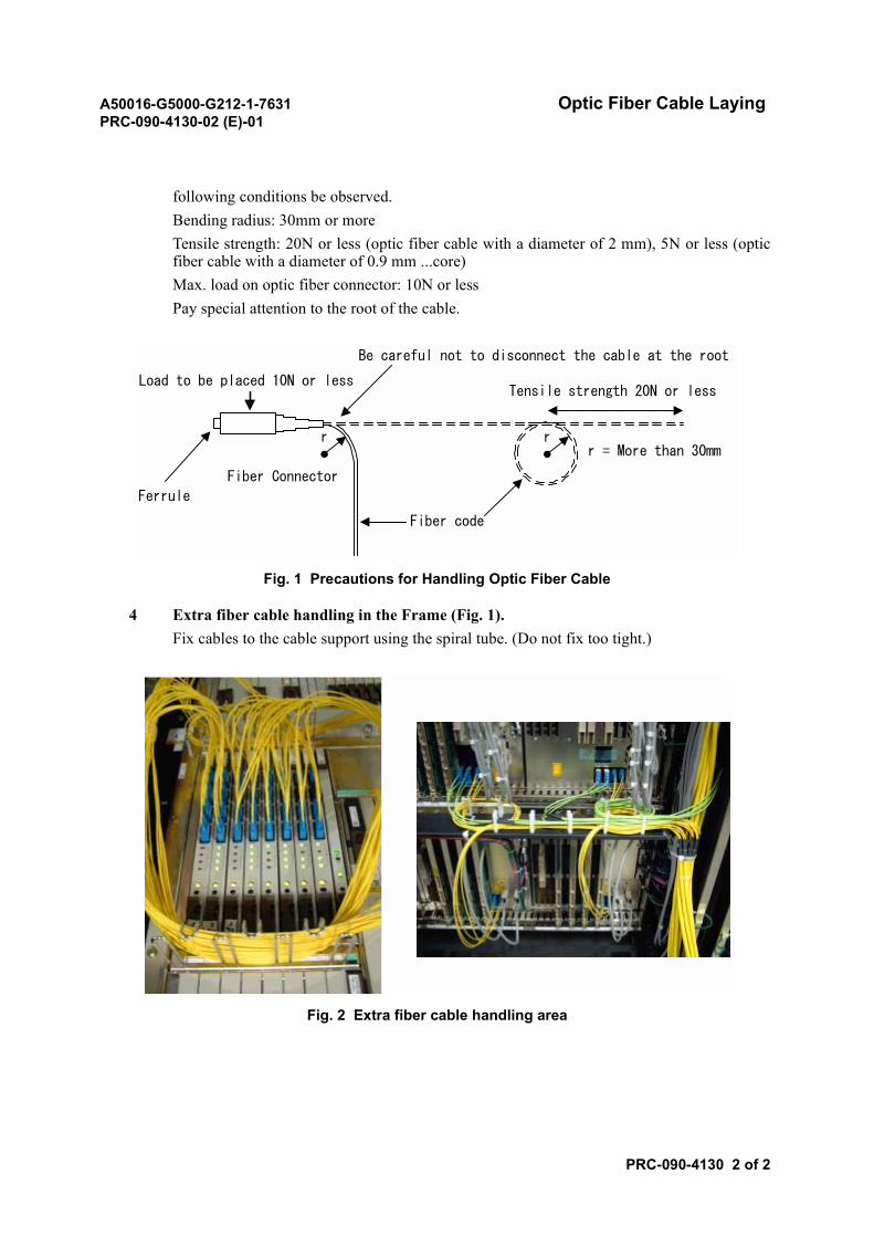
A50016-G5000-G212-1-7631 Optic Fiber Cable LayingPRC-090-4130-02 (E)-01
PRC-090-4130 2 of 2
following conditions be observed.Bending radius: 30mm or moreTensile strength: 20N or less (optic fiber cable with a diameter of 2 mm), 5N or less (opticfiber cable with a diameter of 0.9 mm ...core)Max. load on optic fiber connector: 10N or lessPay special attention to the root of the cable.
Fig. 1 Precautions for Handling Optic Fiber Cable
4 Extra fiber cable handling in the Frame (Fig. 1).Fix cables to the cable support using the spiral tube. (Do not fix too tight.)
Fig. 2 Extra fiber cable handling area
Fiber code
Fiber Connector
Ferrule
Load to be placed 10N or less
Be careful not to disconnect the cable at the root
Tensile strength 20N or less
rrr = More than 30mm
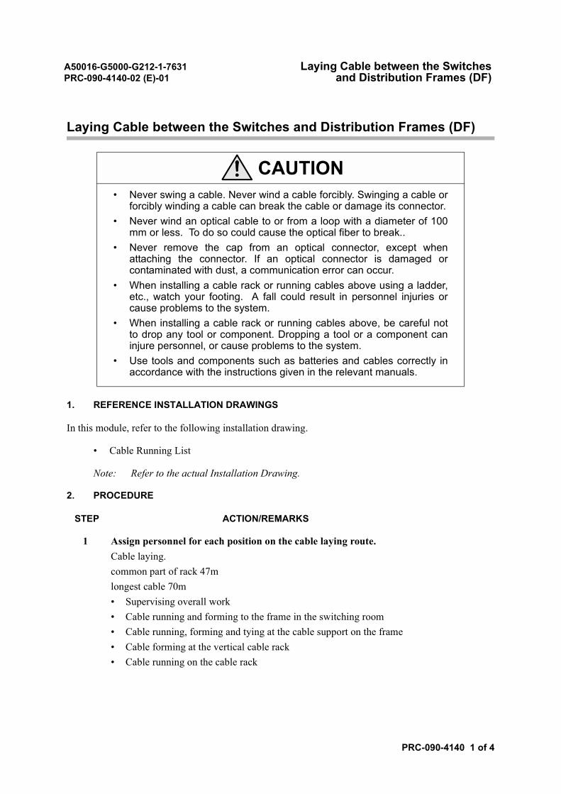
A50016-G5000-G212-1-7631 Laying Cable between the SwitchesPRC-090-4140-02 (E)-01 and Distribution Frames (DF)
PRC-090-4140 1 of 4
Laying Cable between the Switches and Distribution Frames (DF)
1. REFERENCE INSTALLATION DRAWINGS
In this module, refer to the following installation drawing.
• Cable Running List
Note: Refer to the actual Installation Drawing.
2. PROCEDURE
STEP ACTION/REMARKS
1 Assign personnel for each position on the cable laying route.Cable laying.common part of rack 47mlongest cable 70m• Supervising overall work• Cable running and forming to the frame in the switching room• Cable running, forming and tying at the cable support on the frame• Cable forming at the vertical cable rack• Cable running on the cable rack
CAUTION• Never swing a cable. Never wind a cable forcibly. Swinging a cable or
forcibly winding a cable can break the cable or damage its connector.• Never wind an optical cable to or from a loop with a diameter of 100
mm or less. To do so could cause the optical fiber to break..• Never remove the cap from an optical connector, except when
attaching the connector. If an optical connector is damaged orcontaminated with dust, a communication error can occur.
• When installing a cable rack or running cables above using a ladder,etc., watch your footing. A fall could result in personnel injuries orcause problems to the system.
• When installing a cable rack or running cables above, be careful notto drop any tool or component. Dropping a tool or a component caninjure personnel, or cause problems to the system.
• Use tools and components such as batteries and cables correctly inaccordance with the instructions given in the relevant manuals.
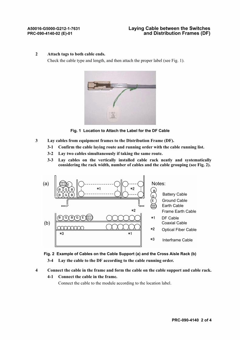
A50016-G5000-G212-1-7631 Laying Cable between the SwitchesPRC-090-4140-02 (E)-01 and Distribution Frames (DF)
PRC-090-4140 2 of 4
2 Attach tags to both cable ends.Check the cable type and length, and then attach the proper label (see Fig. 1).
Fig. 1 Location to Attach the Label for the DF Cable
3 Lay cables from equipment frames to the Distribution Frame (DF).3-1 Confirm the cable laying route and running order with the cable running list.3-2 Lay two cables simultaneously if taking the same route.3-3 Lay cables on the vertically installed cable rack neatly and systematically
considering the rack width, number of cables and the cable grouping (see Fig. 2).
Fig. 2 Example of Cables on the Cable Support (a) and the Cross Aisle Rack (b)3-4 Lay the cable to the DF according to the cable running order.
4 Connect the cable in the frame and form the cable on the cable support and cable rack.4-1 Connect the cable in the frame.
Connect the cable to the module according to the location label.
GB GB E
GB B
GB B
*1 *2
*1
*2
*3
E
B
G
E
(a)
(b)*1
Notes:
Battery CableGround CableEarth CableFrame Earth CableDF CableCoaxial Cable
*2 Optical Fiber Cable
*3 Interframe Cable
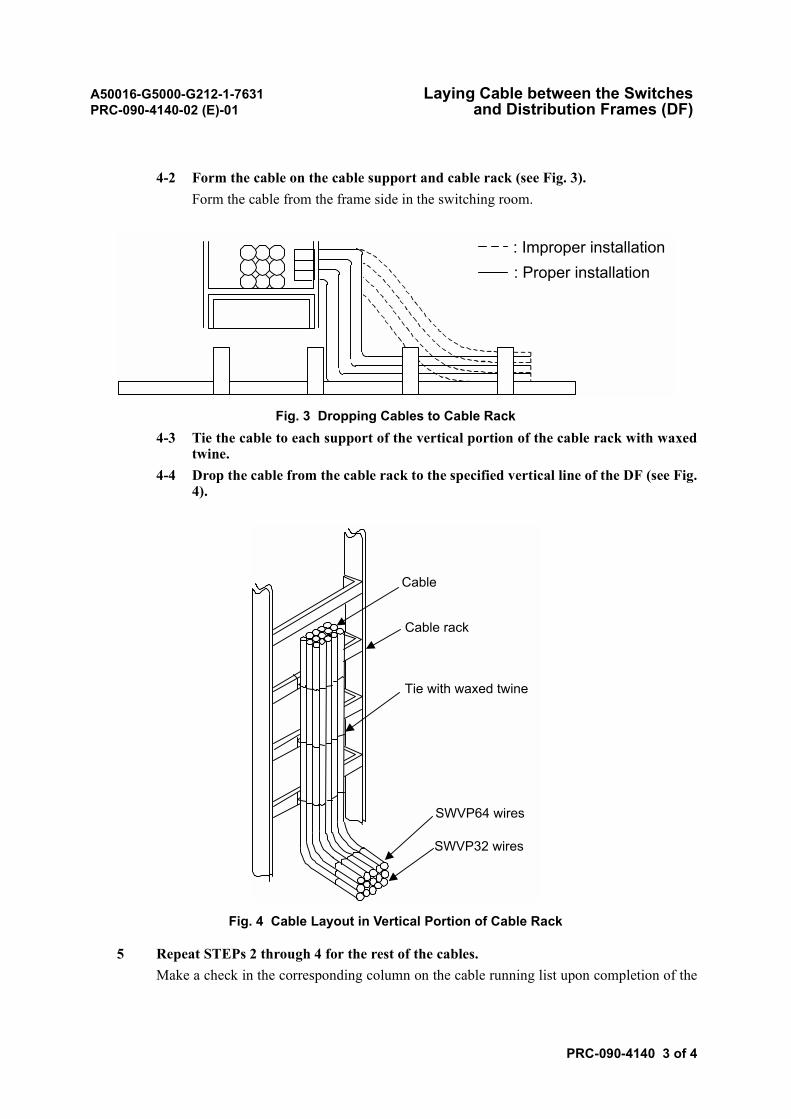
A50016-G5000-G212-1-7631 Laying Cable between the SwitchesPRC-090-4140-02 (E)-01 and Distribution Frames (DF)
PRC-090-4140 3 of 4
4-2 Form the cable on the cable support and cable rack (see Fig. 3).Form the cable from the frame side in the switching room.
Fig. 3 Dropping Cables to Cable Rack4-3 Tie the cable to each support of the vertical portion of the cable rack with waxed
twine.4-4 Drop the cable from the cable rack to the specified vertical line of the DF (see Fig.
4).
Fig. 4 Cable Layout in Vertical Portion of Cable Rack
5 Repeat STEPs 2 through 4 for the rest of the cables.Make a check in the corresponding column on the cable running list upon completion of the
vv
vv
: Improper installation: Proper installation
Cable
Cable rack
Tie with waxed twine
SWVP64 wires
SWVP32 wires
A50016-G5000-G212-1-7631 Laying Cable between the SwitchesPRC-090-4140-02 (E)-01 and Distribution Frames (DF)
PRC-090-4140 4 of 4
above steps.
6 Confirm that the work has been finished as specified for all the DF cables.
7 Lay the miscellaneous and signal cables.7-1 Lay the miscellaneous (MISC) cable and Audible Alarm Panel (AALP), Visual
Alarm Panel (VALP) cable and the power room alarm cable, etc (make sure toseparate the miscellaneous and signal cables from the DF cables).
7-2 Attach the tags to both ends of the cable.7-3 Form the cable on the cable support and cable rack.7-4 Strap cables to the vertical portion of the cable rack using waxed twine.
For the vertical portion of the cable rack, strap cables to each support.
8 Go over the work done and confirm that it has been finished as specified.
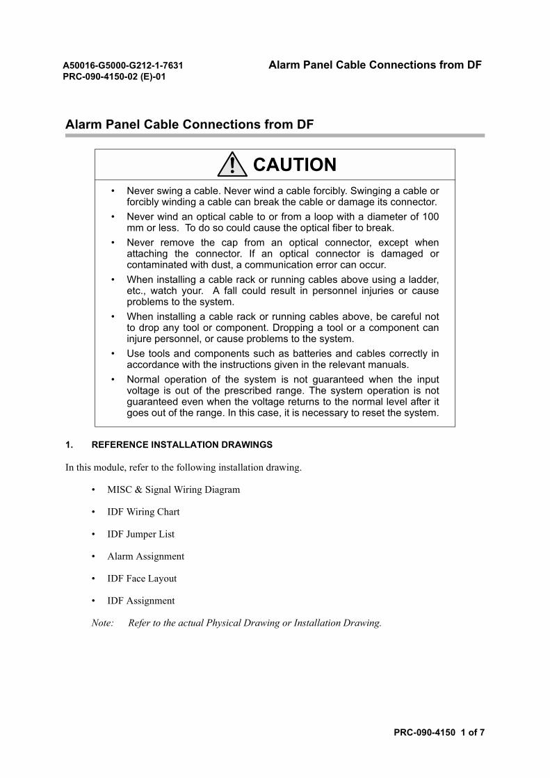
A50016-G5000-G212-1-7631 Alarm Panel Cable Connections from DFPRC-090-4150-02 (E)-01
PRC-090-4150 1 of 7
Alarm Panel Cable Connections from DF
1. REFERENCE INSTALLATION DRAWINGS
In this module, refer to the following installation drawing.
• MISC & Signal Wiring Diagram
• IDF Wiring Chart
• IDF Jumper List
• Alarm Assignment
• IDF Face Layout
• IDF Assignment
Note: Refer to the actual Physical Drawing or Installation Drawing.
CAUTION• Never swing a cable. Never wind a cable forcibly. Swinging a cable or
forcibly winding a cable can break the cable or damage its connector.• Never wind an optical cable to or from a loop with a diameter of 100
mm or less. To do so could cause the optical fiber to break.• Never remove the cap from an optical connector, except when
attaching the connector. If an optical connector is damaged orcontaminated with dust, a communication error can occur.
• When installing a cable rack or running cables above using a ladder,etc., watch your. A fall could result in personnel injuries or causeproblems to the system.
• When installing a cable rack or running cables above, be careful notto drop any tool or component. Dropping a tool or a component caninjure personnel, or cause problems to the system.
• Use tools and components such as batteries and cables correctly inaccordance with the instructions given in the relevant manuals.
• Normal operation of the system is not guaranteed when the inputvoltage is out of the prescribed range. The system operation is notguaranteed even when the voltage returns to the normal level after itgoes out of the range. In this case, it is necessary to reset the system.
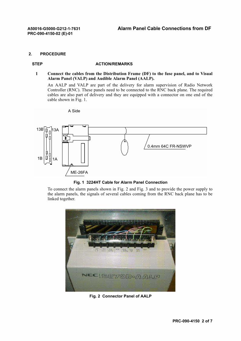
A50016-G5000-G212-1-7631 Alarm Panel Cable Connections from DFPRC-090-4150-02 (E)-01
PRC-090-4150 2 of 7
2. PROCEDURE
STEP ACTION/REMARKS
1 Connect the cables from the Distribution Frame (DF) to the fuse panel, and to VisualAlarm Panel (VALP) and Audible Alarm Panel (AALP).An AALP and VALP are part of the delivery for alarm supervision of Radio NetworkController (RNC). These panels need to be connected to the RNC back plane. The requiredcables are also part of delivery and they are equipped with a connector on one end of thecable shown in Fig. 1.
Fig. 1 3224HT Cable for Alarm Panel ConnectionTo connect the alarm panels shown in Fig. 2 and Fig. 3 and to provide the power supply tothe alarm panels, the signals of several cables coming from the RNC back plane has to belinked together.
Fig. 2 Connector Panel of AALP
A Side
13B 13A
1A1B
ME-26FA
0.4mm 64C FR-NSWVP
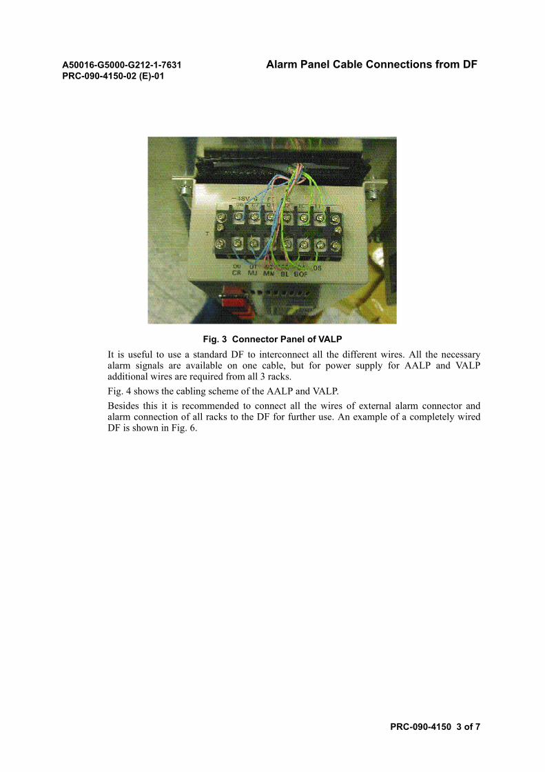
A50016-G5000-G212-1-7631 Alarm Panel Cable Connections from DFPRC-090-4150-02 (E)-01
PRC-090-4150 3 of 7
Fig. 3 Connector Panel of VALPIt is useful to use a standard DF to interconnect all the different wires. All the necessaryalarm signals are available on one cable, but for power supply for AALP and VALPadditional wires are required from all 3 racks.Fig. 4 shows the cabling scheme of the AALP and VALP.Besides this it is recommended to connect all the wires of external alarm connector andalarm connection of all racks to the DF for further use. An example of a completely wiredDF is shown in Fig. 6.
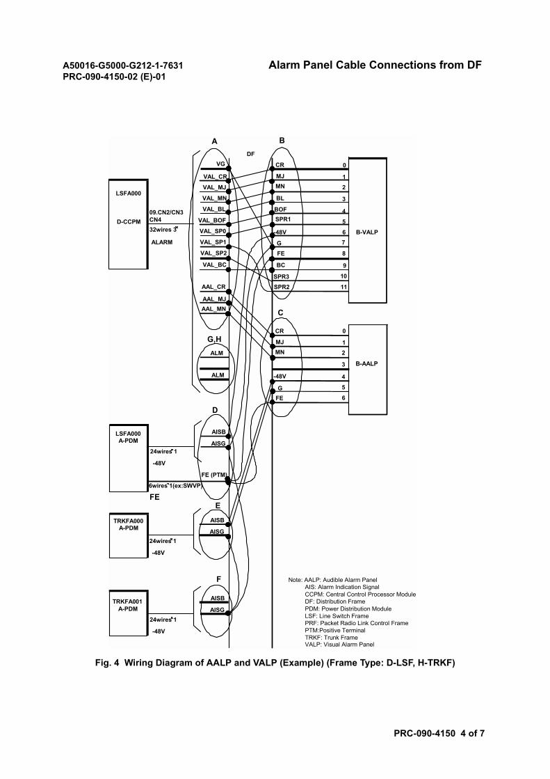
A50016-G5000-G212-1-7631 Alarm Panel Cable Connections from DFPRC-090-4150-02 (E)-01
PRC-090-4150 4 of 7
Fig. 4 Wiring Diagram of AALP and VALP (Example) (Frame Type: D-LSF, H-TRKF)
AISG
AISB
AISG
AISB
AISG
AISB
FE (PTM)
EFE
TRKFA001A-PDM
TRKFA000A-PDM
LSFA000A-PDM
LSFA000
D-CCPM
BA
09.CN2/CN3CN432wires 3
ALARM
24wires 1
6wires 1(ex:SWVP)
-48V
24wires 1
-48V
24wires 1
-48V
C
D
F
G,H
FEG
-48V
MNMJ
CR
6
5
4
3
21
0
6
5
4
3
21
0
7
8
9
10
11
MNMJ
CR
SPR1BOF
BL
-48V
GFE
BC
SPR3SPR2
B-VALP
B-AALP
DFVG
VAL_CR
VAL_MJ
VAL_MN
VAL_BL
VAL_BOF
VAL_SP0
VAL_SP1
VAL_BC
VAL_SP2
AAL_CR
AAL_MJAAL_MN
ALM
ALM
Note: AALP: Audible Alarm Panel AIS: Alarm Indication Signal CCPM: Central Control Processor Module DF: Distribution Frame PDM: Power Distribution Module LSF: Line Switch Frame PRF: Packet Radio Link Control Frame PTM:Positive Terminal TRKF: Trunk Frame VALP: Visual Alarm Panel
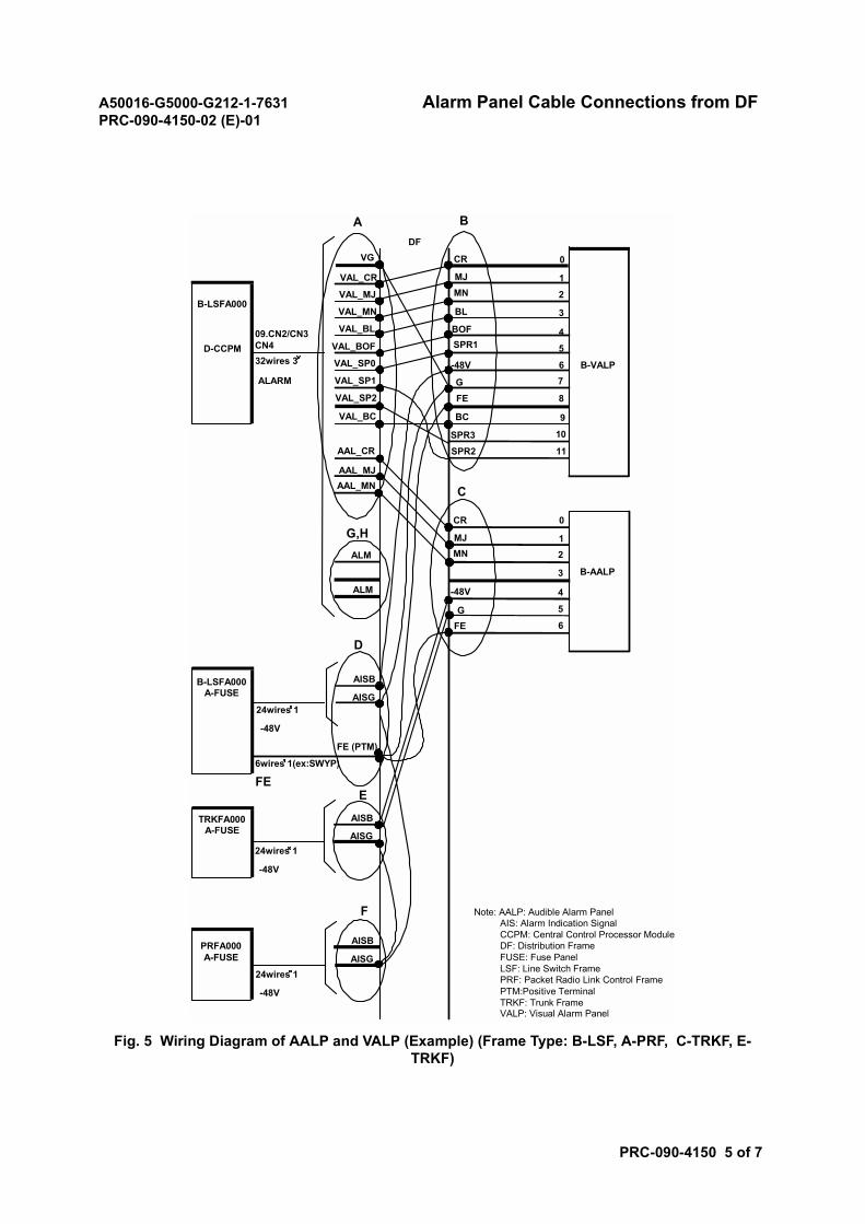
A50016-G5000-G212-1-7631 Alarm Panel Cable Connections from DFPRC-090-4150-02 (E)-01
PRC-090-4150 5 of 7
Fig. 5 Wiring Diagram of AALP and VALP (Example) (Frame Type: B-LSF, A-PRF, C-TRKF, E-TRKF)
AISG
AISB
AISG
AISB
AISG
AISB
FE (PTM)
EFE
PRFA000A-FUSE
TRKFA000A-FUSE
B-LSFA000A-FUSE
B-LSFA000
D-CCPM
BA
09.CN2/CN3CN432wires 3
ALARM
24wires 1
6wires 1(ex:SWYP)
-48V
24wires 1
-48V
24wires 1
-48V
C
D
F
G,H
FEG
-48V
MNMJ
CR
6
5
4
3
21
0
6
5
4
3
2
1
0
7
8
9
10
11
MNMJ
CR
SPR1BOF
BL
-48V
GFE
BC
SPR3SPR2
B-VALP
B-AALP
DFVG
VAL_CR
VAL_MJ
VAL_MN
VAL_BL
VAL_BOF
VAL_SP0
VAL_SP1
VAL_BC
VAL_SP2
AAL_CR
AAL_MJAAL_MN
ALM
ALM
Note: AALP: Audible Alarm Panel AIS: Alarm Indication Signal CCPM: Central Control Processor Module DF: Distribution Frame FUSE: Fuse Panel LSF: Line Switch Frame PRF: Packet Radio Link Control Frame PTM:Positive Terminal TRKF: Trunk Frame VALP: Visual Alarm Panel
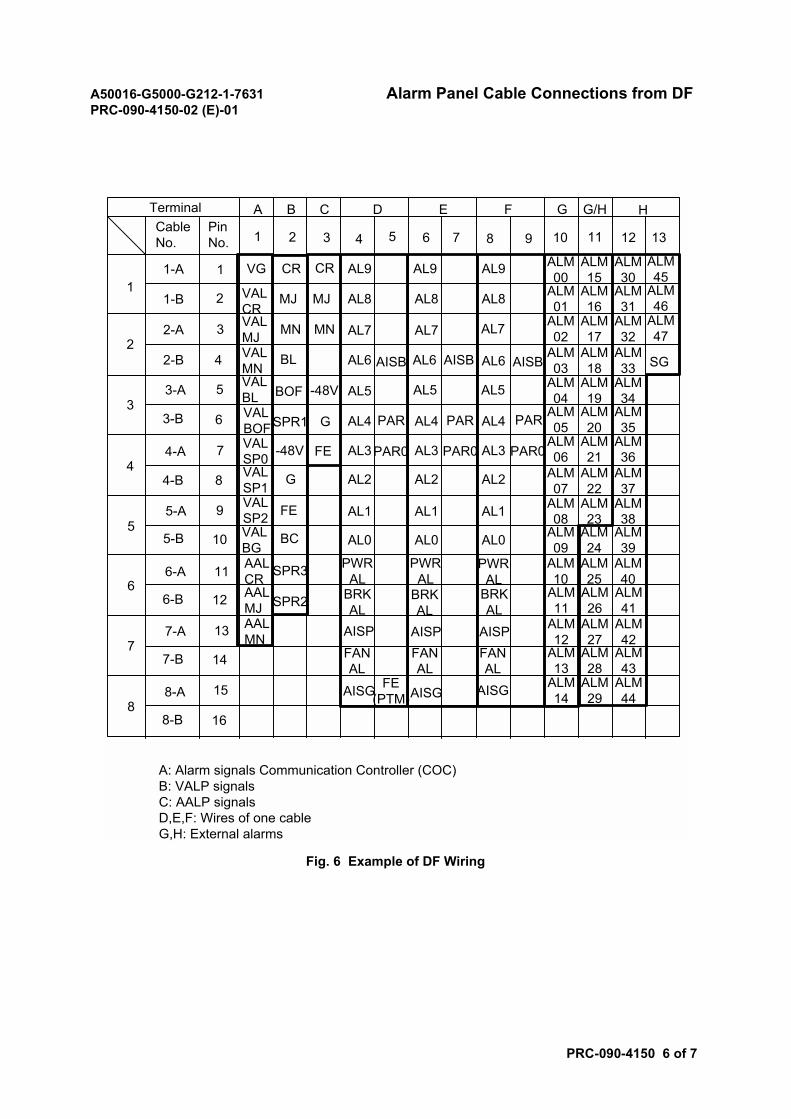
A50016-G5000-G212-1-7631 Alarm Panel Cable Connections from DFPRC-090-4150-02 (E)-01
PRC-090-4150 6 of 7
Fig. 6 Example of DF Wiring
Terminal A B C D E F G G/H H
1
2
3
4
5
6
7
8
CableNo.
PinNo. 1 2 3 4 5 6 7 8 9 10 11 12 13
1-A 1
1-B 2
2-A
2-B
3
4
3-A
3-B
4-A
4-B
5-A
5-B
6-A
6-B
7-A
7-B
8-A
8-B
5
6
7
8
9
10
11
12
13
14
15
16
VG
VALCRVALMJVALMNVALBLVALBOFVALSP0VALSP1VALSP2VALBGAALCRAALMJAALMN
CR CR
MJ MJ
MNMN
BL
BOF
SPR1
-48V
FE
G
BC
SPR3
SPR2
AL9 AL9 AL9
AL8 AL8AL8
AL7 AL7 AL7
AL6 AL6 AL6
AL5 AL5 AL5
AISB AISB AISB
-48V
AL4
AL3
AL2
AL1
AL0
AL4
AL3
AL2
AL1
AL0
AL4
AL3
AL2
AL1
AL0
G
FE
ALM00
ALM01
ALM02
ALM03
ALM04
ALM05
ALM06
ALM07
ALM08
ALM09
ALM10
ALM11
ALM12
ALM13
ALM14
ALM15
ALM16
ALM17
ALM18
ALM19
ALM20
ALM21
ALM22
ALM23
ALM24
ALM25
ALM26
ALM27
ALM28
ALM29
ALM30
ALM31
ALM32
ALM33
ALM34
ALM35
ALM36
ALM37
ALM38
ALM39
ALM40
ALM41
ALM42
ALM43
ALM44
ALM45
ALM46
ALM47
SG
PWRAL
PWRAL
PWRAL
BRKAL
BRKAL
BRKAL
AISP AISP AISP
AISGAISGAISG
FANAL
FANAL
FANAL
FE(PTM)
A: Alarm signals Communication Controller (COC)B: VALP signalsC: AALP signalsD,E,F: Wires of one cableG,H: External alarms
PAR PAR PAR
PAR0 PAR0 PAR0
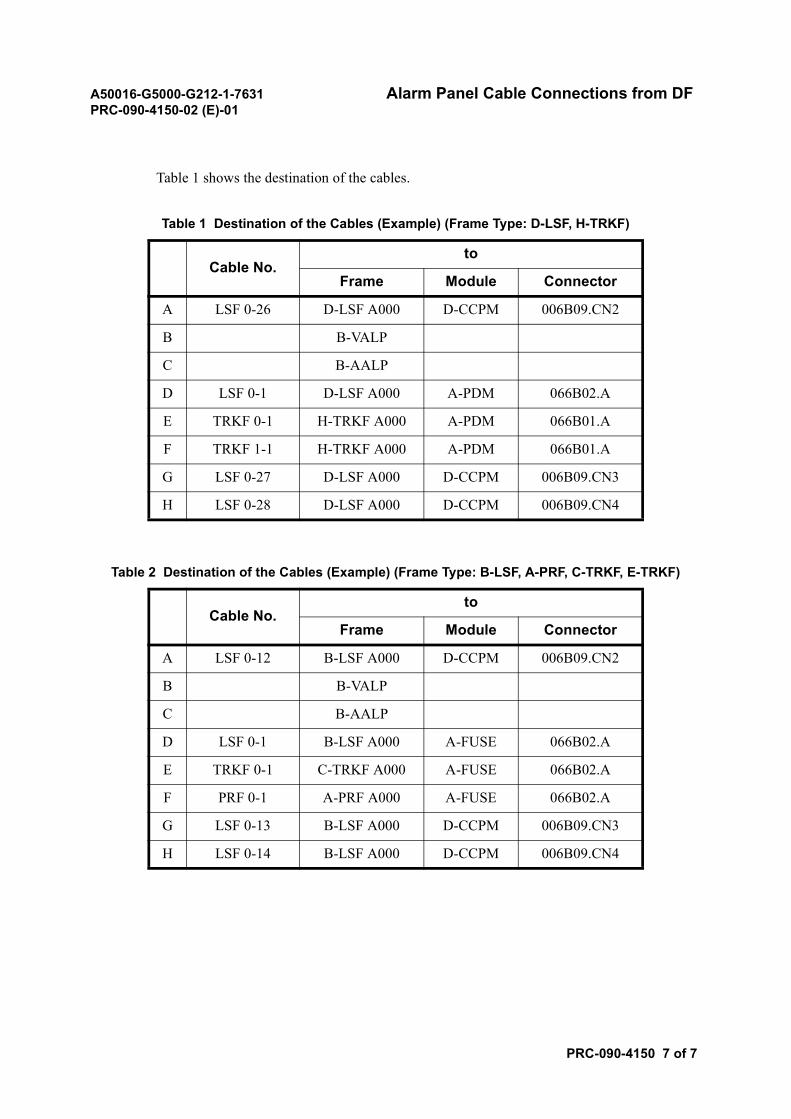
A50016-G5000-G212-1-7631 Alarm Panel Cable Connections from DFPRC-090-4150-02 (E)-01
PRC-090-4150 7 of 7
Table 1 shows the destination of the cables.
Table 1 Destination of the Cables (Example) (Frame Type: D-LSF, H-TRKF)
Cable No.to
Frame Module Connector
A LSF 0-26 D-LSF A000 D-CCPM 006B09.CN2
B B-VALP
C B-AALP
D LSF 0-1 D-LSF A000 A-PDM 066B02.A
E TRKF 0-1 H-TRKF A000 A-PDM 066B01.A
F TRKF 1-1 H-TRKF A000 A-PDM 066B01.A
G LSF 0-27 D-LSF A000 D-CCPM 006B09.CN3
H LSF 0-28 D-LSF A000 D-CCPM 006B09.CN4
Table 2 Destination of the Cables (Example) (Frame Type: B-LSF, A-PRF, C-TRKF, E-TRKF)
Cable No.to
Frame Module Connector
A LSF 0-12 B-LSF A000 D-CCPM 006B09.CN2
B B-VALP
C B-AALP
D LSF 0-1 B-LSF A000 A-FUSE 066B02.A
E TRKF 0-1 C-TRKF A000 A-FUSE 066B02.A
F PRF 0-1 A-PRF A000 A-FUSE 066B02.A
G LSF 0-13 B-LSF A000 D-CCPM 006B09.CN3
H LSF 0-14 B-LSF A000 D-CCPM 006B09.CN4
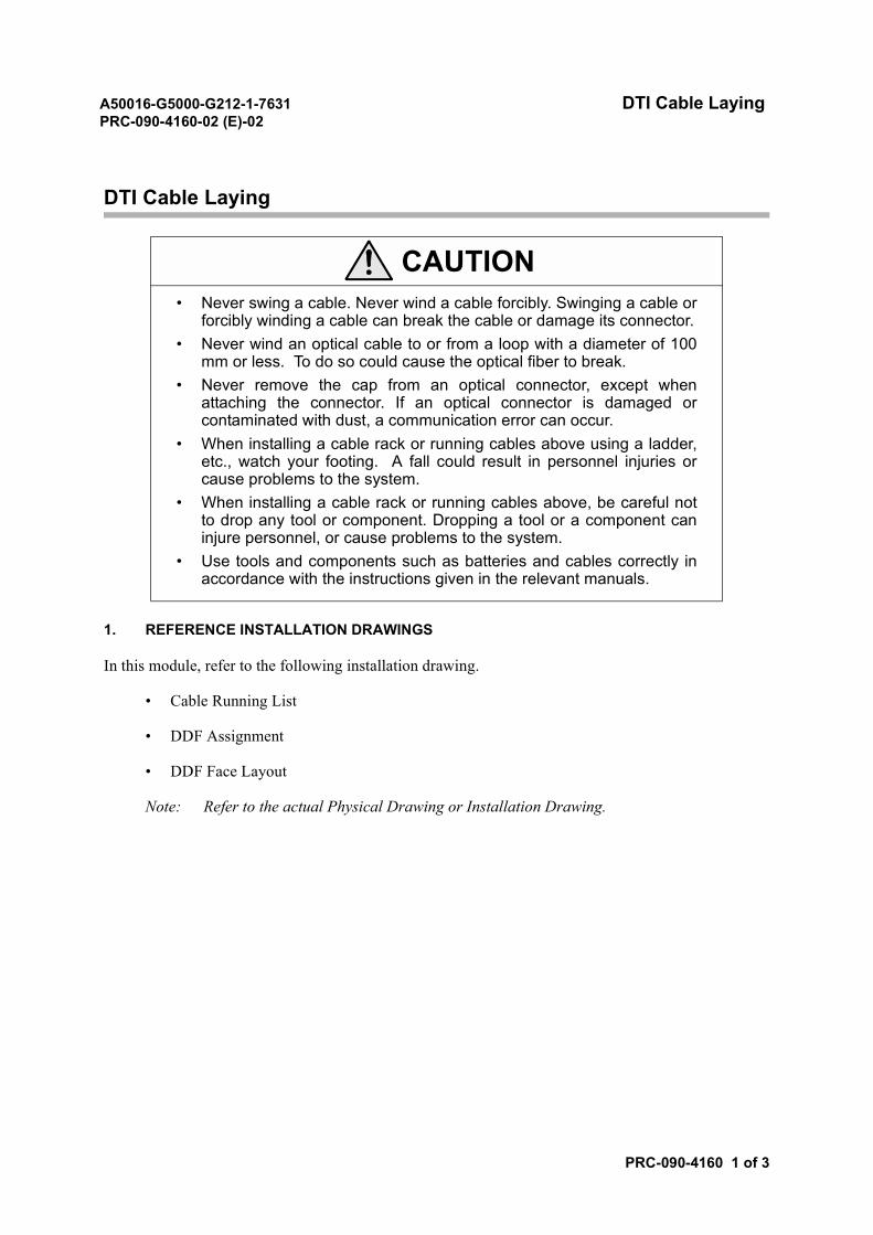
A50016-G5000-G212-1-7631 DTI Cable LayingPRC-090-4160-02 (E)-02
PRC-090-4160 1 of 3
DTI Cable Laying
1. REFERENCE INSTALLATION DRAWINGS
In this module, refer to the following installation drawing.
• Cable Running List
• DDF Assignment
• DDF Face Layout
Note: Refer to the actual Physical Drawing or Installation Drawing.
CAUTION• Never swing a cable. Never wind a cable forcibly. Swinging a cable or
forcibly winding a cable can break the cable or damage its connector.• Never wind an optical cable to or from a loop with a diameter of 100
mm or less. To do so could cause the optical fiber to break.• Never remove the cap from an optical connector, except when
attaching the connector. If an optical connector is damaged orcontaminated with dust, a communication error can occur.
• When installing a cable rack or running cables above using a ladder,etc., watch your footing. A fall could result in personnel injuries orcause problems to the system.
• When installing a cable rack or running cables above, be careful notto drop any tool or component. Dropping a tool or a component caninjure personnel, or cause problems to the system.
• Use tools and components such as batteries and cables correctly inaccordance with the instructions given in the relevant manuals.
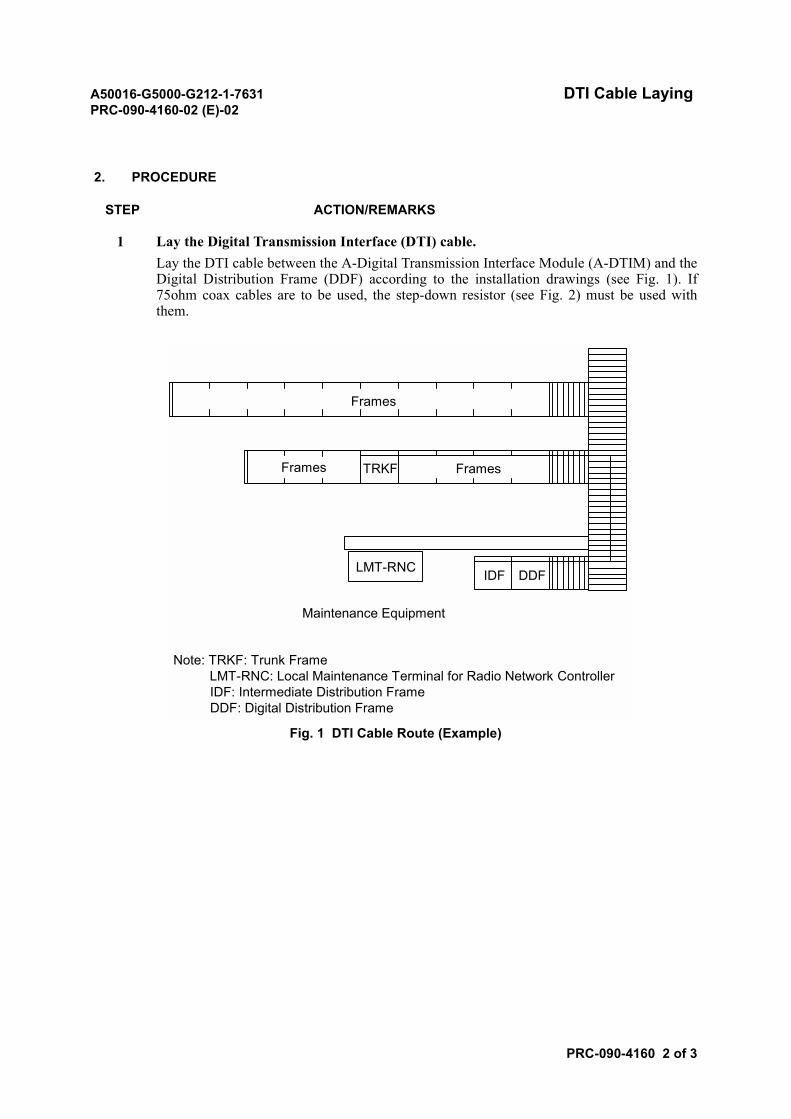
A50016-G5000-G212-1-7631 DTI Cable LayingPRC-090-4160-02 (E)-02
PRC-090-4160 2 of 3
2. PROCEDURE
STEP ACTION/REMARKS
1 Lay the Digital Transmission Interface (DTI) cable.Lay the DTI cable between the A-Digital Transmission Interface Module (A-DTIM) and theDigital Distribution Frame (DDF) according to the installation drawings (see Fig. 1). If75ohm coax cables are to be used, the step-down resistor (see Fig. 2) must be used withthem.
Fig. 1 DTI Cable Route (Example)
Frames
Frames TRKF Frames
LMT-RNC IDF DDF
Maintenance Equipment
Note: TRKF: Trunk Frame LMT-RNC: Local Maintenance Terminal for Radio Network Controller
IDF: Intermediate Distribution Frame DDF: Digital Distribution Frame
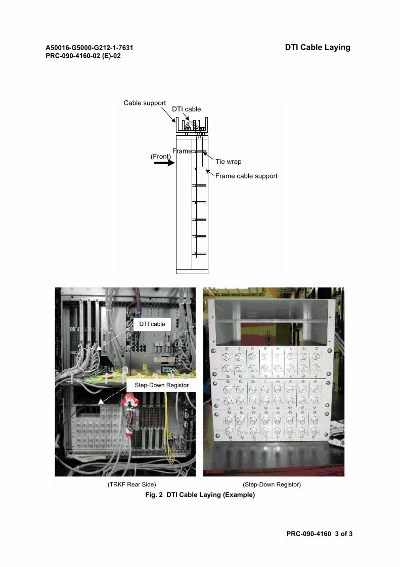
A50016-G5000-G212-1-7631 DTI Cable LayingPRC-090-4160-02 (E)-02
PRC-090-4160 3 of 3
Fig. 2 DTI Cable Laying (Example)
Cable supportDTI cable
Frame cable support
Tie wrapFrame
(Front)
DTI cable
Step-Down Registor
(TRKF Rear Side) (Step-Down Registor)
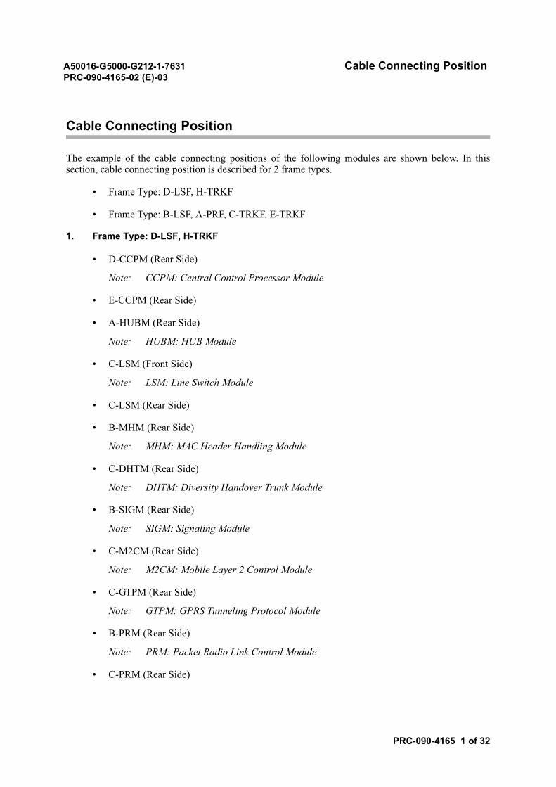
A50016-G5000-G212-1-7631 Cable Connecting PositionPRC-090-4165-02 (E)-03
PRC-090-4165 1 of 32
Cable Connecting Position
The example of the cable connecting positions of the following modules are shown below. In thissection, cable connecting position is described for 2 frame types.
• Frame Type: D-LSF, H-TRKF
• Frame Type: B-LSF, A-PRF, C-TRKF, E-TRKF
1. Frame Type: D-LSF, H-TRKF
• D-CCPM (Rear Side)
Note: CCPM: Central Control Processor Module
• E-CCPM (Rear Side)
• A-HUBM (Rear Side)
Note: HUBM: HUB Module
• C-LSM (Front Side)
Note: LSM: Line Switch Module
• C-LSM (Rear Side)
• B-MHM (Rear Side)
Note: MHM: MAC Header Handling Module
• C-DHTM (Rear Side)
Note: DHTM: Diversity Handover Trunk Module
• B-SIGM (Rear Side)
Note: SIGM: Signaling Module
• C-M2CM (Rear Side)
Note: M2CM: Mobile Layer 2 Control Module
• C-GTPM (Rear Side)
Note: GTPM: GPRS Tunneling Protocol Module
• B-PRM (Rear Side)
Note: PRM: Packet Radio Link Control Module
• C-PRM (Rear Side)

A50016-G5000-G212-1-7631 Cable Connecting PositionPRC-090-4165-02 (E)-03
PRC-090-4165 2 of 32
• A-DTIM (Rear Side)
Note: DTIM: Digital Transmission Interface Module
• A-PDM (Rear Side)
Note: PDM: PowerDistribution Module
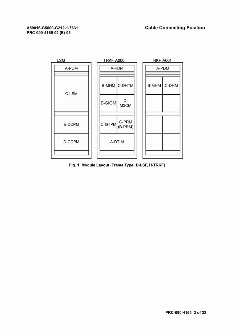
A50016-G5000-G212-1-7631 Cable Connecting PositionPRC-090-4165-02 (E)-03
PRC-090-4165 3 of 32
Fig. 1 Module Layout (Frame Type: D-LSF, H-TRKF)
LSM TRKF A000 TRKF A001
A-PDM
C-LSM
E-CCPM
A-PDM
B-MHM C-DHTM
B-SIGM C-M2CM
C-GTPM
D-CCPM
C-PRM(B-PRM)
A-DTIM
A-PDM
B-MHM C-DHM
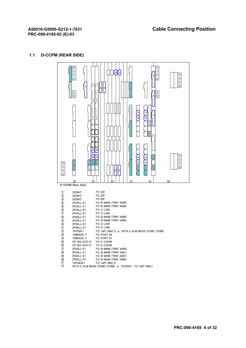
A50016-G5000-G212-1-7631 Cable Connecting PositionPRC-090-4165-02 (E)-03
PRC-090-4165 4 of 32
1.1 D-CCPM (REAR SIDE)
30 25 20 15 10 05D-CCPM (Rear Side)
⑯ ⑮
⑭ ⑬
⑫
④
⑤
⑧
⑨
①
②
⑰⑲
③
⑥
⑦
⑩
⑪
⑱⑳
21
22
① 3224HT TO: IDF
② 3224HT TO: IDF
③ 3224HT TO: IDF
④ 2P24LL-E1 TO: B-MHM (TRKF A000)
⑤ 2P24LL-E1 TO: B-MHM (TRKF A000)
⑥ 2P24LL-E1 TO: C-LSM
⑦ 2P24LL-E1 TO: C-LSM
⑧ 2P24LL-E1 TO: B-MHM (TRKF A000)
⑨ 2P24LL-E1 TO: B-MHM (TRKF A000)
⑩ 2P24LL-E1 TO: C-LSM
⑪ 2P24LL-E1 TO: C-LSM
⑫ 7P23SD1 TO: LMT-RNC 0 or HP14 C ALM MASK CONN (TERM)⑬ 100BASE-T TO: PORT 00⑭ 100BASE-T TO: PORT 01⑮ OF-BG-2CG-S TO: E-CCPM⑯ OF-BG-2CG-S TO: E-CCPM⑰ 2P24LL-E1 TO: B-MHM (TRKF A000)⑱ 2P24LL-E1 TO: B-MHM (TRKF A001)⑲ 2P24LL-E1 TO: B-MHM (TRKF A001)⑳ 2P24LL-E1 TO: B-MHM (TRKF A000)
12P24HD1 TO: LMT-RNC 021
HP14 C ALM MASK CONN (TERM) or 7P23SD1 TO: LMT-RNC122
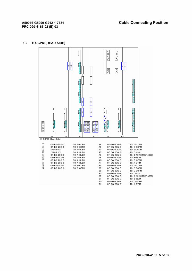
A50016-G5000-G212-1-7631 Cable Connecting PositionPRC-090-4165-02 (E)-03
PRC-090-4165 5 of 32
1.2 E-CCPM (REAR SIDE)
30 25 20 15 10 05E-CCPM (Rear Side)
① OF-BG-2CG-S TO: E-CCPM AA OF-BG-2CG-S TO: D-CCPM② OF-BG-2CG-S TO: E-CCPM AB OF-BG-2CG-S TO: E-CCPM③ 2P24LL-E1 TO: A-HUBM AC OF-BG-2CG-S TO: E-CCPM④ 2P24LL-E1 TO: A-HUBM AD OF-BG-2CG-S TO: C-LSM⑤ OF-BB-2CG-S TO: A-HUBM AE OF-BG-2CG-S TO: B-MHM (TRKF A000)⑥ OF-BB-2CG-S TO: A-HUBM AF OF-BG-2CG-S TO: B-SIGM⑦ OF-BB-2CG-S TO: A-HUBM AG OF-BG-2CG-S TO: C-GTPM⑧ OF-BB-2CG-S TO: A-HUBM AH OF-BG-2CG-S TO: A-DTIM⑨ OF-BG-2CG-S TO: E-CCPM BA OF-BG-2CG-S TO: D-CCPM⑩ OF-BG-2CG-S TO: E-CCPM BB OF-BG-2CG-S TO: E-CCPM
BC OF-BG-2CG-S TO: E-CCPMBD OF-BG-2CG-S TO: C-LSMBE OF-BG-2CG-S TO: B-MHM (TRKF A000)BF OF-BG-2CG-S TO: B-SIGMBG OF-BG-2CG-S TO: C-GTPMBH OF-BG-2CG-S TO: A-DTIM
BE
② ①
AA
AB
AC
AD
AE
AF
AG
AH
BA
BB
BC
BD
BF
BG
BH
⑥
⑤⑦
⑧
⑨⑩
③
④
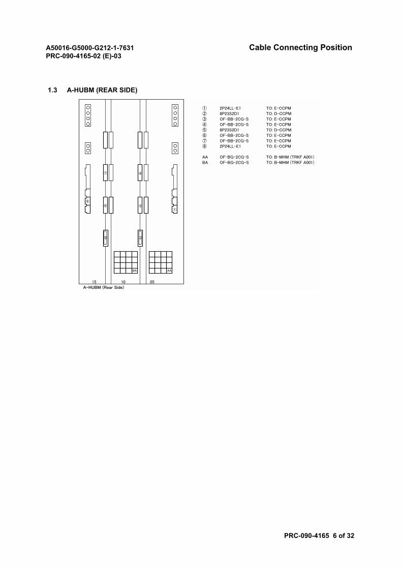
A50016-G5000-G212-1-7631 Cable Connecting PositionPRC-090-4165-02 (E)-03
PRC-090-4165 6 of 32
1.3 A-HUBM (REAR SIDE)
① 2P24LL-E1 TO: E-CCPM② 8P23S2D1 TO: D-CCPM③ OF-BB-2CG-S TO: E-CCPM④ OF-BB-2CG-S TO: E-CCPM⑤ 8P23S2D1 TO: D-CCPM⑥ OF-BB-2CG-S TO: E-CCPM⑦ OF-BB-2CG-S TO: E-CCPM⑧ 2P24LL-E1 TO: E-CCPM
AA OF-BG-2CG-S TO: B-MHM (TRKF A001)BA OF-BG-2CG-S TO: B-MHM (TRKF A001)
15 10 05A-HUBM (Rear Side)
AA
⑧
①
BA
②⑤
③
④⑦
⑥
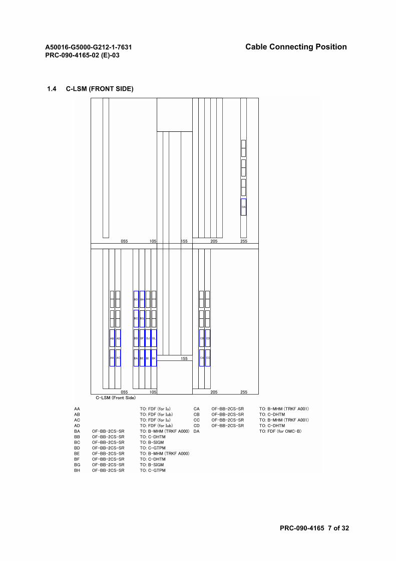
A50016-G5000-G212-1-7631 Cable Connecting PositionPRC-090-4165-02 (E)-03
PRC-090-4165 7 of 32
1.4 C-LSM (FRONT SIDE)
055 105 155 205 255
155
055 105 155 205 255C-LSM (Front Side)
AA TO: FDF (for Iu) CA OF-BB-2CS-SR TO: B-MHM (TRKF A001)AB TO: FDF (for Iub) CB OF-BB-2CS-SR TO: C-DHTMAC TO: FDF (for Iu) CC OF-BB-2CS-SR TO: B-MHM (TRKF A001)AD TO: FDF (for Iub) CD OF-BB-2CS-SR TO: C-DHTMBA OF-BB-2CS-SR TO: B-MHM (TRKF A000) DA TO: FDF (for OMC-B)BB OF-BB-2CS-SR TO: C-DHTMBC OF-BB-2CS-SR TO: B-SIGMBD OF-BB-2CS-SR TO: C-GTPMBE OF-BB-2CS-SR TO: B-MHM (TRKF A000)BF OF-BB-2CS-SR TO: C-DHTMBG OF-BB-2CS-SR TO: B-SIGMBH OF-BB-2CS-SR TO: C-GTPM
AB
AA AC
AD
BD BH
BC BG
BB BF BJ BL
BA BE BI BK
CB CD
CA CC
DA
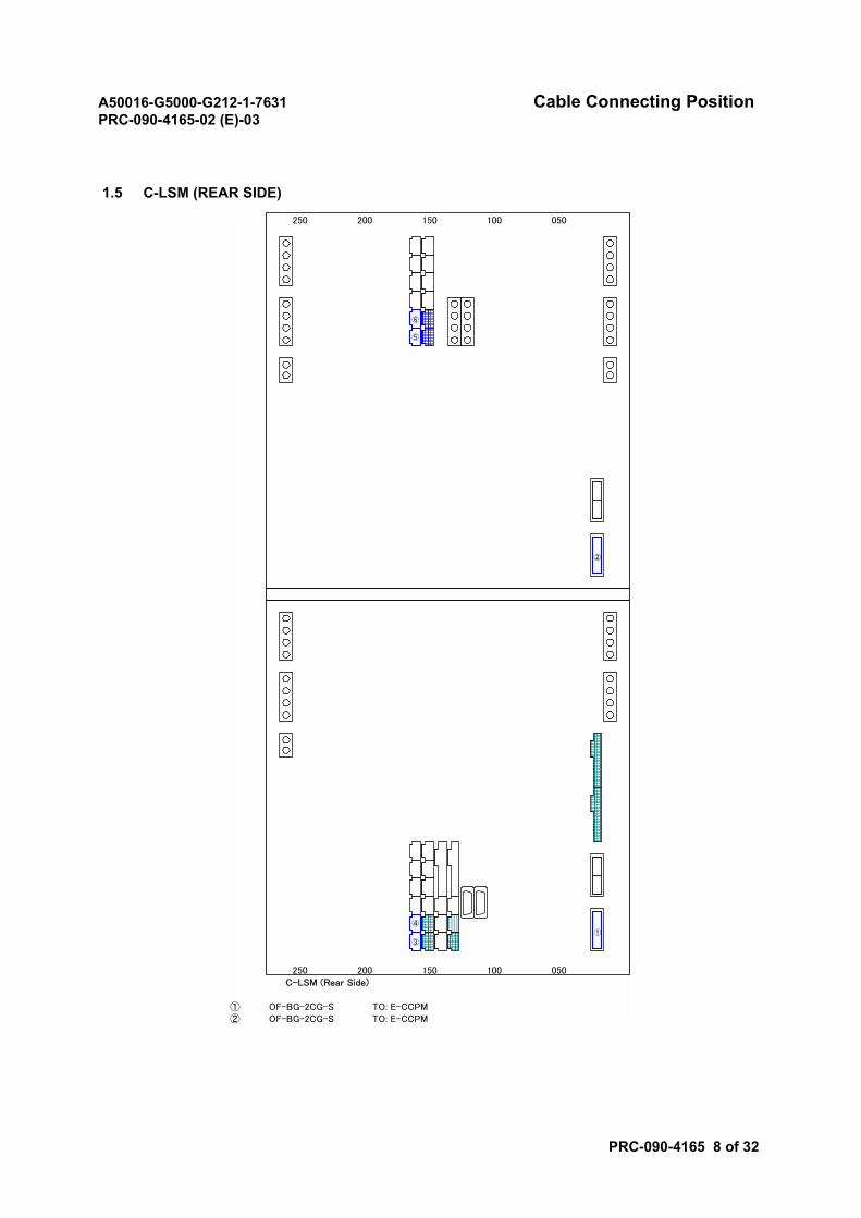
A50016-G5000-G212-1-7631 Cable Connecting PositionPRC-090-4165-02 (E)-03
PRC-090-4165 8 of 32
1.5 C-LSM (REAR SIDE)
250 200 150 100 050
250 200 150 100 050C-LSM (Rear Side)
① OF-BG-2CG-S TO: E-CCPM② OF-BG-2CG-S TO: E-CCPM
②
①
⑥
⑤
④
③
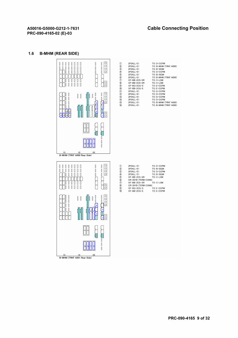
A50016-G5000-G212-1-7631 Cable Connecting PositionPRC-090-4165-02 (E)-03
PRC-090-4165 9 of 32
1.6 B-MHM (REAR SIDE)
① 2P24LL-E1 TO: D-CCPM② 2P24LL-E1 TO: B-MHM (TRKF A000)③ 2P24LL-E1 TO: B-SIGM④ 2P24LL-E1 TO: D-CCPM⑤ 2P24LL-E1 TO: B-SIGM⑥ 2P24LL-E1 TO: B-MHM (TRKF A000)⑦ OF-BB-2CS-SR TO: C-LSM⑧ OF-BB-2CS-SR TO: C-LSM⑨ OF-BG-2CG-S TO: E-CCPM⑩ OF-BB-2CG-S TO: E-CCPM⑪ 2P24LL-E1 TO: D-CCPM⑫ 2P24LL-E1 TO: D-CCPM⑬ 2P24LL-E1 TO: D-CCPM⑭ 2P24LL-E1 TO: D-CCPM⑮ 2P24LL-E1 TO: B-MHM (TRKF A000)⑯ 2P24LL-E1 TO: B-MHM (TRKF A000)
15 10 05B-MHM (TRKF A000 Rear Side)
⑨⑩ ⑦⑧
④
①
⑭
⑬
⑫
⑪
③
⑯
⑥
②⑤
⑮
① 2P24LL-E1 TO: D-CCPM② 2P24LL-E1 TO: B-SIGM③ 2P24LL-E1 TO: D-CCPM④ 2P24LL-E1 TO: B-SIGM⑤ OF-BB-2CS-SR TO: C-LSM⑥ CR-26YB (TERM CONN)⑦ OF-BB-2CS-SR TO: C-LSM⑧ CR-26YB (TERM CONN)⑨ OF-BG-2CG-S TO: E-CCPM⑩ OF-BB-2CG-S TO: E-CCPM
15 10 05B-MHM (TRKF A001 Rear Side)
⑨⑩ ⑤⑦
③
①
④
②⑧ ⑥
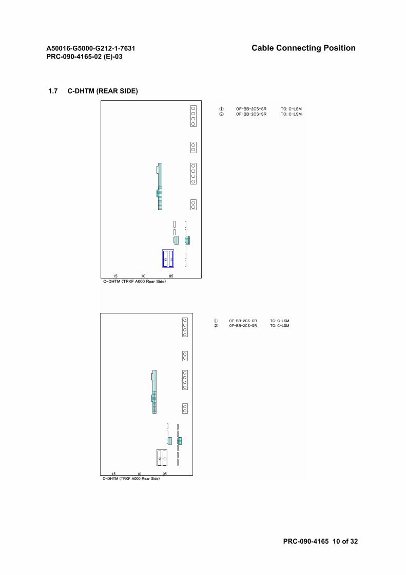
A50016-G5000-G212-1-7631 Cable Connecting PositionPRC-090-4165-02 (E)-03
PRC-090-4165 10 of 32
1.7 C-DHTM (REAR SIDE)
① OF-BB-2CS-SR TO: C-LSM② OF-BB-2CS-SR TO: C-LSM
15 10 05C-DHTM (TRKF A000 Rear Side)
①②
① OF-BB-2CS-SR TO: C-LSM
② OF-BB-2CS-SR TO: C-LSM
15 10 05C-DHTM (TRKF A000 Rear Side)
①②
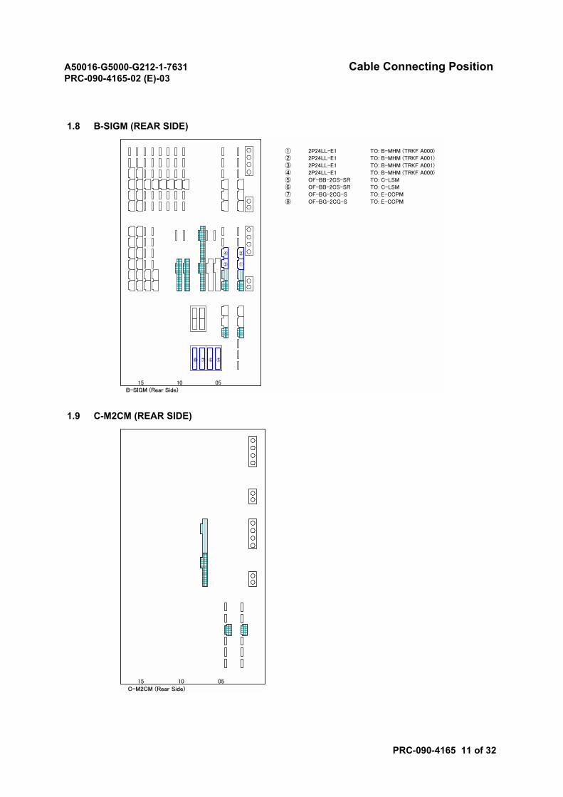
A50016-G5000-G212-1-7631 Cable Connecting PositionPRC-090-4165-02 (E)-03
PRC-090-4165 11 of 32
1.8 B-SIGM (REAR SIDE)
1.9 C-M2CM (REAR SIDE)
① 2P24LL-E1 TO: B-MHM (TRKF A000)② 2P24LL-E1 TO: B-MHM (TRKF A001)③ 2P24LL-E1 TO: B-MHM (TRKF A001)④ 2P24LL-E1 TO: B-MHM (TRKF A000)⑤ OF-BB-2CS-SR TO: C-LSM⑥ OF-BB-2CS-SR TO: C-LSM⑦ OF-BG-2CG-S TO: E-CCPM⑧ OF-BG-2CG-S TO: E-CCPM
15 10 05B-SIGM (Rear Side)
⑦⑧ ⑤⑥
②
①
④
③
15 10 05C-M2CM (Rear Side)
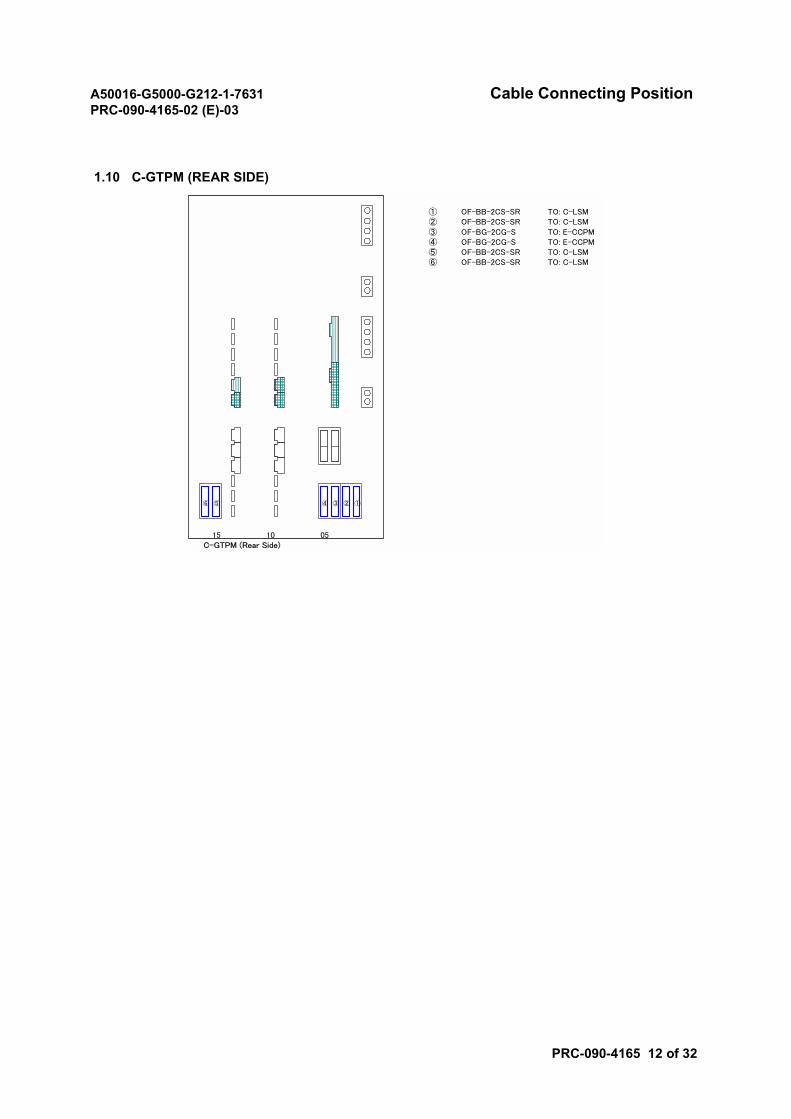
A50016-G5000-G212-1-7631 Cable Connecting PositionPRC-090-4165-02 (E)-03
PRC-090-4165 12 of 32
1.10 C-GTPM (REAR SIDE)
① OF-BB-2CS-SR TO: C-LSM② OF-BB-2CS-SR TO: C-LSM③ OF-BG-2CG-S TO: E-CCPM④ OF-BG-2CG-S TO: E-CCPM⑤ OF-BB-2CS-SR TO: C-LSM⑥ OF-BB-2CS-SR TO: C-LSM
15 10 05C-GTPM (Rear Side)
③④ ①②⑤⑥
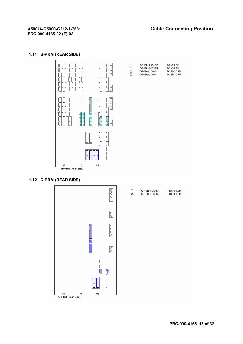
A50016-G5000-G212-1-7631 Cable Connecting PositionPRC-090-4165-02 (E)-03
PRC-090-4165 13 of 32
1.11 B-PRM (REAR SIDE)
1.12 C-PRM (REAR SIDE)
① OF-BB-2CS-SR TO: C-LSM② OF-BB-2CS-SR TO: C-LSM③ OF-BG-2CG-S TO: E-CCPM④ OF-BG-2CG-S TO: E-CCPM
15 10 05B-PRM (Rear Side)
③④ ①②
① OF-BB-2CS-SR TO: C-LSM
② OF-BB-2CS-SR TO: C-LSM
15 10 05
C-PRM (Rear Side)
①②
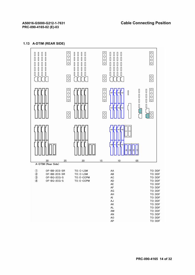
A50016-G5000-G212-1-7631 Cable Connecting PositionPRC-090-4165-02 (E)-03
PRC-090-4165 14 of 32
1.13 A-DTIM (REAR SIDE)
30 25 20 15 10 05A-DTIM (Rear Side)
① OF-BB-2CS-SR TO: C-LSM AA TO: DDF② OF-BB-2CS-SR TO: C-LSM AB TO: DDF
③ OF-BG-2CG-S TO: E-CCPM AC TO: DDF④ OF-BG-2CG-S TO: E-CCPM AD TO: DDF
AE TO: DDF
AF TO: DDFAG TO: DDF
AH TO: DDFAI TO: DDFAJ TO: DDF
AK TO: DDFAL TO: DDFAM TO: DDF
AN TO: DDFAO TO: DDFAP TO: DDF
③④ ①②
AA
ABAFAN
AM
AJ
AEAI
AC
ADAHAP
AO
AL
AGAK
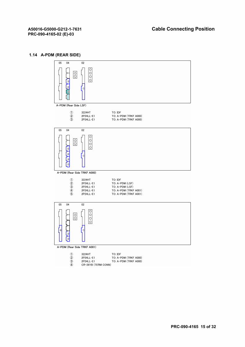
A50016-G5000-G212-1-7631 Cable Connecting PositionPRC-090-4165-02 (E)-03
PRC-090-4165 15 of 32
1.14 A-PDM (REAR SIDE)
05 04 02
A-PDM (Rear Side LSF)
① 3224HT TO: IDF② 2P24LL-E1 TO: A-PDM (TRKF A000)③ 2P24LL-E1 TO: A-PDM (TRKF A000)
05 04 02
A-PDM (Rear Side TRKF A000)
① 3224HT TO: IDF② 2P24LL-E1 TO: A-PDM (LSF)③ 2P24LL-E1 TO: A-PDM (LSF)④ 2P24LL-E1 TO: A-PDM (TRKF A001)⑤ 2P24LL-E1 TO: A-PDM (TRKF A001)
05 04 02
A-PDM (Rear Side TRKF A001)
① 3224HT TO: IDF② 2P24LL-E1 TO: A-PDM (TRKF A000)③ 2P24LL-E1 TO: A-PDM (TRKF A000)④ CR-26YB (TERM CONN)
②①
③
④①
⑤
③
②
①
③
②
④

A50016-G5000-G212-1-7631 Cable Connecting PositionPRC-090-4165-02 (E)-03
PRC-090-4165 16 of 32
2. Frame Type: B-LSF, A-PRF, C-TRKF, E-TRKF
• A-GTPM (REAR SIDE)
• A-PRM (REAR SIDE)
• B-LSM (FRONT SIDE)
• B-LSM (REAR SIDE)
• B-MHM (REAR SIDE)
• B-SIGM (REAR SIDE)
• C-CMPM (REAR SIDE)
Note: CMPM: Composite/Decomposite Module
• A-HUBM (REAR SIDE)
• B-DHTM (REAR SIDE)
• C-DHTM (REAR SIDE)
• C-M2CM (REAR SIDE)
• D-CMPM (REAR SIDE)
• D-CCPM (REAR SIDE)
• E-CCPM (REAR SIDE)
• A-FUSE (FOR LSF)
Note: FUSE: Fuse Panel
• A-FUSE (FOR C-TRKF)
• A-FUSE (FOR PRF)
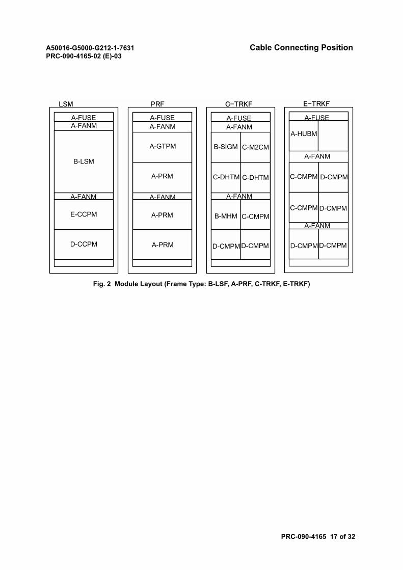
A50016-G5000-G212-1-7631 Cable Connecting PositionPRC-090-4165-02 (E)-03
PRC-090-4165 17 of 32
Fig. 2 Module Layout (Frame Type: B-LSF, A-PRF, C-TRKF, E-TRKF)
LSM PRF C-TRKF
A-FUSE
B-LSM
E-CCPM
A-FUSE
A-GTPM
A-PRM
D-CCPM
A-FANM
A-FANM
A-FANM
A-PRM
A-PRM
A-FANM
A-FUSEA-FANM
B-SIGM C-M2CM
C-DHTM C-DHTM
A-FANM
B-MHM C-CMPM
D-CMPM D-CMPM
E-TRKF
A-FUSE
A-HUBM
C-CMPM D-CMPM
A-FANM
C-CMPM D-CMPM
D-CMPM D-CMPM
A-FANM
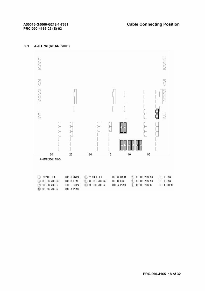
A50016-G5000-G212-1-7631 Cable Connecting PositionPRC-090-4165-02 (E)-03
PRC-090-4165 18 of 32
2.1 A-GTPM (REAR SIDE)
2025 15 10 0530
A-GTPM(REAR SIDE)
2P24LL-E1
1
2
1 TO: C-CMPM 2P24LL-E12 TO: C-CMPM OF-BB-2CS-SR3 TO: B-LSM
345679
810
OF-BB-2CS-SR4 TO: B-LSM OF-BB-2CS-SR5 TO: B-LSM OF-BB-2CS-SR6 TO: B-LSM
OF-BG-2CG-S7 TO: E-CCPM OF-BG-2CG-S8 TO: A-PRM0 OF-BG-2CG-S9 TO: E-CCPM
OF-BG-2CG-S10 TO: A-PRM0
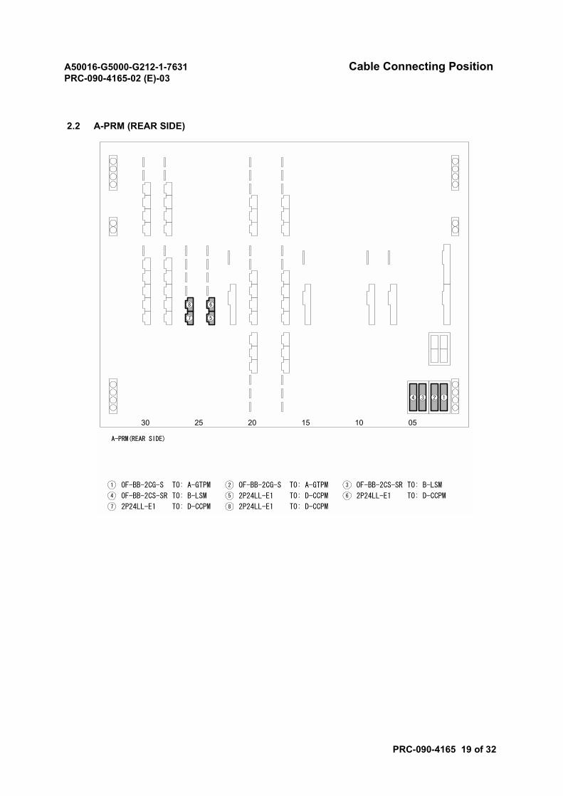
A50016-G5000-G212-1-7631 Cable Connecting PositionPRC-090-4165-02 (E)-03
PRC-090-4165 19 of 32
2.2 A-PRM (REAR SIDE)
2025 15 10 0530
A-PRM(REAR SIDE)
OF-BB-2CG-S1 TO: A-GTPM
1234
6
5
8
7
OF-BB-2CG-S2 TO: A-GTPM OF-BB-2CS-SR3 TO: B-LSM
OF-BB-2CS-SR4 TO: B-LSM 2P24LL-E15 TO: D-CCPM 2P24LL-E16 TO: D-CCPM
2P24LL-E17 TO: D-CCPM 2P24LL-E18 TO: D-CCPM
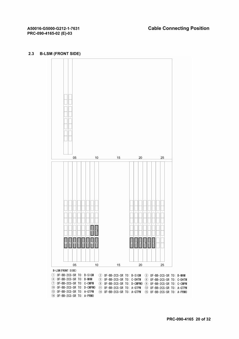
A50016-G5000-G212-1-7631 Cable Connecting PositionPRC-090-4165-02 (E)-03
PRC-090-4165 20 of 32
2.3 B-LSM (FRONT SIDE)
OF-BB-2CS-SR1 TO: B-SIGM OF-BB-2CS-SR2 TO: B-SIGMOF-BB-2CS-SR4 TO: B-MHM OF-BB-2CS-SR5 TO: C-DHTM
OF-BB-2CS-SR13 TO: A-GTPM
OF-BB-2CS-SR7 TO: C-CMPM
OF-BB-2CS-SR11 TO: A-GTPM
OF-BB-2CS-SR14 TO: A-GTPM
OF-BB-2CS-SR3 TO: B-MHM
OF-BB-2CS-SR6 TO: C-DHTMOF-BB-2CS-SR8 TO: D-CMPM0 OF-BB-2CS-SR9 TO: C-CMPM
OF-BB-2CS-SR10 TO: D-CMPM0 OF-BB-2CS-SR12 TO: A-GTPM
OF-BB-2CS-SR15 TO: A-PRM0OF-BB-2CS-SR16 TO: A-PRM0
20 25151005
B-LSM(FRONT SIDE)
1 2 3 4 5 6 7
8
9
10
11 12 13 14 15 16
20 25151005
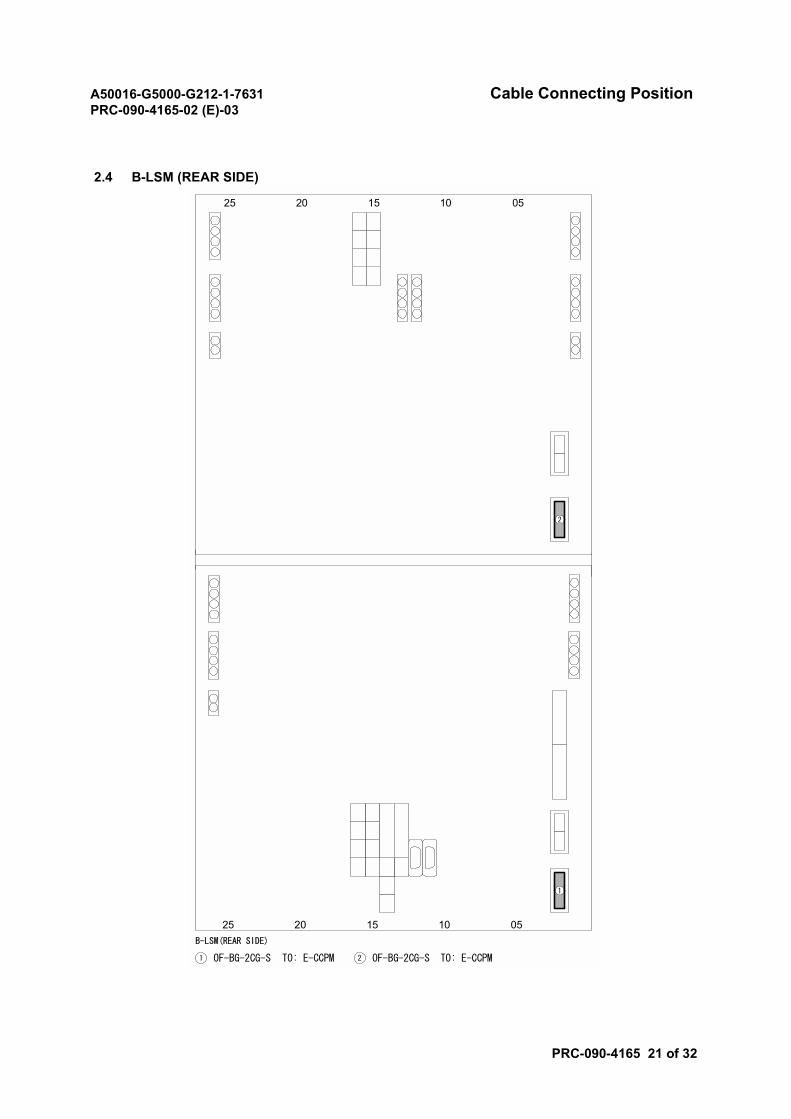
A50016-G5000-G212-1-7631 Cable Connecting PositionPRC-090-4165-02 (E)-03
PRC-090-4165 21 of 32
2.4 B-LSM (REAR SIDE)
2025 15 10 05B-LSM(REAR SIDE)
1
OF-BG-2CG-S1 TO: E-CCPM OF-BG-2CG-S2 TO: E-CCPM
2025 15 10 05
2
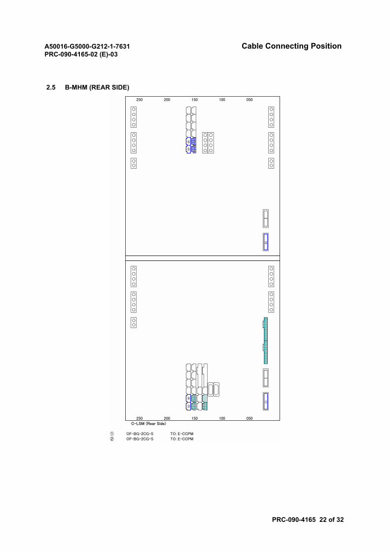
A50016-G5000-G212-1-7631 Cable Connecting PositionPRC-090-4165-02 (E)-03
PRC-090-4165 22 of 32
2.5 B-MHM (REAR SIDE)
250 200 150 100 050
250 200 150 100 050
C-LSM (Rear Side)
① OF-BG-2CG-S TO: E-CCPM② OF-BG-2CG-S TO: E-CCPM
②
①
⑥
⑤
④
③
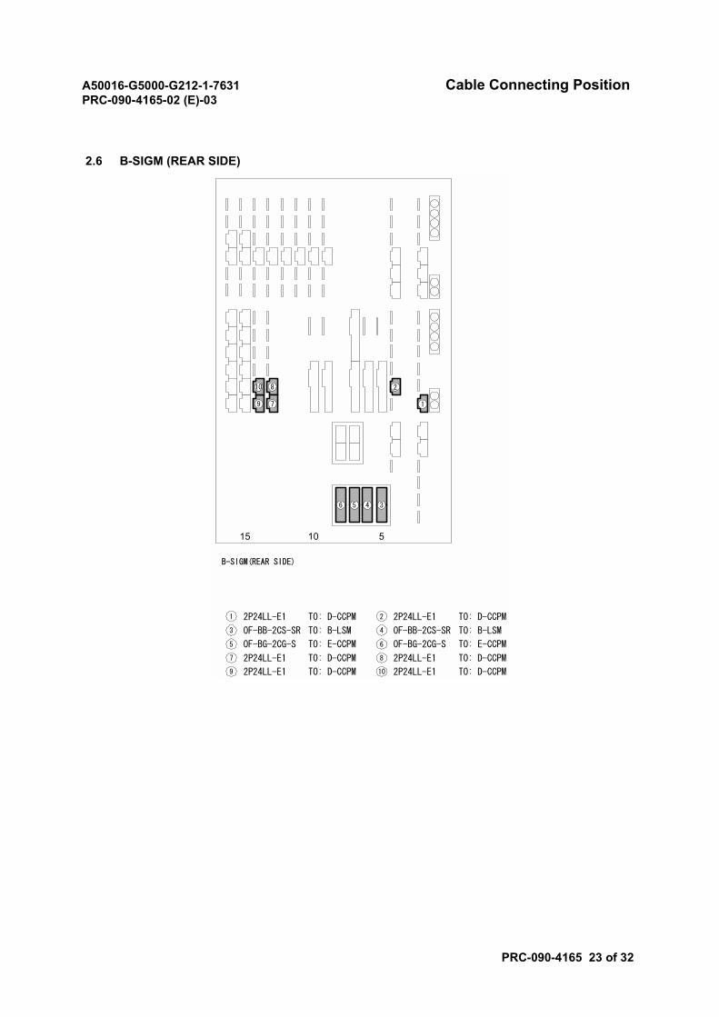
A50016-G5000-G212-1-7631 Cable Connecting PositionPRC-090-4165-02 (E)-03
PRC-090-4165 23 of 32
2.6 B-SIGM (REAR SIDE)
15 10 5
B-SIGM(REAR SIDE)
2P24LL-E11 TO: D-CCPM 2P24LL-E12 TO: D-CCPM
2P24LL-E17 TO: D-CCPM
OF-BB-2CS-SR3 TO: B-LSM OF-BB-2CS-SR4 TO: B-LSM
2P24LL-E19 TO: D-CCPM
OF-BG-2CG-S5 TO: E-CCPM OF-BG-2CG-S6 TO: E-CCPM
1
2
3456
7
8
9
10
2P24LL-E18 TO: D-CCPM
2P24LL-E110 TO: D-CCPM
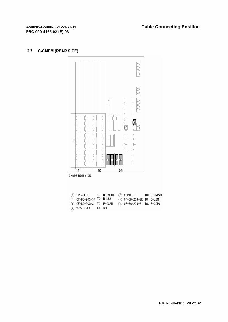
A50016-G5000-G212-1-7631 Cable Connecting PositionPRC-090-4165-02 (E)-03
PRC-090-4165 24 of 32
2.7 C-CMPM (REAR SIDE)
15 0510
1
C-CMPM(REAR SIDE)
2
3456
2P24LL-E11 TO: D-CMPM1 2P24LL-E12 TO: D-CMPM0
OF-BB-2CS-SR3 TO: B-LSM OF-BB-2CS-SR4 TO: B-LSM
OF-BG-2CG-S5 TO: E-CCPM OF-BG-2CG-S6 TO: E-CCPM
7
2P24CT-E17 TO: DDF
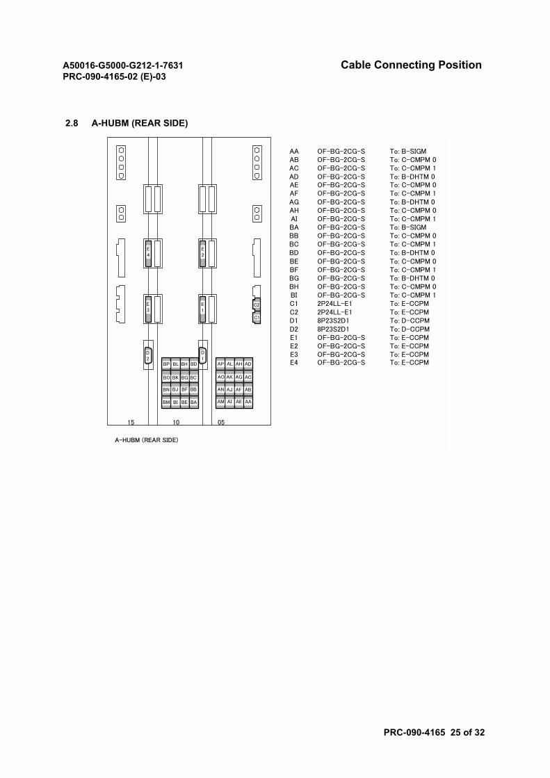
A50016-G5000-G212-1-7631 Cable Connecting PositionPRC-090-4165-02 (E)-03
PRC-090-4165 25 of 32
2.8 A-HUBM (REAR SIDE)
AA OF-BG-2CG-S To: B-SIGMAB OF-BG-2CG-S To: C-CMPM 0AC OF-BG-2CG-S To: C-CMPM 1AD OF-BG-2CG-S To: B-DHTM 0AE OF-BG-2CG-S To: C-CMPM 0AF OF-BG-2CG-S To: C-CMPM 1AG OF-BG-2CG-S To: B-DHTM 0AH OF-BG-2CG-S To: C-CMPM 0AI OF-BG-2CG-S To: C-CMPM 1BA OF-BG-2CG-S To: B-SIGMBB OF-BG-2CG-S To: C-CMPM 0BC OF-BG-2CG-S To: C-CMPM 1BD OF-BG-2CG-S To: B-DHTM 0BE OF-BG-2CG-S To: C-CMPM 0BF OF-BG-2CG-S To: C-CMPM 1BG OF-BG-2CG-S To: B-DHTM 0BH OF-BG-2CG-S To: C-CMPM 0BI OF-BG-2CG-S To: C-CMPM 1C1 2P24LL-E1 To: E-CCPMC2 2P24LL-E1 To: E-CCPMD1 8P23S2D1 To: D-CCPMD2 8P23S2D1 To: D-CCPME1 OF-BG-2CG-S To: E-CCPME2 OF-BG-2CG-S To: E-CCPME3 OF-BG-2CG-S To: E-CCPME4 OF-BG-2CG-S To: E-CCPM
15 10 05
AA
AB
AC
AD
AE
AF
AG
AH
AI
AJ
AK
AL
AM
AN
AO
AP
BA
BB
BC
BD
BE
BF
BG
BH
BI
BJ
BK
BL
BM
BN
BO
BP
C2
C1
E1
E2
D1
D2
E4
E3
A-HUBM (REAR SIDE)
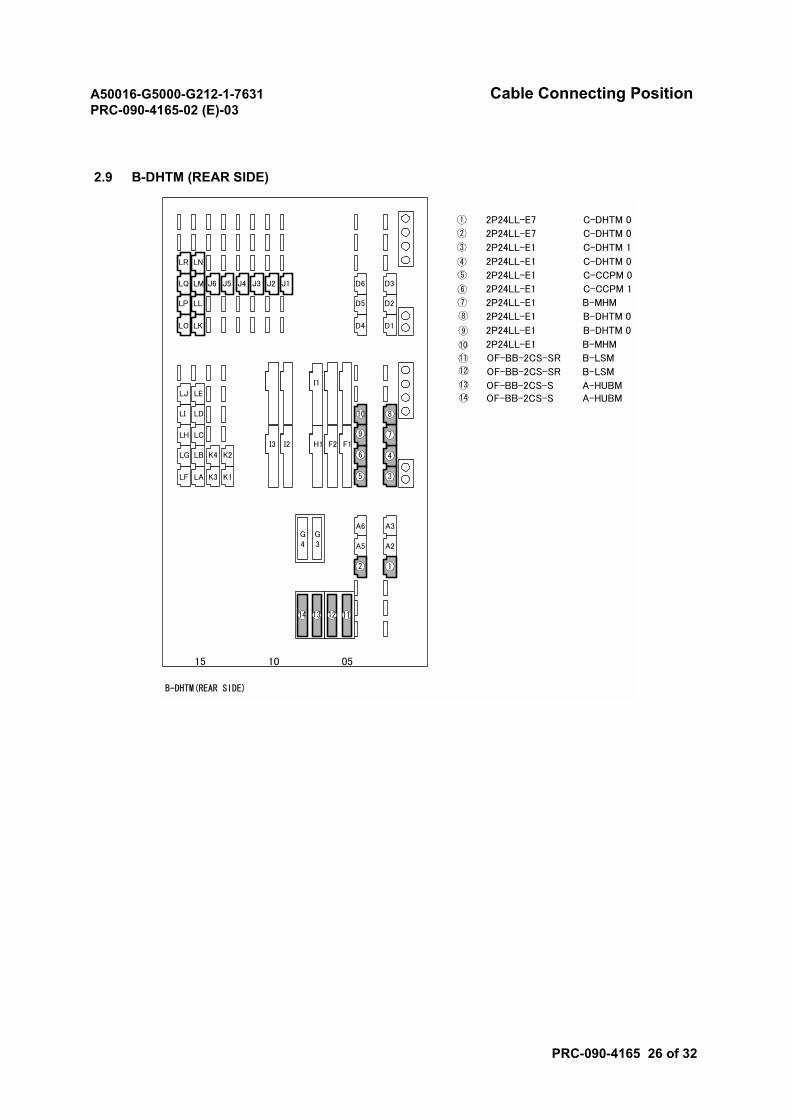
A50016-G5000-G212-1-7631 Cable Connecting PositionPRC-090-4165-02 (E)-03
PRC-090-4165 26 of 32
2.9 B-DHTM (REAR SIDE)
2P24LL-E7 C-DHTM 0
2P24LL-E7 C-DHTM 0
2P24LL-E1 C-DHTM 1
2P24LL-E1 C-DHTM 0
2P24LL-E1 C-CCPM 0
2P24LL-E1 C-CCPM 1
2P24LL-E1 B-MHM
2P24LL-E1 B-DHTM 0
2P24LL-E1 B-DHTM 0
2P24LL-E1 B-MHM
OF-BB-2CS-SR B-LSM
OF-BB-2CS-SR B-LSM
OF-BB-2CS-S A-HUBMOF-BB-2CS-S A-HUBM
15 10 05
G3
G4 A5 A2
D5
D4 D1
D2
D6 D3
LP
LO
LQ
LL
LK
LM
LG
LF
LH
LB
LA
LC
LI
LJ
LD
LE
K4
K3
K2
K1
J6 J5 J4 J3 J2 J1
F1F2I2I3 H1
I1
A6 A3
LR LN
1
1
2
2
3
3
4
4
5
5
6
6
7
7
8
8
9
9
10
10
11
1112
12
13
14
1314
B-DHTM(REAR SIDE)
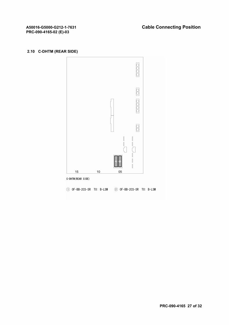
A50016-G5000-G212-1-7631 Cable Connecting PositionPRC-090-4165-02 (E)-03
PRC-090-4165 27 of 32
2.10 C-DHTM (REAR SIDE)
1015 05
C-DHTM(REAR SIDE)
OF-BB-2CS-SR1 TO: B-LSM OF-BB-2CS-SR2 TO: B-LSM
12
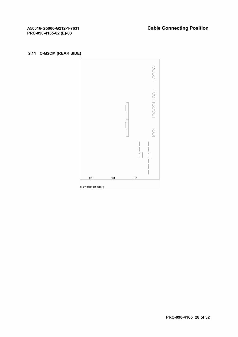
A50016-G5000-G212-1-7631 Cable Connecting PositionPRC-090-4165-02 (E)-03
PRC-090-4165 28 of 32
2.11 C-M2CM (REAR SIDE)
1015 05
C-M2CM(REAR SIDE)
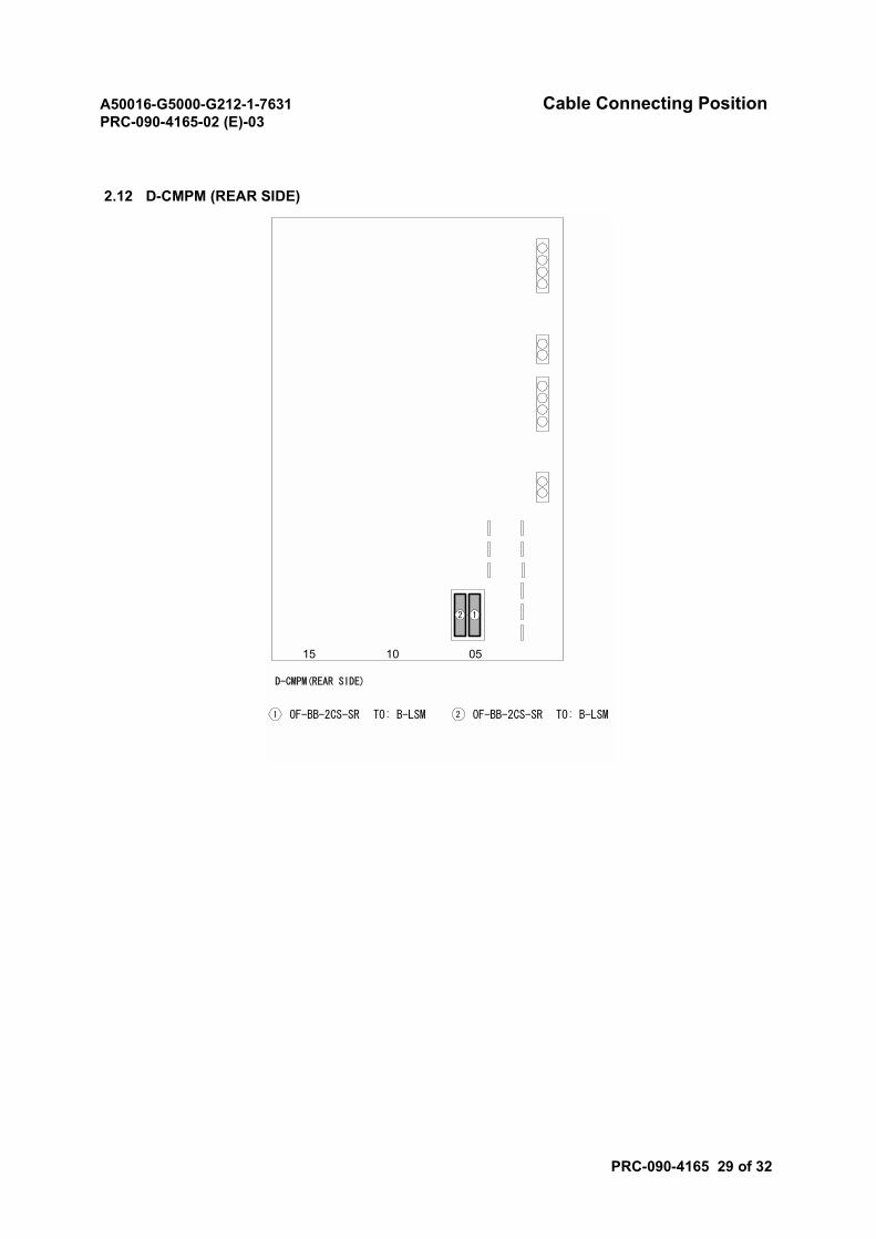
A50016-G5000-G212-1-7631 Cable Connecting PositionPRC-090-4165-02 (E)-03
PRC-090-4165 29 of 32
2.12 D-CMPM (REAR SIDE)
1015 05
D-CMPM(REAR SIDE)
OF-BB-2CS-SR1 TO: B-LSM OF-BB-2CS-SR2 TO: B-LSM
12
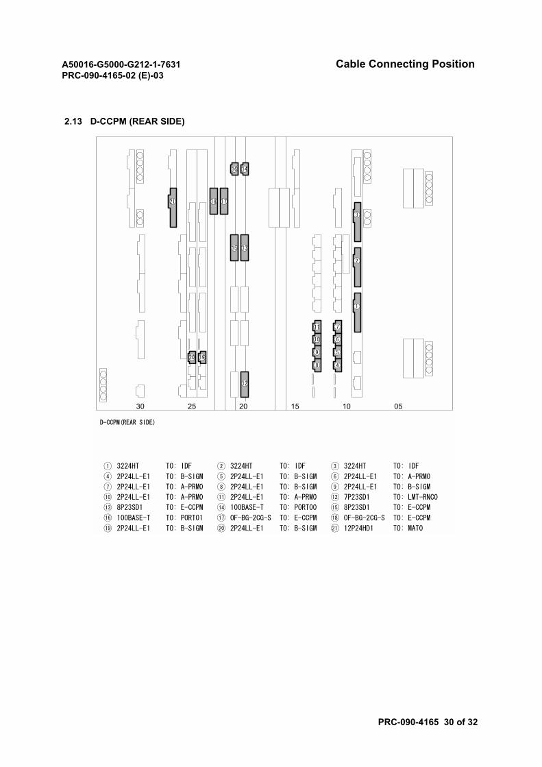
A50016-G5000-G212-1-7631 Cable Connecting PositionPRC-090-4165-02 (E)-03
PRC-090-4165 30 of 32
2.13 D-CCPM (REAR SIDE)
2025 15 10 0530
1
D-CCPM(REAR SIDE)
3224HT1 TO: IDF 3224HT2 TO: IDF
2P24LL-E14 TO: B-SIGM 2P24LL-E15 TO: B-SIGM
8P23SD113 TO: E-CCPM
2P24LL-E17 TO: A-PRM0
2P24LL-E111 TO: A-PRM0
100BASE-T14 TO: PORT00
2
3
4
5
6
7
8
9
10
11
12
1315
1718
1920
21
3224HT3 TO: IDF
2P24LL-E16 TO: A-PRM0
2P24LL-E18 TO: B-SIGM 2P24LL-E19 TO: B-SIGM
2P24LL-E110 TO: A-PRM0
1416
7P23SD112 TO: LMT-RNC0
8P23SD115 TO: E-CCPM
OF-BG-2CG-S17 TO: E-CCPM100BASE-T16 TO: PORT01 OF-BG-2CG-S18 TO: E-CCPM
2P24LL-E120 TO: B-SIGM2P24LL-E119 TO: B-SIGM 12P24HD121 TO: MAT0
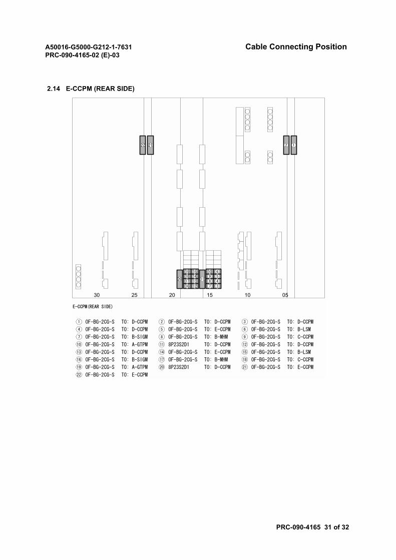
A50016-G5000-G212-1-7631 Cable Connecting PositionPRC-090-4165-02 (E)-03
PRC-090-4165 31 of 32
2.14 E-CCPM (REAR SIDE)
2025 15 10 0530
E-CCPM(REAR SIDE)
OF-BG-2CG-S1 TO: D-CCPM OF-BG-2CG-S2 TO: D-CCPM
OF-BG-2CG-S4 TO: D-CCPM OF-BG-2CG-S5 TO: E-CCPM
OF-BG-2CG-S13 TO: D-CCPM
OF-BG-2CG-S7 TO: B-SIGM
8P23S2D111 TO: D-CCPM
OF-BG-2CG-S14 TO: E-CCPM
OF-BG-2CG-S3 TO: D-CCPM
OF-BG-2CG-S6 TO: B-LSM
OF-BG-2CG-S8 TO: B-MHM OF-BG-2CG-S9 TO: C-CCPM
OF-BG-2CG-S10 TO: A-GTPM OF-BG-2CG-S12 TO: D-CCPM
OF-BG-2CG-S15 TO: B-LSM
OF-BG-2CG-S17 TO: B-MHMOF-BG-2CG-S16 TO: B-SIGM OF-BG-2CG-S18 TO: C-CCPM
8P23S2D120 TO: D-CCPMOF-BG-2CG-S19 TO: A-GTPM OF-BG-2CG-S21 TO: E-CCPM
12
345610
98712
13141519
181716
1120
2122
OF-BG-2CG-S22 TO: E-CCPM
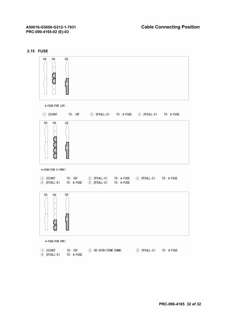
A50016-G5000-G212-1-7631 Cable Connecting PositionPRC-090-4165-02 (E)-03
PRC-090-4165 32 of 32
2.15 FUSE
A-FUSE(FOR LSF)
020405
3224HT1 TO: IDF 2P24LL-E12 TO: A-FUSE 2P24LL-E13 TO: A-FUSE
12
3
A-FUSE(FOR PRF)
02
1
A-FUSE(FOR C-TRKF)
3224HT1 TO: IDF 2P24LL-E12 TO: A-FUSE 2P24LL-E13 TO: A-FUSE
2P24LL-E14 TO: A-FUSE 2P24LL-E15 TO: A-FUSE
3224HT1 TO: IDF CR-26YB(TERM CONN)2 2P24LL-E13 TO: A-FUSE
2P24LL-E14 TO: A-FUSE
0204
1
3
4
04
4
5
2
3
05
05
A50016-G5000-G212-1-7631 Cabling TestPRC-090-4170-02 (E)-01
PRC-090-4170 1 of 2
Cabling Test
1. PROCEDURE
STEP ACTION/REMARKS
1 Prepare the cable continuity checker.1-1 Prepare the telephones for communication between the Distribution Frame (DF)
and the switching room.1-2 Place the cable continuity checker between the DF and the switching room (see
Fig. 1).
2 Check and identify each cable (see Fig. 1).2-1 Perform this test for the cables laid between the switch(es) and the DF.2-2 Check only the core No. 1 for each cable using the cable continuity checker.
CAUTION• Never swing a cable. Never wind a cable forcibly. Swinging a cable or
forcibly winding a cable can break the cable or damage its connector.• Never wind an optical cable to or from a loop with a diameter of 100
mm or less. To do so could cause the optical fiber to break.• Never remove the cap from an optical connector, except when
attaching the connector. If an optical connector is damaged orcontaminated with dust, a communication error can occur.
• When installing a cable rack or running cables above using a ladder,etc., watch your footing. A fall could result in personnel injuries orcause problems to the system.
• When installing a cable rack or running cables above, be careful notto drop any tool or component. Dropping a tool or a component caninjure personnel, or cause problems to the system.
• Use tools and components such as batteries and cables correctly inaccordance with the instructions given in the relevant manuals.
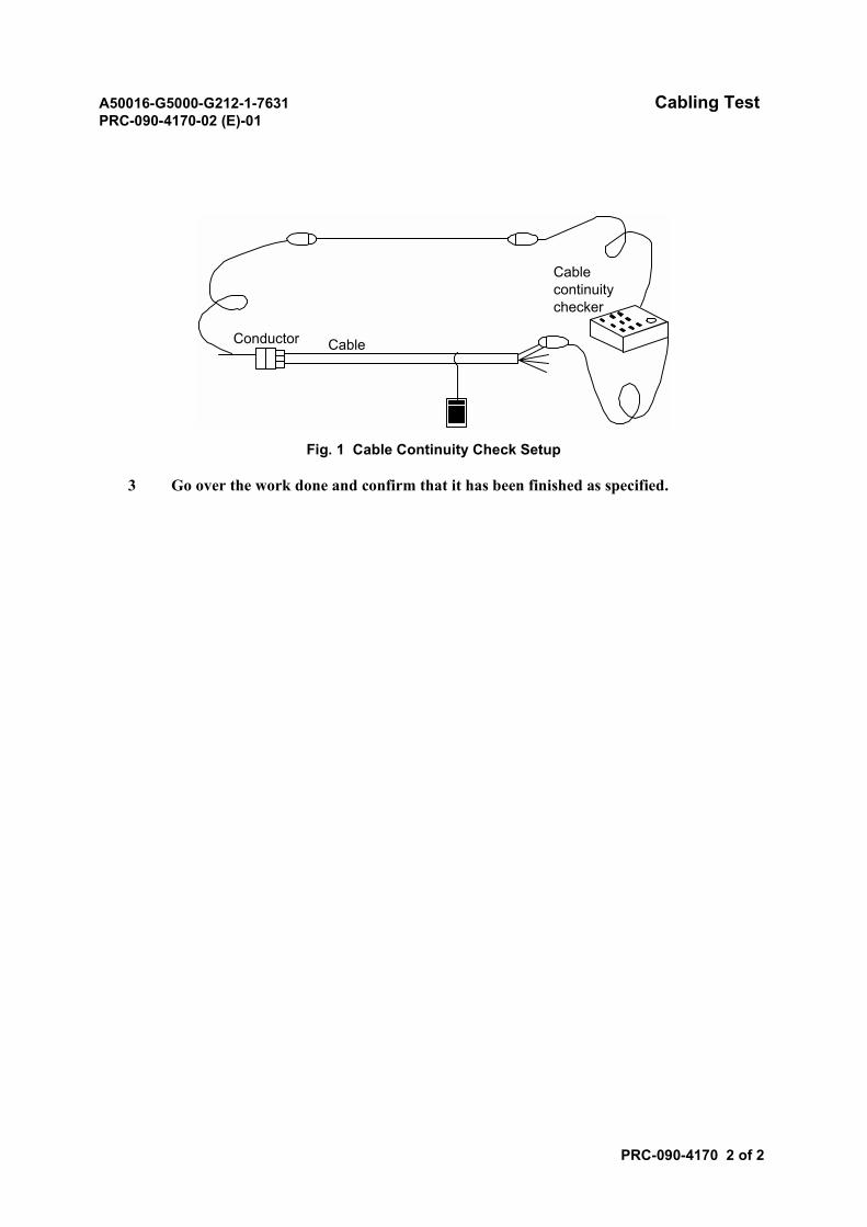
A50016-G5000-G212-1-7631 Cabling TestPRC-090-4170-02 (E)-01
PRC-090-4170 2 of 2
Fig. 1 Cable Continuity Check Setup
3 Go over the work done and confirm that it has been finished as specified.
CableConductor
Cablecontinuitychecker
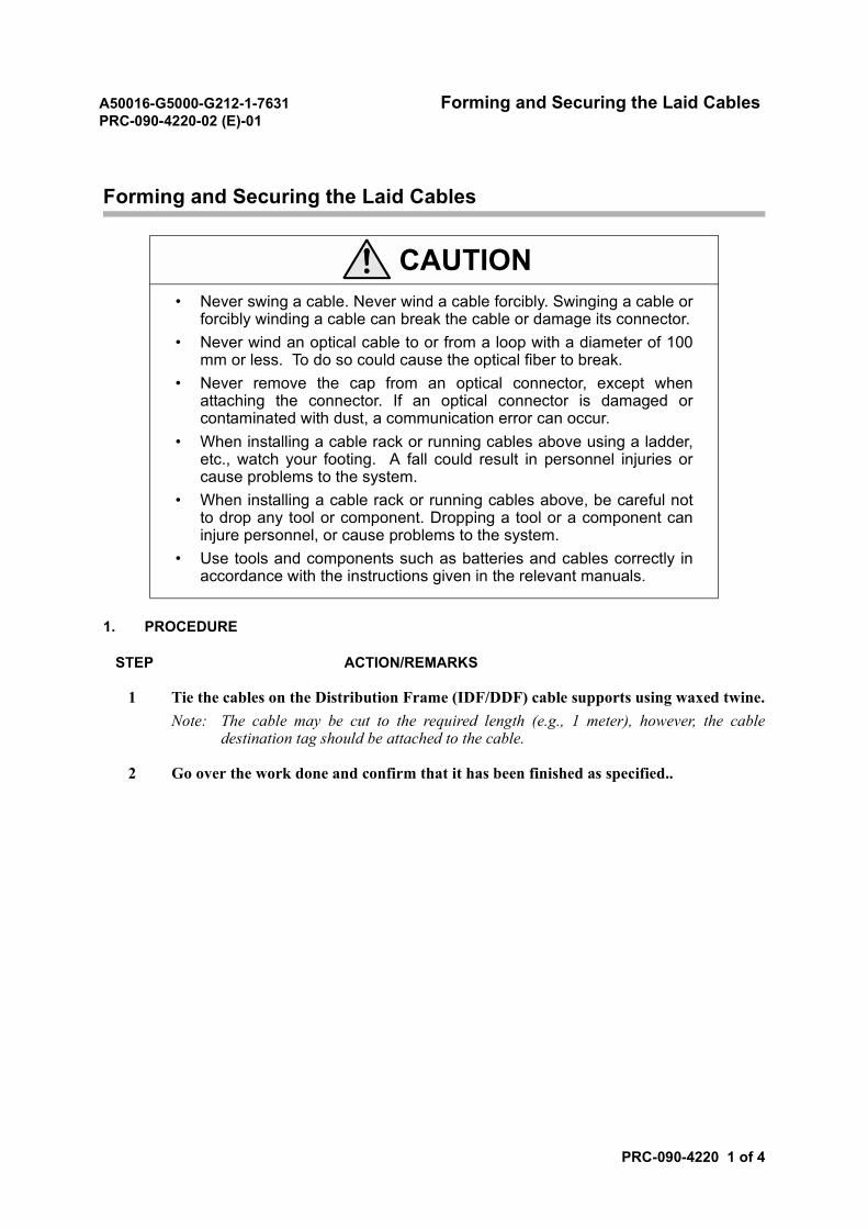
A50016-G5000-G212-1-7631 Forming and Securing the Laid CablesPRC-090-4220-02 (E)-01
PRC-090-4220 1 of 4
Forming and Securing the Laid Cables
1. PROCEDURE
STEP ACTION/REMARKS
1 Tie the cables on the Distribution Frame (IDF/DDF) cable supports using waxed twine.Note: The cable may be cut to the required length (e.g., 1 meter), however, the cable
destination tag should be attached to the cable.
2 Go over the work done and confirm that it has been finished as specified..
CAUTION• Never swing a cable. Never wind a cable forcibly. Swinging a cable or
forcibly winding a cable can break the cable or damage its connector.• Never wind an optical cable to or from a loop with a diameter of 100
mm or less. To do so could cause the optical fiber to break.• Never remove the cap from an optical connector, except when
attaching the connector. If an optical connector is damaged orcontaminated with dust, a communication error can occur.
• When installing a cable rack or running cables above using a ladder,etc., watch your footing. A fall could result in personnel injuries orcause problems to the system.
• When installing a cable rack or running cables above, be careful notto drop any tool or component. Dropping a tool or a component caninjure personnel, or cause problems to the system.
• Use tools and components such as batteries and cables correctly inaccordance with the instructions given in the relevant manuals.
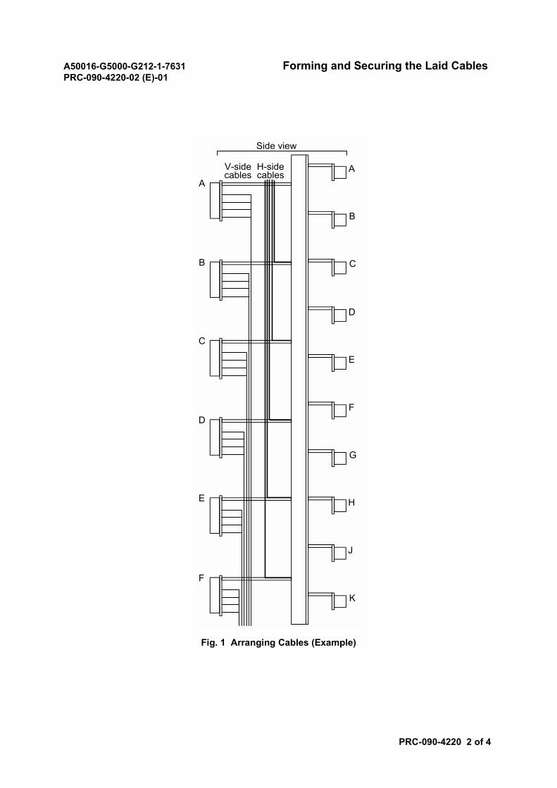
A50016-G5000-G212-1-7631 Forming and Securing the Laid CablesPRC-090-4220-02 (E)-01
PRC-090-4220 2 of 4
Fig. 1 Arranging Cables (Example)
A
B
C
D
E
F
Side view
V-sidecables
H-sidecables
A
B
C
D
E
F
G
H
J
K
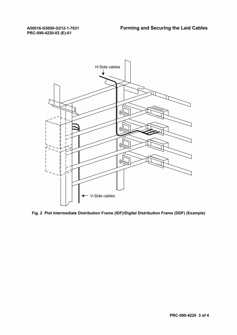
A50016-G5000-G212-1-7631 Forming and Securing the Laid CablesPRC-090-4220-02 (E)-01
PRC-090-4220 3 of 4
Fig. 2 Plot Intermediate Distribution Frame (IDF)/Digital Distribution Frame (DDF) (Example)
H-Side cables
V-Side cables
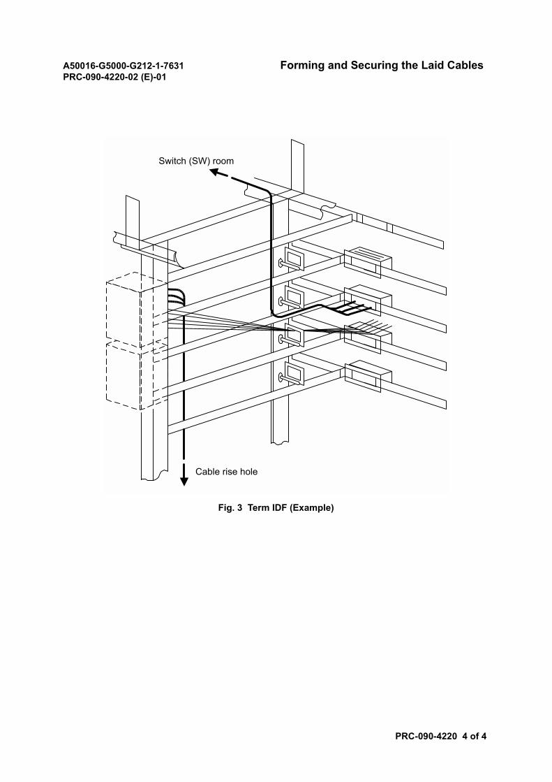
A50016-G5000-G212-1-7631 Forming and Securing the Laid CablesPRC-090-4220-02 (E)-01
PRC-090-4220 4 of 4
Fig. 3 Term IDF (Example)
Switch (SW) room
Cable rise hole
A50016-G5000-G212-1-7631 Cable Continuity TestPRC-090-4230-02 (E)-01
PRC-090-4230 1 of 2
Cable Continuity Test
1. REFERENCE INSTALLATION DRAWINGS
In this module, refer to the following installation drawing.
• Cable Running List
• IDF Wiring Chart
• IDF Jumper List
Note: Refer to the actual Installation Drawing.
2. PROCEDURE
STEP ACTION/REMARKS
1 Prepare the cable continuity checker.1-1 Prepare the telephones for communication between the Distribution Frame (DF)
and switching rooms.1-2 Set the cable continuity checker between the DF and switching rooms (see Fig. 1).
CAUTION• Before making a cable connection, be sure to turn OFF the switch on
the power distribution board. Failure to do so could result in anelectrical shock or other accident.
• When making a connection with a cable conductor, be careful not tolet the conductor touch another cable conductor. A short-circuit cancause a fire.
• When installing a power cable, check that the connection is secure. Ifa power cable is not screwed tightly, the cable can overheat, resultingin a fire.
• Use test equipment with the correct voltage (230 V). Using the wrongvoltage can cause a fire.
• Normal operation of the system is not guaranteed when the inputvoltage is out of the prescribed range. The system operation is notguaranteed even when the voltage returns to the normal level after itbecomes out of the range. In this case, it is necessary to reset thesystem.
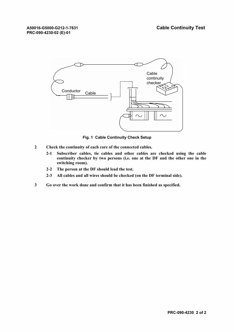
A50016-G5000-G212-1-7631 Cable Continuity TestPRC-090-4230-02 (E)-01
PRC-090-4230 2 of 2
Fig. 1 Cable Continuity Check Setup
2 Check the continuity of each core of the connected cables.2-1 Subscriber cables, tie cables and other cables are checked using the cable
continuity checker by two persons (i.e. one at the DF and the other one in theswitching room).
2-2 The person at the DF should lead the test.2-3 All cables and all wires should be checked (on the DF terminal side).
3 Go over the work done and confirm that it has been finished as specified.
Conductor Cable
Cablecontinuitychecker
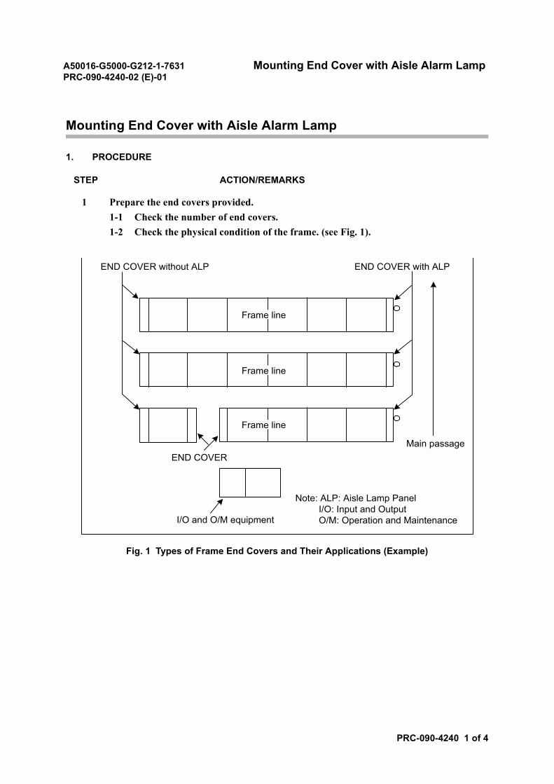
A50016-G5000-G212-1-7631 Mounting End Cover with Aisle Alarm LampPRC-090-4240-02 (E)-01
PRC-090-4240 1 of 4
Mounting End Cover with Aisle Alarm Lamp
1. PROCEDURE
STEP ACTION/REMARKS
1 Prepare the end covers provided.1-1 Check the number of end covers.1-2 Check the physical condition of the frame. (see Fig. 1).
Fig. 1 Types of Frame End Covers and Their Applications (Example)
Frame line
Frame line
Frame line
END COVER without ALP END COVER with ALP
END COVERMain passage
I/O and O/M equipment
Note: ALP: Aisle Lamp Panel I/O: Input and Output O/M: Operation and Maintenance
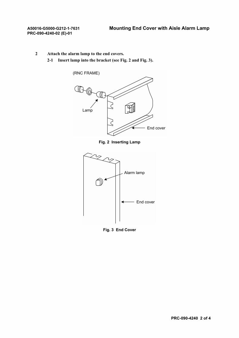
A50016-G5000-G212-1-7631 Mounting End Cover with Aisle Alarm LampPRC-090-4240-02 (E)-01
PRC-090-4240 2 of 4
2 Attach the alarm lamp to the end covers.2-1 Insert lamp into the bracket (see Fig. 2 and Fig. 3).
Fig. 2 Inserting Lamp
Fig. 3 End Cover
End cover
Lamp
(RNC FRAME)
Alarm lamp
End cover
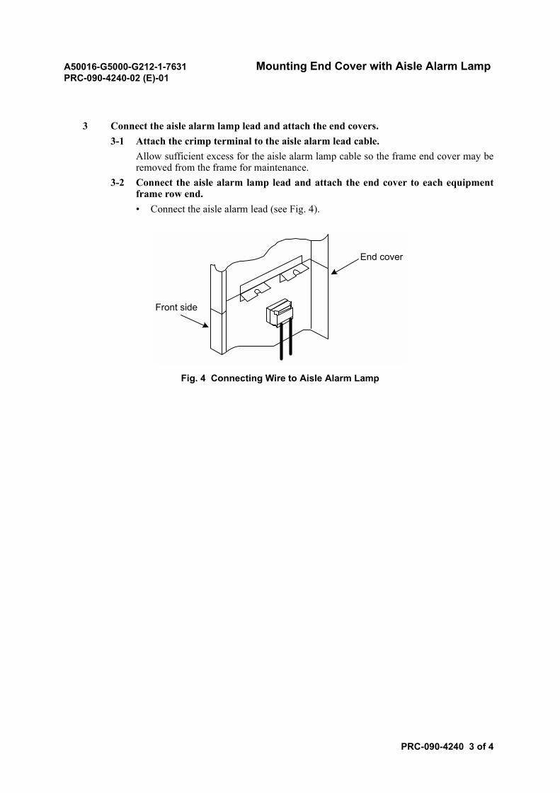
A50016-G5000-G212-1-7631 Mounting End Cover with Aisle Alarm LampPRC-090-4240-02 (E)-01
PRC-090-4240 3 of 4
3 Connect the aisle alarm lamp lead and attach the end covers.3-1 Attach the crimp terminal to the aisle alarm lead cable.
Allow sufficient excess for the aisle alarm lamp cable so the frame end cover may beremoved from the frame for maintenance.
3-2 Connect the aisle alarm lamp lead and attach the end cover to each equipmentframe row end.• Connect the aisle alarm lead (see Fig. 4).
Fig. 4 Connecting Wire to Aisle Alarm Lamp
End cover
Front side
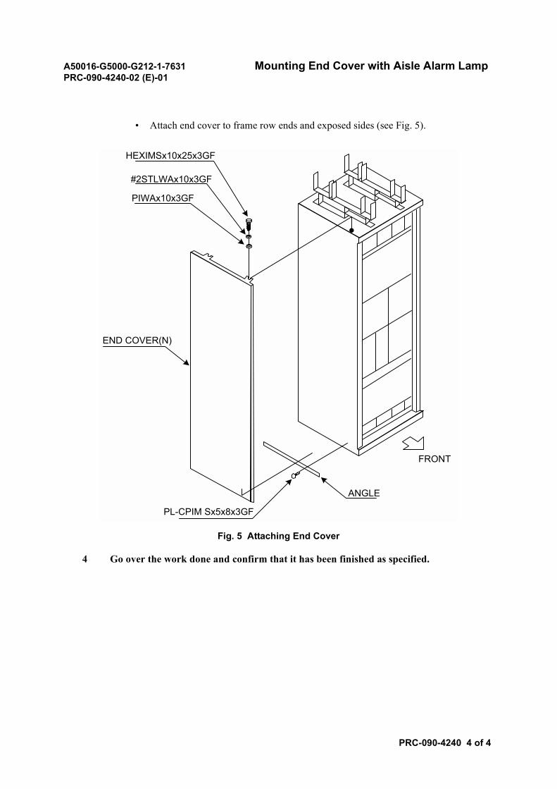
A50016-G5000-G212-1-7631 Mounting End Cover with Aisle Alarm LampPRC-090-4240-02 (E)-01
PRC-090-4240 4 of 4
• Attach end cover to frame row ends and exposed sides (see Fig. 5).
Fig. 5 Attaching End Cover
4 Go over the work done and confirm that it has been finished as specified.
FRONT
HEXIMSx10x25x3GF
#2STLWAx10x3GF
PIWAx10x3GF
END COVER(N)
ANGLE
PL-CPIM Sx5x8x3GF
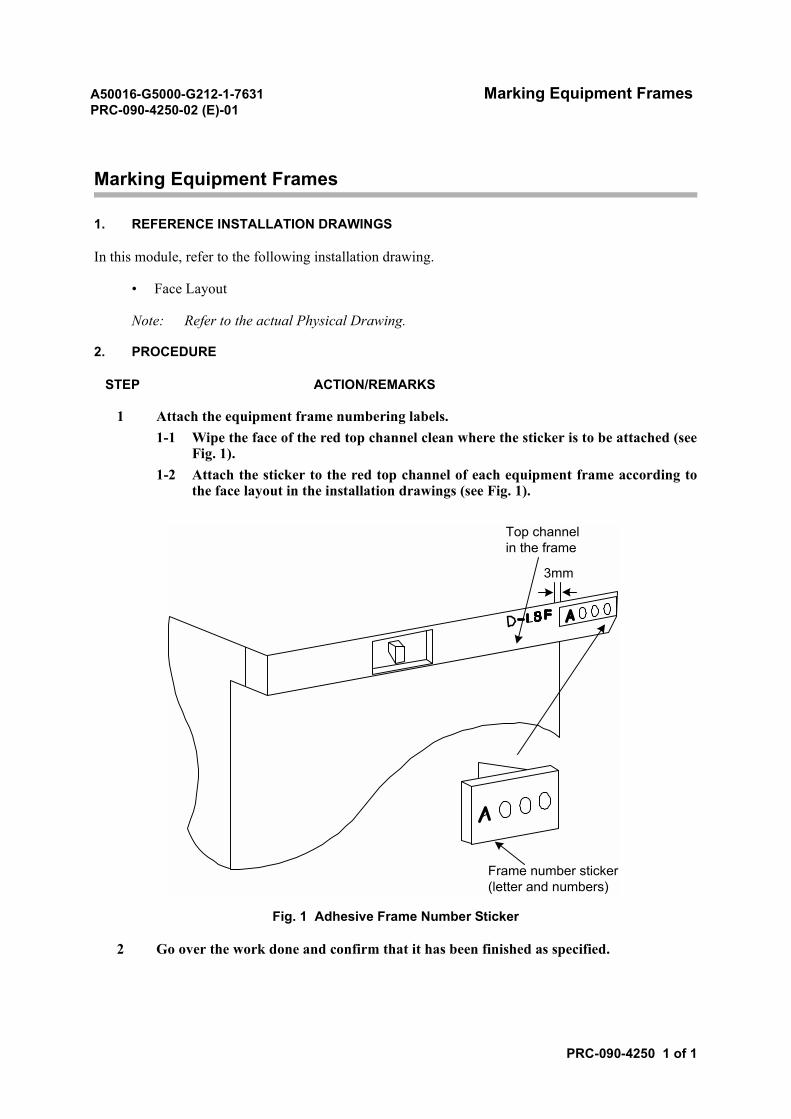
A50016-G5000-G212-1-7631 Marking Equipment FramesPRC-090-4250-02 (E)-01
PRC-090-4250 1 of 1
Marking Equipment Frames
1. REFERENCE INSTALLATION DRAWINGS
In this module, refer to the following installation drawing.
• Face Layout
Note: Refer to the actual Physical Drawing.
2. PROCEDURE
STEP ACTION/REMARKS
1 Attach the equipment frame numbering labels.1-1 Wipe the face of the red top channel clean where the sticker is to be attached (see
Fig. 1).1-2 Attach the sticker to the red top channel of each equipment frame according to
the face layout in the installation drawings (see Fig. 1).
Fig. 1 Adhesive Frame Number Sticker
2 Go over the work done and confirm that it has been finished as specified.
Top channelin the frame
3mm
Frame number sticker(letter and numbers)
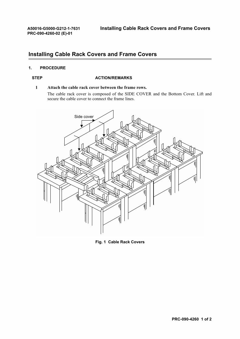
A50016-G5000-G212-1-7631 Installing Cable Rack Covers and Frame CoversPRC-090-4260-02 (E)-01
PRC-090-4260 1 of 2
Installing Cable Rack Covers and Frame Covers
1. PROCEDURE
STEP ACTION/REMARKS
1 Attach the cable rack cover between the frame rows.The cable rack cover is composed of the SIDE COVER and the Bottom Cover. Lift andsecure the cable cover to connect the frame lines.
Fig. 1 Cable Rack Covers
Side cover
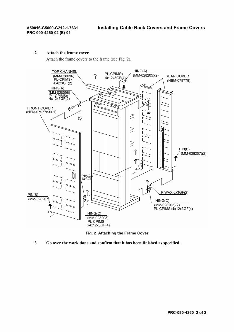
A50016-G5000-G212-1-7631 Installing Cable Rack Covers and Frame CoversPRC-090-4260-02 (E)-01
PRC-090-4260 2 of 2
2 Attach the frame cover.Attach the frame covers to the frame (see Fig. 2).
Fig. 2 Attaching the Frame Cover
3 Go over the work done and confirm that it has been finished as specified.
FRONT COVER(NEM-079778-001)
TOP CHANNEL(MM-028096)PL-CPIMSx4x8x3GF(2)
HING(A)(MM-028096)PL-CPIMSx4x12x3GF(2)
HING(A)(MM-028205)(2) REAR COVER
(NBM-079779)
PL-CPIMSx4x12x3GF(4)
PIN(B)(MM-028207)(2)
HING(C)(MM-028203)(2)PL-CPIMSx4x12x3GF(4)
PIN(B)(MM-028207)
HING(C)(MM-028203)PL-CPIMSx4x12x3GF(4)
PIWAX6x3GF
PIWAX 6x3GF(2)
A50016-G5000-G212-1-7631 Ethernet Cable LayingPRC-090-4270-02 (E)-01
PRC-090-4270 1 of 4
Ethernet Cable Laying
1. REFERENCE INSTALLATION DRAWINGS
In this module, refer to the following installation drawing.
• Cable Running List
Note: Refer to the actual Installation Drawing.
2. PROCEDURE
STEP ACTION/REMARKS
1 Assign personnel for each position on the cable laying route(see Fig. 1).• Supervising overall work• Cable running and forming to the frame in the switching room• Cable running, forming and tying at the cable support on the frame• Cable forming at the vertical cable rack• Cable running on the cable rackNote: common part of rack 47m
longest cable 70m
Fig. 1 Personnel Assignment for Ethernet Cable Laying (Example)
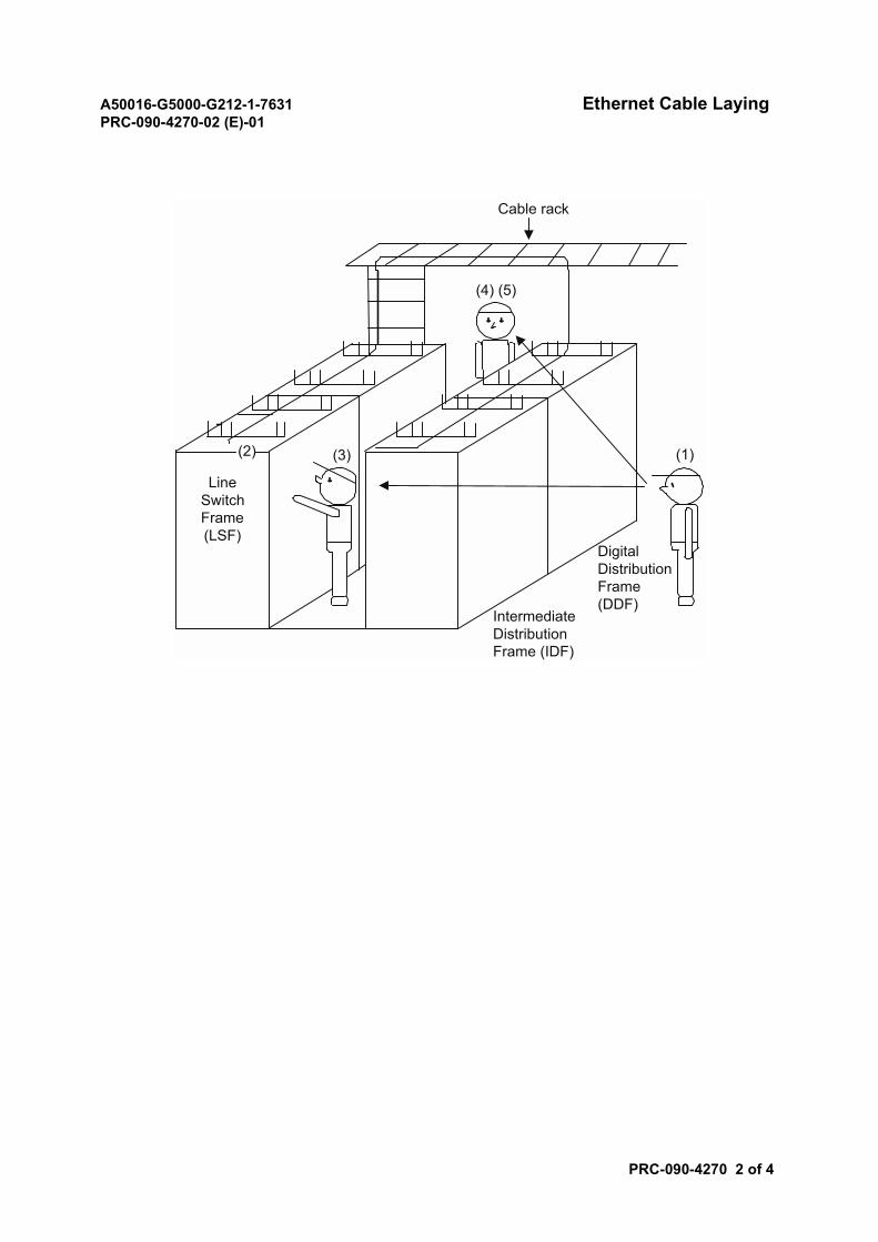
A50016-G5000-G212-1-7631 Ethernet Cable LayingPRC-090-4270-02 (E)-01
PRC-090-4270 2 of 4
(2)
LineSwitchFrame(LSF)
(3)
(4) (5)
Cable rack
IntermediateDistributionFrame (IDF)
DigitalDistributionFrame(DDF)
(1)
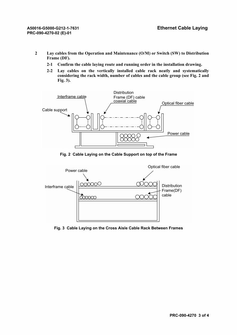
A50016-G5000-G212-1-7631 Ethernet Cable LayingPRC-090-4270-02 (E)-01
PRC-090-4270 3 of 4
2 Lay cables from the Operation and Maintenance (O/M) or Switch (SW) to DistributionFrame (DF).2-1 Confirm the cable laying route and running order in the installation drawing.2-2 Lay cables on the vertically installed cable rack neatly and systematically
considering the rack width, number of cables and the cable group (see Fig. 2 andFig. 3).
Fig. 2 Cable Laying on the Cable Support on top of the Frame
Fig. 3 Cable Laying on the Cross Aisle Cable Rack Between Frames
Interframe cable
Cable support
DistributionFrame (DF) cablecoaxial cable Optical fiber cable
Power cable
Optical fiber cablePower cable
Interframe cable DistributionFrame(DF)cable
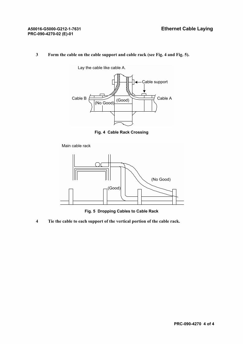
A50016-G5000-G212-1-7631 Ethernet Cable LayingPRC-090-4270-02 (E)-01
PRC-090-4270 4 of 4
3 Form the cable on the cable support and cable rack (see Fig. 4 and Fig. 5).
Fig. 4 Cable Rack Crossing
Fig. 5 Dropping Cables to Cable Rack
4 Tie the cable to each support of the vertical portion of the cable rack.
Cable support
Cable ACable B(No Good)
(Good)
Lay the cable like cable A.
Main cable rack
(Good)
(No Good)

A50016-G5000-G212-1-7631ND-57268-706 (E)-01
SECTION 6WORK FOR CABLE RACK INSTALLATION
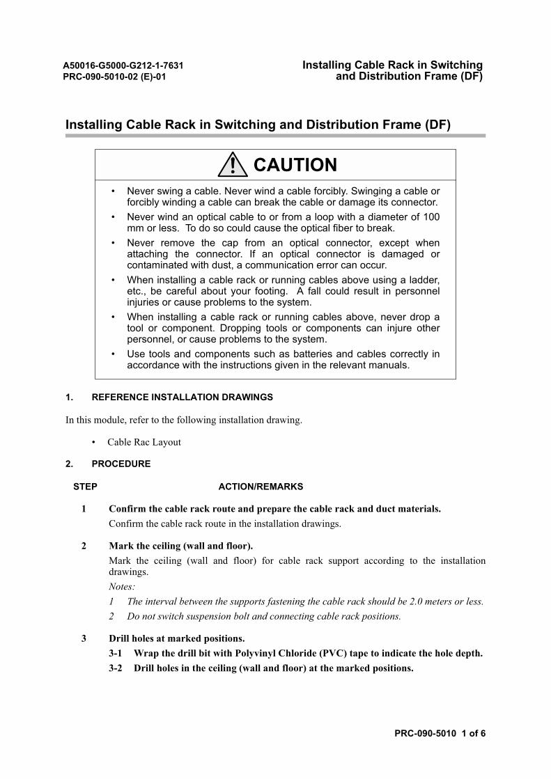
A50016-G5000-G212-1-7631 Installing Cable Rack in SwitchingPRC-090-5010-02 (E)-01 and Distribution Frame (DF)
PRC-090-5010 1 of 6
Installing Cable Rack in Switching and Distribution Frame (DF)
1. REFERENCE INSTALLATION DRAWINGS
In this module, refer to the following installation drawing.
• Cable Rac Layout
2. PROCEDURE
STEP ACTION/REMARKS
1 Confirm the cable rack route and prepare the cable rack and duct materials.Confirm the cable rack route in the installation drawings.
2 Mark the ceiling (wall and floor).Mark the ceiling (wall and floor) for cable rack support according to the installationdrawings.Notes:1 The interval between the supports fastening the cable rack should be 2.0 meters or less.2 Do not switch suspension bolt and connecting cable rack positions.
3 Drill holes at marked positions.3-1 Wrap the drill bit with Polyvinyl Chloride (PVC) tape to indicate the hole depth.3-2 Drill holes in the ceiling (wall and floor) at the marked positions.
CAUTION• Never swing a cable. Never wind a cable forcibly. Swinging a cable or
forcibly winding a cable can break the cable or damage its connector.• Never wind an optical cable to or from a loop with a diameter of 100
mm or less. To do so could cause the optical fiber to break.• Never remove the cap from an optical connector, except when
attaching the connector. If an optical connector is damaged orcontaminated with dust, a communication error can occur.
• When installing a cable rack or running cables above using a ladder,etc., be careful about your footing. A fall could result in personnelinjuries or cause problems to the system.
• When installing a cable rack or running cables above, never drop atool or component. Dropping tools or components can injure otherpersonnel, or cause problems to the system.
• Use tools and components such as batteries and cables correctly inaccordance with the instructions given in the relevant manuals.
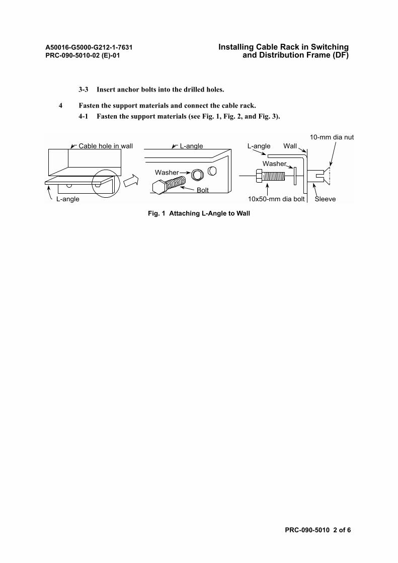
A50016-G5000-G212-1-7631 Installing Cable Rack in SwitchingPRC-090-5010-02 (E)-01 and Distribution Frame (DF)
PRC-090-5010 2 of 6
3-3 Insert anchor bolts into the drilled holes.
4 Fasten the support materials and connect the cable rack.4-1 Fasten the support materials (see Fig. 1, Fig. 2, and Fig. 3).
Fig. 1 Attaching L-Angle to Wall
10-mm dia nutCable hole in wall L-angle L-angle Wall
WasherWasher
BoltL-angle 10x50-mm dia bolt Sleeve
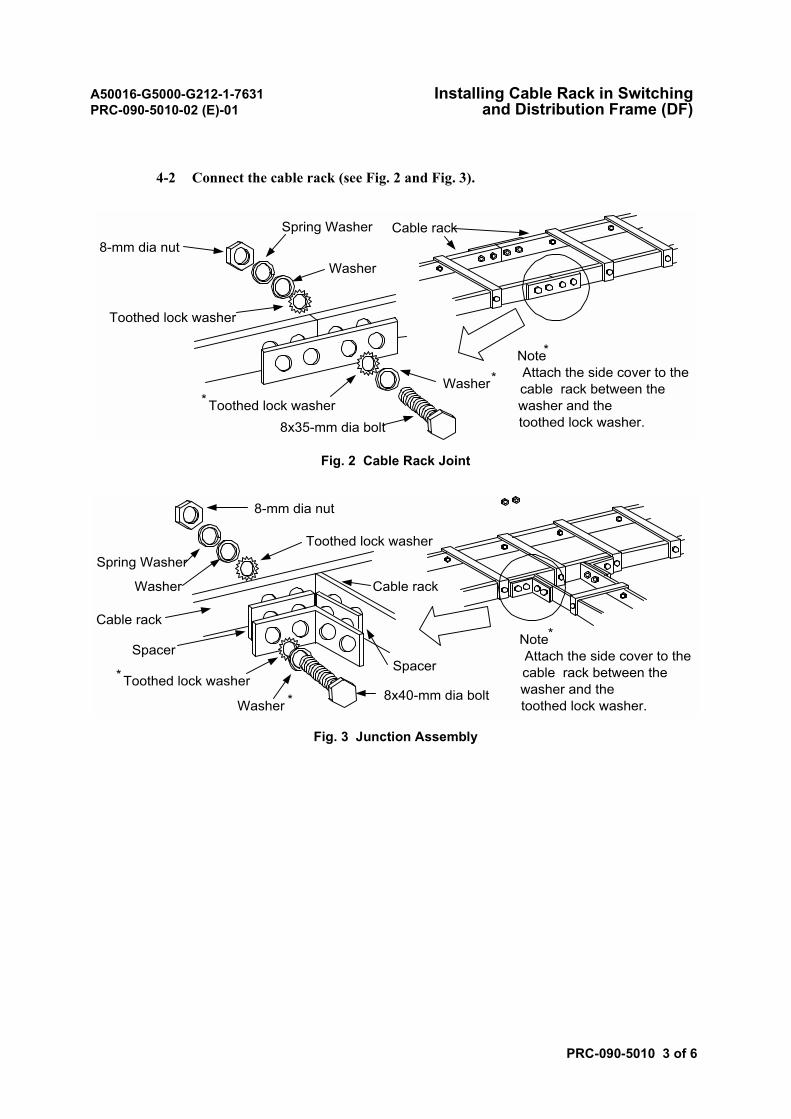
A50016-G5000-G212-1-7631 Installing Cable Rack in SwitchingPRC-090-5010-02 (E)-01 and Distribution Frame (DF)
PRC-090-5010 3 of 6
4-2 Connect the cable rack (see Fig. 2 and Fig. 3).
Fig. 2 Cable Rack Joint
Fig. 3 Junction Assembly
Note*
Attach the side cover to thecable rack between thewasher and thetoothed lock washer.
8-mm dia nutSpring Washer
* Toothed lock washerWasher*
Washer
Toothed lock washer
8x35-mm dia bolt
Cable rack
Spring WasherToothed lock washer
Washer
8x40-mm dia boltWasher *
* Toothed lock washer
8-mm dia nut
Note*
Attach the side cover to thecable rack between thewasher and thetoothed lock washer.
Cable rack
SpacerSpacer
Cable rack
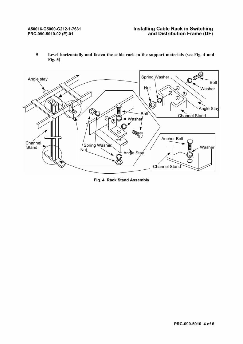
A50016-G5000-G212-1-7631 Installing Cable Rack in SwitchingPRC-090-5010-02 (E)-01 and Distribution Frame (DF)
PRC-090-5010 4 of 6
5 Level horizontally and fasten the cable rack to the support materials (see Fig. 4 andFig. 5)
Fig. 4 Rack Stand Assembly
ChannelStand Washer
Anchor Bolt
Channel Stand
Angle stay
Spring WasherNut
Washer
BoltWasher
Angle Stay
Channel Stand
Spring Washer
Nut
Bolt
Angle Stay
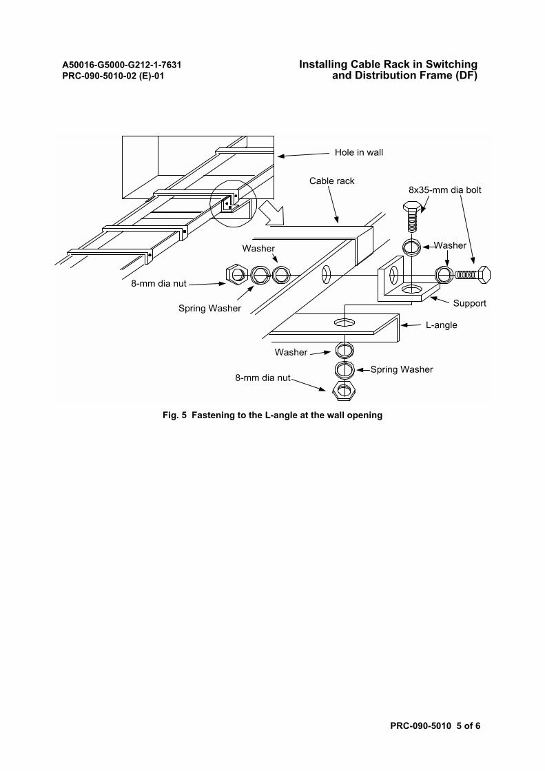
A50016-G5000-G212-1-7631 Installing Cable Rack in SwitchingPRC-090-5010-02 (E)-01 and Distribution Frame (DF)
PRC-090-5010 5 of 6
Fig. 5 Fastening to the L-angle at the wall opening
8-mm dia nut
Spring Washer
Hole in wall
8x35-mm dia bolt
Washer
Cable rack
Washer
Washer
Spring Washer8-mm dia nut
Support
L-angle
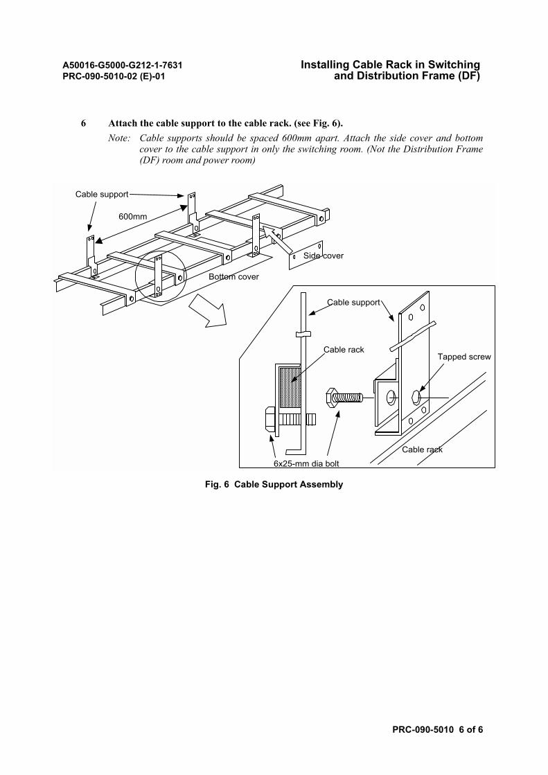
A50016-G5000-G212-1-7631 Installing Cable Rack in SwitchingPRC-090-5010-02 (E)-01 and Distribution Frame (DF)
PRC-090-5010 6 of 6
6 Attach the cable support to the cable rack. (see Fig. 6).Note: Cable supports should be spaced 600mm apart. Attach the side cover and bottom
cover to the cable support in only the switching room. (Not the Distribution Frame(DF) room and power room)
Fig. 6 Cable Support Assembly
600mm
6x25-mm dia bolt
Cable support
Tapped screw
Cable support
Cable rack
Bottom cover
Side cover
Cable rack

A50016-G5000-G212-1-7631ND-57268-706 (E)-01
SECTION 7TECHNICAL SUPPLEMENT
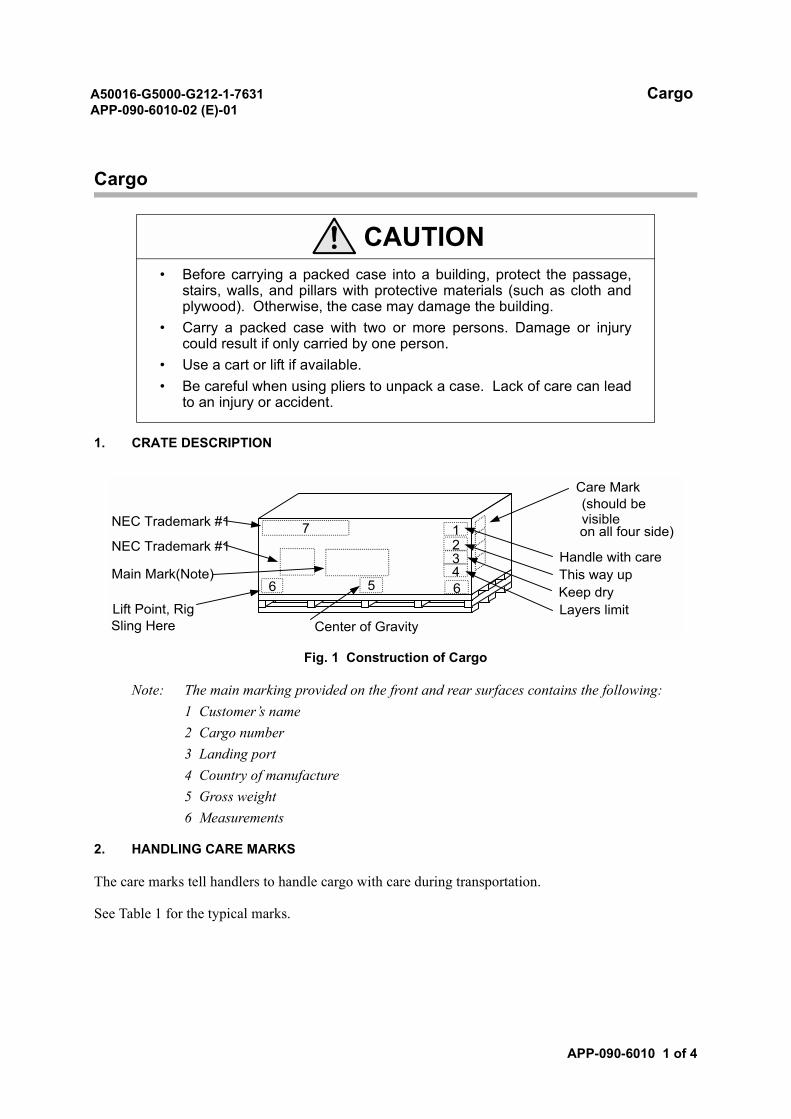
A50016-G5000-G212-1-7631 CargoAPP-090-6010-02 (E)-01
APP-090-6010 1 of 4
Cargo
1. CRATE DESCRIPTION
Fig. 1 Construction of Cargo
Note: The main marking provided on the front and rear surfaces contains the following:1 Customer’s name2 Cargo number3 Landing port4 Country of manufacture5 Gross weight6 Measurements
2. HANDLING CARE MARKS
The care marks tell handlers to handle cargo with care during transportation.
See Table 1 for the typical marks.
CAUTION• Before carrying a packed case into a building, protect the passage,
stairs, walls, and pillars with protective materials (such as cloth andplywood). Otherwise, the case may damage the building.
• Carry a packed case with two or more persons. Damage or injurycould result if only carried by one person.
• Use a cart or lift if available.• Be careful when using pliers to unpack a case. Lack of care can lead
to an injury or accident.
Handle with careThis way upKeep dryLayers limit
6 65
7 1234
Center of GravityLift Point, RigSling Here
Care Mark(should bevisibleon all four side)
Main Mark(Note)
NEC Trademark #1
NEC Trademark #1
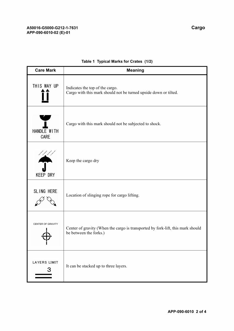
A50016-G5000-G212-1-7631 CargoAPP-090-6010-02 (E)-01
APP-090-6010 2 of 4
Table 1 Typical Marks for Crates (1/2)
Care Mark Meaning
Indicates the top of the cargo.Cargo with this mark should not be turned upside down or tilted.
Cargo with this mark should not be subjected to shock.
Keep the cargo dry
Location of slinging rope for cargo lifting.
Center of gravity (When the cargo is transported by fork-lift, this mark should be between the forks.)
It can be stacked up to three layers.
THIS WAY UP
HANDLE WITHCARE
KEEP DRY
SLING HERE
CENTER OF GRAVITY
3
LAYERS LIMIT

A50016-G5000-G212-1-7631 CargoAPP-090-6010-02 (E)-01
APP-090-6010 3 of 4
CE marking.
Table 1 Typical Marks for Crates (2/2)
Care Mark Meaning
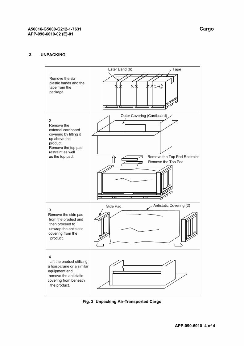
A50016-G5000-G212-1-7631 CargoAPP-090-6010-02 (E)-01
APP-090-6010 4 of 4
3. UNPACKING
Fig. 2 Unpacking Air-Transported Cargo
1Remove the sixplastic bands and thetape from thepackage.
2Remove theexternal cardboardcovering by lifting itup above theproduct.Remove the top padrestraint as wellas the top pad.
3Remove the side padfrom the product andthen proceed tounwrap the antistaticcovering from theproduct.
4Lift the product utilizing
a hoist-crane or a similarequipment andremove the antistatic
covering from beneaththe product.
Ester Band (6) Tape
Outer Covering (Cardboard)
Remove the Top Pad RestraintRemove the Top Pad
Side Pad Antistatic Covering (2)
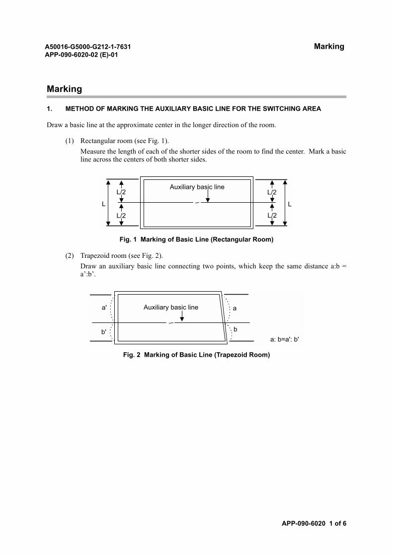
A50016-G5000-G212-1-7631 MarkingAPP-090-6020-02 (E)-01
APP-090-6020 1 of 6
Marking
1. METHOD OF MARKING THE AUXILIARY BASIC LINE FOR THE SWITCHING AREA
Draw a basic line at the approximate center in the longer direction of the room.
(1) Rectangular room (see Fig. 1).Measure the length of each of the shorter sides of the room to find the center. Mark a basicline across the centers of both shorter sides.
Fig. 1 Marking of Basic Line (Rectangular Room)
(2) Trapezoid room (see Fig. 2).Draw an auxiliary basic line connecting two points, which keep the same distance a:b =a’:b’.
Fig. 2 Marking of Basic Line (Trapezoid Room)
L L
L/2
L/2
L/2
L/2
Auxiliary basic line
a'
b'
a
b
Auxiliary basic line
a: b=a': b'
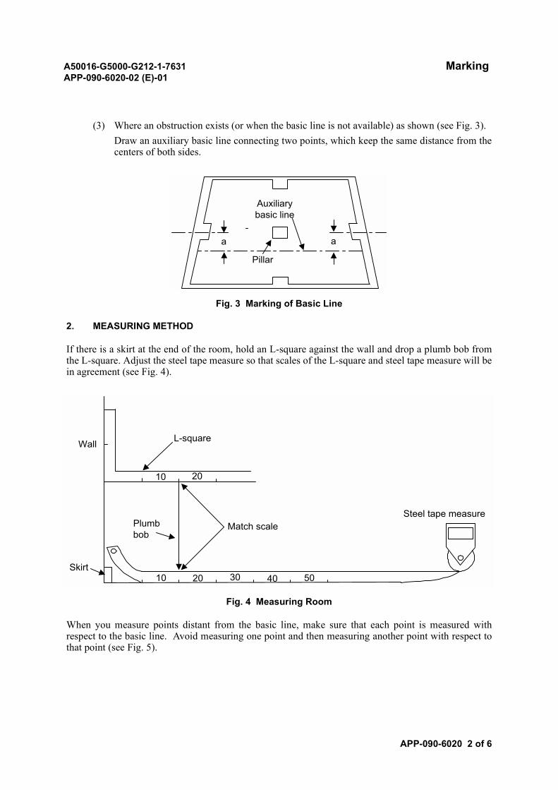
A50016-G5000-G212-1-7631 MarkingAPP-090-6020-02 (E)-01
APP-090-6020 2 of 6
(3) Where an obstruction exists (or when the basic line is not available) as shown (see Fig. 3).Draw an auxiliary basic line connecting two points, which keep the same distance from thecenters of both sides.
Fig. 3 Marking of Basic Line
2. MEASURING METHOD
If there is a skirt at the end of the room, hold an L-square against the wall and drop a plumb bob fromthe L-square. Adjust the steel tape measure so that scales of the L-square and steel tape measure will bein agreement (see Fig. 4).
Fig. 4 Measuring Room
When you measure points distant from the basic line, make sure that each point is measured withrespect to the basic line. Avoid measuring one point and then measuring another point with respect tothat point (see Fig. 5).
Auxiliarybasic line
a a
Pillar
L-square
Match scalePlumbbob
10 20
Wall
10 20 30 40 50Skirt
Steel tape measure
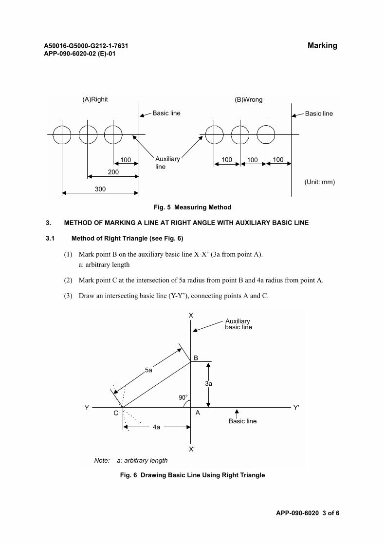
A50016-G5000-G212-1-7631 MarkingAPP-090-6020-02 (E)-01
APP-090-6020 3 of 6
Fig. 5 Measuring Method
3. METHOD OF MARKING A LINE AT RIGHT ANGLE WITH AUXILIARY BASIC LINE
3.1 Method of Right Triangle (see Fig. 6)
(1) Mark point B on the auxiliary basic line X-X’ (3a from point A).a: arbitrary length
(2) Mark point C at the intersection of 5a radius from point B and 4a radius from point A.
(3) Draw an intersecting basic line (Y-Y’), connecting points A and C.
Fig. 6 Drawing Basic Line Using Right Triangle
(A)Righit (B)Wrong
Basic line
Auxiliaryline
Basic line
100 100 100100
200
300(Unit: mm)
Auxiliarybasic line
X
B
3a
90°
5a
4a
AY'
X'
CY
Basic line
Note: a: arbitrary length
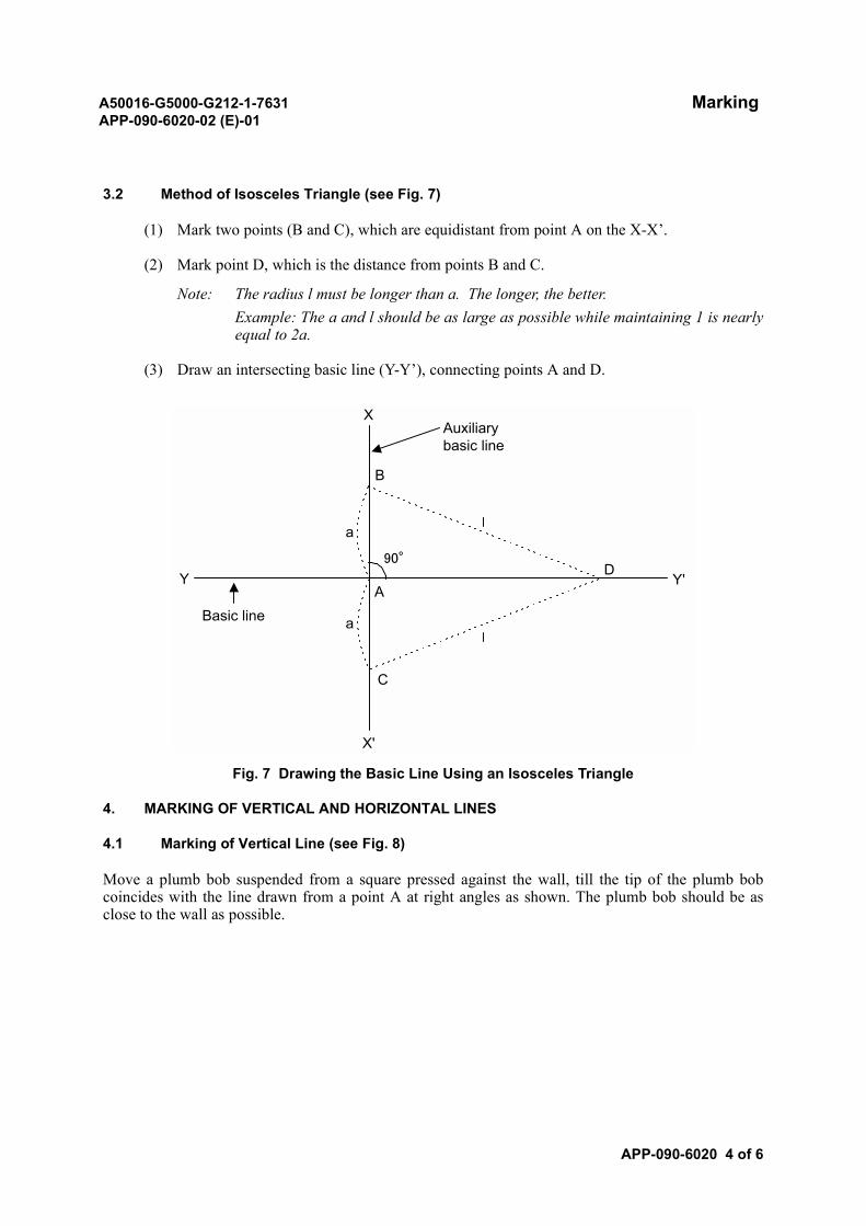
A50016-G5000-G212-1-7631 MarkingAPP-090-6020-02 (E)-01
APP-090-6020 4 of 6
3.2 Method of Isosceles Triangle (see Fig. 7)
(1) Mark two points (B and C), which are equidistant from point A on the X-X’.
(2) Mark point D, which is the distance from points B and C.
Note: The radius l must be longer than a. The longer, the better.Example: The a and l should be as large as possible while maintaining 1 is nearlyequal to 2a.
(3) Draw an intersecting basic line (Y-Y’), connecting points A and D.
Fig. 7 Drawing the Basic Line Using an Isosceles Triangle
4. MARKING OF VERTICAL AND HORIZONTAL LINES
4.1 Marking of Vertical Line (see Fig. 8)
Move a plumb bob suspended from a square pressed against the wall, till the tip of the plumb bobcoincides with the line drawn from a point A at right angles as shown. The plumb bob should be asclose to the wall as possible.
Basic line
Y
B
X
a
a
A
C
DY'
X'
90°
Auxiliarybasic line
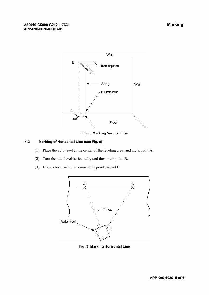
A50016-G5000-G212-1-7631 MarkingAPP-090-6020-02 (E)-01
APP-090-6020 5 of 6
Fig. 8 Marking Vertical Line
4.2 Marking of Horizontal Line (see Fig. 9)
(1) Place the auto level at the center of the leveling area, and mark point A.
(2) Turn the auto level horizontally and then mark point B.
(3) Draw a horizontal line connecting points A and B.
Fig. 9 Marking Horizontal Line
B
Wall
Wall
Floor
A
Iron square
Sting
Plumb bob
90°
Auto level
A B
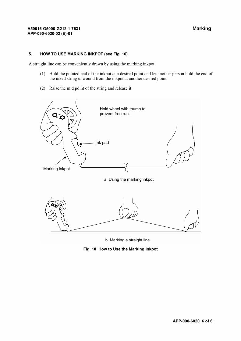
A50016-G5000-G212-1-7631 MarkingAPP-090-6020-02 (E)-01
APP-090-6020 6 of 6
5. HOW TO USE MARKING INKPOT (see Fig. 10)
A straight line can be conveniently drawn by using the marking inkpot.
(1) Hold the pointed end of the inkpot at a desired point and let another person hold the end ofthe inked string unwound from the inkpot at another desired point.
(2) Raise the mid point of the string and release it.
Fig. 10 How to Use the Marking Inkpot
Hold wheel with thumb toprevent free run.
Marking inkpot
Ink pad
a. Using the marking inkpot
b. Marking a straight line
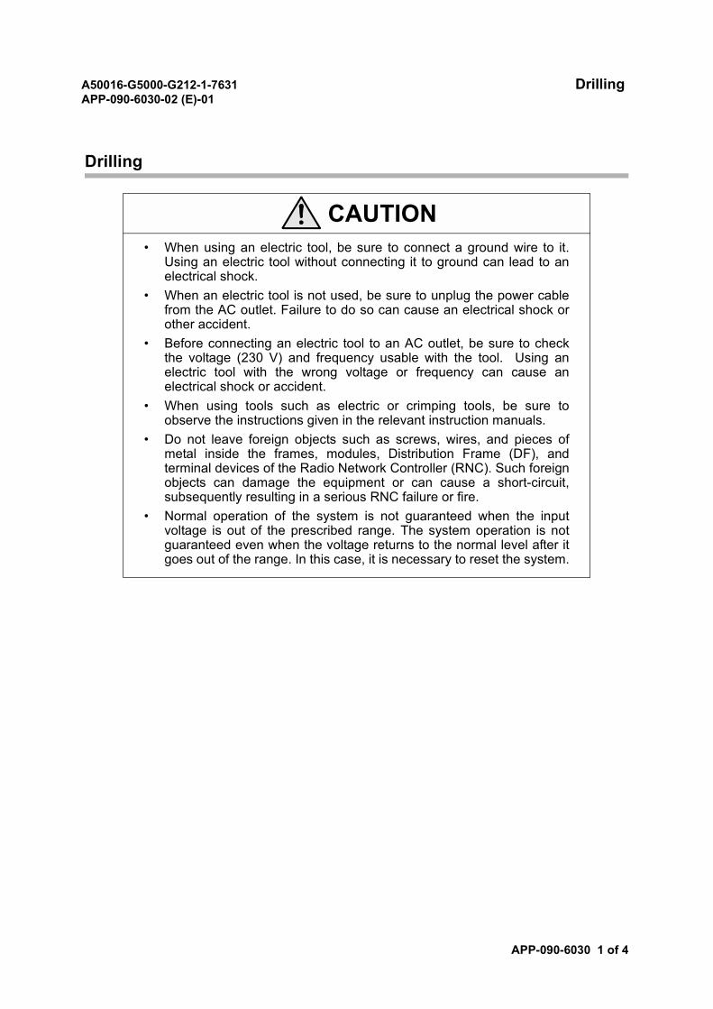
A50016-G5000-G212-1-7631 DrillingAPP-090-6030-02 (E)-01
APP-090-6030 1 of 4
Drilling
CAUTION• When using an electric tool, be sure to connect a ground wire to it.
Using an electric tool without connecting it to ground can lead to anelectrical shock.
• When an electric tool is not used, be sure to unplug the power cablefrom the AC outlet. Failure to do so can cause an electrical shock orother accident.
• Before connecting an electric tool to an AC outlet, be sure to checkthe voltage (230 V) and frequency usable with the tool. Using anelectric tool with the wrong voltage or frequency can cause anelectrical shock or accident.
• When using tools such as electric or crimping tools, be sure toobserve the instructions given in the relevant instruction manuals.
• Do not leave foreign objects such as screws, wires, and pieces ofmetal inside the frames, modules, Distribution Frame (DF), andterminal devices of the Radio Network Controller (RNC). Such foreignobjects can damage the equipment or can cause a short-circuit,subsequently resulting in a serious RNC failure or fire.
• Normal operation of the system is not guaranteed when the inputvoltage is out of the prescribed range. The system operation is notguaranteed even when the voltage returns to the normal level after itgoes out of the range. In this case, it is necessary to reset the system.
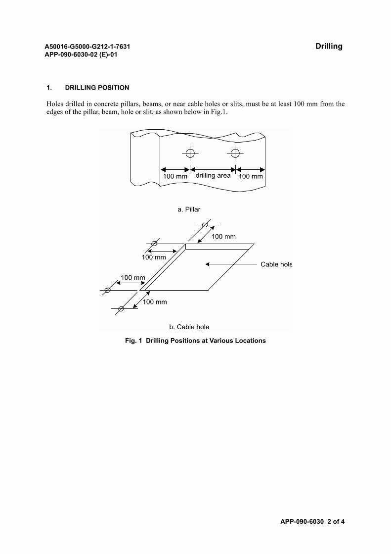
A50016-G5000-G212-1-7631 DrillingAPP-090-6030-02 (E)-01
APP-090-6030 2 of 4
1. DRILLING POSITION
Holes drilled in concrete pillars, beams, or near cable holes or slits, must be at least 100 mm from theedges of the pillar, beam, hole or slit, as shown below in Fig.1.
Fig. 1 Drilling Positions at Various Locations
a. Pillar
100 mm
100 mm
Cable hole
100 mm
100 mm
b. Cable hole
drilling area100 mm 100 mm
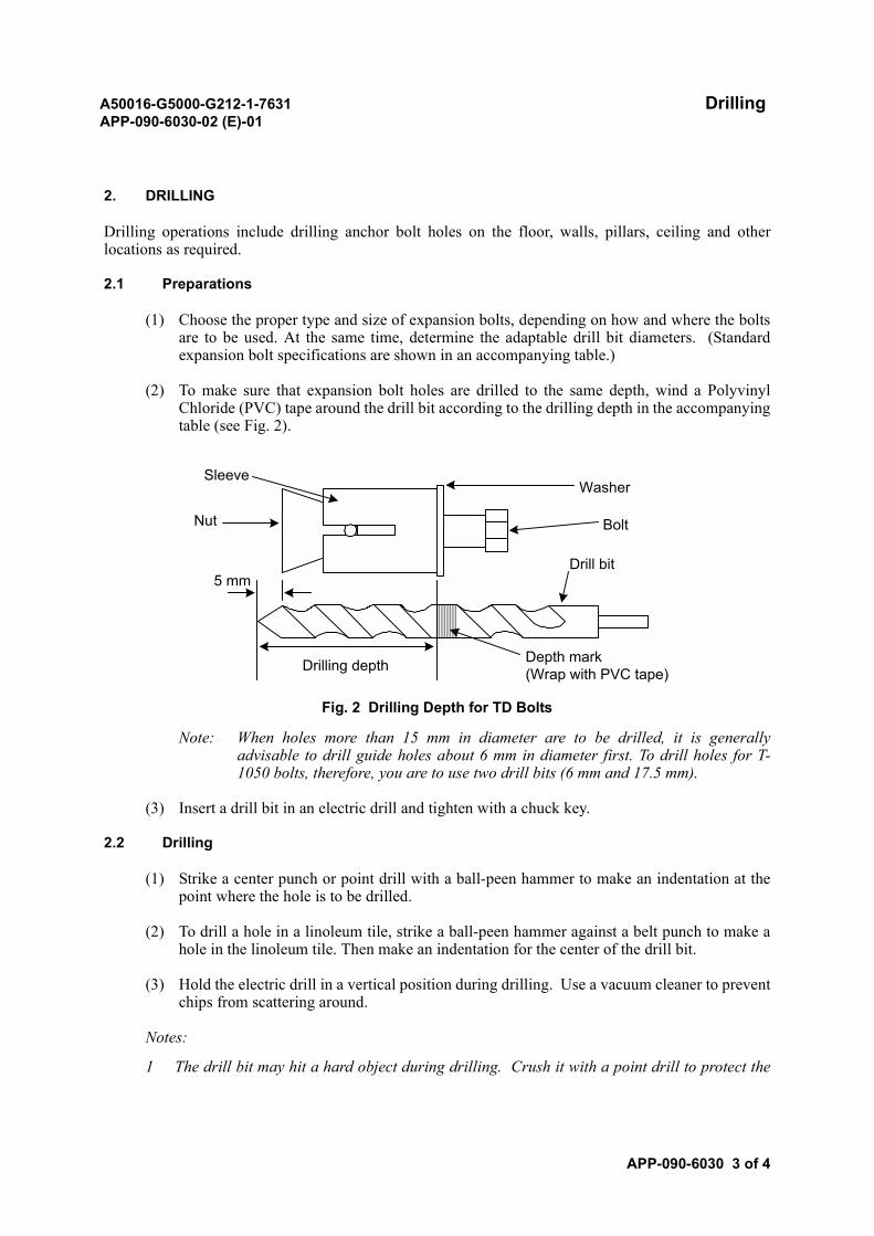
A50016-G5000-G212-1-7631 DrillingAPP-090-6030-02 (E)-01
APP-090-6030 3 of 4
2. DRILLING
Drilling operations include drilling anchor bolt holes on the floor, walls, pillars, ceiling and otherlocations as required.
2.1 Preparations
(1) Choose the proper type and size of expansion bolts, depending on how and where the boltsare to be used. At the same time, determine the adaptable drill bit diameters. (Standardexpansion bolt specifications are shown in an accompanying table.)
(2) To make sure that expansion bolt holes are drilled to the same depth, wind a PolyvinylChloride (PVC) tape around the drill bit according to the drilling depth in the accompanyingtable (see Fig. 2).
Fig. 2 Drilling Depth for TD Bolts
Note: When holes more than 15 mm in diameter are to be drilled, it is generallyadvisable to drill guide holes about 6 mm in diameter first. To drill holes for T-1050 bolts, therefore, you are to use two drill bits (6 mm and 17.5 mm).
(3) Insert a drill bit in an electric drill and tighten with a chuck key.
2.2 Drilling
(1) Strike a center punch or point drill with a ball-peen hammer to make an indentation at thepoint where the hole is to be drilled.
(2) To drill a hole in a linoleum tile, strike a ball-peen hammer against a belt punch to make ahole in the linoleum tile. Then make an indentation for the center of the drill bit.
(3) Hold the electric drill in a vertical position during drilling. Use a vacuum cleaner to preventchips from scattering around.
Notes:
1 The drill bit may hit a hard object during drilling. Crush it with a point drill to protect the
Sleeve
Nut
5 mm
Drilling depth
Washer
Bolt
Drill bit
Depth mark(Wrap with PVC tape)

A50016-G5000-G212-1-7631 DrillingAPP-090-6030-02 (E)-01
APP-090-6030 4 of 4
drill bit, then resume drilling thereafter.
2 If the drill bit overheats, let it cool down. Don’t use water or oil to cool it.
3 Use a vacuum cleaner to remove chips during drilling.
4 After finishing drilling, check the diameter and depth of the hole. Then insert an anchor bolt.
5 If the drilled hole is off center or oversized, insert a bolt in the center position and fill thegap with lead.
6 If the drilled hole is excessively large, fill the gap with lead calk or cement mortar.
7 The drill bit may hit a reinforcement bar (or any other hard object in the building) duringdrilling. Change the drilling point or take appropriate steps to prevent damage to the drillbit.
2.3 How to Use Anchor Bolts
An anchor bolt is gripped firmly in a drilled hole as described below.
(1) Use a drill bit equal to the anchor bolt in diameter. Drill a hole that is slightly deeper thanthe length of the anchor bolt.
(2) Insert the anchor bolt into the hole.
(3) Tighten the anchor bolt, thereby expanding the sleeve and fixing the bolt, and tighten down.
(4) Remove the bolt by turning it counter-clockwise.
(5) Center equipment to be bolted down over the opening, insert the bolt, and tighten down.
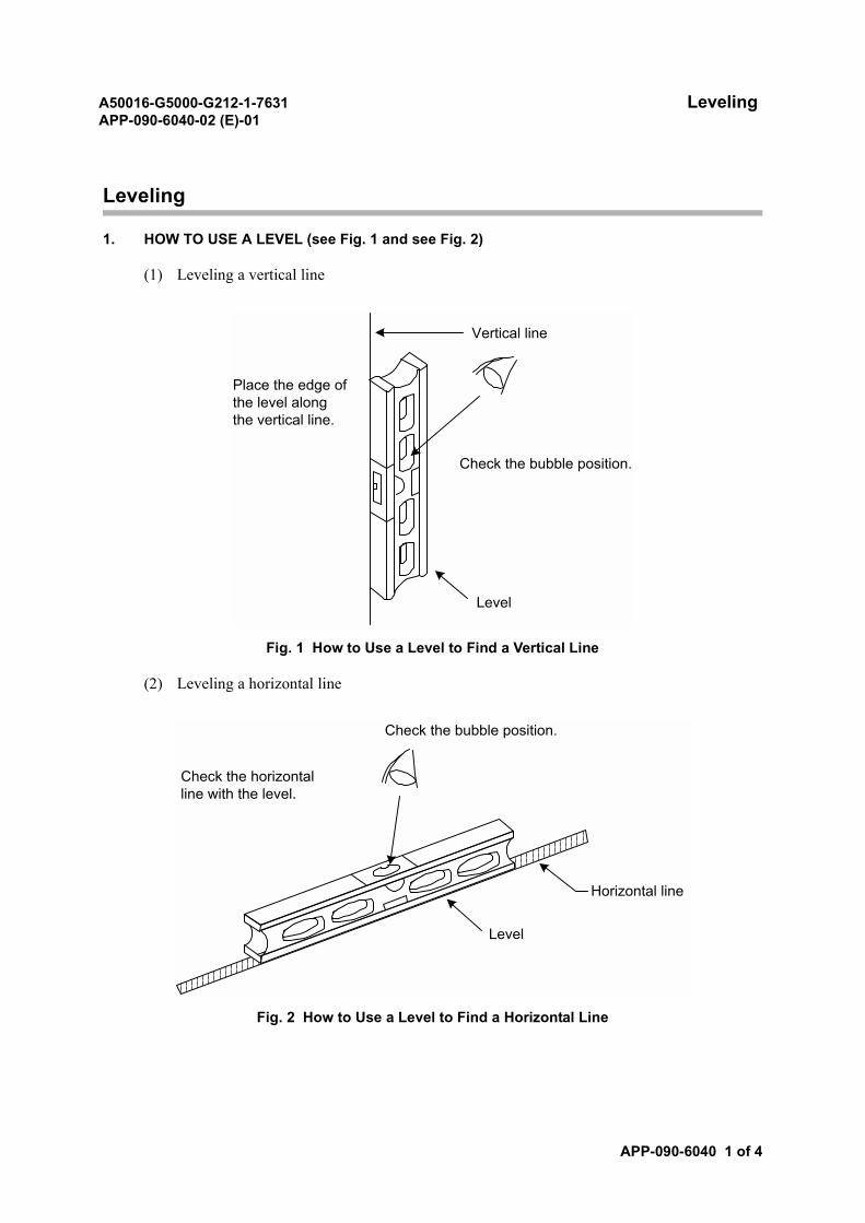
A50016-G5000-G212-1-7631 LevelingAPP-090-6040-02 (E)-01
APP-090-6040 1 of 4
Leveling
1. HOW TO USE A LEVEL (see Fig. 1 and see Fig. 2)
(1) Leveling a vertical line
Fig. 1 How to Use a Level to Find a Vertical Line
(2) Leveling a horizontal line
Fig. 2 How to Use a Level to Find a Horizontal Line
Level
Vertical line
Check the bubble position.
Place the edge ofthe level alongthe vertical line.
Check the bubble position.
Horizontal line
Level
Check the horizontalline with the level.
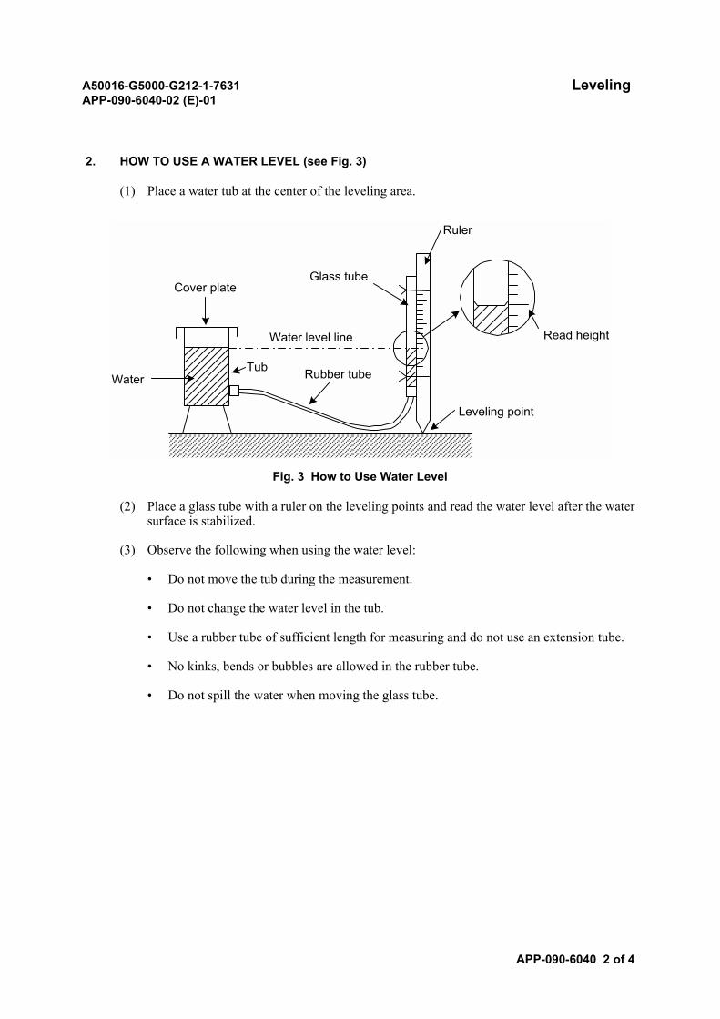
A50016-G5000-G212-1-7631 LevelingAPP-090-6040-02 (E)-01
APP-090-6040 2 of 4
2. HOW TO USE A WATER LEVEL (see Fig. 3)
(1) Place a water tub at the center of the leveling area.
Fig. 3 How to Use Water Level
(2) Place a glass tube with a ruler on the leveling points and read the water level after the watersurface is stabilized.
(3) Observe the following when using the water level:
• Do not move the tub during the measurement.
• Do not change the water level in the tub.
• Use a rubber tube of sufficient length for measuring and do not use an extension tube.
• No kinks, bends or bubbles are allowed in the rubber tube.
• Do not spill the water when moving the glass tube.
Ruler
Read height
Leveling point
WaterTub Rubber tube
Water level line
Cover plateGlass tube
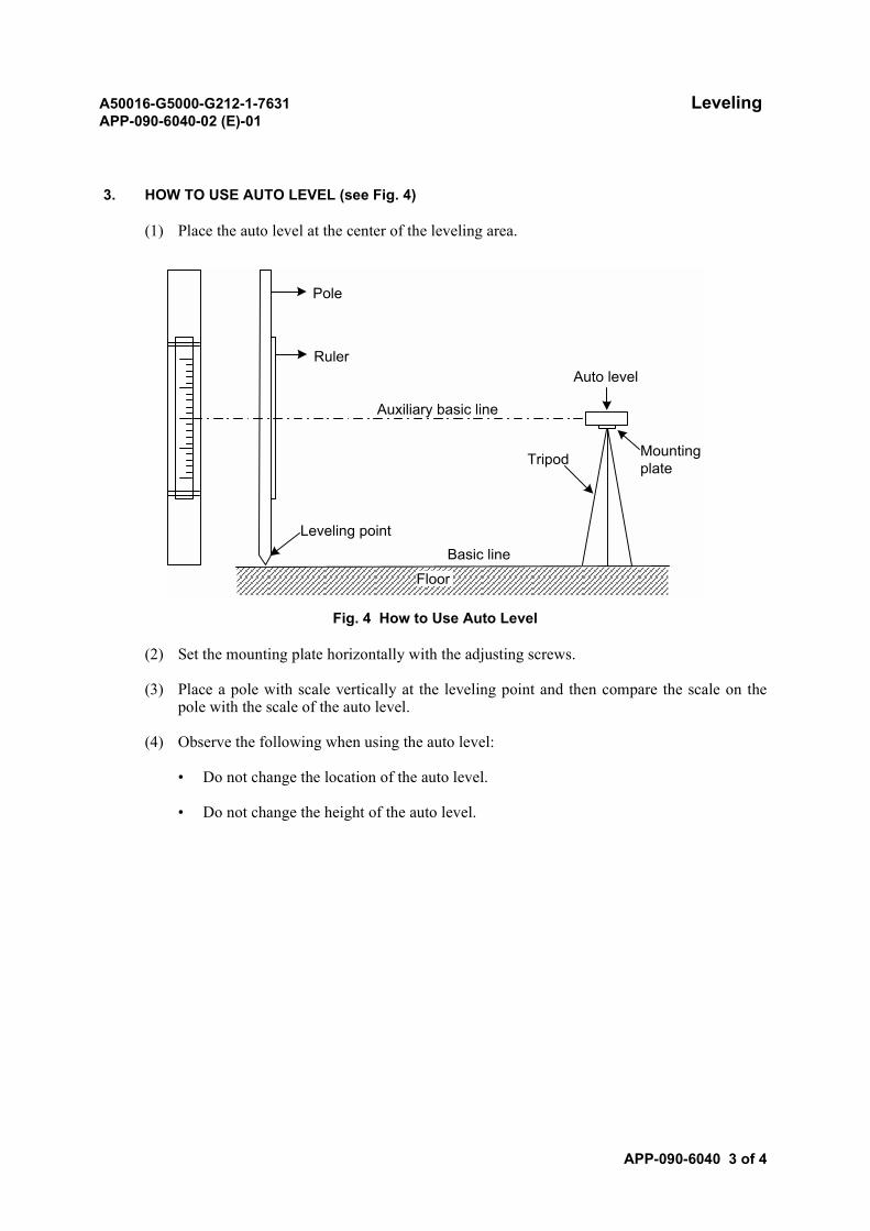
A50016-G5000-G212-1-7631 LevelingAPP-090-6040-02 (E)-01
APP-090-6040 3 of 4
3. HOW TO USE AUTO LEVEL (see Fig. 4)
(1) Place the auto level at the center of the leveling area.
Fig. 4 How to Use Auto Level
(2) Set the mounting plate horizontally with the adjusting screws.
(3) Place a pole with scale vertically at the leveling point and then compare the scale on thepole with the scale of the auto level.
(4) Observe the following when using the auto level:
• Do not change the location of the auto level.
• Do not change the height of the auto level.
Ruler
Leveling point
Floor
Basic line
Auxiliary basic line
Tripod
Auto level
Mountingplate
Pole
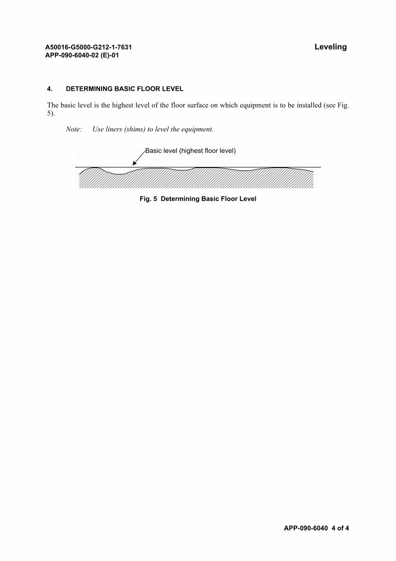
A50016-G5000-G212-1-7631 LevelingAPP-090-6040-02 (E)-01
APP-090-6040 4 of 4
4. DETERMINING BASIC FLOOR LEVEL
The basic level is the highest level of the floor surface on which equipment is to be installed (see Fig.5).
Note: Use liners (shims) to level the equipment.
Fig. 5 Determining Basic Floor Level
Basic level (highest floor level)
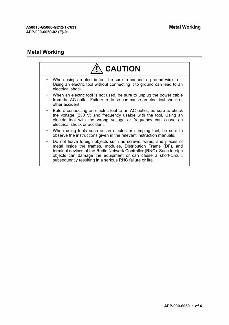
A50016-G5000-G212-1-7631 Metal WorkingAPP-090-6050-02 (E)-01
APP-090-6050 1 of 4
Metal Working
CAUTION• When using an electric tool, be sure to connect a ground wire to it.
Using an electric tool without connecting it to ground can lead to anelectrical shock.
• When an electric tool is not used, be sure to unplug the power cablefrom the AC outlet. Failure to do so can cause an electrical shock orother accident.
• Before connecting an electric tool to an AC outlet, be sure to checkthe voltage (230 V) and frequency usable with the tool. Using anelectric tool with the wrong voltage or frequency can cause anelectrical shock or accident.
• When using tools such as an electric or crimping tool, be sure toobserve the instructions given in the relevant instruction manuals.
• Do not leave foreign objects such as screws, wires, and pieces ofmetal inside the frames, modules, Distribution Frame (DF), andterminal devices of the Radio Network Controller (RNC). Such foreignobjects can damage the equipment or can cause a short-circuit,subsequently resulting in a serious RNC failure or fire.
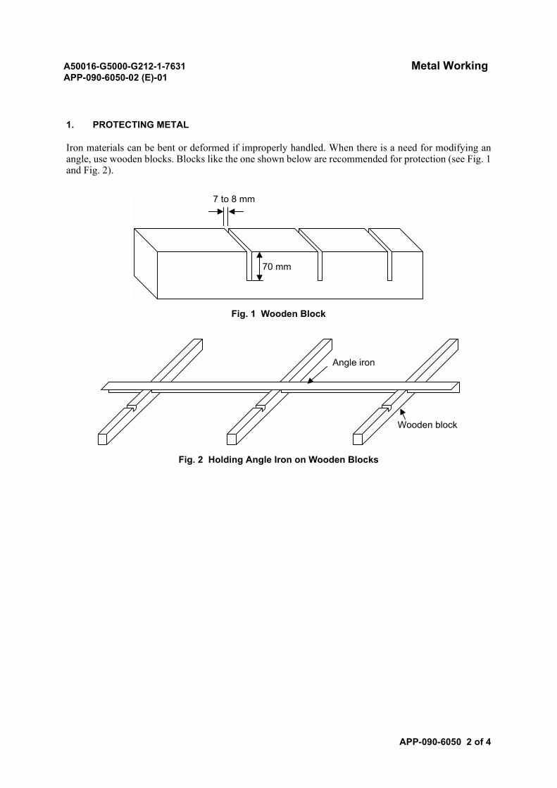
A50016-G5000-G212-1-7631 Metal WorkingAPP-090-6050-02 (E)-01
APP-090-6050 2 of 4
1. PROTECTING METAL
Iron materials can be bent or deformed if improperly handled. When there is a need for modifying anangle, use wooden blocks. Blocks like the one shown below are recommended for protection (see Fig. 1and Fig. 2).
Fig. 1 Wooden Block
Fig. 2 Holding Angle Iron on Wooden Blocks
70 mm
7 to 8 mm
Wooden block
Angle iron

A50016-G5000-G212-1-7631 Metal WorkingAPP-090-6050-02 (E)-01
APP-090-6050 3 of 4
2. METAL WORKING
When the metal must be cut or drilled, follow these steps:
(1) Mark the position on the material to be cut or drilled (see Fig. 3).
Fig. 3 Marking Metal
Mark with scribe
Scribe
Iron square
Iron square
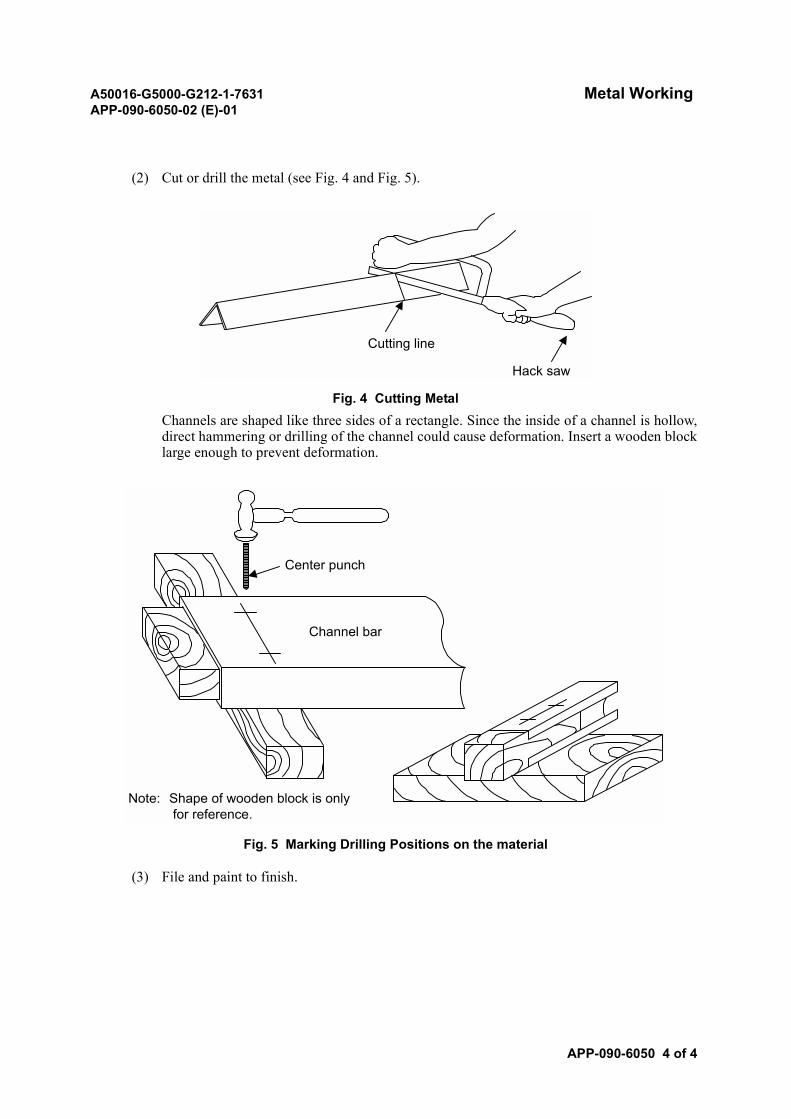
A50016-G5000-G212-1-7631 Metal WorkingAPP-090-6050-02 (E)-01
APP-090-6050 4 of 4
(2) Cut or drill the metal (see Fig. 4 and Fig. 5).
Fig. 4 Cutting MetalChannels are shaped like three sides of a rectangle. Since the inside of a channel is hollow,direct hammering or drilling of the channel could cause deformation. Insert a wooden blocklarge enough to prevent deformation.
Fig. 5 Marking Drilling Positions on the material
(3) File and paint to finish.
Cutting line
Hack saw
Channel bar
Center punch
Note: Shape of wooden block is only for reference.
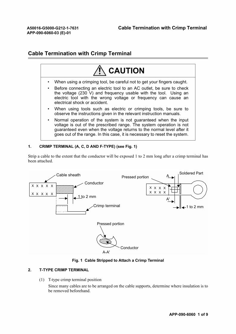
A50016-G5000-G212-1-7631 Cable Termination with Crimp TerminalAPP-090-6060-03 (E)-01
APP-090-6060 1 of 9
Cable Termination with Crimp Terminal
1. CRIMP TERMINAL (A, C, D AND F-TYPE) (see Fig. 1)
Strip a cable to the extent that the conductor will be exposed 1 to 2 mm long after a crimp terminal hasbeen attached.
Fig. 1 Cable Stripped to Attach a Crimp Terminal
2. T-TYPE CRIMP TERMINAL
(1) T-type crimp terminal positionSince many cables are to be arranged on the cable supports, determine where insulation is tobe removed beforehand.
CAUTION• When using a crimping tool, be careful not to get your fingers caught.• Before connecting an electric tool to an AC outlet, be sure to check
the voltage (230 V) and frequency usable with the tool. Using anelectric tool with the wrong voltage or frequency can cause anelectrical shock or accident.
• When using tools such as electric or crimping tools, be sure toobserve the instructions given in the relevant instruction manuals.
• Normal operation of the system is not guaranteed when the inputvoltage is out of the prescribed range. The system operation is notguaranteed even when the voltage returns to the normal level after itgoes out of the range. In this case, it is necessary to reset the system.
X X X XX X X X
Pressed portionSoldered Part
Pressed portion
1 to 2 mm
A
A'
A-A'Conductor
X X X X X
X X X X X
Cable sheath
Conductor
1 to 2 mm
Crimp terminal
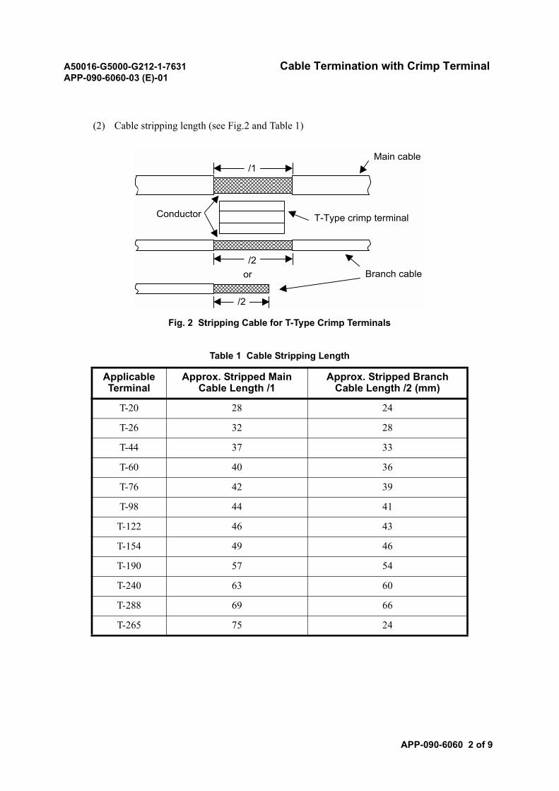
A50016-G5000-G212-1-7631 Cable Termination with Crimp TerminalAPP-090-6060-03 (E)-01
APP-090-6060 2 of 9
(2) Cable stripping length (see Fig.2 and Table 1)
Fig. 2 Stripping Cable for T-Type Crimp Terminals
Table 1 Cable Stripping Length
Applicable Terminal
Approx. Stripped Main Cable Length /1
Approx. Stripped Branch Cable Length /2 (mm)
T-20 28 24
T-26 32 28
T-44 37 33
T-60 40 36
T-76 42 39
T-98 44 41
T-122 46 43
T-154 49 46
T-190 57 54
T-240 63 60
T-288 69 66
T-265 75 24
or Branch cable
T-Type crimp terminalConductor
Main cable/1
/2
/2
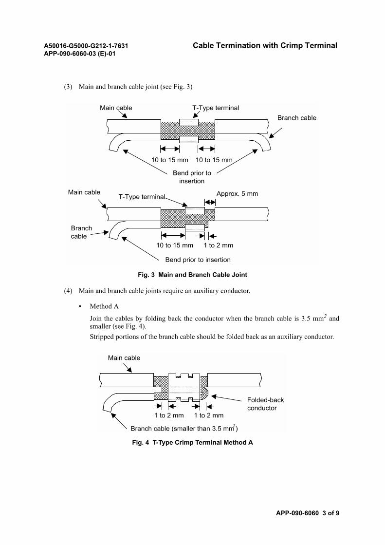
A50016-G5000-G212-1-7631 Cable Termination with Crimp TerminalAPP-090-6060-03 (E)-01
APP-090-6060 3 of 9
(3) Main and branch cable joint (see Fig. 3)
Fig. 3 Main and Branch Cable Joint
(4) Main and branch cable joints require an auxiliary conductor.
• Method A
Join the cables by folding back the conductor when the branch cable is 3.5 mm2 andsmaller (see Fig. 4).Stripped portions of the branch cable should be folded back as an auxiliary conductor.
Fig. 4 T-Type Crimp Terminal Method A
10 to 15 mm 10 to 15 mm
T-Type terminalMain cableBranch cable
Bend prior toinsertion
1 to 2 mm10 to 15 mm
T-Type terminalMain cable
Bend prior to insertion
Branchcable
Approx. 5 mm
Branch cable (smaller than 3.5 mm2)
1 to 2 mm
Main cable
1 to 2 mm
Folded-backconductor
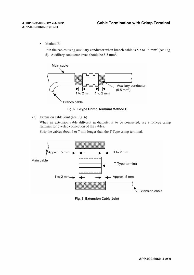
A50016-G5000-G212-1-7631 Cable Termination with Crimp TerminalAPP-090-6060-03 (E)-01
APP-090-6060 4 of 9
• Method B
Join the cables using auxiliary conductor when branch cable is 5.5 to 14 mm2 (see Fig.5). Auxiliary conductor areas should be 5.5 mm2.
Fig. 5 T-Type Crimp Terminal Method B
(5) Extension cable joint (see Fig. 6)When an extension cable different in diameter is to be connected, use a T-Type crimpterminal for overlap connection of the cables.Strip the cables about 6 or 7 mm longer than the T-Type crimp terminal.
Fig. 6 Extension Cable Joint
(5.5 mm )
Branch cable
1 to 2 mm
Main cable
1 to 2 mm
Auxiliary conductor2
T-Type terminal
1 to 2 mm
1 to 2 mm
Approx. 5 mm
Approx. 5 mm
Extension cable
Main cable
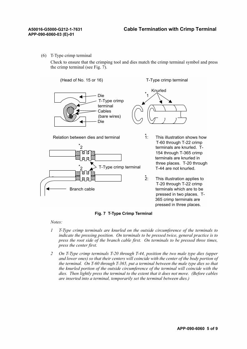
A50016-G5000-G212-1-7631 Cable Termination with Crimp TerminalAPP-090-6060-03 (E)-01
APP-090-6060 5 of 9
(6) T-Type crimp terminalCheck to ensure that the crimping tool and dies match the crimp terminal symbol and pressthe crimp terminal (see Fig. 7).
Fig. 7 T-Type Crimp Terminal
Notes:
1 T-Type crimp terminals are knurled on the outside circumference of the terminals toindicate the pressing position. On terminals to be pressed twice, general practice is topress the root side of the branch cable first. On terminals to be pressed three times,press the center first.
2 On T-Type crimp terminals T-20 through T-44, position the two male type dies (upperand lower ones) so that their centers will coincide with the center of the body portion ofthe terminal. On T-60 through T-365, put a terminal between the male type dies so thatthe knurled portion of the outside circumference of the terminal will coincide with thedies. Then lightly press the terminal to the extent that it does not move. (Before cablesare inserted into a terminal, temporarily set the terminal between dies.)
(Head of No. 15 or 16) T-Type crimp terminal
Die *1T-Type crimpterminalCables(bare wires)Die
Relation between dies and terminal *1: This illustration shows howT-60 through T-22 crimp
*2 terminals are knurled. T-154 through T-365 crimpterminals are knurled inthree places. T-20 through
*2 T-44 are not knurled.
*2: This illustration applies toT-20 through T-22 crimp
Branch cable terminals which are to bepressed in two places. T-365 crimp terminals arepressed in three places.
Knurled
T-Type crimp terminal
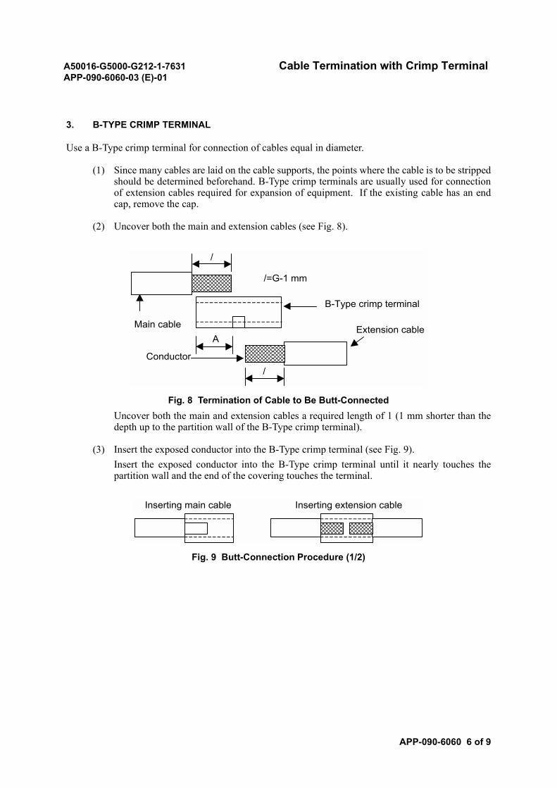
A50016-G5000-G212-1-7631 Cable Termination with Crimp TerminalAPP-090-6060-03 (E)-01
APP-090-6060 6 of 9
3. B-TYPE CRIMP TERMINAL
Use a B-Type crimp terminal for connection of cables equal in diameter.
(1) Since many cables are laid on the cable supports, the points where the cable is to be strippedshould be determined beforehand. B-Type crimp terminals are usually used for connectionof extension cables required for expansion of equipment. If the existing cable has an endcap, remove the cap.
(2) Uncover both the main and extension cables (see Fig. 8).
Fig. 8 Termination of Cable to Be Butt-ConnectedUncover both the main and extension cables a required length of 1 (1 mm shorter than thedepth up to the partition wall of the B-Type crimp terminal).
(3) Insert the exposed conductor into the B-Type crimp terminal (see Fig. 9).Insert the exposed conductor into the B-Type crimp terminal until it nearly touches thepartition wall and the end of the covering touches the terminal.
Fig. 9 Butt-Connection Procedure (1/2)
/=G-1 mm
Main cableA
Conductor/
/
B-Type crimp terminal
Extension cable
Inserting main cable Inserting extension cable
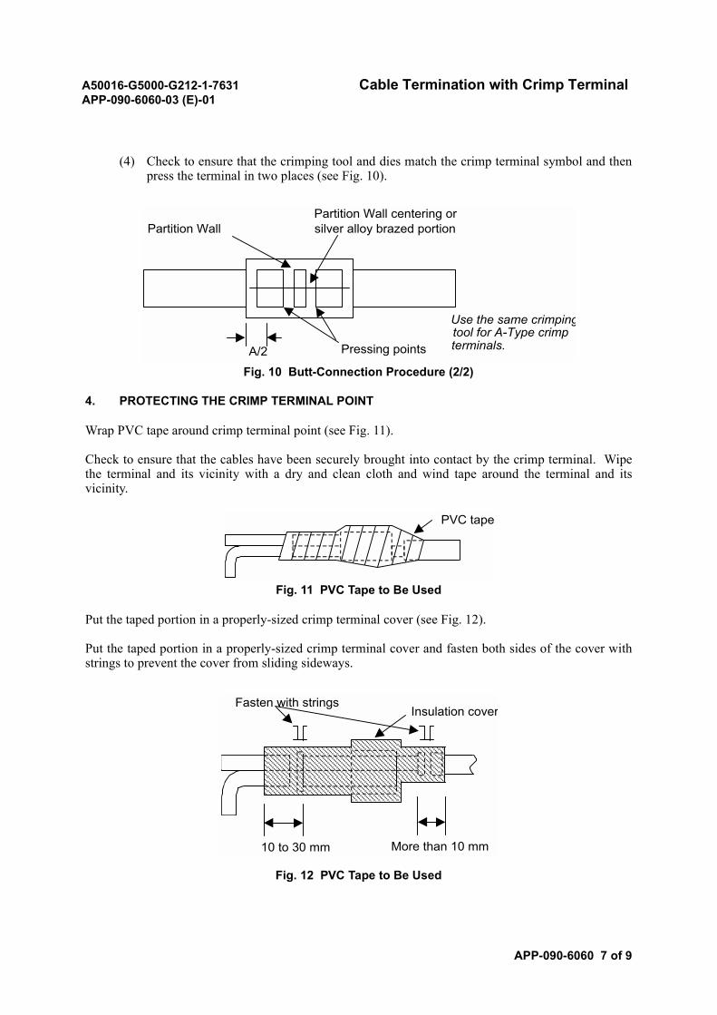
A50016-G5000-G212-1-7631 Cable Termination with Crimp TerminalAPP-090-6060-03 (E)-01
APP-090-6060 7 of 9
(4) Check to ensure that the crimping tool and dies match the crimp terminal symbol and thenpress the terminal in two places (see Fig. 10).
Fig. 10 Butt-Connection Procedure (2/2)
4. PROTECTING THE CRIMP TERMINAL POINT
Wrap PVC tape around crimp terminal point (see Fig. 11).
Check to ensure that the cables have been securely brought into contact by the crimp terminal. Wipethe terminal and its vicinity with a dry and clean cloth and wind tape around the terminal and itsvicinity.
Fig. 11 PVC Tape to Be Used
Put the taped portion in a properly-sized crimp terminal cover (see Fig. 12).
Put the taped portion in a properly-sized crimp terminal cover and fasten both sides of the cover withstrings to prevent the cover from sliding sideways.
Fig. 12 PVC Tape to Be Used
Partition Wall centering orPartition Wall silver alloy brazed portion
Use the same crimpingtool for A-Type crimp
Pressing points terminals.A/2
PVC tape
Insulation coverFasten with strings
10 to 30 mm More than 10 mm
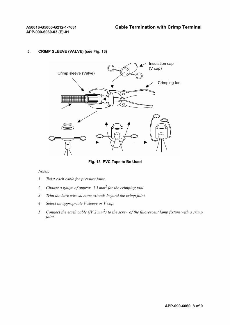
A50016-G5000-G212-1-7631 Cable Termination with Crimp TerminalAPP-090-6060-03 (E)-01
APP-090-6060 8 of 9
5. CRIMP SLEEVE (VALVE) (see Fig. 13)
Fig. 13 PVC Tape to Be Used
Notes:
1 Twist each cable for pressure joint.
2 Choose a gauge of approx. 5.5 mm2 for the crimping tool.
3 Trim the bare wire so none extends beyond the crimp joint.
4 Select an appropriate V sleeve or V cap.
5 Connect the earth cable (IV 2 mm2) to the screw of the fluorescent lamp fixture with a crimpjoint.
Insulation cap(V cap)
Crimp sleeve (Valve)
Crimping too
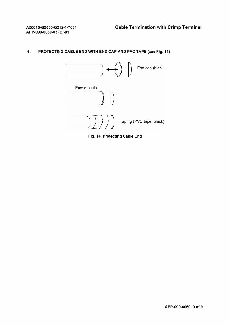
A50016-G5000-G212-1-7631 Cable Termination with Crimp TerminalAPP-090-6060-03 (E)-01
APP-090-6060 9 of 9
6. PROTECTING CABLE END WITH END CAP AND PVC TAPE (see Fig. 14)
Fig. 14 Protecting Cable End
End cap (black)
Power cable
Taping (PVC tape, black)
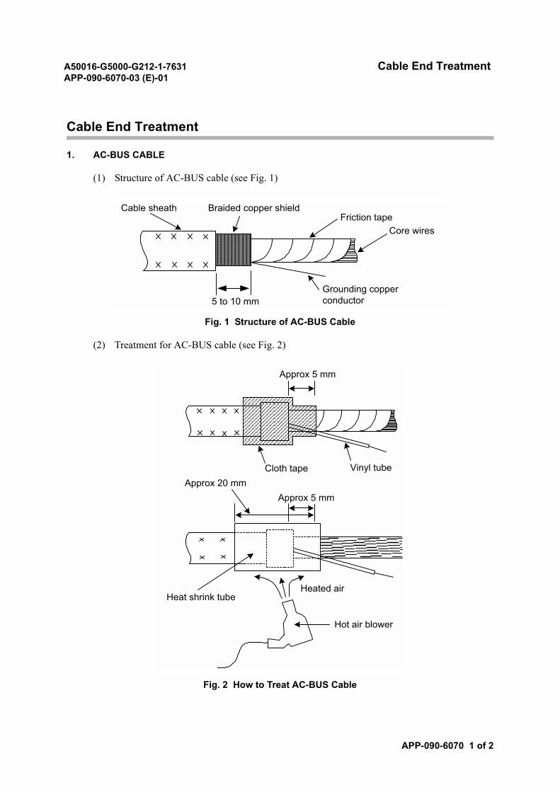
A50016-G5000-G212-1-7631 Cable End TreatmentAPP-090-6070-03 (E)-01
APP-090-6070 1 of 2
Cable End Treatment
1. AC-BUS CABLE
(1) Structure of AC-BUS cable (see Fig. 1)
Fig. 1 Structure of AC-BUS Cable
(2) Treatment for AC-BUS cable (see Fig. 2)
Fig. 2 How to Treat AC-BUS Cable
Cable sheath Braided copper shieldFriction tape
Core wires
5 to 10 mmGrounding copperconductor
Approx 5 mm
Cloth tape Vinyl tube
Approx 5 mmApprox 20 mm
Heat shrink tubeHeated air
Hot air blower
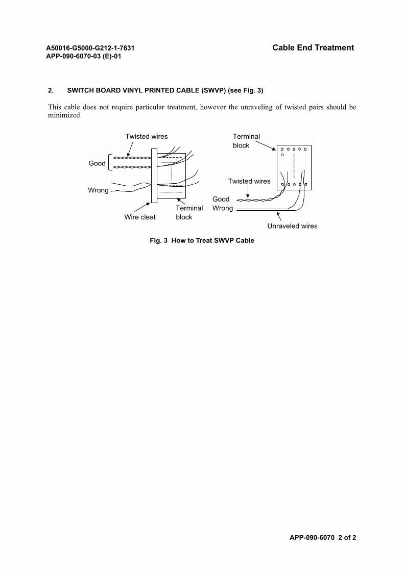
A50016-G5000-G212-1-7631 Cable End TreatmentAPP-090-6070-03 (E)-01
APP-090-6070 2 of 2
2. SWITCH BOARD VINYL PRINTED CABLE (SWVP) (see Fig. 3)
This cable does not require particular treatment, however the unraveling of twisted pairs should beminimized.
Fig. 3 How to Treat SWVP Cable
Twisted wires Terminalblock
Good
Twisted wiresWrong
GoodTerminal Wrong
Wire cleat blockUnraveled wires
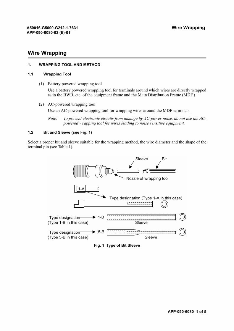
A50016-G5000-G212-1-7631 Wire WrappingAPP-090-6080-02 (E)-01
APP-090-6080 1 of 5
Wire Wrapping
1. WRAPPING TOOL AND METHOD
1.1 Wrapping Tool
(1) Battery powered wrapping toolUse a battery powered wrapping tool for terminals around which wires are directly wrappedas in the BWB, etc. of the equipment frame and the Main Distribution Frame (MDF.)
(2) AC-powered wrapping toolUse an AC-powered wrapping tool for wrapping wires around the MDF terminals.
Note: To prevent electronic circuits from damage by AC-power noise, do not use the AC-powered wrapping tool for wires leading to noise sensitive equipment.
1.2 Bit and Sleeve (see Fig. 1)
Select a proper bit and sleeve suitable for the wrapping method, the wire diameter and the shape of theterminal pin (see Table 1).
Fig. 1 Type of Bit Sleeve
Sleeve Bit
Nozzle of wrapping tool
Type designation (Type 1-A in this case)
Type designation(Type 1-B in this case) Sleeve
Type designation(Type 5-B in this case) Sleeve
1-A
1-B
5-B
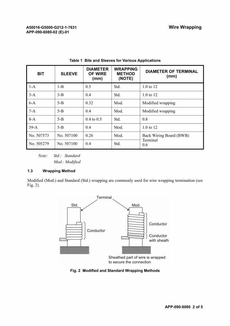
A50016-G5000-G212-1-7631 Wire WrappingAPP-090-6080-02 (E)-01
APP-090-6080 2 of 5
Note: Std.: StandardMod.: Modified
1.3 Wrapping Method
Modified (Mod.) and Standard (Std.) wrapping are commonly used for wire wrapping termination (seeFig. 2).
Fig. 2 Modified and Standard Wrapping Methods
Table 1 Bits and Sleeves for Various Applications
BIT SLEEVEDIAMETEROF WIRE
(mm)
WRAPPINGMETHOD(NOTE)
DIAMETER OF TERMINAL (mm)
1-A 1-B 0.5 Std. 1.0 to 12
3-A 3-B 0.4 Std. 1.0 to 12
6-A 5-B 0.32 Mod. Modified wrapping
7-A 5-B 0.4 Mod. Modified wrapping
8-A 5-B 0.4 to 0.5 Std. 0.8
39-A 5-B 0.4 Mod. 1.0 to 12
No. 507573 No. 507100 0.26 Mod. Back Wiring Board (BWB) Terminal0.6No. 505279 No. 507100 0.4 Std.
Std.
Conductor
Conductor
Conductorwith sheath
Mod.
Terminal
Sheathed part of wire is wrappedto secure the connection
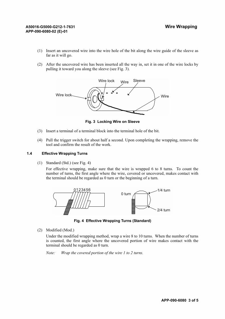
A50016-G5000-G212-1-7631 Wire WrappingAPP-090-6080-02 (E)-01
APP-090-6080 3 of 5
(1) Insert an uncovered wire into the wire hole of the bit along the wire guide of the sleeve asfar as it will go.
(2) After the uncovered wire has been inserted all the way in, set it in one of the wire locks bypulling it toward you along the sleeve (see Fig. 3).
Fig. 3 Locking Wire on Sleeve
(3) Insert a terminal of a terminal block into the terminal hole of the bit.
(4) Pull the trigger switch for about half a second. Upon completing the wrapping, remove thetool and confirm the result of the work.
1.4 Effective Wrapping Turns
(1) Standard (Std.) (see Fig. 4)For effective wrapping, make sure that the wire is wrapped 6 to 8 turns. To count thenumber of turns, the first angle where the wire, covered or uncovered, makes contact withthe terminal should be regarded as 0 turn or the beginning of a turn.
Fig. 4 Effective Wrapping Turns (Standard)
(2) Modified (Mod.)Under the modified wrapping method, wrap a wire 8 to 10 turns. When the number of turnsis counted, the first angle where the uncovered portion of wire makes contact with theterminal should be regarded as 0 turn.
Note: Wrap the covered portion of the wire 1 to 2 turns.
Wire lock
Wire lock Wire
SleeveWire
0 3 60 turn
1/4 turn
2/4 turn
21 45
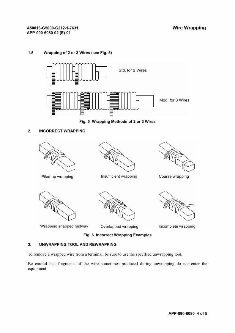
A50016-G5000-G212-1-7631 Wire WrappingAPP-090-6080-02 (E)-01
APP-090-6080 4 of 5
1.5 Wrapping of 2 or 3 Wires (see Fig. 5)
Fig. 5 Wrapping Methods of 2 or 3 Wires
2. INCORRECT WRAPPING
Fig. 6 Incorrect Wrapping Examples
3. UNWRAPPING TOOL AND REWRAPPING
To remove a wrapped wire from a terminal, be sure to use the specified unwrapping tool.
Be careful that fragments of the wire sometimes produced during unwrapping do not enter theequipment.
Std. for 2 Wires
Mod. for 3 Wires
Incomplete wrappingOverlapped wrappingWrapping snapped midway
Piled-up wrapping Insufficient wrapping Coarse wrapping
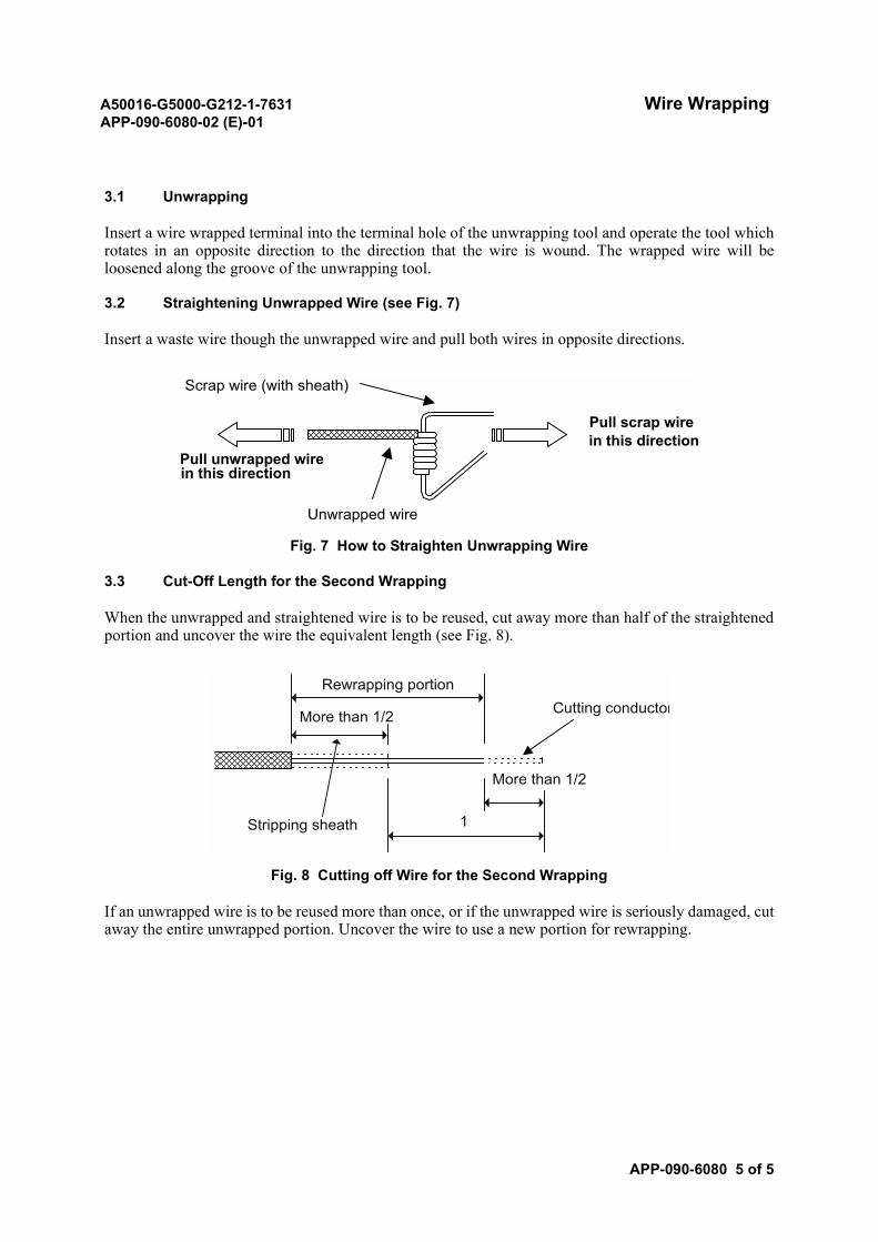
A50016-G5000-G212-1-7631 Wire WrappingAPP-090-6080-02 (E)-01
APP-090-6080 5 of 5
3.1 Unwrapping
Insert a wire wrapped terminal into the terminal hole of the unwrapping tool and operate the tool whichrotates in an opposite direction to the direction that the wire is wound. The wrapped wire will beloosened along the groove of the unwrapping tool.
3.2 Straightening Unwrapped Wire (see Fig. 7)
Insert a waste wire though the unwrapped wire and pull both wires in opposite directions.
Fig. 7 How to Straighten Unwrapping Wire
3.3 Cut-Off Length for the Second Wrapping
When the unwrapped and straightened wire is to be reused, cut away more than half of the straightenedportion and uncover the wire the equivalent length (see Fig. 8).
Fig. 8 Cutting off Wire for the Second Wrapping
If an unwrapped wire is to be reused more than once, or if the unwrapped wire is seriously damaged, cutaway the entire unwrapped portion. Uncover the wire to use a new portion for rewrapping.
Scrap wire (with sheath)
Pull scrap wirein this direction
Pull unwrapped wirein this direction
Unwrapped wire
Stripping sheath 1
Cutting conductorMore than 1/2
More than 1/2
Rewrapping portion
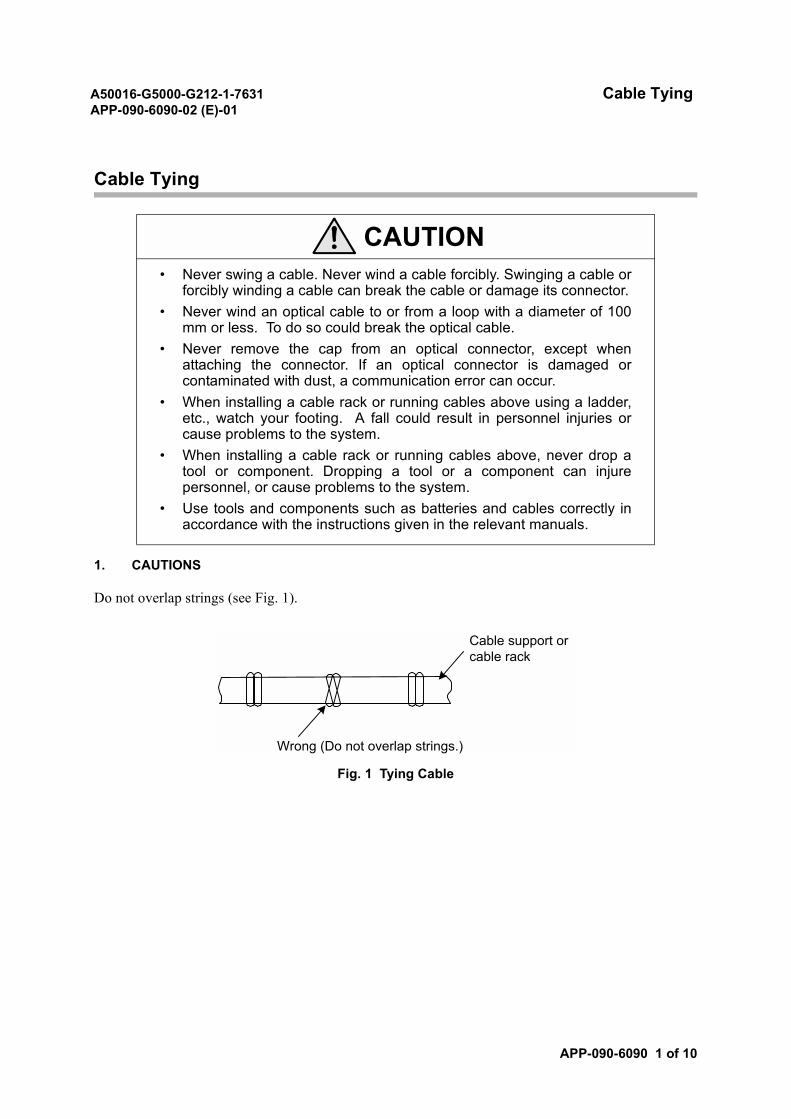
A50016-G5000-G212-1-7631 Cable TyingAPP-090-6090-02 (E)-01
APP-090-6090 1 of 10
Cable Tying
1. CAUTIONS
Do not overlap strings (see Fig. 1).
Fig. 1 Tying Cable
CAUTION• Never swing a cable. Never wind a cable forcibly. Swinging a cable or
forcibly winding a cable can break the cable or damage its connector.• Never wind an optical cable to or from a loop with a diameter of 100
mm or less. To do so could break the optical cable.• Never remove the cap from an optical connector, except when
attaching the connector. If an optical connector is damaged orcontaminated with dust, a communication error can occur.
• When installing a cable rack or running cables above using a ladder,etc., watch your footing. A fall could result in personnel injuries orcause problems to the system.
• When installing a cable rack or running cables above, never drop atool or component. Dropping a tool or a component can injurepersonnel, or cause problems to the system.
• Use tools and components such as batteries and cables correctly inaccordance with the instructions given in the relevant manuals.
Cable support orcable rack
Wrong (Do not overlap strings.)
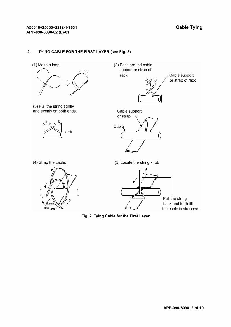
A50016-G5000-G212-1-7631 Cable TyingAPP-090-6090-02 (E)-01
APP-090-6090 2 of 10
2. TYING CABLE FOR THE FIRST LAYER (see Fig. 2)
Fig. 2 Tying Cable for the First Layer
(1) Make a loop. (2) Pass around cablesupport or strap ofrack. Cable support
or strap of rack
(3) Pull the string tightlyand evenly on both ends. Cable support
or strapa b
Cablea=b
(4) Strap the cable. (5) Locate the string knot.
Pull the stringback and forth tillthe cable is strapped.
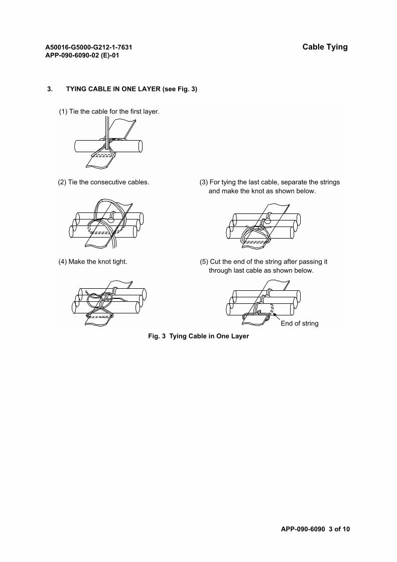
A50016-G5000-G212-1-7631 Cable TyingAPP-090-6090-02 (E)-01
APP-090-6090 3 of 10
3. TYING CABLE IN ONE LAYER (see Fig. 3)
Fig. 3 Tying Cable in One Layer
(1) Tie the cable for the first layer.
(2) Tie the consecutive cables. (3) For tying the last cable, separate the stringsand make the knot as shown below.
(4) Make the knot tight. (5) Cut the end of the string after passing itthrough last cable as shown below.
End of string
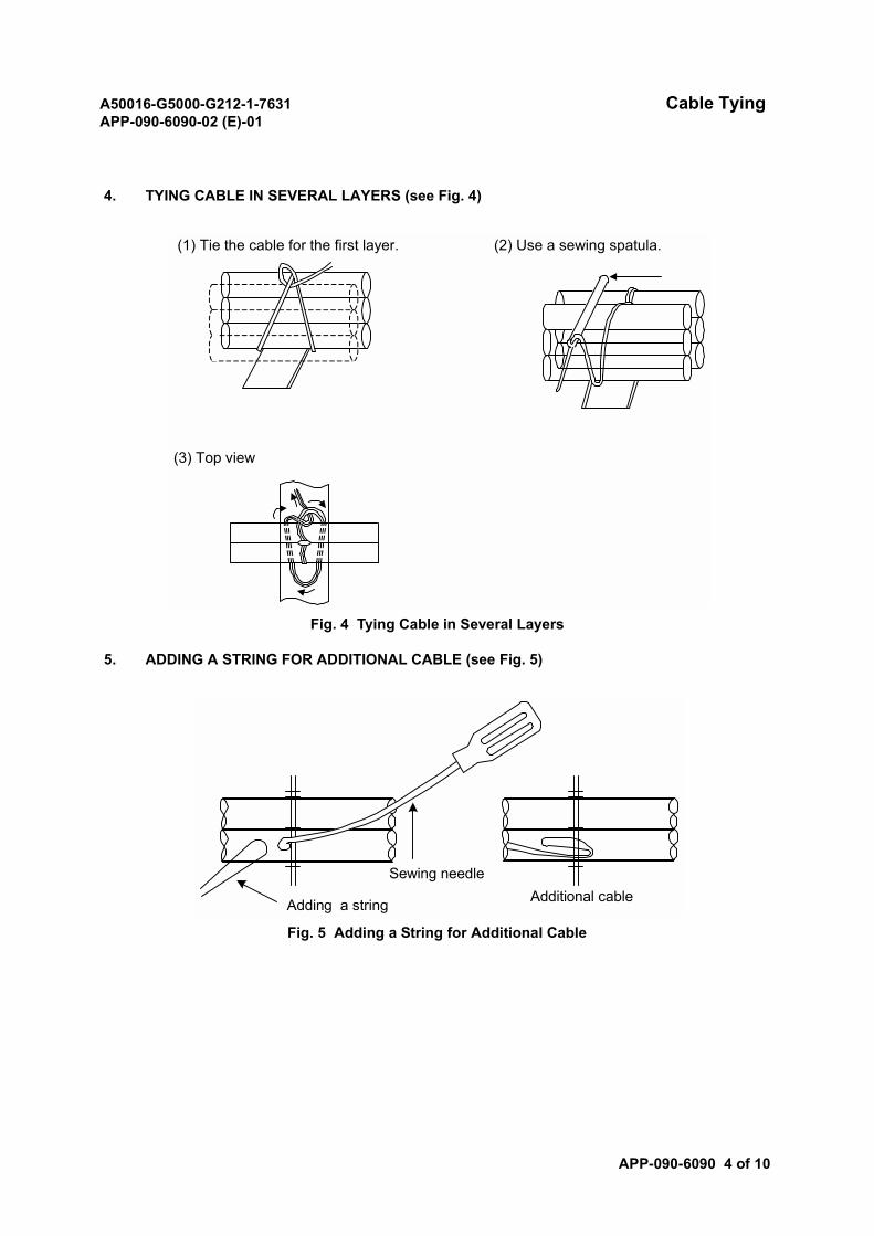
A50016-G5000-G212-1-7631 Cable TyingAPP-090-6090-02 (E)-01
APP-090-6090 4 of 10
4. TYING CABLE IN SEVERAL LAYERS (see Fig. 4)
Fig. 4 Tying Cable in Several Layers
5. ADDING A STRING FOR ADDITIONAL CABLE (see Fig. 5)
Fig. 5 Adding a String for Additional Cable
(1) Tie the cable for the first layer. (2) Use a sewing spatula.
(3) Top view
Additional cableSewing needle
Adding a string
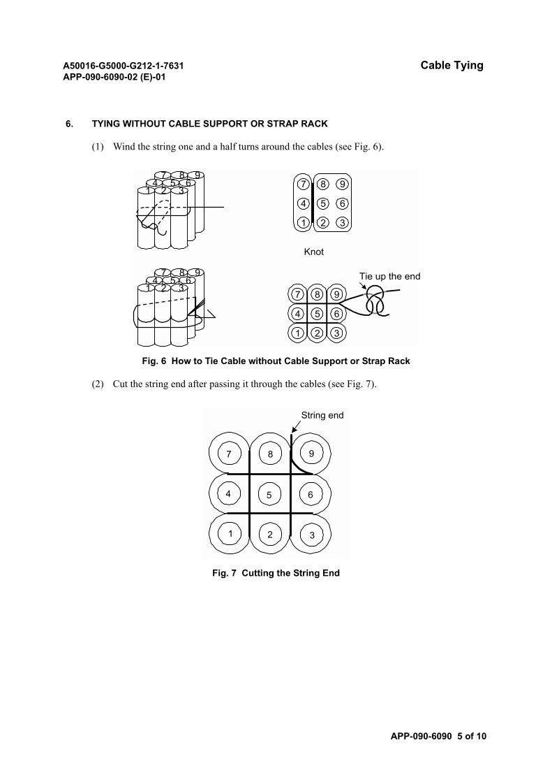
A50016-G5000-G212-1-7631 Cable TyingAPP-090-6090-02 (E)-01
APP-090-6090 5 of 10
6. TYING WITHOUT CABLE SUPPORT OR STRAP RACK
(1) Wind the string one and a half turns around the cables (see Fig. 6).
Fig. 6 How to Tie Cable without Cable Support or Strap Rack
(2) Cut the string end after passing it through the cables (see Fig. 7).
Fig. 7 Cutting the String End
Knot
Tie up the end
8 97
5 64
2 31
8 97
5 64
2 31
7 8 94 5 6
1 2 3
7 8 94 5 6
1 2 3
1 2 3
4 5 6
7 8 9
String end
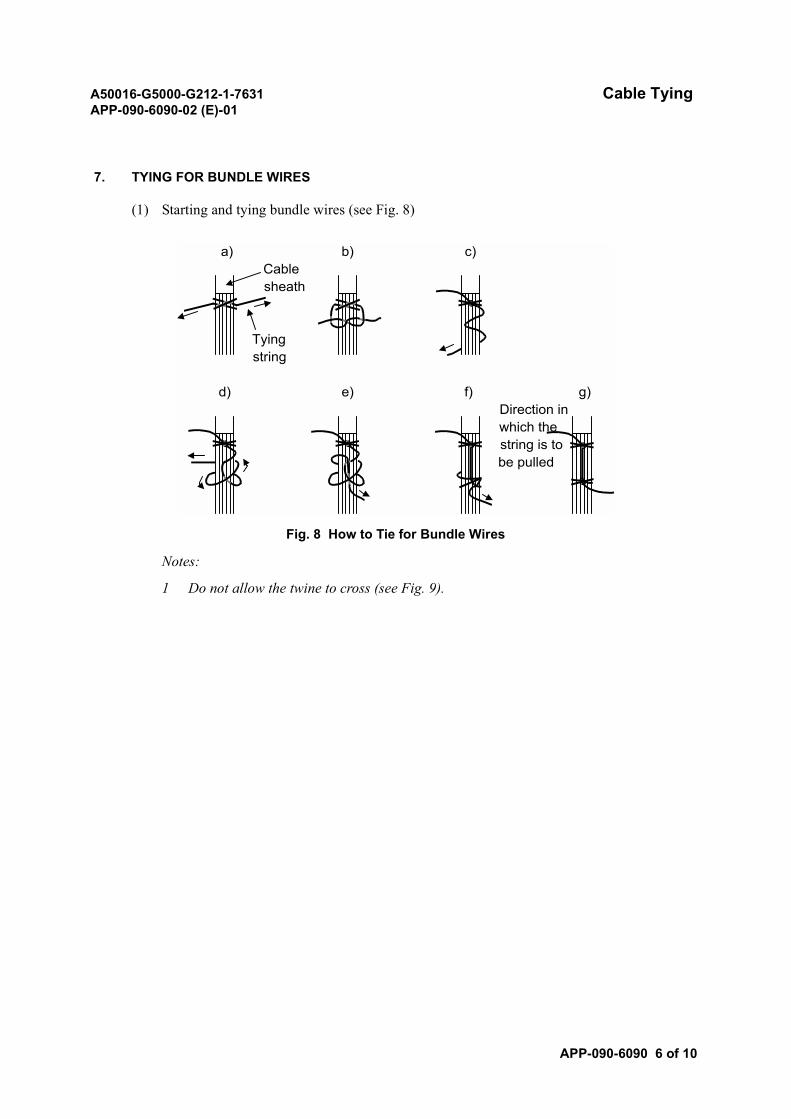
A50016-G5000-G212-1-7631 Cable TyingAPP-090-6090-02 (E)-01
APP-090-6090 6 of 10
7. TYING FOR BUNDLE WIRES
(1) Starting and tying bundle wires (see Fig. 8)
Fig. 8 How to Tie for Bundle Wires
Notes:
1 Do not allow the twine to cross (see Fig. 9).
a) b) c)Cablesheath
Tyingstring
d) e) f) g)Direction inwhich thestring is tobe pulled
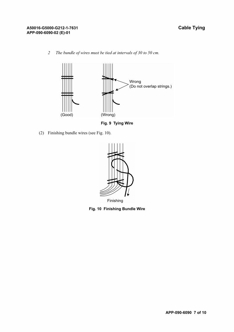
A50016-G5000-G212-1-7631 Cable TyingAPP-090-6090-02 (E)-01
APP-090-6090 7 of 10
2 The bundle of wires must be tied at intervals of 30 to 50 cm.
Fig. 9 Tying Wire
(2) Finishing bundle wires (see Fig. 10).
Fig. 10 Finishing Bundle Wire
Wrong(Do not overlap strings.)
(Wrong)(Good)
Finishing
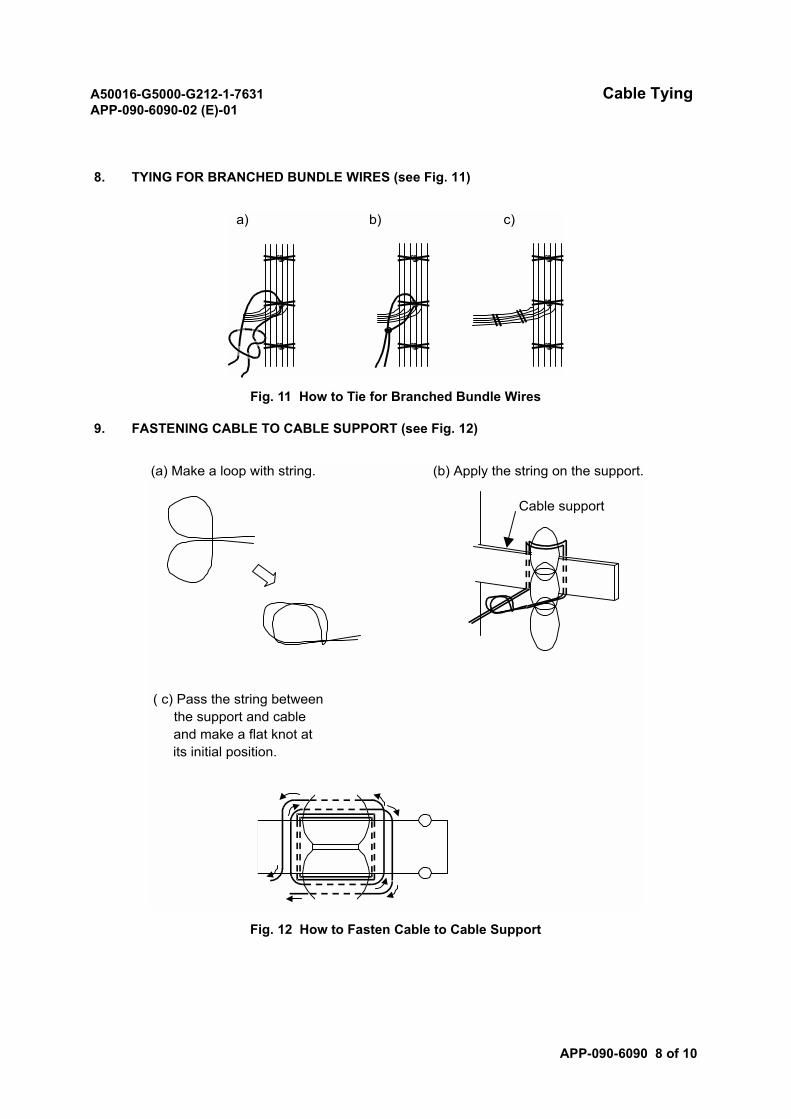
A50016-G5000-G212-1-7631 Cable TyingAPP-090-6090-02 (E)-01
APP-090-6090 8 of 10
8. TYING FOR BRANCHED BUNDLE WIRES (see Fig. 11)
Fig. 11 How to Tie for Branched Bundle Wires
9. FASTENING CABLE TO CABLE SUPPORT (see Fig. 12)
Fig. 12 How to Fasten Cable to Cable Support
a) b) c)
(a) Make a loop with string. (b) Apply the string on the support.
Cable support
( c) Pass the string betweenthe support and cableand make a flat knot atits initial position.
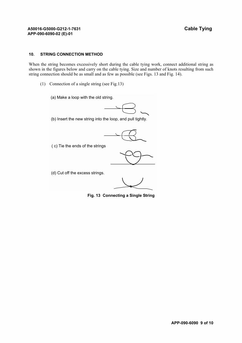
A50016-G5000-G212-1-7631 Cable TyingAPP-090-6090-02 (E)-01
APP-090-6090 9 of 10
10. STRING CONNECTION METHOD
When the string becomes excessively short during the cable tying work, connect additional string asshown in the figures below and carry on the cable tying. Size and number of knots resulting from suchstring connection should be as small and as few as possible (see Figs. 13 and Fig. 14).
(1) Connection of a single string (see Fig.13)
Fig. 13 Connecting a Single String
(a) Make a loop with the old string.
(b) Insert the new string into the loop, and pull tightly.
( c) Tie the ends of the strings
(d) Cut off the excess strings.
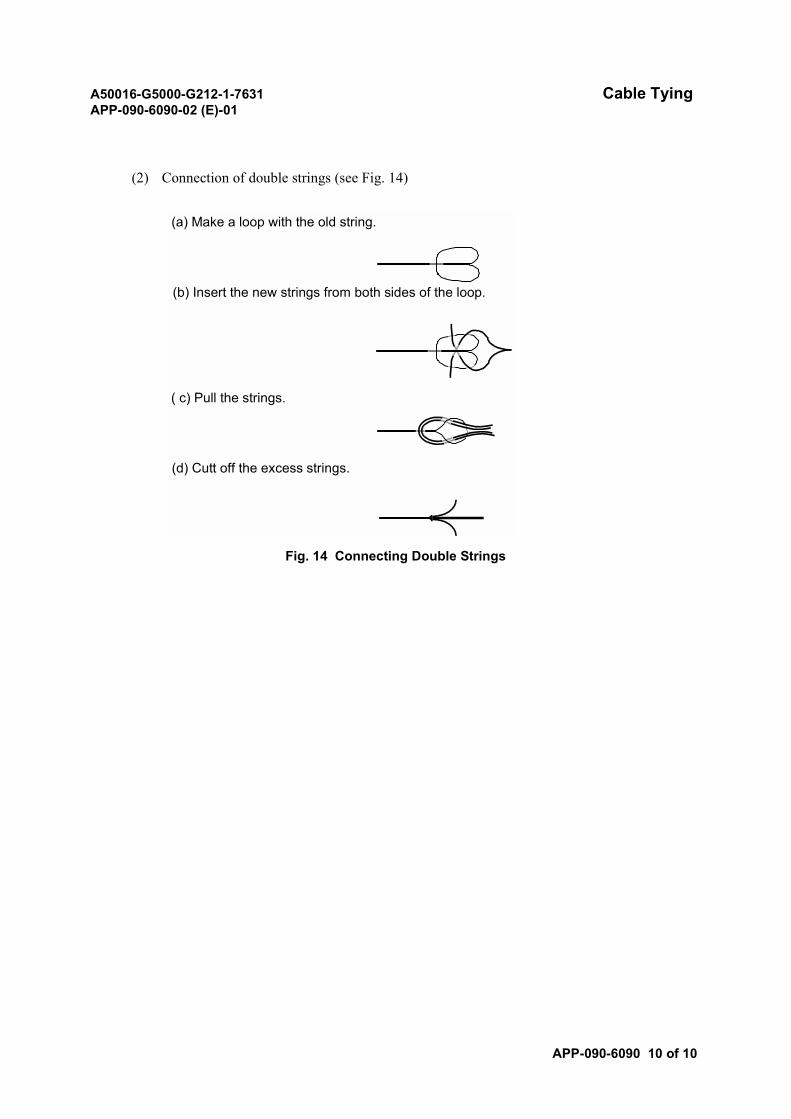
A50016-G5000-G212-1-7631 Cable TyingAPP-090-6090-02 (E)-01
APP-090-6090 10 of 10
(2) Connection of double strings (see Fig. 14)
Fig. 14 Connecting Double Strings
(a) Make a loop with the old string.
(b) Insert the new strings from both sides of the loop.
( c) Pull the strings.
(d) Cutt off the excess strings.
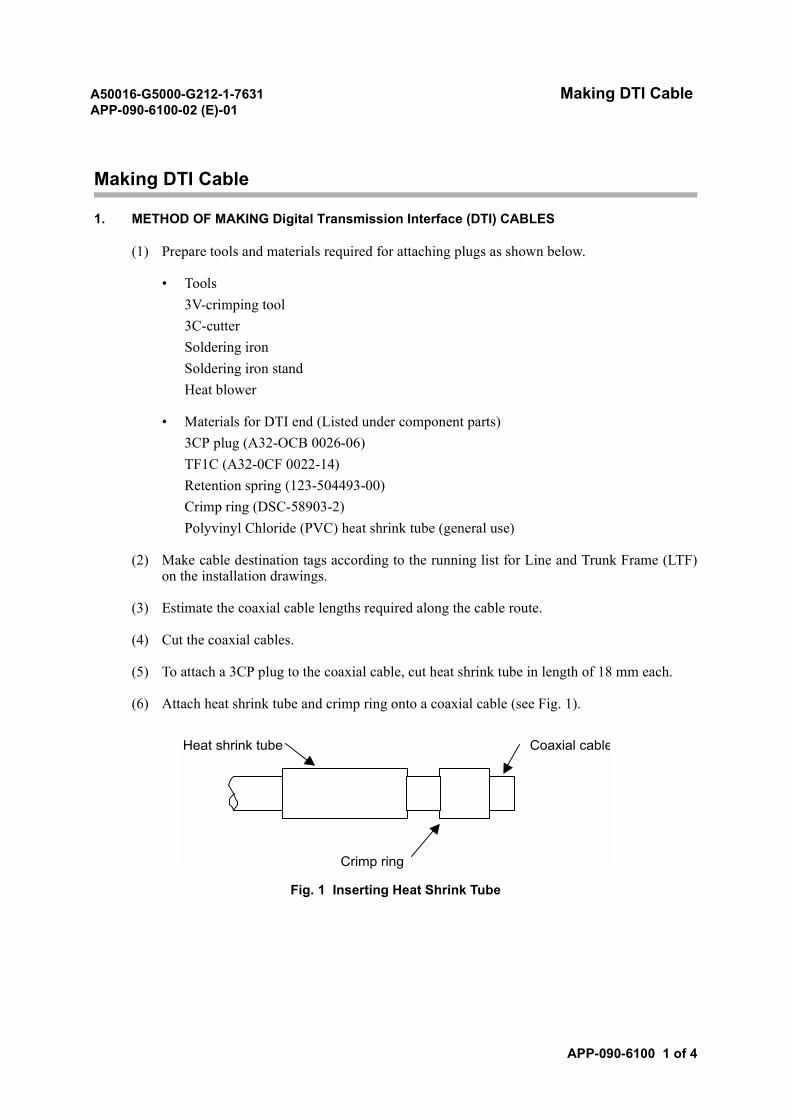
A50016-G5000-G212-1-7631 Making DTI CableAPP-090-6100-02 (E)-01
APP-090-6100 1 of 4
Making DTI Cable
1. METHOD OF MAKING Digital Transmission Interface (DTI) CABLES
(1) Prepare tools and materials required for attaching plugs as shown below.
• Tools3V-crimping tool3C-cutterSoldering ironSoldering iron standHeat blower
• Materials for DTI end (Listed under component parts)3CP plug (A32-OCB 0026-06)TF1C (A32-0CF 0022-14)Retention spring (123-504493-00)Crimp ring (DSC-58903-2)Polyvinyl Chloride (PVC) heat shrink tube (general use)
(2) Make cable destination tags according to the running list for Line and Trunk Frame (LTF)on the installation drawings.
(3) Estimate the coaxial cable lengths required along the cable route.
(4) Cut the coaxial cables.
(5) To attach a 3CP plug to the coaxial cable, cut heat shrink tube in length of 18 mm each.
(6) Attach heat shrink tube and crimp ring onto a coaxial cable (see Fig. 1).
Fig. 1 Inserting Heat Shrink Tube
Heat shrink tube Coaxial cable
Crimp ring
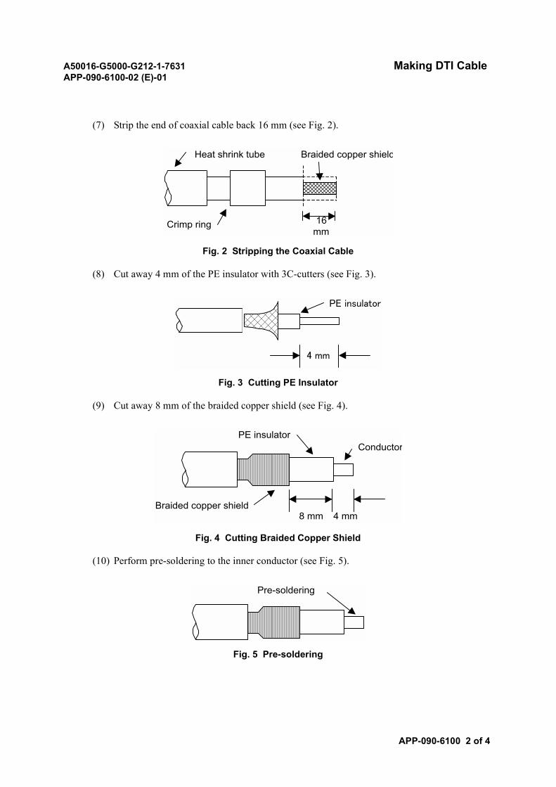
A50016-G5000-G212-1-7631 Making DTI CableAPP-090-6100-02 (E)-01
APP-090-6100 2 of 4
(7) Strip the end of coaxial cable back 16 mm (see Fig. 2).
Fig. 2 Stripping the Coaxial Cable
(8) Cut away 4 mm of the PE insulator with 3C-cutters (see Fig. 3).
Fig. 3 Cutting PE Insulator
(9) Cut away 8 mm of the braided copper shield (see Fig. 4).
Fig. 4 Cutting Braided Copper Shield
(10) Perform pre-soldering to the inner conductor (see Fig. 5).
Fig. 5 Pre-soldering
Heat shrink tube Braided copper shield
Crimp ring 16mm
PE insulator
4 mm
PE insulatorConductor
Braided copper shield4 mm8 mm
Pre-soldering
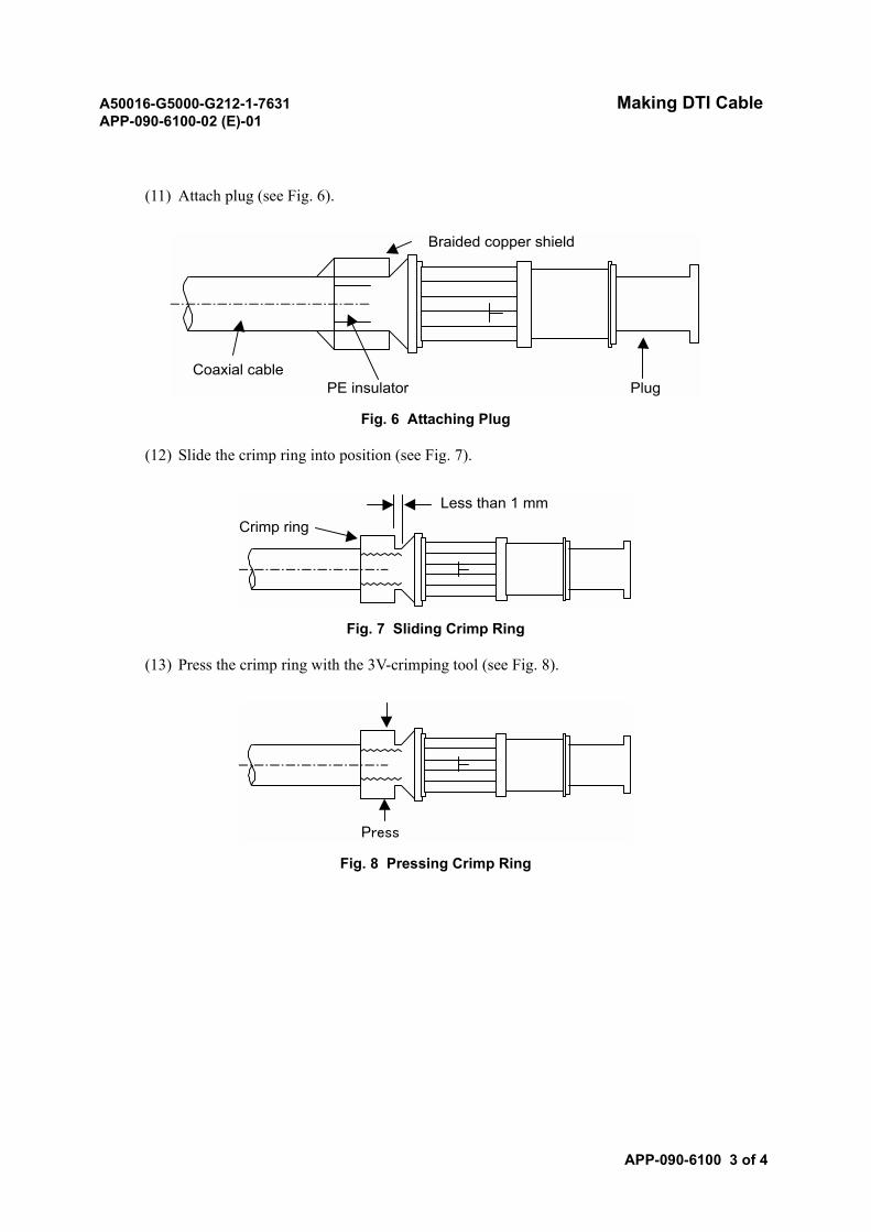
A50016-G5000-G212-1-7631 Making DTI CableAPP-090-6100-02 (E)-01
APP-090-6100 3 of 4
(11) Attach plug (see Fig. 6).
Fig. 6 Attaching Plug
(12) Slide the crimp ring into position (see Fig. 7).
Fig. 7 Sliding Crimp Ring
(13) Press the crimp ring with the 3V-crimping tool (see Fig. 8).
Fig. 8 Pressing Crimp Ring
Braided copper shield
Coaxial cablePE insulator Plug
Crimp ringLess than 1 mm
Press
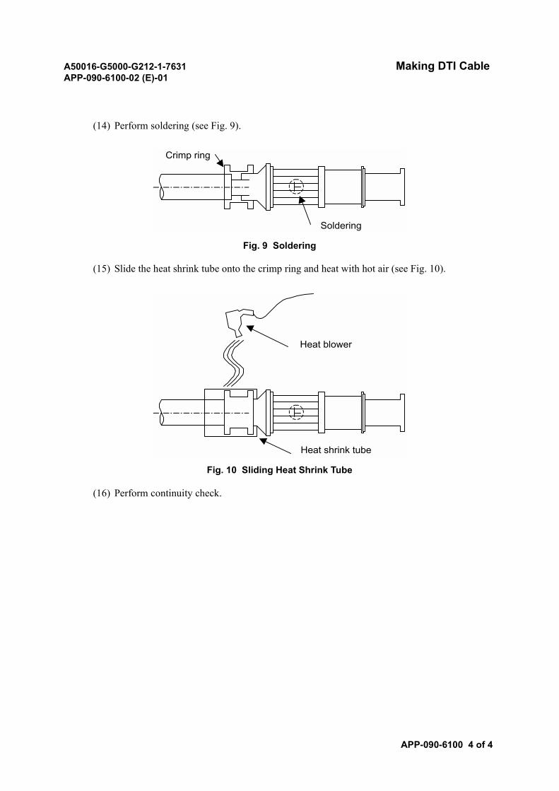
A50016-G5000-G212-1-7631 Making DTI CableAPP-090-6100-02 (E)-01
APP-090-6100 4 of 4
(14) Perform soldering (see Fig. 9).
Fig. 9 Soldering
(15) Slide the heat shrink tube onto the crimp ring and heat with hot air (see Fig. 10).
Fig. 10 Sliding Heat Shrink Tube
(16) Perform continuity check.
Crimp ring
Soldering
Heat blower
Heat shrink tube

A50016-G5000-G212-1-7631ND-57268-706 (E)-01
SECTION 8INSTALLATION PARTS
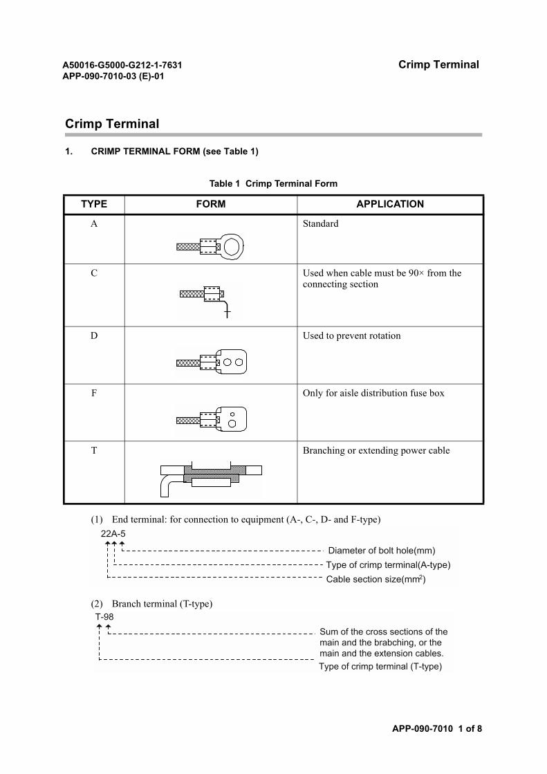
A50016-G5000-G212-1-7631 Crimp TerminalAPP-090-7010-03 (E)-01
APP-090-7010 1 of 8
Crimp Terminal
1. CRIMP TERMINAL FORM (see Table 1)
(1) End terminal: for connection to equipment (A-, C-, D- and F-type)
(2) Branch terminal (T-type)
Table 1 Crimp Terminal Form
TYPE FORM APPLICATION
A Standard
C Used when cable must be 90× from the connecting section
D Used to prevent rotation
F Only for aisle distribution fuse box
T Branching or extending power cable
22A-5
Diameter of bolt hole(mm)Type of crimp terminal(A-type)Cable section size(mm2)
T-98Sum of the cross sections of themain and the brabching, or themain and the extension cables.Type of crimp terminal (T-type)
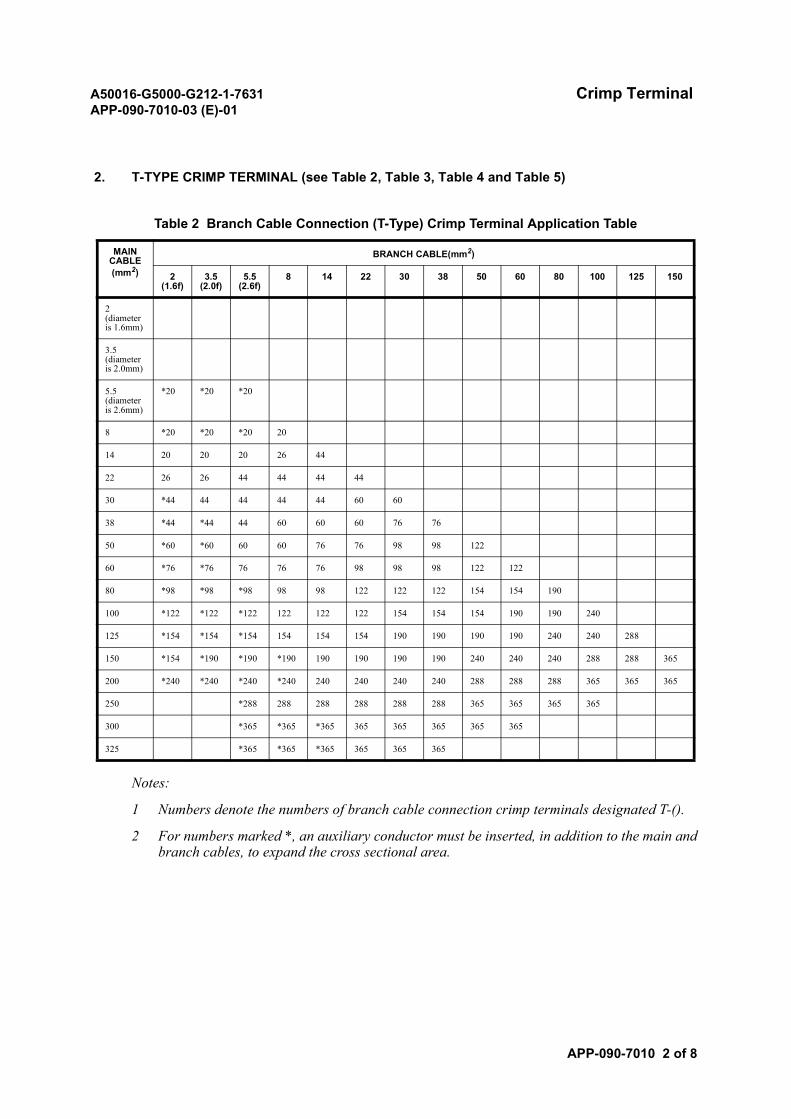
A50016-G5000-G212-1-7631 Crimp TerminalAPP-090-7010-03 (E)-01
APP-090-7010 2 of 8
2. T-TYPE CRIMP TERMINAL (see Table 2, Table 3, Table 4 and Table 5)
Notes:
1 Numbers denote the numbers of branch cable connection crimp terminals designated T-().
2 For numbers marked *, an auxiliary conductor must be inserted, in addition to the main andbranch cables, to expand the cross sectional area.
Table 2 Branch Cable Connection (T-Type) Crimp Terminal Application Table
MAIN CABLE (mm2)
BRANCH CABLE(mm2)
2(1.6f)
3.5(2.0f)
5.5(2.6f)
8 14 22 30 38 50 60 80 100 125 150
2 (diameter is 1.6mm)
3.5 (diameter is 2.0mm)
5.5 (diameter is 2.6mm)
*20 *20 *20
8 *20 *20 *20 20
14 20 20 20 26 44
22 26 26 44 44 44 44
30 *44 44 44 44 44 60 60
38 *44 *44 44 60 60 60 76 76
50 *60 *60 60 60 76 76 98 98 122
60 *76 *76 76 76 76 98 98 98 122 122
80 *98 *98 *98 98 98 122 122 122 154 154 190
100 *122 *122 *122 122 122 122 154 154 154 190 190 240
125 *154 *154 *154 154 154 154 190 190 190 190 240 240 288
150 *154 *190 *190 *190 190 190 190 190 240 240 240 288 288 365
200 *240 *240 *240 *240 240 240 240 240 288 288 288 365 365 365
250 *288 288 288 288 288 288 365 365 365 365
300 *365 *365 *365 365 365 365 365 365
325 *365 *365 *365 365 365 365
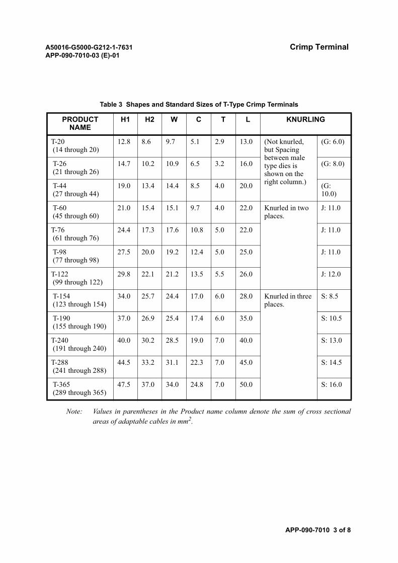
A50016-G5000-G212-1-7631 Crimp TerminalAPP-090-7010-03 (E)-01
APP-090-7010 3 of 8
Note: Values in parentheses in the Product name column denote the sum of cross sectionalareas of adaptable cables in mm2.
Table 3 Shapes and Standard Sizes of T-Type Crimp Terminals
PRODUCT NAME
H1 H2 W C T L KNURLING
T-20 (14 through 20)
12.8 8.6 9.7 5.1 2.9 13.0 (Not knurled, but Spacing between male type dies is shown on the right column.)
(G: 6.0)
T-26 (21 through 26)
14.7 10.2 10.9 6.5 3.2 16.0 (G: 8.0)
T-44 (27 through 44)
19.0 13.4 14.4 8.5 4.0 20.0 (G: 10.0)
T-60 (45 through 60)
21.0 15.4 15.1 9.7 4.0 22.0 Knurled in two places.
J: 11.0
T-76 (61 through 76)
24.4 17.3 17.6 10.8 5.0 22.0 J: 11.0
T-98 (77 through 98)
27.5 20.0 19.2 12.4 5.0 25.0 J: 11.0
T-122 (99 through 122)
29.8 22.1 21.2 13.5 5.5 26.0 J: 12.0
T-154 (123 through 154)
34.0 25.7 24.4 17.0 6.0 28.0 Knurled in three places.
S: 8.5
T-190 (155 through 190)
37.0 26.9 25.4 17.4 6.0 35.0 S: 10.5
T-240 (191 through 240)
40.0 30.2 28.5 19.0 7.0 40.0 S: 13.0
T-288 (241 through 288)
44.5 33.2 31.1 22.3 7.0 45.0 S: 14.5
T-365 (289 through 365)
47.5 37.0 34.0 24.8 7.0 50.0 S: 16.0
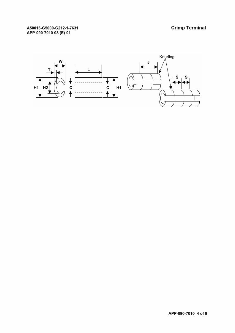
A50016-G5000-G212-1-7631 Crimp TerminalAPP-090-7010-03 (E)-01
APP-090-7010 4 of 8
Knurling
S S
J
H1C
L
CH1 H2
W
T
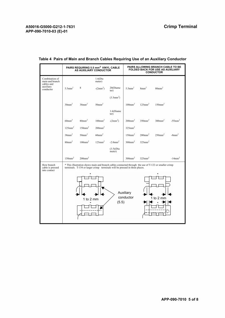
A50016-G5000-G212-1-7631 Crimp TerminalAPP-090-7010-03 (E)-01
APP-090-7010 5 of 8
Table 4 Pairs of Main and Branch Cables Requiring Use of an Auxiliary Conductor
PAIRS REQUIRING 5.5 mm2 VINYL CABLE AS AUXILIARY CONDUCTOR
PAIRS ALLOWING BRANCH CABLE TO BE FOLDED BACK FOR USE AS AUXILIARY
CONDUCTOR
Combination of main and branch cables and auxiliary conductor
1.6(Diameter)
5.5mm2 8 -(2mm2) 20(Diameter)
5.5mm2 8mm2 80mm2
(3.5mm2)
30mm2 38mm2 50mm2 100mm2 125mm2 150mm2
1.6(Diameter)
60mm2 80mm2 100mm2 -(2mm2) 200mm2 350mm2 300mm2 -55mm2
125mm2 150mm2 200mm2 325mm2
38mm2 50mm2 60mm2 150mm2 200mm2 250mm2 -8mm2
80mm2 100mm2 125mm2 -2.0mm2 300mm2 325mm2
(3.5)(Diameter)
150mm2 200mm2 300mm2 325mm2 -14mm2
How branch cable is pressed into contact
* This illustration shows main and branch cables connected through the use of T-122 or smaller crimp terminals. T-154 or larger crimp terminals will be pressed in three places.
*
Auxiliaryconductor
(5.5)
*
1 to 2 mm 1 to 2 mm* *
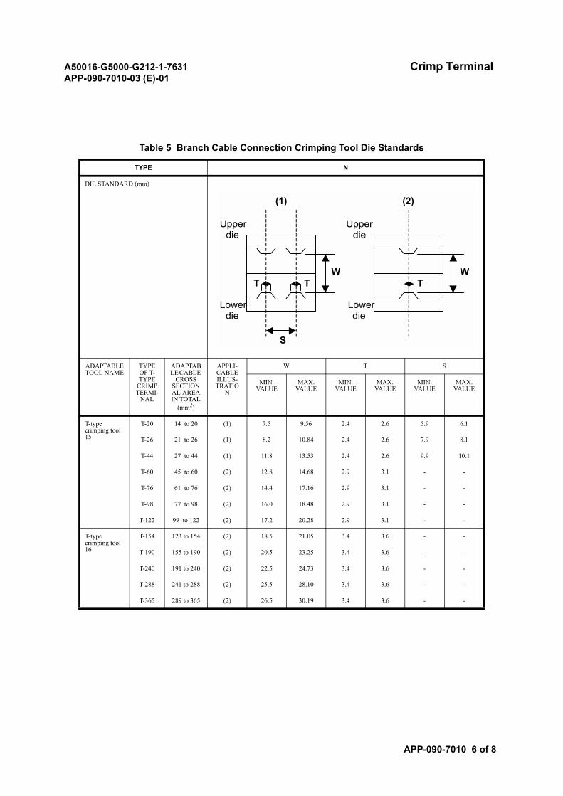
A50016-G5000-G212-1-7631 Crimp TerminalAPP-090-7010-03 (E)-01
APP-090-7010 6 of 8
Table 5 Branch Cable Connection Crimping Tool Die Standards
TYPE N
DIE STANDARD (mm)
ADAPTABLE TOOL NAME
TYPE OF T-TYPE
CRIMP TERMI-
NAL
ADAPTABLE CABLE
CROSS SECTIONAL AREA IN TOTAL
(mm2)
APPLI-CABLE ILLUS-TRATIO
N
W T S
MIN.VALUE
MAX.VALUE
MIN.VALUE
MAX.VALUE
MIN.VALUE
MAX.VALUE
T-type crimping tool 15
T-20 14 to 20 (1) 7.5 9.56 2.4 2.6 5.9 6.1
T-26 21 to 26 (1) 8.2 10.84 2.4 2.6 7.9 8.1
T-44 27 to 44 (1) 11.8 13.53 2.4 2.6 9.9 10.1
T-60 45 to 60 (2) 12.8 14.68 2.9 3.1 - -
T-76 61 to 76 (2) 14.4 17.16 2.9 3.1 - -
T-98 77 to 98 (2) 16.0 18.48 2.9 3.1 - -
T-122 99 to 122 (2) 17.2 20.28 2.9 3.1 - -
T-type crimping tool 16
T-154 123 to 154 (2) 18.5 21.05 3.4 3.6 - -
T-190 155 to 190 (2) 20.5 23.25 3.4 3.6 - -
T-240 191 to 240 (2) 22.5 24.73 3.4 3.6 - -
T-288 241 to 288 (2) 25.5 28.10 3.4 3.6 - -
T-365 289 to 365 (2) 26.5 30.19 3.4 3.6 - -
T TW
S
(1)
W
(2)
T
Upperdie
Upperdie
Lowerdie
Lowerdie
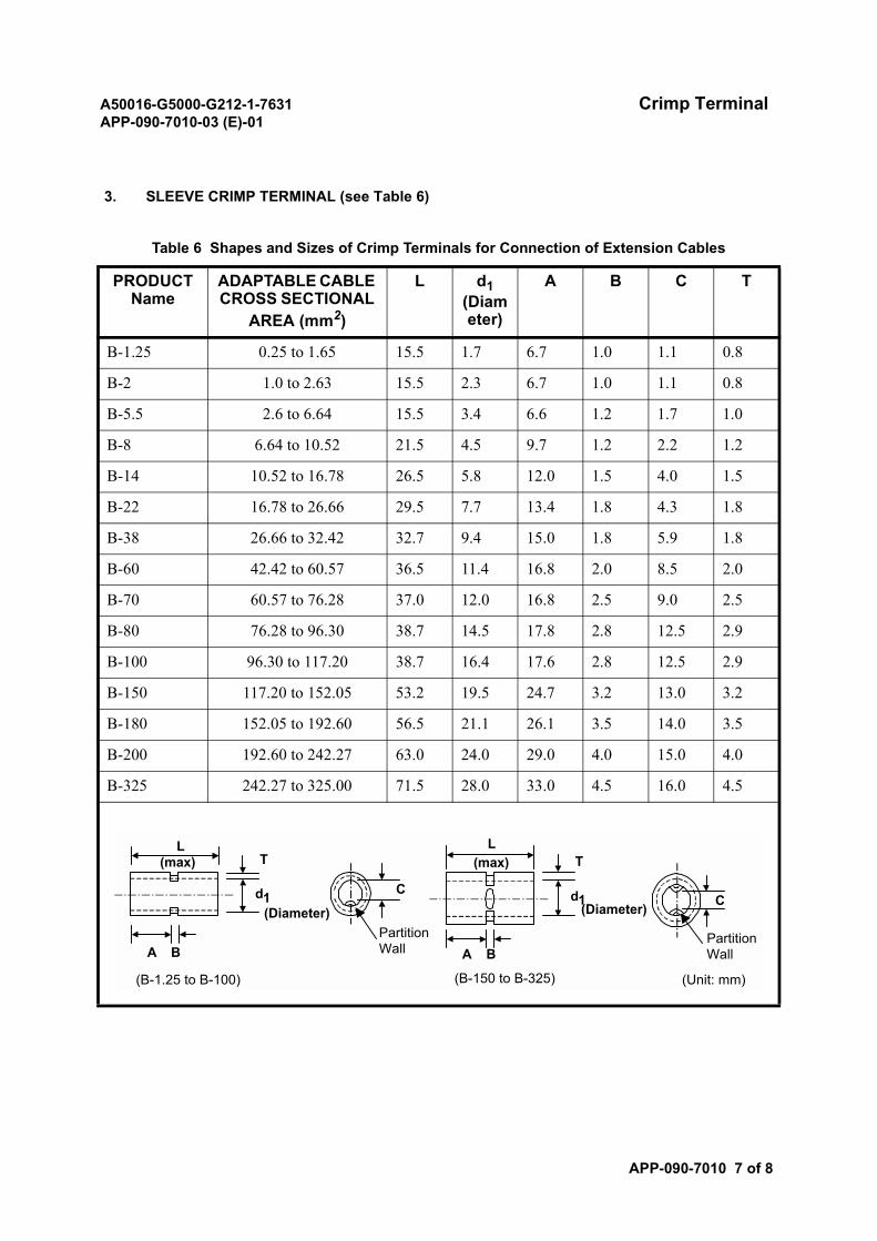
A50016-G5000-G212-1-7631 Crimp TerminalAPP-090-7010-03 (E)-01
APP-090-7010 7 of 8
3. SLEEVE CRIMP TERMINAL (see Table 6)
Table 6 Shapes and Sizes of Crimp Terminals for Connection of Extension Cables
PRODUCT Name
ADAPTABLE CABLE CROSS SECTIONAL
AREA (mm2)
L d1(Diameter)
A B C T
B-1.25 0.25 to 1.65 15.5 1.7 6.7 1.0 1.1 0.8
B-2 1.0 to 2.63 15.5 2.3 6.7 1.0 1.1 0.8
B-5.5 2.6 to 6.64 15.5 3.4 6.6 1.2 1.7 1.0
B-8 6.64 to 10.52 21.5 4.5 9.7 1.2 2.2 1.2
B-14 10.52 to 16.78 26.5 5.8 12.0 1.5 4.0 1.5
B-22 16.78 to 26.66 29.5 7.7 13.4 1.8 4.3 1.8
B-38 26.66 to 32.42 32.7 9.4 15.0 1.8 5.9 1.8
B-60 42.42 to 60.57 36.5 11.4 16.8 2.0 8.5 2.0
B-70 60.57 to 76.28 37.0 12.0 16.8 2.5 9.0 2.5
B-80 76.28 to 96.30 38.7 14.5 17.8 2.8 12.5 2.9
B-100 96.30 to 117.20 38.7 16.4 17.6 2.8 12.5 2.9
B-150 117.20 to 152.05 53.2 19.5 24.7 3.2 13.0 3.2
B-180 152.05 to 192.60 56.5 21.1 26.1 3.5 14.0 3.5
B-200 192.60 to 242.27 63.0 24.0 29.0 4.0 15.0 4.0
B-325 242.27 to 325.00 71.5 28.0 33.0 4.5 16.0 4.5
A B
d1
TL
(max)
A B
d1
TL
(max)
CC
PartitionWall
(B-1.25 to B-100) (B-150 to B-325) (Unit: mm)
(Diameter) (Diameter)
PartitionWall
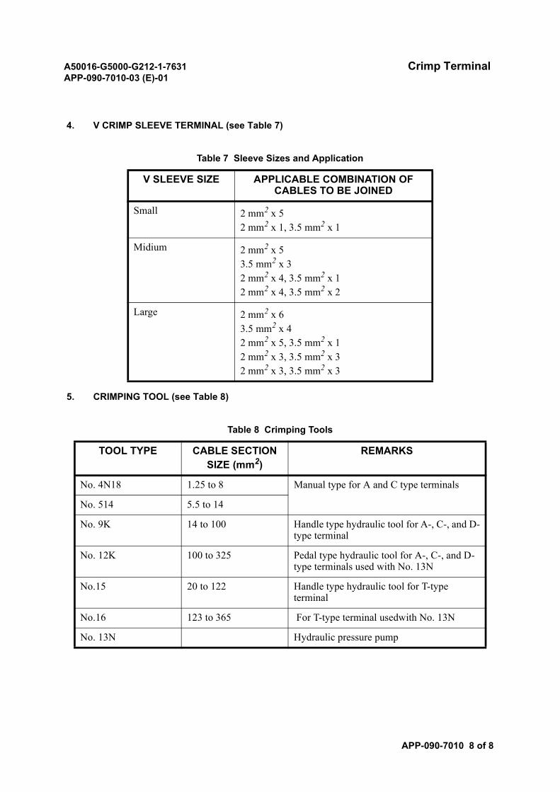
A50016-G5000-G212-1-7631 Crimp TerminalAPP-090-7010-03 (E)-01
APP-090-7010 8 of 8
4. V CRIMP SLEEVE TERMINAL (see Table 7)
5. CRIMPING TOOL (see Table 8)
Table 7 Sleeve Sizes and Application
V SLEEVE SIZE APPLICABLE COMBINATION OF CABLES TO BE JOINED
Small 2 mm2 x 52 mm2 x 1, 3.5 mm2 x 1
Midium 2 mm2 x 53.5 mm2 x 32 mm2 x 4, 3.5 mm2 x 12 mm2 x 4, 3.5 mm2 x 2
Large 2 mm2 x 63.5 mm2 x 42 mm2 x 5, 3.5 mm2 x 12 mm2 x 3, 3.5 mm2 x 32 mm2 x 3, 3.5 mm2 x 3
Table 8 Crimping Tools
TOOL TYPE CABLE SECTION SIZE (mm2)
REMARKS
No. 4N18 1.25 to 8 Manual type for A and C type terminals
No. 514 5.5 to 14
No. 9K 14 to 100 Handle type hydraulic tool for A-, C-, and D-type terminal
No. 12K 100 to 325 Pedal type hydraulic tool for A-, C-, and D-type terminals used with No. 13N
No.15 20 to 122 Handle type hydraulic tool for T-type terminal
No.16 123 to 365 For T-type terminal usedwith No. 13N
No. 13N Hydraulic pressure pump
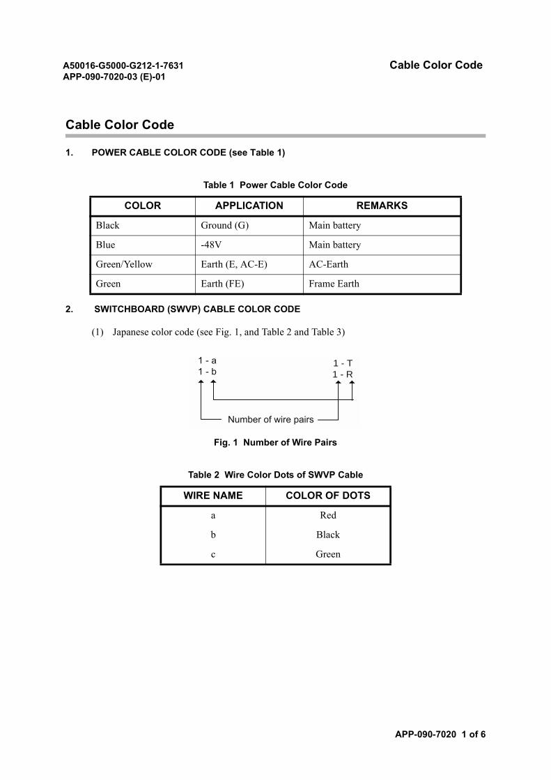
A50016-G5000-G212-1-7631 Cable Color CodeAPP-090-7020-03 (E)-01
APP-090-7020 1 of 6
Cable Color Code
1. POWER CABLE COLOR CODE (see Table 1)
2. SWITCHBOARD (SWVP) CABLE COLOR CODE
(1) Japanese color code (see Fig. 1, and Table 2 and Table 3)
Fig. 1 Number of Wire Pairs
Table 1 Power Cable Color Code
COLOR APPLICATION REMARKS
Black Ground (G) Main battery
Blue -48V Main battery
Green/Yellow Earth (E, AC-E) AC-Earth
Green Earth (FE) Frame Earth
Table 2 Wire Color Dots of SWVP Cable
WIRE NAME COLOR OF DOTS
a Red
b Black
c Green
1 - a1 - b
1 - T1 - R
Number of wire pairs
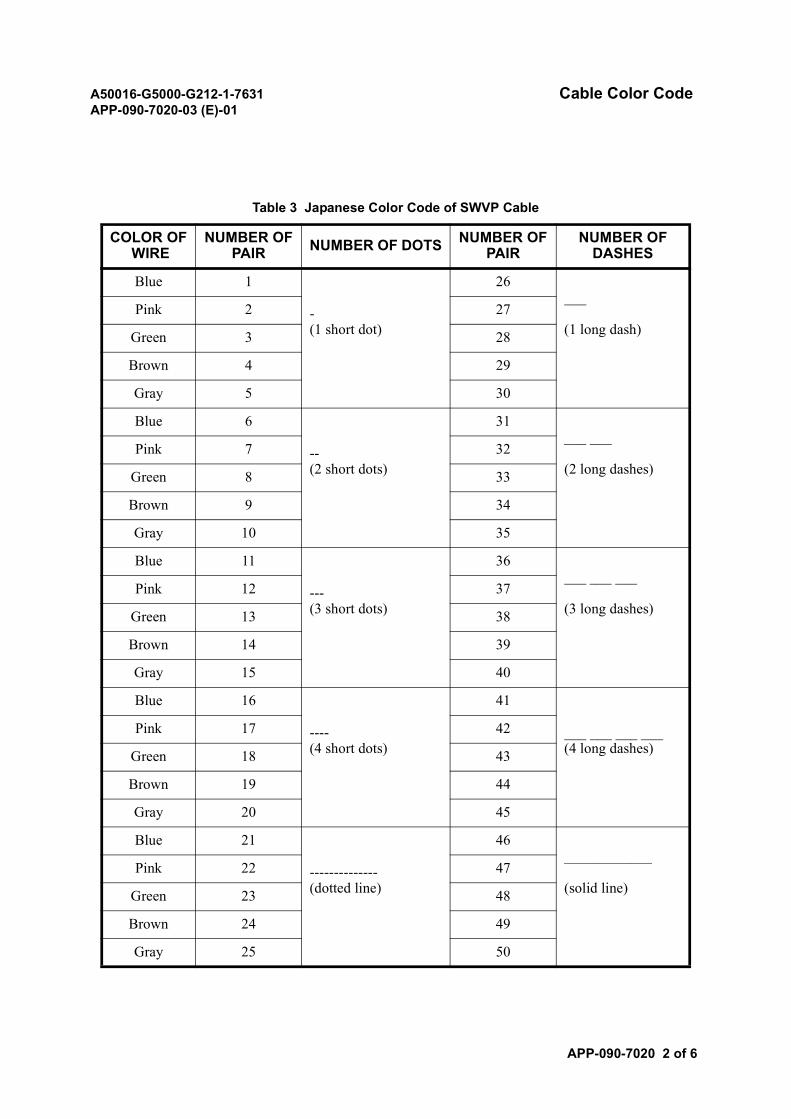
A50016-G5000-G212-1-7631 Cable Color CodeAPP-090-7020-03 (E)-01
APP-090-7020 2 of 6
Table 3 Japanese Color Code of SWVP Cable
COLOR OF WIRE
NUMBER OFPAIR NUMBER OF DOTS NUMBER OF
PAIRNUMBER OF
DASHES
Blue 1
-(1 short dot)
26___
(1 long dash)Pink 2 27
Green 3 28
Brown 4 29
Gray 5 30
Blue 6
--(2 short dots)
31___ ___
(2 long dashes)Pink 7 32
Green 8 33
Brown 9 34
Gray 10 35
Blue 11
---(3 short dots)
36___ ___ ___
(3 long dashes)Pink 12 37
Green 13 38
Brown 14 39
Gray 15 40
Blue 16
----(4 short dots)
41
___ ___ ___ ___(4 long dashes)
Pink 17 42
Green 18 43
Brown 19 44
Gray 20 45
Blue 21
--------------(dotted line)
46____________
(solid line)Pink 22 47
Green 23 48
Brown 24 49
Gray 25 50
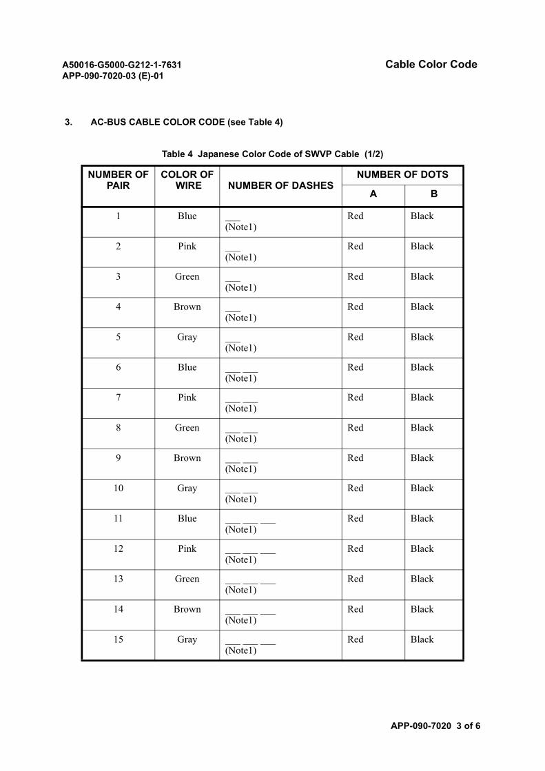
A50016-G5000-G212-1-7631 Cable Color CodeAPP-090-7020-03 (E)-01
APP-090-7020 3 of 6
3. AC-BUS CABLE COLOR CODE (see Table 4)
Table 4 Japanese Color Code of SWVP Cable (1/2)
NUMBER OFPAIR
COLOR OF WIRE NUMBER OF DASHES
NUMBER OF DOTS
A B
1 Blue ___(Note1)
Red Black
2 Pink ___(Note1)
Red Black
3 Green ___(Note1)
Red Black
4 Brown ___(Note1)
Red Black
5 Gray ___(Note1)
Red Black
6 Blue ___ ___(Note1)
Red Black
7 Pink ___ ___(Note1)
Red Black
8 Green ___ ___(Note1)
Red Black
9 Brown ___ ___(Note1)
Red Black
10 Gray ___ ___(Note1)
Red Black
11 Blue ___ ___ ___(Note1)
Red Black
12 Pink ___ ___ ___(Note1)
Red Black
13 Green ___ ___ ___(Note1)
Red Black
14 Brown ___ ___ ___(Note1)
Red Black
15 Gray ___ ___ ___(Note1)
Red Black
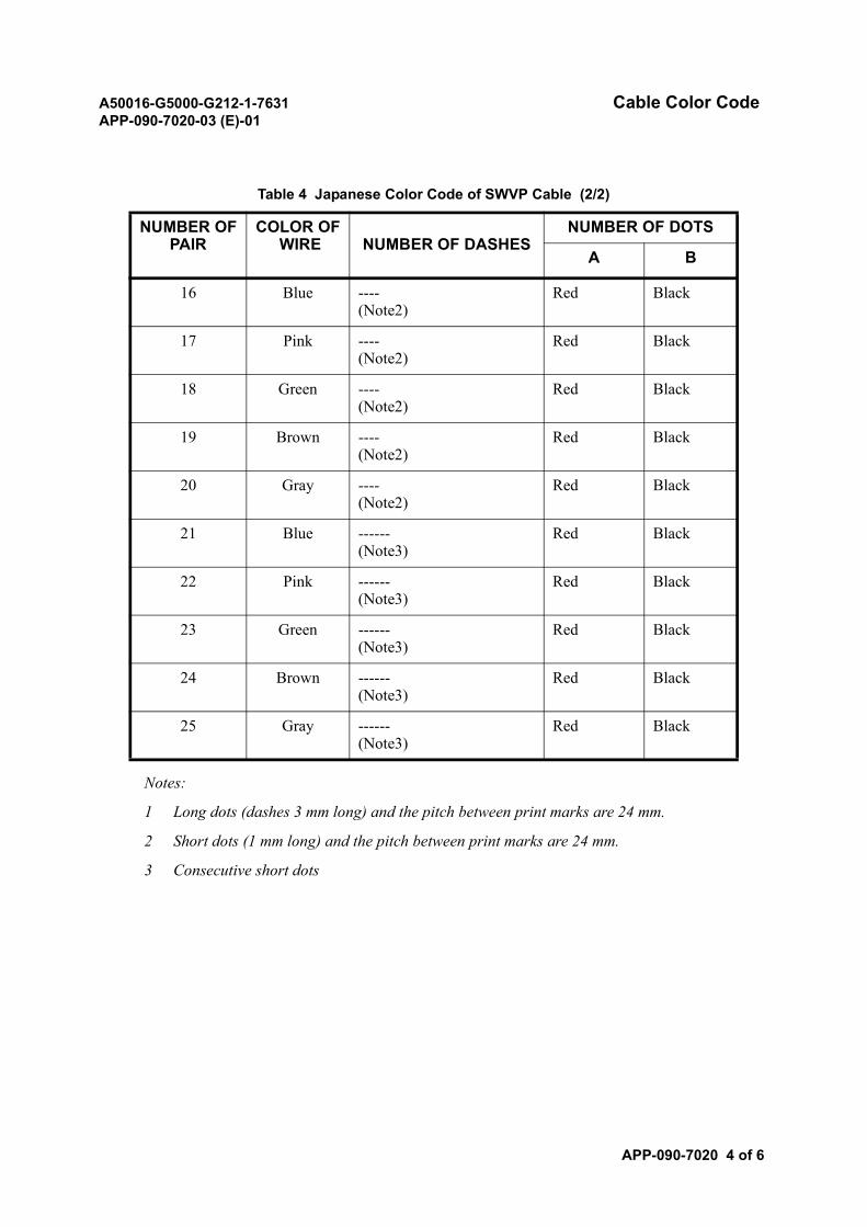
A50016-G5000-G212-1-7631 Cable Color CodeAPP-090-7020-03 (E)-01
APP-090-7020 4 of 6
Notes:
1 Long dots (dashes 3 mm long) and the pitch between print marks are 24 mm.
2 Short dots (1 mm long) and the pitch between print marks are 24 mm.
3 Consecutive short dots
16 Blue ----(Note2)
Red Black
17 Pink ----(Note2)
Red Black
18 Green ----(Note2)
Red Black
19 Brown ----(Note2)
Red Black
20 Gray ----(Note2)
Red Black
21 Blue ------(Note3)
Red Black
22 Pink ------(Note3)
Red Black
23 Green ------(Note3)
Red Black
24 Brown ------(Note3)
Red Black
25 Gray ------(Note3)
Red Black
Table 4 Japanese Color Code of SWVP Cable (2/2)
NUMBER OFPAIR
COLOR OF WIRE NUMBER OF DASHES
NUMBER OF DOTS
A B
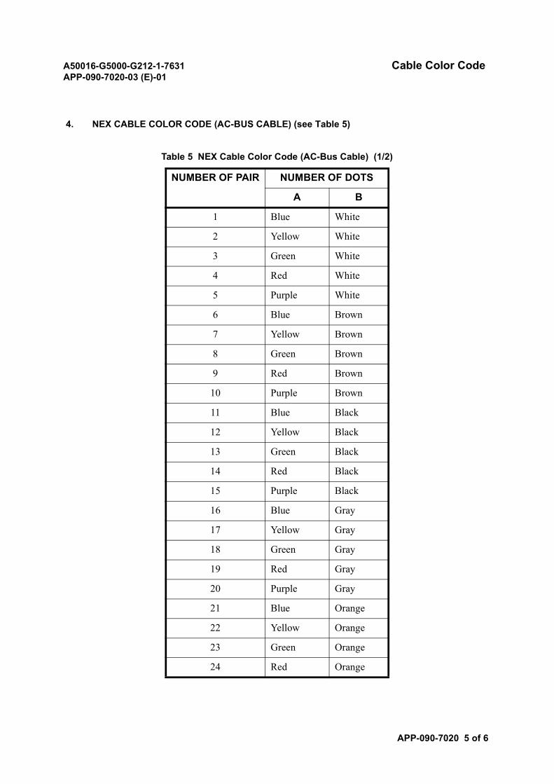
A50016-G5000-G212-1-7631 Cable Color CodeAPP-090-7020-03 (E)-01
APP-090-7020 5 of 6
4. NEX CABLE COLOR CODE (AC-BUS CABLE) (see Table 5)
Table 5 NEX Cable Color Code (AC-Bus Cable) (1/2)
NUMBER OF PAIR NUMBER OF DOTS
A B
1 Blue White
2 Yellow White
3 Green White
4 Red White
5 Purple White
6 Blue Brown
7 Yellow Brown
8 Green Brown
9 Red Brown
10 Purple Brown
11 Blue Black
12 Yellow Black
13 Green Black
14 Red Black
15 Purple Black
16 Blue Gray
17 Yellow Gray
18 Green Gray
19 Red Gray
20 Purple Gray
21 Blue Orange
22 Yellow Orange
23 Green Orange
24 Red Orange

A50016-G5000-G212-1-7631 Cable Color CodeAPP-090-7020-03 (E)-01
APP-090-7020 6 of 6
25 Purple Orange
Table 5 NEX Cable Color Code (AC-Bus Cable) (2/2)
NUMBER OF PAIR NUMBER OF DOTS
A B

A50016-G5000-G212-1-7631ND-57268-706 (E)-01
SECTION 9TOOLS
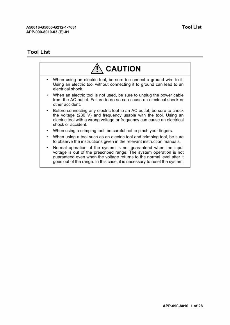
A50016-G5000-G212-1-7631 Tool ListAPP-090-8010-03 (E)-01
APP-090-8010 1 of 28
Tool List
CAUTION• When using an electric tool, be sure to connect a ground wire to it.
Using an electric tool without connecting it to ground can lead to anelectrical shock.
• When an electric tool is not used, be sure to unplug the power cablefrom the AC outlet. Failure to do so can cause an electrical shock orother accident.
• Before connecting any electric tool to an AC outlet, be sure to checkthe voltage (230 V) and frequency usable with the tool. Using anelectric tool with a wrong voltage or frequency can cause an electricalshock or accident.
• When using a crimping tool, be careful not to pinch your fingers.• When using a tool such as an electric tool and crimping tool, be sure
to observe the instructions given in the relevant instruction manuals.• Normal operation of the system is not guaranteed when the input
voltage is out of the prescribed range. The system operation is notguaranteed even when the voltage returns to the normal level after itgoes out of the range. In this case, it is necessary to reset the system.
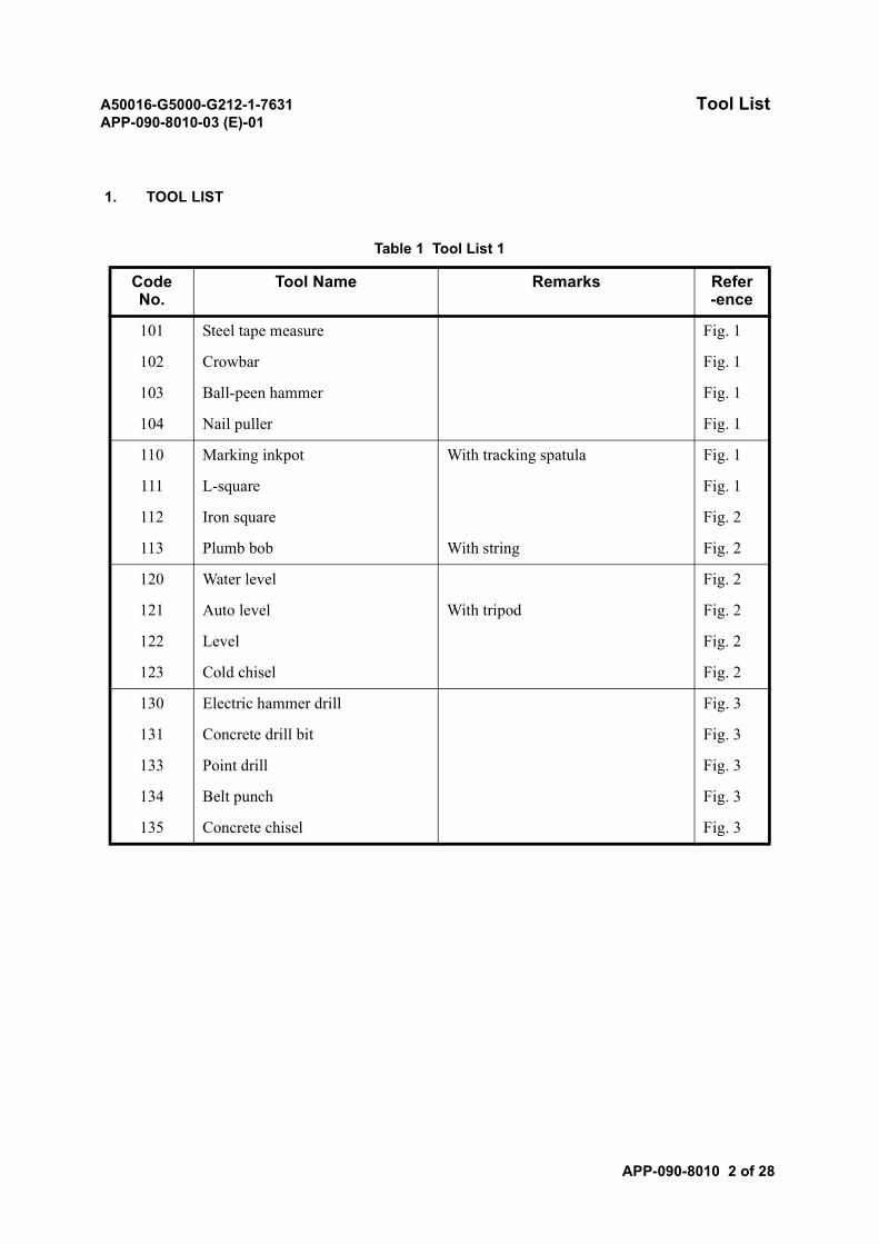
A50016-G5000-G212-1-7631 Tool ListAPP-090-8010-03 (E)-01
APP-090-8010 2 of 28
1. TOOL LIST
Table 1 Tool List 1
Code No.
Tool Name Remarks Refer-ence
101 Steel tape measure Fig. 1
102 Crowbar Fig. 1
103 Ball-peen hammer Fig. 1
104 Nail puller Fig. 1
110 Marking inkpot With tracking spatula Fig. 1
111 L-square Fig. 1
112 Iron square Fig. 2
113 Plumb bob With string Fig. 2
120 Water level Fig. 2
121 Auto level With tripod Fig. 2
122 Level Fig. 2
123 Cold chisel Fig. 2
130 Electric hammer drill Fig. 3
131 Concrete drill bit Fig. 3
133 Point drill Fig. 3
134 Belt punch Fig. 3
135 Concrete chisel Fig. 3
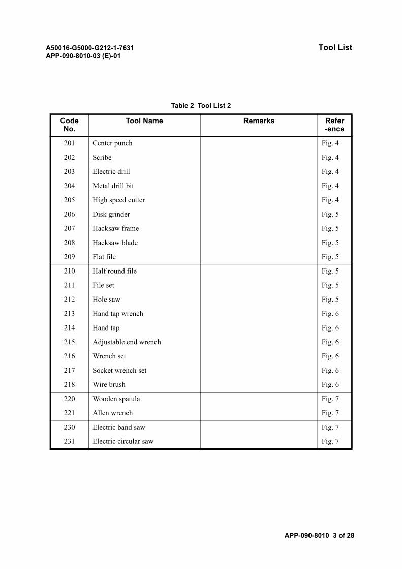
A50016-G5000-G212-1-7631 Tool ListAPP-090-8010-03 (E)-01
APP-090-8010 3 of 28
Table 2 Tool List 2
Code No.
Tool Name Remarks Refer-ence
201 Center punch Fig. 4
202 Scribe Fig. 4
203 Electric drill Fig. 4
204 Metal drill bit Fig. 4
205 High speed cutter Fig. 4
206 Disk grinder Fig. 5
207 Hacksaw frame Fig. 5
208 Hacksaw blade Fig. 5
209 Flat file Fig. 5
210 Half round file Fig. 5
211 File set Fig. 5
212 Hole saw Fig. 5
213 Hand tap wrench Fig. 6
214 Hand tap Fig. 6
215 Adjustable end wrench Fig. 6
216 Wrench set Fig. 6
217 Socket wrench set Fig. 6
218 Wire brush Fig. 6
220 Wooden spatula Fig. 7
221 Allen wrench Fig. 7
230 Electric band saw Fig. 7
231 Electric circular saw Fig. 7
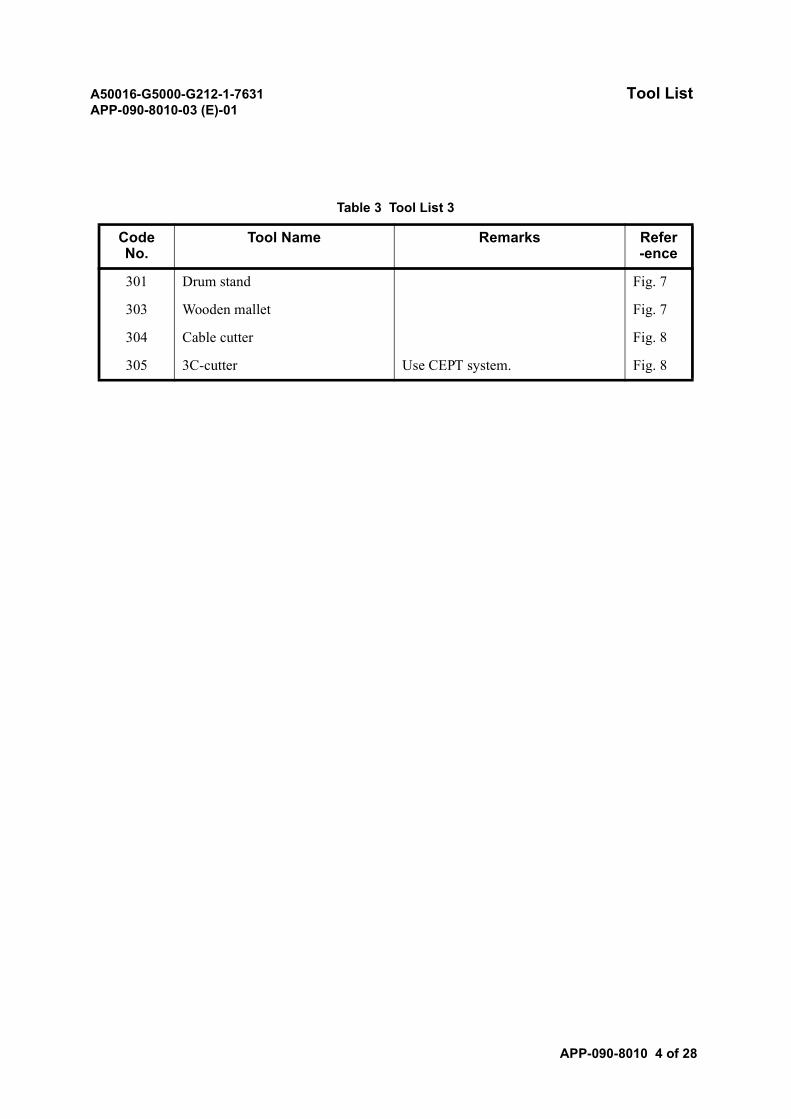
A50016-G5000-G212-1-7631 Tool ListAPP-090-8010-03 (E)-01
APP-090-8010 4 of 28
Table 3 Tool List 3
Code No.
Tool Name Remarks Refer-ence
301 Drum stand Fig. 7
303 Wooden mallet Fig. 7
304 Cable cutter Fig. 8
305 3C-cutter Use CEPT system. Fig. 8
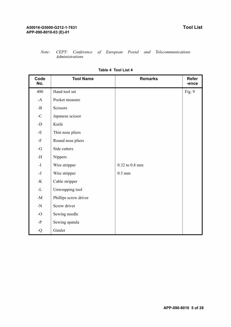
A50016-G5000-G212-1-7631 Tool ListAPP-090-8010-03 (E)-01
APP-090-8010 5 of 28
Note: CEPT: Conference of European Postal and TelecommunicationsAdministrations
Table 4 Tool List 4
Code No.
Tool Name Remarks Refer-ence
400 Hand tool set Fig. 9
-A Pocket measure
-B Scissors
-C Japanese scissor
-D Knife
-E Thin nose pliers
-F Round nose pliers
-G Side cutters
-H Nippers
-I Wire stripper 0.32 to 0.8 mm
-J Wire stripper 0.5 mm
-K Cable stripper
-L Unwrapping tool
-M Phillips screw driver
-N Screw driver
-O Sewing needle
-P Sewing spatula
-Q Gimlet
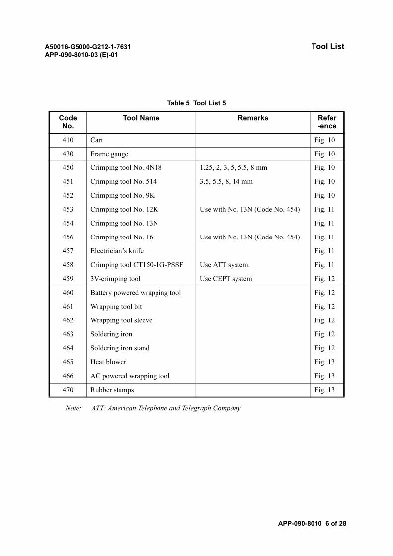
A50016-G5000-G212-1-7631 Tool ListAPP-090-8010-03 (E)-01
APP-090-8010 6 of 28
Note: ATT: American Telephone and Telegraph Company
Table 5 Tool List 5
Code No.
Tool Name Remarks Refer-ence
410 Cart Fig. 10
430 Frame gauge Fig. 10
450 Crimping tool No. 4N18 1.25, 2, 3, 5, 5.5, 8 mm Fig. 10
451 Crimping tool No. 514 3.5, 5.5, 8, 14 mm Fig. 10
452 Crimping tool No. 9K Fig. 10
453 Crimping tool No. 12K Use with No. 13N (Code No. 454) Fig. 11
454 Crimping tool No. 13N Fig. 11
456 Crimping tool No. 16 Use with No. 13N (Code No. 454) Fig. 11
457 Electrician’s knife Fig. 11
458 Crimping tool CT150-1G-PSSF Use ATT system. Fig. 11
459 3V-crimping tool Use CEPT system Fig. 12
460 Battery powered wrapping tool Fig. 12
461 Wrapping tool bit Fig. 12
462 Wrapping tool sleeve Fig. 12
463 Soldering iron Fig. 12
464 Soldering iron stand Fig. 12
465 Heat blower Fig. 13
466 AC powered wrapping tool Fig. 13
470 Rubber stamps Fig. 13
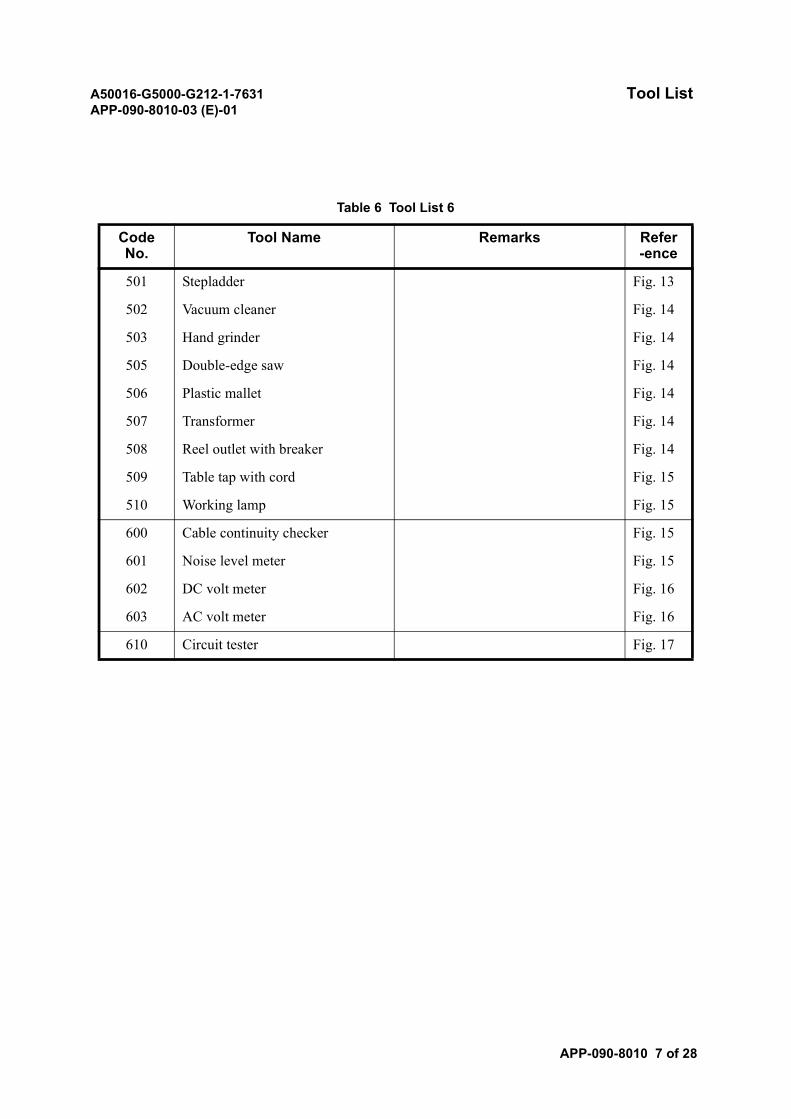
A50016-G5000-G212-1-7631 Tool ListAPP-090-8010-03 (E)-01
APP-090-8010 7 of 28
Table 6 Tool List 6
Code No.
Tool Name Remarks Refer-ence
501 Stepladder Fig. 13
502 Vacuum cleaner Fig. 14
503 Hand grinder Fig. 14
505 Double-edge saw Fig. 14
506 Plastic mallet Fig. 14
507 Transformer Fig. 14
508 Reel outlet with breaker Fig. 14
509 Table tap with cord Fig. 15
510 Working lamp Fig. 15
600 Cable continuity checker Fig. 15
601 Noise level meter Fig. 15
602 DC volt meter Fig. 16
603 AC volt meter Fig. 16
610 Circuit tester Fig. 17
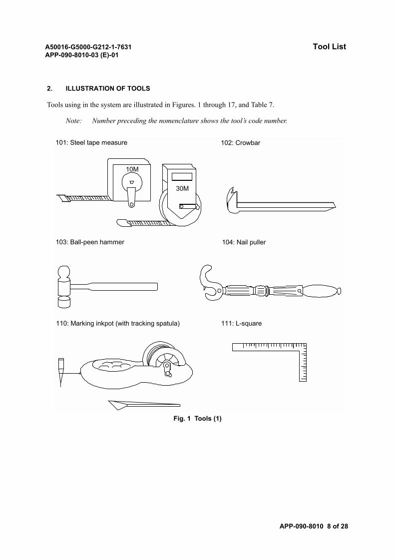
A50016-G5000-G212-1-7631 Tool ListAPP-090-8010-03 (E)-01
APP-090-8010 8 of 28
2. ILLUSTRATION OF TOOLS
Tools using in the system are illustrated in Figures. 1 through 17, and Table 7.
Note: Number preceding the nomenclature shows the tool’s code number.
Fig. 1 Tools (1)
101: Steel tape measure
10M
30M
102: Crowbar
103: Ball-peen hammer 104: Nail puller
110: Marking inkpot (with tracking spatula) 111: L-square
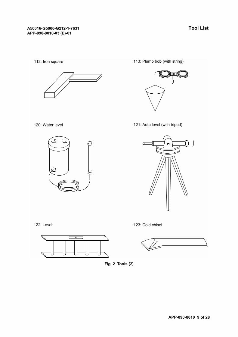
A50016-G5000-G212-1-7631 Tool ListAPP-090-8010-03 (E)-01
APP-090-8010 9 of 28
Fig. 2 Tools (2)
112: Iron square 113: Plumb bob (with string)
120: Water level 121: Auto level (with tripod)
122: Level 123: Cold chisel
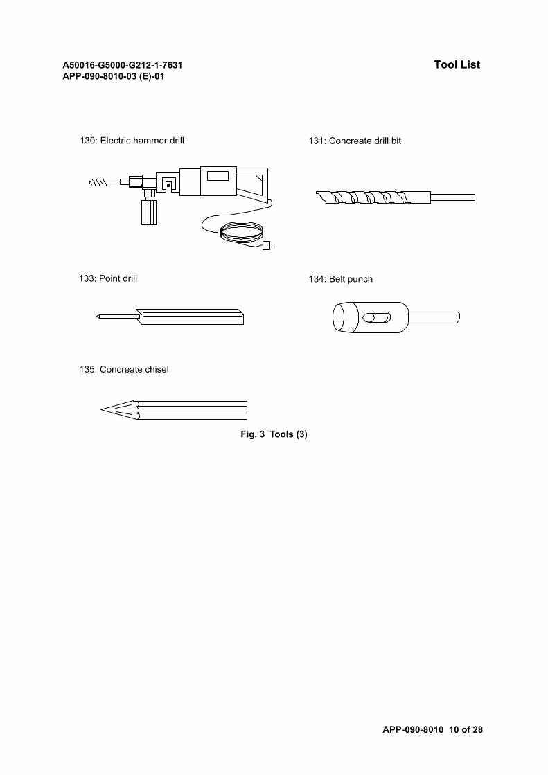
A50016-G5000-G212-1-7631 Tool ListAPP-090-8010-03 (E)-01
APP-090-8010 10 of 28
Fig. 3 Tools (3)
130: Electric hammer drill 131: Concreate drill bit
133: Point drill 134: Belt punch
135: Concreate chisel
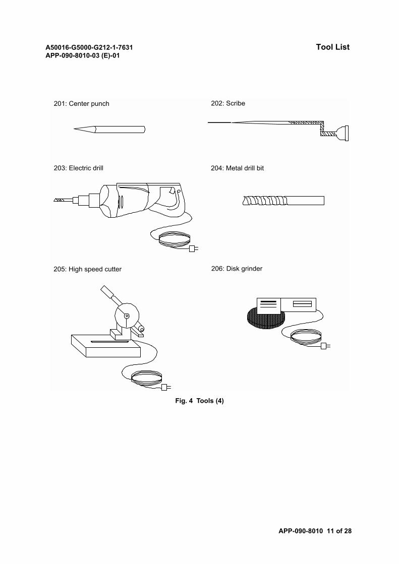
A50016-G5000-G212-1-7631 Tool ListAPP-090-8010-03 (E)-01
APP-090-8010 11 of 28
Fig. 4 Tools (4)
201: Center punch 202: Scribe
203: Electric drill 204: Metal drill bit
205: High speed cutter 206: Disk grinder
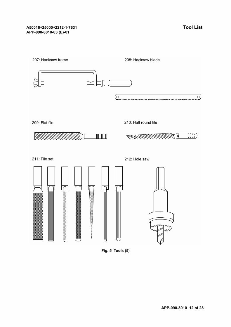
A50016-G5000-G212-1-7631 Tool ListAPP-090-8010-03 (E)-01
APP-090-8010 12 of 28
Fig. 5 Tools (5)
207: Hacksaw frame 208: Hacksaw blade
209: Flat file 210: Half round file
211: File set 212: Hole saw
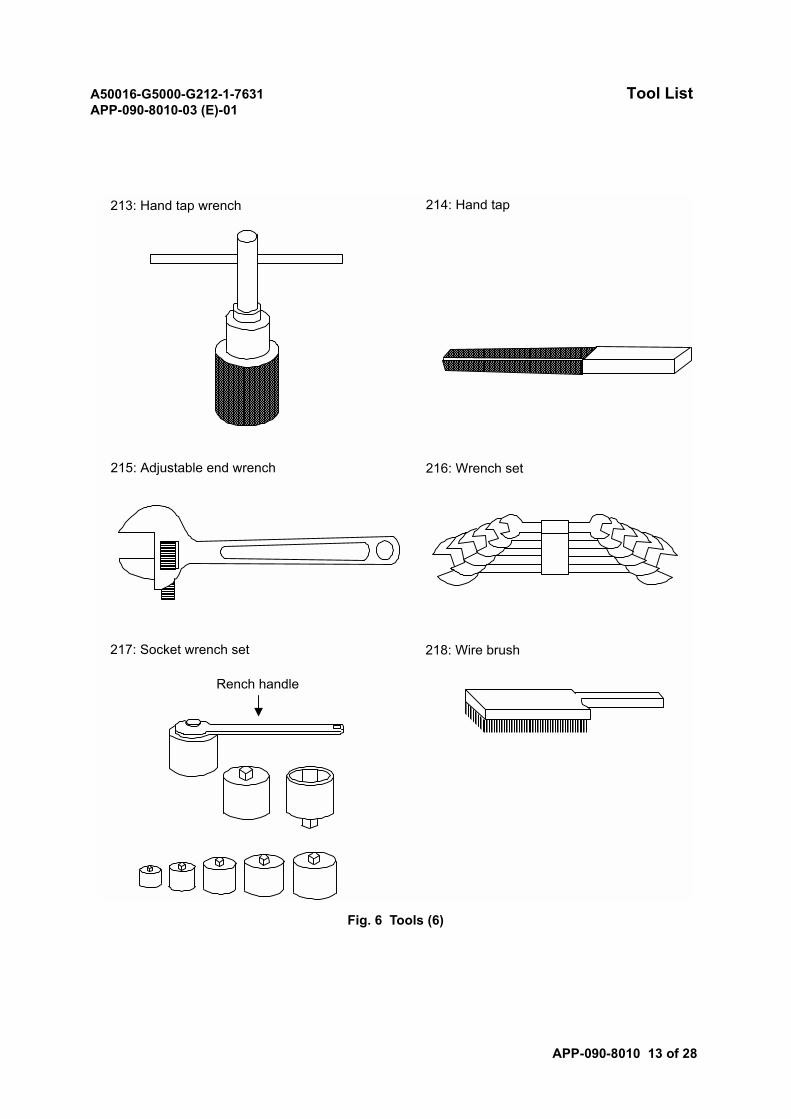
A50016-G5000-G212-1-7631 Tool ListAPP-090-8010-03 (E)-01
APP-090-8010 13 of 28
Fig. 6 Tools (6)
213: Hand tap wrench 214: Hand tap
215: Adjustable end wrench 216: Wrench set
217: Socket wrench set
Rench handle
218: Wire brush
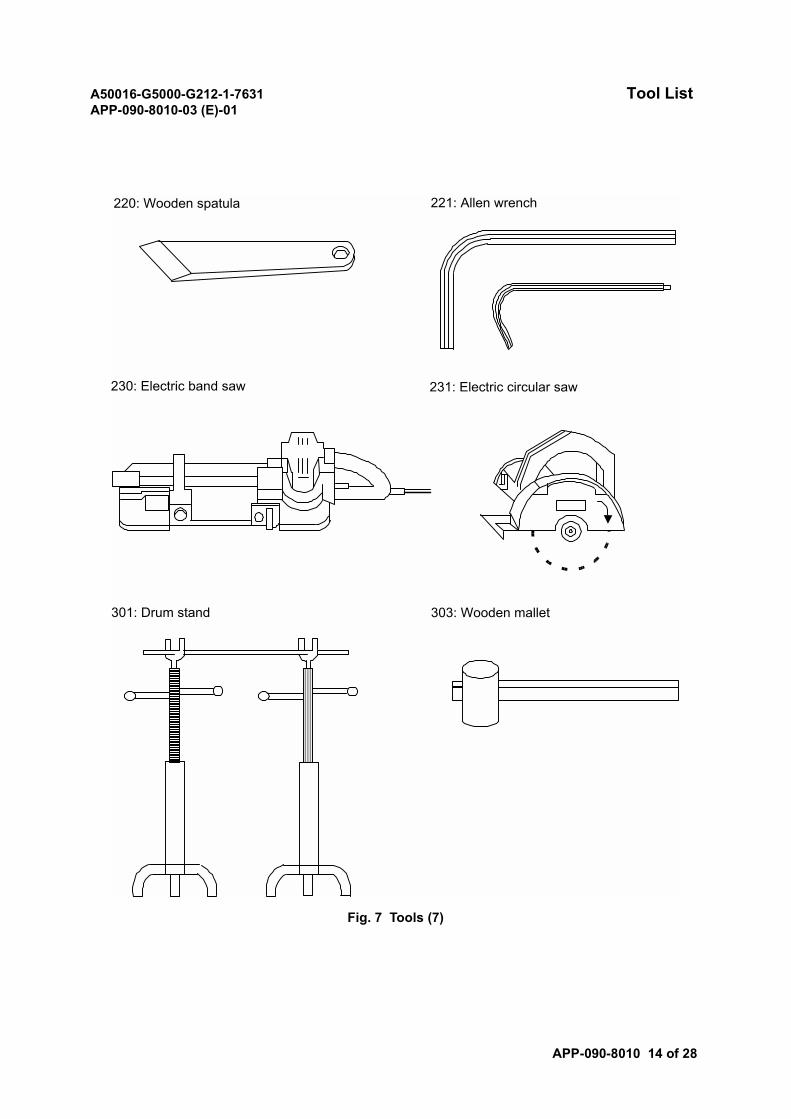
A50016-G5000-G212-1-7631 Tool ListAPP-090-8010-03 (E)-01
APP-090-8010 14 of 28
Fig. 7 Tools (7)
220: Wooden spatula 221: Allen wrench
230: Electric band saw 231: Electric circular saw
301: Drum stand 303: Wooden mallet
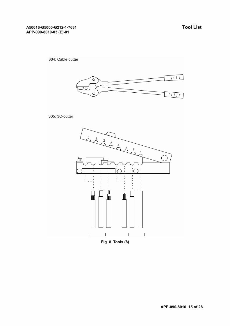
A50016-G5000-G212-1-7631 Tool ListAPP-090-8010-03 (E)-01
APP-090-8010 15 of 28
Fig. 8 Tools (8)
304: Cable cutter
305: 3C-cutter
43 2
5 43 2
1
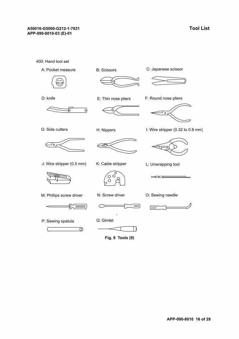
A50016-G5000-G212-1-7631 Tool ListAPP-090-8010-03 (E)-01
APP-090-8010 16 of 28
Fig. 9 Tools (9)
400: Hand tool set
A: Pocket measure B: Scissors C: Japanese scissor
D: knife E: Thin nose pliers F: Round nose pliers
G: Side cutters H: Nippers I: Wire stripper (0.32 to 0.8 mm)
J: Wire stripper (0.5 mm) K: Cable stripper L: Unwrapping tool
M: Phillips screw driver N: Screw driver O: Sewing needle
P: Sewing spatula Q: Gimlet
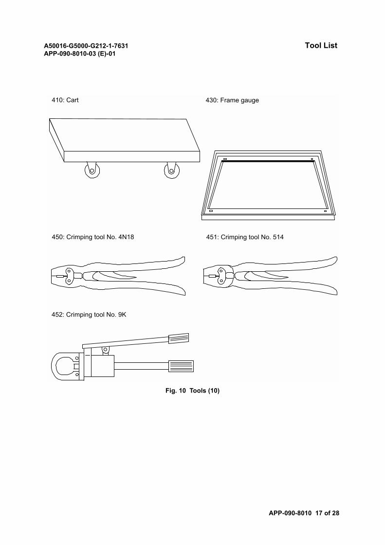
A50016-G5000-G212-1-7631 Tool ListAPP-090-8010-03 (E)-01
APP-090-8010 17 of 28
Fig. 10 Tools (10)
410: Cart 430: Frame gauge
450: Crimping tool No. 4N18 451: Crimping tool No. 514
452: Crimping tool No. 9K
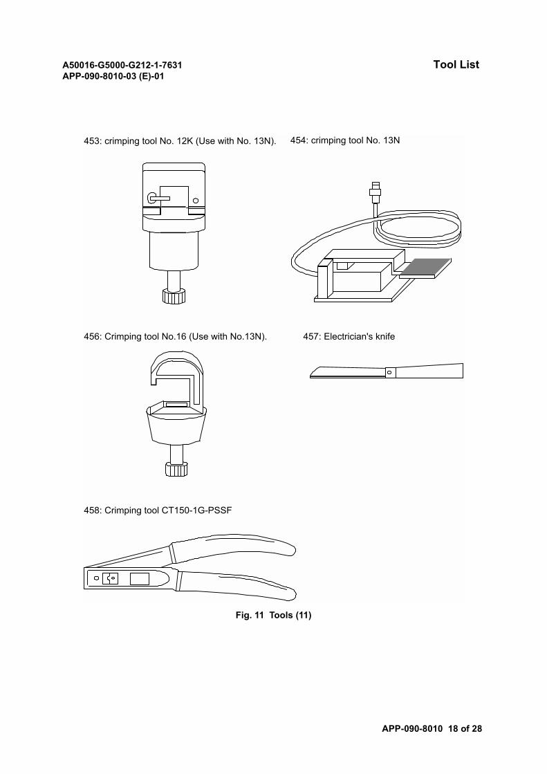
A50016-G5000-G212-1-7631 Tool ListAPP-090-8010-03 (E)-01
APP-090-8010 18 of 28
Fig. 11 Tools (11)
456: Crimping tool No.16 (Use with No.13N). 457: Electrician's knife
453: crimping tool No. 12K (Use with No. 13N). 454: crimping tool No. 13N
458: Crimping tool CT150-1G-PSSF
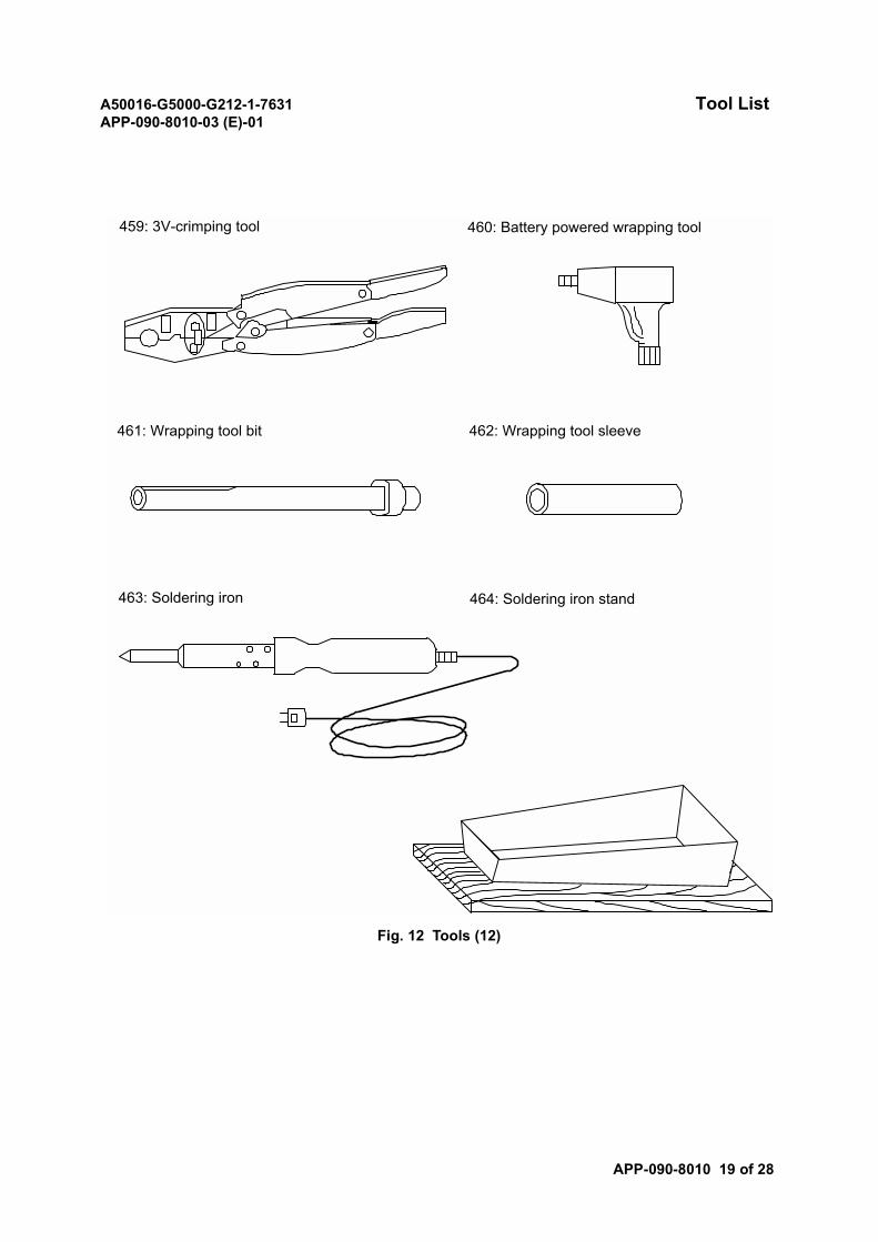
A50016-G5000-G212-1-7631 Tool ListAPP-090-8010-03 (E)-01
APP-090-8010 19 of 28
Fig. 12 Tools (12)
459: 3V-crimping tool 460: Battery powered wrapping tool
461: Wrapping tool bit 462: Wrapping tool sleeve
463: Soldering iron 464: Soldering iron stand
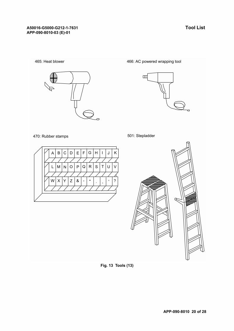
A50016-G5000-G212-1-7631 Tool ListAPP-090-8010-03 (E)-01
APP-090-8010 20 of 28
Fig. 13 Tools (13)
465: Heat blower 466: AC powered wrapping tool
470: Rubber stamps
A B C D E F G H I J K
L M N O P Q R S T U V
W X Y Z & - " . , ' ?
501: Stepladder
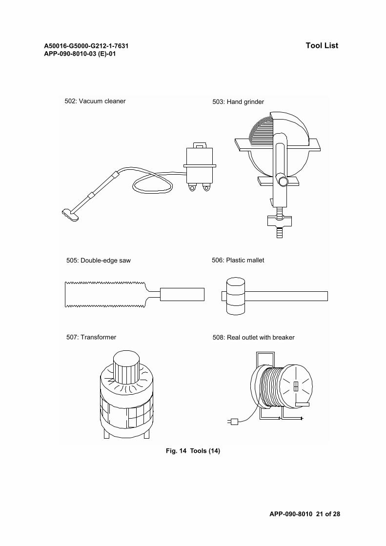
A50016-G5000-G212-1-7631 Tool ListAPP-090-8010-03 (E)-01
APP-090-8010 21 of 28
Fig. 14 Tools (14)
502: Vacuum cleaner 503: Hand grinder
505: Double-edge saw 506: Plastic mallet
507: Transformer 508: Real outlet with breaker
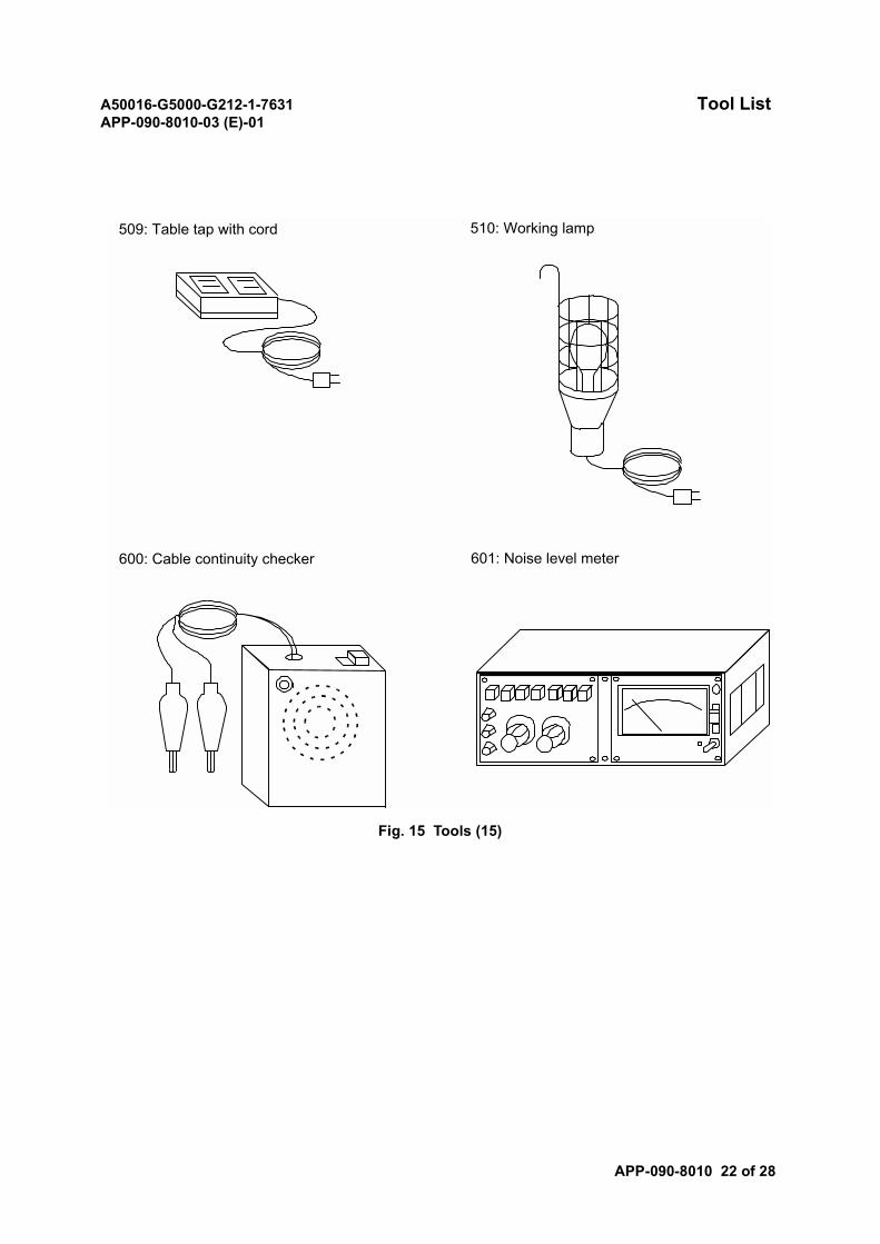
A50016-G5000-G212-1-7631 Tool ListAPP-090-8010-03 (E)-01
APP-090-8010 22 of 28
Fig. 15 Tools (15)
509: Table tap with cord 510: Working lamp
600: Cable continuity checker 601: Noise level meter
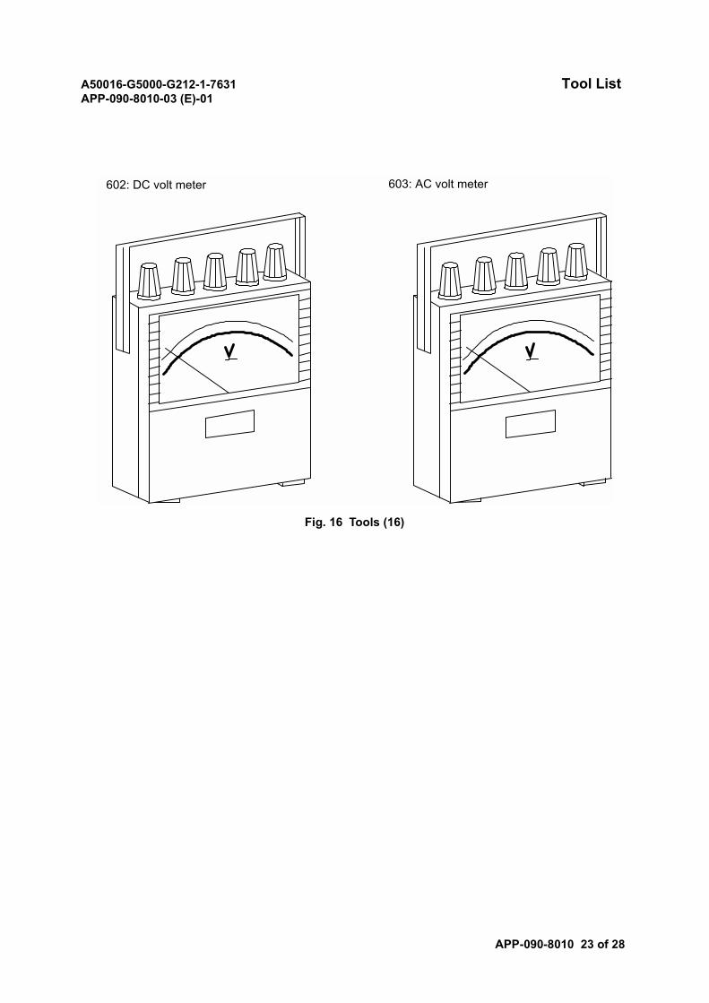
A50016-G5000-G212-1-7631 Tool ListAPP-090-8010-03 (E)-01
APP-090-8010 23 of 28
Fig. 16 Tools (16)
602: DC volt meter 603: AC volt meter
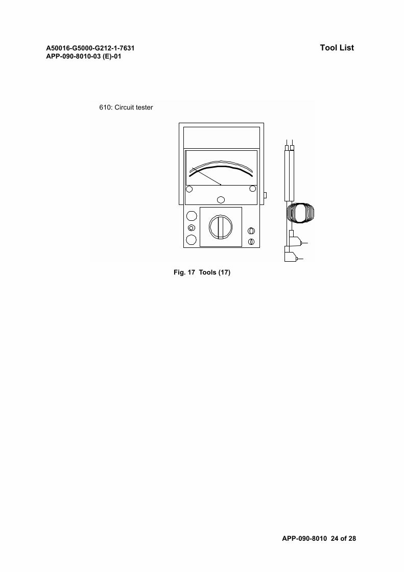
A50016-G5000-G212-1-7631 Tool ListAPP-090-8010-03 (E)-01
APP-090-8010 24 of 28
Fig. 17 Tools (17)
610: Circuit tester
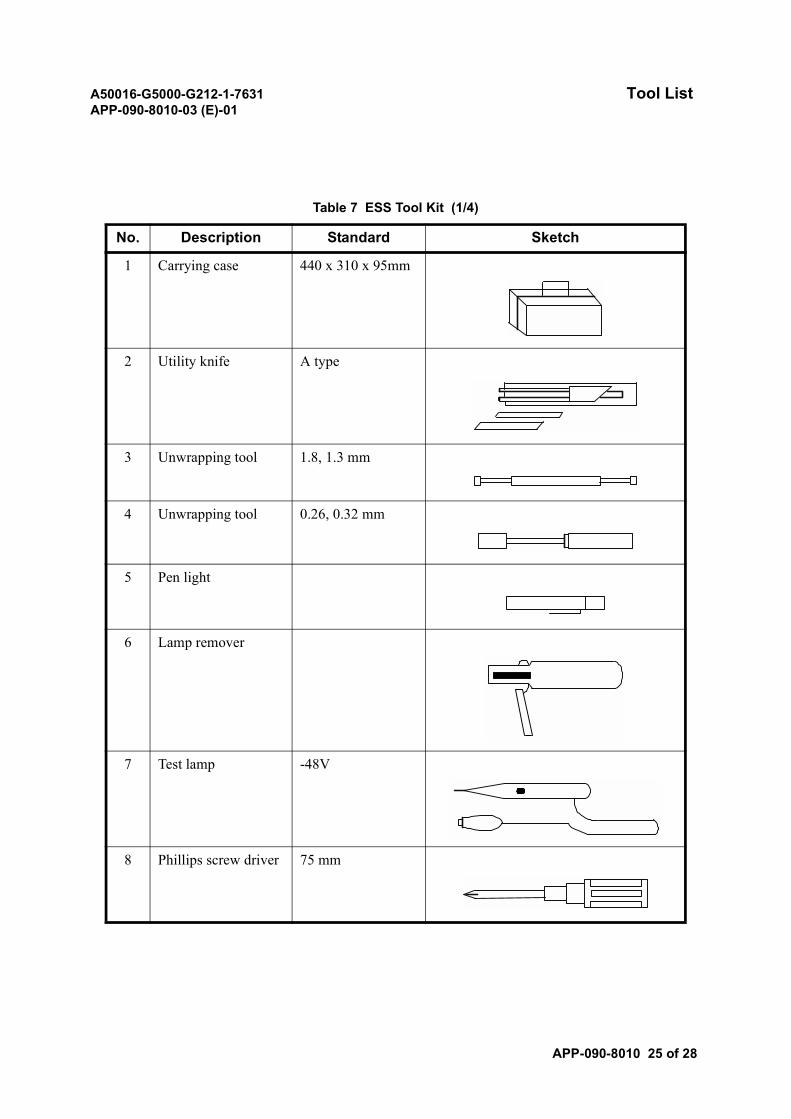
A50016-G5000-G212-1-7631 Tool ListAPP-090-8010-03 (E)-01
APP-090-8010 25 of 28
Table 7 ESS Tool Kit (1/4)
No. Description Standard Sketch
1 Carrying case 440 x 310 x 95mm
2 Utility knife A type
3 Unwrapping tool 1.8, 1.3 mm
4 Unwrapping tool 0.26, 0.32 mm
5 Pen light
6 Lamp remover
7 Test lamp -48V
8 Phillips screw driver 75 mm
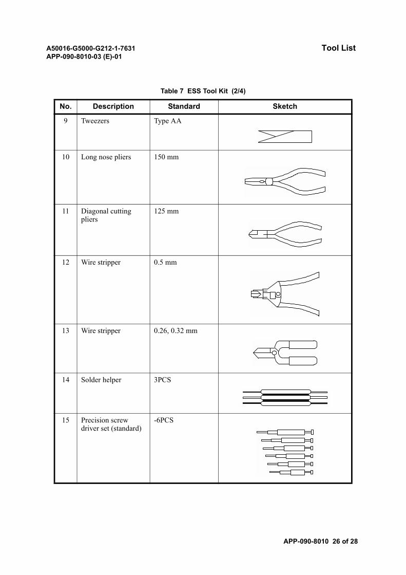
A50016-G5000-G212-1-7631 Tool ListAPP-090-8010-03 (E)-01
APP-090-8010 26 of 28
9 Tweezers Type AA
10 Long nose pliers 150 mm
11 Diagonal cutting pliers
125 mm
12 Wire stripper 0.5 mm
13 Wire stripper 0.26, 0.32 mm
14 Solder helper 3PCS
15 Precision screw driver set (standard)
-6PCS
Table 7 ESS Tool Kit (2/4)
No. Description Standard Sketch
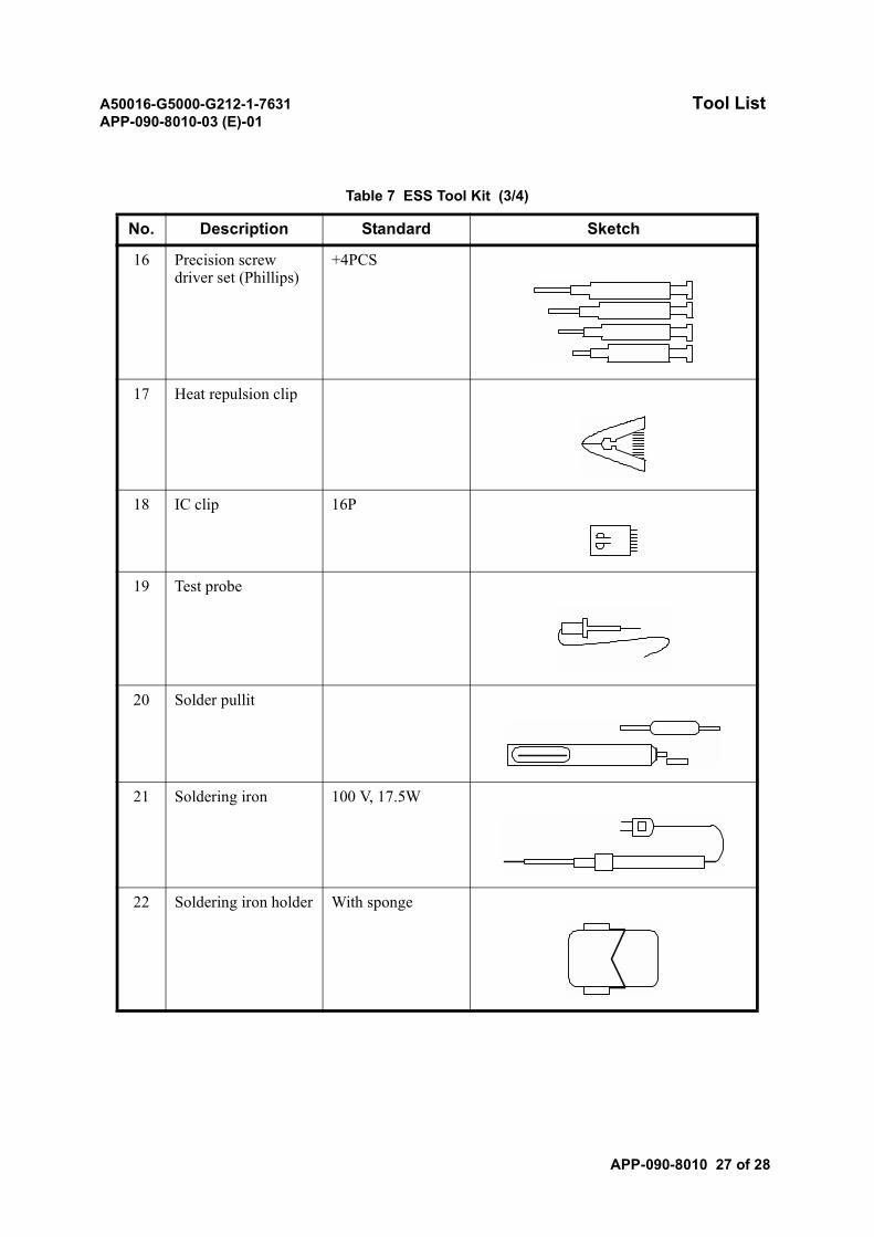
A50016-G5000-G212-1-7631 Tool ListAPP-090-8010-03 (E)-01
APP-090-8010 27 of 28
16 Precision screw driver set (Phillips)
+4PCS
17 Heat repulsion clip
18 IC clip 16P
19 Test probe
20 Solder pullit
21 Soldering iron 100 V, 17.5W
22 Soldering iron holder With sponge
Table 7 ESS Tool Kit (3/4)
No. Description Standard Sketch
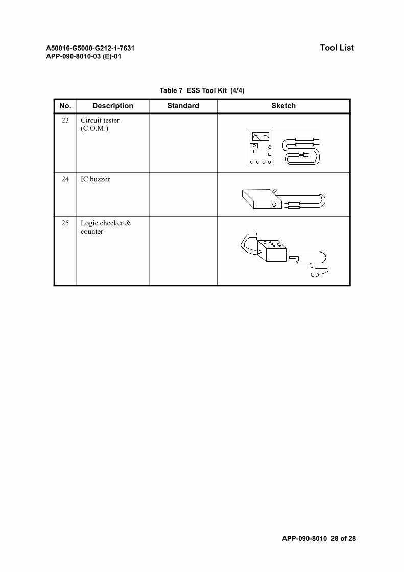
A50016-G5000-G212-1-7631 Tool ListAPP-090-8010-03 (E)-01
APP-090-8010 28 of 28
23 Circuit tester (C.O.M.)
24 IC buzzer
25 Logic checker & counter
Table 7 ESS Tool Kit (4/4)
No. Description Standard Sketch

A50016-G5000-G212-1-7631ND-57268-706 (E)-01
SECTION 10HOW TO READ THE INSTALLATION DRAWINGS

A50016-G5000-G212-1-7631 Physical DrawingAPP-090-8500-02 (E)-01
APP-090-8500 1 of 30
Physical Drawing
In this section, the following drawings are described.
(1) SYSTEM COMPOSITION
• Equipment Information
• Trunking Diagram
• Floor Layout
• Face Layout
(2) APPLICATION ASSIGNMENT
• Hub Assignment
• I/O Assignment
• LSM Assignment
(3) ALARM ASSIGNMENT
• Alarm Assignment
(4) DF TERMINAL
• DDF Face Layout (Reference Only)
• FDF Face Layout (Reference Only)
• IDF Assignment
• DDF Assignment (Reference Only)
• FDF Assignment (Reference Only)
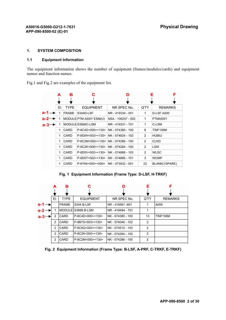
A50016-G5000-G212-1-7631 Physical DrawingAPP-090-8500-02 (E)-01
APP-090-8500 2 of 30
1. SYSTEM COMPOSITION
1.1 Equipment Information
The equipment information shows the number of equipment (frames/modules/cards) and equipmentnames and function names.
Fig.1 and Fig.2 are examples of the equipment list.
Fig. 1 Equipment Information (Frame Type: D-LSF, H-TRKF)
Fig. 2 Equipment Information (Frame Type: B-LSF, A-PRF, C-TRKF, E-TRKF)
A B C D E F
a-1a-2a-3
EI TYPE EQUIPMENT NR SPEC No, Q'TY REMARKS1 FRAME S344D-LSF NR - 419334 - 001 1 D-LSF A000
1 MODULES3668C-LSM NR - 419331 - 701 1 C-LSM
1 CARD P-8C4D<000><130> NK - 074380 - 100 8 TINF156M
1 CARD P-8D0H<003><130> NK - 074824 - 102 2 HUBIU
1 CARD P-8C2M<000><130> NK - 074286 - 100 2 CLKD
1 CARD P-8C2K<000><130> NK - 074284 - 100 2 LSW
P-8D0V<002><130> NK - 074868 - 103 2 WLSC1 CARD
1 CARD P-8D0T<002><130> NK - 074866 - 101
1 CARD
1 MODULE PTM ASSY ESM(U) NSA - 106257 - 002 1 PTMASSY
P-8Y94<000><000> NK - 073932 - 001 22 BLANK(1SPARE)
3 WCMP
22 CARD P-8C2M<000><130> NK - 074286 - 100
2 CARD P-8C2K<000><130> NK - 074284 - 100 2
2 CARD P-8C6Q<002><130> NK - 074510 - 103 2
2 CARD P-8B7S<003><130> NK - 074046 - 102 2
2 CARD P-8C4D<000><130> NK - 074380 - 100 13 TINF156M
1 MODULE S3668 B-LSM NR - 418494 - 701 1
FRAME S344 B-LSF NR - 418561 -801 1 A000
NR SPEC No, Q'TY REMARKSEI TYPE EQUIPMENT
A B C D E F
a-1a-2a-3

A50016-G5000-G212-1-7631 Physical DrawingAPP-090-8500-02 (E)-01
APP-090-8500 3 of 30
For each alphabet character used in Fig.1 and Fig.2, refer to the following:
A: Equipment Information (EI)
a-1 Blank: Not assigned
a-2 1: Current equipment
a-3 2: Additional equipment
B: Equipment type
C: Equipment name (Part name)
D: NEC provisional manufacturing specification number (Part No.)
E: Number of equipment (frames/modules/cards) installed in an office
F: Remarks
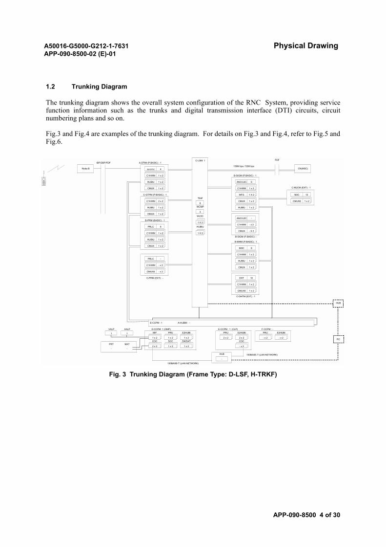
A50016-G5000-G212-1-7631 Physical DrawingAPP-090-8500-02 (E)-01
APP-090-8500 4 of 30
1.2 Trunking Diagram
The trunking diagram shows the overall system configuration of the RNC System, providing servicefunction information such as the trunks and digital transmission interface (DTI) circuits, circuitnumbering plans and so on.
Fig.3 and Fig.4 are examples of the trunking diagram. For details on Fig.3 and Fig.4, refer to Fig.5 andFig.6.
Fig. 3 Trunking Diagram (Frame Type: D-LSF, H-TRKF)
C-M2CM (EXT) : 1
CMUX - X 2
B-SIGM (P.BASIC): -
M2C
CMUXE
ANC/U2C -
CMUX
PRU
-
- x 2COC
- x 2
2 x 2
100BASE-T (LAN NETWORK)
- x 2
HUB
E2HUBI
2 x 2
PRU E2HUBI
1 x 2
DHT
C-DHTM (EXT) : 1
CMUX 1 x 2
10
CMUX
C1HWM
C1HWM 1 x 2
HUBIU 1 x 2
1 x 2
B-PRM (BASIC) : 1
PRLC -
PRLC 8
C1HWM 1 x 2
HUBIU 1 x 2
1 x 2
- x 2
CMUXE - x 2
C-PRM (EXT) : -
100BASE-T (LAN NETWORK)
SCC
1 x 2
COC
VALPMIF
1 x 2
2 x 2 1 x 2
AALP
1 1
PRT MAT
- -
E2HUBI
1 x 2
PRU
DK/DAT1 x 2
E-CCPM : 1 A-HUBM : -
D-CCPM: 1 (OMP) E-CCPM : 1 (CLP) F-CCPM : -
IDF/DDF/FDF
GMUX 1 x 2
HUBIU
C1HWM 2 x 2
1 x 2
CMUX 1 x 2
C-GTPM (P.BASIC) : 1
Node-B 2M DTIC 4
C1HWM 1 x 2
6
FDF
HUBIU 1 x 2
CN(MSC)
C-LSM: 1
B-SIGM (P.BASIC) : 1
A-DTIM (P.BASIC) : 1
ANC/U2C
1 X 2
RC
156M bps / 52M bps
WCMP
3
B-MHM (P.BASIC) : 1
TINFMFG 1 X 2
8
HUB
WLSC
C1HWM 1 x 2
CMUXE
MHC 8
1 X 2
HUBIU
12
1 x 2
C1HWM 1 x 2
HUBIU 1 x 2
C1HWM - x 2
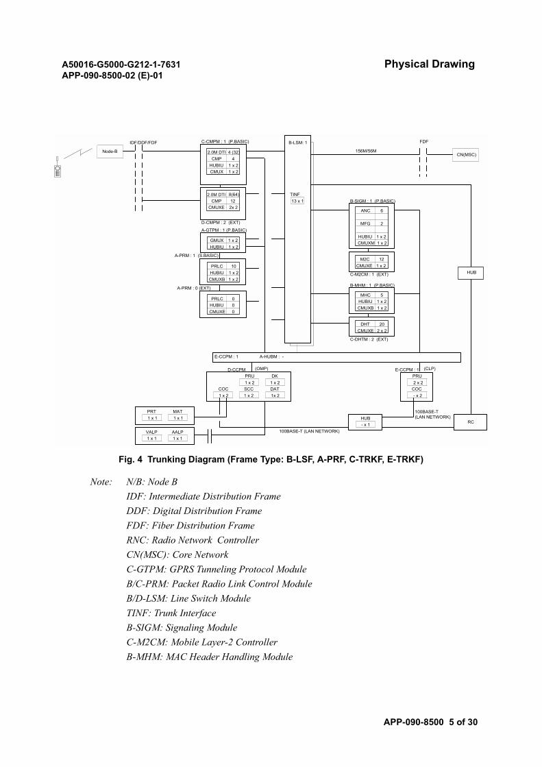
A50016-G5000-G212-1-7631 Physical DrawingAPP-090-8500-02 (E)-01
APP-090-8500 5 of 30
Fig. 4 Trunking Diagram (Frame Type: B-LSF, A-PRF, C-TRKF, E-TRKF)
Note: N/B: Node BIDF: Intermediate Distribution FrameDDF: Digital Distribution FrameFDF: Fiber Distribution FrameRNC: Radio Network ControllerCN(MSC): Core NetworkC-GTPM: GPRS Tunneling Protocol ModuleB/C-PRM: Packet Radio Link Control ModuleB/D-LSM: Line Switch ModuleTINF: Trunk InterfaceB-SIGM: Signaling ModuleC-M2CM: Mobile Layer-2 ControllerB-MHM: MAC Header Handling Module
CN(MSC)
CMUXE 0
2.0M DTI 8(64)CMP 12
CMUXE 2x 2
PRT MAT1 x 1 1 x 1
100BASE-T (LAN NETWORK)- x 1
100BASE-T(LAN NETWORK)HUB
1 x 2 1 x 2 - x 2COC SCC COC
1x 2DAT
2 x 2
D-CMPM : 2 (EXT)
PRU DK1 x 2
A-PRM : 1 (S.BASIC)
1 x 2
HUBIU 1 x 2
D-CCPM (OMP)
PRLCHUBIU 0 1 x 2
ANC 6
CMUXB
MFG 2
MHC 5
2.0M DTI 4 (32)
B-SIGM : 1 (P.BASIC)
CMUXE
1 x 2CMUX 1 x 2
FDFIDF/DDF/FDF B-LSM: 1
Node-B
C-CMPM : 1 (P.BASIC)
CMP 4
12
1 x 2HUBIU 1 x 2CMUXM
DHT
HUBIU
M2C
B-MHM : 1 (P.BASIC)
13 x 1TINF
A-GTPM : 1 (P.BASIC)
CMUXE 2 x 2
E-CCPM : 1
0
C-DHTM : 2 (EXT)
E-CCPM : 1 A-HUBM : -
PRU
1 x 2
20
C-M2CM : 1 (EXT)
GMUX 1 x 2HUBIU 1 x 2
CMUXB 1 x 2
A-PRM : 0 (EXT)
PRLC 10HUBIU 1 x 2 HUB
RC
1 x 1 1 x 1VALP AALP
(CLP)
156M/56M

A50016-G5000-G212-1-7631 Physical DrawingAPP-090-8500-02 (E)-01
APP-090-8500 6 of 30
B/C-DHTM: Diversity Handover TrunkD/E-CCPM: Central Control Processor ModuleA-HUBM: HUB ModuleHUB: Hub (for Ethernet)OMP: Operation and Maintenance ProcessorPRU: Processor UnitDK: DiskCOC: Communication ControllerSCC: SCSI ControllerDAT Digital Audio TapePRT: PrinterMAT: Maintenance and Administration TerminalVALP: Visual Alarm PanelAALP: Audible Alarm PanelCLP: Call Processor
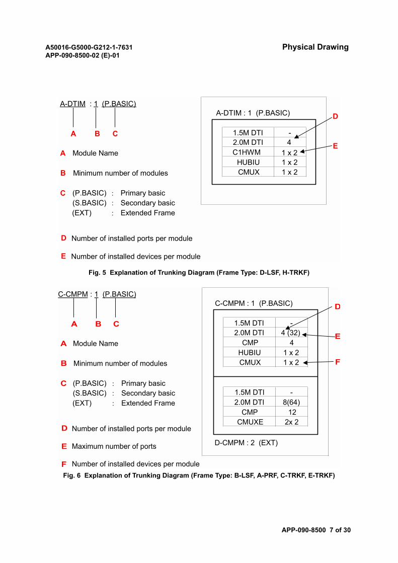
A50016-G5000-G212-1-7631 Physical DrawingAPP-090-8500-02 (E)-01
APP-090-8500 7 of 30
Fig. 5 Explanation of Trunking Diagram (Frame Type: D-LSF, H-TRKF)
Fig. 6 Explanation of Trunking Diagram (Frame Type: B-LSF, A-PRF, C-TRKF, E-TRKF)
A-DTIM : 1 (P.BASIC)A-DTIM : 1 (P.BASIC)
A B C 1.5M DTI -2.0M DTI 4
A Module Name C1HWMHUBIU 1 x 2
B Minimum number of modules CMUX 1 x 2
C (P.BASIC) : Primary basic(S.BASIC) : Secondary basic(EXT) : Extended Frame
D
E
D
E
Number of installed ports per module
Number of installed devices per module
1 x 2
C-CMPM : 1 (P.BASIC)C-CMPM : 1 (P.BASIC)
A B C 1.5M DTI -2.0M DTI 4 (32)
A Module Name CMP 4HUBIU 1 x 2
B Minimum number of modules CMUX 1 x 2
C (P.BASIC) : Primary basic(S.BASIC) : Secondary basic 1.5M DTI -(EXT) : Extended Frame 2.0M DTI 8(64)
CMP 12CMUXE 2x 2
D-CMPM : 2 (EXT)
D
E
F
D
E
F
Number of installed ports per module
Maximum number of ports
Number of installed devices per module
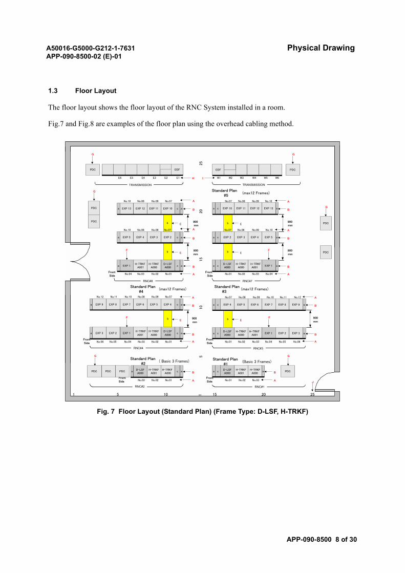
A50016-G5000-G212-1-7631 Physical DrawingAPP-090-8500-02 (E)-01
APP-090-8500 8 of 30
1.3 Floor Layout
The floor layout shows the floor layout of the RNC System installed in a room.
Fig.7 and Fig.8 are examples of the floor plan using the overhead cabling method.
Fig. 7 Floor Layout (Standard Plan) (Frame Type: D-LSF, H-TRKF)
25
20
15
10
5
1 5 10 1 15 20 25
a cD-LSFA000
H-TRKFA001
H-TRKFA000
a
No.03No.02No.01
a cD-LSFA000
H-TRKFA001
H-TRKFA000
a
No.03 No.02 No.01FrontSide A
B
Standard Plan#2
( Basic 3 Frames) Standard Plan#1
(Basic 3 Frames)
a cD-LSFA000
H-TRKFA000
H-TRKFA001
a
No.03No.02No.01
EXP 1 EXP 2 EXP 3
No.04 No.05 No.06
b
a c EXP 4 EXP 5 EXP 6 a
No.09No.08No.07
EXP 7 EXP 8 EXP 9
No.10 No.11 No.12 A
B
a cD-LSFA000
H-TRKFA000
H-TRKFA001
a
No.03 No.02 No.01
EXP 1EXP 2EXP 3
No.04No.05No.06
b
a cEXP 9 EXP 8 EXP 7 a
No.09No.08 No.07
EXP 6 EXP 5 EXP 4
No.10No.11No.12
E
FrontSide
A
B
900mm
900mm
Standard Plan#3
(max12 Frames)
E
A
B
A
B
A
B
acD-LSFA000
H-TRKFA000
H-TRKFA001
a EXP 1
b
aca
b
No.03No.02No.01
EXP 2 EXP 3
No.04
EXP 4 EXP 5
No.09No.08No.07 No.10
aca EXP 10 EXP 11 EXP 12 EXP 13
No.09No.08No.07 No.10
a cD-LSFA000
H-TRKFA000
H-TRKFA001
a
No.03 No.02 No.01
EXP 1
EXP 2EXP 3
No.04
b
a c aEXP 5 EXP 4
FrontSide
EXP 10EXP 11
b
a c a
No.09No.08 No.07
EXP 13 EXP 12
No.10
No.09No.08 No.07No.10
Standard Plan#5
(max12 Frames)
A
B
900mm
A
B
E
A
B
900mmE
E
E
A
B
900mm
A
B
A
B
900mm
FrontSide
FrontSide
FrontSide
Standard Plan#4
(max12 Frames)
PDC
PDC
PDCPDCPDCPDC
G G
FF
F F
ODF PDC
W1 W2 W3 W4 W5 W6I
ODFPDC
E1E2E3E4E5E6 H
G G
G
PDC
PDC
G
J
TRANSMISSION TRANSMISSION
RNC#7RNC#8
RNC#3RNC#4
RNC#1RNC#2
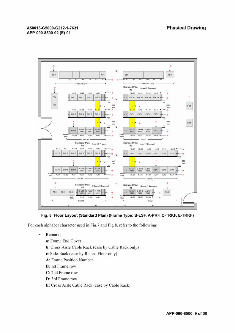
A50016-G5000-G212-1-7631 Physical DrawingAPP-090-8500-02 (E)-01
APP-090-8500 9 of 30
Fig. 8 Floor Layout (Standard Plan) (Frame Type: B-LSF, A-PRF, C-TRKF, E-TRKF)
For each alphabet character used in Fig.7 and Fig.8, refer to the following:
• Remarksa: Frame End Coverb: Cross Aisle Cable Rack (case by Cable Rack only)c: Side-Rack (case by Raised Floor only)A: Frame Position NumberB: 1st Frame rowC: 2nd Frame rowD: 3rd Frame rowE: Cross Aisle Cable Rack (case by Cable Rack)
25
20
15
10
5
1 5 10 1 15 20 25
a cB-LSFA000
C-TRKFA000
A-PRFA000
a
No.03No.02No.01
a cB-LSFA000
C-TRKFA000
A-PRFA000
a
No.03 No.02 No.01FrontSide A
B
Standard Plan#2
( Basic 3 Frames) Standard Plan#1
(Basic 3 Frames)
a cB-LSFA000
C-TRKFA000
A-PRFA000
a
No.03No.02No.01
EXP 1 EXP 2 EXP 3
No.04 No.05 No.06
b
a c EXP 4 EXP 5 EXP 6 a
No.09No.08No.07
EXP 7 EXP 8 EXP 9
No.10 No.11 No.12 A
B
a cB-LSFA000
C-TRKFA000
A-PRFA000
a
No.03 No.02 No.01
EXP 1EXP 2EXP 3
No.04No.05No.06
b
a cEXP 9 EXP 8 EXP 7 a
No.09No.08 No.07
EXP 6 EXP 5 EXP 4
No.10No.11No.12
E
FrontSide
A
B
900mm
900mm
Standard Plan#3
(max12 Frames)
E
A
B
A
B
A
B
acB-LSFA000
C-TRKFA000
A-PRFA000
a EXP 1
b
aca
b
No.03No.02No.01
EXP 2 EXP 3
No.04
EXP 4 EXP 5
No.09No.08No.07 No.10
aca EXP 10 EXP 11 EXP 12 EXP 13
No.09No.08No.07 No.10
a cB-LSFA000
C-TRKFA000
A-PRFA000
a
No.03 No.02 No.01
EXP 1
EXP 2EXP 3
No.04
b
a c aEXP 5 EXP 4
FrontSide
EXP 10EXP 11
b
a c a
No.09No.08 No.07
EXP 13 EXP 12
No.10
No.09No.08 No.07No.10
Standard Plan#5
(max12 Frames)
A
B
900mm
A
B
E
A
B
900mmE
E
E
A
B
900mm
A
B
A
B
900mm
FrontSide
FrontSide
FrontSide
Standard Plan#4
(max12 Frames)
PDC
PDC
PDCPDCPDCPDC
G G
FF
F F
ODF PDC
W1 W2 W3 W4 W5 W6I
ODFPDC
E1E2E3E4E5E6 H
G G
G
PDC
PDC
G
J
TRANSMISSION TRANSMISSION
RNC#7RNC#8
RNC#3RNC#4
RNC#1RNC#2

A50016-G5000-G212-1-7631 Physical DrawingAPP-090-8500-02 (E)-01
APP-090-8500 10 of 30
F: Attention! This equipment must be installed here.G: Power Distribution CubicleH: EastI: West
• Equipment NameRNC: Radio Network ControllerDSX(DDF): Digital Distribution FrameODF(FDF): Fiber Distribution Frame
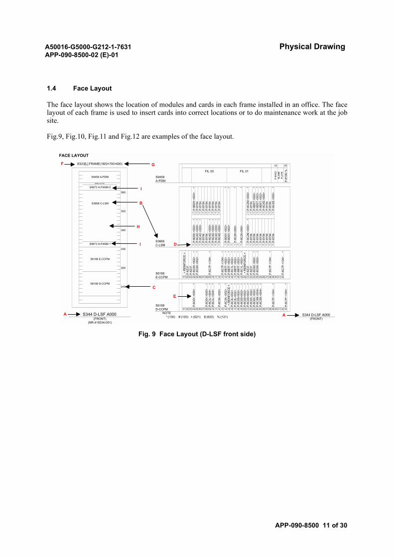
A50016-G5000-G212-1-7631 Physical DrawingAPP-090-8500-02 (E)-01
APP-090-8500 11 of 30
1.4 Face Layout
The face layout shows the location of modules and cards in each frame installed in an office. The facelayout of each frame is used to insert cards into correct locations or to do maintenance work at the jobsite.
Fig.9, Fig.10, Fig.11 and Fig.12 are examples of the face layout.
Fig. 9 Face Layout (D-LSF front side)
FACE LAYOUT
ES23[L] FRAME(1800×700×600)
S9458 A-PDM
FIL 00 FIL 01
S9458A-PDM
S9352 A-FTSU
S9673 A-FANM 0 *
P-8
Y94
P-8
Y94
P-8
D0V
<00
2>
095 105
* *
P-8
Y94
*
* * * *
P-8
C4D
<00
0>
060P
-8D
0H <
003>
P-8
Y94
P-8
Y94
235
*
P-8
D0T
<00
2>
* *
P-8
C2K
<000
>
P-8
C2M
<00
0>P
-8Y
94
P-8
Y94
P-8
Y94
P-8
Y94
P-8
Y94S3668 C-LSM
050025 035 045 245 255055 065 075 085 225
* * * * *
P-8
D0V
<00
2>
P-8
C2K
<000
>
195
P-8
D0T
<00
2>
P-8
C4D
<00
0>P
-8Y
94
P-8
D0H
<00
3>P
-8C
4D <
000>
P-8
C4D
<00
0>P
-8Y
94P
-8Y
94P
-8C
4D <
000>
P-8
C4D
<00
0>
P-8
Y94
P-8
Y94
P-8
Y94
P-8
C4D
<00
0>P
-8C
4D <
000>
P-8
C2M
<00
0>P
-8Y
94
040
P-8
Y94
075
S3668 P-8
Y94
P-8
Y94
P-8
Y94
035 045 055 065S9673 A-FANM 1 C-LSM 025 085 095 105 115 125 135 145 155 165 175 185 195 245 255205 215 225 235
S6188 E-CCPM
030
020
* * * * * * * * * * * * * *
= R
EIN
FOR
CE
=P
-8Z3
7P
-8Z3
7P
-8C
6X <
002>
P-8
C6X
<00
2>
P-8
C7P
<10
4>
P-8
C7P
<10
4>P
-8B
7F <
002>
P-8
B7F
<00
2>P
-8C
1L <
002>
P-8
B7F
<00
2>P
-8B
7F <
002>
P-8
C1L
<00
2> =
RE
INFO
RC
E =
P-8
Z37
P-8
Z37
P-8
C6X
<00
2>P
-8C
6X <
002>
P-8
C7P
<10
4>
P-8
C7P
<10
4>S6188 D-CCPM
S6188E-CCPM 01 02 03 04 05 06 07 08 09 10 11 12 13 14 15 16 17 18 19 20 21 22 23 24 25 26 27 28 29 30 31 32
* * * * * * * * * ** * * *
P-8
C6V
<00
0>
** *
P-8
C6V
<00
0>
010
S6188 P-8
C3J
<00
4>P
-8C
3J <
004>
P-8
C3A
<00
2>
P-8
C0S
<002
>
P-8
C6X
<00
2>
P-8
C3A
<00
2> =
RE
INFO
RC
E =
P-8
C0S
<002
>P
-8C
0S<0
02>
P-8
C3L
<002
>P
-8C
3L<0
02>
P-8
C0S
<002
>
P-8
C6X
<00
2>P
-8C
3M <
004>
04 05 06
P-8
C7P
<10
4>
07
P-8
C7P
<10
4>
P-8
C3M
<00
4>
D-CCPM 01 02 03 08 09 10 11 12 13 14 15 16 17 18 19 20 21 22 23 24 25 26 27 28 29 30 31 32 33
*
S344 D-LSF A000 NOTE S344 D-LSF A000(FRONT) (FRONT)
(NR-419334-001)
*:(130) #:(120) +:(621) $:(620) %:(121)
0502
P-8
Y0D
%
BLAN
KPL
ATE
P-8W
22
205 215
* * *
P-8
D0T
<00
2>
175 185
A A
B
H
I
C
I
GF
D
E
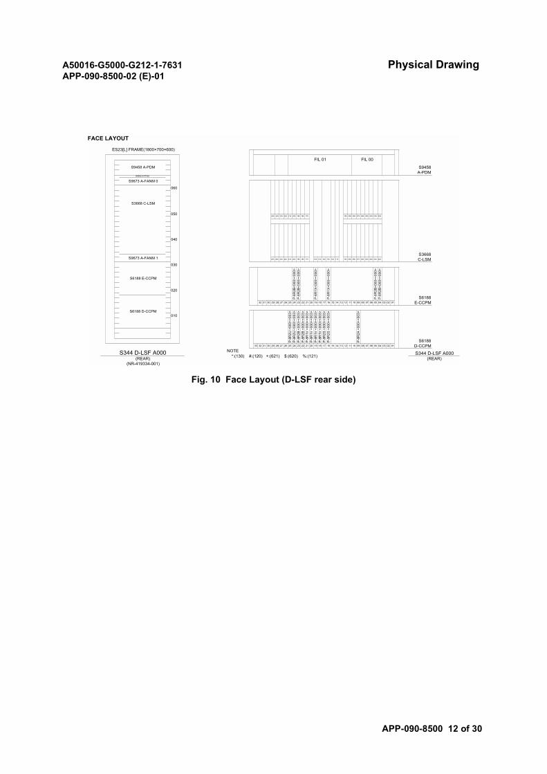
A50016-G5000-G212-1-7631 Physical DrawingAPP-090-8500-02 (E)-01
APP-090-8500 12 of 30
Fig. 10 Face Layout (D-LSF rear side)
FACE LAYOUT
ES23[L] FRAME(1800×700×600)
FIL 00
S9458 A-PDM S9458A-PDM
FIL 01
255 245 235
S9352 A-FTSU
S9673 A-FANM 0
060
185 175 105 095 045 035 025
S3668 C-LSM
050075 065 055225 215 205 195 085
040
S3668S9673 A-FANM 1 255 245 235 225 215 205 195 185 175 165 155 145 135 125 115 105 095 085 075 065 055 045 035 025 C-LSM
S6188 E-CCPM
030
P-8
R1X
<000
><00
0>
P-8
R1X
<000
><00
0>
P-8
R2B
<000
><00
0>P
-8R
2B<0
00><
000>
P-8
R2B
<000
><00
0>P
-8R
2B<0
00><
000>
020
S6188 D-CCPM
S618832 31 30 29 28 27 26 25 24 23 22 21 20 19 18 17 16 15 14 13 12 11 10 09 08 07 06 05 04 03 02 01 E-CCPM
33
P-8
R2U
<00
0><0
03>
P-8
R2U
<00
0><0
03>
P-8
R2B
<00
0><0
03>
P-8
R2B
<00
0><0
03>
P-8
R2S
<00
0><0
03>
P-8
R2S
<00
0><0
03>
P-8
R1V
<00
0><0
03>
P-8
R1V
<00
0><0
03>
P-8
R1V
<00
0><0
03>
P-8
R1V
<00
0><0
03>
P-8
R2A
<00
0><0
03>
010
S618832 31 30 29 28 27 26 25 24 23 22 21 20 19 18 17 10 0916 15 14 13
(REAR) (REAR)(NR-419334-001)
*:(130) #:(120) +:(621) $:(620) %:(121)
D-CCPM
S344 D-LSF A000 NOTE S344 D-LSF A000
08 07 06 0512 11 04 03 02 01
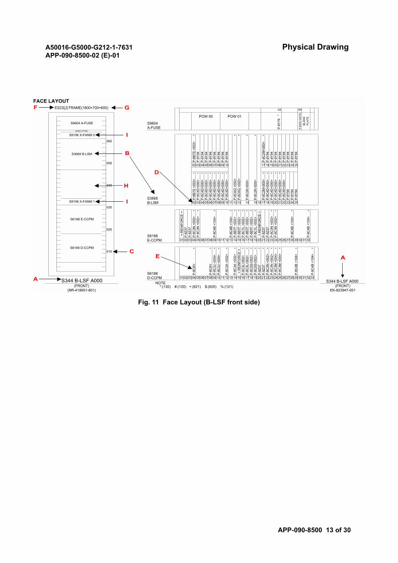
A50016-G5000-G212-1-7631 Physical DrawingAPP-090-8500-02 (E)-01
APP-090-8500 13 of 30
Fig. 11 Face Layout (B-LSF front side)
FACE LAYOUTES23[J] FRAME(1800×700×600)
S9604 A-FUSE
POW 00 POW 01
P-8
Y78
*
P-8
X44
<000
>%
BLA
NK
PLA
TE
02 05
S9604A-FUSE
S9352 A-FTSU
S9196 X-FANM 0 *
P-8
Y94
P-8
Y94
P-8
C6Q
<00
2>
09 10
*
* * * *
P-8
C2K
<000
>
P-8
C2M
<000
>P
-8Y
94
17 18
P-8
Y94
P-8
Y94
P-8
Y94
2324 25
060
P-8
B7S
<00
3>P
-8Y
94P
-8Y
94
*
P-8
Y94
P-8
Y94
P-8
Y94
P-8
Y94
P-8
Y94
P-8
Y94
P-8
Y94S3668 B-LSM
050 02 03 04 2021220506 0708
* * * * * * * * * * *
P-8
C6Q
<00
2>
P-8
C2K
<000
>
19
P-8
Y94
* * *
P-8
B7S
<00
3>P
-8C
4D<0
00>
P-8
C4D
<000
>P
-8C
4D<0
00>
P-8
C4D
<000
>P
-8C
4D<0
00>
P-8
C4D
<000
>
P-8
C4D
<000
>P
-8C
4D<0
00>
P-8
C4D
<000
>P
-8C
4D<0
00>
P-8
C2M
<000
>P
-8C
4D<0
00>
040
P-8
C4D
<000
>P
-8C
4D<0
00>
S3668 P-8
Y94
P-8
Y94
P-8
Y94
S9196 X-FANM 1 B-LSM 02 03 04 0506 070809 1011 1213 14 151617 1819 202122 2324 25
S6188 E-CCPM
030
020
* * * * * * * * * * * * * *
= R
EIN
FOR
CE
=P
-8Z3
7P
-8Z3
7P
-8C
3N <
002>
P-8
C3N
<00
2>
P-8
C4B
<10
4>
P-8
C4B
<10
4>P
-8B
7F <
002>
P-8
B7F
<00
2>P
-8C
1L <
002>
P-8
B7F
<00
2>P
-8B
7F <
002>
P-8
C1L
<00
2> =
RE
INFO
RC
E =
P-8
Z37
P-8
Z37
P-8
C3N
<00
2>P
-8C
3N <
002>
P-8
C4B
<10
4>
P-8
C4B
<10
4>
S6188 D-CCPM
S6188E-CCPM 0102 0304 05 06 0708 091011 1213 141516 1718 192021 2223 242526 2728 293031 32
* * * * * * * * * ** * * *
P-8
C6V
** *
P-8
C6V
010
S6188 P-8
C3J
<00
4>P
-8C
3J <
004>
P-8
C3A
<00
2>
P-8
C0S
<002
>
P-8
C3N
<00
2>
P-8
C3A
<00
2> =
RE
INFO
RC
E =
P-8
Z37
P-8
Z37
P-8
C3L
<002
>P
-8C
3L<0
02>
P-8
C0S
<002
>
P-8
C3N
<00
2>P
-8C
3M <
004>
04 05 06
P-8
C4B
<10
4>
07
P-8
C4B
<10
4>
P-8
C3M
<00
4>D-CCPM 0102 03 08 091011 1213 141516 1718 192021 2223 242526 2728 293031 3233
*
S344 B-LSF A000 NOTE S344 B-LSF A000*:(130) #:(120) +:(621) $:(620) %:(121)(FRONT) (FRONT)
(NR-418651-801) EK-823947-001
G
B
D
E
A
C
I
F
A
H
I
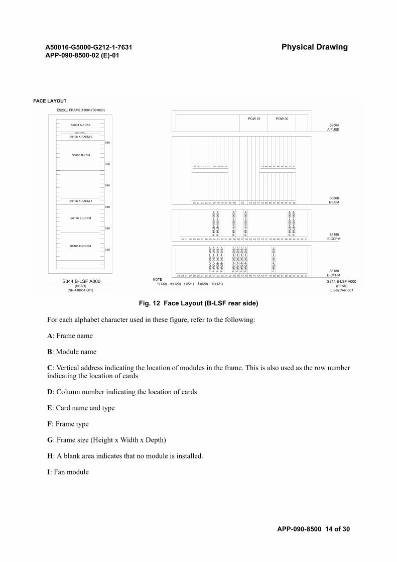
A50016-G5000-G212-1-7631 Physical DrawingAPP-090-8500-02 (E)-01
APP-090-8500 14 of 30
Fig. 12 Face Layout (B-LSF rear side)
For each alphabet character used in these figure, refer to the following:
A: Frame name
B: Module name
C: Vertical address indicating the location of modules in the frame. This is also used as the row numberindicating the location of cards
D: Column number indicating the location of cards
E: Card name and type
F: Frame type
G: Frame size (Height x Width x Depth)
H: A blank area indicates that no module is installed.
I: Fan module
FACE LAYOUT
ES23[J] FRAME(1800×700×600)
POW 01 POW 00
S9604 A-FUSE S9604A-FUSE
25 24 23
S9352 A-FTSU
S9196 X-FANM 0
060
18 17 10 09 04 03 02
S3668 B-LSM
05007 06 0522 21 20 19 08
040
S3668S9196 X-FANM 1
25 24 23 22 21 20 19 18 17 16 15 14 13 12 11 10 09 08 07 06 05 04 03 02 B-LSM
S6188 E-CCPM
030
P-8
R1X
<000
><00
3>
P-8
R1X
<000
><00
3>
P-8
R2B
<000
><00
0>P
-8R
2B<0
00><
000>
P-8
R2B
<000
><00
0>P
-8R
2B<0
00><
000>
020
S6188 D-CCPM
S618832 31 30 29 28 27 26 25 24 23 22 21 20 19 18 17 16 15 14 13 12 11 10 09 08 07 06 05 04 03 02 01 E-CCPM
33
P-8
R2U
<000
><00
3>P
-8R
2U<0
00><
003>
P-8
R2B
<000
><00
3>P
-8R
2B<0
00><
003>
P-8
R2S
<000
><00
3>P
-8R
2S<0
00><
003>
P-8
R1V
<000
><00
3>P
-8R
1V<0
00><
003>
P-8
R2A
<000
><00
3>010
S618832 31 30 29 28 27 26 25 24 23 22 21 20 19 18 17 16 15 14 13 12 11 10 09 08 07 06 05 04 03 02 01 D-CCPM
S344 B-LSF A000 NOTE S344 B-LSF A000*:(130) #:(120) +:(621) $:(620) %:(121)(REAR) (REAR)
(NR-418651-801) EK-823947-001
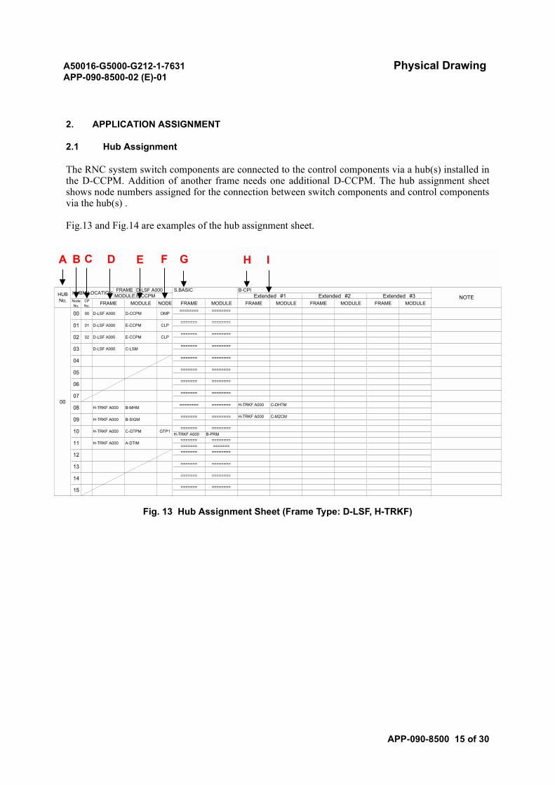
A50016-G5000-G212-1-7631 Physical DrawingAPP-090-8500-02 (E)-01
APP-090-8500 15 of 30
2. APPLICATION ASSIGNMENT
2.1 Hub Assignment
The RNC system switch components are connected to the control components via a hub(s) installed inthe D-CCPM. Addition of another frame needs one additional D-CCPM. The hub assignment sheetshows node numbers assigned for the connection between switch components and control componentsvia the hub(s) .
Fig.13 and Fig.14 are examples of the hub assignment sheet.
Fig. 13 Hub Assignment Sheet (Frame Type: D-LSF, H-TRKF)
NOTEB-CPIS.BASIC
========
======= ========
======= ========
======= ========
=============== ==============
H-TRKF A000 B-PRM======= ========
======= ======== H-TRKF A000 C-M2CM
======== ======== H-TRKF A000 C-DHTM
======= ========
======= ========
======= ========
======= ========
======= ========
======= ========
Extended #1FRAME MODULEFRAME MODULE
======== ========
HUBNo,
Extended #3FRAME MODULECP
No,NodeNo, FRAME MODULE
E-CCPM Extended #2FRAME
FRAMEMODULE
D-LSF A000HUBM LOCATION
MODULE NODE
00
00 00 D-LSF A000 D-CCPM OMP
02 02 D-LSF A000
01 01 D-LSF A000 E-CCPM CLP
E-CCPM CLP======= ========
03 D-LSF A000 C-LSM
04
05
06
07
08 H-TRKF A000 B-MHM
09 H-TRKF A000 B-SIGM
10 H-TRKF A000 C-GTPM GTP1
11 H-TRKF A000 A-DTIM
12
13
14=======15
A B C D E F G H I
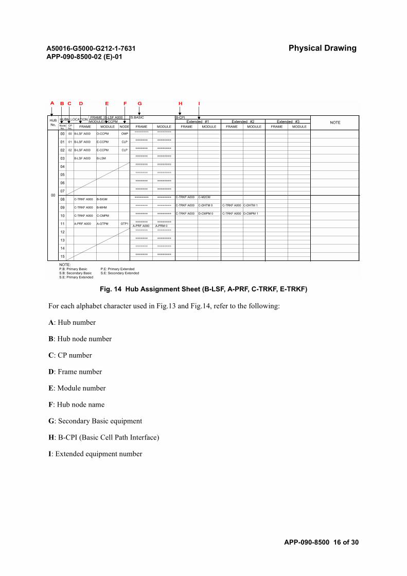
A50016-G5000-G212-1-7631 Physical DrawingAPP-090-8500-02 (E)-01
APP-090-8500 16 of 30
Fig. 14 Hub Assignment Sheet (B-LSF, A-PRF, C-TRKF, E-TRKF)
For each alphabet character used in Fig.13 and Fig.14, refer to the following:
A: Hub number
B: Hub node number
C: CP number
D: Frame number
E: Module number
F: Hub node name
G: Secondary Basic equipment
H: B-CPI (Basic Cell Path Interface)
I: Extended equipment number
NOTE:P.B: Primary Basic P.E: Primary Extended
NOTEB-CPIS.BASIC
========
======= ========
======= ========
======= ========
========A-PRF A000 A-PRM 0
=======
======= ======== C-TRKF A000 D-CMPM 0
======= ======== C-TRKF A000 C-DHTM 0
======== ======== C-TRKF A000 C-M2CM
======= ========
======= ========
======= ========
======= ========
======= ========
======= ========
Extended #1FRAME MODULEFRAME MODULE
======== ========
HUBNo,
Extended #3FRAME MODULECP
No,NodeNo, FRAME MODULE
E-CCPM Extended #2FRAME
FRAMEMODULE
B-LSF A000HUBM LOCATION
MODULE NODE
00
00 00 B-LSF A000 D-CCPM OMP
02 02 B-LSF A000
01 01 B-LSF A000 E-CCPM CLP
E-CCPM CLP======= ========
03 B-LSF A000 B-LSM
04
05
06
07
08 C-TRKF A000 B-SIGM
09 C-TRKF A000 B-MHMC-TRKF A000 C-DHTM 1
10 C-TRKF A000 C-CMPMC-TRKF A000 D-CMPM 1
11 A-PRF A000 A-GTPM GTP1
12
13
14=======15
S.B: Secondary Basic S.E: Secondary ExtendedS.E: Primary Extended
A B C D E F G H I
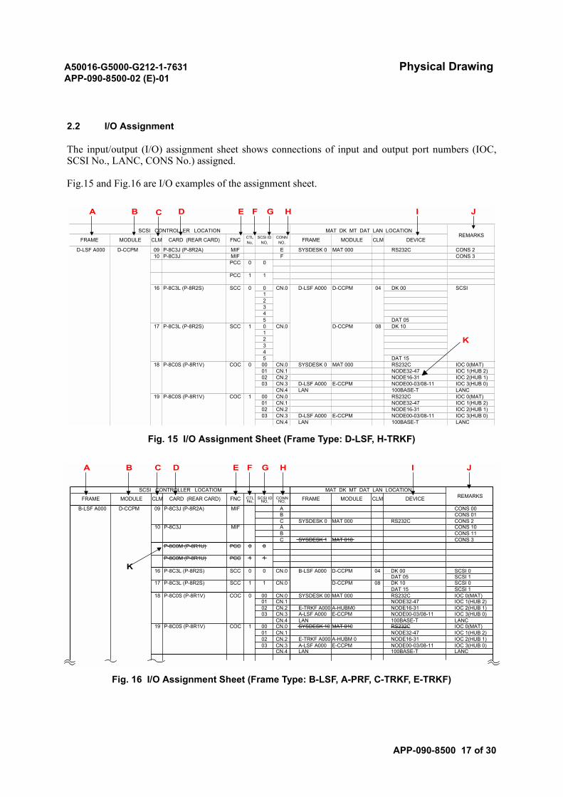
A50016-G5000-G212-1-7631 Physical DrawingAPP-090-8500-02 (E)-01
APP-090-8500 17 of 30
2.2 I/O Assignment
The input/output (I/O) assignment sheet shows connections of input and output port numbers (IOC,SCSI No., LANC, CONS No.) assigned.
Fig.15 and Fig.16 are I/O examples of the assignment sheet.
Fig. 15 I/O Assignment Sheet (Frame Type: D-LSF, H-TRKF)
Fig. 16 I/O Assignment Sheet (Frame Type: B-LSF, A-PRF, C-TRKF, E-TRKF)
1234
1234
PCC
CONS 3CONS 2
10 P-8C3J MIF FSYSDESK 0 MAT 000 RS232CMIF E
SCC 0 016 P-8C3L (P-8R2S)
1 1
DAT 15
PCC 0 0
08 DK 10
5
100BASE-T LANCCN.4 LANNODE00-03/08-11 IOC 3(HUB 0)
CN.0 D-LSF A000 D-CCPM 04 DK 00
03 CN.3 D-LSF A000 E-CCPMNODE16-31 IOC 2(HUB 1)
SCSI
17 P-8C3L (P-8R2S)
02 CN.2NODE32-47 IOC 1(HUB 2)
SCC 15
01 CN.1RS232C IOC 0(MAT)
DAT 050
00 CN.019 P-8C0S (P-8R1V) COC 1100BASE-T LANC
CN.0 D-CCPM
E-CCPM NODE00-03/08-11 IOC 3(HUB 0)IOC 2(HUB 1)
CN.4 LAN03 CN.3 D-LSF A000
NODE16-3102 CN.2
18 P-8C0S (P-8R1V)NODE32-47 IOC 1(HUB 2)
IOC 0(MAT)01 CN.1
SYSDESK 0 MAT 000 RS232C
CLM DEVICE
D-LSF A000 D-CCPM
SCSI IDNO,
CONNNO, FRAME MODULE
09 P-8C3J (P-8R2A)
COC 0 00 CN.0
SCSI CONTROLLER LOCATION MAT DK MT DAT LAN LOCATIONREMARKS
FRAME MODULE CLM CARD (REAR CARD) FNC CTLNo,
A B D E F G H I JC
K
CONS 3MAT 010B CONS 11C SYSDESK 1
P-8C0M (P-8R1U)
P-8C0M (P-8R1U)
CONS 10CONS 2
10 P-8C3J MIF ASYSDESK 0 MAT 000 RS232CC
CONS 01CONS 00
BMIF A
PCC 1 1
DAT 15 SCSI 1
PCC 0 0
08 DK 10 SCSI 0
100BASE-T LANC
16 P-8C3L (P-8R2S) SCC 0 0
CN.4 LANNODE00-03/08-11 IOC 3(HUB 0)
CN.0 B-LSF A000 D-CCPM 04 DK 00
03 CN.3 A-LSF A000 E-CCPMNODE16-31 IOC 2(HUB 1)
SCSI 0
17 P-8C3L (P-8R2S)
02 CN.2 E-TRKF A000 A-HUBM 0NODE32-47 IOC 1(HUB 2)
SCC 1
01 CN.1RS232C IOC 0(MAT)
DAT 05 SCSI 11
00 CN.0 SYSDESK 10 MAT 01019 P-8C0S (P-8R1V) COC 1100BASE-T LANC
CN.0 D-CCPM
CN.4 LANE-CCPM NODE00-03/08-11 IOC 3(HUB 0)
IOC 2(HUB 1)03 CN.3 A-LSF A000
E-TRKF A000 A-HUBM0 NODE16-3102 CN.2
18 P-8C0S (P-8R1V)NODE32-47 IOC 1(HUB 2)
IOC 0(MAT)01 CN.1
SYSDESK 00 MAT 000 RS232C
CLM DEVICE
B-LSF A000 D-CCPM
SCSI IDNO,
CONNNO, FRAME MODULE
09 P-8C3J (P-8R2A)
COC 0 00 CN.0
SCSI CONTROLLER LOCATIOM MAT DK MT DAT LAN LOCATIONREMARKSFRAME MODULE CLM CARD (REAR CARD) FNC CTL
No,
A B C D E F G H I J
K

A50016-G5000-G212-1-7631 Physical DrawingAPP-090-8500-02 (E)-01
APP-090-8500 18 of 30
For each alphabet character used in Fig.15 and Fig.16, refer to the following:
A: Frame name
B: Module name
C: Location (column number) of cards in a module
D: Card name
E: Function name
F: Control number
G: SCSI ID number
H: Connector address
I: Device name
J: Remarks
K: Not assigned.
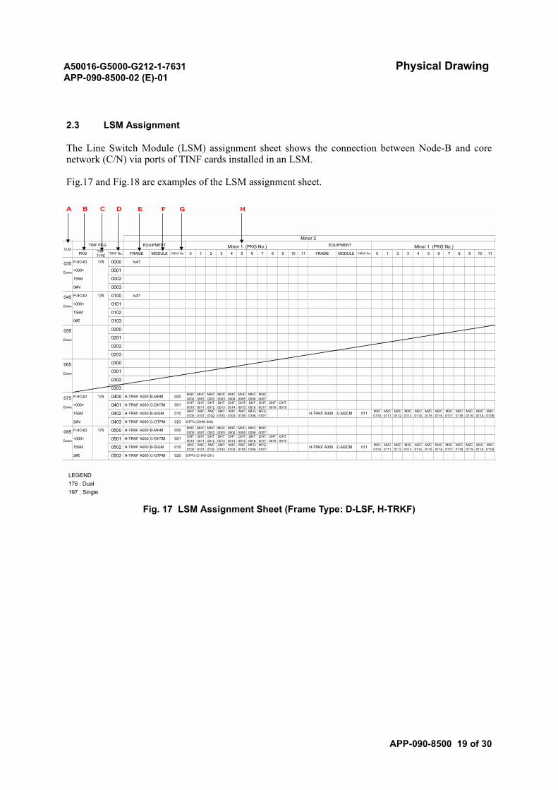
A50016-G5000-G212-1-7631 Physical DrawingAPP-090-8500-02 (E)-01
APP-090-8500 19 of 30
2.3 LSM Assignment
The Line Switch Module (LSM) assignment sheet shows the connection between Node-B and corenetwork (C/N) via ports of TINF cards installed in an LSM.
Fig.17 and Fig.18 are examples of the LSM assignment sheet.
Fig. 17 LSM Assignment Sheet (Frame Type: D-LSF, H-TRKF)
A B C D E F HG
LEGEND176 : Dual197 : Single
8 9
TINF PKG
MODULE
0000
0001
P-8C4D
<000>
EQUIPMENT
CMUX No.
156M
0#N
FRAME 0
0002
0003
M2C0111
M2C0112
M2C0113011H-TRKF A000 C-M2CM
DownDHT0014001
156M 0502 H-TRKF A000 B-SIGM ANC0103
ANC0102
2#E 0503 H-TRKF A000
ANC0100
MFG0106
0403 H-TRKF A000 C-GTPM 020MHC0000
MHC0001
ANC0105
085 000P-8C4D 176 0500 H-TRKF A000 B-MHM
ANC0101
ANC0104
DHT0018
DHT0013
DHT0015
MHC0007DHT0017
MHC0006
010
DHT0019
M2C0115
M2C0116
M2C0114
M2C0119
M2C0118
ANC0100
ANC0101
ANC0102
2#N GTP0 (CIHW 000)
0402 M2C0111
M2C0112
M2C0113
M2C0114
M2C0115
M2C0116
075 000B-MHM
0303
DHT0013
DHT0016
DHT0015
DHT0017
DHT0019
ANC0104010
DHT0011Down
H-TRKF A000156M
DHT0014
B-SIGM
DHT0012
Down 0301
0302
C-M2CMH-TRKF A000
065
0203
Down
055
Iu#1
M2C0110
045 P-8C4D 176 0100
<000> 0101
Down
0202
M2C0110
Down
Iu#1
TINF No.TINFTYPE
035 176
1 2CLM
PKG
EQUIPMENT
FRAME9 10 11
Minor 1 (PKG No.)5 6 7 83 4
156M 0102
0#E 0103
0200
MHC0000
DHT0016
ANC0105
MFG0106
0300
0201
C-DHTM DHT0010
001
C-GTPM 020 GTP0 (C1HW 001)
MFG0107
MFG0107
ANC0103
<000> C-DHTM DHT0010
DHT0011
DHT00120501 H-TRKF A000
H-TRKF A000
<000> 0401 H-TRKF A000
P-8C4D 176 0400
MODULE CMUX No.
Minor 1 (PKG No.)0 1 2 3 4 5 6 7 10 11
M2C0117
M2C0119
M2C0118
M2C011A
M2C011B
M2C0117
M2C011A
M2C011B
Minor 2
MHC0001
MHC0002
MHC0003
MHC0004
MHC0005
MHC0006
MHC0007
MHC0002
MHC0003
MHC0004
MHC0005
DHT0018
011
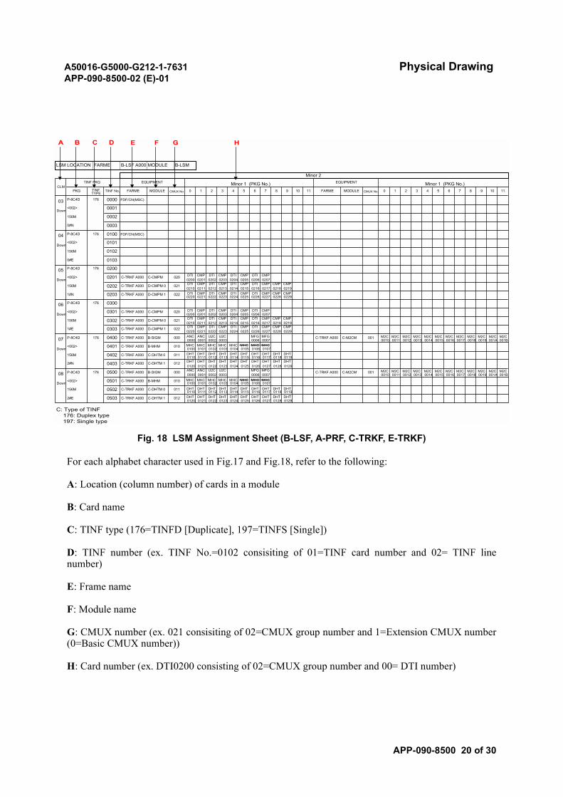
A50016-G5000-G212-1-7631 Physical DrawingAPP-090-8500-02 (E)-01
APP-090-8500 20 of 30
Fig. 18 LSM Assignment Sheet (B-LSF, A-PRF, C-TRKF, E-TRKF)
For each alphabet character used in Fig.17 and Fig.18, refer to the following:
A: Location (column number) of cards in a module
B: Card name
C: TINF type (176=TINFD [Duplicate], 197=TINFS [Single])
D: TINF number (ex. TINF No.=0102 consisiting of 01=TINF card number and 02= TINF linenumber)
E: Frame name
F: Module name
G: CMUX number (ex. 021 consisiting of 02=CMUX group number and 1=Extension CMUX number(0=Basic CMUX number))
H: Card number (ex. DTI0200 consisting of 02=CMUX group number and 00= DTI number)
Minor 2
00190015 0016 0017 0018 001A 001B00140010 0011 0012 0013
001A 001B0016 0017 0018 00190012 0013 0014 0015
10 11
Minor 1 (PKG No.)0 1 2 3 4 5 6 7
C-TRKF A000 C-M2CM 001
MODULE CMUX No.
2#E 0503 C-TRKF A000 C-DHTM 10120 0121 0122 0123
MHC0103
MHC0105
MHC0106
DHT0114
DHT0115
DHT0116
MHC0107
B-MHM MHC0100
MHC0101
MHC0102
<002> 0501 C-TRKF A000
U2C0003
MFG0006
MFG0007
B-SIGM ANC0000
ANC0001
U2C0002
P-8C4D 176 0500 C-TRKF A000
DHT0123
DHT0125
DHT0126
DHT0127
C-DHTM 1 DHT0120
DHT0121
DHT0122
2#N 0403 C-TRKF A000
0113 0115 0116 0117C-DHTM 0
0110 0111 0112156M 0402 C-TRKF A000
010 MHC0102
MHC0103
MHC0106
MHC0107
<002> 0401 C-TRKF A000 B-MHM MHC0100
MHC0101
P-8C4D 176 0400 C-TRKF A000 B-SIGM ANC0000
ANC0001
U2C0002
U2C0003
CMP0223
CMP0225
DTI0226MFG0006
CMP0227
1#E 0303 C-TRKF A000 D-CMPM 1 DTI0220
CMP0221
DTI0222
CMP0203
CMP0205
DTI0206
CMP0207
C-CMPM DTI0200
CMP0201
DTI0202
<002> 0301 C-TRKF A000
P-8C4D 176 03000223 0225 0226 0227
D-CMPM 10220 0221 0222
1#N 0203 C-TRKF A000
CMP0213
CMP0215
DTI0216
CMP0217
D-CMPM 0 DTI0210
CMP0211
DTI0212
021156M 0202 C-TRKF A000
CMP0203
CMP0205
DTI0206
CMP0207
<002> 0201 C-TRKF A000 C-CMPM DTI0200
CMP0201
DTI0202
P-8C4D 176 0200
0#E 0103
156M 0102
<002> 0101
P-8C4D 176 0100 FDF/CN(MSC)
EQUIPMENT
FARME9 10 11
Minor 1 (PKG No.)5 6 7 83 4
CLM
LSM LOCATION FARME B-LSF A000 MODULE B-LSM
PKG TINF No,TINFTYPE
03 176 FDF/CN(MSC)
CMP0219
CMP0215
DTI0216
Down
CMP0218
Down020
D-CMPM 0
DTI0214
DTI0210
CMP0211
DTI0212
CMP0213
DTI0214
04
Down
05DTI0204
0224022
06
0228 0229
DownDTI0204
020
156M 0302 C-TRKF A000 021 CMP0217
CMP0218
CMP0219
022
07 0000011
DownMHC0105
DTI0224
CMP0228
CMP0229
0010MHC0104
MFG0007
0114011
DHT0124
DHT0128
DHT0129
012
0118 0119
08 000
C-DHTM 0 DHT0110
DHT0111
DHT0112
DHT0113
C-TRKF A000 C-M2CM 001
0502 C-TRKF A000
DownMHC0104
010
156M DHT0117
DHT0118
DHT0119
011
0120124 0125 0126 0127 0128 0129
156M
0#N
FARME 0
0002
0003
TINF PKG
MODULE
0000
0001
P-8C4D
<002>
EQUIPMENT
CMUX No. 8 91 2
A B C D E F HG
M2C M2CM2C M2C M2C M2CM2C M2C M2C M2CM2CM2C
M2CM2C M2C M2C M2C M2C M2CM2CM2C M2C M2C M2C
DHT DHT DHT DHT DHT DHT DHT DHT DHT DHT
CMP CMP DTI CMPDTI CMP DTI DTI CMP CMP
DHT DHT DHT DHTDHT DHT DHT DHT DHT DHT
C: Type of TINF 176: Duplex type 197: Single type
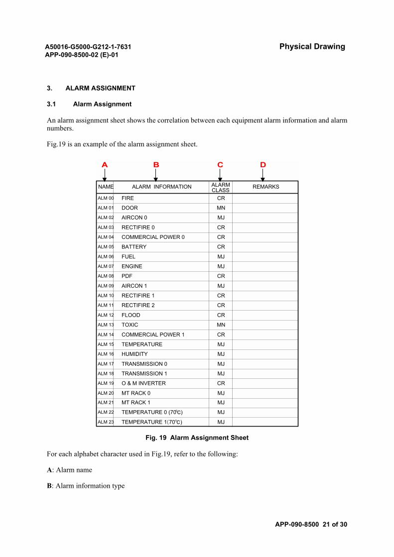
A50016-G5000-G212-1-7631 Physical DrawingAPP-090-8500-02 (E)-01
APP-090-8500 21 of 30
3. ALARM ASSIGNMENT
3.1 Alarm Assignment
An alarm assignment sheet shows the correlation between each equipment alarm information and alarmnumbers.
Fig.19 is an example of the alarm assignment sheet.
Fig. 19 Alarm Assignment Sheet
For each alphabet character used in Fig.19, refer to the following:
A: Alarm name
B: Alarm information type
ALARM INFORMATION REMARKS
FIRE CR
DOOR MN
AIRCON 0 MJ
RECTIFIRE 0 CR
COMMERCIAL POWER 0 CR
BATTERY CR
FUEL MJ
ENGINE MJ
PDF CR
AIRCON 1 MJ
RECTIFIRE 1 CR
RECTIFIRE 2 CR
FLOOD CR
TOXIC MN
COMMERCIAL POWER 1 CR
TEMPERATURE MJ
HUMIDITY MJ
TRANSMISSION 0 MJ
TRANSMISSION 1 MJ
O & M INVERTER CR
MT RACK 0 MJ
MT RACK 1 MJ
TEMPERATURE 0 (70℃) MJ
TEMPERATURE 1(70℃) MJ
A B C D
NAME
ALM 00
ALM 01
ALM 02
ALM 03
ALM 04
ALM 05
ALM 06
ALM 07
ALM 08
ALM 09
ALM 10
ALM 11
ALM 12
ALM 13
ALM 14
ALM 15
ALM 16
ALM 17
ALM 18
ALM 19
ALM 20
ALM 21
ALM 22
ALM 23
ALARMCLASS
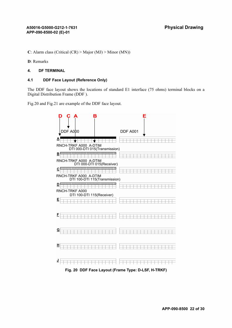
A50016-G5000-G212-1-7631 Physical DrawingAPP-090-8500-02 (E)-01
APP-090-8500 22 of 30
C: Alarm class (Critical (CR) > Major (MJ) > Minor (MN))
D: Remarks
4. DF TERMINAL
4.1 DDF Face Layout (Reference Only)
The DDF face layout shows the locations of standard E1 interface (75 ohms) terminal blocks on aDigital Distribution Frame (DDF ).
Fig.20 and Fig.21 are example of the DDF face layout.
Fig. 20 DDF Face Layout (Frame Type: D-LSF, H-TRKF)
A
B
DTI 100-DTI 115(Receiver)
J
E
F
G
C
D
H
RNCH-TRKF A000 A-DTIMDTI 100-DTI 115(Transmission)
RNCH-TRKF A000
RNCH-TRKF A000 A-DTIMDTI 000-DTI 015(Receiver)
DDF A000
RNCH-TRKF A000 A-DTIMDTI 000-DTI 015(Transmission)
DDF A001
D C A B E
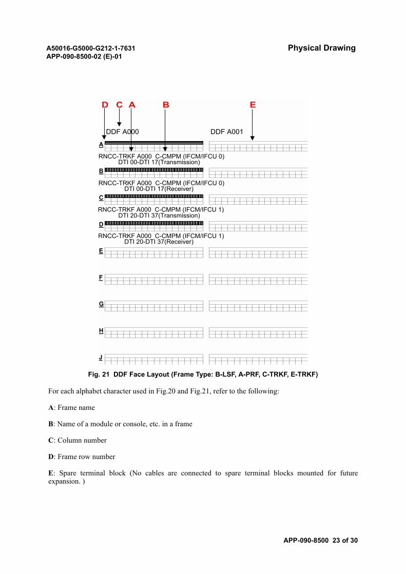
A50016-G5000-G212-1-7631 Physical DrawingAPP-090-8500-02 (E)-01
APP-090-8500 23 of 30
Fig. 21 DDF Face Layout (Frame Type: B-LSF, A-PRF, C-TRKF, E-TRKF)
For each alphabet character used in Fig.20 and Fig.21, refer to the following:
A: Frame name
B: Name of a module or console, etc. in a frame
C: Column number
D: Frame row number
E: Spare terminal block (No cables are connected to spare terminal blocks mounted for futureexpansion. )
A
B
DTI 20-DTI 37(Receiver)
J
E
F
G
C
D
H
RNCC-TRKF A000 C-CMPM (IFCM/IFCU 1)DTI 20-DTI 37(Transmission)
RNCC-TRKF A000 C-CMPM (IFCM/IFCU 1)
RNCC-TRKF A000 C-CMPM (IFCM/IFCU 0)DTI 00-DTI 17(Receiver)
DDF A000
RNCC-TRKF A000 C-CMPM (IFCM/IFCU 0)DTI 00-DTI 17(Transmission)
DDF A001
D C A B E
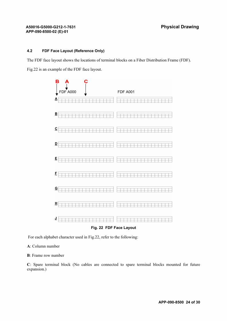
A50016-G5000-G212-1-7631 Physical DrawingAPP-090-8500-02 (E)-01
APP-090-8500 24 of 30
4.2 FDF Face Layout (Reference Only)
The FDF face layout shows the locations of terminal blocks on a Fiber Distribution Frame (FDF).
Fig.22 is an example of the FDF face layout.
Fig. 22 FDF Face Layout
For each alphabet character used in Fig.22, refer to the following:
A: Column number
B: Frame row number
C: Spare terminal block (No cables are connected to spare terminal blocks mounted for futureexpansion.)
FDF A001FDF A000
J
E
F
G
C
D
H
A
B
B A C
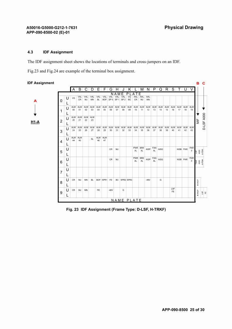
A50016-G5000-G212-1-7631 Physical DrawingAPP-090-8500-02 (E)-01
APP-090-8500 25 of 30
4.3 IDF Assignment
The IDF assignment sheet shows the locations of terminals and cross-jumpers on an IDF.
Fig.23 and Fig.24 are example of the terminal box assignment.
Fig. 23 IDF Assignment (Frame Type: D-LSF, H-TRKF)
IDF Assignment
H1-A
A
B C
G HA B C D T U VN P Q R
VALBL
VALBOF
VALSP 0
SJ K L ME F
VG VALCR
VALMJ
VALMN
VALSP 1
VALSP 2
VGBC
AALCR
AALMJ
AALMN
ALM00
ALM01
ALM02
ALM03
ALM04
ALM05
ALM06
ALM07
ALM08
ALM09
ALM15
ALM16
ALM17
ALM10
ALM11
ALM12
ALM13
ALM18
ALM19
ALM20
ALM21
ALM22
ALM23
ALM14
ALM24
ALM25
ALM26
ALM27
ALM28
ALM29
ALM30
ALM31
ALM32
ALM33
ALM34
ALM40
ALM41
ALM42
ALM35
ALM36
ALM37
ALM38
ALM43
ALM44
ALM45
SL ALM46
ALM47
ALM39
5U CR MJ PWR
AL
6
PAR0
AISB PARBRKAL
AISP FANAL
AISG
U CR MJ PWRAL
BRKAL
AISP FANAL
AISG PAR0
AISB PAR
7LU
FECR MJ MN BL -48V G
FE
BC SPR2 SPR3BOF SPR1
CR MJ MN -48V G LSFFE
UL
L
L
U
U
U
U
1L
2L
3L
4L
8L
9L
U
U
B-V
ALP
B-A
ALP
LSF
MIF
D-L
SF
A00
0N A M E P L A T E
FE
LSF
A00
0
A-P
DM
TRK
F
A00
0
A-P
DM
N A M E P L A T E
0
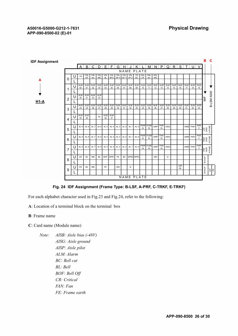
A50016-G5000-G212-1-7631 Physical DrawingAPP-090-8500-02 (E)-01
APP-090-8500 26 of 30
Fig. 24 IDF Assignment (Frame Type: B-LSF, A-PRF, C-TRKF, E-TRKF)
For each alphabet character used in Fig.23 and Fig.24, refer to the following:
A: Location of a terminal block on the terminal box
B: Frame name
C: Card name (Module name)
Note: AISB: Aisle bias (-48V)AISG: Aisle groundAISP: Aisle pilotALM: AlarmBC: Bell cutBL: BellBOF: Bell OffCR: CriticalFAN: FanFE: Frame earth
G HIDF Assignment
A B C D T U VN P Q R
VALBL
VALBFO
VALSP 0
SJ K L ME F
VG VALCR
VALMJ
VALMN
VALSP 1
VALSP 2
VGBC
AALCR
AALMJ
AALMN
ALM00
ALM01
ALM02
ALM03
ALM04
ALM05
ALM06
ALM07
ALM08
ALM09
ALM15
ALM16
ALM17
ALM10
ALM11
ALM12
ALM13
ALM18
ALM19
H1-A
ALM20
ALM21
ALM22
ALM23
ALM14
ALM24
ALM25
ALM26
ALM27
ALM28
ALM29
ALM30
ALM31
ALM32
ALM33
ALM34
ALM40
ALM41
ALM42
ALM35
ALM36
ALM37
ALM38
ALM43
ALM44
ALM45
SL ALM46
ALM47
ALM39
5AL 9 AL 8 AL 7U AL 6 AL 5 AL 4 AL 3 AL 2 AL 1 AL 0 PWR
AL
6
PAR0
AISB PARFUSEAL
AISP FANAL
AISG
AL 9 AL 8 AL 7U AL 6 AL 5 AL 4 AL 3 AL 2 AL 1 AL 0 PWRAL
FUSEAL
AISP FANAL
AISG PAR0
AISB PAR
AL 9 AL 8 AL 7
7 LU AL 6 AL 5 AL 4 AL 3 AL 2 AL 1 AL 0 PWR
AL
FE
PAR0
AISB PARFUSEAL
AISP FANAL
AISG
CR MJ MN BL -48V G
FE
BC SPR2 SPR3BOF SPR1
CR MJ MN -48V G LSFFE
UL
L
L
U
U
U
U
1 L
2 L
3 L
4 L
8 L
9 L
U
U
B-V
ALP
B-A
ALP
LSF
A-F
US
E
PR
FA
000
A-F
US
E
N A M E P L A T E
MIF
B-L
SM
A00
0
N A M E P L A T E
FE
LSF
A00
0A
-FU
SE
TRK
FA
000
0A
B C

A50016-G5000-G212-1-7631 Physical DrawingAPP-090-8500-02 (E)-01
APP-090-8500 27 of 30
FUSE: FuseG: GroundINV: InverterMJ: MajorMN: MinorPA: Power alarmPAR: Power resetPWR: PowerSL: Shield earthSP: SpareSPR: SpareVAL: Visual alarmVGBC: Visual ground bell cut
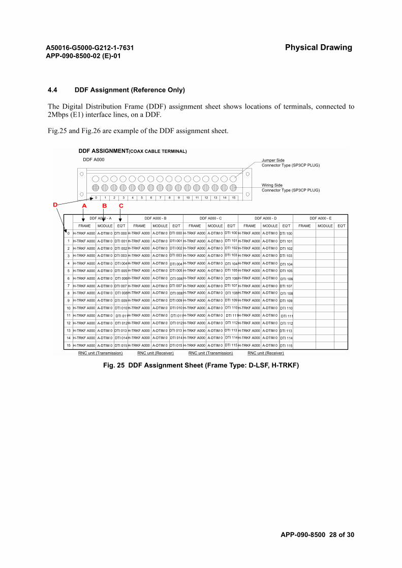
A50016-G5000-G212-1-7631 Physical DrawingAPP-090-8500-02 (E)-01
APP-090-8500 28 of 30
4.4 DDF Assignment (Reference Only)
The Digital Distribution Frame (DDF) assignment sheet shows locations of terminals, connected to2Mbps (E1) interface lines, on a DDF.
Fig.25 and Fig.26 are example of the DDF assignment sheet.
Fig. 25 DDF Assignment Sheet (Frame Type: D-LSF, H-TRKF)
14 1510 11 12 13
Wiring SideConnector Type (SP3CP PLUG)
0 1 2 3 4 5 6 7
DDF A000 Jumper SideConnector Type (SP3CP PLUG)
RNC unit (Transmission) RNC unit (Receiver) RNC unit (Transmission) RNC unit (Receiver)
MODULEMODULE EQ'T FRAMEFRAMEFRAME MODULE
DDF A000 - E
EQ'T
DDF A000 - D
15
14
13
12
11
6
5
4
FRAME
0 H-TRKF A000
MODULE
A-DTIM 0
DDF A000 - A
EQ'T
DTI 000
1
3
2
8
DDF A000 - B
EQ'T
9
8
7
10
9
DDF ASSIGNMENT(COAX CABLE TERMINAL)
DDF A000 - C
FRAME MODULE EQ'T
A B CD
H-TRKF A000 A-DTIM 0 H-TRKF A000 A-DTIM 0 H-TRKF A000 A-DTIM 0
H-TRKF A000 A-DTIM 0 DTI 001 H-TRKF A000 A-DTIM 0 H-TRKF A000 A-DTIM 0 H-TRKF A000 A-DTIM 0
H-TRKF A000 A-DTIM 0 DTI 002 H-TRKF A000 A-DTIM 0 H-TRKF A000 A-DTIM 0 H-TRKF A000 A-DTIM 0
H-TRKF A000 A-DTIM 0 DTI 003 H-TRKF A000 A-DTIM 0 H-TRKF A000 A-DTIM 0 H-TRKF A000 A-DTIM 0
H-TRKF A000 A-DTIM 0 DTI 004H-TRKF A000 A-DTIM 0 H-TRKF A000 A-DTIM 0 H-TRKF A000 A-DTIM 0
H-TRKF A000 A-DTIM 0 DTI 005 H-TRKF A000 A-DTIM 0 H-TRKF A000 A-DTIM 0 H-TRKF A000 A-DTIM 0
H-TRKF A000 A-DTIM 0 DTI 006H-TRKF A000 A-DTIM 0 H-TRKF A000 A-DTIM 0 H-TRKF A000 A-DTIM 0
H-TRKF A000 A-DTIM 0 DTI 007 H-TRKF A000 A-DTIM 0 H-TRKF A000 A-DTIM 0 H-TRKF A000 A-DTIM 0
H-TRKF A000 A-DTIM 0 DTI 008H-TRKF A000 A-DTIM 0 H-TRKF A000 A-DTIM 0 H-TRKF A000 A-DTIM 0
H-TRKF A000 A-DTIM 0 DTI 009 H-TRKF A000 A-DTIM 0 H-TRKF A000 A-DTIM 0 H-TRKF A000 A-DTIM 0
H-TRKF A000 A-DTIM 0 DTI 010 H-TRKF A000 A-DTIM 0 H-TRKF A000 A-DTIM 0 H-TRKF A000 A-DTIM 0
H-TRKF A000 A-DTIM 0 DTI 011H-TRKF A000 A-DTIM 0 H-TRKF A000 A-DTIM 0 H-TRKF A000 A-DTIM 0
H-TRKF A000 A-DTIM 0 DTI 012H-TRKF A000 A-DTIM 0 H-TRKF A000 A-DTIM 0 H-TRKF A000 A-DTIM 0
H-TRKF A000 A-DTIM 0 DTI 013 H-TRKF A000 A-DTIM 0 H-TRKF A000 A-DTIM 0 H-TRKF A000 A-DTIM 0
H-TRKF A000 A-DTIM 0 DTI 014H-TRKF A000 A-DTIM 0 H-TRKF A000 A-DTIM 0 H-TRKF A000 A-DTIM 0
H-TRKF A000 A-DTIM 0 DTI 015 H-TRKF A000 A-DTIM 0 H-TRKF A000 A-DTIM 0 H-TRKF A000 A-DTIM 0
DTI 000
DTI 001
DTI 002
DTI 003
DTI 005
DTI 007
DTI 004
DTI 006
DTI 008
DTI 009
DTI 010
DTI 011
DTI 012
DTI 013
DTI 014
DTI 015
DTI 100
DTI 101
DTI 102
DTI 103
DTI 105
DTI 107
DTI 104
DTI 106
DTI 108
DTI 109
DTI 110
DTI 111
DTI 112
DTI 113
DTI 114
DTI 115
DTI 100
DTI 101
DTI 102
DTI 103
DTI 105
DTI 107
DTI 104
DTI 106
DTI 108
DTI 109
DTI 110
DTI 111
DTI 112
DTI 113
DTI 114
DTI 115
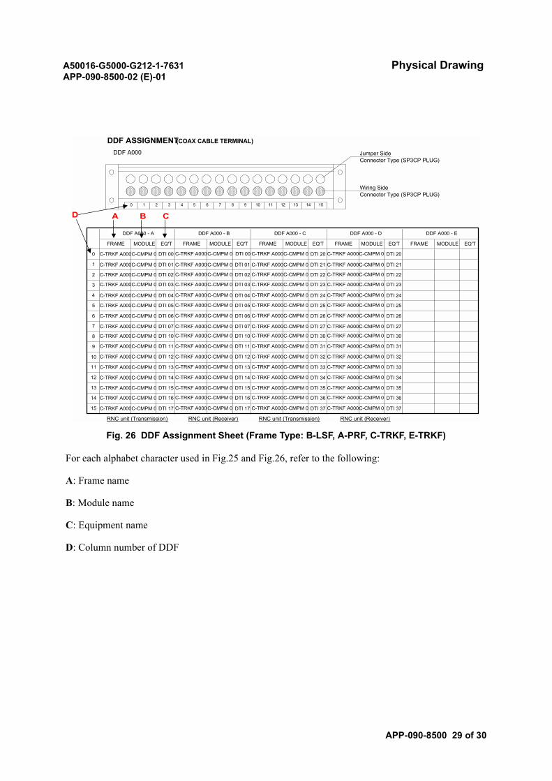
A50016-G5000-G212-1-7631 Physical DrawingAPP-090-8500-02 (E)-01
APP-090-8500 29 of 30
Fig. 26 DDF Assignment Sheet (Frame Type: B-LSF, A-PRF, C-TRKF, E-TRKF)
For each alphabet character used in Fig.25 and Fig.26, refer to the following:
A: Frame name
B: Module name
C: Equipment name
D: Column number of DDF
14 1510 11 12 13
Wiring SideConnector Type (SP3CP PLUG)
0 1 2 3 4 5 6 7
DDF A000 Jumper SideConnector Type (SP3CP PLUG)
RNC unit (Transmission) RNC unit (Receiver) RNC unit (Transmission) RNC unit (Receiver)
MODULE
DTI 20
MODULE EQ'T FRAMEFRAMEFRAME MODULE
DDF A000 - E
EQ'T
DDF A000 - D
15
14
13
12
11
6
5
4
FRAME
0 C-TRKF A000
MODULE
C-CMPM 0
DDF A000 - A
EQ'T
DTI 00
1
3
2
8
DDF A000 - B
EQ'T
9
8
7
10
9
DDF ASSIGNMENT(COAX CABLE TERMINAL)
DDF A000 - C
FRAME MODULE EQ'T
A B CD
C-TRKF A000C-CMPM 0 DTI 00 C-TRKF A000C-CMPM 0 DTI 20C-TRKF A000C-CMPM 0
C-TRKF A000C-CMPM 0 DTI 01 C-TRKF A000C-CMPM 0 DTI 21C-TRKF A000C-CMPM 0 C-TRKF A000C-CMPM 0
C-TRKF A000C-CMPM 0 DTI 02 C-TRKF A000C-CMPM 0 DTI 22C-TRKF A000C-CMPM 0 C-TRKF A000C-CMPM 0
C-TRKF A000C-CMPM 0 DTI 03 C-TRKF A000C-CMPM 0 DTI 23C-TRKF A000C-CMPM 0 C-TRKF A000C-CMPM 0
C-TRKF A000C-CMPM 0 DTI 04 C-TRKF A000C-CMPM 0 DTI 24C-TRKF A000C-CMPM 0 C-TRKF A000C-CMPM 0
C-TRKF A000C-CMPM 0 DTI 05 C-TRKF A000C-CMPM 0 DTI 25C-TRKF A000C-CMPM 0 C-TRKF A000C-CMPM 0
C-TRKF A000C-CMPM 0 DTI 06 C-TRKF A000C-CMPM 0 DTI 26C-TRKF A000C-CMPM 0 C-TRKF A000C-CMPM 0
C-TRKF A000C-CMPM 0 DTI 07 C-TRKF A000C-CMPM 0 DTI 27C-TRKF A000C-CMPM 0 C-TRKF A000C-CMPM 0
C-TRKF A000C-CMPM 0 DTI 10 C-TRKF A000C-CMPM 0 DTI 30C-TRKF A000C-CMPM 0 C-TRKF A000C-CMPM 0
C-TRKF A000C-CMPM 0 DTI 11 C-TRKF A000C-CMPM 0 DTI 31C-TRKF A000C-CMPM 0 C-TRKF A000C-CMPM 0
C-TRKF A000C-CMPM 0 DTI 12 C-TRKF A000C-CMPM 0 DTI 32C-TRKF A000C-CMPM 0 C-TRKF A000C-CMPM 0
C-TRKF A000C-CMPM 0 DTI 13 C-TRKF A000C-CMPM 0 DTI 33C-TRKF A000C-CMPM 0 C-TRKF A000C-CMPM 0
C-TRKF A000C-CMPM 0 DTI 14 C-TRKF A000C-CMPM 0 DTI 34C-TRKF A000C-CMPM 0 C-TRKF A000C-CMPM 0
C-TRKF A000C-CMPM 0 DTI 15 C-TRKF A000C-CMPM 0 DTI 35C-TRKF A000C-CMPM 0 C-TRKF A000C-CMPM 0
C-TRKF A000C-CMPM 0 DTI 16 C-TRKF A000C-CMPM 0 DTI 36C-TRKF A000C-CMPM 0 C-TRKF A000C-CMPM 0
C-TRKF A000C-CMPM 0 DTI 17 C-TRKF A000C-CMPM 0 DTI 37C-TRKF A000C-CMPM 0 C-TRKF A000C-CMPM 0
DTI 01
DTI 02
DTI 03
DTI 04
DTI 05
DTI 06
DTI 07
DTI 10
DTI 11
DTI 12
DTI 13
DTI 14
DTI 15
DTI 16
DTI 17
DTI 21
DTI 22
DTI 23
DTI 24
DTI 25
DTI 26
DTI 27
DTI 30
DTI 31
DTI 32
DTI 33
DTI 34
DTI 35
DTI 36
DTI 37
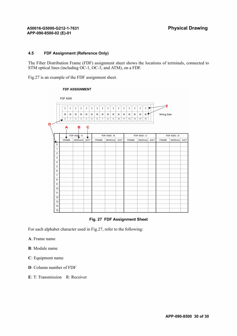
A50016-G5000-G212-1-7631 Physical DrawingAPP-090-8500-02 (E)-01
APP-090-8500 30 of 30
4.5 FDF Assignment (Reference Only)
The Fiber Distribution Frame (FDF) assignment sheet shows the locations of terminals, connected toSTM optical lines (including OC-1, OC-3, and ATM), on a FDF.
Fig.27 is an example of the FDF assignment sheet.
Fig. 27 FDF Assignment Sheet
For each alphabet character used in Fig.27, refer to the following:
A: Frame name
B: Module name
C: Equipment name
D: Column number of FDF
E: T: Transmission R: Receiver
MODULE EQ'TFRAME EQ'TEQ'T
FDF A000 - D
15
14
13
12
11
6
5
4
FRAME
0
MODULE
1
3
2
R R R
6 7
MODULE
R R R RR
T T T T
13 14 158 9 10 11 12
T
R R R R R R R R
T T T T
8
7
10
9
T T
FDF ASSIGNMENT
T T T
FDF A000
T T
0 1 2
FDF A000 - A
3 4 5
FDF A000 - B FDF A000 - C
FRAME MODULE EQ'T FRAME
WirIng Side
A B CD
E
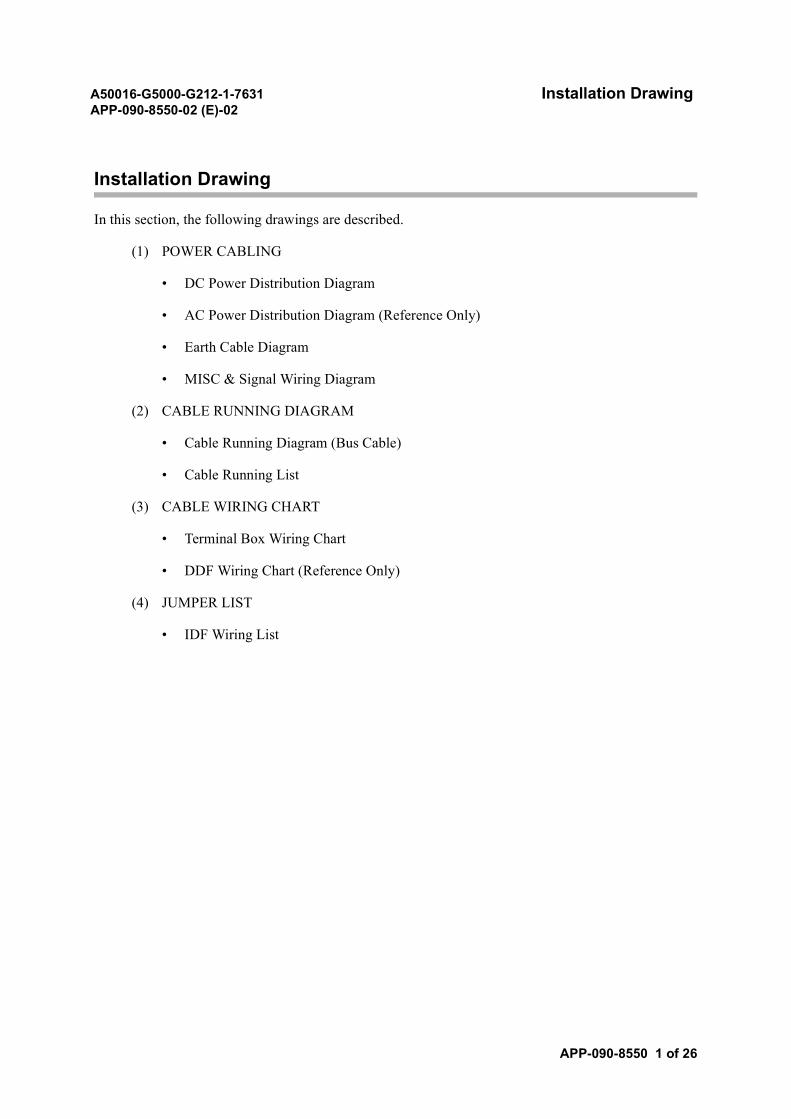
A50016-G5000-G212-1-7631 Installation DrawingAPP-090-8550-02 (E)-02
APP-090-8550 1 of 26
Installation Drawing
In this section, the following drawings are described.
(1) POWER CABLING
• DC Power Distribution Diagram
• AC Power Distribution Diagram (Reference Only)
• Earth Cable Diagram
• MISC & Signal Wiring Diagram
(2) CABLE RUNNING DIAGRAM
• Cable Running Diagram (Bus Cable)
• Cable Running List
(3) CABLE WIRING CHART
• Terminal Box Wiring Chart
• DDF Wiring Chart (Reference Only)
(4) JUMPER LIST
• IDF Wiring List
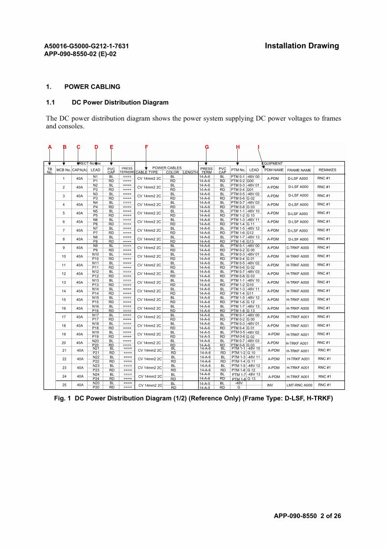
A50016-G5000-G212-1-7631 Installation DrawingAPP-090-8550-02 (E)-02
APP-090-8550 2 of 26
1. POWER CABLING
1.1 DC Power Distribution Diagram
The DC power distribution diagram shows the power system supplying DC power voltages to framesand consoles.
Fig. 1 DC Power Distribution Diagram (1/2) (Reference Only) (Frame Type: D-LSF, H-TRKF)
14-A-6RD 14-A-6
RECT No.xxxPOWER CABLESTB
No, MCB No, CAPA(A) LEAD PVCCAP
PRESSTERM(M8) FRAME NAME REMAKESCABLE TYPE COLOR LENGTH
PRESSTERM
PVCCAP PTM No, PDM NAMELEAD
1 40A N1P1
2 40A N2P2
3
BL ====
BL ====
40A N3 BL ====
CV 14mm2 2C BLRD ==== RD A-PDM D-LSF A000 RNC #114-A-6 BL PTM 0-1
14-A-6 RD PTM 0-2
CV 14mm2 2C BLRD ==== RD A-PDM RNC #114-A-6 BL PTM 0-3
14-A-6 RD PTM 0-4
A-PDMCV 14mm2 2C BL 14-A-6 -48V 02G 02
RNC #1P3 RD ==== RD 14-A-6 RD PTM 0-6
BL PTM 0-5
4 40A N4 BL BL PTM 0-7 A-PDM==== CV 14mm2 2C BLG 03-48V 03 RNC #1
P4 RD ==== RD 14-A-6 RD PTM 0-814-A-6
5 40A N5 BL BL PTM 1-1 A-PDM==== CV 14mm2 2C BL -48V 10G 10
RNC #1P5 RD ==== RD 14-A-6 RD PTM 1-2
14-A-6
6 40A N6 BL BL PTM 1-3 A-PDM==== CV 14mm2 2C BLG 11-48V 11 RNC #1
P6 RD ==== RD 14-A-6 RD PTM 1-414-A-6
7 40A N7 BL BL PTM 1-5 A-PDM==== CV 14mm2 2C BL -48V 12G12
RNC #1P7 RD ==== RD 14-A-6 RD PTM 1-6
14-A-6
8 40A N8 BL BL PTM 1-7 A-PDM==== CV 14mm2 2C BLG13-48V 13 RNC #1
P8 RD ==== RD 14-A-6 RD PTM 1-814-A-6
9 40A N9 BL BL PTM 0-1 A-PDM==== CV 14mm2 2C BL -48V 00G 00 C-TRKF A000 RNC #1
P9 RD ==== RD 14-A-6 RD PTM 0-214-A-6
10 40A N10 BL BL PTM 0-3 A-PDM==== CV 14mm2 2C BL -48V 01G 01 H-TRKF A000 RNC #1
P10 RD ==== RD 14-A-6 RD PTM 0-414-A-6
11 40A N11 BL BL PTM 0-5 A-PDM==== CV 14mm2 2C BL -48V 02G 02 H-TRKF A000 RNC #1
P11 RD ==== RD 14-A-6 RD PTM 0-614-A-6
12 40A N12 BL BL PTM 0-7 A-PDM==== CV 14mm2 2C BL -48V 03G 03 H-TRKF A000 RNC #1
P12 RD ==== RD 14-A-6 RD PTM 0-814-A-6
13 40A N13 BL BL PTM 1-1 A-PDM==== CV 14mm2 2C BL -48V 10G10 H-TRKF A000 RNC #1
P13 RD ==== RD 14-A-6 RD PTM 1-214-A-6
14 40A N14 BL BL PTM 1-3 A-PDM==== CV 14mm2 2C BLG11-48V 11 H-TRKF A000 RNC #1
P14 RD ==== RD 14-A-6 RD PTM 1-414-A-6
15 40A N15 BL BL PTM 1-5 A-PDM==== CV 14mm2 2C BL -48V 12G 12 H-TRKF A000 RNC #1
P15 RD ==== RD 14-A-6 RD PTM 1-614-A-6
16 40A N16 BL BL PTM 1-7 A-PDM==== CV 14mm2 2C BL -48V 13G 13 H-TRKF A000 RNC #1
P16 RD ==== RD 14-A-6 RD PTM 1-814-A-6
17 40A N17 BL BL PTM 0-1 A-PDM==== CV 14mm2 2C BL -48V 00G 00 H-TRKF A001 RNC #1
P17 RD ==== RD 14-A-6 RD PTM 0-214-A-6
==== -48V 01G 0118 40A N18 BL CV 14mm2 2C BL H-TRKF A001 RNC #1
P18 RD ==== RD PTM 0-4BL PTM 0-3 A-PDM
19 40A N19 BL BL==== CV 14mm2 2C BL RNC #1P19 RD ==== RD 14-A-5 RD
14-A-5
20 40A N20 BLP20 RD
========
EQUIPMENT
-48V 00G00-48V 01G01
A B C D E F G H I
D-LSF A000
D-LSF A000
D-LSF A000
D-LSF A000
D-LSF A000
14-A-6RD 14-A-6
21 40A N21 BL BL PTM 1-1 A-PDM==== CV 14mm2 2C BL -48V 10G 10 H-TRKF A001 RNC #1
P21 RD ==== RD 14-A-6 RD PTM 1-214-A-6
22 40A N22 BL BL PTM 1-3 A-PDM==== CV 14mm2 2C BL -48V 11G 11 H-TRKF A001 RNC #1
P22 RD ==== RD 14-A-6 RD PTM 1-414-A-6
==== -48V 12G 1223 40A N23 BL CV 14mm2 2C BL H-TRKF A001 RNC #1
P23 RD ==== RD PTM 1-6BL PTM 1-5 A-PDM
24 40A N24 BL
BL -48V INV
====
CV 14mm2 2C BL LMT-RNC A000 RNC #1
P24 RD ====
RD 14-A-5 RD G14-A-525 40A N20 BL
P20 RD========
PTM 1-7PTM 1-8
-48V 13G 13 H-TRKF A001 RNC #1A-PDMCV 14mm2 2C
RDBL 14-A-6
14-A-6 RDBL
BL PTM 0-7 A-PDMCV 14mm2 2C BL -48V 03G 03 H-TRKF A001 RNC #1
RD 14-A-6 RD PTM 0-814-A-6
PTM 0-5PTM 0-6
-48V 02G 02
A-PDM H-TRKF A001
D-LSF A000
D-LSF A000
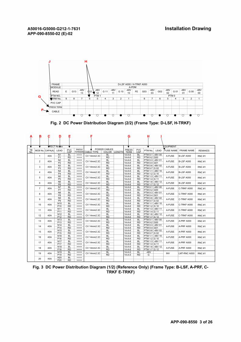
A50016-G5000-G212-1-7631 Installation DrawingAPP-090-8550-02 (E)-02
APP-090-8550 3 of 26
Fig. 2 DC Power Distribution Diagram (2/2) (Frame Type: D-LSF, H-TRKF)
Fig. 3 DC Power Distribution Diagram (1/2) (Reference Only) (Frame Type: B-LSF, A-PRF, C-TRKF E-TRKF)
J H
G
F
A-PDM
E
PTM 04 37 6 1
CABLE
PTM 117 3 2 8
PRESS TERM
PVC CAP
6PTM NO,
G 00
5
FRAME
TERM No, 8
G13
9
D-LSF A000 / H-TRKF A000
READ
5 4
G12 -48V12 G 11 -48V
00
MODULE
G 01 -48V01
-48V13 G02G 10 -48V
02-48V11
2
-48V10 G03FE -48V
03
14-A-6RD 14-A-6
RECT No.xxxPOWER CABLESTB
No, MCB No, CAPA(A) LEAD PVCCAP
PRESSTERM(M8) FRAME NAME REMAKESCABLE TYPE COLOR LENGTH
PRESSTERM
PVCCAP PTM No, FUSE NAMELEAD
1 40A N1P1
2 40A N2P2
3
BL ====
BL ====
40A N3 BL ====
CV 14mm2 2C BLRD ==== RD A-FUSE B-LSF A000 RNC #114-A-6 BL PTM 0-1
14-A-6 RD PTM 0-2
CV 14mm2 2C BLRD ==== RD A-FUSE B-LSF A000 RNC #114-A-6 BL PTM 0-3
14-A-6 RD PTM 0-4
A-FUSE B-LSF A000CV 14mm2 2C BL 14-A-6 -48V 02G 02 RNC #1P3 RD ==== RD 14-A-6 RD PTM 0-7
BL PTM 0-6
4 40A N4 BL BL PTM 1-1 A-FUSE==== CV 14mm2 2C BLG 10-48V 10 B-LSF A000 RNC #1P4 RD ==== RD 14-A-6 RD PTM 1-2
14-A-6
5 40A N5 BL BL PTM 1-3 A-FUSE==== CV 14mm2 2C BL -48V 11G 11 B-LSF A000 RNC #1P5 RD ==== RD 14-A-6 RD PTM 1-4
14-A-6
6 40A N6 BL BL PTM 1-6 A-FUSE==== CV 14mm2 2C BLG 12-48V 12 B-LSF A000 RNC #1P6 RD ==== RD 14-A-6 RD PTM 1-7
14-A-6
7 40A N7 BL BL PTM 0-1 A-FUSE==== CV 14mm2 2C BL -48V 00G00 C-TRKF A000 RNC #1P7 RD ==== RD 14-A-6 RD PTM 0-2
14-A-6
8 40A N8 BL BL PTM 0-3 A-FUSE==== CV 14mm2 2C BLG01-48V 01 C-TRKF A000 RNC #1P8 RD ==== RD 14-A-6 RD PTM 0-4
14-A-6
9 40A N9 BL BL PTM 0-6 A-FUSE==== CV 14mm2 2C BL -48V 02G 02 C-TRKF A000 RNC #1P9 RD ==== RD 14-A-6 RD PTM 0-7
14-A-6
10 40A N10 BL BL PTM 1-1 A-FUSE==== CV 14mm2 2C BL -48V 10G 10 C-TRKF A000 RNC #1P10 RD ==== RD 14-A-6 RD PTM 1-2
14-A-6
11 40A N11 BL BL PTM 1-3 A-FUSE==== CV 14mm2 2C BL -48V 11G 11 C-TRKF A000 RNC #1P11 RD ==== RD 14-A-6 RD PTM 1-4
14-A-6
12 40A N12 BL BL PTM 1-6 A-FUSE==== CV 14mm2 2C BL -48V 12G 12 C-TRKF A000 RNC #1P12 RD ==== RD 14-A-6 RD PTM 1-7
14-A-6
13 40A N13 BL BL PTM 0-1 A-FUSE==== CV 14mm2 2C BL -48V 00G00 A-PRF A000 RNC #1P13 RD ==== RD 14-A-6 RD PTM 0-2
14-A-6
14 40A N14 BL BL PTM 0-3 A-FUSE==== CV 14mm2 2C BLG01-48V 01 A-PRF A000 RNC #1P14 RD ==== RD 14-A-6 RD PTM 0-4
14-A-6
15 40A N15 BL BL PTM 0-6 A-FUSE==== CV 14mm2 2C BL -48V 02G 02 A-PRF A000 RNC #1P15 RD ==== RD 14-A-6 RD PTM 0-7
14-A-6
16 40A N16 BL BL PTM 1-1 A-FUSE==== CV 14mm2 2C BL -48V 10G 10 A-PRF A000 RNC #1P16 RD ==== RD 14-A-6 RD PTM 1-2
14-A-6
17 40A N17 BL BL PTM 1-3 A-FUSE==== CV 14mm2 2C BL -48V 11G 11 A-PRF A000 RNC #1P17 RD ==== RD 14-A-6 RD PTM 1-4
14-A-6
==== -48V 12G 1218 40A N18 BL CV 14mm2 2C BL A-PRF A000 RNC #1P18 RD ==== RD PTM 1-7
BL PTM 1-6 A-FUSE
19 40A N19 BL BL -48V INV==== CV 14mm2 2C BL LMT-RNC A000 RNC #1P19 RD ==== RD 14-A-5 RD G14-A-5
20 40A N20 BLP20 RD
========
EQUIPMENT
-48V 00G00-48V 01G01
A B C D E F G H I
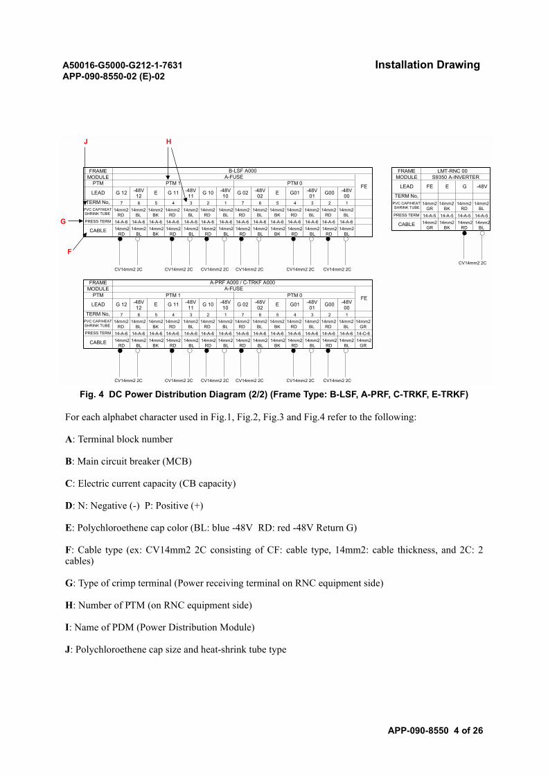
A50016-G5000-G212-1-7631 Installation DrawingAPP-090-8550-02 (E)-02
APP-090-8550 4 of 26
Fig. 4 DC Power Distribution Diagram (2/2) (Frame Type: B-LSF, A-PRF, C-TRKF, E-TRKF)
For each alphabet character used in Fig.1, Fig.2, Fig.3 and Fig.4 refer to the following:
A: Terminal block number
B: Main circuit breaker (MCB)
C: Electric current capacity (CB capacity)
D: N: Negative (-) P: Positive (+)
E: Polychloroethene cap color (BL: blue -48V RD: red -48V Return G)
F: Cable type (ex: CV14mm2 2C consisting of CF: cable type, 14mm2: cable thickness, and 2C: 2cables)
G: Type of crimp terminal (Power receiving terminal on RNC equipment side)
H: Number of PTM (on RNC equipment side)
I: Name of PDM (Power Distribution Module)
J: Polychloroethene cap size and heat-shrink tube type
CABLE
PRESS TERM
PVC CAP/HEATSHRINK TUBE
TERM No, 7 6 5
-48V12 E G 11 -48V
11
FRAME A-PRF A000 / C-TRKF A000MODULE A-FUSE
FEPTM PTM 1 PTM 0
LEAD G 12
FRAME B-LSF A000
PTMMODULE A-FUSE
FEPTM 1 PTM 0
LEAD G 12 -48V12 E G 11 -48V
11 G 10 -48V10 G 02 -48V
02 E G01 -48V01 G00 -48V
00TERM No, 7 6 5 4 3 2 11 7 6 5
PVC CAP/HEATSHRINK TUBE
4 3 2
PRESS TERM
CABLE
CV14mm2 2C
G 10 -48V10 G 02 -48V
02 E G01 -48V01 G00 -48V
004 3 2 1 7 6 5 4 3 2 1
FRAME LMT-RNC 00
FE E G
MODULE S9350 A-INVERTER
-48VLEAD
TERM No,
14mm2GR
14mm2BK
14mm2RD
14-A-5 14-A-5 14-A-5
14mm2GR
14mm2BK
14mm2RD
CABLE
PRESS TERM
PVC CAP/HEATSHRINK TUBE
14mm2BL
14-A-5
14mm2BL14mm2
RD14-A-6
14mm2RD
14mm2RD
14-A-6 14mm2
RD
14mm2RD
14-A-6 14mm2
RD
14mm2RD
14-A-6 14mm2
RD
14mm2RD
14-A-6 14mm2
RD
14mm2RD
14-A-6 14mm2
RD
14mm2RD
14-A-6 14mm2
RD
14mm2RD
14-A-6 14mm2
RD
14mm2RD
14-A-6 14mm2
RD
14mm2RD
14-A-6 14mm2
RD
14mm2RD
14-A-6 14mm2
RD
14mm2RD
14-A-6 14mm2
RD
14mm2BL
14-A-6 14mm2
BL
14mm2BL
14-A-6 14mm2
BL
14mm2BL
14-A-6 14mm2
BL
14mm2BL
14-A-6 14mm2
BL
14mm2BL
14-A-6 14mm2
BL
14mm2BL
14-A-6 14mm2
BL
14mm2BL
14-A-6 14mm2
BL
14mm2BL
14-A-6 14mm2
BL
14mm2BL
14-A-6 14mm2
BL
14mm2BL
14-A-6 14mm2
BL
14mm2BL
14-A-6 14mm2
BL
14mm2BL
14-A-6 14mm2
BL
14mm2BK
14-A-6 14mm2
BK
14mm2BK
14-A-6 14mm2
BK
14mm2BK
14-A-6 14mm2
BK
14mm2BK
14-A-6 14mm2
BK
14mm2GR
14-C-6 14mm2
GR
CV14mm2 2C CV14mm2 2C CV14mm2 2C CV14mm2 2C CV14mm2 2C
CV14mm2 2C CV14mm2 2C CV14mm2 2C CV14mm2 2C CV14mm2 2C CV14mm2 2C
CV14mm2 2C
J H
G
F
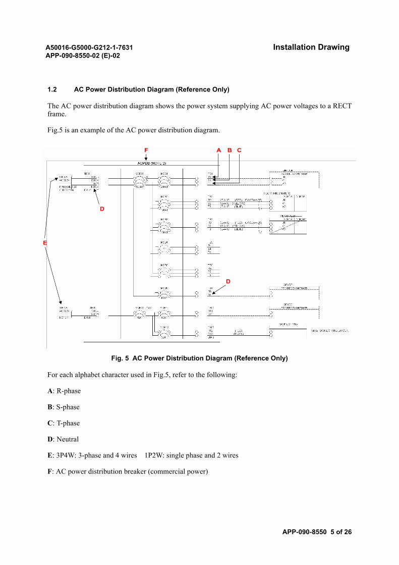
A50016-G5000-G212-1-7631 Installation DrawingAPP-090-8550-02 (E)-02
APP-090-8550 5 of 26
1.2 AC Power Distribution Diagram (Reference Only)
The AC power distribution diagram shows the power system supplying AC power voltages to a RECTframe.
Fig.5 is an example of the AC power distribution diagram.
Fig. 5 AC Power Distribution Diagram (Reference Only)
For each alphabet character used in Fig.5, refer to the following:
A: R-phase
B: S-phase
C: T-phase
D: Neutral
E: 3P4W: 3-phase and 4 wires 1P2W: single phase and 2 wires
F: AC power distribution breaker (commercial power)
F A B C
D
E
D
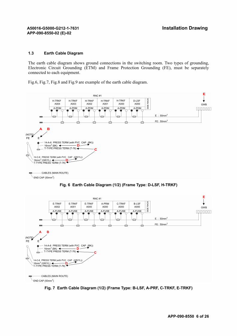
A50016-G5000-G212-1-7631 Installation DrawingAPP-090-8550-02 (E)-02
APP-090-8550 6 of 26
1.3 Earth Cable Diagram
The earth cable diagram shows ground connections in the switching room. Two types of grounding,Electronic Circuit Grounding (ETM) and Frame Protection Grounding (FE), must be separatelyconnected to each equipment.
Fig.6, Fig.7, Fig.8 and Fig.9 are example of the earth cable diagram.
Fig. 6 Earth Cable Diagram (1/2) (Frame Type: D-LSF, H-TRKF)
Fig. 7 Earth Cable Diagram (1/2) (Frame Type: B-LSF, A-PRF, C-TRKF, E-TRKF)
END CAP (50mm2)
16mm2 (GR/YL)T-TYPE PRESS TERM (T-76)
CABLES (MAIN ROUTE)
14-A-6 PRESS TERM (with PVC CAP (BK))16mm2 (BK)T-TYPE PRESS TERM (T-76)
14-C-6 PRESS TERM (with PVC CAP (GR/YL))
E : 50mm2
FE: 50mm2
(NOTE)FE E
A-PDM A-PDM A-PDM A-PDM
A000D-LSFA000
SID
E R
AC
K
GWBA-PDM A-PDM
H-TRKFA004
H-TRKFA003 A002 A001
RNC #1 E
A B
DC
D
H-TRKF H-TRKF H-TRKF
END CAP (50mm2)
16mm2 (GR/YL)T-TYPE PRESS TERM (T-76)
CABLES (MAIN ROUTE)
14-A-6 PRESS TERM (with PVC CAP (BK))16mm2 (BK)T-TYPE PRESS TERM (T-76)
14-C-6 PRESS TERM (with PVC CAP (GR/YL))
E : 50mm2
FE: 50mm2
(NOTE)FE E
A-FUSE A-FUSE A-FUSE A-FUSE
C-TRKFA000
B-LSFA000
SID
E R
AC
K
GWBA-FUSE A-FUSE
E-TRKFA002
E-TRKFA001
E-TRKFA000
A-PRMA000
RNC #1 E
A B
DC
D
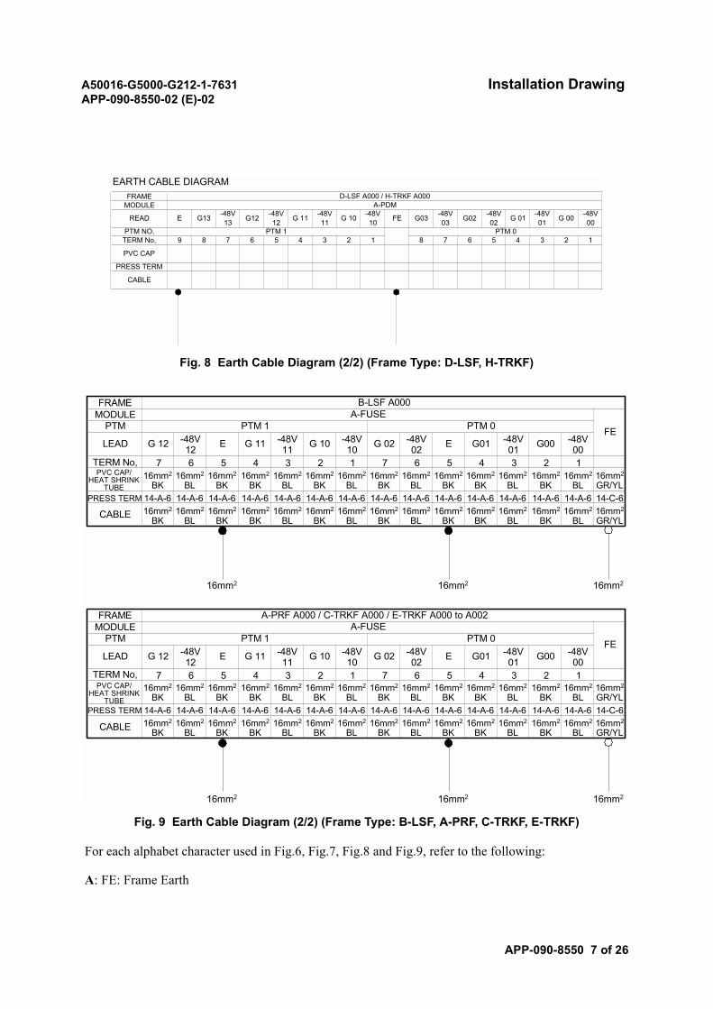
A50016-G5000-G212-1-7631 Installation DrawingAPP-090-8550-02 (E)-02
APP-090-8550 7 of 26
Fig. 8 Earth Cable Diagram (2/2) (Frame Type: D-LSF, H-TRKF)
Fig. 9 Earth Cable Diagram (2/2) (Frame Type: B-LSF, A-PRF, C-TRKF, E-TRKF)
For each alphabet character used in Fig.6, Fig.7, Fig.8 and Fig.9, refer to the following:
A: FE: Frame Earth
12 8
CABLE
PRESS TERM
PVC CAP
9 8 7 6 4 3 5 4 3 2PTM NO,TERM No, 5
-48V12 G02 -48V
02 G 01 -48V01 G 00 -48V
00
FRAMEMODULE
READ E
D-LSF A000 / H-TRKF A000A-PDM
G13 -48V13 G12
EARTH CABLE DIAGRAM
G 11 -48V11 G 10 -48V
10 FE G03 -48V03
7 6PTM 1 PTM 0
1
FRAME B-LSF A000MODULE A-FUSE
FEPTM PTM 1 PTM 0
LEAD G 12 -48V12 E G 11 -48V
11 G 10 -48V10 G 02 -48V
02 E G01 -48V01 G00 -48V
00TERM No, 7 6 5 4 3 2 1 7 6 5 4 3 2 1
PRESS TERM
CABLE
16mm2
FRAME A-PRF A000 / C-TRKF A000 / E-TRKF A000 to A002MODULE A-FUSE
FEPTM PTM 1 PTM 0
LEAD G 12 -48V12 E G 11 -48V
11 G 10 -48V10 G 02 -48V
02 E G01 -48V01 G00 -48V
007 6 5 4 3 2 1 7 6 5 4 3 2 1
CABLE
PVC CAP/HEAT SHRINK
TUBE
TERM No,
PRESS TERM
PVC CAP/HEAT SHRINK
TUBE
16mm2
BK14-A-616mm2
BK
16mm2
BL14-A-616mm2
BL
16mm2
BK14-A-616mm2
BK
16mm2
BK14-A-616mm2
BK
16mm2
BK14-A-616mm2
BK
16mm2
BK14-A-616mm2
BK
16mm2
BK14-A-616mm2
BK
16mm2
BK14-A-616mm2
BK
16mm2
BK14-A-616mm2
BK
16mm2
BL14-A-616mm2
BL
16mm2
BL14-A-616mm2
BL
16mm2
BL14-A-616mm2
BL
16mm2
BL14-A-616mm2
BL
16mm2
BL14-A-616mm2
BL
16mm2
GR/YL14-C-616mm2
GR/YL
16mm2 16mm2
16mm2 16mm2 16mm2
16mm2
BK14-A-616mm2
BK
16mm2
BL14-A-616mm2
BL
16mm2
BK14-A-616mm2
BK
16mm2
BK14-A-616mm2
BK
16mm2
BK14-A-616mm2
BK
16mm2
BK14-A-616mm2
BK
16mm2
BK14-A-616mm2
BK
16mm2
BK14-A-616mm2
BK
16mm2
BK14-A-616mm2
BK
16mm2
BL14-A-616mm2
BL
16mm2
BL14-A-616mm2
BL
16mm2
BL14-A-616mm2
BL
16mm2
BL14-A-616mm2
BL
16mm2
BL14-A-616mm2
BL
16mm2
GR/YL14-C-616mm2
GR/YL

A50016-G5000-G212-1-7631 Installation DrawingAPP-090-8550-02 (E)-02
APP-090-8550 8 of 26
B: E: Earth (Logical Earth)
C: Crimp terminal type
D: BK: black Earth; GR: green Frame Earth; GR/YL: green/yellow Frame Earth
E: GWB: ground window bar
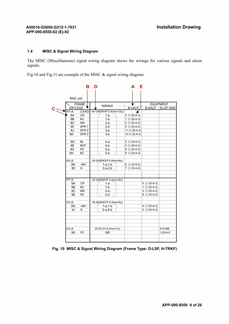
A50016-G5000-G212-1-7631 Installation DrawingAPP-090-8550-02 (E)-02
APP-090-8550 9 of 26
1.4 MISC & Signal Wiring Diagram
The MISC (Miscellaneous) signal wiring diagram shows the wirings for various signals and alarmsignals.
Fig.10 and Fig.11 are example of the MISC & signal wiring diagram.
Fig. 10 MISC & Signal Wiring Diagram (Frame Type: D-LSF, H-TRKF)
9G -48V9J G
9C MN9E FE
H1-A
H1-A
H1-A8N -48V
8E BOF9G FE
8J SPR 28K SPR 3
8B MJ8C MN
H1-A (LEAD)8A CR
1.25-A-59S FE GRA-FUSEH1-A W-5(TJV 0.4mm×1c)
2-a,2-b 5 (1.25-A-3)1-a,1-b 4 (1.25-A-3)
W-4(NSWVP 0.4mm×6c)
6 (1.25-A-3)2-b2-a 2 (1.25-A-3)
1 (1.25-A-3)9B MJ 1-b1-a 0 (1.25-A-3)9A CR
W-3(NSWVP 0.4mm×6c)
2-a,2-b 7 (1.25-A-3)80 G1-a,1-b 6 (1.25-A-3)
W-2(NSWVP 0.4mm×6c)
5-b 9 (1.25-A-3)9H BC5-a 8 (1.25-A-3)4-b 4 (1.25-A-3)
8D BL 4-a 3 (1.25-A-3)
3-b 10 (1.25-A-3)3-a 11 (1.25-A-3)
8F SPR 1 2-b 5 (1.25-A-3)2-a 2 (1.25-A-3)1-b 1 (1.25-A-3)
W-1(NSWVP 0.4mm×12c)1-a 0 (1.25-A-3)
B-LSF A000EQUIPMENTFRAME
IDF/LEADWIRING
B-VALP B-AALP
RNC unit
B D A E
C
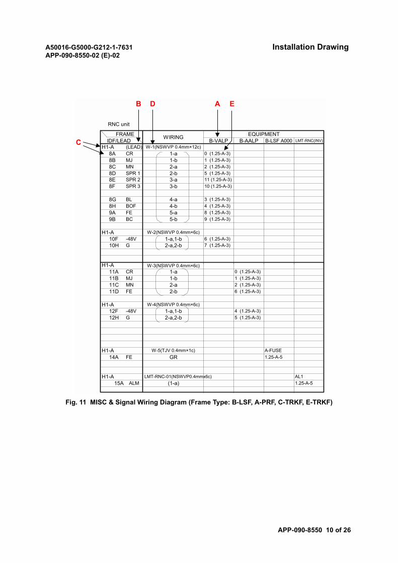
A50016-G5000-G212-1-7631 Installation DrawingAPP-090-8550-02 (E)-02
APP-090-8550 10 of 26
Fig. 11 MISC & Signal Wiring Diagram (Frame Type: B-LSF, A-PRF, C-TRKF, E-TRKF)
12F -48V
H1-A
12H G
11C MN11D FE
H1-A
H1-A
H1-A10F -48V
8H BOF9A FE
8E SPR 28F SPR 3
8B MJ8C MN
H1-A (LEAD)8A CR
1.25-A-5AL1
15A ALM (1-a)LMT-RNC-01(NSWVP0.4mmx6c)
1.25-A-514A FE GRA-FUSEH1-A W-5(TJV 0.4mm×1c)
2-a,2-b 5 (1.25-A-3)1-a,1-b 4 (1.25-A-3)
W-4(NSWVP 0.4mm×6c)
6 (1.25-A-3)2-b2-a 2 (1.25-A-3)
1 (1.25-A-3)11B MJ 1-b1-a 0 (1.25-A-3)11A CR
W-3(NSWVP 0.4mm×6c)
2-a,2-b 7 (1.25-A-3)10H G1-a,1-b 6 (1.25-A-3)
W-2(NSWVP 0.4mm×6c)
5-b 9 (1.25-A-3)9B BC5-a 8 (1.25-A-3)4-b 4 (1.25-A-3)
8G BL 4-a 3 (1.25-A-3)
3-b 10 (1.25-A-3)3-a 11 (1.25-A-3)
8D SPR 1 2-b 5 (1.25-A-3)2-a 2 (1.25-A-3)1-b 1 (1.25-A-3)
W-1(NSWVP 0.4mm×12c)1-a 0 (1.25-A-3)
B-LSF A000 LMT-RNC(INV)EQUIPMENTFRAME
IDF/LEADWIRING
B-VALP B-AALP
RNC unit
B D A E
C

A50016-G5000-G212-1-7631 Installation DrawingAPP-090-8550-02 (E)-02
APP-090-8550 11 of 26
For each alphabet character used in Fig.10 and Fig.11, refer to the following:
A: Equipment name
B: Lead name
C: Terminal block and pin number
D: Cable number
E: Crimp terminal specification
For the details of the lead names, refer to IDF Assignment.
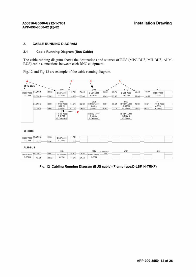
A50016-G5000-G212-1-7631 Installation DrawingAPP-090-8550-02 (E)-02
APP-090-8550 12 of 26
2. CABLE RUNNING DIAGRAM
2.1 Cable Running Diagram (Bus Cable)
The cable running diagram shows the destinations and sources of BUS (MPC-BUS, MH-BUS, ALM-BUS) cable connections between each RNC equipment.
Fig.12 and Fig.13 are example of the cable running diagram.
Fig. 12 Cabling Running Diagram (BUS cable) (Frame type:D-LSF, H-TRKF)
A B C D
D-CCPM A-PDM A-PDM10.C1
H-TRKF A000
(02)(01) (03)C-R26YB (RES)
D-CCPM E-CCPM10.C3 11.A2 11.B1
05.A04.A3
04.A2
04.A1
11.A1 D-LSF A000 11.A3
04.A1
ALM-BUS
D-LSF A000 09.CN0.0 D-LSF A000
MH-BUS
(00)
04.B1 04.A2
D-LSF A000 09.CN0.2
B-PRM 0(S.Basic)
H-TRKF A000
29.A3
(10)
MPC-BUS(00) (01)
D-CCPMD-LSF A000
(02) (03)26.A2 10.A2 25.A2D-LSF A000 D-LSF A000
E-CCPMD-LSF A000 24.CN0.1 30.A2 D-LSF A000 06.A2 29.A2
C-LSM
130.A1
130.A2E-CCPM06.A3 10.A3 25.A330.A325.CN0.1 26.A3D-CCPM
(08) (09) (11)24.CN0.2 02.C1 H-TRKF A000 04.C1 02.C1 H-TRKF A000 04.C1 09.C1
B-MHM B-SIGM C-GTPM A-DTIMH-TRKF A000 13.C1 02.C1 H-TRKF A000
25.CN0.2 04.C2 (P.Basic) 02.C2 04.C2 (P.Basic) 02.C2 (P.Basic)13.C2 (P.Basic) 09.C2 04.C2
(P.Extended) (P.Extended)
H-TRKF A000 H-TRKF A000C-DHTM C-M2CM
E
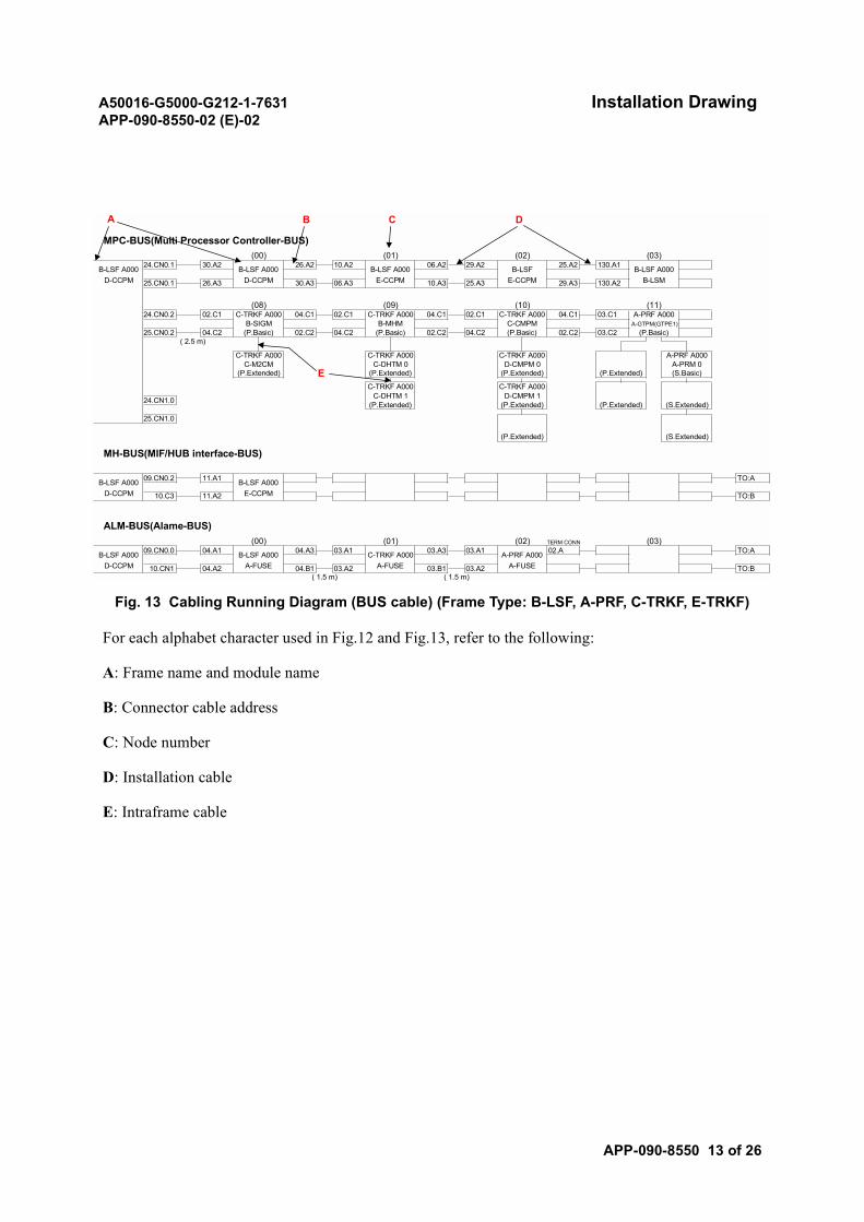
A50016-G5000-G212-1-7631 Installation DrawingAPP-090-8550-02 (E)-02
APP-090-8550 13 of 26
Fig. 13 Cabling Running Diagram (BUS cable) (Frame Type: B-LSF, A-PRF, C-TRKF, E-TRKF)
For each alphabet character used in Fig.12 and Fig.13, refer to the following:
A: Frame name and module name
B: Connector cable address
C: Node number
D: Installation cable
E: Intraframe cable
25.CN1.0
TO:B( 1.5 m) ( 1.5 m)
03.A2 03.B1 03.A210.CN1 04.A2D-CCPM A-FUSE A-FUSE A-FUSE04.B1
TERM CONNTO:AB-LSF A000 09.CN0.0 04.A1 B-LSF A000 04.A3 03.A1 C-TRKF A000
(03)(02)03.A3 03.A1 A-PRF A000 02.A
ALM-BUS(Alame-BUS)(00) (01)
TO:B
TO:A
D-CCPM E-CCPM10.C3 11.A2
B-LSF A000 09.CN0.2 11.A1 B-LSF A000
MH-BUS(MIF/HUB interface-BUS)
24.CN1.0
(P.Extended) (S.Extended)
(P.Extended) (P.Extended) (S.Extended)(P.Extended)D-CMPM 1C-DHTM 1
C-TRKF A000C-TRKF A000
(P.Extended) (P.Extended) (S.Basic)(P.Extended) (P.Extended)D-CMPM 0 A-PRM 0C-M2CM C-DHTM 0
C-TRKF A000 A-PRF A000C-TRKF A000 C-TRKF A000
(P.Basic)( 2.5 m)
04.C2 (P.Basic) 02.C2 03.C202.C2 04.C2 (P.Basic) 02.C225.CN0.2 04.C2 (P.Basic)B-SIGM B-MHM C-CMPM A-GTPM(GTPE1)
C-TRKF A000 04.C1 03.C1 A-PRF A000(11)
24.CN0.2 02.C1 C-TRKF A000 04.C1 02.C1 C-TRKF A000 04.C1 02.C1(08) (09) (10)
29.A3 B-LSM25.CN0.1 26.A3D-CCPM D-CCPM E-CCPM E-CCPM06.A3 10.A3 25.A330.A3
130.A1 B-LSF A000
130.A2
MPC-BUS(Multi Processor Controller-BUS)(03)
B-LSF A000 24.CN0.1 30.A2 B-LSF A000 26.A2(02)
B-LSF 25.A2(00) (01)
10.A2 B-LSF A000 06.A2 29.A2
A B C D
E

A50016-G5000-G212-1-7631 Installation DrawingAPP-090-8550-02 (E)-02
APP-090-8550 14 of 26
2.2 Cable Running List
The cable running list shows the cable connections between equipment (frames, consoles etc.): thecabling source and destination points, cable types and cable length.
The FROM and TO columns in this list contain the cabling source and destination points of each cablerespectively. Each cable appears twice in the list, with the cabling source side and destination sidereversed. An asterisk (*) mark indicates reference only.
Fig.14, Fig.15, Fig.16 and Fig.17 are example of the connector cable address and the cable running list.
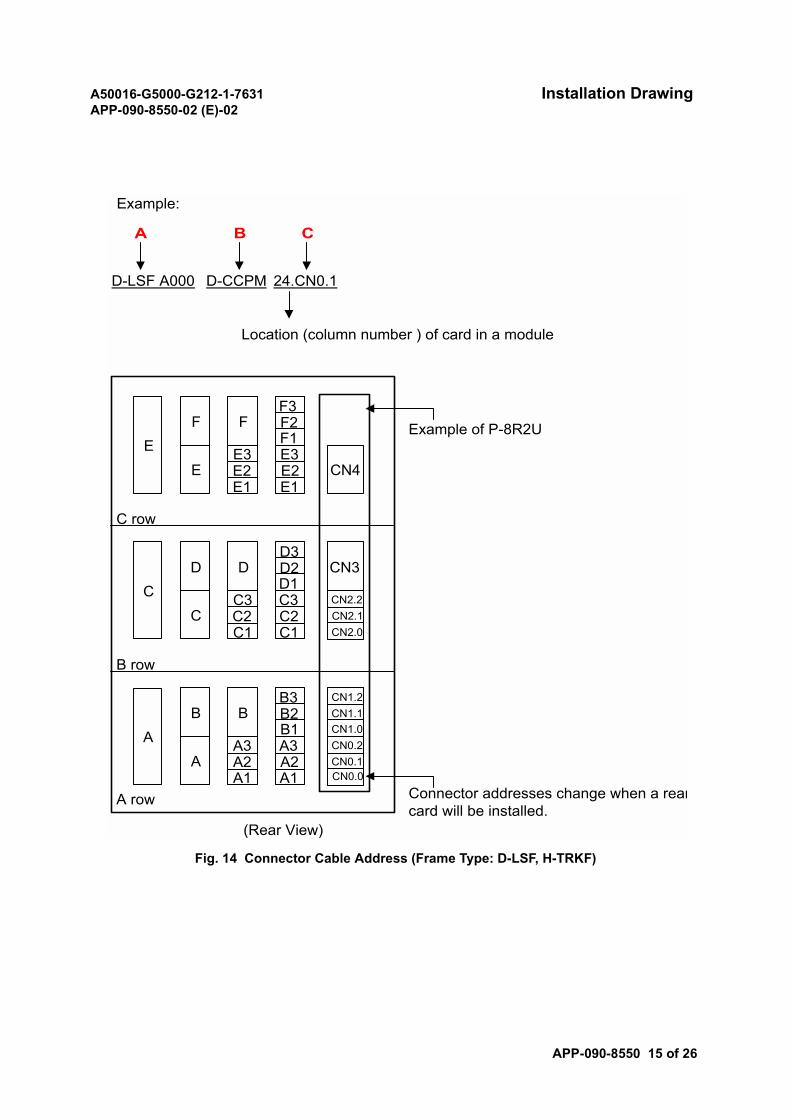
A50016-G5000-G212-1-7631 Installation DrawingAPP-090-8550-02 (E)-02
APP-090-8550 15 of 26
Fig. 14 Connector Cable Address (Frame Type: D-LSF, H-TRKF)
F3F2F1
E3 E3E2 E2E1 E1
C row
D3D2D1
C3 C3 CN2.2C2 C2 CN2.1C1 C1 CN2.0
B row
B3 CN1.2B2 CN1.1B1 CN1.0
A3 A3 CN0.2A2 A2 CN0.1A1 A1 CN0.0
A row
CN3
CN4
F
D
EF
E
B
C
A
D
B
A
C
Example of P-8R2U
(Rear View)
Example:
D-LSF A000 D-CCPM 24.CN0.1
Location (column number ) of card in a module
A B C
Connector addresses change when a rearcard will be installed.
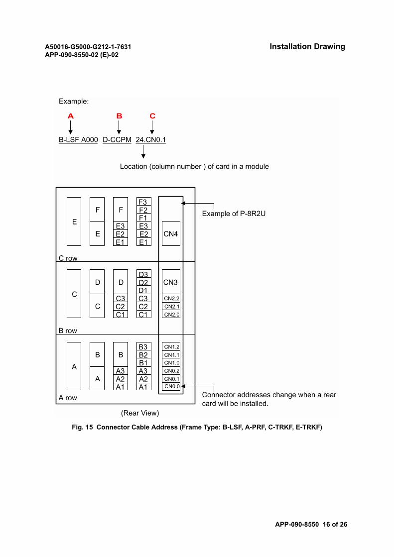
A50016-G5000-G212-1-7631 Installation DrawingAPP-090-8550-02 (E)-02
APP-090-8550 16 of 26
Fig. 15 Connector Cable Address (Frame Type: B-LSF, A-PRF, C-TRKF, E-TRKF)
F3F2F1
E3 E3E2 E2E1 E1
C row
D3D2D1
C3 C3 CN2.2
C2 C2 CN2.1
C1 C1 CN2.0
B row
B3 CN1.2
B2 CN1.1B1 CN1.0
A3 A3 CN0.2
A2 A2 CN0.1A1 A1 CN0.0
A row
CN3
CN4
F
D
EF
E
B
C
A
D
B
A
C
Example of P-8R2U
(Rear View)
Example:
B-LSF A000 D-CCPM 24.CN0.1
Location (column number ) of card in a module
A B C
Connector addresses change when a rearcard will be installed.
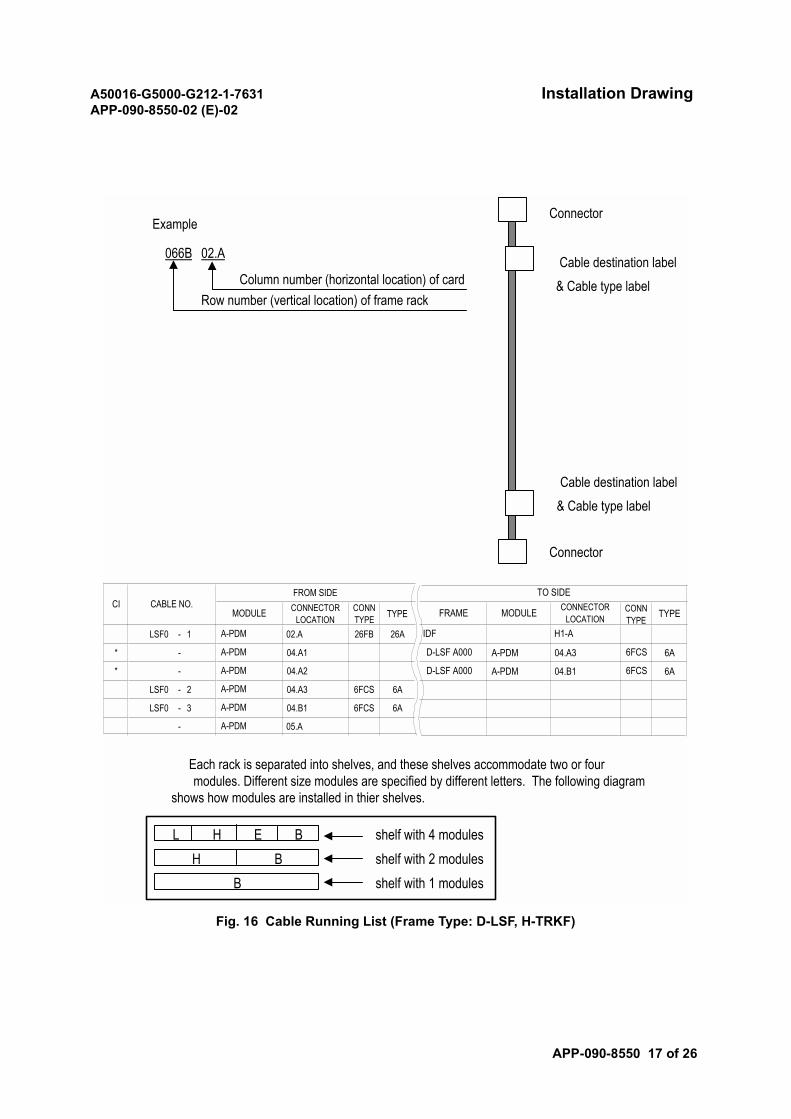
A50016-G5000-G212-1-7631 Installation DrawingAPP-090-8550-02 (E)-02
APP-090-8550 17 of 26
Fig. 16 Cable Running List (Frame Type: D-LSF, H-TRKF)
L H E B shelf with 4 modulesshelf with 2 modulesshelf with 1 modules
H BB
Cable destination label& Cable type label
Connector
Cable destination label& Cable type label
Example
066B 02.A
Column number (horizontal location) of cardRow number (vertical location) of frame rack
Each rack is separated into shelves, and these shelves accommodate two or fourmodules. Different size modules are specified by different letters. The following diagram
shows how modules are installed in thier shelves.
Connector
CONNECTORLOCATION
CONNTYPE TYPE
LSF0 - 1 02.A 26FB 26A
* - 04.A1
* - 04.A2
LSF0 - 2 04.A3 6FCS 6A
LSF0 - 3 04.B1 6FCS 6A
- 05.A
CI CABLE NO.MODULE
FROM SIDE
A-PDM
A-PDM
A-PDM
A-PDM
A-PDM
A-PDM
TYPE
A-PDM 04.A3 6A
A-PDM 04.B1 6A6FCSD-LSF A000
6FCS
H1-AIDF
FRAME MODULE CONNECTORLOCATION
CONNTYPE
TO SIDE
D-LSF A000
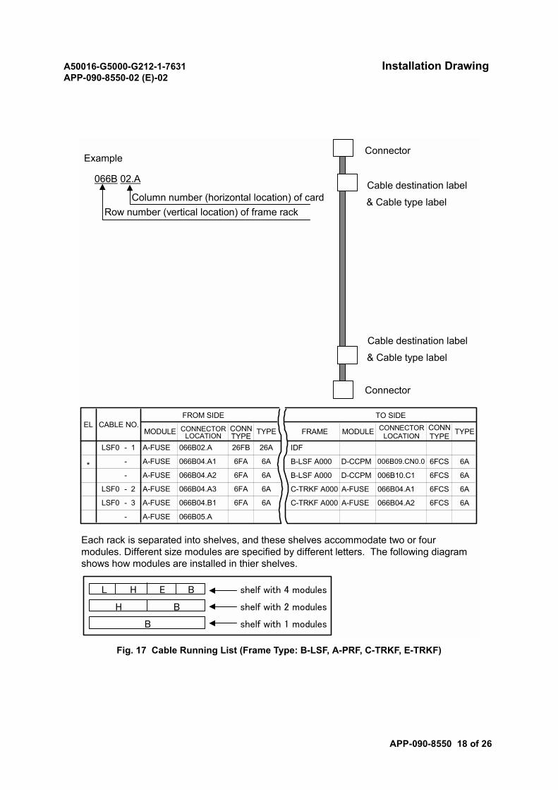
A50016-G5000-G212-1-7631 Installation DrawingAPP-090-8550-02 (E)-02
APP-090-8550 18 of 26
Fig. 17 Cable Running List (Frame Type: B-LSF, A-PRF, C-TRKF, E-TRKF)
L H E B shelf with 4 modules
shelf with 2 modules
shelf with 1 modules
H B
B
Cable destination label
& Cable type label
Connector
Cable destination label
& Cable type label
Example
066B 02.A
Column number (horizontal location) of cardRow number (vertical location) of frame rack
Each rack is separated into shelves, and these shelves accommodate two or fourmodules. Different size modules are specified by different letters. The following diagramshows how modules are installed in thier shelves.
Connector
CABLE NO.FROM SIDE
MODULE CONNECTORLOCATION
CONNTYPE TYPE
A-FUSE 066B02.ALSF0 - 1 26FB 26A
- A-FUSE 066B04.A1 6FA 6A
6FA 6AA-FUSE 066B04.A2-
- 2 A-FUSE 066B04.A3
6A
6FA 6ALSF0
LSF0 - 3 A-FUSE 066B04.B1 6FA
- A-FUSE 066B05.A
A-FUSEC-TRKF A000
066B04.A1
066B04.A2 6A
6FCS 6A
6FCS 6AC-TRKF A000
006B10.C1B-LSF A000 D-CCPM
006B09.CN0.0 6FCS 6AB-LSF A000 D-CCPM
IDF
A-FUSE
6FCS
TO SIDECONNECTOR
LOCATIONCONNTYPE TYPEFRAME MODULE
EL
*

A50016-G5000-G212-1-7631 Installation DrawingAPP-090-8550-02 (E)-02
APP-090-8550 19 of 26
For each alphabet character used in these figures, refer to the following:
A: Frame name
B: Module name
C: Connector address (Details are described in Fig.14 and Fig.15.)
3. CABLE WIRING CHART
3.1 Terminal Box Wiring Chart
The terminal box wiring chart shows the numbers of pair cables connected to terminal blocks on aterminal box.
Fig.18 is a terminal box wiring chart example.
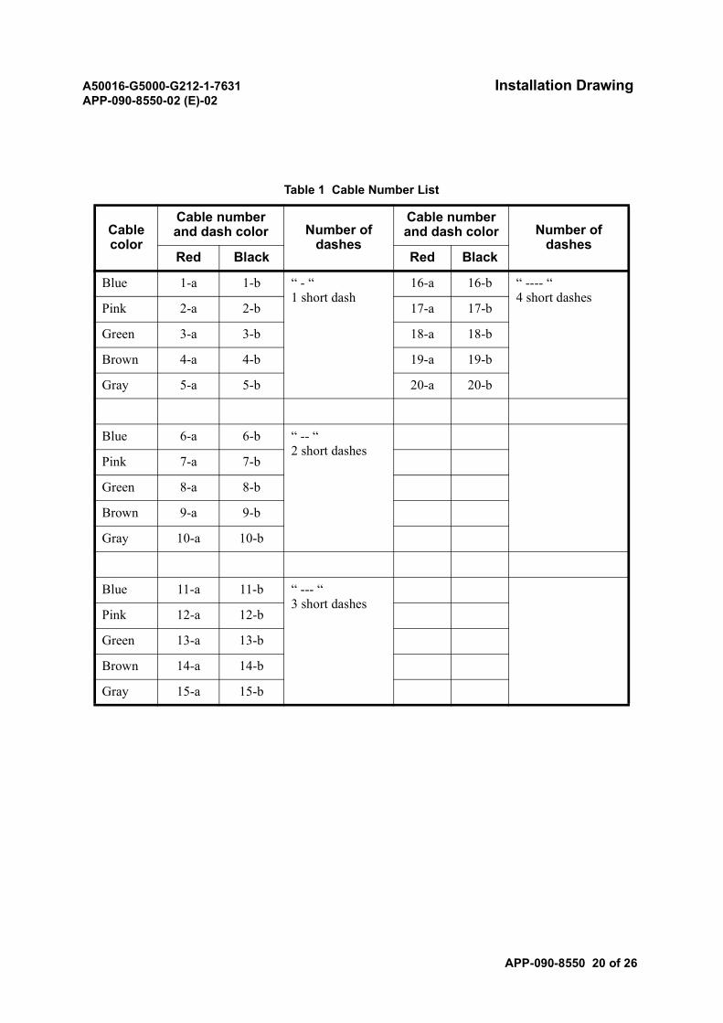
A50016-G5000-G212-1-7631 Installation DrawingAPP-090-8550-02 (E)-02
APP-090-8550 20 of 26
Table 1 Cable Number List
Cable color
Cable number and dash color Number of
dashes
Cable number and dash color Number of
dashesRed Black Red Black
Blue 1-a 1-b “ - “1 short dash
16-a 16-b “ ---- “4 short dashes
Pink 2-a 2-b 17-a 17-b
Green 3-a 3-b 18-a 18-b
Brown 4-a 4-b 19-a 19-b
Gray 5-a 5-b 20-a 20-b
Blue 6-a 6-b “ -- “2 short dashes
Pink 7-a 7-b
Green 8-a 8-b
Brown 9-a 9-b
Gray 10-a 10-b
Blue 11-a 11-b “ --- “3 short dashes
Pink 12-a 12-b
Green 13-a 13-b
Brown 14-a 14-b
Gray 15-a 15-b
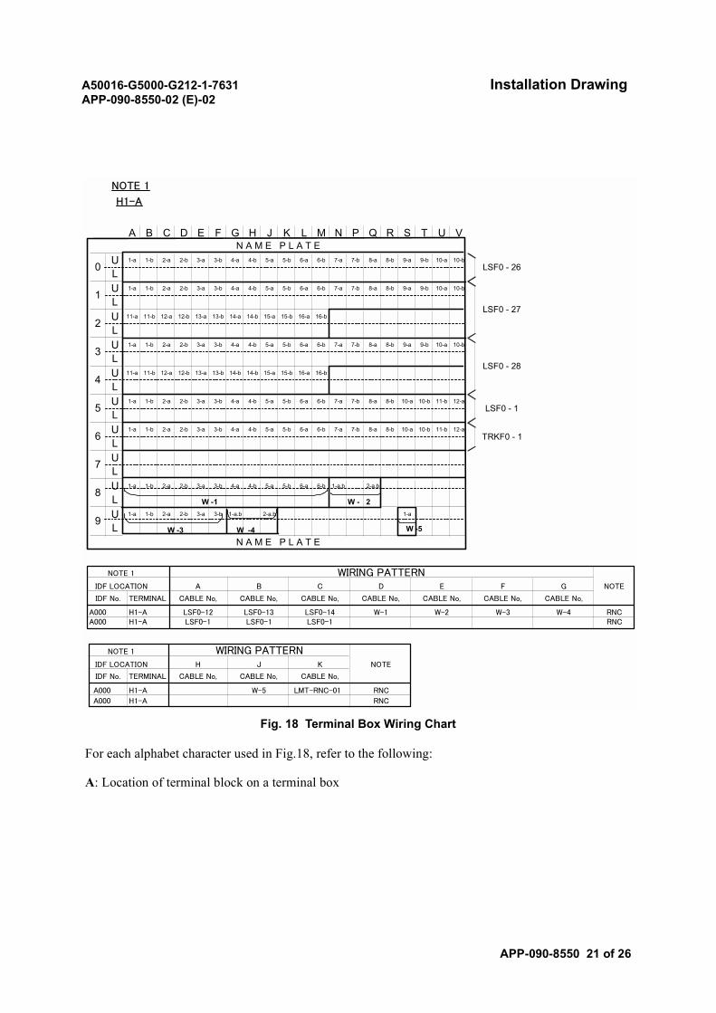
A50016-G5000-G212-1-7631 Installation DrawingAPP-090-8550-02 (E)-02
APP-090-8550 21 of 26
Fig. 18 Terminal Box Wiring Chart
For each alphabet character used in Fig.18, refer to the following:
A: Location of terminal block on a terminal box
NOTE 1
H1-A
LSF0 - 26
LSF0 - 27
LSF0 - 28
LSF0 - 1
0
N A M E P L A T E
N A M E P L A T E
TRKF0 - 1
8L
9L
U
U
3 L
4L
1L
2L
UL
L
L
U
U
U
U
1-a1-a.b 2-a.b1-a 1-b 2-a 2-b 3-a 3-b
4-b 5-a 5-b 6-a3-a 3-b 6-b 1-a.b 2-a.b1-a 1-b 2-a 2-b 4-a
7 LU
12-a8-b 10-a 10-b 11-b6-b 7-a 7-b 8-a4-b 5-a 5-b 6-a2-b 3-a 3-b 4-a1-a 1-b 2-aU6
12-a8-b 10-a 10-b 11-b6-b 7-a 7-b 8-a4-b 5-a 5-b 6-a2-b 3-a 3-b 4-a5
1-a 1-b 2-aU
15-a 15-b 16-a 16-b
10-b
11-a 11-b 12-a 12-b 13-a 13-b 14-b 14-b
8-b 9-a 9-b 10-a6-b 7-a 7-b 8-a4-b 5-a 5-b 6-a1-a 1-b 2-a 2-b 3-a 3-b 4-a
16-a 16-b14-a 14-b 15-a 15-b
10-a 10-b
11-a 11-b 12-a 12-b 13-a 13-b
8-a 8-b 9-a 9-b6-a 6-b 7-a 7-b4-a 4-b 5-a 5-b
10-b
1-a 1-b 2-a 2-b 3-a 3-b
8-b 9-a 9-b 10-a6-b 7-a 7-b 8-a4-b 5-a 5-b 6-a1-a 1-b 2-a 2-b 3-a 3-b 4-a
SJ K L ME F T U VN P Q RG HA B C D
W -1 W - 2
W -3 W -4 W -5
NOTE 1 WIRING PATTERNIDF LOCATION A B C D E F G NOTE
IDF No. TERMINAL CABLE No, CABLE No, CABLE No, CABLE No, CABLE No, CABLE No, CABLE No,
A000 H1-A LSF0-12 LSF0-13 LSF0-14 W-1 W-2 W-3 W-4 RNCA000 H1-A LSF0-1 LSF0-1 LSF0-1 RNC
NOTE 1 WIRING PATTERNIDF LOCATION H J K NOTE
IDF No. TERMINAL CABLE No, CABLE No, CABLE No,
A000 H1-A W-5 LMT-RNC-01 RNC
A000 H1-A RNC
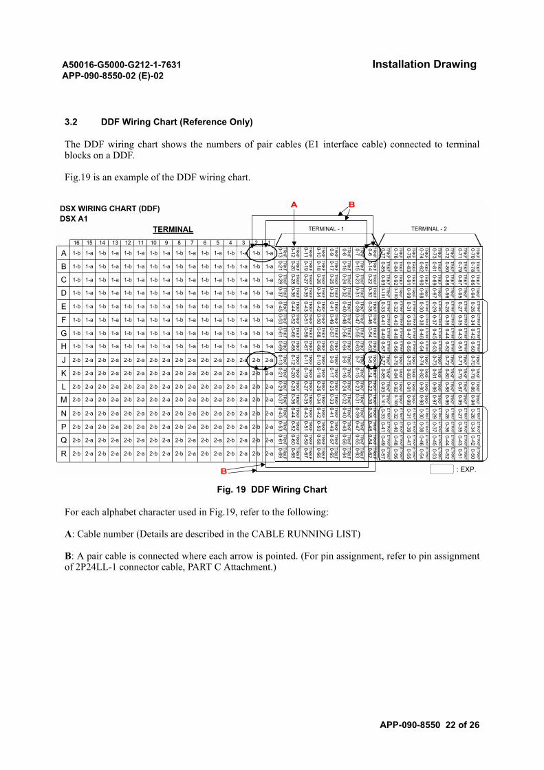
A50016-G5000-G212-1-7631 Installation DrawingAPP-090-8550-02 (E)-02
APP-090-8550 22 of 26
3.2 DDF Wiring Chart (Reference Only)
The DDF wiring chart shows the numbers of pair cables (E1 interface cable) connected to terminalblocks on a DDF.
Fig.19 is an example of the DDF wiring chart.
Fig. 19 DDF Wiring Chart
For each alphabet character used in Fig.19, refer to the following:
A: Cable number (Details are described in the CABLE RUNNING LIST)
B: A pair cable is connected where each arrow is pointed. (For pin assignment, refer to pin assignmentof 2P24LL-1 connector cable, PART C Attachment.)
DSX WIRING CHART (DDF)DSX A1
TERMINAL TERMINAL - 1 TERMINAL - 2
16 15 14 13 12 11 10 9 8 7 6 5 4 3 2 1
A 1-b 1-a 1-b 1-a 1-b 1-a 1-b 1-a 1-b 1-a 1-b 1-a 1-b 1-a 1-b 1-aTR
KF
TRKF
TRKF
TRKF
TRKF
TRKF
TRKF
TRKF
B 1-b 1-a 1-b 1-a 1-b 1-a 1-b 1-a 1-b 1-a 1-b 1-a 1-b 1-a 1-b 1-aTR
KF
TRKF
TRKF
TRKF
TRKF
TRKF
TRKF
TRKF
C 1-b 1-a 1-b 1-a 1-b 1-a 1-b 1-a 1-b 1-a 1-b 1-a 1-b 1-a 1-b 1-a
TRKF
TRKF
TRKF
TRKF
TRKF
TRKF
TRKF
TRKF
D 1-b 1-a 1-b 1-a 1-b 1-a 1-b 1-a 1-b 1-a 1-b 1-a 1-b 1-a 1-b 1-a
TRKF
TRKF
TRKF
TRKF
TRKF
TRKF
TRKF
TRKF
E 1-b 1-a 1-b 1-a 1-b 1-a 1-b 1-a 1-b 1-a 1-b 1-a 1-b 1-a 1-b 1-a
F 1-b 1-a 1-b 1-a 1-b 1-a 1-b 1-a 1-b 1-a 1-b 1-a 1-b 1-a 1-b 1-a
TRKF
TRKF
TRKF
TRKF
TRKF
TRKF
TRKF
TRKF
G 1-b 1-a 1-b 1-a 1-b 1-a 1-b 1-a 1-b 1-a 1-b 1-a 1-b 1-a 1-b 1-a
TRKF
TRKF
TRKF
TRKF
TRKF
TRKF
TRKF
TRKF
H 1-b 1-a 1-b 1-a 1-b 1-a 1-b 1-a 1-b 1-a 1-b 1-a 1-b 1-a 1-b 1-a
TRKF
TRKF
TRKF
TRKF
TRKF
TRKF
TRKF
TRKF
J 2-b 2-a 2-b 2-a 2-b 2-a 2-b 2-a 2-b 2-a 2-b 2-a 2-b 2-a 2-b 2-a
K 2-b 2-a 2-b 2-a 2-b 2-a 2-b 2-a 2-b 2-a 2-b 2-a 2-b 2-a 2-b 2-a
TRKF
TRKF
TRKF
TRKF
TRKF
TRKF
TRKF
TRKF
L 2-b 2-a 2-b 2-a 2-b 2-a 2-b 2-a 2-b 2-a 2-b 2-a 2-b 2-a 2-b 2-a
TRKF
TRKF
TRKF
TRKF
TRKF
TRKF
TRKF
TRKF
M 2-b 2-a 2-b 2-a 2-b 2-a 2-b 2-a 2-b 2-a 2-b 2-a 2-b 2-a 2-b 2-a
TRKF
TRKF
TRKF
TRKF
TRKF
TRKF
TRKF
TRKF
N 2-b 2-a 2-b 2-a 2-b 2-a 2-b 2-a 2-b 2-a 2-b 2-a 2-b 2-a 2-b 2-a
TRKF
TRKF
TRKF
TRKF
TRKF
TRKF
TRKF
TRKF
P 2-b 2-a 2-b 2-a 2-b 2-a 2-b 2-a 2-b 2-a 2-b 2-a 2-b 2-a 2-b 2-a
TRKF
TRKF
TRKF
TRKF
TRKF
TRKF
TRKF
TRKF
Q 2-b 2-a 2-b 2-a 2-b 2-a 2-b 2-a 2-b 2-a 2-b 2-a 2-b 2-a 2-b 2-a
TRKF
TRKF
TRKF
TRKF
TRKF
TRKF
TRKF
TRKF
R 2-b 2-a 2-b 2-a 2-b 2-a 2-b 2-a 2-b 2-a 2-b 2-a 2-b 2-a 2-b 2-a
TRK
F
TRK
F
TRK
F
TRK
F
TRK
F
TRK
F
TRK
F
TRK
F
: EXP.
0-13
0-12
0-11
0-10
0-9
0-8
0-7
0-6
0-21
0-20
0-19
0-18
0-17
0-16
0-15
0-14
0-29
0-28
0-27
0-26
0-25
0-24
0-23
0-22
0-37
0-36
0-35
0-34
0-33
0-32
0-31
0-30
0-53
0-52
0-51
0-50
0-49
0-48
0-47
0-46
0-61
0-60
0-59
0-58
0-57
0-56
0-55
0-54
0-9
0-8
0-7
0-6
0-21
0-20
0-19
0-18
0-17
0-16
0-15
0-14
0-29
0-28
0-27
0-26
0-25
0-24
0-23
0-22
0-37
0-36
0-35
0-34
0-33
0-32
0-31
0-30
0-45
0-44
0-43
0-42
0-41
0-40
0-39
0-38
0-53
0-52
0-51
0-50
0-49
0-48
0-47
0-46
0-61
0-60
0-59
0-58
0-57
0-56
0-55
0-54
0-69
0-68
0-67
0-66
0-65
0-64
0-63
0-62
0-77
0-76
0-75
0-74
0-73
0-72
0-71
0-70
0-85
0-84
0-83
0-82
0-81
0-80
0-79
0-78
0-93
0-92
0-91
0-90
0-89
0-88
0-87
0-86
0-101
0-100
0-99
0-98
0-97
0-96
0-95
0-94
0-33
0-32
0-31
0-30
0-29
0-28
0-27
0-26
0-41
0-40
0-39
0-38
0-37
0-36
0-35
0-34
0-49
0-48
0-47
0-46
0-45
0-44
0-43
0-42
0-57
0-56
0-55
0-54
0-53
0-52
0-51
0-50
TRKF
TRKF
TRKF
TRKF
TRKF
TRKF
TRKF
TRKF
TRKF
TRKF
TRKF
TRKF
TRKF
TRKF
TRKF
TRKF
TRKF
TRKF
TRKF
TRKF
TRKF
TRKF
TRKF
TRKF
TRKF
TRKF
TRKF
TRKF
TRKF
TRKF
TRKF
TRKF
ETRKF
ETRKF
ETRKF
ETRKF
ETRKF
ETRKF
ETRKF
ETRKF
ETRKF
ETRKF
ETRKF
ETRKF
ETRKF
ETRKF
ETRKF
ETRKF
ETRKF
ETRKF
ETRKF
ETRKF
ETRKF
ETRKF
ETRKF
ETRKF
ETRKF
ETRKF
ETRKF
ETRKF
ETRKF
ETRKF
ETRKF
ETRKF
TRKF
TRKF
TRKF
TRKF
TRKF
TRKF
TRKF
TRKF
TRKF
TRKF
TRKF
TRKF
TRKF
TRKF
TRKF
TRKF
TRKF
TRKF
TRKF
TRKF
TRKF
TRKF
TRKF
TRKF
TRKF
TRKF
TRKF
TRKF
TRKF
TRKF
TRKF
TRKF
ETRKF
ETRKF
ETRKF
ETRKF
ETRKF
ETRKF
ETRKF
ETRKF
ETRKF
ETRKF
ETRKF
ETRKF
ETRKF
ETRKF
ETRKF
ETRKF
ETRKF
ETRKF
ETRKF
ETRKF
ETRKF
ETRKF
ETRKF
ETRKF
ETR
KF
ETR
KF
ETR
KF
ETR
KF
ETR
KF
ETR
KF
ETR
KF
ETR
KF
TRKF
TRKF
TRKF
TRKF
TRKF
TRKF
TRKF
TRKF
0-45
0-44
0-43
0-42
0-41
0-40
0-39
0-38
TRKF
TRKF
TRKF
TRKF
TRKF
TRKF
TRKF
TRKF
0-69
0-68
0-67
0-66
0-65
0-64
0-63
0-62
0-13
0-12
0-11
0-10
B
BA

A50016-G5000-G212-1-7631 Installation DrawingAPP-090-8550-02 (E)-02
APP-090-8550 23 of 26
4. JUMPER LIST
4.1 IDF Wiring List
4.1.1 Outline
The IDF accommodates terminals connected to the miscellaneous, alarm and test leads.
The IDF jumper wiring list shows jumper wirings between the terminal block pins on the terminal boxfor the interconnection of cables coming from various equipment.
4.1.2 How to read a IDF jumper wiring list
Fig.20 and Fig.21 are example of the IDF jumper wiring list.
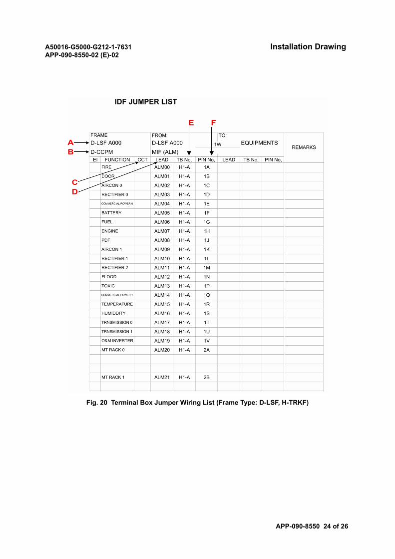
A50016-G5000-G212-1-7631 Installation DrawingAPP-090-8550-02 (E)-02
APP-090-8550 24 of 26
Fig. 20 Terminal Box Jumper Wiring List (Frame Type: D-LSF, H-TRKF)
IDF JUMPER LIST
AB
CD
E F
MT RACK 1 ALM21 H1-A 2B
MT RACK 0 ALM20 H1-A 2A
O&M INVERTER ALM19 H1-A 1V
TRNSMISSION 1 ALM18 H1-A 1U
TRNSMISSION 0 ALM17 H1-A 1T
HUMIDDITY ALM16 H1-A 1S
TEMPERATURE ALM15 H1-A 1R
COMMERCIAL POWER 1 ALM14 H1-A 1Q
TOXIC ALM13 H1-A 1P
FLOOD ALM12 H1-A 1N
RECTIFIER 2 ALM11 H1-A 1M
RECTIFIER 1 ALM10 H1-A 1L
AIRCON 1 ALM09 H1-A 1K
PDF ALM08 H1-A 1J
ENGINE ALM07 H1-A 1H
FUEL ALM06 H1-A 1G
BATTERY ALM05 H1-A 1F
COMMERCIAL POWER 0 ALM04 H1-A 1E
RECTIFIER 0 ALM03 H1-A 1D
H1-A 1CAIRCON 0 ALM02
DOOR ALM01
PIN No,FIRE ALM00 H1-A 1A
TB No, PIN No, LEAD TB No,EI FUNCTION CCT LEADD-CCPM MIF (ALM)
H1-A 1B
TO:D-LSF A000 D-LSF A000 EQUIPMENTS1W REMARKS
FRAME FROM:
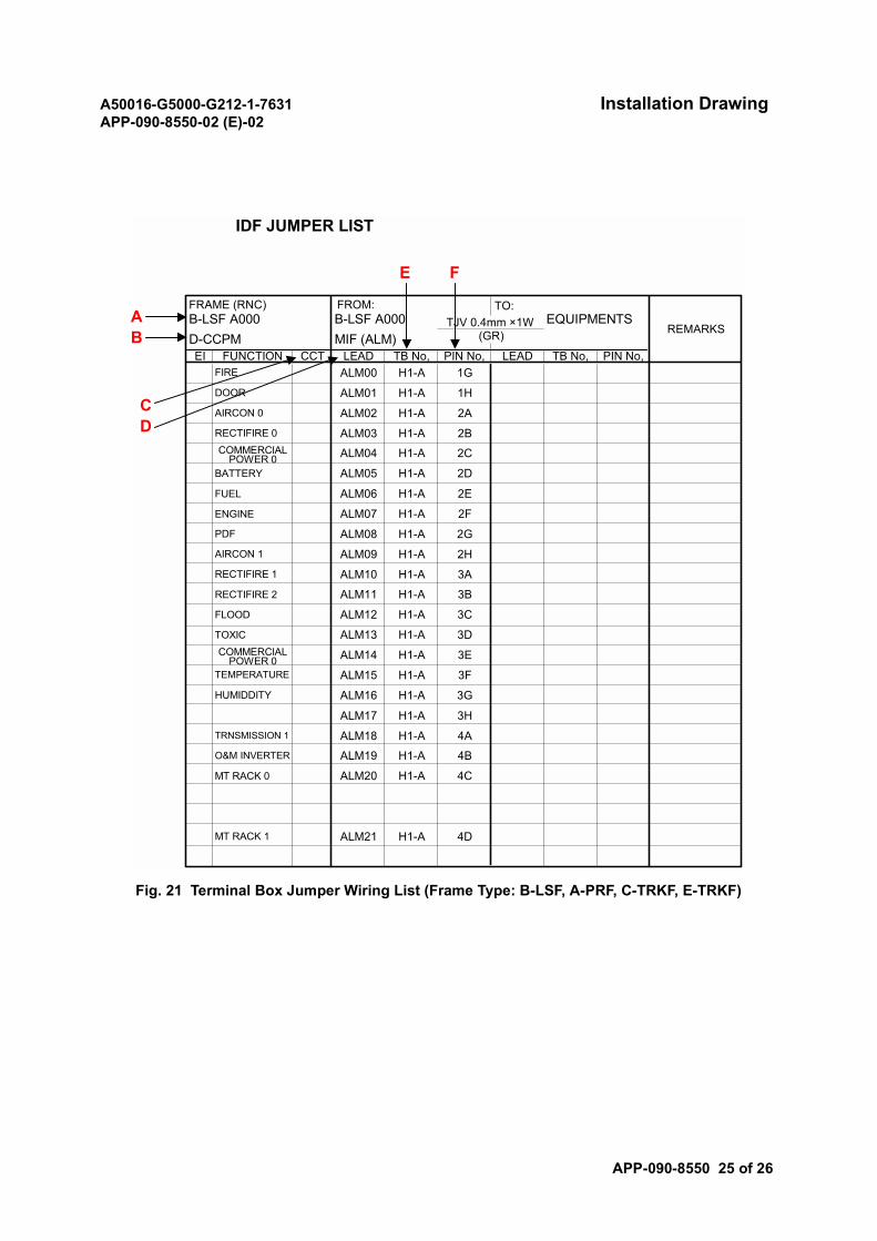
A50016-G5000-G212-1-7631 Installation DrawingAPP-090-8550-02 (E)-02
APP-090-8550 25 of 26
Fig. 21 Terminal Box Jumper Wiring List (Frame Type: B-LSF, A-PRF, C-TRKF, E-TRKF)
IDF JUMPER LIST
FRAME (RNC) FROM: TO:
REMARKSD-CCPM MIF (ALM) (GR)B-LSF A000 B-LSF A000 EQUIPMENTSTJV 0.4mm ×1W
EI FUNCTION CCT LEAD TB No, PIN No, LEAD TB No, PIN No,FIRE ALM00 H1-A 1G
DOOR ALM01 H1-A 1H
AIRCON 0 ALM02 H1-A 2A
RECTIFIRE 0 ALM03 H1-A 2BCOMMERCIAL
POWER 0 ALM04 H1-A 2C
BATTERY ALM05 H1-A 2D
FUEL ALM06 H1-A 2E
ENGINE ALM07 H1-A 2F
PDF ALM08 H1-A 2G
AIRCON 1 ALM09 H1-A 2H
RECTIFIRE 1 ALM10 H1-A 3A
RECTIFIRE 2 ALM11 H1-A 3B
FLOOD ALM12 H1-A 3C
TOXIC ALM13 H1-A 3D
ALM14 H1-A 3ETEMPERATURE ALM15 H1-A 3F
HUMIDDITY ALM16 H1-A 3G
ALM17 H1-A 3HTRNSMISSION 1 ALM18 H1-A 4AO&M INVERTER ALM19 H1-A 4B
MT RACK 0 ALM20 H1-A 4C
MT RACK 1 ALM21 H1-A 4D
COMMERCIALPOWER 0
AB
CD
E F

A50016-G5000-G212-1-7631 Installation DrawingAPP-090-8550-02 (E)-02
APP-090-8550 26 of 26
For each alphabet character used in Fig.20 and Fig.21, refer to the following:
A: Frame name
B: Module name (Card name (function name))
C: Circuit
D: Lead name
E: Terminal block number
F: Pin number
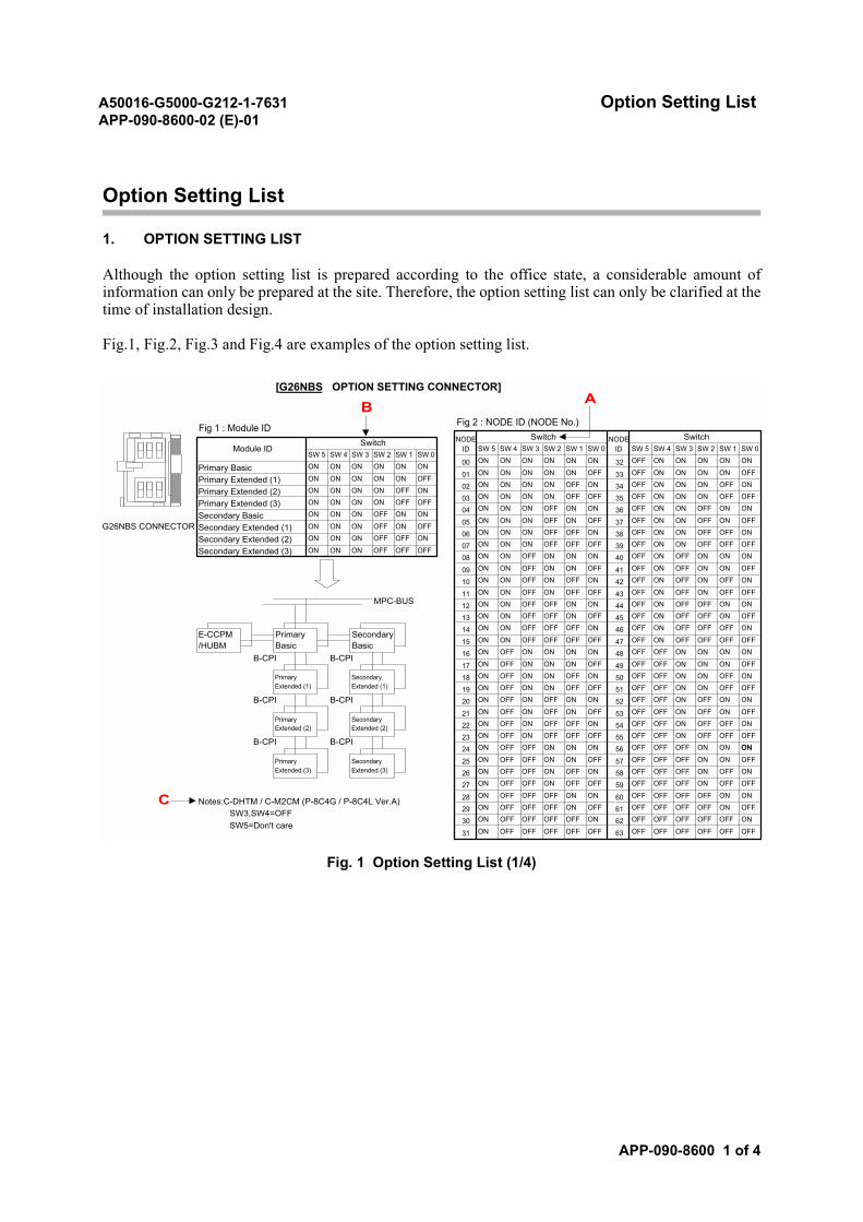
A50016-G5000-G212-1-7631 Option Setting ListAPP-090-8600-02 (E)-01
APP-090-8600 1 of 4
Option Setting List
1. OPTION SETTING LIST
Although the option setting list is prepared according to the office state, a considerable amount ofinformation can only be prepared at the site. Therefore, the option setting list can only be clarified at thetime of installation design.
Fig.1, Fig.2, Fig.3 and Fig.4 are examples of the option setting list.
Fig. 1 Option Setting List (1/4)
OFF OFF OFF63 OFF OFF OFFOFF OFF OFF OFF SW5=Don't care
31 ON OFF
OFF OFF OFF ONON 62 OFF OFFOFF ON OFF
SW3,SW4=OFF30 ON OFF OFF OFF OFF
61 OFF OFF OFFON ON
Notes:C-DHTM / C-M2CM (P-8C4G / P-8C4L Ver.A)29 ON OFF OFF OFF ON OFF
OFF OFF OFF OFF
OFF OFF
28 ON OFF OFF OFF ON ON 60
OFF OFF OFF ONON OFF OFF 5927 ON OFF OFFOFF ON OFF ONON 58 OFF OFFOFF OFF ON OFFOFF ON ON OFFOFF 57 OFF OFFOFF OFF ON ONPrimary
Extended (3)SecondaryExtended (3)
25 ON
26 ON
OFF ON ON ONON 56 OFF OFFOFF OFF
B-CPI B-CPI24 ON OFF OFF ON ON
OFF OFF ON OFFOFF OFF OFF 5523 ON OFF ONON OFF OFF ONON 54 OFF OFF
ON OFFPrimaryExtended (2)
SecondaryExtended (2) 22 ON OFF ON OFF OFF
OFF OFF ON OFFOFF ON OFF 5321 ON OFF ON
ON OFF ON ONON 52 OFF OFFOFF ON OFF ONB-CPI B-CPI 20 ONON ON OFF OFFOFF 51 OFF OFFOFF ON ON OFFON ON OFF ONON 50 OFF OFFOFF ON ON OFFPrimary
Extended (1)SecondaryExtended (1)
18 ON
19 ON
ON ON ON OFFOFF 49 OFF OFF
ON ONB-CPI B-CPI
17 ON OFF ON ON ON
OFF OFF ON ONOFF OFF
16 ON OFF ON ON ON ON 48
OFF ON OFF OFFOFF OFF OFF 47
OFF OFF ONE-CCPM/HUBM
PrimaryBasic
SecondaryBasic 15 ON ON OFF
46 OFF ON OFFOFF ON OFF
14 ON ON OFF OFF OFF ON45 OFF ON OFF
ON ON
13 ON ON OFF OFF ON OFFOFF ON OFF OFF
OFFMPC-BUS 12 ON ON OFF OFF ON ON 44
ON OFF ON OFF
ON
11 ON ON OFF ON OFF OFF 43 OFF
ON OFF ON OFFOFF
10 ON ON OFF ON OFF ON 42 OFFON OFF ON ON
ON
09 ON ON OFF ON ON OFF 41 OFF
ON OFF ON ONON ON 40 OFFON ON OFF ONOFF OFF OFF
08Secondary Extended (3) ON ON ON
ON OFF OFF OFFOFF 39 OFF ONON ON OFF OFFON
Secondary Extended (2) ON ON ON OFF OFF ON07 ON
ON ON OFF OFFOFF ON 38 OFFON ON ON OFFOFF ON OFF
06Secondary Extended (1) ON ON ON
ON OFF ON OFFOFF 37 OFF ONSecondary Basic ON ON ONON
OFF ON ON05 ON ON ON OFF ON
ON ON OFF ONON ON 36 OFFON ON ON OFFON OFF OFF
04Primary Extended (3) ON ON ON
ON ON OFF OFFOFF 35 OFF ONON ON ON OFFON
Primary Extended (2) ON ON ON ON OFF ON03 ON
ON ON ON OFFOFF ON 34 OFFON ON ON ONON ON OFF
02Primary Extended (1) ON ON ON
ON ON ON OFFOFF 33 OFF ONON ON ON ON
ONPrimary Basic ON ON ON ON ON ON
01 ON
ON ON ON ONON ON 32 OFFSW 1 SW 0
SW 5 SW 4 SW 3 SW 2 SW 1 SW 000 ON
SW 5 SW 4 SW 3 SW 2Switch
Module IDSwitch
SW 5 SW 4 SW 3 SW 2 SW 1 SW 0
[G26NBS OPTION SETTING CONNECTOR]
G26NBS CONNECTOR
Fig 2 : NODE ID (NODE No.)Fig 1 : Module IDNODE
IDSwitch
ON ON ON
NODEID
B A
C
ON
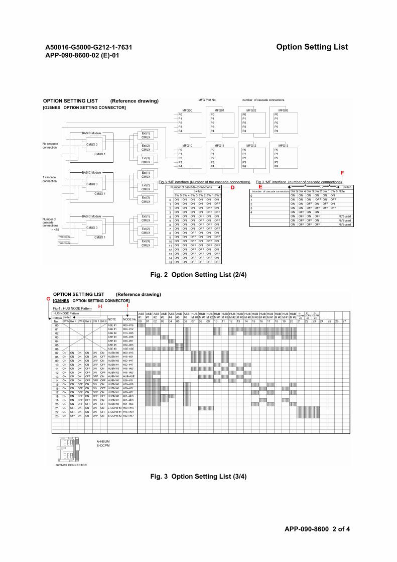
A50016-G5000-G212-1-7631 Option Setting ListAPP-090-8600-02 (E)-01
APP-090-8600 2 of 4
Fig. 2 Option Setting List (2/4)
Fig. 3 Option Setting List (3/4)
OFFONOFFOFFON
ON
2 ONOFFONON
OFF OFF ON
15 ON ON OFF OFF OFF OFF14 ON ON OFF
OFF ON ON
13 ON ON OFF OFF ON OFF12 ON ON OFF
OFFTER CONN
11 ON ON OFF ON OFFOFF ON OFF ONExt(3)
CMUX10 ON ON
OFFON OFF ON ONTER CONN CMUX 1 9 ONOFF ON ON ONON OFF OFF OFF
OFF No't usedON OFF OFFON OFF OFF ONON ONExt(2)CMUX
7 ON ON
8 ON ON
ON No't usedON OFF OFFNo't used
5 ON ON ON OFF ON OFFONON
ON OFF
ON ONON OFF
ON ON OFF
No cascadeconnection
n <15
Ext(2)CMUX
CMUX 06
Ext(1)CMUX
4 ON3 ON ON ON
OFF OFFOFF 4 ONON
ON ON OFF OFFON 32 ON ON ONOFF1 ON ON ON OFF ON
ON1 ON ONONON ON
OFF ON OFFON
Ext(3)CMUX 0 ON ON ON ON ON ON
ONSW 1 SW 0SW 3 SW 2SW 4SW 5Number of cascade connections
0 ONCMUX 1 SW 5 SW 4 SW 3SW 1 SW 0
Fig 3 :MF interface (Number of the cascade connections) Fig 3 :MF interface (number of cascade connections)Number of cascade connections Switch
Switch NoteSW 2
P3
Ext(1)CMUX
CMUX 0
Ext(3)CMUX
P2CMUX 1 P1 P1 P1
P0 P0P1P2P3
P4 P4
P2
P0 P0
P4 P4
P2P3 P3
MFG10 MFG11 MFG12 MFG13
Ext(1)CMUX
CMUX 0 Ext(2)CMUX
P4 P4 P4 P4
P0 P0P1 P1P2 P2P3 P3
P0 P0P1 P1P2 P2P3 P3
MFG00 MFG01 MFG02 MFG03
OPTION SETTING LIST (Reference drawing)[G26NBS OPTION SETTING CONNECTOR]
MFG Port No. number of cascade connections
BASIC Module
BASIC Module
BASIC Module
D E
F1 cascadeconnection
Number ofcascadeconnections
OPTION SETTING LIST (Reference drawing)[G26NBS OPTION SETTING CONNECTOR]
Fig 4 : HUB NODE PatternHUB NODE Pattern ASE
#1ASE#1
ASE#2
ASE#3
ASE#4
ASE#5
ASE#0
HUBM #0
HUBM #1
HUBM #2
HUBM #1
HUBM #3
HUBM #2
HUBM #0
HUBM #0
HUBM #0
HUBM #0
HUBM #1
HUBM #0
HUBM #1
HUBM #2
E-CCPM
#0 #1 #2PatternNo.
SwitchNOTE NODE No.
SW 5 SW 4 SW 3 SW 2 SW 1 SW 0 00 01 02 03 04 05 06 07 08 09 10 11 12 13 14 15 16 17 18 19 20 21 22 23 24 25 26 27ASE #1 #00--#16ASE #1 #00--#12ASE #2 #13--#25ASE #3 #26--#38ASE #4 #39--#51ASE #5 #52--#63ASE #0 ASE-ASE
ON ON ON ON ON ON HUBM #0 #00--#15ON ON ON ON ON OFF HUBM #1 #16--#31ON ON ON ON OFF ON HUBM #2 #32--#47ON ON ON ON OFF OFF HUBM #1 #32--#47ON ON ON OFF ON ON HUBM #3 #48--#63ON ON ON OFF ON OFF HUBM #2 #48--#63ON ON ON OFF OFF ON HUBM #0 HUB-ASEON ON ON OFF OFF OFF HUBM #0 #26--#31ON ON OFF ON ON ON HUBM #0 #26--#38ON ON OFF ON ON OFF HUBM #0 #39--#51ON ON OFF ON OFF ON HUBM #1 #39--#51ON ON OFF ON OFF OFF HUBM #0 #51--#63ON ON OFF OFF ON ON HUBM #1 #51--#63ON ON OFF OFF ON OFF HUBM #2 #51--#63ON OFF ON ON ON ON E-CCPM #0 #00 / #15ON OFF ON ON ON OFF E-CCPM #1 #16 / #31ON OFF ON ON OFF ON E-CCPM #2 #32 / #47
G26NBS CONNECTOR
A-HBUME-CCPM
000102030405060708091011121314151617181920212223
E-CCPM
E-CCPM
IHG
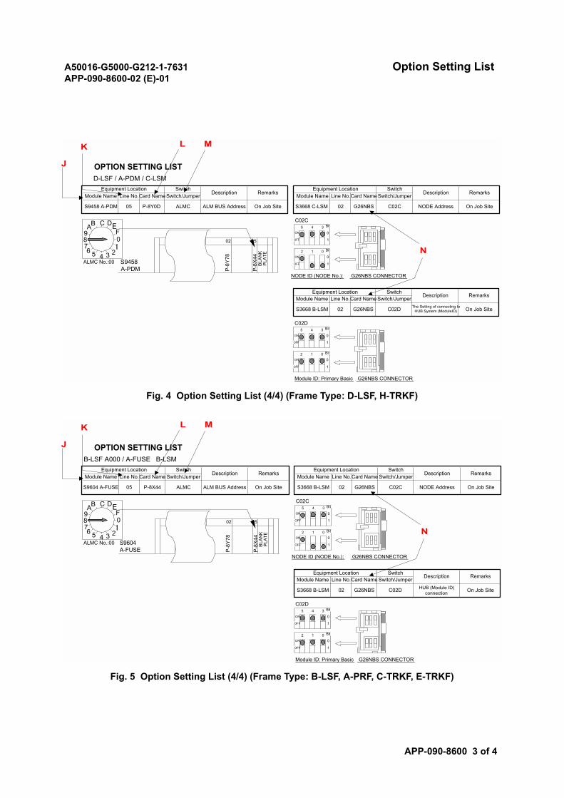
A50016-G5000-G212-1-7631 Option Setting ListAPP-090-8600-02 (E)-01
APP-090-8600 3 of 4
Fig. 4 Option Setting List (4/4) (Frame Type: D-LSF, H-TRKF)
Fig. 5 Option Setting List (4/4) (Frame Type: B-LSF, A-PRF, C-TRKF, E-TRKF)
Bit
ON 0
OFF 1
Bit
ON 0
OFF 1
Bit
ON 0
OFF 1
Bit
ON 0
OFF 1
G26NBS CONNECTORModule ID: Primary Basic
2 1 0
The Setting of connecting toHUB System (ModuleID) On Job Site
C02D5 4 3
S3668 B-LSM 02 G26NBS C02D
Description RemarksModule Name Line No.Card Name Switch/Jumper
NODE ID (NODE No.): G26NBS CONNECTOR
Equipment Location Switch
ALMC No.:00 S9458A-PDM P
-8X
44B
LAN
KP
LATE
2 1
P-8
Y78
0
02 05
C02C5 4 3
G26NBS C02C NODE Address On Job SiteALM BUS Address On Job Site S3668 C-LSM 02S9458 A-PDM 05 P-8Y0D ALMC
RemarksModule Name Line No.Card Name Switch/Jumper Module Name Line No.Card Name Switch/JumperRemarksEquipment Location Switch
Description
OPTION SETTING LISTD-LSF / A-PDM / C-LSM
Equipment Location SwitchDescription
01
23456789AB C DE
F
N
L MK
J
Bit
ON 0
OFF 1
Bit
ON 0
OFF 1
Bit
ON 0
OFF 1
Bit
ON 0
OFF 1
G26NBS CONNECTORModule ID: Primary Basic
2 1 0
HUB (Module ID)connection On Job Site
C02D5 4 3
S3668 B-LSM 02 G26NBS C02D
Description RemarksModule Name Line No.Card Name Switch/Jumper
NODE ID (NODE No.): G26NBS CONNECTOR
Equipment Location Switch
ALMC No.:00 S9604A-FUSE P
-8X
44B
LAN
KP
LATE
2 1
P-8
Y78
0
02 05
C02C5 4 3
G26NBS C02C NODE Address On Job SiteALM BUS Address On Job Site S3668 B-LSM 02S9604 A-FUSE 05 P-8X44 ALMC
RemarksModule Name Line No.Card Name Switch/Jumper Module Name Line No.Card Name Switch/JumperRemarksEquipment Location Switch
Description
OPTION SETTING LISTB-LSF A000 / A-FUSE B-LSM
Equipment Location SwitchDescription
01
23456789AB C DE
F
N
L MK
J

A50016-G5000-G212-1-7631 Option Setting ListAPP-090-8600-02 (E)-01
APP-090-8600 4 of 4
For each alphabet character used in these figures, refer to the following:
A: case of Node ID (sw*_on=0, sw0_off=1, sw1_off=2, sw2_off=4, sw3_off=8, sw4_off=16,sw5_off=32)
B: case of Module ID (sw*_on=0,sw0_off=1, sw1_off=2, sw2_off=4 sw3,4,5=It is always ON.(But, itexcludes C case.))
C: case of C-DHTM and C-M2CM Module ID (sw3,sw4=OFF, sw5=Don’t Care)
D: Number of cascade connection hubs (0 to 15)(sw*_on=0,sw0_off=1, sw1_off=2, sw2_off=4,sw3_off=8)
E: MF port number (most significant 4 bits)(sw*_on=0,sw2_off=1, sw3_off=2, sw4_off=4, sw5_off=8)
F: MF Clock, Number of cascade connection hubs (sw*_on=0, sw0_off=1, sw1_off=2)
G: Hub node pattern number
H: Switch
I: Node number
J: Module name
K: Line number
L: Card name
M: Switch/jumper (N: Ex. C02C consisting of C02: location (column number) of card in a module andC: connector address)
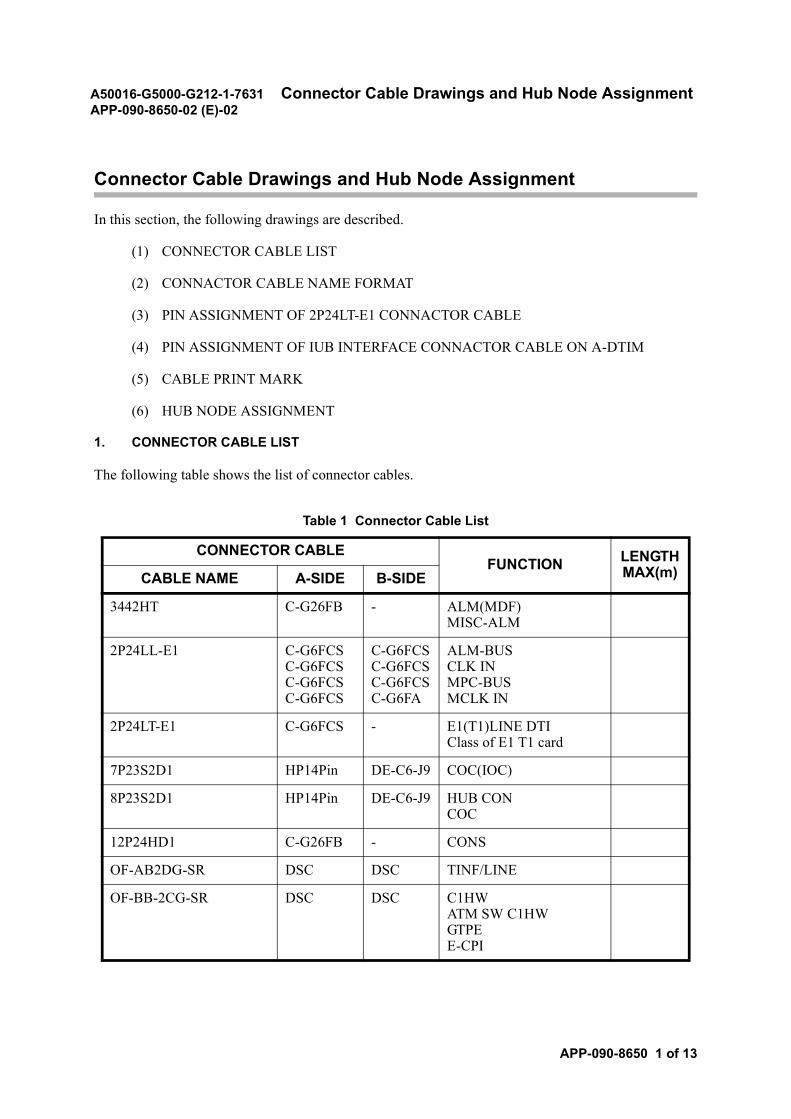
A50016-G5000-G212-1-7631 Connector Cable Drawings and Hub Node AssignmentAPP-090-8650-02 (E)-02
APP-090-8650 1 of 13
Connector Cable Drawings and Hub Node Assignment
In this section, the following drawings are described.
(1) CONNECTOR CABLE LIST
(2) CONNACTOR CABLE NAME FORMAT
(3) PIN ASSIGNMENT OF 2P24LT-E1 CONNACTOR CABLE
(4) PIN ASSIGNMENT OF IUB INTERFACE CONNACTOR CABLE ON A-DTIM
(5) CABLE PRINT MARK
(6) HUB NODE ASSIGNMENT
1. CONNECTOR CABLE LIST
The following table shows the list of connector cables.
Table 1 Connector Cable List
CONNECTOR CABLEFUNCTION LENGTH
MAX(m)CABLE NAME A-SIDE B-SIDE
3442HT C-G26FB - ALM(MDF)MISC-ALM
2P24LL-E1 C-G6FCSC-G6FCSC-G6FCSC-G6FCS
C-G6FCSC-G6FCSC-G6FCSC-G6FA
ALM-BUSCLK INMPC-BUSMCLK IN
2P24LT-E1 C-G6FCS - E1(T1)LINE DTIClass of E1 T1 card
7P23S2D1 HP14Pin DE-C6-J9 COC(IOC)
8P23S2D1 HP14Pin DE-C6-J9 HUB CONCOC
12P24HD1 C-G26FB - CONS
OF-AB2DG-SR DSC DSC TINF/LINE
OF-BB-2CG-SR DSC DSC C1HWATM SW C1HW GTPEE-CPI
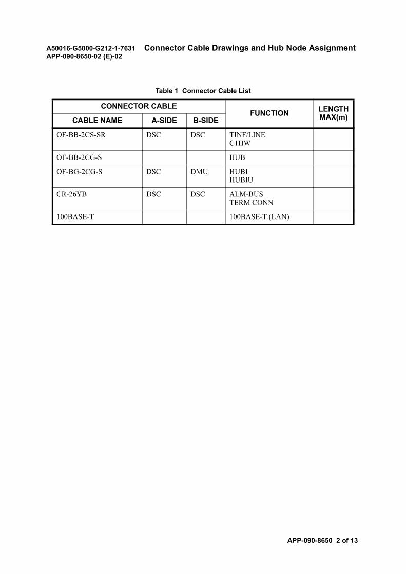
A50016-G5000-G212-1-7631 Connector Cable Drawings and Hub Node AssignmentAPP-090-8650-02 (E)-02
APP-090-8650 2 of 13
OF-BB-2CS-SR DSC DSC TINF/LINEC1HW
OF-BB-2CG-S HUB
OF-BG-2CG-S DSC DMU HUBIHUBIU
CR-26YB DSC DSC ALM-BUSTERM CONN
100BASE-T 100BASE-T (LAN)
Table 1 Connector Cable List
CONNECTOR CABLEFUNCTION LENGTH
MAX(m)CABLE NAME A-SIDE B-SIDE

A50016-G5000-G212-1-7631 Connector Cable Drawings and Hub Node AssignmentAPP-090-8650-02 (E)-02
APP-090-8650 3 of 13
2. CONNACTOR CABLE NAME FORMAT
This attachment regulates the item callout given to connector cables to be designed and ordered.Standardizing the callout of these items provides an efficient systematic organization of these cables.
Fig.1 and Fig.2 are the callout formats for general connector cables and fiber optic connector cables.
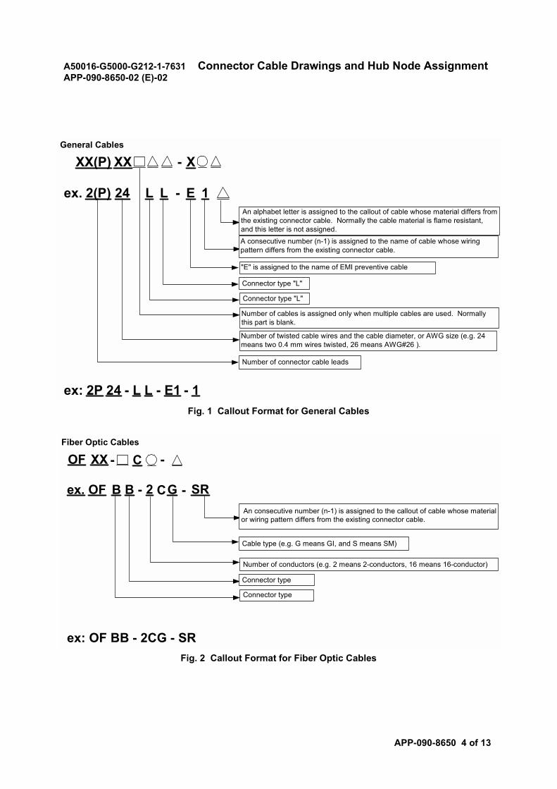
A50016-G5000-G212-1-7631 Connector Cable Drawings and Hub Node AssignmentAPP-090-8650-02 (E)-02
APP-090-8650 4 of 13
Fig. 1 Callout Format for General Cables
Fig. 2 Callout Format for Fiber Optic Cables
General Cables
XX(P) XX X-
ex. 2(P) 24 E-L L 1
Connector type "L"
Connector type "L"
Number of connector cable leads
An alphabet letter is assigned to the callout of cable whose material differs fromthe existing connector cable. Normally the cable material is flame resistant,and this letter is not assigned.A consecutive number (n-1) is assigned to the name of cable whose wiringpattern differs from the existing connector cable.
"E" is assigned to the name of EMI preventive cable
Number of cables is assigned only when multiple cables are used. Normallythis part is blank.
Number of twisted cable wires and the cable diameter, or AWG size (e.g. 24means two 0.4 mm wires twisted, 26 means AWG#26 ).
ex: 2P 24 - L L - E1 - 1
Fiber Optic Cables
OF XX -- C
ex. OF B B SR-2 C- G
Cable type (e.g. G means GI, and S means SM)
Number of conductors (e.g. 2 means 2-conductors, 16 means 16-conductor)
Connector type
Connector type
An consecutive number (n-1) is assigned to the callout of cable whose materialor wiring pattern differs from the existing connector cable.
ex: OF BB - 2CG - SR
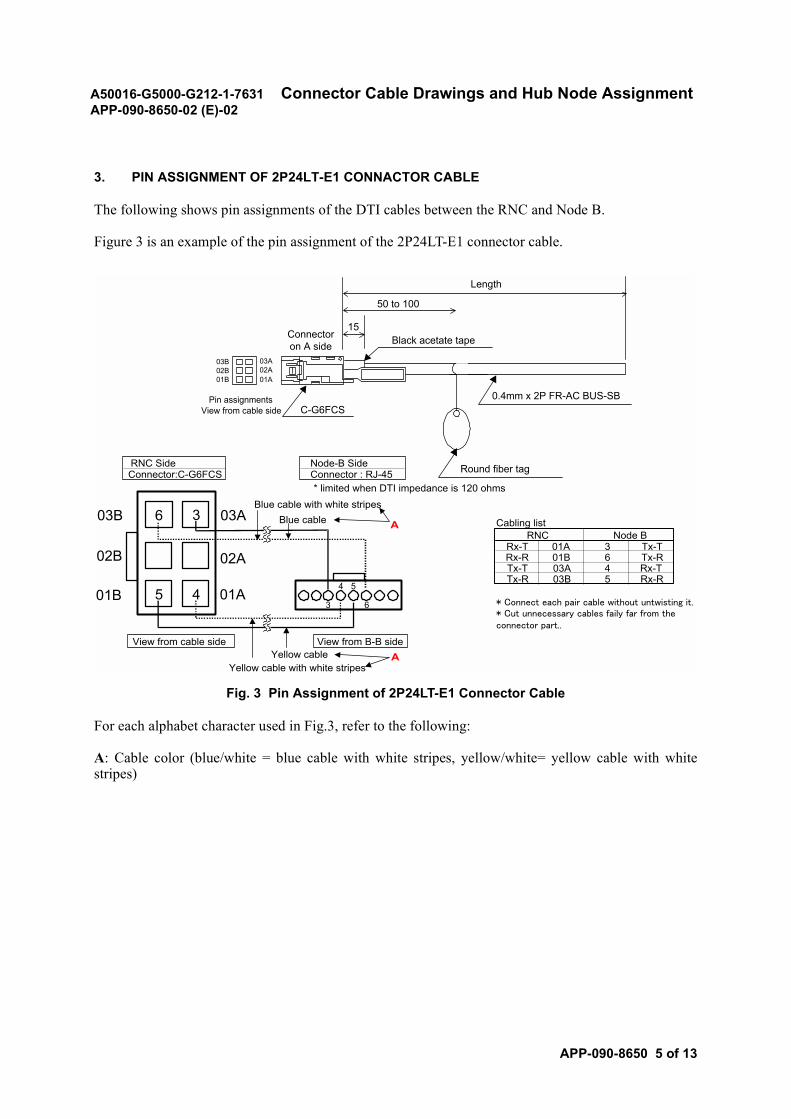
A50016-G5000-G212-1-7631 Connector Cable Drawings and Hub Node AssignmentAPP-090-8650-02 (E)-02
APP-090-8650 5 of 13
3. PIN ASSIGNMENT OF 2P24LT-E1 CONNACTOR CABLE
The following shows pin assignments of the DTI cables between the RNC and Node B.
Figure 3 is an example of the pin assignment of the 2P24LT-E1 connector cable.
Fig. 3 Pin Assignment of 2P24LT-E1 Connector Cable
For each alphabet character used in Fig.3, refer to the following:
A: Cable color (blue/white = blue cable with white stripes, yellow/white= yellow cable with whitestripes)
03B
01B02B
50 to 100
Connectoron A side
Pin assignmentsView from cable side C-G6FCS
Round fiber tag
Black acetate tape15
0.4mm x 2P FR-AC BUS-SB
03A02A01A
Length
RNC Side Node-B SideConnector:C-G6FCS Connector : RJ-45
* limited when DTI impedance is 120 ohms
Cabling list
Rx-T 01A 3 Tx-TRx-R 01B 6 Tx-RTx-T 03A 4 Rx-TTx-R 03B 5 Rx-R
* Connect each pair cable without untwisting it.* Cut unnecessary cables faily far from theconnector part..
View from cable side View from B-B side
Node BRNC
01A
02A
03A
5
3
4
6
01B
03B
02B
Blue cable with white stripesBlue cable
Yellow cable with white stripesYellow cable
A
A
3 6
54
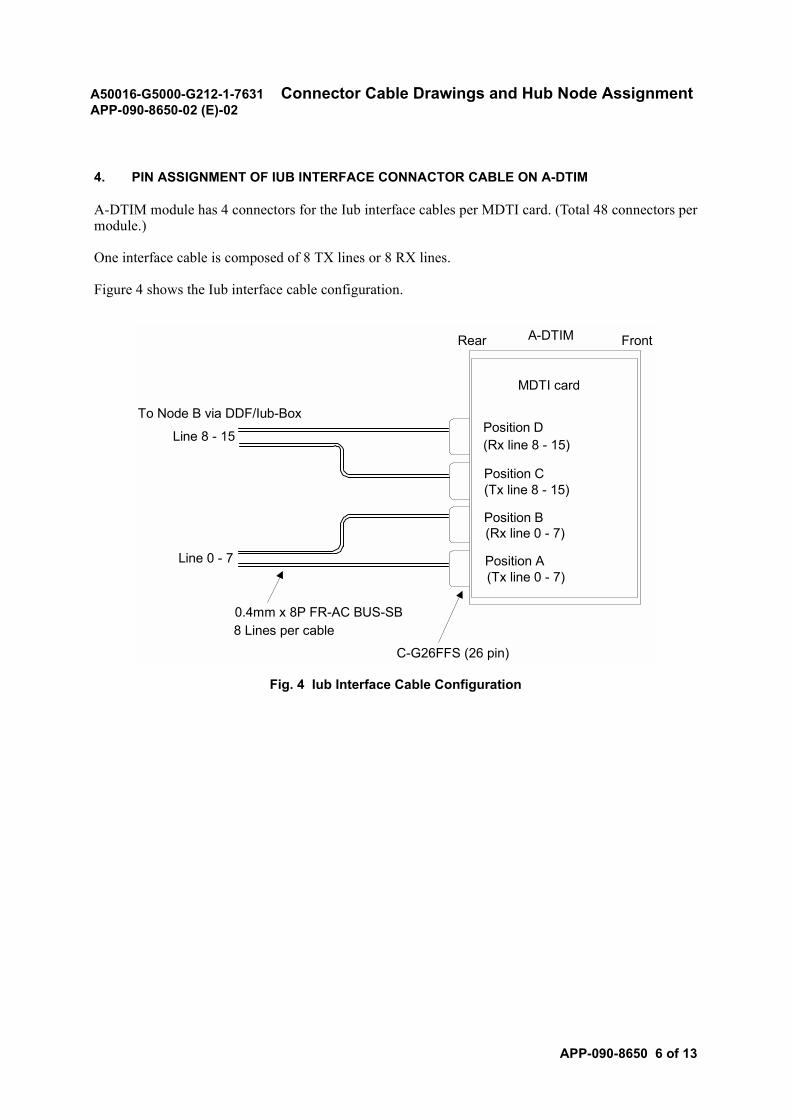
A50016-G5000-G212-1-7631 Connector Cable Drawings and Hub Node AssignmentAPP-090-8650-02 (E)-02
APP-090-8650 6 of 13
4. PIN ASSIGNMENT OF IUB INTERFACE CONNACTOR CABLE ON A-DTIM
A-DTIM module has 4 connectors for the Iub interface cables per MDTI card. (Total 48 connectors permodule.)
One interface cable is composed of 8 TX lines or 8 RX lines.
Figure 4 shows the Iub interface cable configuration.
Fig. 4 Iub Interface Cable Configuration
Position A(Tx line 0 - 7)
Position B(Rx line 0 - 7)
Position C(Tx line 8 - 15)
Position D(Rx line 8 - 15)
A-DTIM
Line 0 - 7
Line 8 - 15
8 Lines per cable
Rear Front
MDTI card
To Node B via DDF/Iub-Box
0.4mm x 8P FR-AC BUS-SB
C-G26FFS (26 pin)
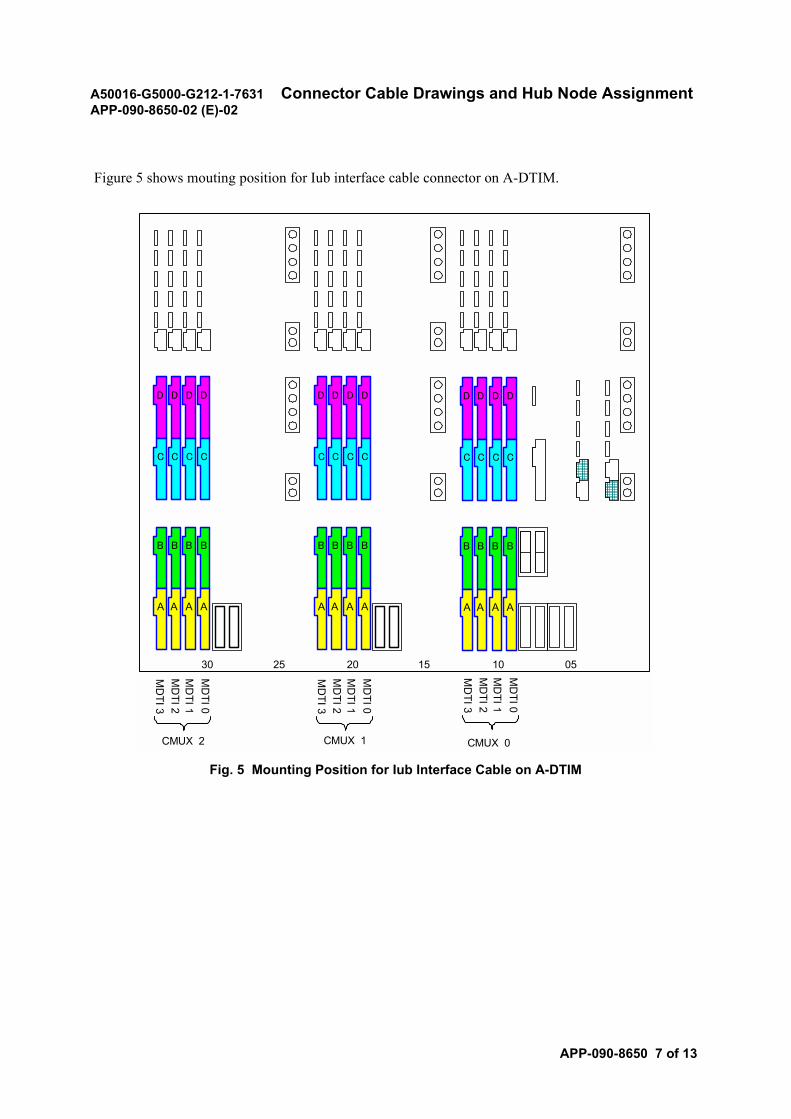
A50016-G5000-G212-1-7631 Connector Cable Drawings and Hub Node AssignmentAPP-090-8650-02 (E)-02
APP-090-8650 7 of 13
Figure 5 shows mouting position for Iub interface cable connector on A-DTIM.
Fig. 5 Mounting Position for Iub Interface Cable on A-DTIM
A
BBB
A
B
AA
C
DDD
C
D
CC
A
BBB
A
B
AA
C
DDD
C
D
CC
A
BBB
A
B
AA
C
DDD
C
D
CC
30 25 20 15 10 05
CMUX 2
MD
TI 0M
DTI 1
MD
TI 2M
DTI 3
CMUX 1 CMUX 0
MD
TI 0M
DTI 1
MD
TI 2M
DTI 3
MD
TI 0M
DTI 1
MD
TI 2M
DTI 3
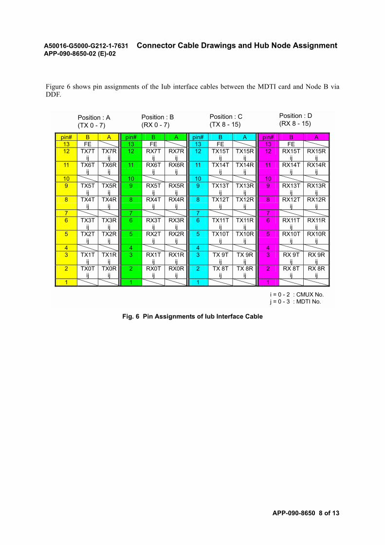
A50016-G5000-G212-1-7631 Connector Cable Drawings and Hub Node AssignmentAPP-090-8650-02 (E)-02
APP-090-8650 8 of 13
Figure 6 shows pin assignments of the Iub interface cables between the MDTI card and Node B viaDDF.
Fig. 6 Pin Assignments of Iub Interface Cable
i = 0 - 2 : CMUX No.j = 0 - 3 : MDTI No.
Position : A(TX 0 - 7)
Position : B(RX 0 - 7)
Position : C(TX 8 - 15)
Position : D(RX 8 - 15)
pin# B A pin# B A pin# B A pin# B A 13 FE 13 FE 13 FE 13 FE 12 TX7T
ij TX7R
ij 12 RX7T
ij RX7R
ij 12 TX15T
ij TX15R
ij 12 RX15T
ij RX15R
ij 11 TX6T
ij TX6R
ij 11 RX6T
ij RX6R
ij 11 TX14T
ij TX14R
ij 11 RX14T
ij RX14R
ij 10 10 10 10 9 TX5T
ij TX5R
ij 9 RX5T
ij RX5R
ij 9 TX13T
ij TX13R
ij 9 RX13T
ij RX13R
ij 8 TX4T
ij TX4R
ij 8 RX4T
ij RX4R
ij 8 TX12T
ij TX12R
ij 8 RX12T
ij RX12R
ij 7 7 7 7 6 TX3T
ij TX3R
ij 6 RX3T
ij RX3R
ij 6 TX11T
ij TX11R
ij 6 RX11T
ij RX11R
ij 5 TX2T
ij TX2R
ij 5 RX2T
ij RX2R
ij 5 TX10T
ij TX10R
ij 5 RX10T
ij RX10R
ij 4 4 4 4 3 TX1T
ij TX1R
ij 3 RX1T
ij RX1R
ij 3 TX 9T
ij TX 9R
ij 3 RX 9T
ij RX 9R
ij 2 TX0T
ij TX0R
ij 2 RX0T
ij RX0R
ij 2 TX 8T
ij TX 8R
ij 2 RX 8T
ij RX 8R
ij 1 1 1 1
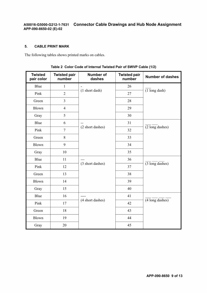
A50016-G5000-G212-1-7631 Connector Cable Drawings and Hub Node AssignmentAPP-090-8650-02 (E)-02
APP-090-8650 9 of 13
5. CABLE PRINT MARK
The following tables shows printed marks on cables.
Table 2 Color Code of Internal Twisted Pair of SWVP Cable (1/2)
Twisted pair color
Twisted pair number
Number of dashes
Twisted pair number Number of dashes
Blue 1 -(1 short dash)
26 ___(1 long dash)
Pink 2 27
Green 3 28
Blown 4 29
Gray 5 30
Blue 6 --(2 short dashes)
31 ___ ___(2 long dashes)
Pink 7 32
Green 8 33
Blown 9 34
Gray 10 35
Blue 11 ---(3 short dashes)
36 ___ ___ ___(3 long dashes)
Pink 12 37
Green 13 38
Blown 14 39
Gray 15 40
Blue 16 ----(4 short dashes)
41 ___ ___ ___ ___(4 long dashes)
Pink 17 42
Green 18 43
Blown 19 44
Gray 20 45
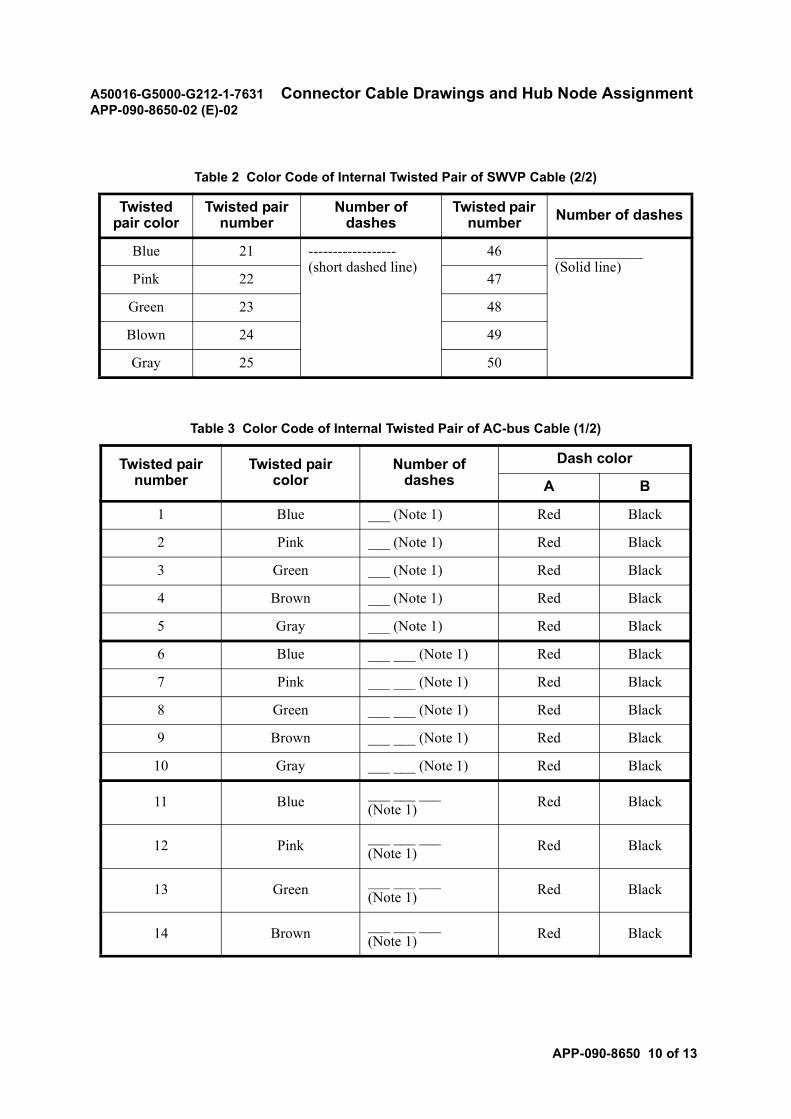
A50016-G5000-G212-1-7631 Connector Cable Drawings and Hub Node AssignmentAPP-090-8650-02 (E)-02
APP-090-8650 10 of 13
Blue 21 ------------------(short dashed line)
46 ____________(Solid line)
Pink 22 47
Green 23 48
Blown 24 49
Gray 25 50
Table 3 Color Code of Internal Twisted Pair of AC-bus Cable (1/2)
Twisted pair number
Twisted pair color
Number of dashes
Dash color
A B
1 Blue ___ (Note 1) Red Black
2 Pink ___ (Note 1) Red Black
3 Green ___ (Note 1) Red Black
4 Brown ___ (Note 1) Red Black
5 Gray ___ (Note 1) Red Black
6 Blue ___ ___ (Note 1) Red Black
7 Pink ___ ___ (Note 1) Red Black
8 Green ___ ___ (Note 1) Red Black
9 Brown ___ ___ (Note 1) Red Black
10 Gray ___ ___ (Note 1) Red Black
11 Blue ___ ___ ___(Note 1) Red Black
12 Pink ___ ___ ___(Note 1) Red Black
13 Green ___ ___ ___(Note 1) Red Black
14 Brown ___ ___ ___(Note 1) Red Black
Table 2 Color Code of Internal Twisted Pair of SWVP Cable (2/2)
Twisted pair color
Twisted pair number
Number of dashes
Twisted pair number Number of dashes
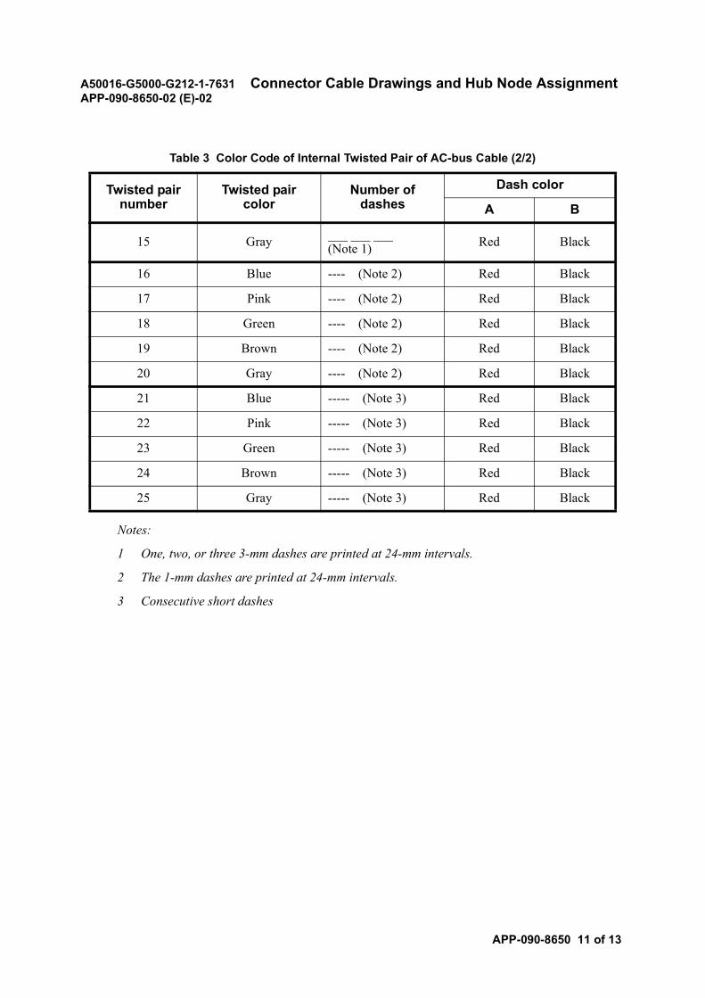
A50016-G5000-G212-1-7631 Connector Cable Drawings and Hub Node AssignmentAPP-090-8650-02 (E)-02
APP-090-8650 11 of 13
Notes:
1 One, two, or three 3-mm dashes are printed at 24-mm intervals.
2 The 1-mm dashes are printed at 24-mm intervals.
3 Consecutive short dashes
15 Gray ___ ___ ___(Note 1) Red Black
16 Blue ---- (Note 2) Red Black
17 Pink ---- (Note 2) Red Black
18 Green ---- (Note 2) Red Black
19 Brown ---- (Note 2) Red Black
20 Gray ---- (Note 2) Red Black
21 Blue ----- (Note 3) Red Black
22 Pink ----- (Note 3) Red Black
23 Green ----- (Note 3) Red Black
24 Brown ----- (Note 3) Red Black
25 Gray ----- (Note 3) Red Black
Table 3 Color Code of Internal Twisted Pair of AC-bus Cable (2/2)
Twisted pair number
Twisted pair color
Number of dashes
Dash color
A B
A50016-G5000-G212-1-7631 Connector Cable Drawings and Hub Node AssignmentAPP-090-8650-02 (E)-02
APP-090-8650 12 of 13
6. HUB NODE ASSIGNMENT
The switching equipment is connected to the controling equipment via hubs.
Call processors, which are connected to hubs using MPC bus cables, and other modules are controlledby software using switched virtual circuit (SVC) node numbers.
The option setting (C14D) assigns the node identification numbers. The hub cascade connection typesand the correlation between these modules and hub cascade connection determines the node ID rangepattern (14 patterns: pattern numbers. 0 to 6 are applied to the ASE, and pattern numbers. 21 to 23 areapplied to the CCPM.)
In RNC, the specification of frames determines the hub node ID assignment.
The current hub module basically accommodates 16 ports, but addition of hub modules enablesaccommodation of up to 40 ports.
Fig.7 is a hub node assignment example. For details of option setting patterns, refer to the optionsetting list, PART B.
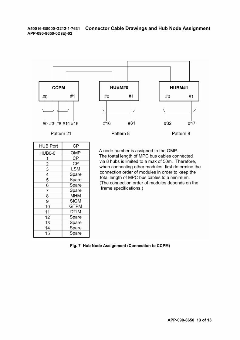
A50016-G5000-G212-1-7631 Connector Cable Drawings and Hub Node AssignmentAPP-090-8650-02 (E)-02
APP-090-8650 13 of 13
Fig. 7 Hub Node Assignment (Connection to CCPM)
HUB PortHUB0-0
123456789101112131415
Pattern 21 Pattern 8 Pattern 9
CCPM HUBM#0 HUBM#1
#0 #1#1 #1#0 #0
#0 #3 #8 #11 #15 #16 #31 #32 #47
OMPCPCP
LSMSpareSpareSpareSpareMHMSIGMGTPMDTIMSpareSpareSpareSpare
CPA node number is assigned to the OMP.The toatal length of MPC bus cables connectedvia 8 hubs is limited to a max of 50m. Therefore,when connecting other modules, first determine theconnection order of modules in order to keep thetotal length of MPC bus cables to a minimum.(The connection order of modules depends on theframe specifications.)

A50016-G5000-G212-1-7631ND-57268-706 (E)-01
SECTION 11CHECK BEFORE POWER-ON
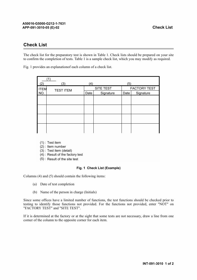
A50016-G5000-G212-1-7631APP-091-3010-05 (E)-02 Check List
INT-091-3010 1 of 2
Check List
The check list for the preparatory test is shown in Table 1. Check lists should be prepared on your siteto confirm the completion of tests. Table 1 is a sample check list, which you may modify as required.
Fig. 1 provides an explanationof each column of a check list.
Fig. 1 Check List (Example)
Columns (4) and (5) should contain the following items:
(a) Date of test completion
(b) Name of the person in charge (Initials)
Since some offices have a limited number of functions, the test functions should be checked prior totesting to identify those functions not provided. For the functions not provided, enter "NOT" on"FACTORY TEST" and "SITE TEST".
If it is determined at the factory or at the sight that some tests are not necessary, draw a line from onecorner of the column to the opposite corner for each item.
TEST ITEM
(2) (3) (4) (5)
(1) :(2) :(3) :(4) :
Test itemItem numberTest item (detail)Result of the factory test
(5) : Result of the site test
ITEMNO.
FACTORY TESTSITE TESTDate Signature
(1)
Date Signature
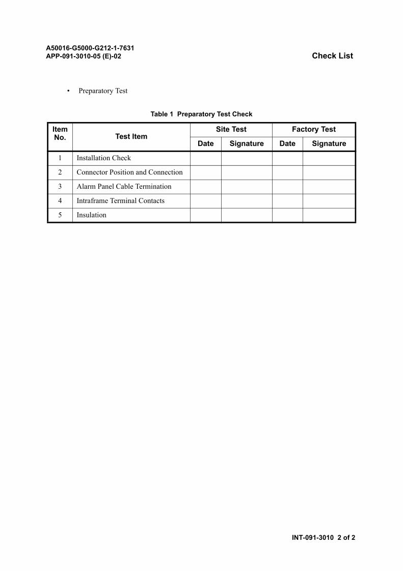
A50016-G5000-G212-1-7631APP-091-3010-05 (E)-02 Check List
INT-091-3010 2 of 2
• Preparatory Test
Table 1 Preparatory Test Check
Item No. Test Item
Site Test Factory Test
Date Signature Date Signature
1 Installation Check
2 Connector Position and Connection
3 Alarm Panel Cable Termination
4 Intraframe Terminal Contacts
5 Insulation
A50016-G5000-G212-1-7631APP-091-1010-05 (E)-01 Installation Check
PRC-091-1010 1 of 2
Installation Check
1. SUMMARY
This test verifies that Radio Network Controller (RNC) equipment is installed in accordance with theInstallation Drawing.
Check the following frames and equipment:
• Line Switch Frame (LSF)
• Trunk Frame (TRKF)
• Packet Radio Link Control Frame (PRF)
• Operation & Maintenance (O&M) Terminal
• Additional on-line or off-line peripheral equipment, provided by the customer, that connectsto the installed RNC.
2. CONDITIONS
None.
3. REFERENCE
Refer to the following in this manual.
• Work Flow and Installation Process Chart
• Installing Equipment Frame
• Module and Card Allocation Check
A50016-G5000-G212-1-7631APP-091-1010-05 (E)-01 Installation Check
PRC-091-1010 2 of 2
4. PROCEDURE
STEP PROCEDURE
1 Confirm that each frame has the correct part number and is installed in the correctlocation and position.Refer to Installing Equipment Frame in this manual.
2 Confirm that each frame contains the correct module type (part number) and quantityand that each module is installed in the correct location.Refer to Work Flow and Installation Process Chart in this manual.
3 Confirm that each module in each frame contains the correct card types and quantityand that each card is mounted in the correct location.Refer to Module and Card Allocation Check in this manual.
4 Confirm that the O&M terminal is installed in the correct location and position.Refer to Installing Equipment Frame in this manual.
5 Confirm that all the customer-provided equipment is installed in the correct location.
A50016-G5000-G212-1-7631APP-091-1020-05 (E)-01 Connector Position and Connection
PRC-091-1020 1 of 1
Connector Position and Connection
1. SUMMARY
This test confirms that Radio Network Controller (RNC) equipment connector positions are properlysecured.
Check all connector positions and connections in each frame.
2. CONDITIONS
None.
3. REFERENCE
Refer to Cable Preparation in this manual.
4. PROCEDURE
STEP PROCEDURE
1 Confirm that each cable is properly identified and tagged.For cable length, cable part number and connector termination positions, refer to CablePreparation in this manual.
2 Confirm that each connector termination position corresponds to the position shown inDTI Cable Laying in this manual.
3 Confirm that each cable connector properly connects to its corresponding RNCequipment connector termination position.Refer to DTI Cable Laying in this manual.
A50016-G5000-G212-1-7631APP-091-1030-05 (E)-01 Alarm Panel Cable Termination
PRC-091-1030 1 of 1
Alarm Panel Cable Termination
1. SUMMARY
This test confirms that the alarm panel cable terminations between Radio Network Controller (RNC)and alarm panels are accurately secured.
2. CONDITIONS
None.
3. REFERENCE
Refer to Alarm Panel Cable Connections from DF in this manual.
4. PROCEDURE
STEP PROCEDURE
1 Confirm that each alarm panel cable is properly identified and tagged.To determine the locations of all the alarm panel cables, refer to Alarm Panel CableConnections from DF in this manual.
2 Using an Integrated Circuit (IC) buzzer, multimeter or bell, verify that both ends ofeach alarm panel cable are correctly installed.

A50016-G5000-G212-1-7631APP-091-1040-05 (E)-01 Intraframe Terminal Contacts
PRC-091-1040 1 of 1
Intraframe Terminal Contacts
1. SUMMARY
This test confirms that the cabling and wiring terminal connections and modules within the RadioNetwork Controller (RNC) frames are properly secured and free of debris.
Check the following frames and equipment:
• Line Switch Frame (LSF)
• Trunk Frame (TRKF)
• Packet Radio Link Control Frame (PRF)
• Operation & Maintenance (O&M) Terminal
• Additional on-line or off-line peripheral equipment, provided by the customer, that connectsto the installed RNC equipment.
2. CONDITIONS
None.
3. REFERENCE
Refer to Interframe Cable Connection in this manual.
4. PROCEDURE
STEP PROCEDURE
1 Check for bent contacts and miscellaneous debris around the contact area.Refer to Interframe Cable Connection in this manual.
2 Check each unit, mounted in each frame, for bent terminals, unnecessary contact withother terminals and debris around the terminal area.
3 Carefully straighten each bent terminal and remove any debris from the terminal area.
A50016-G5000-G212-1-7631APP-091-1050-05 (E)-01 Insulation
PRC-091-1050 1 of 4
Insulation
1. SUMMARY
This test confirms that NO short circuits exist among -48V, Ground (G), Earth (E), and Frame Earth(FE) terminals to the Radio Network Controller (RNC) equipment prior to applying power.
Check the following frames and equipment:
• Line Switch Frame (LSF)
• Trunk Frame (TRKF)
• Packet Radio Link Control Frame (PRF)
• Operation & Maintenance (O&M) Terminal
• Additional on-line or off-line peripheral equipment, provided by the customer, that connectsto the installed RNC equipment.
2. CONDITIONS
This test requires an insulation resistance tester.
3. REFERENCE
Fig. 1 shows the Power and Ground Cable Connections.
Table 1 shows the Power and Ground Cable Connections.
Table 2 shows the Card List on the Fuse Panel.
Table 3 shows the Card List on the Power Distribution Module (PDM).
4. PROCEDURE
STEP PROCEDURE
1 Disconnect all leads from the Master Ground Bar (MGB).See Fig. 1 and Table 1.
2 Remove fuses from the Direct Current-Power Distribution Board (DC-PDB).
3 Remove all the fuses from the fuse panels on all the frames or turn off all the PowerDistribution Module (PDM) circuit breakers.
4 Remove all the cards from the fuse panels or PDM on all the frames.Refer to Tables 2 and 3.
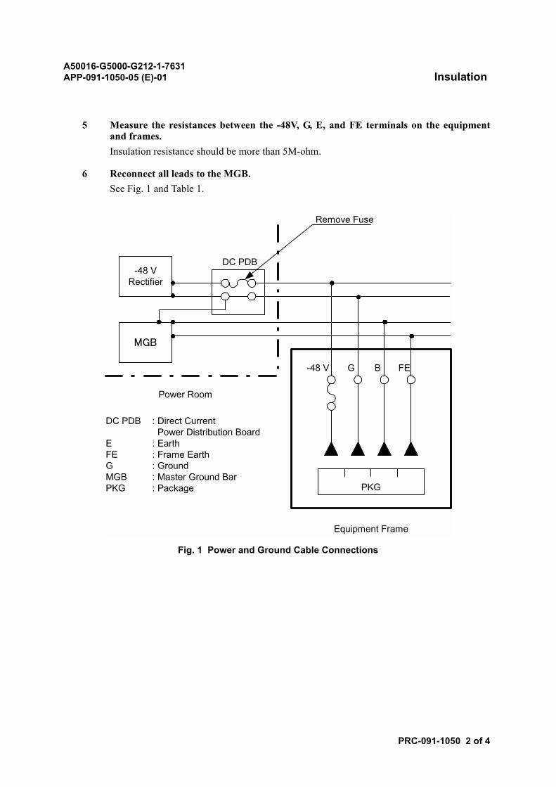
A50016-G5000-G212-1-7631APP-091-1050-05 (E)-01 Insulation
PRC-091-1050 2 of 4
5 Measure the resistances between the -48V, G, E, and FE terminals on the equipmentand frames.Insulation resistance should be more than 5M-ohm.
6 Reconnect all leads to the MGB.See Fig. 1 and Table 1.
Fig. 1 Power and Ground Cable Connections
DC PDB-48 V
Rectifier
MGB
-48 V G B FE
PKG
Equipment Frame
Power Room
Remove Fuse
DC PDB
EFEGMGBPKG
: Direct Current Power Distribution Board: Earth: Frame Earth: Ground: Master Ground Bar: Package
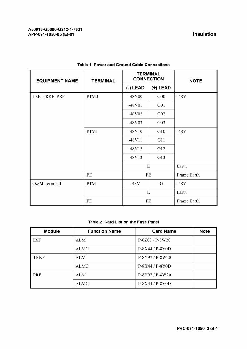
A50016-G5000-G212-1-7631APP-091-1050-05 (E)-01 Insulation
PRC-091-1050 3 of 4
Table 1 Power and Ground Cable Connections
EQUIPMENT NAME TERMINALTERMINAL
CONNECTION NOTE(-) LEAD (+) LEAD
LSF, TRKF, PRF PTM0 -48V00 G00 -48V
-48V01 G01
-48V02 G02
-48V03 G03
PTM1 -48V10 G10 -48V
-48V11 G11
-48V12 G12
-48V13 G13
E Earth
FE FE Frame Earth
O&M Terminal PTM -48V G -48V
E Earth
FE FE Frame Earth
Table 2 Card List on the Fuse Panel
Module Function Name Card Name Note
LSF ALM P-8Z83 / P-8W20
ALMC P-8X44 / P-8Y0D
TRKF ALM P-8Y97 / P-8W20
ALMC P-8X44 / P-8Y0D
PRF ALM P-8Y97 / P-8W20
ALMC P-8X44 / P-8Y0D
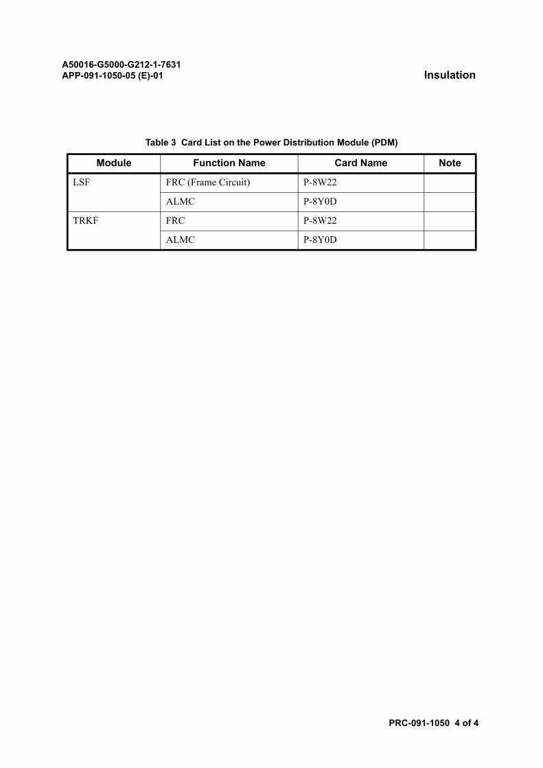
A50016-G5000-G212-1-7631APP-091-1050-05 (E)-01 Insulation
PRC-091-1050 4 of 4
Table 3 Card List on the Power Distribution Module (PDM)
Module Function Name Card Name Note
LSF FRC (Frame Circuit) P-8W22
ALMC P-8Y0D
TRKF FRC P-8W22
ALMC P-8Y0D


