Embed Size (px)
Citation preview
Advanced Connectivity Solutions100 S. Roosevelt Avenue, Chandler, AZ 85226Tel: 480-961-1382 Fax: 480-961-4533 www.rogerscorp.com
Page 1 of 4
RO4830(TM) High Frequency Laminates
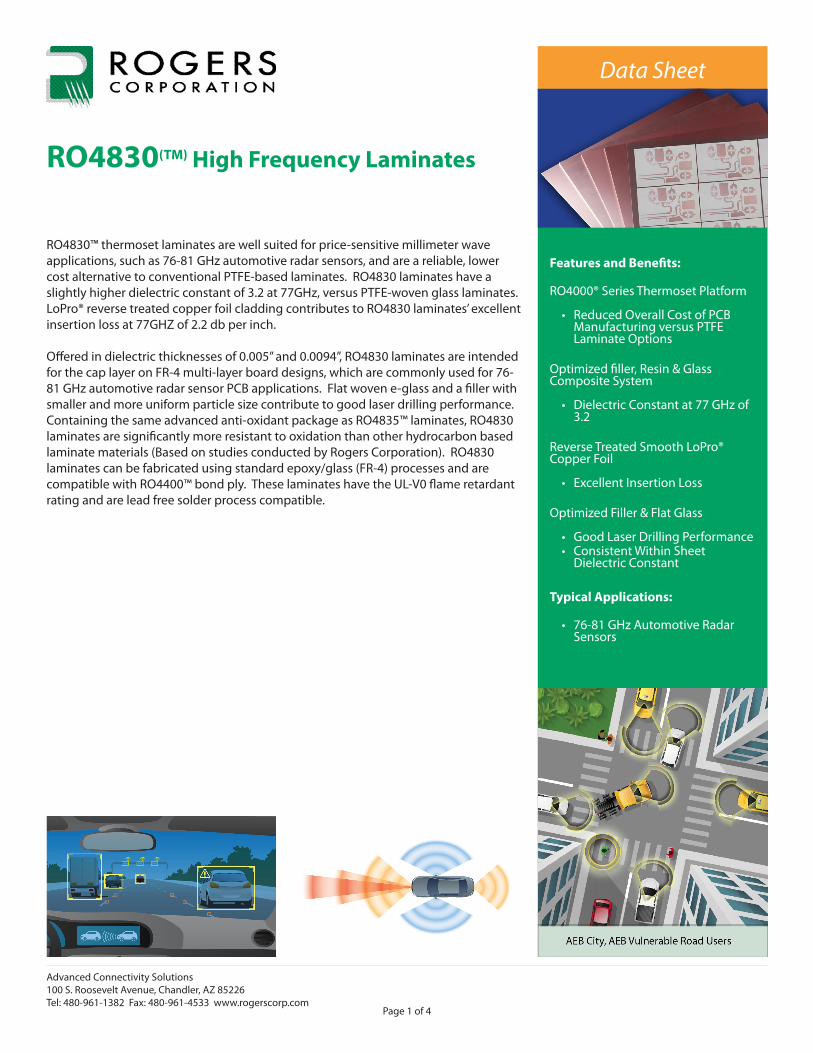
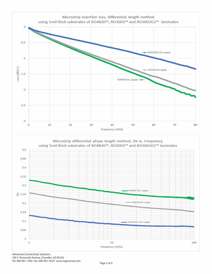
RO4830™ thermoset laminates are well suited for price-sensitive millimeter wave applications, such as 76-81 GHz automotive radar sensors, and are a reliable, lower cost alternative to conventional PTFE-based laminates. RO4830 laminates have a slightly higher dielectric constant of 3.2 at 77GHz, versus PTFE-woven glass laminates. LoPro® reverse treated copper foil cladding contributes to RO4830 laminates’ excellent insertion loss at 77GHZ of 2.2 db per inch.
Offered in dielectric thicknesses of 0.005” and 0.0094”, RO4830 laminates are intended for the cap layer on FR-4 multi-layer board designs, which are commonly used for 76-81 GHz automotive radar sensor PCB applications. Flat woven e-glass and a filler with smaller and more uniform particle size contribute to good laser drilling performance. Containing the same advanced anti-oxidant package as RO4835™ laminates, RO4830 laminates are significantly more resistant to oxidation than other hydrocarbon based laminate materials (Based on studies conducted by Rogers Corporation). RO4830 laminates can be fabricated using standard epoxy/glass (FR-4) processes and are compatible with RO4400™ bond ply. These laminates have the UL-V0 flame retardant rating and are lead free solder process compatible.
Features and Benefits:
RO4000® Series Thermoset Platform
• Reduced Overall Cost of PCB Manufacturing versus PTFE Laminate Options
Optimized filler, Resin & Glass Composite System
• Dielectric Constant at 77 GHz of 3.2
Reverse Treated Smooth LoPro® Copper Foil
• Excellent Insertion Loss
Optimized Filler & Flat Glass
• Good Laser Drilling Performance• Consistent Within Sheet
Dielectric Constant
Typical Applications:
• 76-81 GHz Automotive Radar Sensors
Data Sheet
Advanced Connectivity Solutions100 S. Roosevelt Avenue, Chandler, AZ 85226Tel: 480-961-1382 Fax: 480-961-4533 www.rogerscorp.com
Page 2 of 4
Advanced Connectivity Solutions100 S. Roosevelt Avenue, Chandler, AZ 85226Tel: 480-961-1382 Fax: 480-961-4533 www.rogerscorp.com
Page 3 of 4
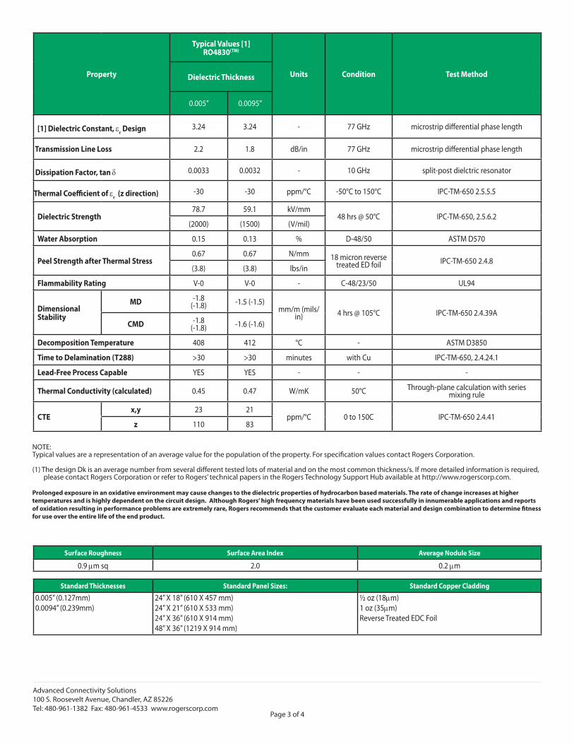
Standard Thicknesses Standard Panel Sizes: Standard Copper Cladding
0.005” (0.127mm)0.0094” (0.239mm)
24” X 18” (610 X 457 mm) 24” X 21” (610 X 533 mm)24” X 36” (610 X 914 mm)48” X 36” (1219 X 914 mm)
½ oz (18mm)1 oz (35mm)Reverse Treated EDC Foil
Property
Typical Values [1]RO4830(TM)
Units Condition Test MethodDielectric Thickness
0.005” 0.0095”
[1] Dielectric Constant, er Design 3.24 3.24 - 77 GHz microstrip differential phase length
Transmission Line Loss 2.2 1.8 dB/in 77 GHz microstrip differential phase length
Dissipation Factor, tan d 0.0033 0.0032 - 10 GHz split-post dielctric resonator
Thermal Coefficient of er (z direction) -30 -30 ppm/°C -50°C to 150°C IPC-TM-650 2.5.5.5
Dielectric Strength78.7 59.1 kV/mm
48 hrs @ 50°C IPC-TM-650, 2.5.6.2(2000) (1500) (V/mil)
Water Absorption 0.15 0.13 % D-48/50 ASTM D570
Peel Strength after Thermal Stress0.67 0.67 N/mm 18 micron reverse
treated ED foil IPC-TM-650 2.4.8(3.8) (3.8) lbs/in
Flammability Rating V-0 V-0 - C-48/23/50 UL94
Dimensional Stability
MD -1.8(-1.8) -1.5 (-1.5)
mm/m (mils/in) 4 hrs @ 105°C IPC-TM-650 2.4.39A
CMD -1.8 (-1.8) -1.6 (-1.6)
Decomposition Temperature 408 412 °C - ASTM D3850
Time to Delamination (T288) >30 >30 minutes with Cu IPC-TM-650, 2.4.24.1
Lead-Free Process Capable YES YES - - -
Thermal Conductivity (calculated) 0.45 0.47 W/mK 50°C Through-plane calculation with series mixing rule
CTEx,y 23 21
ppm/°C 0 to 150C IPC-TM-650 2.4.41z 110 83
NOTE:Typical values are a representation of an average value for the population of the property. For specification values contact Rogers Corporation.
(1) The design Dk is an average number from several different tested lots of material and on the most common thickness/s. If more detailed information is required, please contact Rogers Corporation or refer to Rogers’ technical papers in the Rogers Technology Support Hub available at http://www.rogerscorp.com.
Prolonged exposure in an oxidative environment may cause changes to the dielectric properties of hydrocarbon based materials. The rate of change increases at higher temperatures and is highly dependent on the circuit design. Although Rogers’ high frequency materials have been used successfully in innumerable applications and reports of oxidation resulting in performance problems are extremely rare, Rogers recommends that the customer evaluate each material and design combination to determine fitness for use over the entire life of the end product.
Surface Roughness Surface Area Index Average Nodule Size
0.9 mm sq 2.0 0.2 mm
The information in this data sheet is intended to assist you in designing with Rogers’ circuit materials. It is not intended to and does not create any warranties express or implied, including any warranty of merchantability or fitness for a particular purpose or that the results shown on this data sheet will be achieved by a user for a particular purpose. The user should determine the suitability of Rogers’ circuit materials for each application.
The Rogers’ logo, RO4830, RO4835, LoPro, RO3003, RO3003G2 and Helping power, protect, connect our world are trademarks of Rogers Corporation or one of its subsidiaries.© 2020 Rogers Corporation, Printed in U.S.A., All rights reserved. Revised 1470 061220 PUB# 92-182
Advanced Connectivity Solutions100 S. Roosevelt Avenue, Chandler, AZ 85226Tel: 480-961-1382 Fax: 480-961-4533 www.rogerscorp.com
Page 4 of 4