Embed Size (px)
Citation preview
OFFICIAL
OFFICIAL
ROAD BAY JETTY INSPECTION
GOVERNMENT OF THE BRITISH OVERSEAS TERRITORY OF ANGUILLA
65 Wks Gp RE 65/04_05_08 30 Jul 14
enabling operational effect through infrastructure
OFFICIAL
OFFICIAL
Chetwynd Barracks Chilwell Nottingham NG9 5HA Telephone:- Civil 0044 (0) 115 957 & Ext Mil 94451 & Ext Chief of Staff - Ext 2291 Technical Information Centre RE - Ext 2310 65 Works Group 2IC - Ext 2889 Email - [email protected]
170 (Infrastructure Support)
Engineer Group
170 Engineer Group consists of 6 Works Groups one of which is Army Reserve. Works Group capabilities include infrastructure consultancy, project management, engineering design, contract management and facilities management. We work on the overseas military estate, in post-conflict reconstruction and in support of Other Government Departments. Units are held at readiness and typically move early to theatre where they operate in all areas of the battlefield. Our people are our key asset and we rely completely on their agility, intellect and ability to work collaboratively. Our focus is on enabling commanders and other clients to deliver effect at best value.
enabling operational effect through infrastructure
OFFICIAL
i
OFFICIAL
TITLE PAGE
ROAD BAY JETTY INSPECTION
GOVERNMENT OF THE BRITISH OVERSEAS TERRITORY OF ANGUILLA
By 509 STRE (Port Infra)
65 Wks Gp RE
© Crown Copyright
65 Wks Gp RE 65/04_05_08 30 Jul 14
Authorised for Release Signed original Lt Col D Gray CO 65 Works Group RE 0115 957 2889 [email protected]
Prepared for Release Signed original Maj AP Nixon MBE OC 509 STRE (Port Infra) 0115 957 2889 [email protected]

OFFICIAL
ii
OFFICIAL
AMENDMENTS
Amendment Number Date of Insertion Initials
OFFICIAL
iii
OFFICIAL
DISTRIBUTION
This report will be held on the MOSS SharePoint page and distributed by electronic means. In order to ensure an efficient means of communicating information to those who need it the distribution table below shows the elements of the report required by individual posts.
Addressee
170 (Infra Sp) Engr Gp
Comd Asst Comd COS TICRE
65 Works Group RE CO 2IC OC 509 STRE (Port Infra)
British High Commission Defence Advisor Caribbean
Government of Anguilla
Her Excellency The Governor Ministry of Infrastructure, Communication, Utilities & Housing (MICUH)
OFFICIAL
iv
OFFICIAL
CONTENTS Page Title Page…. .................................................................................................................................. i Amendments ................................................................................................................................. ii Distribution .................................................................................................................................... iii Contents ....................................................................................................................................... iv Annexes ....................................................................................................................................... iv Figures ......................................................................................................................................... iv Tables ........................................................................................................................................ …v Drawings ....................................................................................................................................... v References .................................................................................................................................... v Executive Summary ...................................................................................... ……………………vii Report !INTRODUCTION ......................................................................................................................................... 1!
Requirement ...................................................................................................................................... 1!Aim ..................................................................................................................................................... 1!
BACKGROUND ........................................................................................................................................... 2!Geography of Anguilla ....................................................................................................................... 2!Road Bay Jetty .................................................................................................................................. 2!
STRUCTURAL SURVEY ............................................................................................................................. 3!General .............................................................................................................................................. 3!Overview of Existing Site and Structure ............................................................................................ 4!Use of Structure ................................................................................................................................. 5!Likely Causes of Damage .................................................................................................................. 5!Damaged to Structure ........................................................................................................................ 5 CostEstimates .................................................................................................................................... 5!
RECOMMENDATIONS FOR THE FUTURE ............................................................................................... 6!Residual Life of the Jetty ................................................................................................................... 6!Options for Future Anguilla Cargo Handling Facilities ....................................................................... 8!Summary of Costed Options ........................................................................................................... 12!
CONCLUSIONS ......................................................................................................................................... 12! Annexes A. Requirement Document ................................................................................................... A-1 B. Government of Anguilla Terms of Reference .................................................................. B-1 C. Anguilla Location Maps .................................................................................................... C-1 D. List of Key Personalities .................................................................................................. D-1 E. Inspection Report ............................................................................................................. E-1 Appendix 1 – List of Reference Documentation ............................................................ E1-1 Appendix 2 – Drawings .................................................................................................. E2-1 Appendix 3 – Summary of Visual Condition Survey & Inspection ................................. E3-1 Appendix 4 – Schedule of Repairs ................................................................................ E4-1 Appendix 5 – Suggested Repair Methods ..................................................................... E5-1 F. Photographs of Jetty ......................................................................................................... F-1 Figures Figure 1 Road Bay Jetty, Anguilla .......................................................................................... 3 Figure 2 New Purpose Built RO-RO Jetty .............................................................................. 4 Figure 3 RO-RO Ship Berthed 'Side-On' to the Jetty ............................................................. 7
OFFICIAL
v
OFFICIAL
Figure 4 Example of a Mass Structure Jetty .......................................................................... 9 Figure 5 Section through Proposed Extension ..................................................................... 10 Figure 6 Plan View of Proposed Extension & Extended RO-RO Capability ......................... 10 Figure C-1 Location of Anguilla in the Caribbean ............................................................... C – 1 Figure C-2 Map of Anguilla ................................................................................................. C – 1 Figure F1 Typical Damage to Pile ...................................................................................... F – 1 Figure F2 Typical Pile Cap Corrosion ................................................................................. F – 1 Figure F3 Jetty Approach Bent Soffit Delamination & Corrosion of Raking Piles ............... F – 2 Figure F4 Severe Damage to Failed Pile ........................................................................... F – 2 Figure F5 Underside to Bent showing Spalling & corrosion to Rebar ................................ F – 3 Figure F6 Underside to Jetty Approach showing Slab Delamination ................................. F – 3 Figure F7 Underside to Bent Showing Delamination and Rebar Corrosion ....................... F – 4 Figure F8 Main Jetty Spalling to Concrete around Raking Piles Showing Corrosion ......... F – 4 Figure F9 Underside Repair Extension to Pile Cap ............................................................ F – 5 Figure F10 Cracking to Main Jetty Approach Slab ............................................................... F – 5 Figure F11 Main Jetty Impact Damage ................................................................................ F – 6 Figure F12 Main Jetty Impact Damage to Edge Steel .......................................................... F – 6 Figure F13 Abrasion Damage to Main Jetty End .................................................................. F – 7 Figure F14 Main Jetty Surface Degradation ......................................................................... F – 7 Figure F15 Missing Ladder & Mooring Bollard Type 1 ......................................................... F – 8 Figure F16 Mooring Bollard Type 2 ...................................................................................... F – 8 Figure F17 Mooring Bollard Type 3 ...................................................................................... F – 9 Figure F18 Worn Surface of Jetty ......................................................................................... F – 9 Tables Table 1 Summary of Costed Repair Categories ................................................................... 6 Table 2 Summary of Costed Options .................................................................................. 11 Drawings 65/04_05_08/01 – General Arrangement Drawing 65/04_05_08/02 – Piling & Beam Layout Drawing 65/04_05_08/03 – Damage to Slabs & Beam Soffits 65/04_05_08/04 – Damage to Slabs & Surface of Jetty 65/04_05_08/05 – Jetty Mooring Bollards 65/04_05_08/06 – Sections Bent A to Bent K Jetty Approach 65/04_05_08/07 – Sections Bent L to Bent T Jetty Approach & Main Jetty 65/04_05_08/08 – Sections Bent T+1 to Bent T+8 Main Jetty 65/04_05_08/09 – Sections Bent T+8 to Bent Z Main Jetty 65/04_05_08/10 – Sections Bent Z+1 to Bent Y & Z North Face Main Jetty References A. Government of Anguilla, Anguilla Port Development and Management Study by Halcrow dated November 2002. B. Detailed Structural Survey of Jetty by dated 2002. C. Structural Survey of Jetty by Mouchel dated 1993.

OFFICIAL
vi
OFFICIAL
Intentionally blank
OFFICIAL
vii
OFFICIAL
EXECUTIVE SUMMARY
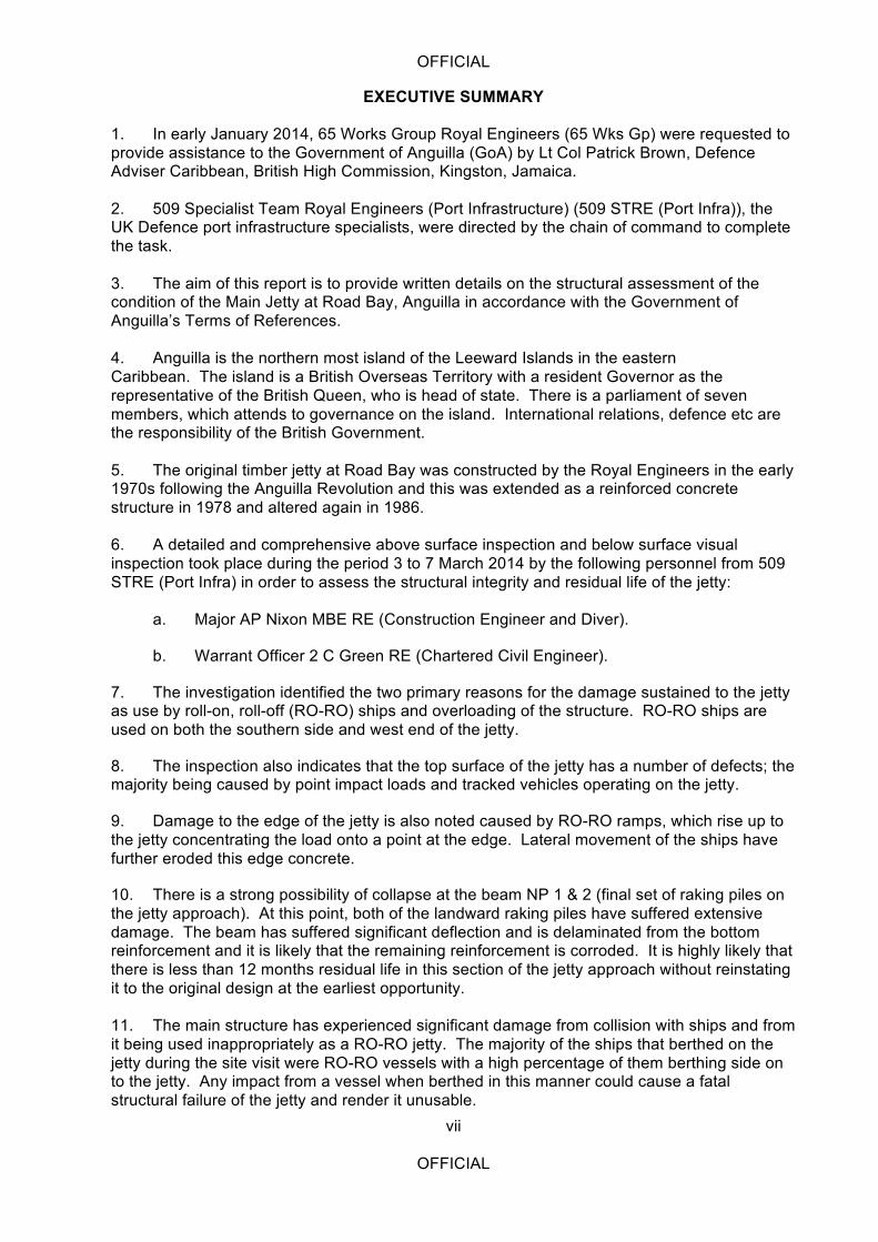
1. In early January 2014, 65 Works Group Royal Engineers (65 Wks Gp) were requested to provide assistance to the Government of Anguilla (GoA) by Lt Col Patrick Brown, Defence Adviser Caribbean, British High Commission, Kingston, Jamaica. 2. 509 Specialist Team Royal Engineers (Port Infrastructure) (509 STRE (Port Infra)), the UK Defence port infrastructure specialists, were directed by the chain of command to complete the task. 3. The aim of this report is to provide written details on the structural assessment of the condition of the Main Jetty at Road Bay, Anguilla in accordance with the Government of Anguilla’s Terms of References. 4. Anguilla is the northern most island of the Leeward Islands in the eastern Caribbean. The island is a British Overseas Territory with a resident Governor as the representative of the British Queen, who is head of state. There is a parliament of seven members, which attends to governance on the island. International relations, defence etc are the responsibility of the British Government. 5. The original timber jetty at Road Bay was constructed by the Royal Engineers in the early 1970s following the Anguilla Revolution and this was extended as a reinforced concrete structure in 1978 and altered again in 1986. 6. A detailed and comprehensive above surface inspection and below surface visual inspection took place during the period 3 to 7 March 2014 by the following personnel from 509 STRE (Port Infra) in order to assess the structural integrity and residual life of the jetty:
a. Major AP Nixon MBE RE (Construction Engineer and Diver).
b. Warrant Officer 2 C Green RE (Chartered Civil Engineer).
7. The investigation identified the two primary reasons for the damage sustained to the jetty as use by roll-on, roll-off (RO-RO) ships and overloading of the structure. RO-RO ships are used on both the southern side and west end of the jetty.
8. The inspection also indicates that the top surface of the jetty has a number of defects; the majority being caused by point impact loads and tracked vehicles operating on the jetty.
9. Damage to the edge of the jetty is also noted caused by RO-RO ramps, which rise up to the jetty concentrating the load onto a point at the edge. Lateral movement of the ships have further eroded this edge concrete.
10. There is a strong possibility of collapse at the beam NP 1 & 2 (final set of raking piles on the jetty approach). At this point, both of the landward raking piles have suffered extensive damage. The beam has suffered significant deflection and is delaminated from the bottom reinforcement and it is likely that the remaining reinforcement is corroded. It is highly likely that there is less than 12 months residual life in this section of the jetty approach without reinstating it to the original design at the earliest opportunity. 11. The main structure has experienced significant damage from collision with ships and from it being used inappropriately as a RO-RO jetty. The majority of the ships that berthed on the jetty during the site visit were RO-RO vessels with a high percentage of them berthing side on to the jetty. Any impact from a vessel when berthed in this manner could cause a fatal structural failure of the jetty and render it unusable.
OFFICIAL
viii
OFFICIAL
12. An estimate of remedial repairs has been undertaken based on the visual non-destructive inspection survey undertaken. The assessment indicates that breaking out of concrete and replacement of a percentage of corroded steel sections will be necessary. An assumption has been made that deterioration of the structure has not exceeded feasible repair methods requiring replacement of key elements. Breaking out of defective concrete to expose the extents of damage and corrosion to reinforcement steel will confirm this assumption. 13. The damaged elements are extensive and have therefore been split into four categories of repairs:
a. Immediate: Repairs that should be undertaken this year to prevent collapse of the structure.
b. Urgent: Repairs that should be undertaken as soon as possible as they are likely to deteriorate in the near future to an extent that immediate action is required.
c. Recommended: Repairs that should be undertaken as budget and programme allow to ensure the structure remains in good working order.
d. Monitored: Elements that should be inspected on an annual basis to ensure further deterioration does not occur.
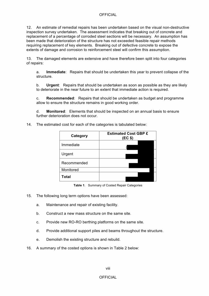
14. The estimated cost for each of the categories is tabulated below:
Category Estimated Cost GBP £ (EC $)
Immediate (
Urgent
Recommended
Monitored
Total
Table 1. Summary of Costed Repair Categories
15. The following long term options have been assessed:
a. Maintenance and repair of existing facility.
b. Construct a new mass structure on the same site.
c. Provide new RO-RO berthing platforms on the same site.
d. Provide additional support piles and beams throughout the structure.
e. Demolish the existing structure and rebuild.
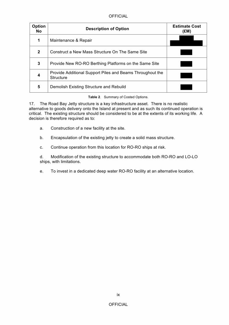
16. A summary of the costed options is shown in Table 2 below:
OFFICIAL
ix
OFFICIAL
Option No Description of Option Estimate Cost
(£M)
1 Maintenance & Repair
2 Construct a New Mass Structure On The Same Site
3 Provide New RO-RO Berthing Platforms on the Same Site
4 Provide Additional Support Piles and Beams Throughout the Structure
5 Demolish Existing Structure and Rebuild
Table 2. Summary of Costed Options.
17. The Road Bay Jetty structure is a key infrastructure asset. There is no realistic alternative to goods delivery onto the Island at present and as such its continued operation is critical. The existing structure should be considered to be at the extents of its working life. A decision is therefore required as to:
a. Construction of a new facility at the site.
b. Encapsulation of the existing jetty to create a solid mass structure.
c. Continue operation from this location for RO-RO ships at risk.
d. Modification of the existing structure to accommodate both RO-RO and LO-LO ships, with limitations.
e. To invest in a dedicated deep water RO-RO facility at an alternative location.

OFFICIAL
x
OFFICIAL
Intentionally blank
OFFICIAL
1
OFFICIAL
ROAD BAY JETTY INSPECTION
GOVERNMENT OF THE BRITISH OVERSEAS TERRITORY OF ANGUILLA
INTRODUCTION
1. In early January 2014, 65 Works Group Royal Engineers (65 Wks Gp) were requested to provide assistance to the Government of Anguilla (GoA) by Lt Col Patrick Brown, Defence Adviser Caribbean, British High Commission, Kingston, Jamaica. 2. 509 Specialist Team Royal Engineers (Port Infrastructure) (509 STRE (Port Infra), the UK Defence port infrastructure specialists, were directed by the chain of command to complete the task.
Requirement
3. The formal requirement document is at Annex A. 4. The requirement of the task is to:
a. Review the 1993 and 2002 structural reports of the Road Bay Jetty. b. Undertake a comprehensive survey of the jetty to assess its current structural integrity and residual life. c. Recommend the most appropriate repairs required to be carried out to the damaged and defected areas of the jetty identified in the survey and prioritise the order in which the work should be implemented in a detailed implementation plan. d. Make recommendations on the way forward for the existing jetty post repair regarding its structural integrity and residual life and what is the most suitable option for Anguilla’s cargo handling facilities including timeframe. e. In addition to (c) above, develop option layouts that will provide a suitable berthing facility for the next ten (10) years at the same location including a detailed implementation plan taking into account any environmental impacts. f. Produce estimate of the costs of the recommended remedial works in (c) and the alternative solutions in (d). g. Provide advice on suitable companies/contractors who could execute the work.
5. The GoA Terms of Reference (TOR) for the tasking is at Annex B.
Aim
6. The aim of this report is to provide written details on the structural assessment of the condition of the Main Jetty at Road Bay, Anguilla in accordance with GoA TORs. 7. The format of the inspection report will follow the same layout as the latest previous inspection report, Reference C, so that a direct comparison can be made on the condition of the jetty.
OFFICIAL
2
OFFICIAL
BACKGROUND
Geography of Anguilla
8. Anguilla is the northern most island of the Leeward Islands in the eastern Caribbean. A location map showing the position of Anguilla in the Caribbean is at Annex C. The island is a British Overseas Territory with a resident Governor as the representative of the British Queen, who is head of state. There is a parliament of seven members, which attends to governance on the island. International relations, defence etc are the responsibility of the British Government. 9. The island lies on the Anguilla Bank, close to its northern end. The bank extends for about 120 km north to south and up to about 70 km east to west. The water depth on the bank is generally less than 50 m. The other main islands on the Anguilla Bank are St Martin/St Maarten, which lies about 10 km to the south on the other side of the Anguilla Channel, and St Barthélémy (St Barts), which is a further 25 km to the south. There are numerous smaller islands, cays and reefs around Anguilla, most of which are uninhabited, but provide fishing grounds and/or tourist excursions. Water depths around the island are generally less than 25 m. The Island is long and thin being about 28 km long but only about 6 km wide at the widest place. The total land area is about 91 km2. The island is low-lying with an undulating rocky terrain. The highest point is Crocus Hill at an elevation of about 70 m. 10. There is little agriculture and most of the undeveloped land is covered by low scrub vegetation. There are numerous sandy beaches around the coast which provide a considerable tourist attraction. Elsewhere the coast is rocky, rising into low cliffs on parts of the north coast. Many of the beaches are on sand bars, which separate the sea from saline ponds, some of which were used as salinas for the production of solar salt in the past. This industry is now discontinued, but the ponds continue to provide a valuable habitat for wading birds and waterfowl. 11. Anguilla’s capital is at the centre of the island at The Valley. The island has an airport, Clayton J Lloyd Airport (fomally Wallblake Airport), with international connections to Antigua and Puerto Rico as well as other Caribbean Islands.
Road Bay Jetty
12. The original timber jetty at Road Bay was constructed by the Royal Engineers in the early 1970s following the Anguilla Revolution and this was extended as a reinforced concrete structure in 1978. 13. The timber jetty was demolished and replaced by a reinforced concrete approach in 1986 and an extension to the 1978 structure was constructed at the same time which forms the current Road Bay Main Cargo Jetty. The 1986 works were constructed by Samos Ltd. of Trinidad. designed the jetty and supervised its construction. Since its construction, minimal maintenance has been carried out on the structure. 14. In 1993 a detailed structural survey of the jetty was carried out by , which inter alia, revealed various degrees of physical damage, cracking and deterioration to three of the piles and 36 pile caps. The recommended remedial works were not carried out which resulted in further deterioration of the jetty.
OFFICIAL
3
OFFICIAL
15. From the time of the 1993 structural survey up to 2001 the cracks in the pile caps got worse and further serious damage occurred to a number of other piles from vessels and barges moored alongside. 16. In August 2001 the GoA Department of Infrastructure (DoI) carried out a preliminary inspection of the main structural members under the jetty head, which revealed a number of defects in the Deck Slab, Bent & Edge Beams, Pile Caps and Piles. 17. In 2002 another detailed structural survey of the jetty was undertaken by
, which inter alia, revealed various degrees of physical damage, cracking and deterioration of the jetty deck, jetty superstructure above piles and below surface and ancillary facilities. 18. The recommended remedial works in the 2002 structural survey report were carried out by – 2007. 19. In July 2013 the Ministry of Infrastructure, Communication, Utilities & Housing (MICUH) carried out another preliminary inspection of the main structural members under the jetty head, which revealed a number of defects in the Bent & Edge Beams, Pile Caps, Piles and under surface. It is also quite noticeable from visual observation that the jetty experiences significant lateral movement during the berthing of vessels.
STRUCTURAL SURVEY
General
20. A detailed and comprehensive above surface inspection and below surface visual inspection took place during the period 3 to 7 March 2014 by the following personnel from 509 STRE (Port Infra) in order to assess the structural integrity and residual life of the jetty:
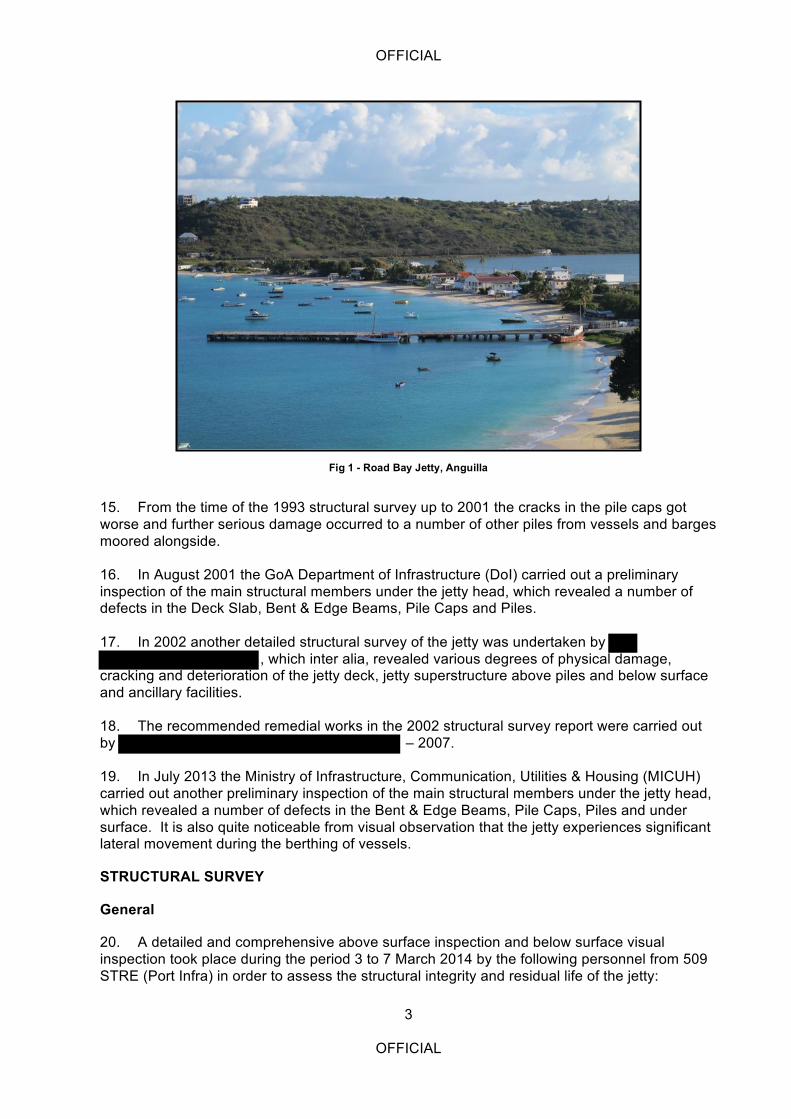
Fig 1 - Road Bay Jetty, Anguilla

OFFICIAL
4
OFFICIAL
a. Major AP Nixon MBE RE (Construction Engineer and Diver).
b. Warrant Officer 2 C Green RE (Chartered Civil Engineer).
21. A table showing the key personalities involved in the task is at Annex D. 22. The detailed findings of the structural assessment are included in the inspection report at Annex E.
Overview of Existing Site and Structure
23. The existing jetty is located in Road Bay on the west coast of the Island and as such benefits from protection from the majority of wind directions. Offshore protection is provided by a reef, which limits the size of waves hitting the structure. Drift direction is from South to North. The site is however limited by available draft levels of 4.0 m and dredging of the approaches to accommodate anything greater is not considered to be economically or environmentally viable. The jetty was built as a LO-LO structure consisting of three distinct elements as shown on Drawing No 65/04/_05_08/01:
a. The jetty approach structure constructed in 1985 to replace the original 1971 timber jetty.
b. The 1978 reinforced concrete extension to the jetty.
c. The 1985 reinforced concrete extension.
24. In addition to the above, a small, purpose built single RO-RO berth was built in 2008/2009 alongside the Main Jetty (see Fig 2). This berth falls outside the scope of this report.
Fig 2 - New Purpose Built RO-RO Jetty
OFFICIAL
5
OFFICIAL
Use of Structure
25. The jetty is used extensively by RO-RO and LO-LO ships of various size and displacements. Up to six vessels were noted mooring against the structure at any one time during the on-site observation of jetty operations with the largest vessel being up to 2,700 tonnes (MOSTEIN).
Likely Causes of Damage
26. The jetty was designed and constructed as a rigid LO-LO berthing facility and the use by RO-RO ships is undoubtedly the cause of much of the damage referred to in the inspection report. Overloading of the main structure was also reported with single loads of over 110 tonnes being offloaded. Many of the deliveries are bulk supplies including aggregates and building supplies. Concerns over speed limits and care in handling were raised in the inspection report. They have certainly resulted in damage to the jetty, particularly on the jetty approach where evidence of significant lateral loads in excess of the structures capacity have resulted in failure of a number of bents and supporting piles. The inspection report recommends operational changes and immediate repairs to the existing jetty which would need to be in place before any consideration of longer term options for use of the site could be considered.
Damaged to Structure
27. The inspection report identified the two primary reasons for the damage sustained to the jetty as use by RO-RO ships and overloading of the structure. RO-RO ships are used on both the southern side and west end of the jetty. This has resulted in loads being applied to the jetty that it was never designed to withstand. Any proposed medium to long-term option for use of this site would need to address these issues. Use of the jetty by several RO-RO’s at a time is operationally required to minimise the offloading time and although the new short jetty provides a single berth the operability of the jetty is not considered practical with use of just the west end of the main jetty and short jetty by the operating authority. Any proposed option would therefore require additional RO-RO compatible quay frontage. The inspection report also concludes that overloading of the structure is evident throughout. In particular the 1985 jetty approach is significantly damaged, caused by heavy loads being moved at speed and the vehicles rapidly decelerating. Short-term immediate repairs are indicated in the inspection report, however any long term option will require additional lateral resistance throughout the jetty approach. 28. The inspection report also indicates that the top surface of the jetty has a number of defects; the majority being caused by point impact loads and tracked vehicles operating on the jetty. Damage to the edge of the jetty is also noted caused by RO-RO ramps, which rise up to the jetty, concentrating the load onto a point at the edge. Lateral movement of the ships have further eroded this edge concrete. Edge protection considerations in any longer term option will therefore be required.
Cost Estimates
29. An estimate of remedial repairs has been undertaken based on the visual non-destructive inspection survey undertaken. The assessment indicates that breaking out of concrete and replacement of a percentage of corroded steel sections will be necessary. An assumption has been made that deterioration of the structure has not exceeded feasible repair methods requiring replacement of key elements. Breaking out of defective concrete to expose the extents of damage and corrosion to reinforcement steel will confirm this assumption.
OFFICIAL
6
OFFICIAL
30. The damaged elements are extensive and have therefore been split into four categories of repairs:
a. Immediate: Repairs that should be undertaken this year to prevent collapse of the structure.
b. Urgent: Repairs that should be undertaken as soon as possible as they are likely to deteriorate in the near future to an extent that immediate action is required.
c. Recommended: Repairs that should be undertaken as budget and programme allow to ensure the structure remains in good working order.
d. Monitored: Elements that should be inspected on an annual basis to ensure further deterioration does not occur.
31. The estimated cost for each of the categories is tabulated below:
Category Estimated Cost GBP £ (EC $)
Immediate
Urgent
Recommended
Monitored
Total
Table 1. Summary of Costed Repair Categories
RECOMMENDATIONS FOR THE FUTURE
Residual Life of the Jetty
32. It is difficult to predict the expected residual life in the jetty as elements of the structure have already failed to the point that significant repairs are required now to guarantee continuous operation. 33. If an alternative jetty was available to be used for the unloading of stores and cargo, the recommendation of this report would be that port operations are ceased until the priority repairs have been completed. 34. There is a strong possibility of collapse at the beam NP 1 & 2 (final set of raking piles on the jetty approach). At this point, both of the landward raking piles have suffered extensive damage. The beam has suffered significant deflection and is delaminated from the bottom reinforcement and it is likely that the remaining reinforcement is corroded. It is highly likely that there is less than 12 months residual life in this section of the jetty approach without reinstating it to the original designed capacity at the earliest opportunity. 35. The main structure has experienced significant damage from collision with ships and from it being used inappropriately as a RO-RO jetty. The majority of the ships that berthed on the jetty during the site visit were RO-RO vessels with a high percentage of them berthing side on to the jetty. Any impact from a vessel when berthed in this manner could cause a fatal structural failure of the jetty and render it unusable.
OFFICIAL
7
OFFICIAL
36. To continue to use the jetty at risk, the following operational restrictions need to be implemented:
a. A maximum speed limit of 5 mph needs to be imposed for all vehicles that operate on the jetty.
b. Berthing vessels onto the side of the jetty should cease immediately with greater utilisation of the end of the jetty as a RO-RO dock as well the use of the newer smaller purpose built RO-RO berth.
c. Only one vehicle should be allowed on the jetty approach at any one time.
d. Consideration should be given to imposing a maximum weight restriction on the jetty.
e. Supervision of dockside activities by the Port Authorities is vital to implement and maintain these restrictions.
f. All shipping agents should be made aware of the risks to their business if one of their ships damages the jetty further.
g. Until significant repairs have been carried out at the priority 1 location, further visual inspections should be undertaken after each period of heavy activity to monitor further deterioration and damage. If further deterioration is observed, a qualified structural engineer should be engaged to determine whether it is safe to continue to use the jetty.
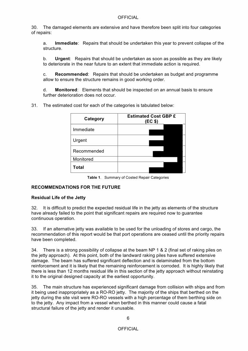
Fig 3 - RO-RO Ship Berthed 'Side-On' to the Jetty
OFFICIAL
8
OFFICIAL
Options for Future Anguilla Cargo Handling Facilities
37. Introduction. This report considers in the medium term extended use of the existing site as the main point of discharge of supplies to Anguilla. The options proposed and the preferred option selected are based upon:
a. The technical information available for the site.
b. Discussions with the Port Operating Authority, the Government of Anguilla and shipping operators.
c. Observations of Road Bay jetty operations.
d. Experience of similar port developments.
38. Requirement. The main requirement is the adaption of the existing jetty to support both Load On Load Off (LO-LO) and Roll On Roll Off (RO-RO) ships. 39. Options. The following options have been assessed:
a. Maintenance and repair of existing facility.
b. Construct a new mass structure on the same site.
c. Provide new RO-RO berthing platforms on the same site.
d. Provide additional support piles and beams throughout the structure.
e. Demolish the existing structure and rebuild.
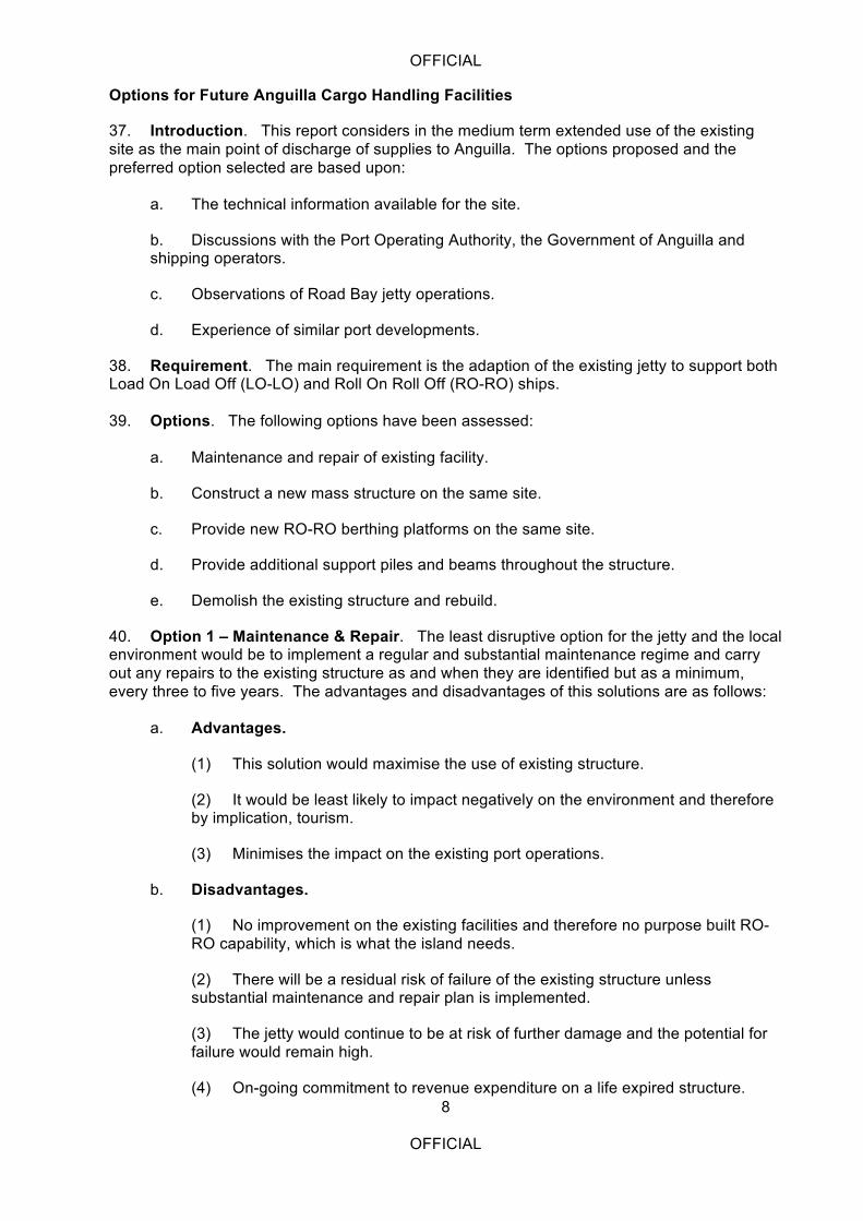
40. Option 1 – Maintenance & Repair. The least disruptive option for the jetty and the local environment would be to implement a regular and substantial maintenance regime and carry out any repairs to the existing structure as and when they are identified but as a minimum, every three to five years. The advantages and disadvantages of this solutions are as follows:
a. Advantages.
(1) This solution would maximise the use of existing structure.
(2) It would be least likely to impact negatively on the environment and therefore by implication, tourism.
(3) Minimises the impact on the existing port operations.
b. Disadvantages.
(1) No improvement on the existing facilities and therefore no purpose built RO-RO capability, which is what the island needs.
(2) There will be a residual risk of failure of the existing structure unless substantial maintenance and repair plan is implemented.
(3) The jetty would continue to be at risk of further damage and the potential for failure would remain high.
(4) On-going commitment to revenue expenditure on a life expired structure.
OFFICIAL
9
OFFICIAL
c. Estimated Cost. £650 k every three to five years.
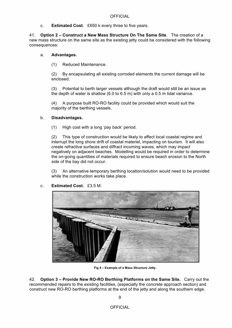
41. Option 2 – Construct a New Mass Structure On The Same Site. The creation of a new mass structure on the same site as the existing jetty could be considered with the following consequences:
a. Advantages.
(1) Reduced Maintenance.
(2) By encapsulating all existing corroded elements the current damage will be enclosed.
(3) Potential to berth larger vessels although the draft would still be an issue as the depth of water is shallow (6.0 to 6.5 m) with only a 0.5 m tidal variance.
(4) A purpose built RO-RO facility could be provided which would suit the majority of the berthing vessels.
b. Disadvantages.
(1) High cost with a long ‘pay back’ period.
(2) This type of construction would be likely to affect local coastal regime and interrupt the long shore drift of coastal materiel, impacting on tourism. It will also create refractive surfaces and diffract incoming waves, which may impact negatively on adjacent beaches. Modelling would be required in order to determine the on-going quantities of materials required to ensure beach erosion to the North side of the bay did not occur.
(3) An alternative temporary berthing location/solution would need to be provided while the construction works take place.
c. Estimated Cost. £3.5 M.
42. Option 3 – Provide New RO-RO Berthing Platforms on the Same Site. Carry out the recommended repairs to the existing facilities, (especially the concrete approach section) and construct new RO-RO berthing platforms at the end of the jetty and along the southern edge.
Fig 4 – Example of a Mass Structure Jetty.
OFFICIAL
10
OFFICIAL
a. Advantages.
(1) New independent structure that will take berthing loads and can be constructed so that it is RO-RO compatible.
(2) Minimises further collision damage on an already dilapidated structure.
(3) Work can be programmed to minimise disruption to current port operations.
(4) All works to be undertaken from the existing jetty structure to minimise costs.
(5) Little if any change to the impact on the environment.
(6) This will provide the opportunity to establish a leading edge more suitable to offloading RO-RO vessels.
b. Disadvantages.
(1) Still reliant on the existing structure for quay operations.
(2) Existing structure will still require ongoing maintenance, however, once the structure has been brought up to a satisfactory standard, further damage by impact from shipping will be minimised.
(3) The height of the existing jetty is higher than the optimum height required for RO-RO operations at this site.
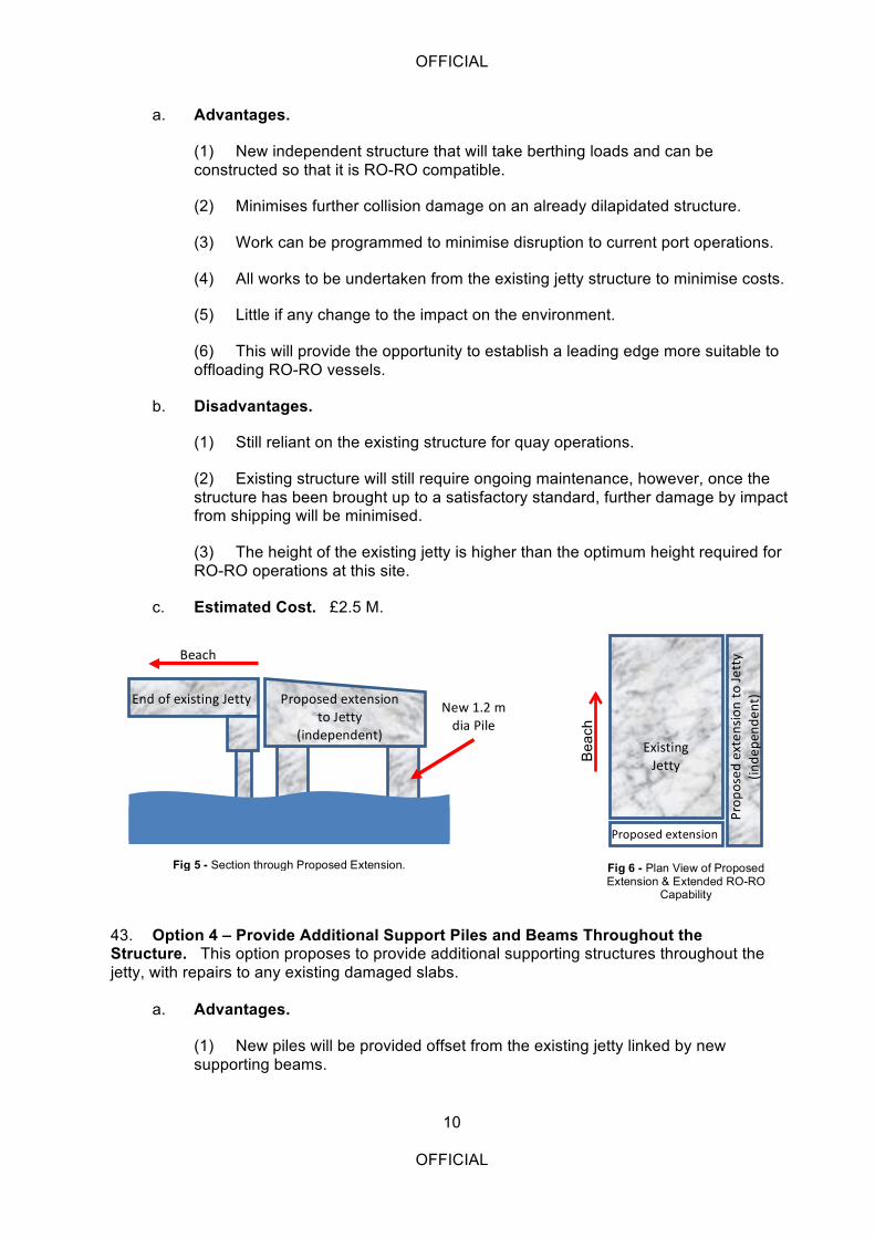
c. Estimated Cost. £2.5 M.
43. Option 4 – Provide Additional Support Piles and Beams Throughout the Structure. This option proposes to provide additional supporting structures throughout the jetty, with repairs to any existing damaged slabs.
a. Advantages.
(1) New piles will be provided offset from the existing jetty linked by new supporting beams.
Bea
ch
Existing(Jetty
Proposed(extension(
Prop
osed
(exten
sion
(to(Jetty(
(inde
pend
ent)
Fig 6 - Plan View of Proposed Extension & Extended RO-RO
Capability
End(of(existing(Jetty Proposed(extension(to(Jetty(
(independent)
Fig 5 - Section through Proposed Extension.
Beach
New(1.2(m(dia(Pile
OFFICIAL
11
OFFICIAL
(2) The additional supporting structure would be designed to withstand lateral loading forces from RO-RO vessels whilst providing additional horizontal support to the jetty slabs.
b. Disadvantages.
(1) Still reliant on the existing structure for quay operations.
(2) Existing structure will still require ongoing maintenance, however, once the structure has been brought up to a satisfactory standard, further damage by impact from shipping will be minimised.
(3) Care will need to be taken on the North side of the jetty to ensure the new piles do not obstruct the new RO-RO berth.
c. Estimated Cost. £2.5 M.
44. Option 5 – Demolish Existing Structure and Rebuild. Completely demolish the existing structure and construct a new, purposely designed structure.
a. Advantages.
(1) The existing site has a number of existing provisions that make it suitable for retaining a jetty at Road Bay. These include the good road network to the site and the storage, customs and holding facilities at the site.
(2) The existing site at Road Bay is well protected from storms and winds.
(3) A new, purpose built facility could be constructed capable of berthing LO-LO and RO-RO vessels.
b. Disadvantages.
(1) High cost.
(2) Unavailability of the facility during the reconstruction period.
(3) No change to the size of ship that can berth as the jetty will still be limited by draft within the bay.
(4) Tourism aspirations for the Bay would still be compromised by the continued use of the site as a port.
c. Estimated Cost. £5.0 M.
OFFICIAL
12
OFFICIAL
Summary of Costed Options
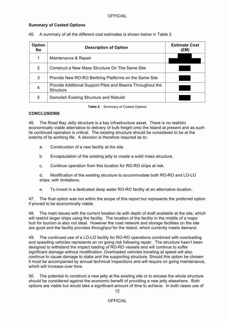
45. A summary of all the different cost estimates is shown below in Table 2.
Option No Description of Option Estimate Cost
(£M)
1 Maintenance & Repair
2 Construct a New Mass Structure On The Same Site
3 Provide New RO-RO Berthing Platforms on the Same Site
4 Provide Additional Support Piles and Beams Throughout the Structure
5 Demolish Existing Structure and Rebuild
Table 2. Summary of Costed Options
CONCLUSIONS
46. The Road Bay Jetty structure is a key infrastructure asset. There is no realistic economically viable alternative to delivery of bulk freight onto the Island at present and as such its continued operation is critical. The existing structure should be considered to be at the extents of its working life. A decision is therefore required as to:
a. Construction of a new facility at the site.
b. Encapsulation of the existing jetty to create a solid mass structure.
c. Continue operation from this location for RO-RO ships at risk.
d. Modification of the existing structure to accommodate both RO-RO and LO-LO ships, with limitations.
e. To invest in a dedicated deep water RO-RO facility at an alternative location.
47. The final option was not within the scope of this report but represents the preferred option if proved to be economically viable. 48. The main issues with the current location lie with depth of draft available at the site, which will restrict larger ships using the facility. The location of the facility in the middle of a major hub for tourism is also not ideal. However the road network and storage facilities on the site are good and the facility provides throughput for the Island, which currently meets demand. 49. The continued use of a LO-LO facility for RO-RO operations combined with overloading and speeding vehicles represents an on going risk following repair. The structure hasn’t been designed to withstand the impact loading of RO-RO vessels and will continue to suffer significant damage without modification. Overloaded vehicles traveling at speed will also continue to cause damage to slabs and the supporting structure. Should this option be chosen it must be accompanied by annual technical inspections and will require on going maintenance, which will increase over time. 50. The potential to construct a new jetty at the existing site or to encase the whole structure should be considered against the economic benefit of providing a new jetty elsewhere. Both options are viable but would take a significant amount of time to achieve. In both cases use of
OFFICIAL
13
OFFICIAL
the existing jetty during construction would not be possible. Encasing the existing jetty would provide a structure capable of withstanding the applied loads of ships using the jetty. However this option may cause disruption to the natural sediment movement within the bay, potentially leading to loss of beach material to the northern side of the bay, which supports the tourist industry. 51. Options to modify the structure to enhance its suitability to accommodate both RO-RO and LO-LO ships either by additional piling and cross beams to support the existing structure or by constructing an independent loading structure to the South and West sides of the jetty will increase its robustness and in the latter case improve RO-RO berthing. 52. For this reason and the relative cost of the two options the independent supported structure to the South and West side is the preferred option for medium term operability for Road Bay Jetty. At a cost of it represents a large investment in the jetty but is significantly cheaper than a new jetty at this location or at an alternative site. Of the two options the independent structure is preferred over strengthening of the existing structure as it provides improved docking for RO-RO ships. It should be noted that maintenance and repair to the existing structure will still need to be carried out should this option be selected as the preferred method of providing Road Bay with a berthing facility. Annexes A. Requirement Document. B. Government of Anguilla Terms of Reference. C. Anguilla Location Maps. D. List of Key Personalities. E. Inspection Report. Appendix 1 – List of Reference Documentation. Appendix 2 – Drawings. Appendix 3 – Summary of Visual Condition Survey & Inspection. Appendix 4 – Schedule of Repairs. Appendix 5 – Suggested Repair Methods. F. Photographs of Jetty.

OFFICIAL
14
OFFICIAL
Intentionally blank
OFFICIAL
A - 1
OFFICIAL
ANNEX A TO 65/04_05_08 DATED 30 JUL 14
REQUIREMENT DOCUMENT
IPP OVERSEAS SECURITY CO-OPERATION STTT REQUIREMENT
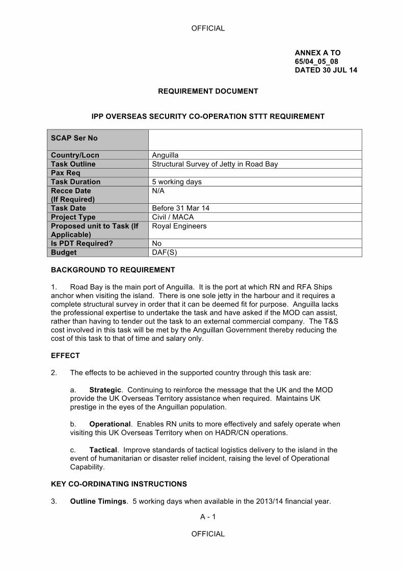
SCAP Ser No
Country/Locn Anguilla Task Outline Structural Survey of Jetty in Road Bay Pax Req Task Duration 5 working days Recce Date (If Required)
N/A
Task Date Before 31 Mar 14 Project Type Civil / MACA Proposed unit to Task (If Applicable)
Royal Engineers
Is PDT Required? No Budget DAF(S) BACKGROUND TO REQUIREMENT 1. Road Bay is the main port of Anguilla. It is the port at which RN and RFA Ships anchor when visiting the island. There is one sole jetty in the harbour and it requires a complete structural survey in order that it can be deemed fit for purpose. Anguilla lacks the professional expertise to undertake the task and have asked if the MOD can assist, rather than having to tender out the task to an external commercial company. The T&S cost involved in this task will be met by the Anguillan Government thereby reducing the cost of this task to that of time and salary only. EFFECT 2. The effects to be achieved in the supported country through this task are:
a. Strategic. Continuing to reinforce the message that the UK and the MOD provide the UK Overseas Territory assistance when required. Maintains UK prestige in the eyes of the Anguillan population.
b. Operational. Enables RN units to more effectively and safely operate when visiting this UK Overseas Territory when on HADR/CN operations.
c. Tactical. Improve standards of tactical logistics delivery to the island in the event of humanitarian or disaster relief incident, raising the level of Operational Capability.
KEY CO-ORDINATING INSTRUCTIONS 3. Outline Timings. 5 working days when available in the 2013/14 financial year.
OFFICIAL
A - 2
OFFICIAL
4. Team Requirements. 2 structural engineers, competent and capable of offering advice and assistance to a Ministerial level audience. 5. Course Content. N/A
6. Job Specifications (If Required). N/A 7. Contact Details for Initiator In-Country. Lt Col Patrick Brown, Defence Adviser Caribbean, British High Commission, Kingston +1876 371 0464 (GMT -5hrs). 8. Contact Details for IPP Desk Officer. Dr Andrew Falconer IPP-LAC2 +44 (0)20 7218 2060 [email protected]
OFFICIAL
B - 1
OFFICIAL
ANNEX B TO 65/04_05_08 DATED 30 JUL 14
TERMS OF REFERENCE
Government of Anguilla /
Anguilla Air & Sea Ports Authority
CONSULTANCY SERVICES FOR THE STRUCTURAL INSPECTION OF ROAD BAY MAIN
JETTY
OFFICIAL
B - 2
OFFICIAL
OCTOBER 2013
TERMS OF REFERENCE FOR
STRUCTURAL SURVEY OF ROAD BAY MAIN JETTY 1. Background Information 1.1 The present Road Bay Main Cargo Jetty was constructed in 1986 by Samos Ltd. of
Trinidad. LG Mouchel & Partners of UK designed the jetty and supervised its construction. Since its construction, minimal maintenance has been carried out on the structure.
1.2 In 1993 a detailed structural survey of the jetty was carried out by Mouchel, which inter
alia, revealed various degrees of physical damage, cracking and deterioration to 3 of the piles and 36 pilecaps. The recommended remedial works were not carried out which resulted in further deterioration of the jetty.
1.3 From the time of the structural survey up to 2001 the cracks in the pilecaps got worse
and further serious damage occurred to a number of other piles from vessels and barges moored alongside.
1.4 In August 2001 the Government of Anguilla’s (GoA) Department of Infrastructure (DoI)
carried out a preliminary inspection of the main structural members under the jetty head, which revealed a number of defects in the Deck Slab, Bent & Edge Beams, Pile Caps and Piles.
1.5 In 2002 another detailed structural survey of the jetty was undertaken by
, which inter alia, revealed various degrees of physical damage, cracking and deterioration of the jetty deck, jetty superstructure above piles and below surface and ancillary facilities.
1.6 The recommended remedial works in the 2002 structural survey report were carried out
by in 2006 – 2007. 1.7 In July 2013 the Ministry of Infrastructure, Communication, Utilities & Housing (MICUH)
carried out another preliminary inspection of the main structural members under the jetty head, which revealed a number of defects in the Bent & Edge Beams, Pile Caps, Piles and undersurface. It is also quite noticeable from visual observation that the jetty experience significant lateral movement during berthing of vessels.
1.8 While the jetty may not be in imminent danger of collapse and remains useable under
the current volume and weight of cargo transported over it, it is expedient that the damages and defects are repaired/replaced as soon as possible.
1.9 In order for any remedial work to be carried out GoA/AASPA requires a Consultant to
undertake a detailed structural inspection of the jetty.
OFFICIAL
B - 3
OFFICIAL
2. Requirements of the Consultancy 2.1 The Consultant is to:
(i) Review the 1993 and 2002 structural reports of the Road Bay Jetty. (ii) Undertake a comprehensive survey of the jetty to assess its current structural integrity and residual life. (iii) Recommend the most appropriate repairs required to be carried out to the damaged and defected areas of the jetty identified in the survey and prioritise the order in which the work should be implemented in a detailed implementation plan. (iv) Make recommendations on the way forward for the existing jetty post repair regarding its structural integrity and residual life and what is the most suitable option for Anguilla’s cargo handling facilities including timeframe. (v) In addition to (iii) above, develop option layouts that will provide a suitable berthing facility for the next ten (10) years at the same location including a detailed implementation plan taking into account any environmental impacts. (vi) Produce an estimate of the costs of the recommended remedial works in (iii) and the alternative solutions in (iv). (vii) Provide advice on suitable companies/contractors who could execute the work.
3. Duration of the Consultancy 3.1 It is envisaged that the Consultant will require not more than five (5) days in Anguilla to
carry out this assignment, followed by a short period at their home base to prepare the report.
4. Reporting 4.1 Within four (4) weeks of the completion of the survey work in Anguilla the Consultant will
be required to submit to the Permanent Secretary in the MICUH/CEO (Ag) AASPA three (3) copies of his report detailing the assignment’s findings and recommendations. The report should also be submitted in electronic copy.
5. Support Facilities to be Provided Locally 5.1 The first point of contact for formal communication between the Consultant and
MICUH/AASPA will be the Permanent Secretary MICUH/CEO (Ag) AASPA. 5.2 MICUH/AASPA will provide all documents, data, reports, statistics, information and maps
at the disposal of the GoA/AASPA that the Consultant may require for the purposes of the assignment.
5.3 As much notice as possible should be given by the Consultant to the Chief Engineer/CEO
(Ag) AASPA when making arrangements to use the above services and facilities.
OFFICIAL
B - 4
OFFICIAL
Personnel, Equipment, Facilities, and Services of Others to be Provided by the GoA/AASPA The Department of Infrastructure (DoI) of the Ministry of Infrastructure, Communication, Utilities and Housing (MICUH) and the Anguilla Air & Sea Ports Authority (AASPA) will provide the following services, facilities, documents and information, which the Consultant may require for the purpose of the assignment. (a) Dinghy, plus operator, for inspection work on jetty (b) Scuba air tanks for use by Consultant’s diver (c) All documents, data, reports, statistics, information and maps at the disposal of the
GoA/AASPA As much notice as possible should be given by the consultant to the Chief Engineer DoI/ CEO (Ag) AASPA when making arrangements to use the above services and facilities. October 2013
OFFICIAL
C - 1
OFFICIAL
ANNEX C TO 65/04_05_08 DATED 30 JUL 14
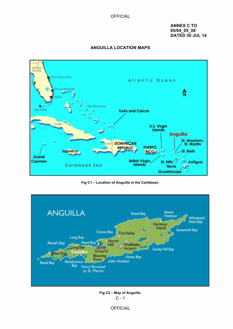
ANGUILLA LOCATION MAPS
Fig C1 – Location of Anguilla in the Caribbean.
Fig C2 – Map of Anguilla.

OFFICIAL
C - 2
OFFICIAL
Intentionally blank
OFFICIAL
D - 1
OFFICIAL
ANNEX D TO 65/04_05_08 DATED 30 JUL 14
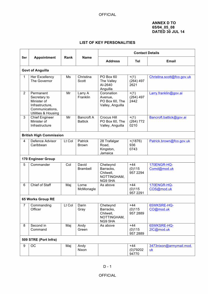
LIST OF KEY PERSONALITIES
Ser Appointment Rank Name Contact Details
Address Tel Email
Govt of Anguilla
1 Her Excellency The Governor
Ms Christina Scott
PO Box 60 The Valley AI-2640 Anguilla
+(1) (264) 497 2621
2 Permanent Secretary to Minister of Infrastructure, Communications, Utilities & Housing
Mr Larry A Franklin
Coronation Avenue, PO Box 60, The Valley, Anguilla
+(1) (264) 497 2442
3 Chief Engineer Minister of Infrastructure
Mr Bancroft A Battick
Crocus Hill PO Box 60, The Valley, Anguilla
+(1) (264) 772 0210
British High Commission 4 Defence Advisor
Caribbean Lt Col Patrick
Brown 28 Trafalgar Road, Kingston, Jamaica
+(1876) 936 0743
170 Engineer Group 5 Commander Col David
Brambell Chetwynd Barracks, Chilwell, NOTTINGHAM, NG9 5HA
+44 (0)115 957 2294
6 Chief of Staff Maj Lorne McMonagle
As above +44 (0)115 957 2291
65 Works Group RE
7 Commanding Officer
Lt Col Darin Gray
Chetwynd Barracks, Chilwell, NOTTINGHAM, NG9 5HA
+44 (0)115 957 2889
8 Second in Command
Maj Andy Green
As above +44 (0)115 957 2889
509 STRE (Port Infra)
9 OC Maj Andy Nixon
+44 (0)79202 94770

OFFICIAL
D - 2
OFFICIAL
Intentionally blank
OFFICIAL
E - 1
OFFICIAL
ANNEX E TO 65/04_05_08 DATED 30 JUL 14
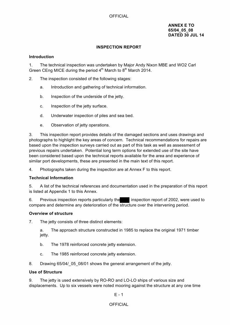
INSPECTION REPORT
Introduction
1. The technical inspection was undertaken by Major Andy Nixon MBE and WO2 Carl Green CEng MICE during the period 4th March to 8th March 2014.
2. The inspection consisted of the following stages:
a. Introduction and gathering of technical information.
b. Inspection of the underside of the jetty.
c. Inspection of the jetty surface.
d. Underwater inspection of piles and sea bed.
e. Observation of jetty operations.
3. This inspection report provides details of the damaged sections and uses drawings and photographs to highlight the key areas of concern. Technical recommendations for repairs are based upon the inspection surveys carried out as part of this task as well as assessment of previous repairs undertaken. Potential long term options for extended use of the site have been considered based upon the technical reports available for the area and experience of similar port developments, these are presented in the main text of this report.
4. Photographs taken during the inspection are at Annex F to this report.
Technical Information
5. A list of the technical references and documentation used in the preparation of this report is listed at Appendix 1 to this Annex.
6. Previous inspection reports particularly the inspection report of 2002, were used to compare and determine any deterioration of the structure over the intervening period.
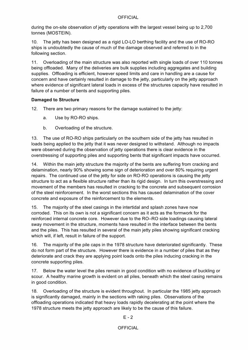
Overview of structure
7. The jetty consists of three distinct elements:
a. The approach structure constructed in 1985 to replace the original 1971 timber jetty.
b. The 1978 reinforced concrete jetty extension.
c. The 1985 reinforced concrete jetty extension.
8. Drawing 65/04/_05_08/01 shows the general arrangement of the jetty.
Use of Structure
9. The jetty is used extensively by RO-RO and LO-LO ships of various size and displacements. Up to six vessels were noted mooring against the structure at any one time
OFFICIAL
E - 2
OFFICIAL
during the on-site observation of jetty operations with the largest vessel being up to 2,700 tonnes (MOSTEIN).
10. The jetty has been designed as a rigid LO-LO berthing facility and the use of RO-RO ships is undoubtedly the cause of much of the damage observed and referred to in the following section.
11. Overloading of the main structure was also reported with single loads of over 110 tonnes being offloaded. Many of the deliveries are bulk supplies including aggregates and building supplies. Offloading is efficient, however speed limits and care in handling are a cause for concern and have certainly resulted in damage to the jetty, particularly on the jetty approach where evidence of significant lateral loads in excess of the structures capacity have resulted in failure of a number of bents and supporting piles.
Damaged to Structure
12. There are two primary reasons for the damage sustained to the jetty:
a. Use by RO-RO ships.
b. Overloading of the structure.
13. The use of RO-RO ships particularly on the southern side of the jetty has resulted in loads being applied to the jetty that it was never designed to withstand. Although no impacts were observed during the observation of jetty operations there is clear evidence in the overstressing of supporting piles and supporting bents that significant impacts have occurred.
14. Within the main jetty structure the majority of the bents are suffering from cracking and delamination, nearly 90% showing some sign of deterioration and over 80% requiring urgent repairs. The continued use of the jetty for side on RO-RO operations is causing the jetty structure to act as a flexible structure rather than its rigid design. In turn this overstressing and movement of the members has resulted in cracking to the concrete and subsequent corrosion of the steel reinforcement. In the worst sections this has caused delamination of the cover concrete and exposure of the reinforcement to the elements.
15. The majority of the steel casings in the intertidal and splash zones have now corroded. This on its own is not a significant concern as it acts as the formwork for the reinforced internal concrete core. However due to the RO–RO side loadings causing lateral sway movement in the structure, moments have resulted in the interface between the bents and the piles. This has resulted in several of the main jetty piles showing significant cracking which will, if left, result in failure of the support.
16. The majority of the pile caps in the 1978 structure have deteriorated significantly. These do not form part of the structure. However there is evidence in a number of piles that as they deteriorate and crack they are applying point loads onto the piles inducing cracking in the concrete supporting piles.
17. Below the water level the piles remain in good condition with no evidence of buckling or scour. A healthy marine growth is evident on all piles, beneath which the steel casing remains in good condition.
18. Overloading of the structure is evident throughout. In particular the 1985 jetty approach is significantly damaged, mainly in the sections with raking piles. Observations of the offloading operations indicated that heavy loads rapidly decelerating at the point where the 1978 structure meets the jetty approach are likely to be the cause of this failure.

OFFICIAL
E - 3
OFFICIAL
19. The majority of the slabs in the jetty approach are also showing signs of distress, with 25% of all slabs requiring urgent repairs. Dynamic loading caused by overloaded vehicles traveling at speed is the likely cause of this damage.
20. The surface of the jetty has a number of defects although there is no evidence to suggest that they are detrimental to the structural integrity of the jetty. The majority being caused by point impact loads and tracked vehicles operating on the jetty. Damage to the edge of the jetty has been caused by RO-RO ramps which rise up to the jetty concentrating the load onto a point at the edge. Lateral movement of the ships have further eroded this edge concrete. Steel angles and plates have been added along the edges but significant damage to these and the concrete was observed during the study by a ships ramp catching the edge of the steel and ripping it from the concrete.
Repairs Previously Undertaken
21. Following the 2002 report, structural repairs to a number of sections of the jetty structure have been undertaken. A review of the repairs and any subsequent deterioration has been undertaken. The conclusion of this is that in the majority of cases the repairs have held and represent a good investment in the prolongation of the structures life.
Recommended Repairs
22. The main elements for repair have been broken down into the following areas:
a. Cracking to piles and bents over piles.
b. Cracking and delamination to bents, centre of section.
c. Cracking and delamination to soffit of slabs.
d. Repairs to fenders and berthing bollards.
e. Surface repairs including edge repairs.
Cracking to Piles and Bents over Piles.
23. In order to prevent failure of the pile through cracking it is necessary to re-establish rigidity at the pile / bent intersection. It is proposed that pile caps doweled into the bents can achieve both protection and stiffening of the pile whilst providing the rigidity required to resist impact loads. Similar methods were used successfully in the 2002 repairs and in all cases have provided sound connections.
Cracking and Delamination to Bents, Centre of Section.
24. Where horizontal cracking of the bents has occurred it will be necessary to remove the delaminated concrete to expose the steel all round, cleaning of the steel to European Standard EN 1504 Repair of Concrete Structures:2009. An assessment of the extent of corrosion of the steel should then be made, where necessary additional reinforcement should be added by fixing to the existing steel.
Cracking and Delamination to Soffit of Slabs.
25. In most cases soffit repairs can be undertaken by breaking out defective concrete and repairing with an epoxy mortar. However where significant deflection has taken place removal of the complete slab may be necessary.
OFFICIAL
E - 4
OFFICIAL
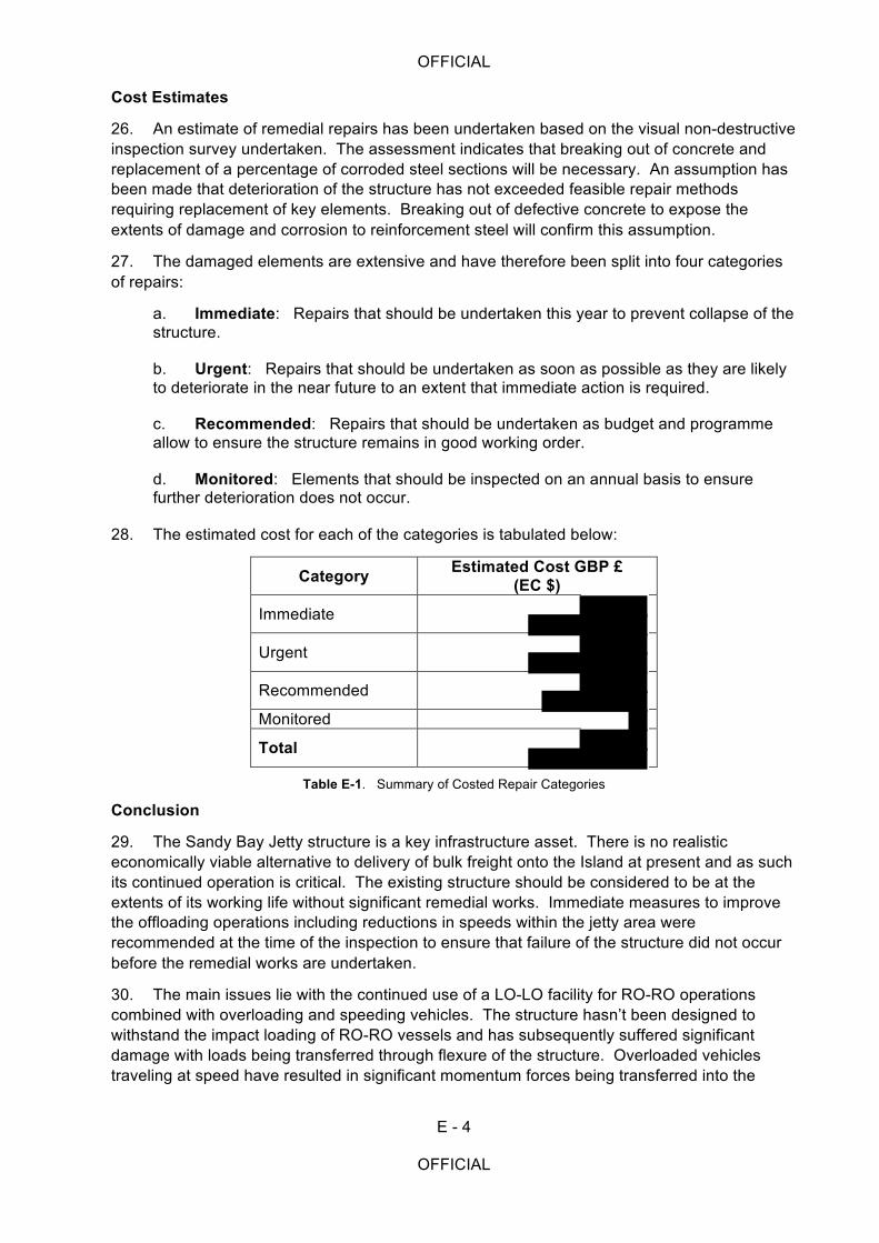
Cost Estimates
26. An estimate of remedial repairs has been undertaken based on the visual non-destructive inspection survey undertaken. The assessment indicates that breaking out of concrete and replacement of a percentage of corroded steel sections will be necessary. An assumption has been made that deterioration of the structure has not exceeded feasible repair methods requiring replacement of key elements. Breaking out of defective concrete to expose the extents of damage and corrosion to reinforcement steel will confirm this assumption.
27. The damaged elements are extensive and have therefore been split into four categories of repairs:
a. Immediate: Repairs that should be undertaken this year to prevent collapse of the structure.
b. Urgent: Repairs that should be undertaken as soon as possible as they are likely to deteriorate in the near future to an extent that immediate action is required.
c. Recommended: Repairs that should be undertaken as budget and programme allow to ensure the structure remains in good working order.
d. Monitored: Elements that should be inspected on an annual basis to ensure further deterioration does not occur.
28. The estimated cost for each of the categories is tabulated below:
Category Estimated Cost GBP £ (EC $)
Immediate
Urgent
Recommended
Monitored
Total
Table E-1. Summary of Costed Repair Categories
Conclusion
29. The Sandy Bay Jetty structure is a key infrastructure asset. There is no realistic economically viable alternative to delivery of bulk freight onto the Island at present and as such its continued operation is critical. The existing structure should be considered to be at the extents of its working life without significant remedial works. Immediate measures to improve the offloading operations including reductions in speeds within the jetty area were recommended at the time of the inspection to ensure that failure of the structure did not occur before the remedial works are undertaken.
30. The main issues lie with the continued use of a LO-LO facility for RO-RO operations combined with overloading and speeding vehicles. The structure hasn’t been designed to withstand the impact loading of RO-RO vessels and has subsequently suffered significant damage with loads being transferred through flexure of the structure. Overloaded vehicles traveling at speed have resulted in significant momentum forces being transferred into the
OFFICIAL
E - 5
OFFICIAL
structure. This has resulted in cracking to the concrete which has caused corrosion of the steel reinforcement and spalling of the cover concrete.
31. It is recommended that urgent works at an estimated cost of are put into place this year. These works concentrate on elements of the structure which show significant cracking and corrosion of the reinforcement steel. Breaking out the defective concrete, replacement of corroded steel and encasement and stiffening of the pile bent intersection form the key components of these works. The recommended operational improvements were put into place immediately by the ports operating authority.
32. The long term operability from Sandy Bay has been considered in a separate report by Reference B, which considers the most economically advantageous option
for this site to be an outer piled extension to the structure with dedicated RO-RO berthing. The restrictions on maximum berthing draft at Sandy Bay will however remain, limiting the size of vessel berthing. It is noted that consideration of a new dedicated RO-RO facility elsewhere on the Island has been considered which would give greater capacity and a dedicated structure for RO-RO vessels with the Sandy Bay structure providing a contingency jetty. However this is outside the scope of the brief for this report.
Appendixes:
1. List of Reference Documentation. 2. Drawings:
65/04_05_08/01 – General Arrangement Drawing 65/04_05_08/02 – Piling & Beam Layout Drawing 65/04_05_08/03 – Damage to Slabs & Beam Soffits 65/04_05_08/04 – Damage to Slabs & Surface of Jetty 65/04_05_08/05 – Jetty Mooring Bollards 65/04_05_08/06 – Sections Bent A to Bent K Jetty Approach 65/04_05_08/07 – Sections Bent L to Bent T Jetty Approach & Main Jetty 65/04_05_08/08 – Sections Bent T+1 to Bent T+8 Main Jetty 65/04_05_08/09 – Sections Bent T+8 to Bent Z Main Jetty 65/04_05_08/10 – Sections Bent Z+1 to Bent Y & Z North Face Main Jetty
3. Summary of Visual Condition Survey & Inspection. 4. Schedule of Repairs. 5. Suggested Repair Methods.

OFFICIAL
E - 6
OFFICIAL
Intentionally blank
OFFICIAL
E1 - 1
OFFICIAL
APPENDIX 1 ANNEX E TO 65/04_05_08 DATED 30 JUL 14
LIST OF REFERENCES
1. British Standards Institution (2005) BS 8110-1:1997 Structural use of concrete – Part 1: Code of practice for design and construction. Milton Keynes: BSI.
2. British Standards Institution (2003) BS 6349-1:2000 Maritime structures – Part 1: Code of practice for general criteria. Milton Keynes: BSI.
3. British Standards Institution (2003) EN 11110- 2- 11000 Part 2 2002 Chapter 8 Hydrodynamic Analysis and Design Conditions.
4. European Standard EN 1504 Repair of Concrete Structures:2009.
5. CIRIA (2010) Use of concrete in the marine environment (C674). London: CIRIA.
6. Concrete Repair Association , The Route to a Successful Repair.
7. British Standards Institution (2008) BS EN 1992-1-1:2004 Eurocode 2: Design of concrete structures – Part 1-1: General rules and rules for buildings. Milton Keynes: BSI.
8. Marine Pile Repairs by Concrete Encasement M Hawkswood Proserve Ltd 2010.
9. Institution of Structural Engineers (2001) Guide to Inspection of underwater structures. London: Institution of Structural Engineers.
10. Thoresen C. A. (2003) Port Designer’s Handbook: Recommendations and Guidelines. London: Thomas Telford.
11. The Repair and Protection of Reinforced Concrete with Sika® In accordance with European Standard EN 1504.
12. US Army Corps of Engineers (2002) Coastal Engineering Manual (EM 1110-2-1100) [online] available at: http://140.194.76.129/publications/eng-manuals/
13. McConnell K, Allsop W. and Cruickshank I (2004) Piers, jetties and related structures exposed to waves. London: Thomas Telford.
14. Corus International Projects Foundations 2007.

OFFICIAL
E1 - 2
OFFICIAL
Intentionally blank
OFFICIAL
E2 - 1
OFFICIAL
APPENDIX 2 ANNEX E TO 65/04_05_08 DATED 30 JUL 14
DRAWINGS
1. This appendix contains drawings of the Road Bay Jetty, showing the damage identified during the visual inspection.
2. The drawings from previous inspection reports particularly the inspection report of 2002, have been used as a template, in order to compare and determine any deterioration of the structure over the intervening period.
3. The following drawings are contained within this appendix:
65/04/_05_08/01 – General Arrangement Drawing 65/04/_05_08/02 – Piling & Beam Layout Drawing 65/04/_05_08/03 – Damage to Slabs & Beam Soffits 65/04/_05_08/04 – Damage to Slabs & Surface of Jetty 65/04/_05_08/05 – Jetty Mooring Bollards 65/04/_05_08/06 – Sections Bent A to Bent K Jetty Approach 65/04/_05_08/07 – Sections Bent L to Bent T Jetty Approach & Main Jetty 65/04/_05_08/08 – Sections Bent T+1 to Bent T+8 Main Jetty 65/04/_05_08/09 – Sections Bent T+8 to Bent Z Main Jetty 65/04/_05_08/10 – Sections Bent Z+1 to Bent Y & Z North Face Main Jetty

OFFICIAL
E2 - 2
OFFICIAL
Intentionally blank
OFFICIAL
E3 - 1
OFFICIAL
APPENDIX 3 ANNEX E TO 65/04_05_08 DATED 30 JUL 14
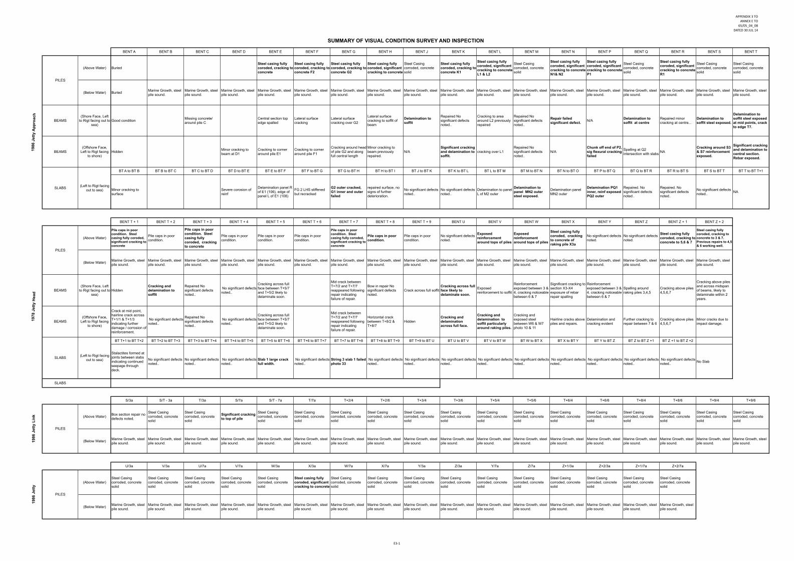
Summary of Visual Condition Survey & Inspection
1. A detailed and comprehensive above surface inspection and below surface visual inspection took place during the period 3 to 7 March 2014 by the following personnel from 509 STRE (Port Infra) in order to assess the structural integrity and residual life of the jetty:
a. Major AP Nixon MBE RE (Construction Engineer and Diver).
b. Warrant Officer 2 C Green RE (Chartered Civil Engineer).
2. The detailed findings of the structural assessment are reported in this Appendix. 3. The format of the Defects Table follows the same layout as the latest previous inspection report, Reference B, so that a direct comparison can be made on the condition of the jetty.

OFFICIAL
E3 - 2
OFFICIAL
Intentionally blank
APPENDIX(3(TOANNEX(E(TO
65/05_04_08DATED(30(JUL(14
E371
SUMMARY OF VISUAL CONDITION SURVEY AND INSPECTION
BENT A BENT B BENT C BENT D BENT E BENT F BENT G BENT H BENT J BENT K BENT L BENT M BENT N BENT P BENT Q BENT R BENT S BENT T
(Above Water) BuriedSteel casing fully coroded, cracking to concrete
Steel casing fully coroded, cracking to concrete F2
Steel casing fully coroded, cracking to concrete G2
Steel casing fully coroded, significant cracking to concrete
Steel Casing corroded, concrete solid
Steel casing fully coroded, cracking to concrete K1
Steel casing fully coroded, significant cracking to concrete L1 & L2
Steel Casing corroded, concrete solid
Steel casing fully coroded, significant cracking to concrete N1& N2
Steel casing fully coroded, significant cracking to concrete P1
Steel Casing corroded, concrete solid
Steel casing fully coroded, significant cracking to concrete R1
Steel Casing corroded, concrete solid
Steel Casing corroded, concrete solid
(Below Water) Buried Marine Growth, steel pile sound.
Marine Growth, steel pile sound.
Marine Growth, steel pile sound.
Marine Growth, steel pile sound.
Marine Growth, steel pile sound.
Marine Growth, steel pile sound.
Marine Growth, steel pile sound.
Marine Growth, steel pile sound.
Marine Growth, steel pile sound.
Marine Growth, steel pile sound.
Marine Growth, steel pile sound.
Marine Growth, steel pile sound.
Marine Growth, steel pile sound.
Marine Growth, steel pile sound.
Marine Growth, steel pile sound.
Marine Growth, steel pile sound.
Marine Growth, steel pile sound.
BEAMS(Shore Face, Left
to Rigt facing out to sea)
Good condition Missing concrete/ around pile C
Central section top edge spalled
Lateral surface cracking
Lateral surface cracking over G2
Lateral surface cracking to soffit of beam
Delamination to soffit
Repaired No significant defects noted..
Cracking to area around L2 previously repaired
Repaired No significant defects noted..
Repair failed significant defect. N/A Delamination to
soffit at centreRepaired minor cracking at centre...
Delamination to soffit steel exposed.
Delamination to soffit steel exposed at mid points, crack to edge T7.
BEAMS(Offshore Face,
Left to Rigt facing to shore)
Hidden Minor cracking to beam at D1
Cracking to corner around pile E1
Cracking to corner around pile F1
Cracking around head of pile G2 and along full central length
Minor cracking to beam previously repaired.
N/ASignificant cracking and delamination to soffit.
cracking over L1Repaired No significant defects noted..
N/AChunk off end of P2, sig flexural cracking failed
Spalling at Q2 intersection with slabs NA
Cracking around S3 & S7 reinforcement exposed.
Significant cracking and delamination to central section. Rebar exposed.
BT A to BT B BT B to BT C BT C to BT D BT D to BT E BT E to BT F BT F to BT G BT G to BT H BT H to BT I BT J to BT K BT K to BT L BT L to BT M BT M to BT N BT N to BT O BT P to BT Q BT Q to BT R BT R to BT S BT S to BT T BT T to BT T+1
Minor cracking to surface
Severe corosion of reinf
Delamination panel R of E1 (106), edge of panel L of E1 (108)
FG 2 LHS stiffened but recracked
G2 outer cracked, G1 inner and outer failed
repaired surface, no signs of further deterioration.
No significant defects noted..
No significant defects noted..
Delamination to panel L of M2 outer
Delamination to panel MN2 outer steel exposed.
Delamination panel MN2 outer
Delamination PQ1 inner, reinf exposed PQ2 outer
Repaired. No significant defects noted..
Repaired. No significant defects noted..
No significant defects noted.. NA
BENT T + 1 BENT T + 2 BENT T + 3 BENT T + 4 BENT T + 5 BENT T + 6 BENT T + 7 BENT T + 8 BENT T + 9 BENT U BENT V BENT W BENT X BENT Y BENT Z BENT Z + 1 BENT Z + 2
(Above Water)
Pile caps in poor condition. Steel casing fully coroded, significant cracking to concrete
Pile caps in poor condition.
Pile caps in poor condition. Steel casing fully coroded, cracking to concrete
Pile caps in poor condition.
Pile caps in poor condition.
Pile caps in poor condition.
Pile caps in poor condition. Steel casing fully coroded, significant cracking to concrete
Pile caps in poor condition.
Pile caps in poor condition.
No significant defects noted.
Exposed reinforcement around tops of piles
Exposed reinforcement around tops of piles
Steel casing fully coroded, cracking to concrete of raking pile X3a
No significant defects noted.
No significant defects noted.
Steel casing fully coroded, cracking to concrete to 5,6 & 7
Steel casing fully coroded, cracking to concrete to 3 & 7. Previous repairs to 4,5 & 6 working well.
(Below Water) Marine Growth, steel pile sound.
Marine Growth, steel pile sound.
Marine Growth, steel pile sound.
Marine Growth, steel pile sound.
Marine Growth, steel pile sound.
Marine Growth, steel pile sound.
Marine Growth, steel pile sound.
Marine Growth, steel pile sound.
Marine Growth, steel pile sound.
Marine Growth, steel pile sound.
Marine Growth, steel pile sound.
Marine Growth, steel pile sound.
Marine Growth, steel pile sound.
Marine Growth, steel pile sound.
Marine Growth, steel pile sound.
Marine Growth, steel pile sound.
Marine Growth, steel pile sound.
BEAMS(Shore Face, Left
to Rigt facing out to sea)
HiddenCracking and delamination to soffit
Repaired No significant defects noted..
No significant defects noted..
Cracking across full face between T+5/7 and T+5/2 likely to delaminate soon.
Mid crack between T+7/2 and T+7/7 reappeared following repair indicating failure of repair.
Bow in repair No significant defects noted.
Crack across full soffitCracking across full face likely to delaminate soon.
Exposed reinforcement to soffit
Reinforcement exposed between 3 & 4. cracking noticeable between 6 & 7
Significant cracking to section X3-X4 exposure of rebar repair spalling
Reinforcement exposed between 3 & 4. cracking noticeable between 6 & 7
Spalling around raking piles 3,4,5
Cracking above piles 4,5,6,7
Cracking above piles and across midspan of beams, likely to delaminate within 2 years.
BEAMS(Offshore Face,
Left to Rigt facing to shore)
Crack at mid point, hairline crack across T+1/1 & T+1/3 indicating further damage / corrosion of reinforcement.
No significant defects noted..
Repaired No significant defects noted..
No significant defects noted..
Cracking across full face between T+5/7 and T+5/2 likely to delaminate soon.
Mid crack between T+7/2 and T+7/7 reappeared following repair indicating failure of repair.
Horizontal crack between T+8/2 & T+8/7
HiddenCracking and delamination across full face.
Cracking and delamination to soffit particularly around raking piles.
Cracking and exposed steel between W6 & W7 photo 10 & 11
Hairline cracks above piles and repairs.
Delamination and cracking evident
Further cracking to repair between 7 & 6
Cracking above piles 4,5,6,7
Minor cracks due to impact damage.
BT T+1 to BT T+2 BT T+2 to BT T+3 BT T+3 to BT T+4 BT T+4 to BT T+5 BT T+5 to BT T+6 BT T+6 to BT T+7 BT T+7 to BT T+8 BT T+8 to BT T+9 BT T+9 to BT U BT U to BT V BT V to BT W BT W to BT X BT X to BT Y BT Y to BT Z BT Z to BT Z +1 BT Z +1 to BT Z +2
Stalactites formed at joints between slabs indicating continued seepage through deck.
No significant defects noted..
No significant defects noted..
No significant defects noted..
Slab 1 large crack full width.
No significant defects noted..
String 3 slab 1 failed photo 33
No significant defects noted..
No significant defects noted..
No significant defects noted..
No significant defects noted..
No significant defects noted..
No significant defects noted..
No significant defects noted..
No significant defects noted..
No significant defects noted.. No Slab
S/3a S/T - 3a T/3a S/7a S/T - 7a T/7a T+2/4 T+2/6 T+3/4 T+3/6 T+5/4 T+5/6 T+6/4 T+6/6 T+8/4 T+8/6 T+9/4 T+9/6
(Above Water) Box section repair no defects noted.
Steel Casing corroded, concrete solid
Steel Casing corroded, concrete solid
Significant cracking to top of pile
Steel Casing corroded, concrete solid
Steel Casing corroded, concrete solid
Steel Casing corroded, concrete solid
Steel Casing corroded, concrete solid
Steel Casing corroded, concrete solid
Steel Casing corroded, concrete solid
Steel Casing corroded, concrete solid
Steel Casing corroded, concrete solid
Steel Casing corroded, concrete solid
Steel Casing corroded, concrete solid
Steel Casing corroded, concrete solid
Steel Casing corroded, concrete solid
Steel Casing corroded, concrete solid
Steel Casing corroded, concrete solid
(Below Water) Marine Growth, steel pile sound.
Marine Growth, steel pile sound.
Marine Growth, steel pile sound.
Marine Growth, steel pile sound.
Marine Growth, steel pile sound.
Marine Growth, steel pile sound.
Marine Growth, steel pile sound.
Marine Growth, steel pile sound.
Marine Growth, steel pile sound.
Marine Growth, steel pile sound.
Marine Growth, steel pile sound.
Marine Growth, steel pile sound.
Marine Growth, steel pile sound.
Marine Growth, steel pile sound.
Marine Growth, steel pile sound.
Marine Growth, steel pile sound.
Marine Growth, steel pile sound.
Marine Growth, steel pile sound.
U/3a V/3a U/7a V/7a W/3a X/3a W/7a X/7a Y/3a Z/3a Y/7a Z/7a Z+1/3a Z+2/3a Z+1/7a Z+2/7a
(Above Water)Steel Casing corroded, concrete solid
Steel Casing corroded, concrete solid
Steel Casing corroded, concrete solid
Steel Casing corroded, concrete solid
Steel Casing corroded, concrete solid
Steel casing fully coroded, significant cracking to concrete
Steel Casing corroded, concrete solid
Steel Casing corroded, concrete solid
Steel Casing corroded, concrete solid
Steel Casing corroded, concrete solid
Steel Casing corroded, concrete solid
Steel Casing corroded, concrete solid
Steel Casing corroded, concrete solid
Steel Casing corroded, concrete solid
Steel Casing corroded, concrete solid
Steel Casing corroded, concrete solid
(Below Water) Marine Growth, steel pile sound.
Marine Growth, steel pile sound.
Marine Growth, steel pile sound.
Marine Growth, steel pile sound.
Marine Growth, steel pile sound.
Marine Growth, steel pile sound.
Marine Growth, steel pile sound.
Marine Growth, steel pile sound.
Marine Growth, steel pile sound.
Marine Growth, steel pile sound.
Marine Growth, steel pile sound.
Marine Growth, steel pile sound.
Marine Growth, steel pile sound.
Marine Growth, steel pile sound.
Marine Growth, steel pile sound.
Marine Growth, steel pile sound.
PILES
1986
Jet
ty A
ppro
ach
1978
Jet
ty H
ead
1986
Jet
ty L
ink
1986
Jet
ty
PILES
SLABS
PILES
SLABS
(Left to Rigt facing out to sea)
PILES
SLABS (Left to Rigt facing out to sea)
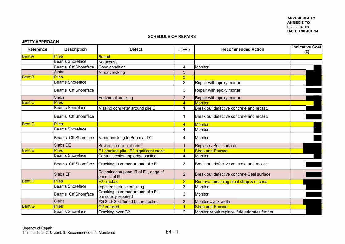
Urgency of Repair1. Immediate, 2. Urgent, 3. Recommended, 4. Monitored. E4 - 1
SCHEDULE OF REPAIRSJETTY APPROACH
Reference Description Defect Urgency Recommended Action Indicative Cost (£)
Bent A Piles BuriedBeams Shoreface No accessBeams Off Shoreface Good condition 4 MonitorSlabs Minor cracking 3
Bent B Piles 3Beams Shoreface 3 Repair with epoxy mortar
Beams Off Shoreface 3 Repair with epoxy mortar
Slabs Horizontal cracking 2 Repair with epoxy mortarBent C Piles 4 Monitor
Beams Shoreface Missing concrete/ around pile C 1 Break out defective concrete and recast.
Beams Off Shoreface 1 Break out defective concrete and recast.
Bent D Piles 4 MonitorBeams Shoreface 4 Monitor
Beams Off Shoreface Minor cracking to Beam at D1 4 Monitor
Slabs DE Severe corosion of reinf 1 Replace / Seal surfaceBent E Piles E1 cracked pile , E2 significant crack 1 Strap and Encase
Beams Shoreface Central section top edge spalled 4 Monitor
Beams Off Shoreface Cracking to corner around pile E1 3 Break out defective concrete and recast.
Slabs EF Delamination panel R of E1, edge of panel L of E1 2 Break out defective concrete Seal surface
Bent F Piles F2 cracked 2 Remove remaining steel strap & encaseBeams Shoreface repaired surface cracking 3 Monitor
Beams Off Shoreface Cracking to corner around pile F1 previously repaired 3 Monitor
Slabs FG 2 LHS stiffened but recracked 2 Monitor crack widthBent G Piles G2 cracked 1 Strap and Encase
Beams Shoreface Cracking over G2 2 Monitor repair replace if deteriorates further.
APPENDIX 4 TO ANNEX E TO 65/05_04_08 DATED 30 JUL 14
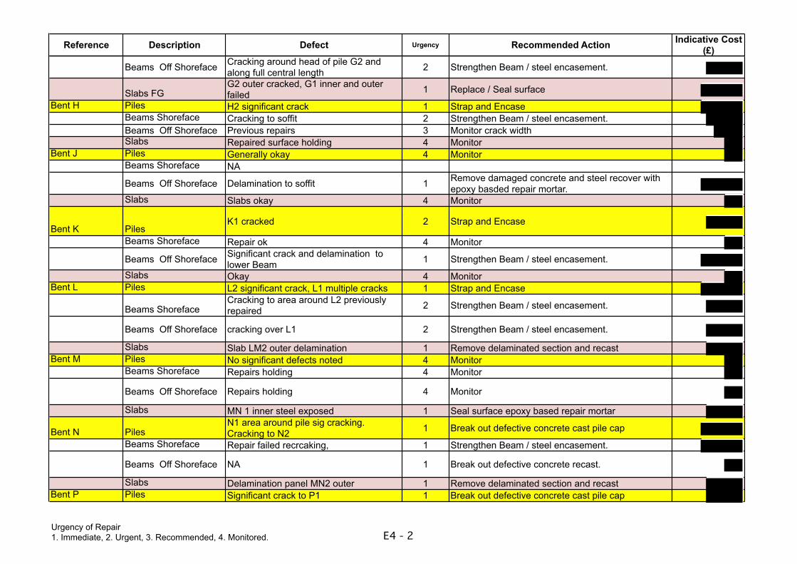
Urgency of Repair1. Immediate, 2. Urgent, 3. Recommended, 4. Monitored. E4 - 2
Reference Description Defect Urgency Recommended Action Indicative Cost (£)
Beams Off Shoreface Cracking around head of pile G2 and along full central length 2 Strengthen Beam / steel encasement.
Slabs FGG2 outer cracked, G1 inner and outer failed 1 Replace / Seal surface
Bent H Piles H2 significant crack 1 Strap and EncaseBeams Shoreface Cracking to soffit 2 Strengthen Beam / steel encasement.Beams Off Shoreface Previous repairs 3 Monitor crack widthSlabs Repaired surface holding 4 Monitor
Bent J Piles Generally okay 4 MonitorBeams Shoreface NA
Beams Off Shoreface Delamination to soffit 1 Remove damaged concrete and steel recover with epoxy basded repair mortar.
Slabs Slabs okay 4 Monitor
Bent K PilesK1 cracked 2 Strap and Encase
Beams Shoreface Repair ok 4 Monitor
Beams Off Shoreface Significant crack and delamination to lower Beam 1 Strengthen Beam / steel encasement.
Slabs Okay 4 MonitorBent L Piles L2 significant crack, L1 multiple cracks 1 Strap and Encase
Beams ShorefaceCracking to area around L2 previously repaired 2 Strengthen Beam / steel encasement.
Beams Off Shoreface cracking over L1 2 Strengthen Beam / steel encasement.
Slabs Slab LM2 outer delamination 1 Remove delaminated section and recastBent M Piles No significant defects noted 4 Monitor
Beams Shoreface Repairs holding 4 Monitor
Beams Off Shoreface Repairs holding 4 Monitor
Slabs MN 1 inner steel exposed 1 Seal surface epoxy based repair mortar
Bent N PilesN1 area around pile sig cracking. Cracking to N2 1 Break out defective concrete cast pile cap
Beams Shoreface Repair failed recrcaking, 1 Strengthen Beam / steel encasement.
Beams Off Shoreface NA 1 Break out defective concrete recast.
Slabs Delamination panel MN2 outer 1 Remove delaminated section and recastBent P Piles Significant crack to P1 1 Break out defective concrete cast pile cap
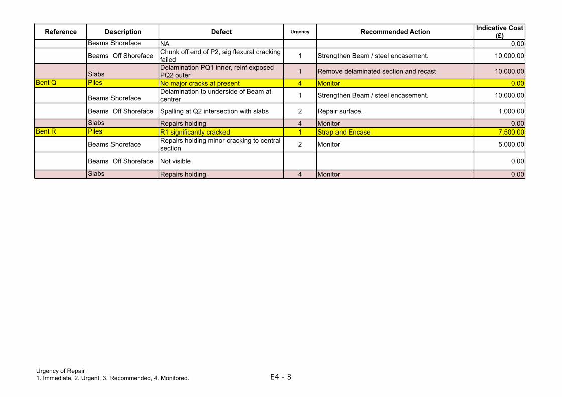
Urgency of Repair1. Immediate, 2. Urgent, 3. Recommended, 4. Monitored. E4 - 3
Reference Description Defect Urgency Recommended Action Indicative Cost (£)
Beams Shoreface NA 0.00
Beams Off Shoreface Chunk off end of P2, sig flexural cracking failed 1 Strengthen Beam / steel encasement. 10,000.00
SlabsDelamination PQ1 inner, reinf exposed PQ2 outer 1 Remove delaminated section and recast 10,000.00
Bent Q Piles No major cracks at present 4 Monitor 0.00
Beams ShorefaceDelamination to underside of Beam at centrer 1 Strengthen Beam / steel encasement. 10,000.00
Beams Off Shoreface Spalling at Q2 intersection with slabs 2 Repair surface. 1,000.00
Slabs Repairs holding 4 Monitor 0.00Bent R Piles R1 significantly cracked 1 Strap and Encase 7,500.00
Beams Shoreface Repairs holding minor cracking to central section 2 Monitor 5,000.00
Beams Off Shoreface Not visible 0.00
Slabs Repairs holding 4 Monitor 0.00
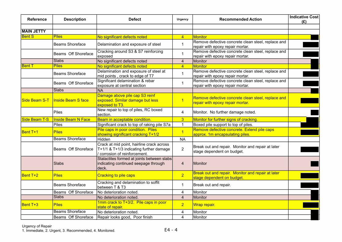
Urgency of Repair1. Immediate, 2. Urgent, 3. Recommended, 4. Monitored. E4 - 4
Reference Description Defect Urgency Recommended Action Indicative Cost (£)
MAIN JETTYBent S Piles No significant defects noted 4 Monitor
Beams Shoreface Delamination and exposure of steel 1 Remove defective concrete clean steel, replace and repair with epoxy repair mortar.
Beams Off Shoreface Cracking around S3 & S7 reinforcing exposed 1 Remove defective concrete clean steel, replace and
repair with epoxy repair mortar.Slabs No significant defects noted 4 Monitor
Bent T Piles No significant defects noted 4 Monitor
Beams Shoreface Delamination and exposure of steel at mid points , crack to edge of T7 1 Remove defective concrete clean steel, replace and
repair with epoxy repair mortar.
Beams Off Shoreface Significant delamination & rebar exposure at central section 1 Remove defective concrete clean steel, replace and
repair with epoxy repair mortar.Slabs NA
Side Beam S-T Inside Beam S faceDamage above pile cap S3 reinf exposed. Similar damage but less exposed to T3.
1 Remove defective concrete clean steel, replace and repair with epoxy repair mortar.
Piles New repair to top of piles, RC boxed section. 4 Monitor. No further damage noted.
Side Beam T-S Inside Beam N Face Beam in acceptable condition. 3 Monitor for further signs of cracking.Piles Significant crack to top of raking pile S7a 1 Boxed pile support to top of piles.
Bent T+1 Piles Pile caps in poor condition. Piles showing significant cracking T+1/2 1 Remove defective concrete. Extend pile caps
approx. 1m encapsulating piles.Beams Shoreface Hidden NA
Beams Off ShorefaceCrack at mid point, hairline crack across T+1/1 & T+1/3 indicating further damage / corrosion of reinforcement.
2 Break out and repair. Monitor and repair at later stage dependent on budget.
SlabsStalactites formed at joints between slabs indicating continued seepage through deck.
4 Monitor
Bent T+2 Piles Cracking to pile caps 2 Break out and repair. Monitor and repair at later stage dependent on budget.
Beams Shoreface Cracking and delamination to soffit between T & T3 1 Break out and repair.
Beams Off Shoreface No deterioration noted. 4 MonitorSlabs No deterioration noted. 4 Monitor
Bent T+3 Piles 1mm crack to T+3/2. Pile caps in poor state of repair. 2 Wrap repair.
Beams Shoreface No deterioration noted. 4 MonitorBeams Off Shoreface Repair looks good, Poor finish 4 Monitor
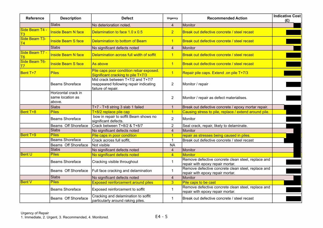
Urgency of Repair1. Immediate, 2. Urgent, 3. Recommended, 4. Monitored. E4 - 5
Reference Description Defect Urgency Recommended Action Indicative Cost (£)
Slabs No deterioration noted. 4 MonitorSide Beam T4 - T3 Inside Beam N face Delamination to face 1.0 x 0.5 2 Break out defective concrete / steel recast
Side Beam T3-T4 Inside Beam S face Delamination to bottom of Beam 1 Break out defective concrete / steel recast
Slabs No significant defects noted 4 MonitorSide Beam T7 - T6 Inside Beam N face Delamination across full width of soffit 1 Break out defective concrete / steel recast
Side Beam T6-T7 Inside Beam S face As above 1 Break out defective concrete / steel recast
Bent T+7 Piles Pile caps poor condition rebar exposed. Significant cracking to pile T+7/3 1 Repair pile caps. Extend .on pile T+7/3
Beams ShorefaceMid crack between T+7/2 and T+7/7 reappeared following repair indicating failure of repair.
2 Monitor / repair
Horizontal crack in same location as above.
2 Monitor / repair as defect materialises.
Slabs T+7 - T+8 string 3 slab 1 failed 1 Break out defective concrete / epoxy mortar repair.Bent T+8 Piles T+8/2 replace pile cap 1 Causing stress to pile, replace / extend around pile.
Beams Shoreface bow in repair to soffit Beam shows no significant defects. 2 Monitor
Beams Off Shoreface Crack between T+8/2 & T+8/7 2 Seal crack, repair, likely to delaminate.Slabs No significant defects noted 4 Monitor
Bent T+9 Piles Pile caps in poor condition 1 repair as stresses being caused in piles.Beams Shoreface Crack across full soffit, 1 Break out defective concrete / steel recastBeams Off Shoreface Not visible NASlabs No significant defects noted 4 Monitor
Bent U Piles No significant defects noted 4 Monitor
Beams Shoreface Cracking visible throughout 1 Remove defective concrete clean steel, replace and repair with epoxy repair mortar.
Beams Off Shoreface Full face cracking and delamination 1 Remove defective concrete clean steel, replace and repair with epoxy repair mortar.
Slabs No significant defects noted 4 MonitorBent V Piles Exposed reinforcement around piles 3 Pile caps to be cast
Beams Shoreface Exposed reinforcement to soffit 1 Remove defective concrete clean steel, replace and repair with epoxy repair mortar.
Beams Off Shoreface Cracking and delamination to soffit particularly around raking piles. 1 Break out defective concrete / steel recast
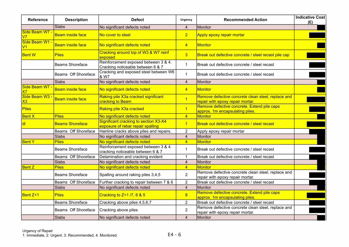
Urgency of Repair1. Immediate, 2. Urgent, 3. Recommended, 4. Monitored. E4 - 6
Reference Description Defect Urgency Recommended Action Indicative Cost (£)
Slabs No significant defects noted 4 MonitorSide Beam W7 - V7 Beam inside face No cover to steel 2 Apply epoxy repair mortar
Side Beam W1 - V1 Beam inside face No significant defects noted 4 Monitor
Bent W Piles Cracking around top of W3 & W7 reinf exposed 3 Break out defective concrete / steel recast pile cap
Beams Shoreface Reinforcement exposed between 3 & 4. Cracking noticeable between 6 & 7 1 Break out defective concrete / steel recast
Beams Off Shoreface Cracking and exposed steel between W6 & W7 1 Break out defective concrete / steel recast
Slabs No significant defects noted 4 MonitorSide Beam W7 - X7 Beam inside face No significant defects noted 4 Monitor
Side Beam W3 - X3 Beam inside face Raking pile X3a cracked significant
cracking to Beam 1 Remove defective concrete clean steel, replace and repair with epoxy repair mortar.
Piles Raking pile X3a cracked 1 Remove defective concrete. Extend pile caps approx. 1m encapsulating piles.
Bent X Piles No significant defects noted 4 Monitor
dl Beams Shoreface Significant cracking to section X3-X4 exposure of rebar repair spalling 1 Break out defective concrete / steel recast
Beams Off Shoreface Hairline cracks above piles and repairs. 2 Apply epoxy repair mortarSlabs No significant defects noted 4 Monitor
Bent Y Piles No significant defects noted 4 Monitor
Beams Shoreface Reinforcement exposed between 3 & 4. cracking noticeable between 6 & 7 1 Break out defective concrete / steel recast
Beams Off Shoreface Delamination and cracking evident 1 Break out defective concrete / steel recastSlabs No significant defects noted 4 Monitor
Bent Z Piles No significant defects noted 4 Monitor
Beams Shoreface Spalling around raking piles 3,4,5 2 Remove defective concrete clean steel, replace and repair with epoxy repair mortar.
Beams Off Shoreface Further cracking to repair between 7 & 6 2 Break out defective concrete / steel recastSlabs No significant defects noted 4 Monitor
Bent Z+1 Piles Cracking to Z+1 /7, 6 & 5 8 Remove defective concrete. Extend pile caps approx. 1m encapsulating piles.
Beams Shoreface Cracking above piles 4,5,6,7 2 Break out defective concrete / steel recast
Beams Off Shoreface Cracking above piles 2 Remove defective concrete clean steel, replace and repair with epoxy repair mortar.
Slabs No significant defects noted 4 Monitor
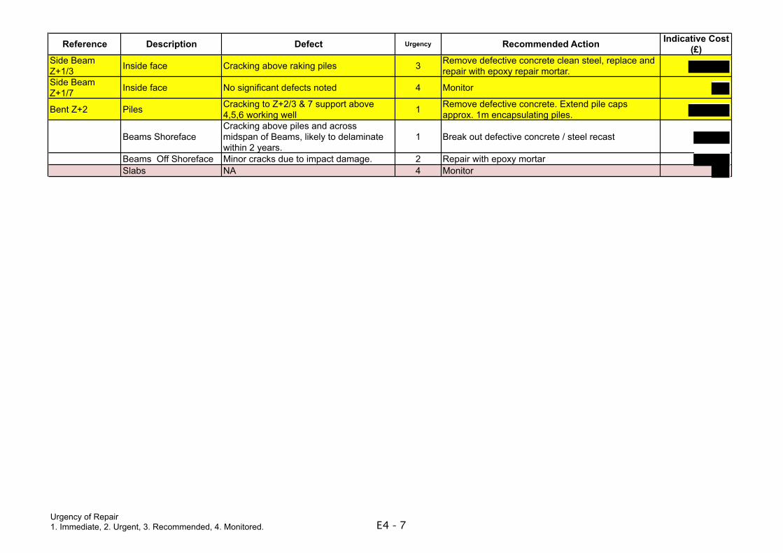
Urgency of Repair1. Immediate, 2. Urgent, 3. Recommended, 4. Monitored. E4 - 7
Reference Description Defect Urgency Recommended Action Indicative Cost (£)
Side Beam Z+1/3 Inside face Cracking above raking piles 3 Remove defective concrete clean steel, replace and
repair with epoxy repair mortar.Side Beam Z+1/7 Inside face No significant defects noted 4 Monitor
Bent Z+2 Piles Cracking to Z+2/3 & 7 support above 4,5,6 working well 1 Remove defective concrete. Extend pile caps
approx. 1m encapsulating piles.
Beams ShorefaceCracking above piles and across midspan of Beams, likely to delaminate within 2 years.
1 Break out defective concrete / steel recast
Beams Off Shoreface Minor cracks due to impact damage. 2 Repair with epoxy mortarSlabs NA 4 Monitor
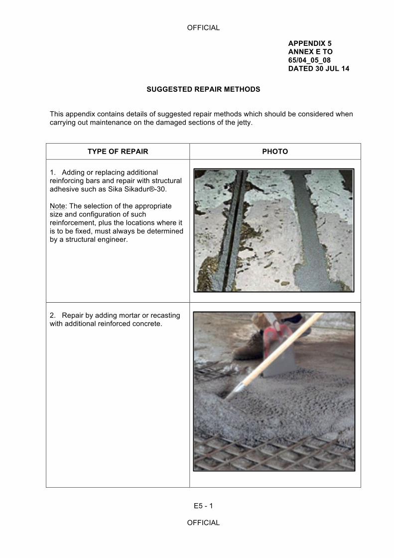
OFFICIAL
E5 - 1
OFFICIAL
APPENDIX 5 ANNEX E TO 65/04_05_08 DATED 30 JUL 14
SUGGESTED REPAIR METHODS
This appendix contains details of suggested repair methods which should be considered when carrying out maintenance on the damaged sections of the jetty.
TYPE OF REPAIR PHOTO 1. Adding or replacing additional reinforcing bars and repair with structural adhesive such as Sika Sikadur®-30. Note: The selection of the appropriate size and configuration of such reinforcement, plus the locations where it is to be fixed, must always be determined by a structural engineer.
2. Repair by adding mortar or recasting with additional reinforced concrete.
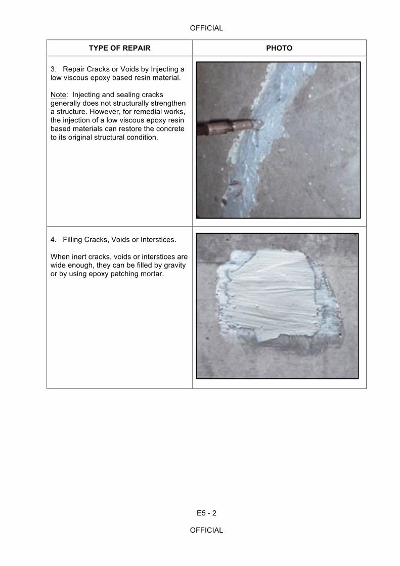
OFFICIAL
E5 - 2
OFFICIAL
TYPE OF REPAIR PHOTO 3. Repair Cracks or Voids by Injecting a low viscous epoxy based resin material. Note: Injecting and sealing cracks generally does not structurally strengthen a structure. However, for remedial works, the injection of a low viscous epoxy resin based materials can restore the concrete to its original structural condition.
4. Filling Cracks, Voids or Interstices. When inert cracks, voids or interstices are wide enough, they can be filled by gravity or by using epoxy patching mortar.
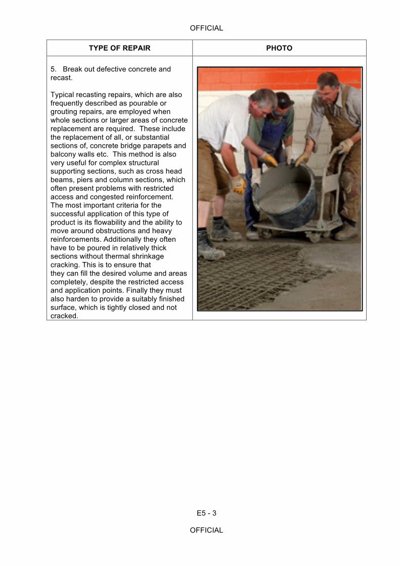
OFFICIAL
E5 - 3
OFFICIAL
TYPE OF REPAIR PHOTO 5. Break out defective concrete and recast. Typical recasting repairs, which are also frequently described as pourable or grouting repairs, are employed when whole sections or larger areas of concrete replacement are required. These include the replacement of all, or substantial sections of, concrete bridge parapets and balcony walls etc. This method is also very useful for complex structural supporting sections, such as cross head beams, piers and column sections, which often present problems with restricted access and congested reinforcement. The most important criteria for the successful application of this type of product is its flowability and the ability to move around obstructions and heavy reinforcements. Additionally they often have to be poured in relatively thick sections without thermal shrinkage cracking. This is to ensure that they can fill the desired volume and areas completely, despite the restricted access and application points. Finally they must also harden to provide a suitably finished surface, which is tightly closed and not cracked.
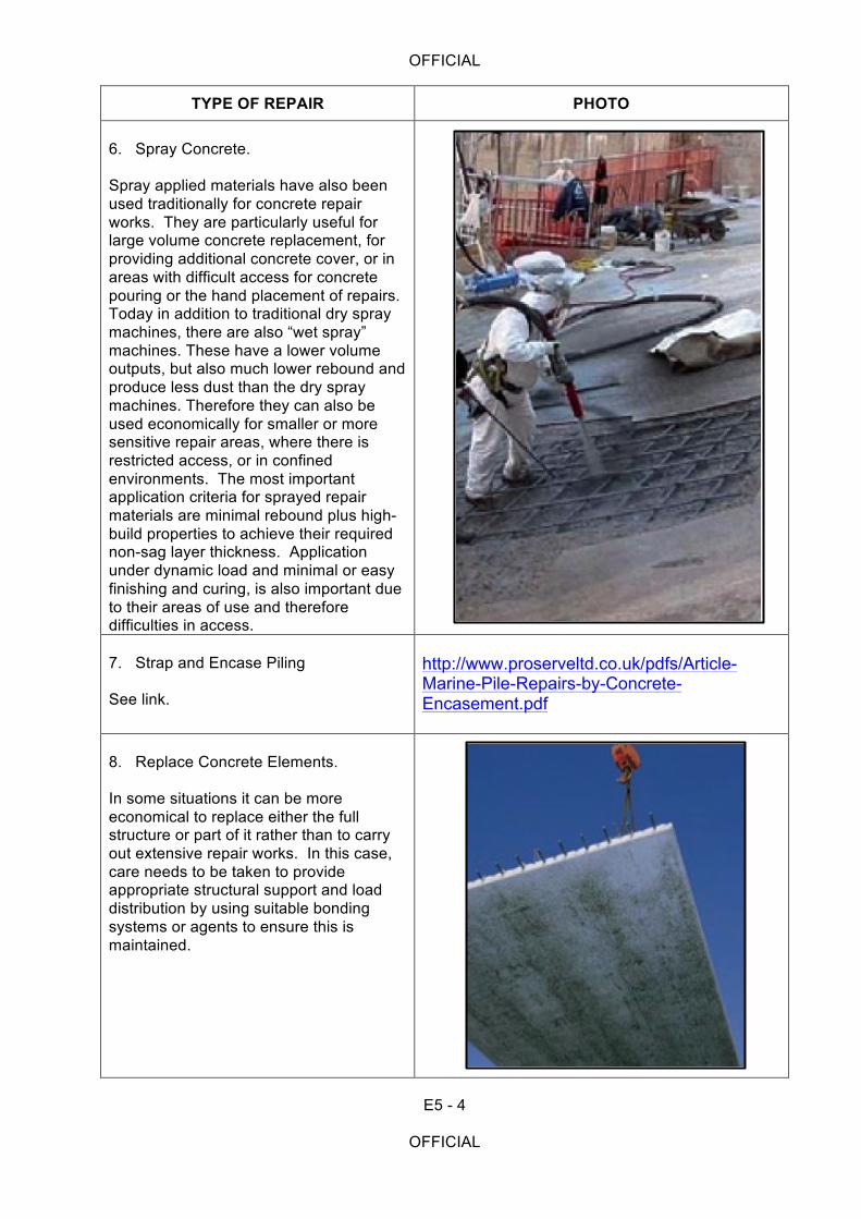
OFFICIAL
E5 - 4
OFFICIAL
TYPE OF REPAIR PHOTO 6. Spray Concrete. Spray applied materials have also been used traditionally for concrete repair works. They are particularly useful for large volume concrete replacement, for providing additional concrete cover, or in areas with difficult access for concrete pouring or the hand placement of repairs. Today in addition to traditional dry spray machines, there are also “wet spray” machines. These have a lower volume outputs, but also much lower rebound and produce less dust than the dry spray machines. Therefore they can also be used economically for smaller or more sensitive repair areas, where there is restricted access, or in confined environments. The most important application criteria for sprayed repair materials are minimal rebound plus high-build properties to achieve their required non-sag layer thickness. Application under dynamic load and minimal or easy finishing and curing, is also important due to their areas of use and therefore difficulties in access.
7. Strap and Encase Piling See link.
http://www.proserveltd.co.uk/pdfs/Article-Marine-Pile-Repairs-by-Concrete-Encasement.pdf
8. Replace Concrete Elements. In some situations it can be more economical to replace either the full structure or part of it rather than to carry out extensive repair works. In this case, care needs to be taken to provide appropriate structural support and load distribution by using suitable bonding systems or agents to ensure this is maintained.
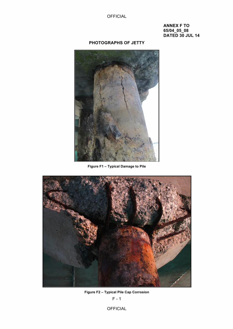
OFFICIAL
F - 1
OFFICIAL
ANNEX F TO 65/04_05_08 DATED 30 JUL 14
PHOTOGRAPHS OF JETTY
Figure F1 – Typical Damage to Pile
Figure F2 – Typical Pile Cap Corrosion
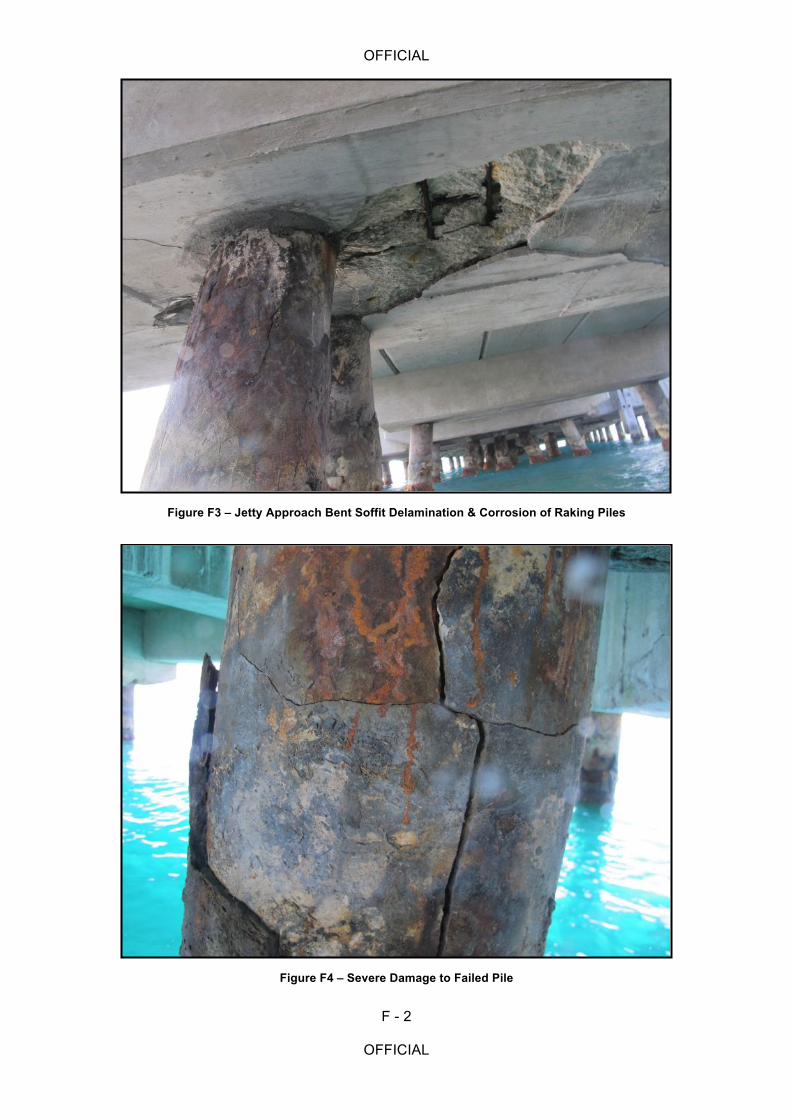
OFFICIAL
F - 2
OFFICIAL
Figure F3 – Jetty Approach Bent Soffit Delamination & Corrosion of Raking Piles
Figure F4 – Severe Damage to Failed Pile
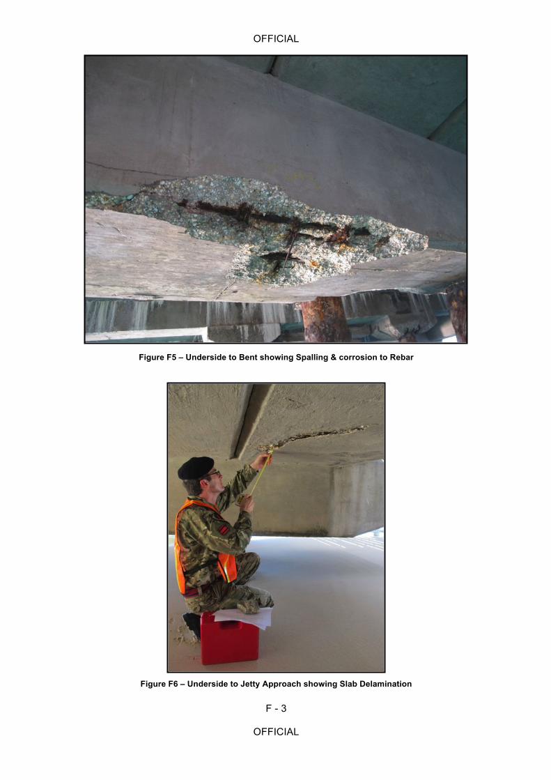
OFFICIAL
F - 3
OFFICIAL
Figure F5 – Underside to Bent showing Spalling & corrosion to Rebar
Figure F6 – Underside to Jetty Approach showing Slab Delamination
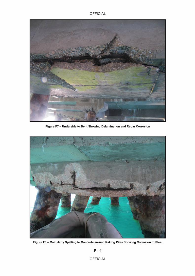
OFFICIAL
F - 4
OFFICIAL
Figure F7 – Underside to Bent Showing Delamination and Rebar Corrosion
Figure F8 – Main Jetty Spalling to Concrete around Raking Piles Showing Corrosion to Steel
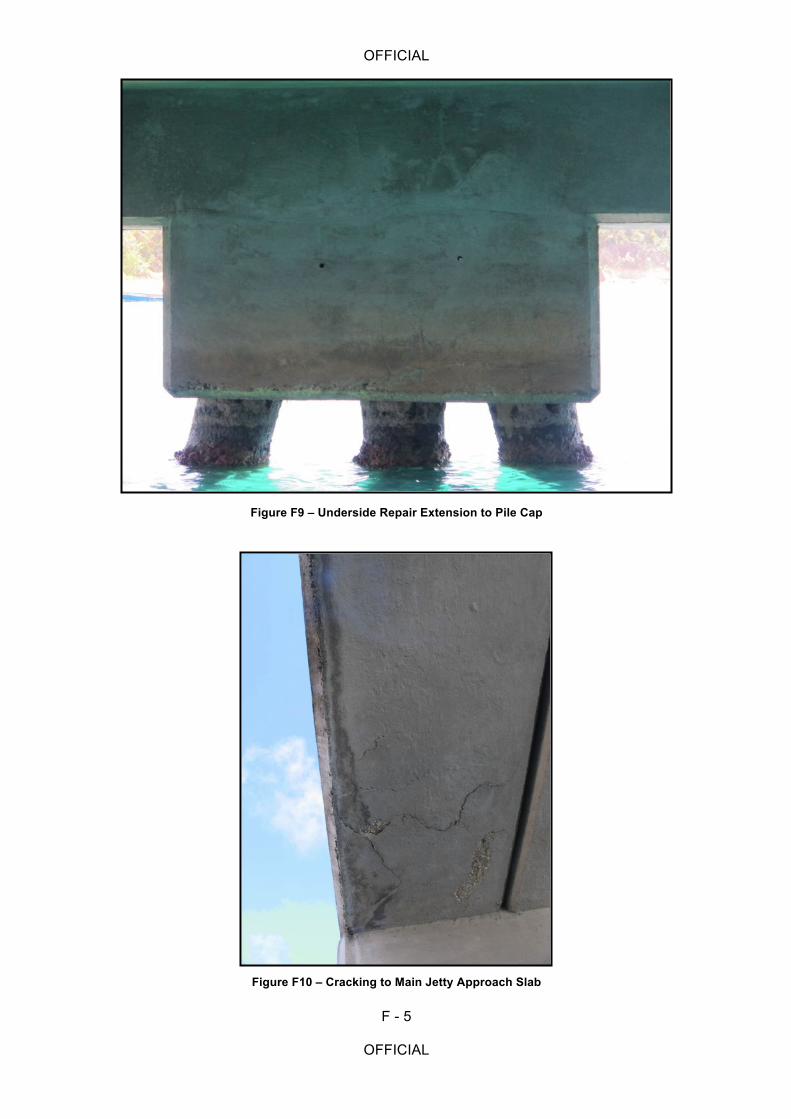
OFFICIAL
F - 5
OFFICIAL
Figure F9 – Underside Repair Extension to Pile Cap
Figure F10 – Cracking to Main Jetty Approach Slab
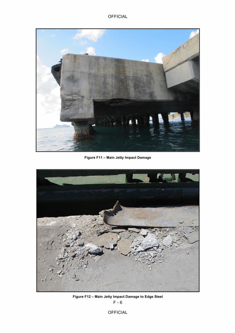
OFFICIAL
F - 6
OFFICIAL
Figure F11 – Main Jetty Impact Damage
Figure F12 – Main Jetty Impact Damage to Edge Steel
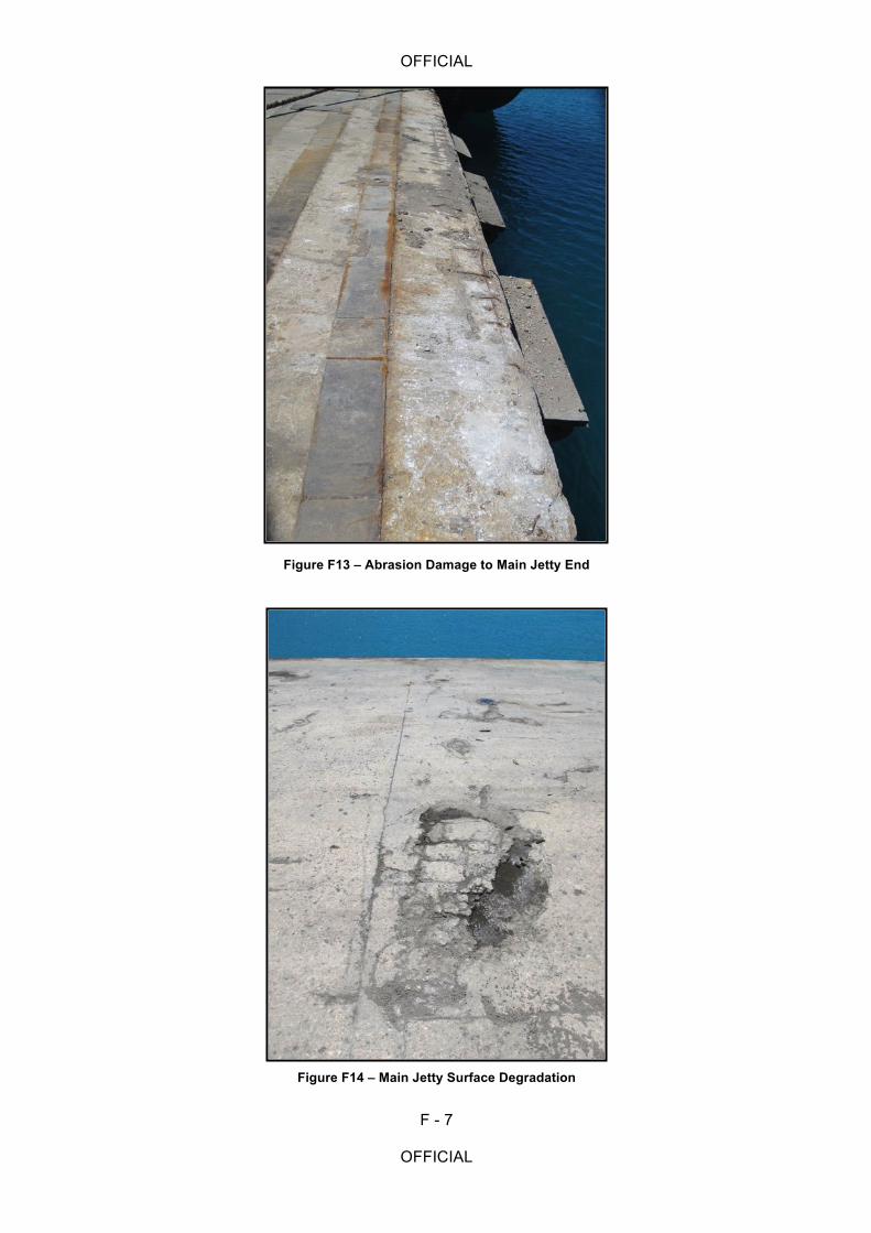
OFFICIAL
F - 7
OFFICIAL
Figure F13 – Abrasion Damage to Main Jetty End
Figure F14 – Main Jetty Surface Degradation
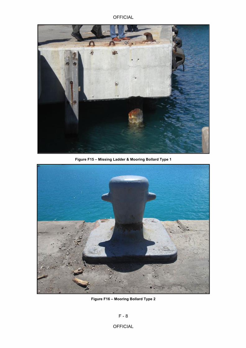
OFFICIAL
F - 8
OFFICIAL
Figure F15 – Missing Ladder & Mooring Bollard Type 1
Figure F16 – Mooring Bollard Type 2
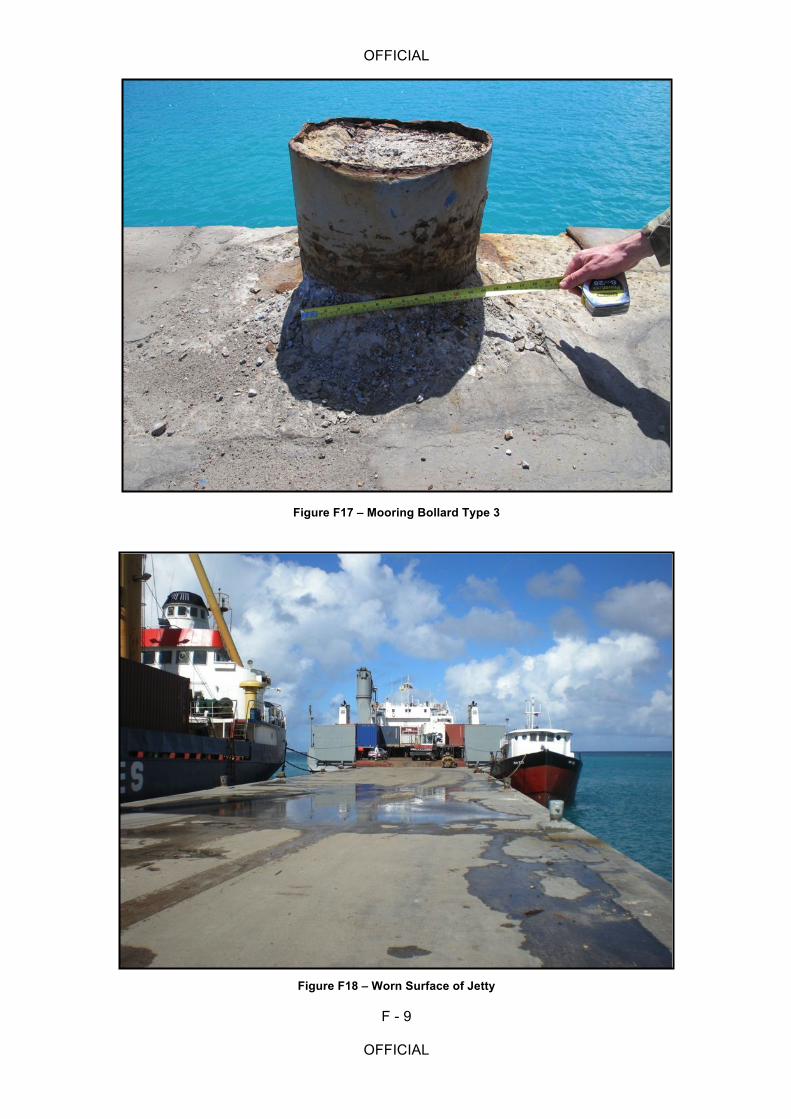
OFFICIAL
F - 9
OFFICIAL
Figure F17 – Mooring Bollard Type 3
Figure F18 – Worn Surface of Jetty