Embed Size (px)
Citation preview

Preliminary Design Report
New Rapid Bay Jetty
Department of Transport, Energy and
Infrastructure
March 2007
Reference 21678-002
Revision 2
Connell Wagner Pty Ltd
ABN 54 005 139 873
55 Grenfell Street
Adelaide
South Australia 5000 Australia
Telephone: +61 8 8237 9777
Facsimile: +61 8 8237 9778
Email: [email protected]
www.conwag.com
id28420453 pdfMachine by Broadgun Software - a great PDF writer! - a great PDF creator! - http://www.pdfmachine.com http://www.broadgun.com
Document Control
Document ID: P:\21678-002-01 RAPID BAY DESIGN\ADMIN\REP\PRELIMINARY DESIGN REPORT.DOC
Rev No Date Revision Details Typist Author Verifier Approver
1 22/01/07 Draft Preliminary Report DHS/BAJ DHS/BAJ
2 02/03/07 Preliminary Report DHS/BAJ DHS/BAJ HCT HCT
A person using Connell Wagner documents or data accepts the risk of:
a) Using the documents or data in electronic form without requesting and checking them for accuracy against the original hard copy
version; and
b) Using the documents or data for any purpose not agreed to in writing by Connell Wagner.

New Rapid Bay Jetty Department of Transport, Energy and Infrastructure
Preliminary Design Report
FILE P:\21678-002-01 RAPID BAY DESIGN\ADMIN\REP\PRELIMINARY DESIGN REPORT.DOC 02 MAR 2007 REVISION 2 PAGE i
Table of Contents
Section Page
1. Introduction 1 1.1 Background 1 1.2 Client�s Requirements 1
2. Planning and Layout 1
3. Occupational Health and Safety 2
4. Design Parameters 2 4.1 Standards 2 4.2 Design life 2 4.3 Structural loads 2
5. Jetty Structure 3 5.1 Deck 3 5.2 Substructure 3 5.3 Divers� Access Stairway 4 5.4 Lighting 4 5.5 Deck Amenities 4 5.6 Materials 4
6. Environmental Issues 5
Appendix A General Arrangement Drawing 2-6763 Sheet 1
Appendix B Performance requirements for M-Lock precast units for Rapid Bay Jetty
Appendix C Lighting Performance Specification
New Rapid Bay Jetty Department of Transport, Energy and Infrastructure
Preliminary Design Report
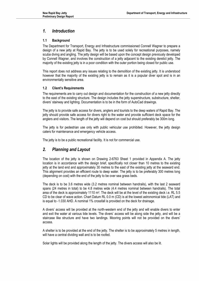
1. Introduction
1.1 Background
The Department for Transport, Energy and Infrastructure commissioned Connell Wagner to prepare a
design of a new jetty at Rapid Bay. The jetty is to be used solely for recreational purposes, namely
scuba diving and angling. The jetty design will be based upon the concept design previously developed
by Connell Wagner, and involves the construction of a jetty adjacent to the existing derelict jetty. The
majority of the existing jetty is in a poor condition with the outer portion being closed for public use.
This report does not address any issues relating to the demolition of the existing jetty. It is understood
however that the majority of the existing jetty is to remain as it is a popular diver spot and is in an
environmentally sensitive area.
1.2 Client�s Requirements
The requirements are to carry out design and documentation for the construction of a new jetty directly
to the east of the existing structure. The design includes the jetty superstructure, substructure, shelter,
divers� stairway and lighting. Documentation is to be in the form of AutoCad drawings.
The jetty is to provide safe access for divers, anglers and tourists to the deep waters of Rapid Bay. The
jetty should provide safe access for divers right to the water and provide sufficient deck space for the
anglers and visitors. The length of the jetty will depend on cost but should preferably be 300m long.
The jetty is for pedestrian use only with public vehicular use prohibited. However, the jetty design
caters for maintenance and emergency vehicle access.
The jetty is to be a public recreational facility. It is not for commercial use.
2. Planning and Layout
The location of the jetty is shown on Drawing 2-6763 Sheet 1 provided in Appendix A. The jetty
location is in accordance with the design brief, specifically not closer than 10 metres to the existing
jetty at the land end and approximately 30 metres to the east of the existing jetty at the seaward end.
This alignment provides an efficient route to deep water. The jetty is to be preferably 300 metres long
(depending on cost) with the end of the jetty to be over sea grass beds.
The deck is to be 3.6 metres wide (3.2 metres nominal between handrails), with the last 2 seaward
spans (24 metres in total) to be 4.8 metres wide (4.4 metres nominal between handrails). The total
area of the deck is approximately 1110 m2. The deck will be at the level of the existing deck i.e. RL 5.5
CD to be clear of wave action. Chart Datum RL 0.0 m (CD) is at the lowest astronomical tide (LAT) and
is equal to -1.030 AHD. A nominal 1% crossfall is provided on the deck for drainage.
A divers� access will be provided at the north-western end of the jetty and will enable divers to enter
and exit the water at various tide levels. The divers� access will be along side the jetty, and will be a
staircase like structure and have two landings. Mooring points will not be provided on the divers�
access.
A shelter is to be provided at the end of the jetty. The shelter is to be approximately 5 metres in length,
will have a central dividing wall and is to be roofed.
Solar lights will be provided along the length of the jetty. The divers access will also be lit.

New Rapid Bay Jetty Department of Transport, Energy and Infrastructure
Preliminary Design Report
FILE P:\21678-002-01 RAPID BAY DESIGN\ADMIN\REP\PRELIMINARY DESIGN REPORT.DOC 02 MAR 2007 REVISION 2 PAGE 2
3. Occupational Health and Safety
The design has taken into account the specific requirements of the principal users. The surface of the
deck will be wood floated concrete which will not be slippery when wet. A 1% crossfall is provided on
the deck for drainage of rainfall. The stair treads and the diving platforms will have open grating to
ensure a free draining non-slip surface. Handrails will be provided along both sides of the jetty and
around the end jetty and on the stairs and platforms for the divers. The hand rail system on the deck is
in accordance with the DTEI Marine Facilities guidelines.
Safety ladders will be placed at 60 metre nominal centres along the length of the jetty in accordance
with AS 4997. The provision of other safety aids such as life buoys will be to DTEI requirements.
4. Design Parameters
4.1 Standards
The preliminary design for the jetty generally complies with AS4997 Guidelines for the Design of
Maritime Structures, except as discussed later for the deck. Loading combinations are as outlined in
AS 4997 and AS 1170.0.
4.2 Design life
A design life of 40 years has been specified by DTEI. As the divers� platform is subject to high cyclic
loading due to wave action, a reduced design life of 10 years has been assumed.
4.3 Structural loads
Live Loads
The deck load classification is Class 5 in accordance with AS 4997. This is applicable for public
boardwalks and promenades, and caters for pedestrian crowd loading and light vehicles such as
maintenance and emergency vehicles. The following live loads will apply:
Uniformly distributed load 5kPa
Concentrated load 20 kN at 1.8m centres on an area of 150mm x 150mm each.
Diving platforms and access 2.5 kPa (in accordance with AS1657)
Wave loads
The design wave information is based upon information previously provided by DTEI and the maximum
non breaking wave that could occur at the site from the applicable water depth. Wave loads on the
structure were therefore calculated based on the following:
Annual probability of exceedence 1/200 (Equivalent to a 50 year design life)
Wave crest level crest RL 4.0 CD
Design wave height 5.6 m
Design water level RL 1.2 CD
Effective water depth for maximum wave 8.4 m
Wave period 12 sec
Due to the lack of guidance in Australian Codes, wave forces have been calculated in accordance with
the Coastal Engineering Manual prepared by the U.S. Army Corps of Engineers.
Current loads
Current loads due to tidal movements are considered to be non critical.
Wind loads
Wind loads have been determined from AS 4997 and AS 1170.2 for Region A1, Terrain category 2
The wind loads have been assumed to be concurrent with the wave loads in accordance with AS 4997.

New Rapid Bay Jetty Department of Transport, Energy and Infrastructure
Preliminary Design Report
FILE P:\21678-002-01 RAPID BAY DESIGN\ADMIN\REP\PRELIMINARY DESIGN REPORT.DOC 02 MAR 2007 REVISION 2 PAGE 3
Seismic loads
Seismic loads have been based on AS 1170.4 for a Type �I� structure
Importance Factor 1.0
Site Factor 1.0
Acceleration Coefficient 0.1
Design Category B
Seismic loads are considered to be non critical
5. Jetty Structure
5.1 Deck
As per the concept design, a Rocla M-Lock bridge deck system has been adopted for the deck of the
jetty. This precast concrete bridge deck system allows for rapid construction and has been specifically
developed for bridges. It has been used extensively for rural road projects. It is currently being used in
the design of a very similar structure to the Rapid Bay Jetty on Hamilton Island, Queensland.
The jetty cross-section is to consist of 3 No. 1.2 metre wide units giving an overall width of 3.6 metres.
In accordance with DTEI requirements, hand rails are to be fixed to the top of the deck resulting in a
clear width between rails of approximately 3.2 metres. A cross-section of the deck is shown on
Drawing 2-6763 Sheet 1 in Appendix A.
A limitation of the proprietary M-Lock system is that the cover to reinforcing can be no greater than
35 mm. As this system is a standardised design, the cover is fixed by the size of the steel moulds and
the size of the reinforcement required. The following table summarises the cover requirements of
various Australian Standards based upon a concrete strength of 50 MPa for precast concrete with
intense vibration.
AS 4997 AS 5100.5 AS 3600
Exposure environment Class Cover Class Cover Class Cover
Air borne sea spray zone, C1 45 B2 35 B2 25
Splash zone C2 60 C 50 C 40
Design life 25 years 100 years 40 � 60 years
AS 4997 Guidelines for the design of maritime structures
AS 5100.5 Bridge design � Concrete
AS 3600 Concrete structures
The deck units are in the spray zone, i.e. above the splash zone. AS 4997 however requires exposed
soffits of structures over the sea to be classified as category C2.
As can be seen above, ambiguity exists in the above codes in regard to concrete cover requirements
and related design lives for structures in a marine environment. As such, a review of the above codes
has been undertaken by Connell Wagner�s Materials specialist in regard to achieving a 40 year design
life with a cover of 35 mm. Following this review, a performance specification for concrete has been
developed in order to achieve a concrete with low porosity and provide sufficient resistance against
chloride ion penetration. This concrete mix will result in the Rocla M-Lock units having a design life of
40 years with a cover of 35 mm. A copy of the code review and concrete performance criteria is
provided in Appendix B.
5.2 Substructure
The proposed piles are 610mm diameter 12.7mm thick steel piles driven into the sea bed. No recent
geotechnical data is present however the records from the construction of the original jetty indicate that

New Rapid Bay Jetty Department of Transport, Energy and Infrastructure
Preliminary Design Report
FILE P:\21678-002-01 RAPID BAY DESIGN\ADMIN\REP\PRELIMINARY DESIGN REPORT.DOC 02 MAR 2007 REVISION 2 PAGE 4
rock is likely to be found close to the surface for the majority of the length of the jetty. It is anticipated
that piles founded in rock will need an embedment length of 2 - 4 metres. The jetty piles are to be
raked at 1 in 5 to provide lateral stability of the pile bents. The piles will have a protective coating
applied which will extend to 1.0 metres below sea bed level.
A precast concrete headstock will be placed over the piles. This will incorporate voids to allow a
monolithic in-situ concrete connection to be made with the piles. The reinforcement and concrete will
extend about 1.8 metres into the pile as shown on Drawing 2-6763 Sheet 1. The concrete cover in the
pile headstocks and reinforcement requirements will comply with AS4997.
5.3 Divers� Access Stairway
The divers� access stairway will be located at the north-western end along side the jetty. The access
stairway will have 2 landings, one at deck level and the other approximately 1.5 metres above high tide
level. The end of the stairway will be 0.5 metres below the lowest astronomical tide level (-0.5m CD). A
ladder 1.5 metres long will be provided at the end of the stairway.
The divers� access stairway is to be designed for a live load of 2.5 kPa. The stairway will also be
designed for wave and wind loadings. Due to the high cyclic loading of wave action durability of the
platforms will be an issue. The design life has been assumed as 10 years, however their performance
will be influenced strongly by the magnitude, duration and frequency of major storms.
The platforms will have open mesh decking to reduce the wave loads and to provide a free draining
non slip surface. The platforms will be detailed to enable easy replacement of any damaged
components.
Mooring points will not be provided on the divers� stairway. Signage will be required to discourage
mooring of vessels.
5.4 Lighting
Grid connected solar lighting is proposed for the jetty and the divers� access stairway. The level of
lighting will be suitable for pedestrian access along the jetty. A performance specification for the jetty
lighting is provided in Appendix C.
5.5 Deck Amenities
Safety ladders will be installed along the length of the jetty at 60 metre centres. The aluminium ladders
will extend to 500mm below chart datum.
A galvanised steel Monowills handrail will be provided along the full length of the deck.
A small shelter will be provided at the end of the jetty. The shelter is approximately 5 metres long, and
will have a central dividing wall and solid end walls to provide protection from the wind.
5.6 Materials
Material selection is based on constructability and durability in a marine environment. Concrete
elements will generally be precast in forms subject to intense vibration using 50MPa strength concrete.
The steel piles have been selected for their strength and durability. They will have a high quality
marine grade protective coating applied to them to improve their durability.
The handrails will be galvanised steel whilst the divers� stairway access framing and other metal work
will be marine grade aluminium. The decks for the divers� platforms will be FRP (fibre reinforced
plastic). These are non-corrosive in a marine environment. All connections will be fully seal welded or
bolted using marine grade 316 stainless steel. Separation between dissimilar metals will be made to
ensure that bi-metallic actions do not occur.

New Rapid Bay Jetty Department of Transport, Energy and Infrastructure
Preliminary Design Report
FILE P:\21678-002-01 RAPID BAY DESIGN\ADMIN\REP\PRELIMINARY DESIGN REPORT.DOC 02 MAR 2007 REVISION 2 PAGE 5
6. Environmental Issues
The jetty is to be constructed in a sensitive marine environment and therefore the preliminary design
has allowed for construction techniques that minimise environmental damage. The main concern is
damage to the sea grass beds near the head of the jetty. The preliminary design of the jetty uses steel
piles driven into the seabed supporting a precast concrete deck. The environmental impact of piling
needs to be considered. There are two options for the installation of the piles. For both options the
precast concrete deck units would be erected progressively off completed sections of the jetty. Thus
deck placement would have little impact on the marine environment.
Although the piles could be driven progressively from the completed deck the slow construction
sequence and difficult logistics in getting material out along the deck are likely to make that method
prohibitively expensive. The deck units could not be placed until the precast pile caps had been placed
and the infill concrete had cured. This would require a 3-4 week cycle per span, or about a 2 year
construction period. Floating plant anchored to the sea bed would still be required to support the guide
for the raking piles.
For piling off floating plant the plant would have to be anchored to the seabed. There would be some
damage where the anchors are placed. The number of anchor points and the frequency of their
relocation will need to be optimised by the contractor. If the anchors are only moved a few times long
lead lines would be required and may drag on the bottom thereby causing more damage than if the
anchors are moved more frequently and the lead lines keep short. The number of anchors could be
reduced if the barge was moored on one side to the existing jetty. This would only be possible if the
jetty has sufficient structural integrity to handle the loads. The floating plant would have to be moved to
a safe mooring Wirrina Cove in the event of poor weather necessitating the raising of the anchors.
The aerial photo of the site indicates that the majority of the pile driving occurs along the rocky
shoreline and sandy sea bed. It is therefore recommended that piling should be carried out off floating
plant initially and the impact of the anchors and tie lines monitored. If it is considered that the
environmental impacts are acceptable piling off the floating plant should be continued in the sea grass
beds.
Therefore installation of the piles and pile caps from floating plant is recommended from both an
environmental and economic point of view. There would be no delays for curing of concrete. The much
reduced construction period would also reduce the risk of accidental environmental damage. A
comprehensive construction environmental management plan would be mandatory.
No provisions have been made for collecting rainfall run off from the deck for onshore disposal as there
will be very little vehicle traffic and the risk of washing harmful pollutants into the sea is very low.
No provision has been made for fish cleaning facilities.

Appendix A
General Arrangement Drawing 2-6763 Sheet 1

SOUTH
AU
S T R A L
IA
Marine Facilities Section
Issue
Job No.
Date
Date
Date
Date
Connell Wagner Pty Ltd
South Australia 5000 Australia55 Grenfell Street Adelaide
Facsimile:Telephone:
Email:
ABN 54 005 139 873
+61 8 8237 9777+61 8 8237 9778
Approved
Designed
Verified
Drawn
PRELIMINARY DESIGN
id372068828 pdfMachine by Broadgun Software - a great PDF writer! - a great PDF creator! - http://www.pdfmachine.com http://www.broadgun.com

Appendix B
Performance requirements for M-Lock precast units for Rapid Bay
Jetty

Performance requirements for M-Lock precast units for the Rapid Bay Jetty
General
The M-lock precast concrete units proposed for use at the new Rapid Bay Jetty are reinforced concrete elements
with a minimum concrete cover of 35 mm from the soffit side. The units are installed on concrete headstocks
using Grade 316 stainless steel bolts and fixings.
According to AS 4997, the exposure condition for the soffit is C2 and of the topside of deck slab is C1. For
precast concrete, AS 4997 provides the following requirements for 50 MPa Grade concrete:
For topside of deck slab: 50 MPa/45 mm cover
For soffit side of deck slab: 50 MPa/60 mm cover
Cementitious content greater than 40 kg/m3
Water-to-binder ratio not more than 0.40
Drying shrinkage @ 56 days less than 600 x 10-6 mm/mm
Water cured for not less than 7 days
Minimum reinforcement diameter 16 mm for slabs
Maximum allowable reinforcement steel stress at serviceability limit state ~ 175 MPa, 160 MPa and 150 MPa
for 16 mm, 20 mm and 24 mm diameter bars respectively
In addition to the above, AS 4997 notes further that �A design life of 25 years can be expected where the above
tables are adopted for cover to reinforcement. Engineering judgment is required where a longer service life is
required. �.�. Although additional measures are mentioned, there are no specific procedures or methodologies
recommended to achieve longer service life in AS 4997 in terms of requirements for concrete characteristics.
The M-lock precast units with a cover of 35 mm, therefore, would not satisfy the requirements of AS 4997 for
exposure classification C2. Strictly speaking, with 35 mm of 50 MPa concrete cover, AS 4997 suggests that the
design life would be much less than 5 years since the cover requirement for a 5 year design life is 45 mm with 50
MPa concrete (see Note 4 and using Table 6.5).
Practical experience of marine concrete structures would suggest that AS 4997 is extremely conservative. This
may be justifiable for irreplaceable marine structures of national/international importance or marine structures
whose loss of serviceability would lead to substantial economic/personal loss.
In this particular case, an approach to durability of marine concrete is presented. This approach is based on
current understandings of performance requirements relevant to reinforced marine concrete. With the exception of
concrete cover which is constrained at 35 mm minimum for the M-Lock system, other requirements given in AS
4997 for concrete will be retained as minimum benchmarks.
Requirements of concrete suitable for M-Lock precast decking system
In a marine splash zone, the main requirement of concrete performance is its resistance to chloride ion
penetration. This is based on the consideration that corrosion of steel reinforcement is acknowledged as the main
cause of loss of durability of marine concrete structures. There is no apparent reason to suggest that this would
be different for Rapid Bay Jetty.
Procedures for prediction of service life of concrete with respect to chloride induced corrosion of steel
reinforcement have been established for sometime. In this case, the service lives of marine concrete with 35 mm
cover are estimated under different scenarios. The objective of this particular exercise is to determine a set of
parameters from which performance criteria of concrete are derived. The performance criteria (besides the
minimum levels set in AS 4997) are used to maximise the probability of achieving a 50 year service life of precast
concrete in a marine environment with 35 mm minimum cover.
The results of the chloride ion penetration analysis into concrete are summarised in the following Table for an
exposure period of 50 years.
id28647453 pdfMachine by Broadgun Software - a great PDF writer! - a great PDF creator! - http://www.pdfmachine.com http://www.broadgun.com

Case
No
Chloride Diffusion
Coefficient (m2.s-1) after 28 days of exposure
m Co max % w/w
concrete
Time to
reach Co (y)
Chloride concentration at 35
mm depth (w/w concrete)
1 3 x 10-12 0.1 0.8 5 0.52
2 2 x 10-12 0.1 0.8 5 0.46
3A 1 x 10-12 0.1 0.8 5 0.35
4 3 x 10-12 0.2 0.8 5 0.44
5 2 x 10-12 0.2 0.8 5 0.37
6A 1 x 10-12 0.2 0.8 5 0.24
7 3 x 10-12 0.3 0.8 5 0.34
8 2 x 10-12 0.3 0.8 5 0.27
9A 1 x 10-12 0.3 0.8 5 0.14
10 3 x 10-12 0.4 0.8 5 0.24
11 2 x 10-12 0.4 0.8 5 0.17
12A 1 x 10-12 0.4 0.8 5 0.07
3B 1 x 10-12 0.1 0.7 5 0.31
6B 1 x 10-12 0.2 0.7 5 0.21
9B 1 x 10-12 0.3 0.7 5 0.12
12B 1 x 10-12 0.4 0.7 5 0.055
3C 1 x 10-12 0.1 0.6 5 0.26
6C 1 x 10-12 0.2 0.6 5 0.18
9C 1 x 10-12 0.3 0.6 5 0.105
12C 1 x 10-12 0.4 0.6 5 0.045
With consideration to the cover of 35 mm and a high relative humidity in concrete (most probably > 95%), the
chloride concentration of 0.08 % is chosen as the level of chloride which can initiate corrosion of steel
reinforcement. It should be noted that a chloride threshold level of 0.05% would be more appropriate for a smaller
concrete cover whilst a higher chloride level of 0.1% and greater is more reasonable for a larger concrete cover.
This consideration is based on the pattern of development of corrosion rate of steel at similar chloride
concentrations but at different concrete cover depth and/or at different relative humidity.
The results of the chloride analyses given above suggest clearly that in order to attain a design life of 50 years
with 35 mm concrete cover, the following requirements are necessary:
Chloride diffusion coefficient (at 28 days) of concrete mix D28 days should be about 1 x 10-12 m2.s-1
The value of m should be about 0.4
The m value is used for characterising the time-dependent characteristic of chloride diffusion coefficient. It is a
factor dependent on the concrete mix proportion and particularly on the composition of the binder. For normal
Portland cement concrete, this factor � as measured in the laboratory or as observed on real structures � is in the
range of 0.3 or less. The observation of m greater than 0.3 for Portland cement concrete is very rare. On the
other hand, the m factor for blended cement concrete is generally in the range of 0.5 (m ~ 0.8 has been
reported/observed for blended cement concretes).
The requirement of m ~ 0.4 and greater implies that the M-Lock precast unit must be made from blended cement.
The requirement of D28 days ~ 1 x 10-12 m2.s-1 suggest that the water-to-binder ratio of the concrete should not be
higher than 0.4 and would be in the range of 0.350 to 0.375.
For a 25% fly ash concrete mix, it is possible to produce a 50 MPa grade concrete (average strength ~ 55 to 58
MPa), using about 335 kg/m3 of portland cement, 115 kg/m3 of fine grade fly ash (total binder content of 450
kg/m3) and water-binder-ratio of 0.375 (up to about 170 l/m3 of water). The resistance to fly ash concrete will be
further assured by specifying a water-binder-ratio 0.35
In addition to the above, in a precast situation where a high early strength is required, it is suggest further that
amorphous silica/silica fume should be considered in the concrete mix. The optional inclusion of silica fume � at
about 22 kg/m3 or ~ 5% to total binder of 450 kg/m3 would lead to achievement of early strength favourable for
stripping as well as improved abrasion erosion resistance. The presence of silica fume will also ensure that the m

factor will be at least 0.4 as required. It is emphasised that the inclusion of silica fume is optional and is suggested
for obtaining early age strength when considered necessary.
The overall concrete mix would be as follow:
Blended cement with binder content not less than 450 kg/m3
Blended cement should contain 25% fine grade fly ash (112 kg/m3) and optional 5% silica fume (22 kg/m3) or
equivalent amorphous silica when required
W/B 0.35
Water content of the concrete should not be more than 170 l/m3
The m value of such concrete would be well above the required 0.4.
It should be noted that the above are suggested concrete mix design parameters for consideration. The objective
is to match the probability of a achieving a 40 year design life to that achieved by designing the structure in strict
accordance with recognised design codes. Actual mix design/proportioning should be left with the concrete
supplier.
Performance criteria
The following are suggested performance criteria for concrete, which will provide sufficient resistance to chloride
ion penetration for maximising the probability of achieving a design life of 40 years in marine splash zone with 35
mm cover.
Wet concrete
Cementitious content: - minimum
- maximum
400 kg/m3
500 kg/m3
Cementitious binder materials GP Portland cement
with 25% FA
Maximum water/cement ratio 0.35
Maximum aggregate size 20 mm
Slump to AS 1012 Part 3 prior to adding admixture agreed mix value 10 mm
Slump to AS 1012 Part 3 after adding admixture ≥120 mm, ≤ 220 mm or as agreed
Air content ≤ 2%
Hardened concrete
Compressive strength
28-day required quality control strength (Q)
Measured in accordance with AS 1012 Part 9
7 day strength
56 day strength
not < 50 MPa
≥ 70% of 28 day strength
≥ 60 MPa
Maximum drying shrinkage measured in accordance with AS
1012 Part 13:
approved trial mix at 28 days
in situ concrete at 28 days
470 microstrain
500 microstrain
Curing requirements
Wet curing
Strength ≥ nominated 7 day strength
Temperature rise
Maximum temperature
Maximum temperature rise
≤ 65˚C
≤ 35˚C
Chloride Permeability (ASTM C1202)
at 7days
at 28 days
at 56 days
Chloride Permeability (CSIRO�s modified ASTM C 1202)
measured at 56 days
<2000 coulombs
<1500 coulombs
<1000 coulombs
< 500 coulombs
In the above table, the performance criteria related to chloride permeability are based on indirect testing methods
of ASTM C1202 and CSIRO�s Modified ASTM C 1202. The criteria given are aimed at achieving a concrete with

favourable pattern of development of chloride diffusion coefficient with time and low porosity. It is recommended
that a laboratory trial concrete mix be carried out based upon the design concrete mix.

Appendix C
Lighting Performance Specification

Rapid Bay Jetty Lighting Performance Specification for D&C
General Description
This component of the project comprises the design and construction of solar, grid-connected
public lighting to the new jetty. This includes liaison with ETSA Utilities to provide a new dual
direction metered supply to the new jetty.
Lighting Design Solution
The design and installation shall as a minimum meet the requirements of:
1. The Service Rules and Conditions of Supply by ETSA.
2. Australian Standard AS 3000 � Wiring Rules.
3. Australian Standard AS 1158 � Lighting for Roads and Public Spaces.
4. Building Code of Australia.
5. Insurance Council of Australia Regulations.
6. Occupational Health and Safety Act.
The final lighting design solution shall meet the requirements of AS/NZS 1158, Category P4 as
a minimum. High Pressure Sodium (HPS) lamps shall be utilised for the light source.
Lighting is to be controlled via a Photoelectric (PE) cell to ensure the lighting remains on
between dusk and dawn only. The PE cell shall be a single item located in an appropriate
location, rather than integral to each luminaire.
The final design shall take into consideration both the safety for the initial installation, but also
the future maintainability of the light fittings including lamp replacement. It shall be possible to
maintain the light fittings from the jetty itself without the need for expensive, cumbersome
equipment. Details of the proposed maintenance strategy shall be submitted for review with the
design.
Consideration shall be given to vandalism for all components of the installation both by way of
access prevention to critical components and strength & resistance to accessible items such as
the pole and luminaire itself.
General Luminaire Pole Construction Requirements
Light poles shall be mounted directly to the jetty and shall be designed to house all required
control gear. Access panels shall be provided at low level for pole cable connections and fuses.
Poles, light fittings and connections shall be designed and constructed for a minimum design
life of 25 years within the marine environment.
Solar Panels
Solar panels are to be provided on each pole, orientated to provide the maximum average sun
hours over the calendar year for the installed location. A minimum of 2x80W polycrystalline
solar panels shall be installed on each pole, however the final design solution shall recover a
minimum of 80% energy used to operate the lamps. A larger array shall be provided to meet
this requirement should it be necessary for the chosen design.
All required inverters and controls shall be installed within each pole in a location easily
accessible for maintenance. A minimum inverter efficiency of 95% shall be maintained.
id28629250 pdfMachine by Broadgun Software - a great PDF writer! - a great PDF creator! - http://www.pdfmachine.com http://www.broadgun.com

Consideration also needs to be given to the prevention of vandalism. Appropriate measures
shall be taken in the design to discourage permanent resting of wildlife.
A minimum warranty for the design life quoted above shall be provided for the solar installation.
Cabling
All cabling shall be appropriately rated for both current carrying capacity and a maximum
voltage drop of 5% to the final luminaire from the point of supply. All cabling shall be
appropriately protected within conduit and be appropriately concealed within the jetty structure.
ETSA Connection & Metering
ETSA Utilities has indicated that a private supply is its preference for the new jetty lighting.
Confirmation of available supply at the site shall be confirmed in the first instance with ETSA
(there appears to be a supply to the existing jetty lighting).
Undertake all aspects of the ETSA connection enquiry and inform the client of the associated
costs for their action. Coordinate the construction and programming of the supply to the new
jetty. This shall include all requirements for the installation of dual direction metering.
A new metering enclosure shall be provided at a suitable location for the supply to the new jetty
lighting. This enclosure shall be constructed of marine grade stainless steel and be
appropriately sealed for its location. The enclosure shall contain dual direction metering,
supply fuses (to be confirmed by ETSA), circuit protection to the new lighting circuits and
associated controls for operation by the PE cell.
Documentation
The following design documentation shall be submitted as a minimum for approval prior to
construction:
1. Detailed modelling results showing lux levels including details of the maximum, minimum,
average and uniformity
2. Plan showing proposed pole locations
3. Technical details of the proposed luminaires
4. Technical details of the proposed solar system, including energy recovery calculations
5. Pole details, including proposed connection method
6. Details of the final power supply arrangement to the jetty
7. Construction details of the metering enclosure
8. Details of the proposed ongoing maintenance strategy
Upon completion of the project �As Built� documentation shall be compiled for the lighting
system which shall include all of the above in final format.