Embed Size (px)
Citation preview

Road Service Quick Reference Guide 2016-2017 Jaguar F-Type
Quality and Education Services AAA Automotive 1000 AAA Drive
Heathrow, FL 32746
March 31, 2017
1
Index
Quick Specifications and Information 2 Start/Stop Switch Operation 2 Hood Release 3 Trunk Lid Release 3 Electronic Parking Brake (EPB) 4 Towing, Loading and Transporting 4 Selecting Neutral 7 Neutral-Shift Interlock Override 7 Jacking and Tire Service 9 Fuel Service 11 Jump-Start Procedure 11 Electronic Key 13 Lockout Procedure 14
Important Notice: This publication should not be used while driving. The procedures in this publication should only be used by qualified and trained personnel. This Road Service Quick Reference Guide was developed to highlight some model-specific information and common procedures for servicing or towing this vehicle. It is not all-inclusive. For complete information: The applicable vehicles owner’s manual and the AAA Towing and Service Manual should be used in conjunction with this guide. The procedures recommended and described in this guide are effective methods of performing light service and towing operations. Some of these procedures require the use of auxiliary equipment specially designed for the purpose. The auxiliary equipment should be used when and as recommended and whenever the trained operator deems it appropriate. It is important to read the various WARNINGS, CAUTIONS and NOTES in this manual in order to minimize the risk of personal injury to service personnel and or customers and to avoid procedures which may damage the vehicle or render it unsafe. It is also important to understand that these warnings, cautions and notes are not exhaustive. Neither AAA nor the auto and towing equipment manufacturers could possibly know, evaluate and advise the reader of all conceivable methods of towing or evaluate individual situations. Accordingly, anyone who uses a towing procedure must be thoroughly convinced that neither personal safety nor vehicle safety will be jeopardized by the selected procedure. AAA is not responsible for changes made by the manufacturers to the vehicles or their recommendations. Important changes in procedures and updates will be furnished to all manual users at AAACampus.aaa.biz.
2
QUICK SPECIFICATIONS AND INFORMATION: Available Drivelines: RWD, AWD
F-Type Coupe Base Curb Weight Front Axle Weight Rear Axle Weight Manual Trans RWD: 3,492 lbs. 2,095 lbs. 1,397 lbs. Auto Trans RWD: 3,536 lbs. 2,122 lbs. 1,414 lbs. Auto Trans AWD: 3,814 lbs. 2,288 lbs. 1,526 lbs. Note: Weights represent the heaviest optioned models available. F-Type Convertible Base Curb Weight Front Axle Weight Rear Axle Weight Manual Trans RWD: 3,514 lbs. 2,108 lbs. 1,406 lbs. Auto Trans RWD: 3,558 lbs. 2,135 lbs. 1,423 lbs. Auto Trans AWD: 3,847 lbs. 2,308 lbs. 1,539 lbs. Note: Weights represent the heaviest optioned models available.
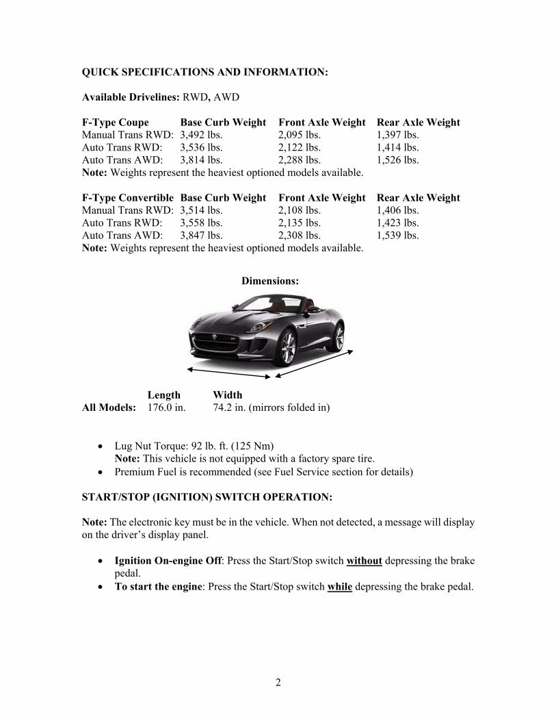
Length Width
All Models: 176.0 in. 74.2 in. (mirrors folded in)
Lug Nut Torque: 92 lb. ft. (125 Nm) Note: This vehicle is not equipped with a factory spare tire.
Premium Fuel is recommended (see Fuel Service section for details) START/STOP (IGNITION) SWITCH OPERATION: Note: The electronic key must be in the vehicle. When not detected, a message will display on the driver’s display panel.
Ignition On-engine Off: Press the Start/Stop switch without depressing the brake pedal.
To start the engine: Press the Start/Stop switch while depressing the brake pedal.
Dimensions:
3
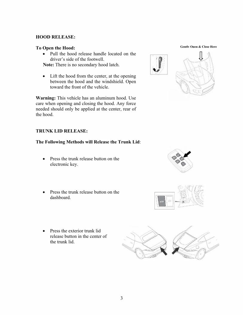
HOOD RELEASE: To Open the Hood:
Pull the hood release handle located on the driver’s side of the footwell.
Note: There is no secondary hood latch. Lift the hood from the center, at the opening
between the hood and the windshield. Open toward the front of the vehicle.
Warning: This vehicle has an aluminum hood. Use care when opening and closing the hood. Any force needed should only be applied at the center, rear of the hood. TRUNK LID RELEASE: The Following Methods will Release the Trunk Lid:
Press the trunk release button on the electronic key.
Press the trunk release button on the
dashboard. Press the exterior trunk lid
release button in the center of the trunk lid.
Gently Open & Close Here
4
ELECTRONIC PARKING BRAKE (EPB): Operation: Note: The EPB can be applied with the ignition On or Off. The ignition must be On to release the EPB.
To apply the EPB: Lift the EPB switch briefly. To release the EPB: Depress the brake pedal and
press down on the EPB switch briefly. Note:
The EPB applies automatically when Park is selected or when the ignition is switched Off.
To release the parking brake when the battery is discharged, connect a booster pack to the jump-start pins in the engine compartment and operate the EPB switch normally.
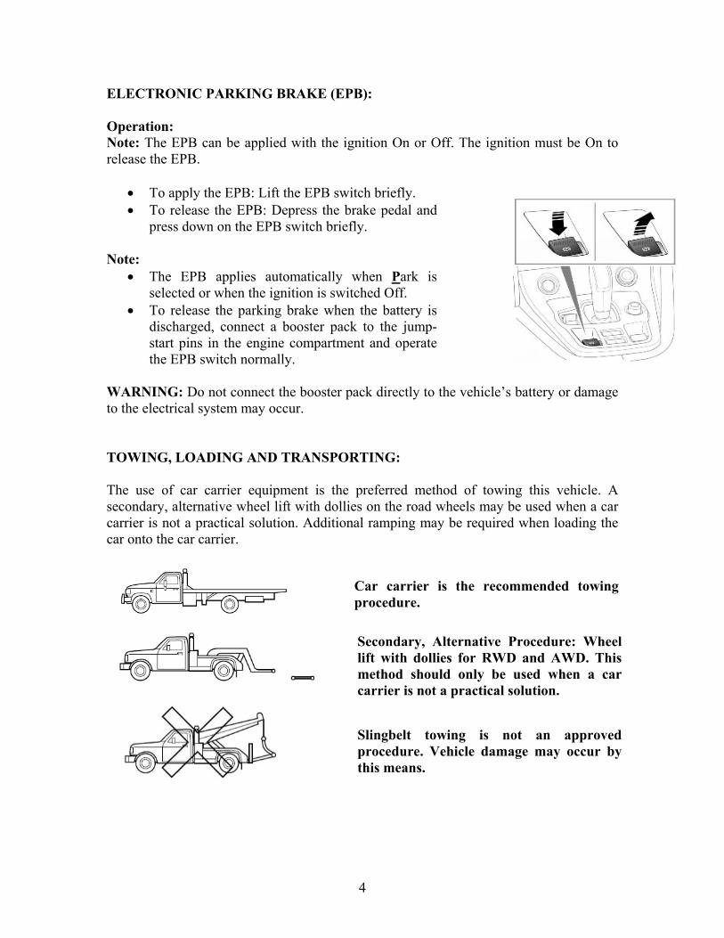
WARNING: Do not connect the booster pack directly to the vehicle’s battery or damage to the electrical system may occur. TOWING, LOADING AND TRANSPORTING: The use of car carrier equipment is the preferred method of towing this vehicle. A secondary, alternative wheel lift with dollies on the road wheels may be used when a car carrier is not a practical solution. Additional ramping may be required when loading the car onto the car carrier.
Secondary, Alternative Procedure: Wheel lift with dollies for RWD and AWD. This method should only be used when a car carrier is not a practical solution.
Car carrier is the recommended towing procedure.
Slingbelt towing is not an approved procedure. Vehicle damage may occur by this means.
5
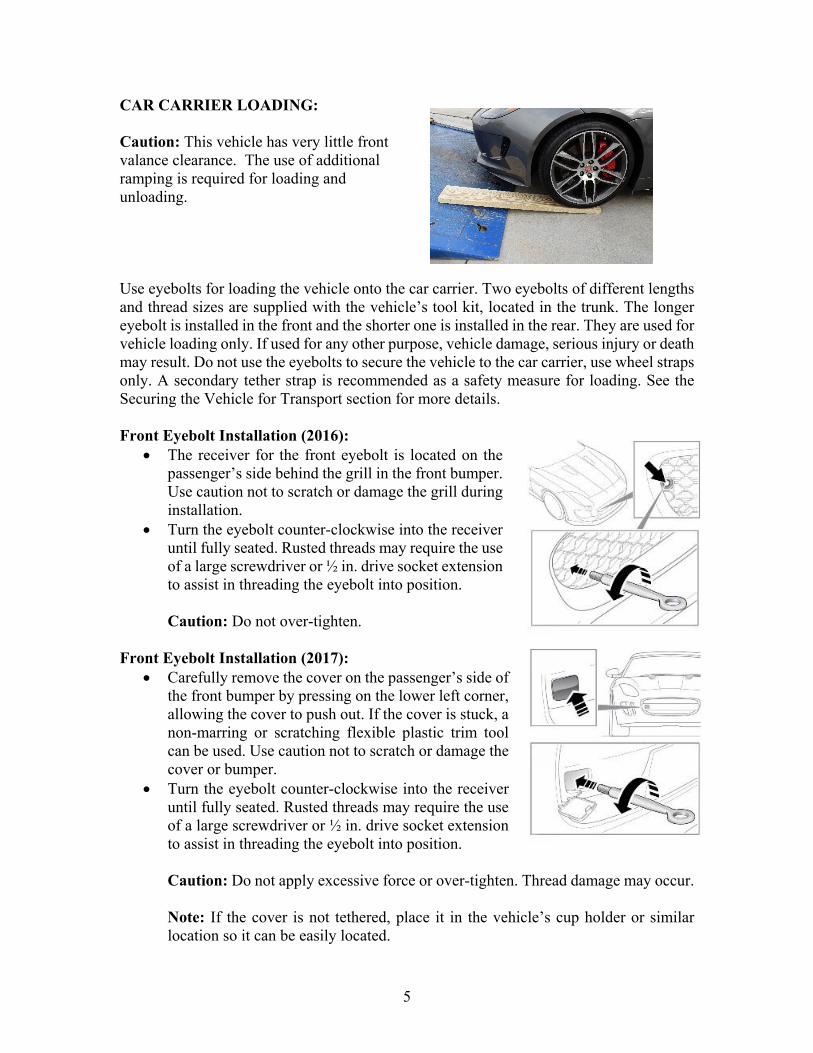
CAR CARRIER LOADING: Caution: This vehicle has very little front valance clearance. The use of additional ramping is required for loading and unloading. Use eyebolts for loading the vehicle onto the car carrier. Two eyebolts of different lengths and thread sizes are supplied with the vehicle’s tool kit, located in the trunk. The longer eyebolt is installed in the front and the shorter one is installed in the rear. They are used for vehicle loading only. If used for any other purpose, vehicle damage, serious injury or death may result. Do not use the eyebolts to secure the vehicle to the car carrier, use wheel straps only. A secondary tether strap is recommended as a safety measure for loading. See the Securing the Vehicle for Transport section for more details. Front Eyebolt Installation (2016):
The receiver for the front eyebolt is located on the passenger’s side behind the grill in the front bumper. Use caution not to scratch or damage the grill during installation.
Turn the eyebolt counter-clockwise into the receiver until fully seated. Rusted threads may require the use of a large screwdriver or ½ in. drive socket extension to assist in threading the eyebolt into position. Caution: Do not over-tighten.
Front Eyebolt Installation (2017):
Carefully remove the cover on the passenger’s side of the front bumper by pressing on the lower left corner, allowing the cover to push out. If the cover is stuck, a non-marring or scratching flexible plastic trim tool can be used. Use caution not to scratch or damage the cover or bumper.
Turn the eyebolt counter-clockwise into the receiver until fully seated. Rusted threads may require the use of a large screwdriver or ½ in. drive socket extension to assist in threading the eyebolt into position. Caution: Do not apply excessive force or over-tighten. Thread damage may occur. Note: If the cover is not tethered, place it in the vehicle’s cup holder or similar location so it can be easily located.
6
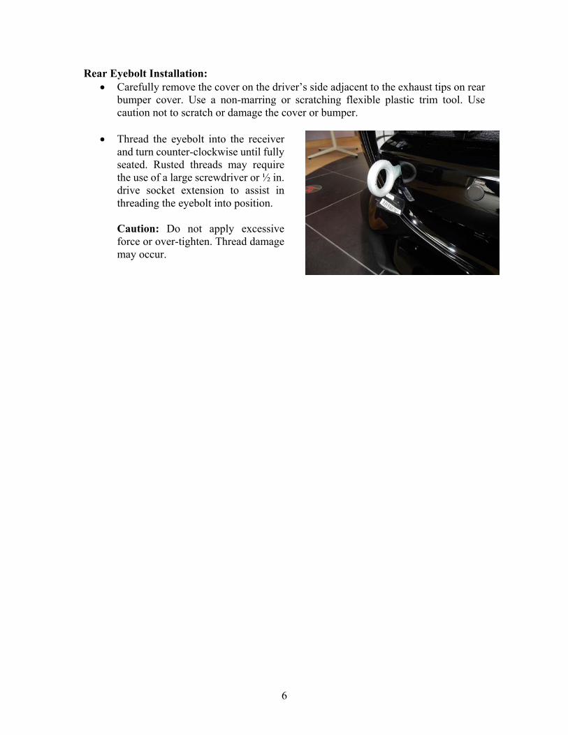
Rear Eyebolt Installation: Carefully remove the cover on the driver’s side adjacent to the exhaust tips on rear
bumper cover. Use a non-marring or scratching flexible plastic trim tool. Use caution not to scratch or damage the cover or bumper.
Thread the eyebolt into the receiver and turn counter-clockwise until fully seated. Rusted threads may require the use of a large screwdriver or ½ in. drive socket extension to assist in threading the eyebolt into position. Caution: Do not apply excessive force or over-tighten. Thread damage may occur.
7
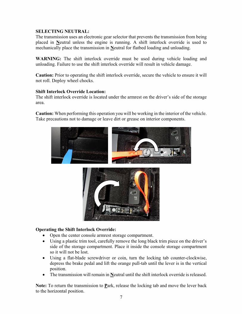
SELECTING NEUTRAL: The transmission uses an electronic gear selector that prevents the transmission from being placed in Neutral unless the engine is running. A shift interlock override is used to mechanically place the transmission in Neutral for flatbed loading and unloading. WARNING: The shift interlock override must be used during vehicle loading and unloading. Failure to use the shift interlock override will result in vehicle damage. Caution: Prior to operating the shift interlock override, secure the vehicle to ensure it will not roll. Deploy wheel chocks. Shift Interlock Override Location: The shift interlock override is located under the armrest on the driver’s side of the storage area. Caution: When performing this operation you will be working in the interior of the vehicle. Take precautions not to damage or leave dirt or grease on interior components.
Operating the Shift Interlock Override:
Open the center console armrest storage compartment. Using a plastic trim tool, carefully remove the long black trim piece on the driver’s
side of the storage compartment. Place it inside the console storage compartment so it will not be lost.
Using a flat-blade screwdriver or coin, turn the locking tab counter-clockwise, depress the brake pedal and lift the orange pull-tab until the lever is in the vertical position.
The transmission will remain in Neutral until the shift interlock override is released. Note: To return the transmission to Park, release the locking tab and move the lever back to the horizontal position.

8
Releasing the Electronic Parking Brake (EPR): The EPB applies automatically when the ignition is turned Off. To temporarily disable the parking brake:
With the ignition On-engine Off, depress the brake pedal and press down and hold the EPB switch.
Within 5 seconds, turn the ignition Off. Continue to hold down the EPB switch for 2 more seconds. The parking brake will
remain released until the next time the ignition is cycled On and Off. Caution: If the ignition is cycled On and Off, this procedure must be repeated. Releasing the Parking Brake (EPB) when the Battery is Discharged: Connect a booster pack to the jump-start pins in the engine compartment and operate the EPB switch normally. Note: If the EPB fails to release or Neutral cannot be selected, use wheel skates or wheel dolly jacks on all non-rolling wheels to load the vehicle. WARNING: Do not connect the booster pack directly to the vehicle’s battery or damage to the electrical system may occur. Securing the Vehicle for Transport: Only wheel straps should be used to secure the vehicle for transport. Damage may occur if wheel straps are not used. When the vehicle is in its loaded position on the flatbed with the bed still in the deployed position, secure the vehicle to prevent it from rolling by chocking the wheels and attaching one wheel strap to the wheel closest to you. Follow all normal loading procedures to tie down the rest of the vehicle and secure it for safe transport. Caution: Do not over tighten the wheel straps or the vehicle may be damaged. Make sure no metal portions of the strap contact the wheel. Avoid scratching any surfaces with the wheel straps.

9
Placing into Park for Transport: Once the vehicle is secured to the carrier. Reverse whatever method was used to gain Neutral and restore the vehicle to the Park position to assist in stabilizing the vehicle for transport. Car Carrier Unloading: When unloading, reverse the steps used to load the vehicle. Once unloaded, be sure to secure the vehicle by returning it to Park and applying the parking brake or wheel chocks if the parking brake will not apply. JACKING AND TIRE SERVICE: Note: This vehicle is not equipped with a factory spare tire. It is outfitted with an emergency sealant and inflator kit. The kit is located in the rear storage area. Use the following information if a road wheel must be removed/installed: Use the jacking points shown above. Place the jack in its proper location. Observe all standard jacking precautions and ensure that the vehicle is on firm, level ground and that the wheels are chocked. As the jack comes in contact with the vehicle body, ensure that it is contacting the correct and solid location on the vehicle. Note: Locking wheel nuts (if equipped) must be removed and reinstalled using a special adaptor, which can be found in either the vehicle’s tool kit or the glovebox. Be sure to return the adaptor to its original location and notify the member where you stowed it.
Jacking Points
10
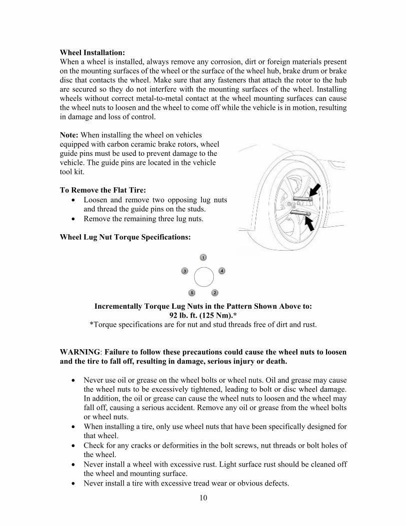
Wheel Installation: When a wheel is installed, always remove any corrosion, dirt or foreign materials present on the mounting surfaces of the wheel or the surface of the wheel hub, brake drum or brake disc that contacts the wheel. Make sure that any fasteners that attach the rotor to the hub are secured so they do not interfere with the mounting surfaces of the wheel. Installing wheels without correct metal-to-metal contact at the wheel mounting surfaces can cause the wheel nuts to loosen and the wheel to come off while the vehicle is in motion, resulting in damage and loss of control. Note: When installing the wheel on vehicles equipped with carbon ceramic brake rotors, wheel guide pins must be used to prevent damage to the vehicle. The guide pins are located in the vehicle tool kit. To Remove the Flat Tire:
Loosen and remove two opposing lug nuts and thread the guide pins on the studs.
Remove the remaining three lug nuts. Wheel Lug Nut Torque Specifications:
Incrementally Torque Lug Nuts in the Pattern Shown Above to:
92 lb. ft. (125 Nm).* *Torque specifications are for nut and stud threads free of dirt and rust.
WARNING: Failure to follow these precautions could cause the wheel nuts to loosen and the tire to fall off, resulting in damage, serious injury or death.
Never use oil or grease on the wheel bolts or wheel nuts. Oil and grease may cause the wheel nuts to be excessively tightened, leading to bolt or disc wheel damage. In addition, the oil or grease can cause the wheel nuts to loosen and the wheel may fall off, causing a serious accident. Remove any oil or grease from the wheel bolts or wheel nuts.
When installing a tire, only use wheel nuts that have been specifically designed for that wheel.
Check for any cracks or deformities in the bolt screws, nut threads or bolt holes of the wheel.
Never install a wheel with excessive rust. Light surface rust should be cleaned off the wheel and mounting surface.
Never install a tire with excessive tread wear or obvious defects.
11
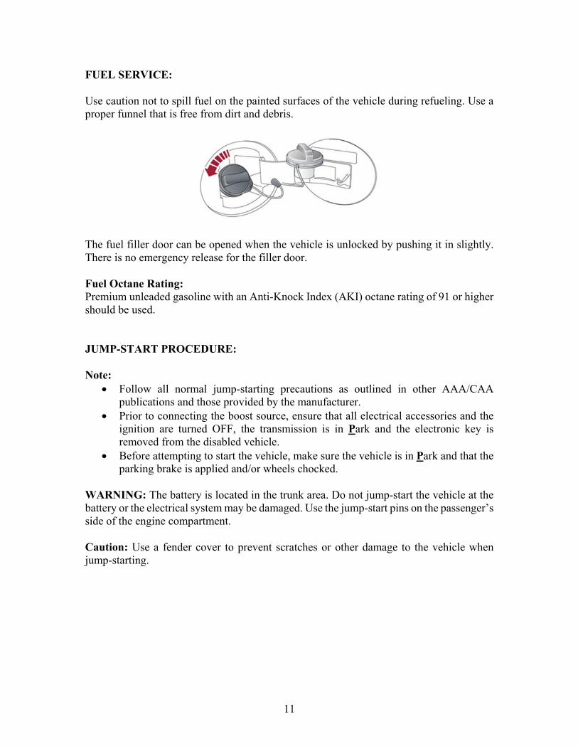
FUEL SERVICE: Use caution not to spill fuel on the painted surfaces of the vehicle during refueling. Use a proper funnel that is free from dirt and debris. The fuel filler door can be opened when the vehicle is unlocked by pushing it in slightly. There is no emergency release for the filler door. Fuel Octane Rating: Premium unleaded gasoline with an Anti-Knock Index (AKI) octane rating of 91 or higher should be used. JUMP-START PROCEDURE: Note:
Follow all normal jump-starting precautions as outlined in other AAA/CAA publications and those provided by the manufacturer.
Prior to connecting the boost source, ensure that all electrical accessories and the ignition are turned OFF, the transmission is in Park and the electronic key is removed from the disabled vehicle.
Before attempting to start the vehicle, make sure the vehicle is in Park and that the parking brake is applied and/or wheels chocked.
WARNING: The battery is located in the trunk area. Do not jump-start the vehicle at the battery or the electrical system may be damaged. Use the jump-start pins on the passenger’s side of the engine compartment. Caution: Use a fender cover to prevent scratches or other damage to the vehicle when jump-starting.
12
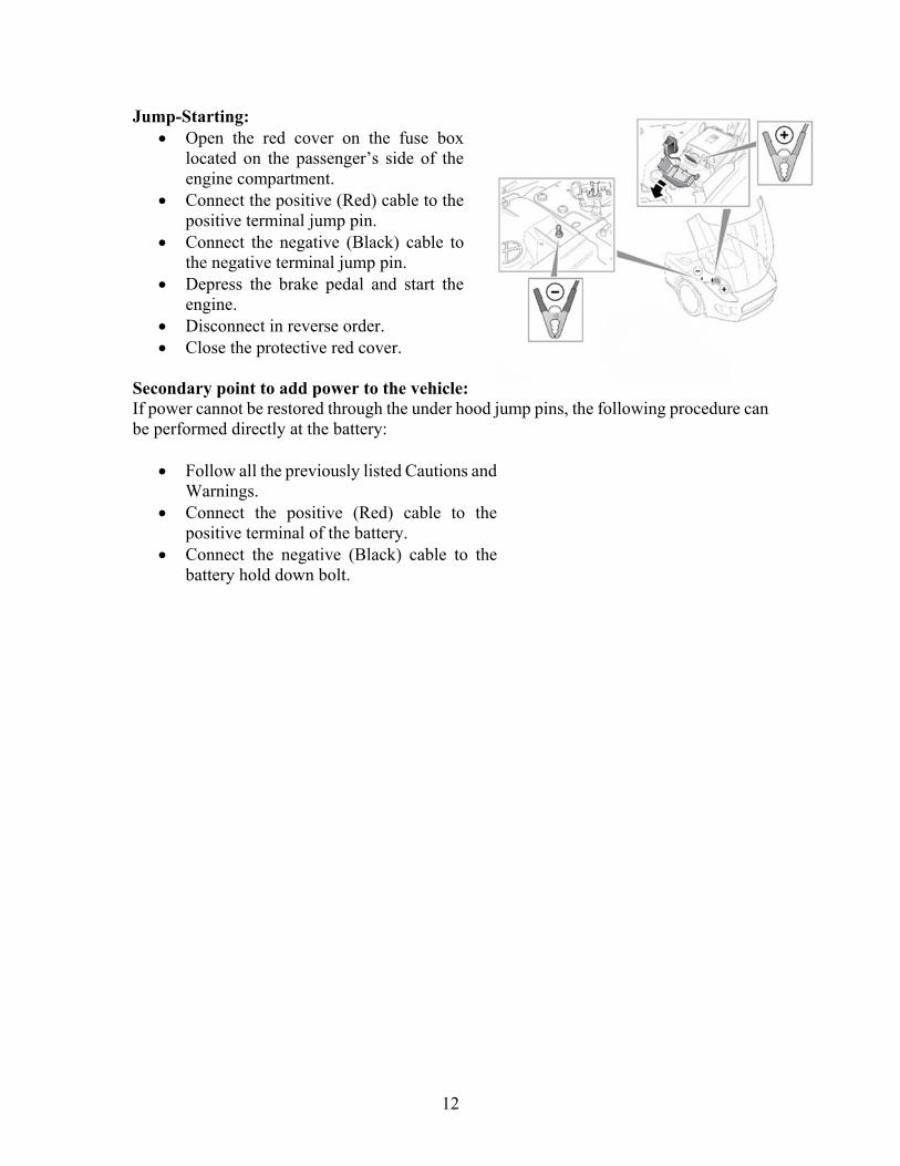
Jump-Starting: Open the red cover on the fuse box
located on the passenger’s side of the engine compartment.
Connect the positive (Red) cable to the positive terminal jump pin.
Connect the negative (Black) cable to the negative terminal jump pin.
Depress the brake pedal and start the engine.
Disconnect in reverse order. Close the protective red cover.
Secondary point to add power to the vehicle: If power cannot be restored through the under hood jump pins, the following procedure can be performed directly at the battery:
Follow all the previously listed Cautions and Warnings.
Connect the positive (Red) cable to the positive terminal of the battery.
Connect the negative (Black) cable to the battery hold down bolt.
13
ELECTRONIC KEY:
The electronic key must be inside the vehicle and detected to activate the push-button, Start/Stop system.
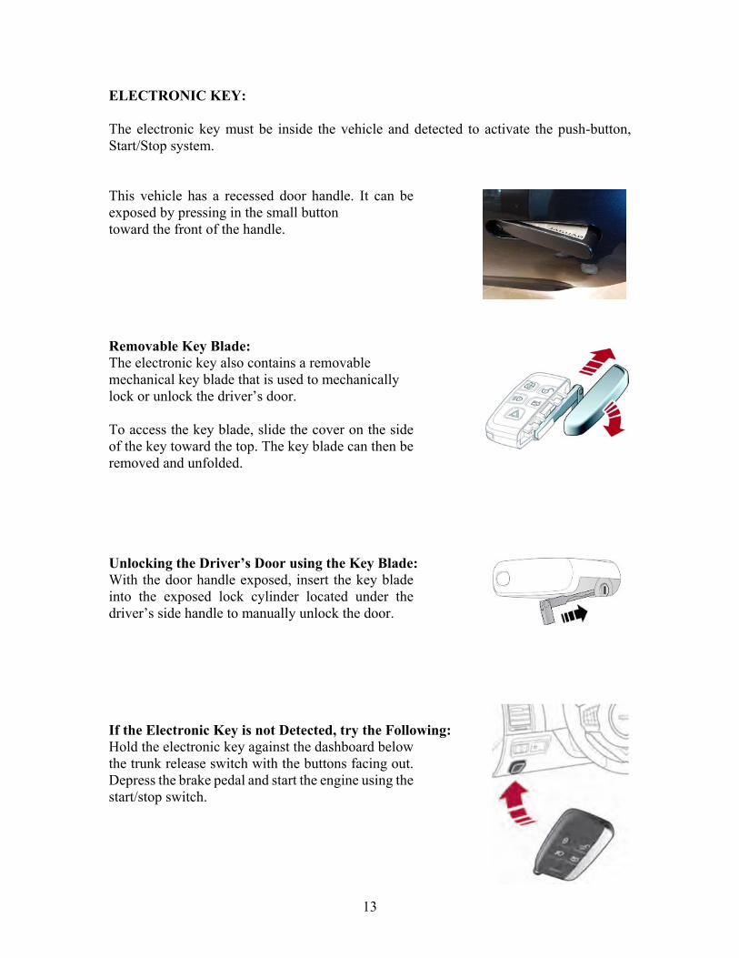
This vehicle has a recessed door handle. It can be exposed by pressing in the small button toward the front of the handle.
Removable Key Blade: The electronic key also contains a removable mechanical key blade that is used to mechanically lock or unlock the driver’s door.
To access the key blade, slide the cover on the side of the key toward the top. The key blade can then be removed and unfolded.
Unlocking the Driver’s Door using the Key Blade: With the door handle exposed, insert the key blade into the exposed lock cylinder located under the driver’s side handle to manually unlock the door.
If the Electronic Key is not Detected, try the Following: Hold the electronic key against the dashboard below the trunk release switch with the buttons facing out. Depress the brake pedal and start the engine using the start/stop switch.
14
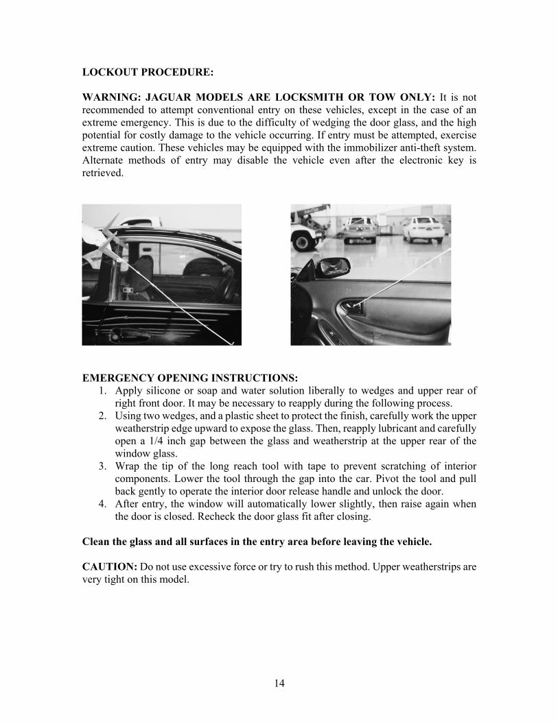
LOCKOUT PROCEDURE: WARNING: JAGUAR MODELS ARE LOCKSMITH OR TOW ONLY: It is not recommended to attempt conventional entry on these vehicles, except in the case of an extreme emergency. This is due to the difficulty of wedging the door glass, and the high potential for costly damage to the vehicle occurring. If entry must be attempted, exercise extreme caution. These vehicles may be equipped with the immobilizer anti-theft system. Alternate methods of entry may disable the vehicle even after the electronic key is retrieved.
EMERGENCY OPENING INSTRUCTIONS:
1. Apply silicone or soap and water solution liberally to wedges and upper rear of right front door. It may be necessary to reapply during the following process.
2. Using two wedges, and a plastic sheet to protect the finish, carefully work the upper weatherstrip edge upward to expose the glass. Then, reapply lubricant and carefully open a 1/4 inch gap between the glass and weatherstrip at the upper rear of the window glass.
3. Wrap the tip of the long reach tool with tape to prevent scratching of interior components. Lower the tool through the gap into the car. Pivot the tool and pull back gently to operate the interior door release handle and unlock the door.
4. After entry, the window will automatically lower slightly, then raise again when the door is closed. Recheck the door glass fit after closing.
Clean the glass and all surfaces in the entry area before leaving the vehicle. CAUTION: Do not use excessive force or try to rush this method. Upper weatherstrips are very tight on this model.