Embed Size (px)
Citation preview
Robotic Platform 1kg2008 (Fall)Detailed Design Review Document
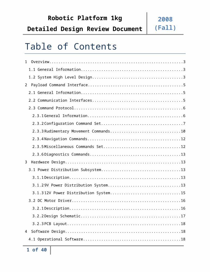
Table of Contents1 Overview...............................................................................................................................................3
1.1 General Information.......................................................................................................................3
1.2 System High Level Design...............................................................................................................3
2 Payload Command Interface.................................................................................................................5
2.1 General Information.......................................................................................................................5
2.2 Communication Interfaces.............................................................................................................5
2.3 Command Protocol........................................................................................................................6
2.3.1 General Information................................................................................................................6
2.3.2 Configuration Command Set...................................................................................................7
2.3.3 Rudimentary Movement Commands....................................................................................10
2.3.4 Navigation Commands..........................................................................................................12
2.3.5 Miscellaneous Commands Set...............................................................................................12
2.3.6 Diagnostics Commands.........................................................................................................13
3 Hardware Design.................................................................................................................................13
3.1 Power Distribution Subsystem.....................................................................................................13
3.1.1 Description............................................................................................................................13
3.1.2 9V Power Distribution System...............................................................................................13
3.1.3 12V Power Distribution System.............................................................................................15
3.2 DC Motor Driver...........................................................................................................................16
3.2.1 Description............................................................................................................................16
3.2.2 Design Schematic..................................................................................................................17
3.2.3 PCB Layout............................................................................................................................18
4 Software Design..................................................................................................................................18
4.1 Operational Software...................................................................................................................18
4.1.1 Software High Level Design...................................................................................................18
4.2 Application Programmers Interface.............................................................................................20
4.2.1 TWI (I2C)................................................................................................................................21
1 of 33
Robotic Platform 1kg2008 (Fall)Detailed Design Review Document
5 Programmable Interface Controller (PIC) Subsystem..........................................................................26
5.1 PIC Overview................................................................................................................................26
5.2 PWM Generation using Capture Compare Registers...................................................................26
5.3 Encoder Feedback........................................................................................................................27
5.4 Communication via the I2C Bus....................................................................................................28
5.5 In-Circuit Serial Programming (ICSP)............................................................................................30
6 Feasibility............................................................................................................................................30
6.1 Standing Issues.............................................................................................................................30
6.2 Issue Resolution Plan...................................................................................................................30
7 Acronyms............................................................................................................................................31
8 Document References.........................................................................................................................31
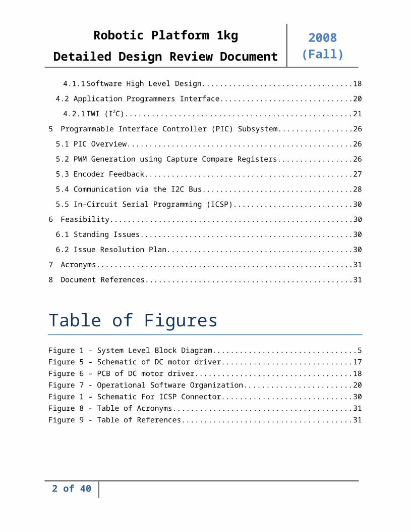
Table of FiguresFigure 1 - System Level Block Diagram........................................................................................................5Figure 5 – Schematic of DC motor driver...................................................................................................17Figure 6 – PCB of DC motor driver.............................................................................................................18Figure 7 - Operational Software Organization...........................................................................................20Figure 1 – Schematic For ICSP Connector..................................................................................................30Figure 8 - Table of Acronyms.....................................................................................................................31Figure 9 - Table of References...................................................................................................................31
2 of 33
Robotic Platform 1kg2008 (Fall)Detailed Design Review Document
1 Overview
1.1 General InformationThe Robotic Platform for 1kg Payloads (RP1) is a robotic assembly and physical platform built for the purpose of expediting construction of robotics of a much higher complexity. Quite frequently rudimentary navigation and obstacle avoidance logic consumes a large portion of time when building any robotic device. This platform is intended for applications in which a robotic device needs navigation control but the builder does not want to focus a lot of time or money into designing the components which manipulate motion.
The RP1 system consists of two core assemblies: the RP1 Control System and the RP1 Mechanical Motor Module and chassis. The control system will interface with a payload which will have full control over the platform itself. This will allow the payload to control the navigation of the platform. The payload in this instance would be any robotic device which will build off of the RP1 platform as a basis of motion.
The platform does not rely solely on the payload to command navigation. The RP1 control system also comes equipped with a wireless communications device which will allow a user at any PC machine equipped with the Graphical User Interface (GUI) software and appropriate wireless communication hardware to control navigation of the robotic platform. In this scenario, the payload may rest idle and perform its own, separate tasks or it may poll the platform for encoder data, power data, or any peripheral sensor data for which the system may come equipped.
1.2 System High Level DesignThe System High Level Design is the technical layout and design of the RP1 control system. The system is broken down into a number of subsystems which are each designed, implemented, and tested individually and tested during system integration.
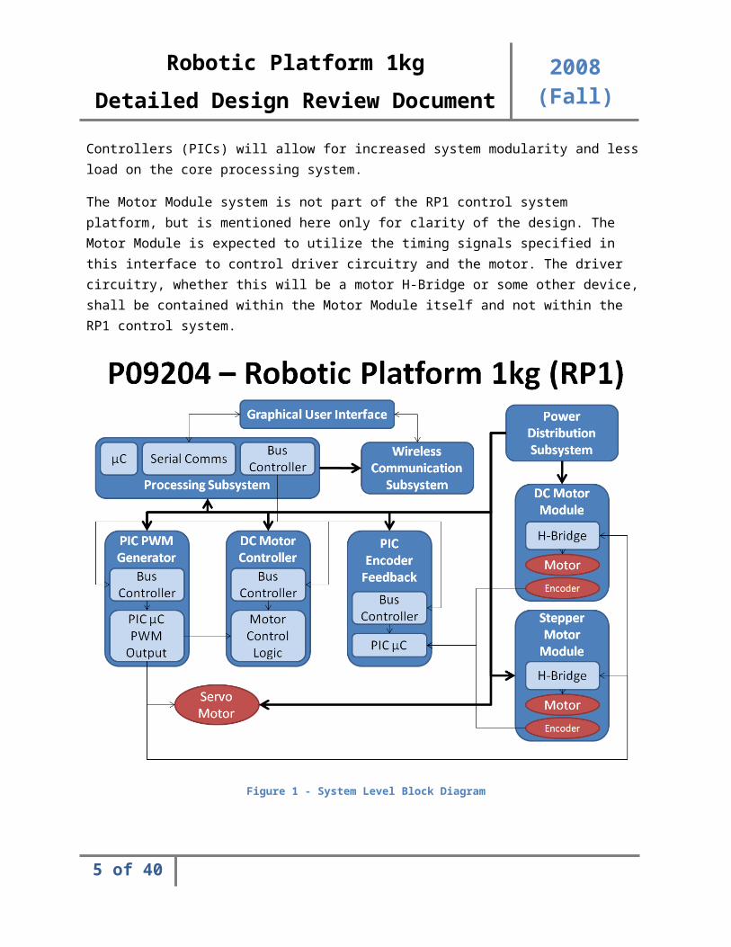
There are a total of seven subsystems, the Graphical User Interface, the Wireless Communications subsystem, the Power Distribution subsystem, the Processing subsystem, the Motor Module Controller subsystem, and lastly the Motor Module subsystem. A block diagram of these subsystems and their interconnections is displayed in Figure 1.
The Graphical User Interface (GUI) is a software application written in JAVA and is thusly cross platform compatible. Any operating system running the JAVA JRE (Java Runtime Environment) will be able to run the GUI client software.
The Wireless Communications subsystem is a subsystem dedicated to maintaining wireless control over the robotic platform. The details of the communications protocol shared by both wireless and wired communications channels are described in section 2.
3 of 33
Robotic Platform 1kg2008 (Fall)Detailed Design Review Document
The Processing subsystem is the computational heart of the robotic platform. This subsystem contains the processing core which computes all commands issued through the communication channel into motor controls and sensor feedback to the user. The details of this subsystem are not relevant within the scope of the ICD, for more information please reference the Customer Needs, Design Specifications, and any design documentation which may pertain to the Processing subsystem.
The Motor Module Controller subsystem and subsequent Motor Module subsystem are the logic and device systems for actuating a motor. The Motor Module Controller subsystem contains logic to actuate a motor, but does not contain the motor or driver circuitry itself. The controller subsystem simply generates the timing and control signals which are then fed into the Motor Module subsystem. There are a variety of Motor Module controllers for the various supported motors. DC and Stepper motors required extra controller and timing circuitry to operate, while Servos require only Pulse Width Modulation (PWM) input. DC and Stepper motors require PWM inputs as well. Moving PWM generation responsibility off chip onto Programmable Interface Controllers (PICs) will allow for increased system modularity and less load on the core processing system.
The Motor Module system is not part of the RP1 control system platform, but is mentioned here only for clarity of the design. The Motor Module is expected to utilize the timing signals specified in this interface to control driver circuitry and the motor. The driver circuitry, whether this will be a motor H-Bridge or some other device, shall be contained within the Motor Module itself and not within the RP1 control system.
4 of 33
Robotic Platform 1kg2008 (Fall)Detailed Design Review Document
Figure 1 - System Level Block Diagram
2 Payload Command Interface
2.1 General InformationThe payload and/or any PC may utilize one of the numerous communication interfaces the RP1 system provides to control the platform and its peripheral devices. The software which resides on the control system, the Operational Software (OpSoft), is a Real-Time Operating System (RTOS) designed to provide the user with a multitude of commands to control every device internal to the platform and those devices attached externally to the platform.
2.2 Communication InterfacesThe RP1 control system supports multiple communication channels for which the payload or user may communicate with the system. There are two interfaces which may be used: the RS-232 wired or Crossbow Wireless.
5 of 33
Robotic Platform 1kg2008 (Fall)Detailed Design Review Document
When the payload uses the RS-232 interface the nomenclature for this interface is “wired communication”. When the user uses a terminal emulator or the GUI software on a PC the nomenclature for this interface is “tethered communication”. When a payload or a PC computer uses the Crossbow wireless interface the nomenclature for this channel is “wireless communication”.
There is no multiple access mitigation implemented for both the RS-232 and Crossbow Wireless communication channels being active simultaneously. Both communication channels may send commands to the platform simultaneously but will be processed sequentially. For example, if a movefwd command is sent over RS-232 and is processed and then a moverev command is sent over wireless, the platform will process both commands in order as if any one channel had sent both of the commands in order.
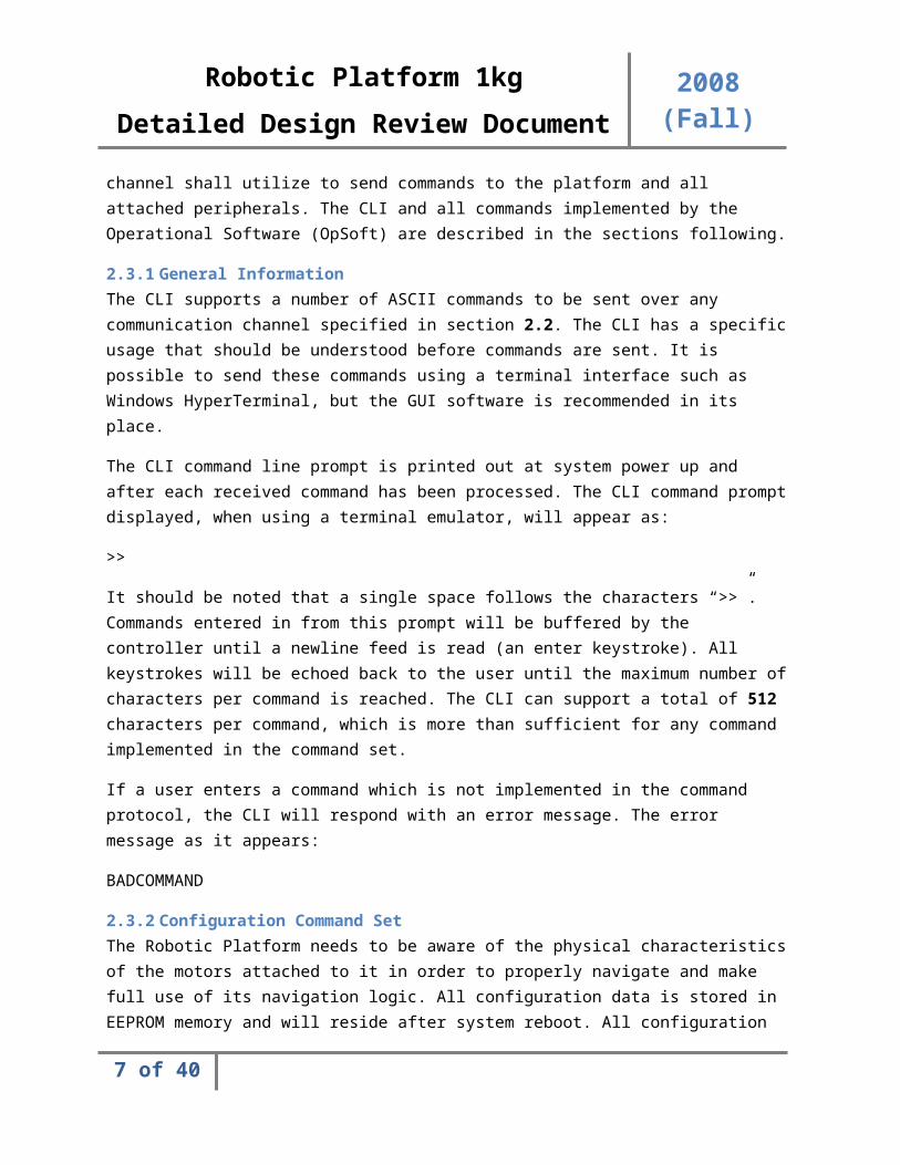
2.3 Command ProtocolThe RP1 Control System will provide a rudimentary Command Line Interface (CLI) for which the user or payload using any communication channel shall utilize to send commands to the platform and all attached peripherals. The CLI and all commands implemented by the Operational Software (OpSoft) are described in the sections following.
2.3.1 General InformationThe CLI supports a number of ASCII commands to be sent over any communication channel specified in section 2.2. The CLI has a specific usage that should be understood before commands are sent. It is possible to send these commands using a terminal interface such as Windows HyperTerminal, but the GUI software is recommended in its place.
The CLI command line prompt is printed out at system power up and after each received command has been processed. The CLI command prompt displayed, when using a terminal emulator, will appear as:
>>
It should be noted that a single space follows the characters “>>”. Commands entered in from this prompt will be buffered by the controller until a newline feed is read (an enter keystroke). All keystrokes will be echoed back to the user until the maximum number of characters per command is reached. The CLI can support a total of 512 characters per command, which is more than sufficient for any command implemented in the command set.
If a user enters a command which is not implemented in the command protocol, the CLI will respond with an error message. The error message as it appears:
BADCOMMAND
2.3.2 Configuration Command SetThe Robotic Platform needs to be aware of the physical characteristics of the motors attached to it in order to properly navigate and make full use of its navigation logic. All configuration data is stored in
6 of 33
Robotic Platform 1kg2008 (Fall)Detailed Design Review Document
EEPROM memory and will reside after system reboot. All configuration data is made available to the robot immediately after configuration without the need to reboot the robot.
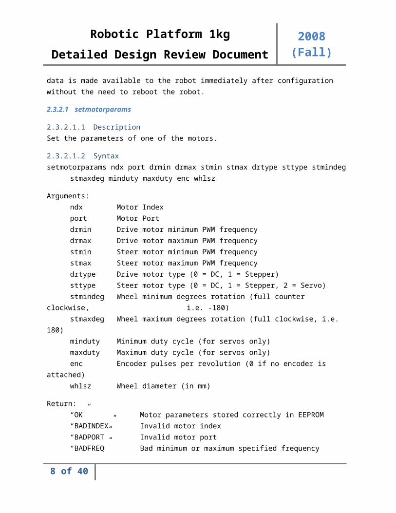
2.3.2.1 setmotorparams
2.3.2.1.1 DescriptionSet the parameters of one of the motors.
2.3.2.1.2 Syntaxsetmotorparams ndx port drmin drmax stmin stmax drtype sttype stmindeg
stmaxdeg minduty maxduty enc whlsz
Arguments:ndx Motor Indexport Motor Portdrmin Drive motor minimum PWM frequencydrmax Drive motor maximum PWM frequencystmin Steer motor minimum PWM frequencystmax Steer motor maximum PWM frequencydrtype Drive motor type (0 = DC, 1 = Stepper)sttype Steer motor type (0 = DC, 1 = Stepper, 2 = Servo)stmindeg Wheel minimum degrees rotation (full counter
clockwise, i.e. -180)stmaxdeg Wheel maximum degrees rotation (full clockwise, i.e.
180)minduty Minimum duty cycle (for servos only)maxduty Maximum duty cycle (for servos only)enc Encoder pulses per revolution (0 if no encoder is
attached)whlsz Wheel diameter (in mm)
Return:“OK” Motor parameters stored correctly in EEPROM“BADINDEX” Invalid motor index“BADPORT” Invalid motor port“BADFREQ” Bad minimum or maximum specified frequency“BADTYPE” Bad motor type“BADDEGREES” Invalid degrees specification (-180 to 180)“BADDUTY” Invalid duty cycle specified“BADENC” Bad encoder pulses per revolution“BADWHEELSIZE” Bad wheel diameter“SYSFAIL” Unknown system failure
7 of 33
Robotic Platform 1kg2008 (Fall)Detailed Design Review Document
2.3.2.2 getmotorparams
2.3.2.2.1 DescriptionGet and return all parameters for the motor, space delimited.
2.3.2.2.2 Syntaxgetmotorparams ndx
Arguments:ndx Motor Index
Return:“port drmin drmax stmin stmax drtype sttype stmindeg stmaxdegminduty maxduty enc whlsz”
Returns a space delimited list of parameters associated with the motor, see setmotorparams for details on each parameter
“SYSFAIL” Unknown system failure
2.3.2.3 deletemotor
2.3.2.3.1 DescriptionRemove a motor module from the system.
2.3.2.3.2 Syntaxdeletemotor ndx
Arguments:ndx Motor Index
Return:“OK” Motor module configuration deleted, motor
detached“SYSFAIL” Unknown system failure
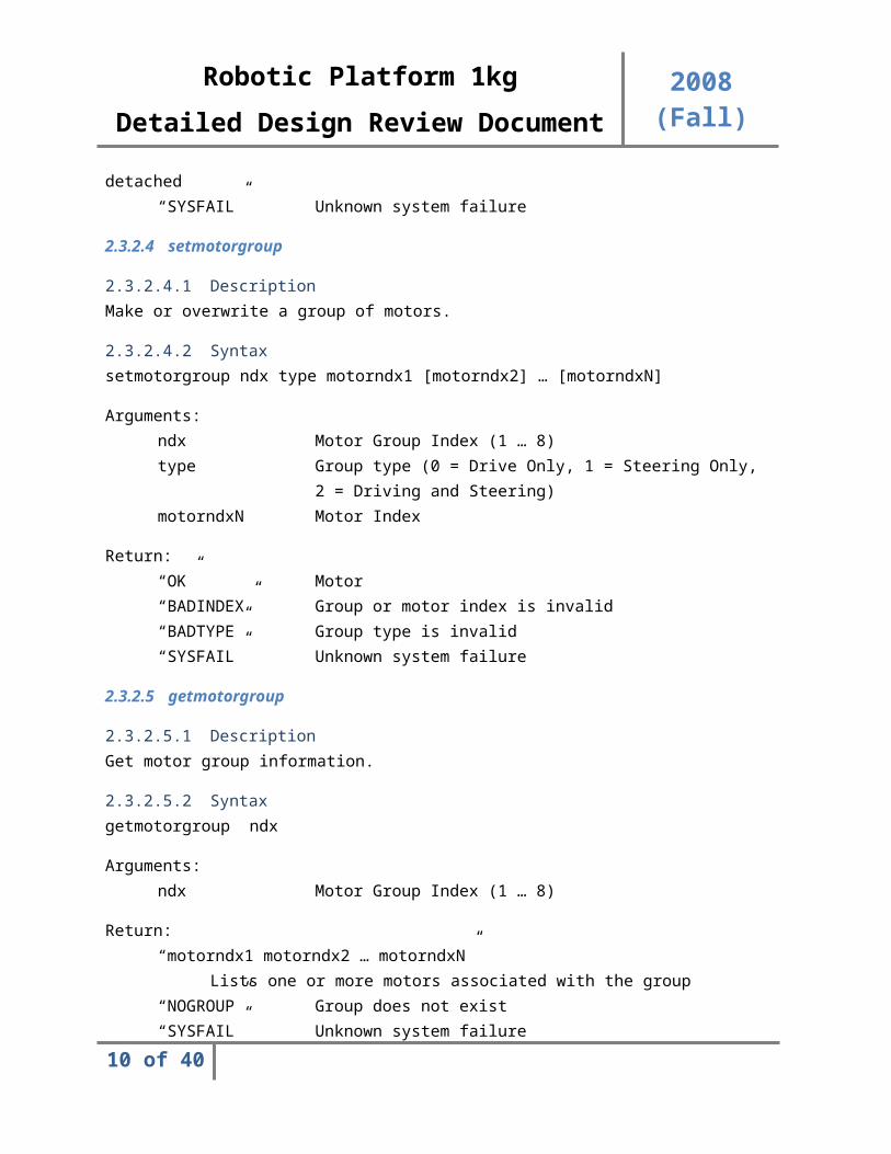
2.3.2.4 setmotorgroup
2.3.2.4.1 DescriptionMake or overwrite a group of motors.
2.3.2.4.2 Syntaxsetmotorgroup ndx type motorndx1 [motorndx2] … [motorndxN]
Arguments:ndx Motor Group Index (1 … 8)type Group type (0 = Drive Only, 1 = Steering Only,
8 of 33

Robotic Platform 1kg2008 (Fall)Detailed Design Review Document
2 = Driving and Steering)motorndxN Motor Index
Return:“OK” Motor“BADINDEX” Group or motor index is invalid“BADTYPE” Group type is invalid“SYSFAIL” Unknown system failure
2.3.2.5 getmotorgroup
2.3.2.5.1 DescriptionGet motor group information.
2.3.2.5.2 Syntaxgetmotorgroup ndx
Arguments:ndx Motor Group Index (1 … 8)
Return:“motorndx1 motorndx2 … motorndxN”
Lists one or more motors associated with the group“NOGROUP” Group does not exist“SYSFAIL” Unknown system failure
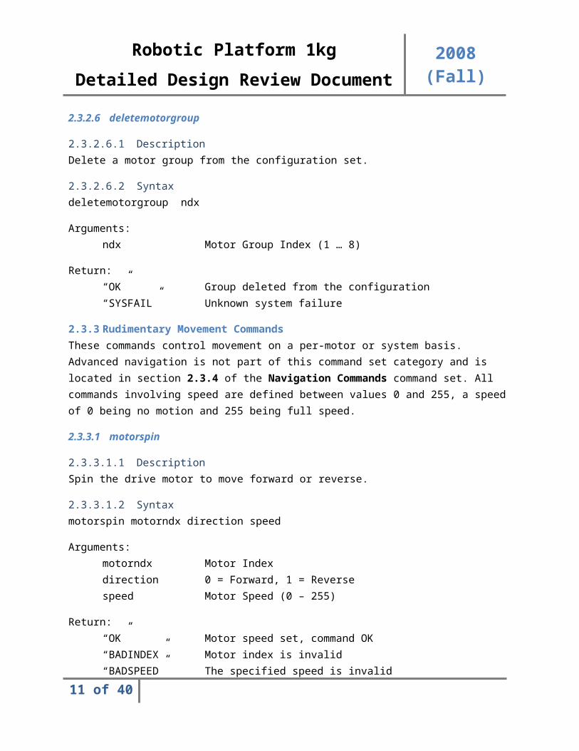
2.3.2.6 deletemotorgroup
2.3.2.6.1 DescriptionDelete a motor group from the configuration set.
2.3.2.6.2 Syntaxdeletemotorgroup ndx
Arguments:ndx Motor Group Index (1 … 8)
Return:“OK” Group deleted from the configuration“SYSFAIL” Unknown system failure
2.3.3 Rudimentary Movement CommandsThese commands control movement on a per-motor or system basis. Advanced navigation is not part of this command set category and is located in section 2.3.4 of the Navigation Commands command set.
9 of 33
Robotic Platform 1kg2008 (Fall)Detailed Design Review Document
All commands involving speed are defined between values 0 and 255, a speed of 0 being no motion and 255 being full speed.
2.3.3.1 motorspin
2.3.3.1.1 DescriptionSpin the drive motor to move forward or reverse.
2.3.3.1.2 Syntaxmotorspin motorndx direction speed
Arguments:motorndx Motor Indexdirection 0 = Forward, 1 = Reversespeed Motor Speed (0 – 255)
Return:“OK” Motor speed set, command OK“BADINDEX” Motor index is invalid“BADSPEED” The specified speed is invalid“BADDIRECTION” Invalid direction setting (neither 0 nor 1)“SYSFAIL” Unknown system failure
2.3.3.2 motorturn
2.3.3.2.1 DescriptionActuate steer motors to rotate the driver motor of a motor module.
2.3.3.2.2 Syntaxmotorturn motorndx degrees
Arguments:motorndx Motor Indexdegrees Number of degrees to rotate (-180 to 180), a
degreesinput of 0 re-centers the wheel
Return:“OK” Steering motor turning OK“BADINDEX” Invalid motor index“BADDEGREES” Number of degrees is invalid“SYSFAIL” Unknown system failure
10 of 33
Robotic Platform 1kg2008 (Fall)Detailed Design Review Document
2.3.3.3 getmotorstatus
2.3.3.3.1 DescriptionReturn the current speed and rotation status of a motor module.
2.3.3.3.2 Syntaxgetmotorstatus motorndx
Arguments:motorndx Motor Index
Return:“speed degrees” Returns the current speed setting and the
currentdegrees of rotation
“BADINDEX” Invalid motor index“SYSFAIL” Unknown system failure
2.3.3.4 movegroup
2.3.3.4.1 DescriptionSet drive motor speed and direction and steering motor degrees of rotation of an entire motor group. This essentially performs a motorspin and motorturn command on every motor specified in a defined motor group.
2.3.3.4.2 Syntaxmovegroup groupndx direction speed degrees
Arguments:groupndx Motor Group Index (1 … 8)direction 0 = Forward, 1 = Reversespeed Motor Speed (0 – 255)degrees Number of degrees to rotate (-180 to 180), a
degreesinput of 0 re-centers the wheel
Return:“OK” Group of motors configured to move and turn“BADINDEX” Invalid motor group index (1 … 8)“BADSPEED” The specified speed is invalid“BADDIRECTION” Invalid direction setting (neither 0 nor 1)“BADDEGREES” Number of degrees is invalid“SYSFAIL” Unknown system failure
11 of 33
Robotic Platform 1kg2008 (Fall)Detailed Design Review Document
2.3.4 Navigation CommandsExpert controlled navigation logic utilizes Rudimentary Navigation controls to perform more intelligent navigation procedures. System must be fully and correctly calibrated before using these commands to ensure accurate navigation. Certain commands may require the attachment of specific sensors to function and will not behave according to specification if these sensors are not attached.
2.3.5 Miscellaneous Commands SetAny command that does not fit into the aforementioned command sets is described below.
2.3.5.1 readpwr
2.3.5.1.1 DescriptionRead battery life. The returned value will be an integer ranging from 0 to 100 representing the battery life percentage.
2.3.5.1.2 Syntaxreadpwr
Return:“0” – “100” Percent battery life remaining“SYSFAIL” Unknown system failure
2.3.5.2 twiread
2.3.5.2.1 DescriptionRead and report data from an external TWI device. Limit data read to 128 bytes per read. If a reserved address is specified, twiread will reject the command. If a length above 128 bytes is specified, the request will be rejected.
2.3.5.2.2 Syntaxtwiread addr len
Arguments:addr Address of external TWI device (in Hexadecimal)len Length of data to read (in decimal)
Return:“00 01 …” Returns len number of bytes in hexadecimal,
space delimited“BADADDR” Invalid address specified“BADLENGTH” Invalid length specified“NODEVICE” No device with that address exists on bus“BUSFAIL” TWI bus error encountered“SYSFAIL” Unknown system failure
12 of 33

Robotic Platform 1kg2008 (Fall)Detailed Design Review Document
2.3.5.3 twiwrite
2.3.5.3.1 DescriptionWrite data to an external TWI device. Limit data length to 128 bytes per write. If a reserved address is specified, twiwrite will reject the command. The command will ignore any data byte beyond the 128th byte.
2.3.5.3.2 Syntaxtwiwrite addr data1 data2 … dataN
Arguments:addr Address of external TWI device (in Hexadecimal)data1 … dataN Bytes of data in hexadecimal, space delimited
Return:“OK” TWI write successful, command OK“BADADDR” Invalid address specified“NODEVICE” No device with that address exists on bus“BUSFAIL” TWI bus error encountered“SYSFAIL” Unknown system failure
2.3.6 Diagnostics CommandsThis set of commands is for developer use only and is not utilized by the GUI client software in any fashion. These commands aid the developer in debugging hardware or software problems and are included here for convenience.
3 Hardware Design
3.1 Power Distribution Subsystem
3.1.1 DescriptionPower distribution is a very important aspect of the design. The design utilizes two separate batteries to power two distinct power distribution boards as described below.
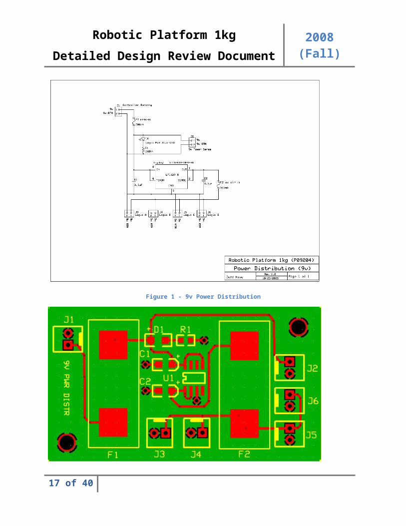
3.1.2 9V Power Distribution SystemA 9V battery and distribution system is used to supply power to the microcontroller and other logic subsystems. The current is limited to less than 700mA by a fuse at the input. A status LED is used to indicate the operation of the system and a power sense output is used to supply a reading of the voltage input. The 9V input is fed through a 5V regulator and subsequently fed to four identical 5V outputs. Capacitors are utilized at both the input and output of the regulator to improve stability and prevent rapid changes in current. This current is again limited through the use of a fuse to under 500mA. All fuses are mounted with fuse clips to provide ease of access and replacement as necessary.
13 of 33
Robotic Platform 1kg2008 (Fall)Detailed Design Review Document
Figure 1 - 9v Power Distribution
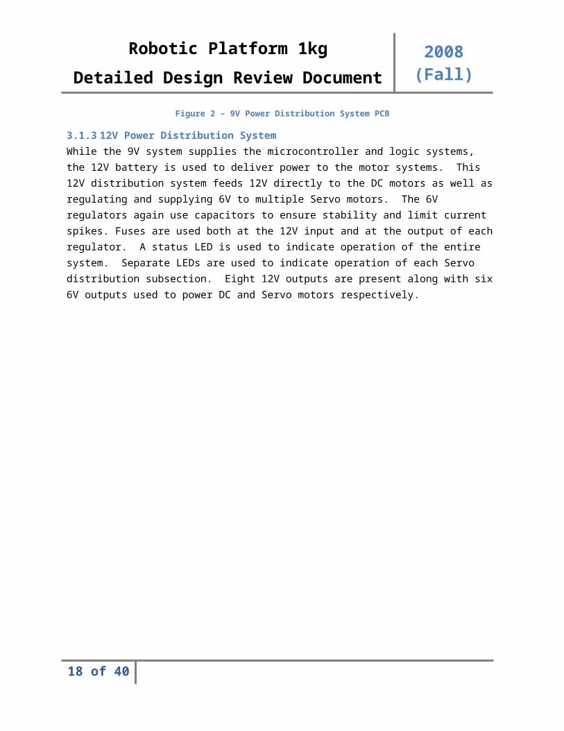
Figure 2 – 9V Power Distribution System PCB
14 of 33
Robotic Platform 1kg2008 (Fall)Detailed Design Review Document
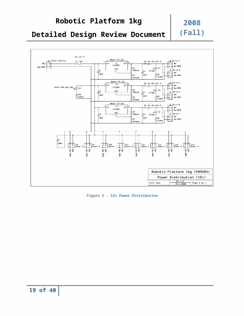
3.1.3 12V Power Distribution SystemWhile the 9V system supplies the microcontroller and logic systems, the 12V battery is used to deliver power to the motor systems. This 12V distribution system feeds 12V directly to the DC motors as well as regulating and supplying 6V to multiple Servo motors. The 6V regulators again use capacitors to ensure stability and limit current spikes. Fuses are used both at the 12V input and at the output of each regulator. A status LED is used to indicate operation of the entire system. Separate LEDs are used to indicate operation of each Servo distribution subsection. Eight 12V outputs are present along with six 6V outputs used to power DC and Servo motors respectively.
Figure 3 - 12v Power Distribution
15 of 33
Robotic Platform 1kg2008 (Fall)Detailed Design Review Document
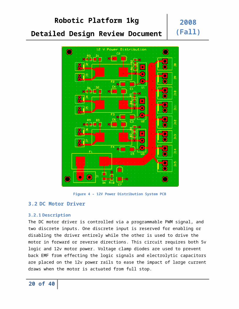
Figure 4 – 12V Power Distribution System PCB
3.2 DC Motor Driver
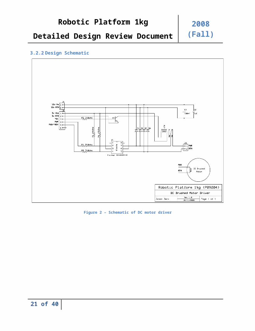
3.2.1 DescriptionThe DC motor driver is controlled via a programmable PWM signal, and two discrete inputs. One discrete input is reserved for enabling or disabling the driver entirely while the other is used to drive the motor in forward or reverse directions. This circuit requires both 5v logic and 12v motor power. Voltage clamp diodes are used to prevent back EMF from effecting the logic signals and electrolytic capacitors are placed on the 12v power rails to ease the impact of large current draws when the motor is actuated from full stop.
16 of 33
Robotic Platform 1kg2008 (Fall)Detailed Design Review Document
3.2.2 Design Schematic
Figure 2 – Schematic of DC motor driver
17 of 33
Robotic Platform 1kg2008 (Fall)Detailed Design Review Document
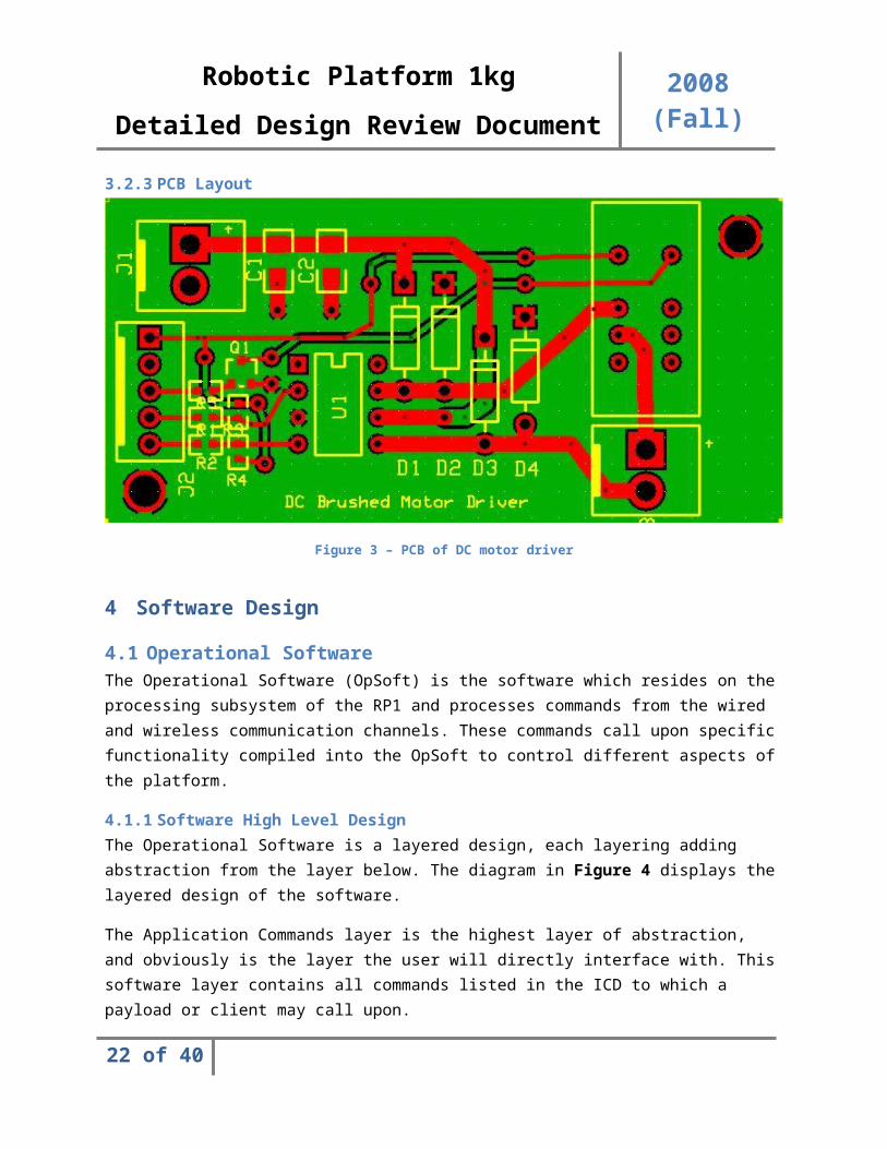
3.2.3 PCB Layout
Figure 3 – PCB of DC motor driver
4 Software Design
4.1 Operational SoftwareThe Operational Software (OpSoft) is the software which resides on the processing subsystem of the RP1 and processes commands from the wired and wireless communication channels. These commands call upon specific functionality compiled into the OpSoft to control different aspects of the platform.
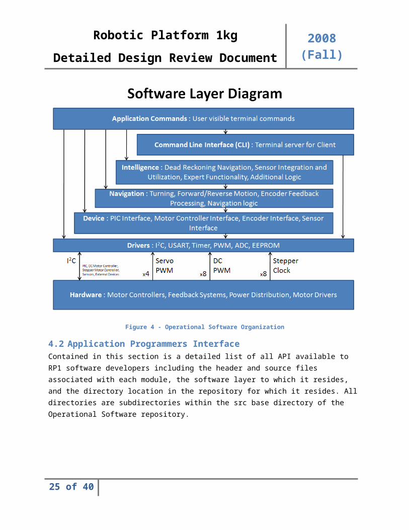
4.1.1 Software High Level DesignThe Operational Software is a layered design, each layering adding abstraction from the layer below. The diagram in Figure 4 displays the layered design of the software.
The Application Commands layer is the highest layer of abstraction, and obviously is the layer the user will directly interface with. This software layer contains all commands listed in the ICD to which a payload or client may call upon.
The Command Line Interface (CLI) layer is an integral layer which contains all core logic for allowing swift implementation of new application commands. This layer need not be edited when adding new commands but must be thoroughly understood in order to develop new commands appropriately. This layer handles multiple access (communication with both wired and wireless channels on two RS-232 ports), and does so seamlessly without concerning the Application Commands layer above.
The Intelligence layer contains all advanced logic for “smart” navigation and advanced algorithms for processing and utilizing sensor feedback. This layer should contain all functionality which is more
18 of 33
Robotic Platform 1kg
2008 (Fall)Detailed Design Review Document
advanced than any rudimentary navigation control, such as accurate robotic positioning or extraneous sensor integration.
The Navigation layer contains all functionality to convert speed input, motor indexing, forward/reverse input, and any desired rudimentary motion commands into the appropriate signals to registered devices. This layer contains all the necessary logic to translate commands such as “move motor N forward at a speed of X” or “turn wheel N a number of degrees X clockwise” into commands to specific devices, abstract speed calculations, and incorporation of closed loop feedback values when utilizing encoder feedback signals.
The Device layer is a single layer of abstraction over the driver layer, but is very similar in behavior. The Device layer contains any I2C addresses, timer configuration parameters, knowledge of motor controller signals, and any device specific configuration or parameters and can convert abstract commands to control a device into a procedure of actions which are performed on devices attached to the system. Such devices may include but are not limited to motor controllers, I2C devices (PIC controllers over serial interface), Encoder Feedback circuitry, and any peripheral device attached to the microcontroller.The device layer also contains core operating system code including linked lists structures, threads control, semaphore logic, and additional operating system tools. These tools are placed here because they reside at a higher level of intelligence above the drivers but belong strictly below the navigation layers. Instead of making another layer separate to devices but residing in the same level, it was decided to put this responsibility within the device layer, despite these modules not being devices.
The Driver layer is the layer closest to the hardware itself and contains all code which controls microcontroller hardware functionality. Universal Synchronous/Asynchronous Receiver/Transmitter (USART) Input/Output (I/O) and configuration, timer and PWM configuration and operation control, EEPROM configuration and read/write functionality, I2C packet I/O, Analog to Digital Converter (ADC) functionality, and other such on-chip device functionality exists here. All interrupt management is handled strictly in this layer only and shall not be utilized in any layer of higher abstraction.
19 of 33
Robotic Platform 1kg
2008 (Fall)Detailed Design Review Document
Figure 4 - Operational Software Organization
4.2 Application Programmers InterfaceContained in this section is a detailed list of all API available to RP1 software developers including the header and source files associated with each module, the software layer to which it resides, and the directory location in the repository for which it resides. All directories are subdirectories within the src base directory of the Operational Software repository.
20 of 33
Robotic Platform 1kg
2008 (Fall)Detailed Design Review Document
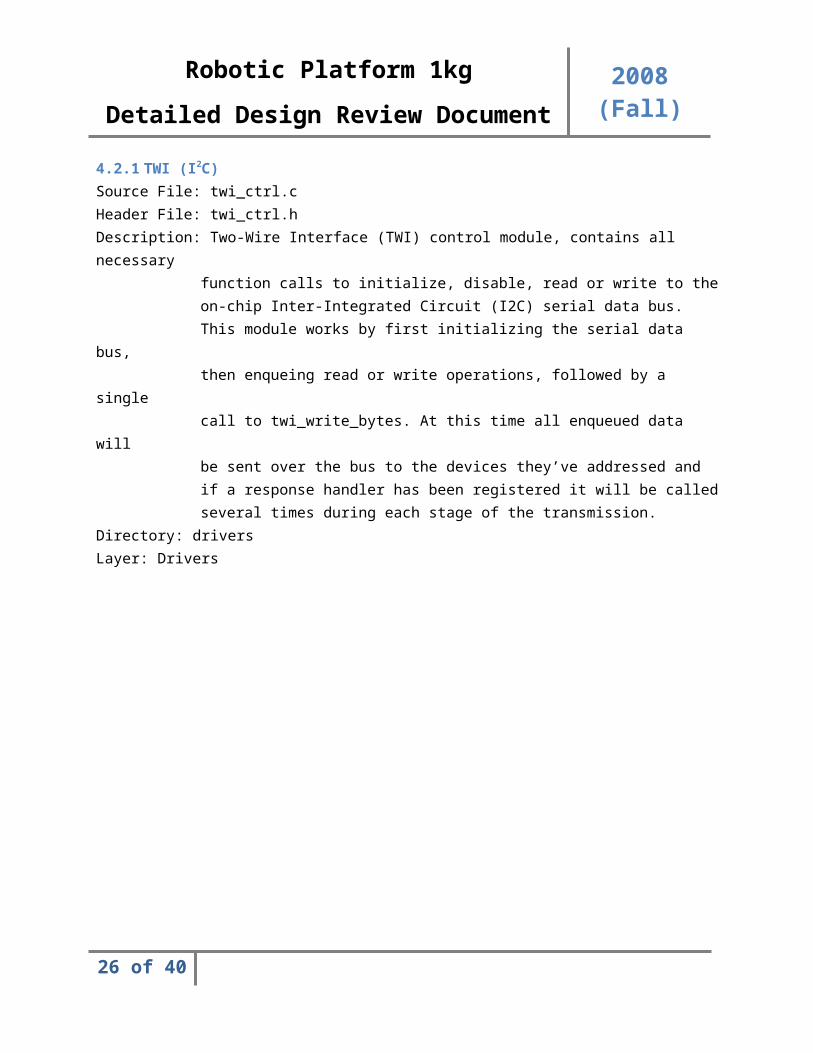
4.2.1 TWI (I2C)Source File: twi_ctrl.cHeader File: twi_ctrl.hDescription: Two-Wire Interface (TWI) control module, contains all necessary
function calls to initialize, disable, read or write to the
on-chip Inter-Integrated Circuit (I2C) serial data bus. This module works by first initializing the serial data
bus, then enqueing read or write operations, followed by a
single call to twi_write_bytes. At this time all enqueued data
will be sent over the bus to the devices they’ve addressed and if a response handler has been registered it will be
called several times during each stage of the transmission.
Directory: driversLayer: Drivers
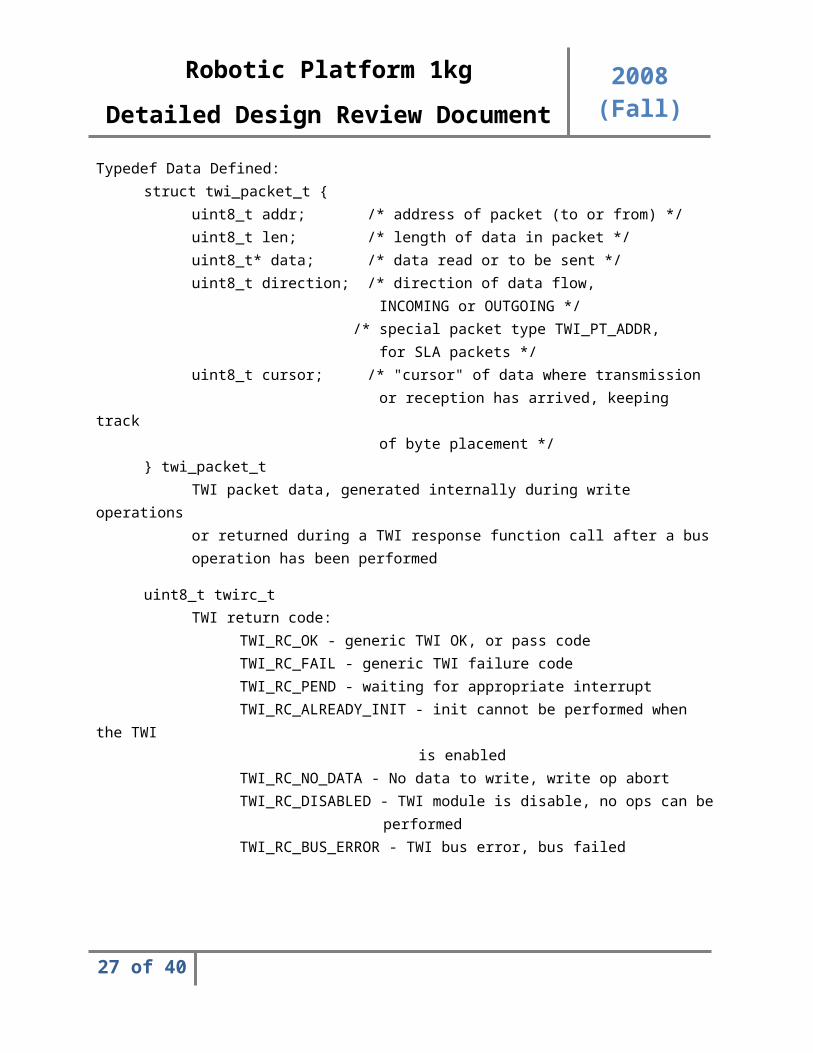
Typedef Data Defined:struct twi_packet_t {
uint8_t addr; /* address of packet (to or from) */uint8_t len; /* length of data in packet */uint8_t* data; /* data read or to be sent */uint8_t direction; /* direction of data flow,
INCOMING or OUTGOING */ /* special packet type TWI_PT_ADDR, for SLA packets */
uint8_t cursor; /* "cursor" of data where transmission or reception has arrived, keeping
track of byte placement */
} twi_packet_tTWI packet data, generated internally during write
operationsor returned during a TWI response function call after a busoperation has been performed
21 of 33
Robotic Platform 1kg
2008 (Fall)Detailed Design Review Document
uint8_t twirc_tTWI return code:
TWI_RC_OK - generic TWI OK, or pass codeTWI_RC_FAIL - generic TWI failure codeTWI_RC_PEND - waiting for appropriate interruptTWI_RC_ALREADY_INIT - init cannot be performed when
the TWI is enabled
TWI_RC_NO_DATA - No data to write, write op abortTWI_RC_DISABLED - TWI module is disable, no ops can be
performedTWI_RC_BUS_ERROR - TWI bus error, bus failed
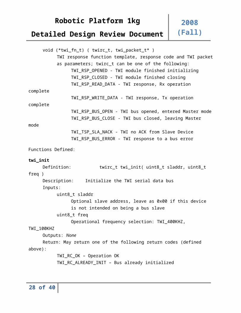
void (*twi_fn_t) ( twirc_t, twi_packet_t* )TWI response function template, response code and TWI
packetas parameters; twirc_t can be one of the following:
TWI_RSP_OPENED - TWI module finished initializingTWI_RSP_CLOSED - TWI module finished closingTWI_RSP_READ_DATA - TWI response, Rx operation
completeTWI_RSP_WRITE_DATA - TWI response, Tx operation
completeTWI_RSP_BUS_OPEN - TWI bus opened, entered Master modeTWI_RSP_BUS_CLOSE - TWI bus closed, leaving Master
modeTWI_TSP_SLA_NACK - TWI no ACK from Slave DeviceTWI_RSP_BUS_ERROR - TWI response to a bus error
Functions Defined:
22 of 33
Robotic Platform 1kg
2008 (Fall)Detailed Design Review Document
twi_initDefinition: twirc_t twi_init( uint8_t sladdr, uint8_t
freq )Description: Initialize the TWI serial data busInputs:
uint8_t sladdrOptional slave address, leave as 0x00 if this deviceis not intended on being a bus slave
uint8_t freqOperational frequency selection: TWI_400KHZ,
TWI_100KHZOutputs: NoneReturn: May return one of the following return codes (defined
above):TWI_RC_OK – Operation OKTWI_RC_ALREADY_INIT – Bus already initialized
twi_clean_queueDefinition: void twi_clean_queue( void )Description: Purge the transmission queue, remove all data
queuedfor transmission over the data bus
Inputs: NoneOutputs: NoneReturn: None
twi_destroy_packetDefinition: void twi_destroy_packet( twi_packet_t * pkt
)Description: Destroy an enqueued packet, releasing all memory
(this function is used internally)Inputs:
twi_packet_t * pktThe packet to destroy
Outputs: NoneReturn: None
23 of 33
Robotic Platform 1kg
2008 (Fall)Detailed Design Review Document
twi_pop_packetDefinition: twi_packet_t * twi_pop_packet( void )Description: Pops a packet off the TWI transmission stack
(this function is used internally)Inputs: NoneOutputs: NoneReturn: Returns a pointer to the packet which was popped from the
TWI transmission stack, the packet is at this point no longer on the stack
twi_enqueue_writeDefinition:
twirc_t twi_enqueue_write( uint8_t addr, uint8_t len,uint8_t* data )
Description: Enqueue data to be written to a slave device, this
performs a write operation to whichever device is
specified by addrInputs:
uint8_t addr8-bit Byte address of slave device
uint8_t lenLength of data to transmit to slave device
uint8_t * dataPointer to buffer of data to transmit
Outputs: NoneReturn: May return one of the following return codes (defined
above):TWI_RC_OK – Operation OKTWI_RC_FAIL – Failed to place packet onto the stack, could
be due to a memory allocation failure
24 of 33
Robotic Platform 1kg
2008 (Fall)Detailed Design Review Document
twi_write_bytesDefinition: twirc_t twi_write_bytes( bool_t wait )Description: Kicks off write operation to the TWI bus, if
Booleanvalue wait is TRUE will halt the currently
runningthread until the operation finishes.
Inputs:bool_t wait
If TRUE, will force operation to block and wait untilthe bus returns to an inactive state and all
transmissionsare complete
Outputs: NoneReturn: May return one of the following return codes (defined
above):TWI_RC_OK - Data completely sent, STOP sent, queue emptyTWI_RC_PEND - Operation in progress, wait for interruptTWI_RC_DISABLED - TWI Module is disabled, no operations can
occurTWI_RC_NO_DATA - No data in write queue to send, operation
abortedTWI_RC_FAIL - TWI module is in invalid state, close and
reinitialize
25 of 33
Robotic Platform 1kg
2008 (Fall)Detailed Design Review Document
twi_enqueue_readDefinition: twirc_t twi_enqueue_read( uint8_t addr,
uint8_t len )Description: Enqueue data to be written to a slave device,
thisperforms a read operation to whichever device isspecified by addr, if successful this will
resultin returned packet data from the response
handlerInputs:
uint8_t addr8-bit Byte address of slave device
uint8_t lenLength of data to read from slave device
Outputs: NoneReturn:
TWI_RC_OK – Operation OKTWI_RC_FAIL – Failed to place packet onto the stack, could
be due to a memory allocation failure
twi_closeDefinition: twirc_t twi_close( void )Description: Softly closes the TWI device, waiting for all
operations to desist before disabling the TWI device
Inputs: NoneOutputs: NoneReturn: May return one of the following return codes (defined
above):TWI_RC_OK - Module closed.TWI_RC_PEND - TWI module will close soon.
26 of 33
Robotic Platform 1kg
2008 (Fall)Detailed Design Review Document
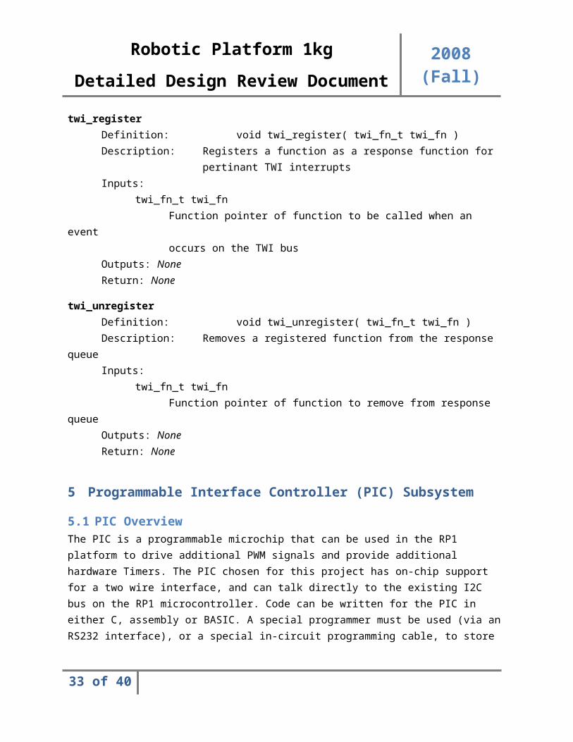
twi_registerDefinition: void twi_register( twi_fn_t twi_fn )Description: Registers a function as a response function for
pertinant TWI interruptsInputs:
twi_fn_t twi_fnFunction pointer of function to be called when an
eventoccurs on the TWI bus
Outputs: NoneReturn: None
twi_unregisterDefinition: void twi_unregister( twi_fn_t twi_fn )Description: Removes a registered function from the response
queueInputs:
twi_fn_t twi_fnFunction pointer of function to remove from response
queueOutputs: NoneReturn: None
5 Programmable Interface Controller (PIC) Subsystem
5.1 PIC OverviewThe PIC is a programmable microchip that can be used in the RP1 platform to drive additional PWM signals and provide additional hardware Timers. The PIC chosen for this project has on-chip support for a two wire interface, and can talk directly to the existing I2C bus on the RP1 microcontroller. Code can be written for the PIC in either C, assembly or BASIC. A special programmer must be used (via an RS232 interface), or a special in-circuit programming cable, to store user code onto the chip’s internal FLASH memory. This approach allows for a very modular and expandable design approach to motor control.
5.2 PWM Generation using Capture Compare RegistersThe PIC utilizes special comparators known as either Capture-Compare-PWM (CCP) modules or Enhanced-Capture-Compare-PWM (ECCP). The CCP module can generate PWM signals to drive the platforms DC or Stepper motors and uses an on-chip digital timer. The ECCP operates in the same manner, but is able to drive one PWM signal to 2 to 4 different output pins, which can be used to control an H-bridge. Since the PICs have built-in PWM support, only relevant control registers need to be set and a duty cycle provided to output PWMs.
27 of 33
Robotic Platform 1kg
2008 (Fall)Detailed Design Review Document
Sample PIC PWM Initialization Code for Two PWMs:
Function: init_pwm_and_timer2
void init_pwm_and_timer2()
{
CCP1CON=0; // Clear existing control register bits for CCP1
CCP2CON=0; // Clear existing control register bits for CCP2
T2CON=0; // Timer2 control register (PostScale|Off|PreScale)
set_bit(T2CON,1); //PreScale 1:16
TMR2=0; // Reset timer2
// set the PWM period by writing to the PR2 register
PR2=0xFF; // period is ((PR2)+1)x(prescale)x(50x4)ns=0.81ms
// set PWM1 duty cycle by writing to CCPR1L register at CCP1CON<4:5>
CCP1CON=0x0C; // 0 -> 2 LSCs of the PWM duty cycle
// C -> PWM Mode
// duty cycle -> 1111 1111 00 = 1020x50xprescale=0.8ms (100%)
CCPR1L=0xFF;
// set PWM2 duty cycle by writing to CCPR2L register at CCP2PON<4:5>
CCP2CON=0x0C; // 0 -> 2 LSCs of the PWM duty cycle
// C -> PWM Mode
// duty cycle -> 1111 1111 00 = 1020x50xprescale=0.8ms (100%)
CCPR2L=0xFF;
//make the CCP2, CCP1 pin an output by clearing the TRISC<1:2> bits
TRISC=TRISC&0xF9;
set_bit(PIE1,1); //Timer2 IE
clear_bit(PIR1,1); //Timer2 clear Interrupt Flag
set_bit(T2CON,2); // Turn ON Timer2
}
After a capture event is triggered, the contents, high and low byte, are recorded in CCPRxH (high byte)
28 of 33
Robotic Platform 1kg
2008 (Fall)Detailed Design Review Document
and CCPRxL (low byte). Also the interrupt flag bit, CCPxIF, is set. If CCPxIF is set and CCPxIE is enabled, the main code execution is paused and the interrupt handler is called. The interrupt handler must clear CCPxIF bit to allow detection of the next capture event condition.
It is important to note that CCPRxH and CCPRxL are only single level buffered, which requires the CCPRx register data be saved to another register before the next consecutive capture event occurs, or the value will be lost.
5.3 Encoder FeedbackPerforming encoder feedback on the PIC instead of the microcontroller can free up comparators and CPU resources that would be spent continuously sampling inputs and at very high rate. Much like PWMs are generated with capture and control registers, the CCP registers can be taken out of PWM mode to sample an external input, such as encoder feedback, instead of triggering off of an internal clock.
5.4 Communication via the I2C BusThe variable duty cycle, period and prescaler can be set by sending data bits from the microcontroller over the I2C bus. The PIC can be configured in I2C slave mode and receive data at any time from the RP1 microcontroller.
Because there is built-in functionality for a two wire interface, using the TWI is as simple as setting control registers, just as the CCP was configured.
Sample I2C Initialization Code for Slave Device:
void init_i2c_slave()
// I2C IE (Serial Port Interrupt) : PIE1<3>
// I2C Interrupt Flag : PIR1<3>
{
set_bit(SSPSTAT,7); // standard speed mode
clear_bit(SSPSTAT,6); // input level conform to I2C spec
clear_bit(SSPSTAT,0); // BF (buffer full) bit
//SCL and SDA as input
set_bit(TRISC,3);
set_bit(TRISC,4);
//SSPCON<5> enable bit (1)
//SSPCON<3:0> 0110 (slave, 7 bit address)
clear_bit(SSPCON,7); // WCOL Write Collision Detect bit
29 of 33
Robotic Platform 1kg
2008 (Fall)Detailed Design Review Document
clear_bit(SSPCON,6); // SSPOV Receive Overflow Indicator bit
set_bit(SSPCON,5); // Synchronous Serial Port Enable
set_bit(SSPCON,4); // CKP
clear_bit(SSPCON,3); //0110: I2C slave mode: 7 bit address
set_bit(SSPCON,2);
set_bit(SSPCON,1);
clear_bit(SSPCON,0);
SSPADD=0x0E; // 0000 1110 -> 7 bit address= 0000 111
//SSP IE
set_bit(PIE1,3);
clear_bit(PIR1,3); //Interrupt flag
}
The code will now test if it's an incoming message, or a request for a transmission with the SSPSTAT register. If it's a reception, it will read the SSPBUFF register (or else it will stop the I2C interrupt handler). If it's a transmission, write in the SSPBUFF register. Regardless of a transmission or a reception, the interrupt flag (here PIR1:3) is always reset.
void i2c_slave_interrupt()
{
if (SSPSTAT&0x04)
{
//I2C Slave Transmission
SSPBUFF=0;
set_bit(SSPCON,4); // CKP, SSPBUFF must be written
clear_bit(PIR1,3); //reset the interrupt flag
}
else
{
//I2C Slave Reception
tempI2C=SSPBUFF;
30 of 33
Robotic Platform 1kg
2008 (Fall)Detailed Design Review Document
clear_bit(PIR1,3); //reset the interrupt flag
}
}
Through this approach, many PICs can be added onto the existing I2C bus to drive as many motor modules as needed. This is essential since the ATmega128 can only drive 6 PWM signals with its own hardware, and only has 3 available Timers. The use of PICs will further free up processing time and resources on the microcontroller so that these can be used towards running the Command Line Interface, encoder feedback monitoring, and other services as fast and efficiently as possible.
5.5 In-Circuit Serial Programming (ICSP)One important feature that is built in to the PIC is the ability to program new operational code into the device without needing to remove it from the existing circuit. By simply providing five leads from the PIC to the ICSP connector, new code can be easily programmed without any additional circuit modifications.
Figure 5 – Schematic For ICSP Connector
Where MCLR is connected to an RC circuit and a Schottkey diode, VDD is provided a pull-up resistor, VSS is ground and RB6/RB7 are dedicated serial programming pins. The ICSP connector is simply a 5 pin connector interface to a serial device.
6 Feasibility
6.1 Standing Issues1. Jason is currently unable to drive the stepper motor using the microcontroller.2. The Hardware, Software and Interface control documents must be completed.
31 of 33
Robotic Platform 1kg
2008 (Fall)Detailed Design Review Document
3. Encoder feedback accuracy must be balanced with tying up the microcontroller interrupts. A compromise must be decided on.
4. All PCBs must be created in addition to the Interconnect schematic.5. Ordering the remaining parts (motors, encoders, etc…)6. The PCBs may not be large enough to support the required connector size.7. The microcontroller currently limits us to only 4 motors (2 DC and 2 Servo) due to limited PWM
hardware lines and Timer.
6.2 Issue Resolution Plan1. Issue will be addressed in SDII if necessary.2. The ICD, HCD and SCD are all started and will be continually worked on and revised in the following
weeks. Subsections will be populated as they are addressed.3. A system is currently being prototyped to reduce the strain on the microprocessor by sampling the
encoder feedback at a lower rate while retaining accuracy.4. Only PIC and Interconnect PCBs remain. The PIC PCB does not need to be completed for SDI.5. Component choices have been finalized. Some part must still be ordered.6. Smallest PCB possible may not be large enough to support all required connectors. May need to be
larger for this reason alone.7. External chips (PICs) will be utilized in SDII to drive additional PWMs and Timers. The PICs can
interface with the existing I2C bus.
7 AcronymsAcronym Description
RP1 Robotic Platform 1ICD Interface Control DocumentGUI Graphical User InterfaceJRE JAVA Runtime EnvironmentCLI Command Line Interface
OpSoft Operational SoftwareRTOS Real Time Operating System
PC Personal Computer (Desktop or Laptop)SCD Software Control Document
Figure 6 - Table of Acronyms
8 Document ReferencesDocument Location or Link
Customer Needs https://edge.rit.edu/content/P09204/public/Needs%20Assessment%20%28Week%204%29.pdf?rev=0
Design Specifications https://edge.rit.edu/content/P09204/public/Design%20Specifications%20%28Week%204%29.pdf?rev=0
Software Control Document
http://edge.rit.edu/content/P09204/public/Software%20Control%20Document.pdf
32 of 33
Robotic Platform 1kg
2008 (Fall)Detailed Design Review Document
Figure 7 - Table of References
33 of 33