Embed Size (px)
Citation preview
ANSYS ADVANTAGE Volume IX | Issue 2 | 2015 13© 2015 ANSYS, INC.
ROBUST ELECTRONIC SYSTEMS
TEST DRIVE FOR EMI
By Arnaud Christophe Pierre Marie Colin, Lead EMC Designer; Artur Nogueira de São José, EMC Engineer; and Ana Carolina Silveira Veloso, EMC Engineer, Fiat Chrysler Latin America, Betim, Brazil Juliano Fujioka Mologni, Lead Application Engineer, ESSS, BrazilMarkus Kopp, Lead Application Specialist, ANSYS
Automotive electromagnetic interference and compatibility can be determined more efficiently using new technology within ANSYS HFSS.
product integrity by investigating potential EMI on its vehicles using ANSYS HFSS and full-vehicle testing.
Because electronics have been rapidly added to automo-biles, a number of guidelines have been developed, including legislation, industry association standards and even regulatory limits that are specific to a particular automotive manufacturer. One of the earliest industry directives was issued in Europe in
A utomobiles are fast becoming mobile hotspots. Components such as wireless links, multimedia devices, electronic control modules and hybrid/elec-
tric drives are continually being added to vehicles, which makes designing for electromagnetic interference (EMI) and electro-magnetic compatibility (EMC) increasingly important. At Fiat Chrysler in Brazil, a team of engineers is certifying the complete
As automobiles become mobile hotspots and electronic components are continually added to vehicles, designing for EMI and EMC becomes increasingly important.
ANSYS ADVANTAGE Volume IX | Issue 2 | 2015 14© 2015 ANSYS, INC.
1972 to deal with electronic spark plug noise; since then, many organizations have created a variety of standards spe-cifically for the automotive industry.
Many standards, directives and regulations are designed with vehi-cle safety in mind. This ensures that all onboard systems continue to func-tion properly during exposure to EMI and then return to normal, either auto-matically or by a manual reset opera-tion after exposure. A major concern for Fiat Chrysler’s engineers is the amount of wires a car now contains ― as much as 5 kilometers per vehicle. While cabling is an obvious source of EMI, there are a number of other sources in modern vehicles that are packed with electronics. In addition, drivers introduce potential EMI sources in the form of mobile phones, tab-lets and Bluetooth®-enabled devices. Automobile manufacturers that create smart vehicles need to meet standards to reduce risk of failure.
Conventional EMI/EMC procedures and techniques are no longer appro-priate for the latest generation of elec-tronic devices and components. A few automotive standards have been devel-oped that use laboratory tests in an attempt to reduce the probability of EMI occurring in vehicles. One impor-tant international lab-based standard is ISO 11451-2. This standard calls for testing a source antenna that radiates throughout the vehicle in an anechoic (echo-free) chamber; the performance of all electronic subsystems must not be affected by the electromagnetic distur-bance generated by the source antenna.
ISO 11451-2 is meant to determine the immunity of private and commercial road vehicles to electrical disturbances from off-vehicle radiation sources, regardless of the vehicle propulsion sys-tem (including hybrid/electric vehicles). The test procedure prescribes perfor-mance on a full vehicle in an absorber-lined, shielded enclosure, creating a test environment that represents open-field testing. For this test, the floor generally is not covered with absorbing material, but such covering is allowed.
Testing for the standard consists of generating radiated electromagnetic fields using a source antenna with radio frequency (RF) sources capable of pro-ducing the desired field strengths rang-ing from 25 V/m to 100 V/m and beyond. The test covers the range of frequencies from 10 kHz to 18 GHz. During the pro-cedure, all embedded electronic equip-ment must perform flawlessly. This flawless performance also applies to the frequency sweep of the source antenna.
Physically performing the ISO 11451-2 standard test can be a time-consuming process that requires costly equipment and access to an expensive test facility. Numerical simulation can be a cost-effective, alternative means to reduce the product design cycle and its associated R&D costs. Full-vehicle finite element method (FEM) simulation has become possible within the past few years using the domain decomposition method (DDM), which was pioneered by ANSYS HFSS software. DDM paral-lelizes the entire simulation domain by creating a number of subdomains, each solved on different computing cores or
various computers connected to a net-work. While DDM allows engineers to simulate entire vehicles, there is another approach available within HFSS for solv-ing large electromagnetic structures: a hybrid finite element−boundary integral (FE-BI) methodology.
FE-BI uses an integral equation (IE)–based solution as a truncation boundary for the FEM problem space, thus bring-ing together the best of FEM and IE. This combination of solution paradigms allows Fiat Chrysler engineers to dra-matically reduce the simulation’s solu-tion volume from that required by the FEM method. Because the distance from radiator to FE-BI boundary can be arbi-trarily small, solution time is decreased, as is the overall computational effort.
To demonstrate the capability of the FE-BI methodology, the Fiat Chrysler team worked with ESSS, the ANSYS chan-nel partner in South America, to conduct
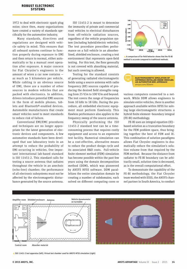
�A comparison of far-field behavior shows that the FE-BI method is accurate compared to traditional methods.
Vehicle dynamometer on turntable
Absorber material
Shielded enclosure
Control room
Amplifier room Antenna
�ISO 11451-2 test apparatus (left). Virtual test chamber used for ANSYS HFSS simulation (right)
ROBUST ELECTRONIC SYSTEMS
ELECTROMAGNETIC SIMULATION OF ANTENNAS INSTALLED INSIDE VEHICLES: AN AUTOMOTIVE EMC APPROACH
ansys.com/92emi
ANSYS ADVANTAGE Volume IX | Issue 2 | 2015 15© 2015 ANSYS, INC.
a full-vehicle simulation using the FE-BI capability. The team then applied the results to the ISO 11451-2 standard to determine EMI of an electronic sub-system. For the simulation, the team reduced the large air region in the test chamber to two much smaller air boxes that more closely conformed to the structures they contained. The surfaces of these air regions were located close to the antenna and the vehicle.
Fiat Chrysler engineers did not model the absorber elements in this simulation because the IE boundary in FE-BI is equivalent to a free-space sim-ulation, which is the same as absorbing material used in a physical measure-ment. The total computation time of just 28 minutes represents more than a 10-fold speedup when compared to a traditional FEM solution. Additionally, the total amount of RAM required for the FE-BI simulation was 6.8 GB, which is also more than a 10-fold decrease compared to previous work using FEM.
Solution results using the FE-BI method showed that the predictions for
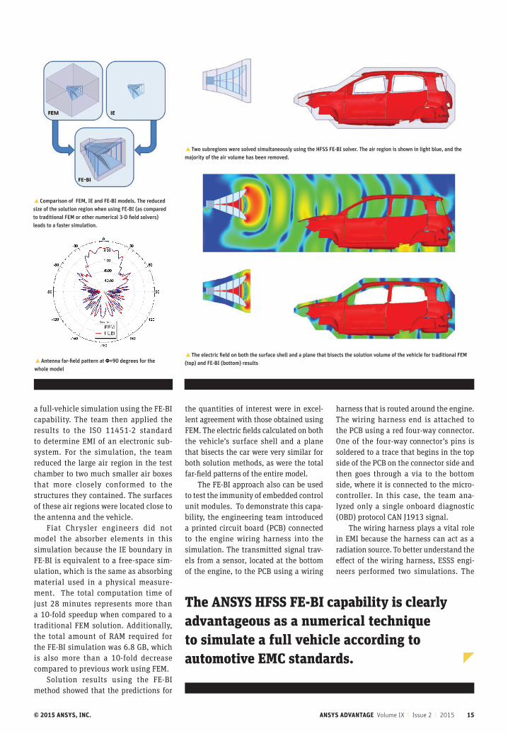
the quantities of interest were in excel-lent agreement with those obtained using FEM. The electric fields calculated on both the vehicle’s surface shell and a plane that bisects the car were very similar for both solution methods, as were the total far-field patterns of the entire model.
The FE-BI approach also can be used to test the immunity of embedded control unit modules. To demonstrate this capa-bility, the engineering team introduced a printed circuit board (PCB) connected to the engine wiring harness into the simulation. The transmitted signal trav-els from a sensor, located at the bottom of the engine, to the PCB using a wiring
harness that is routed around the engine. The wiring harness end is attached to the PCB using a red four-way connector. One of the four-way connector’s pins is soldered to a trace that begins in the top side of the PCB on the connector side and then goes through a via to the bottom side, where it is connected to the micro-controller. In this case, the team ana-lyzed only a single onboard diagnostic (OBD) protocol CAN J1913 signal.
The wiring harness plays a vital role in EMI because the harness can act as a radiation source. To better understand the effect of the wiring harness, ESSS engi-neers performed two simulations. The
�Two subregions were solved simultaneously using the HFSS FE-BI solver. The air region is shown in light blue, and the majority of the air volume has been removed.
�The electric field on both the surface shell and a plane that bisects the solution volume of the vehicle for traditional FEM (top) and FE-BI (bottom) results�Antenna far-field pattern at Φ=90 degrees for the
whole model
�Comparison of FEM, IE and FE-BI models. The reduced size of the solution region when using FE-BI (as compared to traditional FEM or other numerical 3-D field solvers) leads to a faster simulation.
The ANSYS HFSS FE-BI capability is clearly advantageous as a numerical technique to simulate a full vehicle according to automotive EMC standards.
ANSYS ADVANTAGE Volume IX | Issue 2 | 2015 16© 2015 ANSYS, INC.
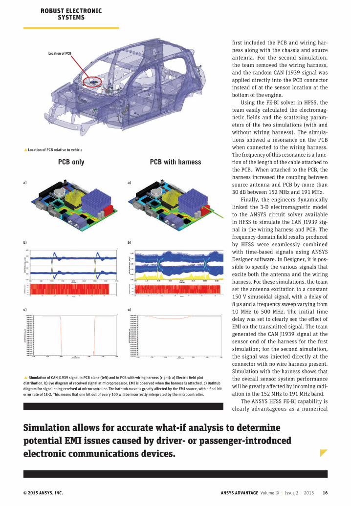
first included the PCB and wiring har-ness along with the chassis and source antenna. For the second simulation, the team removed the wiring harness, and the random CAN J1939 signal was applied directly into the PCB connector instead of at the sensor location at the bottom of the engine.
Using the FE-BI solver in HFSS, the team easily calculated the electromag-netic fields and the scattering param-eters of the two simulations (with and without wiring harness). The simula-tions showed a resonance on the PCB when connected to the wiring harness. The frequency of this resonance is a func-tion of the length of the cable attached to the PCB. When attached to the PCB, the harness increased the coupling between source antenna and PCB by more than 30 dB between 152 MHz and 191 MHz.
Finally, the engineers dynamically linked the 3-D electromagnetic model to the ANSYS circuit solver available in HFSS to simulate the CAN J1939 sig-nal in the wiring harness and PCB. The frequency-domain field results produced by HFSS were seamlessly combined with time-based signals using ANSYS Designer software. In Designer, it is pos-sible to specify the various signals that excite both the antenna and the wiring harness. For these simulations, the team set the antenna excitation to a constant 150 V sinusoidal signal, with a delay of 8 µs and a frequency sweep varying from 10 MHz to 500 MHz. The initial time delay was set to clearly see the effect of EMI on the transmitted signal. The team generated the CAN J1939 signal at the sensor end of the harness for the first simulation; for the second simulation, the signal was injected directly at the connector with no wire harness present. Simulation with the harness shows that the overall sensor system performance will be greatly affected by incoming radi-ation in the 152 MHz to 191 MHz band.
The ANSYS HFSS FE-BI capability is clearly advantageous as a numerical
� Simulation of CAN J1939 signal in PCB alone (left) and in PCB with wiring harness (right): a) Electric field plot distribution. b) Eye diagram of received signal at microprocessor. EMI is observed when the harness is attached. c) Bathtub diagram for signal being received at microcontroller. The bathtub curve is greatly affected by the EMI source, with a final bit error rate of 1E-2. This means that one bit out of every 100 will be incorrectly interpreted by the microcontroller.
PCB only
a)
b)
c)
PCB with harness
a)
b)
c)
�Location of PCB relative to vehicle
Simulation allows for accurate what-if analysis to determine potential EMI issues caused by driver- or passenger-introduced electronic communications devices.
ROBUST ELECTRONIC SYSTEMS

ANSYS ADVANTAGE Volume IX | Issue 2 | 2015 17© 2015 ANSYS, INC.
technique to simulate a full vehicle according to automotive EMC stan-dards. The FE-BI technique was over 10 times faster and required 10 times less computational effort than a tradi-tional FEM simulation. As a result, EMI/EMC engineers can begin to simulate entire vehicles and their subsystems in virtual anechoic chambers to meet EMC and EMI standards. Using simu-lation also allows for accurate what-if analysis to help determine potential EMI issues caused by driver- or pas-senger-introduced electronic commu-nications devices. It also leads to a better understanding of transient noise issues caused by the myriad of motors included in every vehicle.
�Point where wiring harness attaches to PCB
� S–matrix with PCB, both alone and connected to wire harness
Fast to get started. Fast to compute.Fast to see results. Nimbix delivers seamlesscloud computing power to ANSYS customers to push product simulation to the next level.
nimbix.net
simulation atsupercomputing speed?
simple.
supercomputing made super human