Embed Size (px)
Citation preview
International Journal of Applied Power Engineering (IJAPE)
Vol. 9, No. 3, December 2020, pp. 284~296
ISSN: 2252-8792, DOI: 10.11591/ijape.v9.i3.pp284-296 284
Journal homepage: http://ijape.iaescore.com
Robust maximum power point tracking control for photovoltaic
system based on second order sliding-mode
A. Fezzani1, N. Bouarroudj2, S. Drid3, L. Zaghba4
1,2,4Unité de Recherche Appliquée en Energies Renouvelables, URAER, Centre de Développement des Energies
Renouvelables, CDER, Algeria 3LSPIE, Laboratory, Electrical Engineering Department, University of Batna 2, Algeria
Article Info ABSTRACT
Article history:
Received Feb 4, 2020
Revised Feb 19, 2020
Accepted Mar 20, 2020
This paper proposes a control approach of a maximum power point of
a photovoltaic (PV) system using the second order sliding mode approach.
The main objective of the proposed paper is to track the maximum power
point (MPP) using super twisting algorithm (STA) with a one-loop control
method and augment efficiency of the output power system. The structure of
a proposed approach is simple and robust aging the atmospheric changes.
Such control approach solution has several advantages such as simple
implementation, robustness; reduce the chattering phenomenon and good
dynamic response compared to traditional first-order sliding mode control
algorithm. The controller circuit adapts the duty cycle of the switch
electronic device of the DC/DC converter to search maximum power point
tracking as a function of evolution of the power input. The effectiveness
and feasibility of the proposed control are verified by simulation in
MATLAB/Simulink environment and dSPACE-based hardware in loop platform.
Keywords:
dDSPACE controller board
Maximum power point
Shell Solar S75 PV
Sliding mode control
Super twisting algorithm
This is an open access article under the CC BY-SA license.
Corresponding Author:
Amor Fezzani,
Unité de Recherche Appliquée en Energies Renouvelables, URAER,
Centre de Développement des Energies Renouvelables,
CDER, 47133, Ghardaïa, Algeria.
Email: [email protected]
1. INTRODUCTION
Solar energy represents a viable energy alternative for the production of electricity since the latter is
a renewable source, both clean, unlimited and with a very low level of risk [1-3]. However, a major challenge
in using an energy generated by photovoltaic systems is to undertake its nonlinear output characteristics,
which depend of solar insolation and temperature module. An important in the operation of a PV generator is
to reach the maximum output power by means of continuously correcting the PV array operating point for
the given conditions. The main objective of maximum power point tracking (MPPT) method is to
automatically obtain an optimal MPP operation under real outdoor conditions.
Several MPPT techniques have been developed in literature. Some of the popular schemes are
the Open-circuit voltage method [4], incremental conductance methods [5, 6] and perturb and observer
(P&O) methods [7]. In the open circuit voltage technique, in order to calculate VOC, power inverter should be
turned off for a few seconds. Thus, at each calculation, some power is lost. Another drawback of this
technique is that it cannot track MPP at the effects of the irradiation changes. The P&O is most widely due to
its simplicity and easily implemented. However, P&O have major disadvantage because he does not consider
the effects when the atmospheric conditions change rapidly [8, 9]. Incremental conductance can perform
MPPT faster under different atmospheric conditions with high accuracy but it increase system complexity.
Int J Appl Power Eng ISSN: 2252-8792
Robust maximum power point tracking control for photovoltaic system based on second order… (A. Fezzani)
285
There are also other algorithms such as the artificial neutral network technique (ANN) [10], particle
swarm optimization (PSO) [11], fuzzy logic approach [12] and adaptive neuron-fuzzy technique [13].
The algorithms should have a high performance to MPP track. However, their implementations are expensive
and complex [14]. In that sense, robust Sliding Mode Control is an interesting solution for non-linear control
derived from variable structure control (VSC) system theory and developed by UTKIN [15]. Such controller
has many advantages for example, simple implementation, well dynamic response and good robustness.
VSC technique for PV application was proposed and evaluated by numerical study in [16].
Further study was also suggested in [17-19], however, these approaches required current or a voltage
reference for control law synthesis and can lead to a lack of robustness to operation conditions. In [20] there
is no necessity to have a reference value since the sliding surface guarantees the MPP when it is
equal to zero. But the chattering phenomenon, originated by the interaction between parasite dynamic and
finite-frequency switching control is the main disadvantages of this techniques of control [21, 22].
To minimize chattering phenomena some methods were proposed [23-25]. To preserve the main advantages
of the sliding mode technique and to reduce the chattering phenomenon, a novel class of SMC algorithm,
called second-order SMC algorithm (2-SMC) has been proposed in [26, 27].
In Saharaoui et al. [28], a 2-SMC was applied with a two-loop control approach. A simulation study
by Yatimi et al., [29] presents a robust sliding mode method for a photovoltaic energy storage system.
Another method to track the MPP given in Mojallizadeh et al., [30], the proposed scheme is based on
the second-order fuzzy sliding mode control law of photovoltaic power generation systems with a two-loop
control. Moreover, in Kckaou et al., [31] offer a second-order sliding MPPT control for photovoltaic
application. The main objective of this work is the use one loop technique of 2-SMC based on super twisting
algorithm to extract MPP, reduce the chattering phenomenon and real-time implementation study under
different operating scenarios. The control circuit use an algorithm to adapt the duty cycle of the switch
control of the DC-DC converter to search MPP tracking as a function of evolution of the power input.
This paper consists of four sections, including the introduction. Section 2 materials and methods, and section 3
results and discussion. Finally, the conclusions of the study are given in section 4.
2. MATERIALS AND METHODS
2.1. Photovoltaic systems
2.1.1. Mathematical modelling and simulation
The physical behaviour of the panel has conventionally been studied by representing it as an equivalent
electrical circuit composed of linear and non-linear components. Solar cell (SPV) is the elementary
component which converts the energy of light directly into electricity by the PV effect. PV arrays are built up
with combined series/parallel combinations of SPV [32, 33]. Each cell is typically a p-n junction. There are
various circuit schemes for a photovoltaic cell in literature. A single diode model is considered as the
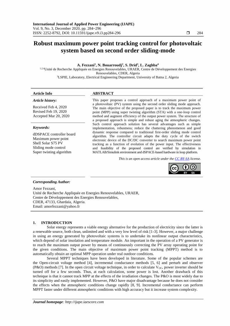
equivalent photovoltaic cell in the present paper [33]. The basic model for a photovoltaic cell is show in
Figure 1.
Figure 1. Simplified equivalent circuit PV model
The one diode equivalent circuit determines the I-V characteristic of the cell is described by
the following (1):
I = Iph − I0 [e(V+IRsVt
)− 1] −
V+IRs
Rsh (1)
where I is the cell output current (A), V is the cell output voltage (V), Iph is the photocurrent, function of
the irradiation level (G) and junction temperature, I0 is the reverse saturation current of diode, Vt=aKTc/q is
the thermal voltage, q is the electron charge (1.602×10⁻¹⁹C), K is the Boltzmann constant (1.38×10⁻²³J/K), a is
ISSN: 2252-8792
Int J Appl Power Eng, Vol. 9, No. 3, December 2020: 284 – 296
286
the ideal factor, Tc is the temperature of the cell, Rs and Rsh the serial and parallel resistances respectively
and Id, called diode (D) current or dark current. The photocurrent Iph can be assessed with the (2):
Iph = ISTCG
GSTC[1 + α(Tc − Tc,STC)] (2)
where ISTC is the short circuit current at standard test condition (STC), while GSTC and Tc,STC are
the irradiation and temperature of the PV cell at STC, respectively; α is the current temperature coefficient.
With regard to the reverse saturation current I0 parameter, its value changes with cell temperature at STC
conditions and can be found by using the following (3).
I0 = Irs (Tc
Tc,STC)3
eqEg(1Tc−
1Tc,STC
)
Ka (3)
where Irs is the reverse saturation current at STC conditions, Eg is the band-gap energy of the material. In this
work for Rs and Rsh the same relations in [34] are used as (4) and (5).
Rsh = Rsh,STCG
GSTC (4)
Rs = Rs,STC (5)
where Rs,STC and Rsh,STC are the serial resistance and parallel resistance at STC conditions, respectively.
In (1) is valid for a solar cell. For the exact application of this equation for PV module,
the term of (𝑉 + 𝑅𝑠𝐼) is replaced by (𝑉+𝑁𝑠𝑅𝑠𝐼)
𝑁𝑠. To determine the five parameters exist in (1), which are: 𝐼𝑝ℎ,
𝑅𝑠, 𝑅𝑠ℎ, 𝐼0 and a, you can see [35, 36]. Typically Ns cells are connected in series to get the requisite voltage
of PV module. All the cells are forced to carry the same current called panel current in series panel. In this
work, actual module was utilised, Shell Solar S75. The electrical parameters of the module under STC form
manufacturer are listed in Table 1.
Table 1. Data of experimental PV modules Silicon type Shell solar S75
Open circuit voltage (Voc) 21.6 V
Short-circuit current (Isc) 4.7 A
Maximal voltage (Vmp) 17.6 V Maximal current (Imp) 4.26 A
Maximal power (Pmp) 75 W
Number of cells (Ns) 36
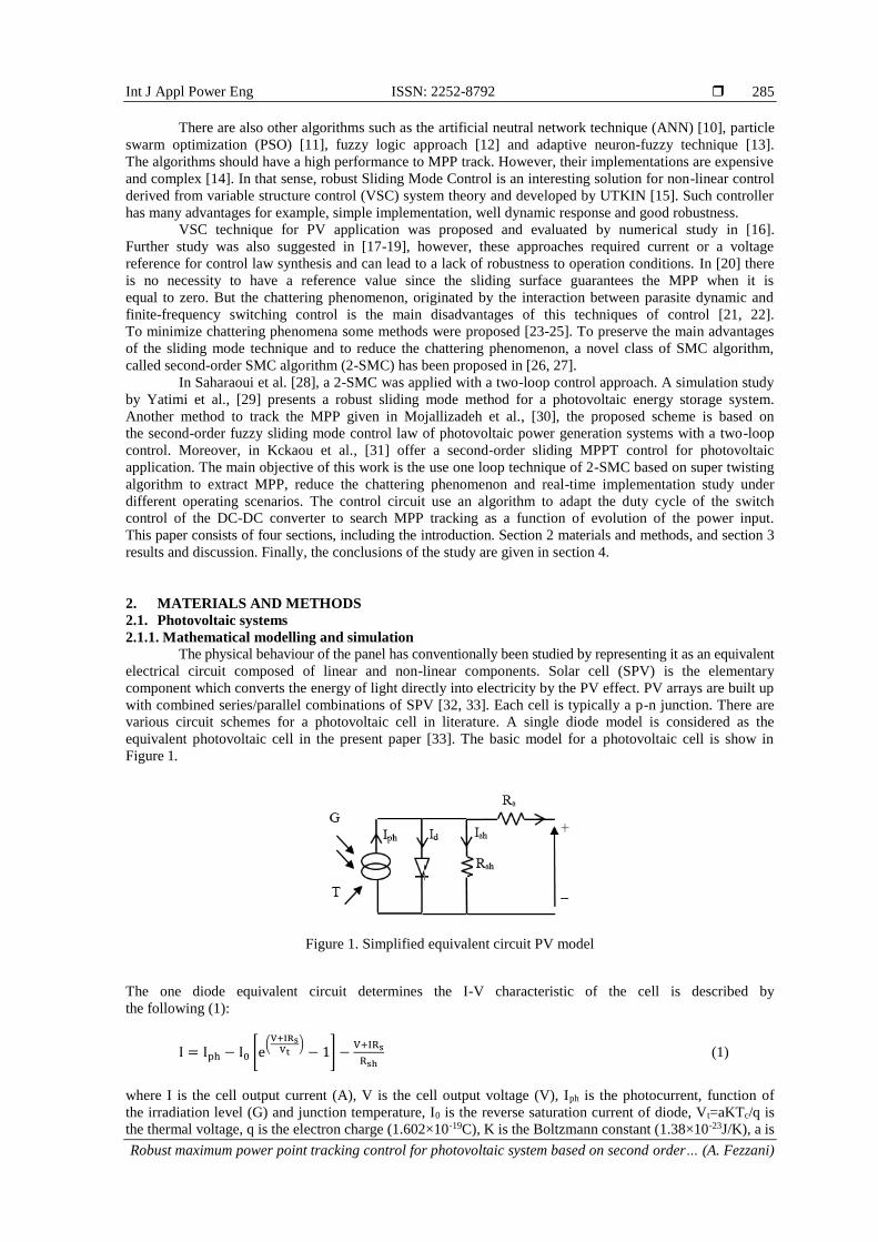
Figure 2 shows the simulated and experimental results of the module under different irradiation and
temperature levels. The current-voltage (I-V) and power-voltage (P-V) characteristics are shown in Figure 2.
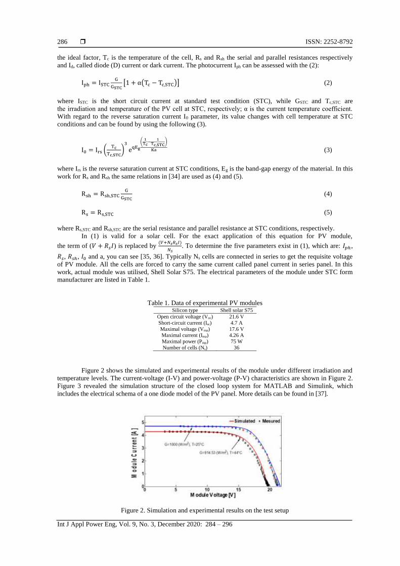
Figure 3 revealed the simulation structure of the closed loop system for MATLAB and Simulink, which
includes the electrical schema of a one diode model of the PV panel. More details can be found in [37].
Figure 2. Simulation and experimental results on the test setup
Int J Appl Power Eng ISSN: 2252-8792
Robust maximum power point tracking control for photovoltaic system based on second order… (A. Fezzani)
287
Figure 3. Simulink simulations to illustrate the I-V and P-V module output characteristics
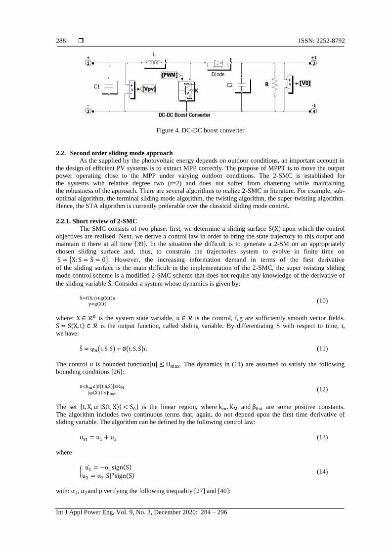
2.1.2. Dynamic model of DC/DC boost converter
In order to force the PV panel functions at the MPPT, we present the principle of the DC-DC boost
converter. This type of converter use inductors and capacitors to control the energy flow the PV module to
load by continuously opening and closing a switch (K) [38]. The switch is generally an electronic device
(Mosfet or IGBT transistor). It is driven by a pulse width modulation (PWW) signal with a fixed frequency
and an adjustable duty cycle D (0<D<1). Figure 4 shows a DC-DC boost converter. The relation between
the output voltage and input voltage in DC-DC boost converter is given by (6):
𝑉0 =1
1−𝐷𝑉𝑝𝑣 (6)
the dynamic of the boost converter is given by:
C1
dVpv
dt= Ipv − IL
LdIL
dt= Vpv − (1 − D)V0
C2dV0
dt= −I0 + (1 − D)IL
(7)
where Vpv and Ipv: are the voltage and current of the PV module, IL: the inductor current of the DC-DC
converter. V0: the DC-DC converter output voltage, D: the duty cycle, L: the filter inductor, C1 and C2: the filter
capacitor, R: the nominal resistance of load.
By combing the different equations describing the system [29], global dynamic model can be
written as follows:
I = Iph − I0 [e
(V+INsRsVtNs)− 1] −
V+INsRs
NsRshdVpv
dt=
Ipv
C1−
IL
C1dVpv
dt=
Vpv
L−(1−D)
LV0
dV0
dt= −
I0
C2+(1−D)
C2IL
(8)
In (8) can be written in compact form of the nonlinear time invariant system;
X1 =
Ipv
C1−
1
C1X2
X2 = 1
LX1 −
u
LX3
X3 = −1
RC2X3 +
u
C2X2
(9)
where X1 = Vpv; X2 = IL; X3 = V0; u = (1 − D); I0 = V0 R⁄ .
ISSN: 2252-8792
Int J Appl Power Eng, Vol. 9, No. 3, December 2020: 284 – 296
288
Figure 4. DC-DC boost converter
2.2. Second order sliding mode approach As the supplied by the photovoltaic energy depends on outdoor conditions, an important account in
the design of efficient PV systems is to extract MPP correctly. The purpose of MPPT is to move the output
power operating close to the MPP under varying outdoor conditions. The 2-SMC is established for
the systems with relative degree two (r=2) and does not suffer from chattering while maintaining
the robustness of the approach. There are several algorithms to realize 2-SMC in literature. For example, sub-
optimal algorithm, the terminal sliding mode algorithm, the twisting algorithm, the super-twisting algorithm.
Hence, the STA algorithm is currently preferable over the classical sliding mode control.
2.2.1. Short review of 2-SMC
The SMC consists of two phase: first, we determine a sliding surface S(X) upon which the control
objectives are realised. Next, we derive a control law in order to bring the state trajectory to this output and
maintain it there at all time [39]. In the situation the difficult is to generate a 2-SM on an appropriately
chosen sliding surface and, thus, to constrain the trajectories system to evolve in finite time on
S = X: S = S = 0. However, the increasing information demand in terms of the first derivative
of the sliding surface is the main difficult in the implementation of the 2-SMC, the super twisting sliding
mode control scheme is a modified 2-SMC scheme that does not require any knowledge of the derivative of
the sliding variable S. Consider a system whose dynamics is given by:
X=f(X,t)+g(X,t)u
y=g(X,t) (10)
where: X ∈ ℛn is the system state variable, u ∈ ℛ is the control, f, g are sufficiently smooth vector fields.
S = S(X, t) ∈ ℛ is the output function, called sliding variable. By differentiating S with respect to time, t,
we have:
S = φA(t, S, S) + ∅(t, S, S)u (11)
The control u is bounded function|u| ≤ Umax. The dynamics in (11) are assumed to satisfy the following
bounding conditions [26]:
0<km≤|∅(t,S,S)|≤KM
|φ(X,t)|≤β0st (12)
The set t, X, u: |S(t, X)| < S0 is the linear region, where km, KM and β0st are some positive constants.
The algorithm includes two continuous terms that, again, do not depend upon the first time derivative of
sliding variable. The algorithm can be defined by the following control law:
ust = u1 + u2 (13)
where
u1 = −α1sign(S)
u2 = α2|S|ρsign(S)
(14)
with: α1, α2and ρ verifying the following inequality [27] and [40]:
Int J Appl Power Eng ISSN: 2252-8792
Robust maximum power point tracking control for photovoltaic system based on second order… (A. Fezzani)
289
α1 =
β0st
km
α22 =
4β0stKm(α1+β0st)
KM2 km(α1−β0st)
0 < 𝜌 ≤ 0
(15)
The choice ρ = 0.5 ensures that he maximal possible for 2-Sliding mode control realization real sliding order
two is achieved. Using 2-SMC assures the finite time convergence.
2.2.2. Robust 2-SMC MPPT control approach
In this work the STA has been designed to search MPP. The super twisting algorithm is established
for the system with relative degree one so as to reduce the chattering [31]. To make sure that the system
states will hit the sliding surface and provides the MPP output, we choose the sliding surface as given in [19].
The state (9) can be expressed by:
X=f(X,t)+g(X,t)u
S(X,t)=∂Ppv
∂Vpv
(16)
where X = [Ipv V0]T ,u = [0 1]. The sliding mode surface S (t) is defined as:
S(X, t) =∂Ppv
∂Vpv= Ipv + Vpv
∂𝐼pv
∂Vpv= 0 (17)
If we differentiate the sliding surface S, we can write [29]:
S = φA(t, S, S) + ∅(t, S, S)u (18)
with
φA(t, S, S) = (∂3Ppv
∂Vpv3 ) (
∂Vpv
∂t)2
+1
C1(∂2Ppv
∂Vpv2 ) [(
∂Ipv
∂Vpv) (
∂Vpv
∂t) −
Vpv
L] (19)
∅(t, S, S) =1
C1(∂2Ppv
∂Vpv2 )
V0
L (20)
where
∂2Ppv
∂Vpv2 =2
∂Ipv
∂Vpv+Vpv
∂2Ipv
∂Vpv2
∂3Ppv
∂Vpv3 =3
∂2Ipv
∂Vpv2 +Vpv
∂3Ipv
∂Vpv3
(21)
The control of the boost converter is a bounded function (0<u<1). We assume that the (18) satisfy
condition in (15), the control law guarantees the finite time convergence. The proof of the control law
algorithm approach is presented in the appendix. We can consider the applied control law and D can be
deduced from the equation u=1-D, it is guaranteed that the system state will hit the surface and produce
maximum power output persistently.
3. RESULTS AND DISCUSSION
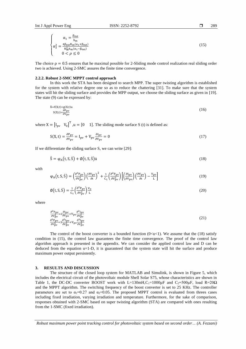
The structure of the closed loop system for MATLAB and Simulink, is shown in Figure 5, which
includes the electrical circuit of the photovoltaic module Shell Solar S75, whose characteristics are shown in
Table 1, the DC-DC converter BOOST work with L=130mH,C1=1000µF and C2=500µF, load R=20Ω
and the MPPT algorithm. The switching frequency of the boost converter is set to 25 KHz. The controller
parameters are set to α1=0.27 and α2=0.05. The proposed MPPT control is evaluated from threes cases
including fixed irradiation, varying irradiation and temperature. Furthermore, for the sake of comparison,
responses obtained with 2-SMC based on super twisting algorithm (STA) are compared with ones resulting
from the 1-SMC (fixed irradiation).
ISSN: 2252-8792
Int J Appl Power Eng, Vol. 9, No. 3, December 2020: 284 – 296
290
Figure 5. Simulink structure of the closed loop control of boost converter
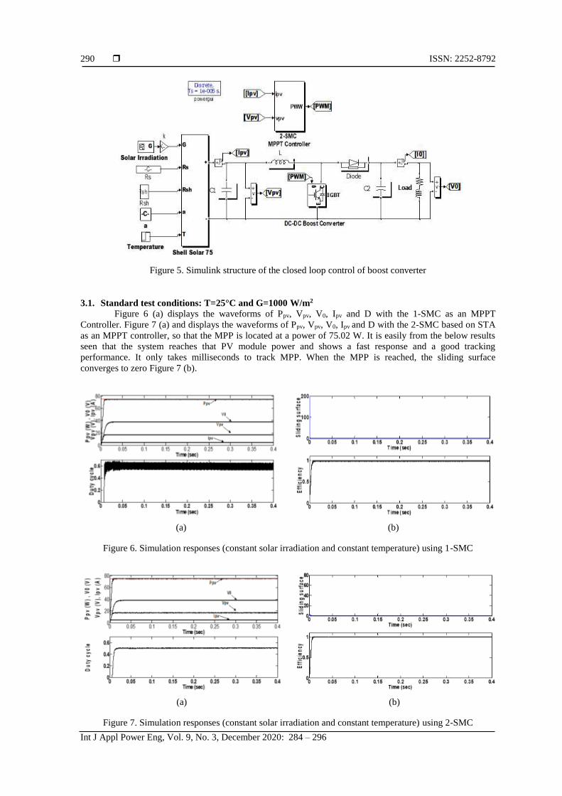
3.1. Standard test conditions: T=25°C and G=1000 W/m2
Figure 6 (a) displays the waveforms of Ppv, Vpv, V0, Ipv and D with the 1-SMC as an MPPT
Controller. Figure 7 (a) and displays the waveforms of Ppv, Vpv, V0, Ipv and D with the 2-SMC based on STA
as an MPPT controller, so that the MPP is located at a power of 75.02 W. It is easily from the below results
seen that the system reaches that PV module power and shows a fast response and a good tracking
performance. It only takes milliseconds to track MPP. When the MPP is reached, the sliding surface
converges to zero Figure 7 (b).
(a) (b)
Figure 6. Simulation responses (constant solar irradiation and constant temperature) using 1-SMC
(a) (b)
Figure 7. Simulation responses (constant solar irradiation and constant temperature) using 2-SMC
Int J Appl Power Eng ISSN: 2252-8792
Robust maximum power point tracking control for photovoltaic system based on second order… (A. Fezzani)
291
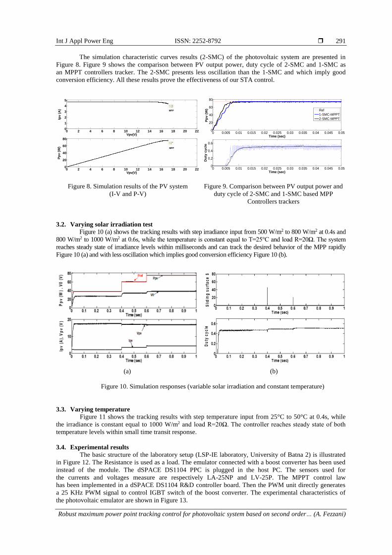
The simulation characteristic curves results (2-SMC) of the photovoltaic system are presented in
Figure 8. Figure 9 shows the comparison between PV output power, duty cycle of 2-SMC and 1-SMC as
an MPPT controllers tracker. The 2-SMC presents less oscillation than the 1-SMC and which imply good
conversion efficiency. All these results prove the effectiveness of our STA control.
Figure 8. Simulation results of the PV system
(I-V and P-V)
Figure 9. Comparison between PV output power and
duty cycle of 2-SMC and 1-SMC based MPP
Controllers trackers
3.2. Varying solar irradiation test
Figure 10 (a) shows the tracking results with step irradiance input from 500 W/m2 to 800 W/m2 at 0.4s and
800 W/m2 to 1000 W/m2 at 0.6s, while the temperature is constant equal to T=25°C and load R=20Ω. The system
reaches steady state of irradiance levels within milliseconds and can track the desired behavior of the MPP rapidly
Figure 10 (a) and with less oscillation which implies good conversion efficiency Figure 10 (b).
(a) (b)
Figure 10. Simulation responses (variable solar irradiation and constant temperature)
3.3. Varying temperature
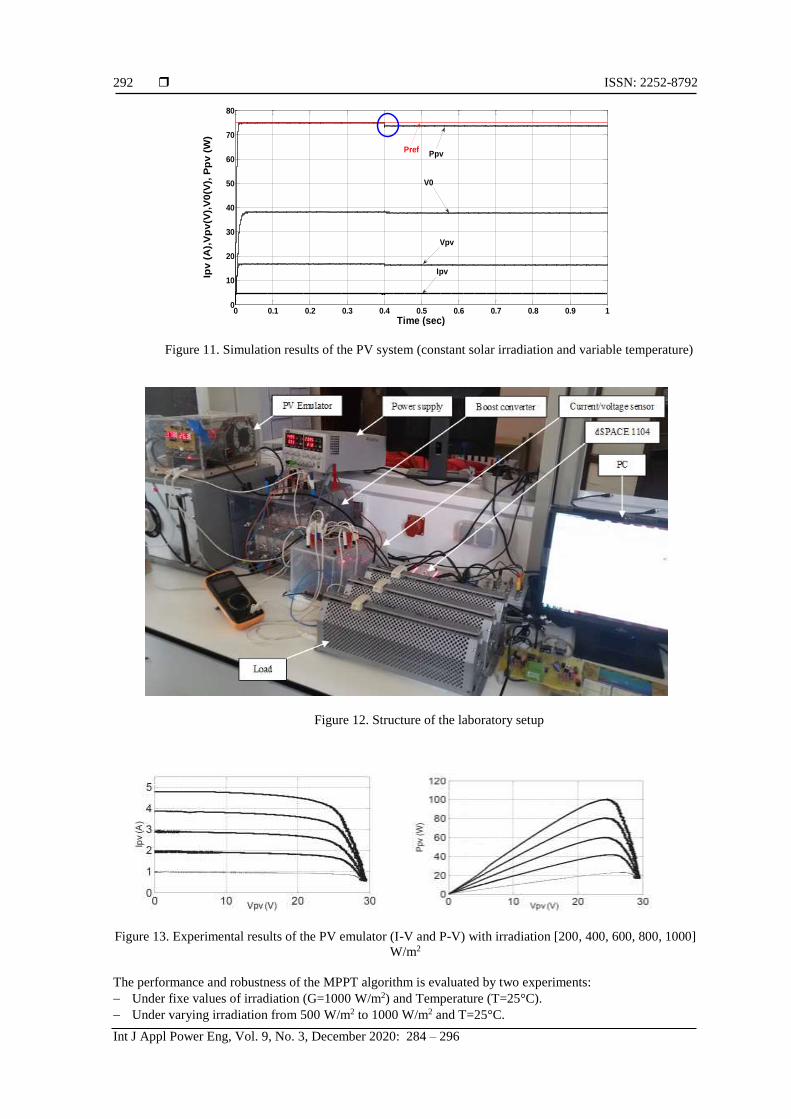
Figure 11 shows the tracking results with step temperature input from 25°C to 50°C at 0.4s, while
the irradiance is constant equal to 1000 W/m2 and load R=20Ω. The controller reaches steady state of both
temperature levels within small time transit response.
3.4. Experimental results
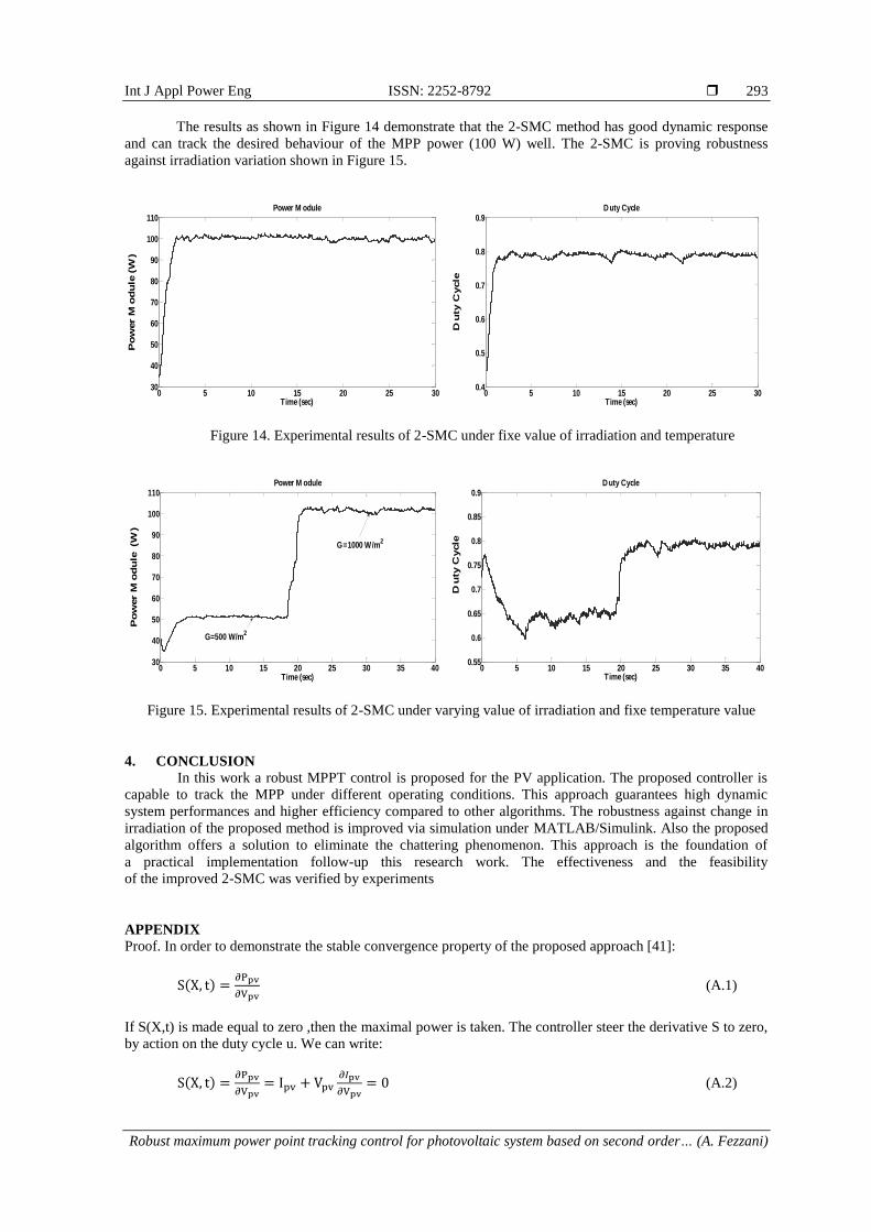
The basic structure of the laboratory setup (LSP-IE laboratory, University of Batna 2) is illustrated
in Figure 12. The Resistance is used as a load. The emulator connected with a boost converter has been used
instead of the module. The dSPACE DS1104 PPC is plugged in the host PC. The sensors used for
the currents and voltages measure are respectively LA-25NP and LV-25P. The MPPT control law
has been implemented in a dSPACE DS1104 R&D controller board. Then the PWM unit directly generates
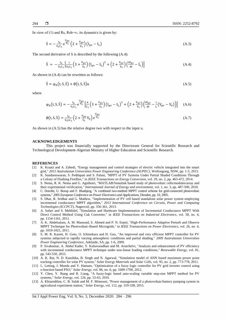
a 25 KHz PWM signal to control IGBT switch of the boost converter. The experimental characteristics of
the photovoltaic emulator are shown in Figure 13.
0 2 4 6 8 10 12 14 16 18 20 220
1
2
3
4
5
X: 17.09
Y: 4.387
Vpv(V)
Ipv
(A
)
0 2 4 6 8 10 12 14 16 18 20 220
20
40
60
80X: 17.09
Y: 75
Pp
v (
W)
Vpv(V)
MPP
MPP
0 0.005 0.01 0.015 0.02 0.025 0.03 0.035 0.04 0.045 0.050
20
40
60
80
Time (sec)
Pp
v (
W)
0 0.005 0.01 0.015 0.02 0.025 0.03 0.035 0.04 0.045 0.050
0.2
0.4
0.6
Time (sec)
Du
ty c
yc
le
Ref
1-SMC-MPPT
2-SMC-MPPT
ISSN: 2252-8792
Int J Appl Power Eng, Vol. 9, No. 3, December 2020: 284 – 296
292
Figure 11. Simulation results of the PV system (constant solar irradiation and variable temperature)
Figure 12. Structure of the laboratory setup
Figure 13. Experimental results of the PV emulator (I-V and P-V) with irradiation [200, 400, 600, 800, 1000]
W/m2
The performance and robustness of the MPPT algorithm is evaluated by two experiments:
Under fixe values of irradiation (G=1000 W/m2) and Temperature (T=25°C).
Under varying irradiation from 500 W/m2 to 1000 W/m2 and T=25°C.
0 0.1 0.2 0.3 0.4 0.5 0.6 0.7 0.8 0.9 10
10
20
30
40
50
60
70
80
Time (sec)
Ipv
(A
),V
pv
(V),
V0
(V),
Pp
v (
W)
PpvPref
Vpv
Ipv
V0
Int J Appl Power Eng ISSN: 2252-8792
Robust maximum power point tracking control for photovoltaic system based on second order… (A. Fezzani)
293
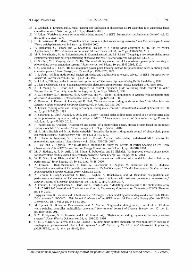
The results as shown in Figure 14 demonstrate that the 2-SMC method has good dynamic response
and can track the desired behaviour of the MPP power (100 W) well. The 2-SMC is proving robustness
against irradiation variation shown in Figure 15.
Figure 14. Experimental results of 2-SMC under fixe value of irradiation and temperature
Figure 15. Experimental results of 2-SMC under varying value of irradiation and fixe temperature value
4. CONCLUSION
In this work a robust MPPT control is proposed for the PV application. The proposed controller is
capable to track the MPP under different operating conditions. This approach guarantees high dynamic
system performances and higher efficiency compared to other algorithms. The robustness against change in
irradiation of the proposed method is improved via simulation under MATLAB/Simulink. Also the proposed
algorithm offers a solution to eliminate the chattering phenomenon. This approach is the foundation of
a practical implementation follow-up this research work. The effectiveness and the feasibility
of the improved 2-SMC was verified by experiments
APPENDIX
Proof. In order to demonstrate the stable convergence property of the proposed approach [41]:
S(X, t) =∂Ppv
∂Vpv (A.1)
If S(X,t) is made equal to zero ,then the maximal power is taken. The controller steer the derivative S to zero,
by action on the duty cycle u. We can write:
S(X, t) =∂Ppv
∂Vpv= Ipv + Vpv
∂𝐼pv
∂Vpv= 0 (A.2)
0 5 10 15 20 25 3030
40
50
60
70
80
90
100
110Power M odule
Time (sec)
Po
wer M
od
ule
(W
)
0 5 10 15 20 25 300.4
0.5
0.6
0.7
0.8
0.9D uty Cycle
Time (sec)
Du
ty C
ycle
0 5 10 15 20 25 30 35 4030
40
50
60
70
80
90
100
110Power M odule
Time (sec)
Po
wer M
od
ule
(W
)
G=1000 W/m2
G=500 W/m2
0 5 10 15 20 25 30 35 400.55
0.6
0.65
0.7
0.75
0.8
0.85
0.9D uty Cycle
Time (sec)
Du
ty C
ycle
ISSN: 2252-8792
Int J Appl Power Eng, Vol. 9, No. 3, December 2020: 284 – 296
294
In view of (1) and Rs, Rsh=∞, its dynamics is given by:
S = −I0
VtC1eVpvVt (2 +
Vpv
Vt) (Ipv − IL) (A.3)
The second derivative of S is described by the following (A.4):
S = −I0
VtC1[
1
VtC1(3 +
Vpv
Vt) (Ipv − IL)
2+ (2 +
Vpv
Vt) (
dIpv
dt− IL)] (A.4)
As shown in (A.4) can be rewritten as follows:
S = φA(t, S, S) + ∅(t, S, S)u (A.5)
where
φA(t, S, S) = −I0
VtC1eVpvVt [
A
C1(3 +
Vpv
Vt) (Ipv − IL)
2+ (2 +
Vpv
Vt) (
dIpv
dt−
1
L(Vpv − V0))] (A.6)
∅(t, S, S) =I0
VtLC1(2 +
Vpv
VtV0) e
Vpv
Vt (A.7)
As shown in (A.5) has the relative degree two with respect to the input u.
ACKNOWLEDGEMENTS This project was financially supported by the Directorate General for Scientific Research and
Technological Development-Algerian Ministry of Higher Education and Scientific Research.
REFERENCES [1] K. Kraatz and A. Zahedi, "Energy management and control strategies of electric vehicle integrated into the smart
grid," 2015 Australasian Universities Power Engineering Conference (AUPEC), Wollongong, NSW, pp. 1-5, 2015.
[2] K. Sundareswaran, S. Peddapati and S. Palani, "MPPT of PV Systems Under Partial Shaded Conditions Through
a Colony of Flashing Fireflies," in IEEE Transactions on Energy Conversion, vol. 29, no. 2, pp. 463-472, 2014.
[3] S. Nema, R. K. Nema and G. Agnihotri, "MATLAB/Simulink based study of photovoltaic cells/modules/array and
their experimental verification," International Journal of Energy and environment, vol. 1, no. 3, pp. 487-500, 2010.
[4] C. Dorofte, U. Borup and F. Blaabjerg, "A combined two-method MPPT control scheme for grid-connected photovoltaic
systems," 2005 European Conference on Power Electronics and Applications, Dresden, pp. 10, 2005.
[5] S. Dhar, R. Sridhar and G. Mathew, "Implementation of PV cell based standalone solar power system employing
incremental conductance MPPT algorithm," 2013 International Conference on Circuits, Power and Computing
Technologies (ICCPCT), Nagercoil, pp. 356-361, 2013.
[6] A. Safari and S. Mekhilef, "Simulation and Hardware Implementation of Incremental Conductance MPPT With
Direct Control Method Using Cuk Converter," in IEEE Transactions on Industrial Electronics, vol. 58, no. 4,
pp. 1154-1161, 2011.
[7] A. K. Abdelsalam, A. M. Massoud, S. Ahmed and P. N. Enjeti, "High-Performance Adaptive Perturb and Observe
MPPT Technique for Photovoltaic-Based Microgrids," in IEEE Transactions on Power Electronics, vol. 26, no. 4,
pp. 1010-1021, 2011.
[8] S. M. R. Kazmi, H. Goto, O. Ichinokura and H. Guo, "An improved and very efficient MPPT controller for PV
systems subjected to rapidly varying atmospheric conditions and partial shading," 2009 Australasian Universities
Power Engineering Conference, Adelaide, SA, pp. 1-6, 2009.
[9] P. Sivakumar, A. Abdul Kader, Y. Kaliavaradhan and M. Arutchelvi, "Analysis and enhancement of PV efficiency
with incremental conductance MPPT technique under non-linear loading conditions," Renewable Energy, vol. 81,
pp. 543-550, 2015.
[10] A. K. Rai, N. D. Kaushika, B. Singh and N. Agarwal, "Simulation model of ANN based maximum power point
tracking controller for solar PV system," Solar Energy Materials and Solar Cells, vol. 95, no. 2, pp. 773-778, 2011.
[11] L. Letting, J. Munda and Y. Hamam, "Optimization of a fuzzy logic controller for PV grid inverter control using
s-function based PSO," Solar Energy, vol. 86, no. 6, pp. 1689-1700, 2012.
[12] Y. Chen, Y. Jhang and R. Liang, "A fuzzy-logic based auto-scaling variable step-size MPPT method for PV
systems," Solar Energy, vol. 126, pp. 53-63, 2016.
[13] A. Khiareddine, C. B. Salah and M. F. Mimouni, "Power management of a photovoltaic/battery pumping system in
agricultural experiment station," Solar Energy, vol. 112, pp. 319-338, 2015.
Int J Appl Power Eng ISSN: 2252-8792
Robust maximum power point tracking control for photovoltaic system based on second order… (A. Fezzani)
295
[14] Y. Gheddadi, F. Errahimi and E. Najia, "Desiyn and verification of photovoltaic MPPT algorithm as an automotive-based
embedded sofware," Solar Energy, vol. 171, pp. 414-425, 2018.
[15] V. Utkin, "Variable structure systems with sliding modes," in IEEE Transactions on Automatic Control, vol. 22,
no. 2, pp. 212-222, 1977.
[16] H. De Battista and R. J. Mantz, "Variable structure control of a photovoltaic energy converter," in IEE Proceedings - Control
Theory and Applications, vol. 149, no. 4, pp. 303-310, 2002.
[17] E. Mamarelis, G. Petrone and G. Spagnuolo, "Design of a Sliding-Mode-Controlled SEPIC for PV MPPT
Applications," in IEEE Transactions on Industrial Electronics, vol. 61, no. 7, pp. 3387-3398, 2014.
[18] M. R. Mojallizadeh, M. A. Badamchizadeh, S. Khanmohammadi and M. Sabahi, "Designing a new robust sliding mode
controller for maximum power point tracking of photovoltaic cells," Solar Energy, vol. 132, pp. 538-546, 2016.
[19] C. S. Chiu, Y. L. Ouyang, and C. Y. Ku, "Terminal sliding mode control for maximum power point tracking of
photovoltaic power generation systems," Solar energy, vol. 86, no. 10, pp. 2986-2995, 2012.
[20] C-C. Chu and C-L. Chen, "Robust maximum power point tracking method for photovoltaic cells: A sliding mode
control approach," Solar Energy, vol. 83, no. 8, pp. 1370-1378, 2009.
[21] V. I. Utkin, "Sliding mode control design principles and applications to electric drives," in IEEE Transactions on
Industrial Electronics, vol. 40, no. 1, pp. 23-36, 1993.
[22] V. I. Utkin, "Sliding modes in control and optimization," Germany: Springer-Verlag Berlin Heidelberg, 1992.
[23] I. Utkin, J. Gulder and J. Shi, "Sliding mode control in electromechanical systems," United Kingdom: CRC Press, 1999.
[24] K. D. Young, V. I. Utkin and U. Ozguner, "A control engineer's guide to sliding mode control," in IEEE
Transactions on Control Systems Technology, vol. 7, no. 3, pp. 328-342, 1999.
[25] A. G. Bondarev, S. A. Bondarev, N. E. Kostyleva, and V. I. Utkin, "Sliding modes in systems with asymptotic state
observers," Automatika I Telemekhanika, vol. 46, no. 6, pp. 679-684, 1985.
[26] G. Bartolini, A. Ferrara, A. Levant, and E. Usai, "On second order sliding mode controllers," Variable Structure
Systems, Sliding Mode and Nonlinear Control, vol. 247, pp. 329-350, 2007.
[27] A. Levant, "Sliding order and sliding accuracy in sliding mode control," International Journal of Control, vol. 58,
no. 6, pp. 1247-1263, 1993.
[28] H. Saharaoui, L. Chrifi-Alaouil, S. Drid, and P. Bussy, "Second order sliding mode control of dc-dc converter used
in the photovoltaic system according an adaptive MPPT," International Journal of Renewable Energy Research,
vol. 6, no. 2, pp. 475-383, 2016.
[29] H. Yatimi and E. Aroudam, "Assessment and control of a photovoltaic energy storage system based on the robust
sliding mode MPPT controller," Solar Energy, vol. 139, pp. 557-568, 2016.
[30] M. R. Mojallizadeh and M. A. Badamchizadeh, "Second-order fuzzy sliding-mode control of photovoltaic power
generation systems," Solar Energy, vol. 149, pp. 332-340, 2017.
[31] A. Kchaou, A. Naamane, Y. Koubaa, and N. M’sirdi, "Second order sliding mode-based MPPT control for
photovoltaic applications," Solar Energy, vol. 155,pp. 758-769, 2017.
[32] H. Patel and V. Agarwal, "MATLAB-Based Modeling to Study the Effects of Partial Shading on PV Array
Characteristics," in IEEE Transactions on Energy Conversion, vol. 23, no. 1, pp. 302-310, 2008.
[33] M. U. Siddiqui, A. F. M. Arif, A. M. Bilton, S. Dubowsky, and M. Elshafei, "An improved electric circuit model
for photovoltaic modules based on sensitivity analysis," Solar Energy, vol. 90, pp. 29-42, 2013.
[34] W. D. Soto, S. A. Klein, and W. A. Beckam, "Improvement and validation of a model for photovoltaic array
performance," Solar Energy, vol. 80, no. 1, pp. 78-88, 2006.
[35] A. Fezzani, I. Hadj-Mahammed, S. Drid, A. Bouchakour, L. Zaghba, M. Benbitour and H. S. Oudjana,
"Degradation evaluation of PV module using solmetric PVA-600 analyzer,” The 4th International Seminar on New
and Renewable Energies (SIENR’2016), Ghardaïa, 2016.
[36] A. Fezzani, I. Hadj-Mahammed, S. Drid, L. Zaghba, A. Bouchakour, and M. Benbitour, "Degradation and
performance evaluation of PV module in desert climate conditions with estimate uncertainty in measuring,”
Serbian Journal of Electrical Engineering, vol. 14, no. 2, pp. 277-299, 2017.
[37] A. Fezzani, I. Hadj-Mahammed, S. Drid, and L. Chrifi-Alaoui, "Modelling and analysis of the photovoltaic array
faults,” 2015 3rd International Conference on Control, Engineering & Information Technology (CEIT), Tlemcen,
pp. 1-9, 2015.
[38] Jingquan Chen, R. Erickson and D. Maksimovic, "Averaged switch modeling of boundary conduction mode DC-to-
DC converters," IECON'01. 27th Annual Conference of the IEEE Industrial Electronics Society (Cat. No.37243),
Denver, CO, USA, vol. 2, pp. 844-849, 2001.
[39] M. Djemai, K. Bosawon, Benmonsour, and A. Marouf, "High-order sliding mode control of a DC drive
via a switched controller multicellular converter," International Journal of Systems Science, vol. 42, no. 11,
pp. 1869-1888, 2011.
[40] S. V. Emelyanov, S. K. Korovin, and L. V. Levantovsky, "Higher order sliding regimes in the binary control
systems," Soviet Physics Doklady, vol .31, pp. 291-293, 1986.
[41] O. E. L. Maguiri, A. Farchi, and E. M. Louragli, "Sliding mode control approach for maximum power tracking in
single-phase grid-connected photovoltaic systems," IOSR Journal of Electrical And Electronics Engineering
(IOSR-JEEE), vol. 9, no. 4, pp. 41-49, 2014.

ISSN: 2252-8792
Int J Appl Power Eng, Vol. 9, No. 3, December 2020: 284 – 296
296
BIOGRAPHIES OF AUTHORS
Amor Fezzani was born in Batna (Algeria), on September 9, 1971. He graduated from the El
Hadj Lakhda. University (Algeria) in 1996 with electrical engineering degree. He received M.Sc.
and Ph.D degrees in electrical engineering, from the University of Batna, Algeria, respectively in
2009 and 2015. Currently, he is researcher at the Unité de Recherche Appliquée en Energies
Renouvelables, URAER, Centre de Développement des Energies Renouvelables, CDER,
Alegria. His research interests concern: renewable energy, power electronics, electric machines,
robust control, etc.
Noureddine Bouarroudj was born in Cheria, Tebessa, Algeria, in 1983. He received his degree
in Automatic control from the University of Tebessa, Algeria, in 2008 and his MSc, and Ph.D
degrees in electrical engineering (automatic option) from Ecole Nationale Polytechnique (ENP),
Algeria, respectively in 2011, and 2017. He is currently a Researcher in Unité de Recherche
Appliquée en Energies Renouvelables/CDER, Ghardaia, Algeria. His research interests include
fractional-order control, sliding mode control, renewable energy systems and their controls and
control optimisation.
Said Drid was born in Batna, Algeria, in 1969. He received B.Sc., M.Sc. and PhD degrees in
electrical engineering, from the University of Batna, Algeria, respectively in 1994, 2000 and
2005. Currently, he is full professor at the Electrical Engineering Institute at University of Batna,
Algeria. He is the head of the “Energy Saving and Renewable Energy” team in the Research
Laboratory of Electromagnetic Induction and Propulsion Systems of Batna University. He is
currently the vice chair of the PES chapter, IEEE Algeria subsection. His research interests include
electric machines and drives, renewable energy, field theory and computational electromagnetism.
Layachi Zaghba received his diploma degree in Automatic Engineering in 2002 and his MSc
degree in electronics in 2005 from the Science and Technology, Department of Jijel University.
He received his PhD degree in electrical engineering (automatic) from the University of Biskra,
Algeria, in 2017. Now, He is a researcher at the Unit for Applied Research in Renewable Energy
(URAER), Ghardaia, Algeria. His main interest areas are the photovoltaic systems and their
applications, control, optimization, performance analysis of grid connected photovoltaic.