Embed Size (px)
Citation preview
0
Ravi Margasahayam1
ROCKET LAUNCH TRAJECTORY
SIMULATION MECHANISM
Ravi Margasahayam
Dynacs Inc.
John F. Kennedy Space Center, FL, USA
Raoul E. Caimi and Sharon Hauss
National Aeronautics and Space Administration (NASA)
John F. Kennedy Space Center, FL, USA
E-mail address: Ravi. Margasahayam-1 @ksc.nasa.gov
Abstract
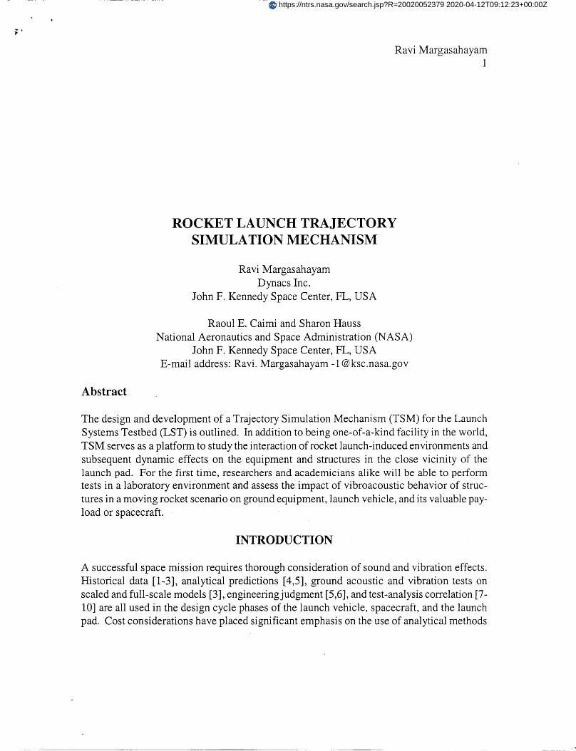
The design and development of a Trajectory Simulation Mechanism (TSM) for the Launch
Systems Testbed (LST) is outlined. In addition to being one-of-a-kind facility in the world,
TSM serves as a platform to study the interaction of rocket launch-induced environments and
subsequent dynamic effects on the equipment and structures in the close vicinity of the
launch pad. For the first time, researchers and academicians alike will be able to perform
tests in a laboratory environment and assess the impact of vibroacoustic behavior of struc-
tures in a moving rocket scenario on ground equipment, launch vehicle, and its valuable pay-
load or spacecraft:
INTRODUCTION
A successful space mission requires thorough consideration of sound and vibration effects.
Historical data [1-3], analytical predictions [4,5], ground acoustic and vibration tests on
scaled and full-scale models [3], engineering judgment [5,6], and test-analysis correlation [7-
10] are all used in the design cycle phases of the launch vehicle, spacecraft, and the launch
pad. Cost considerations have placed significant emphasis on the use of analytical methods
https://ntrs.nasa.gov/search.jsp?R=20020052379 2020-04-12T09:12:23+00:00Z
e
Ravi Margasahayam2
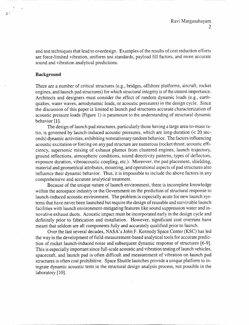
and test techniques that lead to overdesign. Examples of the results of cost reduction efforts
are force-limited vibration, uniform test standards, payload fill factors, and more accurate
sound and vibration analytical predictions.
Background
There are a number of critical structures (e.g., bridges, offshore platforms, aircraft, rocket
engines, and launch pad structures) for which structural integrity is of the utmost importance.
Architects and designers must consider the effect of random dynamic loads (e.g., earth-
quakes, water waves, aerodynamic loads, or acoustic pressures) in the design cycle. Since
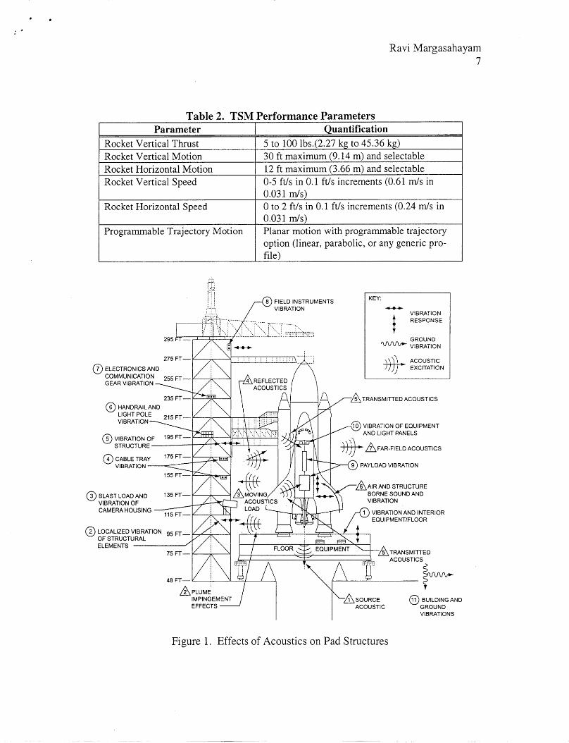
the discussion of this paper is limited to launch pad structures accurate characterization of
acoustic pressure loads (Figure 1) is paramount to the understanding of structural dynamic
behavior [1 ].
The design of launch pad structures, particularly those having a large area-to-mass ra-
tio, is governed by launch-induced acoustic pressures, which are long-duration (< 20 sec-
onds) dynamic activities, exhibiting nonstationary random behavior. The factors influencing
acoustic excitation or forcing on any pad structure are numerous (rocket thrust, acoustic effi-
ciency, supersonic mixing of exhaust plumes from clustered engines, launch trajectory,
ground reflections, atmospheric conditions, sound directivity patterns, types of deflectors,
exposure duration, vibroacoustic coupling, etc.). Moreover, the pad placement, shielding,
material and geometrical attributes, mounting, and operational aspects of pad structures also
influence their dynamic behavior. Thus, it is impossible to include the above factors in any
comprehensive and accurate analytical treatment.
Because of the unique nature of launch environment, there is incomplete knowledge
within the aerospace industry or the Government on the prediction of structural response to
launch-induced acoustic environment. The problem is especially acute for new launch sys-
tems that have never been launched but require the design of reusable and survivable launch
facilities with launch environment-mitigating features like sound suppression water and in-
novative exhaust ducts. Acoustic impact must be incorporated early in the design cycle and
definitely prior to fabrication and installation. However, significant cost overruns have
meant that seldom are all components fully and accurately qualified prior to launch.
Over the last several decades, NASA's John F. Kennedy Space Center (KSC) has led
the way in the development of field-measurement-based analytical tools for accurate predic-
tion of rocket launch-induced noise and subsequent dynamic response of structures [6-9].
This is especially important since full-scale acoustic and vibration testing of launch vehicles,
spacecraft, and launch pad is often difficult and measurement of vibration on launch pad
structures is often cost prohibitive. Space Shuttle launches provide a unique platform to in-
tegrate dynamic acoustic tests in the structural design analysis process, not possible in the
laboratory [10].
RaviMargasahayam3
LAUNCH SYSTEMS TESTBED
NASA has designated KSC as the Center for Excellence for launch and payload processing
systems. Under this mandate, KSC is required to address four important goals: (1) ensure
sound, safe, and efficient vibroacoustic techniques are in place for private/commercial proc-
essing; (2) increase the operational knowledge in the design/development of payloads and
new vehicles; (3) partner to develop new technologies for future space initiatives; and (4)
continually increase core capabilities to meet varying customer needs and demands.
The newly implemented LST is an avenue through which KSC will accomplish the
above goals. LST's overall mission is to reduce costs and increase safety, reliability, and
availability of launch structures and mechanisms exposed to rocket launch environments.
Brief aspects of design and infrastructure development of the Rocket Launch Trajectory
Simulation Mechanism (TSM), key LST components, are the focus of this paper.
LST projects will focus on the following technical areas:
• Predict, measure, and validate acoustic excitation models
• Enhance structural vibration response methods
• Develop and evaluate acoustic suppression systems
• Analyze exhaust plume using computational fluid dynamics
• Optimize exhaust duct configurations for new vehicles
• Institute rocket noise and vibration scaling methodologies
The current LST capabilities include:
• Specialized personnel with acoustics, structural dynamics, test, launch environment
data analysis, and computational fluid dynamics experience
• A unique launch environment (acoustics, vibration, strain, etc.) database for over
100 launches (serving as a knowledge reservoir)
• Launch environments prediction and structural analysis methodologies to assess
nonstationary random data
• A unique, small-scale rocket liftoff test facility to simulate moving rocket scenar-
ios required in the real world
One key objective of LST is to simulate small-scale launch environments for use in
testing and evaluation of launch pad designs for future space vehicles for NASA. The end
result is to arrive at launch,induced acoustic excitation models that yield more realistic struc-
tural vibration response estimates than those provided by the methods currently available.
TRAJECTORY SIMULATION MECHANISM
At KSC, significant effort was undertaken to measure acoustic loads and vibration response
under the Verification Test Article (VETA) project. VETA proved to be a structural dyna-
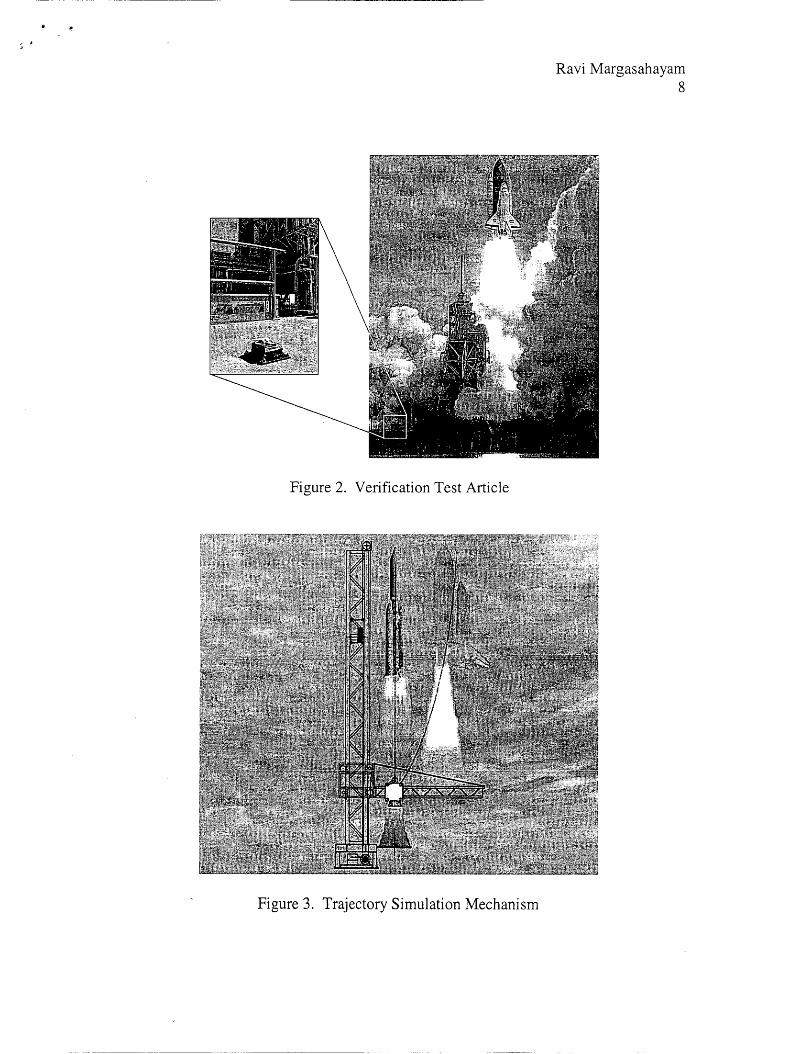
mist's dream come true. The premise behind VETA testing [ 10] was if acoustic loads cannot
be generated in the lab; take the entire testing operation to the field (Figure 2). This totally
Ravi Margasahayam4
eliminatedtheambiguityof simulatingthelaunchenvironment.Despitethis,VETA seriesof testspavedtheway for validatingthevibrationresponsemethodologydevelopedoveradecadeat KSC [7-9].
As outlinedearlier,launch-inducedacousticexcitationis anonstationaryandrandomandexhibitsnon-Gaussianbehavior.Unlikevehiclesandpayloads,launchsupportstructurescannotbe testedandverifiedprior to launch.Fully valid acousticloadscanonly begener-atedby thelaunchof a full-scalevehiclein thestrictestsense.Laboratoryacoustictestscomecloseto applyingveryhighacousticloads.However,theselackthetruesimulationofthedynamicnatureof thelaunchenvironment.Evenalimited simulationof nonstationaryrandomenvironmentdisplayingcharacteristicsof trueacousticshasbeenlacking to date.
A surveyof the literatureonsmall-scaletestingof rocketsdidnotrevealanypasteffortto simulateatestfacility thatcouldhandleamovingrocketscenarioto assesstheimpactoflaunch-inducedenvironmentsongroundequipmentandstructureswithin thevicinity of thelaunchpad.Most studieshavereliedonstaticfiring of scaledor full-scaleengines.Someoftheearlytestsincludedhorizontalfirings,yetsomeotherresearchershaveattemptedtotakeacousticdataby movingtherocketnozzleverticallyor horizontallyin astepwisemanner.Thesestaticor quasi-statictestsdonotsimulatethelaunchenvironmentin atruesense.
Lessonslearnedfrom literaturesurvey,enhancementsto othertestfacilities,andtheexperiencefromVETA werecarefullyincorporatedin thedevelopmentstageof TSM. Onedrawbackof VETA testingwasthetimefactor. To collectstatisticallysignificantdatane-cessitatedyearsof testing.Designanddevelopmentof TSMcapabilityaddressedtheprob-lemof acquiringacousticalandvibrationdatafrom multiplelaunchesinashorttime. More-over,theTSMisusedtogenerateanonstationary,scaledacousticload. Ourprimarygoalinthedesignanddevelopmentof theTSMwasto eliminatethemostimportantdrawback- theability to simulatethe launchtrajectoryin a dynamicsense,hithertonot attemptedby re-searchers.Thus,it wasplannedto designandconstructatestfacility thatiscapableof beingconfiguredto scaledlaunchenvironmentsof futurevehicles. Thescaledlaunchenviron-mentswill beusedto predictthefull-scalelaunchenvironments.
Performance Parameters
TSM is a one-of-a-kind, scaled, moving, single/multiple, combusting, and noncombusting
supersonic jet plume test and research laboratory. TSM is capable of simulating varied
launch trajectories while inducing nonstationary random acoustic loads on pad structures
similar to those generated by the launch of a rocket. LST projects will focus on vibroacous-
tics, acoustic suppression systems exhaust plume flow modeling, exhaust duct optimization,
scaling methods, assessment of composite structures, fatigue life prediction, hydrogen en-
trapment, and related areas.
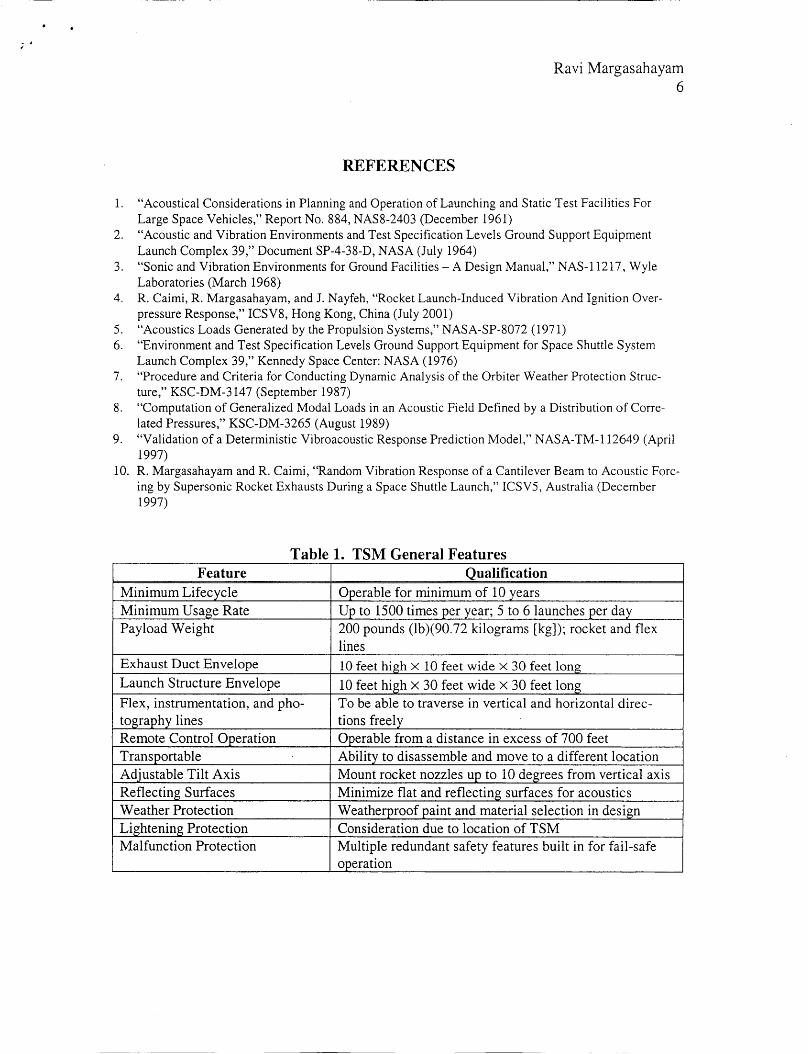
Table 1 outlines the general requirements that were developed prior to the design of
TSM. The overall project plan, encompassing cold jet tests followed by hot and combusting
RaviMargasahayam5
jets,primarily drovetherequirements.Issuespertainingtotheuseof liquid andsolid fuelsandtheir impacton theTSM wereconsidered.Basedon theseneeds,theoperablelife ofTSMwasdeterminedto bearound10years.Thisis alleviatedbyTSM's usagerateof 1500rocketlaunchesperyear,comparedto theSpaceShuttle'srateof 7 to 8 launchesperyear.
Thedesignanddevelopmentof TSM capabilitieswerelargelybasedonU.S. launchindustryrequirements.Table2 documentsperformancerequirementsof theTSM. TheSpaceShuttlewill mostlikely bethemainstayof NASA's avenuefor theimmediatefuture.TheInternationalSpaceStation(ISS)goalsandobjectivesdrivethisuse.Therefore,it wasdecidedto scaleverticalandhorizontaltravelbasedontheSpaceShuttlelaunchscenario.Inaddition,requirementsfor TSMverticalspeedsandhorizontalspeedsweredrivenbySpaceShuttletrajectory. Thetravel speedscanbepreciselycontrolledin fractionalincrements.Thus,basedon theabove;theTSM wasdesignedtobea1/10-scalemodel.Literaturereviewidentifiedscalemodelsthatrangefrom 1/5to 1/12scale.Optimalvaluesfor thescaledtestfacilities arein the 1/7-to-i/10range.
TSMfeaturesaplanarmotioncapabilitywithprogrammabletrajectory.In anutshell,itis giantX-Y tablemountedvertically(Figure3). In additionto thesimulationoflinear (ver-tical) trajectory,anyparabolic(similartoShuttle)orothergenericprofilecanbeincorporatedin thetestsequence.Thiswasdeemednecessarytosupporttheliftoff sequenceof Delta,Ti-tan,Atlas,andanyotherU.S.rockets.TSMwill permitthesimulation(increaseor decrease)of liftoff ratesandhandleanydrift duringthe ascentstagesof therocketasthetower iscleared.TSMcanalsohandlenozzletilt requirements.Besidesprovidingthecapabilitytooperateremotelyfrom over200meters,carewastakento minimizeflat reflectingsurfacesandincludeweatherprotectionfeaturesfor outdooruse.
CONCLUSIONS
A test capability to simulate rocket launch trajectories and to generate nonstationary, scaled
acoustic loads is presented.. TSM, for the first time, will enable researchers to study the dy-
namic effects of acoustic loads accurately and help them to assess the vibration responses
generated by the launch of rockets on pad equipment and structures. Impact of launch-
induced acoustic noise and its influence on the design of ground support equipment is vital to
mission success. Immediate LST research will focus on reducing acoustic environments at
the payload, vehicle, and ground systems, to develop new launch exhaust management sys-
tems. LST therefore represents a leap in technological innovation in the area of vibroacous-
tic research and development, hitherto not available to architects, engineers and designers of
rocket launch systems.
d,
Ravi Margasahayam
6
REFERENCES
1. "Acoustical Considerations in Planning and Operation of Launching and Static Test Facilities For
Large Space Vehicles," Report No. 884, NAS8-2403 (December 1961)
2. "Acoustic and Vibration Environments and Test Specification Levels Ground Support Equipment
Launch Complex 39," Document SP-4-38-D, NASA (July 1964)
3. "Sonic and Vibration Environments for Ground Facilities - A Design Manual," NAS-11217, WyleLaboratories (March 1968)
4. R. Caimi, R. Margasahayam, and J. Nayfeh, "Rocket Launch-Induced Vibration And Ignition Over-
pressure Response," ICSV8, Hong Kong, China (July 2001)
5. "Acoustics Loads Generated by the Propulsion Systems," NASA-SP-8072 (1971)
6. "Environment and Test Specification Levels Ground Support Equipment for Space Shuttle SystemLaunch Complex 39," Kennedy Space Center: NASA (1976)
7. "Procedure and Criteria for Conducting Dynamic Analysis of the Orbiter Weather Protection Struc-
ture," KSC-DM-3147 (September 1987)
8. "Computation of Generalized Modal Loads in an Acoustic Field Defined by a Distribution of Corre-lated Pressures," KSC-DM-3265 (August 1989)
9. "Validation of a Deterministic Vibroacoustic Response Prediction Model," NASA-TM-112649 (April
1997)
10. R. Margasahayam and R. Caimi, "Random Vibration Response of a Cantilever Beam to Acoustic Forc-
ing by Supersonic Rocket Exhausts During a Space Shuttle Launch," ICSVS, Australia (December1997)
Table 1. TSM General Features
Feature Qualification
Minimum Lifecycle
Minimum Usage Rate
Payload Weight
Exhaust Duct Envelope
Launch Structure Envelope
Flex, instrumentation, and pho-
tography lines
Remote Control Operation
Transportable
Adjustable Tilt Axis
Reflecting SurfacesWeather Protection
Lightening ProtectionMalfunction Protection
Operable for minimum of 10 years
Up to 1500 times per year; 5 to 6 launches per day
200 pounds (lb)(90.72 kilograms [kg]); rocket and flex
lines
10 feet high × 10 feet wide × 30 feet long
10 feet high x 30 feet wide × 30 feet longTo be able to traverse in vertical and horizontal direc-
tions freely
Operable from a distance in excess of 700 feet
Ability to disassemble and move to a different location
Mount rocket nozzles up to 10 degrees from vertical axis
Minimize fiat and reflecting surfaces for acoustics
Weatherproof paint and material selection in designConsideration due to location of TSM
Multiple redundant safety features built in for fail-safe
operation
Ravi Margasahayam
7
Table 2. TSM Performance Parameters
Parameter Quantification
Rocket Vertical Thrust 5 to 100 lbs.(2.27 kg to 45.36 kg)30 ft maximum (9.14 m) and selectableRocket Vertical Motion
Rocket Horizontal Motion 12 ft maximum (3.66 m) and selectable
Rocket Vertical Speed 0-5 ft/s in 0.1 ft/s increments (0.61 m/s in0.031 rn/s)
Rocket Horizontal Speed 0 to 2 ft/s in 0.1 ft/s increments (0.24 m/s in
0.031 m/s)
Programmable Trajectory Motion Planar motion with programmable trajectory
option (linear, parabolic, or any generic pro-file)
KEY:
VIBRATION
RESPONSE
GROUNDVIBRATION
@ ACOUSTICEXCITATION
TRANSMITTED ACOUSTICS
VIBRATION OF EQUIPMENT
AND LIGHT PANELS
@ ,/_ FAR-FIELD ACOUSTICS
PAYLOAD VIBRATION
AIR AND STRUCTURE
BORNE SOUND ANDVIBRATION
VIBRATION AND INTERIOREQUIPMENT/FLOOR
SOURCEACOUSTIC
TRANSMITTED
ACOUSTICS
BUILDING ANDGROUND
VIBRATIONS
Figure 1. Effects of Acoustics on Pad Structures
Ravi Margasahayam8
Figure 2. Verification Test Article
Figure 3. Trajectory Simulation Mechanism