Embed Size (px)
Citation preview
EE C245 – ME C218 Fall 2003 Lecture 6
EE C245 - ME C218Introduction to MEMS Design
Fall 2003
Roger Howe and Thara SrinivasanLecture 6 Mechanics of Materials
2EE C245 – ME C218 Fall 2003 Lecture 6
Today’s Lecture• Stress, strain, etc. � isotropic materials• Thin films: thermal stress, residual stress, and stress gradients,
internal dissipation• MEMS material properties and performance metrics
See also http://www.memsnet.org/material/
• Elastic constants for anisotropic materials (e.g. Si)
• Reading:Senturia, Chapter 8Yasumura, K. Y., et al, “Quality factors in micron- and submicron-thick
cantilevers,” Journal of Microelectromechanical Systems, 9, 2000, pp. 117-125.
Candler, R., et al, “Investigation of energy loss mechanisms in micromechanical resonators,” 12th Int. Conf. on Solid-StateSensors, Actuators, and Microsystems (Transducers ’03), Boston, Mass., June 8-12, 2003, pp. 360-363.

3EE C245 – ME C218 Fall 2003 Lecture 6
Normal Stress = Force per unit Area
A
FF
σ = F / A units = [N/m2] = Pa
What happens?
L
4EE C245 – ME C218 Fall 2003 Lecture 6
Strain = fractional change in length
FF
LL’
Define ε = (L’ – L)/L units: [ ]
Strain is found to be proportional to stress(for “small” stresses at “lower” temperatures):
ε = σ / E

5EE C245 – ME C218 Fall 2003 Lecture 6
Poisson’s Ratio
FxFx W’W
εy = (W’ – W) / W
εy = - ν εx ν = Poisson’s Ratio
6EE C245 – ME C218 Fall 2003 Lecture 6
Forces || to Surfaces � Shear Stress
F
FNote: compensating forces are appliedto the vertical faces to avoid a net torque!
θ
τ = F /A = shear stress G = shear modulus
A
θ = τ / G

7EE C245 – ME C218 Fall 2003 Lecture 6
Normal and Shear Componentsfor an Isotropic Solid
• Isotropic = same in all directions• Add in off-axis strains from normal stresses in other
directions
εx = (1/E)[σx- ν (σy + σz)]
Poisson strains from off x-axis stress
εy = (1/E)[σy- ν (σx + σz)]
εz = (1/E)[σz- ν (σx + σy)]
8EE C245 – ME C218 Fall 2003 Lecture 6
Important Special Case: Plane Stress• Common case: very thin film coating a thin, relatively
rigid substrate (e.g., a silicon wafer)
600 μm
Top surface is unstressed � σz = 0
z
εx = (1/E)[σx- ν (σy + 0)] εy = (1/E)[σy- ν (σx + 0)]
Symmetry in x-y plane � σx = σy = σ

9EE C245 – ME C218 Fall 2003 Lecture 6
Plane Stress Case (cont.)• In-plane strain components εx = εy = ε
ε = (1/E)[σ- νσ] = σ (1- ν )/E
• Bi-axial modulus
E’ = E / (1- ν )
10EE C245 – ME C218 Fall 2003 Lecture 6
Linear Thermal Expansion• As temperature increases, most solids expand in volume �
define the linear thermal expansion coefficient by
dTd x
Tεα =
• Why important?
Source of strain (due to mismatch between layers … thin film andsubstrate, substrate and package, package and board, etc.)
Can be exploited for thermal-expansion based actuators

11EE C245 – ME C218 Fall 2003 Lecture 6
Linear Thermal Expansion: Varies with Temperature
12EE C245 – ME C218 Fall 2003 Lecture 6
Thermal Stress• Assume film is deposited stress-free at a temperature Td
Si: αTs = 2.8 x 10⁻⁶ K-1
film: αTf
• At room temperature Tr , the film is under a thermal mismatch strain (a “built-in” strain) given by
)()( TT TfTsx Δ−−Δ−= ααε
13EE C245 – ME C218 Fall 2003 Lecture 6
Residual Stress in Thin Films• What is measured in a thin film
(e.g., by the induced substrate curvature) �define as the residual stress
• Thermal mismatch stress: well understood• What is not explained by thermal mismatch �
define as the intrinsic stress
• Origins of intrinsic stress: many and varied!
14EE C245 – ME C218 Fall 2003 Lecture 6
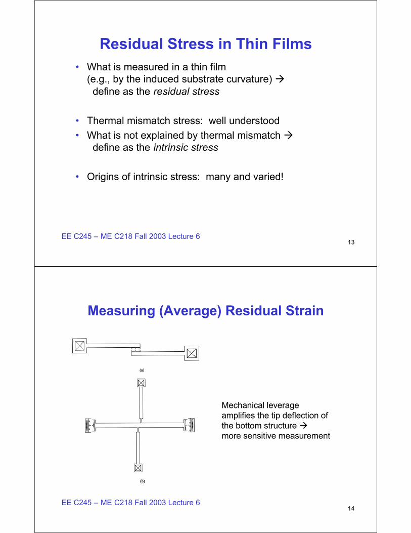
Measuring (Average) Residual Strain
• Mechanical leverage amplifies the tip deflection of the bottom structure �more sensitive measurement

15EE C245 – ME C218 Fall 2003 Lecture 6
As-Deposited Stress in LPCVD Poly-Si and Poly-SiGe Films at Tr
Y.-C. Jeon, T.-J. King, and R. T. Howe,J. Electrochemical Society, 150, H1-H6 (2003)
αT’sarematched!
αT’saren’tmatched –SiGe: 4.7Si: 2.8
16EE C245 – ME C218 Fall 2003 Lecture 6
Residual Stress in Poly-SiGe Alloys at Tr
Y.-C. Jeon, T.-J. King, and R. T. Howe,J. Electrochemical Society, 150, H1-H6 (2003)
Interpretation:

17EE C245 – ME C218 Fall 2003 Lecture 6
Annealed “Stress-Free” Poly-SiGe Films
Eliminatedintrinsic stress
18EE C245 – ME C218 Fall 2003 Lecture 6
Residual Strain GradientsIntrinsic strain can vary through the film thickness,resulting in warping of some structures
Extreme example:as-deposited poly-SiGe
Question:
Was this film tensile orcompressive?
Answer:
SEM: Carrie Low, BSAC

19EE C245 – ME C218 Fall 2003 Lecture 6
Understanding the Difference between Average Strain and Strain Gradient
• Case 1. Average strain > 0 (tensile); top of film is more tensile than bottom
• Case 2. Average strain < 0 (compressive); bottom of film is more compressive than top
20EE C245 – ME C218 Fall 2003 Lecture 6
Failure by Fracture (or Yielding)
(or Si at T > 900 oC)
(Si at T = 30 oC)

21EE C245 – ME C218 Fall 2003 Lecture 6
Internal Dissipation (Losses)• All materials dissipate energy when undergoing cyclic
vibrations• Origins (see papers by Yasumura and Candler)
1. Anharmonic (non-quadratric) interatomic forces2. Mobile defects, especially at grain boundaries3. Surface films (thin oxides) and adsorbed species4. Thermoelastic damping (vibrational modes with volume change)
x(t)
t
22EE C245 – ME C218 Fall 2003 Lecture 6
Example MEMS Material Properties
From Mark Spearing, MIT, Future of MEMSWorkshop, Cambridge, England, May 2003
Units:(m/s)2

23EE C245 – ME C218 Fall 2003 Lecture 6
Young’s Modulus – Density Plot
Ashby, Mechanics ofMaterials, Pergamon,1992.
24EE C245 – ME C218 Fall 2003 Lecture 6
Young’s Modulus and Useful Strength
From Mark Spearing, MIT, Future of MEMSWorkshop, Cambridge, England, May 2003
Stored mechanical energy

25EE C245 – ME C218 Fall 2003 Lecture 6
What is a Material’s Useful Strength?
• Yield or fracture stress … ultimate limits• Practical limit: tolerable deviation from linearity of
stress-strain curve• Example: silicon (100) direction
E = Eo(1 + E1ε + E2 ε2)
Eo = 130 GPa, E1 = 0.65, E2 = -4.6result: εmax ˜ 2 x 10⁻³ (roughly 1/5 of fracture limit)
V. Kaajakari (VTT, Helsinki, Finland),Transducers ’03, Boston, paper 3E102.P
26EE C245 – ME C218 Fall 2003 Lecture 6
Young’s Modulus vs. Strength
Ashby, Mechanics ofMaterials, Pergamon,1992.

27EE C245 – ME C218 Fall 2003 Lecture 6
Single Crystal Silicon: a Cubic Material
28EE C245 – ME C218 Fall 2003 Lecture 6
Silicon Elastic Constants

29EE C245 – ME C218 Fall 2003 Lecture 6
Stiffness and Compliance Coefficients
30EE C245 – ME C218 Fall 2003 Lecture 6
Young’s Modulus in (001) Plane

31EE C245 – ME C218 Fall 2003 Lecture 6
Poisson’s Ratio in (001) Plane
32EE C245 – ME C218 Fall 2003 Lecture 6
Design Implications• Young’s modulus variations are often ignored, but
can be a problem for structures in which mode-matching is critical (e.g., vibratory rate gyroscopes)
• M. E. McNie and V. Nayar, “Formation of suspended beams using SOI substrates, and application to the fabrication of a vibratory gyrometer,” PCT WO 00/16014A2, March 23, 2000.“As the skilled person will know, such silicon has anisotropic
properties … varying significantly in a cos 4θ mannerthrough the material. … For a perfectly formed circular ring the effect of the anisotropy is to cause a split in the frequencies of the drive and sense modes.”

33EE C245 – ME C218 Fall 2003 Lecture 6
Solution: Mechanical Compensation
M. E. McNie and V. Nayar, “Formation of suspended beams using SOIsubstrates, and application to the fabrication of a vibratory gyrometer,”PCT WO 00/16014A2, March 23, 2000.
Manufacturability?
See K. Najafi, Univ. ofMichigan, ring gyrosusing isotropic poly-Si