Embed Size (px)
DESCRIPTION
More stuff that should have been in the Owner's Manual
Citation preview

Effect Guide
2
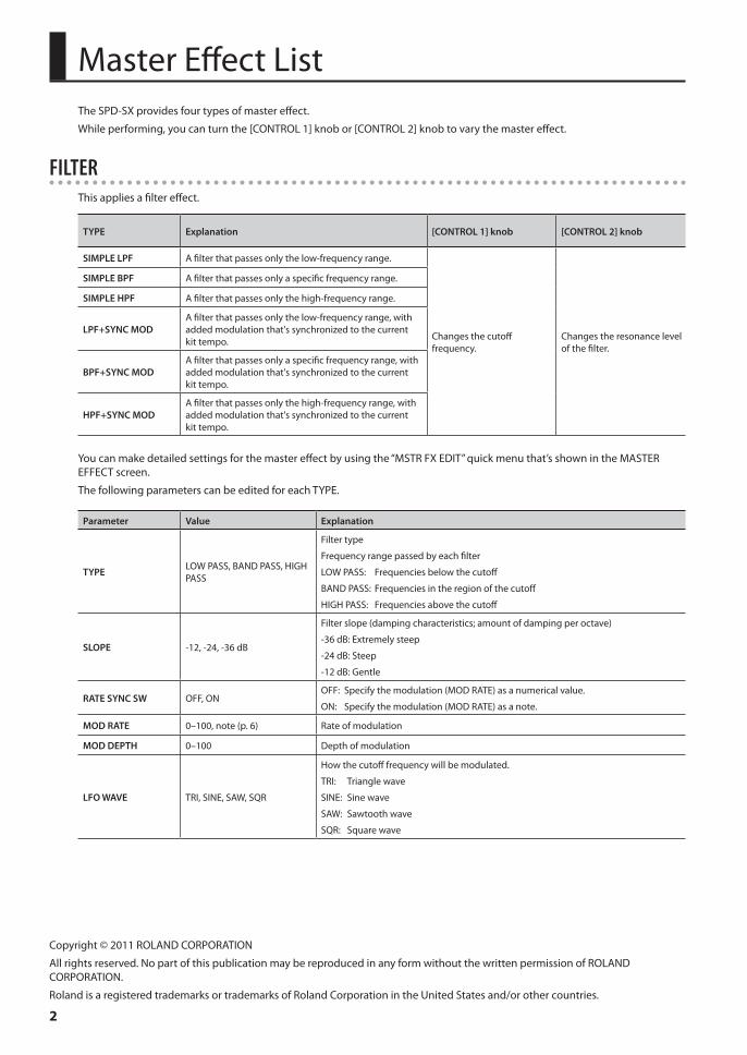
Master Effect ListThe SPD-SX provides four types of master effect.
While performing, you can turn the [CONTROL 1] knob or [CONTROL 2] knob to vary the master effect.
FILTERThis applies a filter effect.
TYPE Explanation [CONTROL 1] knob [CONTROL 2] knob
SIMPLE LPF A filter that passes only the low-frequency range.
Changes the cutoff frequency.
Changes the resonance level of the filter.
SIMPLE BPF A filter that passes only a specific frequency range.
SIMPLE HPF A filter that passes only the high-frequency range.
LPF+SYNC MODA filter that passes only the low-frequency range, with added modulation that's synchronized to the current kit tempo.
BPF+SYNC MODA filter that passes only a specific frequency range, with added modulation that's synchronized to the current kit tempo.
HPF+SYNC MODA filter that passes only the high-frequency range, with added modulation that's synchronized to the current kit tempo.
You can make detailed settings for the master effect by using the “MSTR FX EDIT” quick menu that’s shown in the MASTER EFFECT screen.
The following parameters can be edited for each TYPE.
Parameter Value Explanation
TYPE LOW PASS, BAND PASS, HIGH PASS
Filter type
Frequency range passed by each filter
LOW PASS: Frequencies below the cutoff
BAND PASS: Frequencies in the region of the cutoff
HIGH PASS: Frequencies above the cutoff
SLOPE -12, -24, -36 dB
Filter slope (damping characteristics; amount of damping per octave)
-36 dB: Extremely steep
-24 dB: Steep
-12 dB: Gentle
RATE SYNC SW OFF, ONOFF: Specify the modulation (MOD RATE) as a numerical value.
ON: Specify the modulation (MOD RATE) as a note.
MOD RATE 0–100, note (p. 6) Rate of modulation
MOD DEPTH 0–100 Depth of modulation
LFO WAVE TRI, SINE, SAW, SQR
How the cutoff frequency will be modulated.
TRI: Triangle wave
SINE: Sine wave
SAW: Sawtooth wave
SQR: Square wave
Copyright © 2011 ROLAND CORPORATION
All rights reserved. No part of this publication may be reproduced in any form without the written permission of ROLAND CORPORATION.
Roland is a registered trademarks or trademarks of Roland Corporation in the United States and/or other countries.
Master Effect List
3
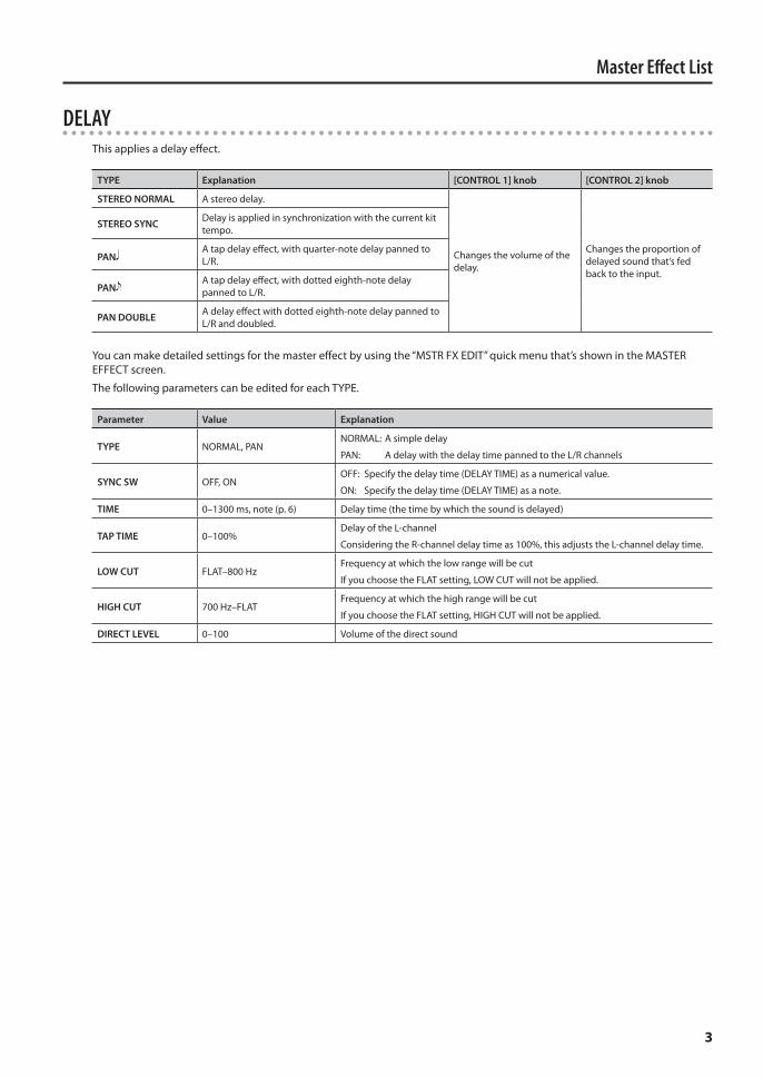
DELAYThis applies a delay effect.
TYPE Explanation [CONTROL 1] knob [CONTROL 2] knob
STEREO NORMAL A stereo delay.
Changes the volume of the delay.
Changes the proportion of delayed sound that’s fed back to the input.
STEREO SYNC Delay is applied in synchronization with the current kit tempo.
PANA tap delay effect, with quarter-note delay panned to L/R.
PANA tap delay effect, with dotted eighth-note delay panned to L/R.
PAN DOUBLE A delay effect with dotted eighth-note delay panned to L/R and doubled.
You can make detailed settings for the master effect by using the “MSTR FX EDIT” quick menu that’s shown in the MASTER EFFECT screen.
The following parameters can be edited for each TYPE.
Parameter Value Explanation
TYPE NORMAL, PANNORMAL: A simple delay
PAN: A delay with the delay time panned to the L/R channels
SYNC SW OFF, ONOFF: Specify the delay time (DELAY TIME) as a numerical value.
ON: Specify the delay time (DELAY TIME) as a note.
TIME 0–1300 ms, note (p. 6) Delay time (the time by which the sound is delayed)
TAP TIME 0–100%Delay of the L-channel
Considering the R-channel delay time as 100%, this adjusts the L-channel delay time.
LOW CUT FLAT–800 HzFrequency at which the low range will be cut
If you choose the FLAT setting, LOW CUT will not be applied.
HIGH CUT 700 Hz–FLATFrequency at which the high range will be cut
If you choose the FLAT setting, HIGH CUT will not be applied.
DIRECT LEVEL 0–100 Volume of the direct sound
Master Effect List
4
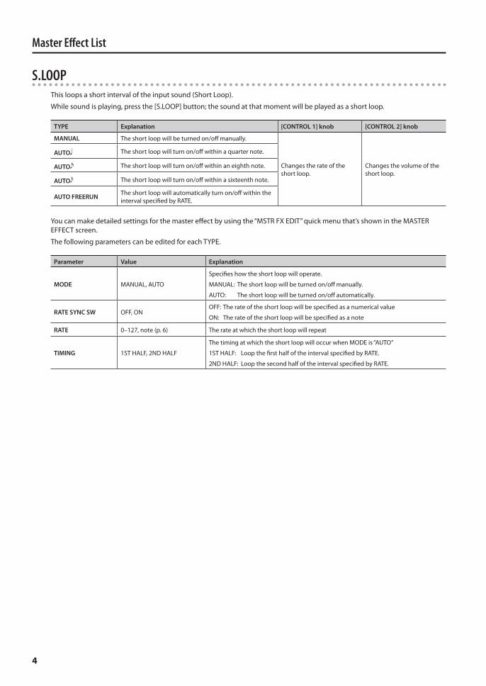
S.LOOPThis loops a short interval of the input sound (Short Loop).
While sound is playing, press the [S.LOOP] button; the sound at that moment will be played as a short loop.
TYPE Explanation [CONTROL 1] knob [CONTROL 2] knob
MANUAL The short loop will be turned on/off manually.
Changes the rate of the short loop.
Changes the volume of the short loop.
AUTO The short loop will turn on/off within a quarter note.
AUTO The short loop will turn on/off within an eighth note.
AUTO The short loop will turn on/off within a sixteenth note.
AUTO FREERUN The short loop will automatically turn on/off within the interval specified by RATE.
You can make detailed settings for the master effect by using the “MSTR FX EDIT” quick menu that’s shown in the MASTER EFFECT screen.
The following parameters can be edited for each TYPE.
Parameter Value Explanation
MODE MANUAL, AUTO
Specifies how the short loop will operate.
MANUAL: The short loop will be turned on/off manually.
AUTO: The short loop will be turned on/off automatically.
RATE SYNC SW OFF, ONOFF: The rate of the short loop will be specified as a numerical value
ON: The rate of the short loop will be specified as a note
RATE 0–127, note (p. 6) The rate at which the short loop will repeat
TIMING 1ST HALF, 2ND HALF
The timing at which the short loop will occur when MODE is “AUTO”
1ST HALF: Loop the first half of the interval specified by RATE.
2ND HALF: Loop the second half of the interval specified by RATE.

Master Effect List
5
FXThis applies the effect of the specified TYPE.
TYPE Explanation [CONTROL 1] knob [CONTROL 2] knob
THRU No effect will apply. - - - - - -
STEREO DELAY A stereo delay.Adjusts the volume of the delay.
Adjusts the amount of delayed sound that’s fed back to the input.SYNC DELAY Applies a delay that’s synchronized to the current kit
tempo.
TAPE ECHO A classic tape echo effect. Adjusts the tape speed.Adjusts the amount of repetition for the echo sound.
CHORUS Applies chorus. Adjusts the volume of the chorus.
Adjusts the depth of modulation.
FLANGERA stereo flanger.
This produces a metallic resonance reminiscent of a jet airplane taking off or landing.
Adjusts the rate of modulation.
Adjusts the depth of modulation.
STEP FLANGER The pitch of the flanger sound will change in steps. Adjusts the rate of modulation.
Adjusts the rate of pitch change.
PHASERA stereo phaser.
This creates modulation by adding a phase-shifted copy to the original sound.
Adjusts the rate of modulation.
Adjusts the depth of modulation.
STEP PHASER A phaser effect that changes in steps. Adjusts the rate of modulation.
Adjusts the rate of stepwise change.
EQUALIZER Modifies the tonal character. - - - - - -
COMPRESSOR Makes the overall volume more consistent by limiting loud sounds and boosting soft sounds. - - - - - -
FILTER Applies a filter effect. Adjusts the cutoff frequency. Adjusts the rate at which the cutoff frequency will change.
FILT+DRIVE A low-pass filter with overdrive; cuts the high-frequency range, and adds distortion. Adjusts the cutoff frequency. Adjusts the amount of
overdrive distortion.
ISOLATORAn equalizer that drastically reduces the volume, creating unique effects by cutting the volume of specific frequency regions.
Adjusts the amount of boost/cut in the low-frequency range.
Adjusts the amount of boost/cut in the high-frequency range.
TOUCH WAH Applies a wah effect by varying a filter according to the volume of the performance.
Adjusts the sensitivity at which the filter will change.
Adjusts the center frequency at which the wah effect is applied.
DISTORTION An effect that produces long sustain by distorting the sound.
Adjusts the volume balance between the direct sound and the effect sound.
- - -
RING MOD Generates bell-like sounds by applying amplitude modulation (AM) to the input signal.
Adjusts the depth of amplitude modulation.
Adjusts the frequency at which modulation is applied.
PITCH SHIFT Shifts the pitch of the original sound. Adjusts the amount of pitch shift.
Adjusts the proportion of pitch-shifted sound that is fed back to the input.
VIBRATO Applies vibrato. Adjusts the vibrato rate. Adjusts the vibrato depth.
REVERB Applies reverberation. Adjusts the volume of reverb. - - -
SLICERBy repeatedly cutting the sound, this creates the sensation that a rhythmic backing phrase is impressed on the sound.
Adjusts the rate at which the sound is cut. - - -
You can make detailed settings for the master effect by using the “MSTR FX EDIT” quick menu that’s shown in the MASTER EFFECT screen.
For each TYPE of the FX group you can make settings for the same parameters as the Kit effects.
For details on the parameters for which settings can be made, refer to the “Kit Effect List” (p. 6).
* Parameters that are assigned to the [CONTROL 1] knob or [CONTROL 2] knob are not shown in the screen for detailed settings.
6
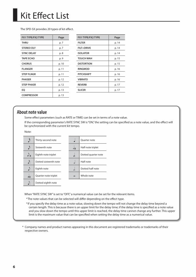
Kit Effect ListThe SPD-SX provides 20 types of kit effect.
FX1 TYPE/FX2 TYPE Page FX1 TYPE/FX2 TYPE Page
THRU p. 7 FILTER p. 14
STEREO DLY p. 7 FILT+DRIVE p. 14
SYNC DELAY p. 8 ISOLATOR p. 14
TAPE ECHO p. 9 TOUCH WAH p. 15
CHORUS p. 10 DISTORTION p. 15
FLANGER p. 11 RINGMOD p. 16
STEP FLNGR p. 11 PITCHSHIFT p. 16
PHASER p. 12 VIBRATO p. 16
STEP PHASR p. 12 REVERB p. 17
EQ p. 13 SLICER p. 17
COMPRESSOR p. 13
About note valueSome effect parameters (such as RATE or TIME) can be set in terms of a note value.
If the corresponding parameter’s RATE SYNC SW is “ON,” the setting can be specified as a note value, and the effect will be synchronized with the current kit tempo.
Note:
Thirty-second note Quarter note
Sixteenth note Half-note triplet
Eighth-note triplet Dotted quarter note
Dotted sixteenth note Half note
Eighth note Dotted half note
Quarter-note triplet Whole note
Dotted eighth note
When “RATE SYNC SW” is set to “OFF,” a numerical value can be set for the relevant items.
* The note values that can be selected will differ depending on the effect type.
* If you specify the delay time as a note value, slowing down the tempo will not change the delay time beyond a certain length. This is because there is an upper limit for the delay time; if the delay time is specified as a note value and you slow down the tempo until this upper limit is reached, the delay time cannot change any further. This upper limit is the maximum value that can be specified when setting the delay time as a numerical value.
* Company names and product names appearing in this document are registered trademarks or trademarks of their respective owners.
Kit Effect List
7
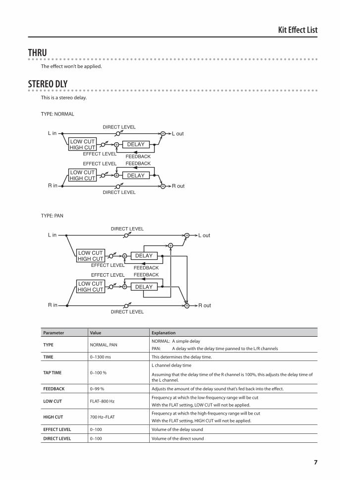
THRUThe effect won’t be applied.
STEREO DLYThis is a stereo delay.
TYPE: NORMAL
R in R out
L in L out
FEEDBACK
DIRECT LEVEL
LOW CUTHIGH CUT DELAY
EFFECT LEVEL
FEEDBACK
DIRECT LEVEL
LOW CUTHIGH CUT DELAY
EFFECT LEVEL
TYPE: PAN
R in R out
L in L out
FEEDBACK
DIRECT LEVEL
LOW CUTHIGH CUT DELAY
EFFECT LEVEL
FEEDBACK
DIRECT LEVEL
LOW CUTHIGH CUT DELAY
EFFECT LEVEL
Parameter Value Explanation
TYPE NORMAL, PANNORMAL: A simple delay
PAN: A delay with the delay time panned to the L/R channels
TIME 0–1300 ms This determines the delay time.
TAP TIME 0–100 %
L channel delay time
Assuming that the delay time of the R channel is 100%, this adjusts the delay time of the L channel.
FEEDBACK 0–99 % Adjusts the amount of the delay sound that’s fed back into the effect.
LOW CUT FLAT–800 HzFrequency at which the low-frequency range will be cut
With the FLAT setting, LOW CUT will not be applied.
HIGH CUT 700 Hz–FLATFrequency at which the high-frequency range will be cut
With the FLAT setting, HIGH CUT will not be applied.
EFFECT LEVEL 0–100 Volume of the delay sound
DIRECT LEVEL 0–100 Volume of the direct sound
Kit Effect List
8
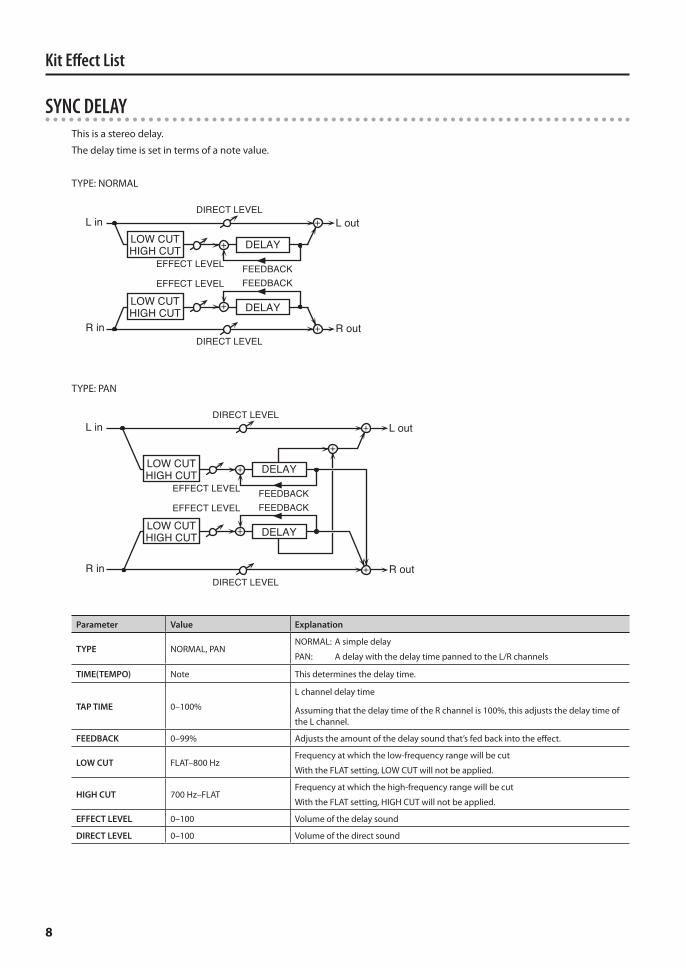
SYNC DELAYThis is a stereo delay.
The delay time is set in terms of a note value.
TYPE: NORMAL
R in R out
L in L out
FEEDBACK
DIRECT LEVEL
LOW CUTHIGH CUT DELAY
EFFECT LEVEL
FEEDBACK
DIRECT LEVEL
LOW CUTHIGH CUT DELAY
EFFECT LEVEL
TYPE: PAN
R in R out
L in L out
FEEDBACK
DIRECT LEVEL
LOW CUTHIGH CUT DELAY
EFFECT LEVEL
FEEDBACK
DIRECT LEVEL
LOW CUTHIGH CUT DELAY
EFFECT LEVEL
Parameter Value Explanation
TYPE NORMAL, PANNORMAL: A simple delay
PAN: A delay with the delay time panned to the L/R channels
TIME(TEMPO) Note This determines the delay time.
TAP TIME 0–100%
L channel delay time
Assuming that the delay time of the R channel is 100%, this adjusts the delay time of the L channel.
FEEDBACK 0–99% Adjusts the amount of the delay sound that’s fed back into the effect.
LOW CUT FLAT–800 HzFrequency at which the low-frequency range will be cut
With the FLAT setting, LOW CUT will not be applied.
HIGH CUT 700 Hz–FLATFrequency at which the high-frequency range will be cut
With the FLAT setting, HIGH CUT will not be applied.
EFFECT LEVEL 0–100 Volume of the delay sound
DIRECT LEVEL 0–100 Volume of the direct sound
Kit Effect List
9
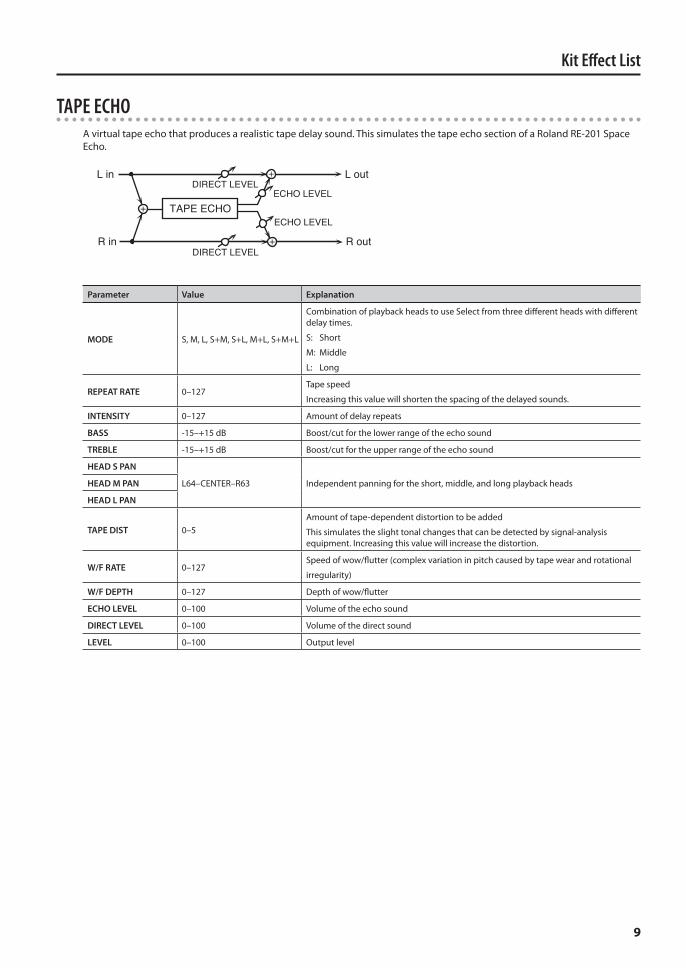
TAPE ECHOA virtual tape echo that produces a realistic tape delay sound. This simulates the tape echo section of a Roland RE-201 Space Echo.
ECHO LEVEL
ECHO LEVEL
L in
R in
L out
R out
TAPE ECHO
DIRECT LEVEL
DIRECT LEVEL
Parameter Value Explanation
MODE S, M, L, S+M, S+L, M+L, S+M+L
Combination of playback heads to use Select from three different heads with different delay times.
S: Short
M: Middle
L: Long
REPEAT RATE 0–127Tape speed
Increasing this value will shorten the spacing of the delayed sounds.
INTENSITY 0–127 Amount of delay repeats
BASS -15–+15 dB Boost/cut for the lower range of the echo sound
TREBLE -15–+15 dB Boost/cut for the upper range of the echo sound
HEAD S PAN
L64–CENTER–R63 Independent panning for the short, middle, and long playback headsHEAD M PAN
HEAD L PAN
TAPE DIST 0–5Amount of tape-dependent distortion to be added
This simulates the slight tonal changes that can be detected by signal-analysis equipment. Increasing this value will increase the distortion.
W/F RATE 0–127Speed of wow/flutter (complex variation in pitch caused by tape wear and rotational
irregularity)
W/F DEPTH 0–127 Depth of wow/flutter
ECHO LEVEL 0–100 Volume of the echo sound
DIRECT LEVEL 0–100 Volume of the direct sound
LEVEL 0–100 Output level

Kit Effect List
10
CHORUSThis applies a chorus effect.
MODE: MONO
L in
R in
L out
R outDIRECT LEVEL
DIRECT LEVEL
CHORUS
EFFECT LEVEL
MODE: STEREO 1
L in
R in
L out
R outDIRECT LEVEL
DIRECT LEVEL
EFFECT LEVEL
CHORUS
MODE: STEREO 2
L in
R in
L out
R outDIRECT LEVEL
DIRECT LEVEL
EFFECT LEVEL
CHORUS
Parameter Value Explanation
MODE MONO, STEREO 1, STEREO 2
MONO: A chorus that outputs the same sound to the L/R channels
STEREO 1: A stereo two-stage chorus that adds a separate chorus sound to the L/R channels
STEREO 2: The original sound is output to the L-channel, and the effect sound to the R-channel.
RATE 0–100 Frequency of modulation
DEPTH 0–100 Depth of modulation
PRE DELAY 0.0–40.0 ms Time from when the original sound is output until the effect sound is output
LOW CUT FLAT–800 HzFrequency at which the low-frequency range will be cut
With the FLAT setting, LOW CUT will not be applied.
HIGH CUT 700 Hz–FLATFrequency at which the high-frequency range will be cut
With the FLAT setting, HIGH CUT will not be applied.
EFFECT LEVEL 0–100 Volume of the effect sound
DIRECT LEVEL 0–100 Volume of the direct sound
Kit Effect List
11
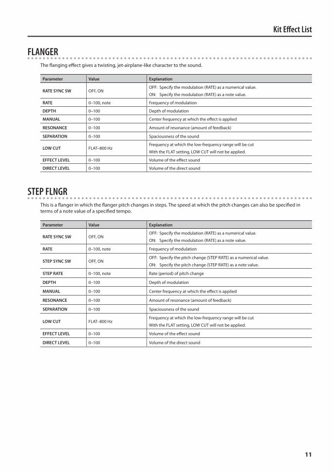
FLANGERThe flanging effect gives a twisting, jet-airplane-like character to the sound.
Parameter Value Explanation
RATE SYNC SW OFF, ONOFF: Specify the modulation (RATE) as a numerical value.
ON: Specify the modulation (RATE) as a note value.
RATE 0–100, note Frequency of modulation
DEPTH 0–100 Depth of modulation
MANUAL 0–100 Center frequency at which the effect is applied
RESONANCE 0–100 Amount of resonance (amount of feedback)
SEPARATION 0–100 Spaciousness of the sound
LOW CUT FLAT–800 HzFrequency at which the low-frequency range will be cut
With the FLAT setting, LOW CUT will not be applied.
EFFECT LEVEL 0–100 Volume of the effect sound
DIRECT LEVEL 0–100 Volume of the direct sound
STEP FLNGRThis is a flanger in which the flanger pitch changes in steps. The speed at which the pitch changes can also be specified in terms of a note value of a specified tempo.
Parameter Value Explanation
RATE SYNC SW OFF, ONOFF: Specify the modulation (RATE) as a numerical value.
ON: Specify the modulation (RATE) as a note value.
RATE 0–100, note Frequency of modulation
STEP SYNC SW OFF, ONOFF: Specify the pitch change (STEP RATE) as a numerical value.
ON: Specify the pitch change (STEP RATE) as a note value.
STEP RATE 0–100, note Rate (period) of pitch change
DEPTH 0–100 Depth of modulation
MANUAL 0–100 Center frequency at which the effect is applied
RESONANCE 0–100 Amount of resonance (amount of feedback)
SEPARATION 0–100 Spaciousness of the sound
LOW CUT FLAT–800 HzFrequency at which the low-frequency range will be cut
With the FLAT setting, LOW CUT will not be applied.
EFFECT LEVEL 0–100 Volume of the effect sound
DIRECT LEVEL 0–100 Volume of the direct sound
Kit Effect List
12
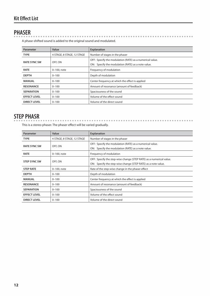
PHASERA phase-shifted sound is added to the original sound and modulated.
Parameter Value Explanation
TYPE 4 STAGE, 8 STAGE, 12 STAGE Number of stages in the phaser
RATE SYNC SW OFF, ONOFF: Specify the modulation (RATE) as a numerical value.
ON: Specify the modulation (RATE) as a note value.
RATE 0–100, note Frequency of modulation
DEPTH 0–100 Depth of modulation
MANUAL 0–100 Center frequency at which the effect is applied
RESONANCE 0–100 Amount of resonance (amount of feedback)
SEPARATION 0–100 Spaciousness of the sound
EFFECT LEVEL 0–100 Volume of the effect sound
DIRECT LEVEL 0–100 Volume of the direct sound
STEP PHASRThis is a stereo phaser. The phaser effect will be varied gradually.
Parameter Value Explanation
TYPE 4 STAGE, 8 STAGE, 12 STAGE Number of stages in the phaser
RATE SYNC SW OFF, ONOFF: Specify the modulation (RATE) as a numerical value.
ON: Specify the modulation (RATE) as a note value.
RATE 0–100, note Frequency of modulation
STEP SYNC SW OFF, ONOFF: Specify the step-wise change (STEP RATE) as a numerical value.
ON: Specify the step-wise change (STEP RATE) as a note value.
STEP RATE 0–100, note Rate of the step-wise change in the phaser effect
DEPTH 0–100 Depth of modulation
MANUAL 0–100 Center frequency at which the effect is applied
RESONANCE 0–100 Amount of resonance (amount of feedback)
SEPARATION 0–100 Spaciousness of the sound
EFFECT LEVEL 0–100 Volume of the effect sound
DIRECT LEVEL 0–100 Volume of the direct sound
Kit Effect List
13
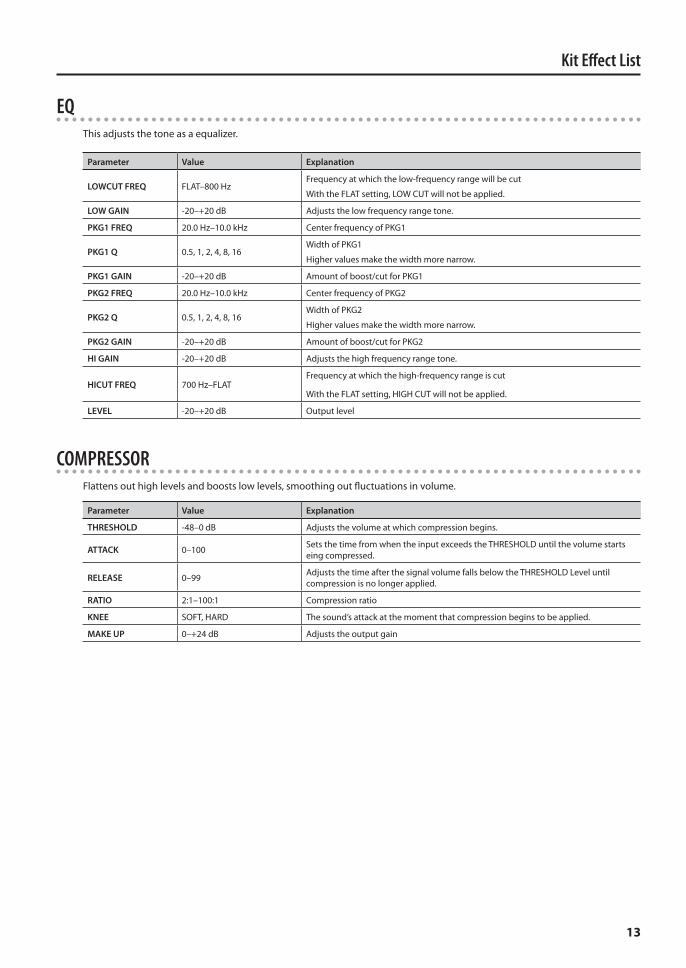
EQThis adjusts the tone as a equalizer.
Parameter Value Explanation
LOWCUT FREQ FLAT–800 HzFrequency at which the low-frequency range will be cut
With the FLAT setting, LOW CUT will not be applied.
LOW GAIN -20–+20 dB Adjusts the low frequency range tone.
PKG1 FREQ 20.0 Hz–10.0 kHz Center frequency of PKG1
PKG1 Q 0.5, 1, 2, 4, 8, 16Width of PKG1
Higher values make the width more narrow.
PKG1 GAIN -20–+20 dB Amount of boost/cut for PKG1
PKG2 FREQ 20.0 Hz–10.0 kHz Center frequency of PKG2
PKG2 Q 0.5, 1, 2, 4, 8, 16Width of PKG2
Higher values make the width more narrow.
PKG2 GAIN -20–+20 dB Amount of boost/cut for PKG2
HI GAIN -20–+20 dB Adjusts the high frequency range tone.
HICUT FREQ 700 Hz–FLATFrequency at which the high-frequency range is cut
With the FLAT setting, HIGH CUT will not be applied.
LEVEL -20–+20 dB Output level
COMPRESSORFlattens out high levels and boosts low levels, smoothing out fluctuations in volume.
Parameter Value Explanation
THRESHOLD -48–0 dB Adjusts the volume at which compression begins.
ATTACK 0–100 Sets the time from when the input exceeds the THRESHOLD until the volume starts eing compressed.
RELEASE 0–99 Adjusts the time after the signal volume falls below the THRESHOLD Level until compression is no longer applied.
RATIO 2:1–100:1 Compression ratio
KNEE SOFT, HARD The sound’s attack at the moment that compression begins to be applied.
MAKE UP 0–+24 dB Adjusts the output gain
Kit Effect List
14
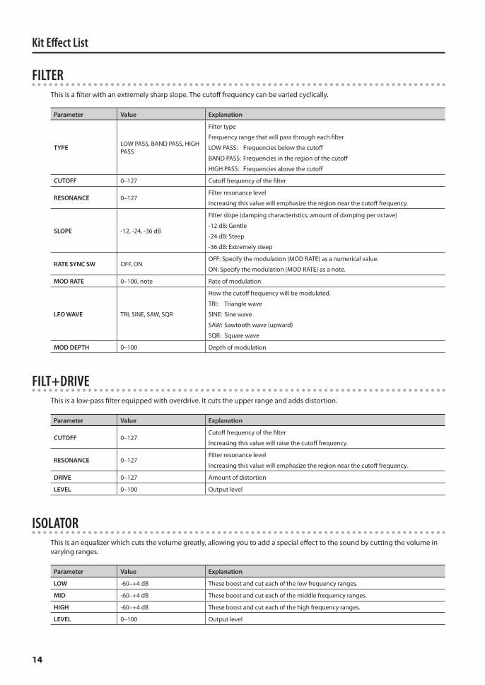
FILTERThis is a filter with an extremely sharp slope. The cutoff frequency can be varied cyclically.
Parameter Value Explanation
TYPE LOW PASS, BAND PASS, HIGH PASS
Filter type
Frequency range that will pass through each filter
LOW PASS: Frequencies below the cutoff
BAND PASS: Frequencies in the region of the cutoff
HIGH PASS: Frequencies above the cutoff
CUTOFF 0–127 Cutoff frequency of the filter
RESONANCE 0–127Filter resonance level
Increasing this value will emphasize the region near the cutoff frequency.
SLOPE -12, -24, -36 dB
Filter slope (damping characteristics; amount of damping per octave)
-12 dB: Gentle
-24 dB: Steep
-36 dB: Extremely steep
RATE SYNC SW OFF, ONOFF: Specify the modulation (MOD RATE) as a numerical value.
ON: Specify the modulation (MOD RATE) as a note.
MOD RATE 0–100, note Rate of modulation
LFO WAVE TRI, SINE, SAW, SQR
How the cutoff frequency will be modulated.
TRI: Triangle wave
SINE: Sine wave
SAW: Sawtooth wave (upward)
SQR: Square wave
MOD DEPTH 0–100 Depth of modulation
FILT+DRIVEThis is a low-pass filter equipped with overdrive. It cuts the upper range and adds distortion.
Parameter Value Explanation
CUTOFF 0–127Cutoff frequency of the filter
Increasing this value will raise the cutoff frequency.
RESONANCE 0–127Filter resonance level
Increasing this value will emphasize the region near the cutoff frequency.
DRIVE 0–127 Amount of distortion
LEVEL 0–100 Output level
ISOLATORThis is an equalizer which cuts the volume greatly, allowing you to add a special effect to the sound by cutting the volume in varying ranges.
Parameter Value Explanation
LOW -60–+4 dB These boost and cut each of the low frequency ranges.
MID -60–+4 dB These boost and cut each of the middle frequency ranges.
HIGH -60–+4 dB These boost and cut each of the high frequency ranges.
LEVEL 0–100 Output level
Kit Effect List
15
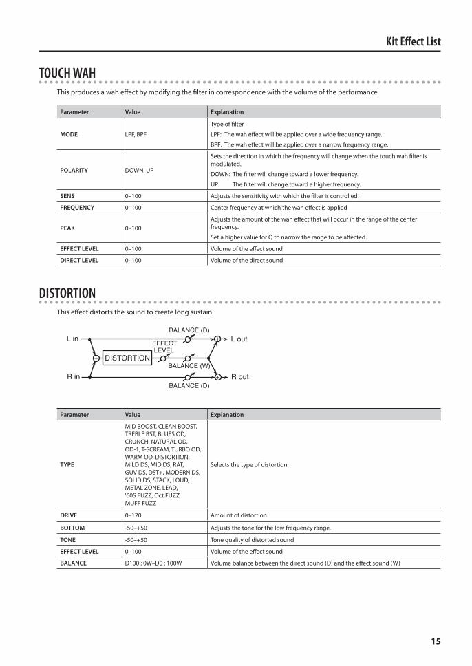
TOUCH WAHThis produces a wah effect by modifying the filter in correspondence with the volume of the performance.
Parameter Value Explanation
MODE LPF, BPF
Type of filter
LPF: The wah effect will be applied over a wide frequency range.
BPF: The wah effect will be applied over a narrow frequency range.
POLARITY DOWN, UP
Sets the direction in which the frequency will change when the touch wah filter is modulated.
DOWN: The filter will change toward a lower frequency.
UP: The filter will change toward a higher frequency.
SENS 0–100 Adjusts the sensitivity with which the filter is controlled.
FREQUENCY 0–100 Center frequency at which the wah effect is applied
PEAK 0–100Adjusts the amount of the wah effect that will occur in the range of the center frequency.
Set a higher value for Q to narrow the range to be affected.
EFFECT LEVEL 0–100 Volume of the effect sound
DIRECT LEVEL 0–100 Volume of the direct sound
DISTORTIONThis effect distorts the sound to create long sustain.
L in
R in
L out
R outBALANCE (W)
BALANCE (D)
BALANCE (D)
DISTORTION
EFFECT LEVEL
Parameter Value Explanation
TYPE
MID BOOST, CLEAN BOOST, TREBLE BST, BLUES OD, CRUNCH, NATURAL OD, OD-1, T-SCREAM, TURBO OD, WARM OD, DISTORTION, MILD DS, MID DS, RAT, GUV DS, DST+, MODERN DS, SOLID DS, STACK, LOUD, METAL ZONE, LEAD, '60S FUZZ, Oct FUZZ, MUFF FUZZ
Selects the type of distortion.
DRIVE 0–120 Amount of distortion
BOTTOM -50–+50 Adjusts the tone for the low frequency range.
TONE -50–+50 Tone quality of distorted sound
EFFECT LEVEL 0–100 Volume of the effect sound
BALANCE D100 : 0W–D0 : 100W Volume balance between the direct sound (D) and the effect sound (W)
Kit Effect List
16
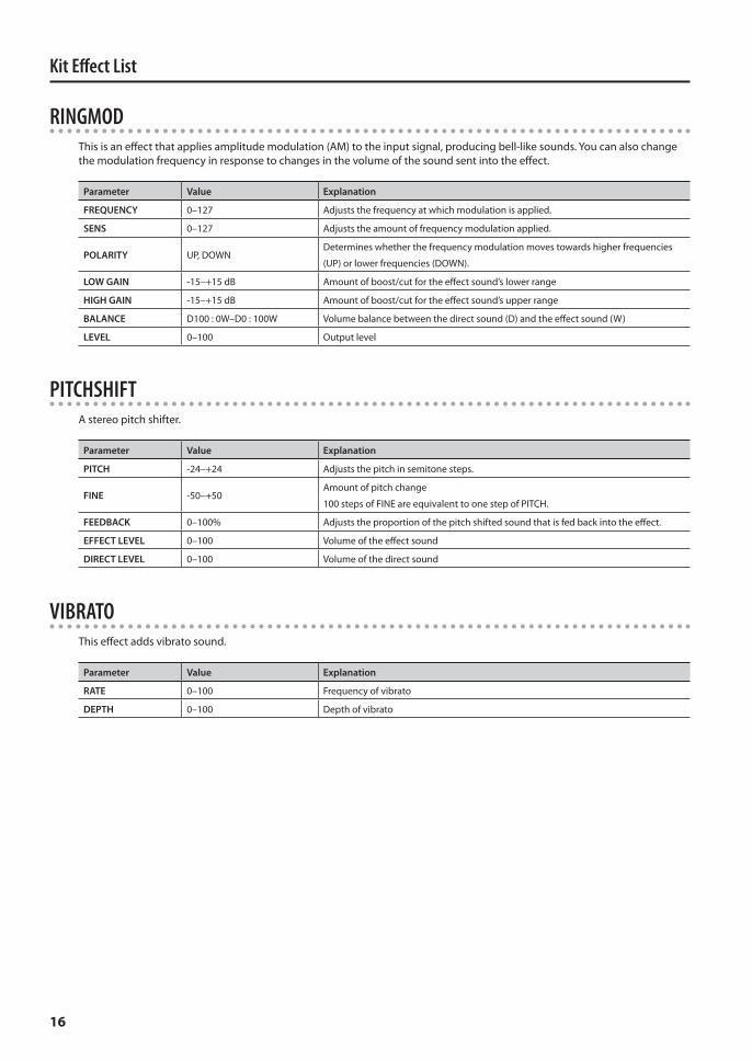
RINGMODThis is an effect that applies amplitude modulation (AM) to the input signal, producing bell-like sounds. You can also change the modulation frequency in response to changes in the volume of the sound sent into the effect.
Parameter Value Explanation
FREQUENCY 0–127 Adjusts the frequency at which modulation is applied.
SENS 0–127 Adjusts the amount of frequency modulation applied.
POLARITY UP, DOWNDetermines whether the frequency modulation moves towards higher frequencies
(UP) or lower frequencies (DOWN).
LOW GAIN -15–+15 dB Amount of boost/cut for the effect sound’s lower range
HIGH GAIN -15–+15 dB Amount of boost/cut for the effect sound’s upper range
BALANCE D100 : 0W–D0 : 100W Volume balance between the direct sound (D) and the effect sound (W)
LEVEL 0–100 Output level
PITCHSHIFTA stereo pitch shifter.
Parameter Value Explanation
PITCH -24–+24 Adjusts the pitch in semitone steps.
FINE -50–+50Amount of pitch change
100 steps of FINE are equivalent to one step of PITCH.
FEEDBACK 0–100% Adjusts the proportion of the pitch shifted sound that is fed back into the effect.
EFFECT LEVEL 0–100 Volume of the effect sound
DIRECT LEVEL 0–100 Volume of the direct sound
VIBRATOThis effect adds vibrato sound.
Parameter Value Explanation
RATE 0–100 Frequency of vibrato
DEPTH 0–100 Depth of vibrato
Kit Effect List
17
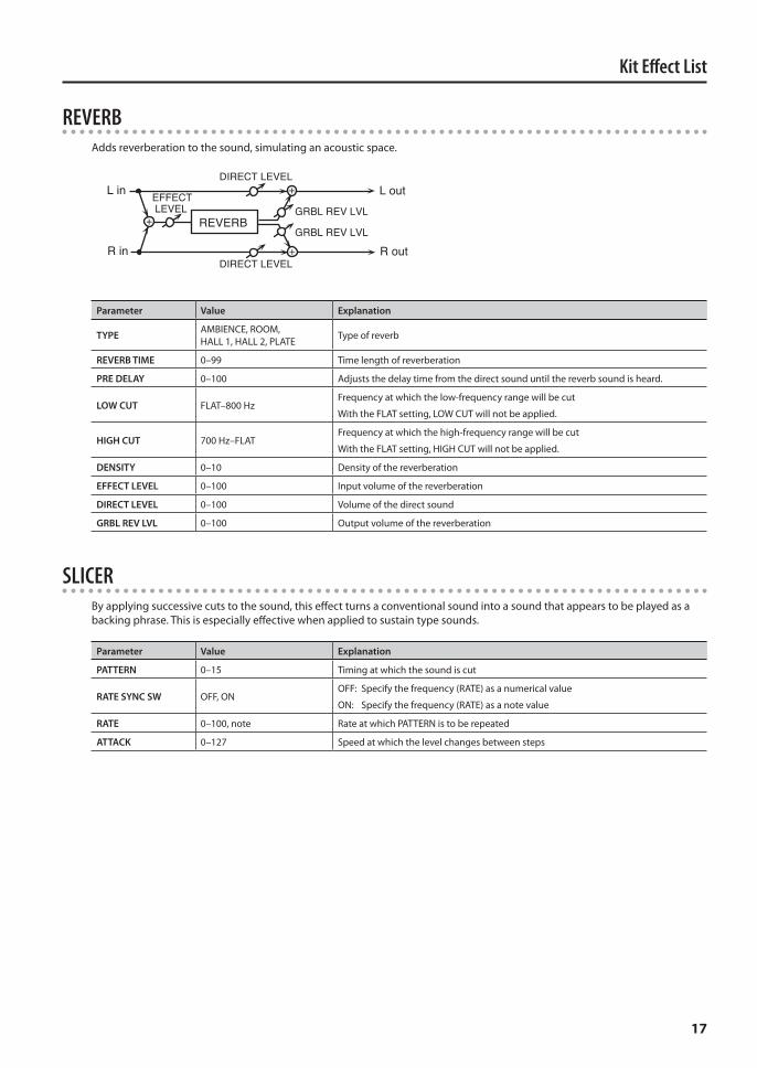
REVERBAdds reverberation to the sound, simulating an acoustic space.
L in
R in
L out
R outDIRECT LEVEL
DIRECT LEVEL
EFFECT LEVEL
REVERBGRBL REV LVL
GRBL REV LVL
Parameter Value Explanation
TYPE AMBIENCE, ROOM, HALL 1, HALL 2, PLATE Type of reverb
REVERB TIME 0–99 Time length of reverberation
PRE DELAY 0–100 Adjusts the delay time from the direct sound until the reverb sound is heard.
LOW CUT FLAT–800 HzFrequency at which the low-frequency range will be cut
With the FLAT setting, LOW CUT will not be applied.
HIGH CUT 700 Hz–FLATFrequency at which the high-frequency range will be cut
With the FLAT setting, HIGH CUT will not be applied.
DENSITY 0–10 Density of the reverberation
EFFECT LEVEL 0–100 Input volume of the reverberation
DIRECT LEVEL 0–100 Volume of the direct sound
GRBL REV LVL 0–100 Output volume of the reverberation
SLICERBy applying successive cuts to the sound, this effect turns a conventional sound into a sound that appears to be played as a backing phrase. This is especially effective when applied to sustain type sounds.
Parameter Value Explanation
PATTERN 0–15 Timing at which the sound is cut
RATE SYNC SW OFF, ONOFF: Specify the frequency (RATE) as a numerical value
ON: Specify the frequency (RATE) as a note value
RATE 0–100, note Rate at which PATTERN is to be repeated
ATTACK 0–127 Speed at which the level changes between steps

1PS