Embed Size (px)
Citation preview

Sketchify Overview Z. OBRENOVIC Eindhoven University of Technology, Eindhoven, The Netherlands.
1 INTRODUCTION In the following sections, we several basic elements of Sketchify, including:
• Sketchify’s freehand drawing mode, used to create bitmap images, • Active regions, used to create a range of interactive effects, • Events and actions in Sketchify, used to support event-driven definition of
interaction, • Timers, used to produce advanced dynamic effects, • Macros, used to group actions, • Sketchify’s animation support, • Formulas and templates in Sketchify, and • Advanced options
2 FREEHAND DRAWING In Sketchify, designers can create pages that consist of two types of elements: background images (Figure A.1), and active regions.
Fig. A.1. The Sketchify image editor supports well-known bitmap image operations and tools, such as a brush and eraser to create drawings, importing an image from file, or opening the drawn image in an external editor for more complex image composition.

Background images are created in the Sketchify drawing mode. From the designers’ point of view, the Sketchify drawing mode does not look much different from what they might expect from other simple image editors, as our environment supports most standard options for free-hand drawing. A designer, for example, can use drawing tools, such as a brush or eraser, to create drawings. Working with multiple image layers is supported as well.
3 ACTIVE REGIONS Most interactive effects in Sketchify are defined by means of active regions. An active region is a rectangular part in a page that can display drawings and text, but that can additionally capture user events and be graphically transformed (with transformations such as rotation, translation, or perspective mapping).
3.1 Creating Images in Active Regions The images (or drawings) that are associated with active regions can be created in several ways (Figure A.2 and A.3): • By drawing them in the active regions image editor or in an external image editor, • By importing them from a file or pasting them from the clipboard, • By extracting a region from a background image created in drawing mode, • By specifying a path or URL to an image file, • By dynamically capturing them from screen, • By defining a text to be rendered, or a more complex object including both graphics
and text in a standardized format such as HyperText Markup Language (HTML) code, or Scalable Markup Language (SVG) code.
(a) (b)
(c)
Fig. A.2. Some of the ways to create an image in an active region: (a) extracting it from a background image, (b) as text or text file, (c) by capturing it from a part of the screen.

(a)
(b)
Fig. A.3. Creating an image in an active region using markup languages: (a) from HyperText Markup Language (HTML) code, and (b) from Scalable Vector Graphics (SVG) code.
3.2 Graphical Transformations of Active Regions Regardless of how an image is created, a designer can manipulate and transform such image using a range of transformations (Table A.I). Using mouse or pen, a designer can change the position, size, orientation, and perspective points of active regions. Additionally, through a more advanced interface, a range of other transformation is also possible, such as changing transparency, or 3D rotation (Figure A.4).
(a)
(c) (b)
Fig. A.4. Various forms of perspective graphical transformations of active regions: (a) manually specifying perspective points, (b) horizontal or vertical 3D rotation derives the perspective points from the specified angle, and (c) a user interface for setting the perceptual depth of regions.

Table A.I Some of the possible graphical transformations of active regions.
Transformation Description Position Position x Horizontal position (in pixels) Position y Vertical position (in pixels) Relative x Relative horizontal position (between 0 and 1) Relative y Relative vertical position (between 0 and 1) Trajectory position Relative trajectory position (between 0 and 1) Size Width Width (in pixels) Height Height (in pixels) Orientation Rotation Rotation in the image plane (in degrees) Image Transparency Image transparency (between 0 and 1) Visible Area Visible area x X position of top, left corner of the visible area Visible area y Y position of top, left corner of the visible area Visible area width Width of the visible area Visible are height Height of the visible area Motion Speed Speed of the region (pixels per second) Direction Direction of motion if speed is defined (in degrees) Pen Pen thickness The thickness of the trace left when the region is moving Shear Shear x Horizontal shear transformation Shear y Vertical shear transformation 3D rotation Horizontal 3d rotation Horizontal 3D rotation angle (in degrees) Vertical 3d rotation Vertical 3D rotation angle (in degrees) Perspective Perspective depth Perspective depth (between 0 and 1)

4 VARIABLES, FORMULAS AND TEMPLATES Properties of active regions and pages can also be specified indirectly through variables, formulas, and templates. Any property or expression that uses formulas and templates will be automatically evaluated when any of the variables in the formula/template is updated.
4.1 Formulas A designer can use formulas to derive values using diverse operators and functions, for example:
• =rot * 3, where the output value is calculated by multiplying the value of the variable ‘rot’ by a factor of 3,
• =sqrt(a^2 + b^2), where the value calculated is the square root of a sum of squares of values from variables ‘a’ and ‘b’.
All common arithmetic operators are supported, as well as the conditional if operation.
4.2 Templates Templates are a simple way to compose larger pieces of text by allowing variable names to be replaced by variable values, which are converted to text strings (Figure A.6).
Fig. A.6. Using string templates to set region properties. In this example, the template “Rotation is <%=rot%> degrees” is used to define the region text. The text will be refreshed and evaluated each time when the variable “rot” is updated.

5 EVENTS AND ACTIONS Sketchify enables an event-based description of interaction, where a designer can define the response to a range of interaction events (Table A.II). For each of these events one or more actions can be triggered (Table A.III).
Table A.II. Sketchify events. Mouse Events Continuous motion events (when user drags the region)
Discrete mouse events
Basic: – position x, position y – rotation Derived: – speed of dragging – trajectory position (if defined)
• Left Button Click/Press/Release • Middle Button Click/Press/Release • Right Button Click/Press/Release • Double Click • Mouse Entry/Exit • Wheel Up/Down
Keyboard Events • Key pressed/released Region Overlap Events (when two regions overlap)
Variable Events (when variable is updated and has particular value)
• Variable Updated • Variable Updated <condition>
Sketch Events • On sketch entry (when you open the sketch) • On sketch exit (when you close the sketch or move to another sketch)
Table A.III, Sketchify actions.
Sketch Actions Go to sketch Transition to another sketch Variable Actions Update variable sets the variable to given value Increment variable increments current value of the variable by a given number Append variable appends string to the existing content of the variable Timer actions Start timer Starts a timer Stop timer Stops a timer Macro Actions Start macro Starts a macro (a list of actions) Stop macro Stops a macro

6 ANIMATION Sketchify supports several ways to define animated effects, including: • Flip-book like animation, • Properties animation, and • Animation using timers (described in Section 7).
6.1 Flip Book Animation Sketchify flip book animation is analogous to traditional flipbook animation. A designer can create several image frames in an active region, and then animate them by defining the exposure time for each of the frames. A flip-book-like animation effect is created by looping through the images adopting the specified timing (Figure A.7).
Fig. A.7. Flip-book animation in Sketchify. An active region can contain more than one image (drawn or imported). The (relative) exposure time for each of these images can be specified. , A flip-book-like animation effect is created by looping through the image using the specified timing.
6.2 Properties Animation Sketchify supports simple animations for any of the numeric properties of pages and active regions (see Table A.I for some of them). To define such animations, only few parameters need to be specified: • Type of animation, which can be loop or pulse (once or forever), • Start and end values of the property, • Cycle duration, and • Optional time curve.
For example, Table A.IV illustrates simultaneous animation of the rotation and transparency of an active region. Table A.IV. Defining properties for the animation of an active region. In this example, two properties, rotation and transparency, are animated in a loop between their minimum and maximum values, with a cycle duration of 1 second.
Property Animation Type
Start Value
End Value Duration (sec)
Curve
Rotation Loop Forever 0 360 1.0 linear Transparency Loop Forever 0.0 1.0 1.0 linear

To simplify definition of this type of animations, we also provide an interface for interactively exploring various animation effects (Figure A.8).
Fig. A.8. A user interface for defining animation properties. In this example, each of the active region’s transformation properties (such as, position, rotation, transparency, perspective), can be animated by defining animation type, duration of the animation cycle, start and end values, as well as an optional time curve.
7 TIMERS Timers facilitate the definition of more complex animation and interaction effects. A timer can cycle more than once, or work as a “pulsar” (a value increases from its minimum value to its maximum value in the forward cycle, while it decreases in the backward cycle). Timers introduce two elements:
• A timer variable interpolator, and • A timeline with events.
7.1 Timer Variable Interpolator Timer interpolators enable continuous updating of numeric variables (Figure A.9). Timer interpolators are essential for animation effects. For example, we can define a timer with a cycle duration of 60 seconds and a resolution of one update per second to update the variable “orientation” from 0 to 360 degrees. This variable can for instance be used to control the orientation of an active region that simulates the handle of a clock.
Fig. A.9. A timer interpolator. During the timer cycle, the interpolator continuously changes one or more variables from their start to end values, and for each variable a different timer curve can be used. Mapping between time and variable values can also be nonlinear, using timer curves (Figure A.10). Timer curves enable non-linear mappings between actual time and variable values in timers. When no timer curve is specified, the timer changes variable
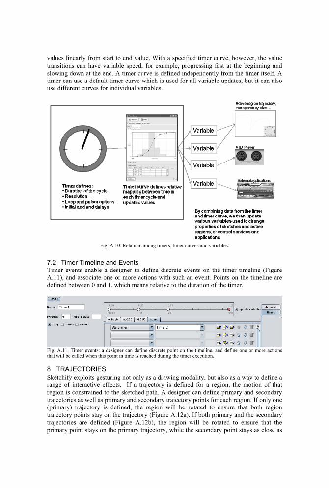
values linearly from start to end value. With a specified timer curve, however, the value transitions can have variable speed, for example, progressing fast at the beginning and slowing down at the end. A timer curve is defined independently from the timer itself. A timer can use a default timer curve which is used for all variable updates, but it can also use different curves for individual variables.
Fig. A.10. Relation among timers, timer curves and variables.
7.2 Timer Timeline and Events Timer events enable a designer to define discrete events on the timer timeline (Figure A.11), and associate one or more actions with such an event. Points on the timeline are defined between 0 and 1, which means relative to the duration of the timer.
Fig. A.11. Timer events: a designer can define discrete point on the timeline, and define one or more actions that will be called when this point in time is reached during the timer execution.
8 TRAJECTORIES Sketchify exploits gesturing not only as a drawing modality, but also as a way to define a range of interactive effects. If a trajectory is defined for a region, the motion of that region is constrained to the sketched path. A designer can define primary and secondary trajectories as well as primary and secondary trajectory points for each region. If only one (primary) trajectory is defined, the region will be rotated to ensure that both region trajectory points stay on the trajectory (Figure A.12a). If both primary and the secondary trajectories are defined (Figure A.12b), the region will be rotated to ensure that the primary point stays on the primary trajectory, while the secondary point stays as close as

possible to the secondary trajectory. This enables defining a range of simple mechanical simulations.
(a) (b)Fig. A.12. Controlling the motion of the active region with trajectories: (a) when only a primary trajectory is defined, the region is rotated so that both identified points stay on the trajectory; (b) when a secondary trajectory is defined, the region is rotated so that the first point stays on the primary trajectory, and the second on the secondary trajectory. While defining the primary trajectory, the timing of the gesture is also recorded, and made available as a template timer curve (Figure A.13, also see the previous section).
Fig. A.13. Sketchify can records the trajectory of an active region, The resulting time curve can be used in the definition of timers and animations. .
9 MACROS Sketchify macros enable creating more complex actions by grouping simpler ones (see Table A.III for list of available actions). In essence, a macro is a complex action with a list of successive commands that are triggered by a single event. Macros can include pauses in between actions, which facilitates control over dynamic effects (Figure A.14a). Macros also support simple controls structures (Table A.V), enabling the definition of conditional executions, loops, or synchronizing executions with variable updates (Figure A.14b).

Table A.V. Control structures in Sketchify macros.
IF <condition> END Executes actions if a given condition is satisfied PAUSE <time> Pauses execution for a given time WAIT UNTIL <condition> Pauses execution until the condition (in terms of
variable values, for example, “a > b”) is satisfied WAIT FOR UPDATE <variable> Pauses execution until a given variables is
updated REPEAT <n | Forever> END Repeat one or more actions forever of for a given
number of times STOP Stops the execution of the macro
(a) (b)
Fig. A.14. Macros in Sketchify: (a) a built-in macro called on the sketch entry event; (b) a simple shared macro with conditional update of a variable.

10 ADVANCED OPTIONS Sketchify supports some advanced options, such as the master page and mapping of a page to multiple display surfaces.
10.1 Master Page In order to support a more generic definition and reuse of existing pages, we have introduced the concept of a master page. You can set one of the pages to be master, simply by naming it “master”. When one page is master, all other pages automatically takes over its background image, its active regions, and all its settings. New elements and active regions can subsequently be added in new pages (Figure A.15).
(a) Master page
(b) Sketch 1
(c) Sketch 2
(d) Sketch 3
Fig. A.15. A master page (a) defines a background image and active regions that are inherited in all other pages (b, c, d) that add additional graphical elements and active regions.
10.2 Mapping Design Space to Display Space When a page is executed, it will, by default, open in the same screen as the one it was created in, with a size that is identical to the one used in the design mode. However, we also offer the possibility for a more complex mapping between the design space and (one or more) display surfaces. More specifically, several display windows may exist at the same time, and for each of these display windows we can specify the part of the designed page that is shown in it. A transformation that can combine translation, scaling, rotation, and sheering can be applied (Figure A.15 and A.16). In this way a designer can use one page to control several displays by mapping different parts of the page to each display. This support may for instance be important when designing augmented reality applications, where several presentation spaces are often combined, such as a tabletop projection and a wall projection.

Fig. A.16. Mapping design space to display space. A page can be presented on one or more screens, where for every screen we can define which part of the page is shown, and how it is to be transformed. The mapping of design space to presentation space can also include image filters (Figure A.18), as well as changes in the shape and transparency of the presentation window. Defining the shape and transparency of the window can be useful when a designer wants to combine Sketchify pages with the visual output of existing applications without having to modify these latter applications.
Fig. A.17. Sketchify presentation pipeline. A selected region of the page is clipped, image filters are subsequently applied, and the filtered image is rendered using in perspective. The resulting image is presented in a window with a specified shape and transparency.

Fig. A.18. A Sketchify page can be presented in windows with different shapes and transparencies, and overlaid on top of existing application windows.