Embed Size (px)
Citation preview

223
_________________________________________
Root Cause Analysis:
Improving Performance for Bottom-Line Results
Case History #6 Weyerhaeuser Company
Valliant, OK
Undesirable Event Catastrophic Failure of the Thermo Compressor Cone
for the # 3 Paper Machine
Reliability Center, Inc. 804-458-0645 | 804-452-2119 fax
www.Reliability.com [email protected] 501 Westover Ave.
Hopewell, Virginia 23860
224
Case History #6: Weyerhaeuser Company Valliant, Ok.
UNDERSIRABLE EVENT: Catastrophic Failure of the Thermo Compressor Cone for the Number 3
paper Machine.
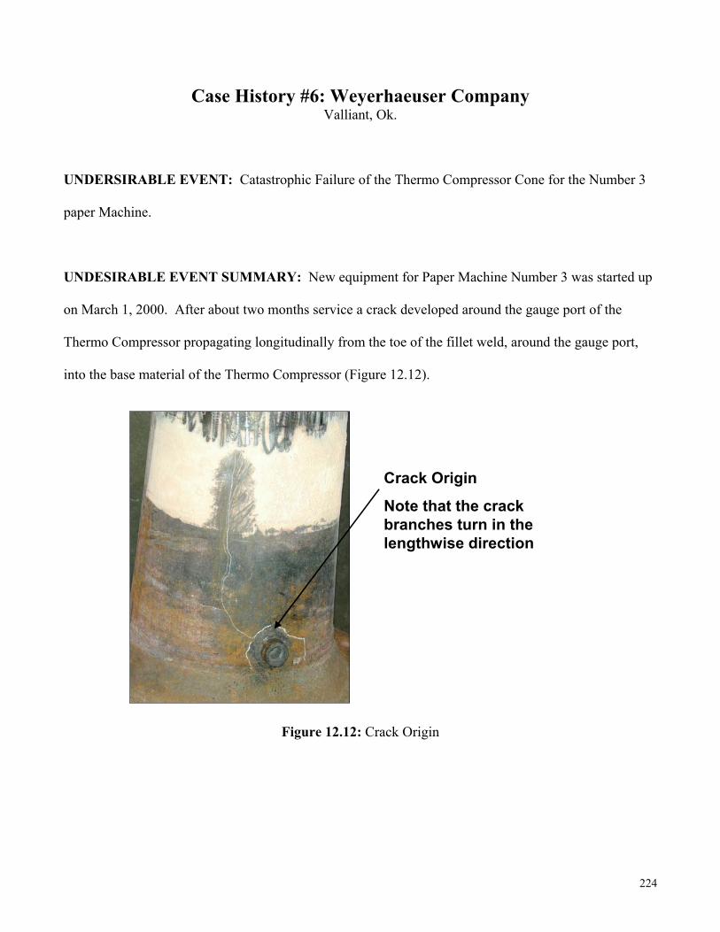
UNDESIRABLE EVENT SUMMARY: New equipment for Paper Machine Number 3 was started up
on March 1, 2000. After about two months service a crack developed around the gauge port of the
Thermo Compressor propagating longitudinally from the toe of the fillet weld, around the gauge port,
into the base material of the Thermo Compressor (Figure 12.12).
Figure 12.12: Crack Origin
Crack Origin
Note that the crack branches turn in the lengthwise direction

225
The Thermo Compressor was replaced with a like component. After two days service, a leak developed
at the longitudinal weld seam similar to the initial failure of the original Thermo Compressor (Figure
12.13).
Figure 12.13: Crack Along Longitudinal Seam of Thermo Compressor Cone
Thermo Compressor piping was visually inspected and subsequently analyzed because of the repeated
failures of the cone attachments and the component body. In doing so, a conventional piping analysis of
the design considering gravity, pressure and thermal growth forces showed that they were well within
the appropriate standards during normal operation, both with and without the Thermo Compressor in
service. Flaws in the pipe elbow of the Thermo Compressor were shown to progress into the piping wall
and were, therefore, quite serious. In addition, visual inspection of the weld area revealed defects that
contributed to the failure, including cracking and undercut (Figure 12.14).

226
Figure 12.14: Weld Defects in Thermo Compressor
Micro and Marco metallurgical examination of the weld area and heat affected zone uncovered addition
weld application and heat-treating defects that accounted for the stepping appearance of the cracks.
These examinations showed that the cracking followed a pattern that stepped from filler and base metal
inclusions (Figure 12.15) on a background tempered martensite base metal microstructure. In essence,
the crack approximated a pattern that represented flaws in the cone’s metallurgical microstructure, or the
path of least resistance throughout the filler and base metals of the Thermo Compressor’s cone shaped
body.
Martensit

227
Figure 12.15: Microstructure Defects
Visual examination of the weld’s crack cross sectional area showed evidence of fatigue contributing to
the failure of the Thermo Compressor Cone. As illustrated in (Figure 12.16), the arrow shows the
direction of the crack in the base metal. In addition, upon further close examination you can see circular
beach marks that fan out from the outside diameter of the cone. This combined with the ratchet marks
and a generally flat surface, are clear indications of a fatigue related failure demanding further
examination of the process.
To confirm fatigue as a contributor to the failure being analyzed, pipe wall flexure natural frequencies in
the piping that constitute the Thermo Compressor were identified with numerical methods and
confirmed through testing by plant personnel in the field under operating conditions. Here it was
determined that the natural frequency mode shapes were consistent with the location and orientation of
the cracks. Furthermore, all failure modes – attached cracking, loosening nuts, and cracked cone – are
consistent with the vibration induced from Thermo Compressor operation. The analytical conclusion of

228
the source of the fluctuating stress that was producing the fatigue failures was determined to be pipe
wall resonance, and that any coincidental acoustical resonance would synergistically magnify this
vibratory stress.
Figure 12.16: Fatigue Indications
The system analyzed for gravity, pressure and thermal stress is illustrated in (Figure 12.17). The
existing 65 psig steam header was limited in the model because it appeared to be unnecessary.
600# Steam Line
Location of where 600# steam line enters paper machine 3 building.

229
Figure 12.17: Piping System with 65 psig Steam Header Excluding Expansion Loop
Piping stress in and around the Thermo Compressor was determined to be low and there was seemingly
no correlation between the failures and piping stress from gravity, pressure and thermal loadings.
Vibration of the piping from which the Thermo Compressor cone is constructed was analyzed by
constructing a finite element computer model. Several natural frequencies were identified by dynamic
analysis. The natural frequency mode shape that occurs at 540 Hz (seen in Figure 12.18) shows a pipe
wall flexure that will produce the highest stress at precisely the location of an experienced crack. In
addition, the stress will also fluctuate, which is a necessary prerequisite for fatigue cracking.

230
Figure 12.18: Dynamic Finite Element Model of the Thermo Compressor Cone Showing a Fundamental
540 Hz Natural Frequency Pipe Wall Flexure Mode
The mode shape of (Figure 12.18) does not explain the initial crack branching into two cracks at the left
end. The mode shape of (Figure 12.19) shows the initial crack running into high fluctuating stress fields
that are at nominally 45 degrees on either side. The concave and convex areas alternate and provide the
fluctuating high stress fields necessary for the fatigue crack to advance in their directions.
Field measurement of the thicker cone showed a strong, undamped resonance at 780 Hz (46,000 cpm).
This coincides with the 777 Hz natural frequency of the pipe wall and explains the axial crack branching
to higher stress fields.
231
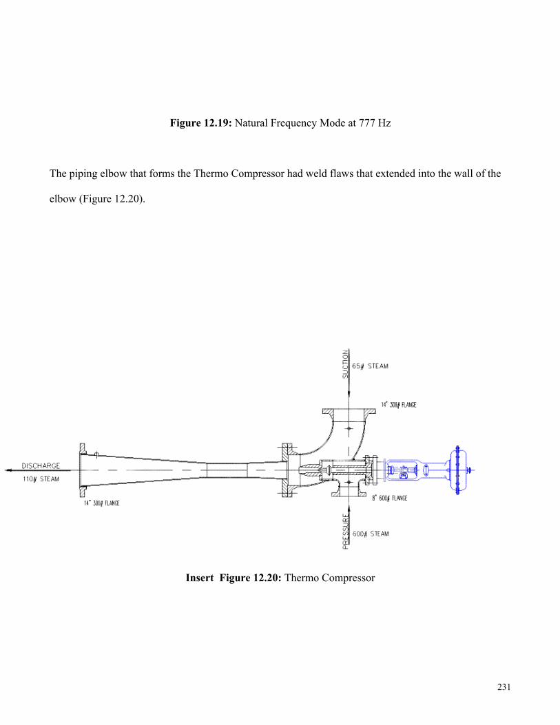
Figure 12.19: Natural Frequency Mode at 777 Hz
The piping elbow that forms the Thermo Compressor had weld flaws that extended into the wall of the
elbow (Figure 12.20).
Insert Figure 12.20: Thermo Compressor

232
Spring hangers were not properly adjusted because the basis for adjusting the support system is unclear.
The design calls for a cold setting, which is defined as total shutdown of the system, and a hot setting
that is obviously with the Thermo Compressor in operation.
It was observed that the mechanical fasteners for the Thermo Compressor flange near the spectacle blind
tie-in at the 65 psig header were loosening during operation due to high frequency piping vibrations.
The piping vibration and high Db noise levels from the Thermo Compressor are proportionately
amplified by excitation of the Thermo Compressor’s structural natural frequencies, especially in concert
with acoustical natural frequencies. This contributed to the creation of a steam leak due to gasket or
flange facing damage from previous operation with loose mechanical fasteners.
In general, static loads are acceptable by engineering code. Failure cannot be contributed to the static
loads induced by the system but by a fatigue mechanism. In addition, cracking failures on the Thermo
Compressor cone are related to pipe wall flexure resonance that is excited by normal Thermo
Compressor noise and vibration. Any coincidental acoustical natural frequencies, or their harmonics,
will accentuate vibratory stress.
The quality issues addressed earlier are significant to improving the life of the Thermo Compressor.
The margin of safety on the Thermo Compressor cone is unknown at this moment but can be determined
with an engineering assessment involving quantitative dynamic finite element analysis for stress with
fatigue considerations.
LINE-ITEM FROM MODIFIED FMEA

233
IDENTIFIED ROOT CAUSES
Physical Roots –
• Inadequate Supports for Thermo Compressor and Associated Piping
• Defective Thermo Compressor Base Metal
• Shop Welds Defective
• Condensate in The System Because of Control Valve Positioning on the 3rd and 4th Sections
• Incomplete Fusion
• Condensate Drains Impeded by Back Pressure in the System
Human Roots –
• Support System Design Error
• Thermo Compressor Not Specified Correctly
• Weld Application Error
• Design Deficiency of Condensate System
• Weld Technique Defective
• Running at Low/High Turn Down Ratios
Latent Roots –
• Inadequate Component Specifications for Support System
• Vendor Did Not Understand System Operating Environment
• Inadequate Specifications Supplied to Vendor for Thermo Compressor
• Original Design of Condensate Traps Inadequate for Service
• No Weld Procedure Specification

234
• Varying Operating Speeds to Meet Customer/Plant Requirements
• Did Not Follow Weld Procedure
• No Heat Treatment Requirements for Thermo Compressor
IMPLEMENTED CORRECTIVE ACTIONS
• New Specifications for Permanent Replacement Thermo Compressor Cone to Include:
Base Metal to be ½ inch Chrome Moly Material Instead of 5/16 inch Grade 516 Carbon
Steel
100% Radiographic Examination (x-ray) for all Welds
Delete Installation of Gauge Port From the Thermo Compressor
Stress Relieve the Assembly After Fabrication
• Require Thermo Compressor Manufacturer to Supply:
Welding Procedure Specification Used in Manufacturing
Radiographic Film Showing all Weld Passes per ASME B31.1 & ASME Section IX.
Stress Relieving Procedure per ASME Section IX

235
• Conduct an Engineering Assessment to Determine the Margin of Safety Against Thermo
Compressor Cone Failure – Methodology and Calculations Should Be Well Documented and
Open to Critical Review.
• Take Vibration Measurements for Amplitude and Frequency to Analyze Piping Both Before and
After Thermo Compressor Startup.
• Inspect for Steam Leaks at the Thermo Compressor Flanges During Startup and Periodically
During Operation.
• Modify Piping and Associated Supports for the Thermo Compressor in a Suspended Manner
with the Required Clearance Between the Piping and the Support Structure as Indicated by the
Outcome of the Stress Analysis.
• Adjust Spring Hangers and Note and Mark the Hangers to Reflect both Cold and Hot Positions.
• Install a Thermal Well in the 600# Steam to the Thermo Compressor to Monitor the Stability of
the Steam Temperature at the Point of Use.
• Reroute the Drainage of the Condensate Traps from the 65#, 600# and 120# Steam Piping to
Minimize the Effects of Backpressure and Steam/Water Hammer in the Condensate Drainage
System.
• Revise Operating Procedures to Limit the Thermo Compressor Turndown Ratio Between the 65#
inlet and outlet to be less than 1.80 to Mitigate Continuous Surging When Reaching the
Theoretical Limit of the Thermo Compressor.
EFFECT ON BOTTOM-LINE
TRACKING METRICS: Production Capacity Increase
BOTTOM-LINE RESULTS: 25% Increase in Production Capacity

236
CORRECTIVE ACTION TIME FRAMES: Approximately 4 Months
RCA TEAM STATISTICS:
Start Date: May 1, 2000 End Date: May 8, 2000
Estimated Cost to Conduct RCA: $41,476 Return on Investment: 1040%
RCA TEAM ACKNOWLEDGEMENTS:
Principal Analyst: Ronald L. Hughes
Title: Senior Reliability Consultant
Company: Reliability Center, Inc.
Core RCA Team Members:
Douglas Dretzke - Weyerhaeuser
Matt Connolly - Weyerhaeuser
Steven Breaux - Weyerhaeuser
Theron Henry - Weyerhaeuser
Joel White - Weyerhaeuser
Freddy Rodriguez - Kellogg Brown and Root
Additional RCA Team Comments: "Ron Hughes has done a tremendous job for Weyerhaeuser at Valliant and represented RCI in a highly professional manner. I believe that his contributions have advanced our skills and will enhance our future profitability.