Embed Size (px)
Citation preview
Product Data Sheet00813-0100-4021, Rev HA
March 2008 Rosemount 3144P
Rosemount 3144P Temperature Transmitter
• Sensor Drift Alert and Hot Backup® features
improve measurement reliability while the
Transmitter-Sensor Matching feature
improves temperature measurement accuracy
• Statistical Process Monitoring (SPM) and
Thermocouple Diagnostics provide improved
visibility into process conditions and sensor
loops.
• Communicate using either 4-20 mA/HART® or
FOUNDATION™ fieldbus protocol
• The integral LCD Display (optional)
conveniently displays sensor values and
transmitter diagnostics information
• Capable of single-sensor and dual-sensor
inputs. Differential and average temperature
measurement increases system flexibility
• Dual-compartment housing provides the
highest reliability in harsh industrial
environments
• Safety certified to IEC 61508
www.ro
Content
The Ultimate Temperature Transmitter for Critical Control and Safety Applications . . . . . . . .page 2
Specifications
HART and FOUNDATION Fieldbus Specifications . . . . . . . . . . . . . . . . . . . . . . . . . . . . . . page 3
HART / 4-20 mA Specifications . . . . . . . . . . . . . . . . . . . . . . . . . . . . . . . . . . . . . . . . . . page 6
FOUNDATION Fieldbus Specifications . . . . . . . . . . . . . . . . . . . . . . . . . . . . . . . . . . . . . . . page 7
Product Certifications . . . . . . . . . . . . . . . . . . . . . . . . . . . . . . . . . . . . . . . . . . . . . . . . . . . . . . page 9
Dimensional Drawings. . . . . . . . . . . . . . . . . . . . . . . . . . . . . . . . . . . . . . . . . . . . . . . . . . . . . page 13
Ordering Information . . . . . . . . . . . . . . . . . . . . . . . . . . . . . . . . . . . . . . . . . . . . . . . . . . . . . . page 16
Configuration Data Sheets
HART® / 4–20 mA / and Safety Certified transmitter. . . . . . . . . . . . . . . . . . . . . . . . . . page 20
Foundation™ Fieldbus transmitter . . . . . . . . . . . . . . . . . . . . . . . . . . . . . . . . . . . . . . . . page 22
semount.com
Product Data Sheet00813-0100-4021, Rev HA
March 2008Rosemount 3144P
2
The Ultimate Temperature Transmitter for
Critical Control and Safety ApplicationsThe Rosemount 3144P Temperature Transmitter provides superior accuracy, stability, and reliability – making it the
industry-leading temperature transmitter used in critical control and safety applications. The 3144P can be ordered with either
4–20 mA/HART or a completely digital FOUNDATION fieldbus protocol. It has the capability to accept either single-sensor or
dual-sensor inputs. This dual-sensor input capability allows the transmitter to accept simultaneous input from two independent
sensors, enabling measurement of differential temperatures, averaging temperature, or redundant temperature measurement.
The transmitter can be configured for a variety of sensor inputs: RTD, thermocouple, millivolt, or ohm. The 3144P (HART) is
approved for use in Safety Instrumented Systems (third party validated metrics are available for the 3144P. Testing done per
IEC 61508 for Safety Instrumented Systems).
Best in Class Accuracy and ReliabilityThe transmitter provides industry-leading five-year stability,
which reduces maintenance costs. The Transmitter-Sensor
Matching feature eliminates interchangeability error, which
improves accuracy by 75%. Sensor Drift Alert enables
continuous monitoring of the differential temperature for
two sensors. When one sensor drifts, the differential of the
sensors will increase. If this difference exceeds defined
limits, the user is alerted of an unreliable measurement.
The Hot Backup feature can reduce the risk of losing
important temperature measurements by 80% when the
measurement automatically switches to the backup sensor
if the primary sensor fails.
Reliable Transmitter PerformanceMeeting the NAMUR NE 21 recommendations, the 3144P
ensures top transmitter performance in harsh EMC
environments. In addition, the 3144P HART transmitter
meets NAMUR NE 43 and NE 89 recommendations.
FOUNDATION Fieldbus and HART ProtocolsHigh performance and advanced diagnostics are available
with HART or FOUNDATION fieldbus communication. These
transmitters offer diagnostics that provide continuous
measurement status (good, bad, or uncertain), as well as
sensor failure indication. Both transmitters provide
performance information to AMS.
Integral LCD DisplayLocal indication of temperature measurement and
diagnostics provides immediate and accurate verification of
process conditions.
Measurement FlexibilityThe 3144P is capable of single-sensor or dual-sensor
input. This also allows for configuration of differential or
average temperature measurements.
Designed for Harsh EnvironmentsThe 3144P is designed with a dual-compartment housing
that provides the highest reliability in harsh environments.
The dual-compartment housing provides isolation between
the electronics and terminal compartments. The large
terminal block allows for easier wire installation. Enhanced
EMI rejection and filtering result in unmatched stability in
process measurement.
Certified for use in SIS ApplicationsThe 3144P is certified to IEC61508 for non-redundant use
in SIL 1 and 2 Safety Instrumented Systems and redundant
use in SIL 3 Safety Instrumented Systems. In allowable
installations, the 3144P HART electronics can be upgraded
to safety certified electronics.
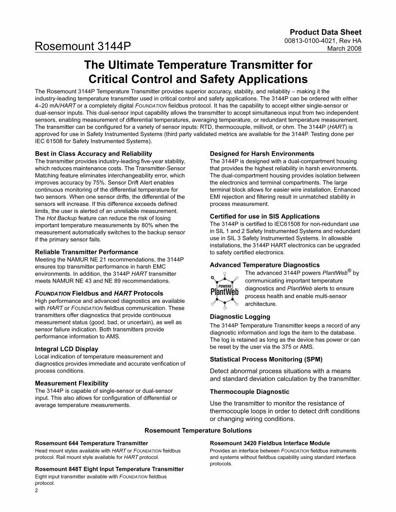
Advanced Temperature Diagnostics
The advanced 3144P powers PlantWeb® by
communicating important temperature
diagnostics and PlantWeb alerts to ensure
process health and enable multi-sensor
architecture.
Diagnostic Logging
The 3144P Temperature Transmitter keeps a record of any
diagnostic information and logs the item to the database.
The log is retained as long as the device has power or can
be reset by the user via the 375 or AMS.
Statistical Process Monitoring (SPM)
Detect abnormal process situations with a means
and standard deviation calculation by the transmitter.
Thermocouple Diagnostic
Use the transmitter to monitor the resistance of
thermocouple loops in order to detect drift conditions
or changing wiring conditions.
Rosemount Temperature Solutions
Rosemount 644 Temperature Transmitter
Head mount styles available with HART or FOUNDATION fieldbus
protocol. Rail mount style available for HART protocol.
Rosemount 848T Eight Input Temperature Transmitter
Eight input transmitter available with FOUNDATION fieldbus
protocol.
Rosemount 3420 Fieldbus Interface Module
Provides an interface between FOUNDATION fieldbus instruments
and systems without fieldbus capability using standard interface
protocols.
Product Data Sheet00813-0100-4021, Rev HA
March 2008 Rosemount 3144P
HART
an
d
FOUNDATIO
N F
ield
bu
s
Rosemount 248 Temperature Transmitter
Head mount style (DIN B) and Rail mount style with HART
protocol and complete temperature assembly.
Rosemount sensors, thermowells, and extensions
Rosemount has a broad offering of RTD and thermocouples that
are designed to meet plant requirements.
Rosemount 148 Temperature Transmitter
Head mount style (DIN B) PC-programmable transmitter
Specifications
HART® AND FOUNDATION
™ FIELDBUS
Functional
InputsUser-selectable. See “Accuracy” on page 4 for sensor options.
Output2-wire device with either 4–20 mA/HART, linear with temperature
or input, or completely digital output with FOUNDATION fieldbus
communication (ITK 4.6 compliant).
IsolationInput/output isolation tested up to 500 V ac (707 V dc) at
50/60 Hz.
Humidity Limits0–100% relative humidity.
Update TimeApproximately 0.5 seconds for a single sensor (1 second for
dual sensors).
Physical
Conduit ConnectionsThe standard field mount housing has ½–14 NPT conduit entries.
Additional conduit entry type are available, including PG13.5
(PG11), M20 X 1.5 (CM20), or JIS G ½. When any of these
additional entry types are ordered, adapters are placed in the
standard field housing so these alternative conduit types fit
correctly. See “Dimensional Drawings” on page 13 for dimensions.
Materials of ConstructionElectronics Housing
• Low-copper aluminum or CF-8M (cast version of 316
Stainless Steel)
Paint
• Polyurethane
Cover O-ringsBuna-N
MountingTransmitters may be attached directly to the sensor. Optional
mounting brackets (codes B4 and B5) allow for remote mounting.
See “Optional Transmitter Mounting Brackets” on page 14.
Weight
Enclosure RatingsNEMA 4X, CSA Enclosure Type 4X, IP66, and IP68.
Stability • RTDs - ±0.1% of reading or 0.1 °C, whichever is greater, for
24 months.
• Thermocouples - ±0.1% of reading or 0.1 °C, whichever is
greater, for 12 months.
5 Year Stability• RTDs - ±0.25% of reading or 0.25 °C, whichever is greater, for
5 years.
• Thermocouples - ±0.5% of reading or 0.5 °C, whichever is
greater, for 5 years.
Vibration EffectTested to the following with no effect on performance:
Self CalibrationThe analog-to-digital measurement circuitry automatically
self-calibrates for each temperature update by comparing the
dynamic measurement to extremely stable and accurate internal
reference elements.
RFI EffectWorst case RFI effect is equivalent to the transmitter’s nominal
accuracy specification, according to Table on page 4, when tested
in accordance with IEC 61000-4-3, 30 V/m (HART) / 20 V/m
(HART T/C) /10 V/m (FOUNDATION fieldbus), 80 to 1000 MHz, with
unshielded cable.
CE Electromagnetic Compatibility Compliance TestingThe 3144P meets or exceeds all requirements listed under IEC
61326: Amendment 1, 1998.
Aluminum(1)
(1) Add 0.5 lb (0.2 kg) for meter or 1.0 lb (0.5 kg) for bracket options.
Stainless Steel(1)
3.1 lb (1.4 kg) 7.8 lb (3.5 kg)
Frequency Acceleration
10–60 Hz 0.21 mm peak displacement
60–2000 Hz 3 g
3
Product Data Sheet00813-0100-4021, Rev HA
March 2008Rosemount 3144P
HART
an
d
FOUNDATIO
N F
ield
bu
s
External Ground Screw Assembly
The external ground screw assembly can be ordered by specifying
code G1 when an enclosure is specified. However, some
approvals include the ground screw assembly in the transmitter
shipment, hence it is not necessary to order code G1. The table
below identifies which approval options include the external
ground screw assembly.
Hardware Tag• No charge
• 2 lines of 28 characters (56 characters total)
• Tags are stainless steel
• Permanently attached to transmitter
• Character height is 1/16-in. (1.6mm)
• A wire-on tag is available upon request. 5 lines of 12
characters (60 characters total)
Software Tag• HART transmitter can store up to 8 characters. FOUNDATION
fieldbus transmitters can store up to 32 characters.
• Can be ordered with different software and hardware tags.
• If no software tag characters are specified, the first 8
characters of the hardware tag are the default.
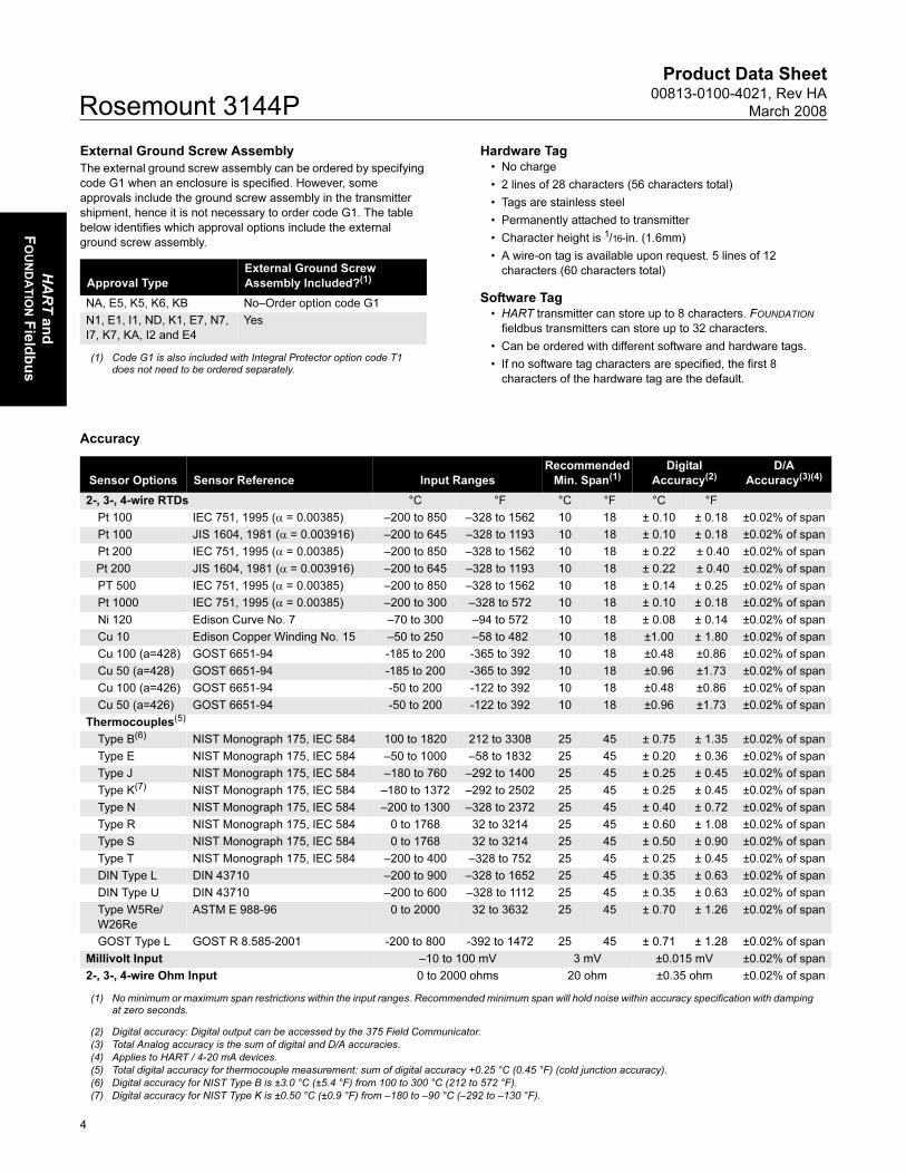
Accuracy
Approval Type
External Ground Screw
Assembly Included?(1)
(1) Code G1 is also included with Integral Protector option code T1 does not need to be ordered separately.
NA, E5, K5, K6, KB No–Order option code G1
N1, E1, I1, ND, K1, E7, N7,
I7, K7, KA, I2 and E4
Yes
Sensor Options Sensor Reference Input Ranges
Recommended
Min. Span(1)
(1) No minimum or maximum span restrictions within the input ranges. Recommended minimum span will hold noise within accuracy specification with damping at zero seconds.
Digital
Accuracy(2)
(2) Digital accuracy: Digital output can be accessed by the 375 Field Communicator.
D/A
Accuracy(3)(4)
(3) Total Analog accuracy is the sum of digital and D/A accuracies.
(4) Applies to HART / 4-20 mA devices.
2-, 3-, 4-wire RTDs °C °F °C °F °C °F
Pt 100 IEC 751, 1995 (α = 0.00385) –200 to 850 –328 to 1562 10 18 ± 0.10 ± 0.18 ±0.02% of span
Pt 100 JIS 1604, 1981 (α = 0.003916) –200 to 645 –328 to 1193 10 18 ± 0.10 ± 0.18 ±0.02% of span
Pt 200 IEC 751, 1995 (α = 0.00385) –200 to 850 –328 to 1562 10 18 ± 0.22 ± 0.40 ±0.02% of span
Pt 200 JIS 1604, 1981 (α = 0.003916) –200 to 645 –328 to 1193 10 18 ± 0.22 ± 0.40 ±0.02% of span
PT 500 IEC 751, 1995 (α = 0.00385) –200 to 850 –328 to 1562 10 18 ± 0.14 ± 0.25 ±0.02% of span
Pt 1000 IEC 751, 1995 (α = 0.00385) –200 to 300 –328 to 572 10 18 ± 0.10 ± 0.18 ±0.02% of span
Ni 120 Edison Curve No. 7 –70 to 300 –94 to 572 10 18 ± 0.08 ± 0.14 ±0.02% of span
Cu 10 Edison Copper Winding No. 15 –50 to 250 –58 to 482 10 18 ±1.00 ± 1.80 ±0.02% of span
Cu 100 (a=428) GOST 6651-94 -185 to 200 -365 to 392 10 18 ±0.48 ±0.86 ±0.02% of span
Cu 50 (a=428) GOST 6651-94 -185 to 200 -365 to 392 10 18 ±0.96 ±1.73 ±0.02% of span
Cu 100 (a=426) GOST 6651-94 -50 to 200 -122 to 392 10 18 ±0.48 ±0.86 ±0.02% of span
Cu 50 (a=426) GOST 6651-94 -50 to 200 -122 to 392 10 18 ±0.96 ±1.73 ±0.02% of span
Thermocouples(5)
(5) Total digital accuracy for thermocouple measurement: sum of digital accuracy +0.25 °C (0.45 °F) (cold junction accuracy).
Type B(6)
(6) Digital accuracy for NIST Type B is ±3.0 °C (±5.4 °F) from 100 to 300 °C (212 to 572 °F).
NIST Monograph 175, IEC 584 100 to 1820 212 to 3308 25 45 ± 0.75 ± 1.35 ±0.02% of span
Type E NIST Monograph 175, IEC 584 –50 to 1000 –58 to 1832 25 45 ± 0.20 ± 0.36 ±0.02% of span
Type J NIST Monograph 175, IEC 584 –180 to 760 –292 to 1400 25 45 ± 0.25 ± 0.45 ±0.02% of span
Type K(7)
(7) Digital accuracy for NIST Type K is ±0.50 °C (±0.9 °F) from –180 to –90 °C (–292 to –130 °F).
NIST Monograph 175, IEC 584 –180 to 1372 –292 to 2502 25 45 ± 0.25 ± 0.45 ±0.02% of span
Type N NIST Monograph 175, IEC 584 –200 to 1300 –328 to 2372 25 45 ± 0.40 ± 0.72 ±0.02% of span
Type R NIST Monograph 175, IEC 584 0 to 1768 32 to 3214 25 45 ± 0.60 ± 1.08 ±0.02% of span
Type S NIST Monograph 175, IEC 584 0 to 1768 32 to 3214 25 45 ± 0.50 ± 0.90 ±0.02% of span
Type T NIST Monograph 175, IEC 584 –200 to 400 –328 to 752 25 45 ± 0.25 ± 0.45 ±0.02% of span
DIN Type L DIN 43710 –200 to 900 –328 to 1652 25 45 ± 0.35 ± 0.63 ±0.02% of span
DIN Type U DIN 43710 –200 to 600 –328 to 1112 25 45 ± 0.35 ± 0.63 ±0.02% of span
Type W5Re/
W26Re
ASTM E 988-96 0 to 2000 32 to 3632 25 45 ± 0.70 ± 1.26 ±0.02% of span
GOST Type L GOST R 8.585-2001 -200 to 800 -392 to 1472 25 45 ± 0.71 ± 1.28 ±0.02% of span
Millivolt Input –10 to 100 mV 3 mV ±0.015 mV ±0.02% of span
2-, 3-, 4-wire Ohm Input 0 to 2000 ohms 20 ohm ±0.35 ohm ±0.02% of span
4
Product Data Sheet00813-0100-4021, Rev HA
March 2008 Rosemount 3144P
HART
an
d
FOUNDATIO
N F
ield
bu
s
Reference Accuracy Example (HART only)
When using a Pt 100 (α = 0.00385) sensor input with a 0 to 100 °C
span: Digital Accuracy would be ±0.10 °C, D/A accuracy would be
±0.02% of 100 °C or ±0.02 °C, Total = ±0.12 °C.
Differential Capability Exists Between Any Two Sensor
Types (dual-sensor option)
For all differential configurations, the input range is X to Y where:
• X = Sensor 1 minimum – Sensor 2 maximum and
• Y = Sensor 1 maximum – Sensor 2 minimum.
Digital Accuracy for Differential Configurations
(dual-sensor option, HART only)
• Sensor types are similar (e.g., both RTDs or both T/Cs):
Digital Accuracy = 1.5 times worst case accuracy of either
sensor type.
• Sensor types are dissimilar (e.g., one RTD, one T/C): Digital
Accuracy = Sensor 1 Accuracy + Sensor 2 Accuracy.
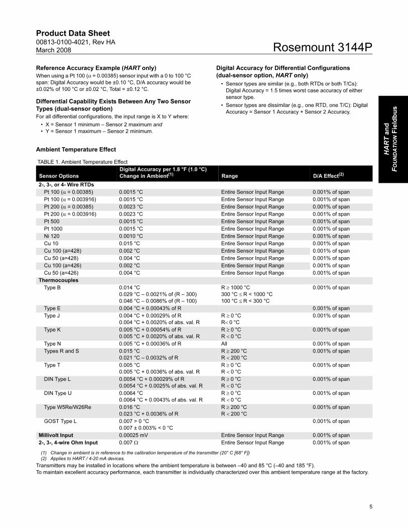
Ambient Temperature Effect
TABLE 1. Ambient Temperature Effect
Transmitters may be installed in locations where the ambient temperature is between –40 and 85 °C (–40 and 185 °F).
To maintain excellent accuracy performance, each transmitter is individually characterized over this ambient temperature range at the factory.
Sensor Options
Digital Accuracy per 1.8 °F (1.0 °C)
Change in Ambient(1)
(1) Change in ambient is in reference to the calibration temperature of the transmitter (20° C [68° F])
Range D/A Effect(2)
(2) Applies to HART / 4-20 mA devices.
2-, 3-, or 4- Wire RTDs
Pt 100 (α = 0.00385) 0.0015 °C Entire Sensor Input Range 0.001% of span
Pt 100 (α = 0.003916) 0.0015 °C Entire Sensor Input Range 0.001% of span
Pt 200 (α = 0.00385) 0.0023 °C Entire Sensor Input Range 0.001% of span
Pt 200 (α = 0.003916) 0.0023 °C Entire Sensor Input Range 0.001% of span
Pt 500 0.0015 °C Entire Sensor Input Range 0.001% of span
Pt 1000 0.0015 °C Entire Sensor Input Range 0.001% of span
Ni 120 0.0010 °C Entire Sensor Input Range 0.001% of span
Cu 10 0.015 °C Entire Sensor Input Range 0.001% of span
Cu 100 (a=428) 0.002 °C Entire Sensor Input Range 0.001% of span
Cu 50 (a=428) 0.004 °C Entire Sensor Input Range 0.001% of span
Cu 100 (a=426) 0.002 °C Entire Sensor Input Range 0.001% of span
Cu 50 (a=426) 0.004 °C Entire Sensor Input Range 0.001% of span
Thermocouples
Type B 0.014 °C
0.029 °C – 0.0021% of (R – 300)
0.046 °C – 0.0086% of (R – 100)
R ≥ 1000 °C
300 °C ≤ R < 1000 °C
100 °C ≤ R < 300 °C
0.001% of span
Type E 0.004 °C + 0.00043% of R 0.001% of span
Type J 0.004 °C + 0.00029% of R
0.004 °C + 0.0020% of abs. val. R
R ≥ 0 °C
R< 0 °C
0.001% of span
Type K 0.005 °C + 0.00054% of R
0.005 °C + 0.0020% of abs. val. R
R ≥ 0 °C
R < 0 °C
0.001% of span
Type N 0.005 °C + 0.00036% of R All 0.001% of span
Types R and S 0.015 °C
0.021 °C – 0.0032% of R
R ≥ 200 °C
R < 200 °C
0.001% of span
Type T 0.005 °C
0.005 °C + 0.0036% of abs. val. R
R ≥ 0 °C
R < 0 °C
0.001% of span
DIN Type L 0.0054 °C + 0.00029% of R
0.0054 °C + 0.0025% of abs. val. R
R ≥ 0 °C
R < 0 °C
0.001% of span
DIN Type U 0.0064 °C
0.0064 °C + 0.0043% of abs. val. R
R ≥ 0 °C
R < 0 °C
0.001% of span
Type W5Re/W26Re 0.016 °C
0.023 °C + 0.0036% of R
R ≥ 200 °C
R < 200 °C
0.001% of span
GOST Type L 0.007 > 0 °C
0.007 ± 0.003% < 0 °C
0.001% of span
Millivolt Input 0.00025 mV Entire Sensor Input Range 0.001% of span
2-, 3-, 4-wire Ohm Input 0.007 Ω Entire Sensor Input Range 0.001% of span
5
Product Data Sheet00813-0100-4021, Rev HA
March 2008Rosemount 3144P
HART
4–20 m
A
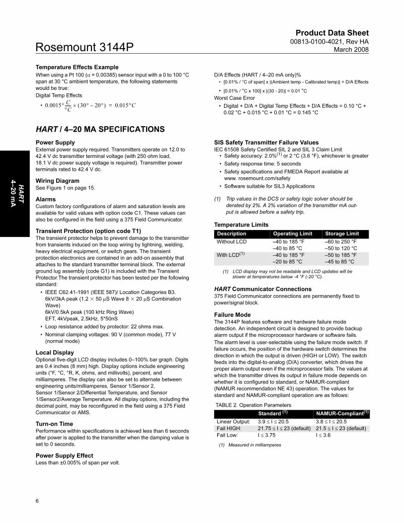
Temperature Effects Example
When using a Pt 100 (α = 0.00385) sensor input with a 0 to 100 °C
span at 30 °C ambient temperature, the following statements
would be true:
Digital Temp Effects
•
D/A Effects (HART / 4–20 mA only)%
• [0.01% / °C of span] x |(Ambient temp - Calibrated temp)| = D/A Effects
• [0.01% / °C x 100] x |(30 - 20)| = 0.01 °C
Worst Case Error
• Digital + D/A + Digital Temp Effects + D/A Effects = 0.10 °C +
0.02 °C + 0.015 °C + 0.01 °C = 0.145 °C
HART / 4–20 MA SPECIFICATIONS
Power SupplyExternal power supply required. Transmitters operate on 12.0 to
42.4 V dc transmitter terminal voltage (with 250 ohm load,
18.1 V dc power supply voltage is required). Transmitter power
terminals rated to 42.4 V dc.
Wiring DiagramSee Figure 1 on page 15.
AlarmsCustom factory configurations of alarm and saturation levels are
available for valid values with option code C1. These values can
also be configured in the field using a 375 Field Communicator.
Transient Protection (option code T1)The transient protector helps to prevent damage to the transmitter
from transients induced on the loop wiring by lightning, welding,
heavy electrical equipment, or switch gears. The transient
protection electronics are contained in an add-on assembly that
attaches to the standard transmitter terminal block. The external
ground lug assembly (code G1) is included with the Transient
Protector.The transient protector has been tested per the following
standard:
• IEEE C62.41-1991 (IEEE 587)/ Location Categories B3.
6kV/3kA peak (1.2 � 50 μS Wave 8 � 20 μS Combination
Wave)
6kV/0.5kA peak (100 kHz Ring Wave)
EFT, 4kVpeak, 2.5kHz, 5*50nS
• Loop resistance added by protector: 22 ohms max.
• Nominal clamping voltages: 90 V (common mode), 77 V
(normal mode)
Local DisplayOptional five-digit LCD display includes 0–100% bar graph. Digits
are 0.4 inches (8 mm) high. Display options include engineering
units (°F, °C, °R, K, ohms, and millivolts), percent, and
milliamperes. The display can also be set to alternate between
engineering units/milliamperes, Sensor 1/Sensor 2,
Sensor 1/Sensor 2/Differential Temperature, and Sensor
1/Sensor2/Average Temperature. All display options, including the
decimal point, may be reconfigured in the field using a 375 Field
Communicator or AMS.
Turn-on TimePerformance within specifications is achieved less than 6 seconds
after power is applied to the transmitter when the damping value is
set to 0 seconds.
Power Supply EffectLess than ±0.005% of span per volt.
SIS Safety Transmitter Failure ValuesIEC 61508 Safety Certified SIL 2 and SIL 3 Claim Limit
Temperature Limits
HART Communicator Connections375 Field Communicator connections are permanently fixed to
power/signal block.
Failure ModeThe 3144P features software and hardware failure mode
detection. An independent circuit is designed to provide backup
alarm output if the microprocessor hardware or software fails.
The alarm level is user-selectable using the failure mode switch. If
failure occurs, the position of the hardware switch determines the
direction in which the output is driven (HIGH or LOW). The switch
feeds into the digital-to-analog (D/A) converter, which drives the
proper alarm output even if the microprocessor fails. The values at
which the transmitter drives its output in failure mode depends on
whether it is configured to standard, or NAMUR-compliant
(NAMUR recommendation NE 43) operation. The values for
standard and NAMUR-compliant operation are as follows:
TABLE 2. Operation Parameters
0.0015°C
°C------ 30° 20°–( )× 0.015°C=
• Safety accuracy: 2.0%(1) or 2 °C (3.6 °F), whichever is greater
• Safety response time: 5 seconds
• Safety specifications and FMEDA Report available at
www. rosemount.com/safety
• Software suitable for SIL3 Applications
(1) Trip values in the DCS or safety logic solver should be
derated by 2%. A 2% variation of the transmitter mA out-
put is allowed before a safety trip.
Description Operating Limit Storage Limit
Without LCD –40 to 185 °F
–40 to 85 °C
–60 to 250 °F
–50 to 120 °C
With LCD(1)
(1) LCD display may not be readable and LCD updates will be slower at temperatures below -4 °F (-20 °C).
–40 to 185 °F
–20 to 85 °C
–50 to 185 °F
–45 to 85 °C
Standard (1)
(1) Measured in milliamperes
NAMUR-Compliant(1)
Linear Output: 3.9 ≤ I ≤ 20.5 3.8 ≤ I ≤ 20.5
Fail HIGH: 21.75 ≤ I ≤ 23 (default) 21.5 ≤ I ≤ 23 (default)
Fail Low: I ≤ 3.75 I ≤ 3.6
6
Product Data Sheet00813-0100-4021, Rev HA
March 2008 Rosemount 3144P
FOUNDATIO
N
Fie
ldb
us
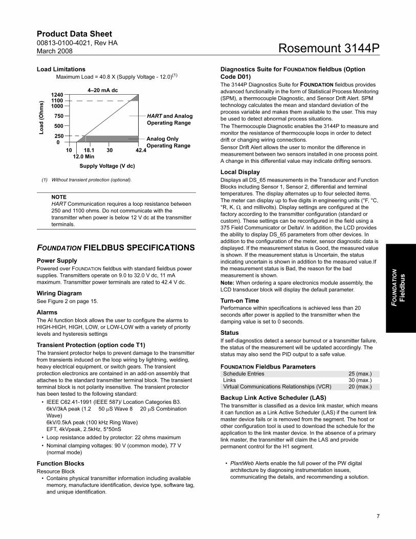
Load Limitations
NOTE
HART Communication requires a loop resistance between
250 and 1100 ohms. Do not communicate with the
transmitter when power is below 12 V dc at the transmitter
terminals.
FOUNDATION FIELDBUS SPECIFICATIONS
Power Supply
Powered over FOUNDATION fieldbus with standard fieldbus power
supplies. Transmitters operate on 9.0 to 32.0 V dc, 11 mA
maximum. Transmitter power terminals are rated to 42.4 V dc.
Wiring Diagram
See Figure 2 on page 15.
Alarms
The AI function block allows the user to configure the alarms to
HIGH-HIGH, HIGH, LOW, or LOW-LOW with a variety of priority
levels and hysteresis settings
Transient Protection (option code T1)
The transient protector helps to prevent damage to the transmitter
from transients induced on the loop wiring by lightning, welding,
heavy electrical equipment, or switch gears. The transient
protection electronics are contained in an add-on assembly that
attaches to the standard transmitter terminal block. The transient
terminal block is not polarity insensitive. The transient protector
has been tested to the following standard:
• IEEE C62.41-1991 (IEEE 587)/ Location Categories B3.
6kV/3kA peak (1.2 50 μS Wave 8 20 μS Combination
Wave)
6kV/0.5kA peak (100 kHz Ring Wave)
EFT, 4kVpeak, 2.5kHz, 5*50nS
• Loop resistance added by protector: 22 ohms maximum
• Nominal clamping voltages: 90 V (common mode), 77 V
(normal mode)
Diagnostics Suite for FOUNDATION fieldbus (Option
Code D01)
The 3144P Diagnostics Suite for FOUNDATION fieldbus provides
advanced functionality in the form of Statistical Process Monitoring
(SPM), a thermocouple Diagnostic, and Sensor Drift Alert. SPM
technology calculates the mean and standard deviation of the
process variable and makes them available to the user. This may
be used to detect abnormal process situations.
The Thermocouple Diagnostic enables the 3144P to measure and
monitor the resistance of thermocouple loops in order to detect
drift or changing wiring connections.
Sensor Drift Alert allows the user to monitor the difference in
measurement between two sensors installed in one process point.
A change in this differential value may indicate drifting sensors.
Local Display
Displays all DS_65 measurements in the Transducer and Function
Blocks including Sensor 1, Sensor 2, differential and terminal
temperatures. The display alternates up to four selected items.
The meter can display up to five digits in engineering units (°F, °C,
°R, K, Ω, and millivolts). Display settings are configured at the
factory according to the transmitter configuration (standard or
custom). These settings can be reconfigured in the field using a
375 Field Communicator or DeltaV. In addition, the LCD provides
the ability to display DS_65 parameters from other devices. In
addition to the configuration of the meter, sensor diagnostic data is
displayed. If the measurement status is Good, the measured value
is shown. If the measurement status is Uncertain, the status
indicating uncertain is shown in addition to the measured value.If
the measurement status is Bad, the reason for the bad
measurement is shown.
Note: When ordering a spare electronics module assembly, the
LCD transducer block will display the default parameter.
Turn-on TimePerformance within specifications is achieved less than 20
seconds after power is applied to the transmitter when the
damping value is set to 0 seconds.
Status
If self-diagnostics detect a sensor burnout or a transmitter failure,
the status of the measurement will be updated accordingly. The
status may also send the PID output to a safe value.
FOUNDATION Fieldbus Parameters
Backup Link Active Scheduler (LAS)
The transmitter is classified as a device link master, which means
it can function as a Link Active Scheduler (LAS) if the current link
master device fails or is removed from the segment. The host or
other configuration tool is used to download the schedule for the
application to the link master device. In the absence of a primary
link master, the transmitter will claim the LAS and provide
permanent control for the H1 segment.
Function Blocks
Resource Block
• Contains physical transmitter information including available
memory, manufacture identification, device type, software tag,
and unique identification.
• PlantWeb Alerts enable the full power of the PW digital
architecture by diagnosing instrumentation issues,
communicating the details, and recommending a solution.
Maximum Load = 40.8 X (Supply Voltage - 12.0)(1)
(1) Without transient protection (optional).
1240
1000
750
2500
1012.0 Min
18.1 30 42.4
Supply Voltage (V dc)
HART and Analog
Operating Range
4–20 mA dc
Lo
ad
(O
hm
s)
500
1100
Analog Only
Operating Range
Schedule Entries 25 (max.)
Links 30 (max.)
Virtual Communications Relationships (VCR) 20 (max.)
7

Product Data Sheet00813-0100-4021, Rev HA
March 2008Rosemount 3144P
HART
4–20 m
A
Transducer Block
• Contains the actual temperature measurement data, including
sensor 1, sensor 2, and terminal temperature.
• Includes information about sensor type and configuration,
engineering units, linearization, range, damping, and
diagnostics.
LCD Block (when an LCD display is used)
• Configures the local display.
Analog Input (AI)
• Processes the measurement and makes it available on the
fieldbus segment.
• Allows filtering, engineering unit, and alarm changes.
PID Block (provides control functionality)
• Performs single loop, cascade, or feedforward control in the
field.
Block Execution Time
Resource –
Transducer –
LCD Block –
Advanced Diagnostics –
Analog Input 1, 2, 3 60 milliseconds
PID 1 and 2 with Autotune 90 milliseconds
Input Selector 65 milliseconds
Signal Characterizer 45 milliseconds
Arithmetic 60 milliseconds
Output Splitter 60 milliseconds
8
Product Data Sheet00813-0100-4021, Rev HA
March 2008 Rosemount 3144P
HART
4–20 m
A
Product Certifications
ROSEMOUNT 3144P WITH HART / 4–20 mA
Approved Manufacturing LocationsRosemount Inc. – Chanhassen, Minnesota, USA
Rosemount Temperature GmbH – Germany
Emerson Process Management Asia Pacific – Singapore
European Union Directive InformationThe EC declaration of conformity for all applicable European
Directives for this product can be found on the Rosemount website
at www.rosemount.com. A hard copy may be obtained by
contacting an Emerson Process Management representative.
ATEX Directive (94/9/EC)Rosemount Inc. complies with the ATEX Directive.
Electro Magnetic Compatibility (EMC)
(89/336/EEC)EN 50081-1: 1992; EN 50082-2:1995; EN 61326-A1+A2+A3:1997 – Industrial
Hazardous Locations InstallationsNorth American Certifications
Factory Mutual (FM) Approvals
I5 FM Intrinsic Safety and Non-incendive:
Intrinsically Safe for Class I/II/III, Division 1, Groups A, B, C,
D, E, F, and G.
Temperature codes: T4A (Tamb = – 60 to 60 °C)
T5 (Tamb = – 60 to 50°C)
Zone Marking: Class I, Zone 0, AEx ia IIC
T4 (Tamb = – 50 to 60 °C)
Intrinsically Safe when installed in accordance with control
drawing 03144-0321.
Non-incendive for use in Class I, Division 2, Groups A, B, C,
and D. Suitable for use in Class II / III, Division 2, Groups F
and G. Non-incendive when installed in accordance with
Rosemount drawings 03144-0321.
Temperature codes: T6 (Tamb = – 60 to 60 °C),
T5 (Tamb = – 60 to 85°C)
E5 Explosion Proof for Class I, Division 1, Groups A, B, C, D.
Dust Ignition-Proof for use in Class II/III, Division 1, Groups
E, F, and G. Explosion-Proof and Dust Ignition-Proof when
installed in accordance with Rosemount drawing
03144-0320. Indoor and outdoor use. NEMA Type 4X.
Temperature code: T5 (Tamb = – 50 to 85 °C)
NOTE
For Group A, seal all conduits within 18 inches of enclosure;
otherwise, conduit seal not required for compliance with
NEC 501-15(A)(1).
Non-incendive for use in Class I, Division 2, Groups A, B, C,
and D. Suitable for use in Class II/III, Division 2, Groups F
and G. Non-incendive when installed in accordance with
Rosemount drawing 03144-0321.
Temperature codes: T5 (Tamb = – 60 to 85 °C),
T6 (Tamb = – 60 to 60°C)
Canadian Standards Association (CSA) Approvals
I6 CSA Intrinsic Safety and Division 2
Intrinsically Safe for Class I, Division 1, Groups A, B, C, and
D; Class II, Division 1, Groups E, F, and G; Class III, Division
1; Suitable for Class I, Division 2, Groups A, B, C, and D.
Intrinsically Safe and Division 2 when installed per
Rosemount drawing 03144–0322.
K6 Combination of I6 and the following:
Explosion Proof for Class I, Division 1, Groups A, B, C, and
D; Class II, Division 1, Groups E, F, and G; Class III, Division
1 hazardous locations when installed per drawing
03144-0302. Factory sealed.
European Certifications
E1 ATEX Flameproof Approval (Zone 1)
Certificate Number: KEMA01ATEX2181
ATEX Category Marking II 2 G
EEx d IIC T6 (Tamb = –40 to 70 °C)
EEx d IIC T5 (Tamb = –40 to 80 °C)
Max supply voltage: 55 Vdc
ND ATEX Dust Ignition Proof Approval
Certificate Number: KEMA01ATEX2205
ATEX Category Marking II 1 D
T95 °C (Tamb = –40 to 85 °C)
Max supply voltage: 55 Vdc
N1 ATEX Type n Approval (Zone 2)
Certificate Number: BAS01ATEX3432X
ATEX Category Marking II 3 G
EEx nL IIC T6 (Tamb = –40 to 50 °C)
EEx nL IIC T5 (Tamb = –40 to 75 °C)
Ui = 55V
Special Conditions for Safe Use (X):
The transmitter is not capable of withstanding the 500 v
insulating test required by Clause 9.1 of EN50021:1999.
This condition must be taken into account during installation.
I1 ATEX Intrinsic Safety Approval (Zone 0)
Certificate Number: BAS01ATEX1431X
ATEX Category Marking II 1 G
EEx ia IIC T6 (Tamb = –60 to 50 °C)
EEx ia IIC T5 (Tamb = –60 to 75 °C)
TABLE 3. Input Entity Parameters
Special Conditions for Safe Use (x):
The transmitter is not capable of withstanding the 500V
insulation test as defined in Clause 6.4.12 of EN50 020. This
condition must be taken into account during installation.
Power/Loop Sensor
Ui = 30 V dc Ci = 5 nF Uo = 13.6 V Ci = 78 nF
Ii = 300 mA Li = 0 Io = 56 mA Li = 0
Pi = 1.0 W Po =190 mW
9
Product Data Sheet00813-0100-4021, Rev HA
March 2008Rosemount 3144P
FOUNDATIO
N
Fie
ldb
us
Australian Certifications
Standard Australia Quality Assurance Services (SAA)
E7 Flameproof Approval
Certificate Number: AUS Ex 02.3813X
Ex d IIC T6 (Tamb = –20 to 60 °C)
IP66
Special Conditions for Safe Use (x):
1. Apparatus must be installed in accordance to Rosemount
drawing 03144-0325.
2. If the sensor is intended to be remote mounted, it should
be installed in a suitable Standards Australia certified
Flame-Proof enclosure and installed in accordance with
Rosemount drawing 03144-0325.
3. Standards Australia certified cable glands or conduit
adapters must be used when connecting to external
circuits. Where only one conduit entry is used for
connection to external circuits, the unused entry is to be
closed by means of a blanking plug supplied by
Rosemount or by a suitable Standards Australia certified
blanking plug.
N7 Type N Approval
Certificate Number: IECEx BAS 07.0003X
Ex nA nL IIC T6 (Tamb = –40 to 50 °C)
Ex nA nL IIC T5 (Tamb = –40 to 75 °C)
Ui = 55 V
I7 Intrinsic Safety Approval
Certificate Number: IECEx BAS 07.0002X
Ex ia IIC T6 (Tamb = –60 to 50 °C)
Ex ia IIC T5 (Tamb = –60 to 75 °C)
TABLE 4. Input Entity Parameters
Special Conditions for Safe Use (x):
1. For options using the transient protection board, the
apparatus should be connected to earth with a copper
conductor of 4 mm2 or greater.
2. For the label with more than one type of marking on it,
upon completion of commissioning the apparatus the
irrelevant marking code(s) shall be permanently scribed
off.
Brazilian CertificationsCentro de Pesquisas de Energia Eletrica (CEPEL)
Approval
I2 CEPEL Intrinsic Safety – Consult factory for availability.
E2 CEPEL Explosion-proof: BR - Ex d IIC
T5 (Tamb = –40 to 80 °C)
Japanese Certifications
Japanese Industrial Standard (JIS) Flameproof
Certification
E4 Without sensor: Ex d IIB T6 (Tamb = –20 to 55 °C)
With sensor: Ex d IIB T4 (Tamb = –20 to 55 °C)
Combination CertificationsStainless steel certification tag is provided when optional approval
is specified. Once a device labeled with multiple approval types is
installed, it should not be reinstalled using any other approval
types. Permanently mark the approval label to distinguish it from
unused approval types.
KA Combination of K1 and K6
KB Combination of K5 and K6
K1 Combination of E1, N1, and I1
K7 Combination of E7, N7, and I7
K5 Combination of I5 and E5
Additional Certifications
American Bureau of Shipping (ABS) Type Approval
ABS Type Approval for temperature measurements in hazardous
locations on ABS Classed Vessels, Marine and Offshore
Installations. Type Approval is based on Factory Mutual (FM)
Approvals; therefore, specify order code K5. Please contact an
Emerson Process Management representative if a copy of the
certification is required.
Det Norske Veritas (DNV) Type Approval for Shipboard
and Offshore Installations
DNV rules for classifications of ships and mobile offshore units for
temperature measurements in the following locations:
TABLE 5. Applications / Limitations
NOTE
The transient protector (option code T1) is required when
requesting DNV Type Approval. Additionally, hazardous
locations approvals may be required (based on shipboard
location) and will need to be specified by the Hazardous
Locations option code.
Please contact an Emerson Process Management representative
if a copy of the certification is required.
GOSTANDART
Tested and approved by Russian Metrological Institute
Power/Loop Sensor
Ui = 30 V dc Ci = 0.005 µF Uo = 13.6 V Ci = 78 µF
Ii = 300 mA Li = 20 µH Io = 100 mA Li = 0 µH
Pi = 1.0 W Po = 80 mW
Location Class
Temperature D
Humidity B
Vibration B/C
Enclosure D
10
Product Data Sheet00813-0100-4021, Rev HA
March 2008 Rosemount 3144P
FOUNDATIO
N
Fie
ldb
us
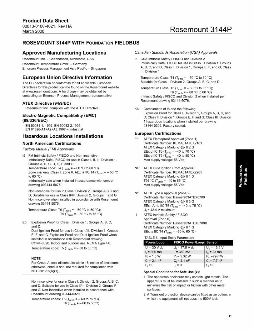
ROSEMOUNT 3144P WITH FOUNDATION FIELDBUS
Approved Manufacturing LocationsRosemount Inc. – Chanhassen, Minnesota, USA
Rosemount Temperature GmbH – Germany
Emerson Process Management Asia Pacific – Singapore
European Union Directive InformationThe EC declaration of conformity for all applicable European
Directives for this product can be found on the Rosemount website
at www.rosemount.com. A hard copy may be obtained by
contacting an Emerson Process Management representative.
ATEX Directive (94/9/EC)Rosemount Inc. complies with the ATEX Directive.
Electro Magnetic Compatibility (EMC)
(89/336/EEC)EN 50081-1: 1992; EN 50082-2:1995; EN 61326-A1+A2+A3:1997 – Industrial
Hazardous Locations Installations
North American Certifications
Factory Mutual (FM) Approvals
I5 FM Intrinsic Safety / FISCO and Non-incendive
Intrinsically Safe / FISCO for use in Class I, II, III, Division 1,
Groups A, B, C, D, E, F, and G;
Temperature code: T4 (Tamb = – 60 °C to 60 °C)
Zone marking: Class I, Zone 0, AEx ia IIC T4 (Tamb = – 50 °C
to 60 °C)
Intrinsically safe when installed in accordance with control
drawing 003144-5075.
Non-incendive for use in Class, Division 2, Groups A,B,C and
D; Suitable for use in Class II/III, Division 2, Groups F and G
Non-incendive when installed in accordance with Rosemount
drawing 03144-5075.
Temperature Class: T6 (Tamb = – 60 °C to 50 °C);
T5 (Tamb = – 60 °C to 75 °C)
E5 Explosion Proof for Class I, Division 1, Groups A, B, C,
and D.
Dust Ignition-Proof for use in Class II/III, Division 1, Groups
E, F, and G. Explosion-Proof and Dust Ignition-Proof when
installed in accordance with Rosemount drawing
03144-0320. Indoor and outdoor use. NEMA Type 4X.
Temperature code: T5 (Tamb = – 50 to 85 °C)
NOTE
For Group A, seal all conduits within 18 inches of enclosure;
otherwise, conduit seal not required for compliance with
NEC 501-15(A)(1).
Non-incendive for use in Class I, Division 2, Groups A, B, C,
and D. Suitable for use in Class II/III, Division 2, Groups F
and G. Non-incendive when installed in accordance with
Rosemount drawing 03144-0320.
Temperature codes: T5 (Tamb = – 60 to 75 °C),
T6 (Tamb = – 60 to 50°C)
Canadian Standards Association (CSA) Approvals
I6 CSA Intrinsic Safety / FISCO and Division 2
Intrinsically Safe / FISCO for use in Class I, Division 1, Groups
A, B, C, and D; Class II, Division 1, Groups E, F, and G; Class
III, Division 1.
Temperature Class: T4 (Tamb = – 50 °C to 60 °C)
Suitable for Class I, Division 2, Groups A, B, C, and D.
Temperature Class: T5 (Tamb = – 60 °C to 85 °C);
T6 (Tamb = – 60 °C to 60 °C)
Intrinsic Safety / FISCO and Division 2 when installed per
Rosemount drawing 03144-5076.
K6 Combination of I6 and the following:
Explosion Proof for Class I, Division 1, Groups A, B, C, and
D; Class II, Division 1, Groups E, F, and G; Class III, Division
1 hazardous locations when installed per drawing
03144-0302. Factory sealed.
European Certifications
E1 ATEX Flameproof Approval (Zone 1)
Certificate Number: KEMA01ATEX2181
ATEX Category Marking II 2 G
EEx d IIC T6 (Tamb = –40 to 70 °C)
EEx d IIC T5 (Tamb = –40 to 80 °C)
Max supply voltage: 55 Vdc
ND ATEX Dust Ignition Proof Approval
Certificate Number: KEMA01ATEX2205
ATEX Category Marking II 1 D
T95 °C (Tamb = –40 to 85 °C)
Max supply voltage: 55 Vdc
N1 ATEX Type n Approval (Zone 2)
Certificate Number: Baseefa03ATEX0709
ATEX Category Marking II 3 G
EEx nA nL IIC T5 (Tamb = –40 to 75 °C)
Ui = 42.4 V maximum
I1 ATEX Intrinsic Safety / FISCO
Approval (Zone 0)
Certificate Number: Baseefa03ATEX0708X
ATEX Category Marking II 1 G
EEx ia IIC T4 (Tamb = –60 to 60 °C)
TABLE 6. Input Entity Parameters
Special Conditions for Safe Use (x):
1. The apparatus enclosure may contain light metals. The
apparatus must be installed in such a manner as to
minimize the risk of impact or friction with other metal
surfaces.
2. A Transient protection device can be fitted as an option, in
which the equipment will not pass the 500V test.
Power/Loop FISCO Power/Loop Sensor
Ui = 30 V dc Ui = 17.5 V dc Uo = 13.9 V
Ii = 300 mA Ii = 380 mA Io = 23 mA
Pi = 1.3 W Pi = 5.32 W Po =79 mW
Ci = 2.1 nF Ci = 2.1 nF Ci = 7.7 nF
Li = 0 Li = 0 Li = 0
11

Product Data Sheet00813-0100-4021, Rev HA
March 2008Rosemount 3144P
Australian Certifications
Standard Australia Quality Assurance Services (SAA)
E7 Flameproof Approval
Certificate Number: AUS Ex 02.3813X
Ex d IIC T6 (Tamb = –20 to 60 °C)
IP66
Special Conditions for Safe Use (x):
1. Apparatus must be installed in accordance to Rosemount
drawing 03144-0325.
2. If the sensor is intended to be remote mounted, it should
be installed in a suitable Standards Australia certified
Flame-Proof enclosure and installed in accordance with
Rosemount drawing 03144-0325.
3. Standards Australia certified cable glands or conduit
adapters must be used when connecting to external
circuits. Where only one conduit entry is used for
connection to external circuits, the unused entry is to be
closed by means of a blanking plug supplied by
Rosemount or by a suitable Standards Australia certified
blanking plug.
I7 Intrinsic Safety Approval
Certificate Number: IECEx BAS 07.0004X
Ex ia IIC T4 (Tamb = –60 to 60 °C)
N7 Type n Approval (Zone 2)
Certificate Number: IECEx BAS 07.0005X
Ex ia IIC T4 (Tamb = –40 to 75 °C)
42.4 Vdc
IP66
Japanese Certifications
Japanese Industrial Standard (JIS) Flameproof
Certification
E4 Consult factory for availability.
Russian GOST Certification
Intrinsically Safe and Explosion-proof (Flameproof)
PPC BA-13006:
1 Ex d IIC T5, T6
0 Ex ia IIC T5, T6
0 Ex ia IIC T4
Combination CertificationsStainless steel certification tag is provided when optional approval
is specified. Once a device labeled with multiple approval types is
installed, it should not be reinstalled using any other approval
types. Permanently mark the approval label to distinguish it from
unused approval types.
KA Combination of K1 and K6
KB Combination of K5 and K6
K1 Combination of E1, N1, and I1
K7 Combination of E7, N7, and I7
K5 Combination of I5 and E5.
12
Product Data Sheet00813-0100-4021, Rev HA
March 2008 Rosemount 3144P
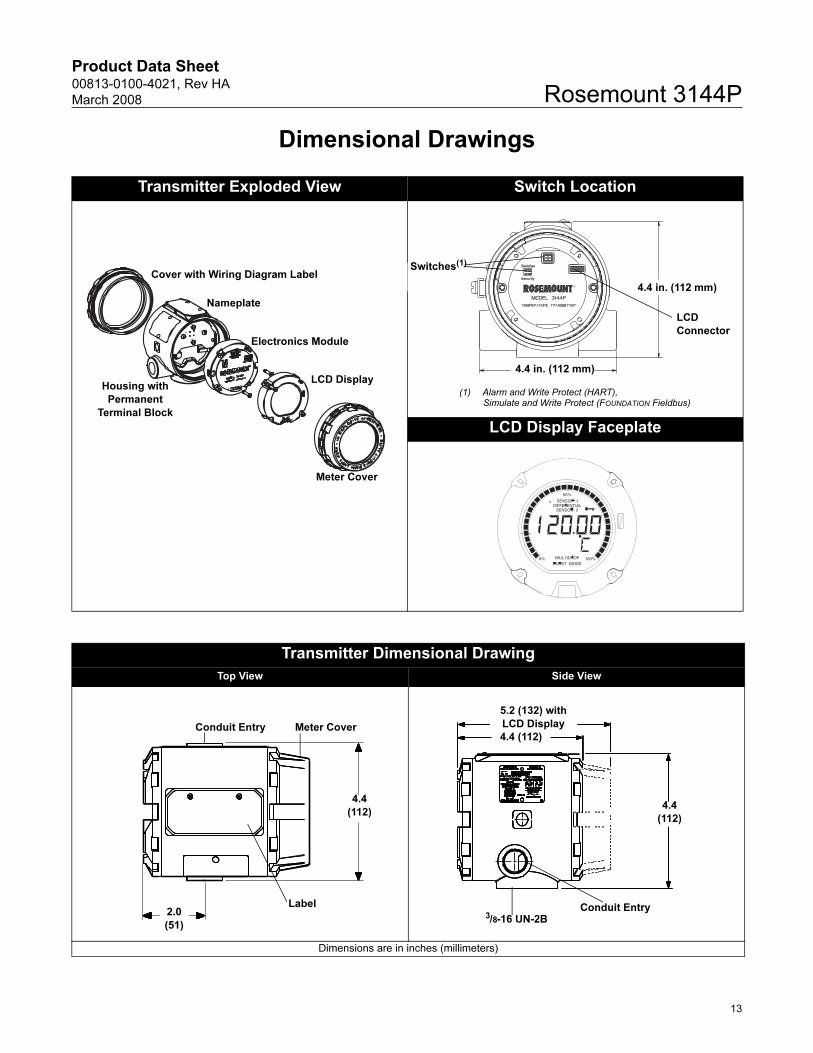
Dimensional Drawings
Transmitter Exploded View Switch Location
LCD Display Faceplate
LCD Display
Electronics Module
Nameplate
Meter Cover
Cover with Wiring Diagram Label
Housing with
Permanent
Terminal Block
Switches(1)
LCD
Connector
4.4 in. (112 mm)
4.4 in. (112 mm)
(1) Alarm and Write Protect (HART), Simulate and Write Protect (FOUNDATION Fieldbus)
Transmitter Dimensional Drawing
Top View Side View
Dimensions are in inches (millimeters)
2.0
(51)
4.4
(112)
Label
Conduit Entry Meter Cover
5.2 (132) with
LCD Display
4.4 (112)
4.4
(112)
Conduit Entry3/8-16 UN-2B
13
Product Data Sheet00813-0100-4021, Rev HA
March 2008Rosemount 3144P
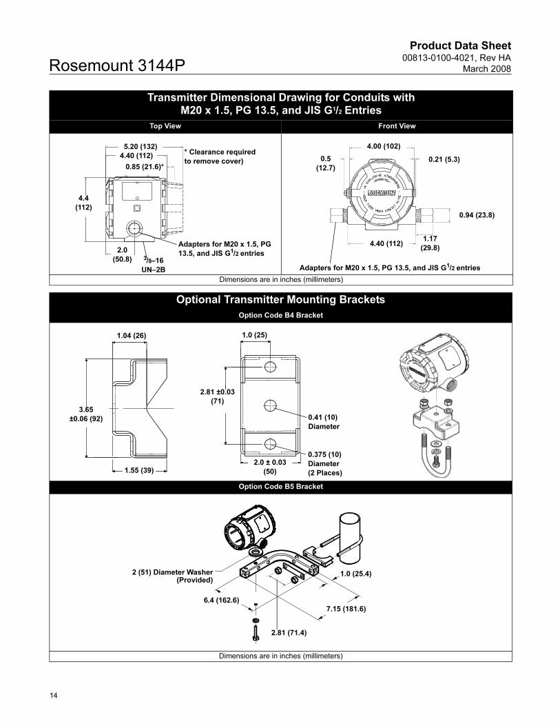
Transmitter Dimensional Drawing for Conduits with M20 x 1.5, PG 13.5, and JIS G1/2 Entries
Top View Front View
Dimensions are in inches (millimeters)
Optional Transmitter Mounting Brackets
Option Code B4 Bracket
Option Code B5 Bracket
Dimensions are in inches (millimeters)
4.4
(112)
2.0
(50.8)
5.20 (132)
4.40 (112)
0.85 (21.6)*
* Clearance required
to remove cover)
Adapters for M20 x 1.5, PG
13.5, and JIS G1/2 entries3/8–16
UN–2B
4.40 (112)1.17
(29.8)
0.94 (23.8)
0.21 (5.3)
4.00 (102)
0.5
(12.7)
Adapters for M20 x 1.5, PG 13.5, and JIS G1/2 entries
1.04 (26)
1.55 (39)
3.65
±0.06 (92)
1.0 (25)
2.81 ±0.03
(71)
0.41 (10)
Diameter
0.375 (10)
Diameter
(2 Places)
2.0 ± 0.03
(50)
1.0 (25.4)
7.15 (181.6)
2 (51) Diameter Washer(Provided)
6.4 (162.6)
2.81 (71.4)
14
Product Data Sheet00813-0100-4021, Rev HA
March 2008 Rosemount 3144P
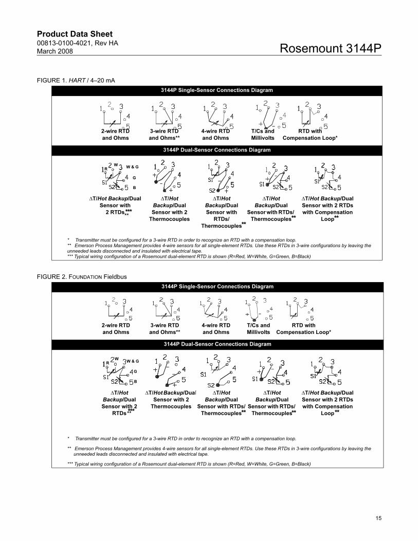
FIGURE 1. HART / 4–20 mA
3144P Single-Sensor Connections Diagram
3144P Dual-Sensor Connections Diagram
* Transmitter must be configured for a 3-wire RTD in order to recognize an RTD with a compensation loop.** Emerson Process Management provides 4-wire sensors for all single-element RTDs. Use these RTDs in 3-wire configurations by leaving the unneeded leads disconnected and insulated with electrical tape.*** Typical wiring configuration of a Rosemount dual-element RTD is shown (R=Red, W=White, G=Green, B=Black)
4-wire RTD
and Ohms
T/Cs and
Millivolts
RTD with
Compensation Loop*
2-wire RTD
and Ohms
3-wire RTD
and Ohms**
ΔT/Hot Backup/Dual
Sensor with
2 RTDs
ΔT/Hot
Backup/Dual
Sensor with 2
Thermocouples
ΔT/Hot
Backup/Dual
Sensor with RTDs/
Thermocouples
ΔT/Hot
Backup/Dual
Sensor with
RTDs/
Thermocouples
ΔT/Hot Backup/Dual
Sensor with 2 RTDs
with Compensation
Loop
***
R
WW & G
G
B
** ** ****
FIGURE 2. FOUNDATION Fieldbus
3144P Single-Sensor Connections Diagram
3144P Dual-Sensor Connections Diagram
* Transmitter must be configured for a 3-wire RTD in order to recognize an RTD with a compensation loop.
** Emerson Process Management provides 4-wire sensors for all single-element RTDs. Use these RTDs in 3-wire configurations by leaving the unneeded leads disconnected and insulated with electrical tape.
*** Typical wiring configuration of a Rosemount dual-element RTD is shown (R=Red, W=White, G=Green, B=Black)
4-wire RTD
and Ohms
T/Cs and
Millivolts
RTD with
Compensation Loop*
2-wire RTD
and Ohms
3-wire RTD
and Ohms**
ΔT/Hot
Backup/Dual
Sensor with 2
RTDs
ΔT/Hot Backup/Dual
Sensor with 2
Thermocouples
ΔT/Hot
Backup/Dual
Sensor with RTDs/
Thermocouples
ΔT/Hot
Backup/Dual
Sensor with RTDs/
Thermocouples
ΔT/Hot Backup/Dual
Sensor with 2 RTDs
with Compensation
Loop***
R
WW & G
G
B
** ** ****
15
Product Data Sheet00813-0100-4021, Rev HA
March 2008Rosemount 3144P
16
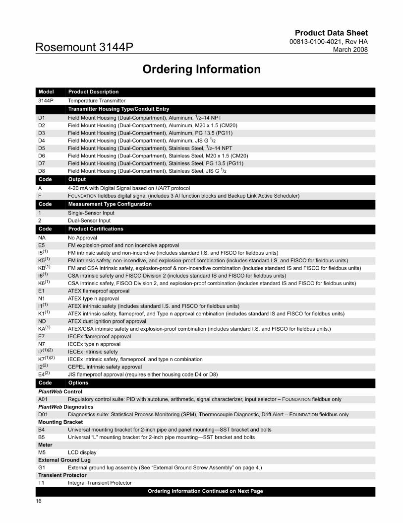
Ordering Information
Model Product Description
3144P Temperature Transmitter
Code Transmitter Housing Type/Conduit Entry
D1 Field Mount Housing (Dual-Compartment), Aluminum, 1/2–14 NPT
D2 Field Mount Housing (Dual-Compartment), Aluminum, M20 x 1.5 (CM20)
D3 Field Mount Housing (Dual-Compartment), Aluminum, PG 13.5 (PG11)
D4 Field Mount Housing (Dual-Compartment), Aluminum, JIS G 1/2
D5 Field Mount Housing (Dual-Compartment), Stainless Steel, 1/2–14 NPT
D6 Field Mount Housing (Dual-Compartment), Stainless Steel, M20 x 1.5 (CM20)
D7 Field Mount Housing (Dual-Compartment), Stainless Steel, PG 13.5 (PG11)
D8 Field Mount Housing (Dual-Compartment), Stainless Steel, JIS G 1/2
Code Output
A 4-20 mA with Digital Signal based on HART protocol
F FOUNDATION fieldbus digital signal (includes 3 AI function blocks and Backup Link Active Scheduler)
Code Measurement Type Configuration
1 Single-Sensor Input
2 Dual-Sensor Input
Code Product Certifications
NA No Approval
E5 FM explosion-proof and non incendive approval
I5(1) FM intrinsic safety and non-incendive (includes standard I.S. and FISCO for fieldbus units)
K5(1) FM intrinsic safety, non-incendive, and explosion-proof combination (includes standard I.S. and FISCO for fieldbus units)
KB(1) FM and CSA intrinsic safety, explosion-proof & non-incendive combination (includes standard IS and FISCO for fieldbus units)
I6(1) CSA intrinsic safety and FISCO Division 2 (includes standard IS and FISCO for fieldbus units)
K6(1) CSA intrinsic safety, FISCO Division 2, and explosion-proof combination (includes standard IS and FISCO for fieldbus units)
E1 ATEX flameproof approval
N1 ATEX type n approval
I1(1) ATEX intrinsic safety (includes standard I.S. and FISCO for fieldbus units)
K1(1) ATEX intrinsic safety, flameproof, and Type n approval combination (includes standard IS and FISCO for fieldbus units)
ND ATEX dust ignition proof approval
KA(1) ATEX/CSA intrinsic safety and explosion-proof combination (includes standard I.S. and FISCO for fieldbus units.)
E7 IECEx flameproof approval
N7 IECEx type n approval
I7(1)(2) IECEx intrinsic safety
K7(1)(2) IECEx intrinsic safety, flameproof, and type n combination
I2(2) CEPEL intrinsic safety approval
E4(2) JIS flameproof approval (requires either housing code D4 or D8)
Code Options
PlantWeb Control
A01 Regulatory control suite: PID with autotune, arithmetic, signal characterizer, input selector – FOUNDATION fieldbus only
PlantWeb Diagnostics
D01 Diagnostics suite: Statistical Process Monitoring (SPM), Thermocouple Diagnostic, Drift Alert – FOUNDATION fieldbus only
Mounting Bracket
B4 Universal mounting bracket for 2-inch pipe and panel mounting—SST bracket and bolts
B5 Universal “L” mounting bracket for 2-inch pipe mounting—SST bracket and bolts
Meter
M5 LCD display
External Ground Lug
G1 External ground lug assembly (See “External Ground Screw Assembly” on page 4.)
Transient Protector
T1 Integral Transient Protector
Ordering Information Continued on Next Page
Product Data Sheet00813-0100-4021, Rev HA
March 2008 Rosemount 3144P
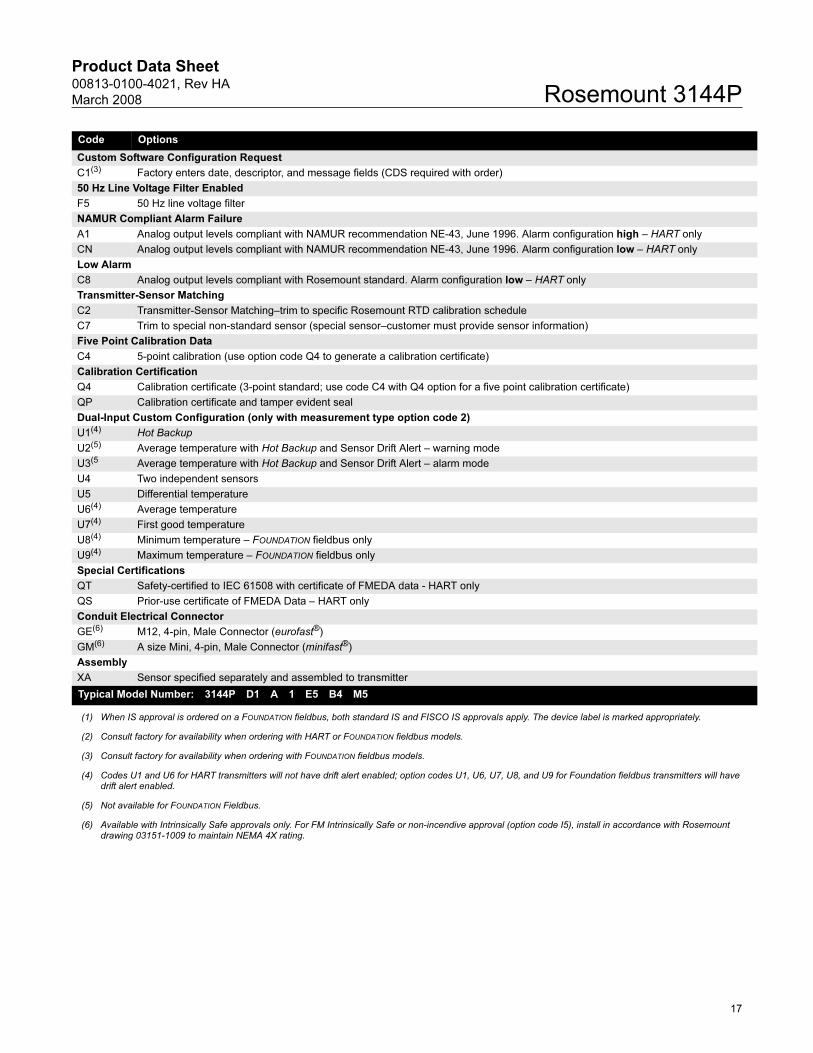
Code Options
Custom Software Configuration Request
C1(3) Factory enters date, descriptor, and message fields (CDS required with order)
50 Hz Line Voltage Filter Enabled
F5 50 Hz line voltage filter
NAMUR Compliant Alarm Failure
A1 Analog output levels compliant with NAMUR recommendation NE-43, June 1996. Alarm configuration high – HART only
CN Analog output levels compliant with NAMUR recommendation NE-43, June 1996. Alarm configuration low – HART only
Low Alarm
C8 Analog output levels compliant with Rosemount standard. Alarm configuration low – HART only
Transmitter-Sensor Matching
C2 Transmitter-Sensor Matching–trim to specific Rosemount RTD calibration schedule
C7 Trim to special non-standard sensor (special sensor–customer must provide sensor information)
Five Point Calibration Data
C4 5-point calibration (use option code Q4 to generate a calibration certificate)
Calibration Certification
Q4 Calibration certificate (3-point standard; use code C4 with Q4 option for a five point calibration certificate)
QP Calibration certificate and tamper evident seal
Dual-Input Custom Configuration (only with measurement type option code 2)
U1(4) Hot Backup
U2(5) Average temperature with Hot Backup and Sensor Drift Alert – warning mode
U3(5 Average temperature with Hot Backup and Sensor Drift Alert – alarm mode
U4 Two independent sensors
U5 Differential temperature
U6(4) Average temperature
U7(4) First good temperature
U8(4) Minimum temperature – FOUNDATION fieldbus only
U9(4) Maximum temperature – FOUNDATION fieldbus only
Special Certifications
QT Safety-certified to IEC 61508 with certificate of FMEDA data - HART only
QS Prior-use certificate of FMEDA Data – HART only
Conduit Electrical Connector
GE(6) M12, 4-pin, Male Connector (eurofast®)
GM(6) A size Mini, 4-pin, Male Connector (minifast®)
Assembly
XA Sensor specified separately and assembled to transmitter
Typical Model Number: 3144P D1 A 1 E5 B4 M5
(1) When IS approval is ordered on a FOUNDATION fieldbus, both standard IS and FISCO IS approvals apply. The device label is marked appropriately.
(2) Consult factory for availability when ordering with HART or FOUNDATION fieldbus models.
(3) Consult factory for availability when ordering with FOUNDATION fieldbus models.
(4) Codes U1 and U6 for HART transmitters will not have drift alert enabled; option codes U1, U6, U7, U8, and U9 for Foundation fieldbus transmitters will have drift alert enabled.
(5) Not available for FOUNDATION Fieldbus.
(6) Available with Intrinsically Safe approvals only. For FM Intrinsically Safe or non-incendive approval (option code I5), install in accordance with Rosemount drawing 03151-1009 to maintain NEMA 4X rating.
17

Product Data Sheet00813-0100-4021, Rev HA
March 2008Rosemount 3144P
Standard Configuration
Both standard and custom configuration settings may be changed. Unless specified, the transmitter will be shipped as follows:
Custom Configuration
The 3144P transmitter can be ordered with custom configuration. The table below lists the requirements necessary to specify a custom
configuration.
(1) CDS required
Standard Configuration
4 mA value / Lower Range (HART / 4–20 mA) Measurement Point LO (FOUNDATION Fieldbus) 0 °C
20 mA value / Upper Range (HART / 4–20 mA) Measurement Point HI (FOUNDATION Fieldbus) 100 °C
Damping 5 seconds
Output Linear with temperature / FOUNDATION fieldbus
Failure Mode (HART / 4–20 mA) High
Line Voltage Filter 60 Hz
Software Tag See “Tagging”
Optional Integral Meter Units and mA / Sensor 1 units
Single Sensor option
Sensor Type 4-wire Pt 100 α = 0.00385 RTD
Primary Variable (HART / 4–20 mA) AI 1400 (FOUNDATION Fieldbus) Sensor 1
Secondary Variable AI 1600 (FOUNDATION Fieldbus) Terminal Temperature
Tertiary Variable Not Available
Quaternary Variable Not Available
Dual-Sensor option
Sensor Type Two 3-wire Pt 100 α = 0.00385 RTD
Primary Variable (HART / 4–20 mA) AI 1400 (FOUNDATION Fieldbus) Sensor 1
Secondary Variable AI 1500 (FOUNDATION Fieldbus) Sensor 2
Tertiary Variable AI 1600 (FOUNDATION Fieldbus) Terminal Temperature
Quaternary Variable Not Used
Option Code Requirements/Specification
C1:
Factory Data(1)Date: day/month/year
Descriptor: 16 alphanumeric character
Message: 32 alphanumeric character
Custom Alarm Levels can be specified for configuration at the factory.
C2:
Transmitter Sensor Matching
The transmitters are designed to accept Callendar-van Dusen constants from a calibrated RTD
schedule and generate a custom curve to match any specific sensor curve. Specify a Series 68, 65, or
78 RTD sensor on the order with a special characterization curve (V or X8Q4 option). These constants
will be programmed into the transmitter with this option.
C4:
Five Point Calibration
Will include five-point calibration at 0, 25, 50, 75, and 100% analog and digital output points.
Use with option code Q4 to obtain a Calibration Certificate.
C7:
Special Sensor
Used for non-standard sensor, adding a special sensor or expanding input.
Customer must supply the non-standard sensor information.Additional special curve will be added to
sensor curve input choices.
A1: NAMUR-
Compliant, high alarm
Analog output levels compliant with NAMUR. Alarm is set to fail high.
CN: NAMUR-
Compliant, low alarm
Analog output levels compliant with NAMUR. Alarm is set to fail low.
C8: Low Alarm Analog output levels compliant with Rosemount standard. Alarm is set to fail low
F5: 50 Hz Line Filter Calibrated to 50 Hz line voltage filter.
18

Product Data Sheet00813-0100-4021, Rev HA
March 2008 Rosemount 3144P
To custom configure the 3144P with the dual-sensor option transmitter for one of the applications described below, indicate the appropriate
option code in the model number. If a sensor type is not specified, the transmitter will be configured for two 3-wire Pt 100 (α = 0.00385) RTDs if
any of the following option codes are selected.
Option Code U1: Hot Backup
Primary Usage Primary usage sets the transmitter to automatically use sensor 2 as the primary input if sensor 1 fails.
Switching from sensor 1 to sensor 2 is accomplished without any effect on the analog signal.
Primary Variable 1st good
Secondary Variable Sensor 1
Tertiary Variable Sensor 2
Quaternary Variable Terminal Temperature
Option Code U2: Average Temperature with Hot Backup and Sensor Drift Alert – Warning Mode
Primary Usage Critical applications, such as safety interlocks and control loops. Outputs the average of two
measurements and alerts if temperature difference exceeds the set maximum differential (Sensor Drift
Alert – warning mode). If a sensor fails, an alert will be sent digitally. The primary variable will be reported
as the remaining working sensor value.
Primary Variable Sensor Average
Secondary Variable Sensor 1
Tertiary Variable Sensor 2
Quaternary Variable Terminal Temperature
Option Code U3: Average temperature with Hot Backup and Sensor Drift Alert – Alarm Mode
Primary Usage Critical applications, such as safety interlocks and control loops. Outputs the average of two
measurements and alarms if temperature difference exceeds the set maximum differential (Sensor Drift
Alert – alarm mode). If a sensor fails, an alert will be sent digitally. The primary variable will be reported as
the remaining working sensor value.
Primary Variable Sensor Average
Secondary Variable Sensor 1
Tertiary Variable Sensor 2
Quaternary Variable Terminal Temperature
Option Code U4: Two Independent Sensors
Primary Usage Used in non-critical applications where the digital output is used to measure two separate process
temperatures.
Primary Variable Sensor 1
Secondary Variable Sensor 2
Tertiary Variable Terminal Temperature
Quaternary Variable Not Used
Option Code U5 Differential Temperature
Primary Usage The differential temperature of two process temperatures is configured as the primary variable.
Primary Variable Differential Temperature
Secondary Variable Sensor 1
Tertiary Variable Sensor 2
Quaternary Variable Terminal Temperature
Option Code U6: Average Temperature
Primary Usage When average measurement of two different process temperatures is required.If a sensor fails, an alert will
be sent and the primary variable will use the measurement of the working sensor.
Primary Variable Sensor Average
Secondary Variable Sensor 1
Tertiary Variable Sensor 2
Quaternary Variable Terminal Temperature
19
Product Data Sheet00813-0100-4021, Rev HA
March 2008Rosemount 3144P
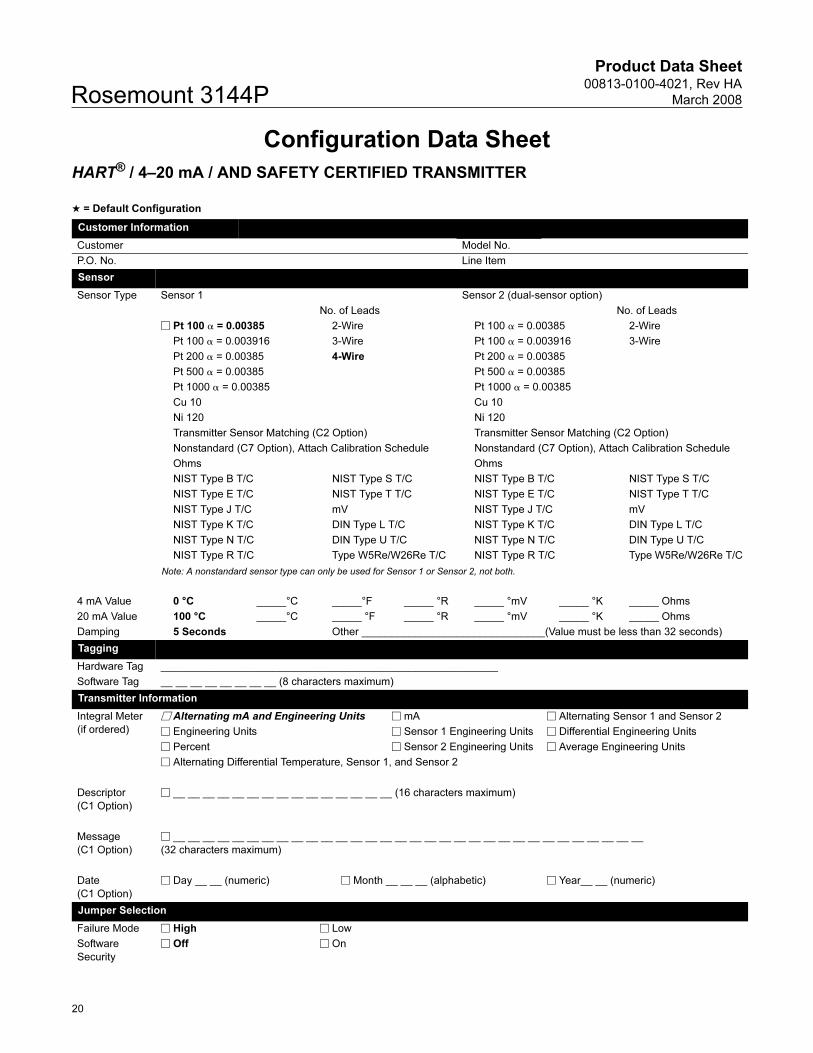
Configuration Data Sheet
HART® / 4–20 mA / AND SAFETY CERTIFIED TRANSMITTER
★ = Default Configuration
Customer Information
Customer Model No.
P.O. No. Line Item
Sensor
Sensor Type Sensor 1 Sensor 2 (dual-sensor option)
No. of Leads No. of Leads
� Pt 100 � = 0.00385 2-Wire Pt 100 � = 0.00385 2-Wire
Pt 100 � = 0.003916 3-Wire Pt 100 � = 0.003916 3-Wire
Pt 200 � = 0.00385 4-Wire Pt 200 � = 0.00385
Pt 500 � = 0.00385 Pt 500 � = 0.00385
Pt 1000 � = 0.00385 Pt 1000 � = 0.00385
Cu 10 Cu 10
Ni 120 Ni 120
Transmitter Sensor Matching (C2 Option) Transmitter Sensor Matching (C2 Option)
Nonstandard (C7 Option), Attach Calibration Schedule Nonstandard (C7 Option), Attach Calibration Schedule
Ohms Ohms
NIST Type B T/C NIST Type S T/C NIST Type B T/C NIST Type S T/C
NIST Type E T/C NIST Type T T/C NIST Type E T/C NIST Type T T/C
NIST Type J T/C mV NIST Type J T/C mV
NIST Type K T/C DIN Type L T/C NIST Type K T/C DIN Type L T/C
NIST Type N T/C DIN Type U T/C NIST Type N T/C DIN Type U T/C
NIST Type R T/C Type W5Re/W26Re T/C NIST Type R T/C Type W5Re/W26Re T/C
Note: A nonstandard sensor type can only be used for Sensor 1 or Sensor 2, not both.
4 mA Value 0 °C _____°C _____°F _____ °R _____ °mV _____ °K _____ Ohms
20 mA Value 100 °C _____°C _____ °F _____ °R _____ °mV _____ °K _____ Ohms
Damping 5 Seconds Other _______________________________(Value must be less than 32 seconds)
Tagging
Hardware Tag _________________________________________________________
Software Tag __ __ __ __ __ __ __ __ (8 characters maximum)
Transmitter Information
Integral Meter
(if ordered)
� Alternating mA and Engineering Units � mA � Alternating Sensor 1 and Sensor 2
� Engineering Units � Sensor 1 Engineering Units � Differential Engineering Units
� Percent � Sensor 2 Engineering Units � Average Engineering Units
� Alternating Differential Temperature, Sensor 1, and Sensor 2
Descriptor
(C1 Option)
� __ __ __ __ __ __ __ __ __ __ __ __ __ __ __ (16 characters maximum)
Message
(C1 Option)
� __ __ __ __ __ __ __ __ __ __ __ __ __ __ __ __ __ __ __ __ __ __ __ __ __ __ __ __ __ __ __ __
(32 characters maximum)
Date
(C1 Option)
� Day __ __ (numeric) � Month __ __ __ (alphabetic) � Year__ __ (numeric)
Jumper Selection
Failure Mode � High � Low
Software
Security
� Off � On
20
Product Data Sheet00813-0100-4021, Rev HA
March 2008 Rosemount 3144P
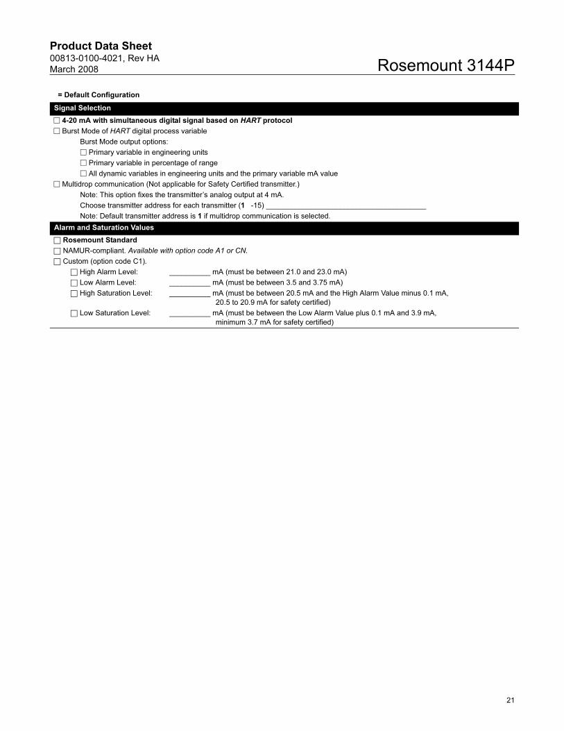
Signal Selection
� 4-20 mA with simultaneous digital signal based on HART protocol
� Burst Mode of HART digital process variable
Burst Mode output options:
� Primary variable in engineering units
� Primary variable in percentage of range
� All dynamic variables in engineering units and the primary variable mA value
� Multidrop communication (Not applicable for Safety Certified transmitter.)
Note: This option fixes the transmitter’s analog output at 4 mA.
Choose transmitter address for each transmitter (1 -15) _______________________________________
Note: Default transmitter address is 1 if multidrop communication is selected.
Alarm and Saturation Values
□ Rosemount Standard
□ NAMUR-compliant. Available with option code A1 or CN.
□ Custom (option code C1).
□ High Alarm Level: __________ mA (must be between 21.0 and 23.0 mA)
□ Low Alarm Level: __________ mA (must be between 3.5 and 3.75 mA)
□ High Saturation Level: __________ mA (must be between 20.5 mA and the High Alarm Value minus 0.1 mA,
20.5 to 20.9 mA for safety certified)
□ Low Saturation Level: __________ mA (must be between the Low Alarm Value plus 0.1 mA and 3.9 mA,
minimum 3.7 mA for safety certified)
= Default Configuration
21
Product Data Sheet00813-0100-4021, Rev HA
March 2008Rosemount 3144P
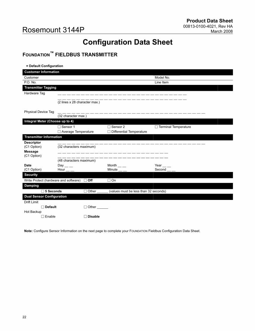
Configuration Data Sheet
FOUNDATION™ FIELDBUS TRANSMITTER
= Default Configuration
Customer Information
Customer Model No.
P.O. No. Line Item
Transmitter Tagging
Hardware Tag __ __ __ __ __ __ __ __ __ __ __ __ __ __ __ __ __ __ __ __ __ __ __ __ __ __ __ __
__ __ __ __ __ __ __ __ __ __ __ __ __ __ __ __ __ __ __ __ __ __ __ __ __ __ __ __
(2 lines x 28 character max.)
Physical Device Tag __ __ __ __ __ __ __ __ __ __ __ __ __ __ __ __ __ __ __ __ __ __ __ __ __ __ __ __ __ __ __ __
(32 character max.)
Integral Meter (Choose up to 4)
� Sensor 1 � Sensor 2 � Terminal Temperature
� Average Temperature � Differential Temperature
Transmitter Information
Descriptor
(C1 Option)
__ __ __ __ __ __ __ __ __ __ __ __ __ __ __ __ __ __ __ __ __ __ __ __ __ __ __ __ __ __ __ __
(32 characters maximum)
Message
(C1 Option)
__ __ __ __ __ __ __ __ __ __ __ __ __ __ __ __ __ __ __ __ __ __ __ __
__ __ __ __ __ __ __ __ __ __ __ __ __ __ __ __ __ __ __ __ __ __ __ __
(48 characters maximum)
Date
(C1 Option)
Day __ __
Hour __ __
Month __ __
Minute __ __
Year __ __
Second __ __
Security
Write Protect (hardware and software) � Off � On
Damping
� 5 Seconds � Other ______ (values must be less than 32 seconds)
Dual Sensor Configuration
Drift Limit
� Default � Other ______
Hot Backup
� Enable � Disable
Note: Configure Sensor Information on the next page to complete your FOUNDATION Fieldbus Configuration Data Sheet.
22
Product Data Sheet00813-0100-4021, Rev HA
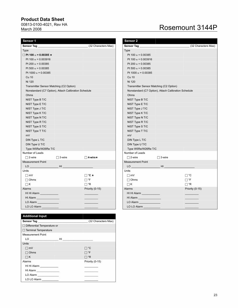
March 2008 Rosemount 3144P
Sensor 1 Sensor 2
Sensor Tag _________________________________ (32 Characters Max) Sensor Tag _________________________________ (32 Characters Max)
Type Type
� Pt 100 � = 0.00385 ★ Pt 100 � = 0.00385
Pt 100 � = 0.003916 Pt 100 � = 0.003916
Pt 200 � = 0.00385 Pt 200 � = 0.00385
Pt 500 � = 0.00385 Pt 500 � = 0.00385
Pt 1000 � = 0.00385 Pt 1000 � = 0.00385
Cu 10 Cu 10
Ni 120 Ni 120
Transmitter Sensor Matching (C2 Option) Transmitter Sensor Matching (C2 Option)
Nonstandard (C7 Option), Attach Calibration Schedule Nonstandard (C7 Option), Attach Calibration Schedule
Ohms Ohms
NIST Type B T/C NIST Type B T/C
NIST Type E T/C NIST Type E T/C
NIST Type J T/C NIST Type J T/C
NIST Type K T/C NIST Type K T/C
NIST Type N T/C NIST Type N T/C
NIST Type R T/C NIST Type R T/C
NIST Type S T/C NIST Type S T/C
NIST Type T T/C NIST Type T T/C
mV mV
DIN Type L T/C DIN Type L T/C
DIN Type U T/C DIN Type U T/C
Type W5Re/W26Re T/C Type W5Re/W26Re T/C
Number of Leads Number of Leads
□ 2-wire □ 3-wire □ 4-wire★ □ 2-wire □ 3-wire
Measurement Point Measurement Point
LO ___________________ HI ____________________ LO ___________________ HI ____________________
Units Units
□ mV □ °C ★ □ mV □ °C
□ Ohms □ °F □ Ohms □ °F
□ K □ °R □ K □ °R
Alarms Priority (0-15) Alarms Priority (0-15)
HI HI Alarm ____________ _________ HI HI Alarm ____________ _________
HI Alarm _______________ _________ HI Alarm _______________ _________
LO Alarm ______________ _________ LO Alarm ______________ _________
LO LO Alarm ___________ _________ LO LO Alarm ___________ _________
Additional Input
Sensor Tag _________________________________ (32 Characters Max)
� Differential Temperature or
� Terminal Temperature
Measurement Point
LO ___________________ HI ____________________
Units
□ mV □ °C
□ Ohms □ °F
□ K □ °R
Alarms Priority (0-15)
HI HI Alarm ____________ _________
HI Alarm _______________ _________
LO Alarm ______________ _________
LO LO Alarm ___________ _________
23

Product Data Sheet00813-0100-4021, Rev HA
March 2008Rosemount 3144P
24

Product Data Sheet00813-0100-4021, Rev HA
March 2008 Rosemount 3144P
25

Product Data Sheet00813-0100-4021, Rev HA
March 2008Rosemount 3144P
26

Product Data Sheet00813-0100-4021, Rev HA
March 2008
27
Rosemount 3144P
Product Data Sheet00813-0100-4021, Rev HA
March 2008 Rosemount 3144P
Emerson Process Management
© 2008 Rosemount, Inc.
The Emerson logo is a trademark and service mark of Emerson Electric Co.Rosemount, the Rosemount logotype, and Hot Backup are registered trademarks of Rosemount Inc.PlantWeb and the PlantWeb logotype is a registered trademark of Emerson Process Management.HART is a registered trademark of the HART Communication Foundation.Eurofast and Minifast are registered trademarks of Turck Inc.FOUNDATION is a trademark of the Fieldbus Foundation.All other marks are the property of their respective owners.
Standard Terms and Conditions of Sale can be found at www.rosemount.com\terms_of_sale
¢00813-0100-4021W¤
Emerson Process Management Asia Pacific Private Limited1 Pandan CrescentSingapore 128461T (65) 6777 8211F (65) 6777 [email protected]
Rosemount Inc.8200 Market BoulevardChanhassen, MN 55317 USAT (U.S.) 1-800-999-9307T (International) (952) 906-8888F (952) 949-7001
www.rosemount.com
Emerson Process ManagementHeath PlaceBognor RegisWest Sussex PO22 9SHEnglandTel 44 (1243) 863 121Fax 44 (1243) 867 5541