Embed Size (px)
Citation preview

MIO-R46RXR20170 Rev D
G&B Specialties Inc. 535 West 3rd
Street, Berwick, PA, USA Tel: (570) 752-5901 Fax: (570) 752-6397
- 1 -
INSTALLATION, OPERATIONS, SERVICE AND PARTS
ROTARY REAR R-460 RAILGEAR
HD ROTARY REAR R-460 RAILGEAR
2008 FORD F-450/550 4X2/4X4

MIO-R46RXR20170 Rev D
G&B Specialties Inc. 535 West 3rd
Street, Berwick, PA, USA Tel: (570) 752-5901 Fax: (570) 752-6397
- 2 -
SAFETY PRECAUTIONS
If any installation problems are encountered, please call G&B Specialties for
technical assistance before continuing with the installation process.
Failure to heed to any of the following warnings could result in severe
bodily injury and/or equipment damage.
Read and understand this manual completely before attempting
installation of the equipment.
Installation instructions provided below only address the Rafna
Industries railgear equipment. Applicable railway company
procedures and policies must be adhered to.
Before performing any work under the vehicle or railgear, ensure the
engine is turned off and the parking brake is set.
Do not start the vehicle with the power steering hoses disconnected.
Reconnect all hoses, and secure the power steering cooler if the vehicle
is started.
Ensure all removed components are given to the vehicle owner after
the installation of the railgear. These components must be re-installed
if the railgear is removed from the vehicle.
Always disconnect the vehicle’s battery when welding on the vehicle
or railgear in order to protect the vehicle’s electrical system.
!

MIO-R46RXR20170 Rev D
G&B Specialties Inc. 535 West 3rd
Street, Berwick, PA, USA Tel: (570) 752-5901 Fax: (570) 752-6397
- 3 -
TABLE OF CONTENTS
SECTION DESCRIPTION Pg.
1.0 Installation
Rear Railgear Kit Components ............................................... 4-5
HD Rear Railgear Kit Components ......................................... 5-6
Rear Railgear Installation ........................................................ 6
Railgear Lock System Installation/Adjustment ....................... 11
2.0 Operations
Placing vehicle on rail ................................................................. 15-16
Removing Vehicle from rail ..................................................... 15-16
3.0 Service
Recommended Service Schedule ............................................... 17
Standard fastener torque values ............................................... 18
Railgear Lubrication ................................................................. 18
Railgear over center adjustment ............................................... 19
Railwheel Bearing Adjustment .................................................. 20
Rail sweep Adjustment .............................................................. 20
Rail Wheel Load Adjustment ..................................................... 21
Railgear alignment ....................................................................... 24
Alignment inspection sheet ..................................................... 25
Rear Spring Replacement ............................................................ 26
4.0 Parts
Railgear Assembly, Complete (manual lock, no brakes) 28
HD Railgear Assembly, Complete (manual lock, no brakes) 29
Railgear Assembly, Complete (hydraulic lock, no brakes) 30
HD Railgear Assembly, Complete (hydraulic lock, no brakes) 31
Railgear Assembly, Complete (manual lock, brakes) 32
HD Railgear Assembly, Complete (manual lock, brakes) 33
Railgear Assembly, Complete (hydraulic lock, brakes) 34
HD Railgear Assembly, Complete (hydraulic lock, brakes) 35
Railgear Upper Assembly 36
HD Railgear Upper Assembly 37
Hydraulic Cylinder 38
Lockup Assembly, Manual 39
Lockup Assembly, Hydraulic 40
Rail Wheel Assembly, complete 41
Rail Wheel Spindle Assembly 42
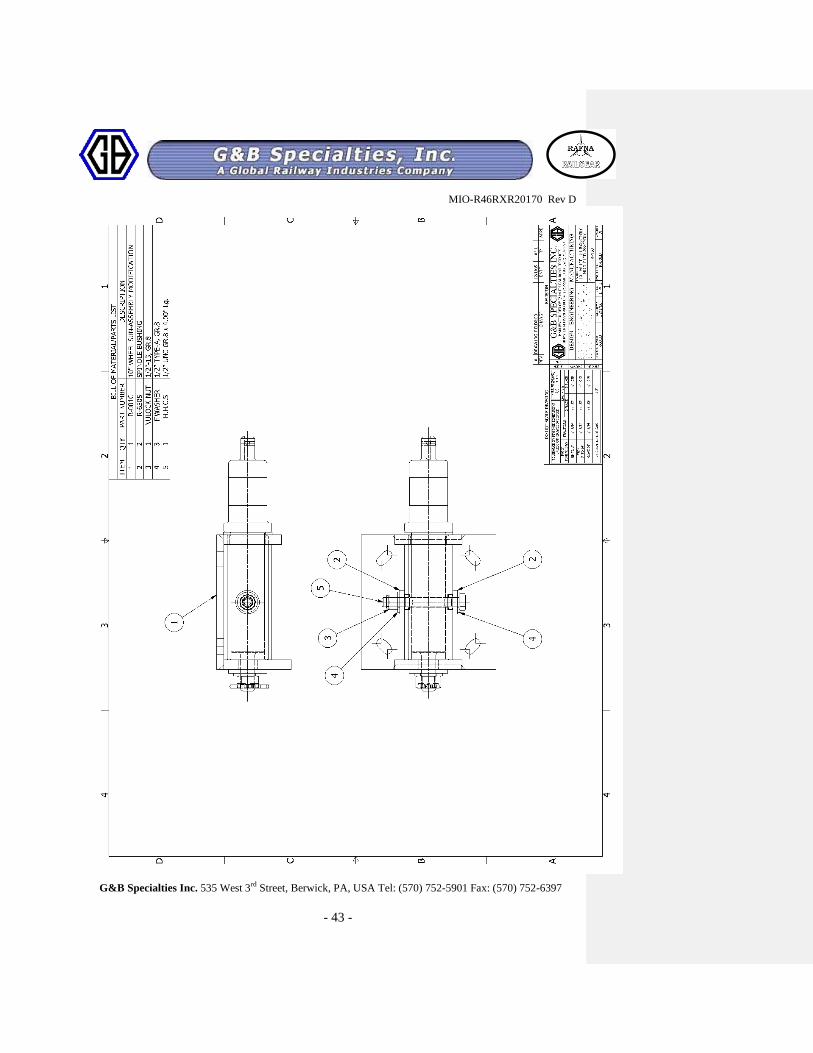
Rail Sweep, Drivers Side 43
Rail Sweep, Passengers Side 44
MIO-R46RXR20170 Rev D
G&B Specialties Inc. 535 West 3rd
Street, Berwick, PA, USA Tel: (570) 752-5901 Fax: (570) 752-6397
- 4 -
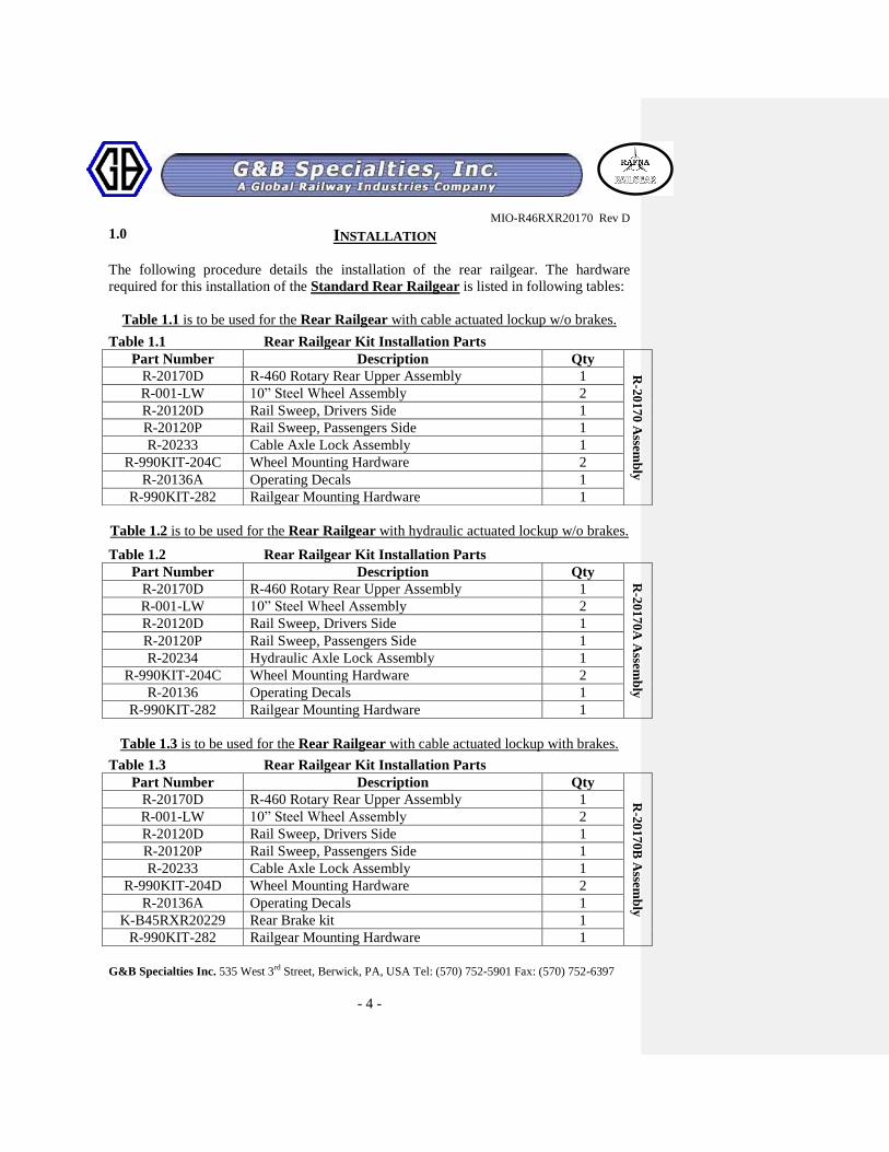
1.0 INSTALLATION
The following procedure details the installation of the rear railgear. The hardware
required for this installation of the Standard Rear Railgear is listed in following tables:
Table 1.1 is to be used for the Rear Railgear with cable actuated lockup w/o brakes.
Table 1.2 is to be used for the Rear Railgear with hydraulic actuated lockup w/o brakes.
Table 1.3 is to be used for the Rear Railgear with cable actuated lockup with brakes.
Table 1.1 Rear Railgear Kit Installation Parts
Part Number Description Qty
R-2
01
70
Assem
bly
R-20170D R-460 Rotary Rear Upper Assembly 1
R-001-LW 10” Steel Wheel Assembly 2
R-20120D Rail Sweep, Drivers Side 1
R-20120P Rail Sweep, Passengers Side 1
R-20233 Cable Axle Lock Assembly 1
R-990KIT-204C Wheel Mounting Hardware 2
R-20136A Operating Decals 1
R-990KIT-282 Railgear Mounting Hardware 1
Table 1.2 Rear Railgear Kit Installation Parts
Part Number Description Qty
R-2
01
70
A A
ssemb
ly
R-20170D R-460 Rotary Rear Upper Assembly 1
R-001-LW 10” Steel Wheel Assembly 2
R-20120D Rail Sweep, Drivers Side 1
R-20120P Rail Sweep, Passengers Side 1
R-20234 Hydraulic Axle Lock Assembly 1
R-990KIT-204C Wheel Mounting Hardware 2
R-20136 Operating Decals 1
R-990KIT-282 Railgear Mounting Hardware 1
Table 1.3 Rear Railgear Kit Installation Parts
Part Number Description Qty
R-2
0170B
Assem
bly
R-20170D R-460 Rotary Rear Upper Assembly 1
R-001-LW 10” Steel Wheel Assembly 2
R-20120D Rail Sweep, Drivers Side 1
R-20120P Rail Sweep, Passengers Side 1
R-20233 Cable Axle Lock Assembly 1
R-990KIT-204D Wheel Mounting Hardware 2
R-20136A Operating Decals 1
K-B45RXR20229 Rear Brake kit 1
R-990KIT-282 Railgear Mounting Hardware 1

MIO-R46RXR20170 Rev D
G&B Specialties Inc. 535 West 3rd
Street, Berwick, PA, USA Tel: (570) 752-5901 Fax: (570) 752-6397
- 5 -
Table 1.4 is to be used for the Rear Railgear with hydraulic actuated lockup with brakes.
The hardware required for this installation of the HD Rear Railgear is listed in following tables:
Table 2.1 is to be used for the HD Rear Railgear with cable actuated lockup w/o brakes.
Table 2.2 is to be used for the HD Rear Railgear with hydraulic actuated lockup w/o brakes.
Table 1.4 Rear Railgear Kit Installation Parts
Part Number Description Qty
R-2
0170C
Assem
bly
R-20170D R-460 Rotary Rear Upper Assembly 1
R-001-LW 10” Steel Wheel Assembly 2
R-20120D Rail Sweep, Drivers Side 1
R-20120P Rail Sweep, Passengers Side 1
R-20234 Hydraulic Axle Lock Assembly 1
R-990KIT-204D Wheel Mounting Hardware 2
R-20136 Operating Decals 1
K-B45RXR20229 Rear Brake kit 1
R-990KIT-282 Railgear Mounting Hardware 1
Table 2.1 HD Rear Railgear Kit Installation Parts
Part Number Description Qty R-2
01
70-H
D A
ssemb
ly
R-20170D-HD R-460 Rotary Rear Upper Assembly 1
R-001-LW 10” Steel Wheel Assembly 2
R-20120D Rail Sweep, Drivers Side 1
R-20120P Rail Sweep, Passengers Side 1
R-20233 Cable Axle Lock Assembly 1
R-990KIT-204C Wheel Mounting Hardware 2
R-20136A Operating Decals 1
R-990KIT-282 Railgear Mounting Hardware 1
Table 2.2 HD Rear Railgear Kit Installation Parts
Part Number Description Qty R-2
0170
A-H
D A
ssemb
ly
R-20170D-HD R-460 Rotary Rear Upper Assembly 1
R-001-LW 10” Steel Wheel Assembly 2
R-20120D Rail Sweep, Drivers Side 1
R-20120P Rail Sweep, Passengers Side 1
R-20234 Hydraulic Axle Lock Assembly 1
R-990KIT-204C Wheel Mounting Hardware 2
R-20136 Operating Decals 1
R-990KIT-282 Railgear Mounting Hardware 1

MIO-R46RXR20170 Rev D
G&B Specialties Inc. 535 West 3rd
Street, Berwick, PA, USA Tel: (570) 752-5901 Fax: (570) 752-6397
- 6 -
Table 2.3 is to be used for the HD Rear Railgear with cable actuated lockup with brakes.
Table 2.4 is to be used for the HD Rear Railgear with hydraulic actuated lockup with brakes.
The installation procedure is the same for either the Standard or HD rear railgear.
2.1.Loosen the fasteners securing the railgear support angles to the railgear mounting
plates. Position and support the railgear so that the railgear mounting brackets are on
either side of the rear of the vehicle frame with the blind end of the hydraulic
cylinders facing the rear of the vehicle. The mounting plates should be flush with the
rear of the vehicle frame and fit around the vehicle’s suspension hangers.
2. The holes in the mounting plates should align with existing holes in the vehicle
frame. It may be necessary to loosen the fasteners that support the railgear cross brace
and/or the railgear lockup weight bar to be able to fit the railgear on the frame.
3. Ensure that there is approximately 19 3/8” between the railgear pivot bearing center
and the ground as shown and that the railgear mounting plates are level with top of
the vehicle frame as shown. If this height cannot be achieved, the vehicle suspension
will need to be modified. This modification is not included with the Rafna railgear.
Table 2.3 HD Rear Railgear Kit Installation Parts
Part Number Description Qty R-2
0170B
-HD
Assem
bly
R-20170D-HD R-460 Rotary Rear Upper Assembly 1
R-001-LW 10” Steel Wheel Assembly 2
R-20120D Rail Sweep, Drivers Side 1
R-20120P Rail Sweep, Passengers Side 1
R-20233 Cable Axle Lock Assembly 1
R-990KIT-204D Wheel Mounting Hardware 2
R-20136A Operating Decals 1
K-B45RXR20229 Rear Brake kit 1
R-990KIT-282 Railgear Mounting Hardware 1
Table 2.4 HD Rear Railgear Kit Installation Parts
Part Number Description Qty R-2
01
70C
-HD
Assem
bly
R-20170D-HD R-460 Rotary Rear Upper Assembly 1
R-001-LW 10” Steel Wheel Assembly 2
R-20120D Rail Sweep, Drivers Side 1
R-20120P Rail Sweep, Passengers Side 1
R-20234 Hydraulic Axle Lock Assembly 1
R-990KIT-204D Wheel Mounting Hardware 2
R-20136 Operating Decals 1
K-B45RXR20229 Rear Brake kit 1
R-990KIT-282 Railgear Mounting Hardware 1
Formatted: Bullets and Numbering

MIO-R46RXR20170 Rev D
G&B Specialties Inc. 535 West 3rd
Street, Berwick, PA, USA Tel: (570) 752-5901 Fax: (570) 752-6397
- 7 -
4. Fasten each railgear mounting plate to the vehicle frame, using the supplied 5/8" and
3/4" fasteners, through the existing frame holes as shown. Tighten but do not torque
these fasteners.
5. Using the mounting plates as a guide, drill the vehicle frame as shown for the
remaining railgear mounting fasteners.
6. Tighten the bolts securing the railgear cross brace and/or railgear lockup bar if
required. If there is a gap between these components and the railgear mounting plates
it will be necessary to add flat washer shims as shown. Where possible, both sides
should be shimmed equally.
7. Install the rail wheels, rail sweeps and brakes (if equipped) as shown. Fasten the rail
wheels, rail sweeps and brakes (if equipped) to the wheel mounting tables with the
supplied 1/2" hardware.
*For rear brake installation, refer to the rear brake Installation manual for this
railgear unit*
8. Tighten but do not torque the 1/2” fasteners as they will be torqued following the
railgear alignment procedure.
*Install the railgear hydraulic system as per the Hydraulic Kit Installation manual
before continuing with the following steps.*
9. Follow the Rail Wheel Load Adjustment procedure detailed in the Operations,
Service and Parts section of this manual.
10. Follow the Railgear Alignment procedure detailed in the Operations, Service and
Parts section of this manual.
11. Follow the Railgear Lock System Adjustment Procedure detailed in the Operations,
Service and Parts section of this manual.
12. Follow the Rail Sweep Adjustment procedure detailed in the Operations, Service and
Parts section of this manual.
13. Torque all fasteners as detailed in the Operations, Service and Parts section of this
manual.
14. Grease the railgear at all lubrication points as detailed in the Operations, Service and
Parts section of this manual.

MIO-R46RXR20170 Rev D
G&B Specialties Inc. 535 West 3rd
Street, Berwick, PA, USA Tel: (570) 752-5901 Fax: (570) 752-6397
- 8 -

MIO-R46RXR20170 Rev D
G&B Specialties Inc. 535 West 3rd
Street, Berwick, PA, USA Tel: (570) 752-5901 Fax: (570) 752-6397
- 9 -

MIO-R46RXR20170 Rev D
G&B Specialties Inc. 535 West 3rd
Street, Berwick, PA, USA Tel: (570) 752-5901 Fax: (570) 752-6397
- 10 -

MIO-R46RXR20170 Rev D
G&B Specialties Inc. 535 West 3rd
Street, Berwick, PA, USA Tel: (570) 752-5901 Fax: (570) 752-6397
- 11 -
Railgear Lock System Installation
The railgear lock system provides automatic mechanical locking hooks for the road
position and an over-center hydraulic lock for the rail position
The rear railgear axle lock should not be adjusted until the railgear over-center
adjustment has been made as this can affect the engagement of the railgear lock.
Installation
The main components of the rail gear lock system are assembled and installed to the rear
railgear unit at the factory.
Adjustment - Cable Actuated
1. Lower the rear railgear unit until the hook supports welded to the rear axle are
clear of the lockup hooks.
2. Ensure that rear railgear lockup weight bar is free to move thru its entire range of
motion, that the pivot points are properly greased and that all lockup components
are free of any obstructions that would hinder movement.
3. Adjust the actuating cable at the point where it is secured to the cable support that
is bolted to the railgear mounting bracket. Loosen the nuts securing the cable to
the mounting bracket and slide the cable to lengthen or shorten the movement of
the actuating arm.
4. Tighten cable adjusting bolts.
5. Raise the rear railgear slowly, as the rear axle raises the hook supports should
push the lockup hooks back and out of the way. Both lock up hooks should
contact both hook supports at the same time. Once the rear axle is completely
raised the lockup hooks should automatically engage the hook supports.
6. Repeat steps 1 thru 5 until the rear lockup is engaging properly.
7. Once the lockup hook engagement has been set, disengage the rear lockup by
pulling on the handle for the actuating cable. The actuator arm should push the
lockup hooks back and out of the way of the hook supports.
8. Lower rear railgear unit to ensure that there is no unwanted contact with any
vehicle or railgear components.

MIO-R46RXR20170 Rev D
G&B Specialties Inc. 535 West 3rd
Street, Berwick, PA, USA Tel: (570) 752-5901 Fax: (570) 752-6397
- 12 -
Adjustment - Hydraulic Actuated
1. Lower the rear railgear unit until the hook supports welded to the rear axle are
clear of the lockup hooks.
2. Ensure that rear railgear lockup weight bar is free to move thru its entire range of
motion, that the pivot points are properly greased and that all lockup components
are free of any obstructions that would hinder movement.
3. Adjust the actuating cylinder by loosening the jam nut securing the cylinder rod to
the clevis. Using the flats on the end of the cylinder rod, turn the rod to lengthen
or shorten the movement of the actuating arm.
4. Raise the rear railgear slowly, as the rear axle raises the hook supports should
push the lockup hooks back and out of the way. Both lock up hooks should
contact both hook supports at the same time. Once the rear axle is completely
raised the lockup hooks should automatically engage the hook supports.
5. Repeat steps 1 thru 5 until the rear lockup is engaging properly.
6. Once the lockup hook engagement has been set, disengage the rear lockup by
activating the lockup cylinder. The actuator arm should push the lockup hooks
back and out of the way of the hook supports.
7. Lower rear railgear unit to ensure that there is no unwanted contact with any
vehicle or railgear components.
8. Tighten actuating cylinder jam nut.

MIO-R46RXR20170 Rev D
G&B Specialties Inc. 535 West 3rd
Street, Berwick, PA, USA Tel: (570) 752-5901 Fax: (570) 752-6397
- 13 -

MIO-R46RXR20170 Rev D
G&B Specialties Inc. 535 West 3rd
Street, Berwick, PA, USA Tel: (570) 752-5901 Fax: (570) 752-6397
- 14 -

MIO-R46RXR20170 Rev D
G&B Specialties Inc. 535 West 3rd
Street, Berwick, PA, USA Tel: (570) 752-5901 Fax: (570) 752-6397
- 15 -
2.0 OPERATIONS
With the railgear kit installed on this vehicle, it may be operated as normal, however the
vehicle has decreased ground clearance and angles of approach and departure due to the
railgear. Caution must be used when operating the vehicle.
Never operate the vehicle if the Gross Vehicle Weight Rating (GVWR), Gross Axle
Weight Rating Front or Rear (GAWR), or the wheel or tire load ratings are
exceeded.
Placing The Vehicle On Rail – To Lower The Railgear (Cable Lock):
1. Disengage the railgear axle lock by pulling on the locking cable handle. Do not force
the locking cable. If the axle lock cannot be disengaged, raise the railgear slightly.
2. Hold the locking cable handle in the disengaged position.
3. Lower the railgear and release the locking cable handle once the railgear has rotated
past the road locked position.
4. As the railgear is being deployed, it will start taking some of the vehicle’s load. The
railgears spring suspension should be observed compressing at least 1” under this
load.
5. Continue lowering the railgear until the hydraulic cylinders are fully extended. In this
position, the railgear should be about 3º-5 º over center.
Removing The Vehicle From Rail – To Raise The Railgear (Cable Lock):
1. Raise the railgear fully. The railgear lock hooks should engage the axle and lock
automatically.
2. Verify that the railgear axle lock has engaged properly.
Placing The Vehicle On Rail – To Lower The Railgear (Hydraulic Lock):
1. Disengage the railgear axle lock by opening the ball valve for the railgear axle lock.
2. Raise the rear railgear, this will cause the lockup cylinder to activate and open the
railgear lockup. Close the ball valve.
3. Lower the railgear.

MIO-R46RXR20170 Rev D
G&B Specialties Inc. 535 West 3rd
Street, Berwick, PA, USA Tel: (570) 752-5901 Fax: (570) 752-6397
- 16 -
4. As the railgear is being deployed, it will start taking some of the vehicle’s load. The
railgears spring suspension should be observed compressing at least 1” under this
load.
5. Continue lowering the railgear until the hydraulic cylinders are fully extended. In this
position, the railgear should be about 3º-5 º over center.
Removing The Vehicle From Rail – To Raise The Railgear (Hydraulic Lock):
1. Open the ball valve for the railgear axle lock. Lower the railgear, this will cause the
lockup cylinder to activate and close the railgear lockup. Close the ball valve.
2. Raise the railgear fully. The railgear lock hooks should engage the axle and lock
automatically.
3. Verify that the railgear axle lock has engaged properly.

MIO-R46RXR20170 Rev D
G&B Specialties Inc. 535 West 3rd
Street, Berwick, PA, USA Tel: (570) 752-5901 Fax: (570) 752-6397
- 17 -
3.0 SERVICE
The railgear kit must be serviced regularly to avoid damage to the equipment. Table 1
below provides the Recommended Service Schedule and the detailed service procedures
follow.
Figure 1 provides the Non-Standard Fastener Torque Values. Table 2 provides Standard
Fastener Torque Values for all other fasteners.
Grease fittings are provided at all railgear lubrication points as shown in Figure 2. The
recommended lubricant for all lubrication points on this railgear is ESSO LONAX EP2
grease or equivalent. In cold weather areas/seasons, SHELL DARINA XL102 or
equivalent may be used.
Table 1: Recommended Service Schedule
DESCRIPTION
Dai
ly
1st 8
ho
urs
of
Oper
atio
n
Wee
kly
Mon
thly
Ever
y 3
Mon
ths
Ever
y 6
Mon
ths
1 Visually inspect the railgear prior to use for damaged or worn parts
2 Check for loose wheels and fasteners
3 Ensure the rail gear locking mechanism is functioning properly in both
the road and rail positions
4 Check and adjust truck tire pressure as per requirements
5 Ensure the vehicle is in good operating condition based on the vehicle
operating and maintenance instructions
6 Check and adjust rail wheel end play ( 0.005” max.)
7 Inspect railgear wheel flanges for wear. Use the “Rafna Wheel Flange Indicator” for measurement
8 Inspect all hydraulic fittings and hoses for leaks or wear
9 Inspect rail sweeps for close proximity to rail head
10 Grease inner tubes
11 Lubricate locking mechanism
12 Check level on hydraulic reservoir. Top off with appropriate filtered
fluid
13 Inspect and grease railgear wheel bearings
14 Check and correct rail wheel alignment, if gear is removed or damaged, or every 12 months
Yearly
Note: For continuous service at ambient temperatures above 40°C ( 105°F), more frequent
lubrication is required.

MIO-R46RXR20170 Rev D
G&B Specialties Inc. 535 West 3rd
Street, Berwick, PA, USA Tel: (570) 752-5901 Fax: (570) 752-6397
- 18 -
Standard Fastener Torque Values
Fastener Size Fastener Torque Value (ft-lbs) Dry
1” UNC Gr. 8 Fasteners 250
¾” UNC Gr. 8 Fasteners 175 5/8” UNC Gr. 8 Fasteners 150
½” UNC Gr. 8 Fasteners 100 3/8” UNC Gr. 8 Fasteners 40
¼” UNC Gr. 8 Fasteners 12
Railgear Lubrication Points

MIO-R46RXR20170 Rev D
G&B Specialties Inc. 535 West 3rd
Street, Berwick, PA, USA Tel: (570) 752-5901 Fax: (570) 752-6397
- 19 -
Railgear Over-Center Adjustment
The railgear is designed to rotate slightly past vertical into the rail position in order to
provide a secondary safety feature in the event of a hydraulic and / or lock pin failure.
This additional rotation past vertical is called the over-center angle and is adjustable via a
threaded rod end on the end of the hydraulic cylinder. The location of the railgear in the
road position is also a function of the over-center adjustment, however, DO NOT use the
over-center adjustment to adjust the road position of the railgear. This will have adverse
effects on the over-center safety feature.
The over-center angle is defined as the angle between the vertical edge of the outer guide
tubes and the vertical. It can be measured with the vehicle on a level section of rail with
the railgear in the rail position using an angle meter. The over-center angle must be
between 3°-5° past vertical. If this is not the case, adjust as follows:
1. Unload the railgear hydraulic cylinder by raising the railgear just off rail.
2. Loosen the jam nut on the hydraulic cylinder rod end and adjust the rod to increase or
decrease the over-center angle. Note that the cylinder rod can be turned instead of
turning the rod end.
3. Re-deploy the railgear to the rail position and re-check the over-center angle. Re-
adjust as necessary.
4. Tighten the jam nut on the hydraulic cylinder rod end.
5. Repeat process for other cylinder.
6. Both cylinders should be adjusted so that both cylinders have the same amount of
stroke over center. This will help to eliminate any binding or twisting of the railgear
when deployed to the rail position.
7. Following the over-center angle adjustment, the railgear may contact the vehicle if
not enough clearance was left during installation. Check the railgear clearance to all
vehicle components throughout the full range of railgear and railgear suspension
movement. If there is interference with the vehicle bumper, it can be trimmed and
reinforced as required.
8. With the railgear fully raised to the road position, ensure that the railgear lock has
properly engaged.

MIO-R46RXR20170 Rev D
G&B Specialties Inc. 535 West 3rd
Street, Berwick, PA, USA Tel: (570) 752-5901 Fax: (570) 752-6397
- 20 -
Rail Wheel Bearing Adjustment
The rail wheel bearings require periodic adjustment in order to keep the endplay within
specification. If the rail wheel bearings are not correctly adjusted, failure may occur and
will not be covered under the railgear warranty. Check and adjust the bearing endplay
with the railgear in the road position and with the rail wheels free to turn.
Use a magnetic base dial gauge to measure the endplay of each rail wheel bearing. The
bearing endplay must be between 0.001” and 0.005”. If this is not the case, adjust as
follows:
1. Remove the rail wheel hubcap and gasket by removing the three 1/4” bolts and 1/4”
lock washers. Remove and discard the cotter pin from the 3/4” slotted spindle nut.
2. Ensure the wheel-bearing cavity is full of grease.
3. While rotating the rail wheel forward, torque the spindle nut to 20 ft-lbs. Then loosen
the spindle nut and re-torque it to 6 ft-lbs. Re-check and re-adjust the bearing endplay
if required. If no torque wrench is available, tighten the spindle nut until the rail
wheel is difficult to turn by hand. Then loosen the spindle nut and retighten it just
until no loose can be felt in the bearings. Re-adjust the bearing endplay with a torque
wrench as soon as possible.
4. Install a new 3/16” x 2” long cotter pin through the spindle nut. Tighten the spindle
nut slightly if needed to insert the cotter pin.
5. Re-install the hubcap and gasket using the 1/4” bolts and new 1/4” split lock washers.
Blue Loctite can be used on the bolts as an added safety measure. Tighten and torque
the 1/4” fasteners to 12 ft-lbs dry. Do not over torque.
Rail Sweep Adjustment
The distance between the rail sweep rubber and the rail is adjustable and should be
maintained at approximately 1/8”. To adjust the rail sweep rubber, with the railgear in
the rail position, loosen the two 1/4” fasteners that secure the rail sweep rubber to the rail
sweep bracket. Slide the rail sweep rubber up or down for the correct clearance. Tighten
and torque the 1/4” fasteners to 12 ft-lbs dry. Do not over torque.

MIO-R46RXR20170 Rev D
G&B Specialties Inc. 535 West 3rd
Street, Berwick, PA, USA Tel: (570) 752-5901 Fax: (570) 752-6397
- 21 -
Rail Wheel Load Adjustment
During rail travel, the railgear removes a predetermined portion of the vehicle’s load
from the vehicle’s wheels and carries it on the rail wheels. A minimum amount of load
must be maintained on the rail wheels in order to avoid derailment. Likewise, a
minimum amount of load must be maintained on the vehicle wheels in order to provide
traction for acceleration and braking.
The rail wheel load should be adjusted following the installation of the railgear once the
vehicle has had all of its permanent load (service body, crane, welders, etc) installed.
The rail wheel load requires periodic checks, however it should only require re-
adjustment if the railgear is moved, the vehicle equipment is changed, or the vehicle
suspension settles or is changed. As non-permanent load is added to and/or removed from
the vehicle, the rail wheel load will change also. This is acceptable as long as the weight
ratings of the vehicle, axles, wheels, tires and railgear are not exceeded and as long as the
minimum rail wheel load is maintained.
The rail wheel load must be a minimum of 700-1400 lbs with approx. 3/4" - 1" of railgear
spring compression and is checked as described below using a hydraulic bottle jack
equipped with a gauge. If the gauge on the hydraulic bottle jack reads in pounds per
square inch (psi), use Table 3 along with the jack bore diameter to convert this reading to
pounds (lbs). If the gauge reads in pounds, then no conversion is required.
Check each rail wheel load as follows:
1. Place the vehicle on a straight and level section of rail with the railgear lowered to the
rail position. Ensure the railgear is taking load through the tread of the rail wheel and
not on the flange of the rail wheel. The vehicle should only be carrying the
permanently attached load (service body, crane, etc) and any always carried non-
attached load (welders, etc) during this procedure. Do not include the operator or
passengers. Ensure the vehicle tires have been inflated to the manufacturer’s
recommended air pressure and that they are not in contact with any obstructions
except the rails.
2. Place the hydraulic bottle jack on a solid surface beneath the rail wheel spindle
housing and jack the rail wheel off the rail.
3. Insert a piece of paper between the rail and the rail wheel. Lower the jack until the
rail wheel squeezes the paper so that it cannot be pulled out.
4. Slowly jack up the rail wheel while pulling on the paper and observe the jack gauge.
When the paper can be pulled out, stop jacking.

MIO-R46RXR20170 Rev D
G&B Specialties Inc. 535 West 3rd
Street, Berwick, PA, USA Tel: (570) 752-5901 Fax: (570) 752-6397
- 22 -
5. Record the load or pressure reading on the jack gauge.

MIO-R46RXR20170 Rev D
G&B Specialties Inc. 535 West 3rd
Street, Berwick, PA, USA Tel: (570) 752-5901 Fax: (570) 752-6397
- 23 -
7/8 15/16 1 1 1/16 1 1/8 1 3/16 1 1/4 1 5/16 1 3/8540 320 370 420 480 540 600 660 730 800560 340 390 440 500 560 620 690 760 830580 350 400 460 510 580 640 710 780 860600 360 410 470 530 600 660 740 810 890620 370 430 490 550 620 690 760 840 920640 380 440 500 570 640 710 790 870 950660 400 460 520 590 660 730 810 890 980680 410 470 530 600 680 750 830 920 1010700 420 480 550 620 700 780 860 950 1040720 430 500 570 640 720 800 880 970 1070740 440 510 580 660 740 820 910 1000 1100760 460 520 600 670 760 840 930 1030 1130780 470 540 610 690 780 860 960 1060 1160800 480 550 630 710 800 890 980 1080 1190820 490 570 640 730 820 910 1010 1110 1220840 510 580 660 740 830 930 1030 1140 1250860 520 590 680 760 850 950 1060 1160 1280880 530 610 690 780 870 970 1080 1190 1310900 540 620 710 800 890 1000 1100 1220 1340920 550 640 720 820 910 1020 1130 1240 1370940 570 650 740 830 930 1040 1150 1270 1400960 580 660 750 850 950 1060 1180 1300 1430980 590 680 770 870 970 1090 1200 1330 14601000 600 690 790 890 990 1110 1230 1350 14801020 610 700 800 900 1010 1130 1250 1380 15101040 630 720 820 920 1030 1150 1280 1410 15401060 640 730 830 940 1050 1170 1300 1430 15701080 650 750 850 960 1070 1200 1330 1460 16001100 660 760 860 980 1090 1220 1350 1490 16301120 670 770 880 990 1110 1240 1370 1520 16601140 690 790 900 1010 1130 1260 1400 1540 16901160 700 800 910 1030 1150 1280 1420 1570 17201180 710 810 930 1050 1170 1310 1450 1600 17501200 720 830 940 1060 1190 1330 1470 1620 17801220 730 840 960 1080 1210 1350 1500 1650 18101240 750 860 970 1100 1230 1370 1520 1680 18401260 760 870 990 1120 1250 1400 1550 1700 18701280 770 880 1010 1130 1270 1420 1570 1730 19001300 780 900 1020 1150 1290 1440 1600 1760 19301320 790 910 1040 1170 1310 1460 1620 1790 19601340 810 920 1050 1190 1330 1480 1640 1810 19901360 820 940 1070 1210 1350 1510 1670 1840 20201380 830 950 1080 1220 1370 1530 1690 1870 20501400 840 970 1100 1240 1390 1550 1720 1890 20801420 850 980 1120 1260 1410 1570 1740 1920 21101440 870 990 1130 1280 1430 1590 1770 1950 21401460 880 1010 1150 1290 1450 1620 1790 1980 21701480 890 1020 1160 1310 1470 1640 1820 2000 22001500 900 1040 1180 1330 1490 1660 1840 2030 22301520 910 1050 1190 1350 1510 1680 1870 2060 22601540 930 1060 1210 1370 1530 1710 1890 2080 22901560 940 1080 1230 1380 1550 1730 1910 2110 23201580 950 1090 1240 1400 1570 1750 1940 2140 23501600 960 1100 1260 1420 1590 1770 1960 2160 23801620 970 1120 1270 1440 1610 1790 1990 2190 24101640 990 1130 1290 1450 1630 1820 2010 2220 24401660 1000 1150 1300 1470 1650 1840 2040 2250 24601680 1010 1160 1320 1490 1670 1860 2060 2270 24901700 1020 1170 1340 1510 1690 1880 2090 2300 25201720 1030 1190 1350 1530 1710 1900 2110 2330 25501740 1050 1200 1370 1540 1730 1930 2140 2350 2580
Rail Wheel Load (lbs)
Jack
Pressure
(PSI)
Jack Cylinder Bore Diameter (inches)
Table 3: Rail Wheel Load vs Jack Pressure and Bore

MIO-R46RXR20170 Rev D
G&B Specialties Inc. 535 West 3rd
Street, Berwick, PA, USA Tel: (570) 752-5901 Fax: (570) 752-6397
- 24 -
Adjust each rail wheel load as follows:
There are two rubber springs on the railgear located between each railgear outer tube
assembly and the railgear axle and is held in place by the inner guide tube.
Do not use the threaded rod to adjust rail wheel loads
1. Raise the railgear to the full locked road position.
2. Support the railgear unit with a floor jack.
3. Loosen the bolts holding the railgear mounting brackets to the vehicle frame
4. To decrease wheel load move the entire railgear unit up, to increase wheel load move
the entire railgear unit down.
5. Tighten, but do not torque, the railgear mounting bolts and lower the railgear to the
rail position and re-check the rail wheel loads. The rear railgear springs should be
observed compressing approx. 3/4"-1".
6. Re-adjust the rail wheel loads if necessary. The recommended minimum wheel load
for this railgear unit is 700-1400 lbs at 3/4"-1" spring compression.
7. Once the proper rail wheel weight has been reached, raise the railgear until the rail
wheels are off the rails and torque the rail gear mounting bolts. Torque the 5/8" bolts
to 150 ft-lbs dry and the 3/4" bolts to 175ft-lbs dry. Do not over torque.
8. Slide the railgear support angles up against the bottom of the vehicle frame. Torque
the 5/8" mounting bolts to 150 ft-lbs dry.
9. Following the rail wheel load adjustment, the railgear may contact the vehicle if not
enough clearance was left during installation. Check the railgear clearance to all
vehicle components throughout the full range of railgear and railgear suspension
movement. If there is interference with the vehicle exhaust system, it can be modified
to suit, ensuring any exhaust system modifications conform to applicable laws and
regulations.

MIO-R46RXR20170 Rev D
G&B Specialties Inc. 535 West 3rd
Street, Berwick, PA, USA Tel: (570) 752-5901 Fax: (570) 752-6397
- 25 -
Railgear Alignment
The railgear must be correctly aligned in order to perform properly, safely, and avoid
excessive wear and derailment. The rail wheels can be independently aligned for toe-
in/toe-out and the railgear can be adjusted side to side (laterally) on the vehicle. A
parallel line system and the following procedure should be used to perform the railgear
alignment.
The rail wheel loads should be checked and adjusted, the vehicle should have had a four-
wheel alignment (with the complete railgear package installed on the vehicle and any
suspension modifications done) and the tires should be properly inflated prior to
performing the railgear alignment.
The railgear alignment is done with the vehicle on a straight and level section of rail with
the railgear in the rail position and the vehicle wheels pointing straight ahead. The
individual rail wheel alignment should be done first, followed by the lateral alignment of
the railgear.
Each rail wheel is aligned by loosening the four 1/2” fasteners that secure it to the
railgear axle. The rail wheel is then turned into alignment. The four 1/2” fasteners should
then be tightened and torqued to 100 ft-lbs dry. Do not over torque.
Lateral alignment is achieved by loosening the shaft collars and sliding the lower half of
the railgear unit in the pivot bearings. It may be necessary to loosen the bearing caps
slightly to ease the adjustment process. Once the railgear is in alignment, tighten the shaft
collars and tighten the bearing caps to 45 ft-lbs dry. Do not over torque.
Following the railgear alignment, the railgear may contact the vehicle if not enough
clearance was left during installation. Check the railgear clearance to all vehicle
components throughout the full range of railgear and railgear suspension movement. If
there is interference with the vehicle exhaust system, it can be modified to fit, ensuring
any exhaust system modifications conform to applicable laws and regulations.

MIO-R46RXR20170 Rev D
G&B Specialties Inc. 535 West 3rd
Street, Berwick, PA, USA Tel: (570) 752-5901 Fax: (570) 752-6397
- 26 -
A
E
M
O
G H
F
B
I
K
Q
S
J
R
L
T
U
V
VEHICLE MODEL: VEHICLE UNIT #:
RAILGEAR S/N:
RAIL WHEEL LOAD (LBS):
LEFT FRONT
RIGHT FRONT
LEFT REAR
RIGHT REAR
RAIL WHEEL FLANGE TO GROUND CLEARANCE:
N
P
U
V
C D
SET UP PARALLEL STRING LINES
A & B MUST BE EQUAL WITHIN 1/32"
C & D MUST BE EQUAL WITHIN 1/32"
ADJUST STRING LINES AROUND VEHICLE
E, F, G, & H MUST BE EQUAL WITHIN 1/16"
I, J, K, & L MUST BE EQUAL WITHIN 1/16"
(E, F, G, & H MAY NOT EQUAL I, J, K, & L)
ADJUST RAIL WHEEL ALIGNMENT
M & O MUST BE EQUAL WITHIN 1/16"
N & P MUST BE EQUAL WITHIN 1/16"
Q & S MUST BE EQUAL WITHIN 1/16"
R & T MUST BE EQUAL WITHIN 1/16"
ADJUST RAILGEAR LATERAL ALIGNMENT
M & O MUST EQUAL N & P WITHIN 1/8"
Q & S MUST EQUAL R & T WITHIN 1/8"
ENSURE THAT U & V ARE BETWEEN
53 - 7/16" AND 53 - 9/16"
B
A
LEFT FRONT
RIGHT REAR
LEFT REAR
RIGHT FRONT
OVER-CENTER ANGLE (DEG):
REAR
FRONT

MIO-R46RXR20170 Rev D
G&B Specialties Inc. 535 West 3rd
Street, Berwick, PA, USA Tel: (570) 752-5901 Fax: (570) 752-6397
- 27 -
Rear Railgear Spring Replacement
Please take caution when working with the springs on this railgear unit. the springs
contain a small amount of preload.
1. Ensure that all weight has been removed from the railgear unit by either raising the
rear railgear until the rail wheels are off the ground or lowering the railgear to the rail
position and lifting the rear of the vehicle off of the ground.
2. It is recommended that only one spring at a time be replaced. As it may be difficult to
compress both springs at once for reassembly while the railgear unit is mounted to the
truck.
3. Remove the inner guide pivot bolt. Inspect for damage and replace if necessary. (It
may be necessary to compress the rear spring to ease the removal of the inner guide
bolt. To compress the rear spring, tighten the nut on the top of the threaded rod until
the inner guide pivot bolt can be removed.)
4. Slowly loosen the threaded rod top nut to release the preload on the spring. Continue
to loosen the nut until the spring becomes loose.
5. Remove the old spring and insert new spring. Ensure that the spring spacers have also
been installed, 1 on the top and 1 on the bottom of the spring.
6. Slowly tighten the threaded rod top nut until the inner guide pivot bolt can be
installed. It may be necessary to over compress the spring using the threaded rod as
this may allow the inner and outer guide to align with less binding.
7. Install the inner guide pivot bolt. Torque to 100 ft-lbs dry. Do not over torque.
8. Slowly loosen the threaded rod top. The threaded rod top nut should be tight against
the outer guide assembly but not so tight as to add any additional preload to the
spring.
9. Repeat steps 1 thru 9 for opposite spring.

MIO-R46RXR20170 Rev D
G&B Specialties Inc. 535 West 3rd
Street, Berwick, PA, USA Tel: (570) 752-5901 Fax: (570) 752-6397
- 28 -

MIO-R46RXR20170 Rev D
G&B Specialties Inc. 535 West 3rd
Street, Berwick, PA, USA Tel: (570) 752-5901 Fax: (570) 752-6397
- 29 -
4.0 PARTS

MIO-R46RXR20170 Rev D
G&B Specialties Inc. 535 West 3rd
Street, Berwick, PA, USA Tel: (570) 752-5901 Fax: (570) 752-6397
- 30 -

MIO-R46RXR20170 Rev D
G&B Specialties Inc. 535 West 3rd
Street, Berwick, PA, USA Tel: (570) 752-5901 Fax: (570) 752-6397
- 31 -

MIO-R46RXR20170 Rev D
G&B Specialties Inc. 535 West 3rd
Street, Berwick, PA, USA Tel: (570) 752-5901 Fax: (570) 752-6397
- 32 -

MIO-R46RXR20170 Rev D
G&B Specialties Inc. 535 West 3rd
Street, Berwick, PA, USA Tel: (570) 752-5901 Fax: (570) 752-6397
- 33 -

MIO-R46RXR20170 Rev D
G&B Specialties Inc. 535 West 3rd
Street, Berwick, PA, USA Tel: (570) 752-5901 Fax: (570) 752-6397
- 34 -

MIO-R46RXR20170 Rev D
G&B Specialties Inc. 535 West 3rd
Street, Berwick, PA, USA Tel: (570) 752-5901 Fax: (570) 752-6397
- 35 -

MIO-R46RXR20170 Rev D
G&B Specialties Inc. 535 West 3rd
Street, Berwick, PA, USA Tel: (570) 752-5901 Fax: (570) 752-6397
- 36 -

MIO-R46RXR20170 Rev D
G&B Specialties Inc. 535 West 3rd
Street, Berwick, PA, USA Tel: (570) 752-5901 Fax: (570) 752-6397
- 37 -

MIO-R46RXR20170 Rev D
G&B Specialties Inc. 535 West 3rd
Street, Berwick, PA, USA Tel: (570) 752-5901 Fax: (570) 752-6397
- 38 -

MIO-R46RXR20170 Rev D
G&B Specialties Inc. 535 West 3rd
Street, Berwick, PA, USA Tel: (570) 752-5901 Fax: (570) 752-6397
- 39 -

MIO-R46RXR20170 Rev D
G&B Specialties Inc. 535 West 3rd
Street, Berwick, PA, USA Tel: (570) 752-5901 Fax: (570) 752-6397
- 40 -

MIO-R46RXR20170 Rev D
G&B Specialties Inc. 535 West 3rd
Street, Berwick, PA, USA Tel: (570) 752-5901 Fax: (570) 752-6397
- 41 -

MIO-R46RXR20170 Rev D
G&B Specialties Inc. 535 West 3rd
Street, Berwick, PA, USA Tel: (570) 752-5901 Fax: (570) 752-6397
- 42 -
MIO-R46RXR20170 Rev D
G&B Specialties Inc. 535 West 3rd
Street, Berwick, PA, USA Tel: (570) 752-5901 Fax: (570) 752-6397
- 43 -

MIO-R46RXR20170 Rev D
G&B Specialties Inc. 535 West 3rd
Street, Berwick, PA, USA Tel: (570) 752-5901 Fax: (570) 752-6397
- 44 -

MIO-R46RXR20170 Rev D
G&B Specialties Inc. 535 West 3rd
Street, Berwick, PA, USA Tel: (570) 752-5901 Fax: (570) 752-6397
- 45 -