Embed Size (px)
Citation preview

2012
Cutting tools from Sandvik Coromant
Rotating toolsMILLING | DRILLING | BORING | TOOLING SYSTEMS
G 2
TOOLING SYSTEMS How to select tool holding
E
F
G
J
D
G
RO
T - E
NG
TOOLING SYSTEMS How to select tool holding
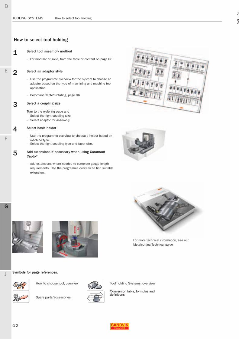
For more technical information, see our Metalcutting Technical guide
How to select tool holding
1 Select tool assembly method
- For modular or solid, from the table of content on page G6.
2 Select an adaptor style
- Use the programme overview for the system to choose an adaptor based on the type of machining and machine tool application.
- Coromant Capto®rotating, page G6
3 Select a coupling size
Turn to the ordering page and- Select the right coupling size- Select adaptor for assembly
4 Select basic holder
- Use the programme overview to choose a holder based on machine type.
- Select the right coupling type and taper size.
5 Add extensions if necessary when using Coromant Capto®
- Add extensions where needed to complete gauge length requirements. Use the programme overview to find suitable extension.
Symbols for page references:
How to choose tool, overview Tool holding Systems, overview
Spare parts/accessories
Conversion table, formulas and definitions
E
G 3
F
G
J
D
G
Content TOOLING SYSTEMS
RO
T -
EN
G
TOOLING SYSTEMS Content
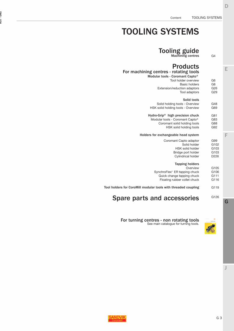
TOOLING SYSTEMS
Tooling guideMachining centres G4
ProductsFor machining centres - rotating tools
Modular tools - Coromant Capto®Tool holder overview G6
Basic holders G8Extension/reduction adaptors G26
Tool adaptors G29
Solid toolsSolid holding tools - Overview G48
HSK solid holding tools - Overview G69
Hydro-Grip® high precision chuck G81Modular tools - Coromant Capto® G83
Coromant solid holding tools G88HSK solid holding tools G92
Holders for exchangeable head system
Coromant Capto adaptor G99Solid holder G102
HSK solid holder G103Bridge port holder G103Cylindrical holder D226
Tapping holdersOverview G105
SynchroFlex® ER tapping chuck G106Quick change tapping chuck G111Floating rubber collet chuck G116
Tool holders for CoroMill modular tools with threaded coupling G119
Spare parts and accessories G126
For turning centres - non rotating toolsSee main catalogue for turning tools.
G 4
TOOLING SYSTEMS Coromant Capto®
E
F
G
J
D
G
RO
T - E
NG
TOOLING SYSTEMS Coromant Capto®
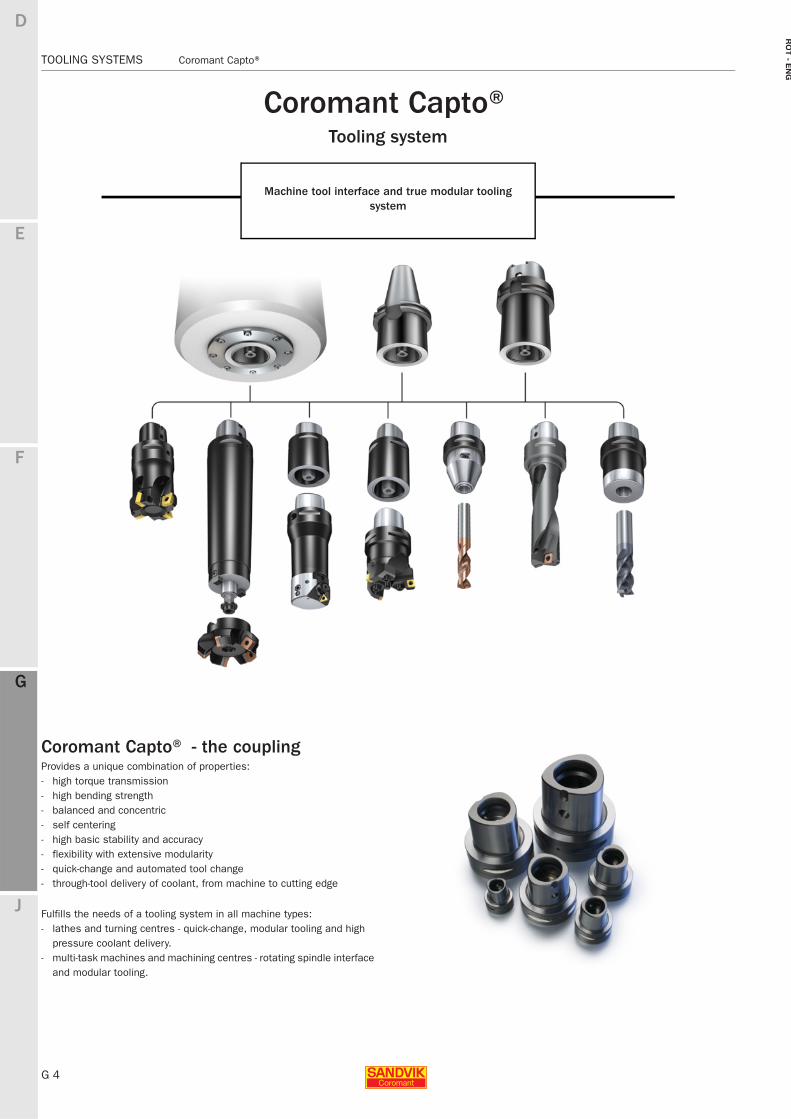
Coromant Capto® Tooling system
Machine tool interface and true modular tooling system
Coromant Capto® - the couplingProvides a unique combination of properties:- high torque transmission- high bending strength- balanced and concentric- self centering- high basic stability and accuracy- flexibility with extensive modularity- quick-change and automated tool change- through-tool delivery of coolant, from machine to cutting edge
Fulfills the needs of a tooling system in all machine types:- lathes and turning centres - quick-change, modular tooling and high
pressure coolant delivery.- multi-task machines and machining centres - rotating spindle interface
and modular tooling.
E
G 5
F
G
J
D
G
Coromant Capto® TOOLING SYSTEMS
RO
T -
EN
G
TOOLING SYSTEMS Coromant Capto®
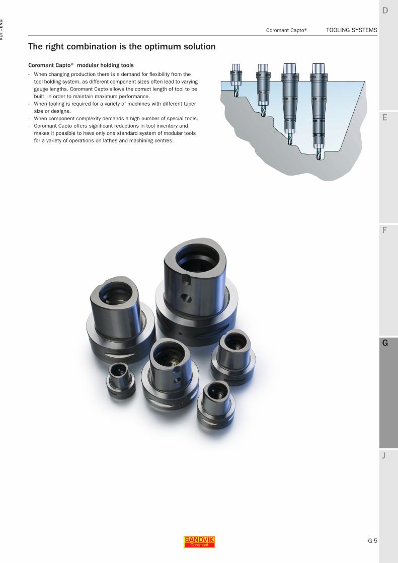
The right combination is the optimum solution
Coromant Capto® modular holding tools
- When changing production there is a demand for flexibility from the tool holding system, as different component sizes often lead to varying gauge lengths. Coromant Capto allows the correct length of tool to be built, in order to maintain maximum performance.
- When tooling is required for a variety of machines with different taper size or designs.
- When component complexity demands a high number of special tools.- Coromant Capto offers significant reductions in tool inventory and
makes it possible to have only one standard system of modular tools for a variety of operations on lathes and machining centres.
G 6
TOOLING SYSTEMS Coromant Capto® - Overview
E
F
G
J
D
G
RO
T - E
NG
TOOLING SYSTEMS Coromant Capto® − Overview
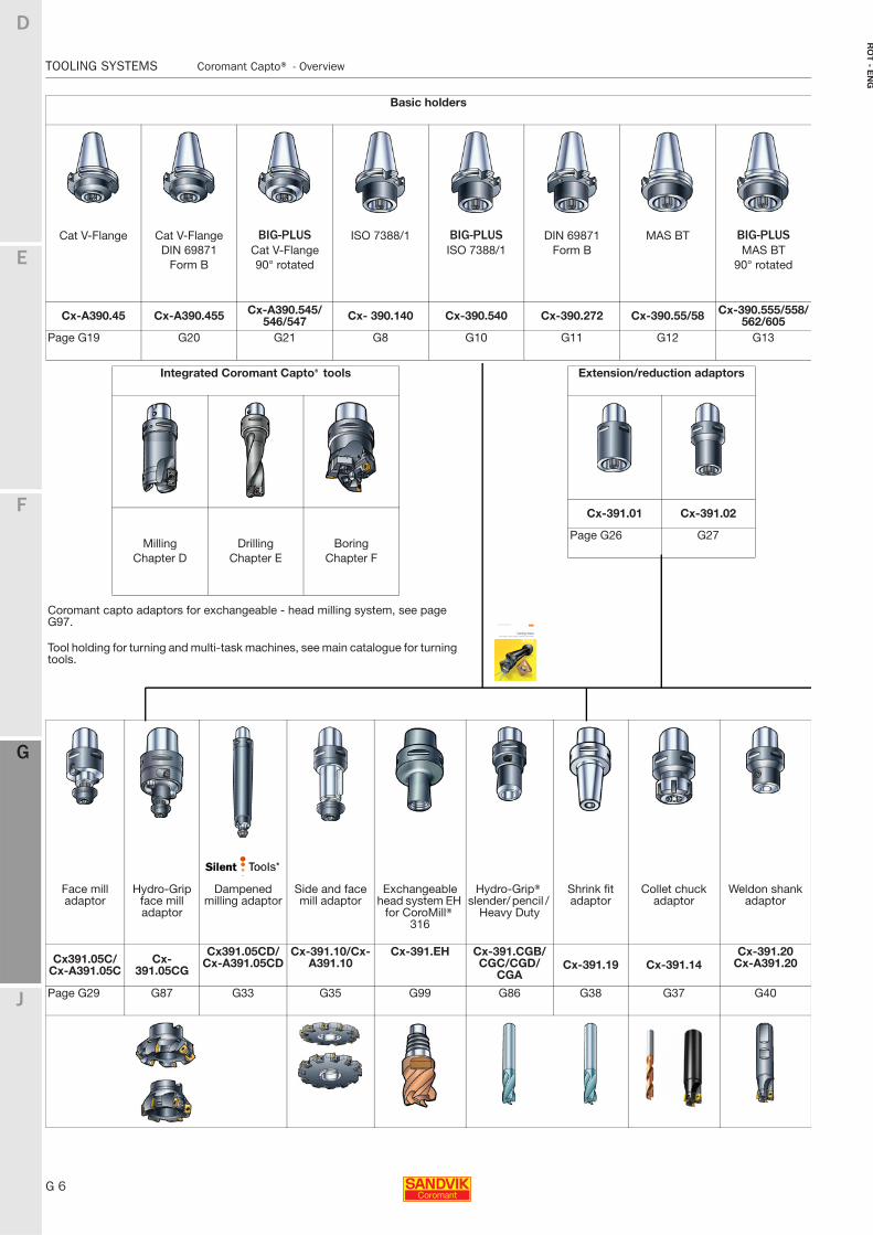
Basic holders
Cat V-Flange Cat V-Flange BIG-PLUS ISO 7388/1 BIG-PLUS DIN 69871 MAS BT BIG-PLUSDIN 69871 Cat V-Flange ISO 7388/1 Form B MAS BT
Form B 90° rotated 90° rotated
Cx-A390.45 Cx-A390.455 Cx-A390.545/546/547 Cx- 390.140 Cx-390.540 Cx-390.272 Cx-390.55/58 Cx-390.555/558/
562/605Page G19 G20 G21 G8 G10 G11 G12 G13
Integrated Coromant Capto® tools
Milling Drilling BoringChapter D Chapter E Chapter F
Extension/reduction adaptors
Cx-391.01 Cx-391.02
Page G26 G27
Coromant capto adaptors for exchangeable - head milling system, see page G97.
Tool holding for turning and multi-task machines, see main catalogue for turning tools.
Face mill adaptor
Hydro-Grip face mill adaptor
Dampened milling adaptor
Side and face mill adaptor
Exchangeable head system EH
for CoroMill® 316
Hydro-Grip® slender/ pencil /
Heavy Duty
Shrink fit adaptor
Collet chuck adaptor
Weldon shank adaptor
Cx391.05C/Cx-A391.05C
Cx-391.05CG
Cx391.05CD/Cx-A391.05CD
Cx-391.10/Cx-A391.10
Cx-391.EH Cx-391.CGB/CGC/CGD/
CGACx-391.19 Cx-391.14
Cx-391.20Cx-A391.20
Page G29 G87 G33 G35 G99 G86 G38 G37 G40
E
G 7
F
G
J
D
G
Coromant Capto® - Overview TOOLING SYSTEMS
RO
T -
EN
G
TOOLING SYSTEMS Coromant Capto® − Overview
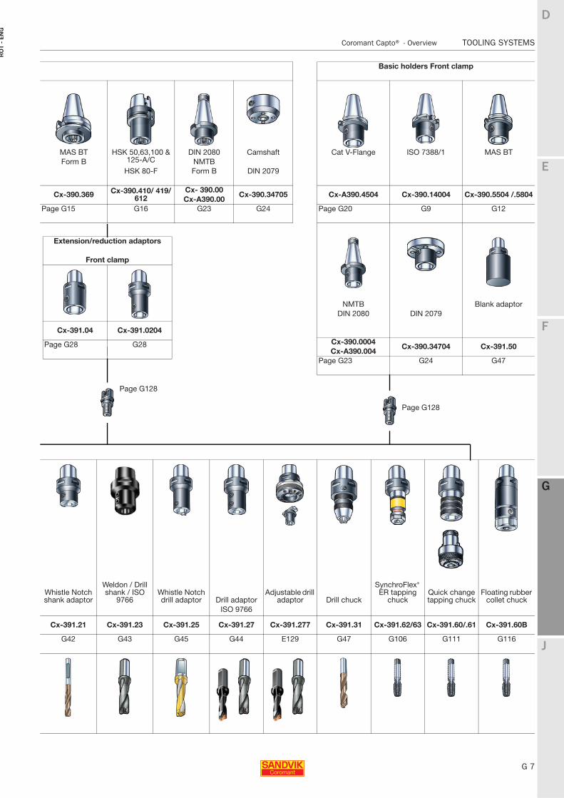
Basic holders Front clamp
MAS BT HSK 50,63,100 & 125-A/C
DIN 2080 Camshaft Cat V-Flange ISO 7388/1 MAS BTForm B NMTB
HSK 80-F Form B DIN 2079
Cx-390.369 Cx-390.410/ 419/ 612
Cx- 390.00Cx-390.34705 Cx-A390.4504 Cx-390.14004 Cx-390.5504 /.5804
Cx-A390.00Page G15 G16 G23 G24 Page G20 G9 G12
NMTB Blank adaptorDIN 2080 DIN 2079
Cx-390.0004Cx-390.34704 Cx-391.50
Cx-A390.004Page G23 G24 G47
Extension/reduction adaptors
Front clamp
Cx-391.04 Cx-391.0204
Page G28 G28
Whistle Notch shank adaptor
Weldon / Drill shank / ISO
9766Whistle Notch drill adaptor Drill adaptor
Adjustable drill adaptor Drill chuck
SynchroFlex® ER tapping
chuckQuick change tapping chuck
Floating rubber collet chuck
ISO 9766
Cx-391.21 Cx-391.23 Cx-391.25 Cx-391.27 Cx-391.277 Cx-391.31 Cx-391.62/63 Cx-391.60/.61 Cx-391.60B
G42 G43 G45 G44 E129 G47 G106 G111 G116
Page G128
Page G128
G 8
TOOLING SYSTEMS Coromant Capto® - Basic holders
E
F
G
J
D
G
RO
T - E
NG
TOOLING SYSTEMS Coromant Capto® − Basic holders
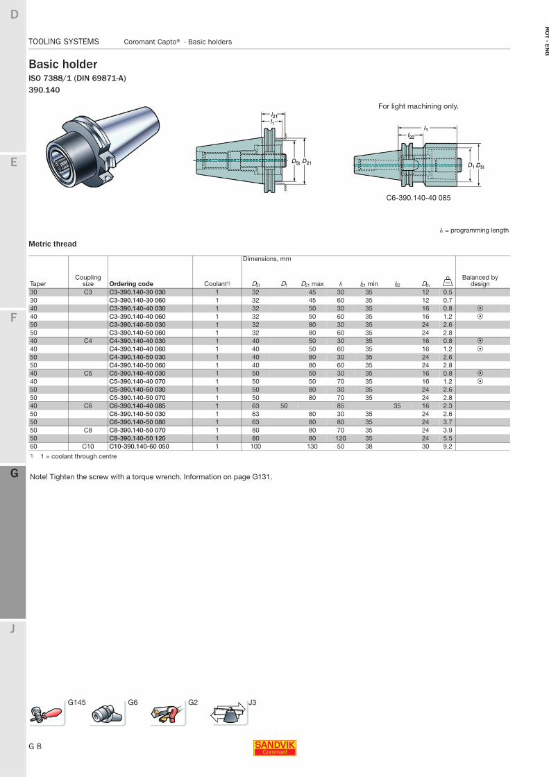
Basic holderISO 7388/1 (DIN 69871-A) 390.140
Metric thread
For light machining only.
C6-390.140-40 085
l1 = programming length
Dimensions, mm
TaperCoupling
size Ordering code Coolant1) D5t D1 D21 max l1 l21 min l22 Dth UBalanced by
design30 C3 C3-390.140-30 030 1 32 45 30 35 12 0.530 C3-390.140-30 060 1 32 45 60 35 12 0.740 C3-390.140-40 030 1 32 50 30 35 16 0.8 P40 C3-390.140-40 060 1 32 50 60 35 16 1.2 P50 C3-390.140-50 030 1 32 80 30 35 24 2.650 C3-390.140-50 060 1 32 80 60 35 24 2.840 C4 C4-390.140-40 030 1 40 50 30 35 16 0.8 P40 C4-390.140-40 060 1 40 50 60 35 16 1.2 P50 C4-390.140-50 030 1 40 80 30 35 24 2.650 C4-390.140-50 060 1 40 80 60 35 24 2.840 C5 C5-390.140-40 030 1 50 50 30 35 16 0.8 P40 C5-390.140-40 070 1 50 50 70 35 16 1.2 P50 C5-390.140-50 030 1 50 80 30 35 24 2.650 C5-390.140-50 070 1 50 80 70 35 24 2.840 C6 C6-390.140-40 085 1 63 50 85 35 16 2.350 C6-390.140-50 030 1 63 80 30 35 24 2.650 C6-390.140-50 080 1 63 80 80 35 24 3.750 C8 C8-390.140-50 070 1 80 80 70 35 24 3.950 C8-390.140-50 120 1 80 80 120 35 24 5.560 C10 C10-390.140-60 050 1 100 130 50 38 30 9.21) 1 = coolant through centre
Note! Tighten the screw with a torque wrench. Information on page G131.
G145 G6 G2 J3
E
G 9
F
G
J
D
G
Coromant Capto® - Basic holders TOOLING SYSTEMS
RO
T -
EN
G
TOOLING SYSTEMS Coromant Capto® − Basic holders
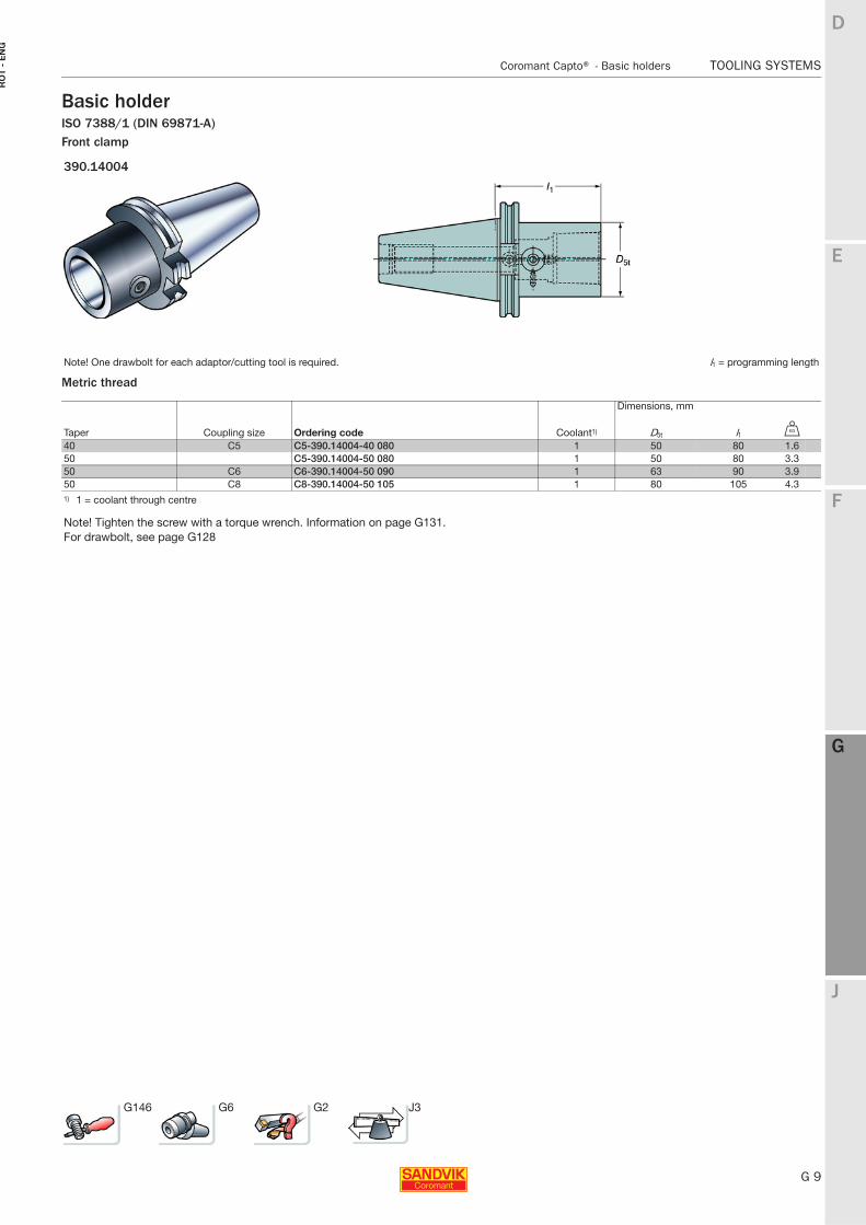
Basic holderISO 7388/1 (DIN 69871-A) Front clamp
Metric thread
390.14004
Note! One drawbolt for each adaptor/cutting tool is required. l1 = programming length
Dimensions, mm
Taper Coupling size Ordering code Coolant1) D5t l1 U
40 C5 C5-390.14004-40 080 1 50 80 1.650 C5-390.14004-50 080 1 50 80 3.350 C6 C6-390.14004-50 090 1 63 90 3.950 C8 C8-390.14004-50 105 1 80 105 4.31) 1 = coolant through centre
Note! Tighten the screw with a torque wrench. Information on page G131.For drawbolt, see page G128
G146 G6 G2 J3
G 10
TOOLING SYSTEMS Coromant Capto® - Basic holders
E
F
G
J
D
G
RO
T - E
NG
TOOLING SYSTEMS Coromant Capto® − Basic holders
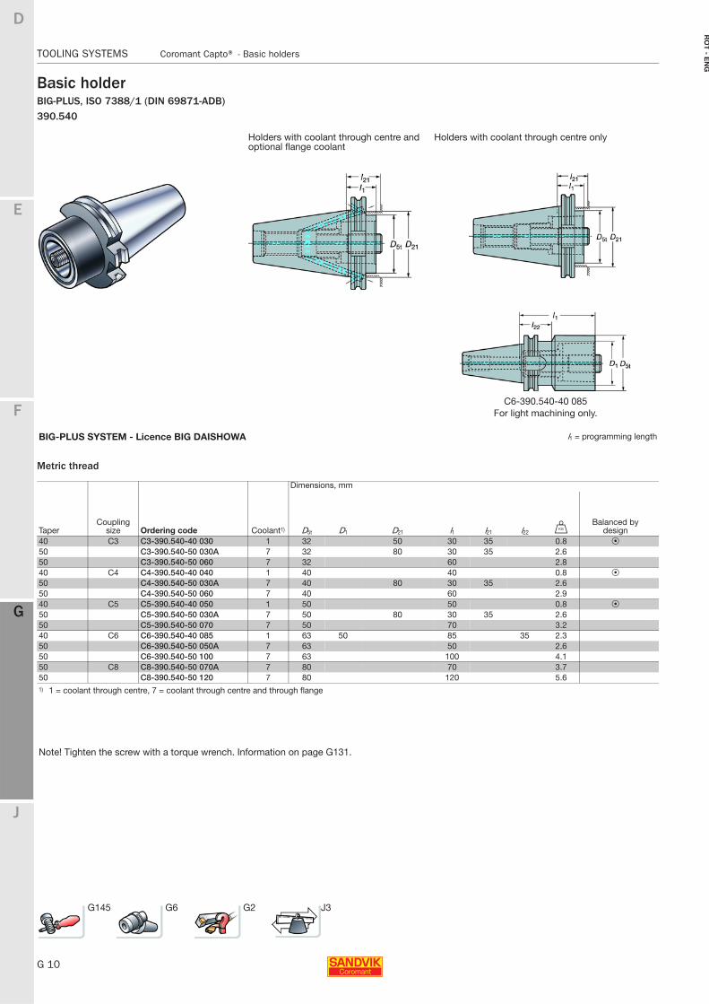
Basic holderBIG-PLUS, ISO 7388/1 (DIN 69871-ADB)390.540
Metric thread
Holders with coolant through centre and optional flange coolant
Holders with coolant through centre only
C6-390.540-40 085For light machining only.
BIG-PLUS SYSTEM - Licence BIG DAISHOWA l1 = programming length
Dimensions, mm
TaperCoupling
size Ordering code Coolant1) D5t D1 D21 l1 l21 l22 UBalanced by
design40 C3 C3-390.540-40 030 1 32 50 30 35 0.8 P50 C3-390.540-50 030A 7 32 80 30 35 2.650 C3-390.540-50 060 7 32 60 2.840 C4 C4-390.540-40 040 1 40 40 0.8 P50 C4-390.540-50 030A 7 40 80 30 35 2.650 C4-390.540-50 060 7 40 60 2.940 C5 C5-390.540-40 050 1 50 50 0.8 P50 C5-390.540-50 030A 7 50 80 30 35 2.650 C5-390.540-50 070 7 50 70 3.240 C6 C6-390.540-40 085 1 63 50 85 35 2.350 C6-390.540-50 050A 7 63 50 2.650 C6-390.540-50 100 7 63 100 4.150 C8 C8-390.540-50 070A 7 80 70 3.750 C8-390.540-50 120 7 80 120 5.61) 1 = coolant through centre, 7 = coolant through centre and through flange
Note! Tighten the screw with a torque wrench. Information on page G131.
G145 G6 G2 J3
E
G 11
F
G
J
D
G
Coromant Capto® - Basic holders TOOLING SYSTEMS
RO
T -
EN
G
TOOLING SYSTEMS Coromant Capto® − Basic holders
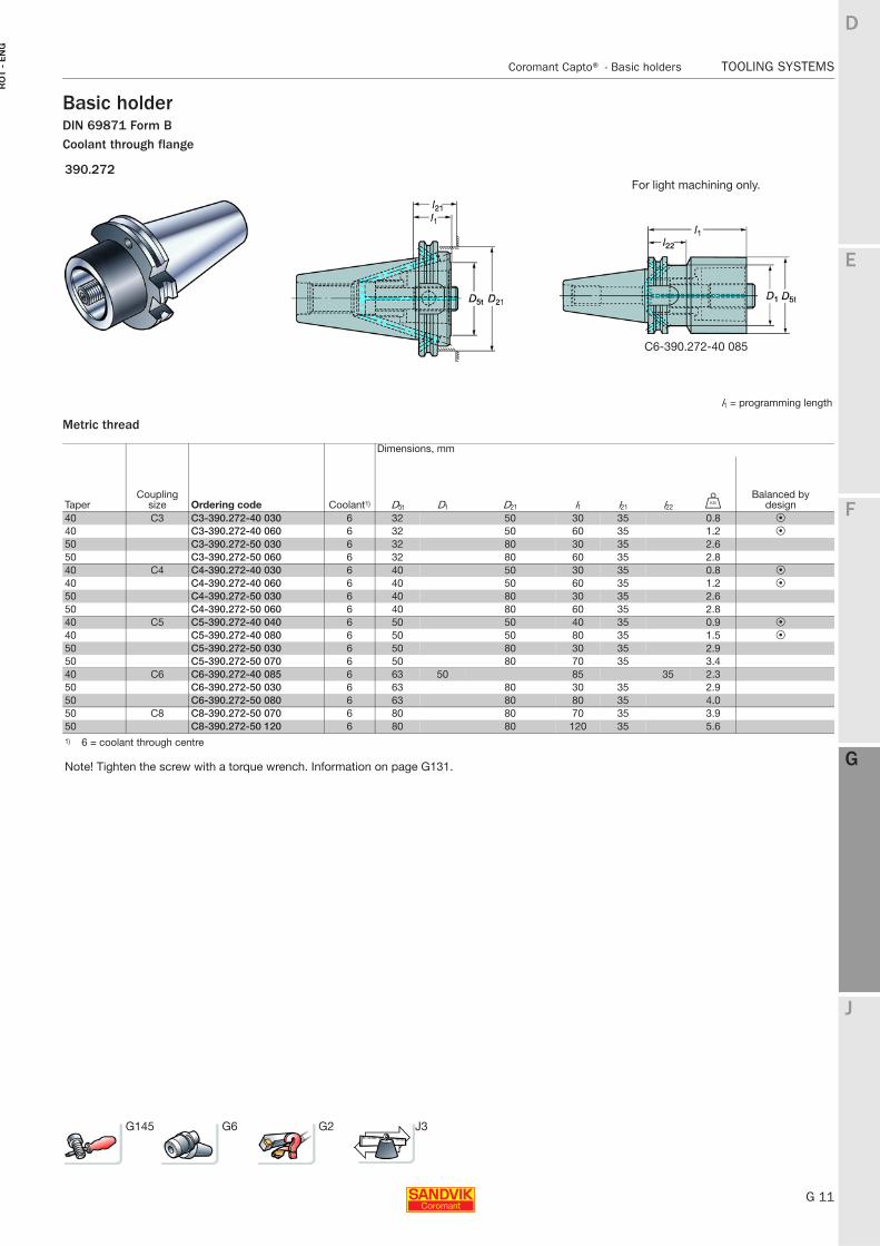
Basic holderDIN 69871 Form BCoolant through flange
Metric thread
390.272For light machining only.
C6-390.272-40 085
l1 = programming length
Dimensions, mm
TaperCoupling
size Ordering code Coolant1) D5t D1 D21 l1 l21 l22 UBalanced by
design40 C3 C3-390.272-40 030 6 32 50 30 35 0.8 P40 C3-390.272-40 060 6 32 50 60 35 1.2 P50 C3-390.272-50 030 6 32 80 30 35 2.650 C3-390.272-50 060 6 32 80 60 35 2.840 C4 C4-390.272-40 030 6 40 50 30 35 0.8 P40 C4-390.272-40 060 6 40 50 60 35 1.2 P50 C4-390.272-50 030 6 40 80 30 35 2.650 C4-390.272-50 060 6 40 80 60 35 2.840 C5 C5-390.272-40 040 6 50 50 40 35 0.9 P40 C5-390.272-40 080 6 50 50 80 35 1.5 P50 C5-390.272-50 030 6 50 80 30 35 2.950 C5-390.272-50 070 6 50 80 70 35 3.440 C6 C6-390.272-40 085 6 63 50 85 35 2.350 C6-390.272-50 030 6 63 80 30 35 2.950 C6-390.272-50 080 6 63 80 80 35 4.050 C8 C8-390.272-50 070 6 80 80 70 35 3.950 C8-390.272-50 120 6 80 80 120 35 5.61) 6 = coolant through centre
Note! Tighten the screw with a torque wrench. Information on page G131.
G145 G6 G2 J3
G 12
TOOLING SYSTEMS Coromant Capto® - Basic holders
E
F
G
J
D
G
RO
T - E
NG
TOOLING SYSTEMS Coromant Capto® − Basic holders
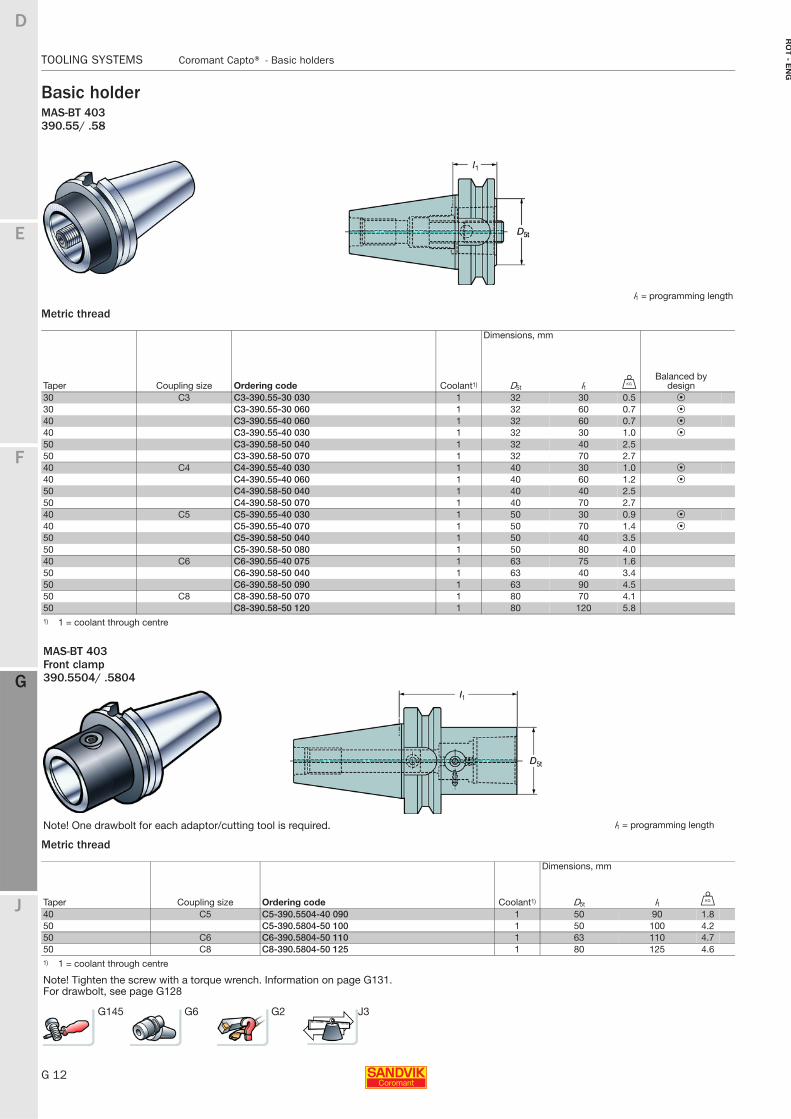
Basic holderMAS-BT 403390.55/ .58
Metric thread
Metric thread
l1 = programming length
Dimensions, mm
Taper Coupling size Ordering code Coolant1) D5t l1 UBalanced by
design30 C3 C3-390.55-30 030 1 32 30 0.5 P30 C3-390.55-30 060 1 32 60 0.7 P40 C3-390.55-40 060 1 32 60 0.7 P40 C3-390.55-40 030 1 32 30 1.0 P50 C3-390.58-50 040 1 32 40 2.550 C3-390.58-50 070 1 32 70 2.740 C4 C4-390.55-40 030 1 40 30 1.0 P40 C4-390.55-40 060 1 40 60 1.2 P50 C4-390.58-50 040 1 40 40 2.550 C4-390.58-50 070 1 40 70 2.740 C5 C5-390.55-40 030 1 50 30 0.9 P40 C5-390.55-40 070 1 50 70 1.4 P50 C5-390.58-50 040 1 50 40 3.550 C5-390.58-50 080 1 50 80 4.040 C6 C6-390.55-40 075 1 63 75 1.650 C6-390.58-50 040 1 63 40 3.450 C6-390.58-50 090 1 63 90 4.550 C8 C8-390.58-50 070 1 80 70 4.150 C8-390.58-50 120 1 80 120 5.81) 1 = coolant through centre
MAS-BT 403Front clamp390.5504/ .5804
Note! One drawbolt for each adaptor/cutting tool is required. l1 = programming length
Dimensions, mm
Taper Coupling size Ordering code Coolant1) D5t l1 U
40 C5 C5-390.5504-40 090 1 50 90 1.850 C5-390.5804-50 100 1 50 100 4.250 C6 C6-390.5804-50 110 1 63 110 4.750 C8 C8-390.5804-50 125 1 80 125 4.61) 1 = coolant through centre
Note! Tighten the screw with a torque wrench. Information on page G131.For drawbolt, see page G128
G145 G6 G2 J3
E
G 13
F
G
J
D
G
Coromant Capto® - Basic holders TOOLING SYSTEMS
RO
T -
EN
G
TOOLING SYSTEMS Coromant Capto® − Basic holders
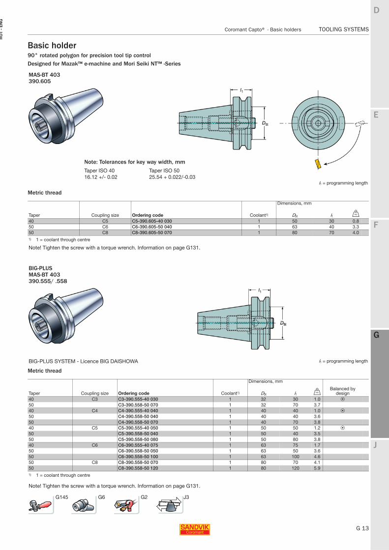
Basic holder90° rotated polygon for precision tool tip controlDesigned for Mazak™ e-machine and Mori Seiki NT™ -Series
Metric thread
Metric thread
MAS-BT 403390.605
l1 = programming length
Dimensions, mm
Taper Coupling size Ordering code Coolant1) D5t l1 U
40 C5 C5-390.605-40 030 1 50 30 0.850 C6 C6-390.605-50 040 1 63 40 3.350 C8 C8-390.605-50 070 1 80 70 4.01) 1 = coolant through centre
Note! Tighten the screw with a torque wrench. Information on page G131.
BIG-PLUSMAS-BT 403390.555/ .558
BIG-PLUS SYSTEM - Licence BIG DAISHOWA l1 = programming length
Dimensions, mm
Taper Coupling size Ordering code Coolant1) D5t l1 UBalanced by
design40 C3 C3-390.555-40 030 1 32 30 1.0 P50 C3-390.558-50 070 1 32 70 3.740 C4 C4-390.555-40 040 1 40 40 1.0 P50 C4-390.558-50 040 1 40 40 3.650 C4-390.558-50 070 1 40 70 3.840 C5 C5-390.555-40 050 1 50 50 1.2 P50 C5-390.558-50 040 1 50 40 3.550 C5-390.558-50 080 1 50 80 3.840 C6 C6-390.555-40 075 1 63 75 1.750 C6-390.558-50 050 1 63 50 3.650 C6-390.558-50 100 1 63 100 4.650 C8 C8-390.558-50 070 1 80 70 4.150 C8-390.558-50 120 1 80 120 5.91) 1 = coolant through centre
Note! Tighten the screw with a torque wrench. Information on page G131.
Note: Tolerances for key way width, mm
Taper ISO 40 Taper ISO 5016.12 +/- 0.02 25.54 + 0.022/-0.03
G145 G6 G2 J3
G 14
TOOLING SYSTEMS Coromant Capto® - Basic holders
E
F
G
J
D
G
RO
T - E
NG
TOOLING SYSTEMS Coromant Capto® − Basic holders
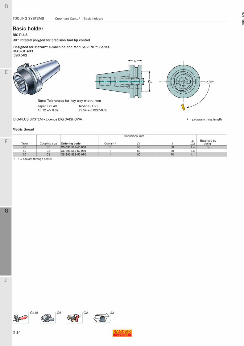
Basic holderBIG-PLUS90° rotated polygon for precision tool tip control
Metric thread
Designed for Mazak™ e-machine and Mori Seiki NT™ -SeriesMAS-BT 403390.562
BIG-PLUS SYSTEM - Licence BIG DAISHOWA l1 = programming length
Dimensions, mm
Taper Coupling size Ordering code Coolant1) D5t l1 UBalanced by
design40 C5 C5-390.562-40 050 1 50 50 1.4 P50 C6 C6-390.562-50 050 1 63 50 3.650 C8 C8-390.562-50 070 1 80 70 4.1
1) 1 = coolant through centre
G145 G6 G2 J3
Note: Tolerances for key way width, mm
Taper ISO 40 Taper ISO 5016.12 +/- 0.02 25.54 + 0.022/-0.03
E
G 15
F
G
J
D
G
Coromant Capto® - Basic holders TOOLING SYSTEMS
RO
T -
EN
G
TOOLING SYSTEMS Coromant Capto® − Basic holders
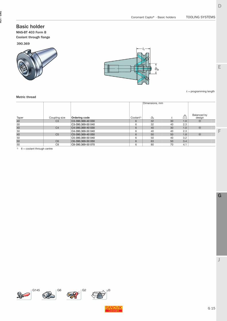
Basic holderMAS-BT 403 Form BCoolant through flange
Metric thread
390.369
l1 = programming length
Dimensions, mm
Taper Coupling size Ordering code Coolant1) D5t l1 UBalanced by
design40 C3 C3-390.369-40 030 6 32 30 1.0 P50 C3-390.369-50 040 6 32 40 2.340 C4 C4-390.369-40 030 6 40 30 1.0 P50 C4-390.369-50 040 6 40 40 2.340 C5 C5-390.369-40 050 6 50 50 1.8 P50 C5-390.369-50 040 6 50 40 3.250 C6 C6-390.369-50 050 6 63 50 3.450 C8 C8-390.369-50 070 6 80 70 4.11) 6 = coolant through centre
G145 G6 G2 J3
G 16
TOOLING SYSTEMS Coromant Capto® - Basic holders
E
F
G
J
D
G
RO
T - E
NG
TOOLING SYSTEMS Coromant Capto® − Basic holders
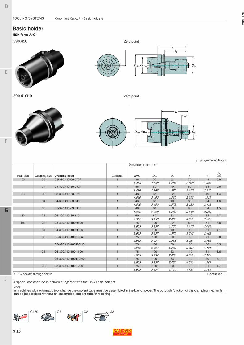
Basic holderHSK form A/C
390.410 Zero point
390.410HD Zero point
l1 = programming length
Dimensions, mm, inch
HSK size Coupling size Ordering code Coolant1) dmm D5m D5t l1 l3 U
50 C3 C3-390.410-50 075A 1 38 50 32 75 49 0.61.496 1.968 1.260 2.953 1.929
C4 C4-390.410-50 080A 1 38 50 40 80 54 0.81.496 1.968 1.575 3.150 2.126
63 C3 C3-390.410-63 075C 1 48 63 32 75 49 1.41.890 2.480 1.260 2.953 1.929
C4 C4-390.410-63 080C 1 48 63 40 80 54 1.61.890 2.480 1.575 3.150 2.126
C5 C5-390.410-63 090C 1 48 63 50 90 64 1.51.890 2.480 1.968 3.543 2.520
80 C6 C6-390.410-80 110 1 60 80 63 110 84 2.72.362 3.150 2.480 4.331 3.307
100 C3 C3-390.410-100 080A 1 75 100 32 80 51 3.82.953 3.937 1.260 3.150 2.008
C4 C4-390.410-100 090A 1 75 100 40 90 61 4.12.953 3.937 1.575 3.543 2.402
C5 C5-390.410-100 100A 1 75 100 50 100 71 3.02.953 3.937 1.968 3.937 2.795
C5-390.410-100100HD 1 75 100 50 100 30 3.52.953 3.937 1.968 3.937 1.181
C6 C6-390.410-100 110A 1 75 100 63 110 81 3.62.953 3.937 2.480 4.331 3.189
C6-390.410-100110HD 1 75 100 63 110 30 4.12.953 3.937 2.480 4.331 1.181
C8 C8-390.410-100 120A 1 75 100 80 120 91 4.72.953 3.937 3.150 4.724 3.583
1) 1 = coolant through centre Continued ...
A special coolant tube is delivered together with the HSK basic holders.
Note!In machines with automatic tool change the coolant tube must be assembled in the basic holder. The outpush function of the clamping mechanism can be jeopardized without an assembled coolant tube/thread ring.
G170 G6 G2 J3
E
G 17
F
G
J
D
G
Coromant Capto® - Basic holders TOOLING SYSTEMS
RO
T -
EN
G
TOOLING SYSTEMS Coromant Capto® − Basic holders
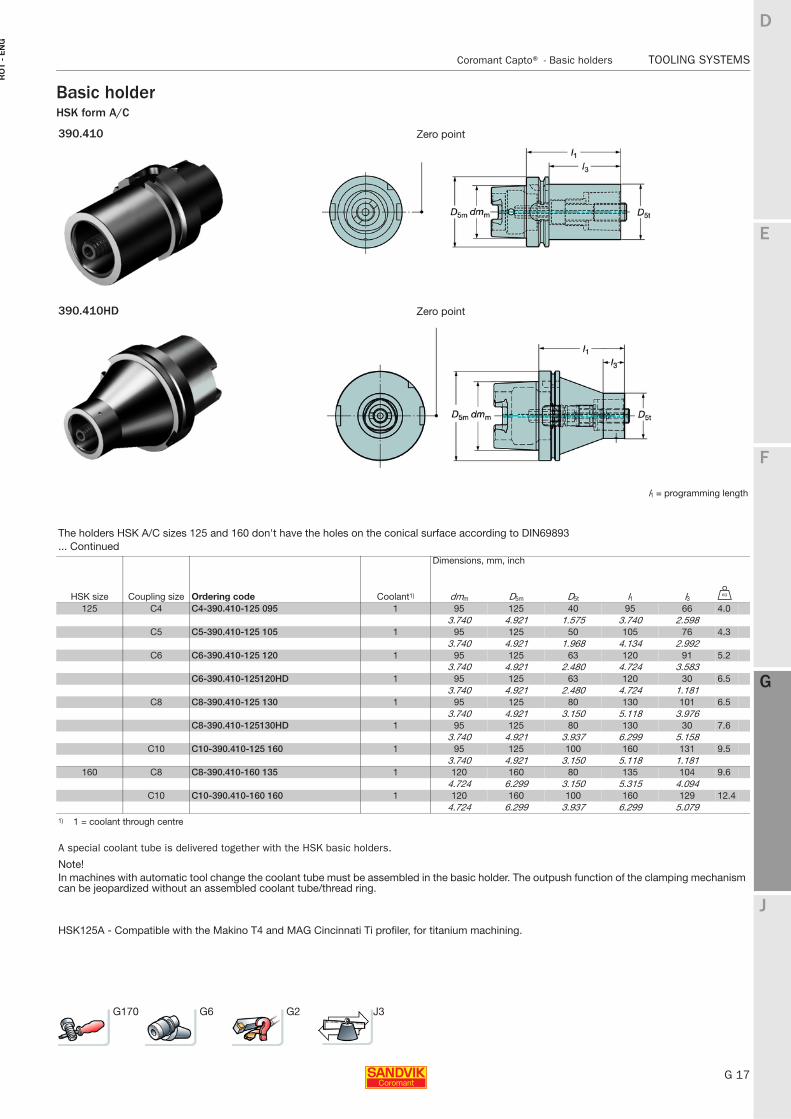
Basic holderHSK form A/C
390.410 Zero point
390.410HD Zero point
l1 = programming length
The holders HSK A/C sizes 125 and 160 don't have the holes on the conical surface according to DIN69893... Continued
Dimensions, mm, inch
HSK size Coupling size Ordering code Coolant1) dmm D5m D5t l1 l3 U
125 C4 C4-390.410-125 095 1 95 125 40 95 66 4.03.740 4.921 1.575 3.740 2.598
C5 C5-390.410-125 105 1 95 125 50 105 76 4.33.740 4.921 1.968 4.134 2.992
C6 C6-390.410-125 120 1 95 125 63 120 91 5.23.740 4.921 2.480 4.724 3.583
C6-390.410-125120HD 1 95 125 63 120 30 6.53.740 4.921 2.480 4.724 1.181
C8 C8-390.410-125 130 1 95 125 80 130 101 6.53.740 4.921 3.150 5.118 3.976
C8-390.410-125130HD 1 95 125 80 130 30 7.63.740 4.921 3.937 6.299 5.158
C10 C10-390.410-125 160 1 95 125 100 160 131 9.53.740 4.921 3.150 5.118 1.181
160 C8 C8-390.410-160 135 1 120 160 80 135 104 9.64.724 6.299 3.150 5.315 4.094
C10 C10-390.410-160 160 1 120 160 100 160 129 12.44.724 6.299 3.937 6.299 5.079
1) 1 = coolant through centre
A special coolant tube is delivered together with the HSK basic holders.
Note!In machines with automatic tool change the coolant tube must be assembled in the basic holder. The outpush function of the clamping mechanism can be jeopardized without an assembled coolant tube/thread ring.
HSK125A - Compatible with the Makino T4 and MAG Cincinnati Ti profiler, for titanium machining.
G170 G6 G2 J3
G 18
TOOLING SYSTEMS Coromant Capto® - Basic holders
E
F
G
J
D
G
RO
T - E
NG
TOOLING SYSTEMS Coromant Capto® − Basic holders
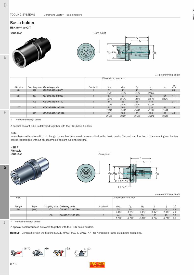
Basic holderHSK form A/C/T
HSK80F - Compatible with the Makino MAG1, MAG3, MAG4, MAG7, A7 - for Aerospace frame aluminium machining.
390.419 Zero point
l1 = programming length
Dimensions, mm, inch
HSK size Coupling size Ordering code Coolant1) dmm D5m D5t l1 l3 U
40 C4 C4-390.419-40 075 1 28 40 40 75 0.61.102 1.575 1.575 2.953
63 C5 C5-390.419-63 090 1 35 63 50 90 64 1.41.378 2.480 1.968 3.543 2.520
C6 C6-390.419-63 110 1 44 63 63 110 2.11.732 2.480 2.480 4.331
100 C6 C6-390.419-100 110 1 44 100 63 110 81 3.61.732 3.937 2.480 4.331 3.189
C8 C8-390.419-100 120 1 55 100 80 120 91 4.82.165 3.937 3.150 4.724 3.583
1) 1 = coolant through centre
A special coolant tube is delivered together with the HSK basic holders.
Note!In machines with automatic tool change the coolant tube must be assembled in the basic holder. The outpush function of the clamping mechanism can be jeopardized without an assembled coolant tube/thread ring.
HSK FPin style390.612 Zero point
l1 = programming length
HSK Dimensions, mm, inch
Flange Taper Coupling size Ordering code Coolant1) dmm D5m D5t l1 l3 U
80 ( 63 ) C5 C5-390.612-80 090 1 35 80 50 90 64 1.91.378 3.150 1.968 3.543 2.520 1.9
C6 C6-390.612-80 105 1 44 80 63 105 79 2.61.732 3.150 2.480 4.134 3.110 2.6
1) 1 = coolant through centre
A special coolant tube is delivered together with the HSK basic holders.
G170 G6 G2 J3
E
G 19
F
G
J
D
G
Coromant Capto® - Basic holders TOOLING SYSTEMS
RO
T -
EN
G
TOOLING SYSTEMS Coromant Capto® − Basic holders
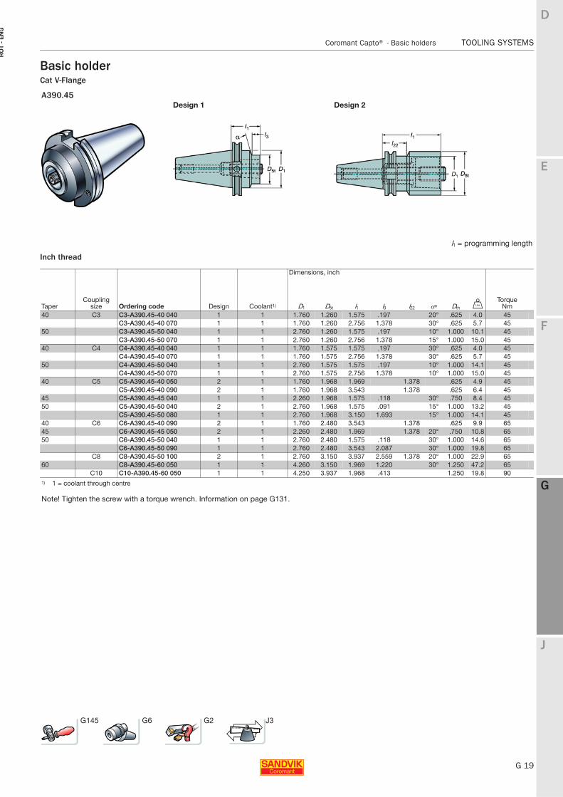
Basic holderCat V-Flange
Inch thread
A390.45Design 1 Design 2
l1 = programming length
Dimensions, inch
TaperCoupling
size Ordering code Design Coolant1) D1 D5t l1 l3 l22 αo Dth VTorque
Nm40 C3 C3-A390.45-40 040 1 1 1.760 1.260 1.575 .197 20° .625 4.0 45
C3-A390.45-40 070 1 1 1.760 1.260 2.756 1.378 30° .625 5.7 4550 C3-A390.45-50 040 1 1 2.760 1.260 1.575 .197 10° 1.000 10.1 45
C3-A390.45-50 070 1 1 2.760 1.260 2.756 1.378 15° 1.000 15.0 4540 C4 C4-A390.45-40 040 1 1 1.760 1.575 1.575 .197 30° .625 4.0 45
C4-A390.45-40 070 1 1 1.760 1.575 2.756 1.378 30° .625 5.7 4550 C4-A390.45-50 040 1 1 2.760 1.575 1.575 .197 10° 1.000 14.1 45
C4-A390.45-50 070 1 1 2.760 1.575 2.756 1.378 10° 1.000 15.0 4540 C5 C5-A390.45-40 050 2 1 1.760 1.968 1.969 1.378 .625 4.9 45
C5-A390.45-40 090 2 1 1.760 1.968 3.543 1.378 .625 6.4 4545 C5-A390.45-45 040 1 1 2.260 1.968 1.575 .118 30° .750 8.4 4550 C5-A390.45-50 040 2 1 2.760 1.968 1.575 .091 15° 1.000 13.2 45
C5-A390.45-50 080 1 1 2.760 1.968 3.150 1.693 15° 1.000 14.1 4540 C6 C6-A390.45-40 090 2 1 1.760 2.480 3.543 1.378 .625 9.9 6545 C6-A390.45-45 050 2 1 2.260 2.480 1.969 1.378 20° .750 10.8 6550 C6-A390.45-50 040 1 1 2.760 2.480 1.575 .118 30° 1.000 14.6 65
C6-A390.45-50 090 1 1 2.760 2.480 3.543 2.087 30° 1.000 19.8 65C8 C8-A390.45-50 100 2 1 2.760 3.150 3.937 2.559 1.378 20° 1.000 22.9 65
60 C8-A390.45-60 050 1 1 4.260 3.150 1.969 1.220 30° 1.250 47.2 65C10 C10-A390.45-60 050 1 1 4.250 3.937 1.968 .413 1.250 19.8 90
1) 1 = coolant through centre
Note! Tighten the screw with a torque wrench. Information on page G131.
G145 G6 G2 J3
G 20
TOOLING SYSTEMS Coromant Capto® - Basic holders
E
F
G
J
D
G
RO
T - E
NG
TOOLING SYSTEMS Coromant Capto® − Basic holders
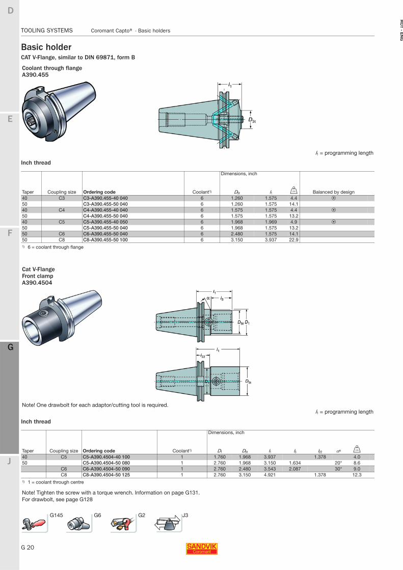
Basic holderCAT V-Flange, similar to DIN 69871, form B
Inch thread
Inch thread
Coolant through flangeA390.455
l1 = programming length
Dimensions, inch
Taper Coupling size Ordering code Coolant1) D5t l1 V Balanced by design40 C3 C3-A390.455-40 040 6 1.260 1.575 4.4 P50 C3-A390.455-50 040 6 1.260 1.575 14.140 C4 C4-A390.455-40 040 6 1.575 1.575 4.4 P50 C4-A390.455-50 040 6 1.575 1.575 13.240 C5 C5-A390.455-40 050 6 1.968 1.969 4.9 P50 C5-A390.455-50 040 6 1.968 1.575 13.250 C6 C6-A390.455-50 040 6 2.480 1.575 14.150 C8 C8-A390.455-50 100 6 3.150 3.937 22.91) 6 = coolant through flange
Cat V-FlangeFront clampA390.4504
Note! One drawbolt for each adaptor/cutting tool is required.l1 = programming length
Dimensions, inch
Taper Coupling size Ordering code Coolant1) D1 D5t l1 l3 l22 αo V
40 C5 C5-A390.4504-40 100 1 1.760 1.968 3.937 1.378 4.050 C5-A390.4504-50 080 1 2.760 1.968 3.150 1.634 20° 8.6
C6 C6-A390.4504-50 090 1 2.760 2.480 3.543 2.087 30° 9.0C8 C8-A390.4504-50 125 1 2.760 3.150 4.921 1.378 12.3
1) 1 = coolant through centre
Note! Tighten the screw with a torque wrench. Information on page G131.For drawbolt, see page G128
G145 G6 G2 J3
E
G 21
F
G
J
D
G
Coromant Capto® - Basic holders TOOLING SYSTEMS
RO
T -
EN
G
TOOLING SYSTEMS Coromant Capto® − Basic holders
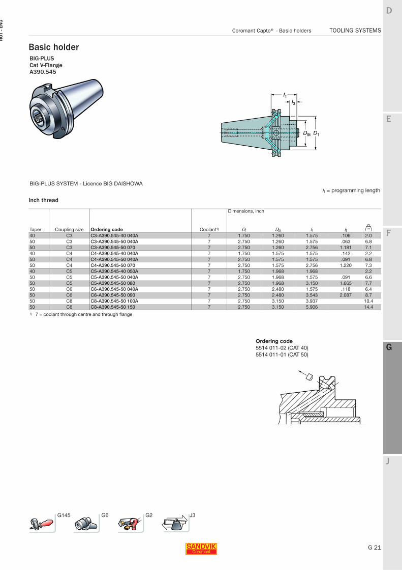
Basic holder
Inch thread
BIG-PLUSCat V-FlangeA390.545
BIG-PLUS SYSTEM - Licence BIG DAISHOWAl1 = programming length
Dimensions, inch
Taper Coupling size Ordering code Coolant1) D1 D5t l1 l3 V
40 C3 C3-A390.545-40 040A 7 1.750 1.260 1.575 .106 2.050 C3 C3-A390.545-50 040A 7 2.750 1.260 1.575 .063 6.850 C3 C3-A390.545-50 070 7 2.750 1.260 2.756 1.181 7.140 C4 C4-A390.545-40 040A 7 1.750 1.575 1.575 .142 2.250 C4 C4-A390.545-50 040A 7 2.750 1.575 1.575 .091 6.850 C4 C4-A390.545-50 070 7 2.750 1.575 2.756 1.220 7.340 C5 C5-A390.545-40 050A 7 1.750 1.968 1.968 2.250 C5 C5-A390.545-50 040A 7 2.750 1.968 1.575 .091 6.650 C5 C5-A390.545-50 080 7 2.750 1.968 3.150 1.665 7.750 C6 C6-A390.545-50 040A 7 2.750 2.480 1.575 .118 6.450 C6 C6-A390.545-50 090 7 2.750 2.480 3.543 2.087 8.750 C8 C8-A390.545-50 100A 7 2.750 3.150 3.937 10.450 C8 C8-A390.545-50 150 7 2.750 3.150 5.906 14.41) 7 = coolant through centre and through flange
G145 G6 G2 J3
Ordering code5514 011-02 (CAT 40)5514 011-01 (CAT 50)
G 22
TOOLING SYSTEMS Coromant Capto® - Basic holders
E
F
G
J
D
G
RO
T - E
NG
TOOLING SYSTEMS Coromant Capto® − Basic holders
Basic holder
Inch thread
Inch thread
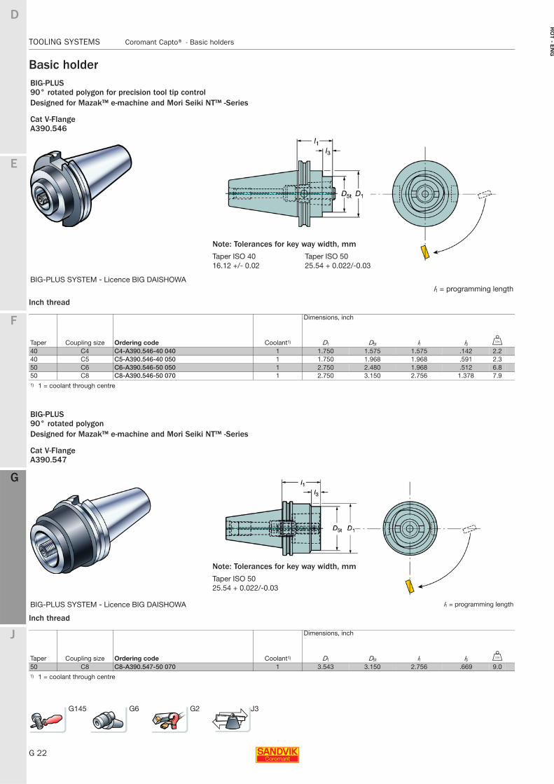
BIG-PLUS90° rotated polygon for precision tool tip controlDesigned for Mazak™ e-machine and Mori Seiki NT™ -Series
Cat V-FlangeA390.546
BIG-PLUS SYSTEM - Licence BIG DAISHOWAl1 = programming length
Dimensions, inch
Taper Coupling size Ordering code Coolant1) D1 D5t l1 l3 V
40 C4 C4-A390.546-40 040 1 1.750 1.575 1.575 .142 2.240 C5 C5-A390.546-40 050 1 1.750 1.968 1.968 .591 2.350 C6 C6-A390.546-50 050 1 2.750 2.480 1.968 .512 6.850 C8 C8-A390.546-50 070 1 2.750 3.150 2.756 1.378 7.91) 1 = coolant through centre
BIG-PLUS90° rotated polygonDesigned for Mazak™ e-machine and Mori Seiki NT™ -Series
Cat V-FlangeA390.547
BIG-PLUS SYSTEM - Licence BIG DAISHOWA l1 = programming length
Dimensions, inch
Taper Coupling size Ordering code Coolant1) D1 D5t l1 l3 V
50 C8 C8-A390.547-50 070 1 3.543 3.150 2.756 .669 9.01) 1 = coolant through centre
G145 G6 G2 J3
Note: Tolerances for key way width, mm
Taper ISO 40 Taper ISO 5016.12 +/- 0.02 25.54 + 0.022/-0.03
Note: Tolerances for key way width, mm
Taper ISO 5025.54 + 0.022/-0.03
E
G 23
F
G
J
D
G
Coromant Capto® - Basic holders TOOLING SYSTEMS
RO
T -
EN
G
TOOLING SYSTEMS Coromant Capto® − Basic holders
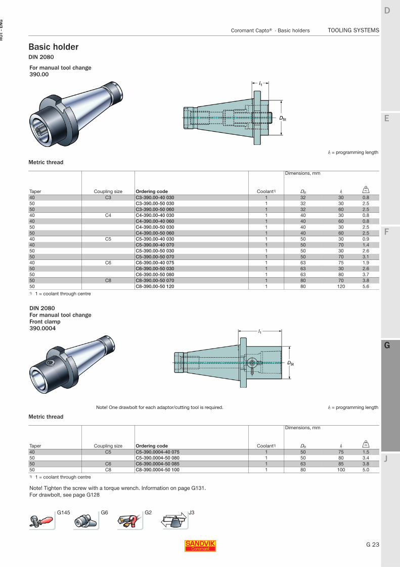
Basic holderDIN 2080
Metric thread
Metric thread
For manual tool change390.00
l1 = programming length
Dimensions, mm
Taper Coupling size Ordering code Coolant1) D5t l1 U
40 C3 C3-390.00-40 030 1 32 30 0.850 C3-390.00-50 030 1 32 30 2.550 C3-390.00-50 060 1 32 60 2.540 C4 C4-390.00-40 030 1 40 30 0.840 C4-390.00-40 060 1 40 60 0.850 C4-390.00-50 030 1 40 30 2.550 C4-390.00-50 060 1 40 60 2.540 C5 C5-390.00-40 030 1 50 30 0.940 C5-390.00-40 070 1 50 70 1.450 C5-390.00-50 030 1 50 30 2.650 C5-390.00-50 070 1 50 70 3.140 C6 C6-390.00-40 075 1 63 75 1.950 C6-390.00-50 030 1 63 30 2.650 C6-390.00-50 080 1 63 80 3.750 C8 C8-390.00-50 070 1 80 70 3.850 C8-390.00-50 120 1 80 120 5.61) 1 = coolant through centre
DIN 2080For manual tool changeFront clamp390.0004
Note! One drawbolt for each adaptor/cutting tool is required. l1 = programming length
Dimensions, mm
Taper Coupling size Ordering code Coolant1) D5t l1 U
40 C5 C5-390.0004-40 075 1 50 75 1.550 C5-390.0004-50 080 1 50 80 3.450 C6 C6-390.0004-50 085 1 63 85 3.850 C8 C8-390.0004-50 100 1 80 100 5.01) 1 = coolant through centre
Note! Tighten the screw with a torque wrench. Information on page G131.For drawbolt, see page G128
G145 G6 G2 J3
G 24
TOOLING SYSTEMS Coromant Capto® - Basic holders
E
F
G
J
D
G
RO
T - E
NG
TOOLING SYSTEMS Coromant Capto® − Basic holders
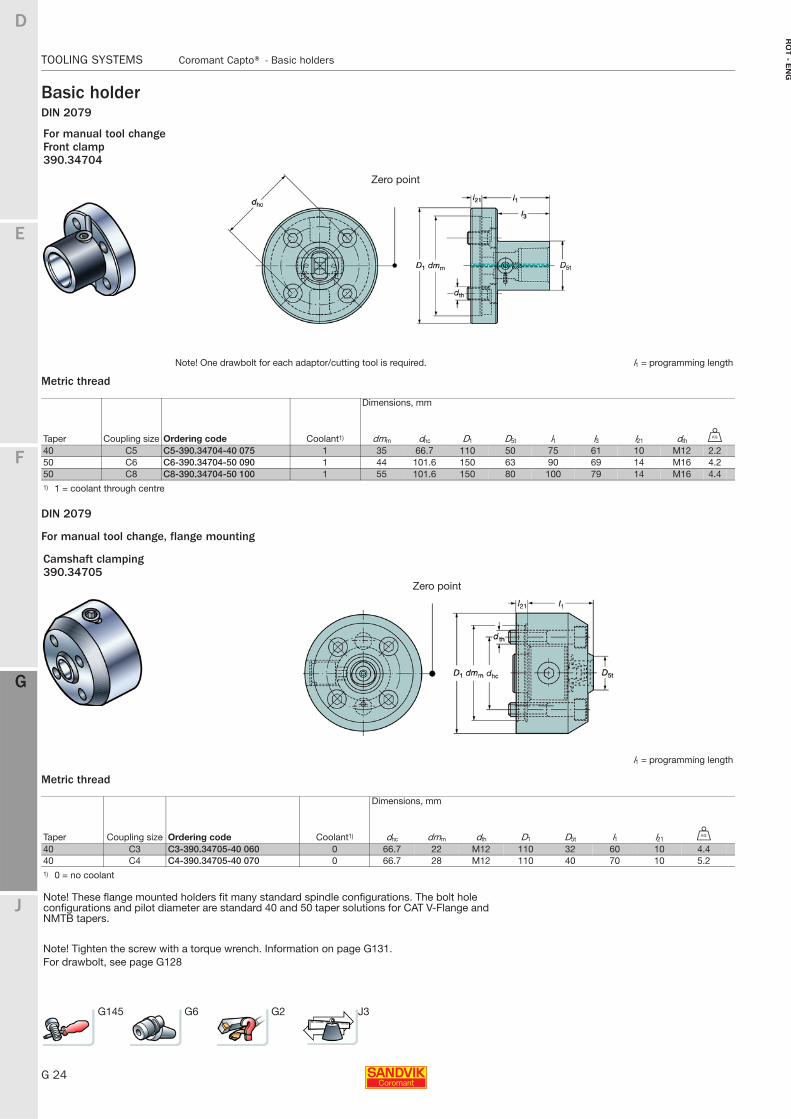
Basic holderDIN 2079
Metric thread
DIN 2079
For manual tool change, flange mounting
Metric thread
For manual tool changeFront clamp390.34704
Note! One drawbolt for each adaptor/cutting tool is required. l1 = programming length
Dimensions, mm
Taper Coupling size Ordering code Coolant1) dmm dhc D1 D5t l1 l3 l21 dth U
40 C5 C5-390.34704-40 075 1 35 66.7 110 50 75 61 10 M12 2.250 C6 C6-390.34704-50 090 1 44 101.6 150 63 90 69 14 M16 4.250 C8 C8-390.34704-50 100 1 55 101.6 150 80 100 79 14 M16 4.41) 1 = coolant through centre
Camshaft clamping390.34705
Zero point
l1 = programming length
Dimensions, mm
Taper Coupling size Ordering code Coolant1) dhc dmm dth D1 D5t l1 l21 U
40 C3 C3-390.34705-40 060 0 66.7 22 M12 110 32 60 10 4.440 C4 C4-390.34705-40 070 0 66.7 28 M12 110 40 70 10 5.21) 0 = no coolant
Note! These flange mounted holders fit many standard spindle configurations. The bolt hole configurations and pilot diameter are standard 40 and 50 taper solutions for CAT V-Flange and NMTB tapers.
Note! Tighten the screw with a torque wrench. Information on page G131.For drawbolt, see page G128
G145 G6 G2 J3
Zero point
E
G 25
F
G
J
D
G
Coromant Capto® - Basic holders TOOLING SYSTEMS
RO
T -
EN
G
TOOLING SYSTEMS Coromant Capto® − Basic holders
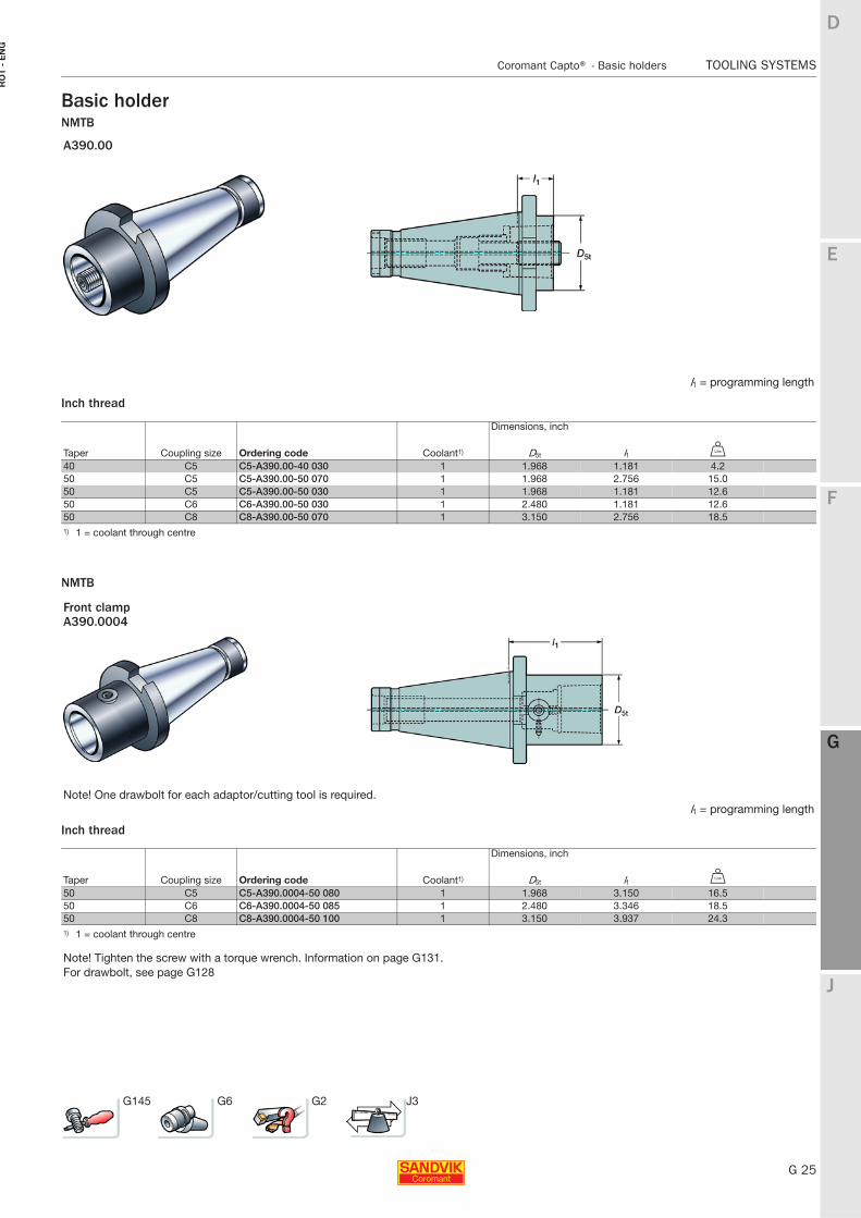
Basic holderNMTB
Inch thread
NMTB
Inch thread
A390.00
l1 = programming length
Dimensions, inch
Taper Coupling size Ordering code Coolant1) D5t l1 V
40 C5 C5-A390.00-40 030 1 1.968 1.181 4.250 C5 C5-A390.00-50 070 1 1.968 2.756 15.050 C5 C5-A390.00-50 030 1 1.968 1.181 12.650 C6 C6-A390.00-50 030 1 2.480 1.181 12.650 C8 C8-A390.00-50 070 1 3.150 2.756 18.51) 1 = coolant through centre
Front clampA390.0004
Note! One drawbolt for each adaptor/cutting tool is required.l1 = programming length
Dimensions, inch
Taper Coupling size Ordering code Coolant1) D5t l1 V
50 C5 C5-A390.0004-50 080 1 1.968 3.150 16.550 C6 C6-A390.0004-50 085 1 2.480 3.346 18.550 C8 C8-A390.0004-50 100 1 3.150 3.937 24.31) 1 = coolant through centre
Note! Tighten the screw with a torque wrench. Information on page G131.For drawbolt, see page G128
G145 G6 G2 J3
G 26
TOOLING SYSTEMS Coromant Capto® - Adaptors for rotating tools
E
F
G
J
D
G
RO
T - E
NG
TOOLING SYSTEMS Coromant Capto® − Adaptors for rotating tools
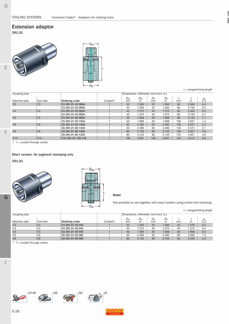
Extension adaptor391.01
Short version, for segment clamping only
391.01
l1 = programming length
Coupling size Dimensions, millimeter, inch (mm, in.)
Machine side Tool side Ordering code Coolant1)D5mmm
D5min.
D5tmm
D5tin.
l1mm
l1in. U
C3 C3 C3-391.01-32 060A 1 32 1.260 32 1.260 60 2.362 0.4C3-391.01-32 080A 1 32 1.260 32 1.260 80 3.150 0.5
C4 C4 C4-391.01-40 060A 1 40 1.575 40 1.575 60 2.362 0.5C4-391.01-40 080A 1 40 1.575 40 1.575 80 3.150 0.7
C5 C5 C5-391.01-50 080A 1 50 1.968 50 1.968 80 3.150 1.1C5-391.01-50 100A 1 50 1.968 50 1.968 100 3.937 1.4
C6 C6 C6-391.01-63 100A 1 63 2.480 63 2.480 100 3.937 2.2C6-391.01-63 140A 1 63 2.480 63 2.480 140 5.512 3.1
C8 C8 C8-391.01-80 100A 1 80 3.150 80 3.150 100 3.937 3.6C8-391.01-80 125A 1 80 3.150 80 3.150 125 4.921 4.6
C10 C10 C10-391.01-100 140 1 100 3.937 100 3.937 140 5.512 8.51) 1 = coolant through centre
Note!
Not possible to use together with basic holders using centre bolt clamping.
l1 = programming length
Coupling size Dimensions, millimeter, inch (mm, in.)
Machine side Tool side Ordering code Coolant1)D5mmm
D5min.
D5tmm
D5tin.
l1mm
l1in. U
C3 C3 C3-391.01-32 035 1 32 1.260 32 1.260 35 1.378 0.2C4 C4 C4-391.01-40 040 1 40 1.575 40 1.575 40 1.575 0.4C5 C5 C5-391.01-50 050 1 50 1.968 50 1.968 50 1.968 0.9C6 C6 C6-391.01-63 060 1 63 2.480 63 2.480 60 2.362 1.3C8 C8 C8-391.01-80 065 1 80 3.150 80 3.150 65 2.559 2.31) 1 = coolant through centre
G148 G6 G2 J3
E
G 27
F
G
J
D
G
Coromant Capto® - Adaptors for rotating tools TOOLING SYSTEMS
RO
T -
EN
G
TOOLING SYSTEMS Coromant Capto® − Adaptors for rotating tools
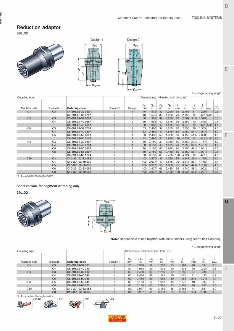
Reduction adaptor391.02
Short version, for segment clamping only
391.02
Design 1 Design 2
l1 = programming length
Coupling size Dimensions, millimeter, inch (mm, in.)
Machine side Tool side Ordering code Coolant1) DesignD5mmm
D5min.
D5tmm
D5tin.
l1mm
l1in.
l3mm
l3in. α21 U
C4 C3 C4-391.02-32 055A 1 1 40 1.575 32 1.260 55 2.165 31 1.220 0.5C4-391.02-32 070A 1 2 40 1.575 32 1.260 70 2.756 12 .472 6.0° 0.6
C5 C3 C5-391.02-32 060A 1 1 50 1.968 32 1.260 60 2.362 34.8 1.370 0.6C4 C5-391.02-40 065A 1 1 50 1.968 40 1.575 65 2.559 40 1.575 0.8
C5-391.02-40 085A 1 2 50 1.968 40 1.575 85 3.346 12 .472 5.4° 1.1C6 C3 C6-391.02-32 070A 1 1 63 2.480 32 1.260 70 2.756 39 1.535 1.1
C4 C6-391.02-40 080A 1 1 63 2.480 40 1.575 80 3.150 51.4 2.024 1.2C5 C6-391.02-50 080A 1 1 63 2.480 50 1.968 80 3.150 51.5 2.028 1.5
C6-391.02-50 110A 1 2 63 2.480 50 1.968 110 4.331 12 .472 4.9° 2.2C8 C3 C8-391.02-32 060A 1 1 80 3.150 32 1.260 60 2.362 29.3 1.154 1.7
C4 C8-391.02-40 070A 1 1 80 3.150 40 1.575 70 2.756 36.5 1.437 1.9C5 C8-391.02-50 080A 1 1 80 3.150 50 1.968 80 3.150 49.3 1.941 2.2C6 C8-391.02-63 080A 1 1 80 3.150 63 2.480 80 3.150 53.1 2.091 2.5
C8-391.02-63 120A 1 2 80 3.150 63 2.480 120 4.724 12 .472 4.0C10 C3 C10-391.02-32 085 1 1 100 3.937 32 1.260 85 3.346 29.4 1.158 4.0
C4 C10-391.02-40 090 1 1 100 3.937 40 1.575 90 3.543 36.7 1.445 4.1C5 C10-391.02-50 095 1 1 100 3.937 50 1.968 95 3.740 44.6 1.756 4.3C6 C10-391.02-63 095 1 1 100 3.937 63 2.480 95 3.740 48.3 1.902 4.5C8 C10-391.02-80 100 1 1 100 3.937 80 3.150 100 3.937 58.2 2.291 5.1
1) 1 = coolant through centre
Note! Not possible to use together with basic holders using centre bolt clamping.
l1 = programming length
Coupling size Dimensions, millimeter, inch (mm, in.)
Machine side Tool side Ordering code Coolant1)D5mmm
D5min.
D5tmm
D5tin.
l1mm
l1in.
l3mm
l3in. U
C5 C3 C5-391.02-32 033 1 50 1.968 32 1.260 33 1.299 10 .394 0.5C4 C5-391.02-40 040 1 50 1.968 40 1.575 40 1.575 18 .709 0.6
C6 C3 C6-391.02-32 032 1 63 2.480 32 1.260 32 1.260 6 .236 0.8C4 C6-391.02-40 040 1 63 2.480 40 1.575 40 1.575 11 .433 0.9C5 C6-391.02-50 050 1 63 2.480 50 1.968 50 1.968 26.5 1.043 1.0
C8 C5 C8-391.02-50 045 1 80 3.150 50 1.968 45 1.772 10 .394 1.8C6 C8-391.02-63 055 1 80 3.150 63 2.480 55 2.165 20 .787 2.0
C10 C6 C10-391.02-63 055 1 100 3.937 63 2.480 55 2.165 14 .551 3.2C8 C10-391.02-80 065 1 100 3.937 80 3.150 65 2.559 25.4 1.000 3.5
1) 1 = coolant through centreG148 G6 G2 J3
G 28
TOOLING SYSTEMS Coromant Capto® - Adaptors for rotating tools
E
F
G
J
D
G
RO
T - E
NG
TOOLING SYSTEMS Coromant Capto® − Adaptors for rotating tools
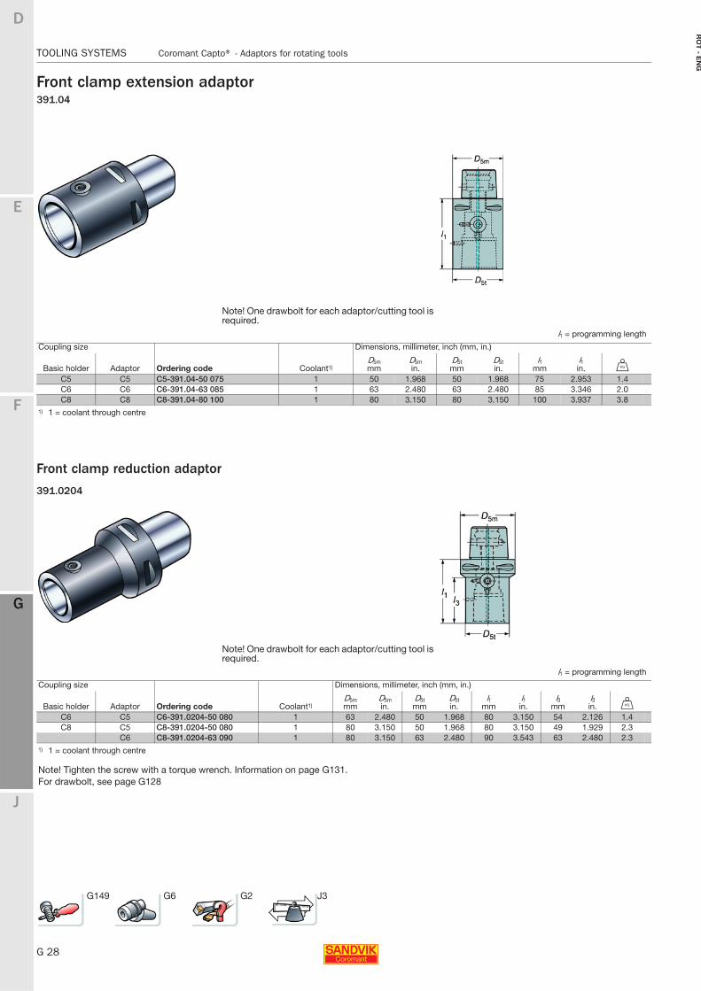
Front clamp extension adaptor391.04
Front clamp reduction adaptor
391.0204
Note! One drawbolt for each adaptor/cutting tool is required.
l1 = programming length
Coupling size Dimensions, millimeter, inch (mm, in.)
Basic holder Adaptor Ordering code Coolant1)D5mmm
D5min.
D5tmm
D5tin.
l1mm
l1in. U
C5 C5 C5-391.04-50 075 1 50 1.968 50 1.968 75 2.953 1.4C6 C6 C6-391.04-63 085 1 63 2.480 63 2.480 85 3.346 2.0C8 C8 C8-391.04-80 100 1 80 3.150 80 3.150 100 3.937 3.8
1) 1 = coolant through centre
Note! One drawbolt for each adaptor/cutting tool is required.
l1 = programming length
Coupling size Dimensions, millimeter, inch (mm, in.)
Basic holder Adaptor Ordering code Coolant1)D5mmm
D5min.
D5tmm
D5tin.
l1mm
l1in.
l3mm
l3in. U
C6 C5 C6-391.0204-50 080 1 63 2.480 50 1.968 80 3.150 54 2.126 1.4C8 C5 C8-391.0204-50 080 1 80 3.150 50 1.968 80 3.150 49 1.929 2.3
C6 C8-391.0204-63 090 1 80 3.150 63 2.480 90 3.543 63 2.480 2.31) 1 = coolant through centre
Note! Tighten the screw with a torque wrench. Information on page G131.For drawbolt, see page G128
G149 G6 G2 J3
E
G 29
F
G
J
D
G
Coromant Capto® - Adaptors for rotating tools TOOLING SYSTEMS
RO
T -
EN
G
TOOLING SYSTEMS Coromant Capto® − Adaptors for rotating tools
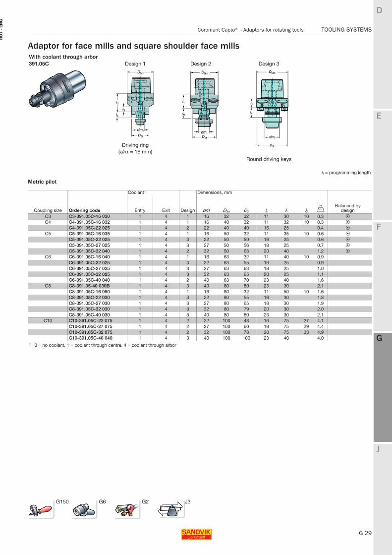
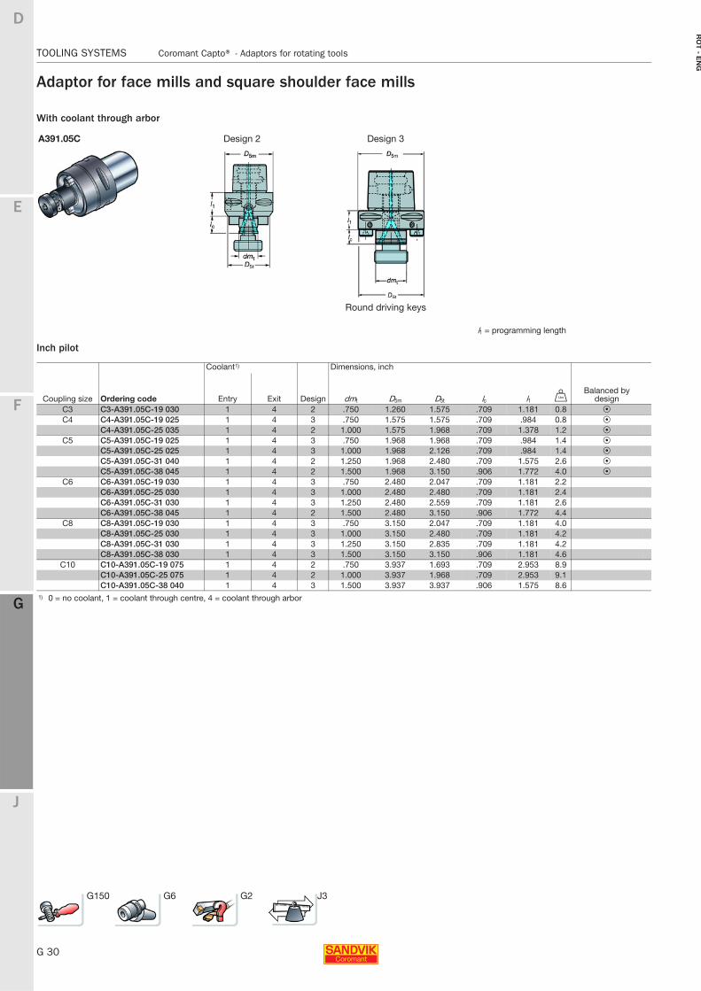
Adaptor for face mills and square shoulder face mills
Metric pilot
With coolant through arbor391.05C Design 1 Design 2 Design 3
Driving ring(dmt = 16 mm)
Round driving keys
l1 = programming length
Coolant1) Dimensions, mm
Coupling size Ordering code Entry Exit Design dmt D5m D5t lc l1 l3 UBalanced by
designC3 C3-391.05C-16 030 1 4 1 16 32 32 11 30 10 0.3 PC4 C4-391.05C-16 032 1 4 1 16 40 32 11 32 10 0.3 P
C4-391.05C-22 025 1 4 2 22 40 40 16 25 0.4 PC5 C5-391.05C-16 035 1 4 1 16 50 32 11 35 10 0.6 P
C5-391.05C-22 025 1 4 3 22 50 50 16 25 0.6 PC5-391.05C-27 025 1 4 3 27 50 56 18 25 0.7 PC5-391.05C-32 040 1 4 2 32 50 63 20 40 1.2 P
C6 C6-391.05C-16 040 1 4 1 16 63 32 11 40 10 0.9C6-391.05C-22 025 1 4 3 22 63 55 16 25 0.9C6-391.05C-27 025 1 4 3 27 63 63 18 25 1.0C6-391.05C-32 025 1 4 3 32 63 65 20 25 1.1C6-391.05C-40 040 1 4 2 40 63 70 23 40 1.6
C8 C8-391.05-40 030B 1 4 3 40 80 80 23 30 2.1C8-391.05C-16 050 1 4 1 16 80 32 11 50 10 1.6C8-391.05C-22 030 1 4 3 22 80 55 16 30 1.8C8-391.05C-27 030 1 4 3 27 80 65 18 30 1.9C8-391.05C-32 030 1 4 3 32 80 79 20 30 2.0C8-391.05C-40 030 1 4 3 40 80 80 23 30 2.1
C10 C10-391.05C-22 075 1 4 2 22 100 48 16 75 27 4.1C10-391.05C-27 075 1 4 2 27 100 60 18 75 29 4.4C10-391.05C-32 075 1 4 2 32 100 78 20 75 33 4.9C10-391.05C-40 040 1 4 3 40 100 100 23 40 4.0
1) 0 = no coolant, 1 = coolant through centre, 4 = coolant through arbor
G150 G6 G2 J3
G 30
TOOLING SYSTEMS Coromant Capto® - Adaptors for rotating tools
E
F
G
J
D
G
RO
T - E
NG
TOOLING SYSTEMS Coromant Capto® − Adaptors for rotating tools
Adaptor for face mills and square shoulder face mills
With coolant through arbor
Inch pilot
A391.05C Design 2 Design 3
Round driving keys
l1 = programming length
Coolant1) Dimensions, inch
Coupling size Ordering code Entry Exit Design dmt D5m D5t lc l1 VBalanced by
designC3 C3-A391.05C-19 030 1 4 2 .750 1.260 1.575 .709 1.181 0.8 PC4 C4-A391.05C-19 025 1 4 3 .750 1.575 1.575 .709 .984 0.8 P
C4-A391.05C-25 035 1 4 2 1.000 1.575 1.968 .709 1.378 1.2 PC5 C5-A391.05C-19 025 1 4 3 .750 1.968 1.968 .709 .984 1.4 P
C5-A391.05C-25 025 1 4 3 1.000 1.968 2.126 .709 .984 1.4 PC5-A391.05C-31 040 1 4 2 1.250 1.968 2.480 .709 1.575 2.6 PC5-A391.05C-38 045 1 4 2 1.500 1.968 3.150 .906 1.772 4.0 P
C6 C6-A391.05C-19 030 1 4 3 .750 2.480 2.047 .709 1.181 2.2C6-A391.05C-25 030 1 4 3 1.000 2.480 2.480 .709 1.181 2.4C6-A391.05C-31 030 1 4 3 1.250 2.480 2.559 .709 1.181 2.6C6-A391.05C-38 045 1 4 2 1.500 2.480 3.150 .906 1.772 4.4
C8 C8-A391.05C-19 030 1 4 3 .750 3.150 2.047 .709 1.181 4.0C8-A391.05C-25 030 1 4 3 1.000 3.150 2.480 .709 1.181 4.2C8-A391.05C-31 030 1 4 3 1.250 3.150 2.835 .709 1.181 4.2C8-A391.05C-38 030 1 4 3 1.500 3.150 3.150 .906 1.181 4.6
C10 C10-A391.05C-19 075 1 4 2 .750 3.937 1.693 .709 2.953 8.9C10-A391.05C-25 075 1 4 2 1.000 3.937 1.968 .709 2.953 9.1C10-A391.05C-38 040 1 4 3 1.500 3.937 3.937 .906 1.575 8.6
1) 0 = no coolant, 1 = coolant through centre, 4 = coolant through arbor
G150 G6 G2 J3
E
G 31
F
G
J
D
G
Coromant Capto® - Adaptors for rotating tools TOOLING SYSTEMS
RO
T -
EN
G
TOOLING SYSTEMS Coromant Capto® − Adaptors for rotating tools
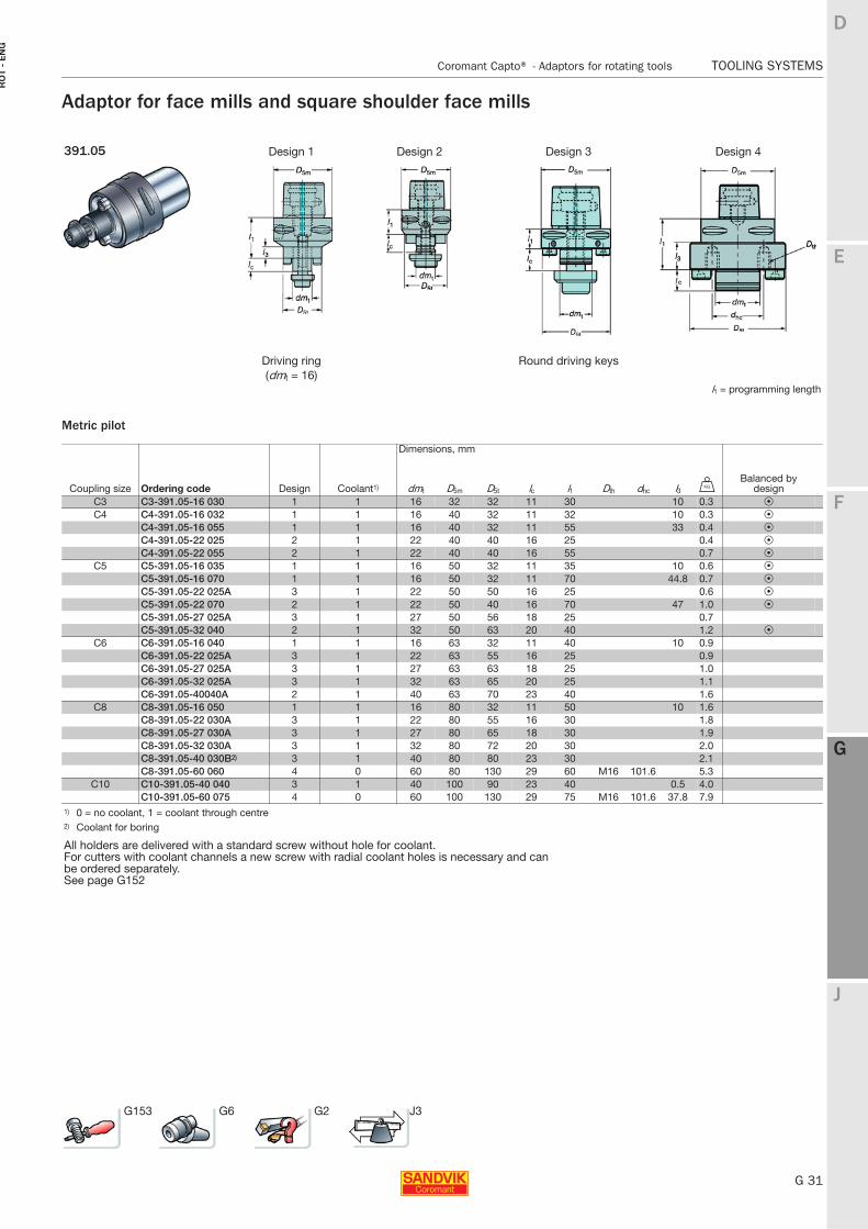
Adaptor for face mills and square shoulder face mills
Metric pilot
391.05 Design 1 Design 2 Design 3 Design 4
Driving ring Round driving keys(dmt = 16)
l1 = programming length
Dimensions, mm
Coupling size Ordering code Design Coolant1) dmt D5m D5t lc l1 Dth dhc l3 UBalanced by
designC3 C3-391.05-16 030 1 1 16 32 32 11 30 10 0.3 PC4 C4-391.05-16 032 1 1 16 40 32 11 32 10 0.3 P
C4-391.05-16 055 1 1 16 40 32 11 55 33 0.4 PC4-391.05-22 025 2 1 22 40 40 16 25 0.4 PC4-391.05-22 055 2 1 22 40 40 16 55 0.7 P
C5 C5-391.05-16 035 1 1 16 50 32 11 35 10 0.6 PC5-391.05-16 070 1 1 16 50 32 11 70 44.8 0.7 PC5-391.05-22 025A 3 1 22 50 50 16 25 0.6 PC5-391.05-22 070 2 1 22 50 40 16 70 47 1.0 PC5-391.05-27 025A 3 1 27 50 56 18 25 0.7C5-391.05-32 040 2 1 32 50 63 20 40 1.2 P
C6 C6-391.05-16 040 1 1 16 63 32 11 40 10 0.9C6-391.05-22 025A 3 1 22 63 55 16 25 0.9C6-391.05-27 025A 3 1 27 63 63 18 25 1.0C6-391.05-32 025A 3 1 32 63 65 20 25 1.1C6-391.05-40040A 2 1 40 63 70 23 40 1.6
C8 C8-391.05-16 050 1 1 16 80 32 11 50 10 1.6C8-391.05-22 030A 3 1 22 80 55 16 30 1.8C8-391.05-27 030A 3 1 27 80 65 18 30 1.9C8-391.05-32 030A 3 1 32 80 72 20 30 2.0C8-391.05-40 030B2) 3 1 40 80 80 23 30 2.1C8-391.05-60 060 4 0 60 80 130 29 60 M16 101.6 5.3
C10 C10-391.05-40 040 3 1 40 100 90 23 40 0.5 4.0C10-391.05-60 075 4 0 60 100 130 29 75 M16 101.6 37.8 7.9
1) 0 = no coolant, 1 = coolant through centre2) Coolant for boring
All holders are delivered with a standard screw without hole for coolant.For cutters with coolant channels a new screw with radial coolant holes is necessary and can be ordered separately.See page G152
G153 G6 G2 J3
G 32
TOOLING SYSTEMS Coromant Capto® - Adaptors for rotating tools
E
F
G
J
D
G
RO
T - E
NG
TOOLING SYSTEMS Coromant Capto® − Adaptors for rotating tools
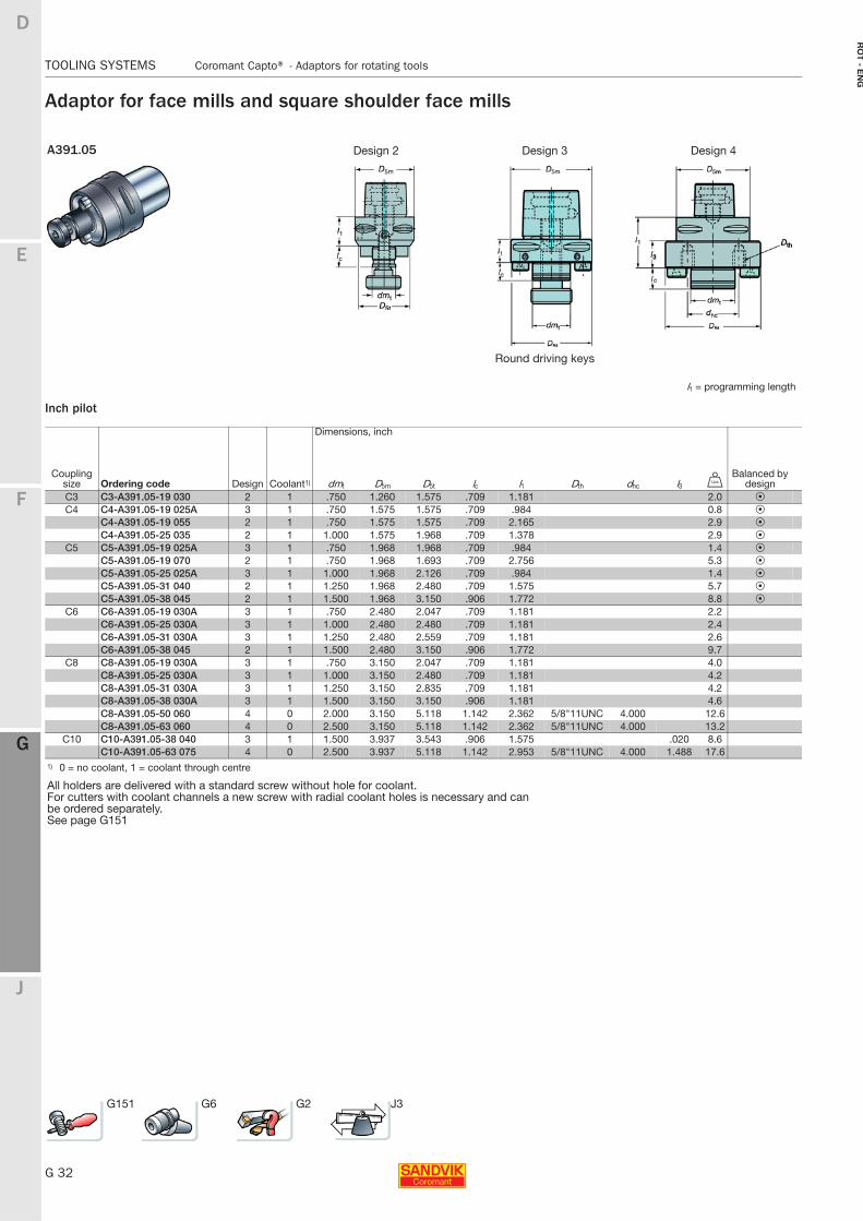
Adaptor for face mills and square shoulder face mills
Inch pilot
A391.05 Design 2 Design 3 Design 4
Round driving keys
l1 = programming length
Dimensions, inch
Coupling size Ordering code Design Coolant1) dmt D5m D5t lc l1 Dth dhc l3 V
Balanced by design
C3 C3-A391.05-19 030 2 1 .750 1.260 1.575 .709 1.181 2.0 PC4 C4-A391.05-19 025A 3 1 .750 1.575 1.575 .709 .984 0.8 P
C4-A391.05-19 055 2 1 .750 1.575 1.575 .709 2.165 2.9 PC4-A391.05-25 035 2 1 1.000 1.575 1.968 .709 1.378 2.9 P
C5 C5-A391.05-19 025A 3 1 .750 1.968 1.968 .709 .984 1.4 PC5-A391.05-19 070 2 1 .750 1.968 1.693 .709 2.756 5.3 PC5-A391.05-25 025A 3 1 1.000 1.968 2.126 .709 .984 1.4 PC5-A391.05-31 040 2 1 1.250 1.968 2.480 .709 1.575 5.7 PC5-A391.05-38 045 2 1 1.500 1.968 3.150 .906 1.772 8.8 P
C6 C6-A391.05-19 030A 3 1 .750 2.480 2.047 .709 1.181 2.2C6-A391.05-25 030A 3 1 1.000 2.480 2.480 .709 1.181 2.4C6-A391.05-31 030A 3 1 1.250 2.480 2.559 .709 1.181 2.6C6-A391.05-38 045 2 1 1.500 2.480 3.150 .906 1.772 9.7
C8 C8-A391.05-19 030A 3 1 .750 3.150 2.047 .709 1.181 4.0C8-A391.05-25 030A 3 1 1.000 3.150 2.480 .709 1.181 4.2C8-A391.05-31 030A 3 1 1.250 3.150 2.835 .709 1.181 4.2C8-A391.05-38 030A 3 1 1.500 3.150 3.150 .906 1.181 4.6C8-A391.05-50 060 4 0 2.000 3.150 5.118 1.142 2.362 5/8"11UNC 4.000 12.6C8-A391.05-63 060 4 0 2.500 3.150 5.118 1.142 2.362 5/8"11UNC 4.000 13.2
C10 C10-A391.05-38 040 3 1 1.500 3.937 3.543 .906 1.575 .020 8.6C10-A391.05-63 075 4 0 2.500 3.937 5.118 1.142 2.953 5/8"11UNC 4.000 1.488 17.6
1) 0 = no coolant, 1 = coolant through centre
All holders are delivered with a standard screw without hole for coolant.For cutters with coolant channels a new screw with radial coolant holes is necessary and can be ordered separately.See page G151
G151 G6 G2 J3
E
G 33
F
G
J
D
G
Coromant Capto® - Adaptors for rotating tools TOOLING SYSTEMS
RO
T -
EN
G
TOOLING SYSTEMS Coromant Capto® − Adaptors for rotating tools
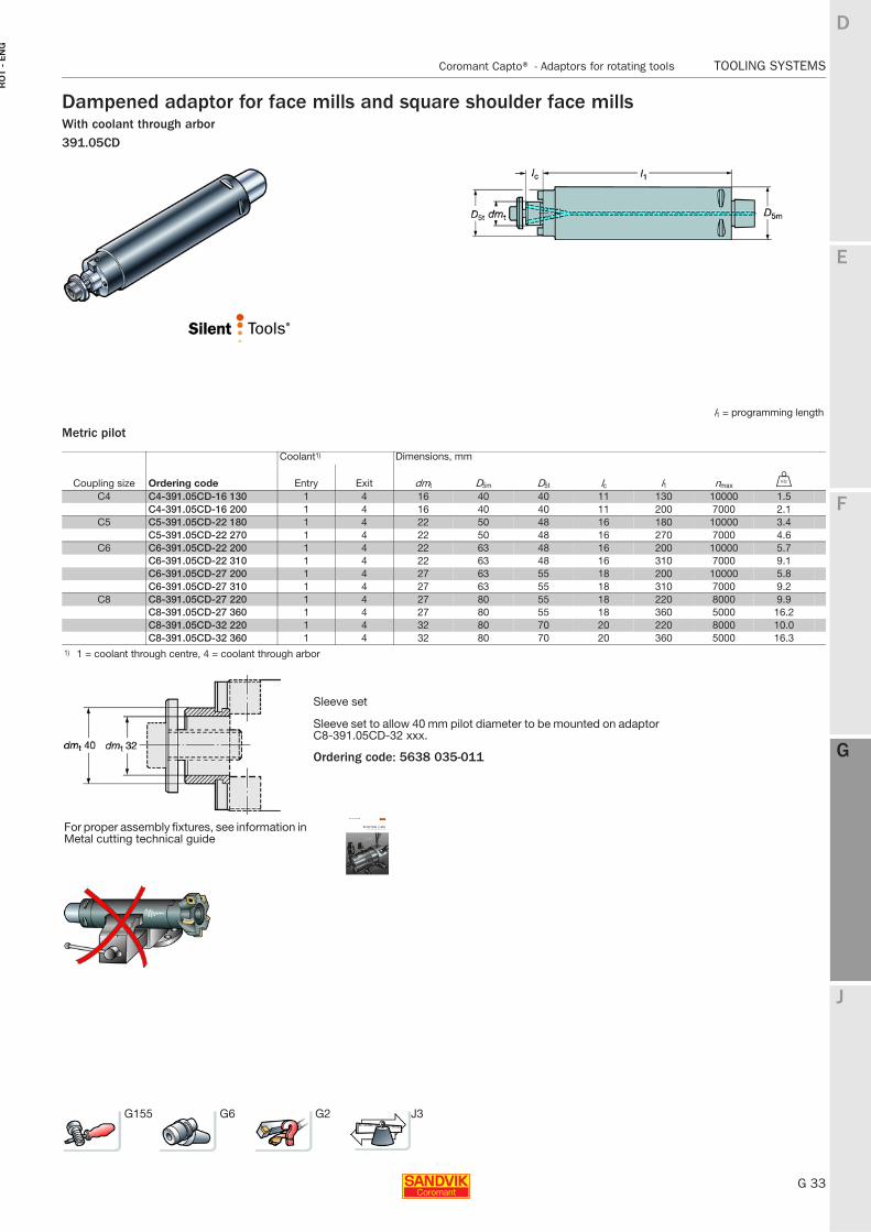
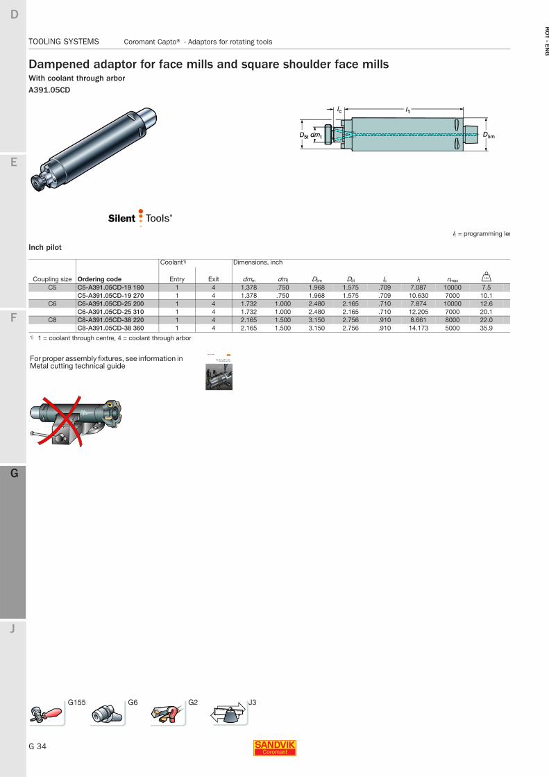
Dampened adaptor for face mills and square shoulder face millsWith coolant through arbor391.05CD
Metric pilot
l1 = programming length
Coolant1) Dimensions, mm
Coupling size Ordering code Entry Exit dmt D5m D5t lc l1 nmax U
C4 C4-391.05CD-16 130 1 4 16 40 40 11 130 10000 1.5C4-391.05CD-16 200 1 4 16 40 40 11 200 7000 2.1
C5 C5-391.05CD-22 180 1 4 22 50 48 16 180 10000 3.4C5-391.05CD-22 270 1 4 22 50 48 16 270 7000 4.6
C6 C6-391.05CD-22 200 1 4 22 63 48 16 200 10000 5.7C6-391.05CD-22 310 1 4 22 63 48 16 310 7000 9.1C6-391.05CD-27 200 1 4 27 63 55 18 200 10000 5.8C6-391.05CD-27 310 1 4 27 63 55 18 310 7000 9.2
C8 C8-391.05CD-27 220 1 4 27 80 55 18 220 8000 9.9C8-391.05CD-27 360 1 4 27 80 55 18 360 5000 16.2C8-391.05CD-32 220 1 4 32 80 70 20 220 8000 10.0C8-391.05CD-32 360 1 4 32 80 70 20 360 5000 16.3
1) 1 = coolant through centre, 4 = coolant through arbor
Sleeve set
Sleeve set to allow 40 mm pilot diameter to be mounted on adaptor C8-391.05CD-32 xxx.
Ordering code: 5638 035-011
For proper assembly fixtures, see information in Metal cutting technical guide
G155 G6 G2 J3
G 34
TOOLING SYSTEMS Coromant Capto® - Adaptors for rotating tools
E
F
G
J
D
G
RO
T - E
NG
TOOLING SYSTEMS Coromant Capto® − Adaptors for rotating tools
Dampened adaptor for face mills and square shoulder face millsWith coolant through arborA391.05CD
Inch pilot
l1 = programming len
Coolant1) Dimensions, inch
Coupling size Ordering code Entry Exit dmm dmt D5m D5t lc l1 nmax V
C5 C5-A391.05CD-19 180 1 4 1.378 .750 1.968 1.575 .709 7.087 10000 7.5C5-A391.05CD-19 270 1 4 1.378 .750 1.968 1.575 .709 10.630 7000 10.1
C6 C6-A391.05CD-25 200 1 4 1.732 1.000 2.480 2.165 .710 7.874 10000 12.6C6-A391.05CD-25 310 1 4 1.732 1.000 2.480 2.165 .710 12.205 7000 20.1
C8 C8-A391.05CD-38 220 1 4 2.165 1.500 3.150 2.756 .910 8.661 8000 22.0C8-A391.05CD-38 360 1 4 2.165 1.500 3.150 2.756 .910 14.173 5000 35.9
1) 1 = coolant through centre, 4 = coolant through arbor
For proper assembly fixtures, see information in Metal cutting technical guide
G155 G6 G2 J3
E
G 35
F
G
J
D
G
Coromant Capto® - Adaptors for rotating tools TOOLING SYSTEMS
RO
T -
EN
G
TOOLING SYSTEMS Coromant Capto® − Adaptors for rotating tools
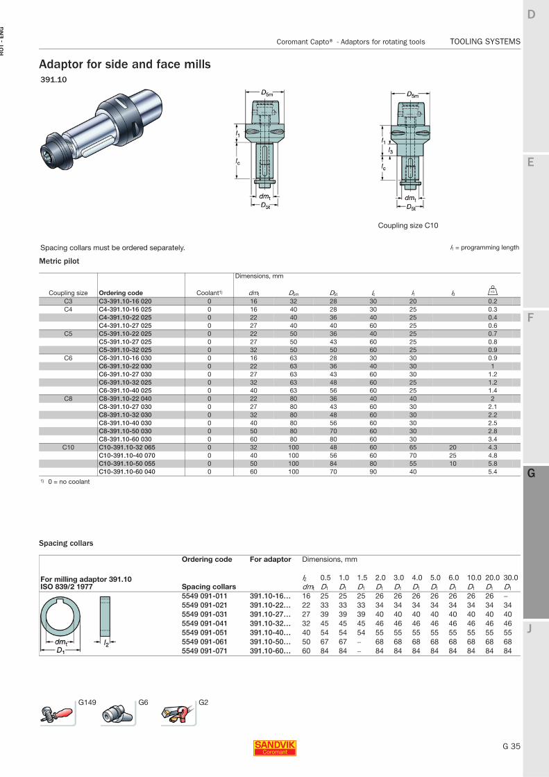
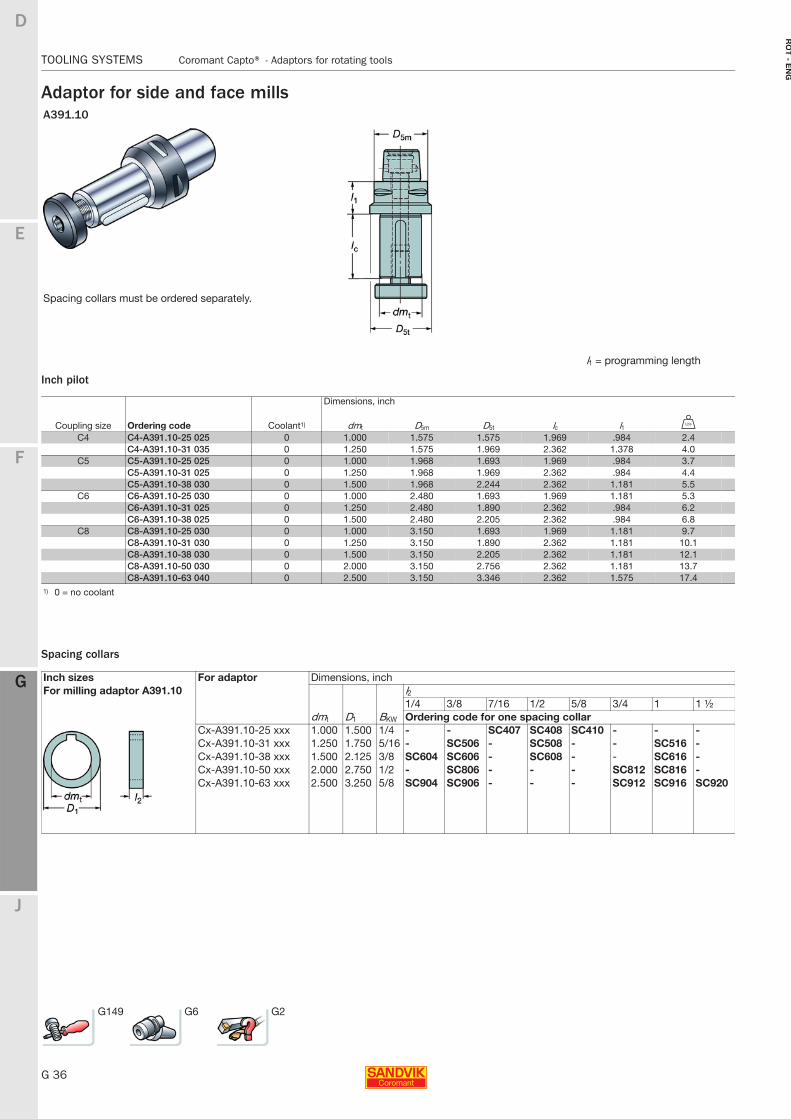
Adaptor for side and face mills
Metric pilot
Spacing collars
391.10
Coupling size C10
Spacing collars must be ordered separately. l1 = programming length
Dimensions, mm
Coupling size Ordering code Coolant1) dmt D5m D5t lc l1 l3 U
C3 C3-391.10-16 020 0 16 32 28 30 20 0.2C4 C4-391.10-16 025 0 16 40 28 30 25 0.3
C4-391.10-22 025 0 22 40 36 40 25 0.4C4-391.10-27 025 0 27 40 40 60 25 0.6
C5 C5-391.10-22 025 0 22 50 36 40 25 0.7C5-391.10-27 025 0 27 50 43 60 25 0.8C5-391.10-32 025 0 32 50 50 60 25 0.9
C6 C6-391.10-16 030 0 16 63 28 30 30 0.9C6-391.10-22 030 0 22 63 36 40 30 1C6-391.10-27 030 0 27 63 43 60 30 1.2C6-391.10-32 025 0 32 63 48 60 25 1.2C6-391.10-40 025 0 40 63 56 60 25 1.4
C8 C8-391.10-22 040 0 22 80 36 40 40 2C8-391.10-27 030 0 27 80 43 60 30 2.1C8-391.10-32 030 0 32 80 48 60 30 2.2C8-391.10-40 030 0 40 80 56 60 30 2.5C8-391.10-50 030 0 50 80 70 60 30 2.8C8-391.10-60 030 0 60 80 80 60 30 3.4
C10 C10-391.10-32 065 0 32 100 48 60 65 20 4.3C10-391.10-40 070 0 40 100 56 60 70 25 4.8C10-391.10-50 055 0 50 100 84 80 55 10 5.8C10-391.10-60 040 0 60 100 70 90 40 5.4
1) 0 = no coolant
Ordering code For adaptor Dimensions, mm
For milling adaptor 391.10 ISO 839/2 1977 Spacing collars
l2 0.5 1.0 1.5 2.0 3.0 4.0 5.0 6.0 10.0 20.0 30.0dmt D1 D1 D1 D1 D1 D1 D1 D1 D1 D1 D1
5549 091-011 391.10-16… 16 25 25 25 26 26 26 26 26 26 26 −
5549 091-021 391.10-22… 22 33 33 33 34 34 34 34 34 34 34 345549 091-031 391.10-27… 27 39 39 39 40 40 40 40 40 40 40 405549 091-041 391.10-32… 32 45 45 45 46 46 46 46 46 46 46 465549 091-051 391.10-40… 40 54 54 54 55 55 55 55 55 55 55 555549 091-061 391.10-50… 50 67 67 − 68 68 68 68 68 68 68 685549 091-071 391.10-60… 60 84 84 − 84 84 84 84 84 84 84 84
G149 G6 G2
G 36
TOOLING SYSTEMS Coromant Capto® - Adaptors for rotating tools
E
F
G
J
D
G
RO
T - E
NG
TOOLING SYSTEMS Coromant Capto® − Adaptors for rotating tools
Adaptor for side and face mills
Inch pilot
Spacing collars
A391.10
Spacing collars must be ordered separately.
l1 = programming length
Dimensions, inch
Coupling size Ordering code Coolant1) dmt D5m D5t lc l1 V
C4 C4-A391.10-25 025 0 1.000 1.575 1.575 1.969 .984 2.4C4-A391.10-31 035 0 1.250 1.575 1.969 2.362 1.378 4.0
C5 C5-A391.10-25 025 0 1.000 1.968 1.693 1.969 .984 3.7C5-A391.10-31 025 0 1.250 1.968 1.969 2.362 .984 4.4C5-A391.10-38 030 0 1.500 1.968 2.244 2.362 1.181 5.5
C6 C6-A391.10-25 030 0 1.000 2.480 1.693 1.969 1.181 5.3C6-A391.10-31 025 0 1.250 2.480 1.890 2.362 .984 6.2C6-A391.10-38 025 0 1.500 2.480 2.205 2.362 .984 6.8
C8 C8-A391.10-25 030 0 1.000 3.150 1.693 1.969 1.181 9.7C8-A391.10-31 030 0 1.250 3.150 1.890 2.362 1.181 10.1C8-A391.10-38 030 0 1.500 3.150 2.205 2.362 1.181 12.1C8-A391.10-50 030 0 2.000 3.150 2.756 2.362 1.181 13.7C8-A391.10-63 040 0 2.500 3.150 3.346 2.362 1.575 17.4
1) 0 = no coolant
Inch sizes For adaptor Dimensions, inchFor milling adaptor A391.10
dmt D1
l21/4 3/8 7/16 1/2 5/8 3/4 1 1 ½
BKW Ordering code for one spacing collarCx-A391.10-25 xxx 1.000 1.500 1/4 - - SC407 SC408 SC410 - - -Cx-A391.10-31 xxx 1.250 1.750 5/16 - SC506 - SC508 - - SC516 -Cx-A391.10-38 xxx 1.500 2.125 3/8 SC604 SC606 - SC608 - - SC616 -Cx-A391.10-50 xxx 2.000 2.750 1/2 - SC806 - - - SC812 SC816 -Cx-A391.10-63 xxx 2.500 3.250 5/8 SC904 SC906 - - - SC912 SC916 SC920
G149 G6 G2
E
G 37
F
G
J
D
G
Coromant Capto® - Adaptors for rotating tools TOOLING SYSTEMS
RO
T -
EN
G
TOOLING SYSTEMS Coromant Capto® − Adaptors for rotating tools
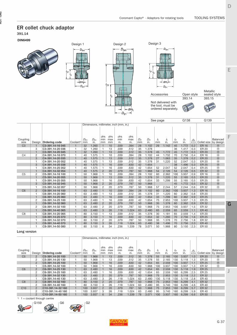
ER collet chuck adaptor391.14
Long version
DIN6499Design 1 Design 2
Accessories Open styleMetallic sealed style
393.14 393.15Not delivered with the tool, must be ordered separately.
See page G138 G139Dimensions, millimeter, inch (mm, in.)
Coupling size Design Ordering code Coolant1)
D5mmm
D5min.
dmtminmm
dmtmaxmm
dmtmin in.
dmtmaxin.
D21mm
D21in.
l3mm
l3in.
l21 mm
l21 in. U Collet size
Balanced by design
C3 1 C3-391.14-16 045 1 32 1.260 1 10 .039 .394 28 1.102 29 1.142 45 1.772 0.2 ER 16 P3 C3-391.14-20 036 1 32 1.260 1 13 .039 .512 35 1.378 36 1.417 0.3 ER 20 P1 C3-391.14-20 045 1 32 1.260 1 13 .039 .512 35 1.378 45 1.772 45 1.772 0.3 ER 20 P
C4 2 C4-391.14-16 070 1 40 1.575 1 10 .039 .394 28 1.102 44 1.732 70 2.756 0.4 ER 16 P3 C4-391.14-20 035 1 40 1.575 1 13 .039 .512 35 1.378 27 1.063 35 1.378 0.2 ER 20 P1 C4-391.14-20 052 1 40 1.575 1 13 .039 .512 35 1.378 31 1.220 52 2.047 0.3 ER 20 P3 C4-391.14-25 038 1 40 1.575 1 16 .039 .630 42 1.654 38 1.496 0.3 ER 25 P1 C4-391.14-25 052 1 40 1.575 1 16 .039 .630 42 1.654 52 2.047 52 2.047 0.4 ER 25 P1 C4-391.14-32 054 1 40 1.575 2 20 .079 .787 50 1.968 54 2.126 54 2.126 0.5 ER 32 P
C5 2 C5-391.14-16 100 1 50 1.968 1 10 .039 .394 28 1.102 60 2.362 100 3.937 0.9 ER 16 P1 C5-391.14-20 055 1 50 1.968 1 13 .039 .512 35 1.378 31 1.220 55 2.165 0.5 ER 20 P1 C5-391.14-25 055 1 50 1.968 1 16 .039 .630 42 1.654 33 1.299 55 2.165 0.5 ER 25 P3 C5-391.14-32 045 1 50 1.968 2 20 .079 .787 50 1.968 45 1.772 0.5 ER 32 P1 C5-391.14-32 057 1 50 1.968 2 20 .079 .787 50 1.968 57 2.244 57 2.244 0.6 ER 32 P
C6 2 C6-391.14-16 100 1 63 2.480 1 10 .039 .394 28 1.102 60 2.362 100 3.937 1.3 ER 161 C6-391.14-20 060 1 63 2.480 1 13 .039 .512 35 1.378 31 1.220 60 2.362 0.8 ER 201 C6-391.14-25 060 1 63 2.480 1 16 .039 .630 42 1.654 33 1.299 60 2.362 0.9 ER 252 C6-391.14-25 100 1 63 2.480 1 16 .039 .630 42 1.654 75 2.953 100 3.937 1.3 ER 251 C6-391.14-32 060 1 63 2.480 2 20 .079 .787 50 1.968 35 1.378 60 2.362 0.9 ER 322 C6-391.14-32 100 1 63 2.480 2 20 .079 .787 50 1.968 75 2.953 100 3.937 1.5 ER 321 C6-391.14-40 065 1 63 2.480 3 26 .118 1.024 63 2.480 65 2.559 65 2.559 1.1 ER 40
C8 1 C8-391.14-20 065 1 80 3.150 1 13 .039 .512 35 1.378 30 1.181 65 2.559 1.4 ER 201 C8-391.14-25 070 1 80 3.150 1 16 .039 .630 42 1.654 32 1.260 70 2.756 1.6 ER 251 C8-391.14-32 070 1 80 3.150 2 20 .079 .787 50 1.968 35 1.378 70 2.756 1.8 ER 321 C8-391.14-40 070 1 80 3.150 3 26 .118 1.024 63 2.480 38 1.496 70 2.756 2.0 ER 401 C8-391.14-50 080 1 80 3.150 6 34 .236 1.339 78 3.071 50 1.968 80 3.150 2.3 ER 50
Dimensions, millimeter, inch (mm, in.)
Coupling size Design Ordering code Coolant1)
D5mmm
D5min.
dmtminmm
dmtmaxmm
dmtmin in.
dmtmaxin.
D21mm
D21in.
l3mm
l3in.
l21 mm
l21 in. U Collet size
Balanced by design
C5 2 C5-391.14-20 100 1 50 1.968 1 13 .039 .512 35 1.378 55 2.165 100 3.937 1.0 ER 20 P2 C5-391.14-20 130 1 50 1.968 1 13 .039 .512 35 1.378 55 2.165 130 5.118 1.3 ER 20 P2 C5-391.14-25 100 1 50 1.968 1 16 .039 .630 42 1.654 65 2.559 100 3.937 1.1 ER 25 P1 C5-391.14-32 100 1 50 1.968 1 16 .039 .630 50 1.968 100 3.937 100 3.937 1.3 ER 32 P
C6 2 C6-391.14-25 130 1 63 2.480 1 16 .039 .630 42 1.654 65 2.559 130 5.118 1.9 ER 252 C6-391.14-25 160 1 63 2.480 1 16 .039 .630 42 1.654 65 2.559 160 6.299 2.5 ER 252 C6-391.14-32 130 1 63 2.480 2 20 .079 .787 50 1.968 75 2.953 130 5.118 2.2 ER 321 C6-391.14-40 130 1 63 2.480 3 26 .118 1.024 63 2.480 130 5.118 130 5.118 2.8 ER 40
C8 2 C8-391.14-32 160 1 80 3.150 2 20 .079 .787 50 1.968 75 2.953 160 6.299 4.1 ER 322 C8-391.14-40 160 1 80 3.150 3 26 .118 1.024 63 2.480 95 3.740 160 6.299 4.6 ER 40
C10 2 C10-391.14-32 160 1 100 3.937 2 20 .079 .787 50 1.968 75 2.953 160 6.299 5.7 ER 322 C10-391.14-40 160 1 100 3.937 3 26 .118 1.024 63 2.480 95 3.740 160 6.299 5.9 ER 402 C10-391.14-50 160 1 100 3.937 6 34 .236 1.339 78 3.071 100 3.937 160 6.299 6.6 ER 50
1) 1 = coolant through centre
G159 G6 G2
Design 3
G 38
TOOLING SYSTEMS Coromant Capto® - Adaptors for rotating tools
E
F
G
J
D
G
RO
T - E
NG
TOOLING SYSTEMS Coromant Capto® − Adaptors for rotating tools
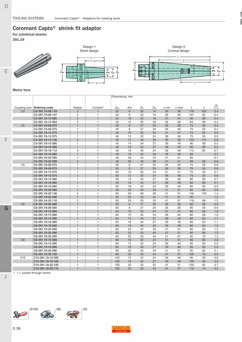
Coromant Capto® shrink fit adaptorFor cylindrical shanks391.19
Metric bore
Design 1 Design 2Short design Conical design
Dimensions, mm
Coupling size Ordering code Design Coolant1) D5m dmt D21 D22 lc min lc max l1 l3 U
C3 C3-391.19-06 118 2 1 32 6 32 14 26 36 118 103 0.4C3-391.19-08 107 2 1 32 8 32 16 26 36 107 92 0.4C3-391.19-10 095 2 1 32 10 32 18 31 41 95 80 0.4C3-391.19-12 084 2 1 32 12 32 20 36 46 84 69 0.4
C4 C4-391.19-06 075 1 1 40 6 27 20 26 36 75 55 0.4C4-391.19-08 075 1 1 40 8 27 20 26 36 75 55 0.4C4-391.19-10 075 1 1 40 10 32 24 31 41 75 55 0.5C4-391.19-12 075 1 1 40 12 32 24 36 46 75 55 0.5C4-391.19-12 135 2 1 40 12 40 20 36 46 135 115 0.8C4-391.19-14 080 1 1 40 14 34 27 36 46 80 60 0.5C4-391.19-16 080 1 1 40 16 34 27 39 49 80 60 0.5C4-391.19-16 112 2 1 40 16 40 24 39 49 112 92 0.7C4-391.19-18 080 1 1 40 18 42 33 39 49 80 0.7C4-391.19-20 085 1 1 40 20 42 33 41 51 85 0.7C4-391.19-20 089 2 1 40 20 40 28 41 51 89 69 0.6
C5 C5-391.19-06 075 1 1 50 6 27 20 26 36 75 55 0.6C5-391.19-08 075 1 1 50 8 27 20 26 36 75 55 0.6C5-391.19-10 075 1 1 50 10 32 24 31 41 75 55 0.7C5-391.19-12 075 1 1 50 12 32 24 36 46 75 55 0.6C5-391.19-14 080 1 1 50 14 34 27 36 46 80 60 0.7C5-391.19-16 080 1 1 50 16 34 27 39 49 80 60 0.7C5-391.19-18 080 1 1 50 18 42 33 39 49 80 60 0.9C5-391.19-20 085 1 1 50 20 42 33 41 51 85 65 0.9C5-391.19-20 146 2 1 50 20 50 28 41 51 146 126 1.4C5-391.19-25 090 1 1 50 25 53 44 47 57 90 1.2C5-391.19-25 118 2 1 50 25 50 33 47 57 118 98 1.2
C6 C6-391.19-06 080 1 1 63 6 27 20 26 36 80 58 0.9C6-391.19-08 080 1 1 63 8 27 20 26 36 80 58 0.9C6-391.19-10 080 1 1 63 10 32 24 31 41 80 58 1.0C6-391.19-12 080 1 1 63 12 32 24 36 46 80 58 1.0C6-391.19-14 085 1 1 63 14 34 27 36 46 85 63 1.1C6-391.19-16 085 1 1 63 16 34 27 39 49 85 63 1.1C6-391.19-18 085 1 1 63 18 42 33 39 49 85 63 1.3C6-391.19-20 085 1 1 63 20 42 33 41 51 85 63 1.2C6-391.19-25 090 1 1 63 25 53 44 47 57 90 68 1.5C6-391.19-32 095 1 1 63 32 53 44 51 61 95 73 1.3
C8 C8-391.19-10 090 1 1 80 10 32 24 31 41 90 60 2.0C8-391.19-12 090 1 1 80 12 32 24 36 46 90 60 2.0C8-391.19-16 095 1 1 80 16 34 27 39 49 95 65 2.0C8-391.19-20 095 1 1 80 20 42 33 41 51 95 65 2.1C8-391.19-25 100 1 1 80 25 53 44 47 57 100 70 2.5
C10 C10-391.19-12 095 1 1 100 12 32 24 36 46 95 59 3.6C10-391.19-16 100 1 1 100 16 34 27 39 49 100 64 3.6C10-391.19-20 100 1 1 100 20 42 33 41 51 100 64 3.7C10-391.19-25 110 1 1 100 25 53 44 47 57 110 74 4.2
1) 1 = coolant through centre
G159 G6 G2
E
G 39
F
G
J
D
G
Coromant Capto® - Adaptors for rotating tools TOOLING SYSTEMS
RO
T -
EN
G
TOOLING SYSTEMS Coromant Capto® − Adaptors for rotating tools
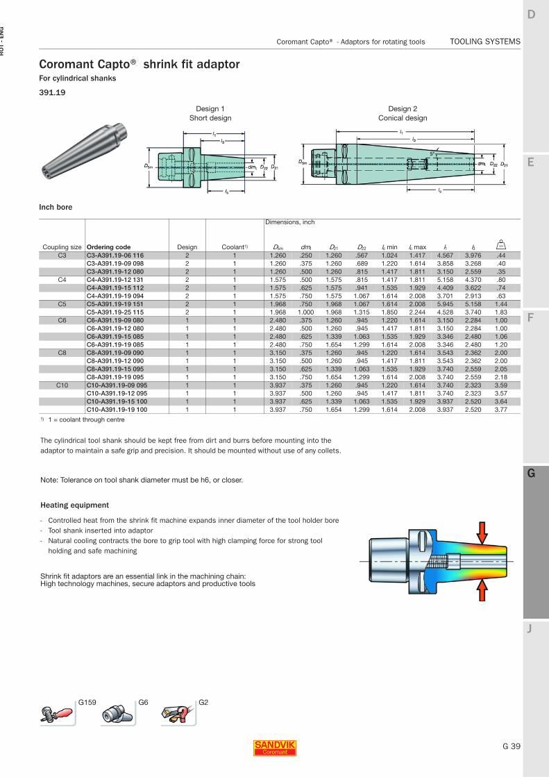
Coromant Capto® shrink fit adaptorFor cylindrical shanks
391.19
Inch bore
Design 1 Design 2Short design Conical design
Dimensions, inch
Coupling size Ordering code Design Coolant1) D5m dmt D21 D22 lc min lc max l1 l3 V
C3 C3-A391.19-06 116 2 1 1.260 .250 1.260 .567 1.024 1.417 4.567 3.976 .44C3-A391.19-09 098 2 1 1.260 .375 1.260 .689 1.220 1.614 3.858 3.268 .40C3-A391.19-12 080 2 1 1.260 .500 1.260 .815 1.417 1.811 3.150 2.559 .35
C4 C4-A391.19-12 131 2 1 1.575 .500 1.575 .815 1.417 1.811 5.158 4.370 .80C4-A391.19-15 112 2 1 1.575 .625 1.575 .941 1.535 1.929 4.409 3.622 .74C4-A391.19-19 094 2 1 1.575 .750 1.575 1.067 1.614 2.008 3.701 2.913 .63
C5 C5-A391.19-19 151 2 1 1.968 .750 1.968 1.067 1.614 2.008 5.945 5.158 1.44C5-A391.19-25 115 2 1 1.968 1.000 1.968 1.315 1.850 2.244 4.528 3.740 1.83
C6 C6-A391.19-09 080 1 1 2.480 .375 1.260 .945 1.220 1.614 3.150 2.284 1.00C6-A391.19-12 080 1 1 2.480 .500 1.260 .945 1.417 1.811 3.150 2.284 1.00C6-A391.19-15 085 1 1 2.480 .625 1.339 1.063 1.535 1.929 3.346 2.480 1.06C6-A391.19-19 085 1 1 2.480 .750 1.654 1.299 1.614 2.008 3.346 2.480 1.20
C8 C8-A391.19-09 090 1 1 3.150 .375 1.260 .945 1.220 1.614 3.543 2.362 2.00C8-A391.19-12 090 1 1 3.150 .500 1.260 .945 1.417 1.811 3.543 2.362 2.00C8-A391.19-15 095 1 1 3.150 .625 1.339 1.063 1.535 1.929 3.740 2.559 2.05C8-A391.19-19 095 1 1 3.150 .750 1.654 1.299 1.614 2.008 3.740 2.559 2.18
C10 C10-A391.19-09 095 1 1 3.937 .375 1.260 .945 1.220 1.614 3.740 2.323 3.59C10-A391.19-12 095 1 1 3.937 .500 1.260 .945 1.417 1.811 3.740 2.323 3.57C10-A391.19-15 100 1 1 3.937 .625 1.339 1.063 1.535 1.929 3.937 2.520 3.64C10-A391.19-19 100 1 1 3.937 .750 1.654 1.299 1.614 2.008 3.937 2.520 3.77
1) 1 = coolant through centre
The cylindrical tool shank should be kept free from dirt and burrs before mounting into the adaptor to maintain a safe grip and precision. It should be mounted without use of any collets.
Note: Tolerance on tool shank diameter must be h6, or closer.
Heating equipment
- Controlled heat from the shrink fit machine expands inner diameter of the tool holder bore - Tool shank inserted into adaptor - Natural cooling contracts the bore to grip tool with high clamping force for strong tool
holding and safe machining
Shrink fit adaptors are an essential link in the machining chain:High technology machines, secure adaptors and productive tools
G159 G6 G2
G 40
TOOLING SYSTEMS Coromant Capto® - Adaptors for rotating tools
E
F
G
J
D
G
RO
T - E
NG
TOOLING SYSTEMS Coromant Capto® − Adaptors for rotating tools
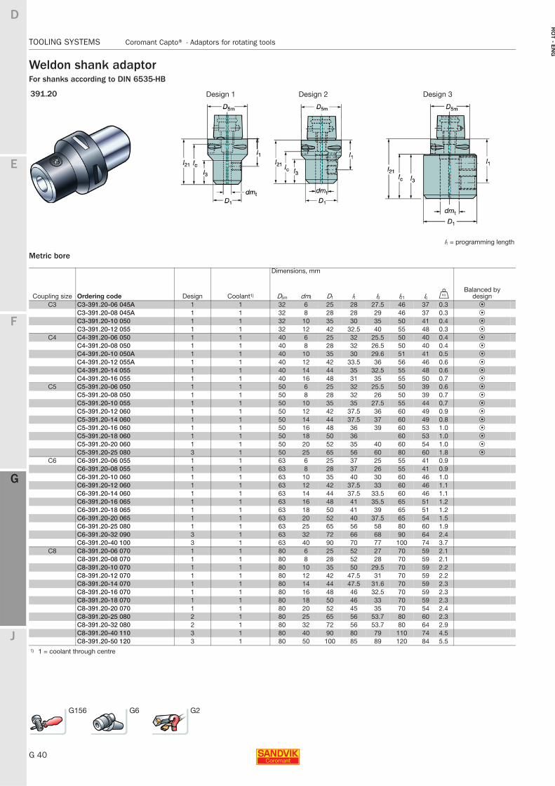
Weldon shank adaptorFor shanks according to DIN 6535-HB
Metric bore
391.20 Design 1 Design 2 Design 3
l1 = programming length
Dimensions, mm
Coupling size Ordering code Design Coolant1) D5m dmt D1 l1 l3 l21 lc UBalanced by
designC3 C3-391.20-06 045A 1 1 32 6 25 28 27.5 46 37 0.3 P
C3-391.20-08 045A 1 1 32 8 28 28 29 46 37 0.3 PC3-391.20-10 050 1 1 32 10 35 30 35 50 41 0.4 PC3-391.20-12 055 1 1 32 12 42 32.5 40 55 48 0.3 P
C4 C4-391.20-06 050 1 1 40 6 25 32 25.5 50 40 0.4 PC4-391.20-08 050 1 1 40 8 28 32 26.5 50 40 0.4 PC4-391.20-10 050A 1 1 40 10 35 30 29.6 51 41 0.5 PC4-391.20-12 055A 1 1 40 12 42 33.5 36 56 46 0.6 PC4-391.20-14 055 1 1 40 14 44 35 32.5 55 48 0.6 PC4-391.20-16 055 1 1 40 16 48 31 35 55 50 0.7 P
C5 C5-391.20-06 050 1 1 50 6 25 32 25.5 50 39 0.6 PC5-391.20-08 050 1 1 50 8 28 32 26 50 39 0.7 PC5-391.20-10 055 1 1 50 10 35 35 27.5 55 44 0.7 PC5-391.20-12 060 1 1 50 12 42 37.5 36 60 49 0.9 PC5-391.20-14 060 1 1 50 14 44 37.5 37 60 49 0.8 PC5-391.20-16 060 1 1 50 16 48 36 39 60 53 1.0 PC5-391.20-18 060 1 1 50 18 50 36 60 53 1.0 PC5-391.20-20 060 1 1 50 20 52 35 40 60 54 1.0 PC5-391.20-25 080 3 1 50 25 65 56 60 80 60 1.8 P
C6 C6-391.20-06 055 1 1 63 6 25 37 25 55 41 0.9C6-391.20-08 055 1 1 63 8 28 37 26 55 41 0.9C6-391.20-10 060 1 1 63 10 35 40 30 60 46 1.0C6-391.20-12 060 1 1 63 12 42 37.5 33 60 46 1.1C6-391.20-14 060 1 1 63 14 44 37.5 33.5 60 46 1.1C6-391.20-16 065 1 1 63 16 48 41 35.5 65 51 1.2C6-391.20-18 065 1 1 63 18 50 41 39 65 51 1.2C6-391.20-20 065 1 1 63 20 52 40 37.5 65 54 1.5C6-391.20-25 080 1 1 63 25 65 56 58 80 60 1.9C6-391.20-32 090 3 1 63 32 72 66 68 90 64 2.4C6-391.20-40 100 3 1 63 40 90 70 77 100 74 3.7
C8 C8-391.20-06 070 1 1 80 6 25 52 27 70 59 2.1C8-391.20-08 070 1 1 80 8 28 52 28 70 59 2.1C8-391.20-10 070 1 1 80 10 35 50 29.5 70 59 2.2C8-391.20-12 070 1 1 80 12 42 47.5 31 70 59 2.2C8-391.20-14 070 1 1 80 14 44 47.5 31.6 70 59 2.3C8-391.20-16 070 1 1 80 16 48 46 32.5 70 59 2.3C8-391.20-18 070 1 1 80 18 50 46 33 70 59 2.3C8-391.20-20 070 1 1 80 20 52 45 35 70 54 2.4C8-391.20-25 080 2 1 80 25 65 56 53.7 80 60 2.3C8-391.20-32 080 2 1 80 32 72 56 53.7 80 64 2.9C8-391.20-40 110 3 1 80 40 90 80 79 110 74 4.5C8-391.20-50 120 3 1 80 50 100 85 89 120 84 5.5
1) 1 = coolant through centre
G156 G6 G2
E
G 41
F
G
J
D
G
Coromant Capto® - Adaptors for rotating tools TOOLING SYSTEMS
RO
T -
EN
G
TOOLING SYSTEMS Coromant Capto® − Adaptors for rotating tools
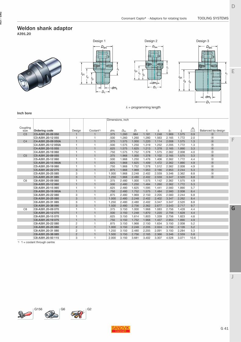
Weldon shank adaptorA391.20
Inch bore
Design 1 Design 2 Design 3
l1 = programming length
Dimensions, inch
Coupling size Ordering code Design Coolant1) dmt D5m D1 l1 l3 l21 lc V Balanced by designC3 C3-A391.20-09 050 1 1 .375 1.260 .984 1.181 1.248 1.969 1.575 0.9 P
C3-A391.20-12 055 1 1 .500 1.260 1.260 1.280 1.563 2.165 1.772 2.0 PC4 C4-A391.20-09 050A 1 1 .375 1.575 1.000 1.220 1.114 2.008 1.575 1.3 P
C4-A391.20-12 055A 1 1 .500 1.575 1.250 1.319 1.252 2.205 1.772 1.3 PC4-A391.20-15 055 1 1 .625 1.575 1.625 1.213 1.378 2.165 1.890 3.3 PC4-A391.20-19 060 1 1 .750 1.575 1.752 1.378 1.575 2.362 2.008 4.0 P
C5 C5-A391.20-09 055 1 1 .375 1.968 1.000 1.378 1.102 2.165 1.575 3.3 PC5-A391.20-12 060 1 1 .500 1.968 1.250 1.476 1.406 2.362 1.772 4.4 PC5-A391.20-15 060A 1 1 .625 1.968 1.625 1.409 1.472 2.362 1.890 4.9 PC5-A391.20-19 060 1 1 .750 1.968 1.752 1.378 1.512 2.362 2.008 4.9 PC5-A391.20-22 075 3 1 .875 1.968 1.969 1.953 2.166 2.953 2.244 5.3 PC5-A391.20-25 085 3 1 1.000 1.968 2.248 2.402 2.559 3.346 2.362 8.8 PC5-A391.20-31 085 3 1 1.250 1.968 2.480 2.402 2.559 3.347 2.520 8.8 P
C6 C6-A391.20-09 060 1 1 .375 2.480 1.000 1.575 1.142 2.362 1.575 4.9C6-A391.20-12 060 1 1 .500 2.480 1.250 1.484 1.260 2.362 1.772 5.3C6-A391.20-15 065 1 1 .625 2.480 1.625 1.595 1.441 2.560 1.890 5.7C6-A391.20-19 065A 1 1 .750 2.480 1.752 1.575 1.484 2.560 2.008 6.4C6-A391.20-22 080 3 1 .875 2.480 1.969 2.150 2.205 2.560 2.244 6.8C6-A391.20-25 085 3 1 1.000 2.480 2.248 2.402 2.402 3.347 2.262 8.4C6-A391.20-31 085 3 1 1.250 2.480 2.480 2.402 3.347 3.347 2.520 8.8C6-A391.20-38 090 3 1 1.500 2.480 2.756 2.362 2.677 3.543 2.717 9.7
C8 C8-A391.20-09 070 1 1 .375 3.150 1.000 1.968 1.083 2.756 1.428 4.4C8-A391.20-12 070 1 1 .500 3.150 1.248 1.870 1.220 2.756 1.628 4.4C8-A391.20-15 070 1 1 .625 3.150 1.614 1.803 1.339 2.756 1.823 4.6C8-A391.20-19 075 1 1 .750 3.150 1.752 1.968 1.437 2.953 1.890 4.9C8-A391.20-22 080 2 1 .875 3.150 1.968 2.150 1.634 3.150 2.008 5.2C8-A391.20-25 080 2 1 1.000 3.150 2.248 2.205 2.024 3.150 2.126 5.2C8-A391.20-31 080 2 1 1.250 3.150 2.480 2.205 2.091 3.150 2.284 5.3C8-A391.20-38 085 2 1 1.500 3.150 2.756 2.165 2.366 3.346 2.559 5.8C8-A391.20-50 115 3 1 2.000 3.150 3.681 3.402 3.307 4.528 3.071 10.6
1) 1 = coolant through centre
G156 G6 G2
G 42
TOOLING SYSTEMS Coromant Capto® - Adaptors for rotating tools
E
F
G
J
D
G
RO
T - E
NG
TOOLING SYSTEMS Coromant Capto® − Adaptors for rotating tools
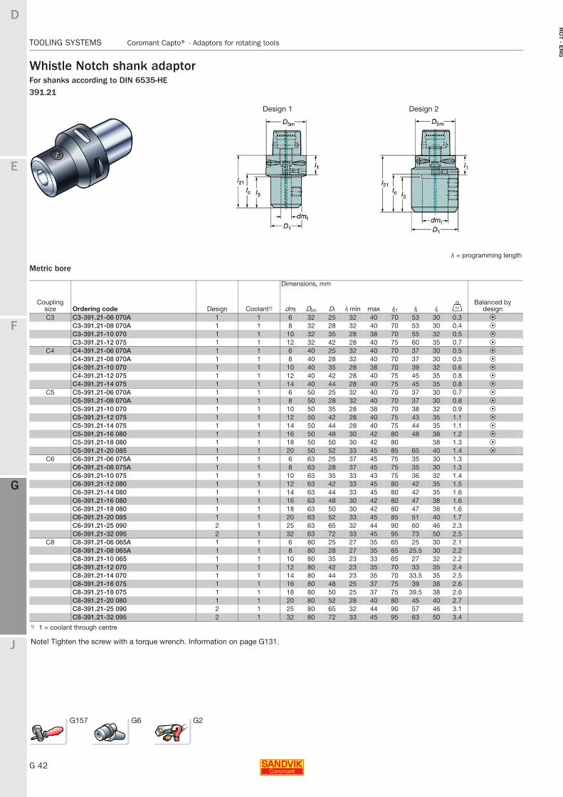
Whistle Notch shank adaptorFor shanks according to DIN 6535-HE391.21
Metric bore
Design 1 Design 2
l1 = programming length
Dimensions, mm
Coupling size Ordering code Design Coolant1) dmt D5m D1 l1 min max l21 l3 lc U
Balanced by design
C3 C3-391.21-06 070A 1 1 6 32 25 32 40 70 53 30 0.3 PC3-391.21-08 070A 1 1 8 32 28 32 40 70 53 30 0.4 PC3-391.21-10 070 1 1 10 32 35 28 38 70 55 32 0.5 PC3-391.21-12 075 1 1 12 32 42 28 40 75 60 35 0.7 P
C4 C4-391.21-06 070A 1 1 6 40 25 32 40 70 37 30 0.5 PC4-391.21-08 070A 1 1 8 40 28 32 40 70 37 30 0.5 PC4-391.21-10 070 1 1 10 40 35 28 38 70 39 32 0.6 PC4-391.21-12 075 1 1 12 40 42 28 40 75 45 35 0.8 PC4-391.21-14 075 1 1 14 40 44 28 40 75 45 35 0.8 P
C5 C5-391.21-06 070A 1 1 6 50 25 32 40 70 37 30 0.7 PC5-391.21-08 070A 1 1 8 50 28 32 40 70 37 30 0.8 PC5-391.21-10 070 1 1 10 50 35 28 38 70 38 32 0.9 PC5-391.21-12 075 1 1 12 50 42 28 40 75 43 35 1.1 PC5-391.21-14 075 1 1 14 50 44 28 40 75 44 35 1.1 PC5-391.21-16 080 1 1 16 50 48 30 42 80 48 38 1.2 PC5-391.21-18 080 1 1 18 50 50 30 42 80 38 1.3 PC5-391.21-20 085 1 1 20 50 52 33 45 85 65 40 1.4 P
C6 C6-391.21-06 075A 1 1 6 63 25 37 45 75 35 30 1.3C6-391.21-08 075A 1 1 8 63 28 37 45 75 35 30 1.3C6-391.21-10 075 1 1 10 63 35 33 43 75 36 32 1.4C6-391.21-12 080 1 1 12 63 42 33 45 80 42 35 1.5C6-391.21-14 080 1 1 14 63 44 33 45 80 42 35 1.6C6-391.21-16 080 1 1 16 63 48 30 42 80 47 38 1.6C6-391.21-18 080 1 1 18 63 50 30 42 80 47 38 1.6C6-391.21-20 085 1 1 20 63 52 33 45 85 51 40 1.7C6-391.21-25 090 2 1 25 63 65 32 44 90 60 46 2.3C6-391.21-32 095 2 1 32 63 72 33 45 95 73 50 2.5
C8 C8-391.21-06 065A 1 1 6 80 25 27 35 65 25 30 2.1C8-391.21-08 065A 1 1 8 80 28 27 35 65 25.5 30 2.2C8-391.21-10 065 1 1 10 80 35 23 33 65 27 32 2.2C8-391.21-12 070 1 1 12 80 42 23 35 70 33 35 2.4C8-391.21-14 070 1 1 14 80 44 23 35 70 33.5 35 2.5C8-391.21-16 075 1 1 16 80 48 25 37 75 39 38 2.6C8-391.21-18 075 1 1 18 80 50 25 37 75 39.5 38 2.6C8-391.21-20 080 1 1 20 80 52 28 40 80 45 40 2.7C8-391.21-25 090 2 1 25 80 65 32 44 90 57 46 3.1C8-391.21-32 095 2 1 32 80 72 33 45 95 63 50 3.4
1) 1 = coolant through centre
Note! Tighten the screw with a torque wrench. Information on page G131.
G157 G6 G2
E
G 43
F
G
J
D
G
Coromant Capto® - Adaptors for rotating tools TOOLING SYSTEMS
RO
T -
EN
G
TOOLING SYSTEMS Coromant Capto® − Adaptors for rotating tools
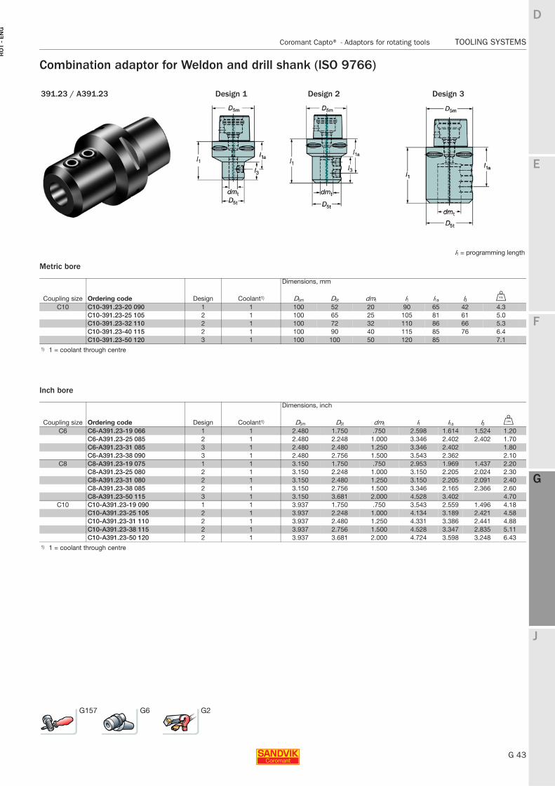
Combination adaptor for Weldon and drill shank (ISO 9766)
Metric bore
Inch bore
391.23 / A391.23 Design 1 Design 2 Design 3
l1 = programming length
Dimensions, mm
Coupling size Ordering code Design Coolant1) D5m D5t dmt l1 l1a l3 U
C10 C10-391.23-20 090 1 1 100 52 20 90 65 42 4.3C10-391.23-25 105 2 1 100 65 25 105 81 61 5.0C10-391.23-32 110 2 1 100 72 32 110 86 66 5.3C10-391.23-40 115 2 1 100 90 40 115 85 76 6.4C10-391.23-50 120 3 1 100 100 50 120 85 7.1
1) 1 = coolant through centre
Dimensions, inch
Coupling size Ordering code Design Coolant1) D5m D5t dmt l1 l1a l3 V
C6 C6-A391.23-19 066 1 1 2.480 1.750 .750 2.598 1.614 1.524 1.20C6-A391.23-25 085 2 1 2.480 2.248 1.000 3.346 2.402 2.402 1.70C6-A391.23-31 085 3 1 2.480 2.480 1.250 3.346 2.402 1.80C6-A391.23-38 090 3 1 2.480 2.756 1.500 3.543 2.362 2.10
C8 C8-A391.23-19 075 1 1 3.150 1.750 .750 2.953 1.969 1.437 2.20C8-A391.23-25 080 2 1 3.150 2.248 1.000 3.150 2.205 2.024 2.30C8-A391.23-31 080 2 1 3.150 2.480 1.250 3.150 2.205 2.091 2.40C8-A391.23-38 085 2 1 3.150 2.756 1.500 3.346 2.165 2.366 2.60C8-A391.23-50 115 3 1 3.150 3.681 2.000 4.528 3.402 4.70
C10 C10-A391.23-19 090 1 1 3.937 1.750 .750 3.543 2.559 1.496 4.18C10-A391.23-25 105 2 1 3.937 2.248 1.000 4.134 3.189 2.421 4.58C10-A391.23-31 110 2 1 3.937 2.480 1.250 4.331 3.386 2.441 4.88C10-A391.23-38 115 2 1 3.937 2.756 1.500 4.528 3.347 2.835 5.11C10-A391.23-50 120 2 1 3.937 3.681 2.000 4.724 3.598 3.248 6.43
1) 1 = coolant through centre
G157 G6 G2
G 44
TOOLING SYSTEMS Coromant Capto® - Adaptors for rotating tools
E
F
G
J
D
G
RO
T - E
NG
TOOLING SYSTEMS Coromant Capto® − Adaptors for rotating tools
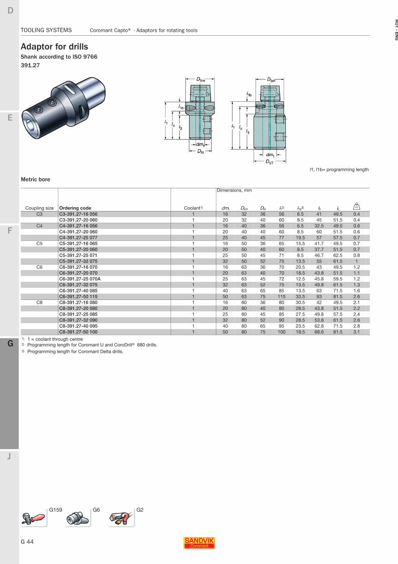
Adaptor for drillsShank according to ISO 9766391.27
Metric bore
l1, l1b= programming length
Dimensions, mm
Coupling size Ordering code Coolant1) dmt D5m D5t l12) l1b3) l3 lc U
C3 C3-391.27-16 056 1 16 32 36 56 6.5 41 49.5 0.4C3-391.27-20 060 1 20 32 40 60 8.5 45 51.5 0.4
C4 C4-391.27-16 056 1 16 40 36 56 6.5 32.5 49.5 0.6C4-391.27-20 060 1 20 40 40 60 8.5 60 51.5 0.6C4-391.27-25 077 1 25 40 45 77 19.5 57 57.5 0.7
C5 C5-391.27-16 065 1 16 50 36 65 15.5 41.7 49.5 0.7C5-391.27-20 060 1 20 50 40 60 8.5 37.7 51.5 0.7C5-391.27-25 071 1 25 50 45 71 8.5 46.7 62.5 0.8C5-391.27-32 075 1 32 50 52 75 13.5 55 61.5 1
C6 C6-391.27-16 070 1 16 63 36 70 20.5 43 49.5 1.2C6-391.27-20 070 1 20 63 40 70 18.5 43.8 51.5 1.1C6-391.27-25 070A 1 25 63 45 72 12.5 45.8 59.5 1.2C6-391.27-32 075 1 32 63 52 75 13.5 49.8 61.5 1.3C6-391.27-40 085 1 40 63 65 85 13.5 63 71.5 1.6C6-391.27-50 115 1 50 63 75 115 33.5 93 81.5 2.6
C8 C8-391.27-16 080 1 16 80 36 80 30.5 42 49.5 2.1C8-391.27-20 080 1 20 80 40 80 28.5 43.8 51.5 2.2C8-391.27-25 085 1 25 80 45 85 27.5 49.8 57.5 2.4C8-391.27-32 090 1 32 80 52 90 28.5 53.8 61.5 2.6C8-391.27-40 095 1 40 80 65 95 23.5 62.8 71.5 2.8C8-391.27-50 100 1 50 80 75 100 18.5 68.6 81.5 3.1
1) 1 = coolant through centre2) Programming length for Coromant U and CoroDrill® 880 drills.3) Programming length for Coromant Delta drills.
G159 G6 G2
E
G 45
F
G
J
D
G
Coromant Capto® - Adaptors for rotating tools TOOLING SYSTEMS
RO
T -
EN
G
TOOLING SYSTEMS Coromant Capto® − Adaptors for rotating tools
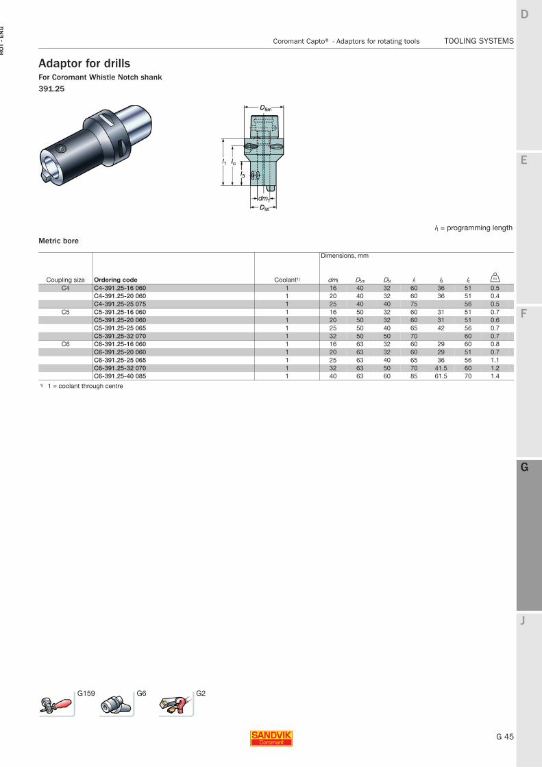
Adaptor for drillsFor Coromant Whistle Notch shank391.25
Metric bore
l1 = programming length
Dimensions, mm
Coupling size Ordering code Coolant1) dmt D5m D5t l1 l3 lc U
C4 C4-391.25-16 060 1 16 40 32 60 36 51 0.5C4-391.25-20 060 1 20 40 32 60 36 51 0.4C4-391.25-25 075 1 25 40 40 75 56 0.5
C5 C5-391.25-16 060 1 16 50 32 60 31 51 0.7C5-391.25-20 060 1 20 50 32 60 31 51 0.6C5-391.25-25 065 1 25 50 40 65 42 56 0.7C5-391.25-32 070 1 32 50 50 70 60 0.7
C6 C6-391.25-16 060 1 16 63 32 60 29 60 0.8C6-391.25-20 060 1 20 63 32 60 29 51 0.7C6-391.25-25 065 1 25 63 40 65 36 56 1.1C6-391.25-32 070 1 32 63 50 70 41.5 60 1.2C6-391.25-40 085 1 40 63 60 85 61.5 70 1.4
1) 1 = coolant through centre
G159 G6 G2
G 46
TOOLING SYSTEMS Coromant Capto® - Adaptors for rotating tools
E
F
G
J
D
G
RO
T - E
NG
TOOLING SYSTEMS Coromant Capto® − Adaptors for rotating tools
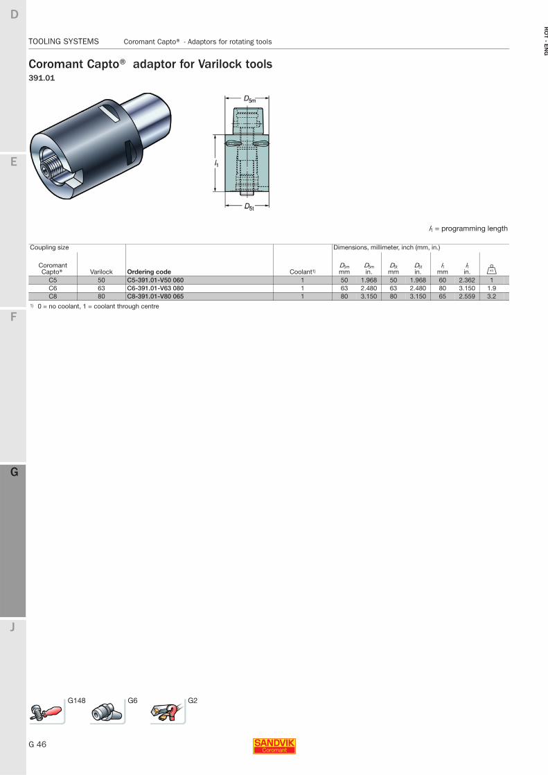
Coromant Capto® adaptor for Varilock tools391.01
l1 = programming length
Coupling size Dimensions, millimeter, inch (mm, in.)
Coromant Capto® Varilock Ordering code Coolant1)
D5mmm
D5min.
D5tmm
D5tin.
l1mm
l1in. U
C5 50 C5-391.01-V50 060 1 50 1.968 50 1.968 60 2.362 1C6 63 C6-391.01-V63 080 1 63 2.480 63 2.480 80 3.150 1.9C8 80 C8-391.01-V80 065 1 80 3.150 80 3.150 65 2.559 3.2
1) 0 = no coolant, 1 = coolant through centre
G148 G6 G2
E
G 47
F
G
J
D
G
Adaptors for rotating tools TOOLING SYSTEMS
RO
T -
EN
G
TOOLING SYSTEMS Adaptors for rotating tools
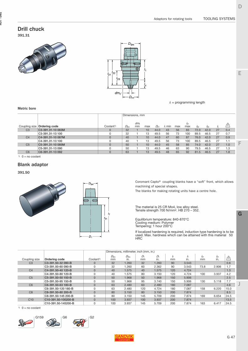
Drill chuck391.31
Metric bore
Blank adaptor
391.50
l1 = programming length
Dimensions, mm
Coupling size Ordering code Coolant1) D5m
dmt min max D21 l1 min max
l21 max l22 l23 lc U
C3 C3-391.31-10 083M 0 32 1 10 44.0 43 56 83 72.0 42.0 27 0.4C3-391.31-13 100 0 32 1 13 49.5 56 73 100 89.5 46.5 27 0.7
C4 C4-391.31-10 087M 0 40 1 10 44.0 47 60 87 76.0 42.0 27 0.9C4-391.31-13 100 0 40 1 13 49.5 56 73 100 89.5 46.5 27 1.1
C5 C5-391.31-10 085M 0 50 1 10 44.0 45 58 85 74.0 42.0 27 1.0C5-391.31-13 090 0 50 1 13 49.5 46 63 90 79.5 46.5 27 1.3
C6 C6-391.31-13 092 0 63 1 13 49.5 48 65 92 81.5 46.5 27 1.81) 0 = no coolant
Coromant Capto® coupling blanks have a “soft” front, which allows machining of special shapes.The blanks for making rotating units have a centre hole.
The material is 25 CR Mo4, low alloy steel.Tensile strength 700 N/mm2. HB 270 – 352.
Equilibrium temperature: 840-870°CCooling medium: PolymerTempering: 1 hour 200°C
If localized hardening is required, induction type hardening is to be used. Max. hardness which can be attained with this material 50 HRC
Dimensions, millimeter, inch (mm, in.)
Coupling size Ordering code Coolant1)D5mmm
D5min.
D1mm
D1in.
l7mm
l7in.
l21 mm
l21 in. U
C3 C3-391.50-32 090-B 0 32 1.260 32 1.260 90 3.543 0.6C3-391.50-60 090-B 0 32 1.260 60 2.362 90 3.543 73.8 2.906 1.7
C4 C4-391.50-40 120-B 0 40 1.575 40 1.575 120 4.724 1.3C4-391.50-80 120-B 0 40 1.575 80 3.150 120 4.724 100 3.937 4.2
C5 C5-391.50-50 150-B 0 50 1.968 50 1.968 150 5.906 2.5C5-391.50-95 150-B 0 50 1.968 95 3.740 150 5.906 130 5.118 7.7
C6 C6-391.50-63 180-B 0 63 2.480 63 2.480 180 7.087 4.6C6-391.50-120 180-B 0 63 2.480 120 4.724 180 7.087 158 6.220 15.0
C8 C8-391.50-80 200-B 0 80 3.150 80 3.150 200 7.874 8.5C8-391.50-145 200-B 0 80 3.150 145 5.709 200 7.874 169 6.654 24.5
C10 C10-391.50-100200-B 0 100 3.937 100 3.937 200 7.874 13.5C10-391.50-145200-B 0 100 3.937 145 5.709 200 7.874 163 6.417 24.5
1) 0 = no coolant
G159 G6 G2
G 48
TOOLING SYSTEMS Solid holding tools - Overview
E
F
G
J
D
G
RO
T - E
NG
TOOLING SYSTEMS Solid holding tools - Overview
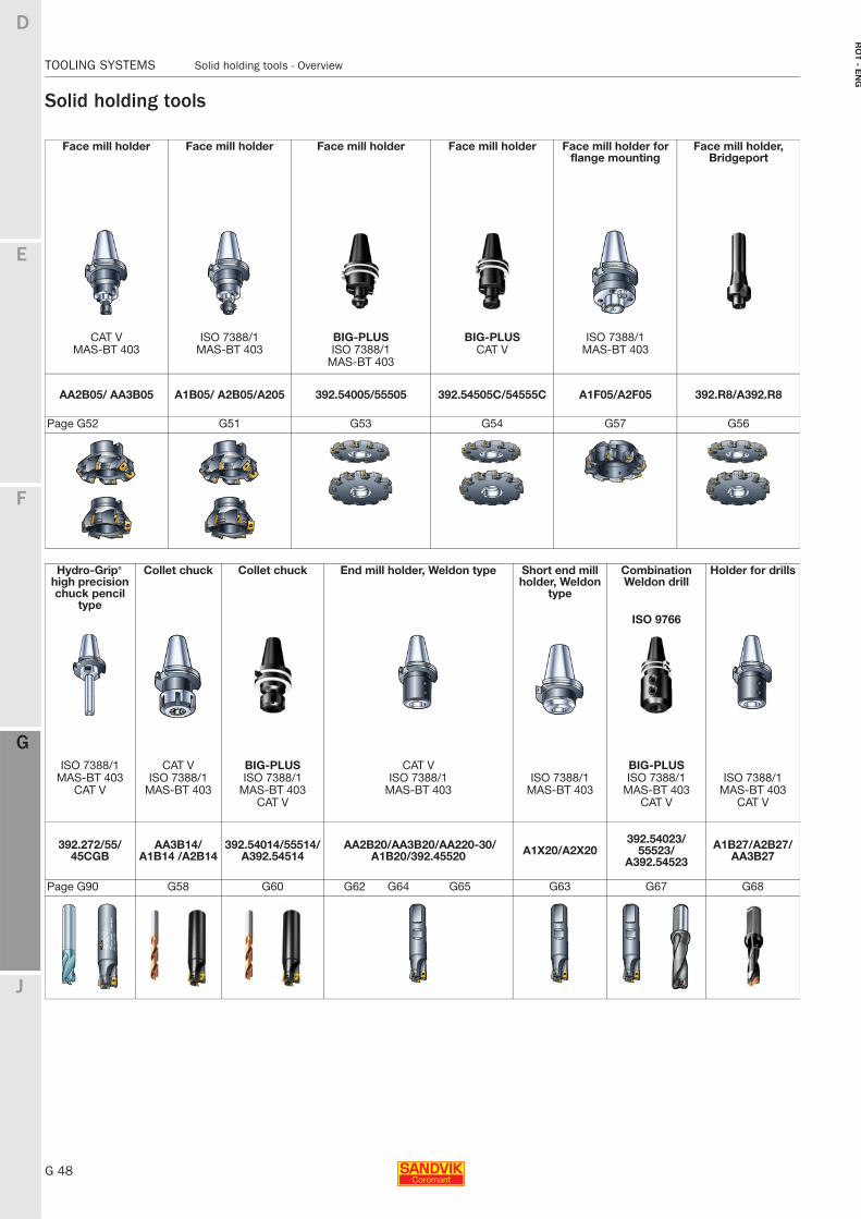
Solid holding tools
Face mill holder Face mill holder Face mill holder Face mill holder Face mill holder for flange mounting
Face mill holder, Bridgeport
CAT V ISO 7388/1 BIG-PLUS BIG-PLUS ISO 7388/1MAS-BT 403 MAS-BT 403 ISO 7388/1 CAT V MAS-BT 403
MAS-BT 403
AA2B05/ AA3B05 A1B05/ A2B05/A205 392.54005/55505 392.54505C/54555C A1F05/A2F05 392.R8/A392.R8
Page G52 G51 G53 G54 G57 G56
Hydro-Grip® high precision chuck pencil
type
Collet chuck Collet chuck End mill holder, Weldon type Short end mill holder, Weldon
type
Combination Weldon drill
Holder for drills
ISO 9766
ISO 7388/1 CAT V BIG-PLUS CAT V BIG-PLUSMAS-BT 403 ISO 7388/1 ISO 7388/1 ISO 7388/1 ISO 7388/1 ISO 7388/1 ISO 7388/1
CAT V MAS-BT 403 MAS-BT 403 MAS-BT 403 MAS-BT 403 MAS-BT 403 MAS-BT 403CAT V CAT V CAT V
392.272/55/45CGB
AA3B14/A1B14 /A2B14
392.54014/55514/A392.54514
AA2B20/AA3B20/AA220-30/A1B20/392.45520 A1X20/A2X20
392.54023/55523/
A392.54523
A1B27/A2B27/AA3B27
Page G90 G58 G60 G62 G64 G65 G63 G67 G68
E
G 49
F
G
J
D
G
Solid holding tools - Overview TOOLING SYSTEMS
RO
T -
EN
G
TOOLING SYSTEMS Solid holding tools - Overview
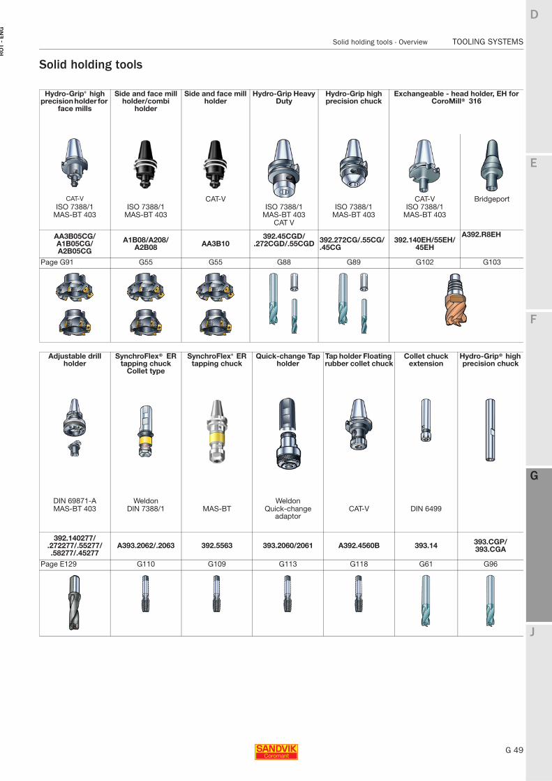
Solid holding tools
Hydro-Grip® high precision holder for
face mills
Side and face mill holder/combi
holder
Side and face mill holder
Hydro-Grip Heavy Duty
Hydro-Grip high precision chuck
Exchangeable - head holder, EH for CoroMill® 316
CAT-V CAT-V CAT-V BridgeportISO 7388/1 ISO 7388/1 ISO 7388/1 ISO 7388/1 ISO 7388/1
MAS-BT 403 MAS-BT 403 MAS-BT 403 MAS-BT 403 MAS-BT 403CAT V
AA3B05CG/A1B05CG/A2B05CG
A1B08/A208/A2B08 AA3B10
392.45CGD/.272CGD/.55CGD 392.272CG/.55CG/
.45CG392.140EH/55EH/
45EH
A392.R8EH
Page G91 G55 G55 G88 G89 G102 G103
Adjustable drill holder
SynchroFlex® ER tapping chuck
Collet type
SynchroFlex® ER tapping chuck
Quick-change Tap holder
Tap holder Floating rubber collet chuck
Collet chuck extension
Hydro-Grip® high precision chuck
DIN 69871-A Weldon WeldonMAS-BT 403 DIN 7388/1 MAS-BT Quick-change
adaptorCAT-V DIN 6499
392.140277/.272277/.55277/.58277/.45277
A393.2062/.2063 392.5563 393.2060/2061 A392.4560B 393.14 393.CGP/393.CGA
Page E129 G110 G109 G113 G118 G61 G96
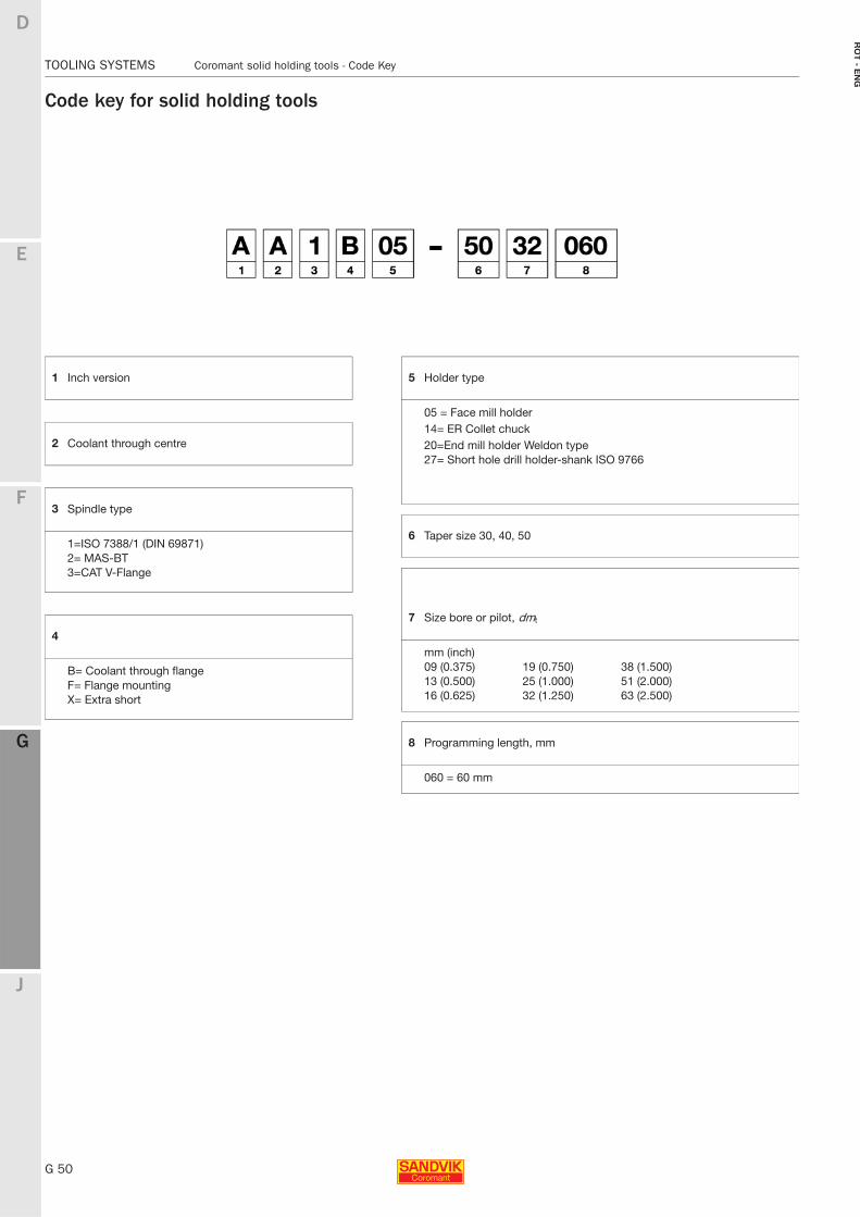
G 50
TOOLING SYSTEMS Coromant solid holding tools - Code Key
E
F
G
J
D
G
RO
T - E
NG
TOOLING SYSTEMS Coromant solid holding tools - Code Key
Code key for solid holding tools
1 Inch version
2 Coolant through centre
3 Spindle type
1=ISO 7388/1 (DIN 69871) 2= MAS-BT3=CAT V-Flange
4
B= Coolant through flangeF= Flange mountingX= Extra short
5 Holder type
05 = Face mill holder14= ER Collet chuck20=End mill holder Weldon type27= Short hole drill holder-shank ISO 9766
6 Taper size 30, 40, 50
7 Size bore or pilot, dmt
mm (inch)09 (0.375) 19 (0.750) 38 (1.500)13 (0.500) 25 (1.000) 51 (2.000)16 (0.625) 32 (1.250) 63 (2.500)
8 Programming length, mm
060 = 60 mm
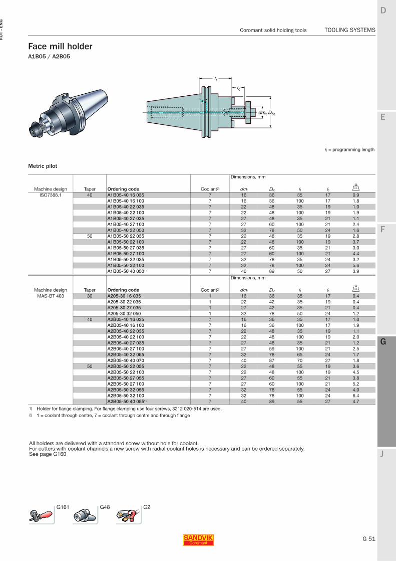
E
G 51
F
G
J
D
G
Coromant solid holding tools TOOLING SYSTEMS
RO
T -
EN
G
TOOLING SYSTEMS Coromant solid holding tools
Face mill holderA1B05 / A2B05
Metric pilot
l1 = programming length
Dimensions, mm
Machine design Taper Ordering code Coolant2) dmt D5t l1 lc U
ISO7388.1 40 A1B05-40 16 035 7 16 36 35 17 0.9A1B05-40 16 100 7 16 36 100 17 1.8A1B05-40 22 035 7 22 48 35 19 1.0A1B05-40 22 100 7 22 48 100 19 1.9A1B05-40 27 035 7 27 48 35 21 1.1A1B05-40 27 100 7 27 60 100 21 2.4A1B05-40 32 050 7 32 78 50 24 1.6
50 A1B05-50 22 035 7 22 48 35 19 2.8A1B05-50 22 100 7 22 48 100 19 3.7A1B05-50 27 035 7 27 60 35 21 3.0A1B05-50 27 100 7 27 60 100 21 4.4A1B05-50 32 035 7 32 78 35 24 3.2A1B05-50 32 100 7 32 78 100 24 5.6A1B05-50 40 0501) 7 40 89 50 27 3.9
Dimensions, mm
Machine design Taper Ordering code Coolant2) dmt D5t l1 lc U
MAS-BT 403 30 A205-30 16 035 1 16 36 35 17 0.4A205-30 22 035 1 22 42 35 19 0.4A205-30 27 035 1 27 42 35 21 0.4A205-30 32 050 1 32 78 50 24 1.2
40 A2B05-40 16 035 7 16 36 35 17 1.0A2B05-40 16 100 7 16 36 100 17 1.9A2B05-40 22 035 7 22 48 35 19 1.1A2B05-40 22 100 7 22 48 100 19 2.0A2B05-40 27 035 7 27 48 35 21 1.2A2B05-40 27 100 7 27 59 100 21 2.5A2B05-40 32 065 7 32 78 65 24 1.7A2B05-40 40 070 7 40 87 70 27 1.8
50 A2B05-50 22 055 7 22 48 55 19 3.6A2B05-50 22 100 7 22 48 100 19 4.5A2B05-50 27 055 7 27 60 55 21 3.8A2B05-50 27 100 7 27 60 100 21 5.2A2B05-50 32 055 7 32 78 55 24 4.0A2B05-50 32 100 7 32 78 100 24 6.4A2B05-50 40 0551) 7 40 89 55 27 4.7
1) Holder for flange clamping. For flange clamping use four screws, 3212 020-514 are used.2) 1 = coolant through centre, 7 = coolant through centre and through flange
All holders are delivered with a standard screw without hole for coolant.For cutters with coolant channels a new screw with radial coolant holes is necessary and can be ordered separately.See page G160
G161 G48 G2
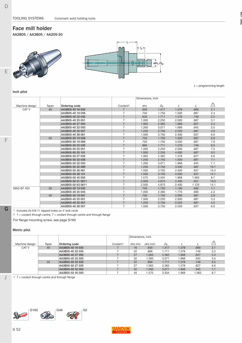
G 52
TOOLING SYSTEMS Coromant solid holding tools
E
F
G
J
D
G
RO
T - E
NG
TOOLING SYSTEMS Coromant solid holding tools
Face mill holderAA2B05 / AA3B05 / AA205-30
Inch pilot
Metric pilot
l1 = programming length
Dimensions, inch
Machine design Taper Ordering code Coolant2) dmt D5t l1 lc V
CAT V 40 AA3B05-40 16 035 7 .630 1.417 1.378 .669 2.1AA3B05-40 19 038 7 .750 1.750 1.500 .687 2.4AA3B05-40 22 035 7 .630 1.711 1.378 .748 2.2AA3B05-40 25 051 7 1.000 2.250 2.000 .687 3.1AA3B05-40 27 050 7 1.063 2.362 1.968 .827 2.4AA3B05-40 32 050 7 1.260 3.071 1.968 .945 3.5AA3B05-40 32 057 7 1.250 2.750 2.250 .687 4.0AA3B05-40 38 061 7 1.500 3.750 2.400 .937 6.0
50 AA3B05-50 19 038 7 .750 1.750 1.500 .687 6.8AA3B05-50 19 089 7 .750 1.750 3.500 .687 7.9AA3B05-50 22 035 7 .866 1.711 1.378 .748 6.5AA3B05-50 25 051 7 1.000 2.250 2.000 .687 7.5AA3B05-50 25 101 7 1.000 2.250 4.000 .687 9.5AA3B05-50 27 035 7 1.063 2.362 1.378 .827 6.6AA3B05-50 32 038 7 1.250 2.750 1.500 .687 7.1AA3B05-50 32 050 7 1.260 3.071 1.968 .945 7.1AA3B05-50 32 089 7 1.250 2.750 3.500 .687 10.1AA3B05-50 38 061 7 1.500 3.750 2.400 .937 10.4AA3B05-50 38 101 7 1.500 3.750 4.000 .937 14.1AA3B05-50 40 050 7 1.575 3.504 1.968 1.063 8.7AA3B05-50 51 0611) 7 2.000 4.875 2.400 .937 13.0AA3B05-50 63 0611) 7 2.500 4.875 2.400 1.125 14.1
MAS-BT 403 30 AA2B05-30 19 030 1 .750 1.750 1.190 .690 1.1AA2B05-30 25 045 1 1.000 2.390 1.770 .690 2.2
40 AA2B05-40 19 051 7 .750 1.750 2.000 .687 2.9AA2B05-40 25 051 7 1.000 2.250 2.000 .687 3.3AA2B05-40 32 057 7 1.250 2.750 2.250 .687 4.2AA2B05-40 38 057 7 1.500 3.750 2.250 .937 6.0
1) Includes (4) 5/8-11 tapped holes on 4¨ bolt circle2) 1 = coolant through centre, 7 = coolant through centre and through flange
For flange mounting screw, see page G160
Dimensions, inch
Machine design Taper Ordering code Coolant1) dmt mm dmt inch D5t l1 lc V
CAT V 40 AA3B05-40 16 035 7 16 .630 1.417 1.378 .669 2.1AA3B05-40 22 035 7 22 .866 1.711 1.378 .748 2.2AA3B05-40 27 050 7 27 1.063 2.362 1.968 .827 2.4AA3B05-40 32 050 7 32 1.260 3.071 1.968 .945 3.5
50 AA3B05-50 22 035 7 22 .866 1.711 1.378 .748 6.5AA3B05-50 27 035 7 27 1.063 2.362 1.378 .827 6.6AA3B05-50 32 050 7 32 1.260 3.071 1.968 .945 7.1AA3B05-50 40 050 7 40 1.575 3.504 1.968 1.063 8.7
1) 7 = coolant through centre and through flange
G160 G48 G2
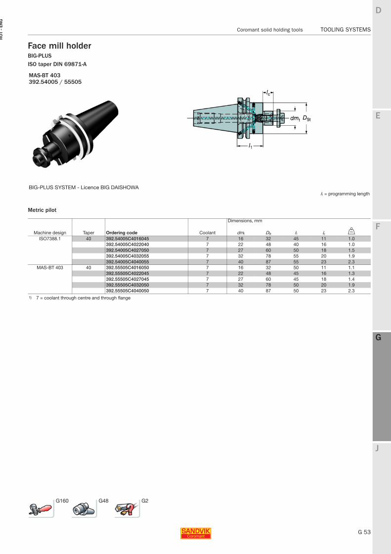
E
G 53
F
G
J
D
G
Coromant solid holding tools TOOLING SYSTEMS
RO
T -
EN
G
TOOLING SYSTEMS Coromant solid holding tools
Face mill holderBIG-PLUSISO taper DIN 69871-A
Metric pilot
MAS-BT 403392.54005 / 55505
BIG-PLUS SYSTEM - Licence BIG DAISHOWAl1 = programming length
Dimensions, mm
Machine design Taper Ordering code Coolant dmt D5t l1 lc U
ISO7388.1 40 392.54005C4016045 7 16 32 45 11 1.0392.54005C4022040 7 22 48 40 16 1.0392.54005C4027050 7 27 60 50 18 1.5392.54005C4032055 7 32 78 55 20 1.9392.54005C4040055 7 40 87 55 23 2.3
MAS-BT 403 40 392.55505C4016050 7 16 32 50 11 1.1392.55505C4022045 7 22 48 45 16 1.3392.55505C4027045 7 27 60 45 18 1.4392.55505C4032050 7 32 78 50 20 1.9392.55505C4040050 7 40 87 50 23 2.3
1) 7 = coolant through centre and through flange
G160 G48 G2
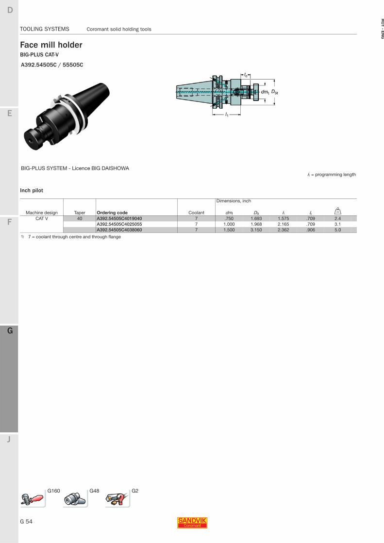
G 54
TOOLING SYSTEMS Coromant solid holding tools
E
F
G
J
D
G
RO
T - E
NG
TOOLING SYSTEMS Coromant solid holding tools
Face mill holderBIG-PLUS CAT-V
Inch pilot
A392.54505C / 55505C
BIG-PLUS SYSTEM - Licence BIG DAISHOWAl1 = programming length
Dimensions, inch
Machine design Taper Ordering code Coolant dmt D5t l1 lc V
CAT V 40 A392.54505C4019040 7 .750 1.693 1.575 .709 2.4A392.54505C4025055 7 1.000 1.968 2.165 .709 3.1A392.54505C4038060 7 1.500 3.150 2.362 .906 5.0
1) 7 = coolant through centre and through flange
G160 G48 G2
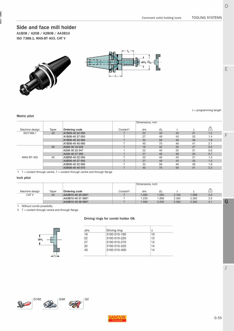
E
G 55
F
G
J
D
G
Coromant solid holding tools TOOLING SYSTEMS
RO
T -
EN
G
TOOLING SYSTEMS Coromant solid holding tools
Side and face mill holderA1B08 / A208 / A2B08 / AA3B10ISO 7388.1, MAS-BT 403, CAT V
Metric pilot
Inch pilot
l1 = programming length
Dimensions, mm
Machine design Taper Ordering code Coolant1) dmt D5t l1 lc U
ISO7388.1 40 A1B08-40 22 055 7 22 40 43 31 1.2A1B08-40 27 055 7 27 48 43 33 1.4A1B08-40 32 060 7 32 58 46 38 1.8A1B08-40 40 060 7 40 70 46 41 2.1
MAS-BT 403
30 A208-30 16 045 1 16 32 35 27 0.5A208-30 22 047 1 22 40 35 31 0.6A208-30 27 050 1 27 48 38 33 0.7
40 A2B08-40 22 055 7 22 40 43 31 1.3A2B08-40 27 055 7 27 48 43 33 1.5A2B08-40 32 060 7 32 58 46 38 1.8A2B08-40 40 070 7 40 70 56 41 2.3
1) 1 = coolant through centre, 7 = coolant through centre and through flange
Dimensions, inch
Machine design Taper Ordering code Coolant2) dmt D5t l1 lc V
CAT V 40 AA3B10-40 25 0551) 7 1.000 1.693 2.165 1.968 2.9AA3B10-40 31 0601) 7 1.250 1.890 2.362 2.362 3.5AA3B10-40 38 0601) 7 1.500 2.205 2.362 2.362 4.1
1) Without combi possibility2) 7 = coolant through centre and through flange
Driving rings for combi holder 08.
dmt Driving ring l116 3193 010-160 1022 3193 010-220 1227 3193 010-270 1232 3193 010-320 1440 3193 010-400 14
G160 G48 G2
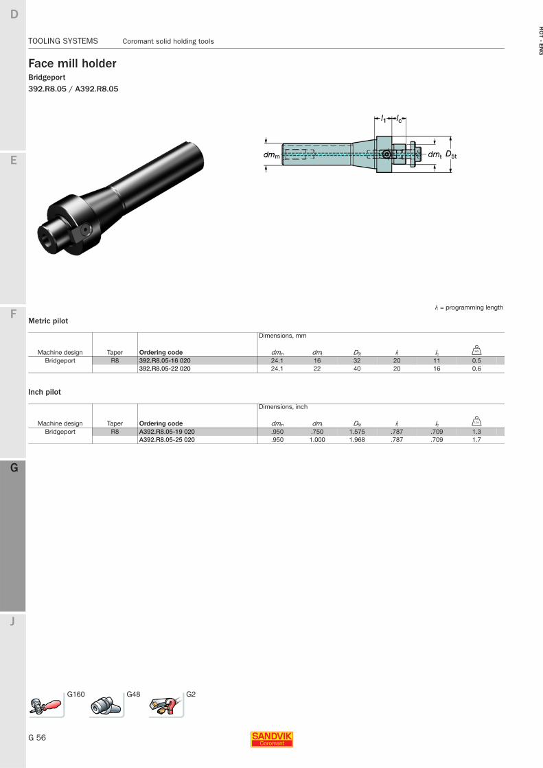
G 56
TOOLING SYSTEMS Coromant solid holding tools
E
F
G
J
D
G
RO
T - E
NG
TOOLING SYSTEMS Coromant solid holding tools
Face mill holderBridgeport392.R8.05 / A392.R8.05
Metric pilot
Inch pilot
l1 = programming length
Dimensions, mm
Machine design Taper Ordering code dmm dmt D5t l1 lc U
Bridgeport R8 392.R8.05-16 020 24.1 16 32 20 11 0.5392.R8.05-22 020 24.1 22 40 20 16 0.6
Dimensions, inch
Machine design Taper Ordering code dmm dmt D5t l1 lc V
Bridgeport R8 A392.R8.05-19 020 .950 .750 1.575 .787 .709 1.3A392.R8.05-25 020 .950 1.000 1.968 .787 .709 1.7
G160 G48 G2
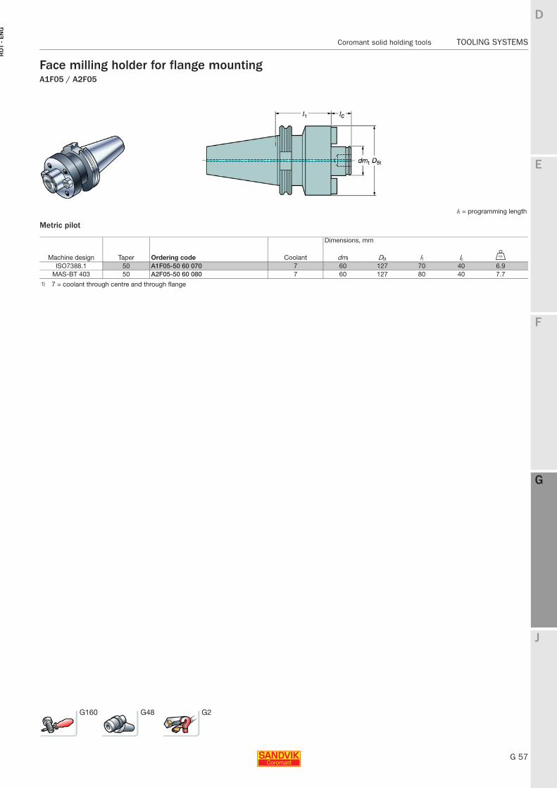
E
G 57
F
G
J
D
G
Coromant solid holding tools TOOLING SYSTEMS
RO
T -
EN
G
TOOLING SYSTEMS Coromant solid holding tools
Face milling holder for flange mountingA1F05 / A2F05
Metric pilot
l1 = programming length
Dimensions, mm
Machine design Taper Ordering code Coolant dmt D5t l1 lc U
ISO7388.1 50 A1F05-50 60 070 7 60 127 70 40 6.9MAS-BT 403 50 A2F05-50 60 080 7 60 127 80 40 7.7
1) 7 = coolant through centre and through flange
G160 G48 G2
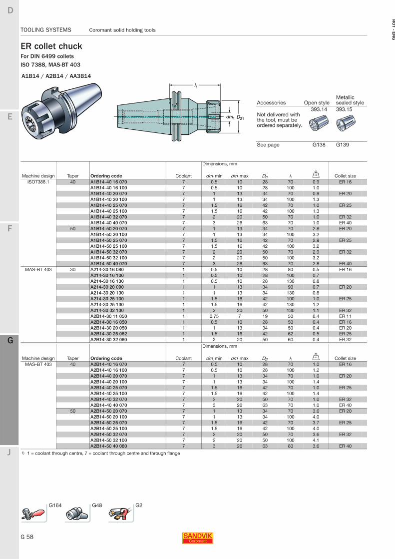
G 58
TOOLING SYSTEMS Coromant solid holding tools
E
F
G
J
D
G
RO
T - E
NG
TOOLING SYSTEMS Coromant solid holding tools
ER collet chuckFor DIN 6499 colletsISO 7388, MAS-BT 403
A1B14 / A2B14 / AA3B14
Accessories Open styleMetallic sealed style
393.14 393.15Not delivered with the tool, must be ordered separately.
See page G138 G139
Dimensions, mm
Machine design Taper Ordering code Coolant dmt min dmt max D21 l1 U Collet sizeISO7388.1 40 A1B14-40 16 070 7 0.5 10 28 70 0.9 ER 16
A1B14-40 16 100 7 0.5 10 28 100 1.0A1B14-40 20 070 7 1 13 34 70 0.9 ER 20A1B14-40 20 100 7 1 13 34 100 1.3A1B14-40 25 070 7 1.5 16 42 70 1.0 ER 25A1B14-40 25 100 7 1.5 16 42 100 1.3A1B14-40 32 070 7 2 20 50 70 1.0 ER 32A1B14-40 40 070 7 3 26 63 70 1.0 ER 40
50 A1B14-50 20 070 7 1 13 34 70 2.8 ER 20A1B14-50 20 100 7 1 13 34 100 3.2A1B14-50 25 070 7 1.5 16 42 70 2.9 ER 25A1B14-50 25 100 7 1.5 16 42 100 3.2A1B14-50 32 070 7 2 20 50 70 2.9 ER 32A1B14-50 32 100 7 2 20 50 100 3.2A1B14-50 40 070 7 3 26 63 70 2.8 ER 40
MAS-BT 403 30 A214-30 16 080 1 0.5 10 28 80 0.5 ER 16A214-30 16 100 1 0.5 10 28 100 0.7A214-30 16 130 1 0.5 10 28 130 0.8A214-30 20 090 1 1 13 34 90 0.7 ER 20A214-30 20 130 1 1 13 34 130 0.8A214-30 25 100 1 1.5 16 42 100 1.0 ER 25A214-30 25 130 1 1.5 16 42 130 1.2A214-30 32 130 1 2 20 50 130 1.1 ER 32A2B14-30 11 050 1 0.75 7 19 50 0.4 ER 11A2B14-30 16 050 1 0.5 10 28 50 0.4 ER 16A2B14-30 20 050 1 1 13 34 50 0.4 ER 20A2B14-30 25 062 1 1.5 16 42 62 0.5 ER 25A2B14-30 32 060 1 2 20 50 60 0.4 ER 32
Dimensions, mm
Machine design Taper Ordering code Coolant dmt min dmt max D21 l1 U Collet sizeMAS-BT 403 40 A2B14-40 16 070 7 0.5 10 28 70 1.0 ER 16
A2B14-40 16 100 7 0.5 10 28 100 1.2A2B14-40 20 070 7 1 13 34 70 1.0 ER 20A2B14-40 20 100 7 1 13 34 100 1.4A2B14-40 25 070 7 1.5 16 42 70 1.0 ER 25A2B14-40 25 100 7 1.5 16 42 100 1.4A2B14-40 32 070 7 2 20 50 70 1.0 ER 32A2B14-40 40 070 7 3 26 63 70 1.0 ER 40
50 A2B14-50 20 070 7 1 13 34 70 3.6 ER 20A2B14-50 20 100 7 1 13 34 100 4.0A2B14-50 25 070 7 1.5 16 42 70 3.7 ER 25A2B14-50 25 100 7 1.5 16 42 100 4.0A2B14-50 32 070 7 2 20 50 70 3.6 ER 32A2B14-50 32 100 7 2 20 50 100 4.1A2B14-50 40 080 7 3 26 63 80 3.6 ER 40
1) 1 = coolant through centre, 7 = coolant through centre and through flange
G164 G48 G2
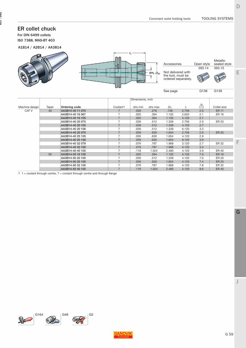
E
G 59
F
G
J
D
G
Coromant solid holding tools TOOLING SYSTEMS
RO
T -
EN
G
TOOLING SYSTEMS Coromant solid holding tools
ER collet chuckFor DIN 6499 colletsISO 7388, MAS-BT 403
A1B14 / A2B14 / AA3B14
Accessories Open styleMetallic sealed style
393.14 393.15Not delivered with the tool, must be ordered separately.
See page G138 G139
Dimensions, inch
Machine design Taper Ordering code Coolant1) dmt min dmt max D21 l1 V Collet sizeCAT V 40 AA3B14-40 11 070 7 .030 .276 .748 2.756 2.0 ER 11
AA3B14-40 16 067 7 .020 .394 1.102 2.620 2.1 ER 16AA3B14-40 16 105 7 .020 .394 1.102 4.120 2.7AA3B14-40 20 070 7 .039 .512 1.339 2.756 2.0 ER 20AA3B14-40 20 105 7 .039 .512 1.339 4.120 2.7AA3B14-40 20 156 7 .039 .512 1.339 6.120 3.3AA3B14-40 25 070 7 .059 .630 1.654 2.756 2.0 ER 25AA3B14-40 25 105 7 .059 .630 1.654 4.120 2.9AA3B14-40 25 156 7 .059 .630 1.654 6.120 3.9AA3B14-40 32 079 7 .079 .787 1.968 3.120 2.7 ER 32AA3B14-40 32 105 7 .079 .787 1.968 4.120 3.3AA3B14-40 40 105 7 .118 1.024 2.480 4.120 3.9 ER 40
50 AA3B14-50 16 105 7 .020 .394 1.102 4.120 7.0 ER 16AA3B14-50 20 105 7 .039 .512 1.339 4.120 7.0 ER 20AA3B14-50 25 105 7 .059 .630 1.654 4.120 7.4 ER 25AA3B14-50 32 105 7 .079 .787 1.968 4.120 7.8 ER 32AA3B14-50 40 105 7 .118 1.024 2.480 4.120 8.6 ER 40
1) 1 = coolant through centre, 7 = coolant through centre and through flange
G164 G48 G2
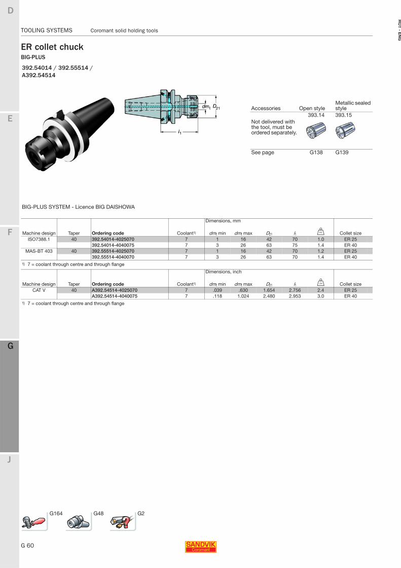
G 60
TOOLING SYSTEMS Coromant solid holding tools
E
F
G
J
D
G
RO
T - E
NG
TOOLING SYSTEMS Coromant solid holding tools
ER collet chuckBIG-PLUS
392.54014 / 392.55514 / A392.54514
Accessories Open styleMetallic sealed style
393.14 393.15Not delivered with the tool, must be ordered separately.
See page G138 G139
BIG-PLUS SYSTEM - Licence BIG DAISHOWA
Dimensions, mm
Machine design Taper Ordering code Coolant1) dmt min dmt max D21 l1 U Collet sizeISO7388.1 40 392.54014-4025070 7 1 16 42 70 1.0 ER 25
392.54014-4040075 7 3 26 63 75 1.4 ER 40MAS-BT 403 40 392.55514-4025070 7 1 16 42 70 1.2 ER 25
392.55514-4040070 7 3 26 63 70 1.4 ER 401) 7 = coolant through centre and through flange
Dimensions, inch
Machine design Taper Ordering code Coolant1) dmt min dmt max D21 l1 V Collet sizeCAT V 40 A392.54514-4025070 7 .039 .630 1.654 2.756 2.4 ER 25
A392.54514-4040075 7 .118 1.024 2.480 2.953 3.0 ER 401) 7 = coolant through centre and through flange
G164 G48 G2
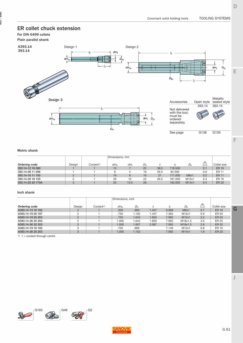
E
G 61
F
G
J
D
G
Coromant solid holding tools TOOLING SYSTEMS
RO
T -
EN
G
TOOLING SYSTEMS Coromant solid holding tools
ER collet chuck extensionFor DIN 6499 colletsPlain parallel shank
Metric shank
Inch shank
A393.14 Design 1 Design 2393.14
Accessories Open styleMetallic sealed style
393.14 393.15Not delivered with the tool, must be ordered separately.
See page G138 G139
Dimensions, mm
Ordering code Design Coolant1) dmm dmt D21 l1 l2 Dth U Collet size393.14-12 16 080 1 1 12 7 22 38.5 118.500 0.1 ER 16393.14-08 11 056 1 1 8 4 16 26.5 82.500 0.0 ER 11393.14-16 11 150 2 1 16 8 16 21 171.000 M8x1 0.2 ER 11393.14-20 16 155 2 1 20 12 22 26.5 181.500 M12x1 0.3 ER 16393.14-25 20 170A 3 1 25 13.5 28 182.000 M14x1 0.4 ER 20
Dimensions, inch
Ordering code Design Coolant1) dmm D21 l1 l2 Dth V Collet sizeA393.14-13 16 182 2 1 .500 .866 1.457 6.968 M6x1 0.7 ER 16A393.14-19 20 187 2 1 .750 1.102 1.457 7.362 M12x1 0.9 ER 20A393.14-19 25 203 2 1 .750 1.642 1.850 7.992 M12x1 2.2 ER 25A393.14-26 25 203 2 1 1.000 1.642 1.850 7.992 M18x1.5 3.5 ER 25A393.14-26 32 203 2 1 1.000 1.957 2.087 7.992 M18x1.5 2.6 ER 32A393.14-19 16 182 3 1 .750 .866 7.146 M12x1 0.8 ER 16A393.14-26 20 203 3 1 1.000 1.102 7.992 M14x1 1.8 ER 201) 1 = coolant through centre
G165 G48 G2
Design 3
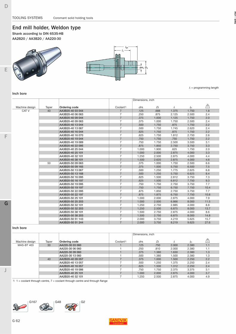
G 62
TOOLING SYSTEMS Coromant solid holding tools
E
F
G
J
D
G
RO
T - E
NG
TOOLING SYSTEMS Coromant solid holding tools
End mill holder, Weldon typeShank according to DIN 6535-HBAA2B20 / AA3B20 / AA220-30
Inch bore
Inch bore
l1 = programming length
Dimensions, inch
Machine design Taper Ordering code Coolant1) dmt D1 l1 l21 V
CAT V 40 AA3B20-40 03 044 7 .125 .688 1.375 1.750 1.8AA3B20-40 06 063 7 .250 .875 2.125 2.500 2.4AA3B20-40 09 044 7 .375 1.000 1.125 1.750 2.0AA3B20-40 09 063 7 .375 1.000 1.750 2.500 2.4AA3B20-40 13 044 7 .500 1.750 .875 1.750 2.2AA3B20-40 13 067 7 .500 1.750 1.745 2.620 2.4AA3B20-40 16 044 7 .625 1.750 .875 1.750 2.2AA3B20-40 16 070 7 .625 1.750 1.812 2.750 2.6AA3B20-40 19 044 7 .750 1.750 .750 1.750 2.2AA3B20-40 19 089 7 .750 1.750 2.500 3.500 3.1AA3B20-40 22 095 7 .875 1.850 2.750 3.750 3.3AA3B20-40 25 044 7 1.000 1.900 .625 1.750 2.0AA3B20-40 25 101 7 1.000 2.000 2.875 4.000 3.3AA3B20-40 32 101 7 1.250 2.500 2.875 4.000 4.4AA3B20-40 38 101 7 1.500 2.620 2.875 4.000 4.6
50 AA3B20-50 09 063 7 .375 1.000 1.750 2.500 6.6AA3B20-50 09 165 7 .375 1.000 5.750 6.500 7.5AA3B20-50 13 067 7 .500 1.250 1.775 2.625 6.8AA3B20-50 13 168 7 .500 1.250 5.750 6.625 8.4AA3B20-50 16 095 7 .625 1.500 2.812 3.750 7.3AA3B20-50 16 197 7 .625 1.500 6.812 7.750 9.3AA3B20-50 19 095 7 .750 1.750 2.750 3.750 7.7AA3B20-50 19 197 7 .750 1.750 6.750 7.750 10.4AA3B20-50 22 095 7 .875 1.850 2.750 3.750 7.7AA3B20-50 22 197 7 .875 1.875 6.750 7.750 10.8AA3B20-50 25 101 7 1.000 2.000 2.875 4.000 7.9AA3B20-50 25 203 7 1.000 2.000 6.866 8.000 11.5AA3B20-50 32 101 7 1.250 2.750 2.885 4.000 8.8AA3B20-50 32 203 7 1.250 2.500 6.875 8.000 13.7AA3B20-50 38 101 7 1.500 2.750 2.875 4.000 8.6AA3B20-50 38 203 7 1.500 2.750 6.875 8.000 14.8AA3B20-50 51 143 7 2.000 3.750 4.219 5.625 15.7AA3B20-50 51 244 7 2.000 3.750 8.219 9.625 27.6
Dimensions, inch
Machine design Taper Ordering code Coolant1) dmt D1 l1 l21 V
MAS-BT 403 30 AA220-30 03 060 1 .125 .750 2.000 2.380 1.1AA220-30 06 060 1 .250 .810 2.000 2.380 1.1AA220-30 09 060 1 .375 1.380 1.630 2.380 1.3AA220-30 13 060 1 .500 1.380 1.500 2.380 1.3
40 AA2B20-40 09 057 7 .375 1.000 1.500 2.250 2.2AA2B20-40 13 057 7 .500 1.250 1.375 2.250 2.4AA2B20-40 16 057 7 .625 1.500 1.312 2.250 2.4AA2B20-40 19 086 7 .750 1.750 2.375 3.375 3.1AA2B20-40 25 101 7 1.000 2.000 2.875 4.000 3.7AA2B20-40 32 101 7 1.250 2.500 2.875 4.000 4.9
1) 1 = coolant through centre, 7 = coolant through centre and through flange
G167 G48 G2
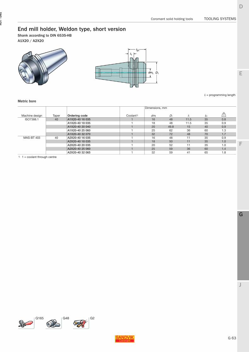
E
G 63
F
G
J
D
G
Coromant solid holding tools TOOLING SYSTEMS
RO
T -
EN
G
TOOLING SYSTEMS Coromant solid holding tools
End mill holder, Weldon type, short versionShank according to DIN 6535-HBA1X20 / A2X20
Metric bore
l1 = programming length
Dimensions, mm
Machine design Taper Ordering code Coolant1) dmt D1 l1 l21 U
ISO7388.1 40 A1X20-40 16 035 1 16 48 11.5 35 0.8A1X20-40 18 035 1 18 48 11.5 35 0.9A1X20-40 20 040 1 20 49.8 15 40 0.9A1X20-40 25 060 1 25 62 36 60 1.3A1X20-40 32 070 1 32 72 48 70 1.7
MAS-BT 403 40 A2X20-40 16 035 1 16 48 11 35 0.9A2X20-40 18 035 1 18 50 11 35 1.0A2X20-40 20 035 1 20 52 11 35 1.0A2X20-40 25 060 1 25 59 36 60 1.4A2X20-40 32 065 1 32 59 41 65 1.8
1) 1 = coolant through centre
G165 G48 G2
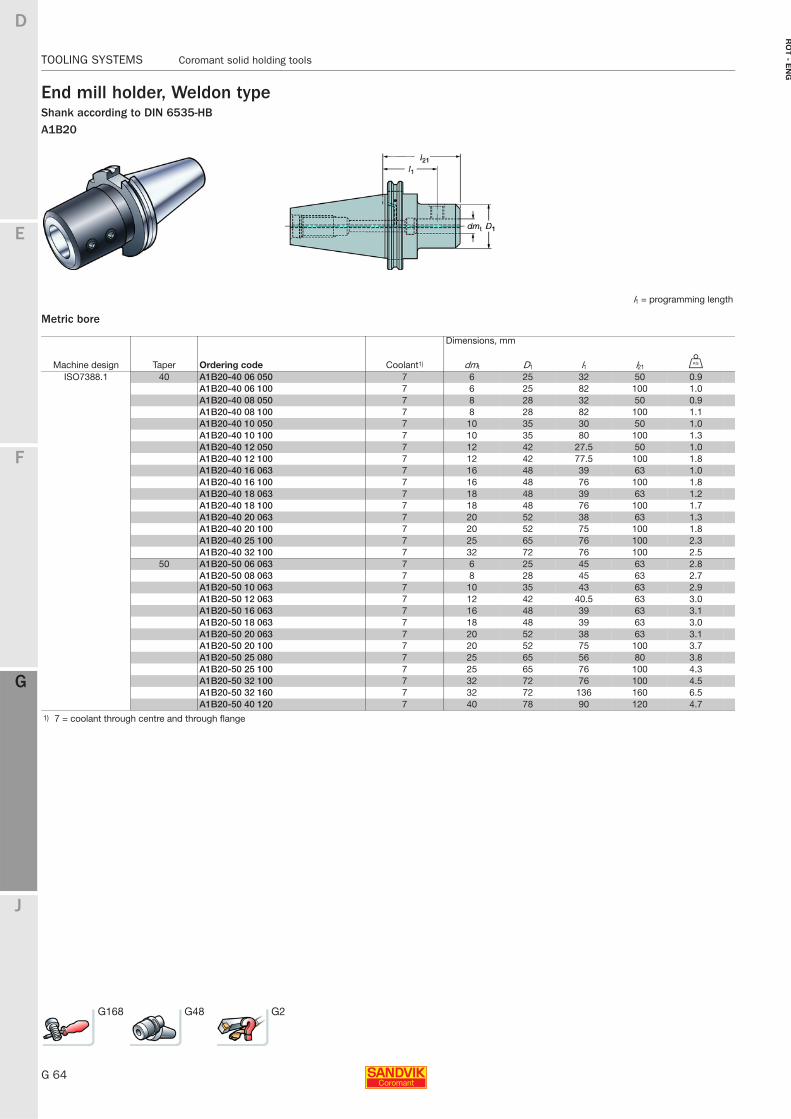
G 64
TOOLING SYSTEMS Coromant solid holding tools
E
F
G
J
D
G
RO
T - E
NG
TOOLING SYSTEMS Coromant solid holding tools
End mill holder, Weldon typeShank according to DIN 6535-HBA1B20
Metric bore
l1 = programming length
Dimensions, mm
Machine design Taper Ordering code Coolant1) dmt D1 l1 l21 U
ISO7388.1 40 A1B20-40 06 050 7 6 25 32 50 0.9A1B20-40 06 100 7 6 25 82 100 1.0A1B20-40 08 050 7 8 28 32 50 0.9A1B20-40 08 100 7 8 28 82 100 1.1A1B20-40 10 050 7 10 35 30 50 1.0A1B20-40 10 100 7 10 35 80 100 1.3A1B20-40 12 050 7 12 42 27.5 50 1.0A1B20-40 12 100 7 12 42 77.5 100 1.8A1B20-40 16 063 7 16 48 39 63 1.0A1B20-40 16 100 7 16 48 76 100 1.8A1B20-40 18 063 7 18 48 39 63 1.2A1B20-40 18 100 7 18 48 76 100 1.7A1B20-40 20 063 7 20 52 38 63 1.3A1B20-40 20 100 7 20 52 75 100 1.8A1B20-40 25 100 7 25 65 76 100 2.3A1B20-40 32 100 7 32 72 76 100 2.5
50 A1B20-50 06 063 7 6 25 45 63 2.8A1B20-50 08 063 7 8 28 45 63 2.7A1B20-50 10 063 7 10 35 43 63 2.9A1B20-50 12 063 7 12 42 40.5 63 3.0A1B20-50 16 063 7 16 48 39 63 3.1A1B20-50 18 063 7 18 48 39 63 3.0A1B20-50 20 063 7 20 52 38 63 3.1A1B20-50 20 100 7 20 52 75 100 3.7A1B20-50 25 080 7 25 65 56 80 3.8A1B20-50 25 100 7 25 65 76 100 4.3A1B20-50 32 100 7 32 72 76 100 4.5A1B20-50 32 160 7 32 72 136 160 6.5A1B20-50 40 120 7 40 78 90 120 4.7
1) 7 = coolant through centre and through flange
G168 G48 G2
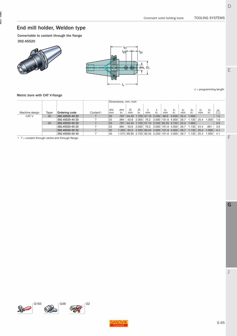
E
G 65
F
G
J
D
G
Coromant solid holding tools TOOLING SYSTEMS
RO
T -
EN
G
TOOLING SYSTEMS Coromant solid holding tools
End mill holder, Weldon type
Metric bore with CAT V-flange
Convertable to coolant through the flange
392.45520
l1 = programming length
Dimensions, mm, inch
Machine design Taper Ordering code Coolant1)dmtmm
dmtin.
D1mm
D1in.
lcmm
lcin.
l21 mm
l21 in.
l22mm
l22in.
l23mm
l23in. U
CAT V 40 392.45520-40 20 7 20 .787 44.45 1.750 57.15 2.250 88.9 3.500 25.4 1.000 1.5392.45520-40 25 7 25 .984 50.8 2.000 76.2 3.000 101.6 4.000 28.7 1.130 25.4 1.000 1.6
50 392.45520-50 20 7 20 .787 44.45 1.750 57.15 2.250 95.25 3.750 25.4 1.000 3.5392.45520-50 25 7 25 .984 50.8 2.000 76.2 3.000 101.6 4.000 28.7 1.130 24.4 .961 3.8392.45520-50 32 7 32 1.260 63.5 2.500 66.04 2.600 101.6 4.000 28.7 1.130 25.4 1.000 4.1392.45520-50 40 7 40 1.575 69.85 2.750 82.55 3.250 101.6 4.000 28.7 1.130 25.4 1.000 4.1
1) 7 = coolant through centre and through flange
G165 G48 G2
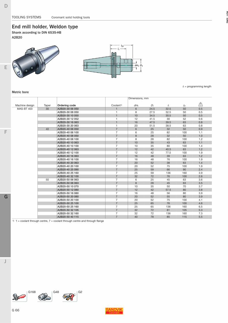
G 66
TOOLING SYSTEMS Coromant solid holding tools
E
F
G
J
D
G
RO
T - E
NG
TOOLING SYSTEMS Coromant solid holding tools
End mill holder, Weldon typeShank according to DIN 6535-HBA2B20
Metric bore
l1 = programming length
Dimensions, mm
Machine design Taper Ordering code Coolant1) dmt D1 l1 l21 U
MAS-BT 403 30 A2B20-30 06 050 1 6 24.5 32.5 50 0.5A2B20-30 08 050 1 8 27.5 32.5 50 0.5A2B20-30 10 050 1 10 34.5 30.5 50 0.5A2B20-30 12 052 1 12 41.5 30 52 0.6A2B20-30 16 063 1 16 47.5 39.5 63 0.8A2B20-30 20 063 1 20 51.5 38.5 63 0.8
40 A2B20-40 06 050 7 6 25 32 50 0.9A2B20-40 06 100 7 6 25 82 100 1.1A2B20-40 08 050 7 8 28 32 50 1.0A2B20-40 08 100 7 8 28 82 100 1.2A2B20-40 10 063 7 10 35 43 63 1.1A2B20-40 10 100 7 10 35 80 100 1.4A2B20-40 12 063 7 12 42 40.5 63 1.2A2B20-40 12 100 7 12 42 77.5 100 1.9A2B20-40 16 063 7 16 48 39 63 1.2A2B20-40 16 100 7 16 48 76 100 1.9A2B20-40 20 063 7 20 52 38 63 1.4A2B20-40 20 100 7 20 52 75 100 1.9A2B20-40 25 090 7 25 59 66 90 2.4A2B20-40 25 160 7 25 59 136 160 3.9A2B20-40 32 100 7 32 72 76 100 2.6
50 A2B20-50 06 063 7 6 25 45 63 3.6A2B20-50 08 063 7 8 28 45 63 3.5A2B20-50 10 070 7 10 35 50 70 3.7A2B20-50 12 080 7 12 42 57.5 80 3.8A2B20-50 16 080 7 16 48 56 80 3.9A2B20-50 20 080 7 20 52 55 80 3.9A2B20-50 20 100 7 20 52 75 100 4.1A2B20-50 25 100 7 25 65 76 100 4.6A2B20-50 25 160 7 25 65 136 160 6.5A2B20-50 32 105 7 32 72 81 105 5.3A2B20-50 32 160 7 32 72 136 160 7.3A2B20-50 40 115 7 40 78 85 115 5.5
1) 1 = coolant through centre, 7 = coolant through centre and through flange
G168 G48 G2
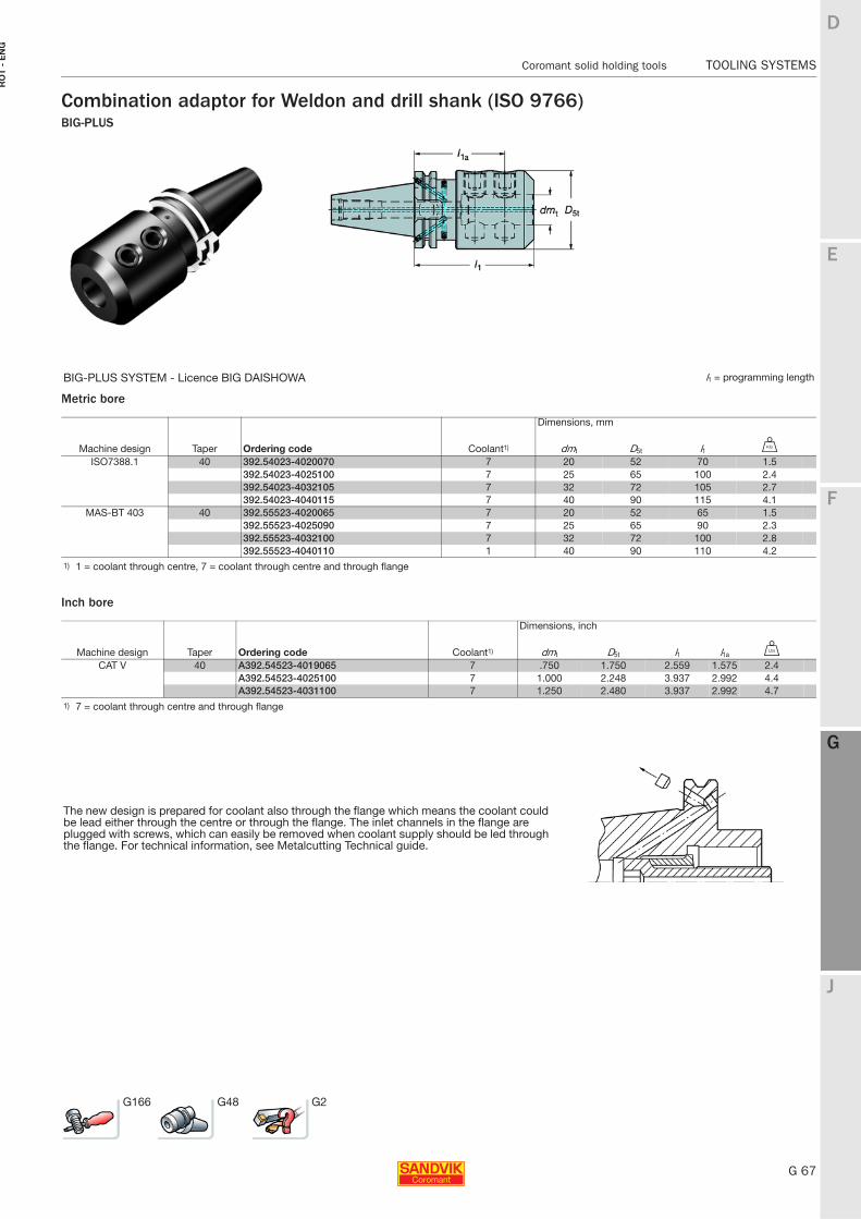
E
G 67
F
G
J
D
G
Coromant solid holding tools TOOLING SYSTEMS
RO
T -
EN
G
TOOLING SYSTEMS Coromant solid holding tools
Combination adaptor for Weldon and drill shank (ISO 9766)BIG-PLUS
Metric bore
Inch bore
BIG-PLUS SYSTEM - Licence BIG DAISHOWA l1 = programming length
Dimensions, mm
Machine design Taper Ordering code Coolant1) dmt D5t l1 U
ISO7388.1 40 392.54023-4020070 7 20 52 70 1.5392.54023-4025100 7 25 65 100 2.4392.54023-4032105 7 32 72 105 2.7392.54023-4040115 7 40 90 115 4.1
MAS-BT 403 40 392.55523-4020065 7 20 52 65 1.5392.55523-4025090 7 25 65 90 2.3392.55523-4032100 7 32 72 100 2.8392.55523-4040110 1 40 90 110 4.2
1) 1 = coolant through centre, 7 = coolant through centre and through flange
Dimensions, inch
Machine design Taper Ordering code Coolant1) dmt D5t l1 l1a V
CAT V 40 A392.54523-4019065 7 .750 1.750 2.559 1.575 2.4A392.54523-4025100 7 1.000 2.248 3.937 2.992 4.4A392.54523-4031100 7 1.250 2.480 3.937 2.992 4.7
1) 7 = coolant through centre and through flange
The new design is prepared for coolant also through the flange which means the coolant could be lead either through the centre or through the flange. The inlet channels in the flange are plugged with screws, which can easily be removed when coolant supply should be led through the flange. For technical information, see Metalcutting Technical guide.
G166 G48 G2
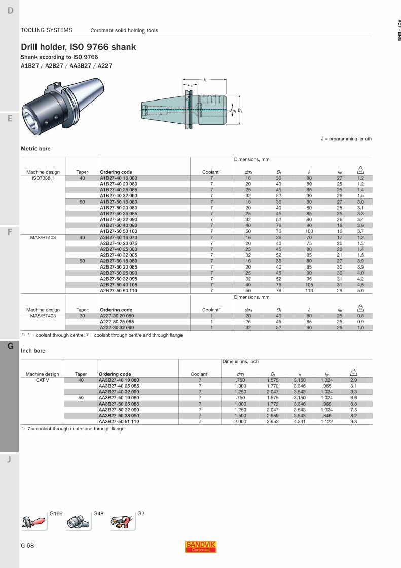
G 68
TOOLING SYSTEMS Coromant solid holding tools
E
F
G
J
D
G
RO
T - E
NG
TOOLING SYSTEMS Coromant solid holding tools
Drill holder, ISO 9766 shankShank according to ISO 9766A1B27 / A2B27 / AA3B27 / A227
Metric bore
Inch bore
l1 = programming length
Dimensions, mm
Machine design Taper Ordering code Coolant1) dmt D1 l1 l1b U
ISO7388.1 40 A1B27-40 16 080 7 16 36 80 27 1.2A1B27-40 20 080 7 20 40 80 25 1.2A1B27-40 25 085 7 25 45 85 25 1.4A1B27-40 32 090 7 32 52 90 26 1.5
50 A1B27-50 16 080 7 16 36 80 27 3.0A1B27-50 20 080 7 20 40 80 25 3.1A1B27-50 25 085 7 25 45 85 25 3.3A1B27-50 32 090 7 32 52 90 26 3.4A1B27-50 40 090 7 40 76 90 16 3.9A1B27-50 50 100 7 50 76 100 16 3.7
MAS/BT403 40 A2B27-40 16 070 7 16 36 70 17 1.2A2B27-40 20 075 7 20 40 75 20 1.3A2B27-40 25 080 7 25 45 80 20 1.4A2B27-40 32 085 7 32 52 85 21 1.5
50 A2B27-50 16 080 7 16 36 80 27 3.9A2B27-50 20 085 7 20 40 85 30 3.9A2B27-50 25 090 7 25 45 90 30 4.0A2B27-50 32 095 7 32 52 95 31 4.2A2B27-50 40 105 7 40 76 105 31 4.5A2B27-50 50 113 7 50 76 113 29 5.0
Dimensions, mm
Machine design Taper Ordering code Coolant1) dmt D1 l1 l1b U
MAS/BT403 30 A227-30 20 080 1 20 40 80 25 0.8A227-30 25 085 1 25 45 85 25 0.9A227-30 32 090 1 32 52 90 26 1.0
1) 1 = coolant through centre, 7 = coolant through centre and through flange
Dimensions, inch
Machine design Taper Ordering code Coolant1) dmt D1 l1 l1b V
CAT V 40 AA3B27-40 19 080 7 .750 1.575 3.150 1.024 2.9AA3B27-40 25 085 7 1.000 1.772 3.346 .965 3.1AA3B27-40 32 090 7 1.250 2.047 3.543 1.024 3.3
50 AA3B27-50 19 080 7 .750 1.575 3.150 1.024 6.6AA3B27-50 25 085 7 1.000 1.772 3.346 .965 6.8AA3B27-50 32 090 7 1.250 2.047 3.543 1.024 7.3AA3B27-50 38 090 7 1.500 2.559 3.543 .846 8.2AA3B27-50 51 110 7 2.000 2.953 4.331 1.122 9.3
1) 7 = coolant through centre and through flange
G169 G48 G2
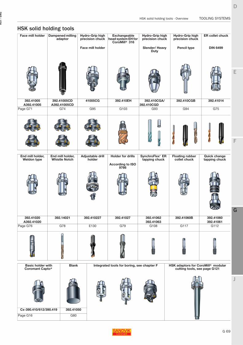
E
G 69
F
G
J
D
G
HSK solid holding tools - Overview TOOLING SYSTEMS
RO
T -
EN
G
TOOLING SYSTEMS HSK solid holding tools - Overview
HSK solid holding toolsFace mill holder Dampened milling
adaptorHydro-Grip high precision chuck
Exchangeable head system EH for
CoroMill® 316
Hydro-Grip high precision chuck
Hydro-Grip high precision chuck
ER collet chuck
Face mill holder Slender/ Heavy Duty
Pencil type DIN 6499
392.41005 392.41005CD 41005CG 392.410EH 392.410CGA/ 392.410CGB 392.41014A392.41005 A392.41005CD 392.410CGD
Page G71 G74 G95 G103 G93 G94 G75
End mill holder, Weldon type
End mill holder, Whistle Notch
Adjustable drill holder
Holder for drills SynchroFlex® ER tapping chuck
Floating rubber collet chuck
Quick change tapping chuck
According to ISO 9766
392.41020 392.14021 392.410227 392.41027 392.41062 392.41060B 392.41060A392.41020 392.41063 392.41061
Page G76 G78 E130 G79 G108 G117 G112
Basic holder with Coromant Capto®
Blank Integrated tools for boring, see chapter F HSK adaptors for CoroMill® modular cutting tools, see page G121
Cx-390.410/612/390.419 392.41050
Page G16 G80
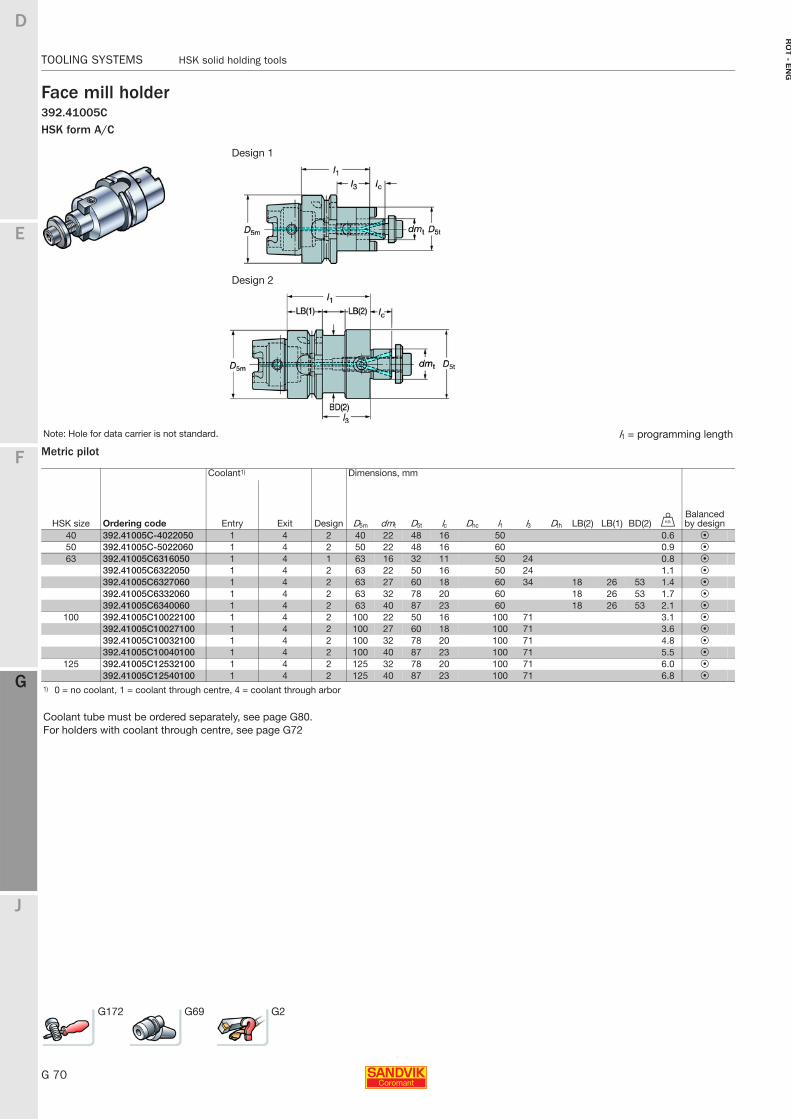
G 70
TOOLING SYSTEMS HSK solid holding tools
E
F
G
J
D
G
RO
T - E
NG
TOOLING SYSTEMS HSK solid holding tools
Face mill holder392.41005CHSK form A/C
Metric pilot
Design 1
Design 2
Note: Hole for data carrier is not standard. l1 = programming length
Coolant1) Dimensions, mm
HSK size Ordering code Entry Exit Design D5m dmt D5t lc Dhc l1 l3 Dth LB(2) LB(1) BD(2) UBalanced by design
40 392.41005C-4022050 1 4 2 40 22 48 16 50 0.6 P50 392.41005C-5022060 1 4 2 50 22 48 16 60 0.9 P63 392.41005C6316050 1 4 1 63 16 32 11 50 24 0.8 P
392.41005C6322050 1 4 2 63 22 50 16 50 24 1.1 P392.41005C6327060 1 4 2 63 27 60 18 60 34 18 26 53 1.4 P392.41005C6332060 1 4 2 63 32 78 20 60 18 26 53 1.7 P392.41005C6340060 1 4 2 63 40 87 23 60 18 26 53 2.1 P
100 392.41005C10022100 1 4 2 100 22 50 16 100 71 3.1 P392.41005C10027100 1 4 2 100 27 60 18 100 71 3.6 P392.41005C10032100 1 4 2 100 32 78 20 100 71 4.8 P392.41005C10040100 1 4 2 100 40 87 23 100 71 5.5 P
125 392.41005C12532100 1 4 2 125 32 78 20 100 71 6.0 P392.41005C12540100 1 4 2 125 40 87 23 100 71 6.8 P
1) 0 = no coolant, 1 = coolant through centre, 4 = coolant through arbor
Coolant tube must be ordered separately, see page G80.For holders with coolant through centre, see page G72
G172 G69 G2
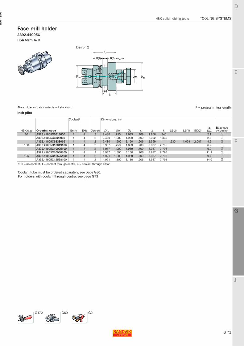
E
G 71
F
G
J
D
G
HSK solid holding tools TOOLING SYSTEMS
RO
T -
EN
G
TOOLING SYSTEMS HSK solid holding tools
Face mill holderA392.41005CHSK form A/C
Inch pilot
Design 2
Note: Hole for data carrier is not standard. l1 = programming length
Coolant1) Dimensions, inch
HSK size Ordering code Entry Exit Design D5m dmt D5t lc l1 l3 LB(2) LB(1) BD(2) VBalanced by design
63 A392.41005C6319050 1 4 2 2.480 .750 1.693 .709 1.968 .945 2.1 PA392.41005C6325060 1 4 2 2.480 1.000 1.969 .709 2.362 1.339 2.8 PA392.41005C6338065 1 4 2 2.480 1.500 3.150 .906 2.559 .630 1.024 2.087 4.6 P
100 A392.41005C10019100 1 4 2 3.937 .750 1.693 .709 3.937 2.795 6.2 PA392.41005C10025100 1 4 2 3.937 1.000 1.969 .709 3.937 2.795 6.9 PA392.41005C10038100 1 4 2 3.937 1.500 3.150 .906 3.937 2.795 11.1 P
125 A392.41005C12525100 1 4 2 4.921 1.000 1.969 .709 3.937 2.795 9.7 PA392.41005C12538100 1 4 2 4.921 1.500 3.150 .906 3.937 2.795 14.0 P
1) 0 = no coolant, 1 = coolant through centre, 4 = coolant through arbor
Coolant tube must be ordered separately, see page G80.For holders with coolant through centre, see page G73
G172 G69 G2
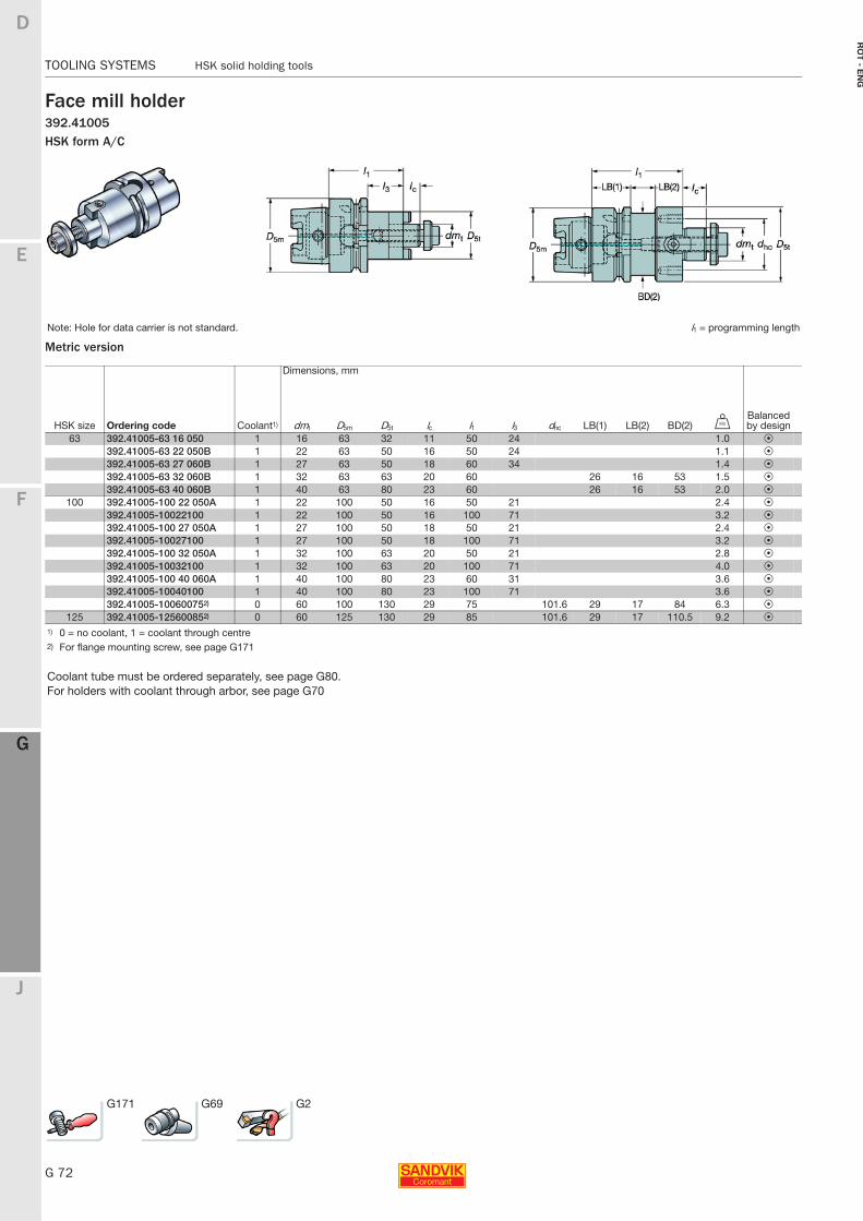
G 72
TOOLING SYSTEMS HSK solid holding tools
E
F
G
J
D
G
RO
T - E
NG
TOOLING SYSTEMS HSK solid holding tools
Face mill holder392.41005HSK form A/C
Metric version
Note: Hole for data carrier is not standard. l1 = programming length
Dimensions, mm
HSK size Ordering code Coolant1) dmt D5m D5t lc l1 l3 dhc LB(1) LB(2) BD(2) UBalanced by design
63 392.41005-63 16 050 1 16 63 32 11 50 24 1.0 P392.41005-63 22 050B 1 22 63 50 16 50 24 1.1 P392.41005-63 27 060B 1 27 63 50 18 60 34 1.4 P392.41005-63 32 060B 1 32 63 63 20 60 26 16 53 1.5 P392.41005-63 40 060B 1 40 63 80 23 60 26 16 53 2.0 P
100 392.41005-100 22 050A 1 22 100 50 16 50 21 2.4 P392.41005-10022100 1 22 100 50 16 100 71 3.2 P392.41005-100 27 050A 1 27 100 50 18 50 21 2.4 P392.41005-10027100 1 27 100 50 18 100 71 3.2 P392.41005-100 32 050A 1 32 100 63 20 50 21 2.8 P392.41005-10032100 1 32 100 63 20 100 71 4.0 P392.41005-100 40 060A 1 40 100 80 23 60 31 3.6 P392.41005-10040100 1 40 100 80 23 100 71 3.6 P392.41005-100600752) 0 60 100 130 29 75 101.6 29 17 84 6.3 P
125 392.41005-125600852) 0 60 125 130 29 85 101.6 29 17 110.5 9.2 P
1) 0 = no coolant, 1 = coolant through centre2) For flange mounting screw, see page G171
Coolant tube must be ordered separately, see page G80.For holders with coolant through arbor, see page G70
G171 G69 G2
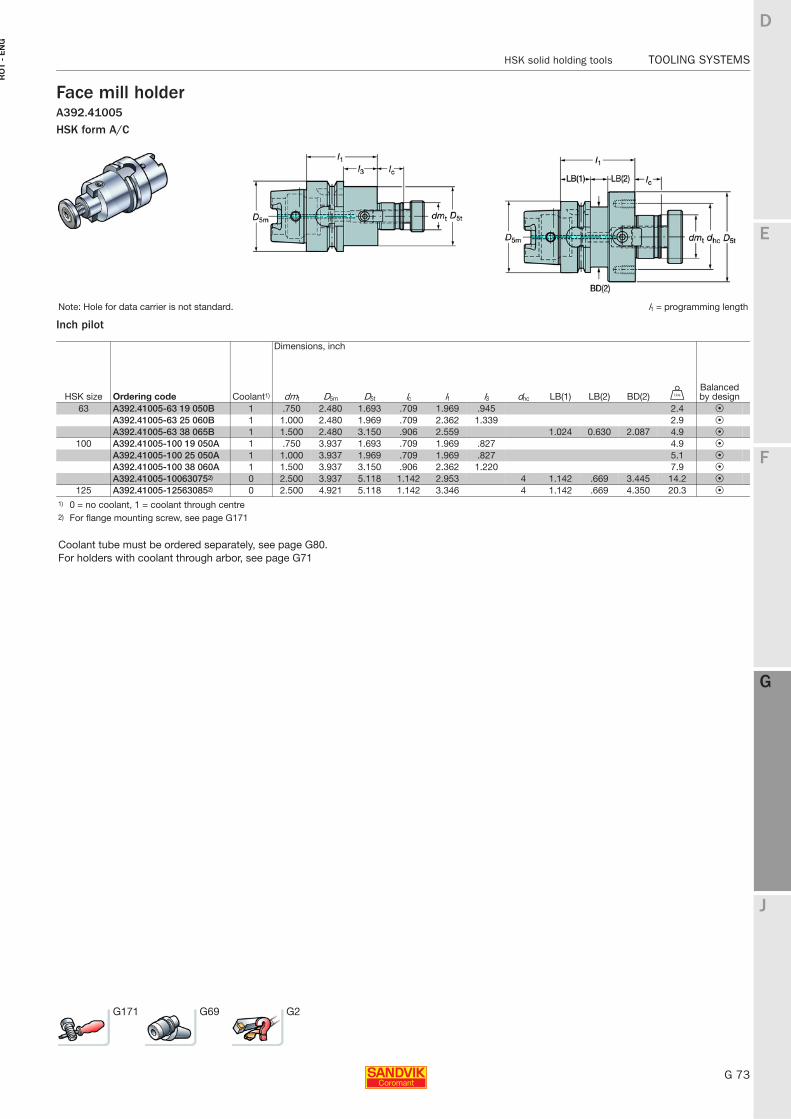
E
G 73
F
G
J
D
G
HSK solid holding tools TOOLING SYSTEMS
RO
T -
EN
G
TOOLING SYSTEMS HSK solid holding tools
Face mill holderA392.41005HSK form A/C
Inch pilot
Note: Hole for data carrier is not standard. l1 = programming length
Dimensions, inch
HSK size Ordering code Coolant1) dmt D5m D5t lc l1 l3 dhc LB(1) LB(2) BD(2) VBalanced by design
63 A392.41005-63 19 050B 1 .750 2.480 1.693 .709 1.969 .945 2.4 PA392.41005-63 25 060B 1 1.000 2.480 1.969 .709 2.362 1.339 2.9 PA392.41005-63 38 065B 1 1.500 2.480 3.150 .906 2.559 1.024 0.630 2.087 4.9 P
100 A392.41005-100 19 050A 1 .750 3.937 1.693 .709 1.969 .827 4.9 PA392.41005-100 25 050A 1 1.000 3.937 1.969 .709 1.969 .827 5.1 PA392.41005-100 38 060A 1 1.500 3.937 3.150 .906 2.362 1.220 7.9 PA392.41005-100630752) 0 2.500 3.937 5.118 1.142 2.953 4 1.142 .669 3.445 14.2 P
125 A392.41005-125630852) 0 2.500 4.921 5.118 1.142 3.346 4 1.142 .669 4.350 20.3 P
1) 0 = no coolant, 1 = coolant through centre2) For flange mounting screw, see page G171
Coolant tube must be ordered separately, see page G80.For holders with coolant through arbor, see page G71
G171 G69 G2
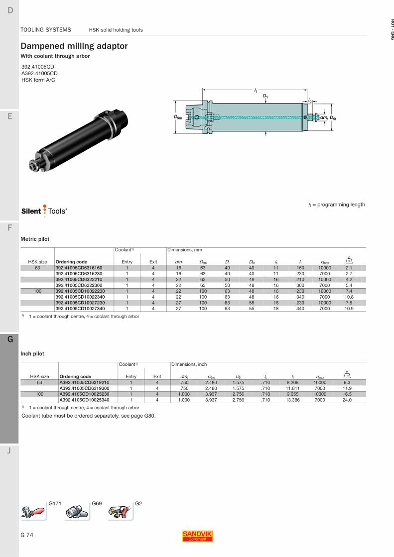
G 74
TOOLING SYSTEMS HSK solid holding tools
E
F
G
J
D
G
RO
T - E
NG
TOOLING SYSTEMS HSK solid holding tools
Dampened milling adaptorWith coolant through arbor
Metric pilot
Inch pilot
392.41005CDA392.41005CDHSK form A/C
l1 = programming length
Coolant1) Dimensions, mm
HSK size Ordering code Entry Exit dmt D5m D1 D5t lc l1 nmax U
63 392.41005CD6316160 1 4 16 63 40 40 11 160 10000 2.1392.41005CD6316230 1 4 16 63 40 40 11 230 7000 2.7392.41005CD6322210 1 4 22 63 50 48 16 210 10000 4.2392.41005CD6322300 1 4 22 63 50 48 16 300 7000 5.4
100 392.41005CD10022230 1 4 22 100 63 48 16 230 10000 7.4392.41005CD10022340 1 4 22 100 63 48 16 340 7000 10.8392.41005CD10027230 1 4 27 100 63 55 18 230 10000 7.5392.41005CD10027340 1 4 27 100 63 55 18 340 7000 10.9
1) 1 = coolant through centre, 4 = coolant through arbor
Coolant1) Dimensions, inch
HSK size Ordering code Entry Exit dmt D5m D5t lc l1 nmax V
63 A392.41005CD6319210 1 4 .750 2.480 1.575 .710 8.268 10000 9.3A392.41005CD6319300 1 4 .750 2.480 1.575 .710 11.811 7000 11.9
100 A392.4105CD10025230 1 4 1.000 3.937 2.756 .710 9.055 10000 16.5A392.4105CD10025340 1 4 1.000 3.937 2.756 .710 13.386 7000 24.0
1) 1 = coolant through centre, 4 = coolant through arbor
Coolant tube must be ordered separately, see page G80.
G171 G69 G2
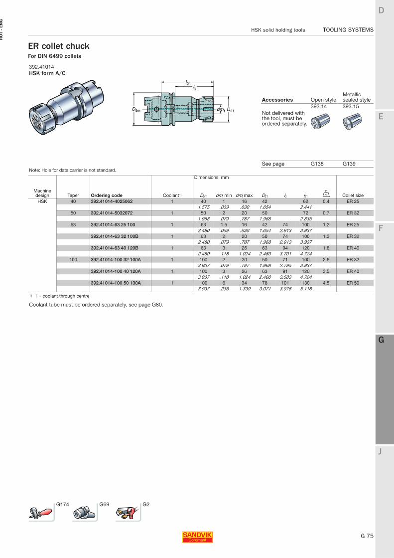
E
G 75
F
G
J
D
G
HSK solid holding tools TOOLING SYSTEMS
RO
T -
EN
G
TOOLING SYSTEMS HSK solid holding tools
ER collet chuckFor DIN 6499 collets
392.41014HSK form A/C
Accessories Open styleMetallic sealed style
393.14 393.15 Not delivered with the tool, must be ordered separately.
See page G138 G139Note: Hole for data carrier is not standard.
Dimensions, mm
Machine design Taper Ordering code Coolant1) D5m dmt min dmt max D21 l3 l21 U Collet sizeHSK 40 392.41014-4025062 1 40 1 16 42 62 0.4 ER 25
1.575 .039 .630 1.654 2.44150 392.41014-5032072 1 50 2 20 50 72 0.7 ER 32
1.968 .079 .787 1.968 2.83563 392.41014-63 25 100 1 63 1.5 16 42 74 100 1.2 ER 25
2.480 .059 .630 1.654 2.913 3.937392.41014-63 32 100B 1 63 2 20 50 74 100 1.2 ER 32
2.480 .079 .787 1.968 2.913 3.937392.41014-63 40 120B 1 63 3 26 63 94 120 1.8 ER 40
2.480 .118 1.024 2.480 3.701 4.724100 392.41014-100 32 100A 1 100 2 20 50 71 100 2.6 ER 32
3.937 .079 .787 1.968 2.795 3.937392.41014-100 40 120A 1 100 3 26 63 91 120 3.5 ER 40
3.937 .118 1.024 2.480 3.583 4.724392.41014-100 50 130A 1 100 6 34 78 101 130 4.5 ER 50
3.937 .236 1.339 3.071 3.976 5.1181) 1 = coolant through centre
Coolant tube must be ordered separately, see page G80.
G174 G69 G2
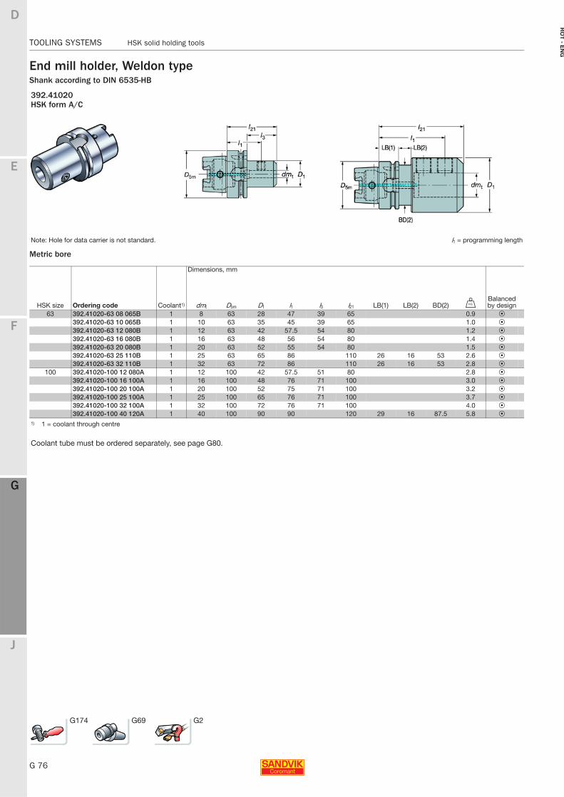
G 76
TOOLING SYSTEMS HSK solid holding tools
E
F
G
J
D
G
RO
T - E
NG
TOOLING SYSTEMS HSK solid holding tools
End mill holder, Weldon typeShank according to DIN 6535-HB
Metric bore
392.41020HSK form A/C
Note: Hole for data carrier is not standard. l1 = programming length
Dimensions, mm
HSK size Ordering code Coolant1) dmt D5m D1 l1 l3 l21 LB(1) LB(2) BD(2) UBalanced by design
63 392.41020-63 08 065B 1 8 63 28 47 39 65 0.9 P392.41020-63 10 065B 1 10 63 35 45 39 65 1.0 P392.41020-63 12 080B 1 12 63 42 57.5 54 80 1.2 P392.41020-63 16 080B 1 16 63 48 56 54 80 1.4 P392.41020-63 20 080B 1 20 63 52 55 54 80 1.5 P392.41020-63 25 110B 1 25 63 65 86 110 26 16 53 2.6 P392.41020-63 32 110B 1 32 63 72 86 110 26 16 53 2.8 P
100 392.41020-100 12 080A 1 12 100 42 57.5 51 80 2.8 P392.41020-100 16 100A 1 16 100 48 76 71 100 3.0 P392.41020-100 20 100A 1 20 100 52 75 71 100 3.2 P392.41020-100 25 100A 1 25 100 65 76 71 100 3.7 P392.41020-100 32 100A 1 32 100 72 76 71 100 4.0 P392.41020-100 40 120A 1 40 100 90 90 120 29 16 87.5 5.8 P
1) 1 = coolant through centre
Coolant tube must be ordered separately, see page G80.
G174 G69 G2
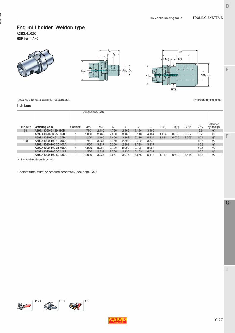
E
G 77
F
G
J
D
G
HSK solid holding tools TOOLING SYSTEMS
RO
T -
EN
G
TOOLING SYSTEMS HSK solid holding tools
End mill holder, Weldon typeA392.41020HSK form A/C
Inch bore
Note: Hole for data carrier is not standard. l1 = programming length
Dimensions, inch
HSK size Ordering code Coolant1) dmt D5m D1 l1 l3 l21 LB(1) LB(2) BD(2) VBalanced by design
63 A392.41020-63 19 080B 1 .750 2.480 1.750 2.165 2.126 3.150 6.6 PA392.41020-63 25 105B 1 1.000 2.480 2.250 3.189 3.110 4.134 1.024 0.630 2.087 9.7 PA392.41020-63 31 105B 1 1.250 2.480 2.480 3.189 3.110 4.134 1.024 0.630 2.087 10.1 P
100 A392.41020-100 19 090A 1 .750 3.937 1.750 2.598 2.402 3.543 12.6 PA392.41020-100 25 100A 1 1.000 3.937 2.250 2.992 2.795 3.937 15.2 PA392.41020-100 31 100A 1 1.250 3.937 2.480 2.992 2.795 3.937 16.1 PA392.41020-100 38 110A 1 1.500 3.937 2.756 3.150 3.189 4.331 18.5 PA392.41020-100 50 130A 1 2.000 3.937 3.661 3.976 3.976 5.118 1.142 0.630 3.445 12.8 P
1) 1 = coolant through centre
Coolant tube must be ordered separately, see page G80.
G174 G69 G2
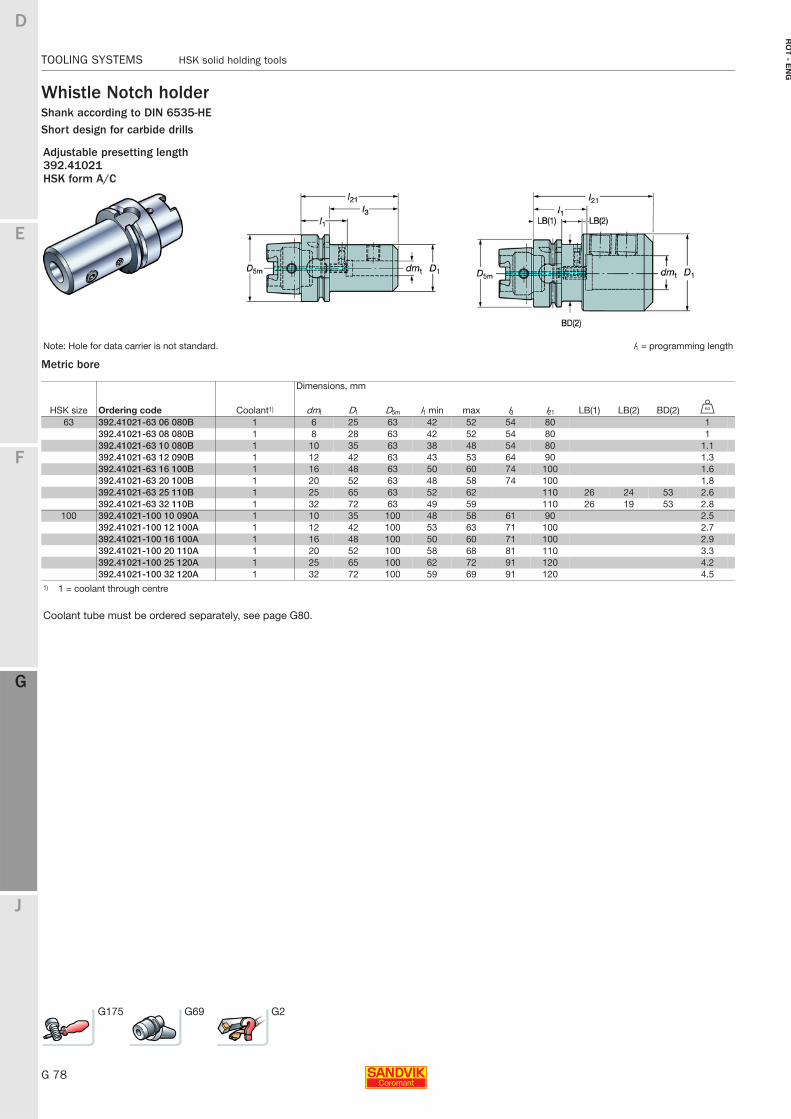
G 78
TOOLING SYSTEMS HSK solid holding tools
E
F
G
J
D
G
RO
T - E
NG
TOOLING SYSTEMS HSK solid holding tools
Whistle Notch holderShank according to DIN 6535-HEShort design for carbide drills
Metric bore
Adjustable presetting length392.41021HSK form A/C
Note: Hole for data carrier is not standard. l1 = programming length
Dimensions, mm
HSK size Ordering code Coolant1) dmt D1 D5m l1 min max l3 l21 LB(1) LB(2) BD(2) U
63 392.41021-63 06 080B 1 6 25 63 42 52 54 80 1392.41021-63 08 080B 1 8 28 63 42 52 54 80 1392.41021-63 10 080B 1 10 35 63 38 48 54 80 1.1392.41021-63 12 090B 1 12 42 63 43 53 64 90 1.3392.41021-63 16 100B 1 16 48 63 50 60 74 100 1.6392.41021-63 20 100B 1 20 52 63 48 58 74 100 1.8392.41021-63 25 110B 1 25 65 63 52 62 110 26 24 53 2.6392.41021-63 32 110B 1 32 72 63 49 59 110 26 19 53 2.8
100 392.41021-100 10 090A 1 10 35 100 48 58 61 90 2.5392.41021-100 12 100A 1 12 42 100 53 63 71 100 2.7392.41021-100 16 100A 1 16 48 100 50 60 71 100 2.9392.41021-100 20 110A 1 20 52 100 58 68 81 110 3.3392.41021-100 25 120A 1 25 65 100 62 72 91 120 4.2392.41021-100 32 120A 1 32 72 100 59 69 91 120 4.5
1) 1 = coolant through centre
Coolant tube must be ordered separately, see page G80.
G175 G69 G2
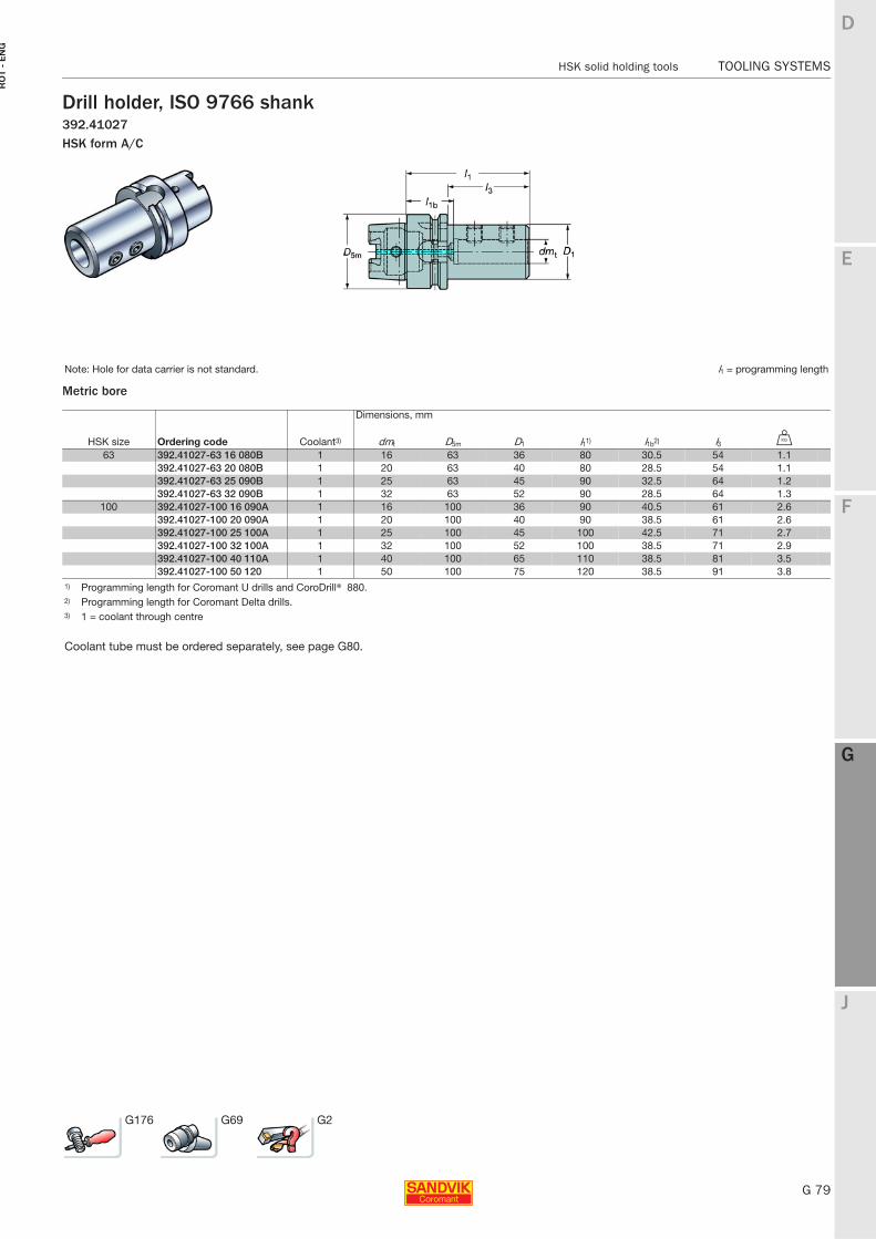
E
G 79
F
G
J
D
G
HSK solid holding tools TOOLING SYSTEMS
RO
T -
EN
G
TOOLING SYSTEMS HSK solid holding tools
Drill holder, ISO 9766 shank392.41027HSK form A/C
Metric bore
Note: Hole for data carrier is not standard. l1 = programming length
Dimensions, mm
HSK size Ordering code Coolant3) dmt D5m D1 l11) l1b2) l3 U
63 392.41027-63 16 080B 1 16 63 36 80 30.5 54 1.1392.41027-63 20 080B 1 20 63 40 80 28.5 54 1.1392.41027-63 25 090B 1 25 63 45 90 32.5 64 1.2392.41027-63 32 090B 1 32 63 52 90 28.5 64 1.3
100 392.41027-100 16 090A 1 16 100 36 90 40.5 61 2.6392.41027-100 20 090A 1 20 100 40 90 38.5 61 2.6392.41027-100 25 100A 1 25 100 45 100 42.5 71 2.7392.41027-100 32 100A 1 32 100 52 100 38.5 71 2.9392.41027-100 40 110A 1 40 100 65 110 38.5 81 3.5392.41027-100 50 120 1 50 100 75 120 38.5 91 3.8
1) Programming length for Coromant U drills and CoroDrill® 880.2) Programming length for Coromant Delta drills.3) 1 = coolant through centre
Coolant tube must be ordered separately, see page G80.
G176 G69 G2
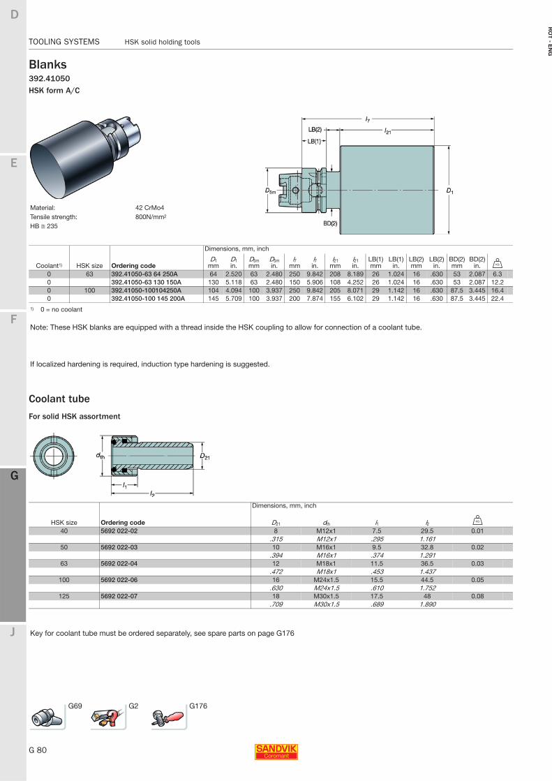
G 80
TOOLING SYSTEMS HSK solid holding tools
E
F
G
J
D
G
RO
T - E
NG
TOOLING SYSTEMS HSK solid holding tools
Blanks392.41050HSK form A/C
Coolant tube
For solid HSK assortment
Material: 42 CrMo4Tensile strength: 800N/mm2
HB ≅ 235
Dimensions, mm, inch
Coolant1) HSK size Ordering codeD1
mmD1in.
D5mmm
D5min.
l7mm
l7in.
l21 mm
l21 in.
LB(1)mm
LB(1)in.
LB(2)mm
LB(2)in.
BD(2)mm
BD(2)in. U
0 63 392.41050-63 64 250A 64 2.520 63 2.480 250 9.842 208 8.189 26 1.024 16 .630 53 2.087 6.30 392.41050-63 130 150A 130 5.118 63 2.480 150 5.906 108 4.252 26 1.024 16 .630 53 2.087 12.20 100 392.41050-100104250A 104 4.094 100 3.937 250 9.842 205 8.071 29 1.142 16 .630 87.5 3.445 16.40 392.41050-100 145 200A 145 5.709 100 3.937 200 7.874 155 6.102 29 1.142 16 .630 87.5 3.445 22.4
1) 0 = no coolant
Note: These HSK blanks are equipped with a thread inside the HSK coupling to allow for connection of a coolant tube.
If localized hardening is required, induction type hardening is suggested.
Dimensions, mm, inch
HSK size Ordering code D21 dth l1 l2 U
40 5692 022-02 8 M12x1 7.5 29.5 0.01.315 M12x1 .295 1.161
50 5692 022-03 10 M16x1 9.5 32.8 0.02.394 M16x1 .374 1.291
63 5692 022-04 12 M18x1 11.5 36.5 0.03.472 M18x1 .453 1.437
100 5692 022-06 16 M24x1.5 15.5 44.5 0.05.630 M24x1.5 .610 1.752
125 5692 022-07 18 M30x1.5 17.5 48 0.08.709 M30x1.5 .689 1.890
Key for coolant tube must be ordered separately, see spare parts on page G176
G69 G2 G176
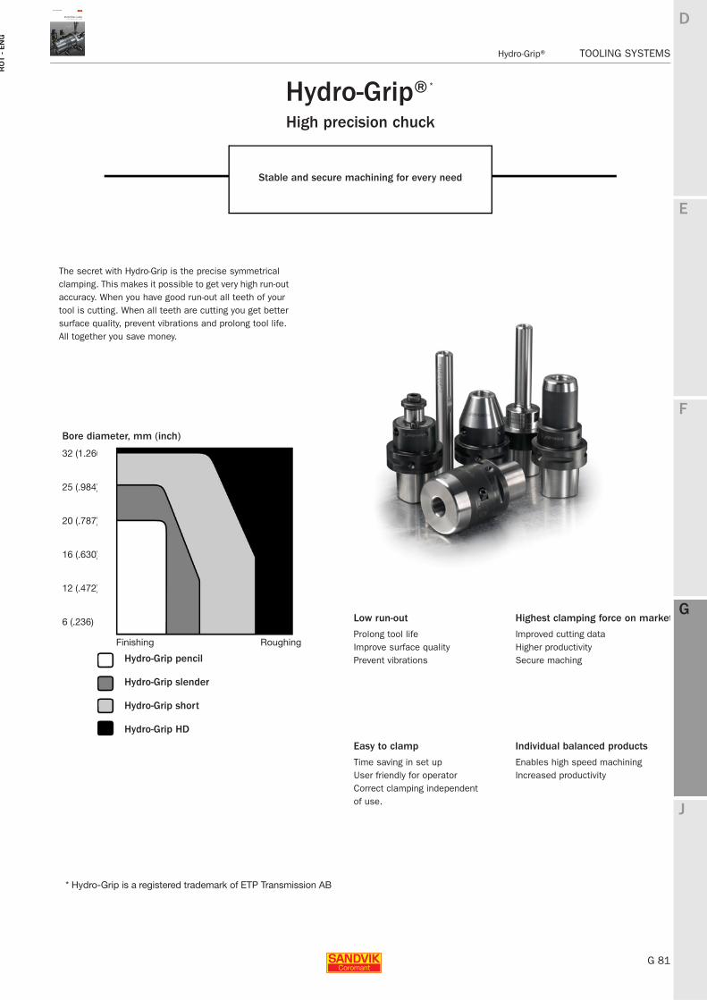
E
G 81
F
G
J
D
G
Hydro-Grip® TOOLING SYSTEMS
RO
T -
EN
G
TOOLING SYSTEMS Hydro-Grip®
Hydro-Grip®High precision chuck
Stable and secure machining for every need
The secret with Hydro-Grip is the precise symmetrical clamping. This makes it possible to get very high run-out accuracy. When you have good run-out all teeth of your tool is cutting. When all teeth are cutting you get better surface quality, prevent vibrations and prolong tool life. All together you save money.
*
* Hydro-Grip is a registered trademark of ETP Transmission AB
Bore diameter, mm (inch)
32 (1.260)
25 (.984)
20 (.787)
16 (.630)
12 (.472)
6 (.236) Low run-out
Prolong tool life Improve surface qualityPrevent vibrations
Easy to clamp
Time saving in set upUser friendly for operatorCorrect clamping independentof use.
Highest clamping force on market
Improved cutting dataHigher productivitySecure maching
Individual balanced products
Enables high speed machiningIncreased productivity
Hydro-Grip HD
Hydro-Grip short
Hydro-Grip slender
Hydro-Grip pencil
Finishing Roughing
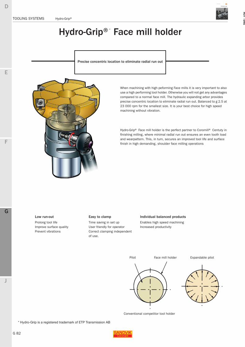
G 82
TOOLING SYSTEMS Hydro-Grip®
E
F
G
J
D
G
RO
T - E
NG
TOOLING SYSTEMS Hydro-Grip®
Hydro-Grip® Face mill holder
Precise concentric location to eliminate radial run out
When machining with high peforming Face mills it is very important to also use a high performing tool holder. Otherwise you will not get any advantages compared to a normal face mill. The hydraulic expanding arbor provides precise concentric location to eliminate radial run out. Balanced to g 2.5 at 23 000 rpm for the smallest size. It is your best choice for high speed machining without vibration.
Hydro-Grip® Face mill holder is the perfect partner to Coromill® Centuty in finishing milling, where minimal radial run out ensures an even tooth load and wearpattern. This, in turn, secures an improved tool life and surface finish in high demanding, shoulder face milling operations
Pilot Face mill holder
Conventional competitor tool holder
Expandable pilot
Low run-out
Prolong tool life Improve surface qualityPrevent vibrations
Easy to clamp
Time saving in set upUser friendly for operatorCorrect clamping independentof use.
Individual balanced products
Enables high speed machiningIncreased productivity
* Hydro-Grip is a registered trademark of ETP Transmission AB
*
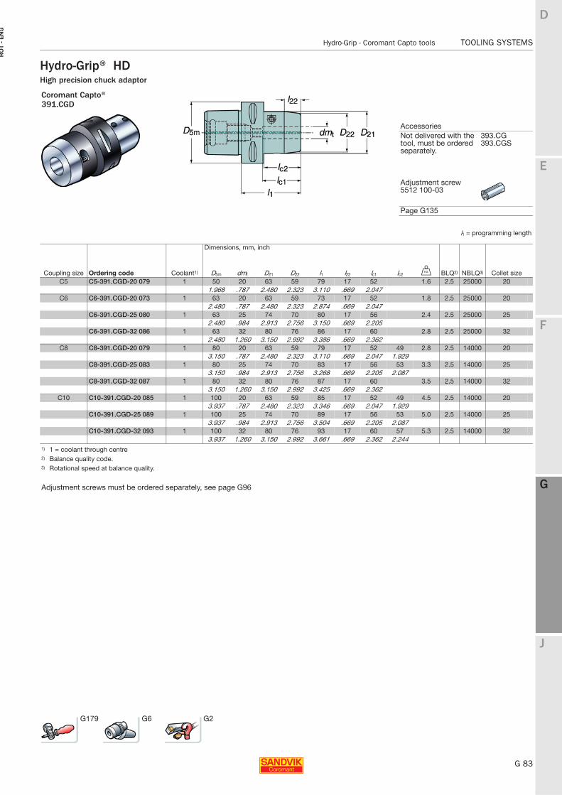
E
G 83
F
G
J
D
G
Hydro-Grip - Coromant Capto tools TOOLING SYSTEMS
RO
T -
EN
G
TOOLING SYSTEMS Hydro-Grip - Coromant Capto tools
Hydro-Grip® HDHigh precision chuck adaptor
Coromant Capto®391.CGD
AccessoriesNot delivered with the tool, must be ordered separately.
393.CG393.CGS
Adjustment screw 5512 100-03
Page G135
l1 = programming length
Dimensions, mm, inch
Coupling size Ordering code Coolant1) D5m dmt D21 D22 l1 l22 lc1 lc2 U BLQ2) NBLQ3) Collet sizeC5 C5-391.CGD-20 079 1 50 20 63 59 79 17 52 1.6 2.5 25000 20
1.968 .787 2.480 2.323 3.110 .669 2.047C6 C6-391.CGD-20 073 1 63 20 63 59 73 17 52 1.8 2.5 25000 20
2.480 .787 2.480 2.323 2.874 .669 2.047C6-391.CGD-25 080 1 63 25 74 70 80 17 56 2.4 2.5 25000 25
2.480 .984 2.913 2.756 3.150 .669 2.205C6-391.CGD-32 086 1 63 32 80 76 86 17 60 2.8 2.5 25000 32
2.480 1.260 3.150 2.992 3.386 .669 2.362C8 C8-391.CGD-20 079 1 80 20 63 59 79 17 52 49 2.8 2.5 14000 20
3.150 .787 2.480 2.323 3.110 .669 2.047 1.929C8-391.CGD-25 083 1 80 25 74 70 83 17 56 53 3.3 2.5 14000 25
3.150 .984 2.913 2.756 3.268 .669 2.205 2.087C8-391.CGD-32 087 1 80 32 80 76 87 17 60 3.5 2.5 14000 32
3.150 1.260 3.150 2.992 3.425 .669 2.362C10 C10-391.CGD-20 085 1 100 20 63 59 85 17 52 49 4.5 2.5 14000 20
3.937 .787 2.480 2.323 3.346 .669 2.047 1.929C10-391.CGD-25 089 1 100 25 74 70 89 17 56 53 5.0 2.5 14000 25
3.937 .984 2.913 2.756 3.504 .669 2.205 2.087C10-391.CGD-32 093 1 100 32 80 76 93 17 60 57 5.3 2.5 14000 32
3.937 1.260 3.150 2.992 3.661 .669 2.362 2.2441) 1 = coolant through centre2) Balance quality code.3) Rotational speed at balance quality.
Adjustment screws must be ordered separately, see page G96
G179 G6 G2
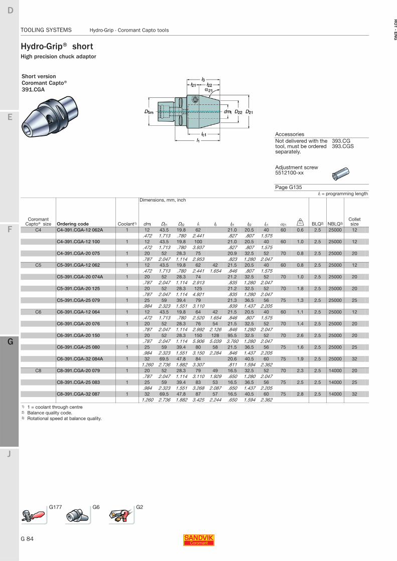
G 84
TOOLING SYSTEMS Hydro-Grip - Coromant Capto tools
E
F
G
J
D
G
RO
T - E
NG
TOOLING SYSTEMS Hydro-Grip - Coromant Capto tools
Hydro-Grip® shortHigh precision chuck adaptor
Short versionCoromant Capto®391.CGA
AccessoriesNot delivered with the tool, must be ordered separately.
393.CG393.CGS
Adjustment screw 5512100-xx
Page G135l1 = programming length
Dimensions, mm, inch
Coromant Capto® size Ordering code Coolant1) dmt D21 D22 l1 l3 l21 l22 lc1 α21 U BLQ2) NBLQ3)
Collet size
C4 C4-391.CGA-12 062A 1 12 43.5 19.8 62 21.0 20.5 40 60 0.6 2.5 25000 12.472 1.713 .780 2.441 .827 .807 1.575
C4-391.CGA-12 100 1 12 43.5 19.8 100 21.0 20.5 40 60 1.0 2.5 25000 12.472 1.713 .780 3.937 .827 .807 1.575
C4-391.CGA-20 075 1 20 52 28.3 75 20.9 32.5 52 70 0.8 2.5 25000 20.787 2.047 1.114 2.953 .823 1.280 2.047
C5 C5-391.CGA-12 062 1 12 43.5 19.8 62 42 21.5 20.5 40 60 0.8 2.5 25000 12.472 1.713 .780 2.441 1.654 .846 .807 1.575
C5-391.CGA-20 074A 1 20 52 28.3 74 21.2 32.5 52 70 1.0 2.5 25000 20.787 2.047 1.114 2.913 .835 1.280 2.047
C5-391.CGA-20 125 1 20 52 28.3 125 21.2 32.5 52 70 1.8 2.5 25000 20.787 2.047 1.114 4.921 .835 1.280 2.047
C5-391.CGA-25 079 1 25 59 39.4 79 21.3 36.5 56 75 1.3 2.5 25000 25.984 2.323 1.551 3.110 .839 1.437 2.205
C6 C6-391.CGA-12 064 1 12 43.5 19.8 64 42 21.5 20.5 40 60 1.1 2.5 25000 12.472 1.713 .780 2.520 1.654 .846 .807 1.575
C6-391.CGA-20 076 1 20 52 28.3 76 54 21.5 32.5 52 70 1.4 2.5 25000 20.787 2.047 1.114 2.992 2.126 .846 1.280 2.047
C6-391.CGA-20 150 1 20 52 28.3 150 128 95.5 32.5 52 70 2.6 2.5 25000 20.787 2.047 1.114 5.906 5.039 3.760 1.280 2.047
C6-391.CGA-25 080 1 25 59 39.4 80 58 21.5 36.5 56 75 1.6 2.5 25000 25.984 2.323 1.551 3.150 2.284 .846 1.437 2.205
C6-391.CGA-32 084A 1 32 69.5 47.8 84 20.6 40.5 60 75 1.9 2.5 25000 321.260 2.736 1.882 3.307 .811 1.594 2.362
C8 C8-391.CGA-20 079 1 20 52 28.3 79 49 16.5 32.5 52 70 2.3 2.5 14000 20.787 2.047 1.114 3.110 1.929 .650 1.280 2.047
C8-391.CGA-25 083 1 25 59 39.4 83 53 16.5 36.5 56 75 2.5 2.5 14000 25.984 2.323 1.551 3.268 2.087 .650 1.437 2.205
C8-391.CGA-32 087 1 32 69.5 47.8 87 57 16.5 40.5 60 75 2.8 2.5 14000 321.260 2.736 1.882 3.425 2.244 .650 1.594 2.362
1) 1 = coolant through centre2) Balance quality code.3) Rotational speed at balance quality.
G177 G6 G2
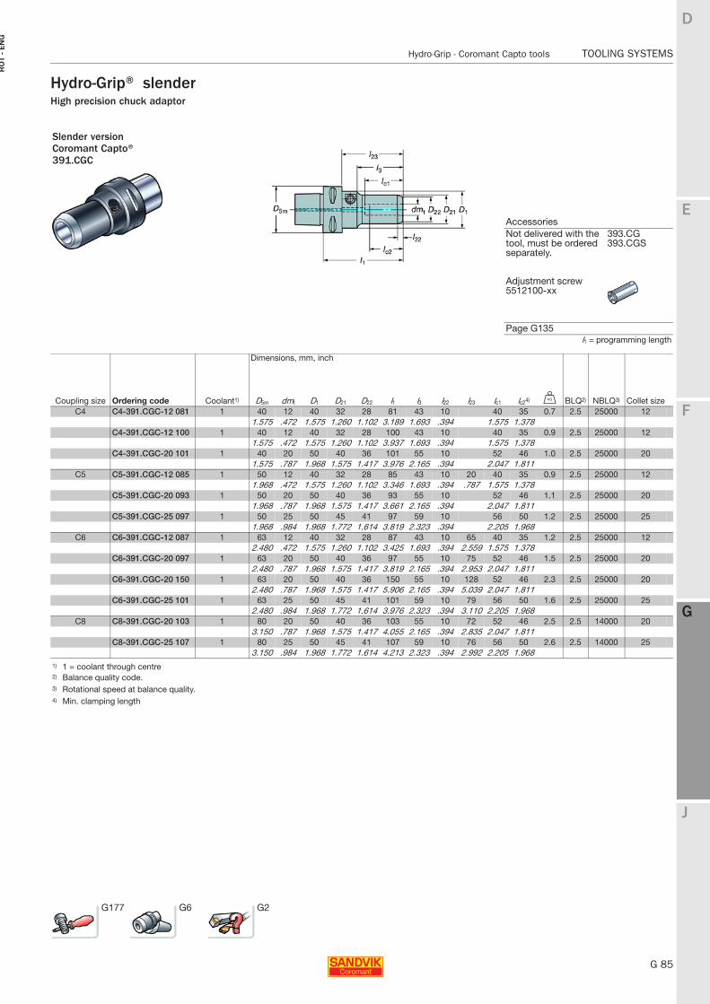
E
G 85
F
G
J
D
G
Hydro-Grip - Coromant Capto tools TOOLING SYSTEMS
RO
T -
EN
G
TOOLING SYSTEMS Hydro-Grip - Coromant Capto tools
Hydro-Grip® slenderHigh precision chuck adaptor
Slender versionCoromant Capto®391.CGC
AccessoriesNot delivered with the tool, must be ordered separately.
393.CG393.CGS
Adjustment screw 5512100-xx
Page G135l1 = programming length
Dimensions, mm, inch
Coupling size Ordering code Coolant1) D5m dmt D1 D21 D22 l1 l3 l22 l23 lc1 lc24) U BLQ2) NBLQ3) Collet sizeC4 C4-391.CGC-12 081 1 40 12 40 32 28 81 43 10 40 35 0.7 2.5 25000 12
1.575 .472 1.575 1.260 1.102 3.189 1.693 .394 1.575 1.378C4-391.CGC-12 100 1 40 12 40 32 28 100 43 10 40 35 0.9 2.5 25000 12
1.575 .472 1.575 1.260 1.102 3.937 1.693 .394 1.575 1.378C4-391.CGC-20 101 1 40 20 50 40 36 101 55 10 52 46 1.0 2.5 25000 20
1.575 .787 1.968 1.575 1.417 3.976 2.165 .394 2.047 1.811C5 C5-391.CGC-12 085 1 50 12 40 32 28 85 43 10 20 40 35 0.9 2.5 25000 12
1.968 .472 1.575 1.260 1.102 3.346 1.693 .394 .787 1.575 1.378C5-391.CGC-20 093 1 50 20 50 40 36 93 55 10 52 46 1.1 2.5 25000 20
1.968 .787 1.968 1.575 1.417 3.661 2.165 .394 2.047 1.811C5-391.CGC-25 097 1 50 25 50 45 41 97 59 10 56 50 1.2 2.5 25000 25
1.968 .984 1.968 1.772 1.614 3.819 2.323 .394 2.205 1.968C6 C6-391.CGC-12 087 1 63 12 40 32 28 87 43 10 65 40 35 1.2 2.5 25000 12
2.480 .472 1.575 1.260 1.102 3.425 1.693 .394 2.559 1.575 1.378C6-391.CGC-20 097 1 63 20 50 40 36 97 55 10 75 52 46 1.5 2.5 25000 20
2.480 .787 1.968 1.575 1.417 3.819 2.165 .394 2.953 2.047 1.811C6-391.CGC-20 150 1 63 20 50 40 36 150 55 10 128 52 46 2.3 2.5 25000 20
2.480 .787 1.968 1.575 1.417 5.906 2.165 .394 5.039 2.047 1.811C6-391.CGC-25 101 1 63 25 50 45 41 101 59 10 79 56 50 1.6 2.5 25000 25
2.480 .984 1.968 1.772 1.614 3.976 2.323 .394 3.110 2.205 1.968C8 C8-391.CGC-20 103 1 80 20 50 40 36 103 55 10 72 52 46 2.5 2.5 14000 20
3.150 .787 1.968 1.575 1.417 4.055 2.165 .394 2.835 2.047 1.811C8-391.CGC-25 107 1 80 25 50 45 41 107 59 10 76 56 50 2.6 2.5 14000 25
3.150 .984 1.968 1.772 1.614 4.213 2.323 .394 2.992 2.205 1.9681) 1 = coolant through centre2) Balance quality code.3) Rotational speed at balance quality.4) Min. clamping length
G177 G6 G2
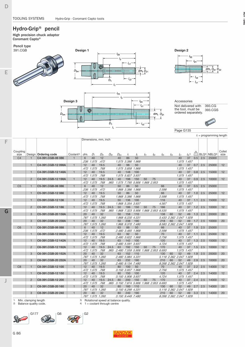
G 86
TOOLING SYSTEMS Hydro-Grip - Coromant Capto tools
E
F
G
J
D
G
RO
T - E
NG
TOOLING SYSTEMS Hydro-Grip - Coromant Capto tools
Hydro-Grip® pencilHigh precision chuck adaptorCoromant Capto®
Pencil type391.CGB Design 1 Design 2
Design 3 AccessoriesNot delivered with the tool, must be ordered separately.
393.CG393.CGS
Page G135l1 = programming length
Dimensions, mm, inch
Coupling size Design Ordering code Coolant4) dmt D1 D21 D22 D5m l1 l3 l21 l22 l23 l24 lc1 lc21) U BLQ2) NBLQ3)
Collet size
C4 1 C4-391.CGB-06 086 1 6 40 12 40 86 50 40 37 0.5 2.5 25000.236 1.575 .472 1.575 3.386 1.968 1.575 1.457
1 C4-391.CGB-12 098A 1 12 40 19.5 40 98 50 40 37 0.7 2.5 25000 12.472 1.575 .768 1.575 3.858 1.968 1.575 1.457
1 C4-391.CGB-12 148A 1 12 40 19.5 40 148 100 40 37 0.8 2.5 15000 12.472 1.575 .768 1.575 5.827 3.937 1.575 1.457
2 C4-391.CGB-12 198A 1 12 40 19.5 24.5 40 198 150 50 75 40 37 0.9 2.5 10000 12.472 1.575 .768 .965 1.575 7.795 5.906 1.968 2.953 1.575 1.457
C5 1 C5-391.CGB-06 086 1 6 40 12 50 86 50 66 40 37 0.5 2.5 25000.236 1.575 .472 1.968 3.386 1.968 2.598 1.575 1.457
1 C5-391.CGB-12 086 1 12 40 19.5 50 86 50 66 40 37 1.0 2.5 25000 12.472 1.575 .768 1.968 3.386 1.968 2.598 1.575 1.457
1 C5-391.CGB-12 136 1 12 40 19.5 50 136 100 116 40 37 1.1 2.5 15000 12.472 1.575 .768 1.968 5.354 3.937 4.567 1.575 1.457
2 C5-391.CGB-12 186 1 12 40 19.5 24.5 50 186 150 50 75 166 40 37 1.2 2.5 10000 12.472 1.575 .768 .965 1.968 7.323 5.906 1.968 2.953 6.535 1.575 1.457
3 C5-391.CGB-20 158A 1 20 40 32 50 158 110 138 60 52 49 1.3 2.5 20000 20.787 1.575 1.260 1.968 6.220 4.331 5.433 2.362 2.047 1.929
3 C5-391.CGB-20 238A 1 20 40 32 50 238 190 218 60 52 49 1.7 2.5 10000 20.787 1.575 1.260 1.968 9.370 7.480 8.583 2.362 2.047 1.929
C6 1 C6-391.CGB-06 088 1 6 40 12 63 88 50 66 40 37 1.9 2.5 25000.236 1.575 .472 2.480 3.465 1.968 2.598 1.575 1.457
1 C6-391.CGB-12 092A 1 12 40 19.5 63 92 50 70 40 37 1.1 2.5 25000 12.472 1.575 .768 2.480 3.622 1.968 2.756 1.575 1.457
1 C6-391.CGB-12 142A 1 12 40 19.5 63 142 100 120 40 37 1.3 2.5 15000 12.472 1.575 .768 2.480 5.591 3.937 4.724 1.575 1.457
2 C6-391.CGB-12 192A 1 12 40 19.5 24.5 63 192 150 50 75 170 40 37 1.5 2.5 10000 12.472 1.575 .768 .965 2.480 7.559 5.906 1.968 2.953 6.693 1.575 1.457
3 C6-391.CGB-20 152A 1 20 40 32 63 152 110 130 60 52 49 1.9 2.5 20000 20.787 1.575 1.260 2.480 5.984 4.331 5.118 2.362 2.047 1.929
3 C6-391.CGB-20 232A 1 20 40 32 63 232 190 210 60 52 49 2.9 2.5 10000 20.787 1.575 1.260 2.480 9.134 7.480 8.268 2.362 2.047 1.929
C8 1 C8-391.CGB-12 100 1 12 40 19.5 80 100 50 70 40 37 2.2 2.5 14000 12.472 1.575 .768 3.150 3.937 1.968 2.756 1.575 1.457
1 C8-391.CGB-12 150 1 12 40 19.5 80 150 100 120 40 37 2.4 2.5 14000 12.472 1.575 .768 3.150 5.906 3.937 4.724 1.575 1.457
2 C8-391.CGB-12 200 1 12 40 19.5 24.5 80 200 150 50 75 170 40 37 2.4 2.5 14000 12.472 1.575 .768 .965 3.150 7.874 5.906 1.968 2.953 6.693 1.575 1.457
3 C8-391.CGB-20 160 1 20 40 32 80 160 110 130 60 52 49 2.7 2.5 14000 20.787 1.575 1.260 3.150 6.299 4.331 5.118 2.362 2.047 1.929
3 C8-391.CGB-20 240 1 20 40 32 80 240 190 210 60 52 49 3.3 2.5 14000 20.787 1.575 1.260 3.150 9.449 7.480 8.268 2.362 2.047 1.929
1) Min. clamping length 3) Rotational speed at balance quality.2) Balance quality code. 4) 1 = coolant through centre
G177 G6 G2
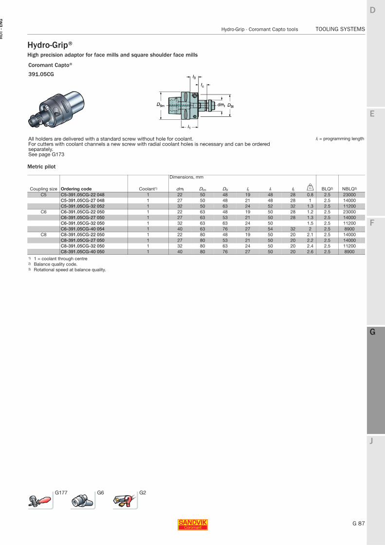
E
G 87
F
G
J
D
G
Hydro-Grip - Coromant Capto tools TOOLING SYSTEMS
RO
T -
EN
G
TOOLING SYSTEMS Hydro-Grip - Coromant Capto tools
Hydro-Grip®High precision adaptor for face mills and square shoulder face mills
Metric pilot
Coromant Capto®
391.05CG
All holders are delivered with a standard screw without hole for coolant.For cutters with coolant channels a new screw with radial coolant holes is necessary and can be ordered separately.See page G173
l1 = programming length
Dimensions, mm
Coupling size Ordering code Coolant1) dmt D5m D5t lc l1 l3 U BLQ2) NBLQ3)
C5 C5-391.05CG-22 048 1 22 50 48 19 48 28 0.8 2.5 23000C5-391.05CG-27 048 1 27 50 48 21 48 28 1 2.5 14000C5-391.05CG-32 052 1 32 50 63 24 52 32 1.3 2.5 11200
C6 C6-391.05CG-22 050 1 22 63 48 19 50 28 1.2 2.5 23000C6-391.05CG-27 050 1 27 63 53 21 50 28 1.3 2.5 14000C6-391.05CG-32 050 1 32 63 63 24 50 1.5 2.5 11200C6-391.05CG-40 054 1 40 63 76 27 54 32 2 2.5 8900
C8 C8-391.05CG-22 050 1 22 80 48 19 50 20 2.1 2.5 14000C8-391.05CG-27 050 1 27 80 53 21 50 20 2.2 2.5 14000C8-391.05CG-32 050 1 32 80 63 24 50 20 2.4 2.5 11200C8-391.05CG-40 050 1 40 80 76 27 50 20 2.6 2.5 8900
1) 1 = coolant through centre2) Balance quality code.3) Rotational speed at balance quality.
G177 G6 G2
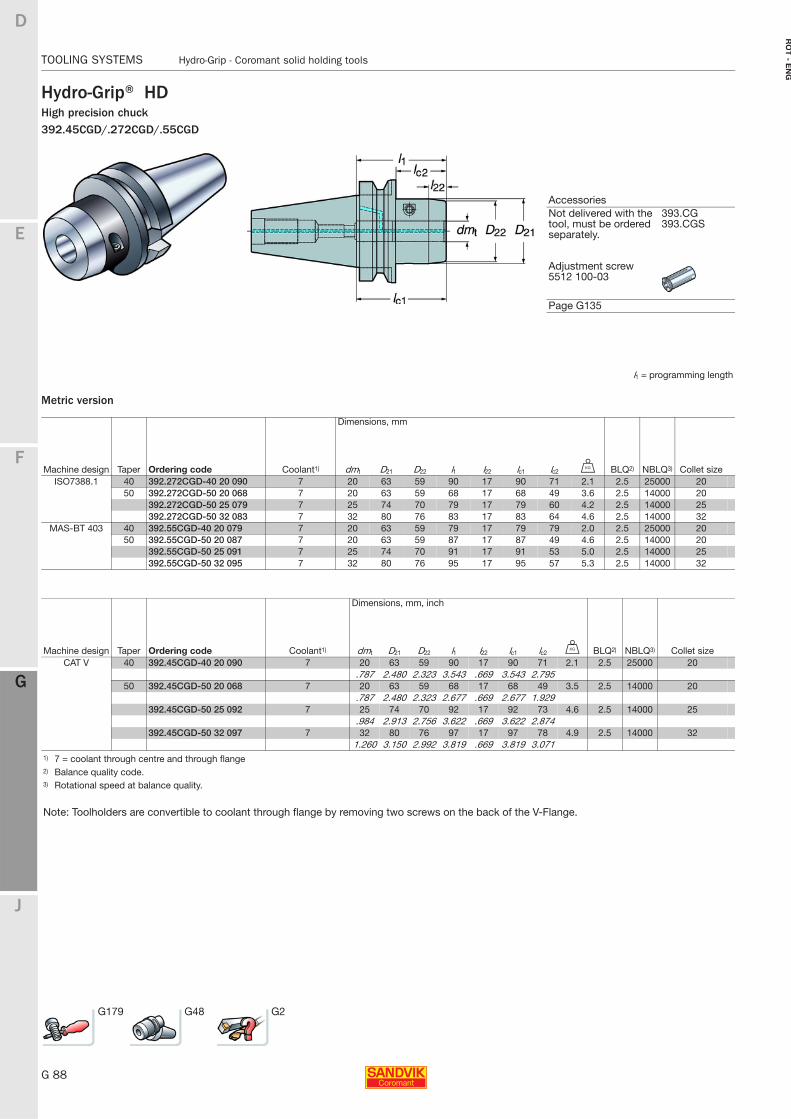
G 88
TOOLING SYSTEMS Hydro-Grip - Coromant solid holding tools
E
F
G
J
D
G
RO
T - E
NG
TOOLING SYSTEMS Hydro-Grip - Coromant solid holding tools
Hydro-Grip® HDHigh precision chuck392.45CGD/.272CGD/.55CGD
Metric version
AccessoriesNot delivered with the tool, must be ordered separately.
393.CG393.CGS
Adjustment screw 5512 100-03
Page G135
l1 = programming length
Dimensions, mm
Machine design Taper Ordering code Coolant1) dmt D21 D22 l1 l22 lc1 lc2 U BLQ2) NBLQ3) Collet sizeISO7388.1 40 392.272CGD-40 20 090 7 20 63 59 90 17 90 71 2.1 2.5 25000 20
50 392.272CGD-50 20 068 7 20 63 59 68 17 68 49 3.6 2.5 14000 20392.272CGD-50 25 079 7 25 74 70 79 17 79 60 4.2 2.5 14000 25392.272CGD-50 32 083 7 32 80 76 83 17 83 64 4.6 2.5 14000 32
MAS-BT 403 40 392.55CGD-40 20 079 7 20 63 59 79 17 79 79 2.0 2.5 25000 2050 392.55CGD-50 20 087 7 20 63 59 87 17 87 49 4.6 2.5 14000 20
392.55CGD-50 25 091 7 25 74 70 91 17 91 53 5.0 2.5 14000 25392.55CGD-50 32 095 7 32 80 76 95 17 95 57 5.3 2.5 14000 32
Dimensions, mm, inch
Machine design Taper Ordering code Coolant1) dmt D21 D22 l1 l22 lc1 lc2 U BLQ2) NBLQ3) Collet sizeCAT V 40 392.45CGD-40 20 090 7 20 63 59 90 17 90 71 2.1 2.5 25000 20
.787 2.480 2.323 3.543 .669 3.543 2.79550 392.45CGD-50 20 068 7 20 63 59 68 17 68 49 3.5 2.5 14000 20
.787 2.480 2.323 2.677 .669 2.677 1.929392.45CGD-50 25 092 7 25 74 70 92 17 92 73 4.6 2.5 14000 25
.984 2.913 2.756 3.622 .669 3.622 2.874392.45CGD-50 32 097 7 32 80 76 97 17 97 78 4.9 2.5 14000 32
1.260 3.150 2.992 3.819 .669 3.819 3.0711) 7 = coolant through centre and through flange2) Balance quality code.3) Rotational speed at balance quality.
Note: Toolholders are convertible to coolant through flange by removing two screws on the back of the V-Flange.
G179 G48 G2
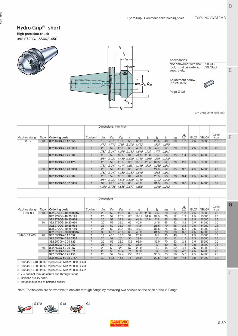
E
G 89
F
G
J
D
G
Hydro-Grip - Coromant solid holding tools TOOLING SYSTEMS
RO
T -
EN
G
TOOLING SYSTEMS Hydro-Grip - Coromant solid holding tools
Hydro-Grip® shortHigh precision chuck392.272CG/ .55CG/ .45G
AccessoriesNot delivered with the tool, must be ordered separately.
393.CG393.CGS
Adjustment screw 5512100-xx
Page G135
l1 = programming length
Dimensions, mm, inch
Machine design Taper Ordering code Coolant4) dmt D21 D22 l1 l3 l21 l22 lc1 α21 U BLQ5) NBLQ6)Collet size
CAT V 40 392.45CG-40 12 056 7 12 43.5 19.8 56 36.9 20.5 40 60 1.2 2.5 25000 12.472 1.713 .780 2.205 1.453 .807 1.575
392.45CG-40 20 0601) 7 20 52 27.3 60 40.9 18.3 4.5 52 20 1.3 2.5 25000 20.787 2.047 1.075 2.362 1.610 .720 .177 2.047
392.45CG-40 25 064 7 25 59 37.6 64 44.9 26.8 7.5 56 35 1.4 2.5 14000 25.984 2.323 1.480 2.520 1.768 1.055 .295 2.205
392.45CG-40 20 125 7 20 52 28.3 125 105.9 20.4 32.5 52 70 2.0 2.5 25000 20.787 2.047 1.114 4.921 4.169 .803 1.280 2.047
50 392.45CG-50 20 0602) 7 20 52 29.2 60 40.9 24.5 52 65 3.2 2.5 14000 20.787 2.047 1.150 2.362 1.610 .965 2.047
392.45CG-50 25 064 7 25 59 38.3 64 44.9 28.5 56 70 3.4 2.5 14000 25.984 2.323 1.508 2.520 1.768 1.122 2.205
392.45CG-50 32 0683) 7 32 69.5 46.6 68 48.9 31.5 60 70 3.6 2.5 14000 321.260 2.736 1.835 2.677 1.925 1.240 2.362
Dimensions
Machine design Taper Ordering code Coolant1) dmt D21 D22 l1 l3 l21 l22 α21 lc1 U BLQ2) NBLQ3)Collet size
ISO7388.1 40 392.272CG-40 20 060A 7 20 52 27.3 60 40.9 23.8 4.5 70 52 1.3 2.5 25000 20392.272CG-40 20 125 7 20 52 28.3 125 105.9 51.8 32.5 70 52 1.9 2.5 25000 20392.272CG-40 25 064 7 25 59 37.6 64 44.9 26.8 7.5 35 56 1.4 2.5 25000 25
50 392.272CG-50 20 060 7 20 52 29.2 60 40.9 24.5 65 52 3.2 2.5 14000 20392.272CG-50 25 064 7 25 59 38.3 64 44.9 28.5 70 56 3.3 2.5 14000 25392.272CG-50 25 150 7 25 59 39.4 150 130.9 36.5 75 56 5.1 2.5 14000 25392.272CG-50 32 068A 7 32 69.5 46.6 68 48.9 31.5 70 60 3.5 2.5 14000 32
MAS-BT 403 40 392.55CG-40 12 052 7 12 43.5 19.3 52 25.0 8.5 35 40 1.2 2.5 25000 12392.55CG-40 20 056A 7 20 52 26 56 29.0 13 45 52 1.3 2.5 25000 20392.55CG-40 20 125 7 20 52 28.3 125 98.0 32.5 70 52 2.3 2.5 25000 20392.55CG-40 25 060 7 25 59 39.4 60 33.0 17 60 56 1.4 2.5 25000 25
50 392.55CG-50 20 067 7 20 52 26 67 29.0 13 45 52 4.1 2.5 14000 20392.55CG-50 25 071 7 25 59 39.4 71 33.0 17 60 56 4.2 2.5 14000 25392.55CG-50 25 150 7 25 59 39.4 150 112.0 36.5 75 56 5.7 2.5 14000 25392.55CG-50 32 075A 7 32 69.5 45.8 75 37.0 20.5 60 60 4.3 2.5 14000 32
1) 392.45CG-40 20 060 replaces 40 MM-VF 060 CG202) 392.45CG-50 20 060 replaces 50 MM-VF 060 CG203) 392.45CG-50 32 068 replaces 50 MM-VF 068 CG324) 7 = coolant through centre and through flange5) Balance quality code.6) Rotational speed at balance quality.
Note: Toolholders are convertible to coolant through flange by removing two screws on the back of the V-Flange.
G179 G48 G2
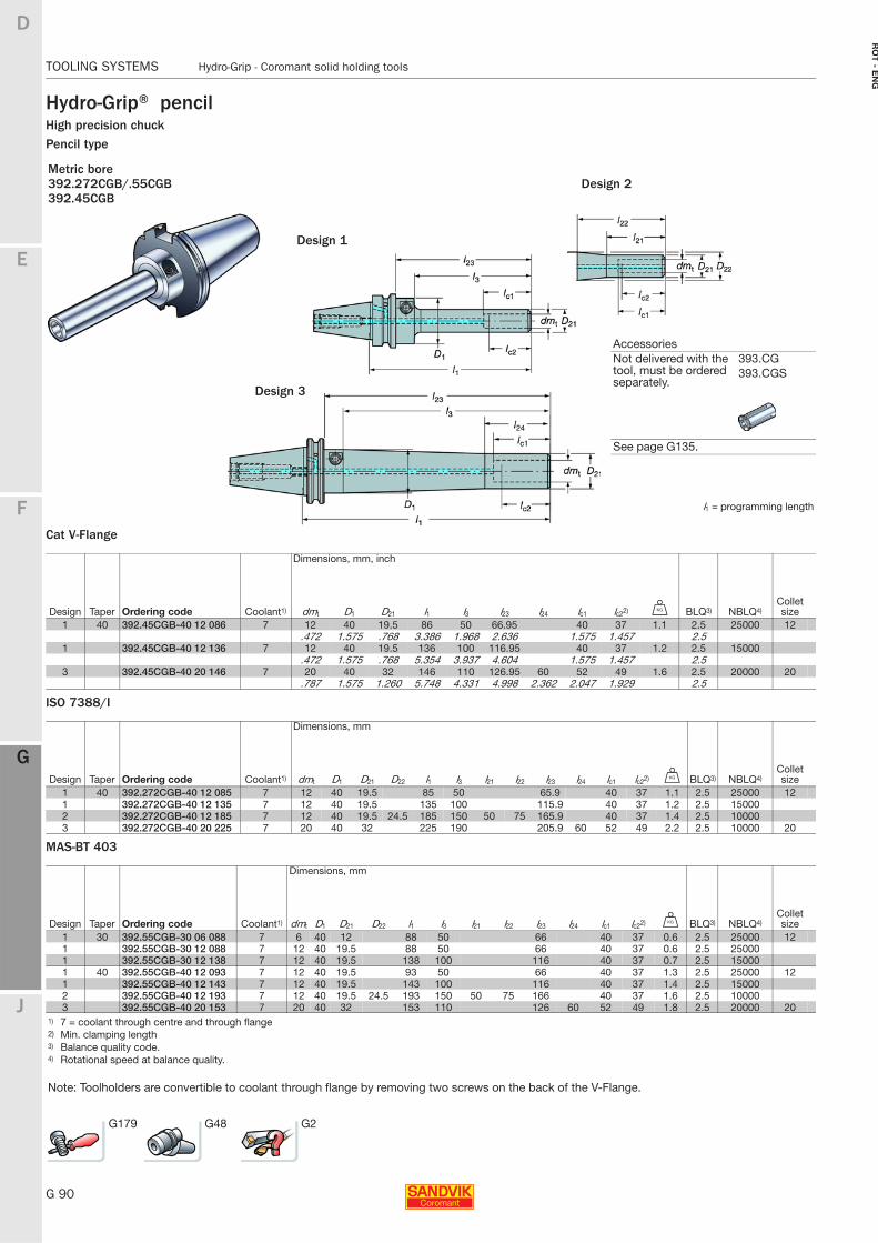
G 90
TOOLING SYSTEMS Hydro-Grip - Coromant solid holding tools
E
F
G
J
D
G
RO
T - E
NG
TOOLING SYSTEMS Hydro-Grip - Coromant solid holding tools
Hydro-Grip® pencilHigh precision chuckPencil type
Cat V-Flange
ISO 7388/I
MAS-BT 403
Metric bore392.272CGB/.55CGB Design 2392.45CGB
l1 = programming length
Dimensions, mm, inch
Design Taper Ordering code Coolant1) dmt D1 D21 l1 l3 l23 l24 lc1 lc22) U BLQ3) NBLQ4)Collet size
1 40 392.45CGB-40 12 086 7 12 40 19.5 86 50 66.95 40 37 1.1 2.5 25000 12.472 1.575 .768 3.386 1.968 2.636 1.575 1.457 2.5
1 392.45CGB-40 12 136 7 12 40 19.5 136 100 116.95 40 37 1.2 2.5 15000.472 1.575 .768 5.354 3.937 4.604 1.575 1.457 2.5
3 392.45CGB-40 20 146 7 20 40 32 146 110 126.95 60 52 49 1.6 2.5 20000 20.787 1.575 1.260 5.748 4.331 4.998 2.362 2.047 1.929 2.5
Dimensions, mm
Design Taper Ordering code Coolant1) dmt D1 D21 D22 l1 l3 l21 l22 l23 l24 lc1 lc22) U BLQ3) NBLQ4)Collet size
1 40 392.272CGB-40 12 085 7 12 40 19.5 85 50 65.9 40 37 1.1 2.5 25000 121 392.272CGB-40 12 135 7 12 40 19.5 135 100 115.9 40 37 1.2 2.5 150002 392.272CGB-40 12 185 7 12 40 19.5 24.5 185 150 50 75 165.9 40 37 1.4 2.5 100003 392.272CGB-40 20 225 7 20 40 32 225 190 205.9 60 52 49 2.2 2.5 10000 20
Dimensions, mm
Design Taper Ordering code Coolant1) dmt D1 D21 D22 l1 l3 l21 l22 l23 l24 lc1 lc22) U BLQ3) NBLQ4)Collet size
1 30 392.55CGB-30 06 088 7 6 40 12 88 50 66 40 37 0.6 2.5 25000 121 392.55CGB-30 12 088 7 12 40 19.5 88 50 66 40 37 0.6 2.5 250001 392.55CGB-30 12 138 7 12 40 19.5 138 100 116 40 37 0.7 2.5 150001 40 392.55CGB-40 12 093 7 12 40 19.5 93 50 66 40 37 1.3 2.5 25000 121 392.55CGB-40 12 143 7 12 40 19.5 143 100 116 40 37 1.4 2.5 150002 392.55CGB-40 12 193 7 12 40 19.5 24.5 193 150 50 75 166 40 37 1.6 2.5 100003 392.55CGB-40 20 153 7 20 40 32 153 110 126 60 52 49 1.8 2.5 20000 20
1) 7 = coolant through centre and through flange2) Min. clamping length3) Balance quality code.4) Rotational speed at balance quality.
Note: Toolholders are convertible to coolant through flange by removing two screws on the back of the V-Flange.
AccessoriesNot delivered with the tool, must be ordered separately.
393.CG393.CGS
See page G135.
Design 1
Design 3
G179 G48 G2
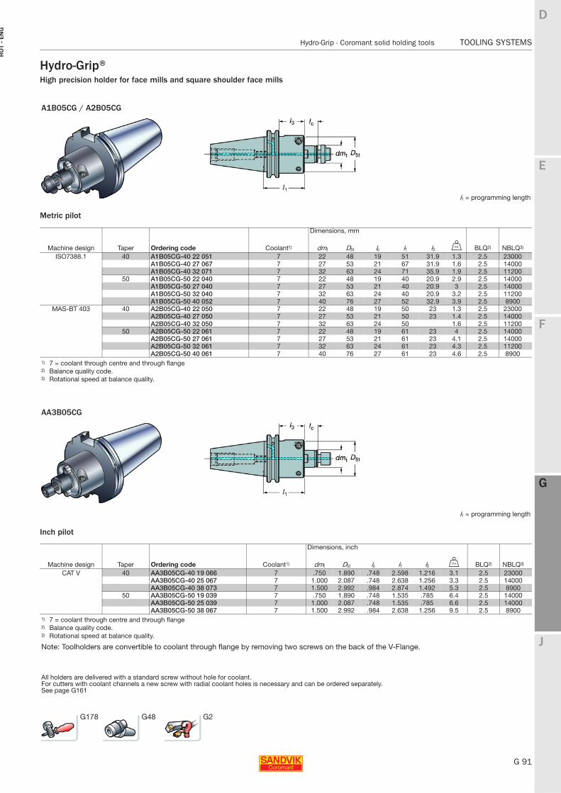
E
G 91
F
G
J
D
G
Hydro-Grip - Coromant solid holding tools TOOLING SYSTEMS
RO
T -
EN
G
TOOLING SYSTEMS Hydro-Grip - Coromant solid holding tools
Hydro-Grip®High precision holder for face mills and square shoulder face mills
Metric pilot
Inch pilot
A1B05CG / A2B05CG
l1 = programming length
Dimensions, mm
Machine design Taper Ordering code Coolant1) dmt D5t lc l1 l3 U BLQ2) NBLQ3)
ISO7388.1 40 A1B05CG-40 22 051 7 22 48 19 51 31.9 1.3 2.5 23000A1B05CG-40 27 067 7 27 53 21 67 31.9 1.6 2.5 14000A1B05CG-40 32 071 7 32 63 24 71 35.9 1.9 2.5 11200
50 A1B05CG-50 22 040 7 22 48 19 40 20.9 2.9 2.5 14000A1B05CG-50 27 040 7 27 53 21 40 20.9 3 2.5 14000A1B05CG-50 32 040 7 32 63 24 40 20.9 3.2 2.5 11200A1B05CG-50 40 052 7 40 76 27 52 32.9 3.9 2.5 8900
MAS-BT 403 40 A2B05CG-40 22 050 7 22 48 19 50 23 1.3 2.5 23000A2B05CG-40 27 050 7 27 53 21 50 23 1.4 2.5 14000A2B05CG-40 32 050 7 32 63 24 50 1.6 2.5 11200
50 A2B05CG-50 22 061 7 22 48 19 61 23 4 2.5 14000A2B05CG-50 27 061 7 27 53 21 61 23 4.1 2.5 14000A2B05CG-50 32 061 7 32 63 24 61 23 4.3 2.5 11200A2B05CG-50 40 061 7 40 76 27 61 23 4.6 2.5 8900
1) 7 = coolant through centre and through flange2) Balance quality code.3) Rotational speed at balance quality.
AA3B05CG
l1 = programming length
Dimensions, inch
Machine design Taper Ordering code Coolant1) dmt D5t lc l1 l3 V BLQ2) NBLQ3)
CAT V 40 AA3B05CG-40 19 066 7 .750 1.890 .748 2.598 1.216 3.1 2.5 23000AA3B05CG-40 25 067 7 1.000 2.087 .748 2.638 1.256 3.3 2.5 14000AA3B05CG-40 38 073 7 1.500 2.992 .984 2.874 1.492 5.3 2.5 8900
50 AA3B05CG-50 19 039 7 .750 1.890 .748 1.535 .785 6.4 2.5 14000AA3B05CG-50 25 039 7 1.000 2.087 .748 1.535 .785 6.6 2.5 14000AA3B05CG-50 38 067 7 1.500 2.992 .984 2.638 1.256 9.5 2.5 8900
1) 7 = coolant through centre and through flange2) Balance quality code.3) Rotational speed at balance quality.
Note: Toolholders are convertible to coolant through flange by removing two screws on the back of the V-Flange.
All holders are delivered with a standard screw without hole for coolant.For cutters with coolant channels a new screw with radial coolant holes is necessary and can be ordered separately.See page G161
G178 G48 G2
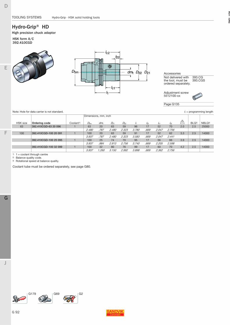
G 92
TOOLING SYSTEMS Hydro-Grip - HSK solid holding tools
E
F
G
J
D
G
RO
T - E
NG
TOOLING SYSTEMS Hydro-Grip - HSK solid holding tools
Hydro-Grip® HDHigh precision chuck adaptor
HSK form A/C392.410CGD
AccessoriesNot delivered with the tool, must be ordered separately.
393.CG393.CGS
Adjustment screw 5512100-xx
Page G135
Note: Hole for data carrier is not standard. l1 = programming length
Dimensions, mm, inch
HSK size Ordering code Coolant1) D5m dmt D21 D22 l1 l22 lc1 lc2 U BLQ2) NBLQ3)
63 392.410CGD-63 20 096 1 63 20 63 59 96 17 52 70 2.0 2.5 250002.480 .787 2.480 2.323 3.780 .669 2.047 2.756
100 392.410CGD-100 20 091 1 100 20 63 59 91 17 52 62 3.3 2.5 140003.937 .787 2.480 2.323 3.583 .669 2.047 2.441
392.410CGD-100 25 095 1 100 25 74 70 95 17 56 66 3.9 2.5 140003.937 .984 2.913 2.756 3.740 .669 2.205 2.598
392.410CGD-100 32 099 1 100 32 80 76 99 17 60 70 4.2 2.5 140003.937 1.260 3.150 2.992 3.898 .669 2.362 2.756
1) 1 = coolant through centre2) Balance quality code.3) Rotational speed at balance quality.
Coolant tube must be ordered separately, see page G80.
G179 G69 G2
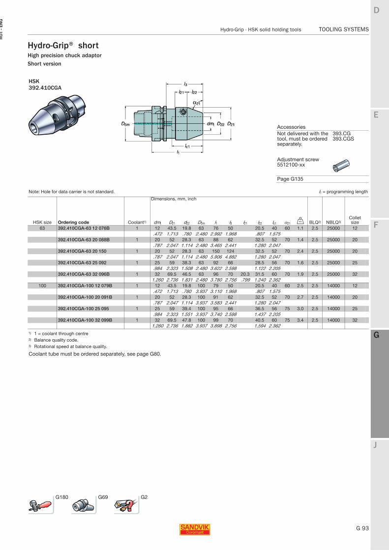
E
G 93
F
G
J
D
G
Hydro-Grip - HSK solid holding tools TOOLING SYSTEMS
RO
T -
EN
G
TOOLING SYSTEMS Hydro-Grip - HSK solid holding tools
Hydro-Grip® shortHigh precision chuck adaptorShort version
HSK 392.410CGA
AccessoriesNot delivered with the tool, must be ordered separately.
393.CG393.CGS
Adjustment screw 5512100-xx
Page G135
Note: Hole for data carrier is not standard. l1 = programming length
Dimensions, mm, inch
HSK size Ordering code Coolant1) dmt D21 d22 D5m l1 l3 l21 l22 lc1 α21 U BLQ2) NBLQ3)Collet size
63 392.410CGA-63 12 076B 1 12 43.5 19.8 63 76 50 20.5 40 60 1.1 2.5 25000 12.472 1.713 .780 2.480 2.992 1.968 .807 1.575
392.410CGA-63 20 088B 1 20 52 28.3 63 88 62 32.5 52 70 1.4 2.5 25000 20.787 2.047 1.114 2.480 3.465 2.441 1.280 2.047
392.410CGA-63 20 150 1 20 52 28.3 63 150 124 32.5 52 70 2.4 2.5 25000 20.787 2.047 1.114 2.480 5.906 4.882 1.280 2.047
392.410CGA-63 25 092 1 25 59 38.3 63 92 66 28.5 56 70 1.6 2.5 25000 25.984 2.323 1.508 2.480 3.622 2.598 1.122 2.205
392.410CGA-63 32 096B 1 32 69.5 46.5 63 96 70 20.3 31.5 60 70 1.9 2.5 25000 321.260 2.736 1.831 2.480 3.780 2.756 .799 1.240 2.362
100 392.410CGA-100 12 079B 1 12 43.5 19.8 100 79 50 20.5 40 60 2.5 2.5 14000 12.472 1.713 .780 3.937 3.110 1.968 .807 1.575
392.410CGA-100 20 091B 1 20 52 28.3 100 91 62 32.5 52 70 2.7 2.5 14000 20.787 2.047 1.114 3.937 3.583 2.441 1.280 2.047
392.410CGA-100 25 095 1 25 59 39.4 100 95 66 36.5 56 75 3.0 2.5 14000 25.984 2.323 1.551 3.937 3.740 2.598 1.437 2.205
392.410CGA-100 32 099B 1 32 69.5 47.8 100 99 70 40.5 60 75 3.4 2.5 14000 321.260 2.736 1.882 3.937 3.898 2.756 1.594 2.362
1) 1 = coolant through centre2) Balance quality code.3) Rotational speed at balance quality.
Coolant tube must be ordered separately, see page G80.
G180 G69 G2
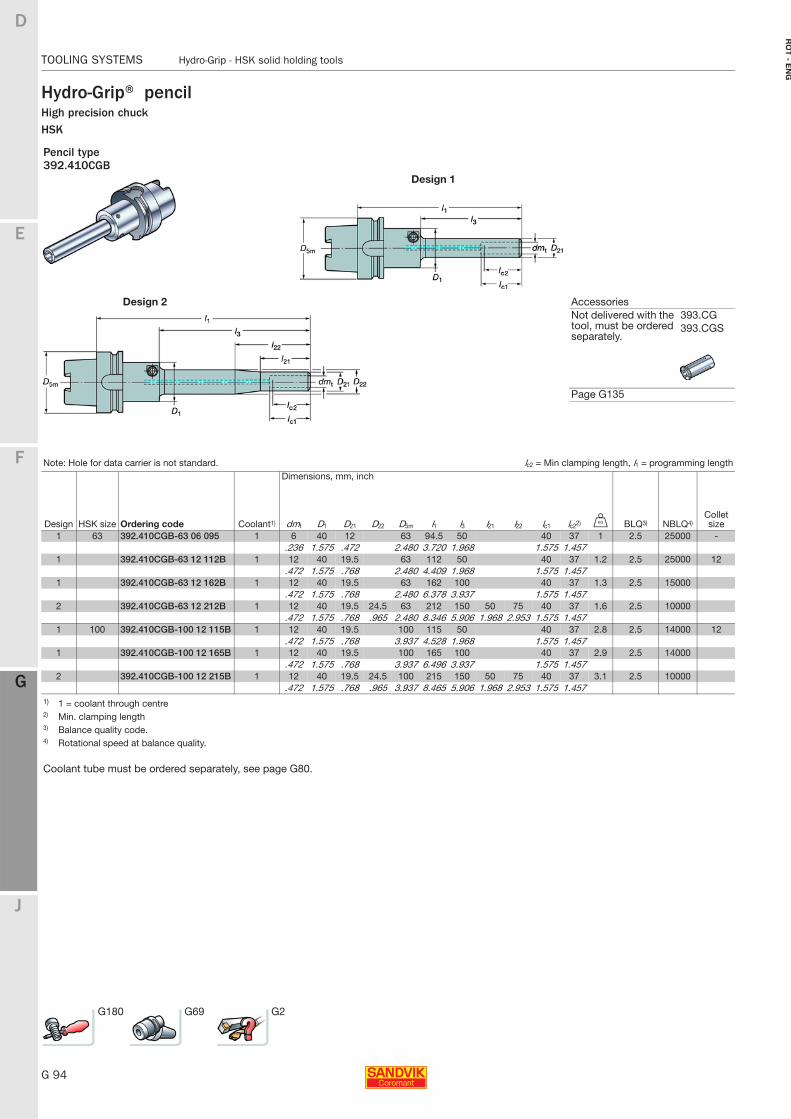
G 94
TOOLING SYSTEMS Hydro-Grip - HSK solid holding tools
E
F
G
J
D
G
RO
T - E
NG
TOOLING SYSTEMS Hydro-Grip - HSK solid holding tools
Hydro-Grip® pencilHigh precision chuckHSK
Pencil type392.410CGB
Design 1
Design 2 AccessoriesNot delivered with the tool, must be ordered separately.
393.CG393.CGS
Page G135
Note: Hole for data carrier is not standard. lc2 = Min clamping length, l1 = programming lengthDimensions, mm, inch
Design HSK size Ordering code Coolant1) dmt D1 D21 D22 D5m l1 l3 l21 l22 lc1 lc22) U BLQ3) NBLQ4)Collet size
1 63 392.410CGB-63 06 095 1 6 40 12 63 94.5 50 40 37 1 2.5 25000 -.236 1.575 .472 2.480 3.720 1.968 1.575 1.457
1 392.410CGB-63 12 112B 1 12 40 19.5 63 112 50 40 37 1.2 2.5 25000 12.472 1.575 .768 2.480 4.409 1.968 1.575 1.457
1 392.410CGB-63 12 162B 1 12 40 19.5 63 162 100 40 37 1.3 2.5 15000.472 1.575 .768 2.480 6.378 3.937 1.575 1.457
2 392.410CGB-63 12 212B 1 12 40 19.5 24.5 63 212 150 50 75 40 37 1.6 2.5 10000.472 1.575 .768 .965 2.480 8.346 5.906 1.968 2.953 1.575 1.457
1 100 392.410CGB-100 12 115B 1 12 40 19.5 100 115 50 40 37 2.8 2.5 14000 12.472 1.575 .768 3.937 4.528 1.968 1.575 1.457
1 392.410CGB-100 12 165B 1 12 40 19.5 100 165 100 40 37 2.9 2.5 14000.472 1.575 .768 3.937 6.496 3.937 1.575 1.457
2 392.410CGB-100 12 215B 1 12 40 19.5 24.5 100 215 150 50 75 40 37 3.1 2.5 10000.472 1.575 .768 .965 3.937 8.465 5.906 1.968 2.953 1.575 1.457
1) 1 = coolant through centre2) Min. clamping length3) Balance quality code.4) Rotational speed at balance quality.
Coolant tube must be ordered separately, see page G80.
G180 G69 G2
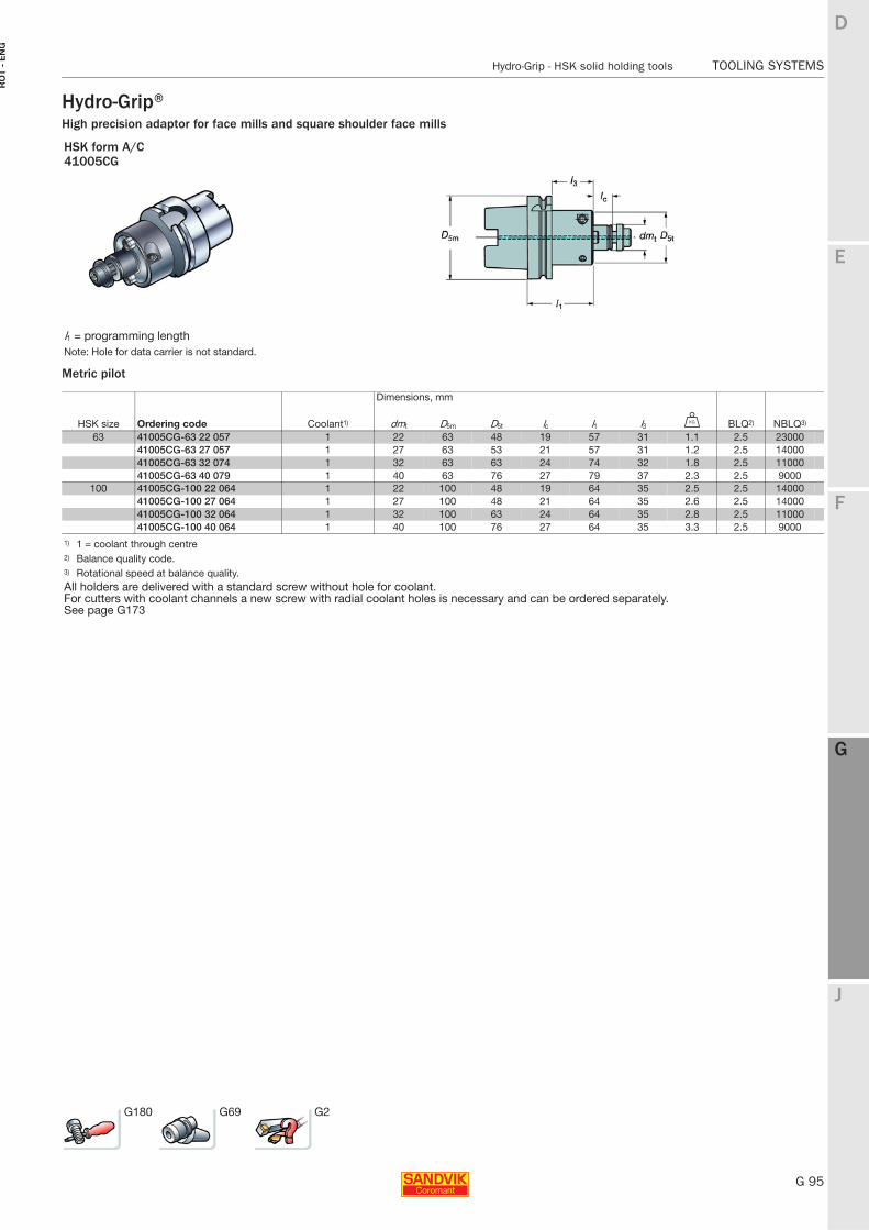
E
G 95
F
G
J
D
G
Hydro-Grip - HSK solid holding tools TOOLING SYSTEMS
RO
T -
EN
G
TOOLING SYSTEMS Hydro-Grip - HSK solid holding tools
Hydro-Grip®High precision adaptor for face mills and square shoulder face mills
Metric pilot
HSK form A/C41005CG
l1 = programming lengthNote: Hole for data carrier is not standard.
Dimensions, mm
HSK size Ordering code Coolant1) dmt D5m D5t lc l1 l3 U BLQ2) NBLQ3)
63 41005CG-63 22 057 1 22 63 48 19 57 31 1.1 2.5 2300041005CG-63 27 057 1 27 63 53 21 57 31 1.2 2.5 1400041005CG-63 32 074 1 32 63 63 24 74 32 1.8 2.5 1100041005CG-63 40 079 1 40 63 76 27 79 37 2.3 2.5 9000
100 41005CG-100 22 064 1 22 100 48 19 64 35 2.5 2.5 1400041005CG-100 27 064 1 27 100 48 21 64 35 2.6 2.5 1400041005CG-100 32 064 1 32 100 63 24 64 35 2.8 2.5 1100041005CG-100 40 064 1 40 100 76 27 64 35 3.3 2.5 9000
1) 1 = coolant through centre2) Balance quality code.3) Rotational speed at balance quality.All holders are delivered with a standard screw without hole for coolant.For cutters with coolant channels a new screw with radial coolant holes is necessary and can be ordered separately.See page G173
G180 G69 G2
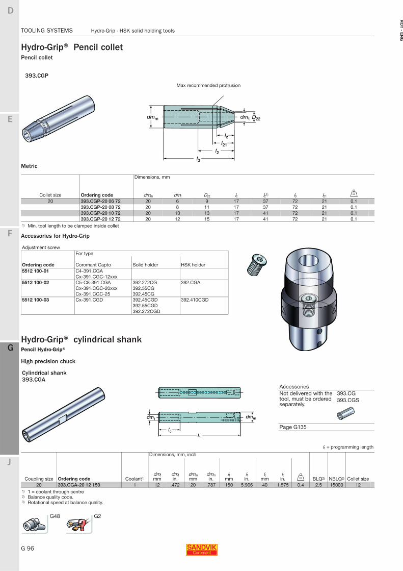
G 96
TOOLING SYSTEMS Hydro-Grip - HSK solid holding tools
E
F
G
J
D
G
RO
T - E
NG
TOOLING SYSTEMS Hydro-Grip - HSK solid holding tools
Hydro-Grip® Pencil colletPencil collet
Metric
Accessories for Hydro-Grip
Hydro-Grip® cylindrical shankPencil Hydro-Grip®
High precision chuck
393.CGP
Max recommended protrusion
Dimensions, mm
Collet size Ordering code dmm dmt D22 lc l21) l3 l21 U
20 393.CGP-20 06 72 20 6 9 17 37 72 21 0.1393.CGP-20 08 72 20 8 11 17 37 72 21 0.1393.CGP-20 10 72 20 10 13 17 41 72 21 0.1393.CGP-20 12 72 20 12 15 17 41 72 21 0.1
1) Min. tool length to be clamped inside collet
Adjustment screwFor type
Ordering code Coromant Capto Solid holder HSK holder5512 100-01 C4-391.CGA
Cx-391.CGC-12xxx5512 100-02 C5-C8-391.CGA 392.272CG 392.CGA
Cx-391.CGC-20xxx 392.55CGCx-391.CGC-25 392.45CG
5512 100-03 Cx-391.CGD 392.45CGD 392.410CGD392.55CGD392.272CGD
Cylindrical shank393.CGA
AccessoriesNot delivered with the tool, must be ordered separately.
393.CG393.CGS
Page G135
l1 = programming length
Dimensions, mm, inch
Coupling size Ordering code Coolant1)dmtmm
dmtin.
dmmmm
dmmin.
l1mm
l1in.
lcmm
lcin. U BLQ2) NBLQ3) Collet size
20 393.CGA-20 12 150 1 12 .472 20 .787 150 5.906 40 1.575 0.4 2.5 15000 121) 1 = coolant through centre2) Balance quality code.3) Rotational speed at balance quality.
G48 G2
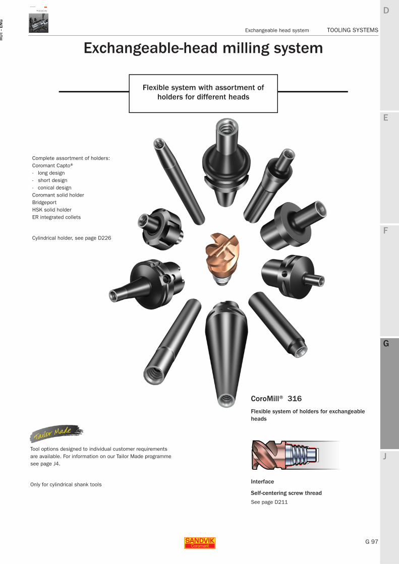
E
G 97
F
G
J
D
G
Exchangeable head system TOOLING SYSTEMS
RO
T -
EN
G
TOOLING SYSTEMS Exchangeable head system
Exchangeable-head milling system
Flexible system with assortment of holders for different heads
CoroMill® 316
Flexible system of holders for exchangeable heads
Interface
Self-centering screw thread
See page D211
Tool options designed to individual customer requirements are available. For information on our Tailor Made programme see page J4.
Only for cylindrical shank tools
Complete assortment of holders:Coromant Capto® - long design- short design- conical designCoromant solid holderBridgeportHSK solid holderER integrated collets
Cylindrical holder, see page D226
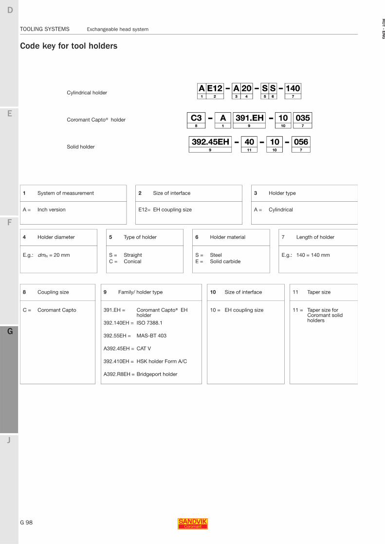
G 98
TOOLING SYSTEMS Exchangeable head system
E
F
G
J
D
G
RO
T - E
NG
TOOLING SYSTEMS Exchangeable head system
Code key for tool holders
Cylindrical holder
Coromant Capto® holder
Solid holder
1 System of measurement 2 Size of interface 3 Holder type
A = Inch version E12= EH coupling size A = Cylindrical
4 Holder diameter 5 Type of holder 6 Holder material 7 Length of holder
E.g.: dmm = 20 mm S = Straight S = Steel E.g.: 140 = 140 mmC = Conical E = Solid carbide
8 Coupling size 9 Family/ holder type 10 Size of interface 11 Taper size
C = Coromant Capto 391.EH = Coromant Capto® EH holder
10 = EH coupling size 11 = Taper size for Coromant solid holders392.140EH = ISO 7388.1
392.55EH = MAS-BT 403
A392.45EH = CAT V
392.410EH = HSK holder Form A/C
A392.R8EH = Bridgeport holder
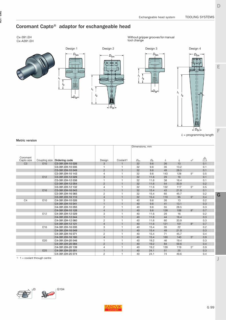
E
G 99
F
G
J
D
G
Exchangeable head system TOOLING SYSTEMS
RO
T -
EN
G
TOOLING SYSTEMS Exchangeable head system
Coromant Capto® adaptor for exchangeable head
Metric version
Cx-391.EH Without gripper grooves for manual tool changeCx-A391.EH
Design 1 Design 2 Design 3 Design 4
l1 = programming length
Dimensions, mm
CoromantCapto size Coupling size Ordering code Design Coolant1) D5m D5t l1 l3 α° U
C3 E10 C3-391.EH-10 026 3 1 32 9.6 26 13 0.1C3-391.EH-10 035 1 1 32 9.6 35 13.2 0.1C3-391.EH-10 049 2 1 32 9.6 49 28.5 0.1C3-391.EH-10 143 4 1 32 9.6 143 128 5° 0.5
E12 C3-391.EH-12 029 3 1 32 11.6 29 16 0.1C3-391.EH-12 038 1 1 32 11.6 38 16.4 0.1C3-391.EH-12 054 2 1 32 11.6 54 33.9 0.2C3-391.EH-12 132 4 1 32 11.6 132 117 5° 0.5
E16 C3-391.EH-16 043 1 1 32 15.4 43 21.9 0.1C3-391.EH-16 065 2 1 32 15.4 65 45.7 0.2C3-391.EH-16 110 4 1 32 15.4 110 95 5° 0.4
C4 E10 C4-391.EH-10 026 3 1 40 9.6 26 13 0.2C4-391.EH-10 041 1 1 40 9.6 41 13.1 0.3C4-391.EH-10 055 2 1 40 9.6 55 28.5 0.3C4-391.EH-10 128 4 1 40 9.6 128 108 8° 0.7
E12 C4-391.EH-12 029 3 1 40 11.6 29 16 0.2C4-391.EH-12 044 1 1 40 11.6 44 16.4 0.3C4-391.EH-12 060 2 1 40 11.6 60 33.9 0.3C4-391.EH-12 121 4 1 40 11.6 121 101 8° 0.7
E16 C4-391.EH-16 035 3 1 40 15.4 35 22 0.2C4-391.EH-16 049 1 1 40 15.4 49 21.9 0.3C4-391.EH-16 071 2 1 40 15.4 71 45.7 0.4C4-391.EH-16 160 4 1 40 15.4 160 140 5° 0.9
E20 C4-391.EH-20 046 1 1 40 19.2 46 19.4 0.3C4-391.EH-20 084 2 1 40 19.2 84 59.6 0.4C4-391.EH-20 139 4 1 40 19.2 139 119 5° 0.9
E25 C4-391.EH-25 051 1 1 40 24.1 51 25 0.3C4-391.EH-25 074 2 1 40 24.1 74 49.6 0.4
1) 1 = coolant through centre
J3 G104
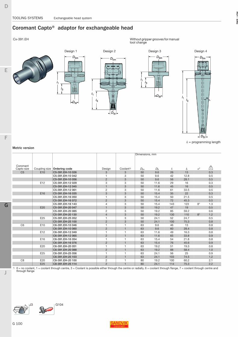
G 100
TOOLING SYSTEMS Exchangeable head system
E
F
G
J
D
G
RO
T - E
NG
TOOLING SYSTEMS Exchangeable head system
Coromant Capto® adaptor for exchangeable head
Metric version
Cx-391.EH Without gripper grooves for manual tool change
Design 1 Design 2 Design 3 Design 4
l1 = programming length
Dimensions, mm
CoromantCapto size Coupling size Ordering code Design Coolant1) D5m D5t l1 l3 α° U
C5 E10 C5-391.EH-10 026 3 3 50 9.6 26 13 0.3C5-391.EH-10 042 1 3 50 9.6 42 12.8 0.5C5-391.EH-10 056 2 3 50 9.6 56 28.1 0.5
E12 C5-391.EH-12 029 3 3 50 11.6 29 16 0.3C5-391.EH-12 045 1 3 50 11.6 45 16 0.5C5-391.EH-12 061 2 3 50 11.6 61 33.5 0.5
E16 C5-391.EH-16 035 3 3 50 15.4 35 22 0.3C5-391.EH-16 050 1 3 50 15.4 50 21.5 0.5C5-391.EH-16 072 2 3 50 15.4 72 45.3 0.5C5-391.EH-16 143 4 3 50 15.4 143 123 8° 1.3
E20 C5-391.EH-20 047 1 3 50 19.2 47 19 0.5C5-391.EH-20 085 2 3 50 19.2 85 59.2 0.6C5-391.EH-20 130 4 3 50 19.2 130 110 8° 1.2
E25 C5-391.EH-25 052 1 3 50 24.1 52 24.7 0.5C5-391.EH-25 100 2 3 50 24.1 100 75.3 0.8
C6 E10 C6-391.EH-10 046 1 1 63 9.6 46 13 0.8C6-391.EH-10 060 2 1 63 9.6 60 28.4 0.8
E12 C6-391.EH-12 049 1 1 63 11.6 49 16.3 0.8C6-391.EH-12 065 2 1 63 11.6 65 33.8 0.9
E16 C6-391.EH-16 054 1 1 63 15.4 54 21.8 0.8C6-391.EH-16 076 2 1 63 15.4 76 45.6 0.9
E20 C6-391.EH-20 051 1 1 63 19.2 51 19.3 0.8C6-391.EH-20 088 2 1 63 19.2 88 58.4 1.0
E25 C6-391.EH-25 056 1 1 63 24.1 56 25 0.9C6-391.EH-25 103 2 1 63 24.1 103 74.5 1.2
C8 E20 C8-391.EH-20 100 2 1 80 19.2 100 60.2 2.1E25 C8-391.EH-25 114 2 1 80 24.1 114 75.3 2.2
1) 0 = no coolant, 1 = coolant through centre, 3 = Coolant is possible either through the centre or radially, 6 = coolant through flange, 7 = coolant through centre and through flange
J3 G104
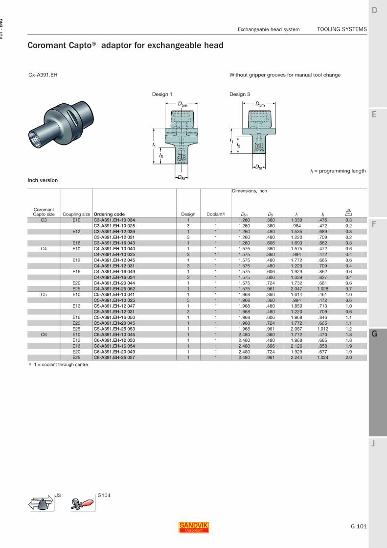
E
G 101
F
G
J
D
G
Exchangeable head system TOOLING SYSTEMS
RO
T -
EN
G
TOOLING SYSTEMS Exchangeable head system
Coromant Capto® adaptor for exchangeable head
Inch version
Cx-A391.EH Without gripper grooves for manual tool change
Design 1 Design 3
l1 = programming length
Dimensions, inch
CoromantCapto size Coupling size Ordering code Design Coolant1) D5m D5t l1 l3 V
C3 E10 C3-A391.EH-10 034 1 1 1.260 .360 1.339 .476 0.3C3-A391.EH-10 025 3 1 1.260 .360 .984 .472 0.2
E12 C3-A391.EH-12 039 1 1 1.260 .480 1.535 .689 0.3C3-A391.EH-12 031 3 1 1.260 .480 1.220 .709 0.2
E16 C3-A391.EH-16 043 1 1 1.260 .606 1.693 .862 0.3C4 E10 C4-A391.EH-10 040 1 1 1.575 .360 1.575 .472 0.6
C4-A391.EH-10 025 3 1 1.575 .360 .984 .472 0.4E12 C4-A391.EH-12 045 1 1 1.575 .480 1.772 .685 0.6
C4-A391.EH-12 031 3 1 1.575 .480 1.220 .709 0.4E16 C4-A391.EH-16 049 1 1 1.575 .606 1.929 .862 0.6
C4-A391.EH-16 034 3 1 1.575 .606 1.339 .827 0.4E20 C4-A391.EH-20 044 1 1 1.575 .724 1.732 .681 0.6E25 C4-A391.EH-25 052 1 1 1.575 .961 2.047 1.028 0.7
C5 E10 C5-A391.EH-10 041 1 1 1.968 .360 1.614 .461 1.0C5-A391.EH-10 025 3 1 1.968 .360 .984 .472 0.6
E12 C5-A391.EH-12 047 1 1 1.968 .480 1.850 .713 1.0C5-A391.EH-12 031 3 1 1.968 .480 1.220 .709 0.6
E16 C5-A391.EH-16 050 1 1 1.968 .606 1.968 .846 1.1E20 C5-A391.EH-20 045 1 1 1.968 .724 1.772 .665 1.1E25 C5-A391.EH-25 053 1 1 1.968 .961 2.087 1.012 1.2
C6 E10 C6-A391.EH-10 045 1 1 2.480 .360 1.772 .470 1.8E12 C6-A391.EH-12 050 1 1 2.480 .480 1.968 .685 1.8E16 C6-A391.EH-16 054 1 1 2.480 .606 2.126 .858 1.9E20 C6-A391.EH-20 049 1 1 2.480 .724 1.929 .677 1.9E25 C6-A391.EH-25 057 1 1 2.480 .961 2.244 1.024 2.0
1) 1 = coolant through centre
J3 G104
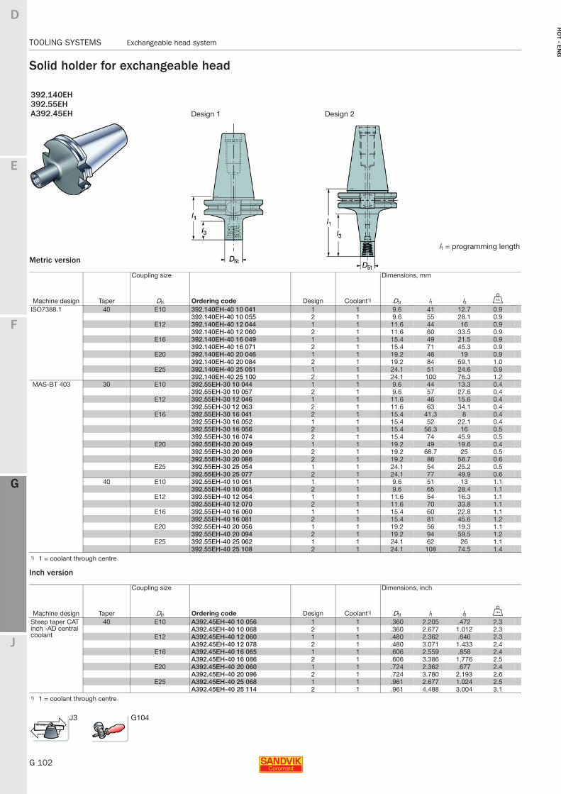
G 102
TOOLING SYSTEMS Exchangeable head system
E
F
G
J
D
G
RO
T - E
NG
TOOLING SYSTEMS Exchangeable head system
Solid holder for exchangeable head
Metric version
Inch version
392.140EH392.55EH A392.45EH Design 1 Design 2
l1 = programming length
Coupling size Dimensions, mm
Machine design Taper Dth Ordering code Design Coolant1) D5t l1 l3 U
ISO7388.1 40 E10 392.140EH-40 10 041 1 1 9.6 41 12.7 0.9392.140EH-40 10 055 2 1 9.6 55 28.1 0.9
E12 392.140EH-40 12 044 1 1 11.6 44 16 0.9392.140EH-40 12 060 2 1 11.6 60 33.5 0.9
E16 392.140EH-40 16 049 1 1 15.4 49 21.5 0.9392.140EH-40 16 071 2 1 15.4 71 45.3 0.9
E20 392.140EH-40 20 046 1 1 19.2 46 19 0.9392.140EH-40 20 084 2 1 19.2 84 59.1 1.0
E25 392.140EH-40 25 051 1 1 24.1 51 24.6 0.9392.140EH-40 25 100 2 1 24.1 100 76.3 1.2
MAS-BT 403 30 E10 392.55EH-30 10 044 1 1 9.6 44 13.3 0.4392.55EH-30 10 057 2 1 9.6 57 27.6 0.4
E12 392.55EH-30 12 046 1 1 11.6 46 15.6 0.4392.55EH-30 12 063 2 1 11.6 63 34.1 0.4
E16 392.55EH-30 16 041 2 1 15.4 41.3 8 0.4392.55EH-30 16 052 1 1 15.4 52 22.1 0.4392.55EH-30 16 056 2 1 15.4 56.3 16 0.5392.55EH-30 16 074 2 1 15.4 74 45.9 0.5
E20 392.55EH-30 20 049 1 1 19.2 49 19.6 0.4392.55EH-30 20 069 2 1 19.2 68.7 25 0.5392.55EH-30 20 086 2 1 19.2 86 58.7 0.6
E25 392.55EH-30 25 054 1 1 24.1 54 25.2 0.5392.55EH-30 25 077 2 1 24.1 77 49.9 0.6
40 E10 392.55EH-40 10 051 1 1 9.6 51 13 1.1392.55EH-40 10 065 2 1 9.6 65 28.4 1.1
E12 392.55EH-40 12 054 1 1 11.6 54 16.3 1.1392.55EH-40 12 070 2 1 11.6 70 33.8 1.1
E16 392.55EH-40 16 060 1 1 15.4 60 22.8 1.1392.55EH-40 16 081 2 1 15.4 81 45.6 1.2
E20 392.55EH-40 20 056 1 1 19.2 56 19.3 1.1392.55EH-40 20 094 2 1 19.2 94 59.5 1.2
E25 392.55EH-40 25 062 1 1 24.1 62 26 1.1392.55EH-40 25 108 2 1 24.1 108 74.5 1.4
1) 1 = coolant through centre
Coupling size Dimensions, inch
Machine design Taper Dth Ordering code Design Coolant1) D5t l1 l3 V
Steep taper CAT inch -AD central coolant
40 E10 A392.45EH-40 10 056 1 1 .360 2.205 .472 2.3A392.45EH-40 10 068 2 1 .360 2.677 1.012 2.3
E12 A392.45EH-40 12 060 1 1 .480 2.362 .646 2.3A392.45EH-40 12 078 2 1 .480 3.071 1.433 2.4
E16 A392.45EH-40 16 065 1 1 .606 2.559 .858 2.4A392.45EH-40 16 086 2 1 .606 3.386 1.776 2.5
E20 A392.45EH-40 20 060 1 1 .724 2.362 .677 2.4A392.45EH-40 20 096 2 1 .724 3.780 2.193 2.6
E25 A392.45EH-40 25 068 1 1 .961 2.677 1.024 2.5A392.45EH-40 25 114 2 1 .961 4.488 3.004 3.1
1) 1 = coolant through centre
J3 G104
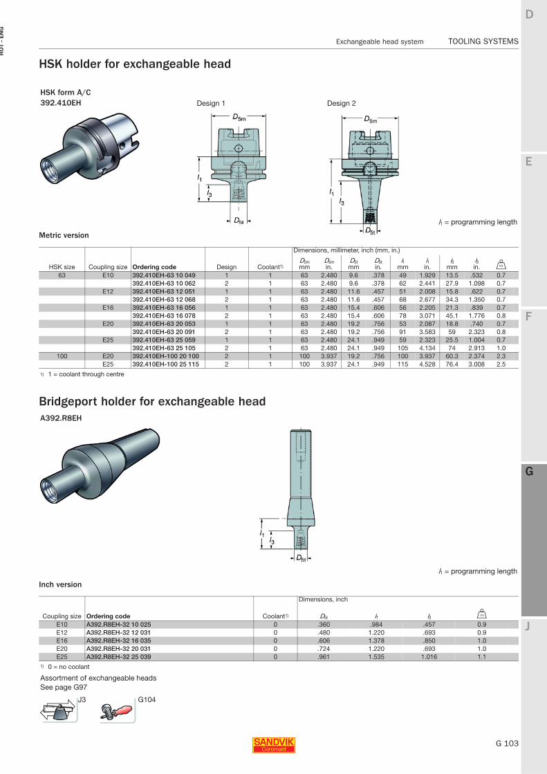
E
G 103
F
G
J
D
G
Exchangeable head system TOOLING SYSTEMS
RO
T -
EN
G
TOOLING SYSTEMS Exchangeable head system
HSK holder for exchangeable head
Metric version
Bridgeport holder for exchangeable head
Inch version
HSK form A/C392.410EH Design 1 Design 2
l1 = programming length
Dimensions, millimeter, inch (mm, in.)
HSK size Coupling size Ordering code Design Coolant1)D5mmm
D5min.
D5tmm
D5tin.
l1mm
l1in.
l3mm
l3in. U
63 E10 392.410EH-63 10 049 1 1 63 2.480 9.6 .378 49 1.929 13.5 .532 0.7392.410EH-63 10 062 2 1 63 2.480 9.6 .378 62 2.441 27.9 1.098 0.7
E12 392.410EH-63 12 051 1 1 63 2.480 11.6 .457 51 2.008 15.8 .622 0.7392.410EH-63 12 068 2 1 63 2.480 11.6 .457 68 2.677 34.3 1.350 0.7
E16 392.410EH-63 16 056 1 1 63 2.480 15.4 .606 56 2.205 21.3 .839 0.7392.410EH-63 16 078 2 1 63 2.480 15.4 .606 78 3.071 45.1 1.776 0.8
E20 392.410EH-63 20 053 1 1 63 2.480 19.2 .756 53 2.087 18.8 .740 0.7392.410EH-63 20 091 2 1 63 2.480 19.2 .756 91 3.583 59 2.323 0.8
E25 392.410EH-63 25 059 1 1 63 2.480 24.1 .949 59 2.323 25.5 1.004 0.7392.410EH-63 25 105 2 1 63 2.480 24.1 .949 105 4.134 74 2.913 1.0
100 E20 392.410EH-100 20 100 2 1 100 3.937 19.2 .756 100 3.937 60.3 2.374 2.3E25 392.410EH-100 25 115 2 1 100 3.937 24.1 .949 115 4.528 76.4 3.008 2.5
1) 1 = coolant through centre
A392.R8EH
l1 = programming length
Dimensions, inch
Coupling size Ordering code Coolant1) D5t l1 l3 V
E10 A392.R8EH-32 10 025 0 .360 .984 .457 0.9E12 A392.R8EH-32 12 031 0 .480 1.220 .693 0.9E16 A392.R8EH-32 16 035 0 .606 1.378 .850 1.0E20 A392.R8EH-32 20 031 0 .724 1.220 .693 1.0E25 A392.R8EH-32 25 039 0 .961 1.535 1.016 1.1
1) 0 = no coolant
Assortment of exchangeable headsSee page G97
J3 G104
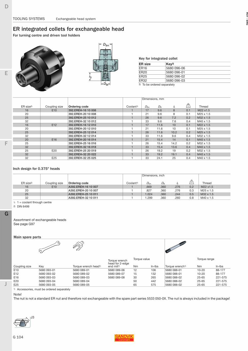
G 104
TOOLING SYSTEMS Exchangeable head system
E
F
G
J
D
G
RO
T - E
NG
TOOLING SYSTEMS Exchangeable head system
ER integrated collets for exchangeable headFor turning centre and driven tool holders
Inch design for 0.375" heads
Dimensions, mm
ER size2) Coupling size Ordering code Coolant1) D5m D5t l3 U Thread16 E10 392.EREH-16 10 008 1 17 9.6 8 0.1 M22 x1.520 392.EREH-20 10 008 1 21 9.6 8 0.1 M25 x 1.525 392.EREH-25 10 012 1 26 9.6 7.2 0.2 M32 x 1.532 392.EREH-32 10 012 1 33 9.6 7.6 0.4 M40 x 1.516 E12 392.EREH-16 12 010 1 17 11.6 10 0.1 M22 x 1.520 392.EREH-20 12 010 1 21 11.6 10 0.1 M25 x 1.525 392.EREH-25 12 014 1 26 11.6 10.2 0.2 M25 x 1.532 392.EREH-32 12 014 1 33 11.6 9.6 0.4 M32 x 1.520 E16 392.EREH-20 16 014 1 21 15.4 14 0.1 M40 x 1.525 392.EREH-25 16 016 1 26 15.4 14.2 0.2 M32 x 1.532 392.EREH-32 16 018 1 33 15.4 13.6 0.4 M40 x 1.525 E20 392.EREH-25 20 019 1 26 19.2 19 0.2 M32 x 1.532 392.EREH-32 20 022 1 33 19.2 19.1 0.4 M40 x 1.532 E25 392.EREH-32 25 025 1 33 24.1 25 0.4 M40 x 1.5
Dimensions, inch
ER size2) Coupling size Ordering code Coolant1) D5m D5t l3 V Thread16 E10 A392.EREH-16 10 007 1 .669 .360 .276 0.2 M22 x1.520 A392.EREH-20 10 007 1 .827 .360 .276 0.3 M25 x 1.525 A392.EREH-25 10 011 1 1.024 .360 .244 0.5 M32 x 1.532 A392.EREH-32 10 011 1 1.299 .360 .260 0.8 M40 x 1.5
1) 1 = coolant through centre2) DIN 6499
Assortment of exchangeable headsSee page G97
Main spare parts
Torque wrench head for 2-edge end mill1)
Torque value Torque range
Coupling size Key Torque wrench head1) Nm In-lbs Torque wrench1) Nm In-lbsE10 5680 093-01 5680 089-01 5680 089-06 12 106 5680 088-01 10-20 88-177E12 5680 093-02 5680 089-02 5680 089-07 15 132 5680 088-01 10-20 88-177E16 5680 093-03 5680 089-03 5680 089-08 30 265 5680 088-02 25-65 221-575E20 5680 093-04 5680 089-04 50 442 5680 088-02 25-65 221-575E25 5680 093-05 5680 089-05 65 575 5680 088-02 25-65 221-5751) Accessories, must be ordered separately
Note!The nut is not a standard ER nut and therefore not exchangeable with the spare part series 5533 050-0X. The nut is always included in the package!
J3
Key for integrated collet
ER size Key3)
ER16 5680 096-06ER20 5680 096-01ER25 5680 096-02ER32 5680 096-033) To be ordered separately
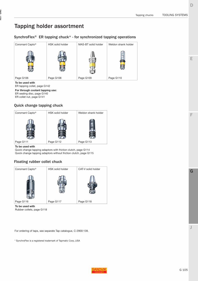
E
G 105
F
G
J
D
G
Tapping chucks TOOLING SYSTEMS
RO
T -
EN
G
TOOLING SYSTEMS Tapping chucks
SynchroFlex® ER tapping chuck* - for synchronized tapping operations
Quick change tapping chuck
Floating rubber collet chuck
Tapping holder assortment
Coromant Capto® HSK solid holder MAS-BT solid holder Weldon shank holder
Page G106 Page G108 Page G109 Page G110
To be used withER tapping collet, page G142
For through coolant tapping use:ER sealing disc, page G140ER collet nut, page G141
Coromant Capto® HSK solid holder Weldon shank holder
Page G111 Page G112 Page G113
To be used withQuick change tapping adaptors with friction clutch, page G114Quick change tapping adaptors without friction clutch, page G115
Coromant Capto® HSK solid holder CAT-V solid holder
Page G116 Page G117 Page G118
To be used withRubber collets, page G118
For ordering of taps, see separate Tap catalogue, C-2900:139.
* SynchroFlex is a registered trademark of Tapmatic Corp.,USA
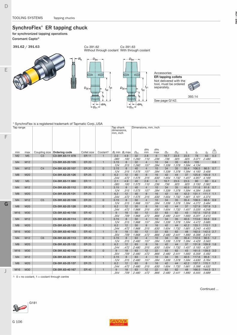
G 106
TOOLING SYSTEMS Tapping chucks
E
F
G
J
D
G
RO
T - E
NG
TOOLING SYSTEMS Tapping chucks
SynchroFlex® ER tapping chuckfor synchronized tapping operationsCoromant Capto®
391.62 / 391.63 Cx-391.62 Cx-391.63Without through coolant With through coolant
* SynchroFlex is a registered trademark of Tapmatic Corp.,USATap range Tap shank
dimensions, mm, inch
Dimensions, mm, inch
min max Coupling size Ordering code Collet size Coolant1) Bk min Bk max D5m
dmt min
dmt max D21 D22 l3 l21 l22 U
M2 M5 C3 C3-391.63-11 078 ER 11 1 2.0 4.9 32 2.8 6 18.7 23.5 23.5 78 63 0.3.083 .193 1.260 .110 .236 .736 .925 .925 3.071 2.480
M4 M12 C3-391.63-20 105 ER 20 1 3.15 8 32 4 10 34 35 40.5 105 0.6.124 .315 1.260 .157 .394 1.339 1.378 1.594 4.134
M4 M12 C4 C4-391.62-20 107 ER 20 0 3.15 8 40 4 10 34 35 35.4 106.5 86.5 0.7.124 .315 1.575 .157 .394 1.339 1.378 1.394 4.193 3.406
M8 M20 C4-391.62-25 126 ER 25 0 6.2 12 40 8 16 42 44 37 125.9 105.9 1.1.244 .472 1.575 .315 .630 1.654 1.732 1.457 4.957 4.169
M2 M5 C4-391.63-11 080 ER 11 1 2.1 4.9 40 2.8 6 18.7 23.5 23.5 80 60 0.4.083 .193 1.575 .110 .236 .736 .925 .925 3.150 2.362
M4 M12 C4-391.63-20 112 ER 20 1 3.15 8 40 4 10 34 35 40.5 111.6 91.6 0.7.124 .315 1.575 .157 .394 1.339 1.378 1.594 4.394 3.606
M8 M20 C4-391.63-25 131 ER 25 1 6.2 12 40 8 16 42 44 42.2 131.1 111.1 1.1.244 .472 1.575 .315 .630 1.654 1.732 1.661 5.161 4.374
M4 M12 C5 C5-391.62-20 109 ER 20 0 3.15 8 50 4 10 34 35 35.4 108.5 88.5 0.9.124 .315 1.968 .157 .394 1.339 1.378 1.394 4.272 3.484
M8 M20 C5-391.62-25 128 ER 25 0 6.2 12 50 8 16 42 44 37 127.9 107.9 1.3.244 .472 1.968 .315 .630 1.654 1.732 1.457 5.035 4.248
M16 M30 C5-391.62-40 158 ER 40 0 9 18 50 12 22 63 62 43 157.5 137.5 2.6.354 .709 1.968 .472 .866 2.480 2.441 1.693 6.201 5.413
M4 M12 C5-391.63-20 114 ER 20 1 3.15 8 50 4 10 34 35 40.5 113.6 93.6 0.9.124 .315 1.968 .157 .394 1.339 1.378 1.594 4.472 3.685
M8 M20 C5-391.63-25 133 ER 25 1 6.2 12 50 8 16 42 44 42.2 133.1 113.1 1.3.244 .472 1.968 .315 .630 1.654 1.732 1.661 5.240 4.453
M16 M30 C5-391.63-40 163 ER 40 1 9 18 50 12 22 63 62 48 162.5 142.5 2.7.354 .709 1.968 .472 .866 2.480 2.441 1.890 6.398 5.610
M4 M12 C6 C6-391.62-20 113 ER 20 0 3.15 8 63 4 10 34 35 35.4 112.5 90.5 1.2.124 .315 2.480 .157 .394 1.339 1.378 1.394 4.429 3.563
M8 M20 C6-391.62-25 132 ER 25 0 6.2 12 63 8 16 42 44 37 131.9 109.9 1.6.244 .472 2.480 .315 .630 1.654 1.732 1.457 5.193 4.327
M16 M30 C6-391.62-40 162 ER 40 0 9 18 63 12 22 63 62 43 161.5 139.5 3.0.354 .709 2.480 .472 .866 2.480 2.441 1.693 6.358 5.492
M4 M12 C6-391.63-20 118 ER 20 1 3.15 8 63 4 10 34 35 40.5 117.6 95.6 1.3.124 .315 2.480 .157 .394 1.339 1.378 1.594 4.630 3.764
M8 M20 C6-391.63-25 137 ER 25 1 6.2 12 63 8 16 42 44 42.2 137.1 115.1 1.7.244 .472 2.480 .315 .630 1.654 1.732 1.661 5.398 4.532
M16 M30 C6-391.63-40 167 ER 40 1 9 18 63 12 22 63 62 48 166.5 144.5 3.1.354 .709 2.480 .472 .866 2.480 2.441 1.890 6.555 5.689
1) 0 = no coolant, 1 = coolant through centre
Continued ...
AccessoriesER tapping colletsNot delivered with the tool, must be ordered separately.
393.14See page G142.
G181
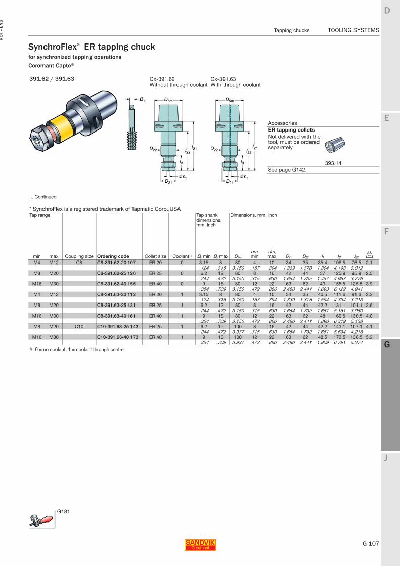
E
G 107
F
G
J
D
G
Tapping chucks TOOLING SYSTEMS
RO
T -
EN
G
TOOLING SYSTEMS Tapping chucks
SynchroFlex® ER tapping chuckfor synchronized tapping operationsCoromant Capto®
391.62 / 391.63 Cx-391.62 Cx-391.63Without through coolant With through coolant
... Continued
* SynchroFlex is a registered trademark of Tapmatic Corp.,USATap range Tap shank
dimensions, mm, inch
Dimensions, mm, inch
min max Coupling size Ordering code Collet size Coolant1) Bk min Bk max D5m
dmt min
dmt max D21 D22 l3 l21 l22 U
M4 M12 C8 C8-391.62-20 107 ER 20 0 3.15 8 80 4 10 34 35 35.4 106.5 76.5 2.1.124 .315 3.150 .157 .394 1.339 1.378 1.394 4.193 3.012
M8 M20 C8-391.62-25 126 ER 25 0 6.2 12 80 8 16 42 44 37 125.9 95.9 2.5.244 .472 3.150 .315 .630 1.654 1.732 1.457 4.957 3.776
M16 M30 C8-391.62-40 156 ER 40 0 9 18 80 12 22 63 62 43 155.5 125.5 3.9.354 .709 3.150 .472 .866 2.480 2.441 1.693 6.122 4.941
M4 M12 C8-391.63-20 112 ER 20 1 3.15 8 80 4 10 34 35 40.5 111.6 81.6 2.2.124 .315 3.150 .157 .394 1.339 1.378 1.594 4.394 3.213
M8 M20 C8-391.63-25 131 ER 25 1 6.2 12 80 8 16 42 44 42.2 131.1 101.1 2.6.244 .472 3.150 .315 .630 1.654 1.732 1.661 5.161 3.980
M16 M30 C8-391.63-40 161 ER 40 1 9 18 80 12 22 63 62 48 160.5 130.5 4.0.354 .709 3.150 .472 .866 2.480 2.441 1.890 6.319 5.138
M8 M20 C10 C10-391.63-25 143 ER 25 1 6.2 12 100 8 16 42 44 42.2 143.1 107.1 4.1.244 .472 3.937 .315 .630 1.654 1.732 1.661 5.634 4.216
M16 M30 C10-391.63-40 173 ER 40 1 9 18 100 12 22 63 62 48.5 172.5 136.5 5.2.354 .709 3.937 .472 .866 2.480 2.441 1.909 6.791 5.374
1) 0 = no coolant, 1 = coolant through centre
AccessoriesER tapping colletsNot delivered with the tool, must be ordered separately.
393.14See page G142.
G181
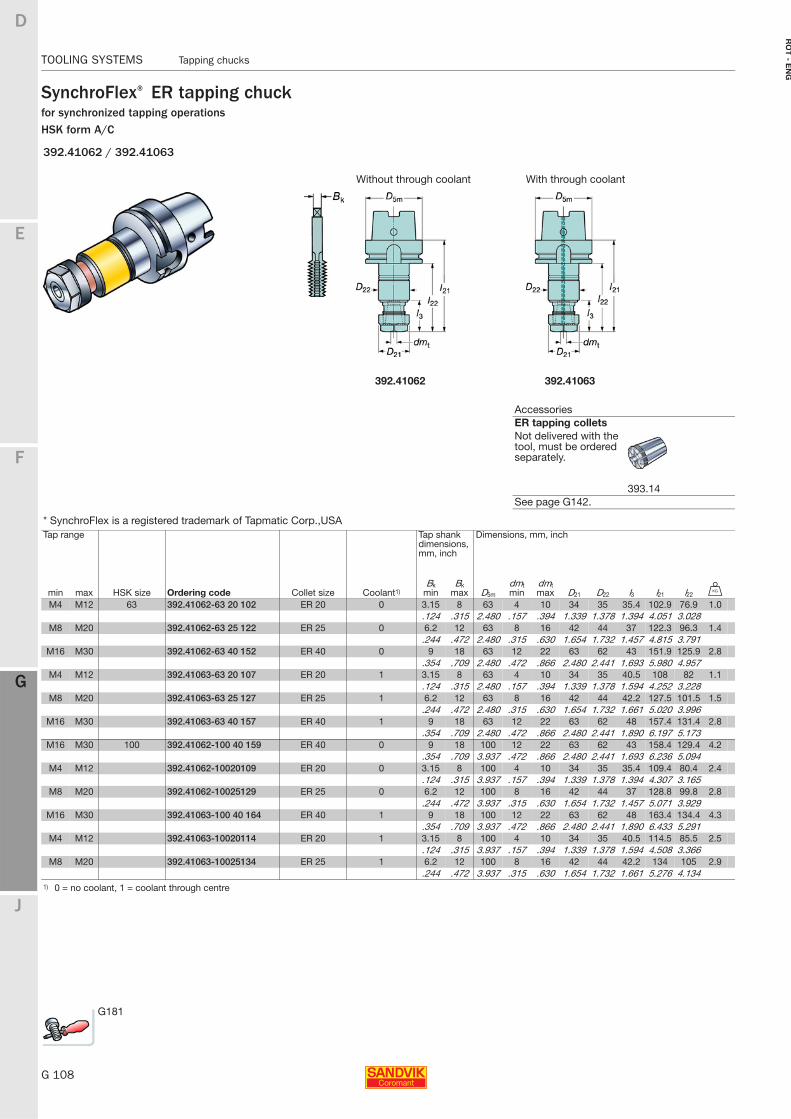
G 108
TOOLING SYSTEMS Tapping chucks
E
F
G
J
D
G
RO
T - E
NG
TOOLING SYSTEMS Tapping chucks
SynchroFlex® ER tapping chuckfor synchronized tapping operationsHSK form A/C
392.41062 / 392.41063
Without through coolant With through coolant
392.41062 392.41063
* SynchroFlex is a registered trademark of Tapmatic Corp.,USATap range Tap shank
dimensions, mm, inch
Dimensions, mm, inch
min max HSK size Ordering code Collet size Coolant1)Bk
minBk
max D5m
dmt min
dmt max D21 D22 l3 l21 l22 U
M4 M12 63 392.41062-63 20 102 ER 20 0 3.15 8 63 4 10 34 35 35.4 102.9 76.9 1.0.124 .315 2.480 .157 .394 1.339 1.378 1.394 4.051 3.028
M8 M20 392.41062-63 25 122 ER 25 0 6.2 12 63 8 16 42 44 37 122.3 96.3 1.4.244 .472 2.480 .315 .630 1.654 1.732 1.457 4.815 3.791
M16 M30 392.41062-63 40 152 ER 40 0 9 18 63 12 22 63 62 43 151.9 125.9 2.8.354 .709 2.480 .472 .866 2.480 2.441 1.693 5.980 4.957
M4 M12 392.41063-63 20 107 ER 20 1 3.15 8 63 4 10 34 35 40.5 108 82 1.1.124 .315 2.480 .157 .394 1.339 1.378 1.594 4.252 3.228
M8 M20 392.41063-63 25 127 ER 25 1 6.2 12 63 8 16 42 44 42.2 127.5 101.5 1.5.244 .472 2.480 .315 .630 1.654 1.732 1.661 5.020 3.996
M16 M30 392.41063-63 40 157 ER 40 1 9 18 63 12 22 63 62 48 157.4 131.4 2.8.354 .709 2.480 .472 .866 2.480 2.441 1.890 6.197 5.173
M16 M30 100 392.41062-100 40 159 ER 40 0 9 18 100 12 22 63 62 43 158.4 129.4 4.2.354 .709 3.937 .472 .866 2.480 2.441 1.693 6.236 5.094
M4 M12 392.41062-10020109 ER 20 0 3.15 8 100 4 10 34 35 35.4 109.4 80.4 2.4.124 .315 3.937 .157 .394 1.339 1.378 1.394 4.307 3.165
M8 M20 392.41062-10025129 ER 25 0 6.2 12 100 8 16 42 44 37 128.8 99.8 2.8.244 .472 3.937 .315 .630 1.654 1.732 1.457 5.071 3.929
M16 M30 392.41063-100 40 164 ER 40 1 9 18 100 12 22 63 62 48 163.4 134.4 4.3.354 .709 3.937 .472 .866 2.480 2.441 1.890 6.433 5.291
M4 M12 392.41063-10020114 ER 20 1 3.15 8 100 4 10 34 35 40.5 114.5 85.5 2.5.124 .315 3.937 .157 .394 1.339 1.378 1.594 4.508 3.366
M8 M20 392.41063-10025134 ER 25 1 6.2 12 100 8 16 42 44 42.2 134 105 2.9.244 .472 3.937 .315 .630 1.654 1.732 1.661 5.276 4.134
1) 0 = no coolant, 1 = coolant through centre
AccessoriesER tapping colletsNot delivered with the tool, must be ordered separately.
393.14See page G142.
G181
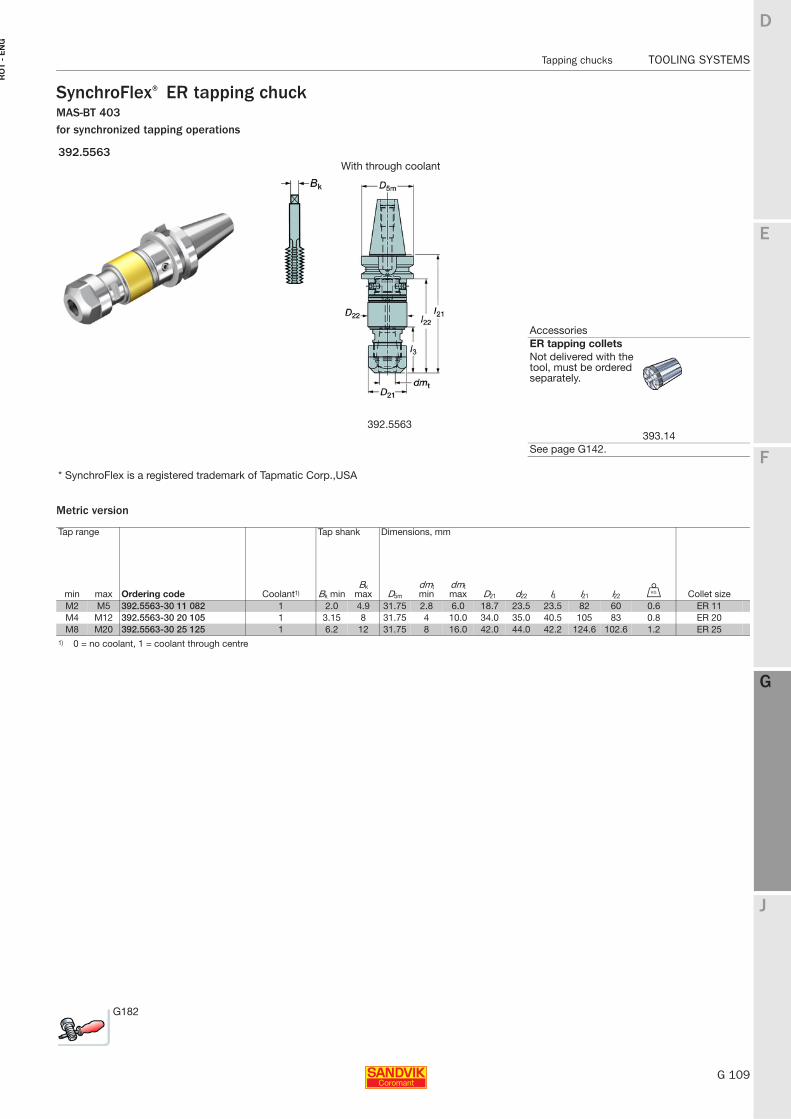
E
G 109
F
G
J
D
G
Tapping chucks TOOLING SYSTEMS
RO
T -
EN
G
TOOLING SYSTEMS Tapping chucks
SynchroFlex® ER tapping chuckMAS-BT 403for synchronized tapping operations
Metric version
392.5563With through coolant
* SynchroFlex is a registered trademark of Tapmatic Corp.,USA
Tap range Tap shank Dimensions, mm
min max Ordering code Coolant1) Bk minBk
max D5m
dmt min
dmt max D21 d22 l3 l21 l22 U Collet size
M2 M5 392.5563-30 11 082 1 2.0 4.9 31.75 2.8 6.0 18.7 23.5 23.5 82 60 0.6 ER 11M4 M12 392.5563-30 20 105 1 3.15 8 31.75 4 10.0 34.0 35.0 40.5 105 83 0.8 ER 20M8 M20 392.5563-30 25 125 1 6.2 12 31.75 8 16.0 42.0 44.0 42.2 124.6 102.6 1.2 ER 25
1) 0 = no coolant, 1 = coolant through centre
G182
AccessoriesER tapping colletsNot delivered with the tool, must be ordered separately.
393.14See page G142.
392.5563
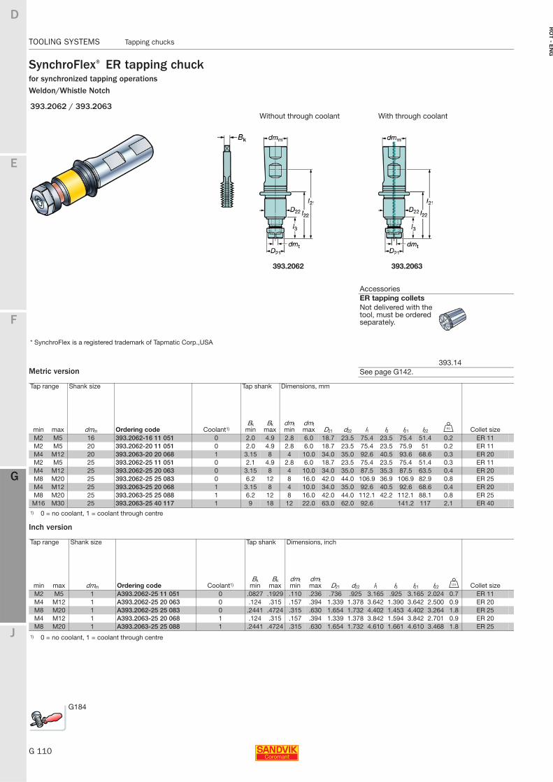
G 110
TOOLING SYSTEMS Tapping chucks
E
F
G
J
D
G
RO
T - E
NG
TOOLING SYSTEMS Tapping chucks
SynchroFlex® ER tapping chuckfor synchronized tapping operationsWeldon/Whistle Notch
Metric version
Inch version
393.2062 / 393.2063Without through coolant With through coolant
393.2062 393.2063
* SynchroFlex is a registered trademark of Tapmatic Corp.,USA
Tap range Shank size Tap shank Dimensions, mm
min max dmm Ordering code Coolant1)Bk
minBk
maxdmt min
dmt max D21 d22 l1 l3 l21 l22 U Collet size
M2 M5 16 393.2062-16 11 051 0 2.0 4.9 2.8 6.0 18.7 23.5 75.4 23.5 75.4 51.4 0.2 ER 11M2 M5 20 393.2062-20 11 051 0 2.0 4.9 2.8 6.0 18.7 23.5 75.4 23.5 75.9 51 0.2 ER 11M4 M12 20 393.2063-20 20 068 1 3.15 8 4 10.0 34.0 35.0 92.6 40.5 93.6 68.6 0.3 ER 20M2 M5 25 393.2062-25 11 051 0 2.1 4.9 2.8 6.0 18.7 23.5 75.4 23.5 75.4 51.4 0.3 ER 11M4 M12 25 393.2062-25 20 063 0 3.15 8 4 10.0 34.0 35.0 87.5 35.3 87.5 63.5 0.4 ER 20M8 M20 25 393.2062-25 25 083 0 6.2 12 8 16.0 42.0 44.0 106.9 36.9 106.9 82.9 0.8 ER 25M4 M12 25 393.2063-25 20 068 1 3.15 8 4 10.0 34.0 35.0 92.6 40.5 92.6 68.6 0.4 ER 20M8 M20 25 393.2063-25 25 088 1 6.2 12 8 16.0 42.0 44.0 112.1 42.2 112.1 88.1 0.8 ER 25M16 M30 25 393.2063-25 40 117 1 9 18 12 22.0 63.0 62.0 92.6 141.2 117 2.1 ER 40
1) 0 = no coolant, 1 = coolant through centre
Tap range Shank size Tap shank Dimensions, inch
min max dmm Ordering code Coolant1)Bk
minBk
maxdmt min
dmt max D21 d22 l1 l3 l21 l22 V Collet size
M2 M5 1 A393.2062-25 11 051 0 .0827 .1929 .110 .236 .736 .925 3.165 .925 3.165 2.024 0.7 ER 11M4 M12 1 A393.2062-25 20 063 0 .124 .315 .157 .394 1.339 1.378 3.642 1.390 3.642 2.500 0.9 ER 20M8 M20 1 A393.2062-25 25 083 0 .2441 .4724 .315 .630 1.654 1.732 4.402 1.453 4.402 3.264 1.8 ER 25M4 M12 1 A393.2063-25 20 068 1 .124 .315 .157 .394 1.339 1.378 3.842 1.594 3.842 2.701 0.9 ER 20M8 M20 1 A393.2063-25 25 088 1 .2441 .4724 .315 .630 1.654 1.732 4.610 1.661 4.610 3.468 1.8 ER 25
1) 0 = no coolant, 1 = coolant through centre
AccessoriesER tapping colletsNot delivered with the tool, must be ordered separately.
393.14See page G142.
G184
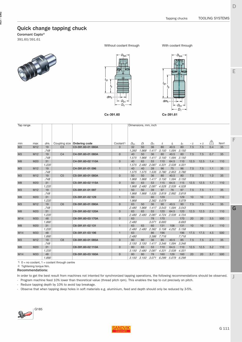
E
G 111
F
G
J
D
G
Tapping chucks TOOLING SYSTEMS
RO
T -
EN
G
TOOLING SYSTEMS Tapping chucks
Quick change tapping chuckCoromant Capto® 391.60/391.61
Without coolant through With coolant through
Cx-391.60 Cx-391.61
Tap range Dimensions, mm, inch
min max dmt Coupling size Ordering code Coolant1) D5m D1 D21 l1 l3 l21 - z + z U Nm2)
M3 M12 19 C3 C3-391.60-01 080A 0 32 50 36 80 40.5 80 7.5 7.5 0.4 35.748 1.260 1.968 1.417 3.150 1.594 3.150
M3 M12 19 C4 C4-391.60-01 080A 0 40 50 36 80 40.5 80 7.5 7.5 0.7 35.748 1.575 1.968 1.417 3.150 1.594 3.150
M8 M20 31 C4-391.60-02 110A 0 40 63 53 110 64.5 110 12.5 12.5 1.4 1101.220 1.575 2.480 2.087 4.331 2.539 4.331
M3 M12 19 C4-391.61-01 096 1 40 40 39 96 75 96 7.5 7.5 1.1 35.748 1.575 1.575 1.535 3.780 2.953 3.780
M3 M12 19 C5 C5-391.60-01 080A 0 50 50 36 80 40.5 80 7.5 7.5 1.0 35.748 1.968 1.968 1.417 3.150 1.594 3.150
M8 M20 31 C5-391.60-02 115A 0 50 63 53 115 64.5 115 12.5 12.5 1.7 1101.220 1.968 2.480 2.087 4.528 2.539 4.528
M3 M12 19 C5-391.61-01 097 1 50 50 39 97 76 97 7.5 7.5 1.1 35.748 1.968 1.968 1.535 3.819 2.992 3.819
M8 M20 31 C5-391.61-02 129 1 50 60 129 129 10 10 2.1 1101.220 1.968 2.362 5.079 5.079
M3 M12 19 C6 C6-391.60-01 090A 0 63 50 36 90 40.5 90 7.5 7.5 1.4 35.748 2.480 1.968 1.417 3.543 1.594 3.543
M8 M20 31 C6-391.60-02 120A 0 63 63 53 120 64.5 120 12.5 12.5 2.3 1101.220 2.480 2.480 2.087 4.724 2.539 4.724
M14 M33 48 C6-391.60-03 170A 0 63 78 170 170 20 20 3.5 5001.890 2.480 3.071 6.693 6.693
M8 M20 31 C6-391.61-02 131 1 63 63 60 131 108 131 10 10 2.4 1101.220 2.480 2.480 2.362 5.158 4.252 5.158
M14 M33 48 C6-391.61-03 196 1 63 86 196 196 17.5 17.5 4.5 5001.890 2.480 3.386 7.716 7.716
M3 M12 19 C8 C8-391.60-01 085A 0 80 80 36 85 40.5 85 7.5 7.5 2.3 35.748 3.150 3.150 1.417 3.346 1.594 3.346
M8 M20 31 C8-391.60-02 110A 0 80 63 53 110 64.5 110 12.5 12.5 3.2 1101.220 3.150 2.480 2.087 4.331 2.539 4.331
M14 M33 48 C8-391.60-03 160A 0 80 80 78 160 129 160 20 20 3.7 5001.890 3.150 3.150 3.071 6.299 5.079 6.299
1) 0 = no coolant, 1 = coolant through centre2) Tightening torque Nm.
G185
Recommendations:
In order to get the best result from machines not intented for synchronized tapping operations, the following recommendations should be observed.- Program machine feed 10% lower than theoretical value (thread pitch rpm). This enables the tap to cut precisely on pitch.- Reduce tapping depth by 10% to avoid tap breakage.- Observe that when tapping deep holes in soft materials e.g. aluminium, feed and depth should only be reduced by 3-5%.
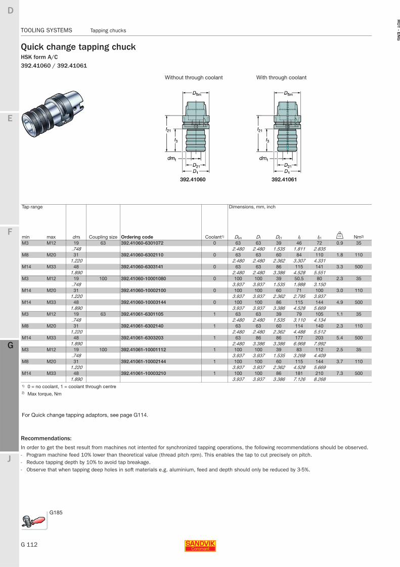
G 112
TOOLING SYSTEMS Tapping chucks
E
F
G
J
D
G
RO
T - E
NG
TOOLING SYSTEMS Tapping chucks
Quick change tapping chuckHSK form A/C
Recommendations:
In order to get the best result from machines not intented for synchronized tapping operations, the following recommendations should be observed.- Program machine feed 10% lower than theoretical value (thread pitch rpm). This enables the tap to cut precisely on pitch.- Reduce tapping depth by 10% to avoid tap breakage.- Observe that when tapping deep holes in soft materials e.g. aluminium, feed and depth should only be reduced by 3-5%.
392.41060 / 392.41061
Without through coolant With through coolant
392.41060 392.41061
Tap range Dimensions, mm, inch
min max dmt Coupling size Ordering code Coolant1) D5m D1 D21 l3 l21 U Nm2)
M3 M12 19 63 392.41060-6301072 0 63 63 39 46 72 0.9 35.748 2.480 2.480 1.535 1.811 2.835
M8 M20 31 392.41060-6302110 0 63 63 60 84 110 1.8 1101.220 2.480 2.480 2.362 3.307 4.331
M14 M33 48 392.41060-6303141 0 63 63 86 115 141 3.3 5001.890 2.480 2.480 3.386 4.528 5.551
M3 M12 19 100 392.41060-10001080 0 100 100 39 50.5 80 2.3 35.748 3.937 3.937 1.535 1.988 3.150
M14 M20 31 392.41060-10002100 0 100 100 60 71 100 3.0 1101.220 3.937 3.937 2.362 2.795 3.937
M14 M33 48 392.41060-10003144 0 100 100 86 115 144 4.9 5001.890 3.937 3.937 3.386 4.528 5.669
M3 M12 19 63 392.41061-6301105 1 63 63 39 79 105 1.1 35.748 2.480 2.480 1.535 3.110 4.134
M8 M20 31 392.41061-6302140 1 63 63 60 114 140 2.3 1101.220 2.480 2.480 2.362 4.488 5.512
M14 M33 48 392.41061-6303203 1 63 86 86 177 203 5.4 5001.890 2.480 3.386 3.386 6.968 7.992
M3 M12 19 100 392.41061-10001112 1 100 100 39 83 112 2.5 35.748 3.937 3.937 1.535 3.268 4.409
M8 M20 31 392.41061-10002144 1 100 100 60 115 144 3.7 1101.220 3.937 3.937 2.362 4.528 5.669
M14 M33 48 392.41061-10003210 1 100 100 86 181 210 7.3 5001.890 3.937 3.937 3.386 7.126 8.268
1) 0 = no coolant, 1 = coolant through centre2) Max torque, Nm
For Quick change tapping adaptors, see page G114.
G185
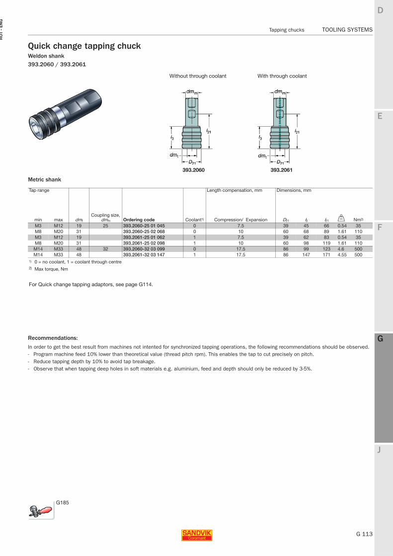
E
G 113
F
G
J
D
G
Tapping chucks TOOLING SYSTEMS
RO
T -
EN
G
TOOLING SYSTEMS Tapping chucks
Quick change tapping chuckWeldon shank393.2060 / 393.2061
Metric shank
Without through coolant With through coolant
393.2060 393.2061
Tap range Length compensation, mm Dimensions, mm
min max dmt
Coupling size, dmm Ordering code Coolant1) Compression/ Expansion D21 l3 l21 U Nm2)
M3 M12 19 25 393.2060-25 01 045 0 7.5 39 45 66 0.54 35M8 M20 31 393.2060-25 02 068 0 10 60 68 89 1.61 110M3 M12 19 393.2061-25 01 062 1 7.5 39 62 83 0.54 35M8 M20 31 393.2061-25 02 098 1 10 60 98 119 1.61 110
M14 M33 48 32 393.2060-32 03 099 0 17.5 86 99 123 4.6 500M14 M33 48 393.2061-32 03 147 1 17.5 86 147 171 4.55 500
1) 0 = no coolant, 1 = coolant through centre2) Max torque, Nm
For Quick change tapping adaptors, see page G114.
Recommendations:
In order to get the best result from machines not intented for synchronized tapping operations, the following recommendations should be observed.- Program machine feed 10% lower than theoretical value (thread pitch rpm). This enables the tap to cut precisely on pitch.- Reduce tapping depth by 10% to avoid tap breakage.- Observe that when tapping deep holes in soft materials e.g. aluminium, feed and depth should only be reduced by 3-5%.
G185
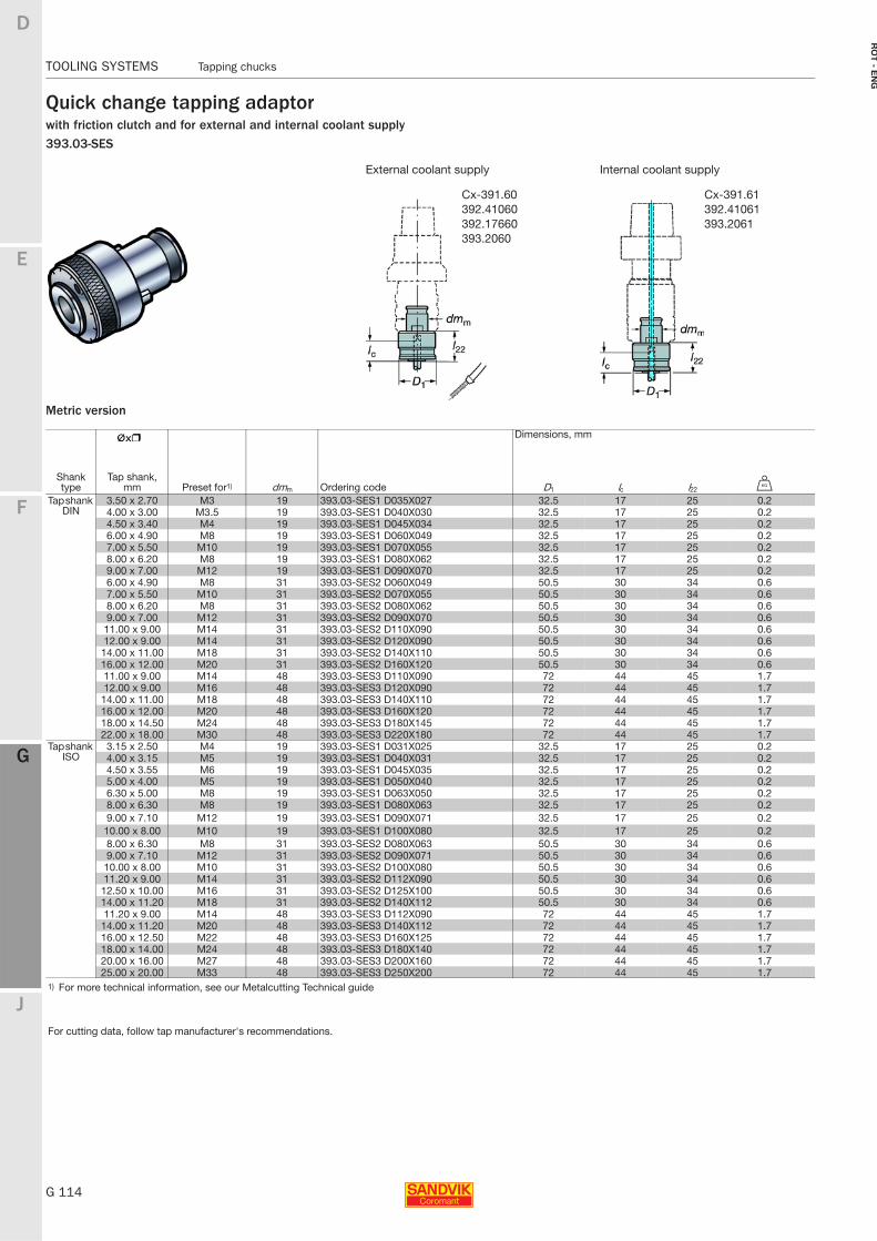
G 114
TOOLING SYSTEMS Tapping chucks
E
F
G
J
D
G
RO
T - E
NG
TOOLING SYSTEMS Tapping chucks
Quick change tapping adaptorwith friction clutch and for external and internal coolant supply393.03-SES
Metric version
External coolant supply Internal coolant supply
Dimensions, mm
Shank type
Tap shank, mm Preset for1) dmm Ordering code D1 lc l22 U
Tap shank DIN
3.50 x 2.70 M3 19 393.03-SES1 D035X027 32.5 17 25 0.24.00 x 3.00 M3.5 19 393.03-SES1 D040X030 32.5 17 25 0.24.50 x 3.40 M4 19 393.03-SES1 D045X034 32.5 17 25 0.26.00 x 4.90 M8 19 393.03-SES1 D060X049 32.5 17 25 0.27.00 x 5.50 M10 19 393.03-SES1 D070X055 32.5 17 25 0.28.00 x 6.20 M8 19 393.03-SES1 D080X062 32.5 17 25 0.29.00 x 7.00 M12 19 393.03-SES1 D090X070 32.5 17 25 0.26.00 x 4.90 M8 31 393.03-SES2 D060X049 50.5 30 34 0.67.00 x 5.50 M10 31 393.03-SES2 D070X055 50.5 30 34 0.68.00 x 6.20 M8 31 393.03-SES2 D080X062 50.5 30 34 0.69.00 x 7.00 M12 31 393.03-SES2 D090X070 50.5 30 34 0.611.00 x 9.00 M14 31 393.03-SES2 D110X090 50.5 30 34 0.612.00 x 9.00 M14 31 393.03-SES2 D120X090 50.5 30 34 0.6
14.00 x 11.00 M18 31 393.03-SES2 D140X110 50.5 30 34 0.616.00 x 12.00 M20 31 393.03-SES2 D160X120 50.5 30 34 0.611.00 x 9.00 M14 48 393.03-SES3 D110X090 72 44 45 1.712.00 x 9.00 M16 48 393.03-SES3 D120X090 72 44 45 1.7
14.00 x 11.00 M18 48 393.03-SES3 D140X110 72 44 45 1.716.00 x 12.00 M20 48 393.03-SES3 D160X120 72 44 45 1.718.00 x 14.50 M24 48 393.03-SES3 D180X145 72 44 45 1.722.00 x 18.00 M30 48 393.03-SES3 D220X180 72 44 45 1.7
Tap shank ISO
3.15 x 2.50 M4 19 393.03-SES1 D031X025 32.5 17 25 0.24.00 x 3.15 M5 19 393.03-SES1 D040X031 32.5 17 25 0.24.50 x 3.55 M6 19 393.03-SES1 D045X035 32.5 17 25 0.25.00 x 4.00 M5 19 393.03-SES1 D050X040 32.5 17 25 0.26.30 x 5.00 M8 19 393.03-SES1 D063X050 32.5 17 25 0.28.00 x 6.30 M8 19 393.03-SES1 D080X063 32.5 17 25 0.29.00 x 7.10 M12 19 393.03-SES1 D090X071 32.5 17 25 0.210.00 x 8.00 M10 19 393.03-SES1 D100X080 32.5 17 25 0.28.00 x 6.30 M8 31 393.03-SES2 D080X063 50.5 30 34 0.69.00 x 7.10 M12 31 393.03-SES2 D090X071 50.5 30 34 0.610.00 x 8.00 M10 31 393.03-SES2 D100X080 50.5 30 34 0.611.20 x 9.00 M14 31 393.03-SES2 D112X090 50.5 30 34 0.6
12.50 x 10.00 M16 31 393.03-SES2 D125X100 50.5 30 34 0.614.00 x 11.20 M18 31 393.03-SES2 D140X112 50.5 30 34 0.611.20 x 9.00 M14 48 393.03-SES3 D112X090 72 44 45 1.7
14.00 x 11.20 M20 48 393.03-SES3 D140X112 72 44 45 1.716.00 x 12.50 M22 48 393.03-SES3 D160X125 72 44 45 1.718.00 x 14.00 M24 48 393.03-SES3 D180X140 72 44 45 1.720.00 x 16.00 M27 48 393.03-SES3 D200X160 72 44 45 1.725.00 x 20.00 M33 48 393.03-SES3 D250X200 72 44 45 1.7
1) For more technical information, see our Metalcutting Technical guide
For cutting data, follow tap manufacturer's recommendations.
Cx-391.61392.41061393.2061
Cx-391.60392.41060392.17660393.2060
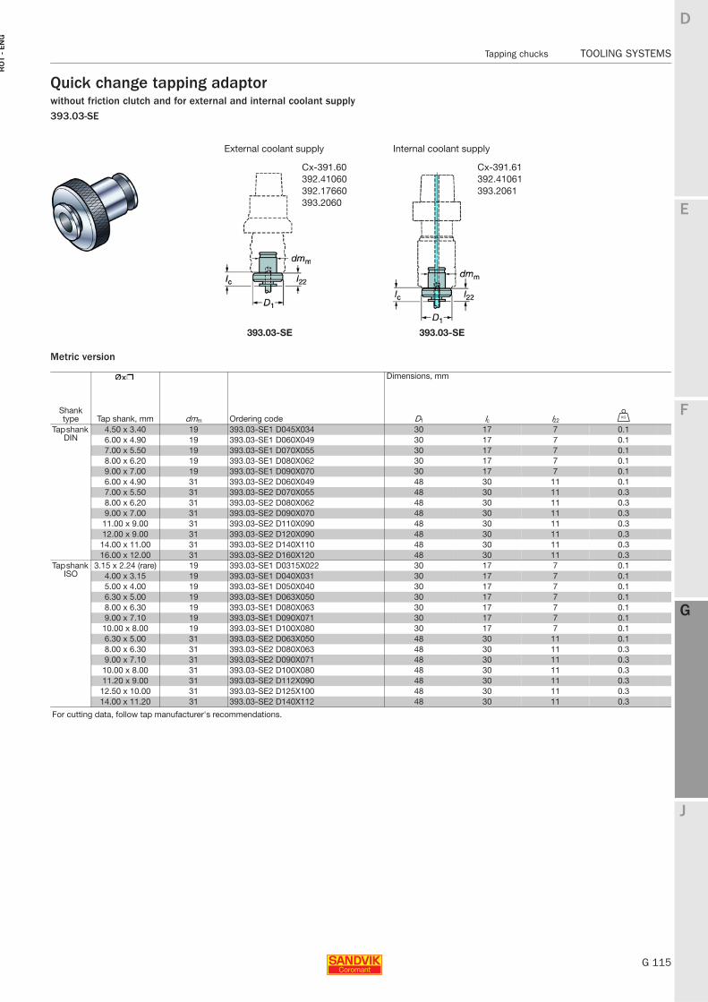
E
G 115
F
G
J
D
G
Tapping chucks TOOLING SYSTEMS
RO
T -
EN
G
TOOLING SYSTEMS Tapping chucks
Quick change tapping adaptorwithout friction clutch and for external and internal coolant supply393.03-SE
Metric version
External coolant supply Internal coolant supply
393.03-SE 393.03-SE
Dimensions, mm
Shank type Tap shank, mm dmm Ordering code D1 lc l22 U
Tap shank DIN
4.50 x 3.40 19 393.03-SE1 D045X034 30 17 7 0.16.00 x 4.90 19 393.03-SE1 D060X049 30 17 7 0.17.00 x 5.50 19 393.03-SE1 D070X055 30 17 7 0.18.00 x 6.20 19 393.03-SE1 D080X062 30 17 7 0.19.00 x 7.00 19 393.03-SE1 D090X070 30 17 7 0.16.00 x 4.90 31 393.03-SE2 D060X049 48 30 11 0.17.00 x 5.50 31 393.03-SE2 D070X055 48 30 11 0.38.00 x 6.20 31 393.03-SE2 D080X062 48 30 11 0.39.00 x 7.00 31 393.03-SE2 D090X070 48 30 11 0.3
11.00 x 9.00 31 393.03-SE2 D110X090 48 30 11 0.312.00 x 9.00 31 393.03-SE2 D120X090 48 30 11 0.314.00 x 11.00 31 393.03-SE2 D140X110 48 30 11 0.316.00 x 12.00 31 393.03-SE2 D160X120 48 30 11 0.3
Tap shank ISO
3.15 x 2.24 (rare) 19 393.03-SE1 D0315X022 30 17 7 0.14.00 x 3.15 19 393.03-SE1 D040X031 30 17 7 0.15.00 x 4.00 19 393.03-SE1 D050X040 30 17 7 0.16.30 x 5.00 19 393.03-SE1 D063X050 30 17 7 0.18.00 x 6.30 19 393.03-SE1 D080X063 30 17 7 0.19.00 x 7.10 19 393.03-SE1 D090X071 30 17 7 0.1
10.00 x 8.00 19 393.03-SE1 D100X080 30 17 7 0.16.30 x 5.00 31 393.03-SE2 D063X050 48 30 11 0.18.00 x 6.30 31 393.03-SE2 D080X063 48 30 11 0.39.00 x 7.10 31 393.03-SE2 D090X071 48 30 11 0.3
10.00 x 8.00 31 393.03-SE2 D100X080 48 30 11 0.311.20 x 9.00 31 393.03-SE2 D112X090 48 30 11 0.312.50 x 10.00 31 393.03-SE2 D125X100 48 30 11 0.314.00 x 11.20 31 393.03-SE2 D140X112 48 30 11 0.3
For cutting data, follow tap manufacturer's recommendations.
Cx-391.60392.41060392.17660393.2060
Cx-391.61392.41061393.2061
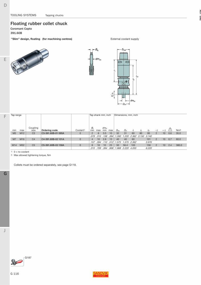
G 116
TOOLING SYSTEMS Tapping chucks
E
F
G
J
D
G
RO
T - E
NG
TOOLING SYSTEMS Tapping chucks
Floating rubber collet chuckCoromant Capto 391.60B
''Slim'' design, floating (for machining centres) External coolant supply
Tap range Tap shank mm, inch Dimensions, mm, inch
min maxCoupling
size Ordering code Coolant1)Bk
min maxdmm min max D5m D21 l1 l3 l21 - z + z U Nm2)
M5 M12 C3 C3-391.60B-01 095A 0 2 8 3.5 10 32 31 60 80 95 2 10 0.6 35.0.079 .315 .138 .394 1.260 1.220 2.362 3.150 3.740
M7 M16 C4 C4-391.60B-02 101A 0 4 10 2.8 13 40 40 60 101 2 10 0.7 60.0.157 .394 .110 .512 1.575 1.575 2.362 3.976
M14 M32 C5 C5-391.60B-03 158A 0 8 18 10 23 50 56.4 103 158 2 10 2.4 380.0.315 .709 .394 .906 1.968 2.220 4.055 6.220
1) 0 = no coolant2) Max allowed tightening torque, Nm
Collets must be ordered separately, see page G118.
G187
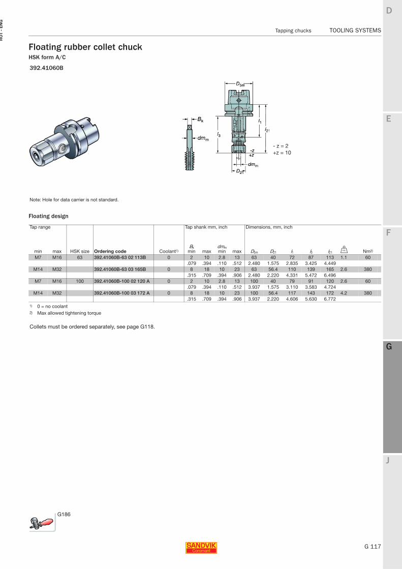
E
G 117
F
G
J
D
G
Tapping chucks TOOLING SYSTEMS
RO
T -
EN
G
TOOLING SYSTEMS Tapping chucks
Floating rubber collet chuckHSK form A/C
Floating design
392.41060B
- z = 2+z = 10
Note: Hole for data carrier is not standard.
Tap range Tap shank mm, inch Dimensions, mm, inch
min max HSK size Ordering code Coolant1)Bk
min maxdmm min max D5m D21 l1 l3 l21 U Nm2)
M7 M16 63 392.41060B-63 02 113B 0 2 10 2.8 13 63 40 72 87 113 1.1 60.079 .394 .110 .512 2.480 1.575 2.835 3.425 4.449
M14 M32 392.41060B-63 03 165B 0 8 18 10 23 63 56.4 110 139 165 2.6 380.315 .709 .394 .906 2.480 2.220 4.331 5.472 6.496
M7 M16 100 392.41060B-100 02 120 A 0 2 10 2.8 13 100 40 79 91 120 2.6 60.079 .394 .110 .512 3.937 1.575 3.110 3.583 4.724
M14 M32 392.41060B-100 03 172 A 0 8 18 10 23 100 56.4 117 143 172 4.2 380.315 .709 .394 .906 3.937 2.220 4.606 5.630 6.772
1) 0 = no coolant2) Max allowed tightening torque
Collets must be ordered separately, see page G118.
G186
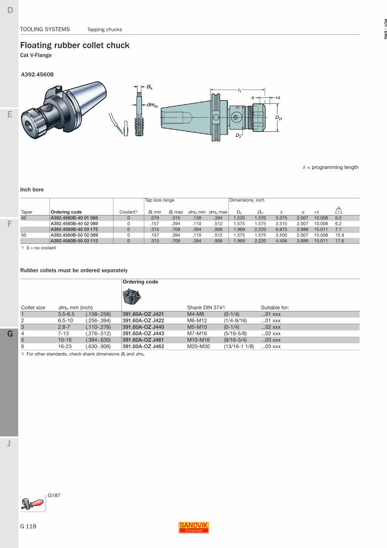
G 118
TOOLING SYSTEMS Tapping chucks
E
F
G
J
D
G
RO
T - E
NG
TOOLING SYSTEMS Tapping chucks
Floating rubber collet chuckCat V-Flange
Inch bore
Rubber collets must be ordered separately
A392.4560B
l1 = programming length
Tap size range Dimensions, inch
Taper Ordering code Coolant1) Bk min Bk max dmm min dmm max D2 D21 l1 -z +z V
40 A392.4560B-40 01 085 0 .079 .315 .138 .394 1.220 1.220 3.375 2.007 10.008 6.0A392.4560B-40 02 089 0 .157 .394 .110 .512 1.575 1.575 3.515 2.007 10.008 6.2A392.4560B-40 03 175 0 .315 .709 .394 .906 1.969 2.220 6.875 3.988 15.011 7.1
50 A392.4560B-50 02 089 0 .157 .394 .110 .512 1.575 1.575 3.500 2.007 10.008 15.9A392.4560B-50 03 112 0 .315 .709 .394 .906 1.969 2.220 4.406 3.988 15.011 17.6
1) 0 = no coolant
Ordering code
Collet size dmm mm (inch) Shank DIN 3741) Suitable for:1 3.5-6.5 (.138-.256) 391.60A-OZ J421 M4-M8 (0-1/4) ...01 xxx2 6.5-10 (.256-.394) 391.60A-OZ J422 M6-M12 (1/4-9/16) ...01 xxx3 2.8-7 (.110-.276) 391.60A-OZ J440 M5-M10 (0-1/4) ...02 xxx4 7-13 (.276-.512) 391.60A-OZ J443 M7-M16 (5/16-5/8) ...02 xxx5 10-16 (.394-.630) 391.60A-OZ J461 M10-M16 (9/16-3/4) ...03 xxx6 16-23 (.630-.906) 391.60A-OZ J462 M20-M30 (13/16-1 1/8) ...03 xxx1) For other standards, check shank dimensions Bk and dmm
G187
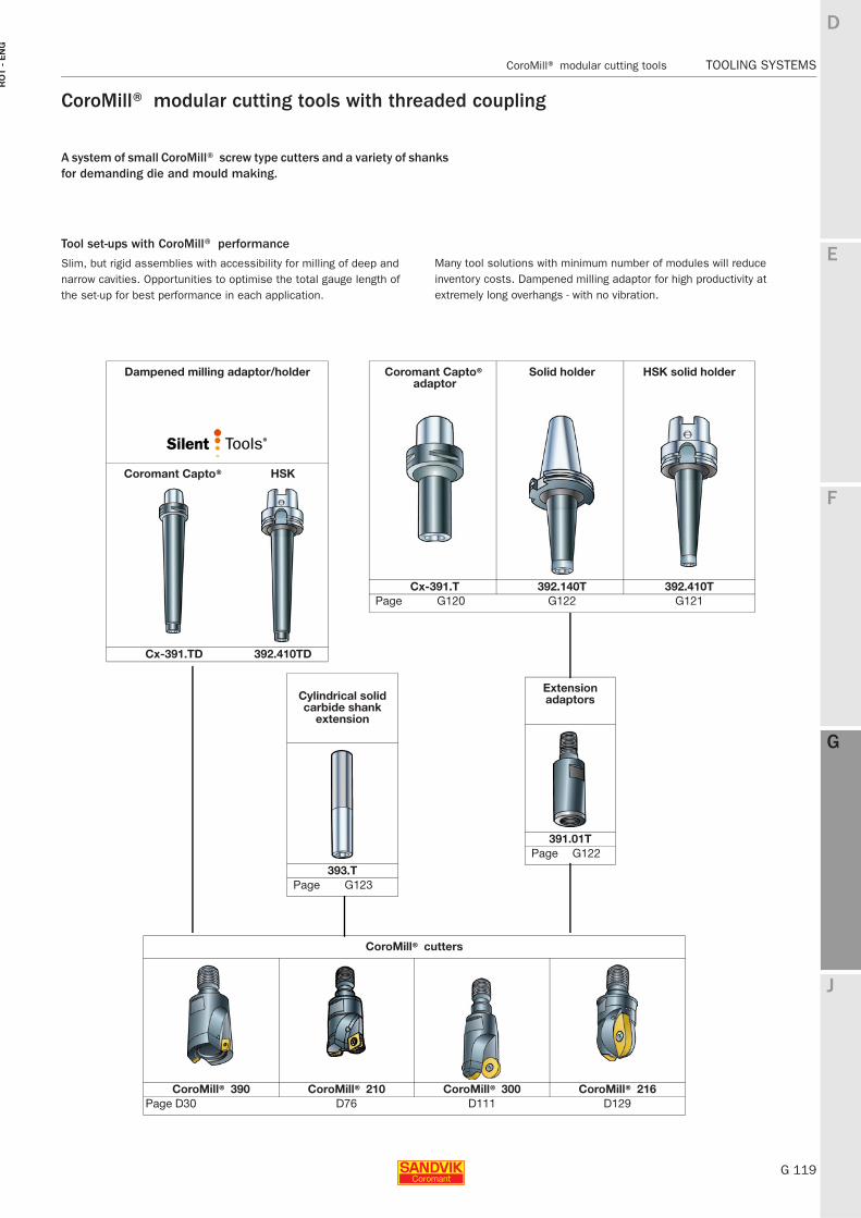
E
G 119
F
G
J
D
G
CoroMill® modular cutting tools TOOLING SYSTEMS
RO
T -
EN
G
TOOLING SYSTEMS CoroMill® modular cutting tools
CoroMill® modular cutting tools with threaded coupling
A system of small CoroMill® screw type cutters and a variety of shanks for demanding die and mould making.
Tool set-ups with CoroMill® performance
Slim, but rigid assemblies with accessibility for milling of deep and narrow cavities. Opportunities to optimise the total gauge length of the set-up for best performance in each application.
Many tool solutions with minimum number of modules will reduce inventory costs. Dampened milling adaptor for high productivity at extremely long overhangs - with no vibration.
Dampened milling adaptor/holder
Coromant Capto® HSK
Cx-391.TD 392.410TD
Coromant Capto® adaptor
Solid holder HSK solid holder
Cx-391.T 392.140T 392.410TPage G120 G122 G121
Cylindrical solid carbide shank
extension
393.TPage G123
Extension adaptors
391.01TPage G122
CoroMill® cutters
CoroMill® 390 CoroMill® 210 CoroMill® 300 CoroMill® 216Page D30 D76 D111 D129
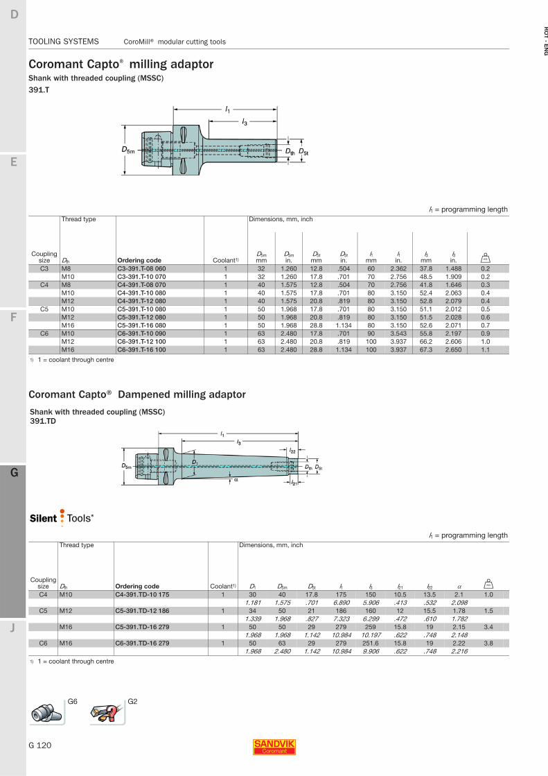
G 120
TOOLING SYSTEMS CoroMill® modular cutting tools
E
F
G
J
D
G
RO
T - E
NG
TOOLING SYSTEMS CoroMill® modular cutting tools
Coromant Capto® milling adaptorShank with threaded coupling (MSSC)391.T
Coromant Capto® Dampened milling adaptor
l1 = programming lengthThread type Dimensions, mm, inch
Coupling size Dth Ordering code Coolant1)
D5mmm
D5min.
D5tmm
D5tin.
l1mm
l1in.
l3mm
l3in. U
C3 M8 C3-391.T-08 060 1 32 1.260 12.8 .504 60 2.362 37.8 1.488 0.2M10 C3-391.T-10 070 1 32 1.260 17.8 .701 70 2.756 48.5 1.909 0.2
C4 M8 C4-391.T-08 070 1 40 1.575 12.8 .504 70 2.756 41.8 1.646 0.3M10 C4-391.T-10 080 1 40 1.575 17.8 .701 80 3.150 52.4 2.063 0.4M12 C4-391.T-12 080 1 40 1.575 20.8 .819 80 3.150 52.8 2.079 0.4
C5 M10 C5-391.T-10 080 1 50 1.968 17.8 .701 80 3.150 51.1 2.012 0.5M12 C5-391.T-12 080 1 50 1.968 20.8 .819 80 3.150 51.5 2.028 0.6M16 C5-391.T-16 080 1 50 1.968 28.8 1.134 80 3.150 52.6 2.071 0.7
C6 M10 C6-391.T-10 090 1 63 2.480 17.8 .701 90 3.543 55.8 2.197 0.9M12 C6-391.T-12 100 1 63 2.480 20.8 .819 100 3.937 66.2 2.606 1.0M16 C6-391.T-16 100 1 63 2.480 28.8 1.134 100 3.937 67.3 2.650 1.1
1) 1 = coolant through centre
Shank with threaded coupling (MSSC)391.TD
l1 = programming lengthThread type Dimensions, mm, inch
Coupling size Dth Ordering code Coolant1) D1 D5m D5t l1 l3 l21 l22 α U
C4 M10 C4-391.TD-10 175 1 30 40 17.8 175 150 10.5 13.5 2.1 1.01.181 1.575 .701 6.890 5.906 .413 .532 2.098
C5 M12 C5-391.TD-12 186 1 34 50 21 186 160 12 15.5 1.78 1.51.339 1.968 .827 7.323 6.299 .472 .610 1.782
M16 C5-391.TD-16 279 1 50 50 29 279 259 15.8 19 2.15 3.41.968 1.968 1.142 10.984 10.197 .622 .748 2.148
C6 M16 C6-391.TD-16 279 1 50 63 29 279 251.6 15.8 19 2.22 3.81.968 2.480 1.142 10.984 9.906 .622 .748 2.216
1) 1 = coolant through centre
G6 G2
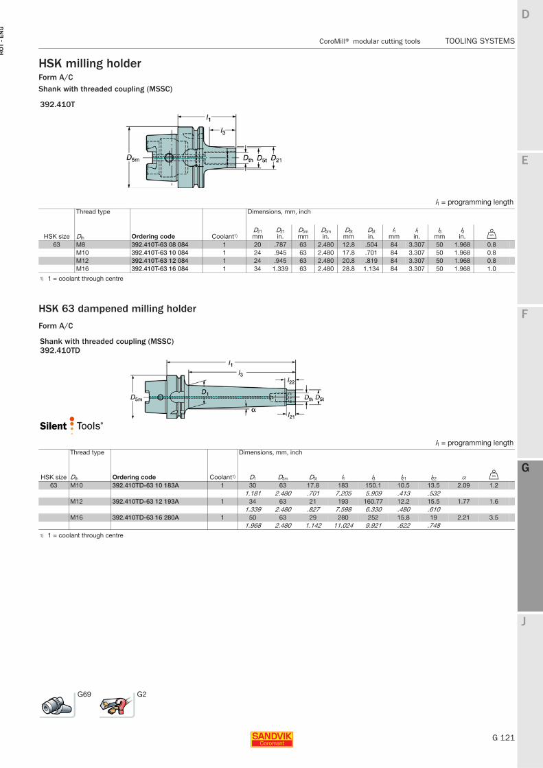
E
G 121
F
G
J
D
G
CoroMill® modular cutting tools TOOLING SYSTEMS
RO
T -
EN
G
TOOLING SYSTEMS CoroMill® modular cutting tools
HSK milling holderForm A/CShank with threaded coupling (MSSC)
HSK 63 dampened milling holder
Form A/C
392.410T
l1 = programming lengthThread type Dimensions, mm, inch
HSK size Dth Ordering code Coolant1)D21mm
D21in.
D5mmm
D5min.
D5tmm
D5tin.
l1mm
l1in.
l3mm
l3in. U
63 M8 392.410T-63 08 084 1 20 .787 63 2.480 12.8 .504 84 3.307 50 1.968 0.8M10 392.410T-63 10 084 1 24 .945 63 2.480 17.8 .701 84 3.307 50 1.968 0.8M12 392.410T-63 12 084 1 24 .945 63 2.480 20.8 .819 84 3.307 50 1.968 0.8M16 392.410T-63 16 084 1 34 1.339 63 2.480 28.8 1.134 84 3.307 50 1.968 1.0
1) 1 = coolant through centre
Shank with threaded coupling (MSSC)392.410TD
l1 = programming lengthThread type Dimensions, mm, inch
HSK size Dth Ordering code Coolant1) D1 D5m D5t l1 l3 l21 l22 α U
63 M10 392.410TD-63 10 183A 1 30 63 17.8 183 150.1 10.5 13.5 2.09 1.21.181 2.480 .701 7.205 5.909 .413 .532
M12 392.410TD-63 12 193A 1 34 63 21 193 160.77 12.2 15.5 1.77 1.61.339 2.480 .827 7.598 6.330 .480 .610
M16 392.410TD-63 16 280A 1 50 63 29 280 252 15.8 19 2.21 3.51.968 2.480 1.142 11.024 9.921 .622 .748
1) 1 = coolant through centre
G69 G2
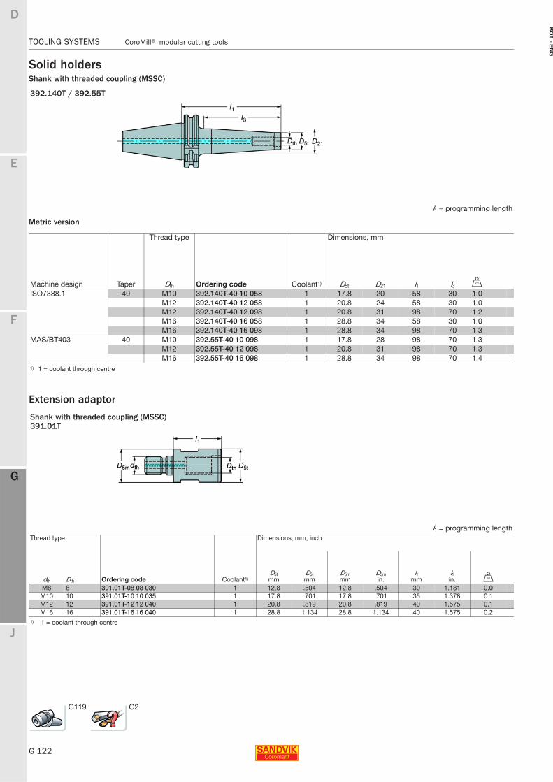
G 122
TOOLING SYSTEMS CoroMill® modular cutting tools
E
F
G
J
D
G
RO
T - E
NG
TOOLING SYSTEMS CoroMill® modular cutting tools
Solid holdersShank with threaded coupling (MSSC)
Metric version
Extension adaptor
392.140T / 392.55T
l1 = programming length
Thread type Dimensions, mm
Machine design Taper Dth Ordering code Coolant1) D5t D21 l1 l3 U
ISO7388.1 40 M10 392.140T-40 10 058 1 17.8 20 58 30 1.0M12 392.140T-40 12 058 1 20.8 24 58 30 1.0M12 392.140T-40 12 098 1 20.8 31 98 70 1.2M16 392.140T-40 16 058 1 28.8 34 58 30 1.0M16 392.140T-40 16 098 1 28.8 34 98 70 1.3
MAS/BT403 40 M10 392.55T-40 10 098 1 17.8 28 98 70 1.3M12 392.55T-40 12 098 1 20.8 31 98 70 1.3M16 392.55T-40 16 098 1 28.8 34 98 70 1.4
1) 1 = coolant through centre
Shank with threaded coupling (MSSC)391.01T
l1 = programming lengthThread type Dimensions, mm, inch
dth Dth Ordering code Coolant1)D5tmm
D5tmm
D5mmm
D5min.
l1mm
l1in. U
M8 8 391.01T-08 08 030 1 12.8 .504 12.8 .504 30 1.181 0.0M10 10 391.01T-10 10 035 1 17.8 .701 17.8 .701 35 1.378 0.1M12 12 391.01T-12 12 040 1 20.8 .819 20.8 .819 40 1.575 0.1M16 16 391.01T-16 16 040 1 28.8 1.134 28.8 1.134 40 1.575 0.2
1) 1 = coolant through centre
G119 G2
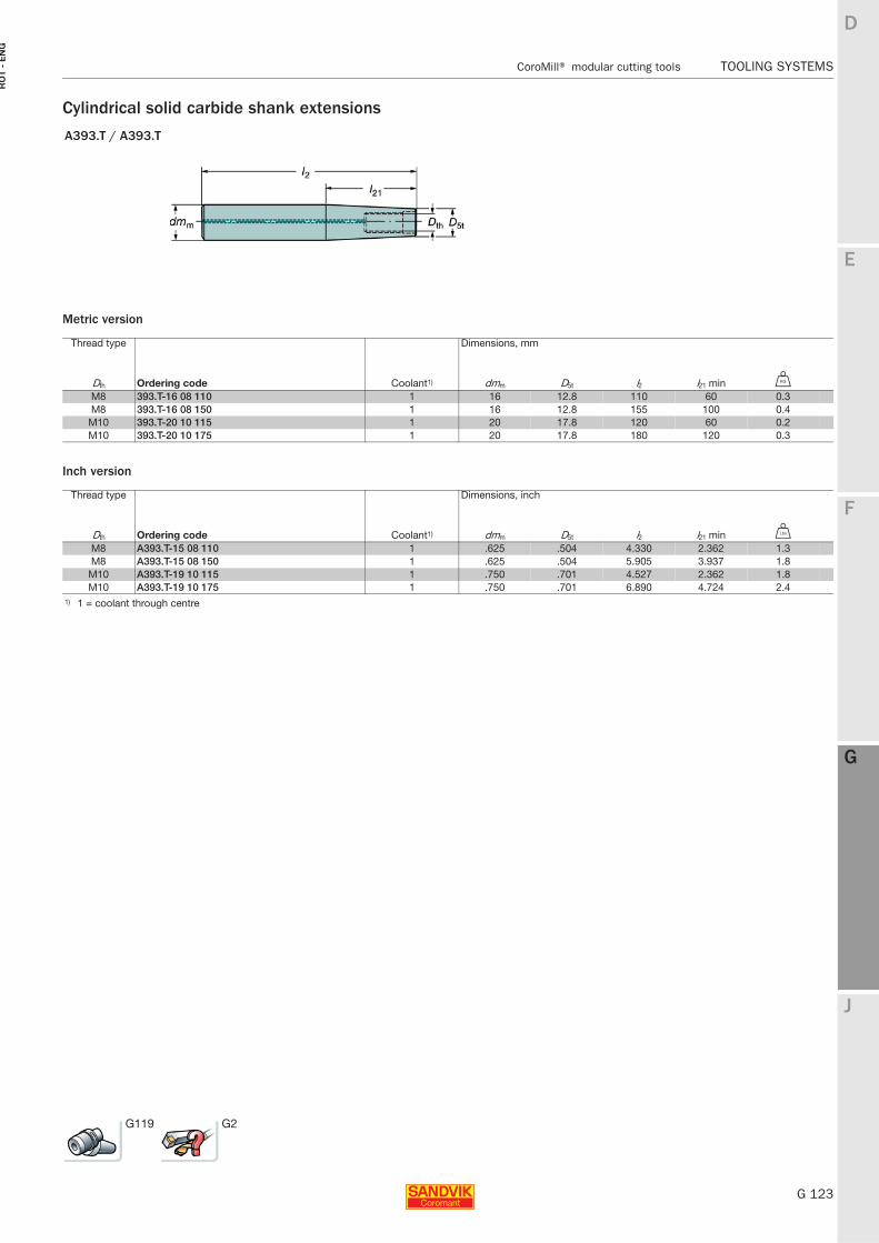
E
G 123
F
G
J
D
G
CoroMill® modular cutting tools TOOLING SYSTEMS
RO
T -
EN
G
TOOLING SYSTEMS CoroMill® modular cutting tools
Cylindrical solid carbide shank extensions
Metric version
Inch version
A393.T / A393.T
Thread type Dimensions, mm
Dth Ordering code Coolant1) dmm D5t l2 l21 min U
M8 393.T-16 08 110 1 16 12.8 110 60 0.3M8 393.T-16 08 150 1 16 12.8 155 100 0.4
M10 393.T-20 10 115 1 20 17.8 120 60 0.2M10 393.T-20 10 175 1 20 17.8 180 120 0.3
Thread type Dimensions, inch
Dth Ordering code Coolant1) dmm D5t l2 l21 min V
M8 A393.T-15 08 110 1 .625 .504 4.330 2.362 1.3M8 A393.T-15 08 150 1 .625 .504 5.905 3.937 1.8
M10 A393.T-19 10 115 1 .750 .701 4.527 2.362 1.8M10 A393.T-19 10 175 1 .750 .701 6.890 4.724 2.4
1) 1 = coolant through centre
G119 G2
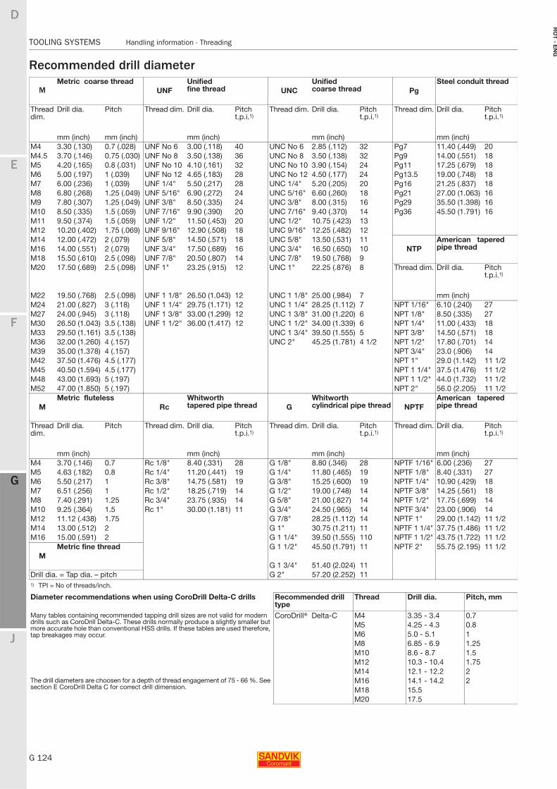
G 124
TOOLING SYSTEMS Handling information - Threading
E
F
G
J
D
G
RO
T - E
NG
TOOLING SYSTEMS Handling information - Threading
Recommended drill diameter
MMetric coarse thread
UNFUnified fine thread UNC
Unified coarse thread Pg
Steel conduit thread
Thread dim.
Drill dia. Pitch Thread dim. Drill dia. Pitch t.p.i.1)
Thread dim. Drill dia. Pitch t.p.i.1)
Thread dim. Drill dia. Pitch t.p.i.1)
mm (inch) mm (inch) mm (inch) mm (inch) mm (inch)M4 3.30 (.130) 0.7 (.028) UNF No 6 3.00 (.118) 40 UNC No 6 2.85 (.112) 32 Pg7 11.40 (.449) 20M4.5 3.70 (.146) 0.75 (.030) UNF No 8 3.50 (.138) 36 UNC No 8 3.50 (.138) 32 Pg9 14.00 (.551) 18M5 4.20 (.165) 0.8 (.031) UNF No 10 4.10 (.161) 32 UNC No 10 3.90 (.154) 24 Pg11 17.25 (.679) 18M6 5.00 (.197) 1 (.039) UNF No 12 4.65 (.183) 28 UNC No 12 4.50 (.177) 24 Pg13.5 19.00 (.748) 18M7 6.00 (.236) 1 (.039) UNF 1/4" 5.50 (.217) 28 UNC 1/4" 5.20 (.205) 20 Pg16 21.25 (.837) 18M8 6.80 (.268) 1.25 (.049) UNF 5/16" 6.90 (.272) 24 UNC 5/16" 6.60 (.260) 18 Pg21 27.00 (1.063) 16M9 7.80 (.307) 1.25 (.049) UNF 3/8" 8.50 (.335) 24 UNC 3/8" 8.00 (.315) 16 Pg29 35.50 (1.398) 16M10 8.50 (.335) 1.5 (.059) UNF 7/16" 9.90 (.390) 20 UNC 7/16" 9.40 (.370) 14 Pg36 45.50 (1.791) 16M11 9.50 (.374) 1.5 (.059) UNF 1/2" 11.50 (.453) 20 UNC 1/2" 10.75 (.423) 13M12 10.20 (.402) 1.75 (.069) UNF 9/16" 12.90 (.508) 18 UNC 9/16" 12.25 (.482) 12M14 12.00 (.472) 2 (.079) UNF 5/8" 14.50 (.571) 18 UNC 5/8" 13.50 (.531) 11
NTPAmerican tapered pipe threadM16 14.00 (.551) 2 (.079) UNF 3/4" 17.50 (.689) 16 UNC 3/4" 16.50 (.650) 10
M18 15.50 (.610) 2.5 (.098) UNF 7/8" 20.50 (.807) 14 UNC 7/8" 19.50 (.768) 9M20 17.50 (.689) 2.5 (.098) UNF 1" 23.25 (.915) 12 UNC 1" 22.25 (.876) 8 Thread dim. Drill dia. Pitch
t.p.i.1)
M22 19.50 (.768) 2.5 (.098) UNF 1 1/8" 26.50 (1.043) 12 UNC 1 1/8" 25.00 (.984) 7 mm (inch)M24 21.00 (.827) 3 (.118) UNF 1 1/4" 29.75 (1.171) 12 UNC 1 1/4" 28.25 (1.112) 7 NPT 1/16" 6.10 (.240) 27M27 24.00 (.945) 3 (.118) UNF 1 3/8" 33.00 (1.299) 12 UNC 1 3/8" 31.00 (1.220) 6 NPT 1/8" 8.50 (.335) 27M30 26.50 (1.043) 3.5 (.138) UNF 1 1/2" 36.00 (1.417) 12 UNC 1 1/2" 34.00 (1.339) 6 NPT 1/4" 11.00 (.433) 18M33 29.50 (1.161) 3.5 (.138) UNC 1 3/4" 39.50 (1.555) 5 NPT 3/8" 14.50 (.571) 18M36 32.00 (1.260) 4 (.157) UNC 2" 45.25 (1.781) 4 1/2 NPT 1/2" 17.80 (.701) 14M39 35.00 (1.378) 4 (.157) NPT 3/4" 23.0 (.906) 14M42 37.50 (1.476) 4.5 (.177) NPT 1" 29.0 (1.142) 11 1/2M45 40.50 (1.594) 4.5 (.177) NPT 1 1/4" 37.5 (1.476) 11 1/2M48 43.00 (1.693) 5 (.197) NPT 1 1/2" 44.0 (1.732) 11 1/2M52 47.00 (1.850) 5 (.197) NPT 2" 56.0 (2.205) 11 1/2
MMetric fluteless
RcWhitworth tapered pipe thread G
Whitworth cylindrical pipe thread NPTF
American tapered pipe thread
Thread dim.
Drill dia. Pitch Thread dim. Drill dia. Pitch t.p.i.1)
Thread dim. Drill dia. Pitch t.p.i.1)
Thread dim. Drill dia. Pitch t.p.i.1)
mm (inch) mm (inch) mm (inch) mm (inch)M4 3.70 (.146) 0.7 Rc 1/8" 8.40 (.331) 28 G 1/8" 8.80 (.346) 28 NPTF 1/16" 6.00 (.236) 27M5 4.63 (.182) 0.8 Rc 1/4" 11.20 (.441) 19 G 1/4" 11.80 (.465) 19 NPTF 1/8" 8.40 (.331) 27M6 5.50 (.217) 1 Rc 3/8" 14.75 (.581) 19 G 3/8" 15.25 (.600) 19 NPTF 1/4" 10.90 (.429) 18M7 6.51 (.256) 1 Rc 1/2" 18.25 (.719) 14 G 1/2" 19.00 (.748) 14 NPTF 3/8" 14.25 (.561) 18M8 7.40 (.291) 1.25 Rc 3/4" 23.75 (.935) 14 G 5/8" 21.00 (.827) 14 NPTF 1/2" 17.75 (.699) 14M10 9.25 (.364) 1.5 Rc 1" 30.00 (1.181) 11 G 3/4" 24.50 (.965) 14 NPTF 3/4" 23.00 (.906) 14M12 11.12 (.438) 1.75 G 7/8" 28.25 (1.112) 14 NPTF 1" 29.00 (1.142) 11 1/2M14 13.00 (.512) 2 G 1" 30.75 (1.211) 11 NPTF 1 1/4" 37.75 (1.486) 11 1/2M16 15.00 (.591) 2 G 1 1/4" 39.50 (1.555) 110 NPTF 1 1/2" 43.75 (1.722) 11 1/2
MMetric fine thread G 1 1/2" 45.50 (1.791) 11 NPTF 2" 55.75 (2.195) 11 1/2
G 1 3/4" 51.40 (2.024) 11Drill dia. = Tap dia. – pitch G 2" 57.20 (2.252) 111) TPI = No of threads/inch.
Diameter recommendations when using CoroDrill Delta-C drills Recommended drill type
Thread Drill dia. Pitch, mm
Many tables containing recommended tapping drill sizes are not valid for modern drills such as CoroDrill Delta-C. These drills normally produce a slightly smaller but more accurate hole than conventional HSS drills. If these tables are used therefore, tap breakages may occur.
CoroDrill® Delta-C M4 3.35 - 3.4 0.7M5 4.25 - 4.3 0.8M6 5.0 - 5.1 1M8 6.85 - 6.9 1.25M10 8.6 - 8.7 1.5M12 10.3 - 10.4 1.75M14 12.1 - 12.2 2
The drill diameters are choosen for a depth of thread engagement of 75 - 66 %. See section E CoroDrill Delta C for correct drill dimension.
M16 14.1 - 14.2 2M18 15.5M20 17.5
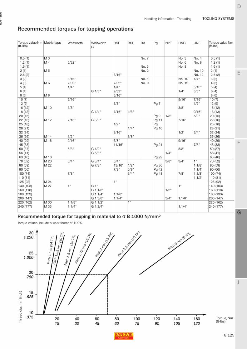
E
G 125
F
G
J
D
G
Handling information - Threading TOOLING SYSTEMS
RO
T -
EN
G
TOOLING SYSTEMS Handling information - Threading
Recommended torques for tapping operations
Example: Thread M20 x 2.5 Recommended torque = 70 Nm
Recommended torque for tapping in material to σ B 1000 N/mm2
Torque values include a wear factor of 100%.
Torque value Nm (ft-lbs)
Metric taps Whitworth Whitworth BSF BSP BA Pg NPT UNC UNF Torque value Nm (ft-lbs)G
0.5 (1) M 3 No. 7 No. 3 No. 4 0.5 (1)1.2 (1) M 4 5/32" No. 6 No. 8 1.2 (1)1.6 (1) No. 3 No. 8 1.6 (1)2 (1) M 5 No. 2 No. 10 2 (1)2.5 (2) 3/16" No. 12 2.5 (2)3 (2) 3/16" No. 1 No. 10 1/4" 3 (2)4 (3) M 6 7/32" 7/32" No. 0 No. 12 4 (3)5 (4) 1/4" 1/4" 5/16" 5 (4)6 (4) G 1/8" 9/32" 1/4" 3/8" 6 (4)8 (6) M 8 5/16" 8 (6)10 (7) 5/16" 5/16" 7/16" 10 (7)12 (9) 3/8" Pg 7 1/2" 12 (9)16 (12) M 10 3/8" 3/8" 16 (12)18 (13) G 1/4" 7/16" 1/8" 9/16" 18 (13)20 (15) Pg 9 1/8" 5/8" 20 (15)22 (16) M 12 7/16" G 3/8" Pg 11 7/16" 22 (16)25 (18) 1/2" Pg 25 (18)28 (21) 1/4" Pg 16 28 (21)32 (24) 9/16" 1/2" 3/4" 32 (24)36 (26) M 14 1/2" 3/8" 36 (26)40 (29) M 16 9/16" 5/8" 9/16" 40 (29)45 (33) 11/16" Pg 21 7/8" 45 (33)50 (37) 5/8" G 1/2" 5/8" 50 (37)56 (41) G 5/8" 1/4" 56 (41)63 (46) M 18 Pg 29 63 (46)70 (52) M 20 3/4" G 3/4" 3/4" 3/8" 3/4" 1" 70 (52)80 (59) M 22 G 7/8" 13/16" 1/2" Pg 36 1.1/8" 80 (59)90 (66) 7/8" 5/8" Pg 42 1.1/4" 90 (66)
100 (74) 7/8" 3/4" Pg 48 7/8" 1.3/8" 100 (74)110 (81) 1.1/2" 110 (81)125 (92) M 24 1" 125 (92)140 (103) M 27 1" G 1" 1" 140 (103)160 (118) G 1.1/8" 1/2" 160 (118)180 (133) G 1.1/4" 1.1/8" 180 (133)200 (147) G 1.3/8" 1.1/4" 3/4" 1.1/8" 200 (147)220 (162) M 30 1.1/8" G 1.1/2" 1" 220 (162)240 (177) M 33 1.1/4" G 1.3/4" 1.1/4" 240 (177)
Thre
ad d
ia, m
m (i
nch)
Torque, Nm (ft-lbs).
Pitc
h 1 m
m (24 T
PI)
Pitc
h 1.
25 m
m (2
0 TP
I)Pi
tch
1.5
mm
(18
TPI)
Pitc
h 1.
75 m
m (1
6 TP
I)
Pitc
h 2
mm
(13
TPI)
Pitc
h 2.
5 m
m (1
0 TP
I)
Pitch
3 mm (8
TPI)
G 126
TOOLING SYSTEMS Index for accessories and spare parts
E
F
G
J
D
G
RO
T - E
NG
TOOLING SYSTEMS Index for accessories and spare parts
Accessories Page
Fixtures G127Drawbolts G128Coolant tubes for Coromant Capto® G129Safe control G129Assembly tools for extension / reduction adaptors G130
Torque wrench for tool changing G130Tightening torque recommendations G131
Cassettes with tapered polygon seating G132
Locking mechanism for casettes G133Pull studs G134Cylindrical collets, sealed G135Cylindrical collets, slitted G136Extractor for cylindrical collets G137
Spare parts Page
Rotating tool holders
Coromant Capto® basic holders G145
Coromant Capto® adaptorsExtension/reduction adaptors G148Coromant Capto adaptor for Varilock G148Adaptors for side and face mills G149Adaptors for face mills and square shoulder face mills G150
Shrink fit adaptor G156Adaptors for Weldon shanks G156Adaptors for drills with Whistle Notch shanks G157
Adaptor for Weldon/ ISO 9766 G158Adaptors for drills with Coromant Whistle Notch shank G159
Adaptors for drills with ISO 9766 shank G159Drill chuck G159Collet chuck adaptors G159
Coromant solid holding toolsHolders for face mills and square shoulder face mills G160
Collet chuck holders G164Holders for Weldon shanks G165ER Collet chuck, BIG PLUS G166Weldon/ ISO 9766 G166Holders for drills G168
Page
ER collets, DIN 6499-B G138ER collets, metallic sealed G139
ER Collet sealing discs G140ER collet nuts for through-coolant G141
ER tapping collets G142Master setting gauges G143
Alignment tool G143Lockscrews for arbors G144
Page
HSK solid holders
Basic holders G170Face mill holder G171Collet chuck holder G174Weldon shank holder G174Whistle Notch holder G175Holder for drills G176Tapping chucks G181Coolant tube G176
Hydro-Grip high precision chuck
Coromant Capto® adaptor for face mills G177
Coromant Capto® chuck adaptor G177Coromant solid holder for face mills G178
Coromant solid collet chuck G178
Solid holder for facemills G179Heavy Duty G179HSK solid holder for face mills G180
HSK solid collet chuck G180
Tapping chucks
SynchroFlex® ER tapping chuck G181Quick change tapping chuck G185Floating rubber collet chuck G186
For spare parts for Coromant Capto® multi-task machining tools, see chapter H
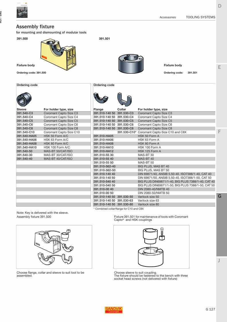
E
G 127
F
G
J
D
G
Accessories TOOLING SYSTEMS
RO
T -
EN
G
TOOLING SYSTEMS Accessories
Assembly fixturefor mounting and dismounting of modular tools
391.500 391.501
Fixture body Fixture body
Ordering code: 391.500 Ordering code: 391.501
Ordering code Ordering code
Sleeve For holder type, size Flange Collar For holder type, size391.540-C3 Coromant Capto Size C3 391.510-140 50 391.530-C3 Coromant Capto Size C3391.540-C4 Coromant Capto Size C4 391.510-140 50 391.530-C4 Coromant Capto Size C4391.540-C5 Coromant Capto Size C5 391.510-140 50 391.530-C5 Coromant Capto Size C5391.540-C6 Coromant Capto Size C6 391.510-140 50 391.530-C6 Coromant Capto Size C6391.540-C8 Coromant Capto Size C8 391.510-140 50 391.530-C8 Coromant Capto Size C8391.540-C10 Coromant Capto Size C10 391.530-C10* Coromant Capto Size C10 and C8X391.540-HA05 HSK 50 Form A/C 391.510-HA05 HSK 50 Form A391.540-HA06 HSK 63 Form A/C 391.510-HA06 HSK 63 Form A391.540-HA08 HSK 80 Form A/C 391.510-HA08 HSK 80 Form A391.540-HA10 HSK 100 Form A/C 391.510-HA10 HSK 100 Form A391.540-50 MAS-BT 50/CAT/ISO 391.510-HA12 HSK 125 Form A391.540-30 MAS-BT 30/CAT/ISO 391.510-55 30 MAS-BT 30391.540-40 MAS-BT 40/CAT/ISO 391.510-55 40 MAS-BT 40
391.510-55 50 MAS-BT 50391.510-562-40 BIG PLUS, MAS BT 40391.510-562-50 BIG PLUS, MAS BT 50391.510-140 40 DIN 69871/40, ANSIB 5.50-40. ISO7388/1-40, CAT 40391.510-140 50 DIN 69871/50, ANSIB 5.50-40. ISO7388/1-50, CAT 50391.510-540 40 BIG PLUS DIN69871/1-40, BIG PLUS 7388/1-40, CAT 40391.510-540 50 BIG PLUS DIN69871/1-50, BIG PLUS 7388/1-50, CAT 50391.510-00 40 DIN 2080-40/NMTB 40391.510-00 50 DIN 2080-50/NMTB 50391.510-140 50 391.530-50 Varilock size 50391.510-140 50 391.530-63 Varilock size 63391.510-140 50 391.530-80 Varilock size 80* Combined collar/flange for C10 and C8X
Note: Key is delivered with the sleeve.Assembly fixture 391.500 Fixture 391.501 for maintenance of tools with Coromant
Capto® and HSK couplings
Choose flange, collar and sleeve to suit tool to be assembled.
Choose sleeve to suit coupling.The fixture should be fastened to the bench with three socket head screws (not delivered with fixture)
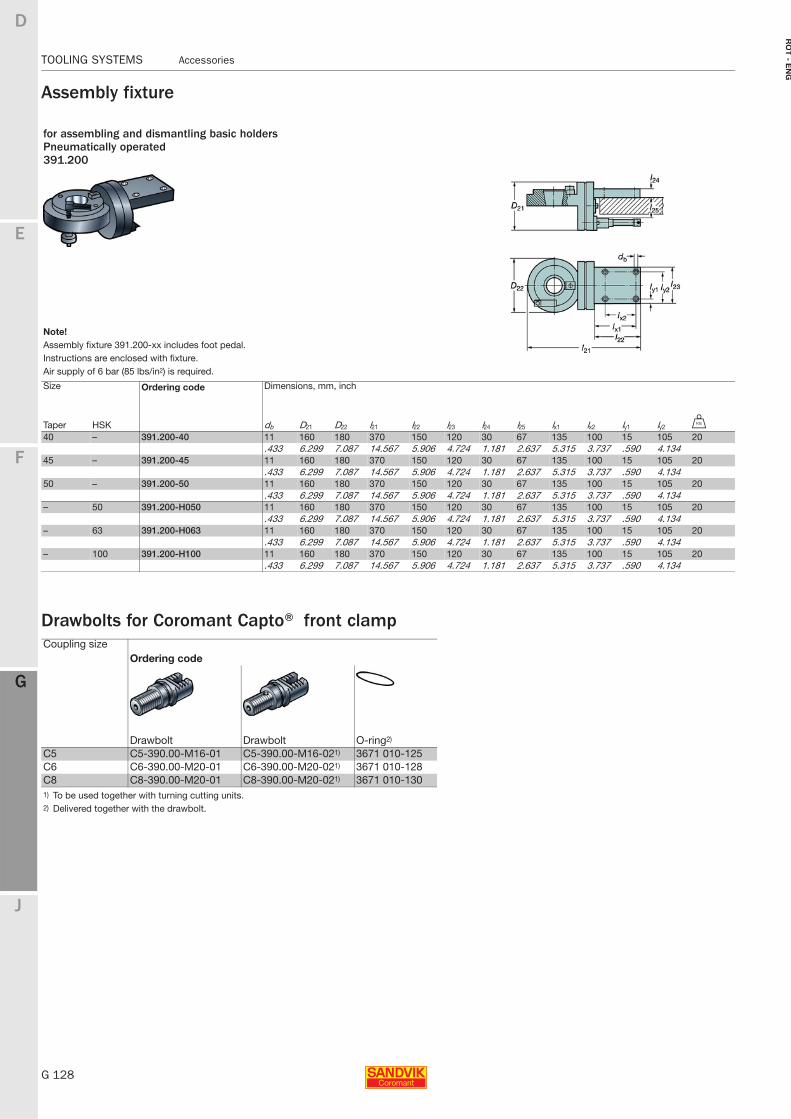
G 128
TOOLING SYSTEMS Accessories
E
F
G
J
D
G
RO
T - E
NG
TOOLING SYSTEMS Accessories
Assembly fixture
Drawbolts for Coromant Capto® front clamp
for assembling and dismantling basic holdersPneumatically operated391.200
Note!Assembly fixture 391.200-xx includes foot pedal.Instructions are enclosed with fixture.Air supply of 6 bar (85 lbs/in2) is required.
Size Ordering code Dimensions, mm, inch
Taper HSK db D21 D22 l21 l22 l23 l24 l25 lx1 lx2 ly1 ly2 U
40 – 391.200-40 11 160 180 370 150 120 30 67 135 100 15 105 20.433 6.299 7.087 14.567 5.906 4.724 1.181 2.637 5.315 3.737 .590 4.134
45 – 391.200-45 11 160 180 370 150 120 30 67 135 100 15 105 20.433 6.299 7.087 14.567 5.906 4.724 1.181 2.637 5.315 3.737 .590 4.134
50 – 391.200-50 11 160 180 370 150 120 30 67 135 100 15 105 20.433 6.299 7.087 14.567 5.906 4.724 1.181 2.637 5.315 3.737 .590 4.134
– 50 391.200-H050 11 160 180 370 150 120 30 67 135 100 15 105 20.433 6.299 7.087 14.567 5.906 4.724 1.181 2.637 5.315 3.737 .590 4.134
– 63 391.200-H063 11 160 180 370 150 120 30 67 135 100 15 105 20.433 6.299 7.087 14.567 5.906 4.724 1.181 2.637 5.315 3.737 .590 4.134
– 100 391.200-H100 11 160 180 370 150 120 30 67 135 100 15 105 20.433 6.299 7.087 14.567 5.906 4.724 1.181 2.637 5.315 3.737 .590 4.134
Coupling sizeOrdering code
Drawbolt Drawbolt O-ring2)
C5 C5-390.00-M16-01 C5-390.00-M16-021) 3671 010-125C6 C6-390.00-M20-01 C6-390.00-M20-021) 3671 010-128C8 C8-390.00-M20-01 C8-390.00-M20-021) 3671 010-1301) To be used together with turning cutting units.2) Delivered together with the drawbolt.
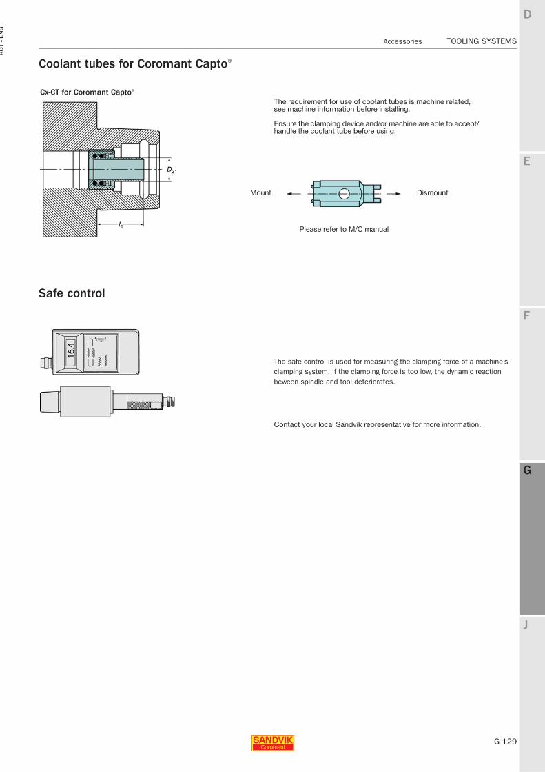
E
G 129
F
G
J
D
G
Accessories TOOLING SYSTEMS
RO
T -
EN
G
TOOLING SYSTEMS Accessories
Coolant tubes for Coromant Capto®
Safe control
Cx-CT for Coromant Capto®
The requirement for use of coolant tubes is machine related, see machine information before installing.
Ensure the clamping device and/or machine are able to accept/handle the coolant tube before using.
Mount Dismount
Please refer to M/C manual
The safe control is used for measuring the clamping force of a machine’s clamping system. If the clamping force is too low, the dynamic reaction beween spindle and tool deteriorates.
Contact your local Sandvik representative for more information.
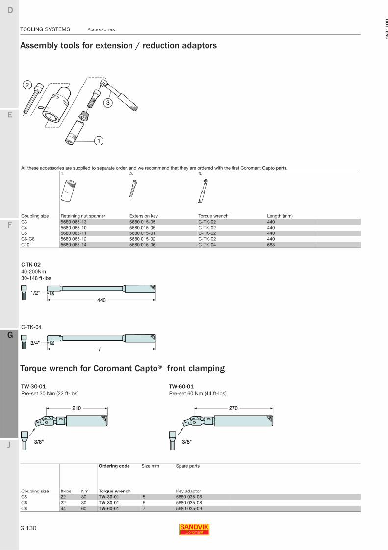
G 130
TOOLING SYSTEMS Accessories
E
F
G
J
D
G
RO
T - E
NG
TOOLING SYSTEMS Accessories
Assembly tools for extension / reduction adaptors
Torque wrench for Coromant Capto® front clamping
All these accessories are supplied to separate order, and we recommend that they are ordered with the first Coromant Capto parts.1. 2. 3.
Coupling size Retaining nut spanner Extension key Torque wrench Length (mm)C3 5680 065-13 5680 015-05 C-TK-02 440C4 5680 065-10 5680 015-05 C-TK-02 440C5 5680 065-11 5680 015-01 C-TK-02 440C6-C8 5680 065-12 5680 015-02 C-TK-02 440C10 5680 065-14 5680 015-06 C-TK-04 683
C-TK-0240-200Nm30-148 ft-lbs
C-TK-04
TW-30-01 TW-60-01Pre-set 30 Nm (22 ft-lbs) Pre-set 60 Nm (44 ft-lbs)
Ordering code Size mm Spare parts
Coupling size Torque wrench Key adaptorft-lbs NmC5 22 30 TW-30-01 5 5680 035-08C6 22 30 TW-30-01 5 5680 035-08C8 44 60 TW-60-01 7 5680 035-09
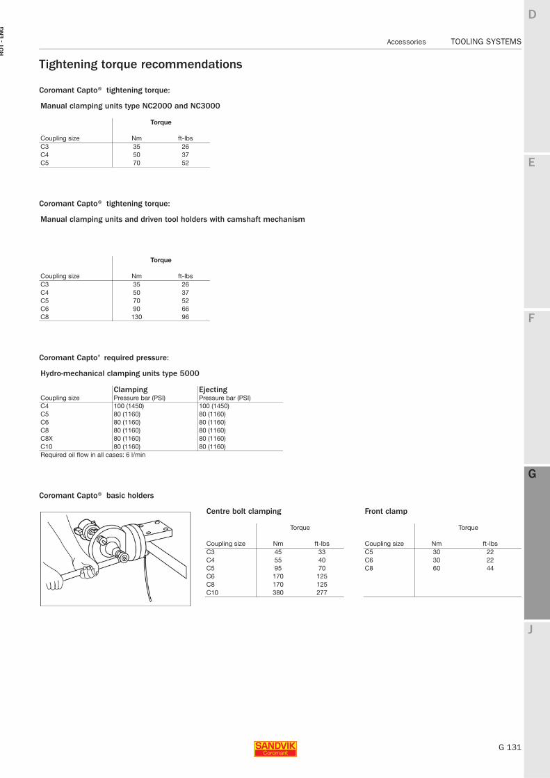
E
G 131
F
G
J
D
G
Accessories TOOLING SYSTEMS
RO
T -
EN
G
TOOLING SYSTEMS Accessories
Tightening torque recommendations
Coromant Capto® tightening torque:
Coromant Capto® tightening torque:
Coromant Capto® required pressure:
Coromant Capto® basic holders
Manual clamping units type NC2000 and NC3000
Torque
Coupling size Nm ft-lbsC3 35 26C4 50 37C5 70 52
Manual clamping units and driven tool holders with camshaft mechanism
Torque
Coupling size Nm ft-lbsC3 35 26C4 50 37C5 70 52C6 90 66C8 130 96
Hydro-mechanical clamping units type 5000
Clamping EjectingCoupling size Pressure bar (PSI) Pressure bar (PSI)C4 100 (1450) 100 (1450)C5 80 (1160) 80 (1160)C6 80 (1160) 80 (1160) C8 80 (1160) 80 (1160)C8X 80 (1160) 80 (1160)C10 80 (1160) 80 (1160)Required oil flow in all cases: 6 l/min
Centre bolt clamping Front clamp
Torque Torque
Coupling size Nm ft-lbs Coupling size Nm ft-lbsC3 45 33 C5 30 22C4 55 40 C6 30 22C5 95 70 C8 60 44C6 170 125C8 170 125C10 380 277
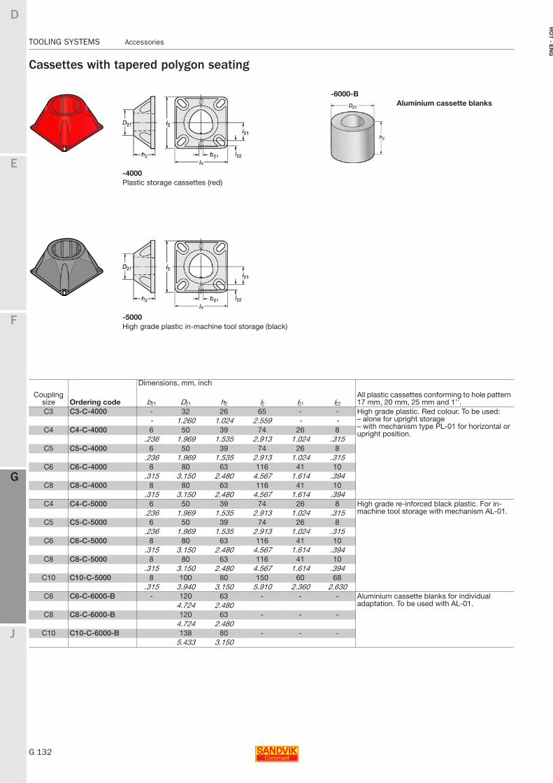
G 132
TOOLING SYSTEMS Accessories
E
F
G
J
D
G
RO
T - E
NG
TOOLING SYSTEMS Accessories
Cassettes with tapered polygon seating
-6000-BAluminium cassette blanks
-4000Plastic storage cassettes (red)
-5000High grade plastic in-machine tool storage (black)
Coupling size Ordering code
Dimensions, mm, inch
All plastic cassettes conforming to hole pattern 17 mm, 20 mm, 25 mm and 1''.b21 D21 h2 l2 l21 l22
C3 C3-C-4000 - 32 26 65 - - High grade plastic. Red colour. To be used:– alone for upright storage – with mechanism type PL-01 for horizontal or upright position.
- 1.260 1.024 2.559 - -C4 C4-C-4000 6 50 39 74 26 8
.236 1.969 1.535 2.913 1.024 .315C5 C5-C-4000 6 50 39 74 26 8
.236 1.969 1.535 2.913 1.024 .315C6 C6-C-4000 8 80 63 116 41 10
.315 3.150 2.480 4.567 1.614 .394C8 C8-C-4000 8 80 63 116 41 10
.315 3.150 2.480 4.567 1.614 .394C4 C4-C-5000 6 50 39 74 26 8 High grade re-inforced black plastic. For in-
machine tool storage with mechanism AL-01..236 1.969 1.535 2.913 1.024 .315C5 C5-C-5000 6 50 39 74 26 8
.236 1.969 1.535 2.913 1.024 .315C6 C6-C-5000 8 80 63 116 41 10
.315 3.150 2.480 4.567 1.614 .394C8 C8-C-5000 8 80 63 116 41 10
.315 3.150 2.480 4.567 1.614 .394C10 C10-C-5000 8 100 80 150 60 68
.315 3.940 3.150 5.910 2.360 2.630C6 C6-C-6000-B - 120 63 - - - Aluminium cassette blanks for individual
adaptation. To be used with AL-01.4.724 2.480C8 C8-C-6000-B 120 63 - - -
4.724 2.480C10 C10-C-6000-B 138 80 - - -
5.433 3.150
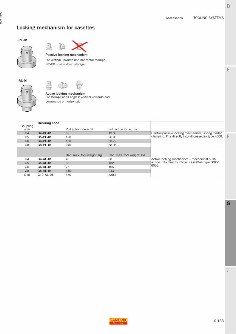
E
G 133
F
G
J
D
G
Accessories TOOLING SYSTEMS
RO
T -
EN
G
TOOLING SYSTEMS Accessories
Locking mechanism for casettes
-PL-01
Passive locking mechanism
For vertical upwards and horizontal storage. NEVER upside down storage.
-AL-01
Active locking mechanismFor storage at all angles: vertical upwards and downwords or horizontal.
Couplingsize
Ordering code
Pull action force, N Pull action force, lbsC4 C4-PL-01 55 12.36 Central passive locking mechanism. Spring loaded
clamping. Fits directly into all cassettes type 4000.C5 C5-PL-01 120 26.98C6 C6-PL-01 150 33.72C8 C8-PL-01 240 53.95
Rec. max. tool weight, kg Rec. max. tool weight, lbsC4 C4-AL-01 40 88 Active locking mechanism – mechanical push
action. Fits directly into all cassettes type 5000/6000.
C5 C5-AL-01 60 132C6 C6-AL-01 75 165C8 C8-AL-01 110 243
C10 C10-AL-01 150 330.7
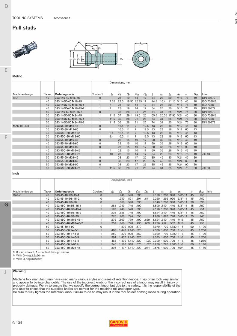
G 134
TOOLING SYSTEMS Accessories
E
F
G
J
D
G
RO
T - E
NG
TOOLING SYSTEMS Accessories
Pull studs
Metric
Inch
Dimensions, mm
Machine design Taper Ordering code Coolant1) dch D1 D21 D22 D23 l2 l21 l23 dth α BKW InfoISO 40 393.140-40 M16-75 0 23 19 14 17 54 26 20 M16 75 19 DIN 69872
40 393.140C-40 M16-45 1 7.35 22.5 18.95 12.95 17 44.5 16.4 11.15 M16 45 18 ISO 7388 B40 393.140C-40 M16-75-1 1 7 23 19 14 17 54 26 20 M16 75 19 ISO 738840 393.140C-40 M16-75-2 1 7 23 19 14 17 54 26 20 M16 75 19 DIN 6987250 393.140-50 M24-75 2) 0 36 28 21 25 74 34 25 M24 75 30 DIN 69872 50 393.140C-50 M24-45 1 11.5 37 29.1 19.6 25 65.5 25.55 17.95 M24 45 30 ISO 7388 B50 393.140C-50 M24-75-1 1 11.5 36 28 21 25 74 34 25 M24 75 30 ISO 738850 393.140C-50 M24-75-2 1 11.5 36 28 21 25 74 34 25 M24 75 30 DIN 69872
MAS-BT 403 30 393.55-30 M12-45 0 16.5 11 7 12.5 43 23 18 M12 45 1330 393.55-30 M12-60 0 16.5 11 7 12.5 43 23 18 M12 60 1330 393.55C-30 M12-45 1 2.4 16.5 11 7 12.5 43 23 18 M12 45 1330 393.55C-30 M12-60 1 2.4 16.5 11 7 12.5 43 23 18 M12 60 1340 393.55-40 M16-45 0 23 15 10 17 60 35 28 M16 45 1940 393.55-40 M16-60 0 23 15 10 17 60 35 28 M16 60 1940 393.55-40 M16-90 0 23 15 10 17 60 35 28 M16 90 1940 393.55C-40 M16-45 1 4 23 15 10 17 60 35 28 M16 45 1940 393.55C-40 M16-75 1 10 23 19 14 17 54 29 23 M16 75 19 JIS 4050 393.55-50 M24-45 0 38 23 17 25 85 45 35 M24 45 3050 393.55-50 M24-60 0 38 23 17 25 85 45 35 M24 60 3050 393.55-50 M24-90 0 38 23 17 25 85 45 35 M24 90 3050 393.55C-50 M24-75 1 11.5 36 28 21 25 74 34 25 M24 75 30 JIS 50
Dimensions, inch
Machine design Taper Ordering code Coolant1) dch D1 D21 D22 D23 l2 l21 l23 dth α BKW InfoCAT-V 40 393.45-40 5/8-45-1 0 .940 .590 .390 2.120 1.260 .990 5/8"-11 45 .750
40 393.45-40 5/8-45-2 0 .940 .591 .394 .641 2.250 1.266 .990 5/8"-11 45 .75040 393.45-40 5/8-90 0 .860 .590 .390 2.140 1.280 .990 5/8"-11 90 .69040 393.45C-40 5/8-45-1 1 .281 .940 .740 .490 1.500 .640 .440 5/8"-11 45 .75040 393.45C-40 5/8-45-2 1 .197 .940 .590 .390 2.120 1.260 .990 5/8"-11 45 .75140 393.45C-40 5/8-45-3 1 .236 .858 .740 .490 1.624 .640 .440 5/8"-11 45 .75040 393.45C-40 5/8-75 1 .276 .900 .744 .550 1.880 1.020 .790 5/8"-11 75 .74040 393.45C-40 M16-45-1 1 .276 .860 .739 .490 .669 1.624 .640 .440 M16 45 .75040 393.45C-40 M16-45-2 1 .252 .866 .740 .490 .669 1.736 .752 .552 M16 45 .75050 393.45-50 1-90 0 1.370 .900 .670 3.070 1.770 1.380 1"-8 90 1.19050 393.45C-50 1-45-1 1 .468 1.440 1.140 .820 2.300 1.000 .700 1"-8 45 1.25050 393.45C-50 1-45-2 1 .250 1.370 .900 .660 3.090 1.790 1.380 1"-8 45 1.19050 393.45C-50 1-45-3 1 .394 1.437 1.140 .820 2.575 1.000 .700 1"-8 45 1.25050 393.45C-50 1-45-4 1 .468 1.430 1.140 .820 1.030 2.300 1.000 .700 1"-8 45 1.25050 393.45C-50 1-60 3) 1 .240 1.500 .910 .670 1.020 3.250 1.770 1.380 1"-8 60 1.18050 393.45C-50 M24-45 1 .394 1.437 1.140 .820 .984 2.575 1.000 .700 M24 45 1.180
1) 0 = no coolant, 1 = coolant through centre2) With O-ring 2.5x20mm3) With O-ring 3x20mm
Warning!
Machine tool manufacturers have used many various styles and sizes of retention knobs. They often look very similar and appear to be interchangeble. The use of the incorrect knob, or the incorrect use of a knob, may result in injury or property damage. We try to ensure that we specify the correct knob, but due to the variety, it is the responsibility of the end user to check that the supplied knobs are correct for the machine toll and taper type.Be sure to fully tighten the retention knob. Failure to do so may result in the tool holder coming loose during operation.
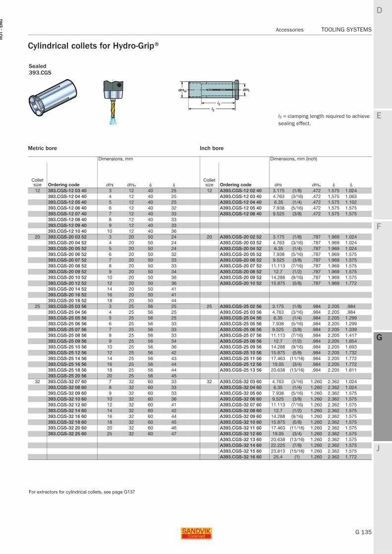
E
G 135
F
G
J
D
G
Accessories TOOLING SYSTEMS
RO
T -
EN
G
TOOLING SYSTEMS Accessories
Cylindrical collets for Hydro-Grip®
l3 = clamping length required to achieve sealing effect.
Sealed393.CGS
Metric bore
Dimensions, mm
Collet size Ordering code dmt dmm l2 l312 393.CGS-12 03 40 3 12 40 25
393.CGS-12 04 40 4 12 40 25393.CGS-12 05 40 5 12 40 25393.CGS-12 06 40 6 12 40 32393.CGS-12 07 40 7 12 40 33393.CGS-12 08 40 8 12 40 33393.CGS-12 09 40 9 12 40 33393.CGS-12 10 40 10 12 40 36
20 393.CGS-20 03 52 3 20 50 24393.CGS-20 04 52 4 20 50 24393.CGS-20 05 52 5 20 50 24393.CGS-20 06 52 6 20 50 32393.CGS-20 07 52 7 20 50 33393.CGS-20 08 52 8 20 50 33393.CGS-20 09 52 9 20 50 34393.CGS-20 10 52 10 20 50 36393.CGS-20 12 52 12 20 50 36393.CGS-20 14 52 14 20 50 41393.CGS-20 16 52 16 20 50 41393.CGS-20 18 52 18 20 50 44
25 393.CGS-25 03 56 3 25 56 25393.CGS-25 04 56 4 25 56 25393.CGS-25 05 56 5 25 56 25393.CGS-25 06 56 6 25 56 33393.CGS-25 07 56 7 25 56 33393.CGS-25 08 56 8 25 56 33393.CGS-25 09 56 9 25 56 34393.CGS-25 10 56 10 25 56 36393.CGS-25 12 56 12 25 56 42393.CGS-25 14 56 14 25 56 43393.CGS-25 16 56 16 25 56 44393.CGS-25 18 56 18 25 56 44393.CGS-25 20 56 20 25 56 45
32 393.CGS-32 07 60 7 32 60 33393.CGS-32 08 60 8 32 60 33393.CGS-32 09 60 9 32 60 33393.CGS-32 10 60 10 32 60 36393.CGS-32 12 60 12 32 60 41393.CGS-32 14 60 14 32 60 42393.CGS-32 16 60 16 32 60 44393.CGS-32 18 60 18 32 60 45393.CGS-32 20 60 20 32 60 46393.CGS-32 25 60 25 32 60 47
Inch bore
Dimensions, mm (inch)
Collet size Ordering code dmt dmm l2 l312 A393.CGS-12 02 40 3.175 (1/8) .472 1.575 1.024
A393.CGS-12 03 40 4.763 (3/16) .472 1.575 1.063A393.CGS-12 04 40 6.35 (1/4) .472 1.575 1.102A393.CGS-12 05 40 7.938 (5/16) .472 1.575 1.575A393.CGS-12 06 40 9.525 (3/8) .472 1.575 1.575
20 A393.CGS-20 02 52 3.175 (1/8) .787 1.969 1.024A393.CGS-20 03 52 4.763 (3/16) .787 1.969 1.024A393.CGS-20 04 52 6.35 (1/4) .787 1.969 1.024A393.CGS-20 05 52 7.938 (5/16) .787 1.969 1.575A393.CGS-20 06 52 9.525 (3/8) .787 1.969 1.575A393.CGS-20 07 52 11.113 (7/16) .787 1.969 1.575A393.CGS-20 08 52 12.7 (1/2) .787 1.969 1.575A393.CGS-20 09 52 14.288 (9/16) .787 1.969 1.575A393.CGS-20 10 52 15.875 (5/8) .787 1.969 1.772
25 A393.CGS-25 02 56 3.175 (1/8) .984 2.205 .984A393.CGS-25 03 56 4.763 (3/16) .984 2.205 .984A393.CGS-25 04 56 6.35 (1/4) .984 2.205 1.299A393.CGS-25 05 56 7.938 (5/16) .984 2.205 1.299A393.CGS-25 06 56 9.525 (3/8) .984 2.205 1.339A393.CGS-25 07 56 11.113 (7/16) .984 2.205 1.417A393.CGS-25 08 56 12.7 (1/2) .984 2.205 1.654A393.CGS-25 09 56 14.288 (9/16) .984 2.205 1.693A393.CGS-25 10 56 15.875 (5/8) .984 2.205 1.732A393.CGS-25 11 56 17.463 (11/16) .984 2.205 1.772A393.CGS-25 12 56 19.05 (3/4) .984 2.205 1.772A393.CGS-25 13 56 20.638 (13/16) .984 2.205 1.811
32 A393.CGS-32 03 60 4.763 (3/16) 1.260 2.362 1.024A393.CGS-32 04 60 6.35 (1/4) 1.260 2.362 1.024A393.CGS-32 05 60 7.938 (5/16) 1.260 2.362 1.575A393.CGS-32 06 60 9.525 (3/8) 1.260 2.362 1.575A393.CGS-32 07 60 11.113 (7/16) 1.260 2.362 1.575A393.CGS-32 08 60 12.7 (1/2) 1.260 2.362 1.575A393.CGS-32 09 60 14.288 (9/16) 1.260 2.362 1.575A393.CGS-32 10 60 15.875 (5/8) 1.260 2.362 1.575A393.CGS-32 11 60 17.463 (11/16) 1.260 2.362 1.575A393.CGS-32 12 60 19.05 (3/4) 1.260 2.362 1.575A393.CGS-32 13 60 20.638 (13/16) 1.260 2.362 1.575A393.CGS-32 14 60 22.225 (7/8) 1.260 2.362 1.575A393.CGS-32 15 60 23.813 (15/16) 1.260 2.362 1.575A393.CGS-32 16 60 25.4 (1) 1.260 2.362 1.772
For extractors for cylindrical collets, see page G137
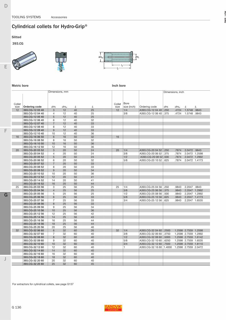
G 136
TOOLING SYSTEMS Accessories
E
F
G
J
D
G
RO
T - E
NG
TOOLING SYSTEMS Accessories
Cylindrical collets for Hydro-Grip®
For extractors for cylindrical collets, see page G137
Slitted
393.CG
Metric bore
Dimensions, mm
Collet size Ordering code dmt dmm l2 l312 393.CG-12 03 40 3 12 40 25
393.CG-12 04 40 4 12 40 25393.CG-12 05 40 5 12 40 25393.CG-12 06 40 6 12 40 32393.CG-12 07 40 7 12 40 33393.CG-12 08 40 8 12 40 33393.CG-12 09 40 9 12 40 33393.CG-12 10 40 10 12 40 36
16 393.CG-16 06 50 6 16 50 32393.CG-16 08 50 8 16 50 32393.CG-16 10 50 10 16 50 36393.CG-16 12 50 12 16 50 36
20 393.CG-20 03 52 3 20 50 24393.CG-20 04 52 4 20 50 24393.CG-20 05 52 5 20 50 24393.CG-20 06 52 6 20 50 32393.CG-20 07 52 7 20 50 33393.CG-20 08 52 8 20 50 33393.CG-20 09 52 9 20 50 34393.CG-20 10 52 10 20 50 36393.CG-20 12 52 12 20 50 41393.CG-20 14 52 14 20 50 41393.CG-20 16 52 16 20 50 44
25 393.CG-25 03 56 3 25 56 25393.CG-25 04 56 4 25 56 25393.CG-25 05 56 5 25 56 25393.CG-25 06 56 6 25 56 33393.CG-25 07 56 7 25 56 33393.CG-25 08 56 8 25 56 33393.CG-25 09 56 9 25 56 34393.CG-25 10 56 10 25 56 36393.CG-25 12 56 12 25 56 42393.CG-25 14 56 14 25 56 43 393.CG-25 16 56 16 25 56 44393.CG-25 18 56 18 25 56 44393.CG-25 20 56 20 25 56 46
32 393.CG-32 06 60 6 32 60 26393.CG-32 07 60 7 32 60 40393.CG-32 08 60 8 32 60 40393.CG-32 09 60 9 32 60 40393.CG-32 10 60 10 32 60 40393.CG-32 12 60 12 32 60 40393.CG-32 14 60 14 32 60 40393.CG-32 16 60 16 32 60 40393.CG-32 18 60 18 32 60 40393.CG-32 20 60 20 32 60 40393.CG-32 25 60 25 32 60 45
Inch bore
Dimensions, inch
Collet size
BoreOrdering codesize (inch) dmt dmm l2 l3
12 1/4 A393.CG-12 04 40 .250 .4724 1.5748 .98433/8 A393.CG-12 06 40 .375 .4724 1.5748 .9843
16
20 1/4 A393.CG-20 04 52 .250 .7874 2.0472 .98433/8 A393.CG-20 06 52 .375 .7874 2.0472 1.25981/2 A393.CG-20 08 52 .500 .7874 2.0472 1.29925/8 A393.CG-20 10 52 .625 .7874 2.0472 1.4173
25 1/4 A393.CG-25 04 56 .250 .9843 2.2047 .98433/8 A393.CG-25 06 56 .375 .9843 2.2047 1.29921/2 A393.CG-25 08 56 .500 .9843 2.2047 1.29925/8 A393.CG-25 10 56 .625 .9843 2.2047 1.41733/4 A393.CG-25 12 56 .625 .9843 2.2047 1.6535
32 1/4 A393.CG-32 04 60 .2500 1.2598 2.7559 1.25983/8 A393.CG-32 06 60 .3750 1.2598 2.7559 1.29921/2 A393.CG-32 08 60 .5000 1.2598 2.7559 1.61425/8 A393.CG-32 10 60 .6250 1.2598 2.7559 1.65353/4 A393.CG-32 12 60 .7500 1.2598 2.7559 1.81101 A393.CG-32 16 60 1.4000 1.2598 2.7559 2.0472
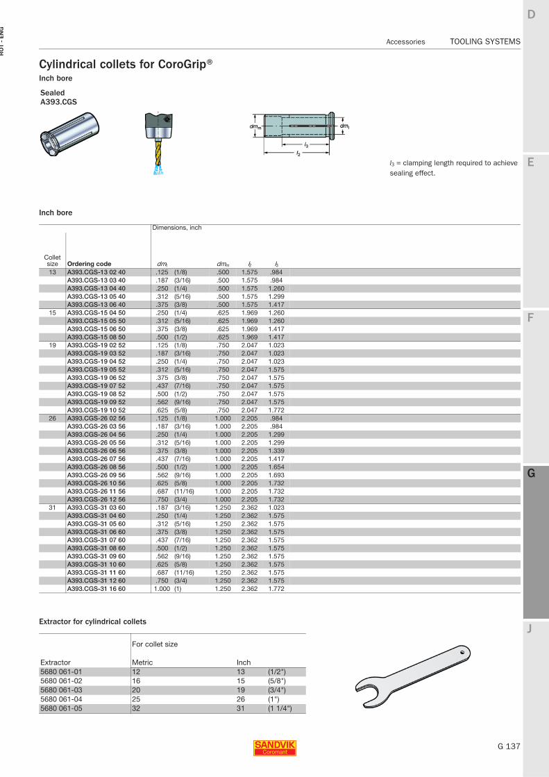
E
G 137
F
G
J
D
G
Accessories TOOLING SYSTEMS
RO
T -
EN
G
TOOLING SYSTEMS Accessories
Cylindrical collets for CoroGrip®Inch bore
l3 = clamping length required to achieve sealing effect.
Inch bore
Extractor for cylindrical collets
SealedA393.CGS
Dimensions, inch
Collet size Ordering code dmt dmm l2 l313 A393.CGS-13 02 40 .125 (1/8) .500 1.575 .984
A393.CGS-13 03 40 .187 (3/16) .500 1.575 .984A393.CGS-13 04 40 .250 (1/4) .500 1.575 1.260A393.CGS-13 05 40 .312 (5/16) .500 1.575 1.299A393.CGS-13 06 40 .375 (3/8) .500 1.575 1.417
15 A393.CGS-15 04 50 .250 (1/4) .625 1.969 1.260A393.CGS-15 05 50 .312 (5/16) .625 1.969 1.260A393.CGS-15 06 50 .375 (3/8) .625 1.969 1.417A393.CGS-15 08 50 .500 (1/2) .625 1.969 1.417
19 A393.CGS-19 02 52 .125 (1/8) .750 2.047 1.023A393.CGS-19 03 52 .187 (3/16) .750 2.047 1.023A393.CGS-19 04 52 .250 (1/4) .750 2.047 1.023A393.CGS-19 05 52 .312 (5/16) .750 2.047 1.575A393.CGS-19 06 52 .375 (3/8) .750 2.047 1.575A393.CGS-19 07 52 .437 (7/16) .750 2.047 1.575A393.CGS-19 08 52 .500 (1/2) .750 2.047 1.575A393.CGS-19 09 52 .562 (9/16) .750 2.047 1.575A393.CGS-19 10 52 .625 (5/8) .750 2.047 1.772
26 A393.CGS-26 02 56 .125 (1/8) 1.000 2.205 .984A393.CGS-26 03 56 .187 (3/16) 1.000 2.205 .984A393.CGS-26 04 56 .250 (1/4) 1.000 2.205 1.299A393.CGS-26 05 56 .312 (5/16) 1.000 2.205 1.299A393.CGS-26 06 56 .375 (3/8) 1.000 2.205 1.339A393.CGS-26 07 56 .437 (7/16) 1.000 2.205 1.417A393.CGS-26 08 56 .500 (1/2) 1.000 2.205 1.654A393.CGS-26 09 56 .562 (9/16) 1.000 2.205 1.693A393.CGS-26 10 56 .625 (5/8) 1.000 2.205 1.732A393.CGS-26 11 56 .687 (11/16) 1.000 2.205 1.732A393.CGS-26 12 56 .750 (3/4) 1.000 2.205 1.732
31 A393.CGS-31 03 60 .187 (3/16) 1.250 2.362 1.023A393.CGS-31 04 60 .250 (1/4) 1.250 2.362 1.575A393.CGS-31 05 60 .312 (5/16) 1.250 2.362 1.575A393.CGS-31 06 60 .375 (3/8) 1.250 2.362 1.575A393.CGS-31 07 60 .437 (7/16) 1.250 2.362 1.575A393.CGS-31 08 60 .500 (1/2) 1.250 2.362 1.575A393.CGS-31 09 60 .562 (9/16) 1.250 2.362 1.575A393.CGS-31 10 60 .625 (5/8) 1.250 2.362 1.575A393.CGS-31 11 60 .687 (11/16) 1.250 2.362 1.575A393.CGS-31 12 60 .750 (3/4) 1.250 2.362 1.575A393.CGS-31 16 60 1.000 (1) 1.250 2.362 1.772
Extractor
For collet size
Metric Inch 5680 061-01 12 13 (1/2")5680 061-02 16 15 (5/8")5680 061-03 20 19 (3/4")5680 061-04 25 26 (1")5680 061-05 32 31 (1 1/4")
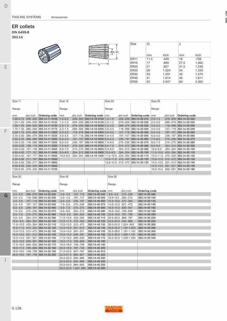
G 138
TOOLING SYSTEMS Accessories
E
F
G
J
D
G
RO
T - E
NG
TOOLING SYSTEMS Accessories
ER colletsDIN 6499-B393.14
Size D1 l2
mm Inch mm Inch ER11 11.4 .449 18 .709ER16 17 .669 27.5 1.062ER20 21 .827 31.5 1.240ER25 26 1.024 34 1.330ER32 33 1.291 40 1.575ER40 41 1.614 46 1.811ER50 52 2.047 60 2.362
Size 11 Size 16 Size 20 Size 25
Range
Ordering code
Range
Ordering code
Range
Ordering code
Range
Ordering codemm dmt inch mm dmt inch mm dmt inch mm dmt inch1.00–0.75 .039-.030 393.14-11 0100 1.0–0.5 .039-.020 393.14-16 0100 1.5–1.0 .059-.039 393.14-20 015 2.0–1.5 .079-.059 393.14-25 0201.25–1.00 .049-.039 393.14-11 0125 1.5–1.0 .059-.039 393.14-16 0150 2.0–1.5 .079-.059 393.14-20 020 2.5–2.0 .098-.079 393.14-25 0251.50–1.25 .059-.049 393.14-11 0150 2.0–1.0 .079-.039 393.14-16 0200 2.5–2.0 .098-.079 393.14-20 025 3.0–2.5 .118-.098 393.14-25 0301.75–1.50 .069-.059 393.14-11 0175 2.5–1.5 .098-.059 393.14-16 0250 3.0–2.5 .118-.098 393.14-20 030 4.0–3.0 .157-.118 393.14-25 0402.00–1.75 .079-.069 393.14-11 0200 3.0–2.0 .118-.079 393.14-16 0300 4.0–3.0 .157-.118 393.14-20 040 5.0–4.0 .197-.157 393.14-25 0502.25–2.00 .089-.079 393.14-11 0225 4.0–3.0 .157-.118 393.14-16 0400 5.0–4.0 .197-.157 393.14-20 050 6.0–5.0 .236-.197 393.14-25 0602.50–2.25 .098-.089 393.14-11 0250 5.0–4.0 .197-.157 393.14-16 0500 6.0–5.0 .236-.197 393.14-20 060 7.0–6.0 .275-.236 393.14-25 0703.00–2.50 .118-.098 393.14-11 0300 6.0–5.0 .236-.197 393.14-16 0600 7.0–6.0 .275-.236 393.14-20 070 8.0–7.0 .315-.275 393.14-25 0803.50–3.00 .138-.118 393.14-11 0350 7.0–6.0 .276-.236 393.14-16 0700 8.0–7.0 .315-.275 393.14-20 080 9.0–8.0 .354-.315 393.14-25 0904.00–3.50 .157-.138 393.14-11 0400 8.0–7.0 .315-.276 393.14-16 0800 9.0–8.0 .354-.315 393.14-20 090 10.0–9.0 .394-.354 393.14-25 1004.50–4.00 .177-.157 393.14-11 0450 9.0–8.0 .354-.315 393.14-16 0900 10.0–9.0 .394-.354 393.14-20 100 11.0–10.0 .433-.394 393.14-25 1105.00–4.50 .197-.177 393.14-11 0500 10.0–9.0 .394-.354 393.14-16 1000 11.0–10.0 .433-.394 393.14-20 110 12.0–11.0 .472-.433 393.14-25 1205.50–5.00 .217-.197 393.14-11 0550 12.0–11.0 .472-.433 393.14-20 120 13.0–12.0 .512-.472 393.14-25 1306.00–5.50 .236-.217 393.14-11 0600 13.0–12.0 .512-.472 393.14-20 130 14.0–13.0 .551-.512 393.14-25 1406.50–6.00 .256-.236 393.14-11 0650 15.0–14.0 .591-.551 393.14-25 1507.00-6.50 .276-.256 393.14-11 0700 16.0-15.0 .630-.591 393.14-25 160
Size 32 Size 40 Size 50
Range
Ordering code
Range
Ordering code
Range
Ordering codemm dmt inch mm dmt inch mm dmt inch2.5– 2.0 .098-.079 393.14-32 025 4.0– 3.0 .157-.118 393.14-40 040 8.0– 6.0 .315-.236 393.14-50 0803.0– 2.5 .118-.098 393.14-32 030 5.0– 4.0 .197-.157 393.14-40 050 10.0– 8.0 .394-.315 393.14-50 1004.0– 3.0 .157-.118 393.14-32 040 6.0– 5.0 .236-.197 393.14-40 060 12.0–10.0 .472-.394 393.14-50 1205.0– 4.0 .197-.157 393.14-32 050 7.0– 6.0 .275-.236 393.14-40 070 14.0–12.0 .551-.472 393.14-50 1406.0– 5.0 .236-.197 393.14-32 060 8.0– 7.0 .315-.275 393.14-40 080 16.0–14.0 .630-.551 393.14-50 1607.0– 6.0 .275-.236 393.14-32 070 9.0– 8.0 .354-.315 393.14-40 090 18.0–16.0 .709-.630 393.14-50 1808.0– 7.0 .315-.275 393.14-32 080 10.0– 9.0 .394-.354 393.14-40 100 20.0–18.0 .787-.709 393.14-50 2009.0– 8.0 .354-.315 393.14-32 090 11.0–10.0 .433-.394 393.14-40 110 22.0–20.0 .866-.787 393.14-50 22010.0– 9.0 .394-.354 393.14-32 100 12.0–11.0 .472-.433 393.14-40 120 24.0–22.0 .945-.866 393.14-50 24011.0–10.0 .433-.394 393.14-32 110 13.0–12.0 .512-.472 393.14-40 130 26.0–24.0 1.024-.945 393.14-50 26012.0–11.0 .472-.433 393.14-32 120 14.0–13.0 .551-.512 393.14-40 140 28.0–26.0 1.102-1.024 393.14-50 28013.0–12.0 .512-.472 393.14-32 130 15.0–14.0 .591-.551 393.14-40 150 30.0–28.0 1.181-1.102 393.14-50 30014.0–13.0 .551-.512 393.14-32 140 16.0–15.0 .630-.591 393.14-40 160 32.0–30.0 1.260-1.181 393.14-50 32015.0–14.0 .591-.551 393.14-32 150 17.0–16.0 .669-.630 393.14-40 170 34.0–32.0 1.339-1.260 393.14-50 34016.0–15.0 .630-.591 393.14-32 160 18.0–17.0 .709-.669 393.14-40 18017.0–16.0 .699-.630 393.14-32 170 19.0–18.0 .748-.709 393.14-40 19018.0–17.0 .709-.669 393.14-32 180 20.0–19.0 .787-.748 393.14-40 20019.0–18.0 .748-.709 393.14-32 190 21.0–20.0 .827-.787 393.14-40 21020.0–19.0 .787-.748 393.14-32 200 22.0–21.0 .866-.827 393.14-40 220
23.0–22.0 .906-.866 393.14-40 23024.0–23.0 .945-.906 393.14-40 24025.0–24.0 .984-.945 393.14-40 25026.0–25.0 1.024-.984 393.14-40 260
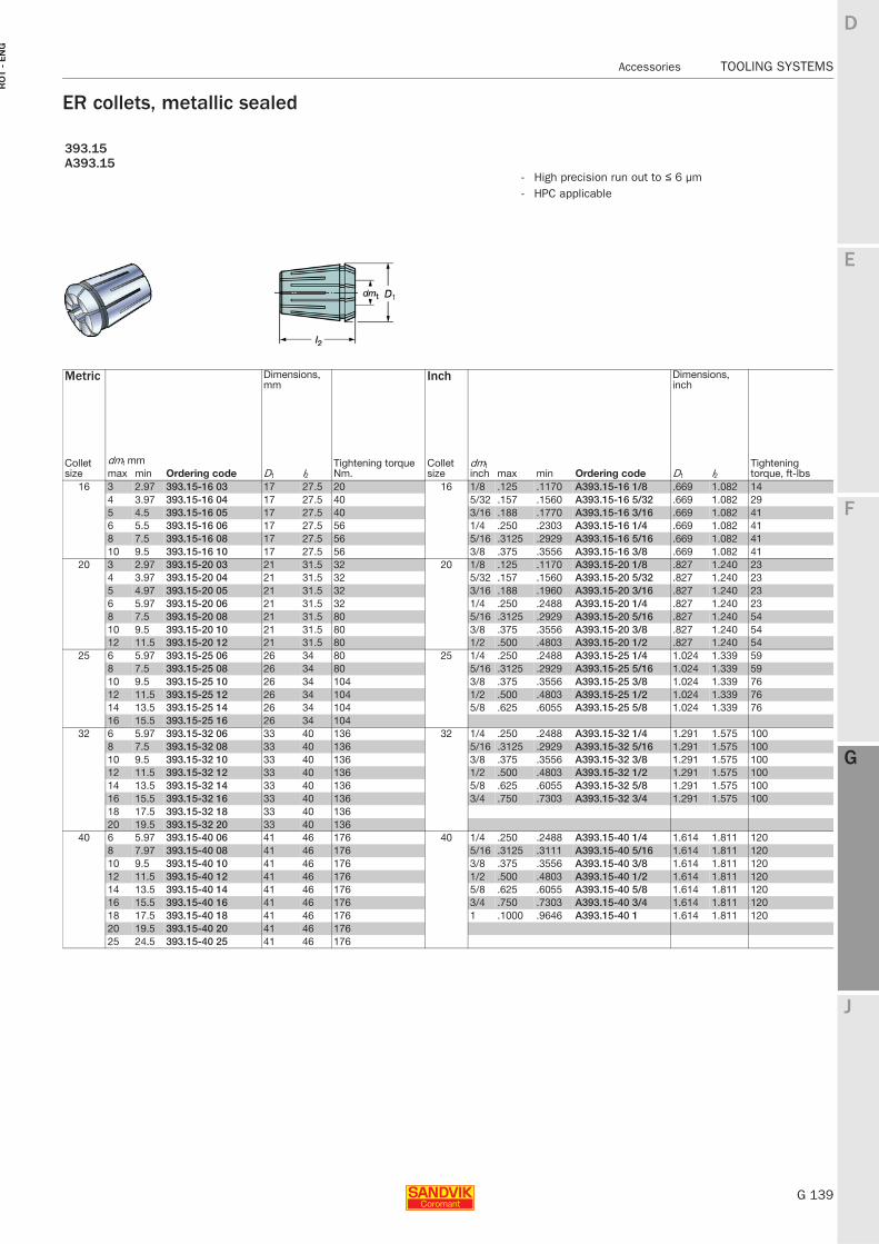
E
G 139
F
G
J
D
G
Accessories TOOLING SYSTEMS
RO
T -
EN
G
TOOLING SYSTEMS Accessories
ER collets, metallic sealed
393.15A393.15
- High precision run out to ≤ 6 µm- HPC applicable
Metric Dimensions, mm
Inch Dimensions, inch
Collet size
dmt mmOrdering code D1 l2
Tightening torque Nm.
Collet size
dmt inch Ordering code D1 l2
Tightening torque, ft-lbsmax min max min
16 3 2.97 393.15-16 03 17 27.5 20 16 1/8 .125 .1170 A393.15-16 1/8 .669 1.082 144 3.97 393.15-16 04 17 27.5 40 5/32 .157 .1560 A393.15-16 5/32 .669 1.082 295 4.5 393.15-16 05 17 27.5 40 3/16 .188 .1770 A393.15-16 3/16 .669 1.082 416 5.5 393.15-16 06 17 27.5 56 1/4 .250 .2303 A393.15-16 1/4 .669 1.082 418 7.5 393.15-16 08 17 27.5 56 5/16 .3125 .2929 A393.15-16 5/16 .669 1.082 4110 9.5 393.15-16 10 17 27.5 56 3/8 .375 .3556 A393.15-16 3/8 .669 1.082 41
20 3 2.97 393.15-20 03 21 31.5 32 20 1/8 .125 .1170 A393.15-20 1/8 .827 1.240 234 3.97 393.15-20 04 21 31.5 32 5/32 .157 .1560 A393.15-20 5/32 .827 1.240 235 4.97 393.15-20 05 21 31.5 32 3/16 .188 .1960 A393.15-20 3/16 .827 1.240 236 5.97 393.15-20 06 21 31.5 32 1/4 .250 .2488 A393.15-20 1/4 .827 1.240 238 7.5 393.15-20 08 21 31.5 80 5/16 .3125 .2929 A393.15-20 5/16 .827 1.240 5410 9.5 393.15-20 10 21 31.5 80 3/8 .375 .3556 A393.15-20 3/8 .827 1.240 5412 11.5 393.15-20 12 21 31.5 80 1/2 .500 .4803 A393.15-20 1/2 .827 1.240 54
25 6 5.97 393.15-25 06 26 34 80 25 1/4 .250 .2488 A393.15-25 1/4 1.024 1.339 598 7.5 393.15-25 08 26 34 80 5/16 .3125 .2929 A393.15-25 5/16 1.024 1.339 5910 9.5 393.15-25 10 26 34 104 3/8 .375 .3556 A393.15-25 3/8 1.024 1.339 7612 11.5 393.15-25 12 26 34 104 1/2 .500 .4803 A393.15-25 1/2 1.024 1.339 7614 13.5 393.15-25 14 26 34 104 5/8 .625 .6055 A393.15-25 5/8 1.024 1.339 7616 15.5 393.15-25 16 26 34 104
32 6 5.97 393.15-32 06 33 40 136 32 1/4 .250 .2488 A393.15-32 1/4 1.291 1.575 1008 7.5 393.15-32 08 33 40 136 5/16 .3125 .2929 A393.15-32 5/16 1.291 1.575 10010 9.5 393.15-32 10 33 40 136 3/8 .375 .3556 A393.15-32 3/8 1.291 1.575 10012 11.5 393.15-32 12 33 40 136 1/2 .500 .4803 A393.15-32 1/2 1.291 1.575 10014 13.5 393.15-32 14 33 40 136 5/8 .625 .6055 A393.15-32 5/8 1.291 1.575 10016 15.5 393.15-32 16 33 40 136 3/4 .750 .7303 A393.15-32 3/4 1.291 1.575 10018 17.5 393.15-32 18 33 40 13620 19.5 393.15-32 20 33 40 136
40 6 5.97 393.15-40 06 41 46 176 40 1/4 .250 .2488 A393.15-40 1/4 1.614 1.811 1208 7.97 393.15-40 08 41 46 176 5/16 .3125 .3111 A393.15-40 5/16 1.614 1.811 12010 9.5 393.15-40 10 41 46 176 3/8 .375 .3556 A393.15-40 3/8 1.614 1.811 12012 11.5 393.15-40 12 41 46 176 1/2 .500 .4803 A393.15-40 1/2 1.614 1.811 12014 13.5 393.15-40 14 41 46 176 5/8 .625 .6055 A393.15-40 5/8 1.614 1.811 12016 15.5 393.15-40 16 41 46 176 3/4 .750 .7303 A393.15-40 3/4 1.614 1.811 12018 17.5 393.15-40 18 41 46 176 1 .1000 .9646 A393.15-40 1 1.614 1.811 12020 19.5 393.15-40 20 41 46 17625 24.5 393.15-40 25 41 46 176
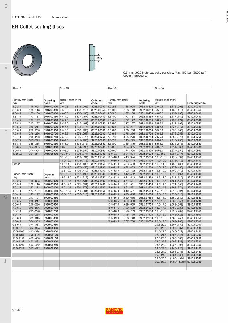
G 140
TOOLING SYSTEMS Accessories
E
F
G
J
D
G
RO
T - E
NG
TOOLING SYSTEMS Accessories
ER Collet sealing discs
0.5 mm (.020 inch) capacity per disc. Max 150 bar (2000 psi) coolant pressure.
Size 16 Size 25 Size 32 Size 40
Range, mm (inch) Ordering code
Range, mm (inch) Ordering code
Range, mm (inch) Ordering code
Range, mm (inch)Ordering codedmt dmt dmt dmt
3.0-2.5 (.118-.098) 3916.00300 3.0-2.5 (.118-.098) 3925.00300 3.0-2.5 (.118-.098) 3932.00300 3.0-2.5 (.118-.098) 3940.003003.5-3.0 (.138-.118) 3916.00350 3.5-3.0 (.138-.118) 3925.00350 3.5-3.0 (.138-.118) 3932.00350 3.5-3.0 (.138-.118) 3940.003504.0-3.5 (.157-.138) 3916.00400 4.0-3.5 (.157-.138) 3925.00400 4.0-3.5 (.157-.138) 3932.00400 4.0-3.5 (.157-.138) 3940.004004.5-4.0 (.177-.157) 3916.00450 4.5-4.0 (.177-.157) 3925.00450 4.5-4.0 (.177-.157) 3932.00450 4.5-4.0 (.177-.157) 3940.004505.0-4.5 (.197-.177) 3916.00500 5.0-4.5 (.197-.177) 3925.00500 5.0-4.5 (.197-.177) 3932.00500 5.0-4.5 (.197-.177) 3940.005005.5-5.0 (.217-.197) 3916.00550 5.5-5.0 (.217-.197) 3925.00550 5.5-5.0 (.217-.197) 3932.00550 5.5-5.0 (.217-.197) 3940.005506.0-5.5 (.236-.217) 3916.00600 6.0-5.5 (.236-.217) 3925.00600 6.0-5.5 (.236-.217) 3932.00600 6.0-5.5 (.236-.217) 3940.006006.5-6.0 (.256-.236) 3916.00650 6.5-6.0 (.256-.236) 3925.00650 6.5-6.0 (.256-.236) 3932.00650 6.5-6.0 (.256-.236) 3940.006507.0-6.5 (.276-.256) 3916.00700 7.0-6.5 (.276-.256) 3925.00700 7.0-6.5 (.276-.256) 3932.00700 7.0-6.5 (.276-.256) 3940.007007.5-7.0 (.295-.276) 3916.00750 7.5-7.0 (.295-.276) 3925.00750 7.5-7.0 (.295-.276) 3932.00750 7.5-7.0 (.295-.276) 3940.007508.0-7.5 (.315-.295) 3916.00800 8.0-7.5 (.315-.295) 3925.00800 8.0-7.5 (.315-.295) 3932.00800 8.0-7.5 (.315-.295) 3940.008008.5-8.0 (.335-.315) 3916.00850 8.5-8.0 (.335-.315) 3925.00850 8.5-8.0 (.335-.315) 3932.00850 8.5-8.0 (.335-.315) 3940.008509.0-8.5 (.354-.335) 3916.00900 9.0-8.5 (.354-.335) 3925.00900 9.0-8.5 (.354-.335) 3932.00900 9.0-8.5 (.354-.335) 3940.009009.5-9.0 (.374-.354) 3916.00950 9.5-9.0 (.374-.354) 3925.00950 9.5-9.0 (.374-.354) 3932.00950 9.5-9.0 (.374-.354) 3940.0095010.0-9.5 (.394-.374) 3916.01000 10.0-9.5 (.394-.374) 3925.01000 10.0-9.5 (.394-.374) 3932.01000 10.0-9.5 (.394-.374) 3940.01000
10.5-10.0 (.413-.394) 3925.01050 10.5-10.0 (.413-.394) 3932.01050 10.5-10.0 (.413-.394) 3940.0105011.0-10.5 (.433-.413) 3925.01100 11.0-10.5 (.433-.413) 3932.01100 11.0-10.5 (.433-.413) 3940.01100
Size 20 11.5-11.0 (.453-.433) 3925.01150 11.5-11.0 (.453-.433) 3932.01150 11.5-11.0 (.453-.433) 3940.0115012.0-11.5 (.472-.453) 3925.01200 12.0-11.5 (.472-.453) 3932.01200 12.0-11.5 (.472-.453) 3940.01200
Range, mm (inch) Ordering code
12.5-12.0 (.492-.472) 3925.01250 12.5-12.0 (.492-.472) 3932.01250 12.5-12.0 (.492-.472) 3940.0125013.0-12.5 (.512-.492) 3925.01300 13.0-12.5 (.512-.492) 3932.01300 13.0-12.5 (.512-.492) 3940.01300
dmt 13.5-13.0 (.531-.512) 3925.01350 13.5-13.0 (.531-.512) 3932.01350 13.5-13.0 (.531-.512) 3940.013503.0-2.5 (.118-.098) 3920.00300 14.0-13.5 (.551-.531) 3925.01400 14.0-13.5 (.551-.531) 3932.01400 14.0-13.5 (.551-.531) 3940.014003.5-3.0 (.138-.118) 3920.00350 14.5-14.0 (.571-.551) 3925.01450 14.5-14.0 (.571-.551) 3932.01450 14.5-14.0 (.571-.551) 3940.014504.0-3.5 (.157-.138) 3920.00400 15.0-14.5 (.591-.571) 3925.01500 15.0-14.5 (.591-.571) 3932.01500 15.0-14.5 (.591-.571) 3940.015004.5-4.0 (.177-.157) 3920.00450 15.5-15.0 (.610-.591) 3925.01550 15.5-15.0 (.610-.591) 3932.01550 15.5-15.0 (.610-.591) 3940.015505.0-4.5 (.197-.177) 3920.00500 16.0-15.5 (.630-.610) 3925.01600 16.0-15.5 (.630-.610) 3932.01600 16.0-15.5 (.630-.610) 3940.016005.5-5.0 (.217-.197) 3920.00550 16.5-16.0 (.650-.630) 3932.01650 16.5-16.0 (.650-.630) 3940.016506.0-5.5 (.236-.217) 3920.00600 17.0-16.5 (.669-.650) 3932.01700 17.0-16.5 (.669-.650) 3940.017006.5-6.0 (.256-.236) 3920.00650 17.5-17.0 (.689-.669) 3932.01750 17.5-17.0 (.689-.669) 3940.017507.0-6.5 (.276-.256) 3920.00700 18.0-17.5 (.709-.689) 3932.01800 18.0-17.5 (.709-.689) 3940.018007.5-7.0 (.295-.276) 3920.00750 18.5-18.0 (.728-.709) 3932.01850 18.5-18.0 (.728-.709) 3940.018508.0-7.5 (.315-.295) 3920.00800 19.0-18.5 (.748-.728) 3932.01900 19.0-18.5 (.748-.728) 3940.019008.5-8.0 (.335-.315) 3920.00850 19.5-19.0 (.768-.748) 3932.01950 19.5-19.0 (.768-.748) 3940.019509.0-8.5 (.354-.335) 3920.00900 20.0-19.5 (.787-.768) 3932.02000 20.0-19.5 (.787-.768) 3940.020009.5-9.0 (.374-.354) 3920.00950 20.5-20.0 (.807-.787) 3940.0205010.0-9.5 (.394-.374) 3920.01000 21.0-20.5 (.827-.807) 3940.0210010.5-10.0 (.413-.394) 3920.01050 21.5-21.0 (.846-.827) 3940.0215011.0-10.5 (433-.413) 3920.01100 22.0-21.5 (.866-.846) 3940.0220011.5-11.0 (.453-.433) 3920.01150 22.5-22.0 (.886-.866) 3940.0225012.0-11.5 (.472-.453) 3920.01200 23.0-22.5 (.906-.886) 3940.0230012.5-12.0 (.492-.472) 3920.01250 23.5-23.0 (.925-.906) 3940.0235013.0-12.5 (.512-.492) 3920.01300 24.0-23.5 (.945-.925) 3940.02400
24.5-24.0 (.965-.945) 3940.0245025.0-24.5 (.984-.965) 3940.0250025.5-25.0 (1.004-.984) 3940.0255026.0-25.5 (1.024-1.004) 3940.02600
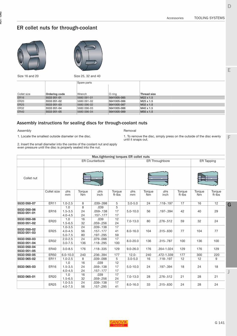
E
G 141
F
G
J
D
G
Accessories TOOLING SYSTEMS
RO
T -
EN
G
TOOLING SYSTEMS Accessories
ER collet nuts for through-coolant
Assembly instructions for sealing discs for through-coolant nuts
Size 16 and 20 Size 25, 32 and 40
Collet size Ordering code
Spare parts
Thread sizeWrench O-ringER16 5533 051-01 5680 091-01 5641005-085 M22 x 1.5ER20 5533 051-02 5680 091-02 5641005-086 M25 x 1.5ER25 5533 051-03 5680 096-02 5641005-087 M32 x 1.5ER32 5533 051-04 5680 096-03 5641005-088 M40 x 1.5ER40 5533 051-05 5680 096-04 5641005-089 M50 x 1.5
Assembly Removal
1. Locate the smallest outside diameter on the disc. 1. To remove the disc, simply press on the outside of the disc evenly until it snaps out.
2. Insert the small diameter into the centre of the coolant nut and apply even pressure until the disc is properly seated into the nut.
Max.tightening torques ER collet nutsER Counterbore ER Throughbore ER Tapping
Collet nut
Collet size dmtmm
Torque Nm
dmtinch
Torqueft-lbs
dmtmm
Torque Nm
dmtinch
Torqueft-lbs
Torque Nm
Torqueft-lbs
5533 050-07 ER11 1.0-2.5 8 .039-.098 5 3.0-5.0 24 .118-.197 17 16 12
5533 050-06 5533 051-01 ER16
1.0 8 .039 55.0-10.0 56 .197-.394 42 40 291.5-3.5 24 .059-.138 17
4.0-4.5 24 .157-.177 175533 050-08
ER201.0 16 .039 12
7.0-13.0 80 .276-.512 59 32 245533 051-02 1.5-6.5 32 .059-.256 24
5533 050-025533 051-03 ER25
1.0-3.5 24 .039-.138 178.0-16.0 104 .315-.630 77 104 774.0-4.5 56 .157-.177 41
5.0-7.5 80 .197-.295 595533 050-03
ER322.0-2.5 24 .079-.098 17
8.0-20.0 136 .315-.787 100 136 1005533 051-04 3.0-7.5 136 .118-.295 1005533 050-04
ER40 3.0-8.5 176 .118-.335 129 9.0-26.0 176 .354-1.024 129 176 1295533 051-055533 050-05 ER50 6.0-10.0 240 .236-.394 177 12.0- 240 .472-1.339 177 300 2205533 065-02 ER11 1.0-2.5 8 .039-.098 5 3.0-5.0 16 .118-.197 12 12 9
5533 065-03 ER161.0 16 .039 12
5.0-10.0 24 .197-.394 18 24 181.5-3.5 24 .059-.138 174.0-4.5 24 .157-.177 17
5533 065-01 ER201.0 16 .039 17
7.0-13.0 28 .276-.512 21 28 211.5-6.5 32 .059-.256 24
ER251.0-3.5 24 .039-.138 17
8.0-16.0 33 .315-.630 24 28 244.0-7.5 56 .157-.295 41
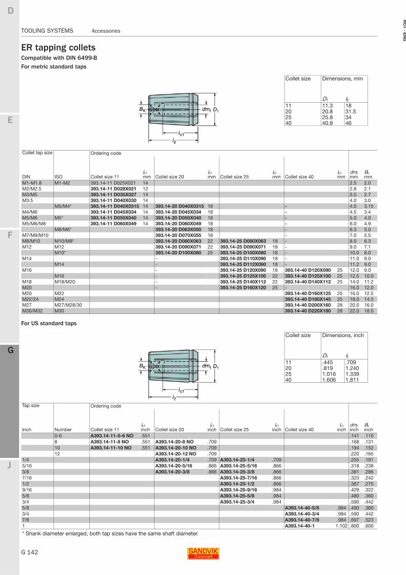
G 142
TOOLING SYSTEMS Accessories
E
F
G
J
D
G
RO
T - E
NG
TOOLING SYSTEMS Accessories
ER tapping colletsCompatible with DIN 6499-BFor metric standard taps
For US standard taps
Collet size Dimensions, mm
D1 l211 11.3 1820 20.8 31.525 25.8 3440 40.8 46
Collet tap size Ordering code
DIN ISO Collet size 11lc1mm Collet size 20
lc1mm Collet size 25
lc1mm Collet size 40
lc1mm
dmtmm
Bkmm
M1-M1.8 M1-M2 393.14-11 D025X021 14 2.5 2.0M2/M2.5 393.14-11 D028X021 12 2.8 2.1M3/M5 393.14-11 D035X027 14 3.5 2.7M3.5 393.14-11 D040X030 14 4.0 3.0
M5/M4* 393.14-11 D040X0315 14 393.14-20 D040X0315 18 - 4.0 3.15M4/M6 393.14-11 D045X034 14 393.14-20 D045X034 18 - 4.5 3.4M5/M6 M5* 393.14-11 D050X040 14 393.14-20 D050X040 18 - 5.0 4.0M5/M6/M8 393.14-11 D060X049 14 393.14-20 D060X049 18 - 6.0 4.9
M8/M6* 393.14-20 D063X050 18 - 6.3 5.0M7/M9/M10 393.14-20 D070X055 18 - 7.0 5.5M8/M10 M10/M8* 393.14-20 D080X063 22 393.14-25 D080X063 18 - 8.0 6.3M12 M12 393.14-20 D090X071 22 393.14-25 D090X071 18 - 9.0 7.1
M10* 393.14-20 D100X080 25 393.14-25 D100X080 18 - 10.0 8.0M14 - 393.14-25 D110X090 18 - 11.0 9.0
M14 - 393.14-25 D112X090 18 - 11.2 9.0M16 - 393.14-25 D120X090 18 393.14-40 D120X090 25 12.0 9.0
M16 - 393.14-25 D125X100 22 393.14-40 D125X100 25 12.5 10.0M18 M18/M20 - 393.14-25 D140X112 22 393.14-40 D140X112 25 14.0 11.2M20 - 393.14-25 D160X120 25 - 16.0 12.0M20 M22 393.14-40 D160X125 25 16.0 12.5M22/24 M24 393.14-40 D180X145 25 18.0 14.5M27 M27/M28/30 393.14-40 D200X160 28 20.0 16.0M30/M32 M30 393.14-40 D220X180 28 22.0 18.0
Collet size Dimensions, inch
D1 l211 .445 .70920 .819 1.24025 1.016 1.33940 1.606 1.811
Tap size Ordering code
dmtinch
BkinchInch Number Collet size 11
lc1inch Collet size 20
lc1inch Collet size 25
lc1inch Collet size 40
lc1inch
0-6 A393.14-11-0-6 NO .551 .141 .1108 A393.14-11-8 NO .551 A393.14-20-8 NO .709 .168 .13110 A393.14-11-10 NO .551 A393.14-20-10 NO .709 .194 .15212 A393.14-20-12 NO .709 .220 .165
1/4 A393.14-20-1/4 .709 A393.14-25-1/4 .709 .255 .1915/16 A393.14-20-5/16 .866 A393.14-25-5/16 .866 .318 .2383/8 A393.14-20-3/8 .866 A393.14-25-3/8 .866 .381 .2867/16 A393.14-25-7/16 .866 .323 .2421/2 A393.14-25-1/2 .866 .367 .2759/16 A393.14-25-9/16 .984 .429 .3225/8 A393.14-25-5/8 .984 .480 .3603/4 A393.14-25-3/4 .984 .590 .4425/8 A393.14-40-5/8 .984 .480 .3603/4 A393.14-40-3/4 .984 .590 .4427/8 A393.14-40-7/8 .984 .697 .5231 A393.14-40-1 1.102 .800 .600
* Shank diameter enlarged, both tap sizes have the same shaft diameter.
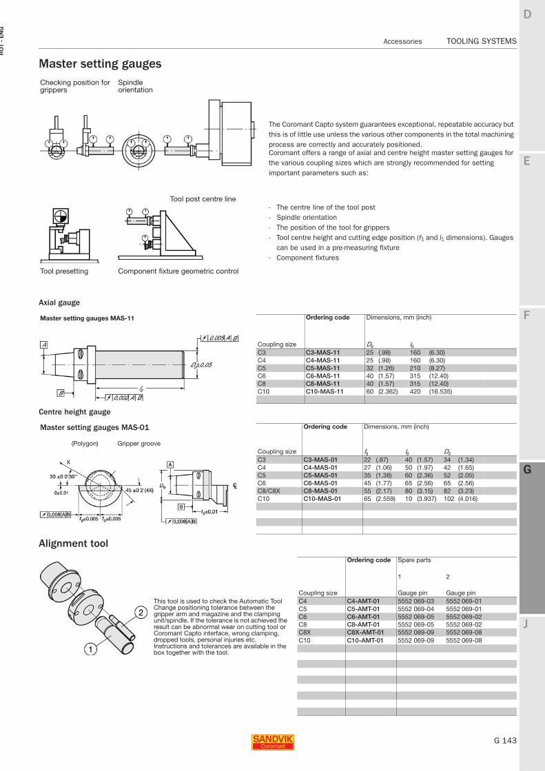
E
G 143
F
G
J
D
G
Accessories TOOLING SYSTEMS
RO
T -
EN
G
TOOLING SYSTEMS Accessories
Master setting gauges
Axial gauge
Centre height gauge
Alignment tool
Checking position for grippers
Spindle orientation
The Coromant Capto system guarantees exceptional, repeatable accuracy but this is of little use unless the various other components in the total machining process are correctly and accurately positioned.Coromant offers a range of axial and centre height master setting gauges for the various coupling sizes which are strongly recommended for setting important parameters such as:
Tool post centre line- The centre line of the tool post - Spindle orientation- The position of the tool for grippers- Tool centre height and cutting edge position (f1 and l1 dimensions). Gauges
can be used in a pre-measuring fixture- Component fixtures
Tool presetting Component fixture geometric control
Master setting gauges MAS-11
Coupling size
Ordering code Dimensions, mm (inch)
Dg lgC3 C3-MAS-11 25 (.98) 160 (6.30)C4 C4-MAS-11 25 (.98) 160 (6.30)C5 C5-MAS-11 32 (1.26) 210 (8.27)C6 C6-MAS-11 40 (1.57) 315 (12.40)C8 C8-MAS-11 40 (1.57) 315 (12.40)C10 C10-MAS-11 60 (2.362) 420 (16.535)
Master setting gauges MAS-01
Coupling size
Ordering code Dimensions, mm (inch)
(Polygon) Gripper groovefg lg Dg
C3 C3-MAS-01 22 (.87) 40 (1.57) 34 (1.34)C4 C4-MAS-01 27 (1.06) 50 (1.97) 42 (1.65)C5 C5-MAS-01 35 (1.38) 60 (2.36) 52 (2.05)C6 C6-MAS-01 45 (1.77) 65 (2.56) 65 (2.56)C8/C8X C8-MAS-01 55 (2.17) 80 (3.15) 82 (3.23)C10 C10-MAS-01 65 (2.559) 10 (3.937) 102 (4.016)
Coupling size
Ordering code Spare parts
1 2
Gauge pin Gauge pinThis tool is used to check the Automatic Tool Change positioning tolerance between the gripper arm and magazine and the clamping unit/spindle. If the tolerance is not achieved the result can be abnormal wear on cutting tool or Coromant Capto interface, wrong clamping, dropped tools, personal injuries etc. Instructions and tolerances are available in the box together with the tool.
C4 C4-AMT-01 5552 069-03 5552 069-01C5 C5-AMT-01 5552 069-04 5552 069-01C6 C6-AMT-01 5552 069-05 5552 069-02C8 C8-AMT-01 5552 069-05 5552 069-02C8X C8X-AMT-01 5552 089-09 5552 069-08C10 C10-AMT-01 5552 069-09 5552 069-08
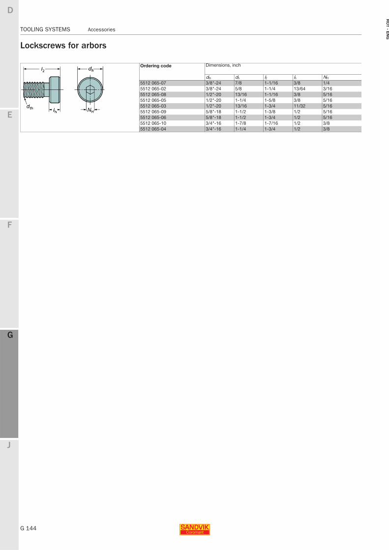
G 144
TOOLING SYSTEMS Accessories
E
F
G
J
D
G
RO
T - E
NG
TOOLING SYSTEMS Accessories
Lockscrews for arbors
Ordering code Dimensions, inch
dth dh l2 lh NH
5512 065-07 3/8"-24 7/8 1-1/16 3/8 1/45512 065-02 3/8"-24 5/8 1-1/4 13/64 3/165512 065-08 1/2"-20 13/16 1-1/16 3/8 5/165512 065-05 1/2"-20 1-1/4 1-5/8 3/8 5/165512 065-03 1/2"-20 13/16 1-3/4 11/32 5/165512 065-09 5/8"-18 1-1/2 1-3/8 1/2 5/165512 065-06 5/8"-18 1-1/2 1-3/4 1/2 5/165512 065-10 3/4"-16 1-7/8 1-7/16 1/2 3/85512 065-04 3/4"-16 1-1/4 1-3/4 1/2 3/8
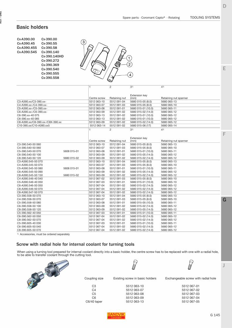
E
G 145
F
G
J
D
G
Spare parts - Coromant Capto® - Rotating TOOLING SYSTEMS
RO
T -
EN
G
TOOLING SYSTEMS Spare parts − Coromant Capto® − Rotating
Basic holders
Screw with radial hole for internal coolant for turning tools
Cx-A390.00Cx-A390.45Cx-A390.455Cx-A390.545
Cx-390.00Cx-390.55Cx-390.58Cx-390.140Cx-390.140HDCx-390.272Cx-390.369Cx-390.540Cx-390.555Cx-390.558
1 2 31) 41)
Centre screw Retaining nutExtension key (mm) Retaining nut spanner
C3-A390.xx/C3-390.xx- 5512 063-10 5512 091-04 5680 015-05 (8.0) 5680 065-13C4-A390.xx-/C4-390.xx- 5512 063-07 5512 091-03 5680 015-05 (8.0) 5680 065-10C5-A390.xx-/C5-390.xx- 5512 063-08 5512 091-01 5680 015-01 (10.0) 5680 065-11C6-A390.xx-/C6-390.xx- 5512 063-09 5512 091-02 5680 015-02 (14.0) 5680 065-12C6-390.xx-40 075 5512 063-13 5512 091-02 5680 015-01 (10.0) 5680 065-12C6-390.xx-40 085 5512 063-13 5512 091-02 5680 015-01 (10.0) 5680 065-12C8-A390.xx/C8-390.xx-/C8X-390.xx 5512 063-09 5512 091-02 5680 015-02 (14.0) 5680 065-12C10-390.xx/C10-A390.xx5 5512 063-14 5512 091-02 5680 015-06 (17) 5680 065-14
1 2 31) 41)
Centre screw Retaining nutExtension key (mm) Retaining nut spanner
C3-390.540-50 060 5512 063-10 5512 091-04 5680 015-05 (8.0) 5680 065-13C4-390.540-50 060 5512 063-07 5512 091-03 5680 015-05 (8.0) 5680 065-10C5-390.540-50 070 5608 015-01 5512 063-08 5512 091-01 5680 015-01 (10.0) 5680 065-11C6-390.540-50 100 5512 063-09 5512 091-02 5680 015-05 (14.0) 5680 065-12C8-390.540-50 120 5680 015-02 5512 063-09 5512 091-02 5680 015-02 (14.0) 5680 065-12C3-A390.545-50 070 5512 063-10 5512 091-04 5680 015-05 (8.0) 5680 065-13C4-A390.545-50 070 5512 063-07 5512 091-03 5680 015-05 (8.0) 5680 065-10C5-A390.545-50 080 5608 015-01 5512 063-08 5512 091-01 5680 015-01 (10.0) 5680 065-11C6-A390.545-50 090 5512 063-09 5512 091-02 5680 015-05 (14.0) 5680 065-12C8-A390.545-50 150 5680 015-02 5512 063-09 5512 091-02 5680 015-02 (14.0) 5680 065-12C4-A390.546-40 040 5512 067-02 5512 091-03 5680 015-05 (8.0) 5680 065-10C5-A390.546-40 050 5512 067-03 5512 091-01 5680 015-01 (10.0) 5680 065-10C6-A390.546-50 050 5512 067-04 5512 091-02 5680 015-02 (14.0) 5680 065-12C8-A390.546-50 070 5512 067-04 5512 091-02 5680 015-02 (14.0) 5680 065-12C8-A390.547-50 070 5512 067-04 5512 091-02 5680 015-02 (14.0) 5680 065-12C3-390.558-50 070 5512 063-10 5512 091-04 5680 015-05 (8.0) 5680 065-13C4-390.558-50 070 5512 063-07 5512 091-03 5680 015-05 (8.0) 5680 065-10C5-390.558-50 080 5512 063-08 5512 091-01 5680 015-05 (10.0) 5680 065-11C6-390.558-50 100 5512 063-09 5512 091-02 5680 015-02 (14.0) 5680 065-12C8-390.558-50 120 5512 063-09 5512 091-02 5680 015-05 (14.0) 5680 065-12C5-390.562-40 050 5512 067-03 5512 091-01 5680 015-01 (10.0) 5680 065-11C6-390.562-50 050 5512 067-04 5512 091-02 5680 015-02 (14.0) 5680 065-12C8-390.562-50 070 5512 067-04 5512 091-02 5680 015-02 (14.0) 5680 065-12C5-390.605-40 030 5512 067-03 5512 091-01 5680 015-01 (10.0) 5680 065-11C6-390.605-50 040 5512 067-04 5512 091-02 5680 015-02 (14.0) 5680 065-12C8-390.605-50 070 5512 067-04 5512 091-02 5680 015-02 (14.0) 5680 065-121) Accessories, must be ordered separately
When using a turning tool prepared for internal coolant directly into a basic holder, the centre screw has to be replaced with one with a radial hole, to be able to transfer coolant through the cutting tool.
Coupling size Existing screw in basic holders Exchangeable screw with radial hole
C3 5512 063-10 5512 067-01C4 5512 063-07 5512 067-02C5 5512 063-08 5512 067-03C6 5512 063-09 5512 067-04
C6/40 taper 5512 063-13 5512 067-05
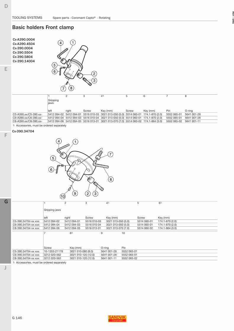
G 146
TOOLING SYSTEMS Spare parts - Coromant Capto® - Rotating
E
F
G
J
D
G
RO
T - E
NG
TOOLING SYSTEMS Spare parts − Coromant Capto® − Rotating
Basic holders Front clamp
Cx-390.34704
Cx-A390.0004Cx-A390.4504Cx-390.0004Cx-390.5504Cx-390.5804Cx-390.14004
1 2 3 41) 5 6 7 8
Gripping jaws
left right Screw Key (mm) Screw Key (mm) Pin O-ringC5-A390.xx/C5-390.xx- 5412 094-02 5412 094-01 5516 010-03 3021 013-050 (5.0) 5514 060-01 174.1-870 (2.0) 5552 065-01 5641 001-28C6-A390.xx/C6-390.xx- 5412 094-04 5412 094-03 5516 010-04 3021 013-050 (5.0) 5514 060-01 174.1-870 (2.0) 5552 065-01 5641 001-28C8-A390.xx/C8-390.xx- 5412 094-06 5412 094-05 5516 013-01 3021 013-070 (7.0) 5514 060-02 174.1-864 (3.0) 5552 065-02 5641 001-111) Accessories, must be ordered separately
1 2 3 41) 5 61)
Gripping jaws
left right Screw Key (mm) Screw Key (mm)C5-390.34704-xx xxx 5412 094-02 5412 094-01 5516 010-03 3021 013-050 (5.0) 5514 060-01 174.1-870 (2.0)C6-390.34704-xx xxx 5412 094-04 5412 094-03 5516 010-04 3021 013-050 (5.0) 5514 060-01 174.1-870 (2.0)C8-390.34704-xx xxx 5412 094-06 5412 094-05 5516 013-01 3021 013-070 (7.0) 5514 060-02 174.1-864 (3.0)
7 81) 9 10
Screw Key (mm) O-ring PinC5-390.34704-xx xxx 10-1353-21178 3021 010-080 (8.0) 5641 001-28 5552 065-01C6-390.34704-xx xxx 3212 020-562 3021 010-120 (12.0) 5641 001-28 5552 065-01C8-390.34704-xx xxx 3212 020-562 3021 010-120 (12.0) 5641 001-11 5552 065-021) Accessories, must be ordered separately
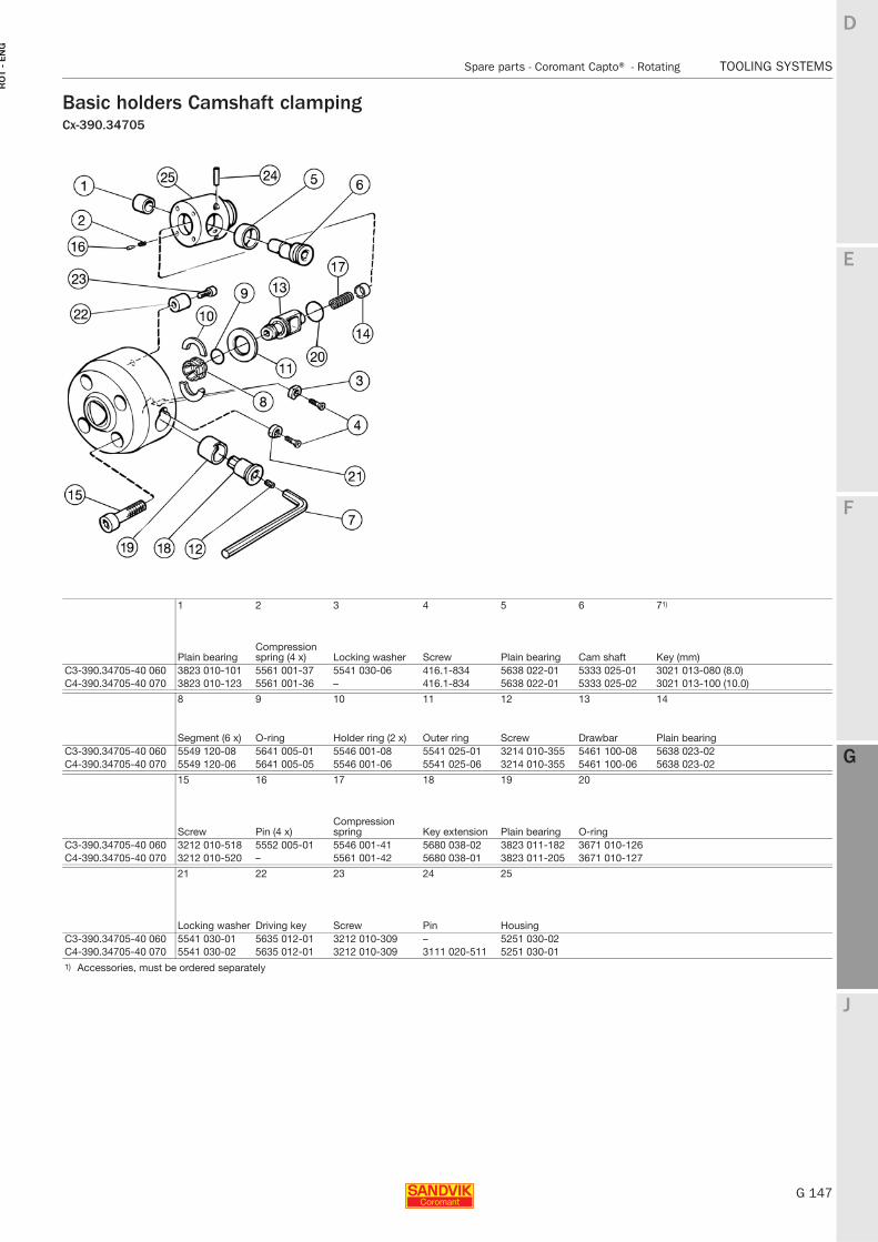
E
G 147
F
G
J
D
G
Spare parts - Coromant Capto® - Rotating TOOLING SYSTEMS
RO
T -
EN
G
TOOLING SYSTEMS Spare parts − Coromant Capto® − Rotating
Basic holders Camshaft clampingCx-390.34705
1 2 3 4 5 6 71)
Plain bearingCompression spring (4 x) Locking washer Screw Plain bearing Cam shaft Key (mm)
C3-390.34705-40 060 3823 010-101 5561 001-37 5541 030-06 416.1-834 5638 022-01 5333 025-01 3021 013-080 (8.0)C4-390.34705-40 070 3823 010-123 5561 001-36 – 416.1-834 5638 022-01 5333 025-02 3021 013-100 (10.0)
8 9 10 11 12 13 14
Segment (6 x) O-ring Holder ring (2 x) Outer ring Screw Drawbar Plain bearingC3-390.34705-40 060 5549 120-08 5641 005-01 5546 001-08 5541 025-01 3214 010-355 5461 100-08 5638 023-02C4-390.34705-40 070 5549 120-06 5641 005-05 5546 001-06 5541 025-06 3214 010-355 5461 100-06 5638 023-02
15 16 17 18 19 20
Screw Pin (4 x)Compression spring Key extension Plain bearing O-ring
C3-390.34705-40 060 3212 010-518 5552 005-01 5546 001-41 5680 038-02 3823 011-182 3671 010-126C4-390.34705-40 070 3212 010-520 – 5561 001-42 5680 038-01 3823 011-205 3671 010-127
21 22 23 24 25
Locking washer Driving key Screw Pin HousingC3-390.34705-40 060 5541 030-01 5635 012-01 3212 010-309 – 5251 030-02C4-390.34705-40 070 5541 030-02 5635 012-01 3212 010-309 3111 020-511 5251 030-011) Accessories, must be ordered separately
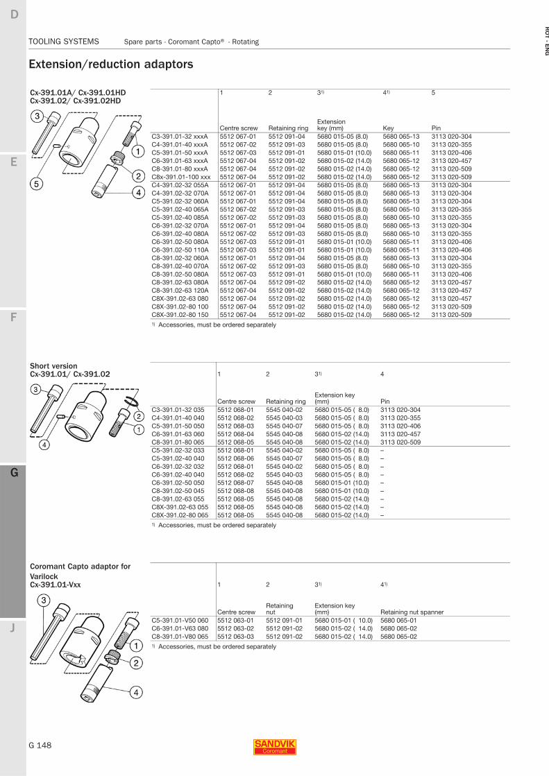
G 148
TOOLING SYSTEMS Spare parts - Coromant Capto® - Rotating
E
F
G
J
D
G
RO
T - E
NG
TOOLING SYSTEMS Spare parts − Coromant Capto® − Rotating
Extension/reduction adaptors
Cx-391.01A/ Cx-391.01HD 1 2 31) 41) 5Cx-391.02/ Cx-391.02HD
Centre screw Retaining ringExtension key (mm) Key Pin
C3-391.01-32 xxxA 5512 067-01 5512 091-04 5680 015-05 (8.0) 5680 065-13 3113 020-304C4-391.01-40 xxxA 5512 067-02 5512 091-03 5680 015-05 (8.0) 5680 065-10 3113 020-355C5-391.01-50 xxxA 5512 067-03 5512 091-01 5680 015-01 (10.0) 5680 065-11 3113 020-406C6-391.01-63 xxxA 5512 067-04 5512 091-02 5680 015-02 (14.0) 5680 065-12 3113 020-457C8-391.01-80 xxxA 5512 067-04 5512 091-02 5680 015-02 (14.0) 5680 065-12 3113 020-509C8x-391.01-100 xxx 5512 067-04 5512 091-02 5680 015-02 (14.0) 5680 065-12 3113 020-509C4-391.02-32 055A 5512 067-01 5512 091-04 5680 015-05 (8.0) 5680 065-13 3113 020-304C4-391.02-32 070A 5512 067-01 5512 091-04 5680 015-05 (8.0) 5680 065-13 3113 020-304C5-391.02-32 060A 5512 067-01 5512 091-04 5680 015-05 (8.0) 5680 065-13 3113 020-304C5-391.02-40 065A 5512 067-02 5512 091-03 5680 015-05 (8.0) 5680 065-10 3113 020-355C5-391.02-40 085A 5512 067-02 5512 091-03 5680 015-05 (8.0) 5680 065-10 3113 020-355C6-391.02-32 070A 5512 067-01 5512 091-04 5680 015-05 (8.0) 5680 065-13 3113 020-304C6-391.02-40 080A 5512 067-02 5512 091-03 5680 015-05 (8.0) 5680 065-10 3113 020-355C6-391.02-50 080A 5512 067-03 5512 091-01 5680 015-01 (10.0) 5680 065-11 3113 020-406C6-391.02-50 110A 5512 067-03 5512 091-01 5680 015-01 (10.0) 5680 065-11 3113 020-406C8-391.02-32 060A 5512 067-01 5512 091-04 5680 015-05 (8.0) 5680 065-13 3113 020-304C8-391.02-40 070A 5512 067-02 5512 091-03 5680 015-05 (8.0) 5680 065-10 3113 020-355C8-391.02-50 080A 5512 067-03 5512 091-01 5680 015-01 (10.0) 5680 065-11 3113 020-406C8-391.02-63 080A 5512 067-04 5512 091-02 5680 015-02 (14.0) 5680 065-12 3113 020-457C8-391.02-63 120A 5512 067-04 5512 091-02 5680 015-02 (14.0) 5680 065-12 3113 020-457C8X-391.02-63 080 5512 067-04 5512 091-02 5680 015-02 (14.0) 5680 065-12 3113 020-457C8X-391.02-80 100 5512 067-04 5512 091-02 5680 015-02 (14.0) 5680 065-12 3113 020-509C8X-391.02-80 150 5512 067-04 5512 091-02 5680 015-02 (14.0) 5680 065-12 3113 020-5091) Accessories, must be ordered separately
Short versionCx-391.01/ Cx-391.02 1 2 31) 4
Centre screw Retaining ringExtension key (mm) Pin
C3-391.01-32 035 5512 068-01 5545 040-02 5680 015-05 ( 8.0) 3113 020-304C4-391.01-40 040 5512 068-02 5545 040-03 5680 015-05 ( 8.0) 3113 020-355C5-391.01-50 050 5512 068-03 5545 040-07 5680 015-05 ( 8.0) 3113 020-406C6-391.01-63 060 5512 068-04 5545 040-08 5680 015-02 (14.0) 3113 020-457C8-391.01-80 065 5512 068-05 5545 040-08 5680 015-02 (14.0) 3113 020-509C5-391.02-32 033 5512 068-01 5545 040-02 5680 015-05 ( 8.0) –C5-391.02-40 040 5512 068-06 5545 040-07 5680 015-05 ( 8.0) –C6-391.02-32 032 5512 068-01 5545 040-02 5680 015-05 ( 8.0) –C6-391.02-40 040 5512 068-02 5545 040-03 5680 015-05 ( 8.0) –C6-391.02-50 050 5512 068-07 5545 040-08 5680 015-01 (10.0) –C8-391.02-50 045 5512 068-08 5545 040-08 5680 015-01 (10.0) –C8-391.02-63 055 5512 068-05 5545 040-08 5680 015-02 (14.0) –C8X-391.02-63 055 5512 068-05 5545 040-08 5680 015-02 (14.0) –C8X-391.02-80 065 5512 068-05 5545 040-08 5680 015-02 (14.0) –1) Accessories, must be ordered separately
Coromant Capto adaptor for VarilockCx-391.01-Vxx 1 2 31) 41)
Centre screwRetaining nut
Extension key (mm) Retaining nut spanner
C5-391.01-V50 060 5512 063-01 5512 091-01 5680 015-01 ( 10.0) 5680 065-01C6-391.01-V63 080 5512 063-02 5512 091-02 5680 015-02 ( 14.0) 5680 065-02C8-391.01-V80 065 5512 063-03 5512 091-02 5680 015-02 ( 14.0) 5680 065-021) Accessories, must be ordered separately
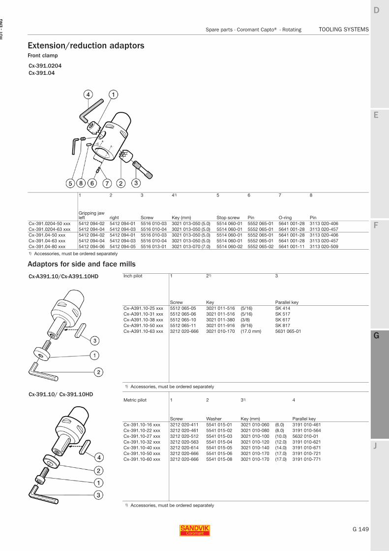
E
G 149
F
G
J
D
G
Spare parts - Coromant Capto® - Rotating TOOLING SYSTEMS
RO
T -
EN
G
TOOLING SYSTEMS Spare parts − Coromant Capto® − Rotating
Extension/reduction adaptorsFront clamp
Adaptors for side and face mills
Cx-391.0204Cx-391.04
1 2 3 41) 5 6 7 8
Gripping jaw left right Screw Key (mm) Stop screw Pin O-ring Pin
Cx-391.0204-50 xxx 5412 094-02 5412 094-01 5516 010-03 3021 013-050 (5.0) 5514 060-01 5552 065-01 5641 001-28 3113 020-406Cx-391.0204-63 xxx 5412 094-04 5412 094-03 5516 010-04 3021 013-050 (5.0) 5514 060-01 5552 065-01 5641 001-28 3113 020-457Cx-391.04-50 xxx 5412 094-02 5412 094-01 5516 010-03 3021 013-050 (5.0) 5514 060-01 5552 065-01 5641 001-28 3113 020-406Cx-391.04-63 xxx 5412 094-04 5412 094-03 5516 010-04 3021 013-050 (5.0) 5514 060-01 5552 065-01 5641 001-28 3113 020-457Cx-391.04-80 xxx 5412 094-06 5412 094-05 5516 013-01 3021 013-070 (7.0) 5514 060-02 5552 065-02 5641 001-11 3113 020-5091) Accessories, must be ordered separately
Cx-A391.10/Cx-A391.10HD Inch pilot 1 21) 3
Screw Key Parallel keyCx-A391.10-25 xxx 5512 065-05 3021 011-516 (5/16) SK 414Cx-A391.10-31 xxx 5512 065-06 3021 011-516 (5/16) SK 517Cx-A391.10-38 xxx 5512 065-10 3021 011-380 (3/8) SK 617Cx-A391.10-50 xxx 5512 065-11 3021 011-916 (9/16) SK 817Cx-A391.10-63 xxx 3212 020-666 3021 010-170 (17.0 mm) 5631 065-01
1) Accessories, must be ordered separately
Cx-391.10/ Cx-391.10HDMetric pilot 1 2 31) 4
Screw Washer Key (mm) Parallel keyCx-391.10-16 xxx 3212 020-411 5541 015-01 3021 010-060 (6.0) 3191 010-461Cx-391.10-22 xxx 3212 020-461 5541 015-02 3021 010-080 (8.0) 3191 010-564Cx-391.10-27 xxx 3212 020-512 5541 015-03 3021 010-100 (10.0) 5632 010-01Cx-391.10-32 xxx 3212 020-563 5541 015-04 3021 010-120 (12.0) 3191 010-621Cx-391.10-40 xxx 3212 020-614 5541 015-05 3021 010-140 (14.0) 3191 010-671Cx-391.10-50 xxx 3212 020-666 5541 015-06 3021 010-170 (17.0) 3191 010-721Cx-391.10-60 xxx 3212 020-666 5541 015-08 3021 010-170 (17.0) 3191 010-771
1) Accessories, must be ordered separately
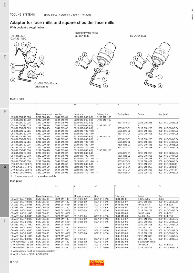
G 150
TOOLING SYSTEMS Spare parts - Coromant Capto® - Rotating
E
F
G
J
D
G
RO
T - E
NG
TOOLING SYSTEMS Spare parts − Coromant Capto® − Rotating
Adaptor for face mills and square shoulder face millsWith coolant through arbor
Metric pilot
Inch pilot
Round driving keys:Cx-391.05CCx-A391.05C
Cx-391.05C Cx-A391.05C
1 2 31) 4 5 6 71)
Mounting screw Washer Key (mm) Driving ring Driving key Screw Key (mm)C3-391.05C-16 030 3212 020-414 5541 015-01 3021 010-060 (6.0) 3193 010-160 - - -C4-391.05C-16 032 3212 020-414 5541 015-01 3021 010-060 (6.0) 3193 010-160 - - -C4-391.05C-22 025 3212 020-464 5541 015-02 3021 010-080 (8.0) - 5631 011-01 3213 010-258 3021 010-030 (3.0)C5-391.05C-16 035 3212 020-414 5541 015-01 3021 010-060 (6.0) 3193 010-160 - - -C5-391.05C-22 025 3212 020-464 5541 015-02 3021 010-080 (8.0) - 5635 025-01 3212 010-258 3021 010-030 (3.0)C5-391.05C-27 025 3212 020-514 5541 015-03 3021 010-100 (10.0) - 5635 025-02 3212 010-308 3021 010-040 (4.0)C5-391.05C-32 040 3212 020-564 5541 015-04 3021 010-120 (12.0) - 5631 010-04 3212 010-308 3021 010-040 (4.0)C6-391.05C-16 040 3212 020-414 5541 015-01 3021 010-060 (6.0) 3193 010-160 - - -C6-391.05C-22 025 3212 020-464 5541 015-02 3021 010-080 (8.0) - 5635 025-01 3212 010-258 3021 010-030 (3.0)C6-391.05C-27 025 3212 020-514 5541 015-03 3021 010-100 (10.0) - 5635 025-02 3212 010-308 3021 010-040 (4.0)C6-391.05C-32 025 3212 020-564 5541 015-04 3021 010-120 (12.0) - 5635 025-03 3212 010-358 3021 010-050 (5.0)C6-391.05C-40 040 3212 020-614 5541 015-05 3021 010-140 (14.0) - 5631 010-02 3212 010-358 3021 010-050 (5.0)C8-391.05C-16 050 3212 020-414 5541 015-01 3021 010-060 (6.0) 3193 010-160 - - -C8-391.05C-22 030 3212 020-464 5541 015-02 3021 010-080 (8.0) - 5635 025-01 3212 010-258 3021 010-030 (3.0)C8-391.05C-27 030 3212 020-514 5541 015-03 3021 010-100 (10.0) - 5635 025-02 3212 010-308 3021 010-040 (4.0)C8-391.05C-32 030 3212 020-564 5541 015-04 3021 010-120 (12.0) - 5635 025-03 3212 010-358 3021 010-050 (5.0)C8-391.05C-40 030 3212 020-614 5541 015-05 3021 010-140 (14.0) - 5635 025-04 3212 020-409 3021 010-060 (6.0)C10-391.05C-22 075 3212 020-454 5541 015-02 3021 010-080 (8.0) - 5631 012-01 3212 010-258 3021 010-030(3.0)C10-391.05C-27 075 3212 020-514 5541 015-03 3021 010-100 (10.0) - 5631 010-01 3212 010-258 3021 010-030(3.0)C10-391.05C-32 075 3212 020-564 5541 015-04 3021 010-120 (12.0) - 5631 010-01 3212 010-308 3021 010-040(4.0)C10-391.05C-40 040 3212 020-614 5541 015-05 3021 010-140 (14.0) - 5635 025-04 3212 020-409 3021 010-060 (6.0)1) Accessories, must be ordered separately
1 31) 1 31) 5 6 71)
Mounting screw Key Mounting screw Key Drive key Screw KeyC3-A391.05C-19 030 5512 065-07 3021 011-140 5512 065-02 3021 011-316 5631 013-01 8-32 x 3/8M (9/64)C4-A391.05C-19 025 5512 065-07 3021 011-140 5512 065-02 3021 011-316 5635 025-07 3212 010-207 3021 010-025 (2.5)C4-A391.05C-25 035 5512 065-05 3021 011-5162) 5512 065-03 3021 011-516 5631 013-02 10-32 x 3/8 3021 011-532C5-A391.05C-19 025 5512 065-07 3021 011-140 5512 065-02 3021 011-316 5635 025-07 3212 010-207 3021 010-025 (2.5)C5-A391.05C-25 025 5512 065-05 3021 011-5162) 5512 065-03 3021 011-516 5635 025-06 3212 010-257 3021 010-030 (3.0)C5-A391.05C-31 040 5512 065-06 3021 011-5162) - - 5631 010-06 10-32 x 3/8 3021 011-532C5-A391.05C-38 045 5512 065-10 3021 011-380 5512 065-04 3021 011-380 5631 013-04 1/4-20 x 3/4 3021 011-316C6-A391.05C-19 030 5512 065-07 3021 011-140 5512 065-02 3021 011-316 5635 025-07 3212 010-207 3021 010-025 (2.5)C6-A391.05C-25 030 5512 065-05 3021 011-5162) 5512 065-03 3021 011-516 5635 025-06 3212 010-257 3021 010-030 (3.0)C6-A391.05C-31 030 5512 065-06 3021 011-5162) - - 5635 025-08 3212 010-308 3021 010-040 (4.0)C6-A391.05C-38 045 5512 065-10 3021 011-380 5512 065-04 3021 011-380 5631 013-04 1/4-20 x 3/4 3021 011-316C8-A391.05C-19 030 5512 065-07 3021 011-140 5512 065-02 3021 011-316 5635 025-07 3212 010-207 3021 010-025 (2.5)C8-A391.05C-25 030 5512 065-05 3021 011-5162) 5512 065-03 3021 011-516 5635 025-06 3212 010-257 3021 010-030 (3.0)C8-A391.05C-31 030 5512 065-06 3021 011-5162) - - 5635 025-08 3212 010-308 3021 010-040 (4.0)C8-A391.05C-38 030 5512 065-10 3021 011-380 5512 065-04 3021 011-380 5635 025-05 3212 010-409 3021 010-060 (6.0)C10-A391.05C-19 075 5512 065-07 3021 011-140 5512 065-02 3021 011-316 5631 013-03 8-32x3/8M (9/64)C10-A391.05C-25 075 5512 065-05 3021 011-516 5512 065-03 3021 011-516 5631 013-02 10-32x3/8 3021 011-532C10-A391.05C-38 040 5512 065-10 3021 011-380 5512 065-04 3021 011-380 5635 025-05 3212 010-409 3021 010-060 (6.0)1) Accessories, must be ordered separately 2) ANSI - Code = DIN 911-5/16 ZDLL
Cx-391.05C-16 xxxDriving ring
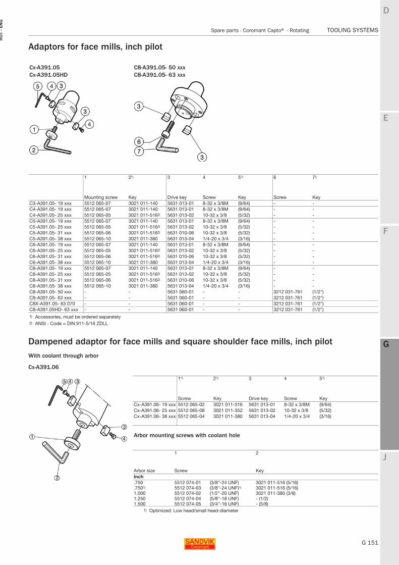
E
G 151
F
G
J
D
G
Spare parts - Coromant Capto® - Rotating TOOLING SYSTEMS
RO
T -
EN
G
TOOLING SYSTEMS Spare parts − Coromant Capto® − Rotating
Adaptors for face mills, inch pilot
Dampened adaptor for face mills and square shoulder face mills, inch pilotWith coolant through arbor
Cx-A391.06
Cx-A391.05Cx-A391.05HD
C8-A391.05- 50 xxxC8-A391.05- 63 xxx
1 21) 3 4 51) 6 7!)
Mounting screw Key Drive key Screw Key Screw KeyC3-A391.05- 19 xxx 5512 065-07 3021 011-140 5631 013-01 8-32 x 3/8M (9/64) - -C4-A391.05- 19 xxx 5512 065-07 3021 011-140 5631 013-01 8-32 x 3/8M (9/64) - -C4-A391.05- 25 xxx 5512 065-05 3021 011-5162) 5631 013-02 10-32 x 3/8 (5/32) - -C5-A391.05- 19 xxx 5512 065-07 3021 011-140 5631 013-01 8-32 x 3/8M (9/64) - -C5-A391.05- 25 xxx 5512 065-05 3021 011-5162) 5631 013-02 10-32 x 3/8 (5/32) - -C5-A391.05- 31 xxx 5512 065-06 3021 011-5162) 5631 010-06 10-32 x 3/8 (5/32) - -C5-A391.05- 38 xxx 5512 065-10 3021 011-380 5631 013-04 1/4-20 x 3/4 (3/16) - -C6-A391.05- 19 xxx 5512 065-07 3021 011-140 5631 013-01 8-32 x 3/8M (9/64) - -C6-A391.05- 25 xxx 5512 065-05 3021 011-5162) 5631 013-02 10-32 x 3/8 (5/32) - -C6-A391.05- 31 xxx 5512 065-06 3021 011-5162) 5631 010-06 10-32 x 3/8 (5/32) - -C6-A391.05- 38 xxx 5512 065-10 3021 011-380 5631 013-04 1/4-20 x 3/4 (3/16) - -C8-A391.05- 19 xxx 5512 065-07 3021 011-140 5631 013-01 8-32 x 3/8M (9/64) - -C8-A391.05- 25 xxx 5512 065-05 3021 011-5162) 5631 013-02 10-32 x 3/8 (5/32) - -C8-A391.05- 31 xxx 5512 065-06 3021 011-5162) 5631 010-06 10-32 x 3/8 (5/32) - -C8-A391.05- 38 xxx 5512 065-10 3021 011-380 5631 013-04 1/4-20 x 3/4 (3/16) - -C8-A391.05- 50 xxx - - 5631 060-01 - - 3212 031-761 (1/2")C8-A391.05- 63 xxx - - 5631 060-01 - - 3212 031-761 (1/2")C8X-A391.05- 63 070 - - 5631 060-01 - - 3212 031-761 (1/2")C8-A391.05HD- 63 xxx - - 5631 060-01 - - 3212 031-761 (1/2")1) Accessories, must be ordered separately 2) ANSI - Code = DIN 911-5/16 ZDLL
11) 21) 3 4 51)
Screw Key Drive key Screw KeyCx-A391.06- 19 xxx 5512 065-02 3021 011-316 5631 013-01 8-32 x 3/8M (9/64)Cx-A391.06- 25 xxx 5512 065-08 3021 011-352 5631 013-02 10-32 x 3/8 (5/32)Cx-A391.06- 38 xxx 5512 065-04 3021 011-380 5631 013-04 1/4-20 x 3/4 (3/16)
Arbor mounting screws with coolant hole
1 2
Arbor size Screw KeyInch .750 5512 074-01 (3/8"-24 UNF) 3021 011-516 (5/16).7501) 5512 074-03 (3/8"-24 UNF)1) 3021 011-516 (5/16)1.000 5512 074-02 (1/2"-20 UNF) 3021 011-380 (3/8)1.250 5512 074-04 (5/8"-18 UNF) - (1/2)1.500 5512 074-05 (3/4"-16 UNF) - (5/8)
1) Optimized: Low head/small head-diameter
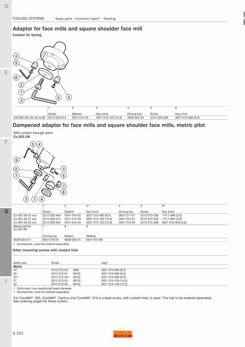
G 152
TOOLING SYSTEMS Spare parts - Coromant Capto® - Rotating
E
F
G
J
D
G
RO
T - E
NG
TOOLING SYSTEMS Spare parts − Coromant Capto® − Rotating
Adaptor for face mills and square shoulder face millCoolant for boring
Dampened adaptor for face mills and square shoulder face mills, metric pilot
Arbor mounting screws with coolant hole
1 2 3 4 5 6
Screw Washer Key (mm) Driving key Screw Key (mm)C8/C8X-391.05-40 xxxB 3212 020-614 5541 015-05 3021 010-140 (14.0) 5635 025-04 3212 020-409 3021 010-060 (6.0)
With coolant through arborCx-391.06
1 2 31) 4 5 61)
Screw Washer Key (mm) Driving key Screw Key (mm)Cx-391.06-22 xxx 3212 020-464 5541 015-02 3021 010-080 (8.0) 5631 011-01 3213 010-258 174.1-864 (3.0)Cx-391.06-27 xxx 3212 020-514 5541 015-03 3021 010-100 (10.0) 5631 010-01 3212 010-258 174.1-864 (3.0)Cx-391.06-32 xxx 3212 020-564 5541 015-04 3021 010-120 (12.0) 5631 010-04 3212 010-308 3021 010-040 (4.0)Sleeve set for Cx-391.06
7 8 9
Driving key Sleeve Washer5638 035-011 5631 016-01 5638 035-01 5541 015-091) Accessories, must be ordered separately
Arbor size Screw Key2)
Metric16 5512 073-03 (M8) 3021 010-060 (6.0)22 5512 073-01 (M10) 3021 010-080 (8.0)221) 5512 073-041) (M10) 3021 010-080 (8.0)27 5512 073-02 (M12) 3021 010-100 (10.0)32 5512 073-05 (M16) 3021 010-140 (12.0)1) Optimized: Low head/small head-diameter2) Accessories, must be ordered separately
For CoroMill® 365, CoroMill® Century and CoroMill® 210 a unique screw, with coolant hole, is used. This has to be ordered separately.See ordering pages for these cutters.
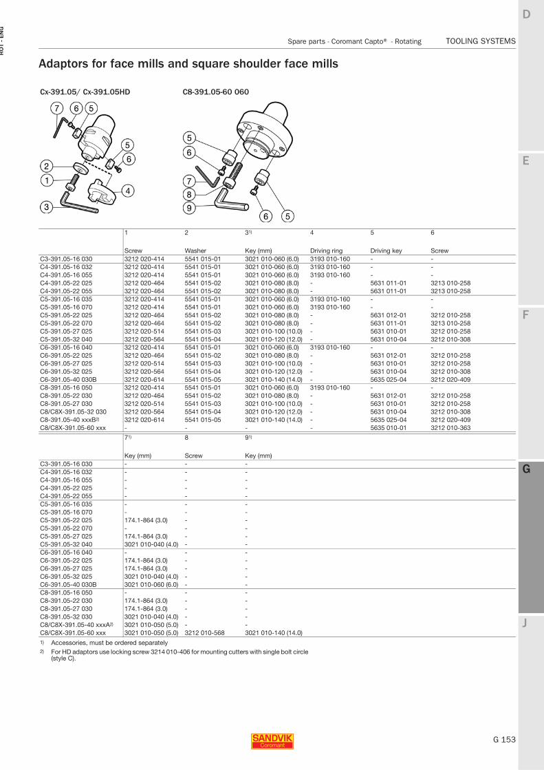
E
G 153
F
G
J
D
G
Spare parts - Coromant Capto® - Rotating TOOLING SYSTEMS
RO
T -
EN
G
TOOLING SYSTEMS Spare parts − Coromant Capto® − Rotating
Adaptors for face mills and square shoulder face mills
Cx-391.05/ Cx-391.05HD C8-391.05-60 060
1 2 31) 4 5 6
Screw Washer Key (mm) Driving ring Driving key ScrewC3-391.05-16 030 3212 020-414 5541 015-01 3021 010-060 (6.0) 3193 010-160 - -C4-391.05-16 032 3212 020-414 5541 015-01 3021 010-060 (6.0) 3193 010-160 - -C4-391.05-16 055 3212 020-414 5541 015-01 3021 010-060 (6.0) 3193 010-160 - -C4-391.05-22 025 3212 020-464 5541 015-02 3021 010-080 (8.0) - 5631 011-01 3213 010-258C4-391.05-22 055 3212 020-464 5541 015-02 3021 010-080 (8.0) - 5631 011-01 3213 010-258C5-391.05-16 035 3212 020-414 5541 015-01 3021 010-060 (6.0) 3193 010-160 - -C5-391.05-16 070 3212 020-414 5541 015-01 3021 010-060 (6.0) 3193 010-160 - -C5-391.05-22 025 3212 020-464 5541 015-02 3021 010-080 (8.0) - 5631 012-01 3212 010-258C5-391.05-22 070 3212 020-464 5541 015-02 3021 010-080 (8.0) - 5631 011-01 3213 010-258C5-391.05-27 025 3212 020-514 5541 015-03 3021 010-100 (10.0) - 5631 010-01 3212 010-258C5-391.05-32 040 3212 020-564 5541 015-04 3021 010-120 (12.0) - 5631 010-04 3212 010-308C6-391.05-16 040 3212 020-414 5541 015-01 3021 010-060 (6.0) 3193 010-160 - -C6-391.05-22 025 3212 020-464 5541 015-02 3021 010-080 (8.0) - 5631 012-01 3212 010-258C6-391.05-27 025 3212 020-514 5541 015-03 3021 010-100 (10.0) - 5631 010-01 3212 010-258C6-391.05-32 025 3212 020-564 5541 015-04 3021 010-120 (12.0) - 5631 010-04 3212 010-308C6-391.05-40 030B 3212 020-614 5541 015-05 3021 010-140 (14.0) - 5635 025-04 3212 020-409C8-391.05-16 050 3212 020-414 5541 015-01 3021 010-060 (6.0) 3193 010-160 - -C8-391.05-22 030 3212 020-464 5541 015-02 3021 010-080 (8.0) - 5631 012-01 3212 010-258C8-391.05-27 030 3212 020-514 5541 015-03 3021 010-100 (10.0) - 5631 010-01 3212 010-258C8/C8X-391.05-32 030 3212 020-564 5541 015-04 3021 010-120 (12.0) - 5631 010-04 3212 010-308C8-391.05-40 xxxB2) 3212 020-614 5541 015-05 3021 010-140 (14.0) - 5635 025-04 3212 020-409C8/C8X-391.05-60 xxx - - - - 5635 010-01 3212 010-363
71) 8 91)
Key (mm) Screw Key (mm)C3-391.05-16 030 - - -C4-391.05-16 032 - - -C4-391.05-16 055 - - -C4-391.05-22 025 - - -C4-391.05-22 055 - - -C5-391.05-16 035 - - -C5-391.05-16 070 - - -C5-391.05-22 025 174.1-864 (3.0) - -C5-391.05-22 070 - - -C5-391.05-27 025 174.1-864 (3.0) - -C5-391.05-32 040 3021 010-040 (4.0) - -C6-391.05-16 040 - - -C6-391.05-22 025 174.1-864 (3.0) - -C6-391.05-27 025 174.1-864 (3.0) - -C6-391.05-32 025 3021 010-040 (4.0) - -C6-391.05-40 030B 3021 010-060 (6.0) - -C8-391.05-16 050 - - -C8-391.05-22 030 174.1-864 (3.0) - -C8-391.05-27 030 174.1-864 (3.0) - -C8-391.05-32 030 3021 010-040 (4.0) - -C8/C8X-391.05-40 xxxA2) 3021 010-050 (5.0) - -C8/C8X-391.05-60 xxx 3021 010-050 (5.0) 3212 010-568 3021 010-140 (14.0)1) Accessories, must be ordered separately 2) For HD adaptors use locking screw 3214 010-406 for mounting cutters with single bolt circle
(style C).
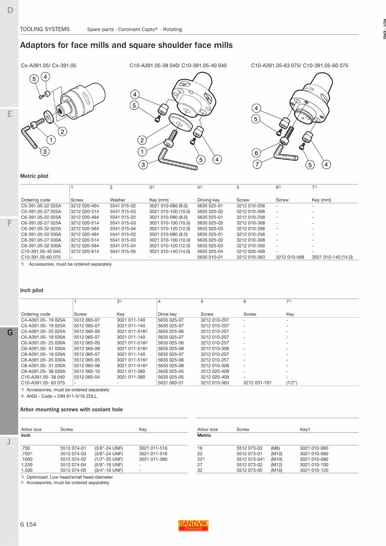
G 154
TOOLING SYSTEMS Spare parts - Coromant Capto® - Rotating
E
F
G
J
D
G
RO
T - E
NG
TOOLING SYSTEMS Spare parts − Coromant Capto® − Rotating
Adaptors for face mills and square shoulder face mills
Metric pilot
Inch pilot
Arbor mounting screws with coolant hole
Cx-A391.05/ Cx-391.05 C10-A391.05-38 040/ C10-391.05-40 040 C10-A391.05-63 075/ C10-391.05-60 075
1 2 31) 41) 5 61) 71)
Ordering code Screw Washer Key (mm) Driving key Screw Screw Key (mm)C5-391.05-22 025A 3212 020-464 5541 015-02 3021 010-080 (8.0) 5635 025-01 3212 010-258 - -C5-391.05-27 025A 3212 020-514 5541 015-03 3021 010-100 (10.0) 5635 025-02 3212 010-308 - -C6-391.05-22 025A 3212 020-464 5541 015-02 3021 010-080 (8.0) 5635 025-01 3212 010-258 - -C6-391.05-27 025A 3212 020-514 5541 015-03 3021 010-100 (10.0) 5635 025-02 3212 010-308 - -C6-391.05-32 025A 3212 020-564 5541 015-04 3021 010-120 (12.0) 5635 025-03 3212 010-358 - -C8-391.05-22 030A 3212 020-464 5541 015-02 3021 010-080 (8.0) 5635 025-01 3212 010-258 - -C8-391.05-27 030A 3212 020-514 5541 015-03 3021 010-100 (10.0) 5635 025-02 3212 010-308 - -C8-391.05-32 030A 3212 020-564 5541 015-04 3021 010-120 (12.0) 5635 025-03 3212 010-358 - -C10-391.05-40 040 3212 020-614 5541 015-05 3021 010-140 (14.0) 5635 025-04 3212 020-409 - -C10-391.05-60 075 - - - 5635 010-01 3212 010-363 3212 010-568 3021 010-140 (14.0)1) Accessories, must be ordered separately
1 31) 4 5 6 71)
Ordering code Screw Key Drive key Screw Screw KeyC4-A391.05- 19 025A 5512 065-07 3021 011-140 5635 025-07 3212 010-207 - -C5-A391.05- 19 025A 5512 065-07 3021 011-140 5635 025-07 3212 010-207 - -C5-A391.05- 25 025A 5512 065-05 3021 011-5162) 5635 025-06 3212 010-257 - -C6-A391.05- 19 030A 5512 065-07 3021 011-140 5635 025-07 3212 010-207 - -C6-A391.05- 25 030A 5512 065-05 3021 011-5162) 5635 025-06 3212 010-257 - -C6-A391.05- 31 030A 5512 065-06 3021 011-5162) 5635 025-08 3212 010-308 - -C8-A391.05- 19 030A 5512 065-07 3021 011-140 5635 025-07 3212 010-207 - -C8-A391.05- 25 030A 5512 065-05 3021 011-5162) 5635 025-06 3212 010-257 - -C8-A391.05- 31 030A 5512 065-06 3021 011-5162) 5635 025-08 3212 010-308 - -C8-A391.05- 38 030A 5512 065-10 3021 011-380 5635 025-05 3212 020-409 - -C10-A391.05- 38 040 5512 065-04 3021 011-380 5635 025-05 3212 020-409 - -C10-A391.05- 63 075 - - 5631 060-01 3212 010-363 3212 031-761 (1/2")1) Accessories, must be ordered separately 2) ANSI - Code = DIN 911-5/16 ZDLL
Arbor size Screw Key Arbor size Screw Key2)
Inch Metric
.750 5512 074-01 (3/8"-24 UNF) 3021 011-516 16 5512 073-03 (M8) 3021 010-060
.7501) 5512 074-03 (3/8"-24 UNF) 3021 011-516 22 5512 073-01 (M10) 3021 010-080
.1000 5512 074-02 (1/2"-20 UNF) 3021 011-380 221) 5512 073-041) (M10) 3021 010-0801.250 5512 074-04 (5/8"-18 UNF) - 27 5512 073-02 (M12) 3021 010-1001.500 5512 074-05 (3/4"-16 UNF) - 32 5512 073-05 (M16) 3021 010-1201) Optimized: Low head/small head-diameter2) Accessories, must be ordered separately
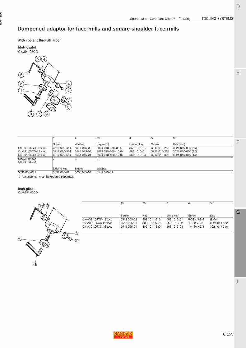
E
G 155
F
G
J
D
G
Spare parts - Coromant Capto® - Rotating TOOLING SYSTEMS
RO
T -
EN
G
TOOLING SYSTEMS Spare parts − Coromant Capto® − Rotating
Dampened adaptor for face mills and square shoulder face mills
With coolant through arbor
Metric pilotCx.391.05CD
1 2 31) 4 5 61)
Screw Washer Key (mm) Driving key Screw Key (mm)Cx-391.05CD-22 xxx 3212 020-464 5541 015-02 3021 010-080 (8.0) 5631 012-01 3212 010-258 3021 010-030 (3.0)Cx-391.05CD-27 xxx 3212 020-514 5541 015-03 3021 010-100 (10.0) 5631 010-01 3212 010-258 3021 010-030 (3.0)Cx-391.05CD-32 xxx 3212 020-564 5541 015-04 3021 010-120 (12.0) 5631 010-04 3212 010-308 3021 010-040 (4.0)Sleeve set forCx-391.05CD
7 8 9
Driving key Sleeve Washer5638 035-011 5631 016-01 5638 035-01 5541 015-091) Accessories, must be ordered separately
Inch pilotCx-A391.05CD
11) 21) 3 4 51)
Screw Key Drive key Screw KeyCx-A391.05CD-19 xxx 5512 065-02 3021 011-316 5631 013-01 8-32 x 3/8M (9/64)Cx-A391.05CD-25 xxx 5512 065-08 3021 011 532 5631 013-02 10-32 x 3/8 3021 011 532Cx-A391.05CD-38 xxx 5512 065-04 3021 011-380 5631 013-04 1/4-20 x 3/4 3021 011 316
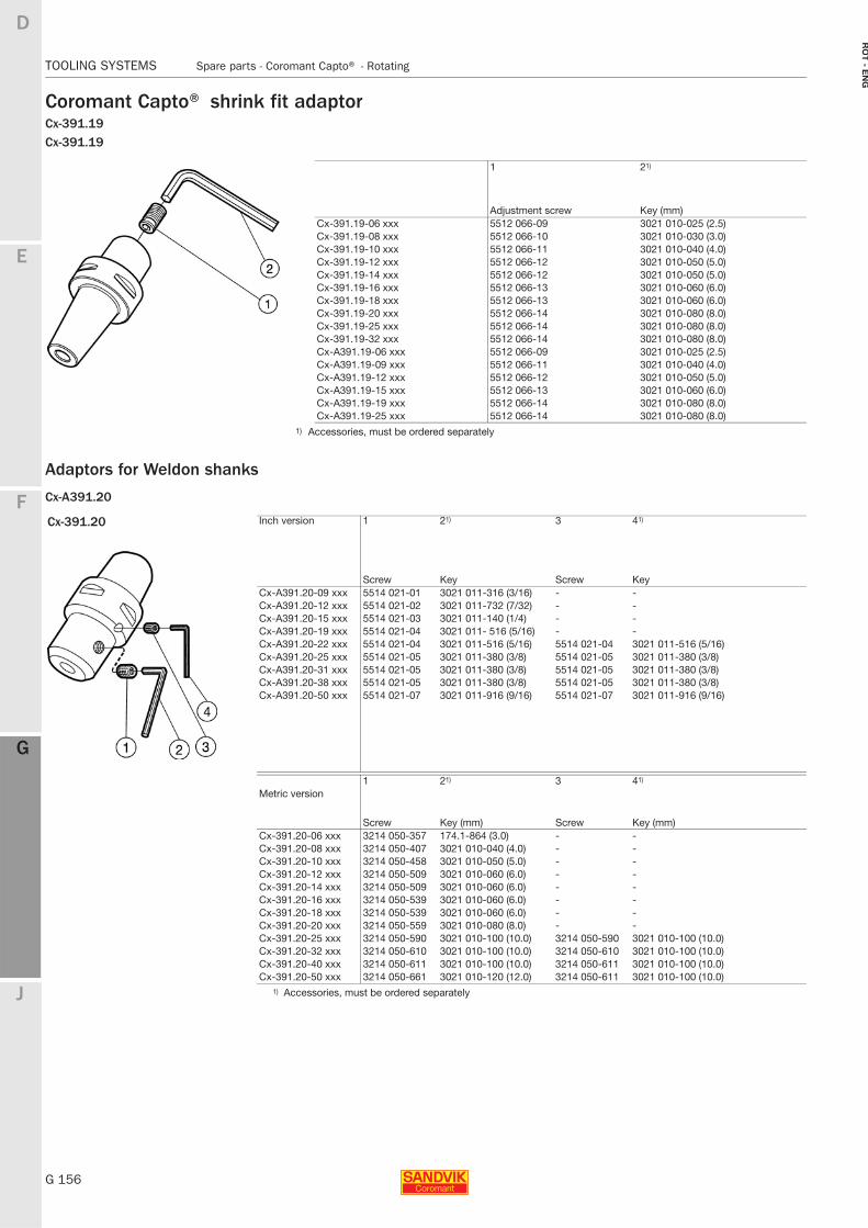
G 156
TOOLING SYSTEMS Spare parts - Coromant Capto® - Rotating
E
F
G
J
D
G
RO
T - E
NG
TOOLING SYSTEMS Spare parts − Coromant Capto® − Rotating
Coromant Capto® shrink fit adaptorCx-391.19Cx-391.19
Adaptors for Weldon shanks
Cx-A391.20
1 21)
Adjustment screw Key (mm)Cx-391.19-06 xxx 5512 066-09 3021 010-025 (2.5)Cx-391.19-08 xxx 5512 066-10 3021 010-030 (3.0)Cx-391.19-10 xxx 5512 066-11 3021 010-040 (4.0)Cx-391.19-12 xxx 5512 066-12 3021 010-050 (5.0)Cx-391.19-14 xxx 5512 066-12 3021 010-050 (5.0)Cx-391.19-16 xxx 5512 066-13 3021 010-060 (6.0)Cx-391.19-18 xxx 5512 066-13 3021 010-060 (6.0)Cx-391.19-20 xxx 5512 066-14 3021 010-080 (8.0)Cx-391.19-25 xxx 5512 066-14 3021 010-080 (8.0)Cx-391.19-32 xxx 5512 066-14 3021 010-080 (8.0)Cx-A391.19-06 xxx 5512 066-09 3021 010-025 (2.5)Cx-A391.19-09 xxx 5512 066-11 3021 010-040 (4.0)Cx-A391.19-12 xxx 5512 066-12 3021 010-050 (5.0)Cx-A391.19-15 xxx 5512 066-13 3021 010-060 (6.0)Cx-A391.19-19 xxx 5512 066-14 3021 010-080 (8.0)Cx-A391.19-25 xxx 5512 066-14 3021 010-080 (8.0)
1) Accessories, must be ordered separately
Cx-391.20 Inch version 1 21) 3 41)
Screw Key Screw Key Cx-A391.20-09 xxx 5514 021-01 3021 011-316 (3/16) - -Cx-A391.20-12 xxx 5514 021-02 3021 011-732 (7/32) - -Cx-A391.20-15 xxx 5514 021-03 3021 011-140 (1/4) - -Cx-A391.20-19 xxx 5514 021-04 3021 011- 516 (5/16) - -Cx-A391.20-22 xxx 5514 021-04 3021 011-516 (5/16) 5514 021-04 3021 011-516 (5/16)Cx-A391.20-25 xxx 5514 021-05 3021 011-380 (3/8) 5514 021-05 3021 011-380 (3/8)Cx-A391.20-31 xxx 5514 021-05 3021 011-380 (3/8) 5514 021-05 3021 011-380 (3/8)Cx-A391.20-38 xxx 5514 021-05 3021 011-380 (3/8) 5514 021-05 3021 011-380 (3/8)Cx-A391.20-50 xxx 5514 021-07 3021 011-916 (9/16) 5514 021-07 3021 011-916 (9/16)
Metric version1 21) 3 41)
Screw Key (mm) Screw Key (mm)Cx-391.20-06 xxx 3214 050-357 174.1-864 (3.0) - -Cx-391.20-08 xxx 3214 050-407 3021 010-040 (4.0) - -Cx-391.20-10 xxx 3214 050-458 3021 010-050 (5.0) - -Cx-391.20-12 xxx 3214 050-509 3021 010-060 (6.0) - -Cx-391.20-14 xxx 3214 050-509 3021 010-060 (6.0) - -Cx-391.20-16 xxx 3214 050-539 3021 010-060 (6.0) - -Cx-391.20-18 xxx 3214 050-539 3021 010-060 (6.0) - -Cx-391.20-20 xxx 3214 050-559 3021 010-080 (8.0) - -Cx-391.20-25 xxx 3214 050-590 3021 010-100 (10.0) 3214 050-590 3021 010-100 (10.0)Cx-391.20-32 xxx 3214 050-610 3021 010-100 (10.0) 3214 050-610 3021 010-100 (10.0)Cx-391.20-40 xxx 3214 050-611 3021 010-100 (10.0) 3214 050-611 3021 010-100 (10.0)Cx-391.20-50 xxx 3214 050-661 3021 010-120 (12.0) 3214 050-611 3021 010-100 (10.0)
1) Accessories, must be ordered separately
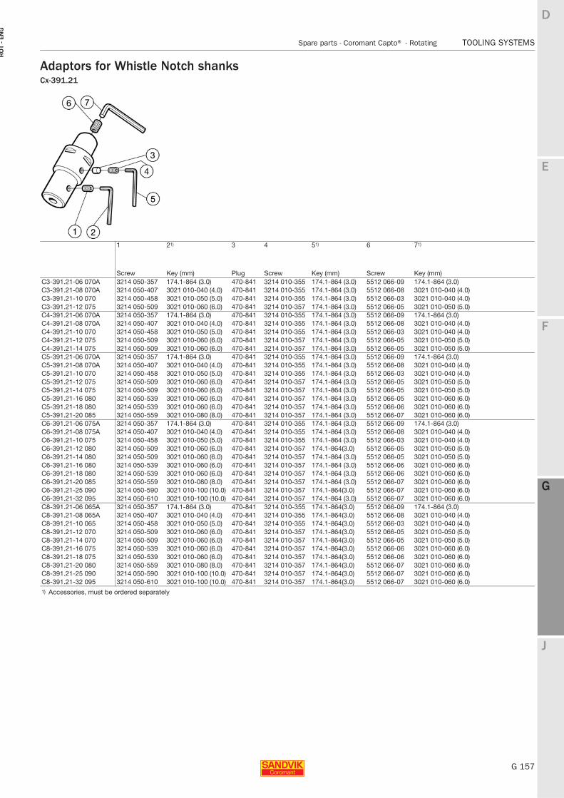
E
G 157
F
G
J
D
G
Spare parts - Coromant Capto® - Rotating TOOLING SYSTEMS
RO
T -
EN
G
TOOLING SYSTEMS Spare parts − Coromant Capto® − Rotating
Adaptors for Whistle Notch shanksCx-391.21
1 21) 3 4 51) 6 71)
Screw Key (mm) Plug Screw Key (mm) Screw Key (mm)C3-391.21-06 070A 3214 050-357 174.1-864 (3.0) 470-841 3214 010-355 174.1-864 (3.0) 5512 066-09 174.1-864 (3.0)C3-391.21-08 070A 3214 050-407 3021 010-040 (4.0) 470-841 3214 010-355 174.1-864 (3.0) 5512 066-08 3021 010-040 (4.0)C3-391.21-10 070 3214 050-458 3021 010-050 (5.0) 470-841 3214 010-355 174.1-864 (3.0) 5512 066-03 3021 010-040 (4.0)C3-391.21-12 075 3214 050-509 3021 010-060 (6.0) 470-841 3214 010-357 174.1-864 (3.0) 5512 066-05 3021 010-050 (5.0)C4-391.21-06 070A 3214 050-357 174.1-864 (3.0) 470-841 3214 010-355 174.1-864 (3.0) 5512 066-09 174.1-864 (3.0)C4-391.21-08 070A 3214 050-407 3021 010-040 (4.0) 470-841 3214 010-355 174.1-864 (3.0) 5512 066-08 3021 010-040 (4.0)C4-391.21-10 070 3214 050-458 3021 010-050 (5.0) 470-841 3214 010-355 174.1-864 (3.0) 5512 066-03 3021 010-040 (4.0)C4-391.21-12 075 3214 050-509 3021 010-060 (6.0) 470-841 3214 010-357 174.1-864 (3.0) 5512 066-05 3021 010-050 (5.0)C4-391.21-14 075 3214 050-509 3021 010-060 (6.0) 470-841 3214 010-357 174.1-864 (3.0) 5512 066-05 3021 010-050 (5.0)C5-391.21-06 070A 3214 050-357 174.1-864 (3.0) 470-841 3214 010-355 174.1-864 (3.0) 5512 066-09 174.1-864 (3.0)C5-391.21-08 070A 3214 050-407 3021 010-040 (4.0) 470-841 3214 010-355 174.1-864 (3.0) 5512 066-08 3021 010-040 (4.0)C5-391.21-10 070 3214 050-458 3021 010-050 (5.0) 470-841 3214 010-355 174.1-864 (3.0) 5512 066-03 3021 010-040 (4.0)C5-391.21-12 075 3214 050-509 3021 010-060 (6.0) 470-841 3214 010-357 174.1-864 (3.0) 5512 066-05 3021 010-050 (5.0)C5-391.21-14 075 3214 050-509 3021 010-060 (6.0) 470-841 3214 010-357 174.1-864 (3.0) 5512 066-05 3021 010-050 (5.0)C5-391.21-16 080 3214 050-539 3021 010-060 (6.0) 470-841 3214 010-357 174.1-864 (3.0) 5512 066-05 3021 010-060 (6.0)C5-391.21-18 080 3214 050-539 3021 010-060 (6.0) 470-841 3214 010-357 174.1-864 (3.0) 5512 066-06 3021 010-060 (6.0)C5-391.21-20 085 3214 050-559 3021 010-080 (8.0) 470-841 3214 010-357 174.1-864 (3.0) 5512 066-07 3021 010-060 (6.0)C6-391.21-06 075A 3214 050-357 174.1-864 (3.0) 470-841 3214 010-355 174.1-864 (3.0) 5512 066-09 174.1-864 (3.0)C6-391.21-08 075A 3214 050-407 3021 010-040 (4.0) 470-841 3214 010-355 174.1-864 (3.0) 5512 066-08 3021 010-040 (4.0)C6-391.21-10 075 3214 050-458 3021 010-050 (5.0) 470-841 3214 010-355 174.1-864 (3.0) 5512 066-03 3021 010-040 (4.0)C6-391.21-12 080 3214 050-509 3021 010-060 (6.0) 470-841 3214 010-357 174.1-864(3.0) 5512 066-05 3021 010-050 (5.0)C6-391.21-14 080 3214 050-509 3021 010-060 (6.0) 470-841 3214 010-357 174.1-864 (3.0) 5512 066-05 3021 010-050 (5.0)C6-391.21-16 080 3214 050-539 3021 010-060 (6.0) 470-841 3214 010-357 174.1-864 (3.0) 5512 066-06 3021 010-060 (6.0)C6-391.21-18 080 3214 050-539 3021 010-060 (6.0) 470-841 3214 010-357 174.1-864 (3.0) 5512 066-06 3021 010-060 (6.0)C6-391.21-20 085 3214 050-559 3021 010-080 (8.0) 470-841 3214 010-357 174.1-864 (3.0) 5512 066-07 3021 010-060 (6.0)C6-391.21-25 090 3214 050-590 3021 010-100 (10.0) 470-841 3214 010-357 174.1-864(3.0) 5512 066-07 3021 010-060 (6.0)C6-391.21-32 095 3214 050-610 3021 010-100 (10.0) 470-841 3214 010-357 174.1-864 (3.0) 5512 066-07 3021 010-060 (6.0)C8-391.21-06 065A 3214 050-357 174.1-864 (3.0) 470-841 3214 010-355 174.1-864(3.0) 5512 066-09 174.1-864 (3.0)C8-391.21-08 065A 3214 050-407 3021 010-040 (4.0) 470-841 3214 010-355 174.1-864(3.0) 5512 066-08 3021 010-040 (4.0)C8-391.21-10 065 3214 050-458 3021 010-050 (5.0) 470-841 3214 010-355 174.1-864(3.0) 5512 066-03 3021 010-040 (4.0)C8-391.21-12 070 3214 050-509 3021 010-060 (6.0) 470-841 3214 010-357 174.1-864(3.0) 5512 066-05 3021 010-050 (5.0)C8-391.21-14 070 3214 050-509 3021 010-060 (6.0) 470-841 3214 010-357 174.1-864(3.0) 5512 066-05 3021 010-050 (5.0)C8-391.21-16 075 3214 050-539 3021 010-060 (6.0) 470-841 3214 010-357 174.1-864(3.0) 5512 066-06 3021 010-060 (6.0)C8-391.21-18 075 3214 050-539 3021 010-060 (6.0) 470-841 3214 010-357 174.1-864(3.0) 5512 066-06 3021 010-060 (6.0)C8-391.21-20 080 3214 050-559 3021 010-080 (8.0) 470-841 3214 010-357 174.1-864(3.0) 5512 066-07 3021 010-060 (6.0)C8-391.21-25 090 3214 050-590 3021 010-100 (10.0) 470-841 3214 010-357 174.1-864(3.0) 5512 066-07 3021 010-060 (6.0)C8-391.21-32 095 3214 050-610 3021 010-100 (10.0) 470-841 3214 010-357 174.1-864(3.0) 5512 066-07 3021 010-060 (6.0)1) Accessories, must be ordered separately
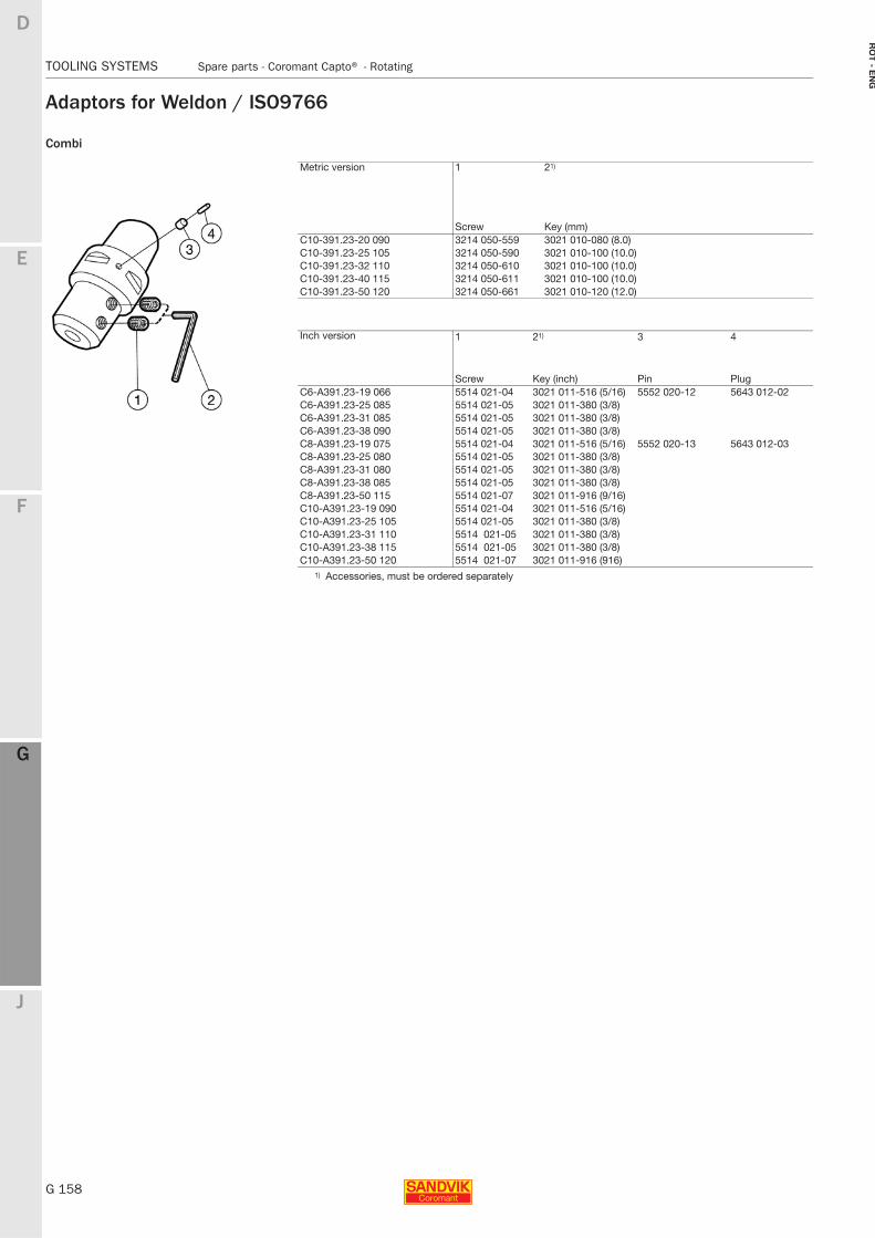
G 158
TOOLING SYSTEMS Spare parts - Coromant Capto® - Rotating
E
F
G
J
D
G
RO
T - E
NG
TOOLING SYSTEMS Spare parts − Coromant Capto® − Rotating
Adaptors for Weldon / ISO9766
Combi
Metric version 1 21)
Screw Key (mm)C10-391.23-20 090 3214 050-559 3021 010-080 (8.0)C10-391.23-25 105 3214 050-590 3021 010-100 (10.0)C10-391.23-32 110 3214 050-610 3021 010-100 (10.0)C10-391.23-40 115 3214 050-611 3021 010-100 (10.0)C10-391.23-50 120 3214 050-661 3021 010-120 (12.0)
Inch version 1 21) 3 4
Screw Key (inch) Pin PlugC6-A391.23-19 066 5514 021-04 3021 011-516 (5/16) 5552 020-12 5643 012-02C6-A391.23-25 085 5514 021-05 3021 011-380 (3/8)C6-A391.23-31 085 5514 021-05 3021 011-380 (3/8)C6-A391.23-38 090 5514 021-05 3021 011-380 (3/8)C8-A391.23-19 075 5514 021-04 3021 011-516 (5/16) 5552 020-13 5643 012-03C8-A391.23-25 080 5514 021-05 3021 011-380 (3/8)C8-A391.23-31 080 5514 021-05 3021 011-380 (3/8)C8-A391.23-38 085 5514 021-05 3021 011-380 (3/8)C8-A391.23-50 115 5514 021-07 3021 011-916 (9/16)C10-A391.23-19 090 5514 021-04 3021 011-516 (5/16)C10-A391.23-25 105 5514 021-05 3021 011-380 (3/8)C10-A391.23-31 110 5514 021-05 3021 011-380 (3/8)C10-A391.23-38 115 5514 021-05 3021 011-380 (3/8)C10-A391.23-50 120 5514 021-07 3021 011-916 (916)
1) Accessories, must be ordered separately
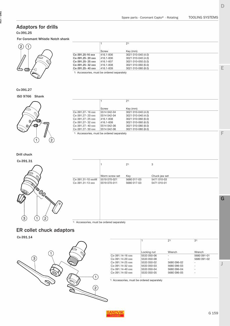
E
G 159
F
G
J
D
G
Spare parts - Coromant Capto® - Rotating TOOLING SYSTEMS
RO
T -
EN
G
TOOLING SYSTEMS Spare parts − Coromant Capto® − Rotating
Adaptors for drillsCx-391.25
Cx-391.27
Drill chuck
ER collet chuck adaptors
For Coromant Whistle Notch shank1 21)
Screw Key (mm)Cx-391.25-16 xxx 416.1-836 3021 010-040 (4.0)Cx-391.25- 20 xxx 416.1-836 3021 010-040 (4.0)Cx-391.25- 25 xxx 416.1-837 3021 010-050 (5.0)Cx-391.25- 32 xxx 416.1-838 3021 010-060 (6.0)Cx-391.25- 40 xxx 416.1-839 3021 010-080 (8.0)1) Accessories, must be ordered separately
ISO 9766 Shank1 21)
Screw Key (mm)Cx-391.27- 16 xxx 5514 042-04 3021 010-040 (4.0)Cx-391.27- 20 xxx 5514 042-04 3021 010-040 (4.0)Cx-391.27- 25 xxx 416.1-838 3021 010-060 (6.0)Cx-391.27- 32 xxx 416.1-838 3021 010-060 (6.0)Cx-391.27- 40 xxx 5514 042-06 3021 010-080 (8.0)Cx-391.27- 50 xxx 5514 042-06 3021 010-080 (8.0)1) Accessories, must be ordered separately
Cx-391.31 1 21) 3
Worm screw set Key Chuck jaw setCx-391.31-10 xxxM 5519 070-021 5680 017-03 5471 010-03Cx-391.31-13 xxx 5519 070-011 5680 017-03 5471 010-01
1) Accessories, must be ordered separately
Cx-391.141 21) 31)
Locking nut Wrench WrenchCx-391.14-16 xxx 5533 050-06 - 5680 091-01Cx-391.14-20 xxx 5533 050-08 - 5680 091-02Cx-391.14-25 xxx 5533 050-02 5680 096-02 -Cx-391.14-32 xxx 5533 050-03 5680 096-03 -Cx-391.14-40 xxx 5533 050-04 5680 096-04 -Cx-391.14-50 xxx 5533 050-05 5680 096-05 -
1) Accessories, must be ordered separately
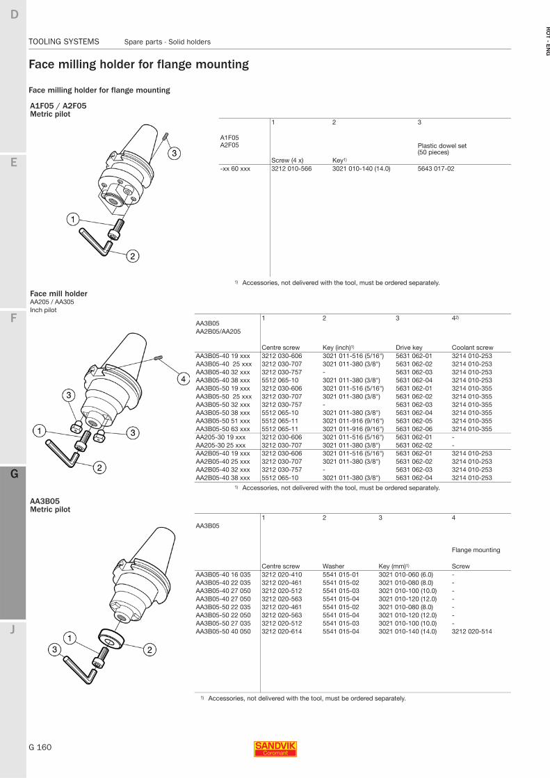
G 160
TOOLING SYSTEMS Spare parts - Solid holders
E
F
G
J
D
G
RO
T - E
NG
TOOLING SYSTEMS Spare parts - Solid holders
Face milling holder for flange mounting
Face milling holder for flange mounting
A1F05 / A2F05Metric pilot
1 2 3
A1F05Plastic dowel set (50 pieces)
A2F05
Screw (4 x) Key1)
-xx 60 xxx 3212 010-566 3021 010-140 (14.0) 5643 017-02
1) Accessories, not delivered with the tool, must be ordered separately.
Face mill holderAA205 / AA305Inch pilot
1 2 3 42)AA3B05AA2B05/AA205
Centre screw Key (inch)1) Drive key Coolant screwAA3B05-40 19 xxx 3212 030-606 3021 011-516 (5/16") 5631 062-01 3214 010-253AA3B05-40 25 xxx 3212 030-707 3021 011-380 (3/8") 5631 062-02 3214 010-253AA3B05-40 32 xxx 3212 030-757 - 5631 062-03 3214 010-253AA3B05-40 38 xxx 5512 065-10 3021 011-380 (3/8") 5631 062-04 3214 010-253AA3B05-50 19 xxx 3212 030-606 3021 011-516 (5/16") 5631 062-01 3214 010-355AA3B05-50 25 xxx 3212 030-707 3021 011-380 (3/8") 5631 062-02 3214 010-355AA3B05-50 32 xxx 3212 030-757 - 5631 062-03 3214 010-355AA3B05-50 38 xxx 5512 065-10 3021 011-380 (3/8") 5631 062-04 3214 010-355AA3B05-50 51 xxx 5512 065-11 3021 011-916 (9/16") 5631 062-05 3214 010-355AA3B05-50 63 xxx 5512 065-11 3021 011-916 (9/16") 5631 062-06 3214 010-355AA205-30 19 xxx 3212 030-606 3021 011-516 (5/16") 5631 062-01 -AA205-30 25 xxx 3212 030-707 3021 011-380 (3/8") 5631 062-02 -AA2B05-40 19 xxx 3212 030-606 3021 011-516 (5/16") 5631 062-01 3214 010-253AA2B05-40 25 xxx 3212 030-707 3021 011-380 (3/8") 5631 062-02 3214 010-253AA2B05-40 32 xxx 3212 030-757 - 5631 062-03 3214 010-253AA2B05-40 38 xxx 5512 065-10 3021 011-380 (3/8") 5631 062-04 3214 010-253
1) Accessories, not delivered with the tool, must be ordered separately.
AA3B05Metric pilot
1 2 3 4AA3B05
Flange mounting
Centre screw Washer Key (mm)1) ScrewAA3B05-40 16 035 3212 020-410 5541 015-01 3021 010-060 (6.0) -AA3B05-40 22 035 3212 020-461 5541 015-02 3021 010-080 (8.0) -AA3B05-40 27 050 3212 020-512 5541 015-03 3021 010-100 (10.0) -AA3B05-40 27 050 3212 020-563 5541 015-04 3021 010-120 (12.0) -AA3B05-50 22 035 3212 020-461 5541 015-02 3021 010-080 (8.0) -AA3B05-50 22 050 3212 020-563 5541 015-04 3021 010-120 (12.0) -AA3B05-50 27 035 3212 020-512 5541 015-03 3021 010-100 (10.0) -AA3B05-50 40 050 3212 020-614 5541 015-04 3021 010-140 (14.0) 3212 020-514
1) Accessories, not delivered with the tool, must be ordered separately.
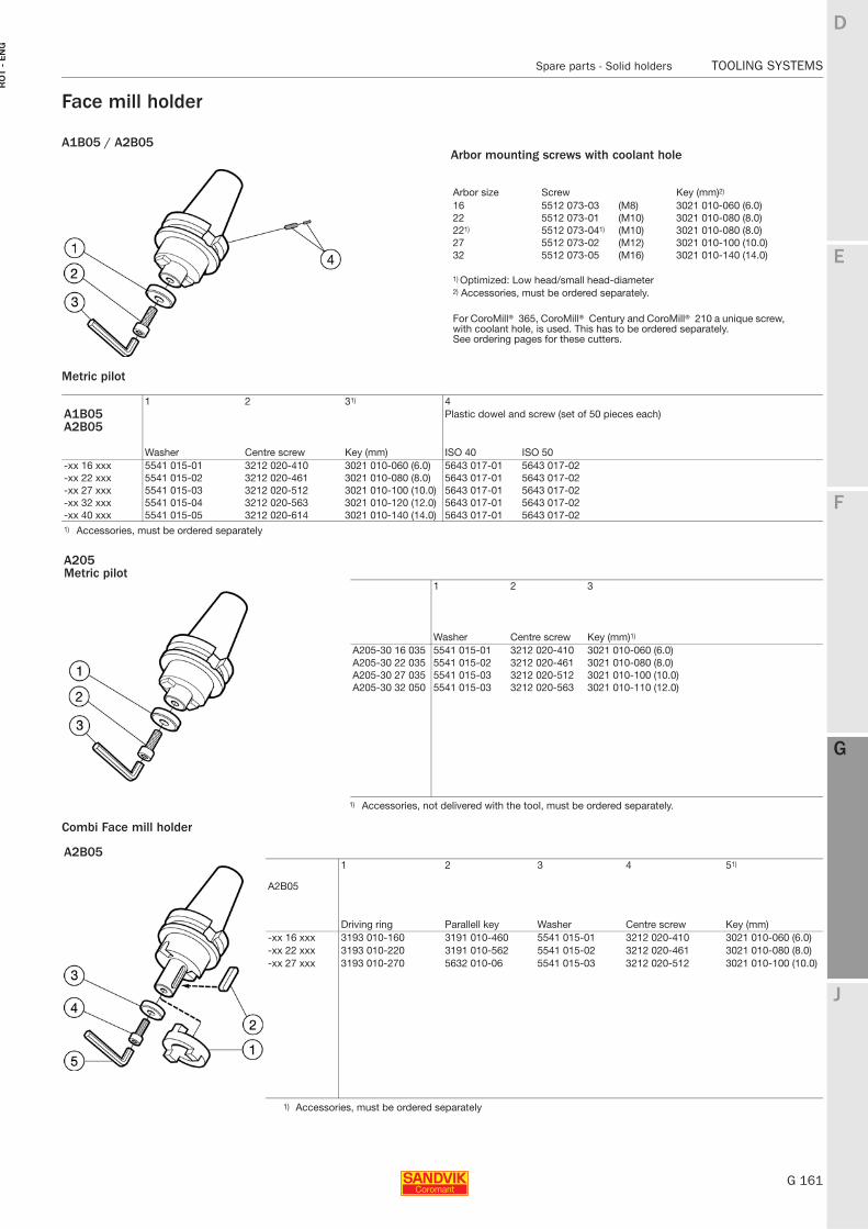
E
G 161
F
G
J
D
G
Spare parts - Solid holders TOOLING SYSTEMS
RO
T -
EN
G
TOOLING SYSTEMS Spare parts - Solid holders
Face mill holder
A1B05 / A2B05
Metric pilot
Combi Face mill holder
1 2 31) 4A1B05 Plastic dowel and screw (set of 50 pieces each)A2B05
Washer Centre screw Key (mm) ISO 40 ISO 50-xx 16 xxx 5541 015-01 3212 020-410 3021 010-060 (6.0) 5643 017-01 5643 017-02-xx 22 xxx 5541 015-02 3212 020-461 3021 010-080 (8.0) 5643 017-01 5643 017-02-xx 27 xxx 5541 015-03 3212 020-512 3021 010-100 (10.0) 5643 017-01 5643 017-02-xx 32 xxx 5541 015-04 3212 020-563 3021 010-120 (12.0) 5643 017-01 5643 017-02-xx 40 xxx 5541 015-05 3212 020-614 3021 010-140 (14.0) 5643 017-01 5643 017-021) Accessories, must be ordered separately
A205Metric pilot
1 2 3
Washer Centre screw Key (mm)1)
A205-30 16 035 5541 015-01 3212 020-410 3021 010-060 (6.0)A205-30 22 035 5541 015-02 3212 020-461 3021 010-080 (8.0)A205-30 27 035 5541 015-03 3212 020-512 3021 010-100 (10.0)A205-30 32 050 5541 015-03 3212 020-563 3021 010-110 (12.0)
1) Accessories, not delivered with the tool, must be ordered separately.
A2B051 2 3 4 51)
A2B05
Driving ring Parallell key Washer Centre screw Key (mm)-xx 16 xxx 3193 010-160 3191 010-460 5541 015-01 3212 020-410 3021 010-060 (6.0)-xx 22 xxx 3193 010-220 3191 010-562 5541 015-02 3212 020-461 3021 010-080 (8.0)-xx 27 xxx 3193 010-270 5632 010-06 5541 015-03 3212 020-512 3021 010-100 (10.0)
1) Accessories, must be ordered separately
Arbor mounting screws with coolant hole
Arbor size Screw Key (mm)2)
16 5512 073-03 (M8) 3021 010-060 (6.0)22 5512 073-01 (M10) 3021 010-080 (8.0)221) 5512 073-041) (M10) 3021 010-080 (8.0)27 5512 073-02 (M12) 3021 010-100 (10.0)32 5512 073-05 (M16) 3021 010-140 (14.0)
1) Optimized: Low head/small head-diameter2) Accessories, must be ordered separately.
For CoroMill® 365, CoroMill® Century and CoroMill® 210 a unique screw, with coolant hole, is used. This has to be ordered separately.See ordering pages for these cutters.
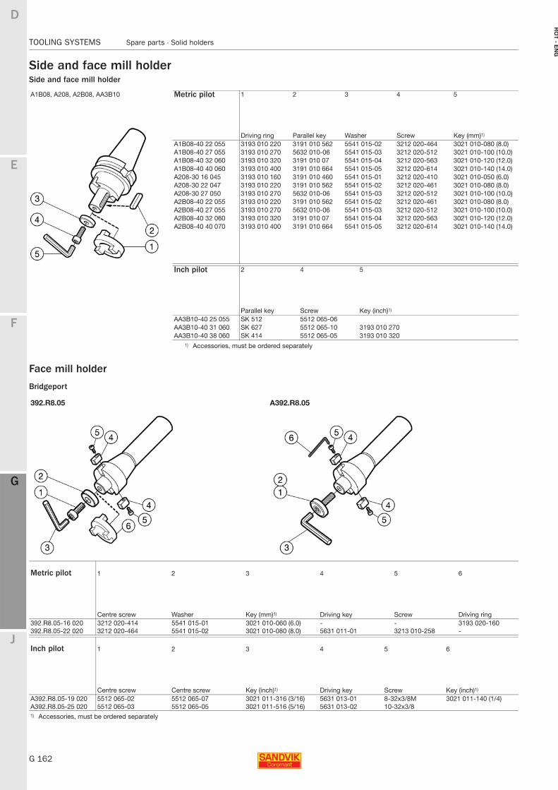
G 162
TOOLING SYSTEMS Spare parts - Solid holders
E
F
G
J
D
G
RO
T - E
NG
TOOLING SYSTEMS Spare parts - Solid holders
Side and face mill holderSide and face mill holder
Face mill holder
Bridgeport
A1B08, A208, A2B08, AA3B10 Metric pilot 1 2 3 4 5
Driving ring Parallel key Washer Screw Key (mm)1)
A1B08-40 22 055 3193 010 220 3191 010 562 5541 015-02 3212 020-464 3021 010-080 (8.0)A1B08-40 27 055 3193 010 270 5632 010-06 5541 015-03 3212 020-512 3021 010-100 (10.0)A1B08-40 32 060 3193 010 320 3191 010 07 5541 015-04 3212 020-563 3021 010-120 (12.0)A1B08-40 40 060 3193 010 400 3191 010 664 5541 015-05 3212 020-614 3021 010-140 (14.0)A208-30 16 045 3193 010 160 3191 010 460 5541 015-01 3212 020-410 3021 010-050 (6.0)A208-30 22 047 3193 010 220 3191 010 562 5541 015-02 3212 020-461 3021 010-080 (8.0)A208-30 27 050 3193 010 270 5632 010-06 5541 015-03 3212 020-512 3021 010-100 (10.0)A2B08-40 22 055 3193 010 220 3191 010 562 5541 015-02 3212 020-461 3021 010-080 (8.0)A2B08-40 27 055 3193 010 270 5632 010-06 5541 015-03 3212 020-512 3021 010-100 (10.0)A2B08-40 32 060 3193 010 320 3191 010 07 5541 015-04 3212 020-563 3021 010-120 (12.0)A2B08-40 40 070 3193 010 400 3191 010 664 5541 015-05 3212 020-614 3021 010-140 (14.0)
Inch pilot 2 4 5
Parallel key Screw Key (inch)1)
AA3B10-40 25 055 SK 512 5512 065-06AA3B10-40 31 060 SK 627 5512 065-10 3193 010 270AA3B10-40 38 060 SK 414 5512 065-05 3193 010 320
1) Accessories, must be ordered separately
392.R8.05 A392.R8.05
Metric pilot 1 2 3 4 5 6
Centre screw Washer Key (mm)1) Driving key Screw Driving ring392.R8.05-16 020 3212 020-414 5541 015-01 3021 010-060 (6.0) - - 3193 020-160392.R8.05-22 020 3212 020-464 5541 015-02 3021 010-080 (8.0) 5631 011-01 3213 010-258 -
Inch pilot 1 2 3 4 5 6
Centre screw Centre screw Key (inch)1) Driving key Screw Key (inch)1)
A392.R8.05-19 020 5512 065-02 5512 065-07 3021 011-316 (3/16) 5631 013-01 8-32x3/8M 3021 011-140 (1/4)A392.R8.05-25 020 5512 065-03 5512 065-05 3021 011-516 (5/16) 5631 013-02 10-32x3/81) Accessories, must be ordered separately
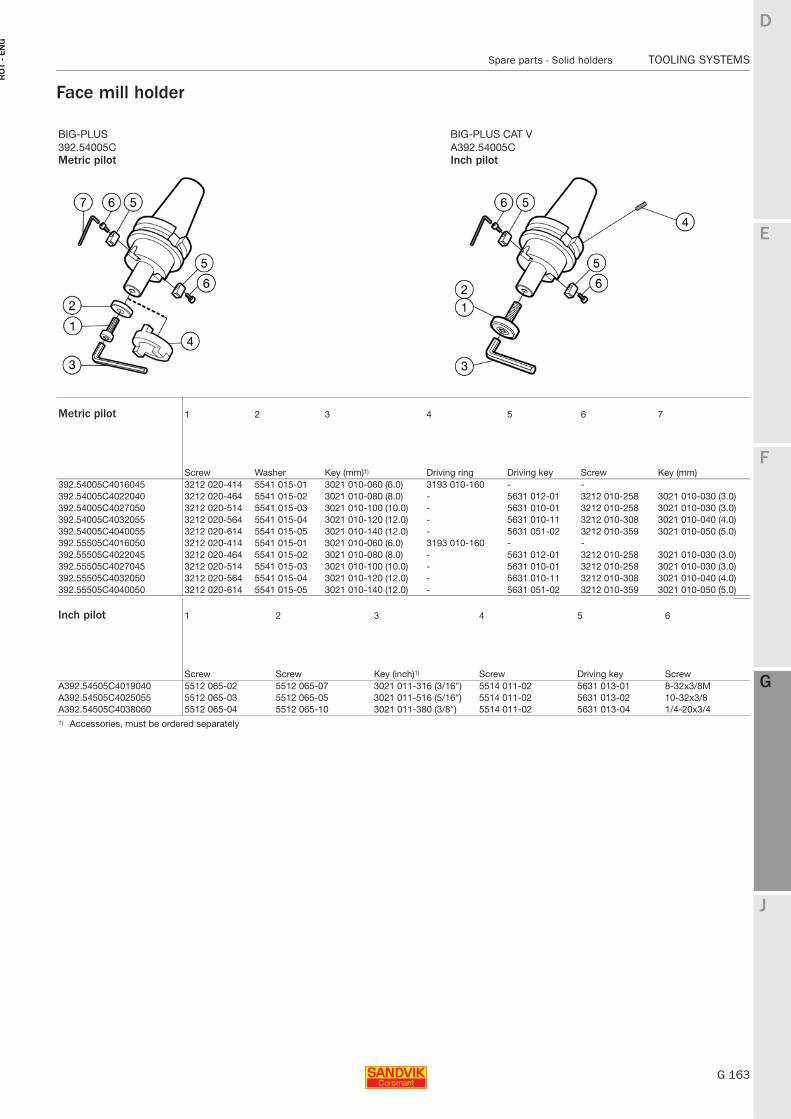
E
G 163
F
G
J
D
G
Spare parts - Solid holders TOOLING SYSTEMS
RO
T -
EN
G
TOOLING SYSTEMS Spare parts - Solid holders
Face mill holder
BIG-PLUS BIG-PLUS CAT V392.54005C A392.54005CMetric pilot Inch pilot
Metric pilot 1 2 3 4 5 6 7
Screw Washer Key (mm)1) Driving ring Driving key Screw Key (mm)392.54005C4016045 3212 020-414 5541 015-01 3021 010-060 (6.0) 3193 010-160 - -392.54005C4022040 3212 020-464 5541 015-02 3021 010-080 (8.0) - 5631 012-01 3212 010-258 3021 010-030 (3.0)392.54005C4027050 3212 020-514 5541 015-03 3021 010-100 (10.0) - 5631 010-01 3212 010-258 3021 010-030 (3.0)392.54005C4032055 3212 020-564 5541 015-04 3021 010-120 (12.0) - 5631 010-11 3212 010-308 3021 010-040 (4.0)392.54005C4040055 3212 020-614 5541 015-05 3021 010-140 (12.0) - 5631 051-02 3212 010-359 3021 010-050 (5.0)392.55505C4016050 3212 020-414 5541 015-01 3021 010-060 (6.0) 3193 010-160 - -392.55505C4022045 3212 020-464 5541 015-02 3021 010-080 (8.0) - 5631 012-01 3212 010-258 3021 010-030 (3.0)392.55505C4027045 3212 020-514 5541 015-03 3021 010-100 (10.0) - 5631 010-01 3212 010-258 3021 010-030 (3.0)392.55505C4032050 3212 020-564 5541 015-04 3021 010-120 (12.0) - 5631 010-11 3212 010-308 3021 010-040 (4.0)392.55505C4040050 3212 020-614 5541 015-05 3021 010-140 (12.0) - 5631 051-02 3212 010-359 3021 010-050 (5.0)
Inch pilot 1 2 3 4 5 6
Screw Screw Key (inch)1) Screw Driving key ScrewA392.54505C4019040 5512 065-02 5512 065-07 3021 011-316 (3/16") 5514 011-02 5631 013-01 8-32x3/8MA392.54505C4025055 5512 065-03 5512 065-05 3021 011-516 (5/16") 5514 011-02 5631 013-02 10-32x3/8A392.54505C4038060 5512 065-04 5512 065-10 3021 011-380 (3/8") 5514 011-02 5631 013-04 1/4-20x3/41) Accessories, must be ordered separately
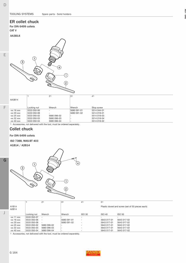
G 164
TOOLING SYSTEMS Spare parts - Solid holders
E
F
G
J
D
G
RO
T - E
NG
TOOLING SYSTEMS Spare parts - Solid holders
ER collet chuckFor DIN 6499 colletsCAT V
Collet chuckFor DIN 6499 collets
AA3B14
1 21) 31) 41)
AA3B14
Locking nut Wrench Wrench Stop screw-xx 16 xxx 5533 050-06 - 5680 091-01 5514 044-01-xx 20 xxx 5533 050-08 - 5680 091-02 5514 018-01-xx 25 xxx 5533 050-02 5680 096-02 - 5514 018-03-xx 32 xxx 5533 050-03 5680 096-03 - 5514 018-04-xx 40 xxx 5533 050-04 5680 096-04 - 5514 018-021) Accessories, not delivered with the tool, must be ordered separately.
ISO 7388, MAS-BT 403
A1B14 / A2B14
1 21) 31) 41) 51)
A1B14 Plastic dowel and screw (set of 50 pieces each)A2B14
Locking nut Wrench Wrench ISO 30 ISO 40 ISO 50-xx 11 xxx 5533 050-07 - - - - --xx 16 xxx 5533 050-06 - 5680 091-01 - 5643 017-01 5643 017-02-xx 20 xxx 5533 050-08 - 5680 091-02 - 5643 017-01 5643 017-02-xx 25 xxx 5533 050-02 5680 096-02 - - 5643 017-01 5643 017-02-xx 32 xxx 5533 050-03 5680 096-03 - - 5643 017-01 5643 017-02-xx 40 xxx 5533 050-04 5680 096-04 - - 5643 017-01 5643 017-021) Accessories, not delivered with the tool, must be ordered separately.
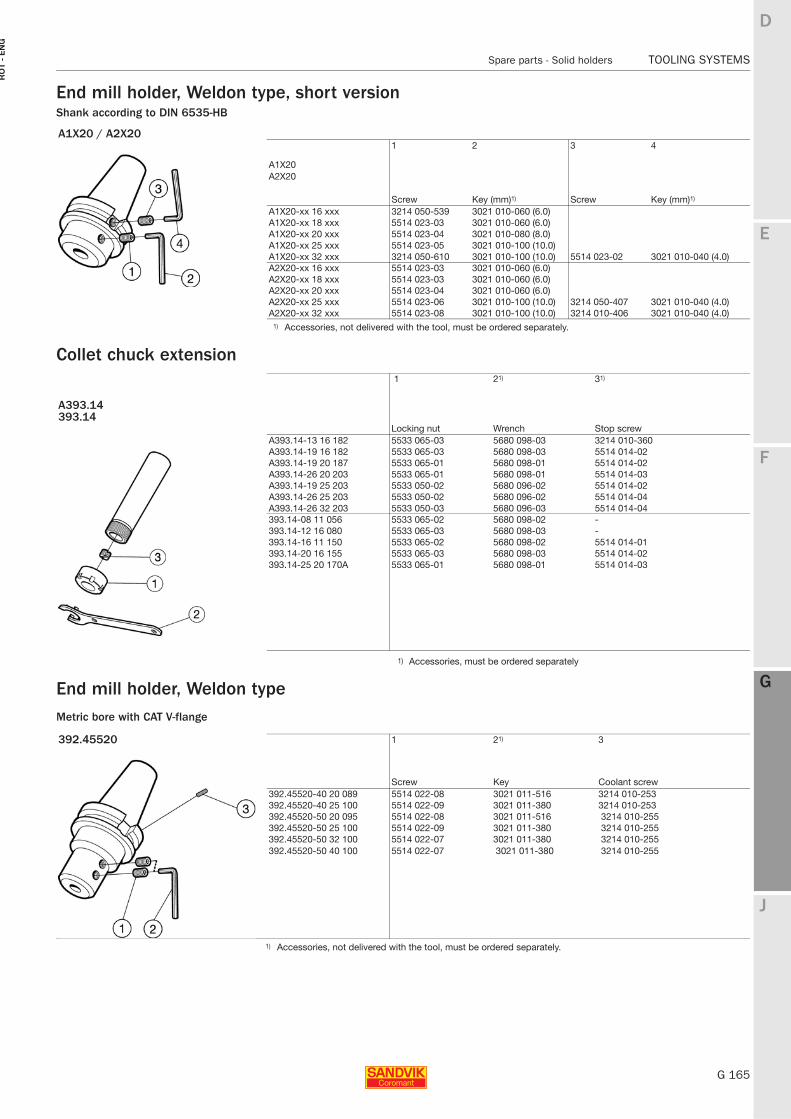
E
G 165
F
G
J
D
G
Spare parts - Solid holders TOOLING SYSTEMS
RO
T -
EN
G
TOOLING SYSTEMS Spare parts - Solid holders
End mill holder, Weldon type, short versionShank according to DIN 6535-HB
Collet chuck extension
End mill holder, Weldon typeMetric bore with CAT V-flange
A1X20 / A2X201 2 3 4
A1X20A2X20
Screw Key (mm)1) Screw Key (mm)1)
A1X20-xx 16 xxx 3214 050-539 3021 010-060 (6.0)A1X20-xx 18 xxx 5514 023-03 3021 010-060 (6.0)A1X20-xx 20 xxx 5514 023-04 3021 010-080 (8.0)A1X20-xx 25 xxx 5514 023-05 3021 010-100 (10.0)A1X20-xx 32 xxx 3214 050-610 3021 010-100 (10.0) 5514 023-02 3021 010-040 (4.0)A2X20-xx 16 xxx 5514 023-03 3021 010-060 (6.0)A2X20-xx 18 xxx 5514 023-03 3021 010-060 (6.0)A2X20-xx 20 xxx 5514 023-04 3021 010-060 (6.0)A2X20-xx 25 xxx 5514 023-06 3021 010-100 (10.0) 3214 050-407 3021 010-040 (4.0)A2X20-xx 32 xxx 5514 023-08 3021 010-100 (10.0) 3214 010-406 3021 010-040 (4.0)
1) Accessories, not delivered with the tool, must be ordered separately.
1 21) 31)
A393.14393.14
Locking nut Wrench Stop screwA393.14-13 16 182 5533 065-03 5680 098-03 3214 010-360A393.14-19 16 182 5533 065-03 5680 098-03 5514 014-02A393.14-19 20 187 5533 065-01 5680 098-01 5514 014-02A393.14-26 20 203 5533 065-01 5680 098-01 5514 014-03A393.14-19 25 203 5533 050-02 5680 096-02 5514 014-02A393.14-26 25 203 5533 050-02 5680 096-02 5514 014-04A393.14-26 32 203 5533 050-03 5680 096-03 5514 014-04393.14-08 11 056 5533 065-02 5680 098-02 -393.14-12 16 080 5533 065-03 5680 098-03 -393.14-16 11 150 5533 065-02 5680 098-02 5514 014-01393.14-20 16 155 5533 065-03 5680 098-03 5514 014-02393.14-25 20 170A 5533 065-01 5680 098-01 5514 014-03
1) Accessories, must be ordered separately
392.45520 1 21) 3
Screw Key Coolant screw392.45520-40 20 089 5514 022-08 3021 011-516 3214 010-253392.45520-40 25 100 5514 022-09 3021 011-380 3214 010-253392.45520-50 20 095 5514 022-08 3021 011-516 3214 010-255392.45520-50 25 100 5514 022-09 3021 011-380 3214 010-255392.45520-50 32 100 5514 022-07 3021 011-380 3214 010-255392.45520-50 40 100 5514 022-07 3021 011-380 3214 010-255
1) Accessories, not delivered with the tool, must be ordered separately.
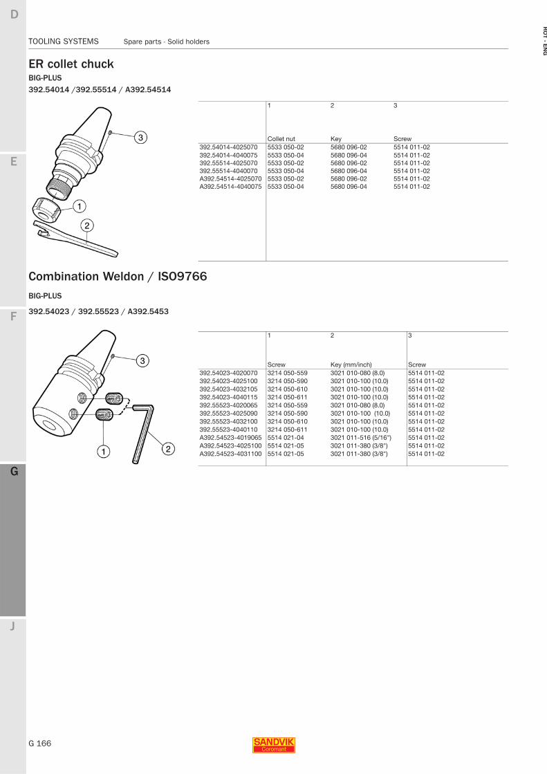
G 166
TOOLING SYSTEMS Spare parts - Solid holders
E
F
G
J
D
G
RO
T - E
NG
TOOLING SYSTEMS Spare parts - Solid holders
ER collet chuckBIG-PLUS392.54014 /392.55514 / A392.54514
Combination Weldon / ISO9766BIG-PLUS
392.54023 / 392.55523 / A392.5453
1 2 3
Collet nut Key Screw392.54014-4025070 5533 050-02 5680 096-02 5514 011-02392.54014-4040075 5533 050-04 5680 096-04 5514 011-02392.55514-4025070 5533 050-02 5680 096-02 5514 011-02392.55514-4040070 5533 050-04 5680 096-04 5514 011-02A392.54514-4025070 5533 050-02 5680 096-02 5514 011-02A392.54514-4040075 5533 050-04 5680 096-04 5514 011-02
1 2 3
Screw Key (mm/inch) Screw392.54023-4020070 3214 050-559 3021 010-080 (8.0) 5514 011-02392.54023-4025100 3214 050-590 3021 010-100 (10.0) 5514 011-02392.54023-4032105 3214 050-610 3021 010-100 (10.0) 5514 011-02392.54023-4040115 3214 050-611 3021 010-100 (10.0) 5514 011-02392.55523-4020065 3214 050-559 3021 010-080 (8.0) 5514 011-02392.55523-4025090 3214 050-590 3021 010-100 (10.0) 5514 011-02392.55523-4032100 3214 050-610 3021 010-100 (10.0) 5514 011-02392.55523-4040110 3214 050-611 3021 010-100 (10.0) 5514 011-02A392.54523-4019065 5514 021-04 3021 011-516 (5/16") 5514 011-02A392.54523-4025100 5514 021-05 3021 011-380 (3/8") 5514 011-02A392.54523-4031100 5514 021-05 3021 011-380 (3/8") 5514 011-02
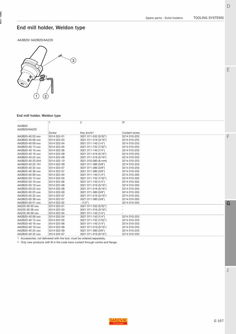
E
G 167
F
G
J
D
G
Spare parts - Solid holders TOOLING SYSTEMS
RO
T -
EN
G
TOOLING SYSTEMS Spare parts - Solid holders
End mill holder, Weldon type
End mill holder, Weldon type
AA3B20/ AA2B20/AA220
1 2 32)
AA3B20AA2B20/AA220
Screw Key (inch)1) Coolant screwAA3B20-40 03 xxx 5514 022-01 3021 011-532 (5/32") 3214 010-253AA3B20-40 06 xxx 5514 022-03 3021 011-316 (3/16") 3214 010-253AA3B20-40 09 xxx 5514 022-04 3021 011-140 (1/4") 3214 010-253AA3B20-40 13 xxx 5514 022-05 3021 011-732 (7/32") 3214 010-253AA3B20-40 16 xxx 5514 022-06 3021 011-140 (1/4") 3214 010-253AA3B20-40 19 xxx 5514 022-08 3021 011-516 (5/16") 3214 010-253AA3B20-40 22 xxx 5514 022-08 3021 011-516 (5/16") 3214 010-253AA3B20-40 25 044 5514 022-10 3021 010-080 (8 mm) 3214 010-253AA3B20-40 25 101 5514 022-09 3021 011-380 (3/8") 3214 010-253AA3B20-40 32 xxx 5514 022-07 3021 011-380 (3/8") 3214 010-253AA3B20-40 38 xxx 5514 022-07 3021 011-380 (3/8") 3214 010-253AA3B20-50 09 xxx 5514 022-04 3021 011-140 (1/4") 3214 010-355AA3B20-50 13 xxx 5514 022-05 3021 011-732 (7/32") 3214 010-355AA3B20-50 16 xxx 5514 022-06 3021 011-140 (1/4") 3214 010-355AA3B20-50 19 xxx 5514 022-08 3021 011-516 (5/16") 3214 010-355AA3B20-50 22 xxx 5514 022-08 3021 011-516 (5/16") 3214 010-355AA3B20-50 25 xxx 5514 022-09 3021 011-380 (3/8") 3214 010-355AA3B20-50 32 xxx 5514 022-07 3021 011-516 (5/16") 3214 010-355AA3B20-50 38 xxx 5514 022-07 3021 011-380 (3/8") 3214 010-355AA3B20-50 51 xxx 5514 022-02 - (1/2") 3214 010-355AA220-30 03 xxx 5514 022-01 3021 011-532 (5/32") -AA220-30 06 xxx 5514 022-03 3021 011-316 (3/16") -AA220-30 09 xxx 5514 022-04 3021 011-140 (1/4") -AA2B20-40 09 xxx 5514 022-04 3021 011-140 (1/4") 3214 010-253AA2B20-40 13 xxx 5514 022-05 3021 011-732 (7/32") 3214 010-253AA2B20-40 16 xxx 5514 022-06 3021 011-140 (1/4") 3214 010-253AA2B20-40 19 xxx 5514 022-08 3021 011-516 (5/16") 3214 010-253AA2B20-40 25 xxx 5514 022-09 3021 011-380 (3/8") 3214 010-253AA2B20-40 32 xxx 5514 022-07 3021 011-516 (5/16") 3214 010-2531) Accessories, not delivered with the tool, must be ordered separately.2) Only new products with B in the code have coolant through centre and flange.
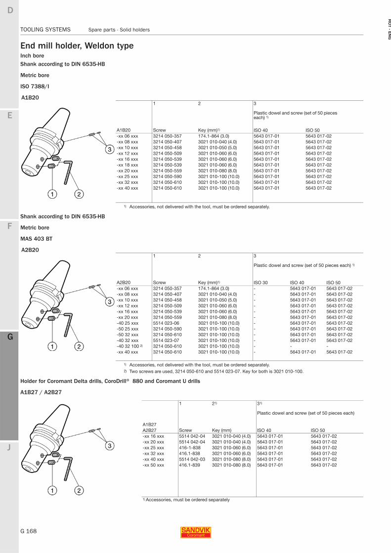
G 168
TOOLING SYSTEMS Spare parts - Solid holders
E
F
G
J
D
G
RO
T - E
NG
TOOLING SYSTEMS Spare parts - Solid holders
End mill holder, Weldon typeInch boreShank according to DIN 6535-HB
Metric bore
ISO 7388/I
Shank according to DIN 6535-HB
Metric bore
MAS 403 BT
Holder for Coromant Delta drills, CoroDrill® 880 and Coromant U drills
A1B27 / A2B27
A1B201 2 3
Plastic dowel and screw (set of 50 pieces each) 1)
A1B20 Screw Key (mm)1) ISO 40 ISO 50-xx 06 xxx 3214 050-357 174.1-864 (3.0) 5643 017-01 5643 017-02-xx 08 xxx 3214 050-407 3021 010-040 (4.0) 5643 017-01 5643 017-02-xx 10 xxx 3214 050-458 3021 010-050 (5.0) 5643 017-01 5643 017-02-xx 12 xxx 3214 050-509 3021 010-060 (6.0) 5643 017-01 5643 017-02-xx 16 xxx 3214 050-539 3021 010-060 (6.0) 5643 017-01 5643 017-02-xx 18 xxx 3214 050-539 3021 010-060 (6.0) 5643 017-01 5643 017-02-xx 20 xxx 3214 050-559 3021 010-080 (8.0) 5643 017-01 5643 017-02-xx 25 xxx 3214 050-590 3021 010-100 (10.0) 5643 017-01 5643 017-02-xx 32 xxx 3214 050-610 3021 010-100 (10.0) 5643 017-01 5643 017-02-xx 40 xxx 3214 050-610 3021 010-100 (10.0) 5643 017-01 5643 017-02
1) Accessories, not delivered with the tool, must be ordered separately.
A2B201 2 3
Plastic dowel and screw (set of 50 pieces each) 1)
A2B20 Screw Key (mm)1) ISO 30 ISO 40 ISO 50-xx 06 xxx 3214 050-357 174.1-864 (3.0) - 5643 017-01 5643 017-02-xx 08 xxx 3214 050-407 3021 010-040 (4.0) - 5643 017-01 5643 017-02-xx 10 xxx 3214 050-458 3021 010-050 (5.0) - 5643 017-01 5643 017-02-xx 12 xxx 3214 050-509 3021 010-060 (6.0) - 5643 017-01 5643 017-02-xx 16 xxx 3214 050-539 3021 010-060 (6.0) - 5643 017-01 5643 017-02-xx 20 xxx 3214 050-559 3021 010-080 (8.0) - 5643 017-01 5643 017-02-40 25 xxx 5514 023-06 3021 010-100 (10.0) - 5643 017-01 5643 017-02-50 25 xxx 3214 050-590 3021 010-100 (10.0) - 5643 017-01 5643 017-02-50 32 xxx 3214 050-610 3021 010-100 (10.0) - 5643 017-01 5643 017-02-40 32 xxx 5514 023-07 3021 010-100 (10.0) - 5643 017-01 5643 017-02-40 32 100 2) 3214 050-610 3021 010-100 (10.0) - - --xx 40 xxx 3214 050-610 3021 010-100 (10.0) - 5643 017-01 5643 017-02
1) Accessories, not delivered with the tool, must be ordered separately.2) Two screws are used, 3214 050-610 and 5514 023-07. Key for both is 3021 010-100.
1 21) 31)
Plastic dowel and screw (set of 50 pieces each)
Key (mm)A1B27
ScrewA2B27 ISO 40 ISO 50-xx 16 xxx 5514 042-04 3021 010-040 (4.0) 5643 017-01 5643 017-02-xx 20 xxx 5514 042-04 3021 010-040 (4.0) 5643 017-01 5643 017-02-xx 25 xxx 416-1-838 3021 010-060 (6.0) 5643 017-01 5643 017-02-xx 32 xxx 416.1-838 3021 010-060 (6.0) 5643 017-01 5643 017-02-xx 40 xxx 5514 042-03 3021 010-080 (8.0) 5643 017-01 5643 017-02-xx 50 xxx 416.1-839 3021 010-080 (8.0) 5643 017-01 5643 017-02
1) Accessories, must be ordered separately
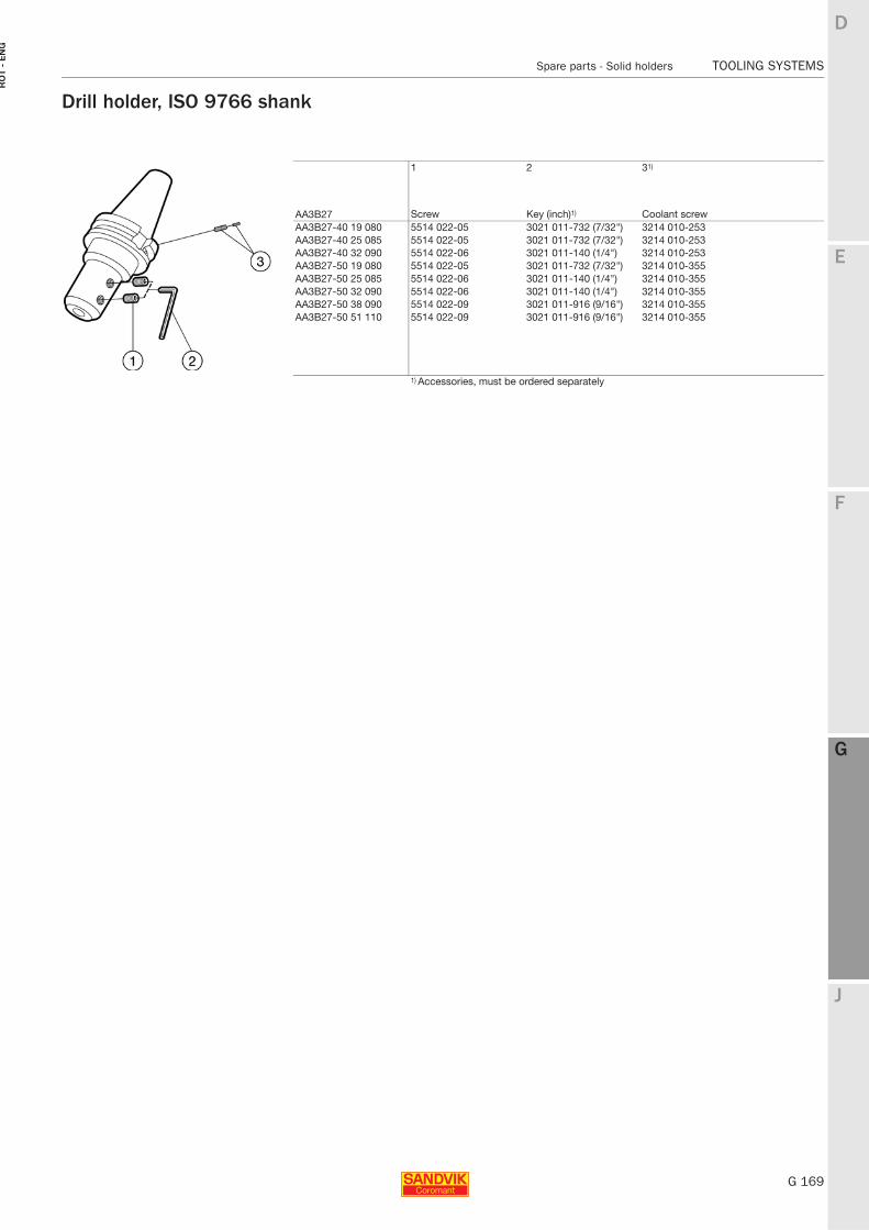
E
G 169
F
G
J
D
G
Spare parts - Solid holders TOOLING SYSTEMS
RO
T -
EN
G
TOOLING SYSTEMS Spare parts - Solid holders
Drill holder, ISO 9766 shank
1 2 31)
Screw Key (inch)1) Coolant screwAA3B27AA3B27-40 19 080 5514 022-05 3021 011-732 (7/32") 3214 010-253AA3B27-40 25 085 5514 022-05 3021 011-732 (7/32") 3214 010-253AA3B27-40 32 090 5514 022-06 3021 011-140 (1/4") 3214 010-253AA3B27-50 19 080 5514 022-05 3021 011-732 (7/32") 3214 010-355AA3B27-50 25 085 5514 022-06 3021 011-140 (1/4") 3214 010-355AA3B27-50 32 090 5514 022-06 3021 011-140 (1/4") 3214 010-355AA3B27-50 38 090 5514 022-09 3021 011-916 (9/16") 3214 010-355AA3B27-50 51 110 5514 022-09 3021 011-916 (9/16") 3214 010-355
1) Accessories, must be ordered separately
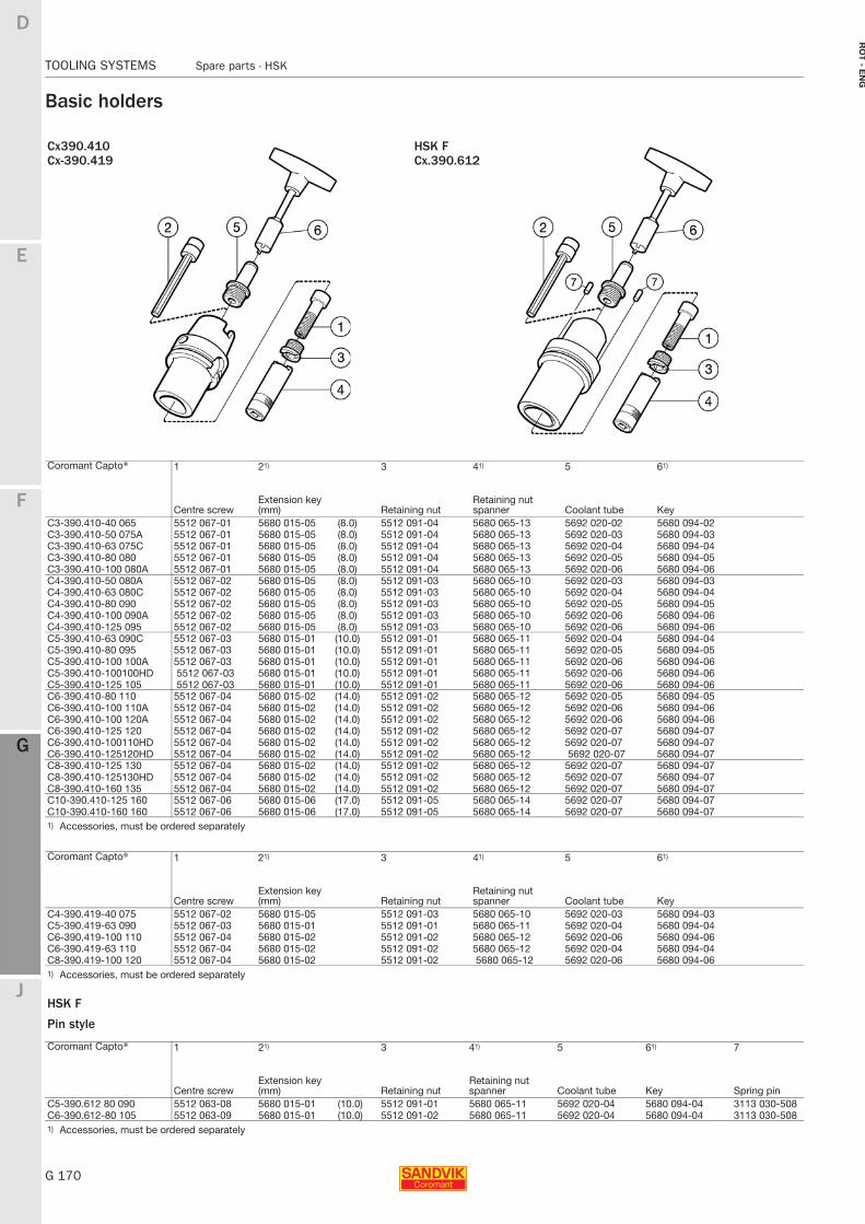
G 170
TOOLING SYSTEMS Spare parts - HSK
E
F
G
J
D
G
RO
T - E
NG
TOOLING SYSTEMS Spare parts − HSK
Basic holders
Cx390.410 HSK FCx-390.419 Cx.390.612
Coromant Capto® 1 21) 3 41) 5 61)
Centre screwExtension key (mm) Retaining nut
Retaining nut spanner Coolant tube Key
C3-390.410-40 065 5512 067-01 5680 015-05 (8.0) 5512 091-04 5680 065-13 5692 020-02 5680 094-02C3-390.410-50 075A 5512 067-01 5680 015-05 (8.0) 5512 091-04 5680 065-13 5692 020-03 5680 094-03C3-390.410-63 075C 5512 067-01 5680 015-05 (8.0) 5512 091-04 5680 065-13 5692 020-04 5680 094-04C3-390.410-80 080 5512 067-01 5680 015-05 (8.0) 5512 091-04 5680 065-13 5692 020-05 5680 094-05C3-390.410-100 080A 5512 067-01 5680 015-05 (8.0) 5512 091-04 5680 065-13 5692 020-06 5680 094-06C4-390.410-50 080A 5512 067-02 5680 015-05 (8.0) 5512 091-03 5680 065-10 5692 020-03 5680 094-03C4-390.410-63 080C 5512 067-02 5680 015-05 (8.0) 5512 091-03 5680 065-10 5692 020-04 5680 094-04C4-390.410-80 090 5512 067-02 5680 015-05 (8.0) 5512 091-03 5680 065-10 5692 020-05 5680 094-05C4-390.410-100 090A 5512 067-02 5680 015-05 (8.0) 5512 091-03 5680 065-10 5692 020-06 5680 094-06C4-390.410-125 095 5512 067-02 5680 015-05 (8.0) 5512 091-03 5680 065-10 5692 020-06 5680 094-06C5-390.410-63 090C 5512 067-03 5680 015-01 (10.0) 5512 091-01 5680 065-11 5692 020-04 5680 094-04C5-390.410-80 095 5512 067-03 5680 015-01 (10.0) 5512 091-01 5680 065-11 5692 020-05 5680 094-05C5-390.410-100 100A 5512 067-03 5680 015-01 (10.0) 5512 091-01 5680 065-11 5692 020-06 5680 094-06C5-390.410-100100HD 5512 067-03 5680 015-01 (10.0) 5512 091-01 5680 065-11 5692 020-06 5680 094-06C5-390.410-125 105 5512 067-03 5680 015-01 (10.0) 5512 091-01 5680 065-11 5692 020-06 5680 094-06C6-390.410-80 110 5512 067-04 5680 015-02 (14.0) 5512 091-02 5680 065-12 5692 020-05 5680 094-05C6-390.410-100 110A 5512 067-04 5680 015-02 (14.0) 5512 091-02 5680 065-12 5692 020-06 5680 094-06C6-390.410-100 120A 5512 067-04 5680 015-02 (14.0) 5512 091-02 5680 065-12 5692 020-06 5680 094-06C6-390.410-125 120 5512 067-04 5680 015-02 (14.0) 5512 091-02 5680 065-12 5692 020-07 5680 094-07C6-390.410-100110HD 5512 067-04 5680 015-02 (14.0) 5512 091-02 5680 065-12 5692 020-07 5680 094-07C6-390.410-125120HD 5512 067-04 5680 015-02 (14.0) 5512 091-02 5680 065-12 5692 020-07 5680 094-07C8-390.410-125 130 5512 067-04 5680 015-02 (14.0) 5512 091-02 5680 065-12 5692 020-07 5680 094-07C8-390.410-125130HD 5512 067-04 5680 015-02 (14.0) 5512 091-02 5680 065-12 5692 020-07 5680 094-07C8-390.410-160 135 5512 067-04 5680 015-02 (14.0) 5512 091-02 5680 065-12 5692 020-07 5680 094-07C10-390.410-125 160 5512 067-06 5680 015-06 (17.0) 5512 091-05 5680 065-14 5692 020-07 5680 094-07C10-390.410-160 160 5512 067-06 5680 015-06 (17.0) 5512 091-05 5680 065-14 5692 020-07 5680 094-071) Accessories, must be ordered separately
Coromant Capto® 1 21) 3 41) 5 61)
Centre screwExtension key (mm) Retaining nut
Retaining nut spanner Coolant tube Key
C4-390.419-40 075 5512 067-02 5680 015-05 5512 091-03 5680 065-10 5692 020-03 5680 094-03C5-390.419-63 090 5512 067-03 5680 015-01 5512 091-01 5680 065-11 5692 020-04 5680 094-04C6-390.419-100 110 5512 067-04 5680 015-02 5512 091-02 5680 065-12 5692 020-06 5680 094-06C6-390.419-63 110 5512 067-04 5680 015-02 5512 091-02 5680 065-12 5692 020-04 5680 094-04C8-390.419-100 120 5512 067-04 5680 015-02 5512 091-02 5680 065-12 5692 020-06 5680 094-061) Accessories, must be ordered separately
HSK F
Pin style
Coromant Capto® 1 21) 3 41) 5 61) 7
Centre screwExtension key (mm) Retaining nut
Retaining nut spanner Coolant tube Key Spring pin
C5-390.612 80 090 5512 063-08 5680 015-01 (10.0) 5512 091-01 5680 065-11 5692 020-04 5680 094-04 3113 030-508C6-390.612-80 105 5512 063-09 5680 015-01 (10.0) 5512 091-02 5680 065-11 5692 020-04 5680 094-04 3113 030-5081) Accessories, must be ordered separately
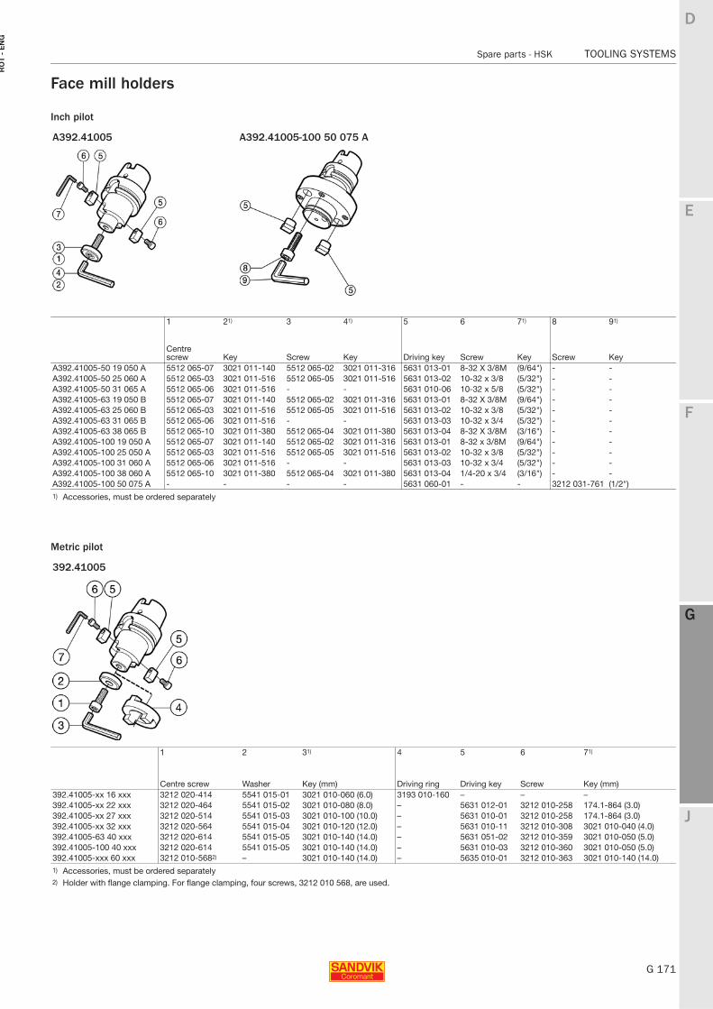
E
G 171
F
G
J
D
G
Spare parts - HSK TOOLING SYSTEMS
RO
T -
EN
G
TOOLING SYSTEMS Spare parts − HSK
Face mill holders
Inch pilot
Metric pilot
A392.41005 A392.41005-100 50 075 A
1 21) 3 41) 5 6 71) 8 91)
Centre screw Key Screw Key Driving key Screw Key Screw Key
A392.41005-50 19 050 A 5512 065-07 3021 011-140 5512 065-02 3021 011-316 5631 013-01 8-32 X 3/8M (9/64") - -A392.41005-50 25 060 A 5512 065-03 3021 011-516 5512 065-05 3021 011-516 5631 013-02 10-32 x 3/8 (5/32") - -A392.41005-50 31 065 A 5512 065-06 3021 011-516 - - 5631 010-06 10-32 x 5/8 (5/32") - -A392.41005-63 19 050 B 5512 065-07 3021 011-140 5512 065-02 3021 011-316 5631 013-01 8-32 X 3/8M (9/64") - -A392.41005-63 25 060 B 5512 065-03 3021 011-516 5512 065-05 3021 011-516 5631 013-02 10-32 x 3/8 (5/32") - -A392.41005-63 31 065 B 5512 065-06 3021 011-516 - - 5631 013-03 10-32 x 3/4 (5/32") - -A392.41005-63 38 065 B 5512 065-10 3021 011-380 5512 065-04 3021 011-380 5631 013-04 8-32 X 3/8M (3/16") - -A392.41005-100 19 050 A 5512 065-07 3021 011-140 5512 065-02 3021 011-316 5631 013-01 8-32 x 3/8M (9/64") - -A392.41005-100 25 050 A 5512 065-03 3021 011-516 5512 065-05 3021 011-516 5631 013-02 10-32 x 3/8 (5/32") - -A392.41005-100 31 060 A 5512 065-06 3021 011-516 - - 5631 013-03 10-32 x 3/4 (5/32") - -A392.41005-100 38 060 A 5512 065-10 3021 011-380 5512 065-04 3021 011-380 5631 013-04 1/4-20 x 3/4 (3/16") - -A392.41005-100 50 075 A - - - - 5631 060-01 - - 3212 031-761 (1/2")1) Accessories, must be ordered separately
392.41005
1 2 31) 4 5 6 71)
Centre screw Washer Key (mm) Driving ring Driving key Screw Key (mm)392.41005-xx 16 xxx 3212 020-414 5541 015-01 3021 010-060 (6.0) 3193 010-160 – – –392.41005-xx 22 xxx 3212 020-464 5541 015-02 3021 010-080 (8.0) – 5631 012-01 3212 010-258 174.1-864 (3.0)392.41005-xx 27 xxx 3212 020-514 5541 015-03 3021 010-100 (10.0) – 5631 010-01 3212 010-258 174.1-864 (3.0)392.41005-xx 32 xxx 3212 020-564 5541 015-04 3021 010-120 (12.0) – 5631 010-11 3212 010-308 3021 010-040 (4.0)392.41005-63 40 xxx 3212 020-614 5541 015-05 3021 010-140 (14.0) – 5631 051-02 3212 010-359 3021 010-050 (5.0)392.41005-100 40 xxx 3212 020-614 5541 015-05 3021 010-140 (14.0) – 5631 010-03 3212 010-360 3021 010-050 (5.0)392.41005-xxx 60 xxx 3212 010-5682) – 3021 010-140 (14.0) – 5635 010-01 3212 010-363 3021 010-140 (14.0)1) Accessories, must be ordered separately 2) Holder with flange clamping. For flange clamping, four screws, 3212 010 568, are used.
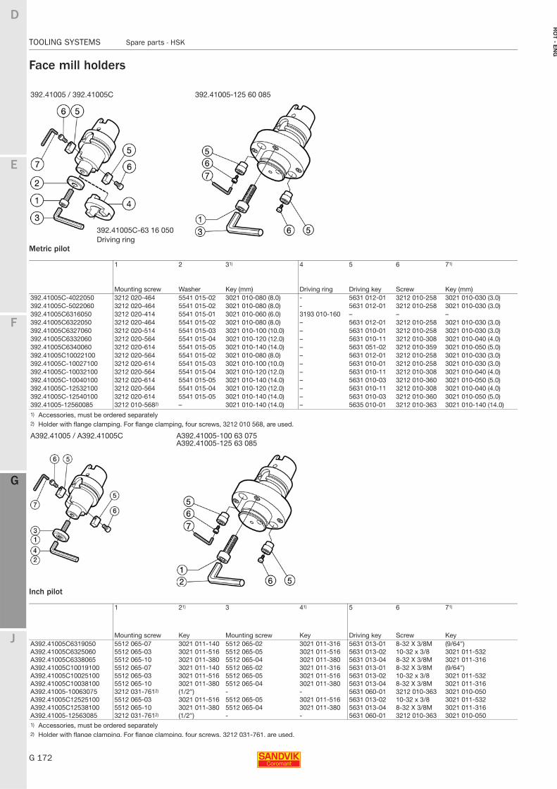
G 172
TOOLING SYSTEMS Spare parts - HSK
E
F
G
J
D
G
RO
T - E
NG
TOOLING SYSTEMS Spare parts − HSK
Face mill holders
Metric pilot
Inch pilot
392.41005 / 392.41005C 392.41005-125 60 085
1 2 31) 4 5 6 71)
Mounting screw Washer Key (mm) Driving ring Driving key Screw Key (mm)392.41005C-4022050 3212 020-464 5541 015-02 3021 010-080 (8.0) - 5631 012-01 3212 010-258 3021 010-030 (3.0)392.41005C-5022060 3212 020-464 5541 015-02 3021 010-080 (8.0) - 5631 012-01 3212 010-258 3021 010-030 (3.0)392.41005C6316050 3212 020-414 5541 015-01 3021 010-060 (6.0) 3193 010-160 – – –392.41005C6322050 3212 020-464 5541 015-02 3021 010-080 (8.0) – 5631 012-01 3212 010-258 3021 010-030 (3.0)392.41005C6327060 3212 020-514 5541 015-03 3021 010-100 (10.0) – 5631 010-01 3212 010-258 3021 010-030 (3.0)392.41005C6332060 3212 020-564 5541 015-04 3021 010-120 (12.0) – 5631 010-11 3212 010-308 3021 010-040 (4.0)392.41005C6340060 3212 020-614 5541 015-05 3021 010-140 (14.0) – 5631 051-02 3212 010-359 3021 010-050 (5.0)392.41005C10022100 3212 020-564 5541 015-02 3021 010-080 (8.0) – 5631 012-01 3212 010-258 3021 010-030 (3.0)392.41005C-10027100 3212 020-614 5541 015-03 3021 010-100 (10.0) – 5631 010-01 3212 010-258 3021 010-030 (3.0)392.41005C-10032100 3212 020-564 5541 015-04 3021 010-120 (12.0) – 5631 010-11 3212 010-308 3021 010-040 (4.0)392.41005C-10040100 3212 020-614 5541 015-05 3021 010-140 (14.0) – 5631 010-03 3212 010-360 3021 010-050 (5.0)392.41005C-12532100 3212 020-564 5541 015-04 3021 010-120 (12.0) – 5631 010-11 3212 010-308 3021 010-040 (4.0)392.41005C-12540100 3212 020-614 5541 015-05 3021 010-140 (14.0) – 5631 010-03 3212 010-360 3021 010-050 (5.0)392.41005-12560085 3212 010-5682) – 3021 010-140 (14.0) – 5635 010-01 3212 010-363 3021 010-140 (14.0)1) Accessories, must be ordered separately 2) Holder with flange clamping. For flange clamping, four screws, 3212 010 568, are used.
A392.41005 / A392.41005C A392.41005-100 63 075A392.41005-125 63 085
1 21) 3 41) 5 6 71)
Mounting screw Key Mounting screw Key Driving key Screw KeyA392.41005C6319050 5512 065-07 3021 011-140 5512 065-02 3021 011-316 5631 013-01 8-32 X 3/8M (9/64")A392.41005C6325060 5512 065-03 3021 011-516 5512 065-05 3021 011-516 5631 013-02 10-32 x 3/8 3021 011-532A392.41005C6338065 5512 065-10 3021 011-380 5512 065-04 3021 011-380 5631 013-04 8-32 X 3/8M 3021 011-316A392.41005C10019100 5512 065-07 3021 011-140 5512 065-02 3021 011-316 5631 013-01 8-32 X 3/8M (9/64")A392.41005C10025100 5512 065-03 3021 011-516 5512 065-05 3021 011-516 5631 013-02 10-32 x 3/8 3021 011-532A392.41005C10038100 5512 065-10 3021 011-380 5512 065-04 3021 011-380 5631 013-04 8-32 X 3/8M 3021 011-316A392.41005-10063075 3212 031-7612) (1/2") - - 5631 060-01 3212 010-363 3021 010-050A392.41005C12525100 5512 065-03 3021 011-516 5512 065-05 3021 011-516 5631 013-02 10-32 x 3/8 3021 011-532A392.41005C12538100 5512 065-10 3021 011-380 5512 065-04 3021 011-380 5631 013-04 8-32 X 3/8M 3021 011-316A392.41005-12563085 3212 031-7612) (1/2") - - 5631 060-01 3212 010-363 3021 010-0501) Accessories, must be ordered separately 2) Holder with flange clamping. For flange clamping, four screws, 3212 031-761, are used.
392.41005C-63 16 050Driving ring
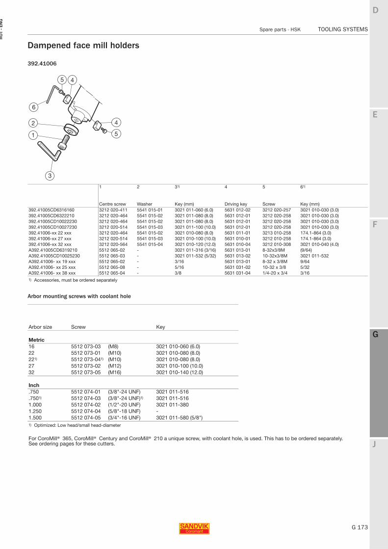
E
G 173
F
G
J
D
G
Spare parts - HSK TOOLING SYSTEMS
RO
T -
EN
G
TOOLING SYSTEMS Spare parts − HSK
Dampened face mill holders
392.41006
Arbor mounting screws with coolant hole
1 2 31) 4 5 61)
Centre screw Washer Key (mm) Driving key Screw Key (mm)392.41005CD6316160 3212 020-411 5541 015-01 3021 011-060 (6.0) 5631 012-02 3212 020-257 3021 010-030 (3.0)392.41005CD6322210 3212 020-464 5541 015-02 3021 011-080 (8.0) 5631 012-01 3212 020-258 3021 010-030 (3.0)392.41005CD10022230 3212 020-464 5541 015-02 3021 011-080 (8.0) 5631 012-01 3212 020-258 3021 010-030 (3.0)392.41005CD10027230 3212 020-514 5541 015-03 3021 011-100 (10.0) 5631 012-01 3212 020-258 3021 010-030 (3.0)392.41006-xx 22 xxx 3212 020-464 5541 015-02 3021 010-080 (8.0) 5631 011-01 3213 010-258 174.1-864 (3.0)392.41006-xx 27 xxx 3212 020-514 5541 015-03 3021 010-100 (10.0) 5631 010-01 3212 010-258 174.1-864 (3.0)392.41006-xx 32 xxx 3212 020-564 5541 015-04 3021 010-120 (12.0) 5631 010-04 3212 010-308 3021 010-040 (4.0)A392.41005CD6319210 5512 065-02 - 3021 011-316 (3/16) 5631 013-01 8-32x3/8M (9/64)A392.41005CD10025230 5512 065-03 - 3021 011-532 (5/32) 5631 013-02 10-32x3/8M 3021 011-532A392.41006- xx 19 xxx 5512 065-02 - 3/16 5631 013-01 8-32 x 3/8M 9/64A392.41006- xx 25 xxx 5512 065-08 - 5/16 5631 031-02 10-32 x 3/8 5/32A392.41006- xx 38 xxx 5512 065-04 - 3/8 5631 031-04 1/4-20 x 3/4 3/161) Accessories, must be ordered separately
Arbor size Screw Key
Metric16 5512 073-03 (M8) 3021 010-060 (6.0)22 5512 073-01 (M10) 3021 010-080 (8.0)221) 5512 073-041) (M10) 3021 010-080 (8.0)27 5512 073-02 (M12) 3021 010-100 (10.0)32 5512 073-05 (M16) 3021 010-140 (12.0)
Inch .750 5512 074-01 (3/8"-24 UNF) 3021 011-516.7501) 5512 074-03 (3/8"-24 UNF)1) 3021 011-5161.000 5512 074-02 (1/2"-20 UNF) 3021 011-3801.250 5512 074-04 (5/8"-18 UNF) -1.500 5512 074-05 (3/4"-16 UNF) 3021 011-580 (5/8")1) Optimized: Low head/small head-diameter
For CoroMill® 365, CoroMill® Century and CoroMill® 210 a unique screw, with coolant hole, is used. This has to be ordered separately.See ordering pages for these cutters.
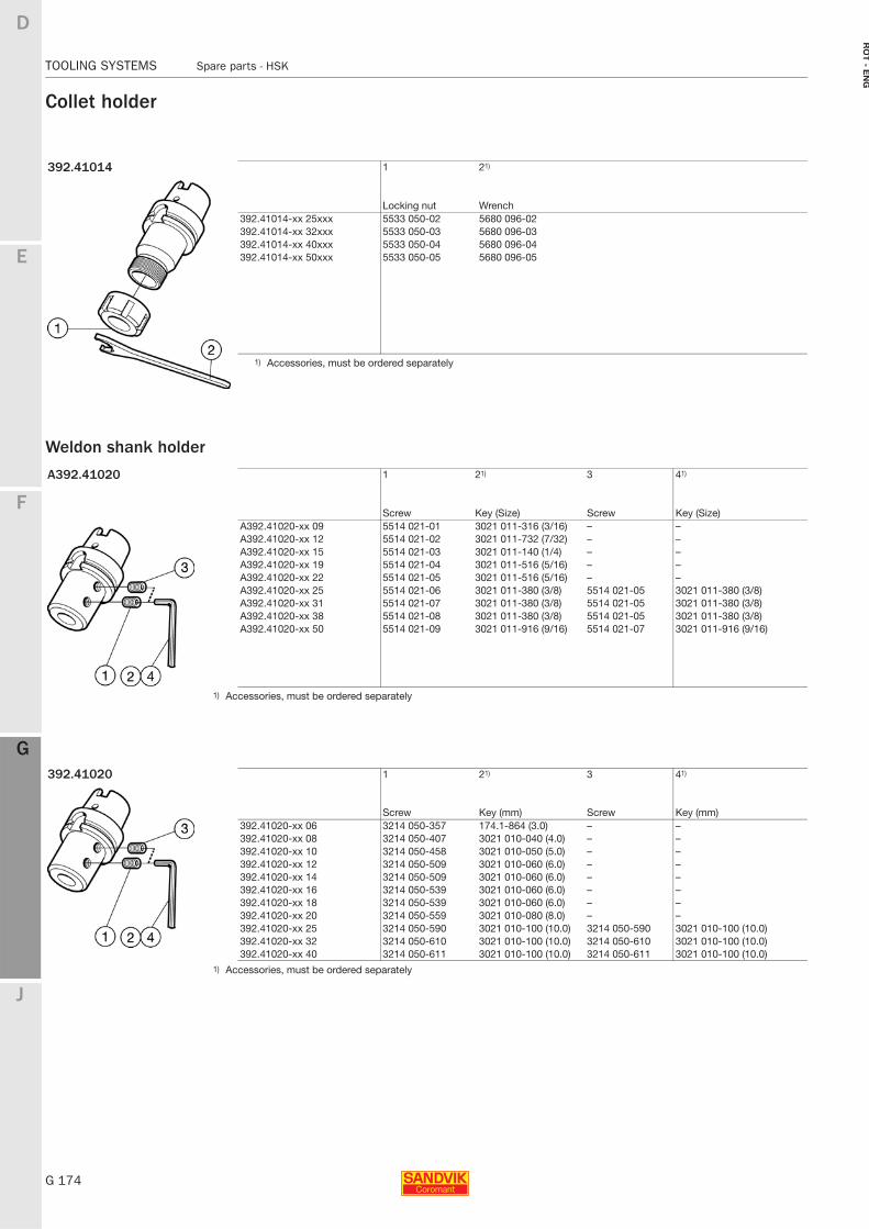
G 174
TOOLING SYSTEMS Spare parts - HSK
E
F
G
J
D
G
RO
T - E
NG
TOOLING SYSTEMS Spare parts − HSK
Collet holder
Weldon shank holder
392.41014 1 21)
Locking nut Wrench392.41014-xx 25xxx 5533 050-02 5680 096-02392.41014-xx 32xxx 5533 050-03 5680 096-03392.41014-xx 40xxx 5533 050-04 5680 096-04392.41014-xx 50xxx 5533 050-05 5680 096-05
1) Accessories, must be ordered separately
A392.41020 1 21) 3 41)
Screw Key (Size) Screw Key (Size)A392.41020-xx 09 5514 021-01 3021 011-316 (3/16) – –A392.41020-xx 12 5514 021-02 3021 011-732 (7/32) – –A392.41020-xx 15 5514 021-03 3021 011-140 (1/4) – –A392.41020-xx 19 5514 021-04 3021 011-516 (5/16) – –A392.41020-xx 22 5514 021-05 3021 011-516 (5/16) – –A392.41020-xx 25 5514 021-06 3021 011-380 (3/8) 5514 021-05 3021 011-380 (3/8)A392.41020-xx 31 5514 021-07 3021 011-380 (3/8) 5514 021-05 3021 011-380 (3/8)A392.41020-xx 38 5514 021-08 3021 011-380 (3/8) 5514 021-05 3021 011-380 (3/8)A392.41020-xx 50 5514 021-09 3021 011-916 (9/16) 5514 021-07 3021 011-916 (9/16)
1) Accessories, must be ordered separately
392.41020 1 21) 3 41)
Screw Key (mm) Screw Key (mm)392.41020-xx 06 3214 050-357 174.1-864 (3.0) – –392.41020-xx 08 3214 050-407 3021 010-040 (4.0) – –392.41020-xx 10 3214 050-458 3021 010-050 (5.0) – –392.41020-xx 12 3214 050-509 3021 010-060 (6.0) – –392.41020-xx 14 3214 050-509 3021 010-060 (6.0) – –392.41020-xx 16 3214 050-539 3021 010-060 (6.0) – –392.41020-xx 18 3214 050-539 3021 010-060 (6.0) – –392.41020-xx 20 3214 050-559 3021 010-080 (8.0) – –392.41020-xx 25 3214 050-590 3021 010-100 (10.0) 3214 050-590 3021 010-100 (10.0)392.41020-xx 32 3214 050-610 3021 010-100 (10.0) 3214 050-610 3021 010-100 (10.0)392.41020-xx 40 3214 050-611 3021 010-100 (10.0) 3214 050-611 3021 010-100 (10.0)
1) Accessories, must be ordered separately
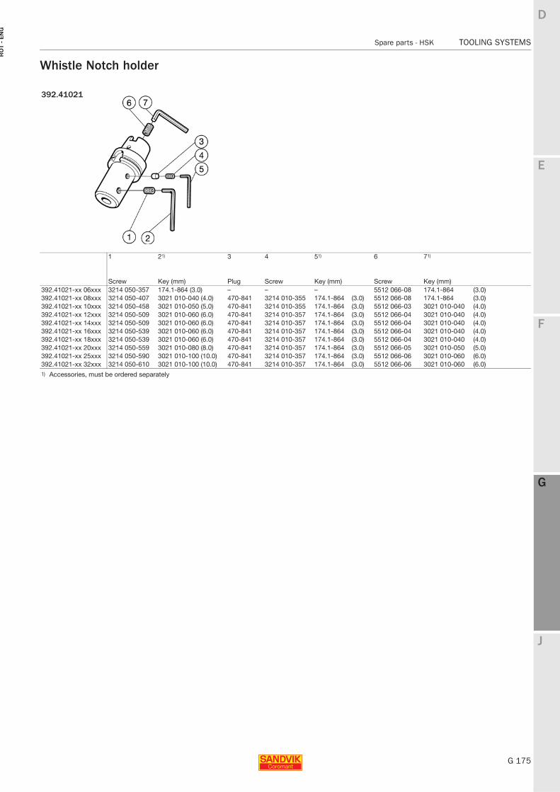
E
G 175
F
G
J
D
G
Spare parts - HSK TOOLING SYSTEMS
RO
T -
EN
G
TOOLING SYSTEMS Spare parts − HSK
Whistle Notch holder
392.41021
1 21) 3 4 51) 6 71)
Screw Key (mm) Plug Screw Key (mm) Screw Key (mm)392.41021-xx 06xxx 3214 050-357 174.1-864 (3.0) – – – 5512 066-08 174.1-864 (3.0)392.41021-xx 08xxx 3214 050-407 3021 010-040 (4.0) 470-841 3214 010-355 174.1-864 (3.0) 5512 066-08 174.1-864 (3.0)392.41021-xx 10xxx 3214 050-458 3021 010-050 (5.0) 470-841 3214 010-355 174.1-864 (3.0) 5512 066-03 3021 010-040 (4.0)392.41021-xx 12xxx 3214 050-509 3021 010-060 (6.0) 470-841 3214 010-357 174.1-864 (3.0) 5512 066-04 3021 010-040 (4.0)392.41021-xx 14xxx 3214 050-509 3021 010-060 (6.0) 470-841 3214 010-357 174.1-864 (3.0) 5512 066-04 3021 010-040 (4.0)392.41021-xx 16xxx 3214 050-539 3021 010-060 (6.0) 470-841 3214 010-357 174.1-864 (3.0) 5512 066-04 3021 010-040 (4.0)392.41021-xx 18xxx 3214 050-539 3021 010-060 (6.0) 470-841 3214 010-357 174.1-864 (3.0) 5512 066-04 3021 010-040 (4.0)392.41021-xx 20xxx 3214 050-559 3021 010-080 (8.0) 470-841 3214 010-357 174.1-864 (3.0) 5512 066-05 3021 010-050 (5.0)392.41021-xx 25xxx 3214 050-590 3021 010-100 (10.0) 470-841 3214 010-357 174.1-864 (3.0) 5512 066-06 3021 010-060 (6.0)392.41021-xx 32xxx 3214 050-610 3021 010-100 (10.0) 470-841 3214 010-357 174.1-864 (3.0) 5512 066-06 3021 010-060 (6.0)1) Accessories, must be ordered separately
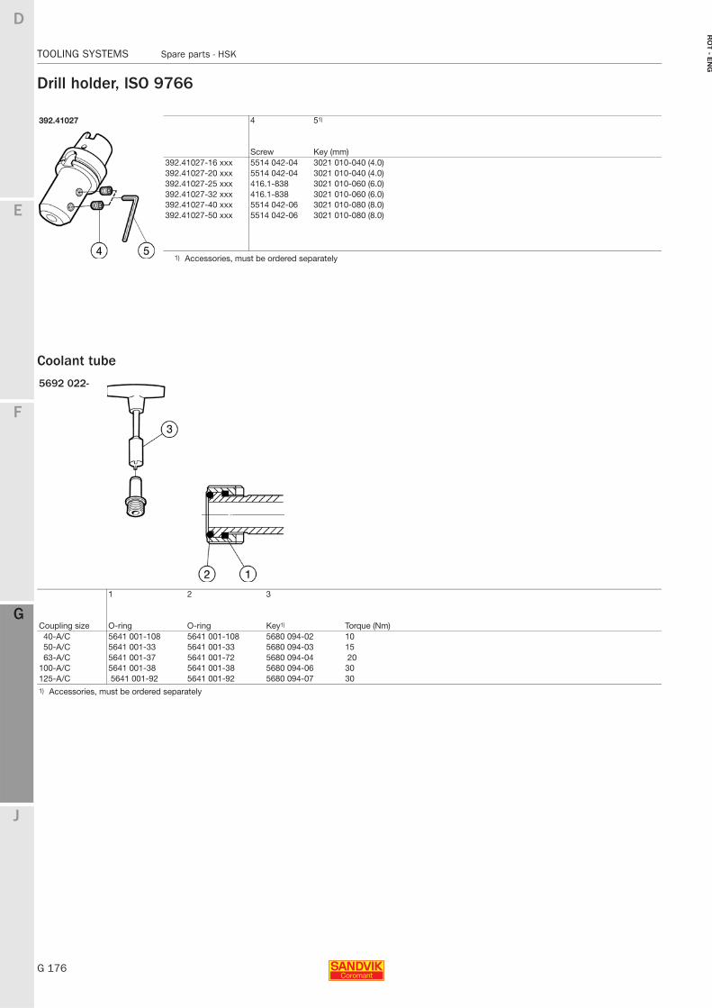
G 176
TOOLING SYSTEMS Spare parts - HSK
E
F
G
J
D
G
RO
T - E
NG
TOOLING SYSTEMS Spare parts − HSK
Drill holder, ISO 9766
Coolant tube
392.41027 4 51)
Screw Key (mm)392.41027-16 xxx 5514 042-04 3021 010-040 (4.0)392.41027-20 xxx 5514 042-04 3021 010-040 (4.0)392.41027-25 xxx 416.1-838 3021 010-060 (6.0)392.41027-32 xxx 416.1-838 3021 010-060 (6.0)392.41027-40 xxx 5514 042-06 3021 010-080 (8.0)392.41027-50 xxx 5514 042-06 3021 010-080 (8.0)
1) Accessories, must be ordered separately
5692 022-
Coupling size
1 2 3
O-ring O-ring Key1) Torque (Nm) 40-A/C 5641 001-108 5641 001-108 5680 094-02 10 50-A/C 5641 001-33 5641 001-33 5680 094-03 1563-A/C 5641 001-37 5641 001-72 5680 094-04 20
100-A/C 5641 001-38 5641 001-38 5680 094-06 30125-A/C 5641 001-92 5641 001-92 5680 094-07 301) Accessories, must be ordered separately
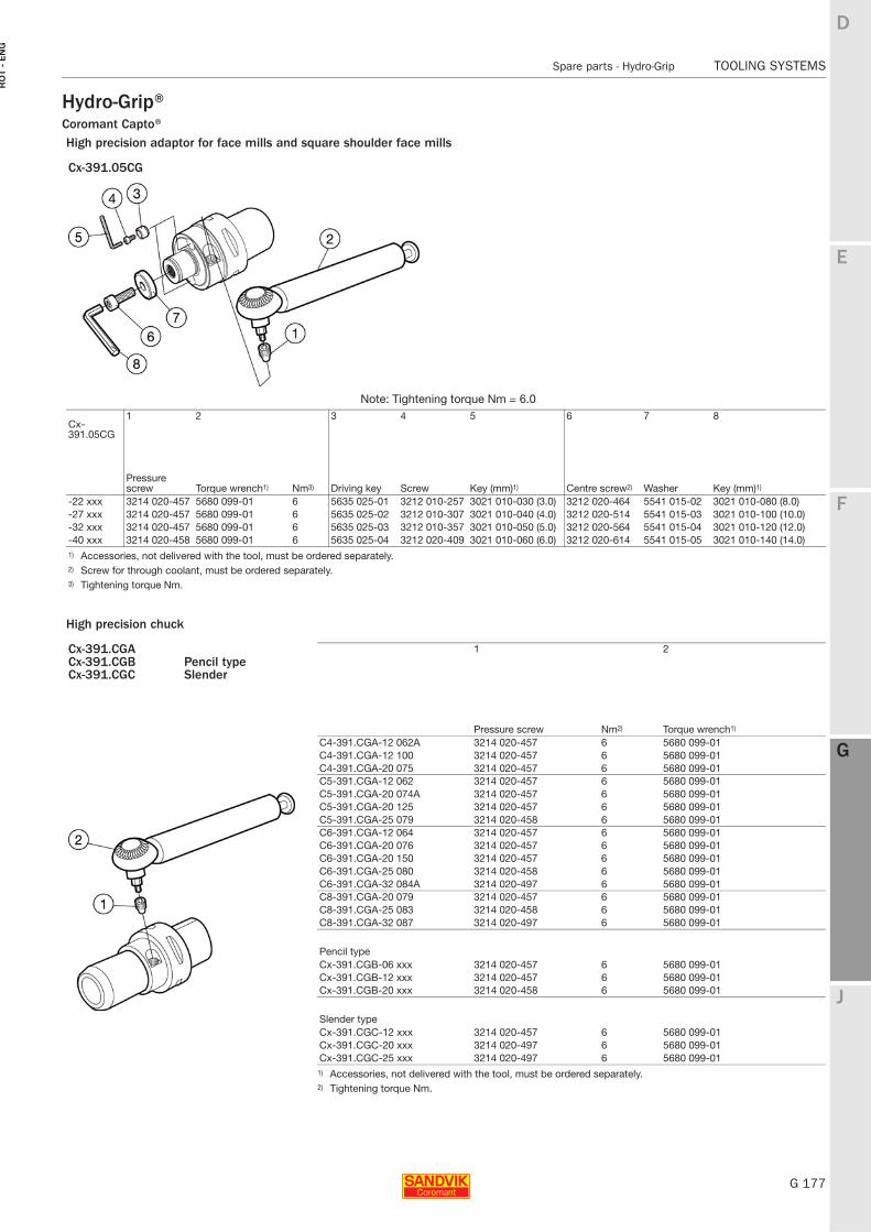
E
G 177
F
G
J
D
G
Spare parts - Hydro-Grip TOOLING SYSTEMS
RO
T -
EN
G
TOOLING SYSTEMS Spare parts − Hydro-Grip
Hydro-Grip®Coromant Capto® High precision adaptor for face mills and square shoulder face mills
High precision chuck
Cx-391.05CG
Note: Tightening torque Nm = 6.01 2 3 4 5 6 7 8
Cx-391.05CG
Pressure screw Torque wrench1) Nm3) Driving key Screw Key (mm)1) Centre screw2) Washer Key (mm)1)
-22 xxx 3214 020-457 5680 099-01 6 5635 025-01 3212 010-257 3021 010-030 (3.0) 3212 020-464 5541 015-02 3021 010-080 (8.0)-27 xxx 3214 020-457 5680 099-01 6 5635 025-02 3212 010-307 3021 010-040 (4.0) 3212 020-514 5541 015-03 3021 010-100 (10.0)-32 xxx 3214 020-457 5680 099-01 6 5635 025-03 3212 010-357 3021 010-050 (5.0) 3212 020-564 5541 015-04 3021 010-120 (12.0)-40 xxx 3214 020-458 5680 099-01 6 5635 025-04 3212 020-409 3021 010-060 (6.0) 3212 020-614 5541 015-05 3021 010-140 (14.0)1) Accessories, not delivered with the tool, must be ordered separately.2) Screw for through coolant, must be ordered separately.3) Tightening torque Nm.
Cx-391.CGA 1 2Cx-391.CGB Pencil typeCx-391.CGC Slender
Pressure screw Nm2) Torque wrench1)
C4-391.CGA-12 062A 3214 020-457 6 5680 099-01C4-391.CGA-12 100 3214 020-457 6 5680 099-01C4-391.CGA-20 075 3214 020-457 6 5680 099-01C5-391.CGA-12 062 3214 020-457 6 5680 099-01C5-391.CGA-20 074A 3214 020-457 6 5680 099-01C5-391.CGA-20 125 3214 020-457 6 5680 099-01C5-391.CGA-25 079 3214 020-458 6 5680 099-01C6-391.CGA-12 064 3214 020-457 6 5680 099-01C6-391.CGA-20 076 3214 020-457 6 5680 099-01C6-391.CGA-20 150 3214 020-457 6 5680 099-01C6-391.CGA-25 080 3214 020-458 6 5680 099-01C6-391.CGA-32 084A 3214 020-497 6 5680 099-01C8-391.CGA-20 079 3214 020-457 6 5680 099-01C8-391.CGA-25 083 3214 020-458 6 5680 099-01C8-391.CGA-32 087 3214 020-497 6 5680 099-01
Pencil typeCx-391.CGB-06 xxx 3214 020-457 6 5680 099-01Cx-391.CGB-12 xxx 3214 020-457 6 5680 099-01Cx-391.CGB-20 xxx 3214 020-458 6 5680 099-01
Slender typeCx-391.CGC-12 xxx 3214 020-457 6 5680 099-01Cx-391.CGC-20 xxx 3214 020-497 6 5680 099-01Cx-391.CGC-25 xxx 3214 020-497 6 5680 099-01
1) Accessories, not delivered with the tool, must be ordered separately.2) Tightening torque Nm.
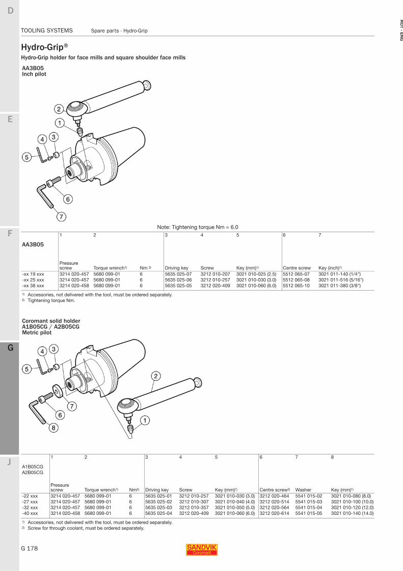
G 178
TOOLING SYSTEMS Spare parts - Hydro-Grip
E
F
G
J
D
G
RO
T - E
NG
TOOLING SYSTEMS Spare parts − Hydro-Grip
Hydro-Grip®Hydro-Grip holder for face mills and square shoulder face mills
AA3B05Inch pilot
Note: Tightening torque Nm = 6.01 2 3 4 5 6 7
AA3B05
Pressure screw Torque wrench1) Nm 3) Driving key Screw Key (mm)1) Centre screw Key (inch)1)
-xx 19 xxx 3214 020-457 5680 099-01 6 5635 025-07 3212 010-207 3021 010-025 (2.5) 5512 065-07 3021 011-140 (1/4")-xx 25 xxx 3214 020-457 5680 099-01 6 5635 025-06 3212 010-257 3021 010-030 (3.0) 5512 065-08 3021 011-516 (5/16")-xx 38 xxx 3214 020-458 5680 099-01 6 5635 025-05 3212 020-409 3021 010-060 (6.0) 5512 065-10 3021 011-380 (3/8")
1) Accessories, not delivered with the tool, must be ordered separately.2) Tightening torque Nm.
Coromant solid holderA1B05CG / A2B05CGMetric pilot
1 2 3 4 5 6 7 8
A1B05CGA2B05CG
Pressure screw Torque wrench1) Nm3) Driving key Screw Key (mm)1) Centre screw2) Washer Key (mm)1)
-22 xxx 3214 020-457 5680 099-01 6 5635 025-01 3212 010-257 3021 010-030 (3.0) 3212 020-464 5541 015-02 3021 010-080 (8.0)-27 xxx 3214 020-457 5680 099-01 6 5635 025-02 3212 010-307 3021 010-040 (4.0) 3212 020-514 5541 015-03 3021 010-100 (10.0)-32 xxx 3214 020-457 5680 099-01 6 5635 025-03 3212 010-357 3021 010-050 (5.0) 3212 020-564 5541 015-04 3021 010-120 (12.0)-40 xxx 3214 020-458 5680 099-01 6 5635 025-04 3212 020-409 3021 010-060 (6.0) 3212 020-614 5541 015-05 3021 010-140 (14.0)
1) Accessories, not delivered with the tool, must be ordered separately.2) Screw for through coolant, must be ordered separately.
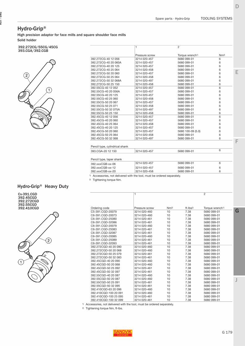
E
G 179
F
G
J
D
G
Spare parts - Hydro-Grip TOOLING SYSTEMS
RO
T -
EN
G
TOOLING SYSTEMS Spare parts − Hydro-Grip
Hydro-Grip®High precision adaptor for face mills and square shoulder face millsSolid holder
Hydro-Grip® Heavy Duty
392.272CG/55CG/45CG 1 2393.CGA/392.CGB
Pressure screw Torque wrench1) Nm2)
392.272CG-40 12 056 3214 020-457 5680 099-01 6392.272CG-40 20 060A 3214 020-457 5680 099-01 6392.272CG-40 20 125 3214 020-457 5680 099-01 6392.272CG-40 25 064 3214 020-458 5680 099-01 6392.272CG-50 20 060 3214 020-457 5680 099-01 6392.272CG-50 25 064 3214 020-458 5680 099-01 6392.272CG-50 32 068A 3214 020-497 5680 099-01 6392.272CG-50 25 150 3214 020-458 5680 099-01 6392.55CG-40 12 052 3214 020-457 5680 099-01 6392.55CG-40 20 056A 3214 020-457 5680 099-01 6392.55CG-40 20 125 3214 020-457 5680 099-01 6392.55CG-40 25 060 3214 020-458 5680 099-01 6392.55CG-50 20 067 3214 020-457 5680 099-01 6392.55CG-50 25 071 3214 020-458 5680 099-01 6392.55CG-50 32 075A 3214 020-497 5680 099-01 6392.55CG-50 25 150 3214 020-458 5680 099-01 6392.45CG-40 12 056 3214 020-457 5680 099-01 6392.45CG-40 20 060 3214 020-457 5680 099-01 6392.45CG-40 25 064 3214 020-458 5680 099-01 6392.45CG-40 20 125 3214 020-457 5680 099-01 6392.45CG-50 20 060 3214 020-457 5680 100-09 (5.0) 6392.45CG-50 25 064 3214 020-458 5680 099-01 6392.45CG-50 32 068 3214 020-497 5680 099-01 6
Pencil type, cylindrical shank
393.CGA-20 12 150 3214 020-457 5680 099-01 6
Pencil type, taper shank
392.xxxCGB-xx-06 3214 020-457 5680 099-01 6
392.xxxCGB-xx-12 3214 020-457 5680 099-01 6392.xxxCGB-xx-20 3214 020-458 5680 099-01 6
1) Accessories, not delivered with the tool, must be ordered separately.2) Tightening torque Nm.
Cx-391.CGD 1 2392.45CGD392.272CGD392.55CGD
Ordering code Pressure screw Nm2) ft-lbs2) Torque wrench1)392.410CGDC5-391.CGD-20079 3214 020-460 10 7.38 5680 099-01C6-391.CGD-20073 3214 020-460 10 7.38 5680 099-01C6-391.CGD-25080 3214 020-461 10 7.38 5680 099-01C6-391.CGD-32086 3214 020-461 10 7.38 5680 099-01C6-391.CGD-20079 3214 020-460 10 7.38 5680 099-01C6-391.CGD-25083 3214 020-461 10 7.38 5680 099-01C6-391.CGD-32087 3214 020-461 10 7.38 5680 099-01C6-391.CGD-20085 3214 020-460 10 7.38 5680 099-01C6-391.CGD-25089 3214 020-461 10 7.38 5680 099-01C6-391.CGD-32093 3214 020-461 10 7.38 5680 099-01392.272CGD-40 20 090 3214 020-460 10 7.38 5680 099-01392.272CGD-50 20 068 3214 020-460 10 7.38 5680 099-01392.272CGD-50 25 079 3214 020-461 10 7.38 5680 099-01392.272CGD-50 32 083 3214 020-461 10 7.38 5680 099-01392.45CGD-40 20 090 3214 020-460 10 7.38 5680 099-01392.45CGD-50 20 068 3214 020-460 10 7.38 5680 099-01392.45CGD-50 25 092 3214 020-461 10 7.38 5680 099-01392.45CGD-50 32 097 3214 020-461 10 7.38 5680 099-01392.55CGD-40 20 087 3214 020-460 10 7.38 5680 099-01392.55CGD-50 20 087 3214 020-460 10 7.38 5680 099-01392.55CGD-50 25 091 3214 020-461 10 7.38 5680 099-01392.55CGD-50 32 095 3214 020-461 10 7.38 5680 099-01392.410CGD-63 20 096 3214 020-460 10 7.38 5680 099-01392.410CGD-100 20 091 3214 020-460 10 7.38 5680 099-01392.410CGD-100 25 095 3214 020-461 10 7.38 5680 099-01392.410CGD-100 32 099 3214 020-461 10 7.38 5680 099-01
1) Accessories, not delivered with the tool, must be ordered separately.2) Tightening torque Nm, ft-lbs.
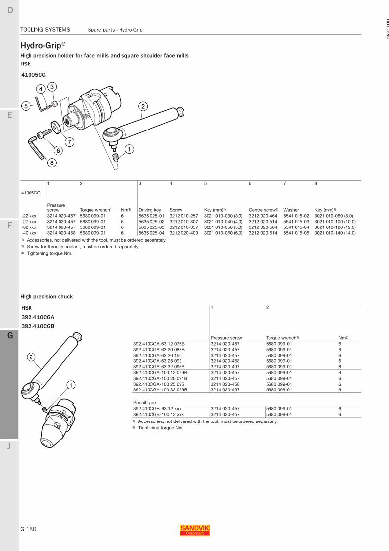
G 180
TOOLING SYSTEMS Spare parts - Hydro-Grip
E
F
G
J
D
G
RO
T - E
NG
TOOLING SYSTEMS Spare parts − Hydro-Grip
Hydro-Grip®High precision holder for face mills and square shoulder face millsHSK
High precision chuck
41005CG
1 2 3 4 5 6 7 8
41005CG
Pressure screw Torque wrench1) Nm3) Driving key Screw Key (mm)1) Centre screw2) Washer Key (mm)1)
-22 xxx 3214 020-457 5680 099-01 6 5635 025-01 3212 010-257 3021 010-030 (3.0) 3212 020-464 5541 015-02 3021 010-080 (8.0)-27 xxx 3214 020-457 5680 099-01 6 5635 025-02 3212 010-307 3021 010-040 (4.0) 3212 020-514 5541 015-03 3021 010-100 (10.0)-32 xxx 3214 020-457 5680 099-01 6 5635 025-03 3212 010-357 3021 010-050 (5.0) 3212 020-564 5541 015-04 3021 010-120 (12.0)-40 xxx 3214 020-458 5680 099-01 6 5635 025-04 3212 020-409 3021 010-060 (6.0) 3212 020-614 5541 015-05 3021 010-140 (14.0)1) Accessories, not delivered with the tool, must be ordered separately.2) Screw for through coolant, must be ordered separately.3) Tightening torque Nm.
HSK 1 2
392.410CGA
392.410CGB
Pressure screw Torque wrench1) Nm2)
392.410CGA-63 12 076B 3214 020-457 5680 099-01 6392.410CGA-63 20 088B 3214 020-457 5680 099-01 6392.410CGA-63 20 150 3214 020-457 5680 099-01 6392.410CGA-63 25 092 3214 020-458 5680 099-01 6392.410CGA-63 32 096A 3214 020-497 5680 099-01 6392.410CGA-100 12 079B 3214 020-457 5680 099-01 6392.410CGA-100 20 091B 3214 020-457 5680 099-01 6392.410CGA-100 25 095 3214 020-458 5680 099-01 6392.410CGA-100 32 099B 3214 020-497 5680 099-01 6
Pencil type392.410CGB-63 12 xxx 3214 020-457 5680 099-01 6392.410CGB-100 12 xxx 3214 020-457 5680 099-01 6
1) Accessories, not delivered with the tool, must be ordered separately.2) Tightening torque Nm.
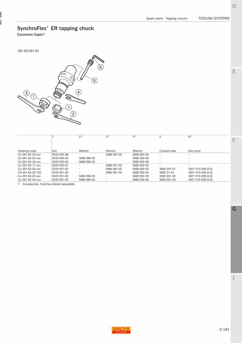
E
G 181
F
G
J
D
G
Spare parts - Tapping chucks TOOLING SYSTEMS
RO
T -
EN
G
TOOLING SYSTEMS Spare parts - Tapping chucks
SynchroFlex® ER tapping chuckCoromant Capto®
391.62/391.63
1 21) 31) 41) 5 61)
Ordering code Nut Wrench Wrench Wrench Coolant tube Key (mm)Cx-391.62-20 xxx 5533 050-08 - 5680 091-02 5680 092-04 - -Cx-391.62-25 xxx 5533 050-02 5680 096-02 - 5680 092-05 - -Cx-391.62-40 xxx 5533 050-04 5680 096-04 - 5680 092-06 - -Cx-391.63-11 xxx 5533 050-07 - 5680 051-03 5680 052-03 - -Cx-391.63-20 xxx 5533 051-02 - 5680 091-02 5680 092-04 5692 031-01 3021 010-030 (3.0)C3-391.63-20 105 5533 051-02 - 5680 091-02 5680 092-04 5692 01-04 3021 010-030 (3.0)Cx-391.63-25 xxx 5533 051-03 5680 096-02 - 5680 092-05 5692 031-02 3021 010-030 (3.0)Cx-391.63-40 xxx 5533 051-05 5680 096-04 - 5680 092-06 5692 031-03 3021 010-030 (3.0)1) Accessories, must be ordered separately
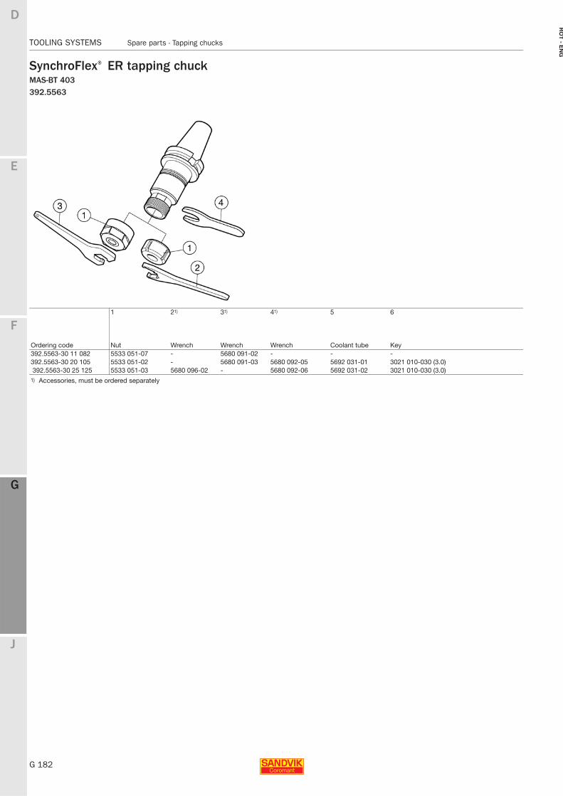
G 182
TOOLING SYSTEMS Spare parts - Tapping chucks
E
F
G
J
D
G
RO
T - E
NG
TOOLING SYSTEMS Spare parts - Tapping chucks
SynchroFlex® ER tapping chuckMAS-BT 403392.5563
1 21) 31) 41) 5 6
Ordering code Nut Wrench Wrench Wrench Coolant tube Key 392.5563-30 11 082 5533 051-07 - 5680 091-02 - - -392.5563-30 20 105 5533 051-02 - 5680 091-03 5680 092-05 5692 031-01 3021 010-030 (3.0)392.5563-30 25 125 5533 051-03 5680 096-02 - 5680 092-06 5692 031-02 3021 010-030 (3.0)
1) Accessories, must be ordered separately
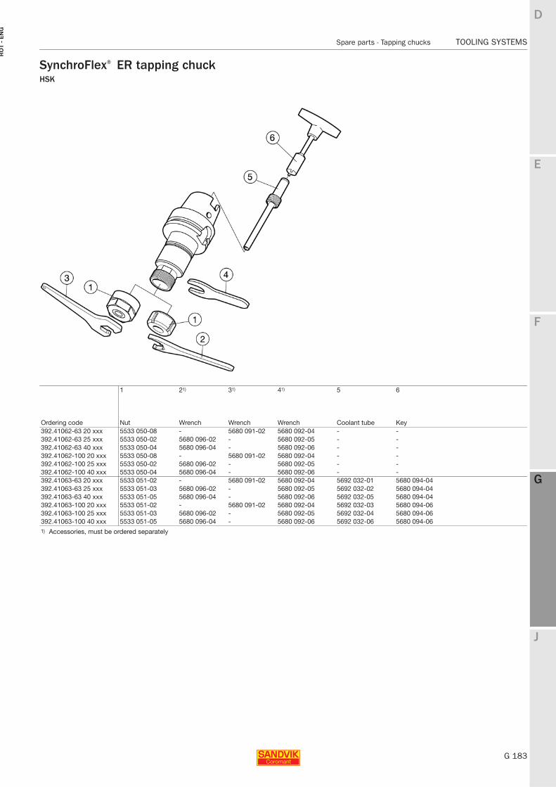
E
G 183
F
G
J
D
G
Spare parts - Tapping chucks TOOLING SYSTEMS
RO
T -
EN
G
TOOLING SYSTEMS Spare parts - Tapping chucks
SynchroFlex® ER tapping chuckHSK
1 21) 31) 41) 5 6
Ordering code Nut Wrench Wrench Wrench Coolant tube Key 392.41062-63 20 xxx 5533 050-08 - 5680 091-02 5680 092-04 - -392.41062-63 25 xxx 5533 050-02 5680 096-02 - 5680 092-05 - -392.41062-63 40 xxx 5533 050-04 5680 096-04 - 5680 092-06 - -392.41062-100 20 xxx 5533 050-08 - 5680 091-02 5680 092-04 - -392.41062-100 25 xxx 5533 050-02 5680 096-02 - 5680 092-05 - -392.41062-100 40 xxx 5533 050-04 5680 096-04 - 5680 092-06 - -392.41063-63 20 xxx 5533 051-02 - 5680 091-02 5680 092-04 5692 032-01 5680 094-04392.41063-63 25 xxx 5533 051-03 5680 096-02 - 5680 092-05 5692 032-02 5680 094-04392.41063-63 40 xxx 5533 051-05 5680 096-04 - 5680 092-06 5692 032-05 5680 094-04392.41063-100 20 xxx 5533 051-02 - 5680 091-02 5680 092-04 5692 032-03 5680 094-06392.41063-100 25 xxx 5533 051-03 5680 096-02 - 5680 092-05 5692 032-04 5680 094-06392.41063-100 40 xxx 5533 051-05 5680 096-04 - 5680 092-06 5692 032-06 5680 094-061) Accessories, must be ordered separately
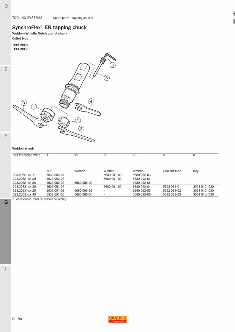
G 184
TOOLING SYSTEMS Spare parts - Tapping chucks
E
F
G
J
D
G
RO
T - E
NG
TOOLING SYSTEMS Spare parts - Tapping chucks
SynchroFlex® ER tapping chuckWeldon/Whistle Notch combi shankCollet type
Weldon shank
393.2062393.2063
393.2062/393.2063 1 21) 31) 41) 5 6
Nut Wrench Wrench Wrench Coolant tube Key 393.2062 -xx 11 5533 050-07 - 5680 091-03 5680 092-03 - -393.2062 -xx 20 5533 050-08 - 5680 091-02 5680 092-04 - -393.2062 -xx 25 5533 050-02 5680 096-02 - 5680 092-05 - -393.2063 -xx 20 5533 051-02 - 5680 091-02 5680 092-04 5692 031-01 3021 010- 030393.2063 -xx 25 5533 051-03 5680 096-02 - 5680 092-05 5692 031-02 3021 010- 030393.2063 -xx 40 5533 051-05 5680 096-04 - 5680 092-06 5692 031-03 3021 010- 0301) Accessories, must be ordered separately
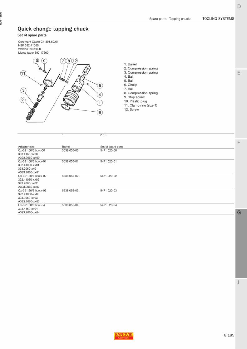
E
G 185
F
G
J
D
G
Spare parts - Tapping chucks TOOLING SYSTEMS
RO
T -
EN
G
TOOLING SYSTEMS Spare parts - Tapping chucks
Quick change tapping chuckSet of spare parts
Coromant Capto Cx-391.60/61HSK 392.41060Weldon 393.2060Morse taper 392.17660
1 2-12
Adaptor size Barrel Set of spare partsCx-391.60/61xxx-00 5638 055-00 5471 020-00393.4160-xx00A393.2060-xx00Cx-391.60/61xxxx-01 5638 055-01 5471 020-01392.41060-xx01393.2060-xx01A393.2060-xx01Cx-391.60/61xxxx-02 5638 055-02 5471 020-02392.41060-xx02393.2060-xx02A393.2060-xx02Cx-391.60/61xxxx-03 5638 055-03 5471 020-03392.41060-xx03393.2060-xx03A393.2060-xx03Cx-391.60/61xxx-04 5638 055-04 5471 020-04393.4160-xx04A393.2060-xx04
1. Barrel2. Compression spring3. Compression spring4. Ball5. Ball6. Circlip7. Ball8. Compression spring9. Stop screw10. Plastic plug11. Clamp ring (size 1)12. Screw
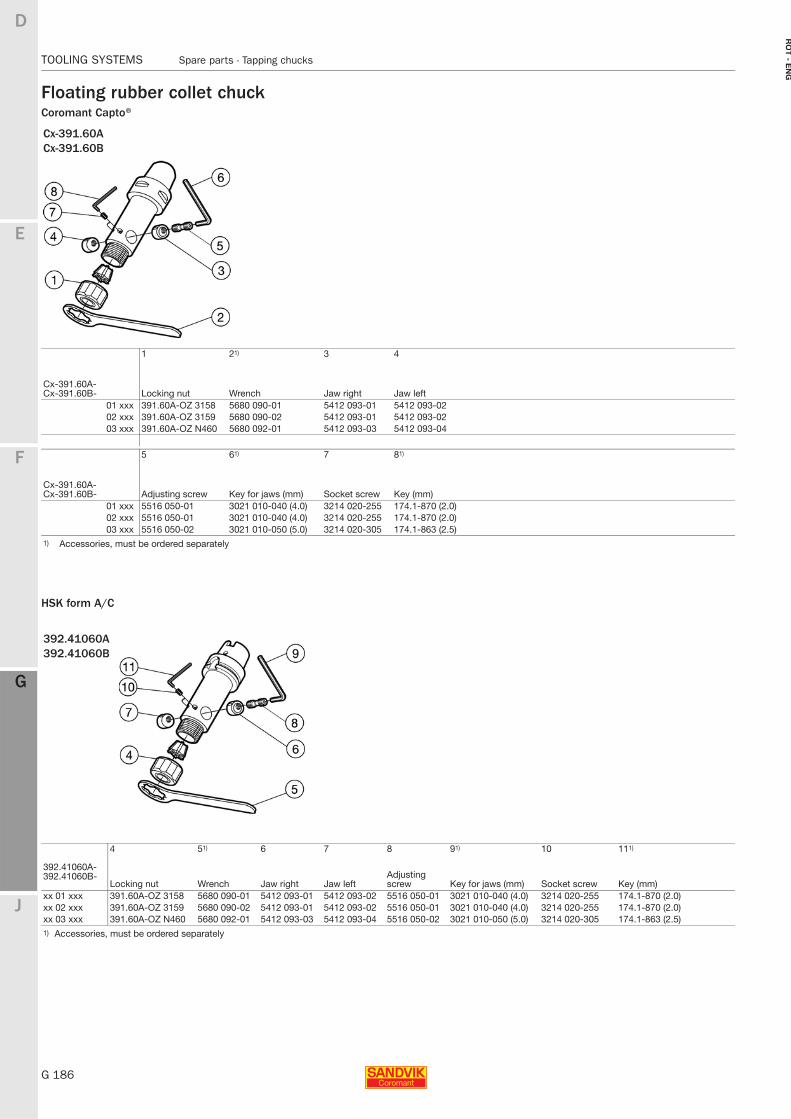
G 186
TOOLING SYSTEMS Spare parts - Tapping chucks
E
F
G
J
D
G
RO
T - E
NG
TOOLING SYSTEMS Spare parts - Tapping chucks
Floating rubber collet chuckCoromant Capto®
HSK form A/C
Cx-391.60ACx-391.60B
1 21) 3 4
Cx-391.60A-Cx-391.60B- Locking nut Wrench Jaw right Jaw left
01 xxx 391.60A-OZ 3158 5680 090-01 5412 093-01 5412 093-0202 xxx 391.60A-OZ 3159 5680 090-02 5412 093-01 5412 093-0203 xxx 391.60A-OZ N460 5680 092-01 5412 093-03 5412 093-04
5 61) 7 81)
Cx-391.60A-Cx-391.60B- Adjusting screw Key for jaws (mm) Socket screw Key (mm)
01 xxx 5516 050-01 3021 010-040 (4.0) 3214 020-255 174.1-870 (2.0)02 xxx 5516 050-01 3021 010-040 (4.0) 3214 020-255 174.1-870 (2.0)03 xxx 5516 050-02 3021 010-050 (5.0) 3214 020-305 174.1-863 (2.5)
1) Accessories, must be ordered separately
392.41060A392.41060B
4 51) 6 7 8 91) 10 111)
392.41060A-392.41060B-
Locking nut Wrench Jaw right Jaw leftAdjusting screw Key for jaws (mm) Socket screw Key (mm)
xx 01 xxx 391.60A-OZ 3158 5680 090-01 5412 093-01 5412 093-02 5516 050-01 3021 010-040 (4.0) 3214 020-255 174.1-870 (2.0)xx 02 xxx 391.60A-OZ 3159 5680 090-02 5412 093-01 5412 093-02 5516 050-01 3021 010-040 (4.0) 3214 020-255 174.1-870 (2.0)xx 03 xxx 391.60A-OZ N460 5680 092-01 5412 093-03 5412 093-04 5516 050-02 3021 010-050 (5.0) 3214 020-305 174.1-863 (2.5)1) Accessories, must be ordered separately
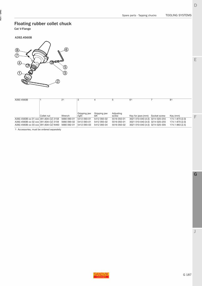
E
G 187
F
G
J
D
G
Spare parts - Tapping chucks TOOLING SYSTEMS
RO
T -
EN
G
TOOLING SYSTEMS Spare parts - Tapping chucks
Floating rubber collet chuckCat V-Flange
A392.4560B
A392.4560B 1 21) 3 4 5 61) 7 81)
Collet nut WrenchGripping jaw right
Gripping jaw left
Adjusting screw Key for jaws (mm) Socket screw Key (mm)
A392.4560B-xx 01 xxx 391.60A-OZ 3158 5680 090-01 5412 093-01 5412 093-02 5516 050-01 3021 010-040 (4.0) 3214 020-255 174.1-870 (2.0)A392.4560B-xx 02 xxx 391.60A-OZ 3159 5680 090-02 5412 093-01 5412 093-02 5516 050-01 3021 010-040 (4.0) 3214 020-255 174.1-870 (2.0)A392.4560B-xx 03 xxx 391.60A-OZ N460 5680 092-01 5412 093-03 5412 093-04 5516 050-02 3021 010-040 (4.0) 3214 020-305 174.1-863 (2.5)
1) Accessories, must be ordered separately