Embed Size (px)
Citation preview

CLINICAL ORTHOPAEDICS AND RELATED RESEARCH Number 331, pp 35-46 0 1996 Lippincott-Raven Publishers
Rotational Landmarks and Sizing of the Distal Femur in
Total Knee Arthroplasty Pascal L. Poilvache, MD*; John N. Insall, MD**; Giles R. Scuderi, MD**;
and David E. Font-Rodriguez, MD**
In 100 knees undergoing a total replacement, the angles between the tangent line of the poste- rior condylar surfaces, the anteroposterior axis as described by Whiteside, the transepicondy- lar line, and the trochlear line were measured. Also measured were the sulcus angle, the trans- epicondylar width, the height of the condyles, and the thickness of the various cuts. Radio- logic measurements made were: the mechani- cal angle, the hip center-femoral shaft angle, the transcondylar angle, and the tibial pla- teau-tibia1 shaft angle. The mean values of these measurements were calculated, and com- parisons were made according to gender and the mechanical axis using the Student's t test. Correlations between the various measure- ments were calculated. The transepicondylar axis was found to be a reliable landmark to properly rotate the femoral component, and was easier to locate at surgery than the antero- posterior axis. In trochlear dysplasia and in some valgus knees, relying on the anteroposte-
From the *Department of Orthopaedics, Saint-Luc Uni- versity Hospital, University of Louvain, Brussels, Bel- gium; and **Insall Scott Kelly Institute for Or- thopaedics and Sports Medicine Beth Israel Medical Center, North Division, New York, NY. Reprint requests to John N. Insall, MD, Insall Scott Kelly Institute for Orthopaedics and Sports Medicine Beth Israel Medical Center, North Division, 170 East End Avenue, New York, NY 101 28.
rior axis can induce an excessive external rota- tion of the femoral component, and the oppo- site can happen in some varus knees. The ante- rior extent of the condyles is highly variable in arthritic knees, and cannot be used to orient the prosthesis. The ratio between the transepi- condylar width and the height of the condyles is constant, but some narrow femora could re- quire narrower implants to avoid medial-lat- era1 overhang of the femoral component.
Proper rotational alignment of the femoral component is critical for the outcome of total knee arthroplasty.l,5,'6.23,31,36 The most fre- quent reasons for reoperation with current condylar prostheses, other than sepsis, relate to the patellofemoral j0int.4~30~35,37,38
Malrotation of the femoral component on the femur may lead to patellofemoral dislo- cation or ~ubluxation,2.3.l7.31,3~,35 to wear or loosening of the patellar ~omponen t ,3 J5 .~~ .~~ or to fractures of the patella.15.17 Internal ro- tation of the femoral component on the fe- mur moves the groove portion of the femoral component relatively medially, making it more difficult for the relatively laterally placed patella to be captured by the patello- femoral groove.1,15,23,27,31.35,36,39 Malrotation of the femoral component may also induce a torsional stress on the tibial component that could lead to wear or loosening.13
35

36 Poilvache et al Clinical Orthopaedics
and Related Research
The orientation for the femoral compo- nent rotation in many instrumentation sys- tems has been set by equal resection of the posterior femoral ~ondyles.21~27 Insall23 and
at times, unequal amounts should be resected off the posterior femoral condyles to obtain ligamentous balance in flexion and to en- hance patellar tracking.
Insall23 and Scuderi and Insa lP recom- mended placing a tensor in the knee in flex- ion and rotating the femoral cutting block so that the posterior edge of the cutting block is parallel to the top of the tibia. This method requires that the tibia be cut first, subsequent to which the distal femur is cut to achieve a correct balance in extension. Next, the femoral cutting block can be properly rotated to obtain a rectangular flexion gap. It may be easier, and more reproducible, to rely on an anatomic landmark to obtain a proper rota- tional alignment of the femoral component.
Arima et a12 recently suggested that the anteroposterior (AP) axis of the distal femur was an easy and reliable landmark for rota- tional alignment of the femoral component, especially in the valgus knee.
For various theoretical reasons that will be briefly discussed, and on the basis of the senior author's clinical experience (JI), the authors thought that the transepicondylar axis was a sound landmark to ensure correct femoral rotational alignment.
Several studies concerning the anatomy and functional axes of the femur have previ- ously been made on normal anatomic speci-
thors' knowledge, none have been done on arthritic knees at surgery. Those anatomic studies generally ignored the valgus or varus angle of the knee, and were made on bones cleaned from all soft tissues. For those rea- sons, it seemed useful to perform rotational measurements at surgery, in the course of a total knee replacement. Added to those angu- lar measurements were several radiologic measurements and also some linear measure- ments related to the sizing of the distal femur.
othe~~1.2.3.5.9.10.15.31.36.3Y.41 recommended that,
men femo~a2.3.14.26.28.29.40.44 but, to the au-
MATERIALS AND METHODS
A consecutive series of 100 knees undergoing a total knee arthroplasty was studied. The series in- cluded 40 bilateral and 60 unilateral total knee arthroplasties, in 80 patients. Thirty-seven were men (46 knees) and 43 were women (54 knees). The mean age of the group was 67 years (range, 36-84 years). Seventy-nine patients had os- teoarthritis and 1 had rheumatoid arthritis. Six pa- tients (7 knees) had had a previous high tibia1 osteotomy, 1 had had a patellectomy, and 1 had had an anterior cruciate ligament replacement.
The mean alignment or mechanical angle (Fig I ) , defined as the angle between the mechanical axis of the femur and the mechanical axis of the tibia,h,YJX,?J,-'l was 7.5" varus. Eleven knees were in valgus (alignment < -3"), and 89 were neutral or in varus (alignment > -3").
Eight of the 11 valgus knees had a lateral reti- nacular release, whereas only 15 of the 89 neutral or varus knees needed a lateral retinacular re- lease. The tracking of the patella was checked us- ing the no thumb technique, and no maltracking was accepted.
A line was drawn on the distal femoral surface (Fig 2 ) , using a caliper positioned on the most prominent aspect of the lateral and medial epi- condyles. This epicondylar line parallels the clin- ical epicondylar axis, defined by Berger et al,' connecting the lateral epicondylar prominence and the most prominent point on the medial epi- condyle. Locating those 2 prominences seemed easy at surgery, and there was little variation be- tween the various surgeons involved in the opera- tions about the orientation of this line. On the contrary, the authors were unable to locate the medial sulcus of the medial epicondyle, used by Berger et al-' on anatomic specimens to define the surgical epicondylar axis.
A second line was drawn on the distal femoral surface, using a guide applied on the posterior condyles. This line paralleled the posterior condylar line. The third line was drawn through the deepest part of the patellar groove anteriorly and the center of the intercondylar notch posteri- orly, corresponding to the AP axis, as defined by Arima et a1.2 The angles between those 3 lines were measured using a goniometer. Care was taken to position the goniometer in a plane per- pendicular to the mechanical axis of the femur. The angle between the epicondylar line and the

Number 331 October, 1996 Landmarks and Sizing of the Distal Femur 37
Fig 1. Diagram of the radiologic measure- ments. a = mechanical axis of the femur-me- chanical axis of the tibia angle; p = mechanical axis of the femur-anatomic axis of the femur angle; 6 = mechanical axis of the femur-distal condylar line angle; and 6' = tibia1 plateau-tib- ial shaft angle.
posterior condylar line was double checked by measuring the distance between the 2 lines in 2 points 5 cm distant, and using a simple trigono- metric formula, as described previously by Man- tas et a1.28
A metallic plate was placed on the trochlea, to figure a line connecting the most anterior projec- tions of the lateral and medial femoral condyles. The angle between this line and the epicondylar line was measured and was called the trochleo- epicondylar angle. The sulcus angle was mea-
Condylzv Lane
Fig 2. Diagram of the axial view of the distal fe- mur. A and B = the most anterior projections of the lateral and medial femoral condyles; C and D = the most posterior projections of the lateral and medial femoral condyles; E and F = the most prominent points of the lateral and medial epicondyles; G = the deepest part of the trochlar groove; H = the center of the inter- condylar notch; AB = trochlear line; EF = epi- condylar line; CD = posterior condylar line; GH = anterior-posterior line; AGB = 0 = sulcus an- gle; E = AP line-epicondylar line angle; K = AP line-posterior condylar line angle; 0 = epi- condylar line-posterior condylar line angle; z = trochlear line-epicondylar line angle; H3 = height of the lateral condyle; H4 = height of the medial condyle; al = anterior lateral cut; pl = posterior lateral cut; am = anterior medial cut; and pm = posterior medial cut.
sured using specially designed metallic tem- plates. The transepicondylar width, defined as the distance from the medial to the lateral epi- condyle, and the AP dimension of the lateral and the medial condyles were also recorded, as well as the thickness of the various cuts (anterior lat- eral, anterior medial, posterior lateral, posterior medial, distal lateral, and distal medial).
The radiologic measurements, performed on standing long leg AP radiographs, included (Fig 1): the alignment of the lower limb; the hip cen- tcr-femoral shaft angle, defined as the angle be- tween the mechanical and the anatomic axes of the femur; the transcondylar angle, defined as the angle between the tangent line of the condyles and the mechanical axis of the femur; and the tib- ial plateau-tibia1 shaft angle, defined as the angle
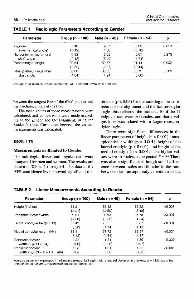
38 Poilvache et al Clinical Orthopaedics and Related Research
TABLE 1. Radiologic Parameters According to Gender
Parameter Group (n = 100) Male (n = 46) Female (n = 54) P
Alignment 7.46 (mechanical angle) [7.42]
Hip center minus femoral 6.33 shaft angle [2.42]
Transcondylar angle 90.64 [2.82]
Tibia1 plateau minus tibial 86.08 shaft angle [4.04]
9.37 [4.86] 6.63
[3.00] 89.67 [2.97]
85.33 [4.24]
5.83 0.013 [8.78] 6.07 0.273
[1.78] 91.44 0.002 [2.44] 86.72 0.089 [3.80]
Average values are expressed in degrees, with standard deviation in brackets
between the tangent line of the tibial plateau and the mechanical axis of the tibia.
The mean values of those measurements were calculated, and comparisons were made accord- ing to the gender and the alignment, using the Student’s t test. Correlation between the various measurements was calculated.
RESULTS
Measurements as Related to Gender The radiologic, linear, and angular data were compared for men and women. The results are shown in Tables 1 through 4. The data at the 95% confidence level showed significant dif-
ference (p < 0.05) for the radiologic measure- ments of the alignment and the transcondylar angle: this reflected the fact that 10 of the 11 valgus knees were in females, and that a val- gus knee was related with a larger transcon- dylar angle.
There were significant differences in the linear parameters of height (p < 0.001), trans- epicondylar width (p < 0.001), height of the lateral condyle (p < O.OOl), and height of the medial condyle (p < 0.001). The higher val- ues were in males, as expected.29.40.44 There was also a significant although small differ- ence between males and females in the ratio between the transepicondylar width and the
TABLE 2. Linear Measurements According to Gender
Parameter Group (n = 100) Male (n = 46) Female (n = 54) P
Height (inches)
Transepicondylar width
Lateral condylar height (H3)
Medial condylar height (H4)
Transepicondylar
Transepicondylar width x 2/(H3 + H4)
width x 2/(H3 - al + H4 - am)
66.2 [4.27] 90.91 [7.30] 69.42 [5.50] 68.4 [5.48] 1.32
[0.06] 1.58
[0.08]
69.12
96.93 t3.501
[5.25] 73 [4.74] 71.72 [4.54] 1.34
[0.05] 1.61
[0.68]
63.82 <0.001 [3.18] 85.78 <0.001 [4.24] 66.37 <0.001 [4.12] 65.57 <0.001 [4.57] 1.30 0.002
[0.07] 1.55 <0.001
[0.08]
Average values are expressed in millimeters (except for height), with standard deviation in brackets. al = thickness of the anterior lateral cut; am = thickness of the anterior medial cut.

Number 331 October, 1996 Landmarks and Sizing of the Distal Femur 39
TABLE 3. Angular Measurements According to Gender
Parameter Group Male Female
(n = 100) (n = 46) (n = 54) P
Anteroposterior line minus epicondylar line angle
Anteroposterior line minus posterior condylar line angle
Epicondylar line minus posterior condylar line angle
Trochleo-epicondylar angle
Sulcus angle
90.33 [2.44] 86.92 [2.71] 3.60
[2.02] 4.95
[2.15]
[6.96] 139.5
91.2 [2.15] 88.07 [2.34] 3.58
[2.16] 4.40
[2.14] 139.67
[5.48]
89.59 0.001 [2.45] 85.94 <0.001 [2.64] 3.62 0.936 [1.93] 5.38 0.028
[2.07] 139.42 0.857
[5.48]
Average values are expressed in degrees, with standard deviation in brackets
mean height of the condyles (p = 0.002), suggesting that females had narrower femurs than males. This difference was even more significant when substracting the anterior extent of the trochlea (anterior cuts) to the height of the condyles (p = 0.0002). When considering this ratio in individual patients, it seemed that the range was relatively wide (1.40-1.89), with again the narrowest femurs
in females and the broadest in males. The relatively broadest femora were found in the tallest patients (p = 0.006).
Regarding the rotatory measurements, sig- nificant differences between the genders were found for the angles between the AP line and the posterior condylar line (p < 0.001) and be- tween the AP line and the epicondylar line (p = 0.028), but not for the angle between the
TABLE 4. Thickness of the Various Cuts According to Gender
Parameter Group Male Female
(n = 100) (n = 46) (n = 54) P
Anterior lateral
Anterior medial
Posterior lateral
Posterior medial
Distal lateral
Distal medial
Anterior lateral minus anterior
Posterior lateral minus posterior
Distal lateral minus distal medial
medial
medial
12.94 [2.60] 9.73
[2.65] 7.1 1
[ 1.931 9.82
[ 1.861 10.09 [2.66] 9.46 [1.79] 3.21 [2.27]
-2.71 [2.11] 0.62
[2.75]
13.74 [2.76] 10.63 [2.48] 7.54
[ 1.961 10.00 [ 1.871 11.35 [ 1.831 9.56
[2.03] 3.11 [2.32]
[2.17] 1.78
[ 1.901
-2.48
12.26 [2.26] 8.96
[2.56] 6.74
[1.84] 9.67 [1.84] 9.02
[2.79] 9.38
[ 1.581 3.30
[2.37]
[2.05] -2.93
-0.36 [2.98]
0.005
0.001
0.039
0.374
<0.001
0.616
0.683
0.272
<0.001
Average values are expressed in millimeters with standard deviation in brackets

40 Poilvache et al Clinical Orthopaedics and Related Research
epicondylar line and the posterior condylar line. This suggests that the trochlear groove is angled somewhat externally relative to the epicondylar line in females, and somewhat medially in males. The predominance of fe- males in the valgus group does not entirely account for this difference.
Significant differences between the gen- ders were found for the anterior lateral cut (p = 0.005), the anterior medial cut (p = 0.001), the posterior lateral cut (p = 0.0039), the dis- tal lateral cut (p c 0.001), and for the differ- ence between the distal lateral and the distal medial cut (p < 0.001). The anterior extent of the trochlea was smaller in females, but this difference can be explained by the smaller size of the femurs. The difference for the posterior lateral and distal lateral cuts can be explained by the predominance of females in the valgus group.
Measurements as Related to Preoperative Deformity The data for patients with varus and valgus alignment are shown in Tables 5 through 8. There were significant differences for the transcondylar angle (p = 0.001), the tibial plateau-tibia1 shaft angle (p = 0.001), and for the hip center-femoral shaft angle (p = 0.001). There was a slightly significant difference for the transepicondylar width (p = 0.048), re- flecting again the female predominance in the valgus group. When the femoral angular
measurements were evaluated, there were significant differences for the AP line-epi- condylar line angle (p = 0.047) and for the AP line-posterior condylar line angle (p = 0.001), but not for the epicondylar line-pos- terior condylar line angle (p = 0.15).
The epicondylar line was externally ro- tated relative to the posterior condylar line by 3.51" 2 2.03" in varus or neutral knees, and by 4.41" f 1.83" in valgus knees (differ- ence 0.9"). If the rotation of the femoral component was set according to the AP line, the amount of external rotation would be 2.73" k 2.57" in varus or neutral knees, and 5.91" k 2.21" in valgus knees (difference 3.18"). There were significant differences for the distal lateral cut (p < 0.001), for the dif- ference between the posterior lateral and posterior medial cuts (p = 0.023), and for the difference between the anterior lateral and the anterior medial cuts (p = 0.022). The pos- terior lateral cut was 4.36 f 2.25 mm thinner than the posterior medial cut in valgus knees, and 2.51 k 2.01 in varus or neutral knees. The trochleo-epicondylar angle had a mean value of 4.95" k 2.15" and was slightly higher in valgus knees (5.40" f 2.32") than in varus or neutral knees (4.89" f 2.13") but this difference was not significant.
Similar t tests were done on the paired knees from 40 bilateral total knee replace- ments, and they revealed no significant dif- ference for any measurement. Wilcoxon
TABLE 5. Radiologic Parameters According to Alignment
Varus-Neutral Valgus Parameter (n = 89) (n = 11) P
Alignment 9.51 (mechanical angle) [4.67]
Hip center minus femoral 6.47 shaft angle [2.51]
Transcondylar angle 90.31 [2.72]
Tibia1 plateau minus tibial 85.42 shaft angle [3.66]
-9.09 <0.001 [3.96] 5.18 0.001
[0.87] 93.27 0.001 [2.24] 91.45 <0.001 [2.91]
Average values are expressed in degrees, with standard deviation in brackets

Number 331 October. 1996 Landmarks and Sizing of the Distal Femur 41
TABLE 6. Linear Measurements According to Alignment
Varus-Neutral Valgus Parameter (n = 89) (n = 11) P
~
Transepicondylar width 91.31 [7.46]
Lateral condylar height (H3) 69.64 [5.46]
Medial condylar height (H4) 68.45 [5.45]
Transepicondylar width 1.58 x2 / (H3-a l+H4-am) [o.oai]
87.64 0.048 [5.06]
[5.80] 68.00 0.816 [5.98] 1.55 0.373
67.64 0.298
[0.11]
Average values are expressed in millimeters, with standard deviation in brackets. al = thickness of the anterior lateral cut; am = thickness of the anterior medial cut.
signed ranks tests confirmed those t tests. There was a significant association between a lateral retinacular release (excluding the combined valgus and patellar releases in valgus knees), and a large sulcus angle (p = 0.029), a small AP line-posterior condylar line angle (p = 0.01), and a small difference in the anterior lateral and anterior medial cuts (p = 0.02). The Table 9 summarizes the corre- lations performed. There was a strong corre- lation between the alignment and the AP line-posterior condylar line angle (p = O.OOl), the hip center-femoral shaft angle (p = 0.0 1 S), the transcondylar angle (p < 0.001), and the tibia1 shaft-tibia1 plateau angle (p < 0.001). There was also a correlation between the
alignment and the angle between the AP line and the epicondylar axis, suggesting again that the amount of external rotation induced by the AP line varied more widely from varus knees to valgus knees than the one induced by the epicondylar line. The AP line-epi- condylar line angle, the AP line-posterior condylar line angle, and the epicondylar line- posterior condylar line angle were also strongly correlated to each other.
DISCUSSION
The accuracy of the measurements done at surgery, using a caliper, a goniometer, a ruler, and metallic templates is by no doubt
TABLE 7. Angular Measurements According to Alignment
Varus-Neutral Valgus Parameter (n = 89) (n = 11) P
Anteroposterior line 90.53 epicondylar line angle [2.36]
Anteroposterior line minus 87.27 posterior condylar line angle [2.57]
Epicondylar line minus 3.51 posterior condylar line angle [2.03]
[2.13] Sulcus angle 139.67
[7.08]
Trochleo-epicondylar angle 4.89
88.73 0.047 [2.57] 84.09 0.001
4.41 0.15 [1.83] 5.40 0.524 [2.52]
138.40 0.550 [6.06]
[2.21]
Average values are expressed in degrees, with standard deviation in brackets

42 Poilvache et al Clinical Orthopaedics
and Related Research
TABLE 8. Thickness of the Various Cuts According to Alignment
Varus-Neutral Valgus Parameter (n = 89) (n = 11) P
Anterior lateral 12.90 13.27 0.576
Anterior medial 9.82 9.00 0.219
Posterior lateral 7.30 5.54 0.059
Posterior medial 9.81 9.91 0.895
Distal lateral 10.62 5.82 < 0.001
Distal medial 9.48 9.36 0.806
Anterior lateral minus 3.08 4.27 0.022 anterior medial [2.33] [ 1.351 0.023
Posterior lateral minus -2.51 -4.36 posterior medial [2.01] [2.25]
Distal lateral minus distal 1.14 -3.54 < 0,001 medial [2.23] [3.04]
[2.67] [ 1.951
[2.72] [ 1.901
[ 1.741 [2.70]
[ 1.801 [2.39]
[2.08] [3.03]
[ 1.851 [1.36]
Average values are expressed in millimeters. with standard deviation in brackets
lower than the accuracy of an anatomic
over, there is no other way to check the re- producibility of the measurements than to ask to various surgeons to perform them on the same patient. Although there was usu- ally an agreement among the observers for the measurements done, this is not a true sci- entific test. The results of this study should therefore be interpreted cautiously.
The radiologic measurements confirmed the already known fact7-19-22 that there is a medial slope of the condyles in valgus knees, and a medial slope of the tibial plateau in varus and neutral knees. The hip center-femoral shaft angle was slightly nar- rower in valgus knees than in varus knees. This difference seemed significant, although this angle can be affected by rotation of the f e m ~ r . 2 ~ The linear measurements showed that some females have narrower femurs than the average. This confirms the surgical finding that, in some femurs, the femoral component with the adequate AP dimension
specimen st,dy.2,3.7.14.26,28.29.40,43.444 More- may be too broad. Additional anatomic work in this field could be useful.
Rotational alignment of the femoral com- ponent affects patellar tracking, patello- femoral contact points and pressures, and varus-valgus and rotational alignment of the knee.l.24 In most normal knees, perpendicu- lar resection of the upper tibial surface re- moves more bone from the lateral surface of the tibial plateau than from the medial sur- face, because the normal upper tibia has a 3" varus slope.8.9,19.23,25,3'.32 To obtain a rectan- gular flexion gap, a larger amount of bone should be resected off the posterior femoral medial condyle than off the posterior lateral condyle.23932J9 This argument has been ex- perimentally confirmed by Anouchi et all and Rhoads et al.36 Those 2 studies showed that patellar tracking after external rotation of the femoral component came closer to re- producing that of the intact knee than any other femoral component position. Internal rotation of the femoral component produced significant changes in the patellar tracking

Number 331 October, 1996 Landmarks and Sizing of the Distal Femur 43
TABLE 9. Correlation Table
Variable 1 Variable 2 R2 P
a P 0.055 0.018 a 6 0.151 < 0.001 a 6' 0.334 < 0.001 a K 0.109 0.001 a & 0.050 0.026 a U 0.009 0.356 K E 0.568 < 0.001 K U 0.141 < 0.001 & U 0.064 0.01 1 PI - Prn K 0.170 < 0.001 PI - Prn U 0.195 < 0.001
PI - Pm dl - drn 0.099 0.001 PI - Prn & 0.01 8 0.183
Transepicondylar width Height 0.075 0.006 x' 2/(H3 - al + H4 - am)
Letters in the variables columns refer to Figures 1 and 2.
pattern that would be expected to increase the incidence of patellar dislocation in pros- thetic designs with a shallow trochlear groove, and to increase the incidence of patellar loosening, eccentric wear, and patellar fracture in a prosthesis with a high lateral ridge. Internally rotating the femoral component has also an adverse effect on knee alignment,3 due to the creation of a trapezoidal flexion gap. Nevertheless, a me- dial slope of the tibia1 plateau is not con- stantly encountered,32 and it is not clear if the femoral component has to be externally rotated in every total knee replacement,'S and which amount of external rotation has to be set.
Eckhoff and CoworkersllJ2 have shown that rotational malalignment, with axial mal- alignment should be considered a mechani- cal cause of arthrosis. There is a positive correlation between decreased rotation in the femur and increased arthrosis of the me- dial femoral-tibia1 articulation11933 and be- tween increased femoral anteversion and patellar arthrosis.1lJ2Jg.20 There is more ver- sion in the arthritic knee than in the normal knee." The durability of an arthroplasty for arthrosis may be limited if the intrinsic rota-
tional deformity of the limb is not ad-
Several methods have been proposed to establish rotational alignment of the femoral component. Insall's technique of the flexion gap consists in rotating the femoral cutting block to create a rectangular flexion gap.23.39 In this technique, the rotational alignment is dependent on the condition of the medial soft tissues. Arima et a12 proposed a tech- nique for using the AP axis of the distal fe- mur to establish rotational alignment of the femoral component in the valgus knee. They stated that a line perpendicular to the AP axis consistently was approximated at 4" ex- ternal rotation relative to the posterior condylar surfaces (3.89" k 1.77") and found that the epicondylar axis was more difficult to define, and was not as accurate (4.43" f 2.81"). The values the authors found in arthritic knees were close to those found by Arima et al, with a larger dispersion: the line perpendicular to the AP axis was at 3.08" f 2.71" of external rotation relative to the pos- terior condylar surfaces, the epicondylar line was at 3.60" f 2.02" external rotation, close to the results of previous anatomic studies,3J,28.44 and the AP axis and the epi-
dressed. 11.13,33,42

44 Poilvache et al Clinical Orthopaedics
and Related Research
condylar line were roughly perpendicular to each other (90.33" f 2.44").
The authors' opinion in arthritic knees is that the AP axis is sometimes difficult to de- fine, because of trochlear wear or to inter- condylar osteophytes. In case of severe trochlear dysplasia relying exclusively on the AP axis could induce excessive external rotation of the femoral component, as illus- trated by the wide range (19") of the angle between the AP line an the posterior condy- lar line. In some varus knees, relying on the AP line could induce an internal rotation as high as 7". On the contrary, the range of the angle between the epicondylar line and the posterior condylar line was narrow (8" from -1" to 7") and relying on the epicondylar line would not induce an internal rotation superior to 1". The range of the angle be- tween the AP line and the epicondylar axis was 14".
Kurosawa et a126 and Elias et all4 have shown that the posterior femoral condyles closely fit spheric surfaces, of average ra- dius 20 mm with a medial-lateral spacing of 46 mm. In a given knee, the radii can be slightly different for the medial and for the lateral condyle. Elias et all4 found that the femoral attachments of the medial collateral and posterior cruciate ligaments and of the lateral collateral and anterior cruciate liga- ments were in the area of the center of the medial and lateral posterior femoral circles respectively.
Yoshioka et al,44 in an anatomic specimen study of 32 normal femora, found that the mean transepicondylar line was at a right angle to the mechanical axis of the femur in the frontal plane, and that with the knee flexed to 90°, the transepicondylar line made a right angle to the long axis of the tibia as well. In this study,43,44 the posterior extent of the condyles referred to the trans- epicondylar line showed wide variations, the posterior extent of the lateral condyle being smaller than that of the medial con- dyle. The transcondylar valgus angle, or the distal extent of the condyles to transepicon-
dylar line was also variable, the distal extent of the lateral condyle being again usually smaller than that of the medial condyle.
The perpendicularity of the transepi- condylar line to the mechanical axis of the femur, and to the mechanical axis of the tibia with the knee flexed to 90", makes it a sound landmark for rotational alignment of the femoral component when resecting the proximal tibia at right angles to its mechani- cal axis. The present study confirms that this landmark can easily be used at surgery, and that it correlates well with the AP axis de- scribed by Arima et al.? The advantages of the epicondylar line as opposed to the AP axis are that it is less dependent on patello- femoral dysplasia or arthritis, that it is less variable, and that it is never significantly in- ternally rotated relative to the posterior con- dylar line. It can be used in primary total knee arthroplasty, whatever the alignment, and in revision knee replacement. Double checking the rotation by drawing the AP line and a line parallel to the epicondylar axis should ensure a proper femoral rotational alignment in most total knee replacements.
The low incidence of lateral retinacular releases (15 in 89 total knee replacements) in the group of neutral or varus knees sug- gests that customizing the amount of exter- nal rotation by using those 2 landmarks can be useful even in primary total knee replace- ment. The high incidence of lateral retinacu- lar release in the valgus group is not signifi- cant, because the patellar release is a part of the valgus release routinely performed.
The data presented here underline the im- portance of measuring the angle between the transepicondylar axis and the posterior condylar line to orient the femoral compo- nent, and suggest that some narrow femurs could require narrower femoral implants.
References
1. Anouchi YS, Whiteside LA, Kaiser AD, Milliano M T The effects of axial rotational alignment of the femoral component on knee stability and patellar tracking in total knee arthroplasty demonstrated on

Number 331 October, 1996 Landmarks and Sizing of the Distal Femur 45
2.
3 .
4.
5 .
6.
7.
8.
9.
10.
1 1 .
12.
13.
14.
15.
16.
17.
18.
autopsy specimens. Clin Orthop 287: 170-177, 1993. Arima J, Whiteside LA, McCarthy DS, White ES: Femoral rotational alignment, based on the antero- posterior axis, in total knee arthroplasty in a valgus knee. J Bone Joint Surg 77A:1331-1334, 1995. Berger RA, Rubash HE, See1 MJ, Thompson WH, Crossett LS: Determining the rotational alignment of the femoral component in total knee arthroplasty using the epicondylar axis. Clin Orthop 286:4(!-47, 1993. Berry DJ, Rand JA: Isolated patellar component re- vision of total knee arthroplasty. Clin Orthop 286: 1 10-1 15, 1993. Buechel FF: A sequential three-step lateral release for correcting fixed valgus knee deformities during total knee arthroplasty. Clin Orthop 260: 170-1 75, 1990. Chao EYS, Neluheni EVD, Hsu RWW, Paley D: Biomechanics of malalignment. Orthop Clin North Am 25379-386, 1994. Cooke TDV Letter to the Editor. J Arthroplasty 9:225, 1994. Cooke TDV, Bryant JT, Scudamore RA: Biome- chanical Factors in Alignment and Arthritic Disor- ders of the Knee. In FU FH, Hamer, CD, and Vince KG: Knee Surgery. Baltimore, Williams and Wilkins
Cooke TDV, Li J, Scudamore A: Radiographic as- sessment of bony contributions to knee deformity. Orthop Clin North Am 25:87-93, 1994. Cooke TDV, Pichora D, Siu D, Scudamore RA, Bryant J T Surgical implications of varus deformity of the knee with obliquity of joint surfaces. J Bone Joint Surg 71B560-565, 1989. Eckhoff DG: Effect of limb malrotation on malalignment and osteoarthritis. Orthop Clin North Am 25:405414,1994. Eckhoff DG, Montgomery WK, Kilcoyne RF, Stamm ER: Femoral morphometry and anterior knee pain. Clin Orthop 302:64-68, 1994. Eckhoff DG, Piatt BE, Gnadinger CA, Blaschke RC: Assessing rotational alignment in total knee arthroplasty. Clin Orthop 318:176-181, 1995. Elias SG, Freeman AR, Gokcay EI: A correlative study of the geometry and anatomy of the distal fe- mur. Clin Orthop 260:98-103, 1990. Figgie HE, Golberg VM, Figgie MP, et al: The effect of alignment of the implant on fractures of the patella after total knee arthroplasty. J Bone Joint Surg 71A: 103 1-1039, 1989. Figgie HE, Goldberg VM, Heiple KG, Moller HS, Gordon NH: The influence of tibial-patello- femoral location on function of the knee in patients with the posterior stabilized condylar - knee prosthesis. J Bone Joint Surg 68A:
Goldberg VM, Figgie HE, Inglis AE, et al: Patellar fracture type and prognosis in condylar knee arthro- plasty. Clin Orthop 236: 115-122, 1988. Harrison MM, Cooke TDV, Fisher SB, Griffin MP: Patterns of knee arthrosis and patella subluxation. Clin Orthop 309:56-63, 1994.
106 1 - 1078,1994.
1035-1040, 1986.
19. Healy WL, Wilk RM: Osteotomy in Treatment of the Arthritic Knee. In Scott WN (ed). The Knee. Vol 2. St. Louis, Mosby 1994.
20. Huberti HH, Hayes WC: Patellofemoral contact pressures: The influence of Q-angle and tend- ofemoral contact. J Bone Joint Surg 66A:715-724, 1984.
21. Hungerford DS, Krackow KA: Total joint arthro- plasty of the knee. Clin Orthop 192:23-33, 1985.
22. Insall JN: Surgery of the Knee. Ed 2. Vol 2. New York, Churchill Livingstone 1993.
23. Insall JN: Surgery of the Knee. Ed 2. Vol 2. New York, Churchill Livingstone 1993.
24. Jiang C, Insall JN: Effect of rotation on the axial alignment of the femur: Pitfalls in the use of femoral intramedullary guides in total knee arthroplasty. Clin Orthop 248:5&56, 1989.
25. Kapandji IA: The Physiology of the Joints. Ed 2. Vol 2. New York, Churchill Livingstone 74-75, 1970.
26. Kurosawa H, Walker PS, Abe S, Garg A, Hunter T: Geometry and motion of the knee for implant and orthotic design. J Biomech 18:487499, 1985.
27. Laskin RS, Rieger MA: The surgical technique for performing a total knee replacement arthroplasty. Orthop Clin North Am 20:3148, 1989.
28. Mantas JP, Bloebaum RD, Skedros JG, Hofmann AA: Implications of reference axes used for rota- tional alignment of the femoral component in pri- mary and revision knee arthroplasty. J Arthroplasty 7:531-535, 1992.
29. Mensch JS, Amstutz HC: Knee morphology as a guide to knee replacement. Clin Orthop 112:- 231-241, 1975.
30. Merkow RL, Soudry M, Insall JI: Patellar disloca- tion following total knee replacement. J Bone Joint Surg 67A:1321-1327, 1985.
3 1. Moreland JR: Mechanisms of failure in total knee arthroplasty. Clin Orthop 226:49-64, 1988.
32. Moreland JR, Bassett LW, Hanker GJ: Radiographic analysis of the axial alignment of the lower extrem- ity. J Bone Joint Surg 69A:745-749, 1987.
33. Moussa M: Rotational malalignment and femoral torsion in osteoarthritic knees with patellofemoral joint involvement. Clin Orthop 304: 176-1 83, 1994.
34. Ranawat CS: The patellofemoral joint in total condylar knee arthroplasty. Clin Orthop 205:93-99, 1986.
35. Rand JA: Patellar resurfacing in total knee arthro- plasty. Clin Orthop 260:11&117, 1990.
36. Rhoads DR, Noble PC, Reuben JD, Mahoney OM, Tullos HS: The effect of femoral component posi- tion on patellar tracking after total knee arthroplasty. Clin Orthop 260:43-5 I , 1990.
37. Rosenberg AG, Andriacchi TP, Barden R, Galante JO: Patellar component failure in cementless total knee arthroplasty. Clin Orthop 236: 106-1 14, 1988.
38. Scott WN, Rubinstein M, Scuderi G: Results after knee replacement with a posterior cruciate-substitut- ing prosthesis. J Bone Joint Surg 70A: 1163-1 173, 1988.

46 Poilvache et al Clinical Orthopaedics and Related Research
39. Scuderi CR, Insall JN: The posterior stabilized knee prosthesis. Orthop Clin North Am 20:71-78, 1989.
40. Seedhom BB, Longton EB, Wright V, Dowson D: Dimensions of the knee: Radiographic and autopsy study of sizes required for a knee prosthesis. Ann Rheum Dis 3 1-54, 1972.
4 1. Whiteside LA: Correction of bone defects in total arthroplasty of severely valgus knee. Clin Orthop 288:234-245, 1993.
42. Yagi T Tibia1 torsion in patients with medial-type osteoarthrotic knees. Clin Orthop 302:52-56, 1994.
43. Yoshioka Y, Cooke TDV Femoral anteversion: As- sessment based on function axes. J Orthop Res 5:86-Y 1, 1987.
44. Yoshioka Y, Siu D, Cooke TDV The anatomy and functional axis of the femur. J Bone Joint Surg 6YA:873-880,1987.