Embed Size (px)
Citation preview
page G
Level limit switchSeries RN 3000 / 6000Technical information / Instruction manual
Page
Safety notes / Technical support G2
---------------------------------------------------------------------------------------------------------
Introduction G3
---------------------------------------------------------------------------------------------------------
Function G4
---------------------------------------------------------------------------------------------------------
Technical data G6
---------------------------------------------------------------------------------------------------------
Approvals G14
---------------------------------------------------------------------------------------------------------
Options G15
---------------------------------------------------------------------------------------------------------
Mounting G16 ---------------------------------------------------------------------------------------------------------
Electrical installation G20
---------------------------------------------------------------------------------------------------------
Signal and alarm output G25
---------------------------------------------------------------------------------------------------------
Setting / Sensitivity G28
---------------------------------------------------------------------------------------------------------
Maintenance G29
---------------------------------------------------------------------------------------------------------
Notes for use in Hazardous Locations G30
---------------------------------------------------------------------------------------------------------
Disposal G32
Subject to technical change We assume no liability for typing errors.
All dimensions in mm (inches). Different variations than specified are possible.Please contact our technical consultants.
Table of contents
RN 3000 / 6000 c gi160914 1
Rotonivo® 1
2
3
4
5
6
7
8
9
10
11
12
page G
Level limit switchSeries RN 3000 / 6000Technical information / Instruction manual
Safety notes / Technical support
Notes
• Installation, maintenance and commissioning may be accomplished only by qualified technical personnel.• The product must be used only in the manner outlined in this instruction manual.
Special attention must be paid to warnings and notes as follows:
WARNING
Relates to a caution symbol on the product: A failure to observe the necessary precautions can result in death, serious injury and/or considerable material damage.
WARNING
Relates to a caution symbol on the product: Risk of electric shock
WARNING
A failure to observe the necessary precautions can result in death, serious injury and/or considerable material damage.
This symbol is used, when there is no corresponding caution symbol on the product.
CAUTION A failure to observe the necessary precautions can result in considerable material damage.
Safety symbols
In manual and on product
Description
CAUTION: refer to accompanying documents (manual) for details.
Earth (ground) Terminal
Protective Conductor Terminal
Technical support
Please contact your local supplier (for address see www.uwt.de). Otherwise you can contact:
UWT GmbH Tel.: 0049 (0)831 57123-0Westendstr. 5 Fax: 0049 (0)831 76879D-87488 Betzigau [email protected] www.uwt.de
Rotonivo®1
2
3
4
5
6
7
8
9
10
11
12RN 3000 / 6000 cgi1609142
1
2
3
4
5
6
7
8
9
10
11
12
page G
Level limit switchSeries RN 3000 / 6000Technical information / Instruction manual
Introduction
The ROTONIVO is an electromechanical Level limit switch and is used for level monitoring of bulk goods.
The units can be delivered with a wide range of Ex-approvals for use in Hazardous Areas.
They can be equipped for process over- and lowpressure and also for very high or low process temperatures.
Selected applications:
• building materials industry lime, styrofoam, moulding sand, etc.• food industry milk powder, flour, salt, etc.• plastics industry plastics granules etc.• timber industry• chemical industry• mechanical engineering
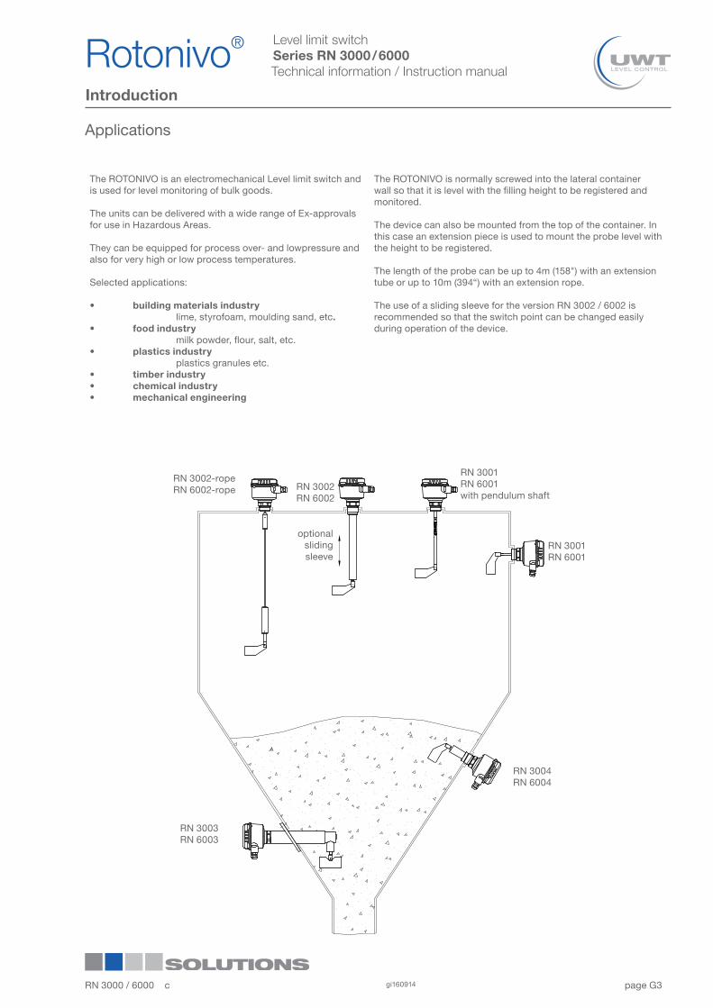
The ROTONIVO is normally screwed into the lateral container wall so that it is level with the filling height to be registered and monitored. The device can also be mounted from the top of the container. In this case an extension piece is used to mount the probe level with the height to be registered.
The length of the probe can be up to 4m (158") with an extension tube or up to 10m (394“) with an extension rope.
The use of a sliding sleeve for the version RN 3002 / 6002 is recommended so that the switch point can be changed easilyduring operation of the device.
RN 3002-ropeRN 6002-rope
optionalslidingsleeve
RN 3004RN 6004
RN 3003RN 6003
Applications
RN 3002RN 6002
RN 3001RN 6001
RN 3001RN 6001with pendulum shaft
RN 3000 / 6000 c gi160914 3
Rotonivo® 1
2
3
4
5
6
7
8
9
10
11
12
1
2
3
4
5
6
7
8
9
10
11
12
page G
Level limit switchSeries RN 3000 / 6000Technical information / Instruction manual
Function
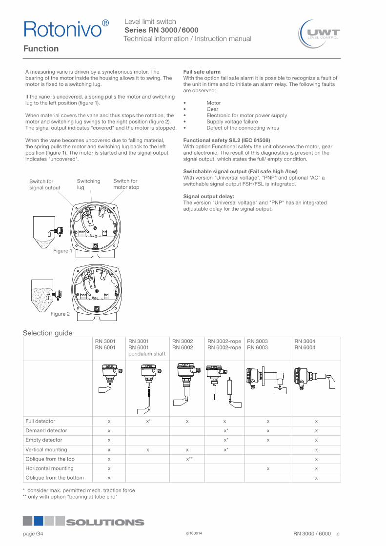
A measuring vane is driven by a synchronous motor. The bearing of the motor inside the housing allows it to swing. The motor is fixed to a switching lug.
If the vane is uncovered, a spring pulls the motor and switching lug to the left position (figure 1).
When material covers the vane and thus stops the rotation, the motor and switching lug swings to the right position (figure 2). The signal output indicates "covered" and the motor is stopped.
When the vane becomes uncovered due to falling material, the spring pulls the motor and switching lug back to the left position (figure 1). The motor is started and the signal output indicates "uncovered".
Fail safe alarmWith the option fail safe alarm it is possible to recognize a fault of the unit in time and to initiate an alarm relay. The following faults are observed:
• Motor• Gear• Electronic for motor power supply• Supply voltage failure• Defect of the connecting wires
Functional safety SIL2 (IEC 61508)With option Functional safety the unit observes the motor, gear and electronic. The result of this diagnostics is present on the signal output, which states the full/ empty condition.
Switchable signal output (Fail safe high /low)With version "Universal voltage", "PNP" and optional "AC" a switchable signal output FSH/FSL is integrated.
Signal output delay: The version "Universal voltage" and "PNP" has an integrated adjustable delay for the signal output.
Figure 1
Switch forsignal output
Switchinglug
Switch for motor stop
Figure 2
Selection guideRN 3001RN 6001
RN 3001RN 6001pendulum shaft
RN 3002RN 6002
RN 3002-ropeRN 6002-rope
RN 3003RN 6003
RN 3004RN 6004
Full detector x x* x x x x
Demand detector x x* x x
Empty detector x x* x x
Vertical mounting x x x x* x
Oblique from the top x x** x
Horizontal mounting x x x
Oblique from the bottom x x
* consider max. permitted mech. traction force** only with option "bearing at tube end"
Rotonivo®1
2
3
4
5
6
7
8
9
10
11
12RN 3000 / 6000 cgi1609144

page G
Level limit switchSeries RN 3000 / 6000Technical information / Instruction manual
Application Sealing material (1) Metal Bearing
NBR FPM (Viton) PTFE (Teflon)
Aluminium Stainless steel (2)
1.4301/ SS 304Stainless steel
Animal feed press x x x
Synthetic granules, powders x x
Salt x x x
Dust filter (temp. up to 392°F) x x
Dust filter (temp. up to 302°F) x x
Bitumen x x
Cement x x
Wood chip dryer x x
Pressure conveying vessel, 8bar x x
Sugar x x
Flour x x
Carbon black x x
Shaft sealing and metal material
(1) Delivered in version with process temperature and process pressure as following (see also option pos.17):
NBR: max 80°C and max. 0.8barFPM (Viton): max. 150°C and max. 0.8barPTFE (Teflon): max. 250°C and max. 0.8bar max. 80°C/ 150°C/ 250°C and max. 5bar/ 10bar(2) In particular cases 1.4404 (SS316L) is recommended
Function
Electronic
RN 3000
Power supplyOutput signal
SPDT (1) DPDT PNPFSH/FSL(2)
Adjustabledelay
Fail safealarm
AC version 24V or 48V or 115V or 230V AC • - - option - -
DC version 24V DC • - - - - -
DC version 24V DC PNP - - • • • -Universal voltage
24V DC / 22...230V AC • - - • • option
RN 6000
Power supplyOutput signal
SPST SPDT (1) DPDT PNPFSH/FSL(2)
Adjustabledelay
Fail safe alarm
AC version 24V or 48V or 115V or 230V AC - •
with optionFSH/FSL
- option - -option
DC version 24V DC - • - - - - optionUniversal voltage
24V DC / 22...230V AC - - • (3) - • • option
Universal voltage SIL2
24V DC / 22...230V AC • • (4) - - • • -
(1) Microswitch, with Universal voltage Relais(2) Switchable signal output (Fail safe high /low)(3) For Ex approval "Increased safety" (pos.2 C,R,S) not in combination with option Fail safe alarm(4) Additional output, not SIL conform
RN 3000 / 6000 c gi160914 5
Rotonivo® 1
2
3
4
5
6
7
8
9
10
11
12
page G
Level limit switchSeries RN 3000 / 6000Technical information / Instruction manual
Technical Data
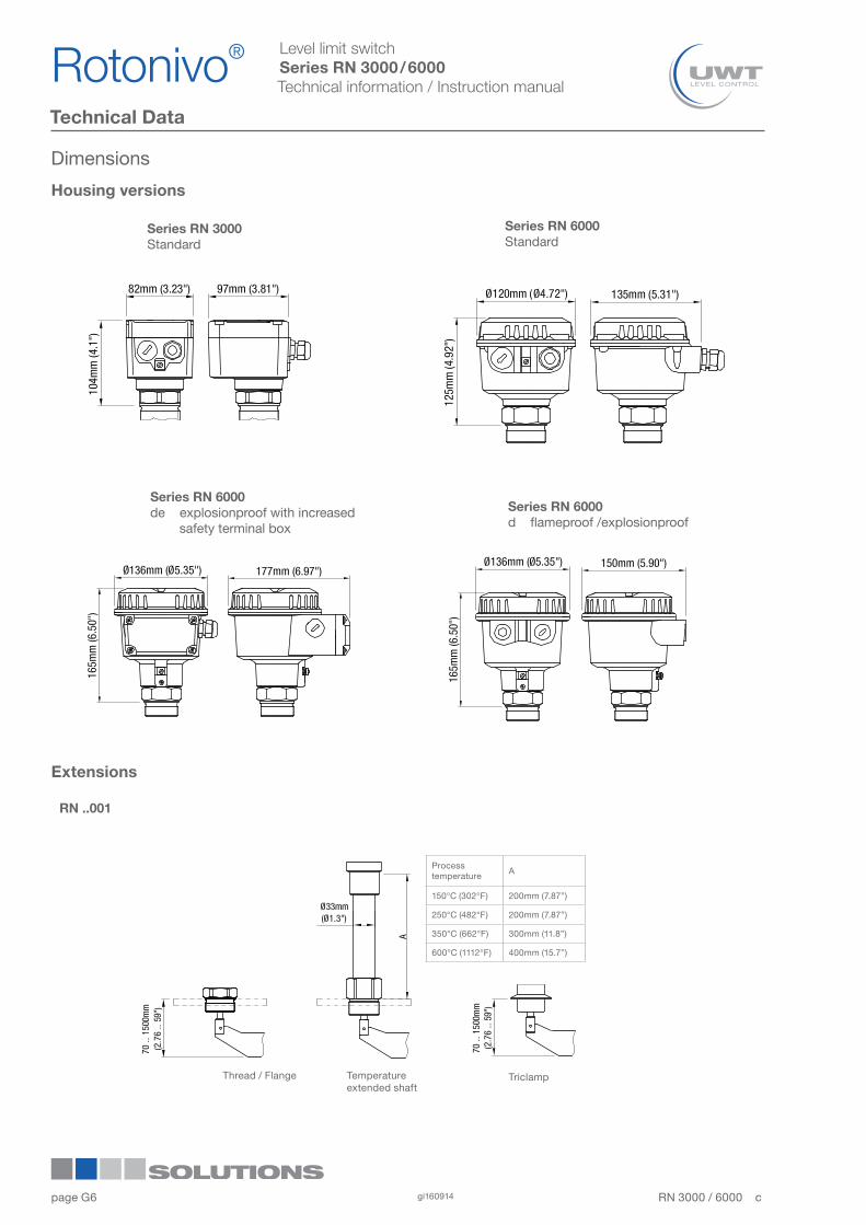
Series RN 3000Standard
Series RN 6000Standard
Series RN 6000de explosionproof with increased safety terminal box
Series RN 6000d flameproof /explosionproof
Housing versions
Extensions
RN ..001
Thread / Flange Temperature extended shaft
Processtemperature
A
150°C (302°F) 200mm (7.87”)
250°C (482°F) 200mm (7.87”)
350°C (662°F) 300mm (11.8”)
600°C (1112°F) 400mm (15.7”)
Triclamp
Dimensions
Rotonivo®1
2
3
4
5
6
7
8
9
10
11
12RN 3000 / 6000 cgi1609146
page G
Level limit switchSeries RN 3000 / 6000Technical information / Instruction manual
Technical Data
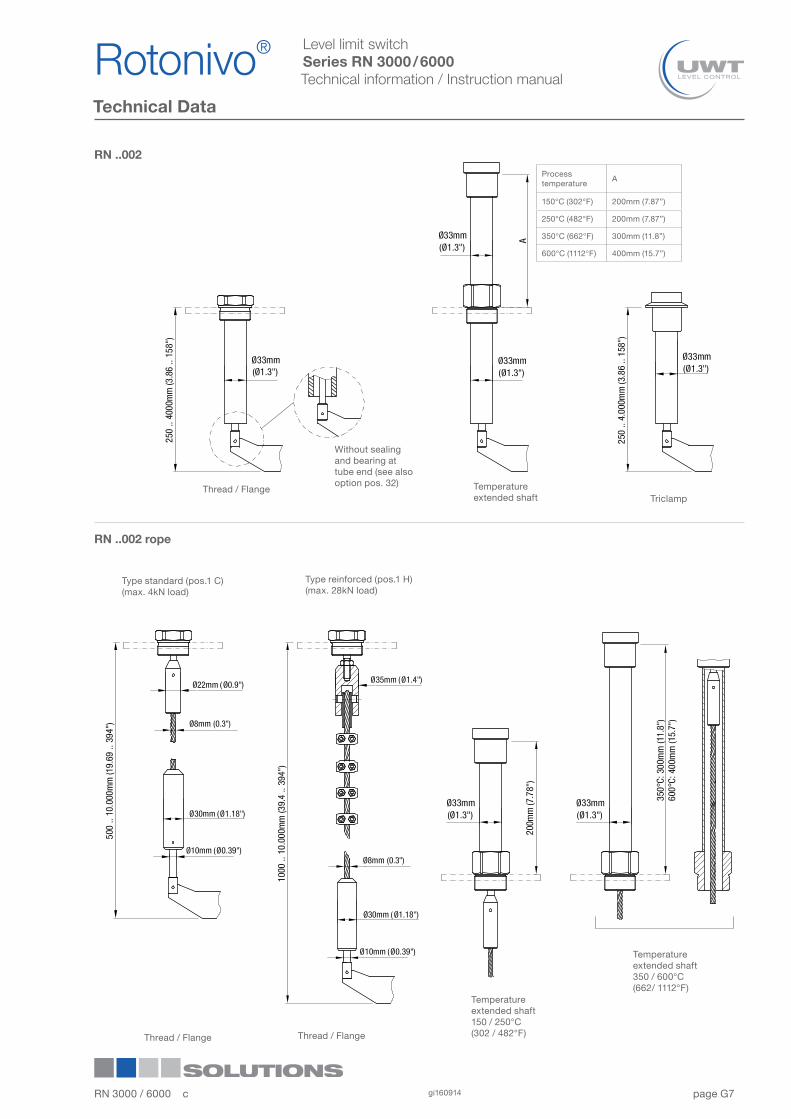
RN ..002
Without sealing and bearing at tube end (see also option pos. 32)
Thread / Flange Temperature extended shaft
RN ..002 rope
Type standard (pos.1 C)(max. 4kN load)
Type reinforced (pos.1 H)(max. 28kN load)
Thread / Flange Thread / Flange
Triclamp
Temperature extended shaft150 / 250°C(302 / 482°F)
Temperature extended shaft350 / 600°C (662/ 1112°F)
Processtemperature
A
150°C (302°F) 200mm (7.87”)
250°C (482°F) 200mm (7.87”)
350°C (662°F) 300mm (11.8”)
600°C (1112°F) 400mm (15.7”)
RN 3000 / 6000 c gi160914 7
Rotonivo® 1
2
3
4
5
6
7
8
9
10
11
12
page G
Level limit switchSeries RN 3000 / 6000Technical information / Instruction manual
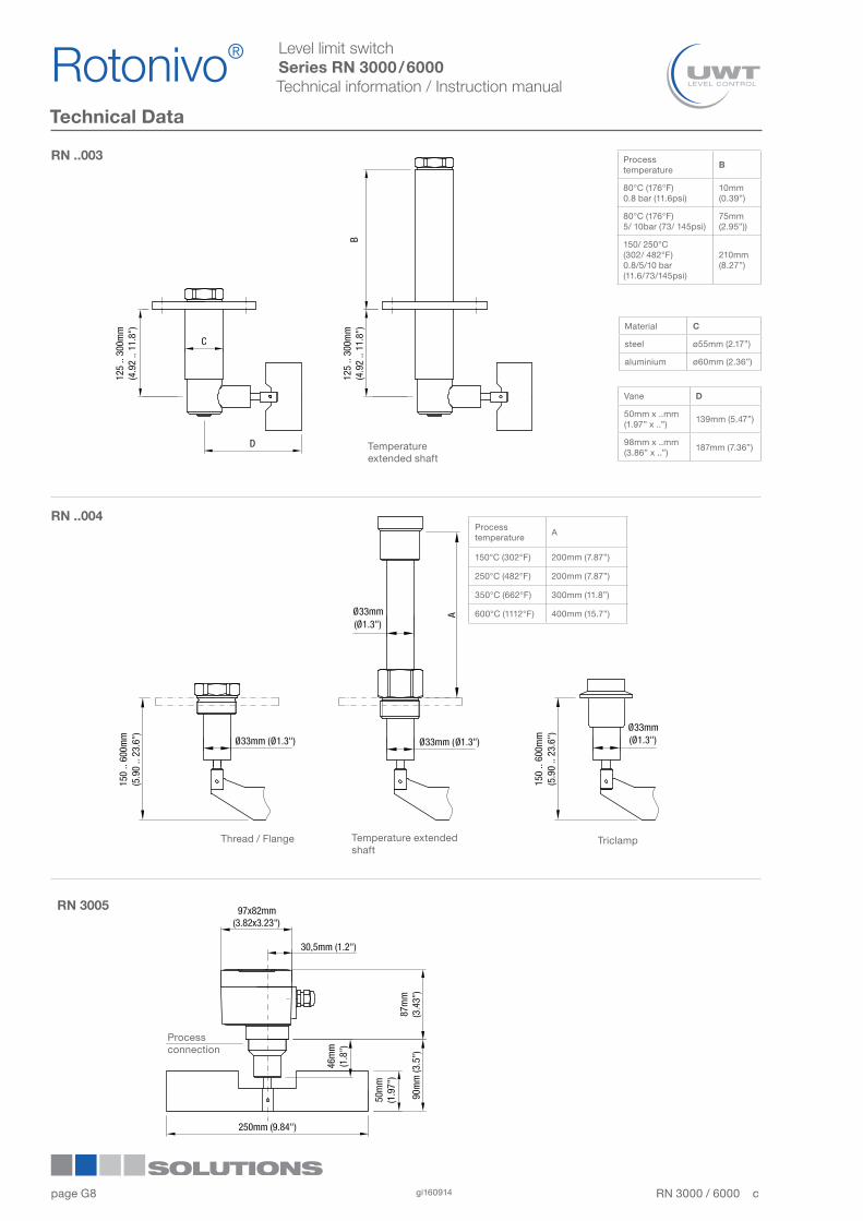
Technical Data
Processtemperature
B
80°C (176°F)0.8 bar (11.6psi)
10mm (0.39”)
80°C (176°F)5/ 10bar (73/ 145psi)
75mm (2.95”))
150/ 250°C(302/ 482°F)0.8/5/10 bar (11.6/73/145psi)
210mm (8.27”)
Material C
steel ø55mm (2.17”)
aluminium ø60mm (2.36”)
Vane D
50mm x ..mm(1.97” x ..”)
139mm (5.47”)
98mm x ..mm(3.86” x ..”)
187mm (7.36”)Temperature extended shaft
Temperature extended shaft
Thread / Flange Triclamp
Processconnection
Processtemperature
A
150°C (302°F) 200mm (7.87”)
250°C (482°F) 200mm (7.87”)
350°C (662°F) 300mm (11.8”)
600°C (1112°F) 400mm (15.7”)
Rotonivo®1
2
3
4
5
6
7
8
9
10
11
12RN 3000 / 6000 cgi1609148
RN 3005
RN ..004
RN ..003
page G
Level limit switchSeries RN 3000 / 6000Technical information / Instruction manual
Technical Data
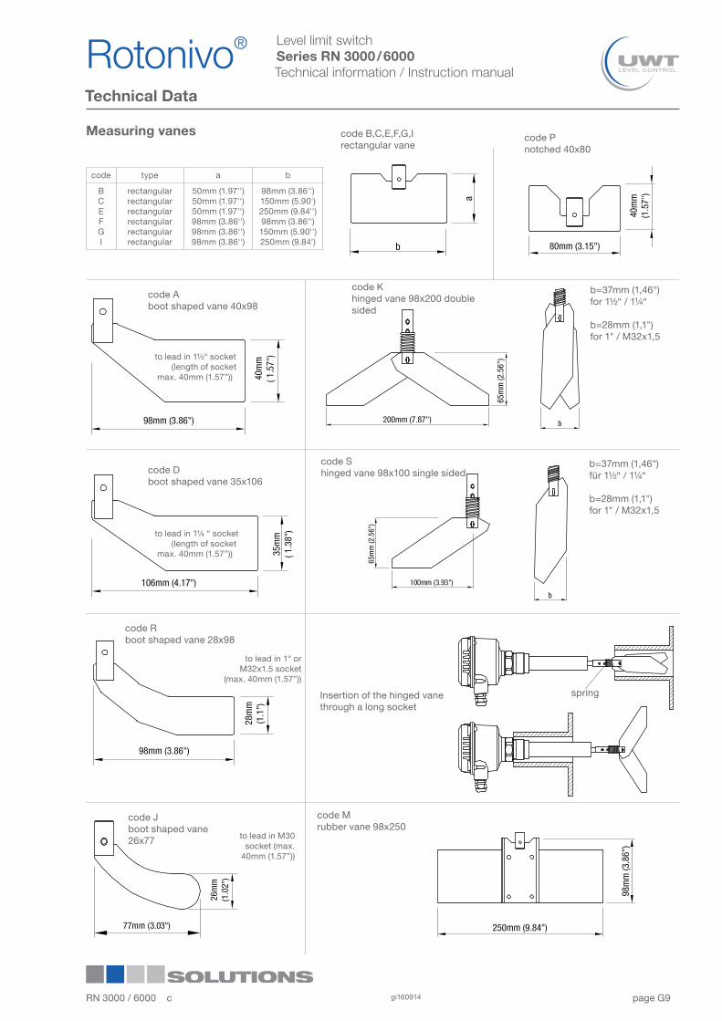
Measuring vanes
code type a b
BCEFGI
rectangularrectangularrectangularrectangularrectangularrectangular
50mm (1.97'')50mm (1.97'')50mm (1.97'')98mm (3.86'')98mm (3.86'')98mm (3.86'')
98mm (3.86'')150mm (5.90')250mm (9.84'')98mm (3.86'')150mm (5.90'')250mm (9.84')
code B,C,E,F,G,Irectangular vane
code Pnotched 40x80
code Aboot shaped vane 40x98
to lead in 1½“ socket (length of socket max. 40mm (1.57”))
to lead in 1¼ “ socket (length of socket max. 40mm (1.57”))
code Dboot shaped vane 35x106
to lead in 1“ orM32x1.5 socket
(max. 40mm (1.57”))
code Mrubber vane 98x250
Insertion of the hinged vane through a long socket
spring
code Shinged vane 98x100 single sided
code Khinged vane 98x200 double sided
code Rboot shaped vane 28x98
b=37mm (1,46")for 1½“ / 1¼“
b=28mm (1,1")for 1" / M32x1,5
b=37mm (1,46")für 1½“ / 1¼“
b=28mm (1,1")for 1" / M32x1,5
code Jboot shaped vane 26x77 to lead in M30
socket (max. 40mm (1.57”))
RN 3000 / 6000 c gi160914 9
Rotonivo® 1
2
3
4
5
6
7
8
9
10
11
12
page G
Level limit switchSeries RN 3000 / 6000Technical information / Instruction manual
Technical Data
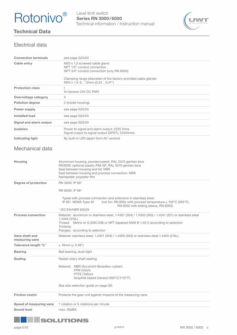
Electrical data
Connection terminals see page G23/24
Cable entry M20 x 1,5 screwed cable glandNPT 1/2“ conduit connectionNPT 3/4” conduit connection (only RN 6000)
Clamping range (diameter) of the factory provided cable glands:M20 x 1.5: 6 .. 12mm (0,24 .. 0,47")
Protection class IIII (Version 24V DC PNP)
Overvoltage category II
Pollution degree 2 (inside housing)
Power supply see page G23/24
Installed load see page G23/24
Signal and alarm output see page G23/24
Isolation Power to signal and alarm output: 2225 VrmsSignal output to signal output (DPDT): 2225Vrms
Indicating light By built-in LED (apart form AC version)
Mechanical data
Housing Aluminium housing, powdercoated, RAL 5010 gentian blueRN3000: optional plastic PA6 GF, RAL 5010 gentian blueSeal between housing and lid: NBRSeal between housing and process connection: NBRNameplate: poyester film
Degree of protection RN 3000: IP 66*
RN 6000: IP 66*
Types with process connection and extension in stainless steel: IP 66*, NEMA Type 4X (not for: RN 600x with process temperature ≥ 150°C (302°F), RN 6002 with sliding sleeve, RN 6003)* IEC/EN/NBR 60529
Process connection Material: aluminium or stainless steel, 1.4301 (304) / 1.4305 (303) / 1.4541 (321) or stainless steel 1.4404 (316L)Thread: Metric or G (DIN 228) or NPT (tapered ANSI B 1.20.1) according to selectionTriclamp Flanges: according to selection
Vane shaft and measuring vane
Material: stainless steel, 1.4301 (304) / 1.4305 (303) or stainless steel 1.4404 (316L)
Tolerance length "L“ ± 10mm (± 0.39“)
Bearing Ball bearing, dust-tight
Sealing Radial rotary shaft sealing
Material: NBR (Acrylnitril-Butadien-rubber) FPM (Viton) PTFE (Teflon) Graphite based (version 600°C/1112°F)
See also selection guide on page G5.
Friction clutch Protects the gear unit against impacts of the measuring vane
Speed of measuring vane 1 rotation or 5 rotations per minute
Sound level max. 50dBA
Rotonivo®1
2
3
4
5
6
7
8
9
10
11
12RN 3000 / 6000 cgi16091410
page G
Level limit switchSeries RN 3000 / 6000Technical information / Instruction manual
Technical Data
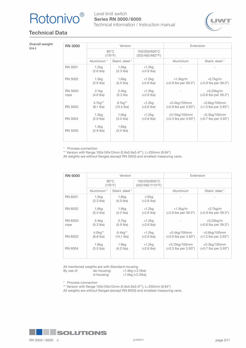
RN 3000 Version Extension
80°C (176°F)
150/250/600°C(302/482/662°F)
Aluminium * Stainl. steel * Aluminium Stainl. steel *
RN 3001
RN 3002
RN 3002-rope
RN 3003
RN 3004
RN 3005
1.2kg(2.6 lbs)
1.3kg(2.9 lbs)
2.1kg(4.6 lbs)
3.7kg**(8.1 lbs)
1.3kg(2.9 lbs)
1.3kg(2.9 lbs)
1.5kg(3.3 lbs)
1.6kg(3.5 lbs)
2.4kg(5.3 lbs
6.1kg**(13.4 lbs)
1.6kg(3.5 lbs)
1.6kg(3.5 lbs)
+1.2kg(+2.6 lbs)
+1.2kg(+2.6 lbs)
+1.2kg(+2.6 lbs)
+1.2kg(+2.6 lbs)
+1.2kg(+2.6 lbs)
-
+1.3kg/m(+2.9 lbs per 39.3“)
-
+0.4kg/100mm (+0.9 lbs per 3.93”)
+0.15kg/100mm (+0.3 lbs per 3.93”)
-
+2,7kg/m(+5.9 lbs per 39.3“)
+0,25kg/m(+0.6 lbs per 39.3“)
+0.6kg/100mm (+1.3 lbs per 3.93”)
+0.3kg/100mm (+0.7 lbs per 3.93”)
Overall weight(ca.)
* Process connection** Version with flange 150x150x12mm (5.9x5.9x0.47”), L=250mm (9.84”)All weights are without flanges (except RN 3003) and smallest measuring vane.
RN 6000 Version Extension
80°C (176°F)
150/250/600°C(302/482/1112°F)
Aluminium * Stainl. steel * Aluminium Stainl. steel *
RN 6001
RN 6002
RN 6002-rope
RN 6003
RN 6004
1.5kg(3.3 lbs)
1.6kg(3.5 lbs)
2.4kg(5.3 lbs)
4.0kg**(8.8 lbs)
1.6kg(3.5 lbs)
1.8kg(4.0 lbs)
1.9kg(4.2 lbs)
2.7kg(5.9 lbs)
6.4kg**(14.1 lbs)
1.9kg(4.2 lbs)
+12kg(+2.6 lbs)
+1.2kg(+2.6 lbs)
+1.2kg(+2.6 lbs)
+1.2kg(+2.6 lbs)
+1.2kg(+2.6 lbs)
-
+1.3kg/m(+2.9 lbs per 39.3“)
-
+0.4kg/100mm (+0.9 lbs per 3.93”)
+0.15kg/100mm (+0.3 lbs per 3.93”)
-
+2,7kg/m(+5.9 lbs per 39.3“)
+0.25kg/m(+0.6 lbs per 39.3“)
+0.6kg/100mm (+1.3 lbs per 3.93”)
+0.3kg/100mm(+0.7 lbs per 3.93”)
All mentioned weights are with Standard-housing.By use of de-housing: +1.4kg (+3.1lbs) d-housing: +1.0kg (+2.2lbs)
* Process connection** Version with flange 150x150x12mm (5.9x5.9x0.47”), L=250mm (9.84”)All weights are without flanges (except RN 6003) and smallest measuring vane.
RN 3000 / 6000 c gi160914 11
Rotonivo® 1
2
3
4
5
6
7
8
9
10
11
12
page G
Level limit switchSeries RN 3000 / 6000Technical information / Instruction manual
Technical Data
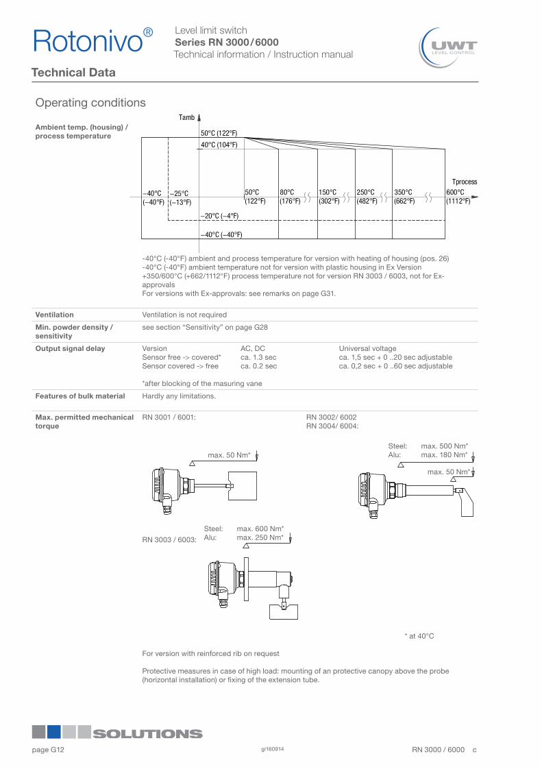
Operating conditions
Ambient temp. (housing) /process temperature
-40°C (-40°F) ambient and process temperature for version with heating of housing (pos. 26)-40°C (-40°F) ambient temperature not for version with plastic housing in Ex Version+350/600°C (+662/1112°F) process temperature not for version RN 3003 / 6003, not for Ex-approvalsFor versions with Ex-approvals: see remarks on page G31.
Ventilation Ventilation is not required
Min. powder density / sensitivity
see section “Sensitivity” on page G28
Output signal delay Version AC, DC Universal voltageSensor free -> covered* ca. 1.3 sec ca. 1,5 sec + 0 ..20 sec adjustableSensor covered -> free ca. 0.2 sec ca. 0,2 sec + 0 ..60 sec adjustable
*after blocking of the masuring vane
Features of bulk material Hardly any limitations.
Max. permitted mechanical torque
RN 3001 / 6001: RN 3002/ 6002 RN 3004/ 6004:
RN 3003 / 6003:
* at 40°C
For version with reinforced rib on request
Protective measures in case of high load: mounting of an protective canopy above the probe (horizontal installation) or fixing of the extension tube.
Steel: max. 500 Nm*Alu: max. 180 Nm*max. 50 Nm*
max. 50 Nm*
Steel: max. 600 Nm*Alu: max. 250 Nm*
Rotonivo®1
2
3
4
5
6
7
8
9
10
11
12RN 3000 / 6000 cgi16091412
page G
Level limit switchSeries RN 3000 / 6000Technical information / Instruction manual
Technische Daten
Max. tractive force RN 3001 / 6001 pendulum shaft: 400N (only applicabel as full detector)RN 3002 / 6002-rope: 4kN (type standard) 28kN (type reinforced)
Max. process pressure -0.9 .. +0.8bar (-13.1 .. 11.6psi) or -0.9 .. +5 bar (-13.1 .. 73psi) or -0.9 .. +10 bar (-13.1 .. 145psi)-0.1 .. +0.1bar (-1.5 ..1.5psi) for 600°C (1112°F) versionFor pressure over 0.8 bar (11.6psi) the Teflon sealing is used.For versions with Ex-approvals: see remarks on page G30.
Vibration 1.5 (m/s2)2/Hz according to EN 60068-2-64
Relative Humidity 0-100%, suitable for outdoor use
Altitude max. 2.000m (6.562ft)
Expected product lifetime
Following parameters have a negative influence on the expected product lifetime:High ambient- and process temperature, corrosive environment, high vibration, high flow rate of abrassive bulk material passing the sensor element, high amount of measurement cycles..
Transport and storage
Transport Observe the instructions as stated on the transport packing, otherwise the products may get damaged. Transport temperature: -40 .. +80 °C (-40 .. +176 °F) Transport humidity: 20 .. 85 % Transport incoming inspections must be caried out to check for possible transport damage.
Storage Products must be stored at a dry and clean place.They must be protected from influence of corrosive enviroment, vibration and exposure to direct sunlight. Storage temperature: -40 .. +80 °C (-40 .. +176 °F) Storage humidity: 20 .. 85 %
RN 3000 / 6000 c gi160914 13
Rotonivo® 1
2
3
4
5
6
7
8
9
10
11
12
page G
Level limit switchSeries RN 3000 / 6000Technical information / Instruction manual
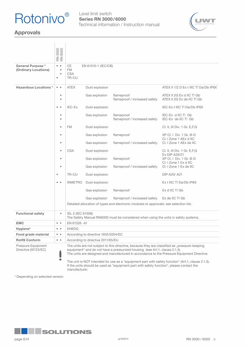
Approvals
* Depending on selected version
RN
300
0R
N 6
000
General Purpose *(Ordinary Locations)
• • • ••
CE EN 61010-1 (IEC/CB)FMCSATR-CU
Hazardous Locations * • •
• •
• •
• •
•
•
•
•
•
•
•
• •
ATEX
IEC-Ex
FM
CSA
TR-CU
INMETRO
Dust explosion
Gas explosion
Dust explosion
Gas explosion
Dust explosion
Gas explosion
Gas explosion
Dust explosion
Gas explosion
Gas explosion
Dust explosion
Dust explosion
Gas explosion
Gas explosion
flameproofflameproof / increased safety
flameproofflameproof / increased safety
flameproof
flameproof / increased safety
flameproof
flameproof / increased safety
flameproof
flameproof / increased safety
ATEX II 1/2 D Ex t IIIC T! Da/Db IP6X
ATEX II 2G Ex d IIC T! GbATEX II 2G Ex de IIC T! Gb
IEC-Ex t IIIC T! Da/Db IP6X
IEC-Ex d IIC T! Gb IEC-Ex de IIC T! Gb
Cl. II, III Div. 1 Gr. E,F,G
XP Cl. I Div. 1 Gr. B-D Cl. I Zone 1 AEx d IICCl. I Zone 1 AEx de IIC
Cl. II, III Div. 1 Gr. E,F,GEx DIP A20/21XP Cl. I Div. 1 Gr. B-D Cl. I Zone 1 Ex d IICCl. I Zone 1 Ex de IIC
DIP A20/ A21
Ex t IIIC T! Da/Db IP6X
Ex d IIC T! Gb
Ex de IIC T! Gb
Detailed allocation of types and electronic modules to approvals: see selection list.
Functional safety • SIL 2 (IEC 61508)The Safety Manual RN6000 must be considered when using the units in safety systems.
EMC • • EN 61326 -A1
Hygiene* • • EHEDG
Food grade material • • According to directive 1935/2004/EC
RoHS Conform • • According to directive 2011/65/EU
Pressure Equipment Directive (97/23/EC)
The units are not subject to this directive, because they are classified as „pressure-keeping equipment“ and do not have a pressurized housing (see Art.1, clause 2.1.4).The units are designed and manufactured in accordance to the Pressure Equipment Directive.
The unit is NOT intended for use as a "equipment part with safety function" (Art.1, clause 2.1.3).If the units should be used as "equipment part with safety function", please contact the manufacturer.
Rotonivo®1
2
3
4
5
6
7
8
9
10
11
12RN 3000 / 6000 cgi16091414
page G
Level limit switchSeries RN 3000 / 6000Technical information / Instruction manual
Options
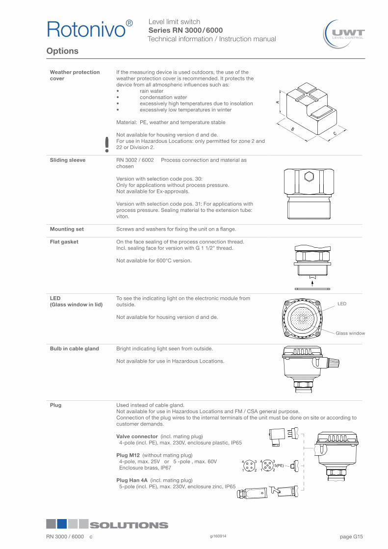
Weather protection cover
If the measuring device is used outdoors, the use of the weather protection cover is recommended. It protects the device from all atmospheric influences such as:• rain water• condensation water• excessively high temperatures due to insolation• excessively low temperatures in winter
Material: PE, weather and temperature stable
Not available for housing version d and de.For use in Hazardous Locations: only permitted for zone 2 and 22 or Division 2.
Sliding sleeve RN 3002 / 6002 Process connection and material as chosen
Version with selection code pos. 30:Only for applications without process pressure.Not available for Ex-approvals.
Version with selection code pos. 31: For applications with process pressure. Sealing material to the extension tube: viton.
Mounting set Screws and washers for fixing the unit on a flange.
Flat gasket On the face sealing of the process connection thread.Incl. sealing face for version with G 1 1/2" thread.
Not available for 600°C version.
LED(Glass window in lid)
To see the indicating light on the electronic module from outside.
Not available for housing version d and de.
Bulb in cable gland Bright indicating light seen from outside.
Not available for use in Hazardous Locations.
Plug Used instead of cable gland.Not available for use in Hazardous Locations and FM / CSA general purpose.Connection of the plug wires to the internal terminals of the unit must be done on site or according to customer demands.
Valve connector (incl. mating plug) 4-pole (incl. PE), max. 230V, enclosure plastic, IP65
Plug M12 (without mating plug) 4-pole, max. 25V or 5 -pole , max. 60V Enclosure brass, IP67
Plug Han 4A (incl. mating plug) 5-pole (incl. PE), max. 230V, enclosure zinc, IP65
LED
Glass window
RN 3000 / 6000 c gi160914 15
Rotonivo® 1
2
3
4
5
6
7
8
9
10
11
12
page G
Level limit switchSeries RN 3000 / 6000Technical information / Instruction manual
Process pressure Improper installation may result in loss of process pressure.
Chemical resistanceagainst the medium
Materials of construction are choosen based on their chemical compatibility (or inertness) for general purposes. For exposure to specific environments, check with chemical compatibility charts before installing.
Mechanical load The torque at the fastening spot must not exceed the specified ratings. See page G12 for details.
Mounting location Keep away from incoming material and from silo walls.The installation has to be carried out, that the sensor elements cannot hit the wall of the silo. The flow of the medium and fixtures in the container must be considered. This is especially important for extension length of more than 3000mm (118“)
Sliding sleeve Tighten both straining screws M8 with 20 Nmto obtain resistance against pressure
Flange mounting A plastic seal must be used to tighten the flange.
EHEDG-approval /Food grade material
The materials are available for the use under normal and predictable applications (according to directive 1935/2004 Art.3). Other conditions can influence the safety.
General Safety Instructions
Additional Safety Instructions for Hazardous Locations
Installation regulations For devices to be used in Hazardous Locations the respective valid installation regulations must be observed.
Sparks The installation has to be done in a way, that mechanical friction or impact does not cause sparks between the aluminium enclosure and steel.
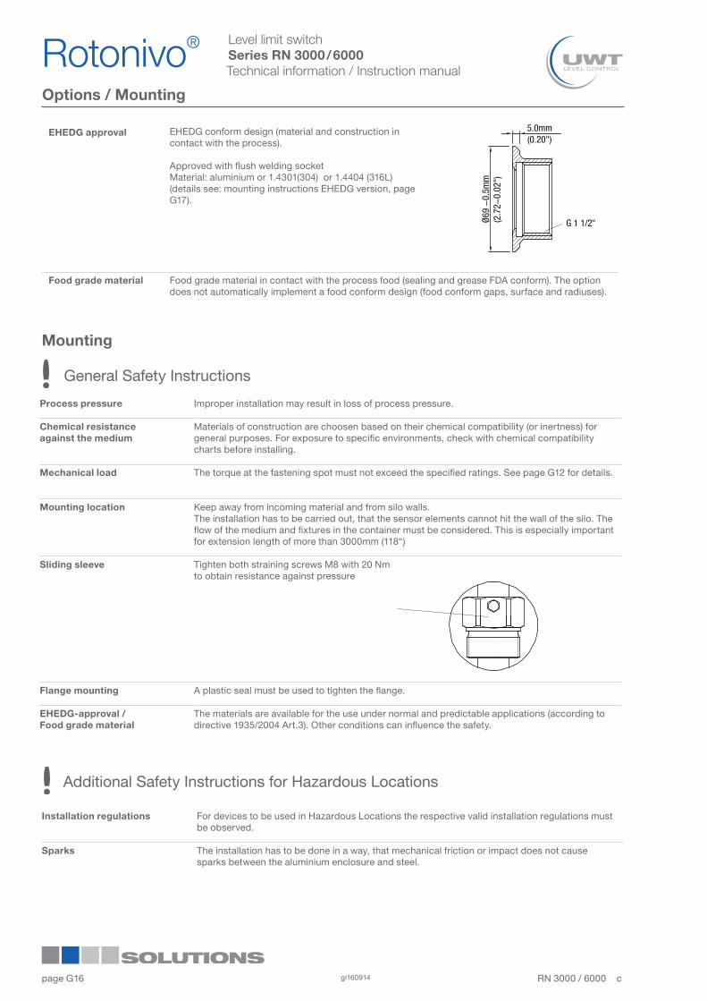
EHEDG approval EHEDG conform design (material and construction in contact with the process).
Approved with flush welding socketMaterial: aluminium or 1.4301(304) or 1.4404 (316L)(details see: mounting instructions EHEDG version, page G17).
Food grade material Food grade material in contact with the process food (sealing and grease FDA conform). The option does not automatically implement a food conform design (food conform gaps, surface and radiuses).
Mounting
Options / Mounting
Rotonivo®1
2
3
4
5
6
7
8
9
10
11
12RN 3000 / 6000 cgi16091416
page G
Level limit switchSeries RN 3000 / 6000Technical information / Instruction manual
Mounting
Mounting instructions
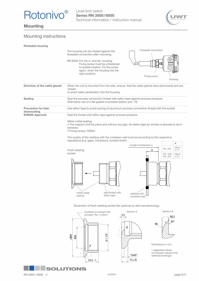
The housing can be rotated against the threaded connection after mounting.
RN 6000: For the d- and de- housing: Fixing screw must be unfastened to enable rotation. Fix the screw again, when the housing has the right position.
Threaded connection
Fixing screwHousing
metal-metalsealing
seal thread with teflon tape
welding with container wall
Flush welding socket
Dimension of flush welding socket (for optional on site manufacturing):
Length of extension L
Surfaces in contact with process Ra <=0.8um
Section A Section B
Dimensions in mm
* suggested values(in brackets values to be adhered bindingly)
Rotatable housing
Direction of the cable glands When the unit is mounted from the side, ensure, that the cable glands face downwards and are closedto avoid water penetration into the housing.
Sealing Seal the process connection thread with teflon tape against process pressure.Alternative use of a flat gasket is possible (option pos. 15)
Precaution for later dismounting
Use teflon tape to avoid seizing of aluminium process connection thread with the socket
EHEDG-Approval Seal the thread with teflon tape against process pressure.
Metal-metal sealing:• The support muß be plane and without any gap. No teflon tape (or similar) is allowed to be in between. • Fixing torque 100Nm
The quality of the welding with the container wall must be according to the respective regulations (e.g. gaps, transitions, surface finish).
RN 3000 / 6000 c gi160914 17
Rotonivo® 1
2
3
4
5
6
7
8
9
10
11
12
A
RN ..00128mm (1.1”)
RN ..002/RN ..004
38mm (1.5”)
page G
Level limit switchSeries RN 3000 / 6000Technical information / Instruction manual
Mounting
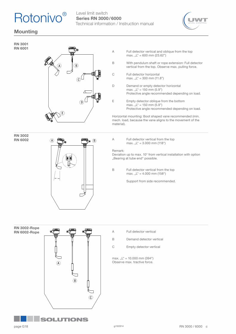
RN 3001RN 6001
A Full detector vertical and oblique from the top max. „L“ = 600 mm (23.62”) B With pendulum shaft or rope extension: Full detector vertical from the top. Observe max. pulling force.
C Full detector horizontal max. „L“ = 300 mm (11.8”)
D Demand or empty detector horizontal max. „L“ = 150 mm (5.9”) Protective angle recommended depending on load.
E Empty detector oblique from the bottom max. „L“ = 150 mm (5.9”) Protective angle recommended depending on load.
Horizontal mounting: Boot shaped vane recommended (min. mech. load, because the vane aligns to the movement of the material).
RN 3002RN 6002 A Full detector vertical from the top
max. „L“ = 3.000 mm (118“)
Remark:Deviation up to max. 10° from vertical installation with option „Bearing at tube end“ possible.
B Full detector vertical from the top max. „L“ = 4.000 mm (158“)
Support from side recommended.
RN 3002-RopeRN 6002-Rope A Full detector vertical
B Demand detector vertical
C Empty detector vertical
max. „L“ = 10.000 mm (394“)Observe max. tractive force.
Rotonivo®1
2
3
4
5
6
7
8
9
10
11
12RN 3000 / 6000 cgi16091418
page G
Level limit switchSeries RN 3000 / 6000Technical information / Instruction manual
Mounting
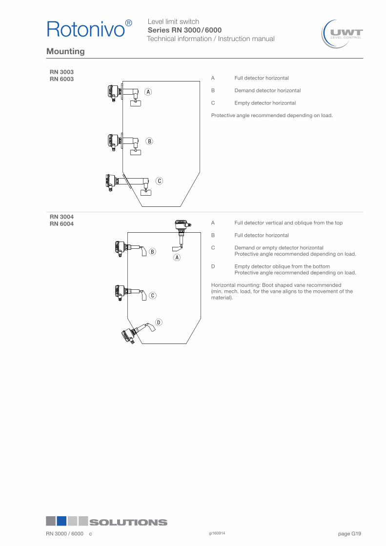
RN 3003RN 6003 A Full detector horizontal
B Demand detector horizontal
C Empty detector horizontal
Protective angle recommended depending on load.
RN 3004RN 6004 A Full detector vertical and oblique from the top
B Full detector horizontal
C Demand or empty detector horizontal Protective angle recommended depending on load.
D Empty detector oblique from the bottom Protective angle recommended depending on load.
Horizontal mounting: Boot shaped vane recommended (min. mech. load, for the vane aligns to the movement of the material).
RN 3000 / 6000 c gi160914 19
Rotonivo® 1
2
3
4
5
6
7
8
9
10
11
12

page G
Level limit switchSeries RN 3000 / 6000Technical information / Instruction manual
Electrical installation
Handling In the case of improper handling or handling malpractice, the electric safety of the device cannot be guaranteed.
Installation regulations The local regulations or VDE 0100 (Regulations of German Electrotechnical Engineers) must be observed.WIth use of 24V supply voltage, an approved power supply with reinforced insulation to mains is required.
Fuse Use a fuse as stated in the connection diagrams (see pages G23 and G24).
RCCB protection In the case of a fault, the supply voltage must be automatically switched off by a RCCB protection switch to protect against indirect contact with dangerous voltages.
Power supply switch A voltage disconnection switch must be provided near the device.
Wiring diagram The electrical connections are made in accordance with the wiring diagram.
Supply voltage Compare the supply voltage applied with the specifications given on the electronic module and name plate before switching the device on.
Cable gland The screwed cable gland and closing element must have following specifications: Ingress protection IP66, temperature range from -40°C to +70°C, UL or VDE or INMETRO certified (depending on the country where the unit is installed), pull relief. Make sure that the screwed cable gland safely seals the cable and that it is tight (danger of water intrusion). Cable glands that are not used have to be sealed with a blanking element.The diameter of the field wiring cable has to match to the clamping range of the used cable gland.
Conduit system In case of using a conduit system (with NPT thread) instead of a cable gland the regulations of the country, where the unit is installed, must be observed. The conduit must have a tapered thread either NPT1/2“ or NPT3/4” in accordance with the unit and ANSI B 1.20.1. Not used inlets must be closed tight with a metal blanking element.
Field wiring cables • The diameter has to match to the clamping range of the used cable gland.• The cross section has to match with the clamping range of the connection terminals and consider the max. current. • All field wirings must have insulation suitable for at least 250V AC. • The temperature rating must be at least 90°C (194°F).• If higher immunity interferences as specified in the stated EMC standards are present (see chapter approval), a shielded cable is required, otherwise an unshielded instrumentation cable is satisfactory.
Guiding the cables in the terminal box
Cut the field wiring cables to appropriate length to fit properly into the terminal box.
Microswitch protection Provide protection for microswitch contacts to protect the device against inductive load surges.
Protection against static charging
The housing of the unit must be grounded to avoid static charging of the unit. This is particularly important for applications with pneumatic conveying and non-metallic containers.
General Safety Instructions
External equipotential bonding terminal
RN 3000 RN 6000
Additional Safety Instructions for Hazardous Locations
Connect to equipotential bonding of the plant
Rotonivo®1
2
3
4
5
6
7
8
9
10
11
12RN 3000 / 6000 cgi16091420
page G
Level limit switchSeries RN 3000 / 6000Technical information / Instruction manual
Electrical installation
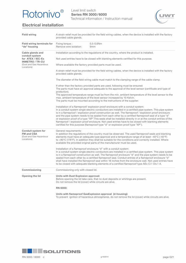
Field wiring A strain relief must be provided for the field wiring cables, when the device is installed with the factory provided cable glands.
Field wiring terminals for “de” housing
Fixing torque : 0,5-0,6NmRemove wire isolation: 9mm
Cable glands and conduit systemfor ATEX / IEC-ExINMETRO / TR-CU (Dust and Gas Hazardous Locations)
Installation according to the regulations of the country, where the product is installed.
Not used entries have to be closed with blanking elements certified for this purpose.
Where available the factory provided parts must be used.
A strain relief must be provided for the field wiring cables, when the device is installed with the factoryprovided cable glands.
The diameter of the field wiring cable must match to the clamping range of the cable clamp.
If other than the factory provided parts are used, following must be ensured:The parts must have an approval adequate to the approval of the level sensor (certificate and type of protection).The approved temperature range must be from the min. ambient temperature of the level sensor to the max. ambient temperature of the level sensor increased by 10 Kelvin. The parts must be mounted according to the instructions of the supplier. Installation of a flameproof/ explosion proof enclosure with a conduit system:In a conduit system single electric conductors are installed in a certified pipe system. This pipe system is in a flameproof / explosion proof construction as well. The flameproof / explosion proof enclosure and the pipe system needs to be sealed from each other by a certified flameproof seal of a type “d” or explosion proof of a type “XP”.This seals shall be installed directly in or at the conduit entries of the flameproof / explosion proof enclosure. Not used entries have to be closed with blanking elements certified for this purpose (flameproof type “d” or explosion proof type “XP”).
Conduit system for FM and CSA (Dust and Gas Hazardous Locations)
General requirements:In addition the regulations of the country must be observed. The used flameproof seals and blanking elements must have an adequate type approval and a temperature range of at least –40°C (-40°F) to +80°C (176°F). In addition they shall be suitable for the conditions and correctly installed. Where available the provided original parts of the manufacturer must be used.
Installation of a flameproof enclosure “d” with a conduit system:In a conduit system single electric conductors are installed in a certified pipe system. This pipe system is in a flameproof construction as well. The flameproof enclosure “d” and the pipe system needs to be sealed from each other by a certified flameproof seal. Conduit entries of a flameproof enclosure “d” shall have installed the flameproof seal within 18 inches from the enclosure wall. Not used entries have to be closed with adequate blanking elements of a certified flameproof type AEx Cl.1 Div.1 A.
Commissioning Commissioning only with closed lid.
Opening the lid Units with Dust Explosion approval:Before opening the lid take care, that no dust deposits or whirlings are present.Do not remove the lid (cover) while circuits are alive.
RN 6000:
Units with flameproof GasExplosion approval (d-housing):To prevent ignition of hazardous atmospheres, do not remove the lid (cover) while circuits are alive.
RN 3000 / 6000 c gi160914 21
Rotonivo® 1
2
3
4
5
6
7
8
9
10
11
12
page G
Level limit switchSeries RN 3000 / 6000Technical information / Instruction manual
Electrical installation
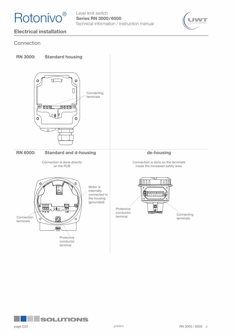
Connection
RN 3000: Standard housing
RN 6000: Standard and d-housing de-housing
Connection is done directlyon the PCB
Connection is done on the terminalsinside the increased safety area.
Connecting terminals
Motor is internally connected to the housing (grounded)
Connection terminals
Protective conductor terminal
Protective conductor terminal
Connecting terminals
Rotonivo®1
2
3
4
5
6
7
8
9
10
11
12RN 3000 / 6000 cgi16091422
page G
Level limit switchSeries RN 3000 / 6000Technical information / Instruction manual
* Protection against static charge:The PE terminal of the unit must be grounded to avoid static charging of the unit.This is particularly important for applications with pneumatic conveying.
Electrical installation Series RN 3000
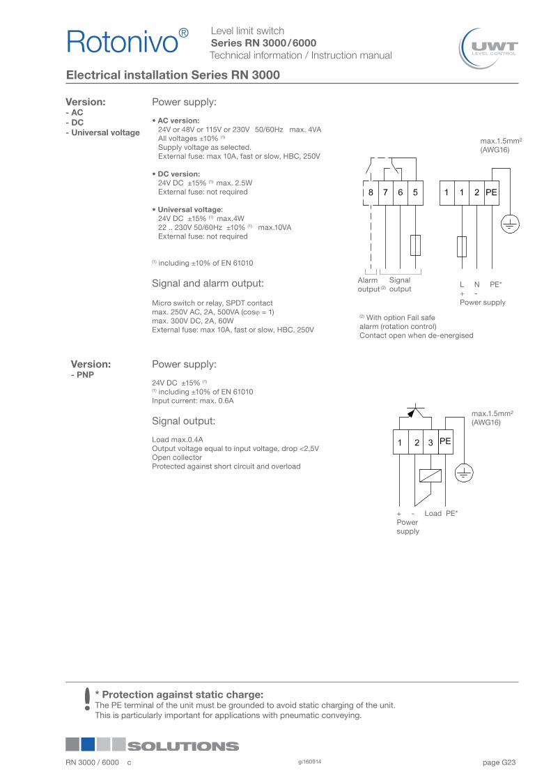
Version:- AC- DC- Universal voltage
Power supply:
• AC version: 24V or 48V or 115V or 230V 50/60Hz max. 4VA All voltages ±10% (1) Supply voltage as selected. External fuse: max 10A, fast or slow, HBC, 250V
• DC version: 24V DC ±15% (1) max. 2.5W External fuse: not required
• Universal voltage: 24V DC ±15% (1) max.4W 22 .. 230V 50/60Hz ±10% (1) max.10VA External fuse: not required
(1) including ±10% of EN 61010
Signal and alarm output:
Micro switch or relay, SPDT contactmax. 250V AC, 2A, 500VA (cosj = 1)max. 300V DC, 2A, 60W External fuse: max 10A, fast or slow, HBC, 250V
Version:- PNP
Power supply:
24V DC ±15% (1)
(1) including ±10% of EN 61010Input current: max. 0.6A
Signal output:
Load max.0.4AOutput voltage equal to input voltage, drop <2,5VOpen collectorProtected against short circuit and overload
max.1.5mm² (AWG16)
L N PE* + -Power supply
Signal output
Alarm output (2)
(2) With option Fail safealarm (rotation control)Contact open when de-energised
+ - Load PE* Power supply
max.1.5mm² (AWG16)
RN 3000 / 6000 c gi160914 23
Rotonivo® 1
2
3
4
5
6
7
8
9
10
11
12
page G
Level limit switchSeries RN 3000 / 6000Technical information / Instruction manual
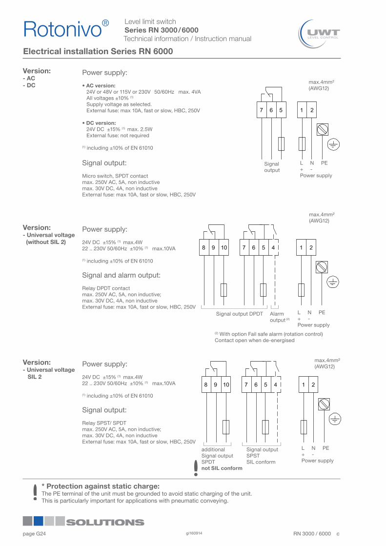
Electrical installation Series RN 6000
Version:- AC- DC
Power supply:
• AC version: 24V or 48V or 115V or 230V 50/60Hz max. 4VA All voltages ±10% (1) Supply voltage as selected. External fuse: max 10A, fast or slow, HBC, 250V
• DC version: 24V DC ±15% (1) max. 2.5W External fuse: not required
(1) including ±10% of EN 61010
Signal output:
Micro switch, SPDT contactmax. 250V AC, 5A, non inductivemax. 30V DC, 4A, non inductive External fuse: max 10A, fast or slow, HBC, 250V
Version:- Universal voltage (without SIL 2)
Version:- Universal voltage SIL 2
Power supply:
24V DC ±15% (1) max.4W22 .. 230V 50/60Hz ±10% (1) max.10VA
(1) including ±10% of EN 61010
Signal output:
Relay SPST/ SPDTmax. 250V AC, 5A, non inductive;max. 30V DC, 4A, non inductive External fuse: max 10A, fast or slow, HBC, 250V
Power supply:
24V DC ±15% (1) max.4W22 .. 230V 50/60Hz ±10% (1) max.10VA
(1) including ±10% of EN 61010
Signal and alarm output:
Relay DPDT contactmax. 250V AC, 5A, non inductive;max. 30V DC, 4A, non inductive External fuse: max 10A, fast or slow, HBC, 250V
* Protection against static charge:The PE terminal of the unit must be grounded to avoid static charging of the unit.This is particularly important for applications with pneumatic conveying.
max.4mm² (AWG12)
Signal output
L N PE + -Power supply
max.4mm² (AWG12)
L N PE+ -Power supply
Alarm output (2)
Signal output DPDT
(2) With option Fail safe alarm (rotation control) Contact open when de-energised
max.4mm² (AWG12)
additional Signal output SPDTnot SIL conform
Signal outputSPSTSIL conform
L N PE+ -Power supply
Rotonivo®1
2
3
4
5
6
7
8
9
10
11
12RN 3000 / 6000 cgi16091424
page G
Level limit switchSeries RN 3000 / 6000Technical information / Instruction manual
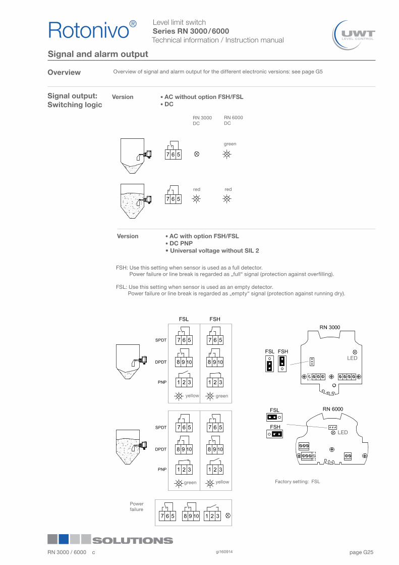
Signal and alarm output
Overview
Signal output:Switching logic
Factory setting: FSL
FSH: Use this setting when sensor is used as a full detector. Power failure or line break is regarded as „full“ signal (protection against overfilling).
FSL: Use this setting when sensor is used as an empty detector. Power failure or line break is regarded as „empty“ signal (protection against running dry).
Power failure
RN 3000DC
RN 6000 DC
green
redred
Overview of signal and alarm output for the different electronic versions: see page G5
LED
Version • AC without option FSH/FSL • DC
Version • AC with option FSH/FSL • DC PNP • Universal voltage without SIL 2
greenyellow
yellowgreen
LED
RN 3000 / 6000 c gi160914 25
Rotonivo® 1
2
3
4
5
6
7
8
9
10
11
12
page G
Level limit switchSeries RN 3000 / 6000Technical information / Instruction manual
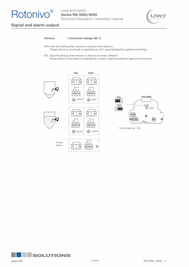
Signal and alarm output
Version • Universal voltage SIL 2
greenyellow
yellowgreen
LED
FSH: Use this setting when sensor is used as a full detector. Power failure or line break is regarded as „full“ signal (protection against overfilling).
FSL: Use this setting when sensor is used as an empty detector. Power failure or line break is regarded as „empty“ signal (protection against running dry).
Factory setting: FSL
Power failure
Rotonivo®1
2
3
4
5
6
7
8
9
10
11
12RN 3000 / 6000 cgi16091426

page G
Level limit switchSeries RN 3000 / 6000Technical information / Instruction manual
Signal and alarm output
Signal output:Delay Sensor covered -> free
Factory setting = 3 sec
Sensor free -> coveredFactory setting = 1 sec
No fault Fault
Switching and timing behaviour:If the sensor is not covered, the rotating paddle shaft will send pulses at 20 sec intervals. In case of fault, the pulses are missed. After 30 sec the alarm relay will open.
Signal output
Connection example:
Full detector with maximum safety:The output signal opens in case of:• full signal or • failure of supply voltage or • defect of the connection wires or• defective unit
LED
LED
yellow or green (see page before) red
yellow or green (see page before) red
No fault Fault
RN 3000 Universal voltage
Alarm output(Fail safe alarm,Rotation control)
RN 6000 Universal voltage(without SIL 2)
RN 3000 / 6000 c gi160914 27
Rotonivo® 1
2
3
4
5
6
7
8
9
10
11
12
RN3000 RN6000
page G
Level limit switchSeries RN 3000 / 6000Technical information / Instruction manual
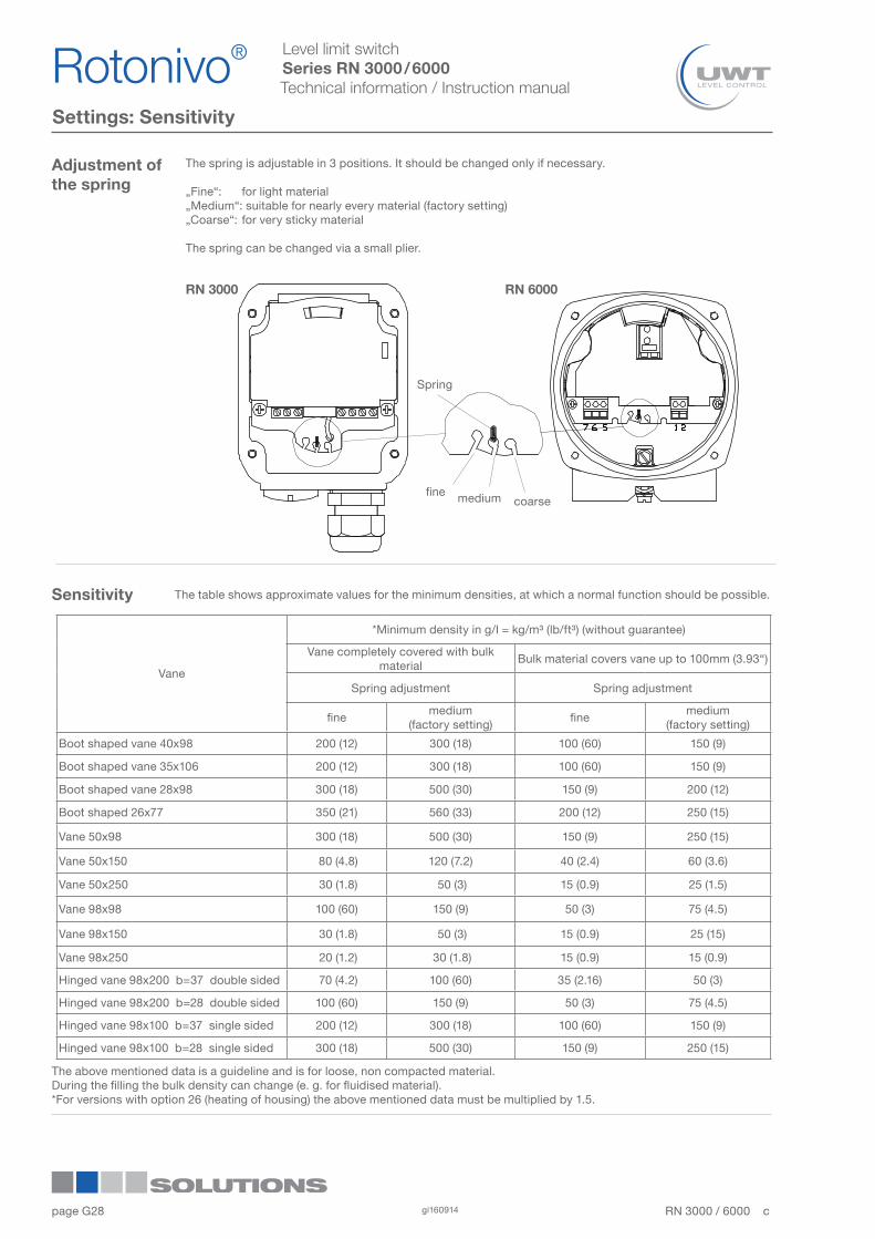
Settings: Sensitivity
Adjustment ofthe spring
The spring is adjustable in 3 positions. It should be changed only if necessary.
„Fine“: for light material„Medium“: suitable for nearly every material (factory setting)„Coarse“: for very sticky material
The spring can be changed via a small plier.
RN 3000 RN 6000
fine medium coarse
Spring
The table shows approximate values for the minimum densities, at which a normal function should be possible.
The above mentioned data is a guideline and is for loose, non compacted material.During the filling the bulk density can change (e. g. for fluidised material).*For versions with option 26 (heating of housing) the above mentioned data must be multiplied by 1.5.
Sensitivity
Vane
*Minimum density in g/l = kg/m³ (lb/ft³) (without guarantee)
Vane completely covered with bulk material
Bulk material covers vane up to 100mm (3.93“)
Spring adjustment Spring adjustment
finemedium
(factory setting)fine
medium(factory setting)
Boot shaped vane 40x98 200 (12) 300 (18) 100 (60) 150 (9)
Boot shaped vane 35x106 200 (12) 300 (18) 100 (60) 150 (9)
Boot shaped vane 28x98 300 (18) 500 (30) 150 (9) 200 (12)
Boot shaped 26x77 350 (21) 560 (33) 200 (12) 250 (15)
Vane 50x98 300 (18) 500 (30) 150 (9) 250 (15)
Vane 50x150 80 (4.8) 120 (7.2) 40 (2.4) 60 (3.6)
Vane 50x250 30 (1.8) 50 (3) 15 (0.9) 25 (1.5)
Vane 98x98 100 (60) 150 (9) 50 (3) 75 (4.5)
Vane 98x150 30 (1.8) 50 (3) 15 (0.9) 25 (15)
Vane 98x250 20 (1.2) 30 (1.8) 15 (0.9) 15 (0.9)
Hinged vane 98x200 b=37 double sided 70 (4.2) 100 (60) 35 (2.16) 50 (3)
Hinged vane 98x200 b=28 double sided 100 (60) 150 (9) 50 (3) 75 (4.5)
Hinged vane 98x100 b=37 single sided 200 (12) 300 (18) 100 (60) 150 (9)
Hinged vane 98x100 b=28 single sided 300 (18) 500 (30) 150 (9) 250 (15)
Rotonivo®1
2
3
4
5
6
7
8
9
10
11
12RN 3000 / 6000 cgi16091428
page G
Level limit switchSeries RN 3000 / 6000Technical information / Instruction manual
Maintenance
Opening the lid (cover) Before opening the lid for maintenance reasons observe following items:• Do not remove the lid while circuits are live.• No dust deposits or whirlings are present.• No rain can enter into the housing.
Frequent check of the unit
To ensure durable safety in hazardous locations and with electrical safety, following items must be checked frequently depending on the application:• Mechanical damage or corrsion of any components (housing side and sensor side) and of the field wiring cables. • Thight sealing of the process connection, cable glands and enclosure lid.. • Properly connected external PE cable (if present).
Cleaning If cleaning is required by the application, following must be observed:• Cleaning agent must comply with the materials of the unit (chemical resistance). Mainly the shaft sealing, lid sealing, cable gland and the surface of the unit must be considered.
The cleaning process must be done in a way, that:• The cleaning agent cannot enter into the unit through the shaft sealing, lid sealing or cable gland.• No mechanical damage of the shaft sealing, lid sealing, cable gland or other parts can happen.
A possible accumulation of dust on the unit does not increase the maximum surface temperature and must therefore not be removed for purposes of maintaining the surface temperature in hazardous locations.
Function test A frequent function test may be required depending on the application. Observe all relevant safety precautions related with a safe work depending on the application (e.g. hazardous locations, hazardous bulk material, electrical safety, process pressure).
This test does not proof if the sensor is sensitive enough to measure the material of the application.
Function test is done by stopping the rotating paddle with appropriate means and monitor if a correct change of the signal output from uncovered to covered happens.
Production date The production date can be traced by the serial number on the typeplate. Please contact the manufacturer or your local distrubutor.
Spare parts All available spare parts are stated in the selection list.
RN 3000 / 6000 c gi160914 29
Rotonivo® 1
2
3
4
5
6
7
8
9
10
11
12
page G
Level limit switchSeries RN 3000 / 6000Technical information / Instruction manual
Notes for use in Hazardous Locations
Zone classification
Useable in zone ATEXCategory
IEC-Ex / INMETROEquipement Protection Level (EPL)
*) in case of conductive dust additional requirements for the installation are necessary.
Dust applications 20, 21, 22 1 D Da21, 22 2 D Db22 3 D * Dc
Gas applications 0, 1, 2 1 G Ga1, 2 2 G Gb2 3 G Gc
General Notes
Marking Devices with Ex approval are marked on name plate.
Process pressure The device construction allows process over-pressure up to 0.8/5/10 bar (11.6/73/145psi) (see name plate). These pressures are allowed for test purposes. The definition of the Ex approvals are only valid for a container-over-pressure between -0.2..+0.1 bar (-2.9..+1.45psi). For higher or lower pressures the approvals are not valid.
Process and ambienttemperature
The permitted temperature ranges are marked on the name plate.
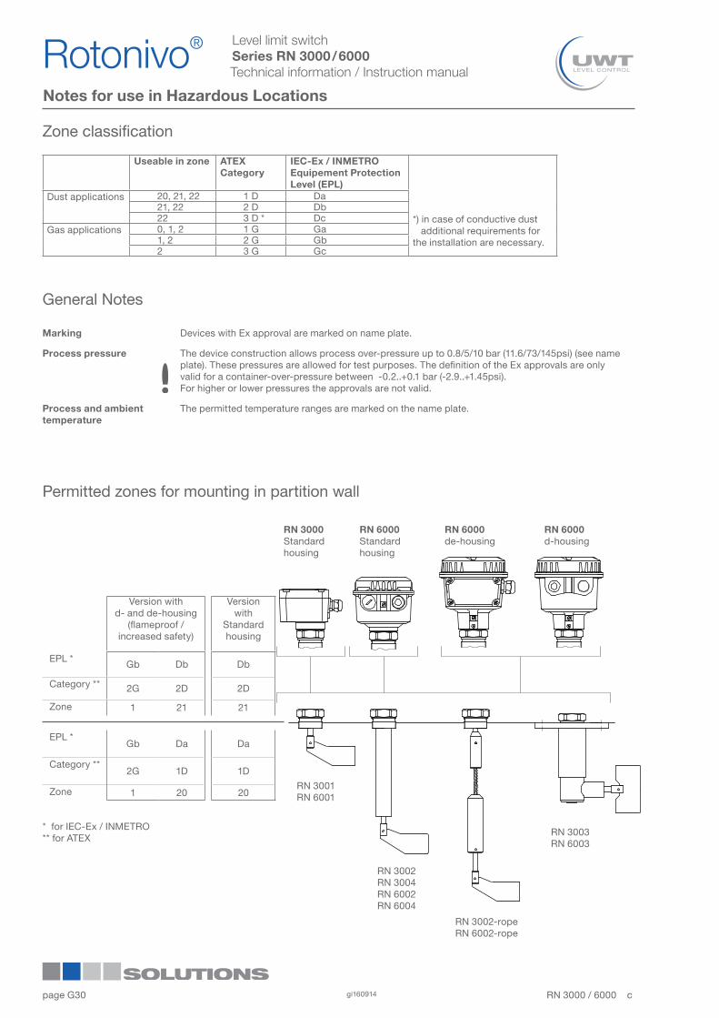
Permitted zones for mounting in partition wall
RN 3000Standardhousing
RN 6000Standardhousing
RN 6000de-housing
RN 6000d-housing
RN 3002RN 3004RN 6002RN 6004
RN 3002-ropeRN 6002-rope
RN 3003RN 6003
RN 3001RN 6001
Version with d- and de-housing
(flameproof / increased safety)
Version with
Standardhousing
EPL *Gb Db Db
Category ** 2G 2D 2D
Zone 1 21 21
EPL *Gb Da Da
Category **2G 1D 1D
Zone 1 20 20
* for IEC-Ex / INMETRO** for ATEX
Rotonivo®1
2
3
4
5
6
7
8
9
10
11
12RN 3000 / 6000 cgi16091430
page G
Level limit switchSeries RN 3000 / 6000Technical information / Instruction manual
Notes for use in Hazardous Locations
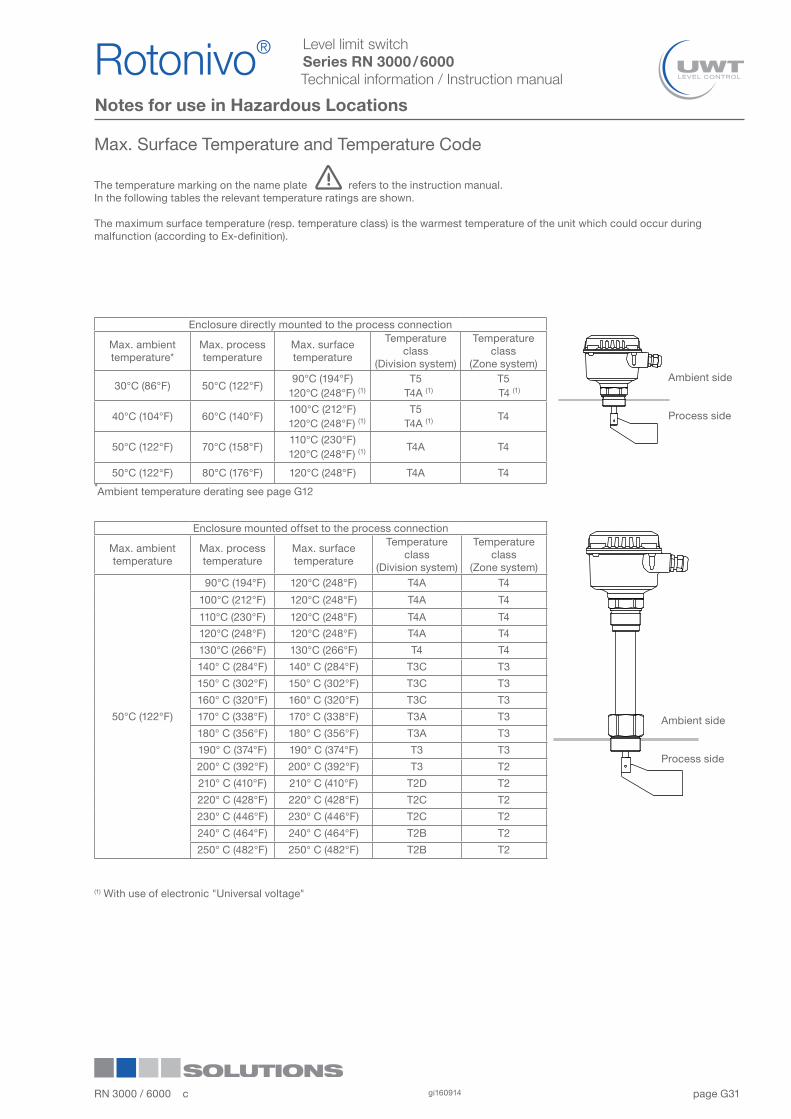
Max. Surface Temperature and Temperature Code
The temperature marking on the name plate refers to the instruction manual.In the following tables the relevant temperature ratings are shown.
The maximum surface temperature (resp. temperature class) is the warmest temperature of the unit which could occur during malfunction (according to Ex-definition).
(1) With use of electronic "Universal voltage"
Ambient side
Process side
Ambient side
Process side
Enclosure directly mounted to the process connection
Max. ambient temperature*
Max. process temperature
Max. surfacetemperature
Temperature class
(Division system)
Temperature class
(Zone system)
30°C (86°F) 50°C (122°F)90°C (194°F)
120°C (248°F) (1)
T5 T4A (1)
T5 T4 (1)
40°C (104°F) 60°C (140°F)100°C (212°F)
120°C (248°F) (1)
T5 T4A (1) T4
50°C (122°F) 70°C (158°F)110°C (230°F)
120°C (248°F) (1) T4A T4
50°C (122°F) 80°C (176°F) 120°C (248°F) T4A T4*Ambient temperature derating see page G12
Enclosure mounted offset to the process connection
Max. ambient temperature
Max. process temperature
Max. surfacetemperature
Temperature class
(Division system)
Temperature class
(Zone system)
50°C (122°F)
90°C (194°F) 120°C (248°F) T4A T4
100°C (212°F) 120°C (248°F) T4A T4
110°C (230°F) 120°C (248°F) T4A T4
120°C (248°F) 120°C (248°F) T4A T4
130°C (266°F) 130°C (266°F) T4 T4
140° C (284°F) 140° C (284°F) T3C T3
150° C (302°F) 150° C (302°F) T3C T3
160° C (320°F) 160° C (320°F) T3C T3
170° C (338°F) 170° C (338°F) T3A T3
180° C (356°F) 180° C (356°F) T3A T3
190° C (374°F) 190° C (374°F) T3 T3
200° C (392°F) 200° C (392°F) T3 T2
210° C (410°F) 210° C (410°F) T2D T2
220° C (428°F) 220° C (428°F) T2C T2
230° C (446°F) 230° C (446°F) T2C T2
240° C (464°F) 240° C (464°F) T2B T2
250° C (482°F) 250° C (482°F) T2B T2
RN 3000 / 6000 c gi160914 31
Rotonivo® 1
2
3
4
5
6
7
8
9
10
11
12
page G
Level limit switchSeries RN 3000 / 6000Technical information / Instruction manual
Disposal
The product consists of materials which can be recycled, details of the used materials see chapter "Technical data - mechanical data". Recycling must be done by a specialised recycling company. Since the product is not subject to the WEEE directive 2002/96/EG, it is not permitted to bring it to a public recycling station.
Rotonivo®1
2
3
4
5
6
7
8
9
10
11
12RN 3000 / 6000 cgi16091432