Embed Size (px)
DESCRIPTION
cnhcncv
Citation preview

In a typical ISP environment, an AS contains many BGP-speaking routers. Fully meshing all these iBGP
speakers would result in both a high BGP session count and high resource consumption per router. This
chapter focuses on two common solutions—route reflection and confederation. Using these two solutions,
this chapter demonstrates practical guidelines with extensive examples of how to design a scalable iBGP
routing architecture.
Through four case studies in Chapter 8, ―Route Reflection and Confederation Migration
Strategies,‖ which contain step-by-step migration procedures, you will further explore the subject of iBGP
scalability.
Issues of iBGP Scalability
As you recall, the subject of loop prevention mechanisms in BGP was introduced in Chapter 2,
―Understanding BGP Building Blocks.‖ When BGP is used to distribute reachability information among a
series of autonomous systems, as is the case with eBGP, the BGP attribute AS_PATH is used as the loop-
prevention mechanism. An eBGP speaker discards any BGP updates it receives from an eBGP peer that
contains its own AS number. Because the AS_PATH attribute is preserved within the same AS, a different
loop-prevention mechanism must be employed for iBGP. The rule is simply that an iBGP speaker does not
relay or readvertise reachability information received via iBGP from one iBGP speaker to another iBGP
speaker. For example, if routers R1, R2, and R3 are all iBGP-only speakers within the same AS, and R2
receives a prefix from R1, R2 does not send that prefix via iBGP to R3.
The loop-prevention mechanism within iBGP forces all iBGP speakers to have BGP sessions with each
other. In other words, they are fully meshed so that all BGP speakers can receive full routing information. In
the example given in the preceding paragraph, fully meshed means that R1 needs to have BGP sessions with
R2 and R3. Also, R2 and R3 must peer with each other via iBGP. The total number of iBGP sessions among
n iBGP routers is n(n–1)/2, with each router having (n–1) sessions. Figure 7-1 shows the relationship
between the total number of iBGP sessions and the number of fully meshed iBGP routers, commonly called
the n2 relationship. For example, when the number of iBGP routers increases from 10 to 100, the total
number of iBGP sessions increases from 45 to 4950!
Two effective approaches to solve the iBGP scalability issue are route reflection (RFC 2796) and
confederation (RFC 3065). Route reflection is based on relaxing the iBGP loopprevention requirement for
certain types of routers, whereas confederation is a method of breaking a large AS into a number of smaller
member autonomous systems. Either way, the number of iBGP sessions can be reduced to a manageable
level.
Route Reflection
This section discusses various aspects of route reflection:
• How route reflection works
• Rules for prefix advertisement
• Clustering
• Loop-prevention mechanisms
• Hierarchical route reflection
• Route reflection design examples
How Route Reflection Works
Route reflection involves creating a special group of routers called route reflectors (RRs). The iBGP loop-
prevention rule is relaxed for these routers, in that with certain restrictions they are allowed to readvertise or
reflect routes from one iBGP speaker to another iBGP speaker. Under this new structure, iBGP speakers are
classified into three groups:
• Route reflectors (RRs)
• Route reflector clients (also known as clients or client peers)
• Regular iBGP speakers (also known as nonclients or nonclient peers)

NOTE The concept of clients and nonclients is always in the context of the RRs that serve or do not serve
them. A client of one RR can be an RR of another client. A nonclient with respect to one RR can be an RR
of another client.
Route reflectors, although acting like regular iBGP speakers with other regular iBGP speakers and with each
other, can reflect routes between clients and nonclients. This includes reflecting routes from one client to
another client—in other words, client-to-client reflection. With route reflection, the full iBGP mesh is
required only between RRs and between RRs and nonclients.
Consider the topology shown in Figure 7-2, which shows three interconnected autonomous systems. Within
AS 200, R5 is an RR, with R6 and R7 as its clients. Routers R3 and R4 are nonclients and are fully meshed
with R5. Clients R6 and R7 have iBGP sessions only with R5. The total number of iBGP sessions within AS
200 is 5. Without route reflection, the total number of iBGP sessions within AS 200 would be 10.
Route reflection provides another scalability feature—an RR reflects only the best path of each prefix. When
an RR receives multiple paths for the same destination, it first steps through the path-selection process to
determine the best path for that destination. It then reflects the best path. Abstraction of routing information
by RRs reduces the size of the BGP RIB in the domain. Note that this abstraction is different from BGP
prefix summarization, although both reduce the size of the routing entries. One side effect of the RR’s
abstraction of routing information, however, is that inconsistent route selection between RRs and their peers
might result in a loss of routing information or routing loops. This chapter details how to avoid this type of
problem when implementing RR designs.
To maintain consistent BGP topology, RRs do not modify certain BGP path attributes during route
reflection. These attributes include NEXT_HOP, AS_PATH, LOCAL_PREF, and MED. Two additional
attributes are introduced to help prevent routing information loops in an RR environment,
ORIGINATOR_ID and CLUSTER_LIST. Both are discussed later. A routing information loop, also
discussed later, is a phenomenon that a router receives and accepts the routing information originated by
itself.

Rules for Prefix Advertisement
Before discussing the rules for prefix advertisement, a definition is in order. As a special form of prefix
advertisement, reflection is the advertisement made by an RR for prefixes learned from one client to another
client, from a client to a nonclient, or from a nonclient to a client. In this definition, the following
advertisements are not examples of reflection: from an external peer to an RR, from an RR to an external
peer, or from an RR to an internal peer (client or nonclient) for a prefix learned from an external peer. In
summary, reflection is a concept that is introduced with RRs and is used as a subset of the advertisement
concept.
To avoid creating routing information loops, certain rules must be followed during prefix advertisement
involving RRs:
• Rule 1—An RR advertises or reflects only its best path.
• Rule 2—An RR always advertises to eBGP peers
• Rule 3—An RR client follows the regular iBGP loop-prevention rule when advertising prefixes.
• Rule 4—Additional rules must be followed if advertising to iBGP peers, clients, or nonclients (see Rules
5, 6, and 7). When advertising to iBGP peers, the rules are dependent on where the prefix is learned.
• Rule 5—If an RR learns a prefix from an external peer, it advertises to all its clients and non clients.
Consider Figure 7-3, in which the RR (R5) receives the prefix 172.16.0.0/16 from an eBGP peer (R8). It
advertises the route to both its clients, R6 and R7. R5 also advertises the route to its nonclients, R3 and R4.
Both R3 and R4 are iBGP peered and are not allowed to readvertise the route to each other
• Rule 6—If the prefix comes to an RR through a nonclient iBGP peer, the RR reflects the route to all its
clients Figure 7-4 shows the prefix advertisement. The prefix 172.16.0.0/16 is advertised to R5 via iBGP
from R3. R5 reflects the prefix to its clients, R6 and R7. An RR does not reflect the route it learns from an
iBGP peer to another nonclient iBGP peer, such as R4 (standard iBGP requirement). Because R3 and R4 are
iBGP peered, R4 receives the prefix from R3 directly. As indicated in Rule 2, an RR always advertises to an
external peer, such as R8

• Rule 7—If a prefix comes to an RR from a client, the RR reflects the route to all other clients and non-
clients. In Figure 7-5, the prefix 172.16.0.0/16 is advertised to R5 (RR) by R7 (client), and R5 readvertises
or reflects the prefix to R6 (client), R3 (nonclient), and R4 (nonclient). As always, R5 advertises the prefix
to its external peer, R8 (Rule 2).
NOTE - If all clients are in the same peer group, an RR reflects the prefix received from a client to all
clients, including the client that sources the prefix. Route reflection and peer groups are discussed later in
this chapter.
Clustering
Clustering is introduced to provide redundancy in an RR environment. In a traditional clustering design,
multiple RRs are used to serve one or more clients. These RRs are configured with an identical
CLUSTER_ID, which is a 4-byte BGP attribute that commonly takes the form of an IP address and defaults
to the BGP router ID. If two routers share the same CLUSTER_ID, they belong to the same cluster. An
advertisement that bears the same CLUSTER_ID is ignored by the receiving RR in the same cluster.

Example 7-1 shows the output of debug ip bgp update as captured on an RR that has the same
CLUSTER_ID (10.0.0.100) as its peer (192.168.12.1).
Over the years, the concept of RR clustering has been expanded to improve redundancy and design
flexibility. Now an RR cluster can include one or more RRs, each with one or more clients. Figure 7-6
shows two forms of RR clustering. Routers R1, R2, R3, and R4 form one cluster, as identified by the
CLUSTER_ID of 192.168.1.3. Clients R1 and R2 can use either R3 or R4 to reach other clusters. Note that
because R3 and R4 discard the advertisements sent to each other, R1 and R2 must form iBGP sessions with
both R3 and R4.
Figure 7-6 also shows the other form of RR clustering. Both R5 and R6 have R7 as the client, but R5 and R6
belong to different clusters. Routers R5 and R7 are in the cluster of 192.168.1.1, whereas routers R6 and R7
are in the cluster of 192.168.1.2. It is acceptable for a client to be in multiple clusters simultaneously. Router
R7 can use either R5 or R6 to reach the other cluster. Prefixes advertised between R5 and R6 are accepted
by the receiving RR because they are not in the same cluster. In this form of clustering, clients must
understand RR attributes to prevent potential routing information loops. This can be accomplished by having
a certain level of IOS release, such as 12.0 or later. Clustering design is presented later as an example
Loop-Prevention Mechanisms
It is important here to differentiate between two types of loops: routing information and routing. With a
routing information loop, the reachability information is received and accepted by a router that has
advertised the information. This type of loop is relevant to a routing protocol, such as BGP. A routing
information loop can cause suboptimal routing and routing loops and can waste system resources. The
routing information loop is the primary concern here.
Routing loops, on the other hand, can directly affect the forwarding plane. A routing loop occurs when a
device receives the same packets that were originally transmitted from that same device. Routing loops
cause IP packets to be sent back and forth among two or more devices, never reaching their final destination.
These packets eventually are discarded when TTL reaches 0.
With the easing of the iBGP loop-prevention requirement in the RR environment, there is the potential to
develop a routing information loop, which might or might not lead to a routing loop. Figure 7-7 depicts such
a configuration, in which three RRs are interconnected. In this hypothetical topology, R3 is made a client of
R4, R5 is made client of R3, and R4 is made a client of R5. To alter the best-path selection, the default
WEIGHT on R3 is changed to 100 to prefer R4

When R5 receives the prefix 172.16.0.0/16 from its client R6, it reflects to both R3 and R4. The prefix is
then reflected from R4 to R3. Now R3 has two paths for the prefix: one from R5 and one from R4.
The best path is via R4, because R3 prefers the path with a higher WEIGHT. This causes R3 to withdraw the
route sent to R4 and readvertise the new best path to R5 and R1. So R5 receives the same route via R3 that it
previously sent to R4. Without a loop-prevention mechanism, R5 accepts the route and installs it into the
BGP RIB, forming a routing information loop.
To prevent routing information loops in an RR environment, as described in the previous paragraphs, two
BGP path attributes are specifically created: ORIGINATOR_ID and CLUSTER_LIST.
ORIGINATOR_ID
Chapter 2 explained the ORIGINATOR_ID attribute and how it is set in an RR environment. This chapter
builds on that explanation to focus on how ORIGINATOR_ID prevents loops. Consider the topology shown
in Figure 7-8, in which two RRs of different clusters share the same client. When the client R5 receives an
update for 172.16.0.0/16 from external peer R6, it readvertises the prefix via iBGP to R3 and R4. In turn, R3
and R4 readvertise the prefix to each other. Because R3 and R4 are in different clusters (the default behavior
in IOS), the prefix from each other is accepted. Now both R3 and R4 have two paths to the same destination.
Now suppose a higher WEIGHT is set in R3 for the session with R4. R3 prefers the path via R4

As soon as R3 selects R4 as the best path, it withdraws the route sent to R4. It also sends a new update to R5
to inform it of the new best path. R5 rejects this update from R3 because the update contains R5’s
ORIGINATOR_ID. Consequently, the loop is prevented.
In an RR environment, the first RR creates the ORIGINATOR_ID attribute and sets it to the BGP router ID
of the router that originated the route. In Figure 7-8, R4 sets the ORIGINATOR_ID to R5’s router ID, which
is 192.168.1.1. This attribute is never modified by subsequent RRs. When R5 receives the update with its
own ORIGINATOR_ID, it denies the update, breaking the routing information loop. This is shown in
Example 7-2, as captured by the debug ip bgp update command.
CLUSTER_LIST
The CLUSTER_LIST is another BGP path attribute that helps break the routing information loop in an RR
environment. It records the cluster in the reverse order the route has traversed. If the local CLUSTER_ID is
found in the list, the route is discarded. Unlike the ORIGINATOR_ID, the CLUSTER_LIST is used only by
RRs in loop prevention, because a client or nonclient (if it is not an RR itself) has no knowledge of which
cluster it belongs to.
NOTE - The CLUSTER_LIST attribute is created or updated on an RR only during reflection—that is,
when a route is reflected from one client to another client, from one client to a nonclient, or from a nonclient
to a client. If an RR originates a route, the originating RR does not create the CLUSTER_LIST. When an
RR advertises a route to an external peer, the existing CLUSTER_LIST is removed. When an RR advertises
a route learned from an external peer to a client or nonclient, the RR does not create the CLUSTER_LIST.
Using the same configuration as shown in Figure 7-7, Figure 7-9 shows how the CLUSTER_ LIST is used
to break a routing information loop in an RR environment. The IP address next to each router is its RID.
When R5 reflects the route to R3 and R4, it creates the CLUSTER_ LIST with its own CLUSTER_ID,
192.168.1.1. By default, the CLUSTER_ID is the router ID. As R4 reflects the route to R2 and R3, it
prepends its own CLUSTER_ID to the list. So at R3, there are two paths—one with a CLUSTER_LIST of
192.168.1.2, 192.168.1.1, and the other with a CLUSTER_LIST of 192.168.1.1. By default, R3 prefers the
path with the shortest CLUSTER_LIST (for more information on BGP path selection, refer to Chapter 2),
but because the path via R4 has a higher WEIGHT, the best path for R3 is via R4
When R3 reflects the best path, it prepends its CLUSTER_ID, 192.168.1.3, to the update. When R5 receives
the update, it notices its own CLUSTER_ID in the list, and the update is denied. Example 7-3 shows what
happens on R5, as captured by the debug ip bgp update command.

Hierarchical Route Reflection
Route reflection reduces the total number of iBGP sessions within a domain. However, because RRs must be
fully meshed with each other, the potential still exists for a large number of iBGP sessions to be required in
a very large network. To further reduce the number of sessions, RR hierarchies can be introduced.
Hierarchical route reflection architecture is characterized by having more than one level of RRs, with lower-
level RRs serving as the clients of the RRs that are one level above. There is no limit on the number of
levels, but levels of 2 to 3 have proven to make more practical sense. Figure 7-10 shows a two-level RR
architecture, where dashed lines represent levels.
Level 1 RRs are also clients of Level 2 RRs. Because they are clients themselves, Level 1 RRs do not need
to be fully meshed with each other. This reduces the number of iBGP sessions within the domain
Route Reflection Design Examples
This section presents extensive examples to demonstrate the best practices of RR designs and provides
possible solutions for each problem.
When designing route reflection architectures, adhere to the following general guidelines:
• Keep logical and physical topologies congruent to increase redundancy and path optimization and to
prevent routing loops.
• Use comparable metrics in route selection to avoid convergence oscillations.
• Set proper intra- and intercluster IGP metrics to prevent convergence oscillations.
• Use proper clustering techniques to increase RR redundancy.
• Modify the next hop with care, and do so only to bring RRs into the forwarding path.
• Use peer groups with RRs to reduce convergence time.
Keeping Logical and Physical Topologies Congruent
It is true that iBGP has no requirements for physical topology in building peer relations and forwarding
packets as long as the IGP provides the reachability between peers and to the BGP next hop. Physical
topology presents less of an issue in a traditional iBGP environment than in an RR environment, because all
the peers are fully meshed and have all the routing information in the domain.
In an RR environment, BGP speakers have only a partial view of the network topology— specifically, the
exit paths to the neighboring autonomous systems. Therefore, designing an architecture with congruent
logical and physical topologies becomes much more important.
The following specific examples demonstrate why:
• Following physical topology
• Session between an RR and a nonclient should not traverse a client
• Session between an RR and its client should not traverse a nonclient
Following the Physical Topology
In an RR environment, it is important to keep physical and logical topologies congruent. When the two
topologies are not congruent, several solutions can be considered:
• Changing the physical topology
• Modifying the logical topology
• Following the physical topology
The first solution to consider is changing the physical topology to fit the logical topology and thereby
provide an optimal design. However, this solution might not always be acceptable because of circuit cost
and geographic limitations.
Another solution is to modify the logical topology to follow the physical topology, perhaps resulting in a
design that is less optimal but more cost-efficient. Because network design is often a compromise between
various constraints and design goals, a set of possible solutions can be proposed. Which solution is
preferable might depend on specific requirements for each problem.

Figure 7-12 shows an example of the need to maintain congruence between the two topologies.
Both R1 and R2 are RRs, but their iBGP session goes through a client, R4. If there is any problem in R4 or
links from R1 to R2, two RRs and their clients are isolated. One solution (shown in the center topology of
Figure 7-12) is to have a direct physical link between R1 and R2.
Another solution is to follow the physical topology, as shown in the right topology in Figure 7-12.
In this solution, R4 is an RR, and both R2 and R5 are clients of R4. Note that the session between R4 and R5
does not have a physical link, but because both R2 and R5 are clients and there is no physical redundancy,
no additional risk is introduced.

Clustering Design
Proper clustering is very important to provide desired redundancy in an RR-based architecture.
Consider the topology on the left side of Figure 7-27, in which two RRs use the same cluster ID. When the
prefix 172.16.0.0/16 is advertised from R4, two RRs advertise to R1 and to each other. However, the
updates between RRs are discarded because they are in the same cluster.
Obviously two RRs provide redundancy to clients, but is that enough? The answer depends on how RRs are
configured, as explained in this section. R1 has two BGP paths to the destination—one learned from R2 and
the other learned from R3. Between the two paths,
R1 picks one best path—perhaps the path via R2 (it does not make any difference for this discussion which
path is the best path).

Figur 7-29 Next-Hop setting for Routes Learned from an Enternal Neighbour


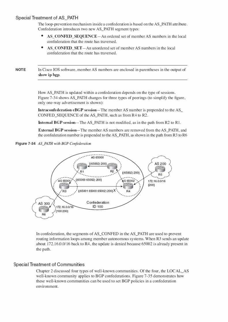
Confederation
As indicated in the previous section, route reflection solves the iBGP scalability issue byb relaxing the iBGP
advertisement rule for RRs. These routers can reflect routes between clients they serve and other iBGP
peers; thus, clients need to peer only with RRs. Confederation approaches the same issue from a different
angle. This section discusses various aspects of confederation and its design guidelines.
How Confederation Works
Confederation solves the full iBGP mesh issue by splitting a large AS into a number of smaller autonomous
systems, called member autonomous systems or subautonomous systems. Because eBGP sessions are used
among member autonomous systems, no full mesh is required. Within each member AS, however, the iBGP
full-mesh requirement still applies.
The eBGP session within a confederation is slightly different from a regular eBGP session. To differentiate
between the two, this type of eBGP session is called an intraconfederation eBGP session. When the session
is initially brought up, it behaves exactly like an eBGP session. In other words, no verification is made on
both peers to determine if the session is a true eBGP or confederation eBGP session. The difference comes
in when propagating


Solutions: Setting Proper IGP Metrics Within Confederations Because path selection does not consider
member AS numbers, solutions to this problem are similar to those provided for route reflection. The
following briefly describes each of the solutions:
• Use full iBGP mesh—As with route reflection, this solution might not be acceptable if confederation is
used in the first place to increase iBGP scalability.
• Enable always-compare-med—Because MEDs are not modified by member autonomous systems, the
same guidelines and caveats apply as for route reflection.
• Enable deterministic-MED comparison—It is almost always a good practice to enable deterministic
MED comparison, although there might be cases in which this solution alone does not solve the problem.
• Reset MEDs to 0s—This eliminates MED as a decision-maker. The same guidelines apply as for route
reflection.
• Use communities—Communities exchanged between external neighbors are primarily private community
values, so the same guidelines apply as for route reflection.
• Set proper IGP metrics—If the intra-member-AS metric is set lower than the intermember- AS, the intra-
member-AS path is preferred over the inter-member-AS paths, with all other higher-order comparisons
being equal. This stops the
Confederation Versus Route Reflection
This chapter introduced two approaches to solve the iBGP scalability issue—confederation and route
reflection. Each method has its strengths and weaknesses, so how do you determine which method to use
during a network design? This section helps you answer that question by comparing and contrasting the two
methods


Transit and Peering Overview
The focus so far has been on the ISP infrastructure and downstream connectivity for
customer connections. This section discusses upstream ISP connectivity to the rest of the Internet. There are
three primary types of upstream connectivity:
• Transit
• Peering—public and private
• ISP tiers and peering
The subject of upstream connectivity is one of the most political aspects of the ISP
business, as you’ll learn in the next sections.

Transit Connectivity Transit connectivity is the most common form of connectivity available to small-tomedium- sized ISPs.
Transit service essentially means buying full connectivity to the Internet from another ISP. An ISP sells
transit service to its end customers. A transit connection means that the upstream provider lets the customer
transit its network to reach any available destination on the Internet.
Peering
The term peering refers to both public and private peering. Peering in a general sense between two ISPs
means that reachability to that ISP and its direct customers is provided over that connection. If ISP 1 and ISP
2 initiate a peering connection, they can reach each other but not ISP 3 if it is not a customer of either ISP 1
or ISP 2. Essentially, peering involves the exchange of partial routes between the two peering ISPs. The cost
of peering is typically less than full transit service, because both ISPs peering expect to offload the traffic
passing between their customers from their transit links.
Public Peering
Public peering occurs at one of the public peering points, such as Network Access Points (NAPs),
Metropolitan Area Exchanges (MAEs), or Internet Exchange Points (IXPs). Typically, peering at a public
peering point is done over a broadcast medium, such as Fast Ethernet or Gigabit Ethernet. Several of the
major exchanges have started offering ATM service at the exchange points to provide quality of service
(QoS) guarantees. An ISP
Case Study 1: iBGP Full Mesh to Route Reflection Migration
Case Study 2: iBGP Full Mesh to Confederation Migration
Case Study 3: Route Reflection to Confederation Migration
Case Study 4: Confederation to Route Reflection Migration