Embed Size (px)
Citation preview

R o y a l VR o y a l VR o y a l VR o y a l VR o y a l V e n d o r s , I n c .e n d o r s , I n c .e n d o r s , I n c .e n d o r s , I n c .e n d o r s , I n c .
O p e r a t i o n a n d S e r v i c e M a n u a lO p e r a t i o n a n d S e r v i c e M a n u a lO p e r a t i o n a n d S e r v i c e M a n u a lO p e r a t i o n a n d S e r v i c e M a n u a lO p e r a t i o n a n d S e r v i c e M a n u a l
Merlin RBMerlin RBMerlin RBMerlin RBMerlin RBRoyal Vendors Red Bull VenderRoyal Vendors Red Bull VenderRoyal Vendors Red Bull VenderRoyal Vendors Red Bull VenderRoyal Vendors Red Bull Vender
Customer Service:+1 304 728 7056
Technical Service Fax: +1 304 725 6579Parts Fax: +1 304 725 4016
E-mail: [email protected]@royalvendors.com
Website: www.royalvendors.com
R
Manufactured by
Royal Vendors, Inc.Bardane Industrial Park426 Industrial BoulevardKearneysville WV 25430-2776 USA
230 VAC 50 Hz Models230 VAC 50 Hz Models230 VAC 50 Hz Models230 VAC 50 Hz Models230 VAC 50 Hz Models

Royal Vendors, Inc. • 426 Industrial Boulevard • Kearneysville WV 25430-2776 • USACustomer Service: +1 (304) 728-7056 • Fax +1 (304) 725-6579
E-mail: [email protected]@royalvendors.com
Website: www.royalvendors.com
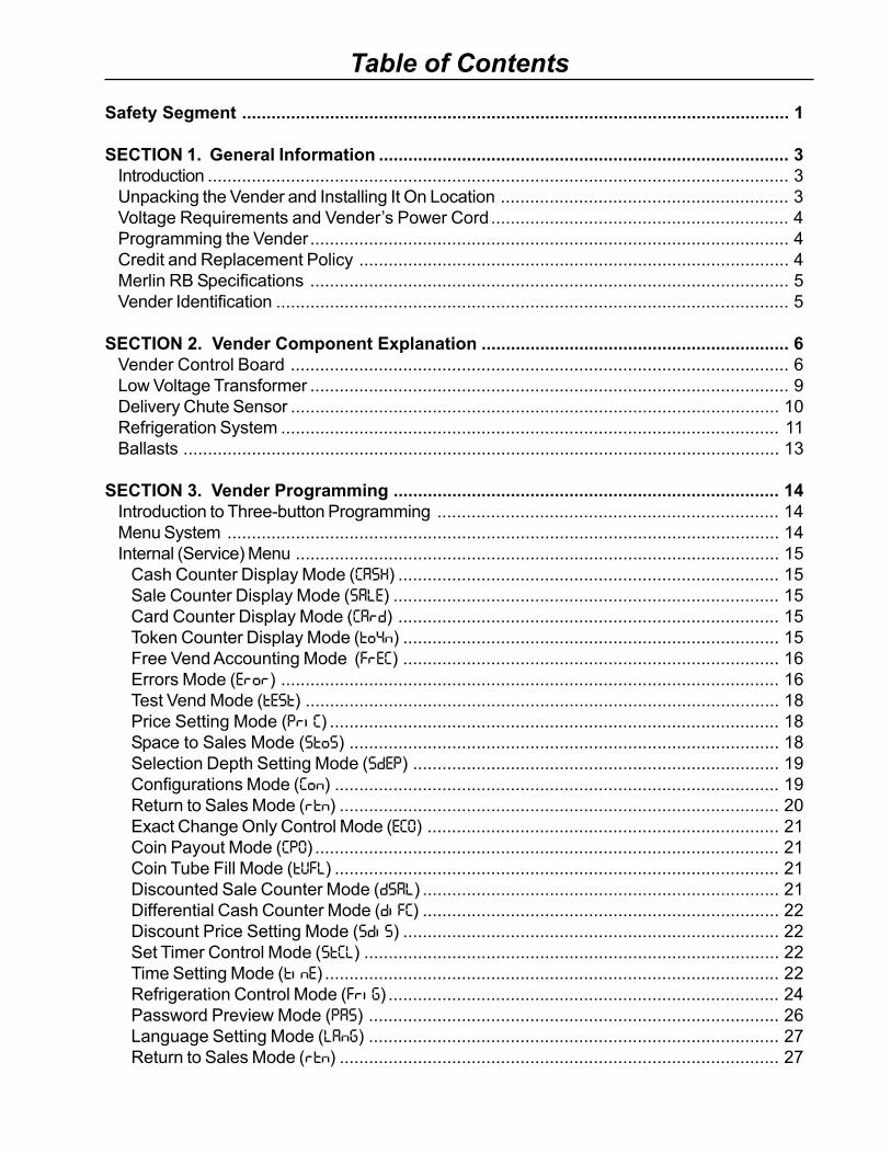
Table of Contents
Safety Segment ................................................................................................................ 1
SECTION 1. General Information .................................................................................... 3Introduction ....................................................................................................................... 3Unpacking the Vender and Installing It On Location ........................................................... 3Voltage Requirements and Vender’s Power Cord............................................................. 4Programming the Vender.................................................................................................. 4Credit and Replacement Policy ........................................................................................ 4Merlin RB Specifications .................................................................................................. 5Vender Identification ......................................................................................................... 5
SECTION 2. Vender Component Explanation ............................................................... 6Vender Control Board ...................................................................................................... 6Low Voltage Transformer .................................................................................................. 9Delivery Chute Sensor .................................................................................................... 10Refrigeration System ...................................................................................................... 11Ballasts .......................................................................................................................... 13
SECTION 3. Vender Programming ............................................................................... 14Introduction to Three-button Programming ...................................................................... 14Menu System ................................................................................................................. 14Internal (Service) Menu ................................................................................................... 15
Cash Counter Display Mode (CASH) .............................................................................. 15Sale Counter Display Mode (SALE) ............................................................................... 15Card Counter Display Mode (CArd) .............................................................................. 15Token Counter Display Mode (to4n) ............................................................................. 15Free Vend Accounting Mode (FrEC) ............................................................................. 16Errors Mode (Eror) ...................................................................................................... 16Test Vend Mode (tESt) ................................................................................................. 18Price Setting Mode (PriC) ............................................................................................ 18Space to Sales Mode (StoS) ........................................................................................ 18Selection Depth Setting Mode (SdEP) ........................................................................... 19Configurations Mode (Con) ........................................................................................... 19Return to Sales Mode (rtn) .......................................................................................... 20Exact Change Only Control Mode (ECO) ........................................................................ 21Coin Payout Mode (CPO) ............................................................................................... 21Coin Tube Fill Mode (tUFL) ........................................................................................... 21Discounted Sale Counter Mode (dSAL) ......................................................................... 21Differential Cash Counter Mode (diFC) ......................................................................... 22Discount Price Setting Mode (SdiS) ............................................................................. 22Set Timer Control Mode (StCL) ..................................................................................... 22Time Setting Mode (tinE) ............................................................................................. 22Refrigeration Control Mode (FriG) ................................................................................ 24Password Preview Mode (PAS) .................................................................................... 26Language Setting Mode (LAnG) .................................................................................... 27Return to Sales Mode (rtn) .......................................................................................... 27
Table of Contents
SECTION 4. Vend Cycle ................................................................................................ 28Stand-by Condition ......................................................................................................... 28Establishing Credit ......................................................................................................... 28Valid Selection ............................................................................................................... 28Vend Sequence .............................................................................................................. 28Product Delivery ............................................................................................................. 28Column Sequencing ....................................................................................................... 28Sold-Out ......................................................................................................................... 28Resetting Sold Out Selections ........................................................................................ 28
SECTION 5. Vender Maintenance ................................................................................. 29What to Clean................................................................................................................. 29What to Lubricate ........................................................................................................... 29Preventive Maintenance ................................................................................................. 29
SECTION 6. Vender Troubleshooting .......................................................................... 30Using the Vender’s Error Code System .......................................................................... 30Troubleshooting .............................................................................................................. 31Electronic Refrigeration Troubleshooting Flowchart ......................................................... 36
SECTION 7. Training Guide........................................................................................... 37
SECTION 8. Parts Catalogue ........................................................................................ 41Control Board and Wiring ............................................................................................... 41Door Rear ...................................................................................................................... 42Security Plate Assembly ................................................................................................. 43Vend Mechanism Assembly ............................................................................................ 44Inner Door Assembly ...................................................................................................... 45Refrigeration Section...................................................................................................... 46Door Front ...................................................................................................................... 47Miscellaneous Parts ....................................................................................................... 48
SECTION 9. Wiring Schematic ...................................................................................... 50
Merlin RB 230 VAC 50 Hz Vender Operation and Service ManualMerlin RB 230 VAC 50 Hz Vender Operation and Service ManualMerlin RB 230 VAC 50 Hz Vender Operation and Service ManualMerlin RB 230 VAC 50 Hz Vender Operation and Service ManualMerlin RB 230 VAC 50 Hz Vender Operation and Service Manual 1
Safety Segment
Safety SegmentROYAL VENDORS’ COMMITMENT TOSAFETY
Royal Vendors is committed to safety with all of ourproduct designs. We are committed to notifying theuser of a possible danger involving the improperhandling or maintenance of our venders. Theservicing of any electrical or mechanical deviceinvolves potential dangers, both to those servicingthe equipment and to users of the equipment. Thesedangers can occur because of improper mainte-nance or usage. The purpose of this safety segmentis to alert everyone servicing Royal equipment ofpotentially dangerous areas, and to provide basicsafety guidelines for proper upkeep.
The service manual contains various warnings thatshould be carefully read to minimise the risk ofpersonal injury. This manual also contains serviceinformation to insure that proper methods arefollowed to avoid damaging the vender or making itunsafe. It is also important to understand thesewarnings provide general guidance only. Royalcould not possibly know, evaluate, or advise of all ofthe conceivable ways in which service might bedone. Consequently, Royal cannot predict all of thepossible dangerous results. These outlined safetyprecautions are the basis for an effective safetyprogram. Use these safety measures, along with theservice bulletins, helpful hints and product specifica-tion sheets, when installing or servicing Royalequipment.
We recommend that persons servicing our equip-ment maintain a similar commitment to safety. Onlypersonnel properly trained should have accessto the interior of the vender. This will minimise thepotential dangers that are inherent in electrical andmechanical devices. Royal has no control over thevender once it leaves the premises. It is the owneror lessor’s responsibility to maintain the vender in asafe condition. See installation insert located in thecoin box of a new vender for proper installationprocedures and refer to the service manual forrecommended maintenance procedures. If you haveany questions, please contact the Technical ServiceDepartment at +1 304 728-7056.
SAFETY REGULATIONS
· Read the safety segment before installation orservice.
· Test for proper grounding before installing toreduce the risk of electrical shock and fire.
· Turn off or disconnect power cord from powersource before servicing.
· Only fully trained service technicians shouldservice vender when vender has power.
· Remove any product before moving a vender.· Use appropriate equipment when moving a
vender.· Always wear eye protection, and protect your
hands, face, and body when working near therefrigeration system.
· Use only authorised replacement parts.· Be aware of inherent dangers in rocking or tipping
a vender.
SECTION I: ELECTRICAL HAZARDSGENERAL ADVICE
Careless or improper handling of electrical circuitscan result in injury or death. Anyone installing,repairing, loading, opening, or otherwise servicing avender should be aware of this precaution. Apply allof the normal precautions when handling electricalcircuits, such as:
· Refrigeration servicing to be performed byqualified personnel only.
· Unplug the vender before servicing.· Replace electrical cords if there is any evidence
of fraying or other damage.· Keep all protective covers and earthing wires in
place.· Plug equipment into outlets that are properly
earthed and polarised (where applicable), andprotected with fuses or circuit breakers of thecorrect size.
· All electrical connections must be dry and free ofmoisture before applying power.
WARNING: ALWAYS TEST TO VERIFY PROPEREARTHING PRIOR TO INSTALLATION IN ORDERTO REDUCE THE RISK OF ELECTRICAL SHOCKAND FIRE.
Merlin RB 230 VAC 50 Hz Vender Operation and Service ManualMerlin RB 230 VAC 50 Hz Vender Operation and Service ManualMerlin RB 230 VAC 50 Hz Vender Operation and Service ManualMerlin RB 230 VAC 50 Hz Vender Operation and Service ManualMerlin RB 230 VAC 50 Hz Vender Operation and Service Manual2
Safety Segment
SECTION II: ELECTRICAL HAZARDSA. Servicing with Power OffFor maximum safety, unplug the power cord from thewall outlet before opening the vender door. This willremove power from the equipment and avoid electri-cal hazards. Service personnel should remain awareof possible hazards from hot components althoughelectrical power is off.
B. Servicing with Power OnSome service situations may require access withpower on. Only fully qualified service techniciansshould perform power-on servicing. Particularcaution is required in servicing assemblies thatcombine electrical power and mechanical movement.Sudden movement (to escape mechanical action)can result in contact with live circuits and vice versa.It is therefore important to maintain maximumclearances from both moving parts and live circuitswhen servicing.
WARNINGS:1. ONLY FULLY TRAINED PERSONNEL SHOULD
ACCOMPLISH SERVICING WITH POWER ON.SUCH SERVICE BY UNQUALIFIED INDIVIDU-ALS CAN BE DANGEROUS.
2. LIGHTING CIRCUITS CAN BE HAZARDOUS.ALWAYS DISCONNECT FROM POWER SUP-PLY BEFORE REPLACING A BULB OR SERVIC-ING THE VENDER IN THAT AREA.
3. NEVER USE A HOSE, PRESSURE WASHEROR ANY CLEANING METHOD THAT COULDWET ELECTRICAL COMPONENTS. SEECLEANING SECTION OF MANUAL FOR SUG-GESTED CLEANING METHODS. IF WATERCONTAMINATION OF ELECTRICAL COMPO-NENTS IS SUSPECTED, USE QUALIFIEDELECTRICAL TESTING EQUIPMENT AND TESTMETHODS TO ASSURE THAT VENDER IS NOTA HAZARD BEFORE APPLYING POWER FORANY REASON.
Merlin RB 230 VAC 50 Hz Vender Operation and Service ManualMerlin RB 230 VAC 50 Hz Vender Operation and Service ManualMerlin RB 230 VAC 50 Hz Vender Operation and Service ManualMerlin RB 230 VAC 50 Hz Vender Operation and Service ManualMerlin RB 230 VAC 50 Hz Vender Operation and Service Manual 3
Section 1. General Information and Setup
General InformationIntroductionThis manual contains installation, operation, andservice instructions for the Royal Vendors Merlin RB230 VAC 50 Hz vender. This manual also contains aparts catalogue and electrical schematic for theMerlin RB.
Through the Merlin RB’s flexibility, you will profit byusing the Multi-Pricing and Space-to-Sales features.As you will see later in the manual, there are otherfeatures, such as the ability to control vending byusing a built-in timer or by using an optional on / offkey switch. Like most electronic equipment, thecontrol board has the ability to control most items inthe vending machine. It manages the operation ofthe refrigeration system, and even the lightingsystem, with an optional kit. The Merlin RB utiliseshigh torque 24 volt DC vend motors. Testing hasproven these vend motors to be very strong andreliable.
2 3 0 V A C 5 0 H z
C A N V E N D E R
Unpacking the Vender andInstalling It On LocationUNWRAP THE VENDERUnwrap the vender and remove the padding. Checkfor any signs of damage. If the vender is damaged,contact the carrier immediately. They will instruct youon the procedure for filing a claim.
If the vender is being stored, remove the plasticstretch wrap, cardboard cover, and styrofoamcushioning first. The plastic stretch wrap andstyrofoam cushioning can adhere to the exterior ofthe vender over an extended period of time, damag-ing the vender’s finish.
Note: The vender’s keys are located in the coin cup.
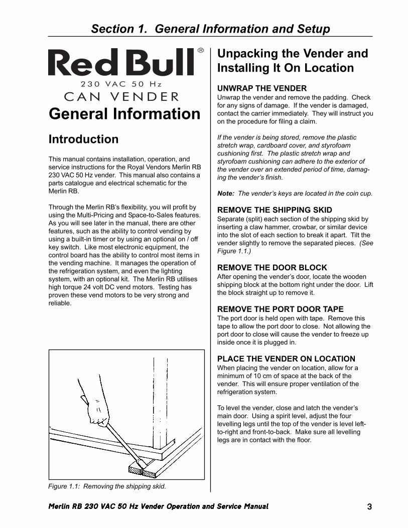
REMOVE THE SHIPPING SKIDSeparate (split) each section of the shipping skid byinserting a claw hammer, crowbar, or similar deviceinto the slot of each section to break it apart. Tilt thevender slightly to remove the separated pieces. (SeeFigure 1.1.)
REMOVE THE DOOR BLOCKAfter opening the vender’s door, locate the woodenshipping block at the bottom right under the door. Liftthe block straight up to remove it.
REMOVE THE PORT DOOR TAPEThe port door is held open with tape. Remove thistape to allow the port door to close. Not allowing theport door to close will cause the vender to freeze upinside once it is plugged in.
PLACE THE VENDER ON LOCATIONWhen placing the vender on location, allow for aminimum of 10 cm of space at the back of thevender. This will ensure proper ventilation of therefrigeration system.
To level the vender, close and latch the vender’smain door. Using a spirit level, adjust the fourlevelling legs until the top of the vender is level left-to-right and front-to-back. Make sure all levellinglegs are in contact with the floor.
Figure 1.1: Removing the shipping skid.
Merlin RB 230 VAC 50 Hz Vender Operation and Service ManualMerlin RB 230 VAC 50 Hz Vender Operation and Service ManualMerlin RB 230 VAC 50 Hz Vender Operation and Service ManualMerlin RB 230 VAC 50 Hz Vender Operation and Service ManualMerlin RB 230 VAC 50 Hz Vender Operation and Service Manual4
Voltage Requirements andVender’s Power CordThe Merlin RB vender is designed to operate at avoltage of 230 volts AC, 50 Hertz. It requires theminimum of a 7 amp service, and it should be on adedicated circuit. The service outlet voltage must notexceed 264 VAC or fall below 198 VAC.
The vender has a three-wire earthed cord. Thevender must be plugged into an earthed electricaloutlet to protect customers from electrical shock. Ifthe outlet is not equipped with an earthed socket,have one installed by a qualified electrician. Do notuse an extension cord, unless it has been authorisedby a certified electrician. Extension cords are notrecommended.
After plugging the vender’s power cord into the ACvoltage source, the following should be observed:
1. The fluorescent lights will come on;2. The refrigeration compressor will start to run after
approximately 5-7 minutes (with the door closed);and
3. The LED will light.
The control board is equipped with a battery backupfor use in the event of a power loss. The battery isused to retain important programming information,such as space-to-sales, prices, etc., so that it will notbe erased if power is lost or the vender is unplugged.
Programming the VenderAll programming of the vender is done in the ServiceMode. To enter the Service Mode, open the vender’smain door, and press and release the Service Modebutton, located on the controller board. For program-ming instructions, see the section entitled “VenderProgramming,” later in this book.
Section 1. General Information and Setup
Credit and ReplacementPolicyCREDITS OR REPLACEMENTS WILL BE ISSUEDON WARRANTY ITEMS IF THE PROPER PROCE-DURES ARE FOLLOWED:
1. Royal Vendors will pay shipping charges on allparts covered under this warranty, when trans-portation has been made the most economicalway. An ARS (Authorized Return Service) labelwill be sent with all warranty parts. This methodof shipping is preferred for returning parts toRoyal Vendors.
2. Credits will only be issued to warranty parts thathave been ordered in advance; not for partsordered as stock (NO EXCEPTIONS).
3. When ordering warranty parts in advance, pleasehave the full vender / unit serial number.
4. A copy of the Packing Slip, correct serial number,and complete Return Material Tag (provided withpart) are required for returning parts. Pleasecomplete the Return Material Tag, keeping thewhite copy for your records and returning theyellow tag with the attached part. Make sure youhave your company’s name, address, phonenumber, serial number, and model number alongwith a brief explanation of the problem.
5. If the item returned is not under warranty, it willbe sent back to you at your expense or it will bescrapped.
6. All warranty parts should be properly wrappedand packed securely to avoid further damage.Refrigeration units that are returned from thefield and have been tapped into, tampered with,not packaged properly, or have had the serialplate removed, will void the warranty.
7. If parts are not returned within 15 working days,the invoice will be due in full.
Merlin RB 230 VAC 50 Hz Vender Operation and Service ManualMerlin RB 230 VAC 50 Hz Vender Operation and Service ManualMerlin RB 230 VAC 50 Hz Vender Operation and Service ManualMerlin RB 230 VAC 50 Hz Vender Operation and Service ManualMerlin RB 230 VAC 50 Hz Vender Operation and Service Manual 5
Section 1. General Information and Setup
Merlin RB SpecificationsDimensions (372 cap.) .......... 183 cm H x 61 cm W x
91 cm DApproximate empty weight ... 231 kgOperating voltage ................. 230 VAC, 50 HzAmperage rating .................... 4 AmpCharge.................................. 0.18 kg R134aConstruction ......................... Steel cabinet, steel
doorConfiguration ........................ 3 selections, 4 columns
Vender IdentificationThe Merlin RB can be easily identified by taking noteof the following three items:
1. Vender serial plate - mounted on the exterior leftside of the vender door;
2. Refrigeration serial plate - mounted on the “kickplate” of the refrigeration unit; and
3. Control chip revision number - printed on a whitelabel affixed to the chip.
VENDER SERIAL PLATE
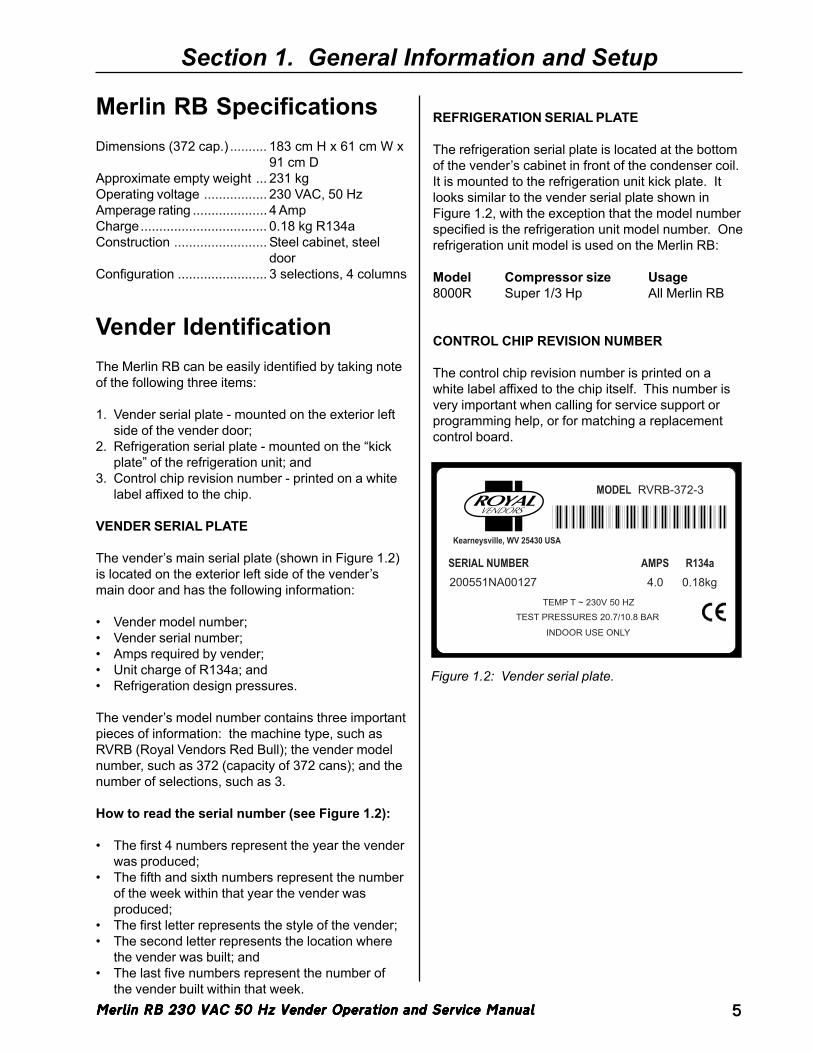
The vender’s main serial plate (shown in Figure 1.2)is located on the exterior left side of the vender’smain door and has the following information:
• Vender model number;• Vender serial number;• Amps required by vender;• Unit charge of R134a; and• Refrigeration design pressures.
The vender’s model number contains three importantpieces of information: the machine type, such asRVRB (Royal Vendors Red Bull); the vender modelnumber, such as 372 (capacity of 372 cans); and thenumber of selections, such as 3.
How to read the serial number (see Figure 1.2):
• The first 4 numbers represent the year the venderwas produced;
• The fifth and sixth numbers represent the numberof the week within that year the vender wasproduced;
• The first letter represents the style of the vender;• The second letter represents the location where
the vender was built; and• The last five numbers represent the number of
the vender built within that week.
REFRIGERATION SERIAL PLATE
The refrigeration serial plate is located at the bottomof the vender’s cabinet in front of the condenser coil.It is mounted to the refrigeration unit kick plate. Itlooks similar to the vender serial plate shown inFigure 1.2, with the exception that the model numberspecified is the refrigeration unit model number. Onerefrigeration unit model is used on the Merlin RB:
Model Compressor size Usage8000R Super 1/3 Hp All Merlin RB
CONTROL CHIP REVISION NUMBER
The control chip revision number is printed on awhite label affixed to the chip itself. This number isvery important when calling for service support orprogramming help, or for matching a replacementcontrol board.
Figure 1.2: Vender serial plate.
200551NA00127 4.0 0.18kgSERIAL NUMBER AMPS R134a
RVRB-372-3MODEL
Kearneysville, WV 25430 USA
TEMP T ~ 230V 50 HZTEST PRESSURES 20.7/10.8 BAR
INDOOR USE ONLY
Merlin RB 230 VAC 50 Hz Vender Operation and Service ManualMerlin RB 230 VAC 50 Hz Vender Operation and Service ManualMerlin RB 230 VAC 50 Hz Vender Operation and Service ManualMerlin RB 230 VAC 50 Hz Vender Operation and Service ManualMerlin RB 230 VAC 50 Hz Vender Operation and Service Manual6
Section 2. Vender Component Explanation
Vender ComponentExplanationVender Control Board(including pinouts)The control board is responsible for most venderoperations. It is located in the upper left corner ofthe inside of the door. The control board is protectedby a cover. Removing this cover will expose thecontrol boad, along with all wiring connections to theboard.
IDENTIFICATION: The Merlin RB control board canbe easily identified by noting the revision number ofthe EEPROM chip on the control board. The numberwill be printed on a white decal affixed to this chip.
OPERATION REQUIREMENTS: The control boardrequires approximately 24 volts AC from the lowvoltage transformer (described later in this section).This will allow the control board to function and tosupply power to all the vender’s components listedbelow.
OPERATION: Upon receiving the appropriatevoltage from the transformer, the control board willissue information to some components, receiveinformation from some components, and communi-cate both ways with some components.
• The control board issues instructions (and / orvoltage) to:- LED display- Vend motors (only when vend motors are to run)- Refrigeration relay.
• The control board receives information (and / orvoltage) from:- Select switches (logic level)- Door switch (logic level)- Delivery chute sensor- Temperature sensor.
• The control board communicates both ways with:- Coin mechanism- Bill validator (optional)- Card reader (optional)- Hand-held computer (optional).
CONTROL BOARD PINOUTS: The Merlin RBcontrol board has several electrical pinouts, a setupmode button, a delivery sensor adjustment trimpot, adelivery sensor adjustment indicator lamp, andvarious other electronic components (all of whichhave designated position codes). The followingsection outlines all the control board’s pinouts.
The word key refers to the small plastic insertplugged into a position of the connector. The pur-pose of the key is to prevent connecting the harness-ing backwards or upside-down. The keyed positionis a blank position within the pinout (no pin) in whicha key is inserted. Some pinouts may have severalblank positions with a key plugged into one or moreof the positions. You can use the key to determinewhich end of the pinout is Pin 1.
PRECAUTIONS TO TAKE WHEN WORKING WITHCONTROL BOARD
As with any printed circuit board, our electronics arevery sensitive to Electrostatic Discharge (ESD).Simply walking across a tile or carpeted floor cangenerate a range of 30,000 to 50,000 volts of elec-tricity. One ESD can be enough to seriously damageyour control board or at least weaken it enough thaterratic problems could occur in the future. Even adischarge surge under 100 to 200 volts is enough tocreate problems within the circuitry of the electronics.It is advised when storing the electronics that they bekept in anti-static bags, even if the electronics arethought to be defective. If a control board is thoughtto be defective and is really not, it soon will be afterbeing charged with ESD. The ideal preventionagainst ESD is to use anti-static conductive wriststraps which earth you to the machine before touch-ing the electronic boards. If it is not possible to usethese, at least earth yourself before handling theelectronic boards. Whatever method you use,always handle the electronic boards by the edges.Be careful not to touch the components on thecontrol board.
Merlin RB 230 VAC 50 Hz Vender Operation and Service ManualMerlin RB 230 VAC 50 Hz Vender Operation and Service ManualMerlin RB 230 VAC 50 Hz Vender Operation and Service ManualMerlin RB 230 VAC 50 Hz Vender Operation and Service ManualMerlin RB 230 VAC 50 Hz Vender Operation and Service Manual 7
Section 2. Vender Component Explanation
������ ��
��� � ���
�������� � �����
�����
��
�����
��
� �
����� ���
�������� �����
��
�������� ��������������������
�����
��
���������
���
����������
���
���������
��
�� ���
���
���
��
���
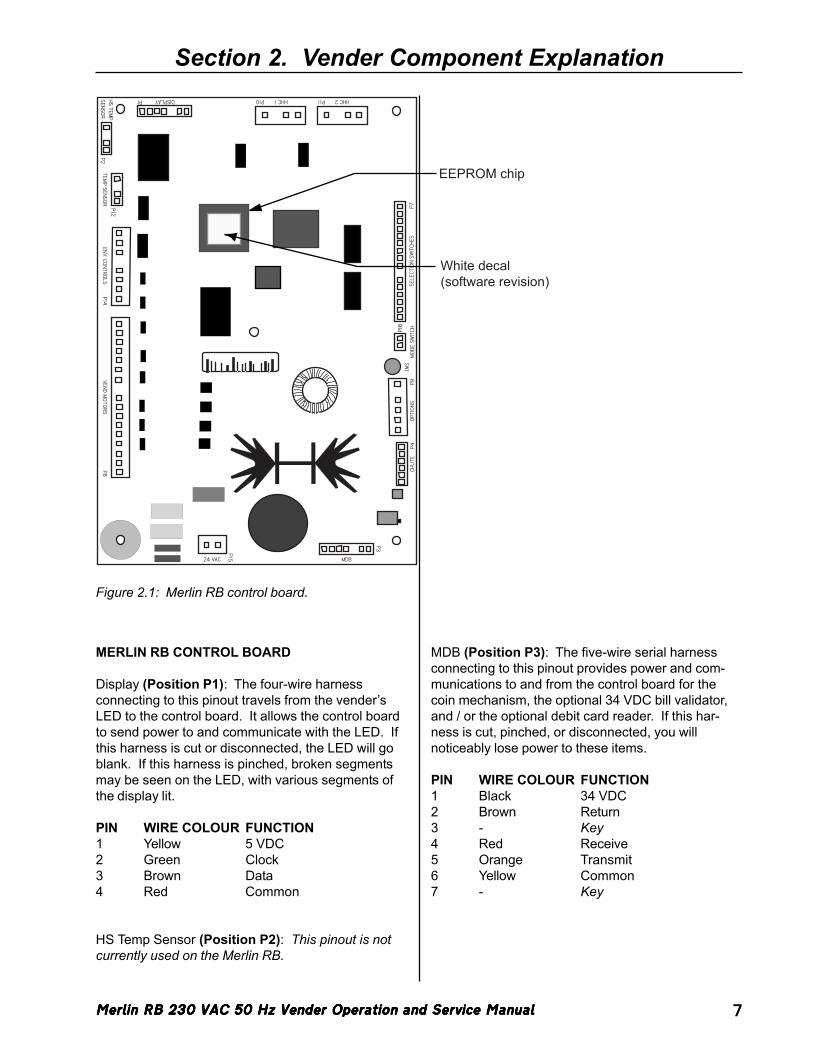
Figure 2.1: Merlin RB control board.
MERLIN RB CONTROL BOARD
Display (Position P1): The four-wire harnessconnecting to this pinout travels from the vender’sLED to the control board. It allows the control boardto send power to and communicate with the LED. Ifthis harness is cut or disconnected, the LED will goblank. If this harness is pinched, broken segmentsmay be seen on the LED, with various segments ofthe display lit.
PIN WIRE COLOUR FUNCTION1 Yellow 5 VDC2 Green Clock3 Brown Data4 Red Common
HS Temp Sensor (Position P2): This pinout is notcurrently used on the Merlin RB.
MDB (Position P3): The five-wire serial harnessconnecting to this pinout provides power and com-munications to and from the control board for thecoin mechanism, the optional 34 VDC bill validator,and / or the optional debit card reader. If this har-ness is cut, pinched, or disconnected, you willnoticeably lose power to these items.
PIN WIRE COLOUR FUNCTION1 Black 34 VDC2 Brown Return3 - Key4 Red Receive5 Orange Transmit6 Yellow Common7 - Key
Merlin RB 230 VAC 50 Hz Vender Operation and Service ManualMerlin RB 230 VAC 50 Hz Vender Operation and Service ManualMerlin RB 230 VAC 50 Hz Vender Operation and Service ManualMerlin RB 230 VAC 50 Hz Vender Operation and Service ManualMerlin RB 230 VAC 50 Hz Vender Operation and Service Manual8
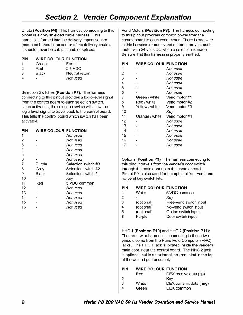
Chute (Position P4): The harness connecting to thispinout is a grey shielded cable harness. Thisharness is formed into the delivery impact sensor(mounted beneath the center of the delivery chute).It should never be cut, pinched, or spliced.
PIN WIRE COLOUR FUNCTION1 Green Earth2 Red 2.5 VDC3 Black Neutral return4 - Not used
Selection Switches (Position P7): The harnessconnecting to this pinout provides a logic-level signalfrom the control board to each selection switch.Upon activation, the selection switch will allow thelogic-level signal to travel back to the control board.This tells the control board which switch has beenactivated.
PIN WIRE COLOUR FUNCTION1 - Not used2 - Not used3 - Not used4 - Not used5 - Not used6 - Not used7 Purple Selection switch #38 Grey Selection switch #29 Black Selection switch #110 - Key11 Red 5 VDC common12 - Not used13 - Not used14 - Not used15 - Not used16 - Not used
Section 2. Vender Component ExplanationVend Motors (Position P8): The harness connectingto this pinout provides common power from thecontrol board to each vend motor. There is one wirein this harness for each vend motor to provide eachmotor with 24 volts DC when a selection is made.Be sure that this harness is properly earthed.
PIN WIRE COLOUR FUNCTION1 - Not used2 - Not used3 - Not used4 - Not used5 - Not used6 - Not used7 Green / white Vend motor #18 Red / white Vend motor #29 Yellow / white Vend motor #310 - Key11 Orange / white Vend motor #412 - Not used13 - Not used14 - Not used15 - Not used16 - Not used17 - Not used
Options (Position P9): The harness connecting tothis pinout travels from the vender’s door switchthrough the main door up to the control board.Pinout P9 is also used for the optional free-vend andno-vend key switch kits.
PIN WIRE COLOUR FUNCTION1 White 5 VDC common2 - Key3 (optional) Free-vend switch input4 (optional) No-vend switch input5 (optional) Option switch input6 Purple Door switch input
HHC 1 (Position P10) and HHC 2 (Position P11):The three-wire harnesses connecting to these twopinouts come from the Hand Held Computer (HHC)jacks. The HHC 1 jack is located inside the vender’smain door, near the control board. The HHC 2 jackis optional, but is an external jack mounted in the topof the welded port assembly.
PIN WIRE COLOUR FUNCTION1 Red DEX receive data (tip)2 - Key3 White DEX transmit data (ring)4 Green DEX common
Merlin RB 230 VAC 50 Hz Vender Operation and Service ManualMerlin RB 230 VAC 50 Hz Vender Operation and Service ManualMerlin RB 230 VAC 50 Hz Vender Operation and Service ManualMerlin RB 230 VAC 50 Hz Vender Operation and Service ManualMerlin RB 230 VAC 50 Hz Vender Operation and Service Manual 9
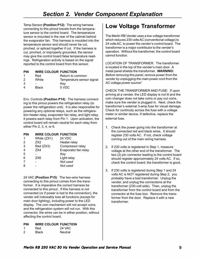
Section 2. Vender Component ExplanationTemp Sensor (Position P12): The wiring harnessconnecting to this pinout travels from the tempera-ture sensor to the control board. The temperaturesensor is mounted in the rear of the cabinet behindthe evaporator fan. This harness is moulded into thetemperature sensor and should never be cut,pinched, or spliced together if cut. If the harness iscut, pinched, or improperly grounded, the sensormay give the control board false temperature read-ings. Refrigeration activity is based on the signalreported to the control board from this sensor.
PIN WIRE COLOUR FUNCTION1 Red Return to common2 White Temperature sensor signal3 - Key4 Black 5 VDC
Env. Controls (Position P14): The harness connect-ing to this pinout powers the refrigeration relay (topower the refrigeration unit). It is also responsible forpowering any optional relays, such as the refrigera-tion heater relay, evaporator fan relay, and light relay.It powers each relay from Pin 1. Upon activation, thecontrol board will remain neutral for each relay fromeither Pin 2, 3, 4, or 6.
PIN WIRE COLOUR FUNCTION1 White (ZX1) 24 VDC2 ZX2 Heater relay3 Red (ZX3) Compressor relay4 ZX4 Evaporator fan relay5 - Key6 ZX6 Light relay7 - Not used8 - Not used
24 VAC (Position P15): The two-wire harnessconnecting to this pinout comes from the trans-former. It is imperative the correct harness beconnected to this pinout. If this harness is notconnected (or if power is lost to the connection), thevender will noticeably lose all functions (except formain door lighting), including power to the LEDdisplay. The coin mechanism will not accept coins,and the refrigeration system will not run. With thisconnector, the wires can be in either position, withoutaffecting the control board.
PIN WIRE COLOUR FUNCTION1 Red 24 VAC2 Black Neutral
Low Voltage TransformerThe Merlin RB Vender uses a low voltage transformerwhich reduces 230 volts AC (conventional voltage) to24 volts AC, to power the vender’s control board. Thetransformer is a major contributor to the vender’soperation. Without the transformer, the control boardcannot function.
LOCATION OF TRANSFORMER: The transformeris located in the top of the vender’s main door. Ametal panel shields the transformer. WARNING:Before removing this panel, remove power from thevender by unplugging the main power cord from theAC voltage power source!
CHECK THE TRANSFORMER AND FUSE: If uponarriving at a vender, the LED display is not lit and thecoin changer does not take coins or pay out coins,make sure the vender is plugged in. Next, check thetransformer’s external 3-amp fuse for visual damage.Check for continuity across the fuse with a voltagemeter or similar device. If defective, replace theexternal fuse.
1. Check the power going into the transformer atthe connected red and black wires. It shouldregister 230 volts AC. If not, check voltagecoming out of the main wiring harness.
2. If 230 volts is registered in Step 1, measurevoltage at the other end of the transformer. Thetwo (2) pin connector leading to the control boardshould register approximately 24 volts AC. If so,check the control board; the transformer is good.
3. If 230 volts is registered during Step 1 and 24volts AC is NOT registered during Step 2, youprobably have a bad transformer. Unplug thevender, and unplug the connections at thetransformer (230-volt side). Then, unplug thetransformer from the control board and from theconnector at the fuse box. Remove the trans-former from the door. Replace it with a newtransformer.
Merlin RB 230 VAC 50 Hz Vender Operation and Service ManualMerlin RB 230 VAC 50 Hz Vender Operation and Service ManualMerlin RB 230 VAC 50 Hz Vender Operation and Service ManualMerlin RB 230 VAC 50 Hz Vender Operation and Service ManualMerlin RB 230 VAC 50 Hz Vender Operation and Service Manual10
Section 2. Vender Component Explanation
Delivery Chute SensorADJUSTMENT: Located to the left of the controlboard’s chute sensor connector is the sensor adjust-ment trimpot, which includes an adjustment screw.The trimpot is used to adjust and fine tune thesensor. It is capable of turning both clockwise andanticlockwise. Located to the right of the trimpot isthe sensor adjustment LED indicator light. Theindicator light is mainly used to aid in adjusting thesensor but can also be used to test its operationduring product impact.
1. Turn the adjustment screw clockwise until theindicator light comes on.
2. Turn the screw anticlockwise until the light justgoes out.
3. Continue to turn the screw anticlockwise two (2)turns. Note: Slight adjustments may be neededoutside the factory set one and a half turns.Turning the adjustment screw clockwise makesthe sensor more sensitive and anticlockwisemakes it less sensitive. Test vend after every ¼turn.
For multiple vending from all columns, make sure thesensor is adjusted to the factory specifications aslisted above. Next, turn the adjustment screwclockwise ¼ turn to increase sensitivity. Test vendcolumns 1 and 4, and watch light on the board for agood on and off flash. If still multiple vending, turnthe adjustment screw an additional ¼ turn clockwiseuntil proper adjustment is made.
For dry vending (cancelled credit with no productdelivery) from all columns, make sure the sensor isadjusted to the factory specifications as listed above.Next, turn the adjustment screw anticlockwise ¼ turnto decrease sensitivity. Test vend all columns. If stilldry vending, turn the adjustment screw an additional¼ turn anticlockwise until proper adjustment is made.
TESTING THE DELIVERY CHUTE SENSOR: Makesure the vender is plugged in and the controller haspower (the LED display on the front of the vender willbe lit and the coin mechanism will accept coins).The sensor indicator lamp will blink upon impact onthe delivery chute. Lightly tap the chute with a tool oryour fist to simulate a can drop.
1. Locate the sensor adjustment indicator lamp onthe bottom left of the vender’s control board.Under normal conditions (as in stand-by), thelamp should be off.
2. Test the sensor by vending from columns 1 and4 while watching the control board’s sensoradjustment indicator lamp. The light should blinksolidly upon impact. If not, turn the adjustmentscrew clockwise in ¼-turn increments (to in-crease the sensitivity), and test after each turn.If the indicator lamp still does not light, turn theadjustment screw clockwise for many turns. Ifthe indicator lamp does not light, change thesensor (assuming the control board has powerand is working).
3. If the sensor adjustment indicator lamp lightsproperly during Step 2, change the control board.
4. Test the sensor by hitting the center of thedelivery chute while watching the control board’ssensor adjustment indicator lamp. The lightshould blink solidly upon impact.
Merlin RB 230 VAC 50 Hz Vender Operation and Service ManualMerlin RB 230 VAC 50 Hz Vender Operation and Service ManualMerlin RB 230 VAC 50 Hz Vender Operation and Service ManualMerlin RB 230 VAC 50 Hz Vender Operation and Service ManualMerlin RB 230 VAC 50 Hz Vender Operation and Service Manual 11
Section 2. Vender Component Explanation
Refrigeration SystemYour vender’s refrigeration system comes as acompletely sealed unit and should never be cutor tapped into, or the warranty will be voided.
IDENTIFICATION: The refrigeration unit is respon-sible for the cooling of the sealed cabinet and theproducts loaded within it. The refrigeration unit’sbase plate (compressor, condenser coils and con-denser fan motor), are mounted in the bottom(warm) section of the vender’s cabinet. The heatexchange or suction line extends into the upper(cold) section of the vender’s cabinet, where theevaporator coil is mounted in front of the evaporatorfan motor.
OPERATION REQUIREMENTS: The refrigerationsystem requires 230 volts AC from the main wiringharness for it to operate. The main wiring harnesswill get its voltage for the unit from the refrigerationrelay.
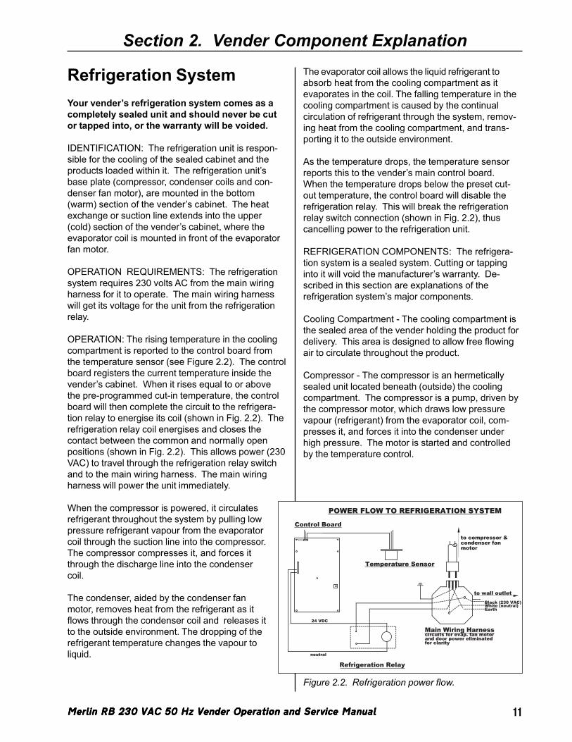
OPERATION: The rising temperature in the coolingcompartment is reported to the control board fromthe temperature sensor (see Figure 2.2). The controlboard registers the current temperature inside thevender’s cabinet. When it rises equal to or abovethe pre-programmed cut-in temperature, the controlboard will then complete the circuit to the refrigera-tion relay to energise its coil (shown in Fig. 2.2). Therefrigeration relay coil energises and closes thecontact between the common and normally openpositions (shown in Fig. 2.2). This allows power (230VAC) to travel through the refrigeration relay switchand to the main wiring harness. The main wiringharness will power the unit immediately.
When the compressor is powered, it circulatesrefrigerant throughout the system by pulling lowpressure refrigerant vapour from the evaporatorcoil through the suction line into the compressor.The compressor compresses it, and forces itthrough the discharge line into the condensercoil.
The condenser, aided by the condenser fanmotor, removes heat from the refrigerant as itflows through the condenser coil and releases itto the outside environment. The dropping of therefrigerant temperature changes the vapour toliquid.
The evaporator coil allows the liquid refrigerant toabsorb heat from the cooling compartment as itevaporates in the coil. The falling temperature in thecooling compartment is caused by the continualcirculation of refrigerant through the system, remov-ing heat from the cooling compartment, and trans-porting it to the outside environment.
As the temperature drops, the temperature sensorreports this to the vender’s main control board.When the temperature drops below the preset cut-out temperature, the control board will disable therefrigeration relay. This will break the refrigerationrelay switch connection (shown in Fig. 2.2), thuscancelling power to the refrigeration unit.
REFRIGERATION COMPONENTS: The refrigera-tion system is a sealed system. Cutting or tappinginto it will void the manufacturer’s warranty. De-scribed in this section are explanations of therefrigeration system’s major components.
Cooling Compartment - The cooling compartment isthe sealed area of the vender holding the product fordelivery. This area is designed to allow free flowingair to circulate throughout the product.
Compressor - The compressor is an hermeticallysealed unit located beneath (outside) the coolingcompartment. The compressor is a pump, driven bythe compressor motor, which draws low pressurevapour (refrigerant) from the evaporator coil, com-presses it, and forces it into the condenser underhigh pressure. The motor is started and controlledby the temperature control.
Main Wiring Harnesscircuits for evap. fan motorand door power eliminatedfor clarity
Refrigeration Relay
to wall outletBlack (230 VAC)White (neutral)Earth
Control Board
Temperature Sensor
to compressor &condenser fan motor
24 VDC
neutral
POWER FLOW TO REFRIGERATION SYSTEM
Figure 2.2. Refrigeration power flow.
Merlin RB 230 VAC 50 Hz Vender Operation and Service ManualMerlin RB 230 VAC 50 Hz Vender Operation and Service ManualMerlin RB 230 VAC 50 Hz Vender Operation and Service ManualMerlin RB 230 VAC 50 Hz Vender Operation and Service ManualMerlin RB 230 VAC 50 Hz Vender Operation and Service Manual12
Section 2. Vender Component Explanation
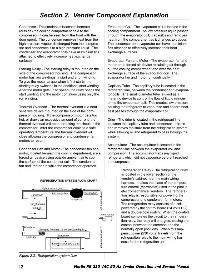
Figure 2.3. Refrigeration system flow.
Accumulator
Evaporator
Condenser
Compressor
Capillary
Low pressure gas
Low pressure gas
Changing from high to low pressure liquid
Liquid changing to a gas
Discharge line
Filter/Drier
Gas changing
to liquid
REFRIGERATION SYSTEM FLOW CHART
Suction line
High pressure gas
Condenser - The condenser is located beneath(outside) the cooling compartment next to thecompressor (it can be seen from the front with thedoor open). The condenser removes heat from thehigh pressure vapour discharged from the compres-sor and condenses it to a high pressure liquid. Thecondenser and evaporator coils have aluminium finsattached to effectively increase heat exchangesurfaces.
Starting Relay - The starting relay is mounted on theside of the compressor housing. The compressormotor has two windings: a start and a run winding.To give the motor torque when it first starts, thestarting relay switches in the additional start winding.After the motor gets up to speed, the relay opens thestart winding and the motor continues using only therun winding.
Thermal Overload - The thermal overload is a heatsensitive device mounted on the side of the com-pressor housing. If the compressor motor gets toohot, or draws an excessive amount of current, thethermal overload will open, breaking the circuit to thecompressor. After the compressor cools to a safeoperating temperature, the thermal overload willclose allowing the compressor and condenser fanmotors to restart.
Condenser Fan and Motor - The condenser fan andmotor, located beneath the cooling department, are aforced air device using outside ambient air to coolthe surface of the condenser coil. The condenserfan and motor run while the compressor operates.
Evaporator Coil - The evaporator coil is located in thecooling compartment. As low pressure liquid passesthrough the evaporator coil, it absorbs and removesheat from the compartment as it changes to vapour.The condenser and evaporator coil have aluminiumfins attached to effectively increase their heatexchange surfaces.
Evaporator Fan and Motor - The evaporator fan andmotor are a forced air device circulating air through-out the cooling compartment and over the heatexchange surface of the evaporator coil. Theevaporator fan and motor run continually.
Capillary Tube - The capillary tube is located in therefrigerant line, between the condenser and evapora-tor coils. The small diameter tube is used as ametering device to control the flow of liquid refriger-ant to the evaporator coil. This creates low pressurecausing the refrigerant to vapourise and absorb heatas it passes through the evaporator coil.
Drier - The drier is located in the refrigerant linebetween the capillary tube and condenser. It trapsand removes moisture from the refrigeration systemwhile allowing oil and refrigerant to pass through thesystem.
Accumulator - The accumulator is located in therefrigerant line between the evaporator coil andcompressor. The accumulator traps any liquidrefrigerant which did not vapourise before it reachedthe compressor.
Refrigeration Relay - The refrigeration relayis located in the lower section of thevender’s cabinet near the main wiringharness. It takes the place of the tempera-ture control (thermostat) used in the past inelectromechanical venders. The refrigera-tion relay is responsible for powering thecompressor and condenser fan motors.The refrigeration relay consists of a coilpowered by the control board (24 volts DC)and a double-pole switch. When the controlboard completes the circuit to the refrigera-tion relay, the relay will energise, closing thecontact between the common and thenormally open positions. When this hap-pens, power (230 volts) travels from therefrigeration relay to the main wiring har-ness for the refrigeration unit.
Merlin RB 230 VAC 50 Hz Vender Operation and Service ManualMerlin RB 230 VAC 50 Hz Vender Operation and Service ManualMerlin RB 230 VAC 50 Hz Vender Operation and Service ManualMerlin RB 230 VAC 50 Hz Vender Operation and Service ManualMerlin RB 230 VAC 50 Hz Vender Operation and Service Manual 13
Section 2. Vender Component ExplanationREFRIGERATION CYCLE
1. The rising temperature in the cooling compart-ment is reported to the control board through thetemperature sensor.
2. The control board registers the current tempera-ture inside the vender’s cabinet. When it risesequal to or above the pre-programmed cut-intemperature, the control board will complete thecircuit to the refrigeration relay to energise itscoil.
3. The refrigeration relay coil closes the contactbetween the common and normally open posi-tions allowing 230 volts to travel to the mainwiring harness to start the compressor.
4. The compressor circulates refrigerant throughoutthe system by pulling low pressure refrigerantvapour from the evaporator coil, compressing it,and forcing it into the condenser. The con-denser, aided by the condenser fan motor,removes heat from the refrigerant as it flowsthrough the condenser and releases it to theoutside environment. The dropping of therefrigerant temperature changes the vapour toliquid.
5. The evaporator coil allows the liquid refrigerantto absorb heat from the cooling compartment asit evaporates in the coil.
6. The falling temperature in the cooling compart-ment is caused by the continual circulation ofrefrigerant through the system, removing heatfrom the cooling compartment and transporting itto the outside environment. When the tempera-ture drops, the temperature sensor reports this tothe vender’s control board.
7. When the temperature drops below the presetcut-out temperature, the control board willdisable the refrigeration relay, thus killing powerto the refrigeration unit.
BallastsThe ballasts act as transformers to convert conven-tional voltage (230 VAC) to a higher voltage requiredto energise the vender’s fluorescent lights. Theballasts are located inside the vender’s door, behind ametal panel. To remove the ballasts from the door,use a Phillips (cross) screwdriver to remove thescrews that mount the ballasts to the door chassis.
WARNING: Before removing theballasts, remove power from thevender by unplugging the mainpower cord from the AC voltagepower source!
Note: Power to the ballasts is controlled by a relay,which is in turn controlled by the logic of the vender’scontrol board. See SECTION 3: VENDER PRO-GRAMMING for information on energising this relaythrough the service menu for troubleshooting pur-poses.
Merlin RB 230 VAC 50 Hz Vender Operation and Service ManualMerlin RB 230 VAC 50 Hz Vender Operation and Service ManualMerlin RB 230 VAC 50 Hz Vender Operation and Service ManualMerlin RB 230 VAC 50 Hz Vender Operation and Service ManualMerlin RB 230 VAC 50 Hz Vender Operation and Service Manual14
Section 3. Vender Programming
Vender ProgrammingIntroduction to Three-button ProgrammingIt is very important that your vender is programmedproperly. All programming of the vender options isdone in the Service Mode. To enter the ServiceMode, open the vender door, and press and releasethe blue service mode button that is located on thecontroller board.
The first three selection switches are used to navi-gate through the service routines as follows:
Button Meaning Usage1 UP Increase, next, up2 DOWN Decrease, previous, down3 ENTER (Press
and releasequickly) Enter, accept, save
3 EXIT (Pressand hold fortwo seconds) Escape, cancel, exit
The controller will automatically return to the SalesMode if:
• No response from the selection switches isreceived for approximately five minutes;
• The service mode button is pressed a secondtime;
• The Return to Sales mode is activated; or• The door is actually closed.
If credit exists, the credit amount will be displayedafter returning to the Sales Mode.
Menu SystemWhen programming, you must first use the program-ming buttons listed above to manoeuvre throughmenus and sub-menus before you will be allowed toaccomplish your task. Each menu consists ofvarious items, or modes, such as the Price SettingMode or the Space to Sales Mode. There are twodifferent internal menus available.
1. INTERNAL (Service) MENU: This menu isavailable only with the vender’s main door open.It is accessed upon pressing the control board’smode button.
2. OPTIONAL MENU: This menu is available whenConfiguration 2 is set to “1”.
Note: Programming flowchart located in rear ofmanual.
Merlin RB 230 VAC 50 Hz Vender Operation and Service ManualMerlin RB 230 VAC 50 Hz Vender Operation and Service ManualMerlin RB 230 VAC 50 Hz Vender Operation and Service ManualMerlin RB 230 VAC 50 Hz Vender Operation and Service ManualMerlin RB 230 VAC 50 Hz Vender Operation and Service Manual 15
Section 3. Vender Programming
Internal (Service) MenuOpening the vender’s main door and pressing thecontrol board’s service mode button will allow entryinto the Internal (Service) Menu. This sectionoutlines all the menu items.
Cash Counter Display ModeIf <enter> is pressed at the “CASH”prompt, the controller will enter the
non-resettable cash display mode by displaying“CASH” / “XXXX” / “XX.XX,” where the X’s willrepresent total cash over the life of the vender’scontrol board. A decimal point will be displayed inthe appropriate position with the lower four digits. Ifthe cash amount is less than five digits long, theupper four-digit set is not displayed. Using <up> or<down> will cycle through each selection as “CLNN”/ “XXXX” / “XX.XX,” where the N’s represent theappropriate selection number and the X’s representthe resettable cash count for that selection. If <exit>is pressed at any time during this operation, thecontroller will return to the code level. Press the<up> button to proceed to the next prompt, “SALE.”
CLEARING INDIVIDUAL COUNTERS: If theConfigurations Mode is set to allow the individualcounters to be reset, the individual counters will bereset upon reading at least one of them and closingthe vender’s main door.
Sale Counter Display ModeIf <enter> is pressed at the “SALE”prompt, the controller will enter thenon-resettable vend display mode by
displaying “SALE” / “XXXX” / “XXXX,” where the X’swill represent total number of all paid vends over thelife of the vender’s control board. If the sales amountis less than five digits long, the upper four-digit set isnot displayed. Using <up> or <down> will cyclethrough each selection as “SLNN” / “XXXX” /“XXXX,” where the N’s represent the appropriateselection number and the X’s represent theresettable vend count for that selection. If <exit> ispressed at any time during this operation, thecontroller will return to the code level. Press the<up> button to proceed to the next prompt, “CArd.”
CLEARING INDIVIDUAL COUNTERS: If theConfigurations Mode is set to allow the individualcounters to be reset, the individual counters will bereset upon reading at least one of them and closingthe vender’s main door.
CASH
SALE
Card Counter Display ModeIf <enter> is pressed at the “CArd”prompt, the controller will enter the
card counter display mode by displaying “CASH” /“XXXX” / “XX.XX,” where the X’s represent the cashequivalent of the card-paid vends over the life of thevender’s control board. A decimal point will bedisplayed in the appropriate position with the lowerfour digits. If the cash amount is less than five digitslong, the upper four-digit set is not displayed. Using<up> or <down> will cycle to the card vend count bydisplaying “SALE” / “XXXX” / “XXXX,” where the X’srepresent the number of card-paid vends over the lifeof the vender’s control board. If <exit> is pressed atany time during this operation, the controller willreturn to the code level. Press the <up> button toproceed to the next prompt, “toKn.”
Token Counter Display ModeIf <enter> is pressed at the “toKn”prompt, the controller will enter the
token counter display mode by displaying “CASH” /“XXXX” / “XX.XX,” where the X’s represent the cashequivalent of the token-paid vends over the life of thevender’s control board. A decimal point will bedisplayed in the appropriate position with the lowerfour digits. If the cash amount is less than five digitslong, the upper four-digit set is not displayed. Using<up> or <down> will cycle to the token vend count bydisplaying “SALE” / “XXXX” / “XXXX,” where the X’srepresent the number of token-paid vends over thelife of the vender’s control board. If <exit> is pressedat any time during this operation, the controller willreturn to the code level. Press the <up> button toproceed to the next prompt, “FrEC.”
CArd
to4n
Merlin RB 230 VAC 50 Hz Vender Operation and Service ManualMerlin RB 230 VAC 50 Hz Vender Operation and Service ManualMerlin RB 230 VAC 50 Hz Vender Operation and Service ManualMerlin RB 230 VAC 50 Hz Vender Operation and Service ManualMerlin RB 230 VAC 50 Hz Vender Operation and Service Manual16
Free Vend Accounting ModeIf <enter> is pressed at the “FrEC”prompt, the controller will enter the
first of three sub-menus, “CASH.” Pressing <up> or<down> will cycle through each of the other two sub-menus, “SALE” and “CoSt.” In this menu, free vend-related fields include all free and zero-priced vends.
If <enter> is pressed at the “CASH” prompt, thecontroller will enter the cash value display mode bydisplaying “CASH” / “XXXX” / “XX.XX,” where the X’srepresent the equivalent free-vend cash valuereceived over the life of the vender’s control board. Adecimal point is displayed in the appropriate positionwith the lower four digits. If the cash amount is lessthan five digits long, the upper four digits will not bedisplayed.
Using <up> or <down> will cycle through eachselection as “SLNN” / “XXXX” / “XX.XX,” where theN’s represent the appropriate selection number andthe X’s represent the resettable value of free vends.If <exit> is pressed at any time during this operation,the controller will return to the “FrEC” prompt.
If <enter> is pressed at the “SALE” prompt, thecontroller will enter the free vend counter displaymode by displaying “SALE” / “XXXX” / “XXXX,”where the X’s represent the number of all free vendsover the life of the vender’s control board. If thesales amount is less than five digits, the upper fourdigits will not be displayed.
Using <up> or <down> will cycle through eachselection as “SLNN” / “XXXX” / “XXXX,” where theN’s represent the appropriate selection number andthe X’s represent the resettable number of freevends. If <exit> is pressed at any time during thisoperation, the controller will return to the “FrEC”prompt.
If <enter> is pressed at the “CoSt” prompt, thecontroller will enter the free vend equivalent costdisplay mode by displaying “SLNN” / “XX.XX,” wherethe X’s represent the last saved price that is not00.00 for that selection. A decimal point will bedisplayed in the appropriate position. Using <up> or<down> will cycle through each selection. If <exit> ispressed at any time during this operation, thecontroller will return to the “FrEC” prompt. From“FrEC,” use <up> to proceed to the next prompt,“Eror.”
FrEC
Section 3. Vender Programming
Errors ModeIf <enter> is pressed at the “Eror”prompt, the controller will enter the
error display mode. If no errors have occurred sincethe last error reset, the display will show “nonE.” Ifan error has been detected since the last error reset,the display will show the first summary error codethat has occurred, such as “CHAr,” which wouldindicate a changer error. Pressing <up> or <down>will cycle through all of the summary error codes thatare present. If <enter> is pressed at the summaryerror code, the controller will display the detailederror code beneath that summary code (see belowfor error codes). Pressing <up> or <down> at thispoint will cycle through all the detailed error codesthat are present beneath the summary code. If<exit> is pressed at any time during this operation,the controller will return to the “Eror” prompt. Use<up> to proceed to the next prompt, “tESt.”
If <up> or <down> is pressed and held for twoseconds during the display of any error detail code,that error will be cleared. If other errors exist that fallunder the currently accessed detail type, the nexterror will now be displayed. If no other errors of thecurrent type exist, the next error summary code willbe displayed, or “nonE” will be displayed if no othererrors exist.
The error summary codes and their correspondingdetailed error codes are as follows:
• doorThe “door” (door switch) error code indicates thatthe door switch has been open for more than onehour.
• SELSAfter the “SELS” (selection switch) error code, thecontroller will display “SSXX,” where the X’sindicate the first selection switch that has beendetermined to be closed for more than 25 sec-onds. This error is self-clearing if the switchopens.
Eror
Merlin RB 230 VAC 50 Hz Vender Operation and Service ManualMerlin RB 230 VAC 50 Hz Vender Operation and Service ManualMerlin RB 230 VAC 50 Hz Vender Operation and Service ManualMerlin RB 230 VAC 50 Hz Vender Operation and Service ManualMerlin RB 230 VAC 50 Hz Vender Operation and Service Manual 17
Section 3. Vender Programming
• CHArBy pressing <enter> at the “CHAr” (changer) errorcode, the controller will display either:1. “CC,” indicating no changer communications
for more than two seconds;2. “tS,” indicating a tube sensor error;3. “IC,” indicating an inlet chute blocked error (no
coins sensed by acceptor for over 96 hours);4. “tJXX,” indicating a tube jam error for coin type
XX;5. “CrCH,” indicating a changer ROM checksum
error; or6. “CSF,” indicating the changer’s scale factor is
not valid for the machine configuration.
• ACCEBy pressing <enter> at the “ACCE” (acceptor)error code, the controller will display either:1. “EE,” indicating more than 255 escrow at-
tempts since the last coin was accepted;2. “nJ,” indicating a coin jam; or3. “LA,” indicating a low acceptance rate (more
than 20% of the last 255 coins were slugs).
• bUALBy pressing <enter> at the “bUAL” (bill validator)error code, the controller will display either:1. “bC,” indicating no bill validator communica-
tions for more than 5 seconds;2. “bFUL,” indicating a full bill stacker;3. “biLL,” indicating a defective motor;4. “bJ,” indicating a bill jam;5. “brCH,” indicating a bill acceptor ROM
checksum error;6. “bOPn,” indicating an open cash box;7. “bS,” indicating a sensor error; or8. “bSF,” indicating an invalid bill acceptor scale
factor.
• CArdBy pressing <enter> at the “CArd” (card reader)error code, the controller will display either:1. “rC,” indicating a card reader communications
error;2. “rSF,” indicating an invalid card reader scale
factor; or3. “CrXY,” indicating some other type of card
reader malfunction was reported by the reader,where XY represents the error type reported bythe reader. Up to five different “XY” errors maybe displayed at any one time.
• CHUtThe “CHUt” (chute sensor) error code indicatesthat a chute sensor signal is always present. Thiserror code is self-clearing once the problem iscorrected.
• StSAfter the “StS” (space-to-sales) error code, thecontroller will display “UAXX,” indicating column Xis unassigned. This error code is cleared whennew space-to-sales programming resolves theerror.
• SSFThe “SSF” (system scale factor) error codeindicates that the system’s scale factor has beenimproperly changed or breached.
• FriGBy pressing <enter> at the “FriG” (refrigeration)error code, the controller will display either:1. “SEnS,” indicating an unplugged temperature
sensor;2. “COLd,” indicating temperatures 1.5°C or more
below the compressor cut-out setting;3. “HOt,” indicating temperatures 1.5°C or more
above the compressor cut-in setting;4. “CnPr,” indicating the compressor is not
cooling within 30 minutes of turning on; or5. “ACLo,” indicating that the average rectified
voltage was under 22 VDC for at least 30consecutive seconds.
• rAMThe “rAM” (RAM) error code indicates that themachine setup information has been corrupted.When this error is present, the RAM will becompletely reinitialised to default conditions.Upon pressing the service mode button, thecontroller will display “init” for approximately tenseconds and then reset the machine. At thispoint, the controller will need to be repro-grammed.
Merlin RB 230 VAC 50 Hz Vender Operation and Service ManualMerlin RB 230 VAC 50 Hz Vender Operation and Service ManualMerlin RB 230 VAC 50 Hz Vender Operation and Service ManualMerlin RB 230 VAC 50 Hz Vender Operation and Service ManualMerlin RB 230 VAC 50 Hz Vender Operation and Service Manual18
Section 3. Vender Programming
Test Vend ModeIf <enter> is pressed at the “tESt”prompt, the controller will enter the
test vend mode by displaying “CoXX,” where the X’srepresent the number of the column to be vended.This mode will test the control board’s ability todistribute power (24 VDC) to the proper vend motorupon command. It also tests the mechanical part ofthe vending operation, such as the vend motor androtor.
OPERATION: Pressing <enter> at the “tESt” promptwill cause the controller to enter the Test Vend Mode.Upon entry into this mode, the display will show“Co01,” indicating a test vend from column 1 may beinitiated. <Up> or <down> can be pressed to cyclethrough the available columns. Activation of <enter>at a displayed column will initiate a test vend on thatcolumn. Vends made while in this routine will not beadded to the totals in the various counter modes. If<exit> is pressed at any time when “CoXX” isdisplayed, the controller will return to the “tESt”prompt. Use <up> to proceed to the next mode,“Pric.”
Price Setting ModeIf <enter> is pressed at the “Pric”prompt, the controller will enter the
selection price setting mode. If multiple prices areenabled (at “C1” in configurations mode), the control-ler will display “ALL,” for the universal selection price.If <up> is pressed, the controller will display “P1,” forthe price of selection 1. The current set price forselection 1 will alternate with the “P1” display. Using<up> or <down> will cycle through each individualselection price. If <enter> is pressed at “PX” (where“X” represents the selection number), the display willshow the current price for the displayed selection.Use <up> or <down> to increase or decrease theprice. When the desired price is on the display, use<exit> to save that price and return to the “PX”display. If the “ALL” price is set and saved, allindividual selection prices will be set to that value.Pressing <exit> while a selection is displayed willreturn the controller to the “Pric” prompt. Use <up>to proceed to the next prompt, “StoS.”
tESt
Pric
If single price mode is enabled, only the single pricecan be adjusted. In single price mode, “SPri” will bedisplayed after pressing <enter> at the “Pric” prompt.If <enter> is pressed at “SPri,” the display will showthe current price. Pressing <up> or <down> willincrease or decrease this price. When the desiredprice is on the display, press <exit> to save that priceand return to the “SPri” prompt. Press <exit> againto return to the “Pric” prompt. Press <up> to proceedto the next prompt, “StoS.”
Space to Sales ModeThe space-to-sales mode is used todetermine which column(s) will vend
for each selection. If <enter> is pressed at the“StoS” prompt, the controller will enter the space-to-sales mode by displaying “OPtX,” where “X” is thecurrent option selected; or “CStS,” if a custom space-to-sales configuration is currently used. Using <up>or <down> will cycle through the available space-to-sales options, as well as the “CStS” option. Aftersetting space-to-sales and returning to the “StoS”prompt, use <up> to proceed to the next prompt,“SdEP.”
OptionsWhen one of the options (OPt0 - OPt3) is on thedisplay and <enter> is pressed, the display will begindisplaying the space-to-sales assignments for thatconfiguration. The display will show “SLXX” (wherethe X’s represent the selection number), followed byeither “nonE,” indicating that no columns are as-signed to that selection; or a sequence of numbersthat represent the columns that are currently as-signed to that selection. Using <up> or <down> willcycle through the space-to-sales assignments for theother selections. If <exit> is pressed at this time, thedisplay will return to the “StoS” prompt, and theoption that was being viewed will be saved as thecurrent space-to-sales configuration.
Note: “OPt0” is used to clear all current space-to-sales settings, as shown in the table below.
StoS
Table of space-to-sales optionsSelection Column(s) assigned
OPt0 1, 2, 3 No columns assignedOPt1 1, 2, 3 1, 2, 3, 4OPt2 1, 2 1, 2, 3
3 4OPt3 1 1, 2
2 33 4
Merlin RB 230 VAC 50 Hz Vender Operation and Service ManualMerlin RB 230 VAC 50 Hz Vender Operation and Service ManualMerlin RB 230 VAC 50 Hz Vender Operation and Service ManualMerlin RB 230 VAC 50 Hz Vender Operation and Service ManualMerlin RB 230 VAC 50 Hz Vender Operation and Service Manual 19
Section 3. Vender Programming
Custom space-to-salesIf <enter> is pressed at the “CStS” prompt, thecontroller will enter the custom space-to-sales option.The display will show “SL1” (selection 1), followed byeither “nonE,” indicating that no columns are as-signed to this selection; or a sequence of numbersthat represent the columns that are currently as-signed to the selection. Using <up> or <down> willcycle through all available selections.
Pressing <enter> at the “SLXX” prompt (where theX’s represent the selection number) will allowcolumns to be assigned to the selection. The displaywill show “Co 1,” indicating the first column. Using<up> or <down> will cycle through all the columns. Ifany column number is flashing, that column isassigned to the current selection; if a column numberis not flashing, it is not assigned to the currentselection. Pressing <enter> will change the status ofthat column. Pressing <exit> at this point will returnthe controller to the selection level, where the displayflashes the selection number and the columnsassigned to that selection. Follow the same proce-dure for all selections to be programmed. Whencompletely finished in custom space-to-sales mode,press <exit> to return to the “StoS” prompt.
Selection Depth Setting ModeIf <enter> is pressed at the “SdEP”prompt, the controller will enter the
by-selection column-depth setting mode by display-ing “ALL,” indicating all selections. Using <up> or<down> will cycle through the individual selections.This is the selection level. If <exit> is pressed at anytime during this operation, the controller will return tothe “SdEP” prompt.
If <enter> is pressed, the display will show “ALL” or“SYYX,” depending on whether the “ALL” mode isbeing used or an individual selection is being ac-cessed. “YY” represents the number of the selec-tion, and “X” represents the current column-depthsetting for that selection. “X” will be 3 if the selectionis set to triple-depth mode, 2 if set to double-depthmode, or 1 if set to single-depth mode. Using <up>or <down> will alternate “X” between 3, 2, and 1.When the desired setting is on the display, pressing<enter> will save that setting and return the controllerto the selection level. Pressing <exit> will return thecontroller to the selection level without saving. If the“ALLX” setting is saved, all individual selections willbe set to this depth. From the selection level, press<exit> to return to the “SdEP” prompt. Use <up> toproceed to the next prompt, “Con.”
SdEP
Configurations ModeIf <enter> is pressed at the “Con”prompt, the controller will enter the
configurations mode by displaying “Cn X,” where “n”is the configuration number and “X” is the currentstatus. Using <up> or <down> will cycle through allavailable configuration options. If <exit> is pressedat any time during this operation, the controller willreturn to the “Con” prompt. From the “Con” prompt,use <up> to proceed to the next prompt, “rtn” (when“C2” is set to “0”) or “ECO” (when “C2” is set to “1”).
If <enter> is pressed, the display will flash “X” (thecurrent status). Pressing <up> or <down> will causethe flashing status to toggle between “0” (disabled)and “1” (enabled). When the desired status isdisplayed, pressing <exit> will save that status andreturn the controller to the “Cn X” display.
• C1 - Single price / multi-priceThis option is used to toggle between the single-price and multi-price modes. In the single-pricemode, one price will be used for all selections.In the multi-price mode, each selection may beset to a different price.
If X = 0, single pricing is used.If X = 1, multi-pricing is used.
• C2 - Optional menu enableThis option is used to enable the optional menu,which contains several more mode options thanavailable in the standard service menu.
If X = 0, the optional menu items will not appear.If X = 1, the optional menu items will appear.
• C4 - Open-door totalsThis option is used to turn on the display of thetotal machine sales and total machine cashvalues in the open-door mode.
If X = 0, only errors are displayed when the dooris opened.If X = 1, sales and cash totals will be displayed,and “Eror” or “nonE” will replace the error codeswhen the door is opened.
Con
Merlin RB 230 VAC 50 Hz Vender Operation and Service ManualMerlin RB 230 VAC 50 Hz Vender Operation and Service ManualMerlin RB 230 VAC 50 Hz Vender Operation and Service ManualMerlin RB 230 VAC 50 Hz Vender Operation and Service ManualMerlin RB 230 VAC 50 Hz Vender Operation and Service Manual20
Section 3. Vender Programming
• C5 - Door switch resetThis option is used to allow the door switch toreset all resettable MIS.
If X = 0, all resettable MIS registers are resetonly when the “CF” command is received fromthe Hand Held Computer (HHC).If X = 1, all resettable MIS registers are resetwhen the door switch is sensed as open and atleast one of the resettable MIS registers hasbeen read (i.e., cash and sales counts).
• C6 - Correct change rule #1 (no cheat)This option is used to prevent vending withinsufficient change to pay back correct changeafter a purchase. If disabled and the correctchange cannot be paid back, the vend is abortedand the deposited credit is returned, if possible.
If X = 0, the customer will not be cheated.If X = 1, the customer may be cheated.
• C7 - Correct change rule #2 (bill acceptance)This option is used to allow bills to be acceptedwithout the risk of cheating the customer. Ifenabled, a bill is not accepted unless the control-ler verifies that it has enough change to coverthe bill’s value plus any accumulated credit.
If X = 0, high-order bill acceptance is disabled.If X = 1, high-order bill acceptance is enabled.
• C8 - Forced vend attemptThis option prevents the machine from becominga change maker. When this mode is enabled,escrow of coins is allowed until any of thefollowing three events occurs: 1. Any bill isinserted into the bill acceptor; 2. Any “cash box”coin is inserted into the changer; or 3. Themaximum vend price is reached. Once any ofthese conditions are met, any accumulated creditmust be used toward a vend attempt, and coinswill not be dispensed for credit in response to anescrow request. If a sold-out selection, or if avalid selection that becomes sold-out, is made,this option will be overridden and an escrow willbe honoured.
If X = 0, forced vend attempt is disabled.If X = 1, forced vend attempt is enabled.
Note that forced vend attempt has no effect onthe card reader. Once a card is inserted, it canalways be returned to the customer via theescrow lever on the changer or return button onthe card reader.
• C9 - Multi-vendThis option will allow multiple purchases withoutre-entering coins. If enabled, instead of immedi-ately returning the change after a vend, the creditwill remain on the display to be used for anotherselection. An escrow request will be honoured atany time. This option will take precedence overthe forced-vend option after the first vend hasbeen completed.
If X = 0, multi-vend is disabled.If X = 1, multi-vend is enabled.
Conflicting optionsIn order to avoid conflicts between options andpotential cheating of customers, it is recom-mended that the following rule be followed:
If the no-cheat mode is disabled (C6 = 0), thenboth bill acceptance and bill escrow should beenabled (C7 & C10 = 1). This is the only way toensure the customer will never be cheated.
• C10 - Bill escrowThis option will allow escrowing of bills. Ifenabled, and the current bill value inserted takesthe accumulated credit over the maximum price,the bill will be held in the escrow position. If therule is disabled, bills will always go to the cashbox.
If X = 0, bill escrow is disabled.If X = 1, bill escrow is enabled.
• C11 - Limited error field visibilityWhen this option is enabled, the controller willonly report certain error types via DEX. Theerrors that will not be reported are: all refrigera-tion errors; the card reader communicationserror; and all scale factor errors.
If X = 0, all errors are reported via DEX.If X = 1, only certain errors are reported via DEX.
Return to Sales ModeThis mode is used to return to theSales Mode, where the display
flashes the greeting (ICE COLD, etc.). To return tothe Sales Mode, press <enter> at the “rtn” prompt.
Note: This mode will only appear after “Con” when“C2” is set to “0.” If “C2” is set to “1,” this mode willnot appear at this point in the menu.
rtn
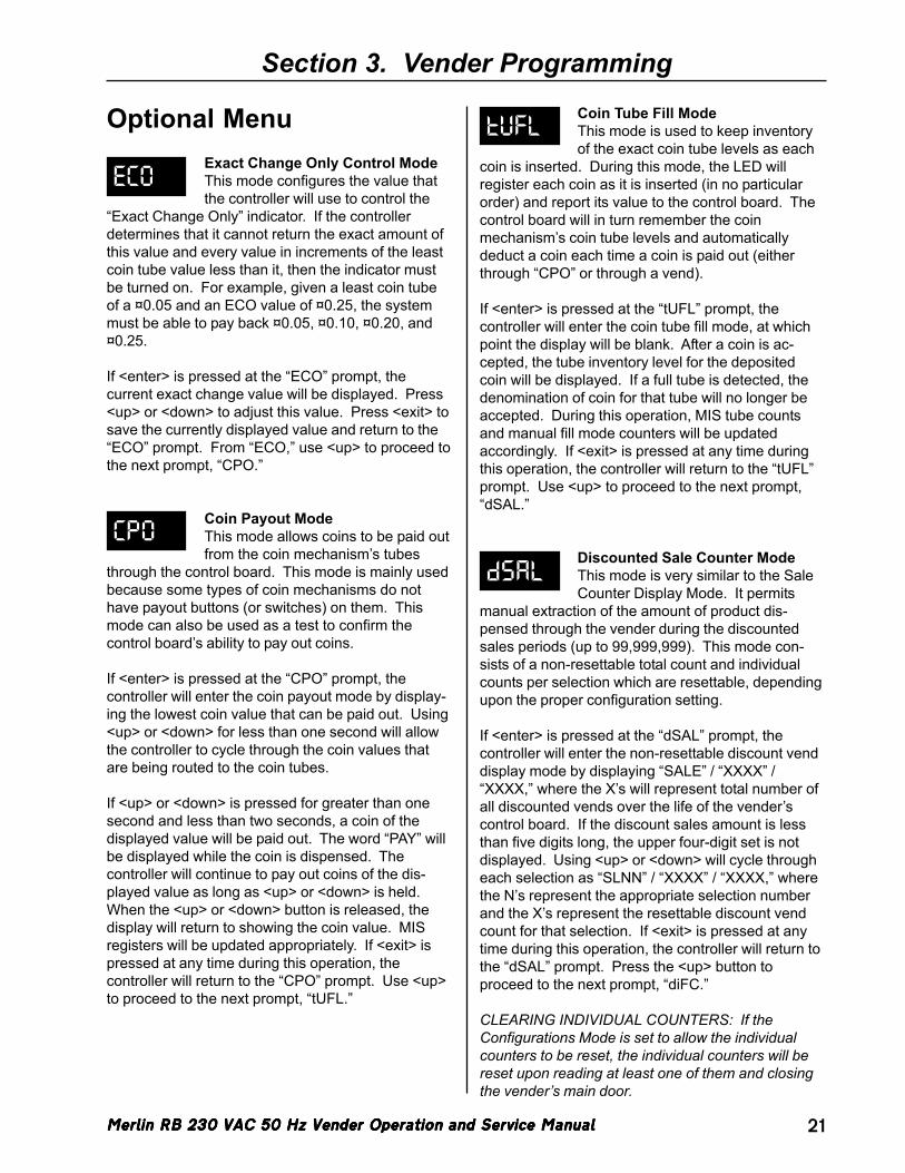
Merlin RB 230 VAC 50 Hz Vender Operation and Service ManualMerlin RB 230 VAC 50 Hz Vender Operation and Service ManualMerlin RB 230 VAC 50 Hz Vender Operation and Service ManualMerlin RB 230 VAC 50 Hz Vender Operation and Service ManualMerlin RB 230 VAC 50 Hz Vender Operation and Service Manual 21
Section 3. Vender Programming
Optional MenuExact Change Only Control ModeThis mode configures the value thatthe controller will use to control the
“Exact Change Only” indicator. If the controllerdetermines that it cannot return the exact amount ofthis value and every value in increments of the leastcoin tube value less than it, then the indicator mustbe turned on. For example, given a least coin tubeof a ¤0.05 and an ECO value of ¤0.25, the systemmust be able to pay back ¤0.05, ¤0.10, ¤0.20, and¤0.25.
If <enter> is pressed at the “ECO” prompt, thecurrent exact change value will be displayed. Press<up> or <down> to adjust this value. Press <exit> tosave the currently displayed value and return to the“ECO” prompt. From “ECO,” use <up> to proceed tothe next prompt, “CPO.”
Coin Payout ModeThis mode allows coins to be paid outfrom the coin mechanism’s tubes
through the control board. This mode is mainly usedbecause some types of coin mechanisms do nothave payout buttons (or switches) on them. Thismode can also be used as a test to confirm thecontrol board’s ability to pay out coins.
If <enter> is pressed at the “CPO” prompt, thecontroller will enter the coin payout mode by display-ing the lowest coin value that can be paid out. Using<up> or <down> for less than one second will allowthe controller to cycle through the coin values thatare being routed to the coin tubes.
If <up> or <down> is pressed for greater than onesecond and less than two seconds, a coin of thedisplayed value will be paid out. The word “PAY” willbe displayed while the coin is dispensed. Thecontroller will continue to pay out coins of the dis-played value as long as <up> or <down> is held.When the <up> or <down> button is released, thedisplay will return to showing the coin value. MISregisters will be updated appropriately. If <exit> ispressed at any time during this operation, thecontroller will return to the “CPO” prompt. Use <up>to proceed to the next prompt, “tUFL.”
ECO
CPO
Coin Tube Fill ModeThis mode is used to keep inventoryof the exact coin tube levels as each
coin is inserted. During this mode, the LED willregister each coin as it is inserted (in no particularorder) and report its value to the control board. Thecontrol board will in turn remember the coinmechanism’s coin tube levels and automaticallydeduct a coin each time a coin is paid out (eitherthrough “CPO” or through a vend).
If <enter> is pressed at the “tUFL” prompt, thecontroller will enter the coin tube fill mode, at whichpoint the display will be blank. After a coin is ac-cepted, the tube inventory level for the depositedcoin will be displayed. If a full tube is detected, thedenomination of coin for that tube will no longer beaccepted. During this operation, MIS tube countsand manual fill mode counters will be updatedaccordingly. If <exit> is pressed at any time duringthis operation, the controller will return to the “tUFL”prompt. Use <up> to proceed to the next prompt,“dSAL.”
Discounted Sale Counter ModeThis mode is very similar to the SaleCounter Display Mode. It permits
manual extraction of the amount of product dis-pensed through the vender during the discountedsales periods (up to 99,999,999). This mode con-sists of a non-resettable total count and individualcounts per selection which are resettable, dependingupon the proper configuration setting.
If <enter> is pressed at the “dSAL” prompt, thecontroller will enter the non-resettable discount venddisplay mode by displaying “SALE” / “XXXX” /“XXXX,” where the X’s will represent total number ofall discounted vends over the life of the vender’scontrol board. If the discount sales amount is lessthan five digits long, the upper four-digit set is notdisplayed. Using <up> or <down> will cycle througheach selection as “SLNN” / “XXXX” / “XXXX,” wherethe N’s represent the appropriate selection numberand the X’s represent the resettable discount vendcount for that selection. If <exit> is pressed at anytime during this operation, the controller will return tothe “dSAL” prompt. Press the <up> button toproceed to the next prompt, “diFC.”
CLEARING INDIVIDUAL COUNTERS: If theConfigurations Mode is set to allow the individualcounters to be reset, the individual counters will bereset upon reading at least one of them and closingthe vender’s main door.
tUFL
dSAL
Merlin RB 230 VAC 50 Hz Vender Operation and Service ManualMerlin RB 230 VAC 50 Hz Vender Operation and Service ManualMerlin RB 230 VAC 50 Hz Vender Operation and Service ManualMerlin RB 230 VAC 50 Hz Vender Operation and Service ManualMerlin RB 230 VAC 50 Hz Vender Operation and Service Manual22
Section 3. Vender Programming
Differential Cash Counter ModeThis mode is comparable to the CashCounter Display Mode. It permits
monitoring of the difference between discountedprices and regular prices. This mode consists only ofa non-resettable total count.
If <enter> is pressed at the “diFC” prompt, thecontroller will enter the non-resettable cash displaymode by displaying “CASH” / “YXXX” / “XX.XX,”where the X’s will represent total discounted value ofall discounted vends over the life of the vender’scontrol board. If product is sold for less than thenormal vend price, “Y” will be a negative sign (“-”); ifproduct is sold for greater than the normal vendprice, “Y” will be a blank. A decimal point will bedisplayed in the appropriate position with the lowerfour digits. If the discount amount is less than fivedigits long, the upper four-digit set is not displayed. If<exit> is pressed at any time during this operation,the controller will return to the “diFC” prompt. Pressthe <up> button to proceed to the next prompt,“SdiS.”
Discount Price Setting ModeThis mode is used to set discountprices for each selection. This mode
works in conjunction with the built-in timer in the“tinE” mode. Before entering into the “tinE” mode, allselections to be discounted should be set to “1” inthe “StCL” mode. Then, the time the discountedselections are to be activated should be set by using“dSCn,” located under “dAY” in the “tinE” mode.
If <enter> is pressed at the “SdiS” prompt, thecontroller will enter the discount price setting mode.The display will alternately flash “ALL” and the lastdiscount price set for all selections. If <up> ispressed, the controller will alternately display “P1”and the discount price of selection 1. Using <up> or<down> will allow the controller to cycle through eachavailable individual discount price. This is theselection level. If <exit> is pressed at any time atthis level, the controller will return to the “SdiS”prompt. Use <up> to proceed to the next prompt,“StCL.”
If <enter> is pressed at the selection level, thedisplay will continuously show the current discountprice for the displayed selection. Using <up> or<down> will increase or decrease the discount price.When the desired discount price is on the display,press <exit> to save that price and return to theselection level. If the “ALL” discount price is set, allindividual discount prices will be set to this value.
diFC
SdiS
Set Timer Control ModeThis mode is used to choose whichselections to turn off by either using
the built-in timer or with the optional key switch kit.This mode must be set to enable one or all of theselections in order for the timer or key switch tooperate. The timer or key switch will control anyselections set to “1.” Selections set to “0” willfunction normally.
If <enter> is pressed at the “StCL” prompt, thedisplay will show “ALLX” or “tY X,” depending onwhether the “ALL” setting is being used or an indi-vidual selection is being accessed. “Y” representsthe individual selection number, and “X” representsthe status of “ALL” or the individual selection (“1” ifenabled or “0” if disabled). The “X” character will beflashing. Using <up> or <down> will toggle “X”between “0” and “1.” When the desired setting is onthe display, pressing <exit> will save that setting andreturn the controller to the selection level. If “ALLX”is being used, all selections will be set to this value.If <exit> is pressed at the selection level, the control-ler will return to the “StCL” prompt. Use <up> toproceed to the next prompt, “tinE.”
Time Setting ModeIf <enter> is pressed at the “tinE”prompt, the controller will enter the
time setting mode by displaying “YEAr.” Using <up>or <down> will cycle through all available time settingoptions. If <exit> is pressed at any time during thislevel of the operation, the controller will return to the“tinE” prompt. From the “tinE” prompt, use <up> toproceed to the next prompt, “FriG.”
The following options can be selected in “tinE”:
• “YEAr” - current year• “dAtE” - current date (month, day)• “hour” - current time (hours, minutes)• “SEtd” - current day of week• “StOP” - turn real time clock on / off*• “dAY” - timer settings• “dSt” - display current time• “dLt” - daylight savings time enable / disable
* - NOTE: The “StOP” feature is used to conservethe control board’s built-in lithium battery when theboard is placed in storage for long periods of time.The shelf life of the battery is about three years withthe clock turned on or about ten years with the clockturned off.
StCL
tinE
Merlin RB 230 VAC 50 Hz Vender Operation and Service ManualMerlin RB 230 VAC 50 Hz Vender Operation and Service ManualMerlin RB 230 VAC 50 Hz Vender Operation and Service ManualMerlin RB 230 VAC 50 Hz Vender Operation and Service ManualMerlin RB 230 VAC 50 Hz Vender Operation and Service Manual 23
Section 3. Vender Programming
• YEArIf <enter> is pressed at the “YEAr” prompt, thecurrent year is displayed and will be flashing.Pressing <up> or <down> at this point will in-crease or decrease the year setting. Pressing<exit> at this point will save the displayed yearsetting and return the controller to the timeselection level.
• datEIf <enter> is pressed at the “dAtE” prompt, thecurrent date is displayed. The left two digits of thedisplay show the current month, and the right twodigits show the current day. The month settingwill be flashing. Pressing <up> or <down> at thispoint will increase or decrease the month setting.If <enter> is pressed, the day setting will flash.<Up> or <down> can now be used to set the day.Pressing <enter> again will cause the monthsetting to flash again. Pressing <exit> in thismode will save the displayed month and daysettings and return the controller to the timeselection level.
• hourIf <enter> is pressed at the “hour” prompt, thecurrent time is displayed in a 24-hour format. Theleft two digits of the display show the current hour,and the right two digits show the current minutes.The hour setting will be flashing. Pressing <up>or <down> at this point will increase or decreasethe hour setting. If <enter> is pressed, the minutesetting will flash. <Up> or <down> can now beused to set the minutes. Pressing <enter> at thispoint will cause the hour setting to flash again.Pressing <exit> in this mode will save the dis-played hour and minutes setting and return thecontroller to the time selection level.
• SEtdIf <enter> is pressed at the “SEtd” prompt, thecurrent day of the week is shown. Pressing <up>or <down> will cycle through all days. When thedesired day is selected, press <exit> to save thedisplayed day setting and return the controller tothe time selection level.
• StOPIf <enter> is pressed at the “StOP” prompt, thedisplay will alternately show “CLOC” / ”StOP”. If<enter> is pressed at this point the system clockwill be shut off, the display will show “OFF” forapproximately 1/2 second, and then the displaywill return to the “StOP” prompt. If <exit> ispressed at the “CLOC” / ”StOP” prompt, thecontroller will return to the “StOP” prompt withoutturning off the system clock. To restart thesystem clock, use the “hour” feature to reset thecurrent time. When the current time is reset, thebattery will be turned on automatically.
• dAYIf <enter> is pressed at the “dAY” prompt, thecontroller will enter the time range programmingfunction to allow the timer on / off times to be setfor each day of the week. The display will show“ALL.” From this point, there are two differentoptions: “ALL,” to allow the timer to function atthe same time settings every day of the week; andindividual day settings for using different timeblocks for different days. Pressing <up> or<down> will cycle through “ALL” and each day ofthe week. If <enter> is pressed, either at “ALL” oran individual day, the controller will enter into thatparticular day. The display will show “SC-1” /“On,” then the currently set off-time, as listedbelow. If <up> or <down> is pressed at this level,the display will cycle to all other available timersetting modes:
SETTING MODE PROGRAM MEANING“SC-1” / “On” 1st off-time for selections“SC-1” / “OFF” 1st on-time for selections“SC-2” / “On” 2nd off-time for selections“SC-2” / “OFF” 2nd on-time for selections“SC-3” / “On” 3rd off-time for selections“SC-3” / “OFF” 3rd on-time for selections“dScn” / “On” off-time for discounting“dScn” / “OFF” on-time for discounting“FriG” / “On” off-time for refrigeration“FriG” / “OFF” on-time for refrigeration“Lt-1” / “On” 1st off-time for illumination“Lt-1” / “OFF” 1st on-time for illumination“Lt-2” / “On” 2nd off-time for illumination“Lt-2” / “OFF” 2nd on-time for illumination“Lt-3” / “On” 3rd off-time for illumination“Lt-3” / “OFF” 3rd on-time for illumination
Merlin RB 230 VAC 50 Hz Vender Operation and Service ManualMerlin RB 230 VAC 50 Hz Vender Operation and Service ManualMerlin RB 230 VAC 50 Hz Vender Operation and Service ManualMerlin RB 230 VAC 50 Hz Vender Operation and Service ManualMerlin RB 230 VAC 50 Hz Vender Operation and Service Manual24
Section 3. Vender Programming
To set “On” and “OFF” times for the timer, press<enter> upon reaching the desired timer settingmode. The controller will enter into that particulartimer setting mode. The display will show thecurrent setting, with the hour flashing. Thisindicates that the hour can now be changed.Pressing <up> or <down> will change the hour ofthis particular setting. Pressing <enter> will lockin the hour setting, and the minutes will begin toflash (which indicates that the minutes can nowbe changed). Pressing <up> or <down> willchange the minutes of this setting. Pressing<exit> at any time during this operation will lock inthe changes and bring the controller back to thetimer setting mode, followed by the time set forthat particular mode. (Example: “SC-1” / “On” /“0900.”)
At this point, <up> or <down> will cycle through alltimer setting modes listed previously. From thislevel, pressing <exit> will return the display to theday of the week. Pressing <exit> again will returnthe display to “dAY.” Press <up> to proceed to“StOP.”
Note: If certain selections are being set to go offand come back on at a programmed time, firstenter into “SC-1” / “On” to set the first off-time forselections. Then, program the first return on-timefor selections by entering into “SC-1” / “OFF.” Forthe timer to be able to control the selections,those selections must be set to “1” in the “StCL”mode.
• dStIf <enter> is pressed at the “dSt” prompt, thedisplay will show “dStX,” where the ‘X’ will beflashing. If X = 0, this indicates that the currenttime is not being displayed in place of the POSmessage in sales mode. If X = 1, the time isbeing displayed in sales mode. Using <up> or<down> will toggle the value of “X.” If <exit> ispressed at this point, the currently displayed valueof “X” will be saved and the controller will return tothe “dSt” prompt.
• dLtIf <enter> is pressed at the “dLt” prompt, thedisplay will show “dLtX,” where the “X” will beflashing. If X = 0, this indicates that the controllerwill not adjust the time for daylight savings. If X =1, the controller will adjust the time for daylightsavings. Using <up> or <down> will toggle thevalue of “X.” If <exit> is pressed at this point thecurrently displayed value of “X” will be saved andthe controller will return to the “dLt” prompt.When enabled, the controller will advance thesystem time forward one hour at 2:00 AM on thefirst Sunday of April. It will back up the systemtime one hour at 2:00 AM of the last Sunday ofOctober. (Note: This conforms to North Ameri-can Daylight Savings Time standards. Otherstandards are not available at this time.)
Refrigeration Control ModeIf <enter> is pressed at the “FriG”prompt, the controller will enter the
refrigeration control mode. Using <up> or <down>will cycle through the various refrigeration controlsettings (“Enb,” “Strt,” “StoP,” “dEG,” “SEtP,” “Stor,”“dSP,” and “rELY”). If <exit> is pressed, the control-ler will return to the “FriG” prompt. Press <up> toproceed to the next prompt, “PAS.”
• EnbIf <enter> is pressed at “Enb,” the controller willdisplay “EnbX.” “X” will be flashing, indicating thatit can be edited. If X = 1, the energy conservationcontrol will be enabled. This means the cabinettemperature will be allowed to rise to the pro-grammed storage level during programmed timeblocks. If X = 0, the energy conservation modewill be disabled, and the machine will function asnormal. Pressing <up> or <down> will toggle “X”between “1” (enabled) and “0” (disabled). Press-ing <exit> will save the displayed setting andreturn the controller to the “Enb” prompt.
FriG
Merlin RB 230 VAC 50 Hz Vender Operation and Service ManualMerlin RB 230 VAC 50 Hz Vender Operation and Service ManualMerlin RB 230 VAC 50 Hz Vender Operation and Service ManualMerlin RB 230 VAC 50 Hz Vender Operation and Service ManualMerlin RB 230 VAC 50 Hz Vender Operation and Service Manual 25
Section 3. Vender Programming
• StrtIf <enter> is pressed at the “Strt” prompt, thecontroller will enter the start energy conservationtime setting routine. Upon entry into this routine,the display will show “dAY.” Pressing <exit> atthis point will return to the “Strt” prompt withoutsaving any changes.
If <enter> is pressed at the “dAY” prompt, thecontroller will enter the day of the week settingroutine. Upon entry into this routine, the displaywill show “ALL,” representing every day of theweek. Pressing <up> or <down> will rotatethrough “Sun,” “Mon,“ “tuE,” “Wed,” “thu,” “Fri,”“Sat,” or “ALL.” Pressing <enter> at any of theseprompts will cause the controller to enter thehour:minute time setting routine for that day. Thedisplay will show the current four-digit hour andminute setting, in 24-hour format. The hoursetting will be flashing to indicate that it can bemodified. Pressing <up> or <down> will increaseor decrease the hour. Pressing <enter> will stopthe hour from flashing and cause the minutes toflash, indicating that they can be modified. At thispoint, pressing <up> or <down> will increase ordecrease the minutes value. Pressing <exit> willsave the hour and minute setting for the corre-sponding day value and will return to the promptfor that day. Pressing <exit> again will return thecontroller to the “dAY” prompt. Pressing <exit>one more time will return the controller to the“Strt” prompt.
• StoPIf <enter> is pressed at the “StoP” prompt, thecontroller will enter the stop energy conservationtime setting routine. Upon entry into this routine,the display will show “dAY.” Pressing <exit> atthis point will return the controller to the “StoP”prompt without saving any changes.
If <enter> is pressed at the “dAY” prompt, thecontroller will enter the day of the week settingroutine. Upon entry into this routine, the displaywill show “ALL,” representing every day of theweek. Pressing <up> or <down> will rotatethrough “Sun,” “Mon,“ “tuE,” “Wed,” “thu,” “Fri,”“Sat,” or “ALL.” Pressing <enter> at any of theseprompts will cause the controller to enter thehour:minute time setting routine for that day. Thedisplay will show the current four-digit hour andminute setting in 24-hour format. The hour settingwill be flashing to indicate that it can be modified.Pressing <up> or <down> will increase or de-crease the hour. Pressing <enter> will stop thehour from flashing and cause the minutes to flash,indicating that they can be modified. At this point,pressing <up> or <down> will increase or de-crease the minutes value. Pressing <exit> willsave the hour and minute setting for the corre-sponding day value and will return the controller tothe prompt for that day. Pressing <exit> again willreturn the controller to the “dAY” prompt. Press-ing <exit> one more time will return the controllerto the “StoP” prompt.
• dEGIf <enter> is pressed at the “dEG” prompt, thecontroller will display “dEGX,” where “X” will beflashing “C” if the controller is currently in Celsiusmode, or “F” if the controller is currently in Fahr-enheit mode. Pressing <up> or <down> willtoggle “X” between “C” and “F.” Pressing <exit>at this point will save the displayed temperaturemode and return the controller to the “dEG”prompt.
• SEtPIf <enter> is pressed at the “SetP” prompt, thecontroller will display the current set point tem-perature setting, “xx C” or xx F,” depending on thedegree (“dEG”) mode setting. The cold set pointdefault is 2°C. Pressing <up> or <down> willadjust the temperature value by 0.5°C. The setpoint temperature can be adjusted from -4°Cthrough 7°C. Pressing <exit> at this point willsave the displayed temperature and return thecontroller to “SetP.”

Merlin RB 230 VAC 50 Hz Vender Operation and Service ManualMerlin RB 230 VAC 50 Hz Vender Operation and Service ManualMerlin RB 230 VAC 50 Hz Vender Operation and Service ManualMerlin RB 230 VAC 50 Hz Vender Operation and Service ManualMerlin RB 230 VAC 50 Hz Vender Operation and Service Manual26
Section 3. Vender Programming
• StorIf <enter> is pressed at the “Stor” prompt, thecontroller will display the current storage (forenergy conservation mode) temperature setting,“xx C” or “xx F,” depending on the degree (“dEG”)mode setting. The default storage temperature is14°C. Pressing <up> or <down> will adjust thetemperature value by 0.5°C. The storage tem-perature can be adjusted from 7°C through 24°C.Pressing <exit> at this point will save the dis-played temperature and return the controller to“Stor.”
• dSPIf <enter> is pressed at the “dSP” prompt, thecontroller will display “dSPX,” where “X” will be “0”if the controller is not currently displaying thecabinet temperature, or “1” if the controller iscurrently displaying the cabinet temperature inaddition to the POS message. Pressing <up> or<down> will toggle “X” between “0” and “1.”Pressing <exit> at this point will save the currentlydisplayed setting and return the controller to the“dSP” prompt.
• rELYIf <enter> is pressed at the “rELY” prompt, thecontroller will enter the relay test mode by display-ing “Fan.” If <exit> is pressed in this mode, theuser will return to the “rELY” prompt. Using <up>or <down> will toggle between the followingsubmodes:
• “Fan “ - evaporator fan relay• “LitE” - machine light control relay• “Htr “ - heater kit relay• “CnPr” - compressor relay
If <enter> is pressed at any of these prompts, thecontroller will alternately flash the prompt and theword “OFF,“ if that relay is currently off; or theword “On,“ if that relay is currently on. Pressing<up> or <down> will toggle the alternate displayword between “OFF” and “ON.” Pressing <enter>at this point will override that relay’s current statusuntil either the status is changed or until the“rELY” mode is exited completely. The display willreturn to the relay test mode. When the “rELY”mode is exited, all relays will return to the statethey were in prior to entering the “rELY” mode.
NOTE: In this feature, the user has the ability tocontinuously turn the compressor on and off. Beaware that quickly restarting the compressor mayresult in serious damage to the compressor.
Password Preview ModeOn the Merlin RB vender, the totalhistorical and individual sales counts
can be accessed externally, as well as the errormode, by entering the external password. Neitherthe sales counts nor the errors can be clearedexternally. The Password Preview Mode allows theexternal password to be changed.
If <enter> is pressed at the “PAS” prompt, thecontroller will display the external password previewmode. The first digit of the number will be flashing.Pressing <up> or <down> will adjust the currentlyflashing digit up or down. Pressing <enter> will savethe currently flashing digit and cause the next digit ofthe password to begin flashing. All digits may bemodified in this manner. Pressing <exit> at any pointin the procedure will save the currently displayedpassword and return the controller to the “PAS”prompt. Use <up> to proceed to the next prompt,“LAnG.”
Note: Password digits correspond to the selectionswitches. If a digit is set to “0” (zero), it will not bepossible to enter the external password.
PAS
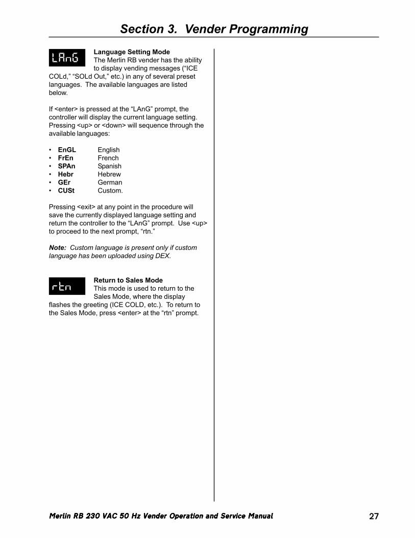
Merlin RB 230 VAC 50 Hz Vender Operation and Service ManualMerlin RB 230 VAC 50 Hz Vender Operation and Service ManualMerlin RB 230 VAC 50 Hz Vender Operation and Service ManualMerlin RB 230 VAC 50 Hz Vender Operation and Service ManualMerlin RB 230 VAC 50 Hz Vender Operation and Service Manual 27
Section 3. Vender Programming
LAnGLanguage Setting ModeThe Merlin RB vender has the abilityto display vending messages (“ICE
COLd,” “SOLd Out,” etc.) in any of several presetlanguages. The available languages are listedbelow.
If <enter> is pressed at the “LAnG” prompt, thecontroller will display the current language setting.Pressing <up> or <down> will sequence through theavailable languages:
• EnGL English• FrEn French• SPAn Spanish• Hebr Hebrew• GEr German• CUSt Custom.
Pressing <exit> at any point in the procedure willsave the currently displayed language setting andreturn the controller to the “LAnG” prompt. Use <up>to proceed to the next prompt, “rtn.”
Note: Custom language is present only if customlanguage has been uploaded using DEX.
Return to Sales ModeThis mode is used to return to theSales Mode, where the display
flashes the greeting (ICE COLD, etc.). To return tothe Sales Mode, press <enter> at the “rtn” prompt.
rtn
Merlin RB 230 VAC 50 Hz Vender Operation and Service ManualMerlin RB 230 VAC 50 Hz Vender Operation and Service ManualMerlin RB 230 VAC 50 Hz Vender Operation and Service ManualMerlin RB 230 VAC 50 Hz Vender Operation and Service ManualMerlin RB 230 VAC 50 Hz Vender Operation and Service Manual28
Section 4. Vend Cycle
Vend CycleStand-By ConditionIn a stand-by condition, the vender will show thegreeting and possibly the vend price (if set for asingle price or if all prices are set to same) and achoice of other optional features on the LED display.If a select button is pressed prior to reaching thevend price (establishing a credit), the display willshow the vend price for that selection. This willindicate to the customer more money is needed forthat particular selection.
Establishing CreditAs coins are inserted into the coin mechanism, acorresponding credit count will appear on the display.The coin mechanism will continue to accept coinsuntil the highest vend price has been achieved. Allcoins in excess of the vend price will be returned tothe coin cup. Once the vend price has beenachieved, the control board will set up a creditenabling a vend to be made for any selection equalto or less than the established credit.
Valid SelectionThe vender’s control board constantly sends a logiclevel signal to the common position of each selectswitch. When a selection is made, the selectionswitch closes. This allows the low voltage signal totravel from the switch’s common position through theswitch and out the normally open position of thatswitch to the select switch’s harness connection onthe control board.
Vend SequenceAt this time (if there has not been a previous soldout), the control board distributes 24 volts DCthrough the door and cabinet wiring harnesses anddirectly to the coil of the chosen vend motor. Simul-taneously the display will scroll. This is an indicationto the customer a vend is in progress and to pleasewait. As the vend motor receives power, it will turnthe rotor in an attempt to vend a can.
Product DeliveryAs the product drops, the vibration from the impactallows the delivery sensor to send a low voltagesignal to the vender’s control board, indicating that aproduct has been vended. After the control boardreceives the sensor’s signal, it will take into accounthow the vender is programmed (set depth) and willact accordingly. If the first can has just vended, thecontrol board will kill all power to the vend motor atthe exact same time that a product drop is registered(this avoids a multiple vend of the next product to therear of the cabinet). As the next can vends, thecontrol board will cycle the vend motor to pick up
another load of product. This allows a quick vend,less than three (3) seconds, for the next customer.
Note: The control board will go through a learningprocess known as the Learning Mode. It will be reseteither on power down/up or a door opening/closing.This allows the vender’s controller to decide which isthe front or rear product. The Learning Mode acts inconjunction with the depth setting to allow for anautomatic reload after the rear can has vended. Howit works: The controller will notice the first “long-timed out” vend cycle during the learning process.From this, the controller will know the very next vendwill be the front product.
Column SequencingIf a selection has multiple columns assigned to it, thesame column is vended each time the selectionbutton is pressed until the number of times vended isequal to the depth of the column. Then, that selec-tion proceeds to the next column assigned. This isto allow the columns to vend evenly.
Sold-OutUpon selection, the display will cycle to show thevend progress. After ten (10) to twelve (12) seconds(if a drop of product is not detected), the display willshow “SOLd OUt.” A sold out may be due to:
1. The column attempted is jammed, thereforeproduct does not drop;
2. The column attempted is genuinely sold out;3. The sensor is out of adjustment and does not
detect the product drop; or4. If any (or all selections) doesn’t have a column
assigned, it will read “SOLd OUt.”
The digital display will indicate “SOLd OUt.” Thissignals to the customer to make another selection orpush the coin return lever for a full refund. If set forforced attempt, the customer must make an initialselection. If the initial selection is sold out, thecustomer will be allowed a full refund or an alternateselection. If the vender is totally sold out of a prod-uct, the “sold out” message on the digital display willbe continuous. No money will be accepted into thevender in a total sold out condition.
Resetting Sold Out SelectionsA sold-out condition is only cleared by the vender’sdoor switch, by opening the vender’s main door. If asold out condition is not cleared, the controller willnot attempt to vend from that selection. The displaywill not indicate a vend is in progress. It will auto-matically show “SOLd OUt” upon pressing the selectbutton (after reaching a vend price).
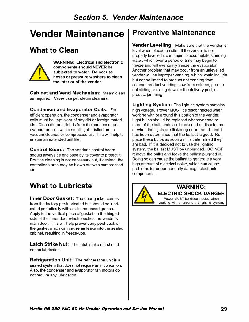
Merlin RB 230 VAC 50 Hz Vender Operation and Service ManualMerlin RB 230 VAC 50 Hz Vender Operation and Service ManualMerlin RB 230 VAC 50 Hz Vender Operation and Service ManualMerlin RB 230 VAC 50 Hz Vender Operation and Service ManualMerlin RB 230 VAC 50 Hz Vender Operation and Service Manual 29
Section 5. Vender Maintenance
Vender MaintenanceWhat to Clean
WARNING: Electrical and electroniccomponents should NEVER besubjected to water. Do not usehoses or pressure washers to cleanthe interior of the vender.
Cabinet and Vend Mechanism: Steam cleanas required. Never use petroleum cleaners.
Condenser and Evaporator Coils: Forefficient operation, the condenser and evaporatorcoils must be kept clear of any dirt or foreign materi-als. Clean dirt and debris from the condenser andevaporator coils with a small light-bristled brush,vacuum cleaner, or compressed air. This will help toensure an extended unit life.
Control Board: The vender’s control boardshould always be enclosed by its cover to protect it.Routine cleaning is not necessary but, if desired, thecontroller’s area may be blown out with compressedair.
What to LubricateInner Door Gasket: The door gasket comesfrom the factory pre-lubricated but should be lubri-cated periodically with a silicone-based grease.Apply to the vertical piece of gasket on the hingedside of the inner door which touches the vender’smain door. This will help prevent any peel-back ofthe gasket which can cause air leaks into the sealedcabinet, resulting in freeze-ups.
Latch Strike Nut: The latch strike nut shouldnot be lubricated.
Refrigeration Unit: The refrigeration unit is asealed system that does not require any lubrication.Also, the condenser and evaporator fan motors donot require any lubrication.
Preventive MaintenanceVender Levelling: Make sure that the vender islevel when placed on site. If the vender is notproperly levelled it can begin to accumulate standingwater, which over a period of time may begin tofreeze and will eventually freeze the evaporator.Another problem that may occur from an unlevelledvender will be improper vending, which would includebut not be limited to product not vending fromcolumn, product vending slow from column, productnot sliding or rolling down to the delivery port, orproduct jamming.
Lighting System: The lighting system containshigh voltage. Power MUST be disconnected whenworking with or around this portion of the vender.Light bulbs should be replaced whenever one ormore of the bulb ends are blackened or discoloured,or when the lights are flickering or are not lit, and ithas been determined that the ballast is good. Re-place these bulbs as soon as it is determined theyare bad. If it is decided not to use the lightingsystem, the ballast MUST be unplugged. DO NOTremove the bulbs and leave the ballast plugged in.Doing so can cause the ballast to generate a veryhigh amount of electrical noise, which can causeproblems for or permanently damage electroniccomponents.
!
WARNING:ELECTRIC SHOCK DANGER
Power MUST be disconnected whenworking with or around the lighting system.

Merlin RB 230 VAC 50 Hz Vender Operation and Service ManualMerlin RB 230 VAC 50 Hz Vender Operation and Service ManualMerlin RB 230 VAC 50 Hz Vender Operation and Service ManualMerlin RB 230 VAC 50 Hz Vender Operation and Service ManualMerlin RB 230 VAC 50 Hz Vender Operation and Service Manual30
Section 6. Vender Troubleshooting
Main Detailed Error Corrective Actiondoor (door switch - no detailed error)
Check and / or replace the door switch or door switch harnessing.
SELS SS01 thru SS03 (selection switch closed) Fix stuck button / switch or replace switch.CC (changer communication) Check changer harness connections.tS (changer tube sensor) Consult changer manufacturer.IC (inlet chute blocked) Check vender’s coin chute for blockage.tJ (changer tube jam) Check changer’s coin tubes / tube sensors.CrCH (changer ROM checksum) Consult changer manufacturer.CSF (invalid changer scale factor) Consult changer manufacturer.EE (excessive escrow) Check for stuck coin return lever.nJ (acceptor coin jam) Check for blockage or dirty sensor in acceptor.LA (low acceptance rate) Consult changer manufacturer.bC (bill validator communications) Check bill validator harness connections.bFUL (bill validator cash box full) Remove bills from cash box.biLL (bill validator motor) Consult bill validator manufacturer.bJ (bill jam) Remove jammed bill or clean bill sensors.brCH (bill acceptor ROM checksum error) Consult bill validator manufacturer.bOPn (bill validator cash box open) Close bill acceptor cash box.bS (bill validator sensor) Remove obstruction or clean sensors.bSF (invalid bill acceptor scale factor) Consult bill validator manufacturer.rC (card reader communications error) Check card reader harness connections.rSF (invalid card reader scale factor) Consult card reader manufacturer.CrXY (other card reader error) Consult card reader manufacturer.
CHUt CS (chute sensor always on) Adjust chute sensor.StS UAxx (unassigned column) Correct space to sales setting, if necessary.
SEnS (temperature sensor) Check for a cut or disconnected temperature sensor.
CoLd (sensing temperature 1.5°C below cut-out) Check for a welded contact in refrigeration relay or shorted wire from board to refrigeration relay.
CnPr (not cooling within 30 minutes of cut-in)Check “FrG” in programming and check all wiring connections from board to refrigeration unit.
ACLo (rectified voltage under 22 VDC for more than 30 seconds)
Check voltage at wall outlet during the peak of the load with all units (if any others are present in circuit) running.
CHAr
FriG
CArd
bUAL
ACCE
Vender TroubleshootingUsing the Vender’s Error Code SystemThe Merlin RB has a built-in error code diagnostic system that will help in troubleshooting and solving prob-lems. This system is best used in conjunction with the following section, Troubleshooting. These errors arenot a replacement for knowledge of the vender or its operation, but they will lead in the general direction of theproblem. Most vender parts are independent of one another, so most problems can be confined to the item inquestion (such as an LED, coin changer, or select switch), the harnessing connecting it to the control board, orthe control board itself. See Section 3: Vender Programming for detailed instructions on how to use andaccess the vender’s error codes.
Note: It is recommended the error codes be cleared after correcting any problem(s) to prevent confusion andunnecessary work in the future.
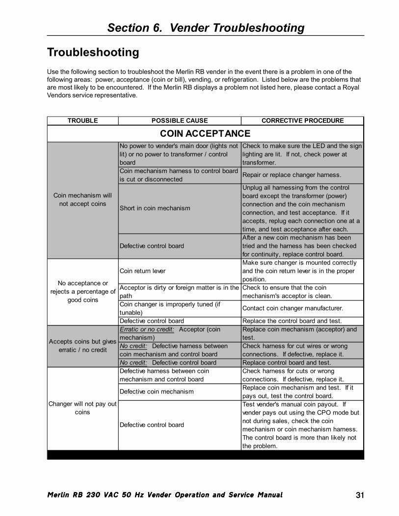
Merlin RB 230 VAC 50 Hz Vender Operation and Service ManualMerlin RB 230 VAC 50 Hz Vender Operation and Service ManualMerlin RB 230 VAC 50 Hz Vender Operation and Service ManualMerlin RB 230 VAC 50 Hz Vender Operation and Service ManualMerlin RB 230 VAC 50 Hz Vender Operation and Service Manual 31
Section 6. Vender Troubleshooting
TroubleshootingUse the following section to troubleshoot the Merlin RB vender in the event there is a problem in one of thefollowing areas: power, acceptance (coin or bill), vending, or refrigeration. Listed below are the problems thatare most likely to be encountered. If the Merlin RB displays a problem not listed here, please contact a RoyalVendors service representative.
TROUBLE POSSIBLE CAUSE CORRECTIVE PROCEDURE
No power to vender's main door (lights not lit) or no power to transformer / control board
Check to make sure the LED and the sign lighting are lit. If not, check power at transformer.
Coin mechanism harness to control board is cut or disconnected
Repair or replace changer harness.
Short in coin mechanism
Unplug all harnessing from the control board except the transformer (power) connection and the coin mechanism connection, and test acceptance. If it accepts, replug each connection one at a time, and test acceptance after each.
Defective control boardAfter a new coin mechanism has been tried and the harness has been checked for continuity, replace control board.
Coin return leverMake sure changer is mounted correctly and the coin return lever is in the proper position.
Acceptor is dirty or foreign matter is in the path
Check to ensure that the coin mechanism's acceptor is clean.
Coin changer is improperly tuned (if tunable)
Contact coin changer manufacturer.
Defective control board Replace the control board and test.Erratic or no credit: Acceptor (coin mechanism)
Replace coin mechanism (acceptor) and test.
No credit: Defective harness between coin mechanism and control board
Check harness for cut wires or wrong connections. If defective, replace it.
No credit: Defective control board Replace control board and test.Defective harness between coin mechanism and control board
Check harness for cuts or wrong connections. If defective, replace it.
Defective coin mechanism Replace coin mechanism and test. If it pays out, test the control board.
Defective control board
Test vender's manual coin payout. If vender pays out using the CPO mode but not during sales, check the coin mechanism or coin mechanism harness. The control board is more than likely not the problem.
Changer will not pay out coins
COIN ACCEPTANCE
Coin mechanism will not accept coins
No acceptance or rejects a percentage of
good coins
Accepts coins but gives erratic / no credit
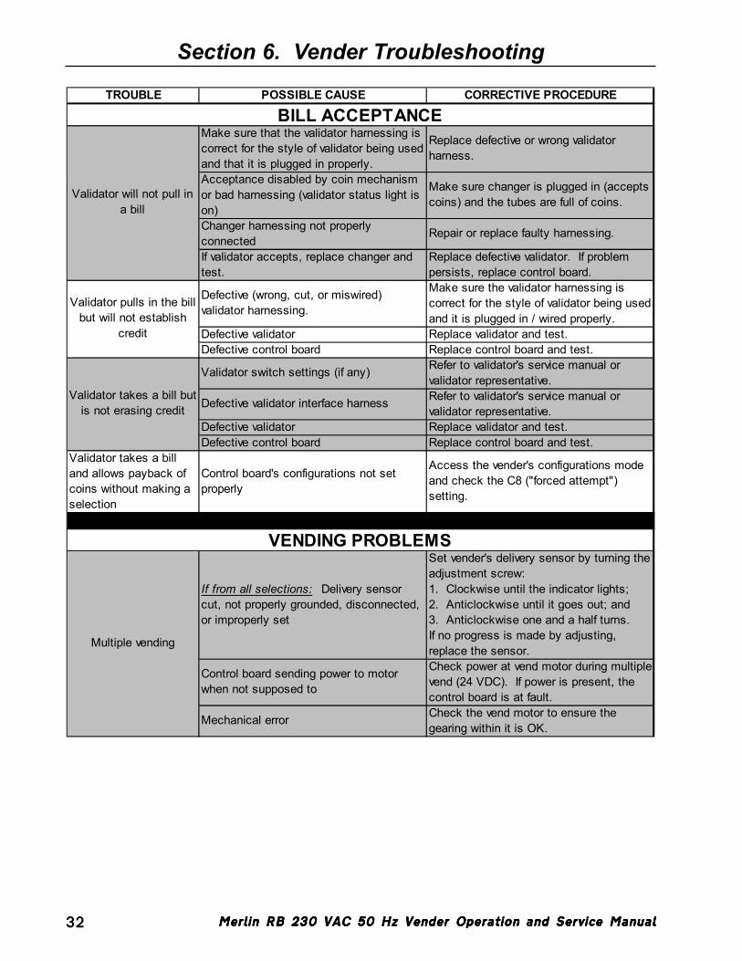
Merlin RB 230 VAC 50 Hz Vender Operation and Service ManualMerlin RB 230 VAC 50 Hz Vender Operation and Service ManualMerlin RB 230 VAC 50 Hz Vender Operation and Service ManualMerlin RB 230 VAC 50 Hz Vender Operation and Service ManualMerlin RB 230 VAC 50 Hz Vender Operation and Service Manual32
Section 6. Vender Troubleshooting
TROUBLE POSSIBLE CAUSE CORRECTIVE PROCEDURE
Make sure that the validator harnessing is correct for the style of validator being used and that it is plugged in properly.
Replace defective or wrong validator harness.
Acceptance disabled by coin mechanism or bad harnessing (validator status light is on)
Make sure changer is plugged in (accepts coins) and the tubes are full of coins.
Changer harnessing not properly connected
Repair or replace faulty harnessing.
If validator accepts, replace changer and test.
Replace defective validator. If problem persists, replace control board.
Defective (wrong, cut, or miswired) validator harnessing.
Make sure the validator harnessing is correct for the style of validator being used and it is plugged in / wired properly.
Defective validator Replace validator and test.Defective control board Replace control board and test.
Validator switch settings (if any) Refer to validator's service manual or validator representative.
Defective validator interface harness Refer to validator's service manual or validator representative.
Defective validator Replace validator and test.Defective control board Replace control board and test.
Validator takes a bill and allows payback of coins without making a selection
Control board's configurations not set properly
Access the vender's configurations mode and check the C8 ("forced attempt") setting.
If from all selections: Delivery sensor cut, not properly grounded, disconnected, or improperly set
Set vender's delivery sensor by turning the adjustment screw:1. Clockwise until the indicator lights;2. Anticlockwise until it goes out; and3. Anticlockwise one and a half turns.If no progress is made by adjusting, replace the sensor.
Control board sending power to motor when not supposed to
Check power at vend motor during multiple vend (24 VDC). If power is present, the control board is at fault.
Mechanical error Check the vend motor to ensure the gearing within it is OK.
VENDING PROBLEMS
Multiple vending
BILL ACCEPTANCE
Validator will not pull in a bill
Validator pulls in the bill but will not establish
credit
Validator takes a bill but is not erasing credit
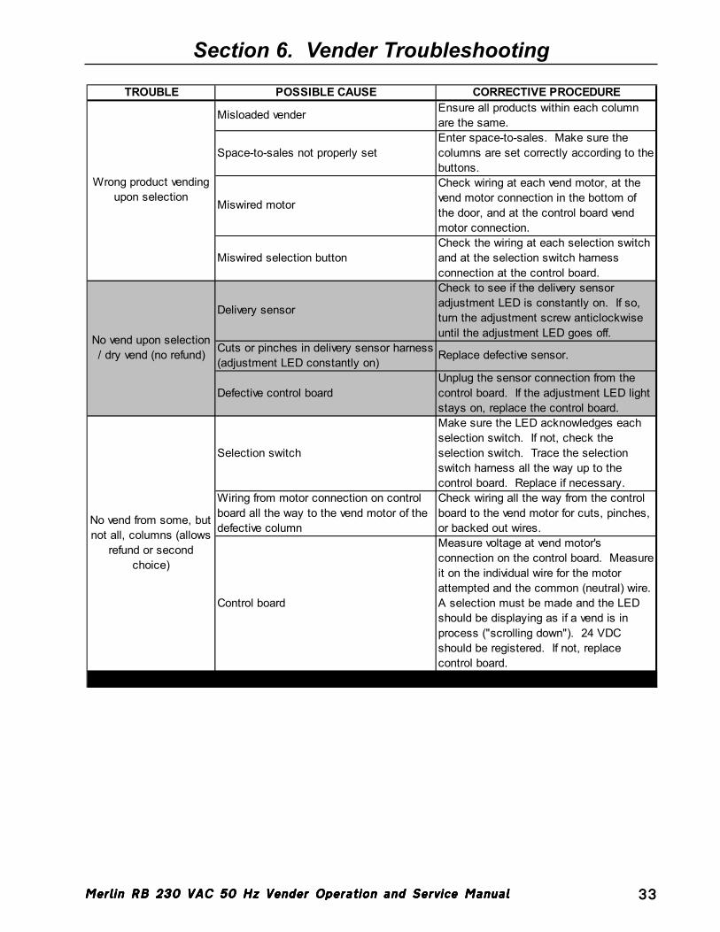
Merlin RB 230 VAC 50 Hz Vender Operation and Service ManualMerlin RB 230 VAC 50 Hz Vender Operation and Service ManualMerlin RB 230 VAC 50 Hz Vender Operation and Service ManualMerlin RB 230 VAC 50 Hz Vender Operation and Service ManualMerlin RB 230 VAC 50 Hz Vender Operation and Service Manual 33
Section 6. Vender Troubleshooting
TROUBLE POSSIBLE CAUSE CORRECTIVE PROCEDURE
Misloaded vender Ensure all products within each column are the same.
Space-to-sales not properly setEnter space-to-sales. Make sure the columns are set correctly according to the buttons.
Miswired motor
Check wiring at each vend motor, at the vend motor connection in the bottom of the door, and at the control board vend motor connection.
Miswired selection buttonCheck the wiring at each selection switch and at the selection switch harness connection at the control board.
Delivery sensor
Check to see if the delivery sensor adjustment LED is constantly on. If so, turn the adjustment screw anticlockwise until the adjustment LED goes off.
Cuts or pinches in delivery sensor harness (adjustment LED constantly on)
Replace defective sensor.
Defective control boardUnplug the sensor connection from the control board. If the adjustment LED light stays on, replace the control board.
Selection switch
Make sure the LED acknowledges each selection switch. If not, check the selection switch. Trace the selection switch harness all the way up to the control board. Replace if necessary.
Wiring from motor connection on control board all the way to the vend motor of the defective column
Check wiring all the way from the control board to the vend motor for cuts, pinches, or backed out wires.
Control board
Measure voltage at vend motor's connection on the control board. Measure it on the individual wire for the motor attempted and the common (neutral) wire. A selection must be made and the LED should be displaying as if a vend is in process ("scrolling down"). 24 VDC should be registered. If not, replace control board.
No vend upon selection / dry vend (no refund)
No vend from some, but not all, columns (allows
refund or second choice)
Wrong product vending upon selection
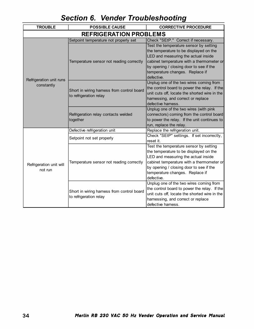
Merlin RB 230 VAC 50 Hz Vender Operation and Service ManualMerlin RB 230 VAC 50 Hz Vender Operation and Service ManualMerlin RB 230 VAC 50 Hz Vender Operation and Service ManualMerlin RB 230 VAC 50 Hz Vender Operation and Service ManualMerlin RB 230 VAC 50 Hz Vender Operation and Service Manual34
Section 6. Vender TroubleshootingTROUBLE POSSIBLE CAUSE CORRECTIVE PROCEDURE
Setpoint temperature not properly set Check "SEtP." Correct if necessary.
Temperature sensor not reading correctly
Test the temperature sensor by setting the temperature to be displayed on the LED and measuring the actual inside cabinet temperature with a thermometer or by opening / closing door to see if the temperature changes. Replace if defective.
Short in wiring harness from control board to refrigeration relay
Unplug one of the two wires coming from the control board to power the relay. If the unit cuts off, locate the shorted wire in the harnessing, and correct or replace defective harness.
Refrigeration relay contacts welded together
Unplug one of the two wires (with pink connectors) coming from the control board to power the relay. If the unit continues to run, replace the relay.
Defective refrigeration unit Replace the refrigeration unit.
Setpoint not set properly Check "SEtP" settings. If set incorrectly, reset it.
Temperature sensor not reading correctly
Test the temperature sensor by setting the temperature to be displayed on the LED and measuring the actual inside cabinet temperature with a thermometer or by opening / closing door to see if the temperature changes. Replace if defective.
Short in wiring harness from control board to refrigeration relay
Unplug one of the two wires coming from the control board to power the relay. If the unit cuts off, locate the shorted wire in the harnessing, and correct or replace defective harness.
REFRIGERATION PROBLEMS
Refrigeration unit runs constantly
Refrigeration unit will not run
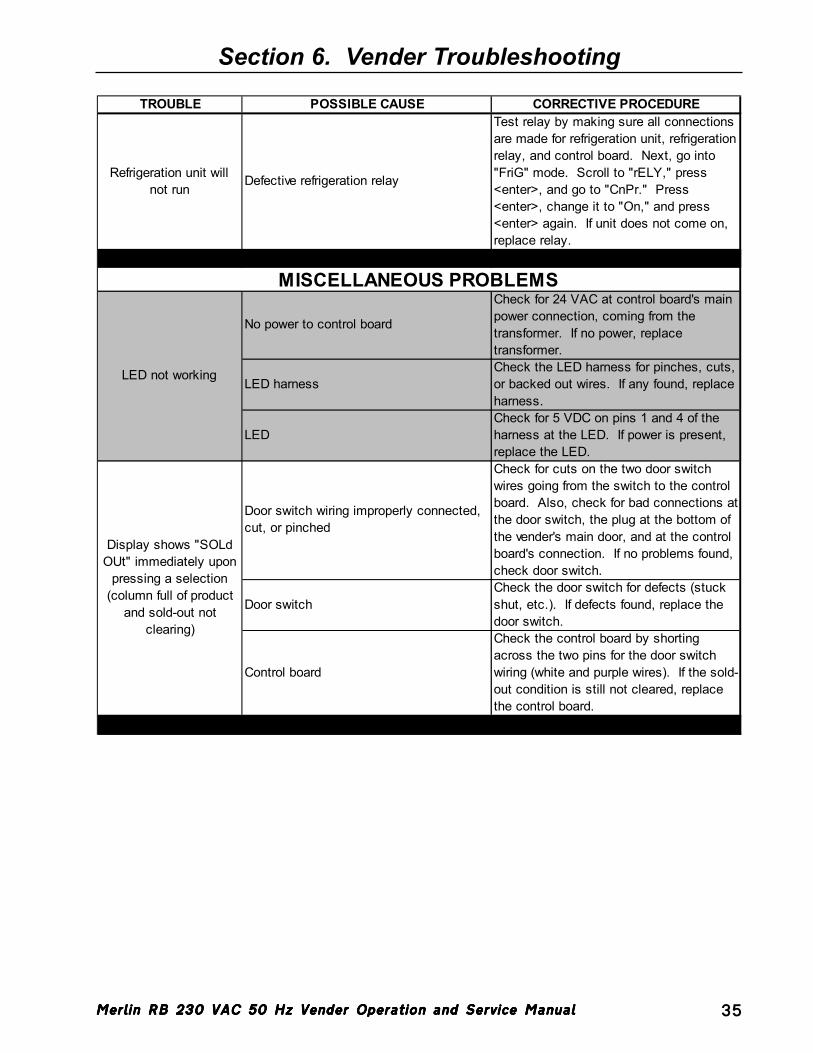
Merlin RB 230 VAC 50 Hz Vender Operation and Service ManualMerlin RB 230 VAC 50 Hz Vender Operation and Service ManualMerlin RB 230 VAC 50 Hz Vender Operation and Service ManualMerlin RB 230 VAC 50 Hz Vender Operation and Service ManualMerlin RB 230 VAC 50 Hz Vender Operation and Service Manual 35
Section 6. Vender Troubleshooting
TROUBLE POSSIBLE CAUSE CORRECTIVE PROCEDURE
Refrigeration unit will not run
Defective refrigeration relay
Test relay by making sure all connections are made for refrigeration unit, refrigeration relay, and control board. Next, go into "FriG" mode. Scroll to "rELY," press <enter>, and go to "CnPr." Press <enter>, change it to "On," and press <enter> again. If unit does not come on, replace relay.
No power to control board
Check for 24 VAC at control board's main power connection, coming from the transformer. If no power, replace transformer.
LED harnessCheck the LED harness for pinches, cuts, or backed out wires. If any found, replace harness.
LEDCheck for 5 VDC on pins 1 and 4 of the harness at the LED. If power is present, replace the LED.
Door switch wiring improperly connected, cut, or pinched
Check for cuts on the two door switch wires going from the switch to the control board. Also, check for bad connections at the door switch, the plug at the bottom of the vender's main door, and at the control board's connection. If no problems found, check door switch.
Door switchCheck the door switch for defects (stuck shut, etc.). If defects found, replace the door switch.
Control board
Check the control board by shorting across the two pins for the door switch wiring (white and purple wires). If the sold-out condition is still not cleared, replace the control board.
MISCELLANEOUS PROBLEMS
LED not working
Display shows "SOLd OUt" immediately upon
pressing a selection (column full of product
and sold-out not clearing)
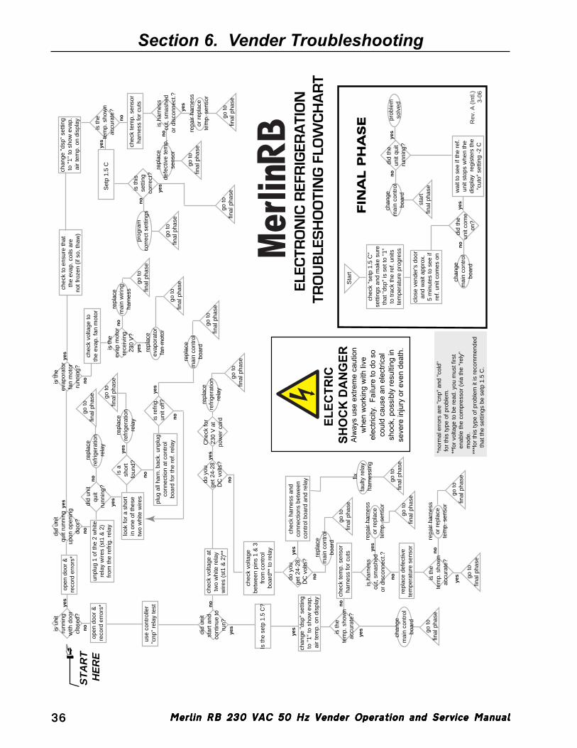
Merlin RB 230 VAC 50 Hz Vender Operation and Service ManualMerlin RB 230 VAC 50 Hz Vender Operation and Service ManualMerlin RB 230 VAC 50 Hz Vender Operation and Service ManualMerlin RB 230 VAC 50 Hz Vender Operation and Service ManualMerlin RB 230 VAC 50 Hz Vender Operation and Service Manual36
Section 6. Vender Troubleshooting
ELEC
TRIC
SH
OC
K D
AN
GER
Alw
ays
use
extre
me
caut
ion
whe
n w
orki
ng w
ith li
veel
ectri
city
. Fa
ilure
to d
o so
coul
d ca
use
an e
lect
rical
shoc
k, p
ossi
bly
resu
lting
inse
vere
inju
ry o
r eve
n de
ath.
yes
yes
yes
no
no
no
no
no
yes
no
yes
yes
no
yes
no
yes
yes
no
yes
no
yes
yes
yes
no n
o
yes
no
no
yes
no
yes
no
yes
clos
e ve
nder
's d
oor
and
wai
t app
rox.
5 m
inut
es to
see
ifre
f. un
it co
mes
on
wai
t to
see
if th
e re
f.un
it st
ops
whe
n th
edi
spla
y r
egis
ters
the
"cut
o" s
ettin
g -2
C
star
tfin
al p
hase
FIN
AL P
HA
SE
no
yes
yes
did
the
unit
com
e on
?
did
the
unit
quit
runn
ing?
chan
ge
mai
n co
ntro
lbo
ard
no
chan
ge
mai
n co
ntro
lbo
ard
prob
lem
solv
ed
chec
k "s
etp
1.5
C"
setti
ngs
and
mak
e su
reth
at "
dsp"
is s
et to
"1"
to tr
ack
the
ref.
units
tem
pera
ture
pro
gres
s
open
doo
r &
reco
rd e
rror
s*
chec
k vo
ltage
toth
e ev
ap. f
an m
otor
chec
k to
ens
ure
that
the
evap
. coi
ls a
reno
t fro
zen
(if s
o, th
aw)
use
cont
rolle
r"c
np"
rela
y te
stpl
ug a
ll ha
rn. b
ack.
unp
lug
conn
ectio
n at
con
trol
boar
d fo
r th
e re
f. re
lay
did
unit
star
t and
co
ntin
ue to
run?
do y
ouge
t 24-
28
DC
vol
ts?
Is th
e se
tp 1
.5 C
?
chec
k vo
ltage
betw
een
pins
1 &
3fr
om c
ontr
olbo
ard*
* to
rel
ay
chec
k ha
rnes
s an
d co
nnec
tions
bet
wee
n co
ntro
l boa
rd a
nd r
elay
do y
ouge
t 24-
28
DC
vol
ts?
chec
k vo
ltage
at
two
whi
te r
elay
wire
s (s
t1 &
2)*
*
repa
ir ha
rnes
sor
rep
lace
tem
p. s
enso
r
repa
ir ha
rnes
sor
rep
lace
tem
p. s
enso
r
chan
ge "
dsp"
set
ting
to "
1" to
sho
w e
vap.
air
tem
p. o
n di
spla
y
is th
e te
mp.
sho
wn
accu
rate
?
repl
ace
mai
n co
ntro
lbo
ard
is th
e te
mp.
sho
wn
accu
rate
?
is h
arne
ss
cut,
smas
hed
or d
isco
nnec
t.?
chec
k te
mp.
sen
sor
harn
ess
for
cuts
repl
ace
defe
ctiv
ete
mpe
ratu
re s
enso
rgo
tofin
al p
hase
go to
final
pha
se
go to
final
pha
se
go to
final
pha
se
go to
final
pha
se
go to
final
pha
se
go to
final
pha
se
fixfa
ulty
rel
ay
harn
essi
ng
is th
eev
apor
ator
fan
mot
orru
nnin
g?
is th
eev
ap m
otor
rece
ivin
g 23
0 V
?
repl
ace
refr
iger
atio
nre
lay
go to
final
pha
se
go to
final
pha
se
go to
final
pha
se
repl
ace
refr
iger
atio
nre
lay
go to
final
pha
se
repl
ace
evap
orat
orfa
n m
otor
go to
final
pha
se
repl
ace
mai
n w
iring
harn
ess
is u
nit
runn
ing
with
doo
rcl
osed
?
open
doo
r &
reco
rd e
rror
s*
did
unit
quit
runn
ing
upon
ope
ning
door
?
did
unit
quit
runn
ing?
is r
efrig
.un
it of
f?
is a
sh
ort
foun
d?
unpl
ug 1
of t
he 2
whi
tere
lay
wire
s (s
t1 &
2)
from
the
refr
ig. r
elay
repl
ace
refr
iger
atio
nre
lay
repl
ace
mai
n co
ntro
lbo
ard
look
for
a sh
ort
in o
ne o
f the
setw
o w
hite
wire
s
repl
ace
defe
ctiv
e te
mp.
sens
or
prog
ram
corr
ect s
ettin
gs
chan
ge "
dsp"
set
ting
to "
1" to
sho
w e
vap.
air
tem
p. o
n di
spla
y
is th
e te
mp.
sho
wn
accu
rate
?
is h
arne
ss
cut,
smas
hed
or d
isco
nnec
t.?
chec
k te
mp.
sen
sor
harn
ess
for
cuts
Set
p 1.
5 C
go to
final
pha
se
go to
final
pha
se
go to
final
pha
se
go to
final
pha
se
repa
ir ha
rnes
sor
rep
lace
tem
p. s
enso
r
is th
isse
tting
corr
ect?
chan
ge
mai
n co
ntro
lbo
ard
*nor
mal
err
ors
are
"cnp
" an
d "c
old"
for
this
type
of p
robl
em.
**fo
r vo
ltage
to b
e re
ad. y
ou m
ust f
irst
en
able
the
com
pres
sor
(via
the
"rel
y"
mod
e.
***f
or th
is ty
pe o
f pro
blem
it is
rec
omm
ende
d
that
the
setti
ngs
be s
etp
1.5
C.
ST
AR
T
HE
RE
Rev
. A (
Intl.
)3-
06
Sta
rt
Che
ck fo
r23
0 V
at
pow
er c
ord
ELEC
TRO
NIC
REF
RIG
ERA
TIO
N
TRO
UB
LES
HO
OTI
NG
FLO
WC
HA
RT
Merlin
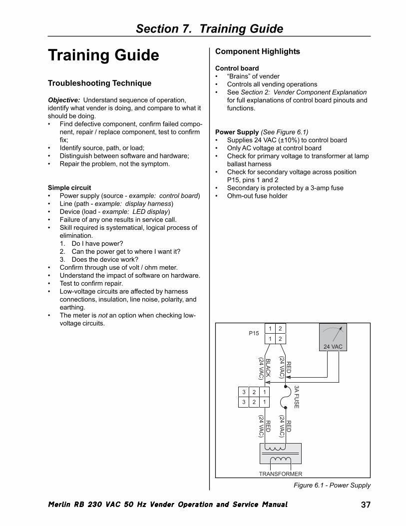
Merlin RB 230 VAC 50 Hz Vender Operation and Service ManualMerlin RB 230 VAC 50 Hz Vender Operation and Service ManualMerlin RB 230 VAC 50 Hz Vender Operation and Service ManualMerlin RB 230 VAC 50 Hz Vender Operation and Service ManualMerlin RB 230 VAC 50 Hz Vender Operation and Service Manual 37
Section 7. Training Guide
Training GuideTroubleshooting Technique
Objective: Understand sequence of operation,identify what vender is doing, and compare to what itshould be doing.• Find defective component, confirm failed compo-
nent, repair / replace component, test to confirmfix;
• Identify source, path, or load;• Distinguish between software and hardware;• Repair the problem, not the symptom.
Simple circuit• Power supply (source - example: control board)• Line (path - example: display harness)• Device (load - example: LED display)• Failure of any one results in service call.• Skill required is systematical, logical process of
elimination.1. Do I have power?2. Can the power get to where I want it?3. Does the device work?
• Confirm through use of volt / ohm meter.• Understand the impact of software on hardware.• Test to confirm repair.• Low-voltage circuits are affected by harness
connections, insulation, line noise, polarity, andearthing.
• The meter is not an option when checking low-voltage circuits.
Component Highlights
Control board• “Brains” of vender• Controls all vending operations• See Section 2: Vender Component Explanation
for full explanations of control board pinouts andfunctions.
Power Supply (See Figure 6.1)• Supplies 24 VAC (±10%) to control board• Only AC voltage at control board• Check for primary voltage to transformer at lamp
ballast harness• Check for secondary voltage across position
P15, pins 1 and 2• Secondary is protected by a 3-amp fuse• Ohm-out fuse holder
Figure 6.1 - Power Supply
BLACK
(24 VAC)
RED
(24 VAC)
P151
1
2
2
1
12
23
3
RED
(24 VAC)
RED
(24 VAC)
3A FUSE
TRANSFORMER
24 VAC
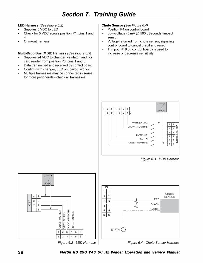
Merlin RB 230 VAC 50 Hz Vender Operation and Service ManualMerlin RB 230 VAC 50 Hz Vender Operation and Service ManualMerlin RB 230 VAC 50 Hz Vender Operation and Service ManualMerlin RB 230 VAC 50 Hz Vender Operation and Service ManualMerlin RB 230 VAC 50 Hz Vender Operation and Service Manual38
LED Harness (See Figure 6.2)• Supplies 5 VDC to LED• Check for 5 VDC across position P1, pins 1 and
4• Ohm-out harness
Multi-Drop Bus (MDB) Harness (See Figure 6.3)• Supplies 24 VDC to changer, validator, and / or
card reader from position P3, pins 1 and 6• Data transmitted and received by control board• Confirm with changer, LED on; payout works• Multiple harnesses may be connected in series
for more peripherals - check all harnesses
Chute Sensor (See Figure 6.4)• Position P4 on control board• Low-voltage (5 mV @ 500 µSeconds) impact
sensor• Voltage returned from chute sensor, signaling
control board to cancel credit and reset• Trimpot (R19 on control board) is used to
increase or decrease sensitivity
Section 7. Training Guide
Figure 6.2 - LED Harness Figure 6.4 - Chute Sensor Harness
1
2
3
4
1
2
3
4
L.E.D.
5 VDC
P1
1
1
2
2 3
3
4
4 5 6
5 6
RED
(NEU
TRAL)
BRO
WN
(CLO
CK)
GR
EEN (D
ATA)
YELLOW
(5 VDC
)
11
22
3 3
4 4
5
6
P4
BLACK
RED
CHUTESENSOR
EARTH
EARTH5
6
Figure 6.3 - MDB Harness
WHITE (24 VDC)
BROWN (NEUTRAL)
24 VDCP3
123
BLACK (RX)
RED (TX)
GREEN (NEUTRAL)
11
2 2
3 3
4 4
5 5
6 6
MD
B PERIPH
ERAL
4567
123456
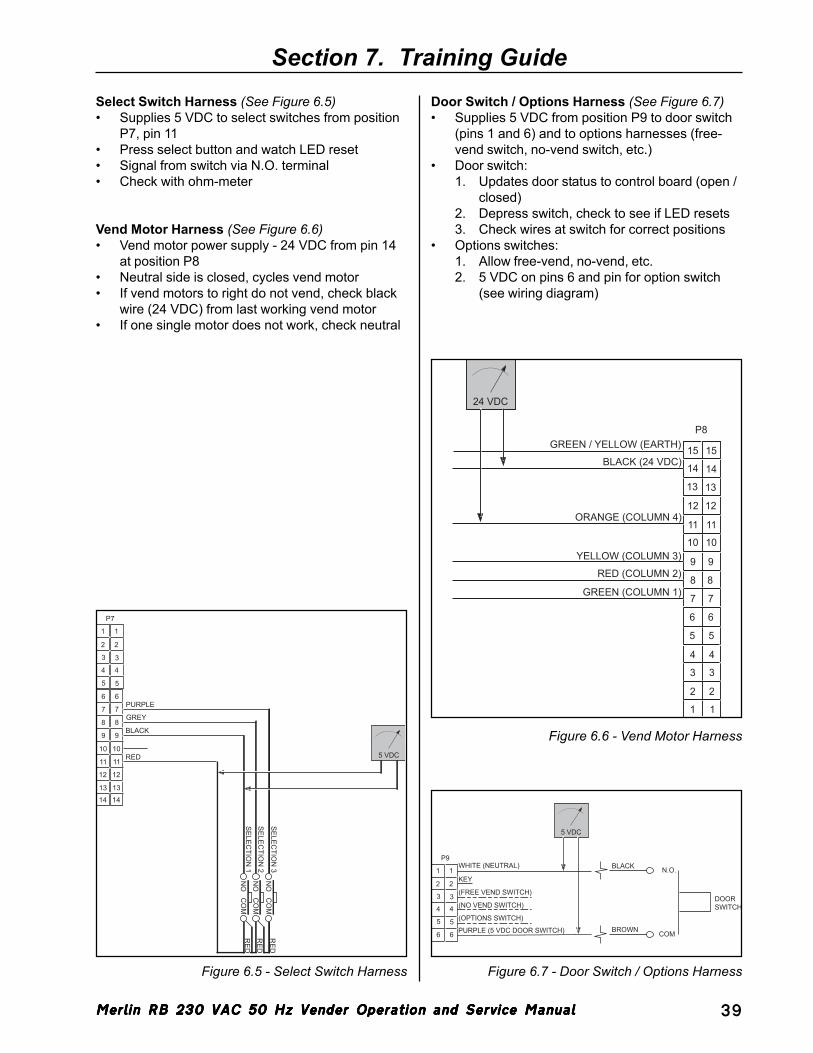
Merlin RB 230 VAC 50 Hz Vender Operation and Service ManualMerlin RB 230 VAC 50 Hz Vender Operation and Service ManualMerlin RB 230 VAC 50 Hz Vender Operation and Service ManualMerlin RB 230 VAC 50 Hz Vender Operation and Service ManualMerlin RB 230 VAC 50 Hz Vender Operation and Service Manual 39
Select Switch Harness (See Figure 6.5)• Supplies 5 VDC to select switches from position
P7, pin 11• Press select button and watch LED reset• Signal from switch via N.O. terminal• Check with ohm-meter
Vend Motor Harness (See Figure 6.6)• Vend motor power supply - 24 VDC from pin 14
at position P8• Neutral side is closed, cycles vend motor• If vend motors to right do not vend, check black
wire (24 VDC) from last working vend motor• If one single motor does not work, check neutral
Section 7. Training GuideDoor Switch / Options Harness (See Figure 6.7)• Supplies 5 VDC from position P9 to door switch
(pins 1 and 6) and to options harnesses (free-vend switch, no-vend switch, etc.)
• Door switch:1. Updates door status to control board (open /
closed)2. Depress switch, check to see if LED resets3. Check wires at switch for correct positions
• Options switches:1. Allow free-vend, no-vend, etc.2. 5 VDC on pins 6 and pin for option switch
(see wiring diagram)
Figure 6.5 - Select Switch Harness Figure 6.7 - Door Switch / Options Harness
P7
SE
LEC
TION
3N
OC
OM
RE
DS
ELE
CTIO
N 2
NO
CO
MR
ED
SE
LEC
TION
1N
OC
OM
RE
D
5 VDC
1
2
3
4
5
6
7
8
9
10
11
12
13
14
1
2
3
4
5
6
7
8
9
10
11
12
13
14
PURPLE
GREY
BLACK
RED
P9
5 VDC
WHITE (NEUTRAL)
PURPLE (5 VDC DOOR SWITCH)
N.O.
COM
DOORSWITCH
BROWN
BLACK1
2
3
4
5
6
1
2
3
4
5
6
KEY
(FREE VEND SWITCH)
(NO VEND SWITCH)
(OPTIONS SWITCH)
Figure 6.6 - Vend Motor Harness
1 1
22
33
44
55
66
77
88
99
1010
1111
1212
1313
P8
YELLOW (COLUMN 3)
RED (COLUMN 2)
GREEN (COLUMN 1)
24 VDC
1414
1515
ORANGE (COLUMN 4)
BLACK (24 VDC)
GREEN / YELLOW (EARTH)
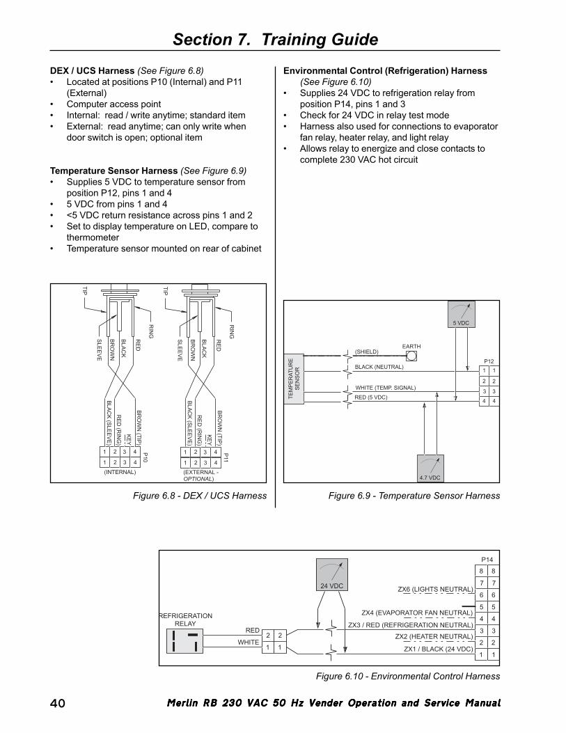
Merlin RB 230 VAC 50 Hz Vender Operation and Service ManualMerlin RB 230 VAC 50 Hz Vender Operation and Service ManualMerlin RB 230 VAC 50 Hz Vender Operation and Service ManualMerlin RB 230 VAC 50 Hz Vender Operation and Service ManualMerlin RB 230 VAC 50 Hz Vender Operation and Service Manual40
DEX / UCS Harness (See Figure 6.8)• Located at positions P10 (Internal) and P11
(External)• Computer access point• Internal: read / write anytime; standard item• External: read anytime; can only write when
door switch is open; optional item
Temperature Sensor Harness (See Figure 6.9)• Supplies 5 VDC to temperature sensor from
position P12, pins 1 and 4• 5 VDC from pins 1 and 4• <5 VDC return resistance across pins 1 and 2• Set to display temperature on LED, compare to
thermometer• Temperature sensor mounted on rear of cabinet
Section 7. Training Guide
Environmental Control (Refrigeration) Harness(See Figure 6.10)
• Supplies 24 VDC to refrigeration relay fromposition P14, pins 1 and 3
• Check for 24 VDC in relay test mode• Harness also used for connections to evaporator
fan relay, heater relay, and light relay• Allows relay to energize and close contacts to
complete 230 VAC hot circuit
Figure 6.10 - Environmental Control Harness
11
22
3 3
4 4
5 5
6 6
P14
7
8
ZX1 / BLACK (24 VDC)
ZX2 (HEATER NEUTRAL)
ZX3 / RED (REFRIGERATION NEUTRAL)
ZX4 (EVAPORATOR FAN NEUTRAL)
ZX6 (LIGHTS NEUTRAL)
11
22WHITE
RED
REFRIGERATIONRELAY
24 VDC 7
8
Figure 6.9 - Temperature Sensor HarnessFigure 6.8 - DEX / UCS Harness
11
2 2
3 3
4 4RED (5 VDC)
WHITE (TEMP. SIGNAL)
BLACK (NEUTRAL)
EARTH
TEM
PER
ATU
RE
SEN
SOR
5 VDC
4.7 VDC
(SHIELD)
P12
P10
1
1
2
2 3
3
4
4
BRO
WN
(TIP)
KEY
RED
(RIN
G)
BLACK (SLEEVE)
TIP
SLE
EV
E
RIN
G
RE
D
BLA
CK
BR
OW
N
P11
1
1
2
2 3
3
4
4
BRO
WN
(TIP)
KEY
RED
(RIN
G)
BLACK (SLEEVE)
TIP
SLE
EV
E
RIN
G
RE
D
BLA
CK
BR
OW
N
(INTERNAL) (EXTERNAL -OPTIONAL)
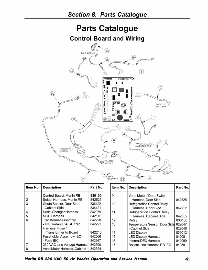
Merlin RB 230 VAC 50 Hz Vender Operation and Service ManualMerlin RB 230 VAC 50 Hz Vender Operation and Service ManualMerlin RB 230 VAC 50 Hz Vender Operation and Service ManualMerlin RB 230 VAC 50 Hz Vender Operation and Service ManualMerlin RB 230 VAC 50 Hz Vender Operation and Service Manual 41
Section 8. Parts Catalogue
Control Board and WiringParts Catalogue
CHU
TEP4
OPTI
ONS
P9
SW1
MOD
E SW
ITCH
SELE
CTIO
N SW
ITCH
ESP7
HHC 2HHC 1 P11P10DISPLAYP1HS TEMP
SENSORP2
TEMP SENSOR
P12ENV. CONTROLS
P14VEND M
OTORSP8
24 VAC
P15 MDB
P3
P16
L.E.D. DISPLAY
13
1615
14
3
TO IN-LINEFILTER
7
6TO COIN CHANGER,VALIDATOR, ETC.
TO VENDMOTORS
4
8
12
1
5
10
TO DOORSWITCH
TO SELECTSWITCHES
2
11
9
17
Item No. Description Part No.
1 Control Board, Merlin RB 8361692 Select Harness, Merlin RB 8425233 Chute Sensor, Door Side 836122
- Cabinet Side 8361214 Serial Changer Harness 8420795 MDB Harness 8421166 Transformer Assembly 842220
- UK / Ireland / Aust. / NZ 842221Harness, Fuse /
Transformer to Board 842210Fuseholder Assembly IEC 842566- Fuse IEC 842567
7 230 VAC Line Voltage Harness 8425908 Vend Motor Harness, Cabinet 842524
9 Vend Motor / Door SwitchHarness, Door Side 842525
10 Refrigeration Control RelayHarness, Door Side 842236
11 Refrigeration Control RelayHarness, Cabinet Side 842332
12 Relay 83613013 Temperature Sensor, Door Side 822047
- Cabinet Side 82204614 LED Display 83601215 LED Display Harness 84208116 Internal DEX Harness 84209917 Ballast Line Harness RB IEC 842591
Item No. Description Part No.
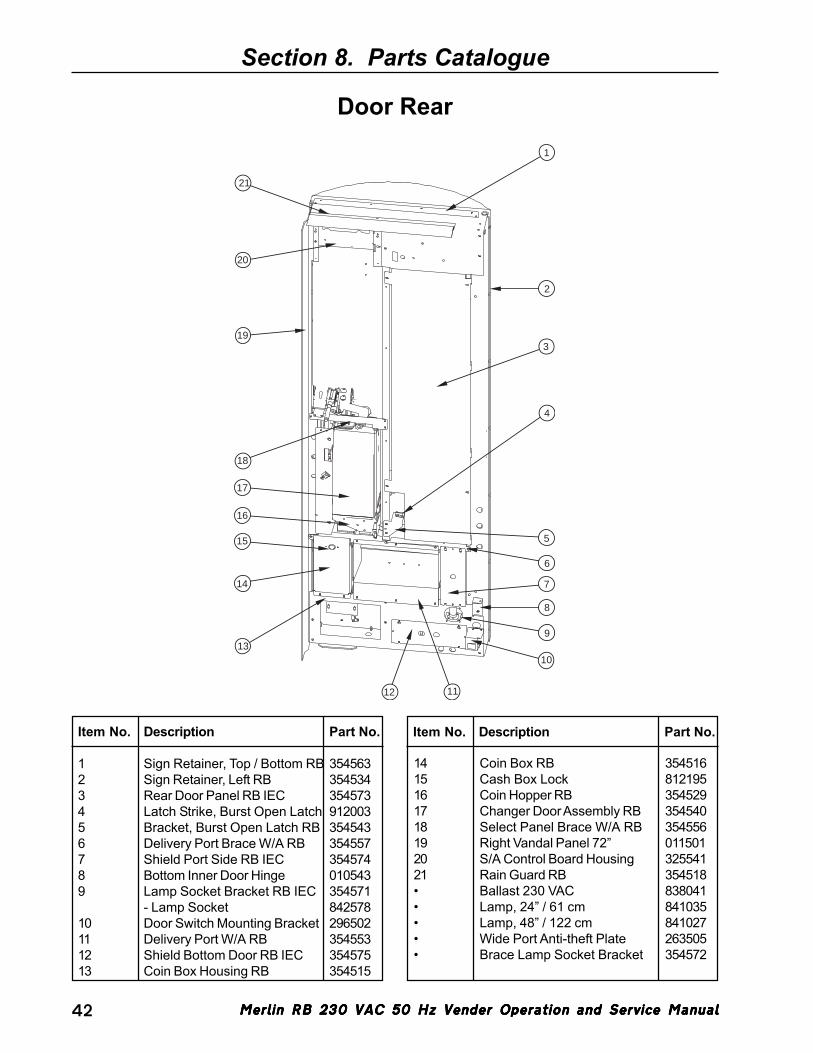
Merlin RB 230 VAC 50 Hz Vender Operation and Service ManualMerlin RB 230 VAC 50 Hz Vender Operation and Service ManualMerlin RB 230 VAC 50 Hz Vender Operation and Service ManualMerlin RB 230 VAC 50 Hz Vender Operation and Service ManualMerlin RB 230 VAC 50 Hz Vender Operation and Service Manual42
Section 8. Parts Catalogue
Door Rear
6
8
10
11
14
13
2
1
3
5
7
4
15
17
18
19
20
21
16
9
12
Item No. Description Part No.
1 Sign Retainer, Top / Bottom RB 3545632 Sign Retainer, Left RB 3545343 Rear Door Panel RB IEC 3545734 Latch Strike, Burst Open Latch 9120035 Bracket, Burst Open Latch RB 3545436 Delivery Port Brace W/A RB 3545577 Shield Port Side RB IEC 3545748 Bottom Inner Door Hinge 0105439 Lamp Socket Bracket RB IEC 354571
- Lamp Socket 84257810 Door Switch Mounting Bracket 29650211 Delivery Port W/A RB 35455312 Shield Bottom Door RB IEC 35457513 Coin Box Housing RB 354515
Item No. Description Part No.
14 Coin Box RB 35451615 Cash Box Lock 81219516 Coin Hopper RB 35452917 Changer Door Assembly RB 35454018 Select Panel Brace W/A RB 35455619 Right Vandal Panel 72” 01150120 S/A Control Board Housing 32554121 Rain Guard RB 354518• Ballast 230 VAC 838041• Lamp, 24” / 61 cm 841035• Lamp, 48” / 122 cm 841027• Wide Port Anti-theft Plate 263505• Brace Lamp Socket Bracket 354572

Merlin RB 230 VAC 50 Hz Vender Operation and Service ManualMerlin RB 230 VAC 50 Hz Vender Operation and Service ManualMerlin RB 230 VAC 50 Hz Vender Operation and Service ManualMerlin RB 230 VAC 50 Hz Vender Operation and Service ManualMerlin RB 230 VAC 50 Hz Vender Operation and Service Manual 43
Section 8. Parts Catalogue
Security Plate Assembly354520
1718
1920
2122 25
1
2
4
5
3
678
9
10
11
12
13
14
15
16
23 24
Item No. Description Part No.
1 Coin Return Lever Assembly 3545502 Screw #8-32 x 3/8” 9010113 Select Button Angle RB 3545084 Select Button Switch 8350125 Screw #6-32 x 1” T-form 9010866 Coin Chute Cover RB 3545397 Coin Chute RB 3545388 Select Button Channel RB 3545079 Select Button RB 81614110 LED Shroud 92903111 Coin Plate RB 35452312 Keps Nut #8-32 90500113 Security Plate W/A RB 354530
Item No. Description Part No.
14 Security Plate Decal (English) 83160815 LED Lens 91603216 1/4-20 x 1” T-bolt 90103717 Bushing Retainer 33755618 Coin Return Bushing 80305919 Coin Return Button 80303120 LED Window 81512121 LED Display 83601222 T-handle Brace 33758323 Keps Nut 1/4-20 90500224 T-handle Housing 81219025 T-handle Assembly 812176
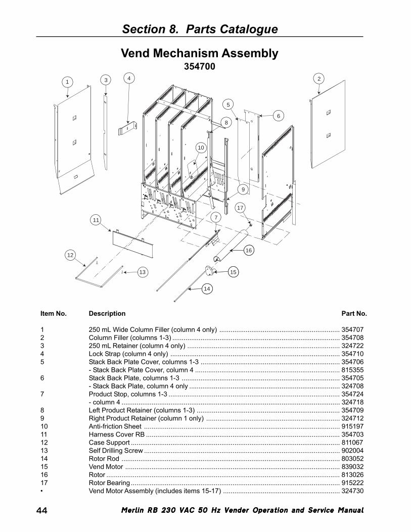
Merlin RB 230 VAC 50 Hz Vender Operation and Service ManualMerlin RB 230 VAC 50 Hz Vender Operation and Service ManualMerlin RB 230 VAC 50 Hz Vender Operation and Service ManualMerlin RB 230 VAC 50 Hz Vender Operation and Service ManualMerlin RB 230 VAC 50 Hz Vender Operation and Service Manual44
Section 8. Parts Catalogue
Vend Mechanism Assembly354700
11
14
15
16
17
7
13
6
5
8
9
10
12
1 3 4 2
Item No. Description Part No.
1 250 mL Wide Column Filler (column 4 only) ................................................................ 3547072 Column Filler (columns 1-3) ......................................................................................... 3547083 250 mL Retainer (column 4 only) ................................................................................. 3247224 Lock Strap (column 4 only) .......................................................................................... 3547105 Stack Back Plate Cover, columns 1-3 .......................................................................... 354706
- Stack Back Plate Cover, column 4 ............................................................................. 8153556 Stack Back Plate, columns 1-3 .................................................................................... 354705
- Stack Back Plate, column 4 only ................................................................................ 3247087 Product Stop, columns 1-3 ........................................................................................... 354724
- column 4 .................................................................................................................... 3247188 Left Product Retainer (columns 1-3) ............................................................................ 3547099 Right Product Retainer (column 1 only) ....................................................................... 32471210 Anti-friction Sheet ........................................................................................................ 91519711 Harness Cover RB ....................................................................................................... 35470312 Case Support ............................................................................................................... 81106713 Self Drilling Screw ........................................................................................................ 90200414 Rotor Rod .................................................................................................................... 80305215 Vend Motor .................................................................................................................. 83903216 Rotor ............................................................................................................................ 81302617 Rotor Bearing ............................................................................................................... 915222• Vend Motor Assembly (includes items 15-17) .............................................................. 324730

Merlin RB 230 VAC 50 Hz Vender Operation and Service ManualMerlin RB 230 VAC 50 Hz Vender Operation and Service ManualMerlin RB 230 VAC 50 Hz Vender Operation and Service ManualMerlin RB 230 VAC 50 Hz Vender Operation and Service ManualMerlin RB 230 VAC 50 Hz Vender Operation and Service Manual 45
Section 8. Parts Catalogue
Inner Door Assembly
14
1
2
3
4
5
6
3
78
9
10
11
12
13
14
15
Item No. Description Part No.
1 Top Inner Door Hinge W/A ........................................................................................... 0105202 Keps Nut #8-32 ............................................................................................................ 9050013 Self Drilling Screw ........................................................................................................ 9020014 Rivet, 1/8” .................................................................................................................... 9080025 Cable Clamp, 1” ........................................................................................................... 9160046 Burst Open Latch ......................................................................................................... 8120027 Inner Door Gasket RB ................................................................................................. 8155678 Port Door Rod .............................................................................................................. 8110289 Port Door ..................................................................................................................... 81519210 Elastic Stop Nut ........................................................................................................... 90500611 Port Door Frame .......................................................................................................... 81519112 Screw, 1/4-20 x 1” with Serrations ............................................................................... 90100313 Bottom Inner Door Hinge ............................................................................................. 01055014 Inner Door Bushing ....................................................................................................... 81502615 Inner Door Assembly .................................................................................................... 354610• Loading Label RB (English) .......................................................................................... 931610• Controller Instruction Label RB (English) ....................................................................... 931611• Interconnect Label RB IEC ........................................................................................... 931696• Inner Door Lock with Key .............................................................................................. 812055
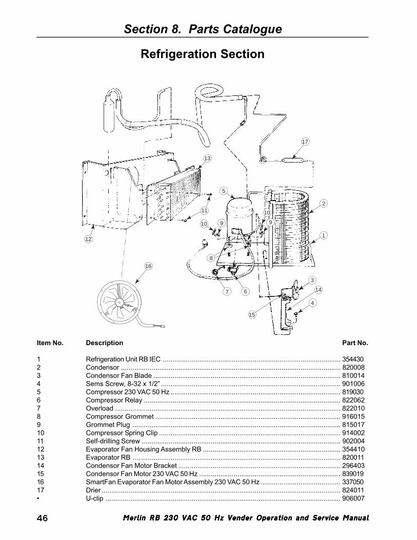
Merlin RB 230 VAC 50 Hz Vender Operation and Service ManualMerlin RB 230 VAC 50 Hz Vender Operation and Service ManualMerlin RB 230 VAC 50 Hz Vender Operation and Service ManualMerlin RB 230 VAC 50 Hz Vender Operation and Service ManualMerlin RB 230 VAC 50 Hz Vender Operation and Service Manual46
Section 8. Parts Catalogue
Refrigeration Section
17
2
3
413
OPTIONAL
7 6
8
10 9 9
1011
13
12
5
14
15
16
1
Item No. Description Part No.
1 Refrigeration Unit RB IEC ............................................................................................. 3544302 Condensor ................................................................................................................... 8200083 Condensor Fan Blade .................................................................................................. 8100144 Sems Screw, 8-32 x 1/2” .............................................................................................. 9010065 Compressor 230 VAC 50 Hz ......................................................................................... 8190306 Compressor Relay ....................................................................................................... 8220627 Overload ...................................................................................................................... 8220108 Compressor Grommet ................................................................................................. 9160159 Grommet Plug ............................................................................................................. 81501710 Compressor Spring Clip ............................................................................................... 91400211 Self-drilling Screw ........................................................................................................ 90200412 Evaporator Fan Housing Assembly RB ........................................................................ 35441013 Evaporator RB ............................................................................................................. 82001114 Condensor Fan Motor Bracket ..................................................................................... 29640315 Condensor Fan Motor 230 VAC 50 Hz .......................................................................... 83901916 SmartFan Evaporator Fan Motor Assembly 230 VAC 50 Hz .......................................... 33705017 Drier ............................................................................................................................. 824011• U-clip ........................................................................................................................... 906007
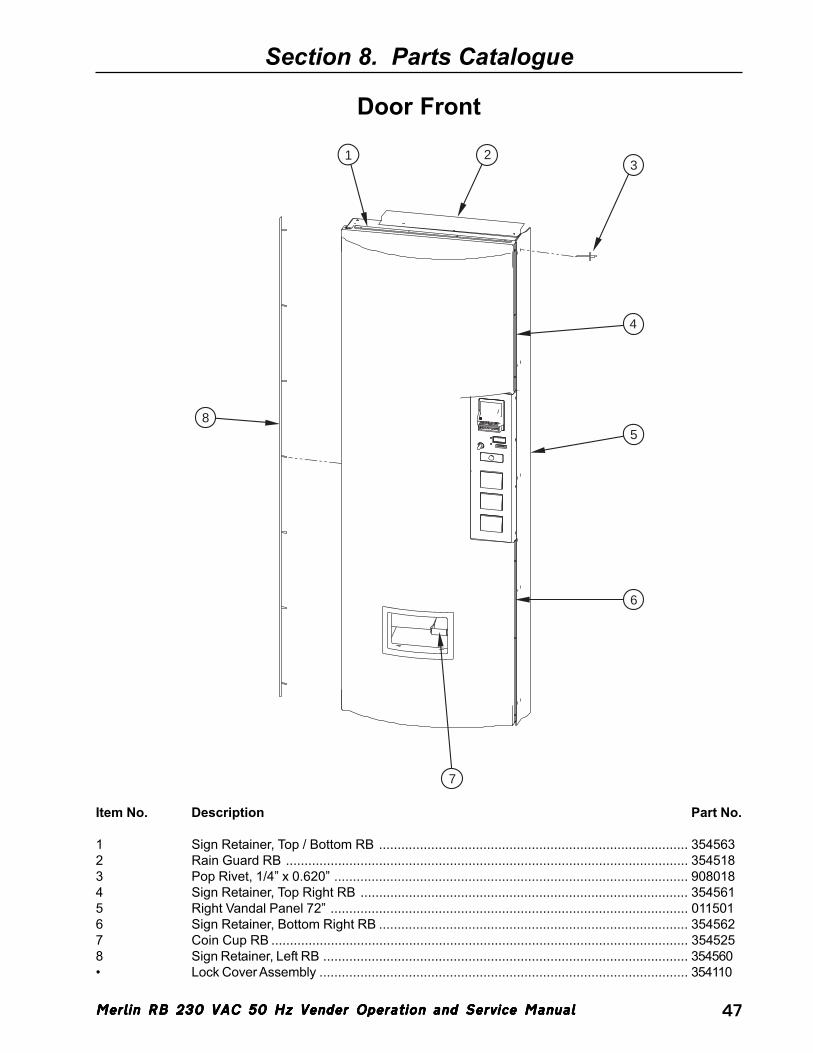
Merlin RB 230 VAC 50 Hz Vender Operation and Service ManualMerlin RB 230 VAC 50 Hz Vender Operation and Service ManualMerlin RB 230 VAC 50 Hz Vender Operation and Service ManualMerlin RB 230 VAC 50 Hz Vender Operation and Service ManualMerlin RB 230 VAC 50 Hz Vender Operation and Service Manual 47
Section 8. Parts Catalogue
Door Front
8
1 23
4
5
6
7
Item No. Description Part No.
1 Sign Retainer, Top / Bottom RB ................................................................................... 3545632 Rain Guard RB ............................................................................................................ 3545183 Pop Rivet, 1/4” x 0.620” ............................................................................................... 9080184 Sign Retainer, Top Right RB ........................................................................................ 3545615 Right Vandal Panel 72” ................................................................................................ 0115016 Sign Retainer, Bottom Right RB ................................................................................... 3545627 Coin Cup RB ................................................................................................................ 3545258 Sign Retainer, Left RB .................................................................................................. 354560• Lock Cover Assembly ................................................................................................... 354110
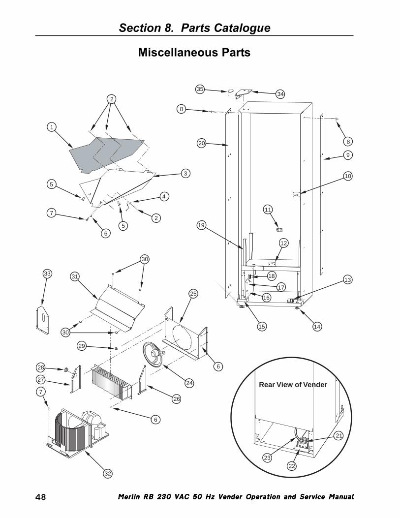
Merlin RB 230 VAC 50 Hz Vender Operation and Service ManualMerlin RB 230 VAC 50 Hz Vender Operation and Service ManualMerlin RB 230 VAC 50 Hz Vender Operation and Service ManualMerlin RB 230 VAC 50 Hz Vender Operation and Service ManualMerlin RB 230 VAC 50 Hz Vender Operation and Service Manual48
Miscellaneous Parts
Section 8. Parts Catalogue
Rear View of Vender
17
18
19
20
21
2223
25
6
24
26
6
32
7
27
28
29
31
30
33
30
1
2
3
4
25
6
7
5
8
8
9
10
11
12
14
13
15
16
3435
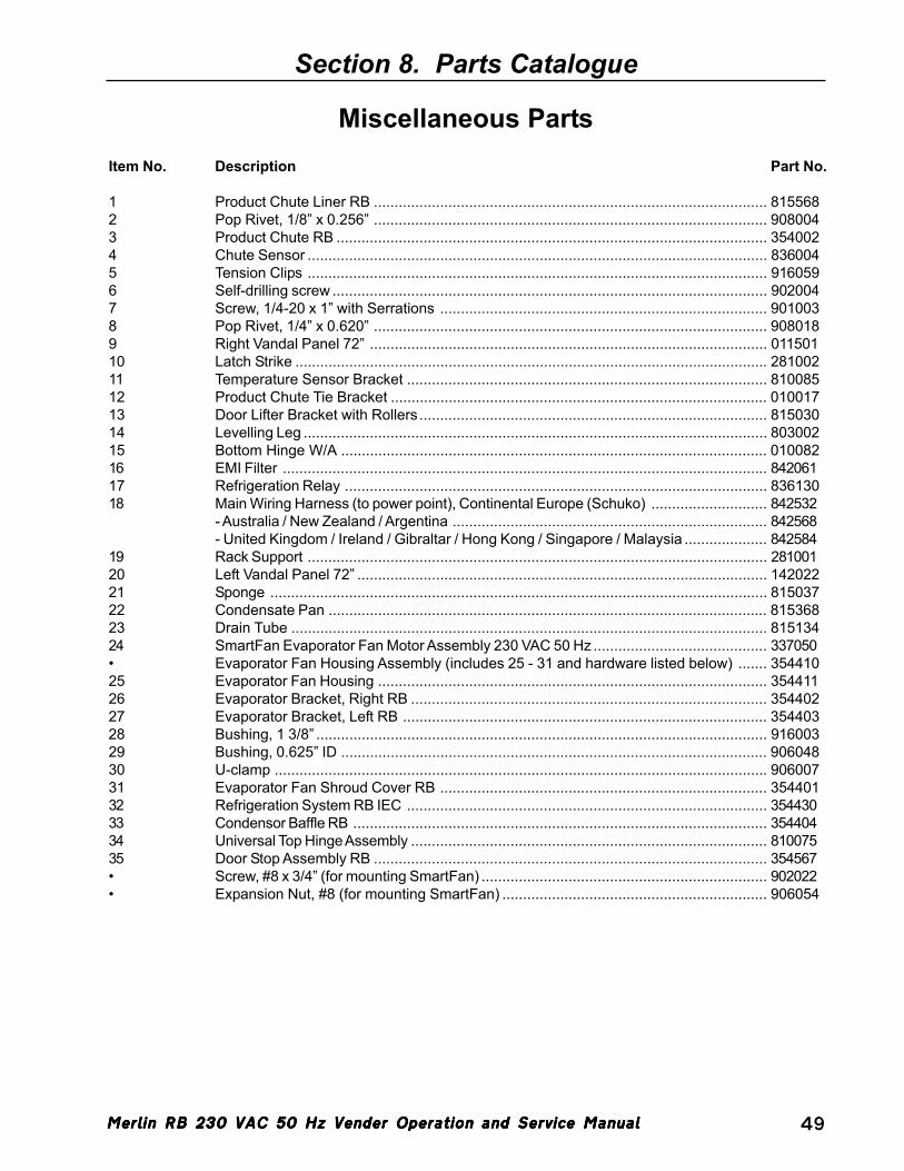
Merlin RB 230 VAC 50 Hz Vender Operation and Service ManualMerlin RB 230 VAC 50 Hz Vender Operation and Service ManualMerlin RB 230 VAC 50 Hz Vender Operation and Service ManualMerlin RB 230 VAC 50 Hz Vender Operation and Service ManualMerlin RB 230 VAC 50 Hz Vender Operation and Service Manual 49
Section 8. Parts Catalogue
Miscellaneous PartsItem No. Description Part No.
1 Product Chute Liner RB ............................................................................................... 8155682 Pop Rivet, 1/8” x 0.256” ............................................................................................... 9080043 Product Chute RB ........................................................................................................ 3540024 Chute Sensor ............................................................................................................... 8360045 Tension Clips ............................................................................................................... 9160596 Self-drilling screw ......................................................................................................... 9020047 Screw, 1/4-20 x 1” with Serrations ............................................................................... 9010038 Pop Rivet, 1/4” x 0.620” ............................................................................................... 9080189 Right Vandal Panel 72” ................................................................................................ 01150110 Latch Strike .................................................................................................................. 28100211 Temperature Sensor Bracket ....................................................................................... 81008512 Product Chute Tie Bracket ........................................................................................... 01001713 Door Lifter Bracket with Rollers .................................................................................... 81503014 Levelling Leg ................................................................................................................ 80300215 Bottom Hinge W/A ....................................................................................................... 01008216 EMI Filter ..................................................................................................................... 84206117 Refrigeration Relay ...................................................................................................... 83613018 Main Wiring Harness (to power point), Continental Europe (Schuko) ............................ 842532
- Australia / New Zealand / Argentina ............................................................................ 842568- United Kingdom / Ireland / Gibraltar / Hong Kong / Singapore / Malaysia .................... 842584
19 Rack Support ............................................................................................................... 28100120 Left Vandal Panel 72” ................................................................................................... 14202221 Sponge ........................................................................................................................ 81503722 Condensate Pan .......................................................................................................... 81536823 Drain Tube ................................................................................................................... 81513424 SmartFan Evaporator Fan Motor Assembly 230 VAC 50 Hz .......................................... 337050• Evaporator Fan Housing Assembly (includes 25 - 31 and hardware listed below) ....... 35441025 Evaporator Fan Housing .............................................................................................. 35441126 Evaporator Bracket, Right RB ...................................................................................... 35440227 Evaporator Bracket, Left RB ........................................................................................ 35440328 Bushing, 1 3/8” ............................................................................................................. 91600329 Bushing, 0.625” ID ....................................................................................................... 90604830 U-clamp ....................................................................................................................... 90600731 Evaporator Fan Shroud Cover RB ............................................................................... 35440132 Refrigeration System RB IEC ....................................................................................... 35443033 Condensor Baffle RB .................................................................................................... 35440434 Universal Top Hinge Assembly ...................................................................................... 81007535 Door Stop Assembly RB ............................................................................................... 354567• Screw, #8 x 3/4” (for mounting SmartFan) ..................................................................... 902022• Expansion Nut, #8 (for mounting SmartFan) ................................................................ 906054
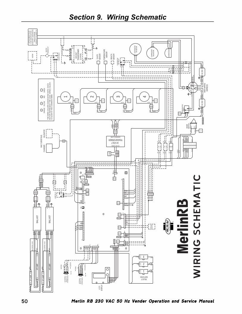
Merlin RB 230 VAC 50 Hz Vender Operation and Service ManualMerlin RB 230 VAC 50 Hz Vender Operation and Service ManualMerlin RB 230 VAC 50 Hz Vender Operation and Service ManualMerlin RB 230 VAC 50 Hz Vender Operation and Service ManualMerlin RB 230 VAC 50 Hz Vender Operation and Service Manual50
Section 9. Wiring Schematic
BRO
WN
BLAC
K
RED
NONC
NONC
RED
REDRED
RED
7 6 5 4 3 2 1
BLAC
K
RED
KEY
BRO
WN
BLAC
K
RED
KEY
21
2121
21
BLAC
K
ORA
NGE
YELL
OW
RED
GRE
EN
BLAC
K
ORA
NGE
YELL
OW
RED
LOAD
LOAD
43
2
48" L
AMP
24" L
AMP
BRO
WN
BLUE
BRO
WN
2X
BLUE
2X
BRO
WN
BLUE
BRO
WN
BLUE
BALL
AST
BRO
WN
BRO
WN
BLUE
BRO
WN
BLUE
LINE
L1 NBR
OW
NBL
UEFI
LTER
LINE
BLUE
BRO
WN
BLUE
BRO
WN
FILT
ER
L1
48" L
AMP
24" L
AMP
BALL
AST
NEUTRAL
1615
1716
65
NEUTRAL
SENS
OR
HEAL
TH
REDWHITE
BLACKKEY
P21
23
47 6 5
KEY
BLUE
NEUTRAL
NEUTRAL
NEUT
RAL
NEUTRAL
220/
240V
AC
DC
24v
DC
24v
DC
24v
DC
24v
RED
BLAC
K1 2 3
1 2 3* FUS
E
BLUE
22
11
GRN/YEL
BLACK
ORANGE
KEY
YELLOW
RED
GREEN
P1
P15 21
220/240VAC (LINE)
24 VAC (LOAD)
ORA
NGE
YELL
OW
RED
GRE
EN
43
21
N L1
L1
BLACK
WHITE
BLACK
WHITE
HT2
HT1
FN2
FN1
GREEN
RED YELLOW ORANGEBLAC
K
BLAC
K
BLAC
K
BLAC
K
RED
BLACK
RED
BLACK
RED
BLACK
RED
BLACK
ST2
ST1
GRE
EN
ST2
ST1
FT1
ZX3
FN2
FN1
FT3
ZX4
FT2
ZX5
HT2
HT1
REDBLACK
ZX6
FT4
FT4
FT3
FT2
FT1
ZX2
ZX2
ZX2
ZX1
ZX6
KEY
ZX4
ZX3
ZX5
ZX1
GRE
ENRE
DBL
ACK
KEY
BRO
WN
WHI
TE
PURPLE
GREY
BLACKRED
KEY
PURPLE
GREY
BLACK
RED
KEY
KEY
PURPLE
WHITE
YELL
OW
YELLOWGREENBROWN
RED
RED
BRO
WN
GRE
EN
1
BRO
WN
BLAC
K
RED
BRO
WN
BLACK
WHITERED
FAN
RELA
YEV
APO
RATO
R
2 112
2 112
2 112
HEAT
ER R
ELAYTH
ERM
OST
ATHE
ATER
HEAT
ER
220
VOLT
(1.0
KVA
)TR
ANSF
ORM
ER
SENS
OR
CHUT
E
SENS
OR
TEM
PERA
TURE
FAN
MO
TOR
EVAP
ORA
TOR
FAN
MO
TOR
COM
PRES
SOR
COM
PRES
SOR
HAR
NESS
MAI
N W
IRIN
G
R
ELAY
REFR
IGER
ATIO
N
SWITCHES SELECT
122 1
4321
987654321
987654321
222
222
11
11
11
COUN
TER
IMPU
LSE
TRANSFORMER 24 VOLT
CHAN
GER
VALI
DATO
R
MUL
TI-D
ROP
BUS
44
33
22
11
3
2
1
C
C
CNONC
SW1
LED1
R19
P4P3
P8P1
4
P7
P9
P12
P11
P10
87
65
43
21
43
21
7654321
1514
1312
1110
98
76
54
32
1
1413
1211
109
87
66
55
44
33
22
11
12
34
4 43 32 21 1 4 3 2 1
LAM
P RE
LAY
DISP
LAY
L.E
.D.
SWIT
CH D
OO
R
PURP
LEW
HITE
WHI
TE
PURP
LE
DC5v
NC NO COM
Merlin
WIR
ING
SC
HEM
AT
IC
R
TIP
SLE
EV
E
RIN
G
TIP
SLE
EV
E
RIN
G
DC
5V
DC
5VD
C24
VD
C24
VD
C24
V
AC
24V
DC
24V
DC
5VD
C5V
PH
ON
EJA
CK
DE
X/U
.C.S
.IN
TE
RN
AL
PH
ON
EJA
CK
DE
X/U
.C.S
.E
XT
ER
NA
L
DC
24V
RE
D
BLU
E 2
XR
ED
BLU
E 2
X
JUM
PE
R, R
ED
BLU
EB
LUE
RE
D
RE
DB
LUE
BLU
E
BT
MT
OP
TO
PB
TM
RE
D
BLU
E 2
XR
ED
BLU
E 2
X
JUM
PE
R, R
ED
BLU
EB
LUE
RE
D
RE
DB
LUE
BLU
E
BT
MT
OP
TO
PB
TM
2121
2121
2121
L N L N
1 2 3 4 5 6 7 1 2 3 4 5 6 7
AP
PLI
CA
BLE
PLU
G
FO
R D
ES
TIN
AT
ION
C
OU
NT
RY
220
/240
VA
C
SIN
GLE
PH
AS
E
W/E
AR
TH
PO
WE
R IN
IS A
LWA
YS
TH
E C
OM
MO
N W
IRE
.M
OT
OR
RE
PR
ES
EN
T T
HE
LE
AD
WIR
ES
. BLA
CK
T
HE
WIR
E C
OLO
RS
AS
SO
CIA
TE
D W
ITH
EA
CH
Printed in theUnited States of America
P/N 833090Rev. A (May 2006)Royal Vendors, Inc.
R
Imprimé auxEtats-Unis d’Amérique