Embed Size (px)
Citation preview


ACKNOWLEDGEMENTS
· • Technical Advisory Panel
Keith ferguson
Phil Tonkin
John Olszewski
• Projed Coordinator
James Fergus, P.E., Construction Staff Engineer
e Course. Development
Rev. 1980
Gary D. Taylor, P.E., Construction Staff Engineer
Gene Russell, l.C.C.

TABLE OF CONTENTS
Chapter Page
Basic Plan Reading Information 1 - 1
2 Typical Cross Sections 2- 1
3 Highway Alignment 3 - 1
4 Construction Preparations 4 - 1
5 Grading 5 - 1
6 Drainage 6- 1
7 Paving 7- 1
8 Bridges 8 - 1
Appendix Page
A Definition of Terms A-1
B The Construction Contract B- 1
c Right-of- Way c- 1

This is a preparation chapter which will acquaint you with some basic information and procedures used on most plan sheets.
MEANING OF DIFFERENT VIEWS
Most objects have a different appearance when viewed from different angles. A top view usually is quite different from a side view.
Because objects are shown on highway plans from several different views, you should be able to recognize each view and understand
what it means.
The three basic views are:
1. PLAN VIEW (or top view)
2. PROFILE VIEW (or elevation view)
3. CROSS SECTION VIEW
A PLAN VIEW is a view from directly above an object. You are looking DOWN on the object. All dimensions are horizontal.
A PROFILE VIEW is a view from the side of an object. Di.mensions are either vertical or horizontal.
A CROSS SECTION VIEW is a view of the inside of an object as if it had been cut open.
,_,

• The following examples illustrate the. meaning of the three basic views:
A
1-2
PLAN VIEW,
PROFILE VIEW'
Fig. 1-1
A I

CROSS SECTION A-A I
Fig. 1-2
On highway plans, ·the PLAN VIEW shows the highway centerline and all existing and proposed features in relation to it; the PROFILE
VIEW shO-Ws the side view of the highway centerline, and the CROSS SECTION VIEW shows the highway as if it had been cut at right
angles across the highway centerline looking ahead.
TYPES OF HIGHWAY PLAN SHEETS AND SUPPLEMENTAL DATA
Listed below are two typical plan sheet indexes showing the several types of plan sheets included in contract plans. Most of them
have drawings showing different views of things to be built. Some plan sheets have only notes ·or. listings of materials needed.
Standard symbols are used to help you recognize different objects.
ROAD PLANS
Title Sheet
PI an of Project Sheet
Typical Cross Section Sheet
Note Sheet
Stage Construction Sheet
Removal Sheet
Plan and Profile Sheet
Special Details Sheet
Quantity Sheet
BRIDGE PLANS
Title Sheet
Quantity Sheet
General Plan of Site Sheet
Lag of Boring Sheet
General PI an of Structure Sheet
Abutment Detai Is Sheet
Pier Details Sheet
Structural Steel Detail Sheet
Superstructure Detai Is Sheet
Steel Reinforcement Detai Is Sheet
1-3
SUPPLEMENTAL DATA
Special Provisions (Proposal)
Supplemental Specifications
Project Plans & Drawings
Standard Plans
Standard Specifications
Construction Manuals
Inspection Checklist
Traffic Manual

-... t
STANDARD PLANS and R.O.W. PLANS are not included in contract plans, but are used in conjunction with them.
Let's take a look at the main types of plan sheets in a set of road plans. The purpose here is to understand the basic description of
each type of plan sheet. You will study them in greater detail in the other chapters. The description of each of the plan sheets in a
set of bridge plans is covered in Chapter 8. The sheet numbers mentioned in the discussion refer to your Construction Plans Book.
TITLE SHEET
'The front cover of a set of plans is the Title Sheet. It identifies the project and shows the location on the map, along with other in·
formation. The title sheet serves the following main purposes:
1. Shows the location of the project on a map of the area in which the work is located.
2. Provides an index for the sheets that make up a set of plans.
3. Provides a note in the upper right hand corner stating which edition of the Michigan Deportment of Transportation Specifi
cations is to be used.
4. The standard signature block for the Division, Departmental, and Federal Highway Administration approval is located in
the lower right hand comer. Above the space for signatures is shown the type of work involved in this contract, •OS:
CONTRACT FOR- G & D.S. Dual 36'- Cont. Rein!. Cone. Pav't., 24' Cone. Pov't., 16' Cone. Ramp & Vari.
Width Cone. Rd., Util. Alter., and Bridges.
5. Provides the project identification numbers, .structure numbers and traffic data.
PLAN OF PROJECT SHEET
This is a composite Plan and Profile Sheet for the entire length of the project.
1-4

TYPICAL CROSS SECTION SHEET
The various cross sections to be used in constructing the highway project ore drawn on the Typical Cross Section Sheets. They show
the different layers of surfacing and the shape of the side slopes and ditches. Many dimensions are aiven for construction details and notes containing information about the typical section.] Typical Cross Sections will be covered in detail in Chapter 2.
NOTE SHEET
Some instructions for constructing highways and bridges are best given in the form of notes. These general notes along with a list of
Standard Plans applying to the job, Supplemental Specifications, Special Provisions, Public Utility Notes, and Miscellaneous
Quantities are shown on the Note Sheet. Miscellaneous Quantities are items which apply throughout the project and are not detailed
or included on the plan and profile sheets.
STAGE CONSTRUCTION SHEET
These. sheets show the order in which construction is to progress. In most cases, stage construction is done to maintain traffic while
the construction is being done. Therefore, the stage construction sheets may also include maintaining traffic information, traffic
signing, .and any temporary roads, bridges, ·or ramps that ore needed. ·The method of maintaining traffic and how it is to be paid lor.
will usually be incorporated in the proposal.
REMOVAL SHEET
In very congested urban areas, removal sheets may be necessary. These sheets show the existing trees, houses, bui !dings, structures,
roods, utilities, and anything that may have to be removed to make way lor construction. Separate sheets are required to clearly show
the removal work and to simplify the rood plans.
The new r?adway alignment is usually superimposed upon the existing roadway to show the relationship of the old to the new.
1-5

PLAN AND PROFILE SHEET
These sheets show construction details of the highway from two different views. The top half of the sheet shows the highway plan
view and the bottom hall of the sheet shows the highway profile view. Sometimes the plan view and profile view are shown on separate
sheets for the purpose of clarity in the presentation of details, in which case the Plan Sheet comes first followed by the corresponding
profile sheet.
=x::= 0 ~'""" . c
I j
' ~ ·_ ~
"
- - -- - _. <:>:m>r<G a. ~
-~,..<:--~-: ···:-~··: • i .
.: 1
)'
. :· .. :-i·
1 I Fig.l-3 _,
It is good plan reading practice always to determine the orientation of the plan view. This is done by looking at the directional arrow
which points to North on Construction Plans.
1-6

I
I
I I '
\
I
l
!
l
SPECIAL DETAILS SHEET
During the course of construction, certain items will appear which will require special detail drawings. These details are designed and
incorporated into the plans. Some of the most common special details encountered are drainage structures other than culverts, ,special
manholes, water lines, layouts of intersections, retaining walls, miscellaneous sign connections, •and large scale drawings of special
features amplified over and above what can ordinarily be shown on the standard plan sheet.
QUANTITY SHEET
The highway designer prepares estimates of materials needed and work that the contractor is to perform. These estimates are sum
marized on the Quantity Sheet. The estimated quantities are listed under the heading AS PER PLANS. When the work is performed
by the contractor, ,the actual quantities will be listed under the heading AS CONSTRUCTED. Quantity sheets may also be used
to identify the location of an item to be used:
STANDARD PLANS
Construction details which are the same for all projects are drawn on sheets which are placed together in a Plan Book entitled
"Road Standard Plans and Standard Guides." Sometimes one or more standard sheets are included in the Road Plans. Look over the
Index to Standard Plans to get an idea of the items which are included in the Standard Plans.
RIGHT OF WAY PLANS
A separate set of plans is required to cover right of way details. Such plans indicate properties to be purchased either in whole or
part, data from which legal descriptions may be made, type of improvement contained within right of way parcels, and the expressway
plan including service roads and ramps in correct relationship to properties. Right of way plans are used by agents in making property
purchases, lor court actions when necessary "Ond lor record purposes. These plans are also available for use by construction personnel
to resolve right of way problems during construction.
MISCELLANEOUS SHEETS
These sheets would include all miscellaneous information such as project control data, location map, drainage map, mass ordinate, ,and
control witness information.
1-7

ABBREVIATIONS AND TOPOGRAPHIC SYMBOLS
Frequently it is necessary to abbreviate words on plan sheets. Also, numerous symbols are used on plan sheets to represent existing
topography, property lines, and objects to be built. For uniformity and clarity of understanding, standard abbreviations and symbols
have been adopted by the Department. The list below is taken from Fig. 1-24, Page 1-73 of the Construction Manual.
ABBREVIATIONS AND TOPOGRAPHIC SYMBOLS
B.M ........... Bench Mark B.S ............ Backs/ope C. 8 ............ Catch Basin C.A.S. ........ Carr. Aluminum Pipe C.S.P ......... Carr. Steel Pipe €.............. Centerline C. &G........ Curb and Gutter Cone .......... Concrete C.R.C.P ..... Cant Rein Cone. Pavt. Cu/v ........... Culvert D ............... Degree of Curve A .............. Delta Angle Dr .............. Drive
Sewer 1s1zEJ M.H. 1s1zEJ CB. =========()=====-¥= Telephone Cable M. H. ------ ~
Telegraph Cab:.cl_e __ M.H. (!)
Power Cable M. H. ----------- ----@--Gas Line M. H. ';!:lve - - - - - :::-IJ- - -v-
Cap, Drip
Steam Line Valve
--·----@-Water Line ~Cap. Meter -- -®--- ---([)--
M.H. Valve Hyd
Railroad
Light Post or Flood Light
£ .............. External M. H ........... Manhole Ex ............. Existing M.D.S.H. ... Mich.DeptState Highways F. L .......... Flowline Pavt.. ........ Pavement F.S. ........... Front Slope P. C ........... Point of Curvature Ftg ............ Footing P.l ............. Point of Intersection G.R ........... Guard Rail P. L. .......... Property Line Hdwl... ...... Headwall P. 0. CT. .... Point on Curve Tangent H./.. .......... Height Instrument P. 0. T.. ...... Point on Tangent H.W .......... High Water P. T. ........... Point of Tangency L. ............ Length Curve P.P ............. Power Pole L W .......... Low Water R ............... Radius M. ............ Middle Ordinate Distance R. C P. ........ Reinforced Cone. Pipe M.B .......... Mail Box R. 0. W ....... Right of Way
R.R. or Traffic Signal
* Business Bldg.
Gasoline Pump 0 R.R. Switch Box =- r-----------l 'Telephone Pole Cemetery ' Gem. + ' -<>- ' ' Trolley Pole L---------..J + Power Pole
' Fence -X X X-
Guy Pole • Stone (;)C'OO coeo === oooo Police Call 0 Hedge ~>a::::::::::-c:.:.;::c.:>c::::a:::::;r
Fire Call [SJ Guard Rail Mail Box rn 0 Decidous
Trees House /E) Barn 0 Conifer
* Garage @] Shed 0 Entering .......--....~ rr--v-v--~
EJ 0 Woods, Brush Leaving
Church School ~'-.../~~
Post Office E] Town Hall EJ Tile or Pipe "-----=~· 1---Hdwl. /
Fig. 1-4
1-8
San.S. ........ Sanitary Sewer St.S. .......... Storm Sewer S. W ............ Sidewalk T. .............. Tangent Length of CurVE TelP. ......... Telephone Pole T. L. .......... Trunk Line T.P. ........... Turning Point U.S.G.s. .. :. U.S. Geological Survey Vit ............ Vitrified W. $. ........... Water Service W. T. ....... _.. Water Table
Stream
Lake~ Marsh ~-lit<. ~
. ~sec. cor. Sect1on Lme I """'-Q---7¢--- ~.;::::--1 /8 cor. l % cor.
Drive
Curb or C&G
Dr. Return~ Removing Old Pavt ~
Removing Sidewalk W#&
PROJECT IDENTIFICATION BOX
This box is located in the upper right hand corner of each plan sheet in a set of road plans.
Fig. 1-5
In a set of bridge plans, the bridge identification number is located in the lower right hand corner of the title bloc;k on each plan sheet.
Example: 50.1 of 82021, which means Structure # 1 of Control Section 82021.
PROJECT NUMBER
Federal Aid pr<>jects are identified by the Federal Highway Administration with a series of letters and numbers. A typical federal
project looks like this: 1-94-5 (119) 194. Here's what it means:
The letter prefix (in this case 'I') is the Federal Project Designation indicating the type of highway system (primary, ·Secondary, inter
state, ·etc.) and the source of funds.
The first number (in the example, .'94') is the highway Route Number. Even number routes run East and West and odd number routes
run North and South.
The second number ('5') is the Program Section. They change at major intersections rather than district boundaries.
1-9

The third number (in parenthesis '119') is the Agreement Number. It represents a budgetary agreement between the Department and
the Federal Highway Administration.
The final number '194' in the example) is the Mileage Number. Michigan highways ore numbered in miles from west to east and from
south to north. The Mileage Number helps to determine the distance in miles from the Western or Southern state border to the beginning
of the project.
The State Number for the above project is I 82021-05126A.
The letter prefix is the State Project Designation indicating the type of highway system and source of funds.
The first group of numbers is the-Control Section.· The first two numbers indicate the county and the last three the location within
the county. In the example, 82 represents Wayne County since Wayne is 82 on the alphabetical list of the 83 counties in Michigan.
The second group of numbers is the Job Number. This number is assigned to the project by the Programming Section of the Depart
ment. The letter at the end of the job number indicates the state of development of the project. The 'A' indicates the project is
in Construction.
1-10

PROJECT LETTER DESIGNATIONS
The following is a list of Federal and State project letter designations.
STATE PROJECT LETTER DESIGNATION
Is BUI, BIU F, RF u MU PMS RS RSS cs OS M MS MB MBR MJT MBD MCB MTB
FEDERAL PROJECT LETTER DESIGNATION
I
lUI F, RF u M PMS RS RS S, RS OS
1-11
DESCRIPTION
Interstate Routes Interstate Safety Interstate with Urban Funds Primary Routes Urban - Primary Route Metro Urban System Pavement Marking Rural - Secondary Rural -State Secondary County Secondary Routes 011 System Miscellaneous Michigan Michigan Safety Michigan - Resurfacing- Bit. Michigan-Resurfacing & Reconstruction Michigan -Joint Repair Michigan - Bridge Decks Michigan - Bridge Replacements
Michigan -Turn Backs

SHEET NUMBER
Rood Plan Sheets are numbered consecutively starting with the Title Sheet as Sheet No. 1. The sheet number is located in the Project
ldenti fication box and also in the lower right hand corner of the plan sheet.
Bridge Plan sheets have the sheet number given in the title block only. The total number of sheets is also given. Example: Sheet 5
of 26. Standard Plan Sheets do not have a plan sheet number. They have a standard drawing number which is located in the title block.
Example 11-39B. The 'B' indicates that the Standard Plan has been revised once.
SCALE OF DRAWINGS
Most items on plan sheets are drawn to Scale. This means that the lines on the plans are drawn an exact length so they represent a
real distance on the ground or a dimension of real objects.
If you measure a line on a drawing and know the scale, •you can detenmine the real distance. To help you do this, measuring rulers
are made to different scales so you can read the real distance directly when you place the ruler on the drawing.
Road Plans: Plan Sheets - Scale: 1 "= 100'
Profile Sheet Horizontal Scale: 1" = 100'
Vertical Scale: 1" = 10'
Bridge Plans: Scale: "As Shown"
The Deportment can photograph p,lan sheets and reduce tltem to Ofli>'half size before printing them. This makes a set of plans more
convenient and easy to handle, but it also chan9es the scale of the drawings. The scales will change like this:
FULL SIZE PLAN SCALE
1"= 109'
1"= 10'
1-12
HALF SIZE PLAN SCALE
1" = 200'
1"= zo'
LAND SURVEY DATA
Much of the information shown on the plan sheets is based o~ surveys mad& in the field. It will help you to understand the plans if
you learn about basic land survey data. Surveying involves the measurement of distances, the determination of elevations, and
the measurement of angles.
MEASURING DISTANCES
On nearly all plan sheets, you will see references to STATIONS. This is a term used for measuring horizontal distances and identifying
points on the ground along a surveyed line. This surveyed line is a reference line which may or may not be the centerline. One
station is equal to 100 feet of distance. The word "station" is used two ways:
1. Station 25 is a point 2500 feet from the point of beginning, Sta. 0, and is designated as Sta. 25 + 00.
2. 25 stations is a distance of 2500 feet. Notice: The distance from Sta. 0 +00 to Sta. 25 +00 is 25 stations which is 2500 feet, but also the distance from Sta. 8+00 to Sta. 33+00 is 25 stations which is 2500 feet. The first meaning is a paint
and the second meaning is a distance between any two points.
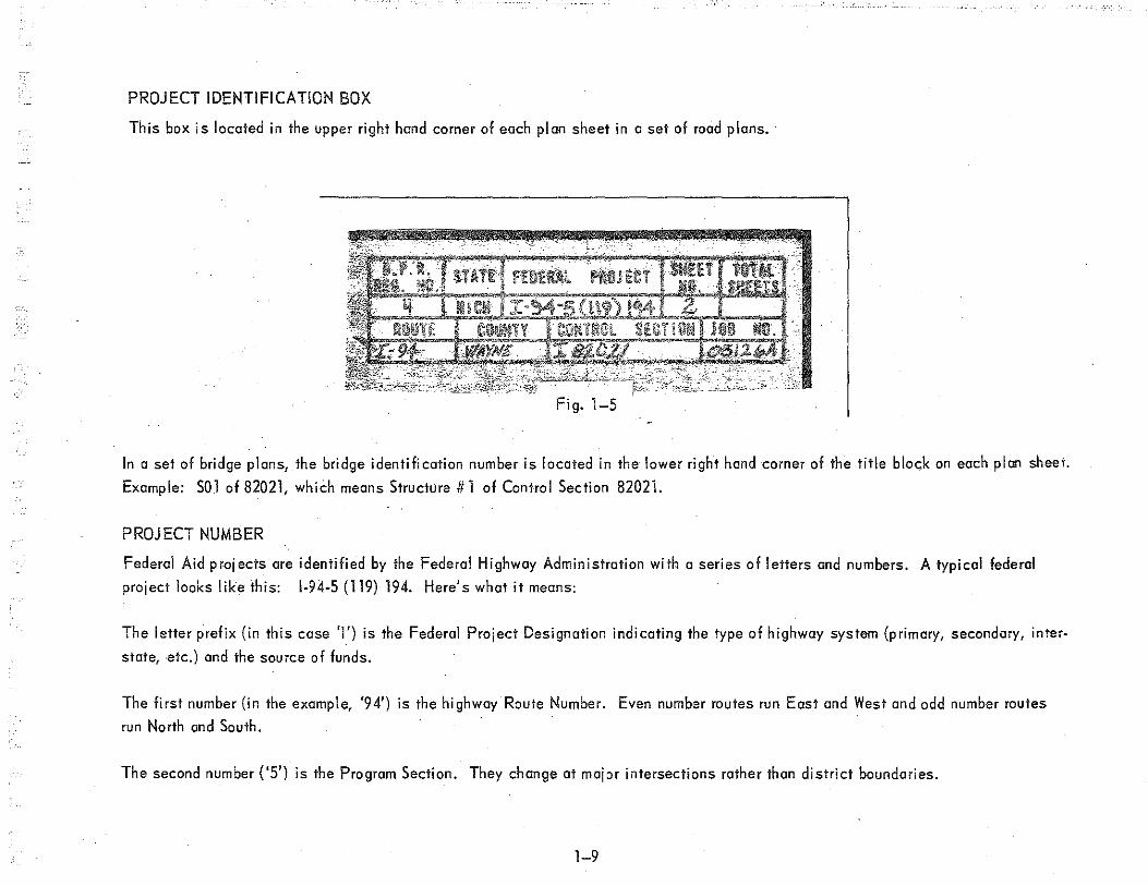
Stationing provides horizontal distance control. The centerline or reference line of a proposed project is drawn on the plan sheets.
Usually the survey centerline and the construction centerline are one and the same centerline, but they may also be diHerent center-
1 ines. The distances are shown as stations indicated with a "tick" mark on the line. Every fifth station is indicated with a short
line which crosses the centerline and the point is labeled with the station number.
Generally, the station numbers get larger as you go from left to right across the plan sheet and the plan view is oriented on the plan
sheet so that this left to right direction is from South to North or from West to East.
The centerline looks like this:
LINE BACK LINE AHEAD
13S
~~----+12~5---L __ ~I ____ ~I --~----+13_0 __ ~--~1 ____ 1~--~---r.---4-or like this:
Fig. 1-6
1-13
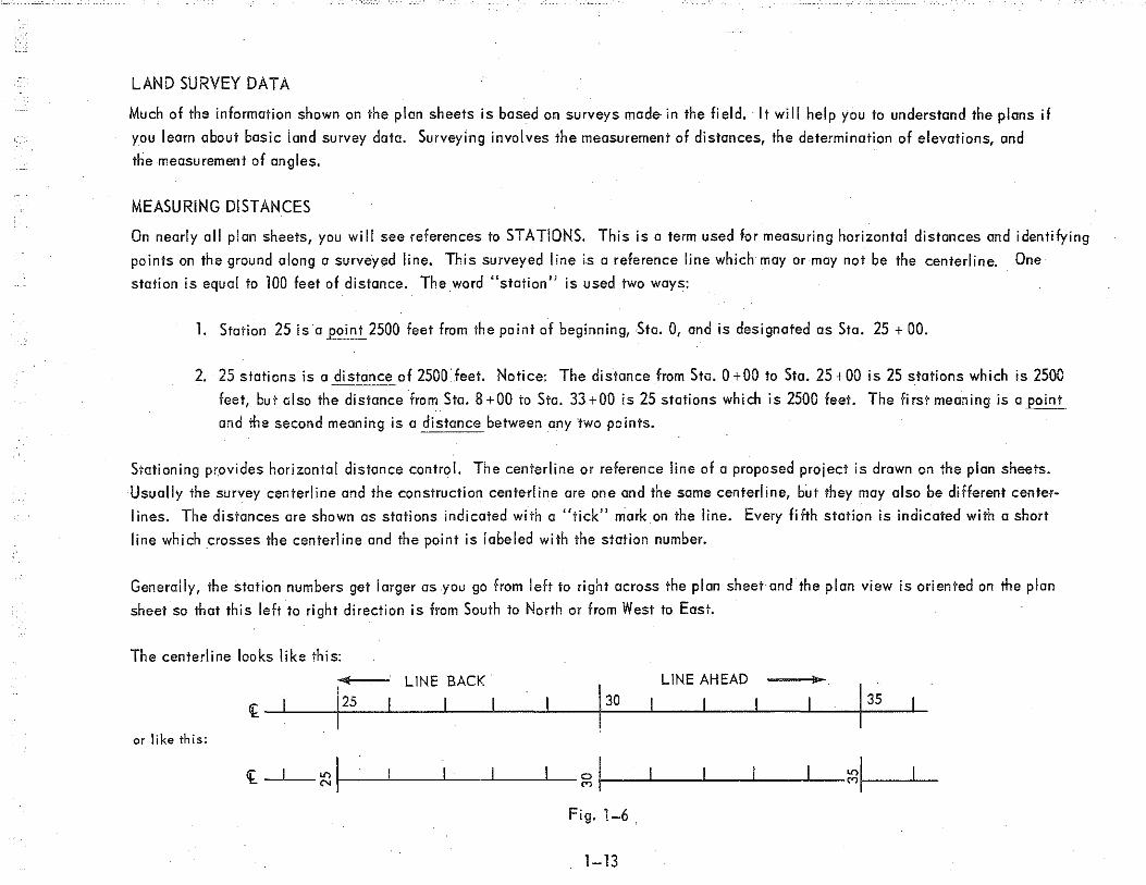
When a specific construction item is described in the plans, Hs exact location is defined by a station number. If the item is exactly on
a station point, you will see +'DO after the station point number. A point half-way between two station points would be shown with +50
after the lower station point number. The location of any point is always indicated as a plus distance beyond the last station point.
Example: 88 + 73.24 is the station number of a point which is 73.24 feet beyond station 88 and is 873.24 feet from the point of begin
~ing, which is station 80 + 00 in this example. To lind the distance between two points along a centerline, you subtract the lower
station number from the higher station number, ignoring the PLUS signs.
Example: Find the distance between Sta. 12+80 and Sto. 20 +60 in feet.
Distance
To find distance in stations, treat the plus portion as a decimoJI part of a full station.
Distance =
STATION EQUATIONS
20.6 12.8
7.8 Stas.
2060' (ignore plus signs)•
- 1280' = 780'
Station equations are used in centerline measurements when the stationing is not continuous throughout a project. This might occur
when a part of the project is resurveyed and the original alignment is changed. The result may be to either shorten or lengthen the
overall project. To avoid having to change all of the stationing ahead to the end of the project, a station equation is used. When you
see a station equation on the plans, it means the station numbering has changed. The point of the station equation really has two
station numbers. The first station number is correct when measuring BACK along the centerline and the second station number is
correct when measuring AHEAD along the centerline. Let's look at on example o£~ how a station equation affects measurements
and distances.
1-14

A station equation is shown on a plan sheet as follows:
Sta. 8 + 73.24 Back Sta. 10 + 56.86 Ahead
BENCH MARKS
Station Equation
Sta. 8 + 73.24 Back = Sta. 10 + 56.86 Ahead
Line Shortens 183.62'
Fig, 1-7
A Bench Mark (B.M.) is a point of known elevation, usually referenced to mean sea level. Many are located throughout Michigan which
have been carefully established by several governmental agencies. They provide vertical distance control. They are used during
highway construction to establish accurate elevations and ore generally located about every 1000 feet or less along the length of
the project.
Bench mark information is shown on the plan and profile sheets at the top of the plan view. The data is presented in this form:
B. M. # 132, Elev. 678.92 P.K. Nail, & MDSH& T B.M. Tag inN. root ol6"wild cherry
60' Lt of Sta. 1292+43
This means that Bench Mark Number 132 is at an elevation of 678.92 feet above mean sea level. It is marked by a Department standard
bench mark tag which is anchored by a P.K. nail in the root of a6 inch wild cherry tree on the north side of the tree. Looking up
station, ·the tree is located 60 feet to the left of the centerline at Station 1292+43.
1-15.

GRADES AND SLOPES
Since distances are measured vertically or horizontally, how is the rise or fall of the ground described on the plans? This information
is expressed either as a Grade or as a Slope.
A Grade is expressed as a Percent of vertical distance to horizontal distance. On the plans, percent grades are used to describe the
highway centerline, ditches, and sewer lines. A Plus(+) sign before the percent grade indicates a RISE in the ground going ahead
on line and a Minus(-) sign indicates a FALL. Thus the percent grade is the number of feet of rise or fall per station.
Example: A -2% grade means a fall of 2 feet per station. A simple formula for determining percent grade is:
% Grade = Vertical Distance
Horizontal Distance X 100
Example: What is the percent grade fo.r a li.ne whi.ch connects a point at Sta. 5 +00, Elev. 720.00 and a point at Sta. 8 +00, Elev. 711.00?
Sta. 8+00 800 Sta. 5+00 - 500
Horiz. Dist. = 300' Vert. Di st.
711.00
720.00
9.00
~ 9 00' · ( , f I ) % Grade = 300
X' 100 · = -3.00% 3 al per sta.
Remember these three ways of showing grades:
2. Falltng Grade 1. · Rising Grade
8+00 Elev.720.00 5+00
Elev. 711.00
T + 9'
'F-------1 _L
Elev. 711.00 ~-. • 3.oo~ -9'
0
T E lev. 702.00 5+00
r ...
3. Level Grade
300 ' _ __,..j
Fig. 8
Elev. 720.00 . ..,.., ___ o_.O_O_% ___ ., Elev. 720.00 8+00., 5+00
Fig. 1-8
1-16
300' -1 8+00

A Slope is expressed as a ratio between vertical and horizontal distance. When the plans show such things as crown of road, super
elevation, shoulder slopes, excavation slope and embankment slope, you will find them described as ratios rather than as percent grade.
Example: 1. Standard Crown of Road:
Given: 0.015' I ft. Means:
2. Superelevalions:
Given: 0.045' /It Means:
3. Shoulder Slope:
Given: Yl' '/ft. Means:
4. Excavation or Embankment Slope:
Given: 1 on 4 Means:
Fig. 1-9
Notice that when a slope ratio is given, the vertical distance is always given first, ,followed by the horizontal distance. Study the
Typical Cross Sections for slope ratios.~
1-17

U. S. PUBLIC LAND SURVEY GRID SYSTEM
Land survey grid systems are set up to identify land ownership and location of property lines. The grid system starts at an INITIAL
POINT, which is the origin of the grid. A true north-south line called the PRINCIPAL MERIDIAN and a true east-west line called
the BASE LINE are established which intersect at the initial point.
N PRINCIPAL MERIDIAN
INITIAL POINT
~BASE LINE
Fig. 1-10
In Michigan, the initial point is located at the midpoint of the southern boundary of Ingham 'County. The principal meridian for
Michigan is called the Michigan Meridian. Next, true northf-south lines called GUIDE MERIDIANS and true east-west lines called
STANDARD PARALLELS are established every 24 miles from the Principa I Meridian and Base Line respectively. The land is thus
subdivided into what are called 24 mile tracts. A 24 Mile Tract is an area approximately square 24 miles on each side. It is not a
true square because of convergence of meridians and curvature of a true east-west line. Many Michigan counties are 24 mile tracts.
1-18

2 d PARALLEL N. n
/ lstP ARALLEL N.
z 5 INITIAL Cl
"" /POINT UJ ::E
BASE LINE
z ~ 24 MILE TRACT
<>: <.!)
I .....- 1st P u ~2~~ ::E
ARALLEL S.
2nd P ARALLEL S.
-3 -3 UJ w wz wz wz Wz 9:o; Cl<O: Cl<>: 9:o;
Fig. 1-11 .. ii
The 24 mile tracts are then subdivided into 16 areas approximately 6 miles square. Each of these areas is called a TOWNSHIP. The
townships are numbered according to their position relative to the initial point. Example: T4N, R3E identifies the township which
is in the fourth tier of townships north of the baseline and in the third range of townships east of .the principal meridian.
1-19

i
1.:
;:o ;:o ;:o ;:o
z ...: Cl
"' UJ ::;:
_j
< "-u z
"' "-
;:o UJ
Fig. 1-12
1-20
UJ N
"'
I ~
6 Ml
UJ
v I
::E "'
/.....--
UJ .... "'
UJ
- T4N, R3E
TSN
T4N
T3N
T2N
TIN
BASE LINE
TIS
T2S
T3S
T4S
TSS

A township is subdivided into 36 areas approximately 1 mile square. Each of these areas is called a SECTION. The SECTIONS
are numbered as shown below.
6 5 4 3 2 1
7 8 9 10 11 12
) 18 17 16 15 14 13
</) w ...J
:::;:
"' 19 20 21 22 23 24
' 30 29 . 28 27 26 25
31 32 33 34 35 36
I~ 6 MILES
Fig. 1-13
1-21

Finally, a section is subdivided into smaller areas by quartering. The standard way of doing this is to divide the section into lour
Quarters, each Yz mile square,. and then divide each Quarter into four quarters each l4 mile square (a Quarter of a Quarter). Sectior. TO
is shown below.
SECTION NUMBERS
SECTION LINES
3 3 2
9 10 1 0 11
..---- NWlf.!---+--- NElf.!----.
NW% NE%
SW'4 SE%
10 11
SECTION CORNER
UJ ...J ::E
1/4 CORNER
1/8 CORNER
r--.--~---~~~~--~------l ~--~
QUARTER LINES
Fig. 1-14 I , '
15 14,
Notice that the Quarters are labeled according to their compass position within the section and the Quarter- Quarters according n
their compass position-within the Quarter.
1-22

Land"areas are usually measured in acres. A Standard Section contains 640 acres (1 square mile= 640 acres); a Quarter contains 160
acres(% X 640 = 160); and a Quarter-Quarter contains 40 acres(% X 160 = 40). These are approximate figures only due to irregularities
of actual sections.
Now let's put it all together in same example description of parcels of land.
Example 1: SW%, NW)>!, Sec. 10, T4N, R3E, Michigan Meridian, containing 40 acres, more or less.
Example 2: EY,, SW%, NE%, Sec. 10, 'T4N, R3E, Michigan Meridian, containing 20 acres, more or less.
I, Look at Example ·J ·again, this time read backwards through the description. First you get the approximate acreage of the parcel of land
(40 acres, more or less); second you read that the parcel of land is in Michigan (Michigan Meridian); third you get the Township within
Michigan (T4N, .R3E); fourth you get the Section within the Township (Sec. 10); fifth you get the Quarter within the Section (NW %), and
finally you get the Quarter within the Quarter (SW%). Written out more fully, the description reads: The SW% of the NW% of Sec. 10
of Township (T4N, R3E), etc.
Notice in Example 2 that the Quarter-Quarter is further subdivided by half (EY,). This area is indicated on the sketch oR Aext page.
1-23

4 3 3 2
9 10 10 11
SW% · NW% 40 Acres more or less
I
9 ~10------------------~~\r------~-----------10~ ~s 1sT 14
Fig. 1-15
Highway centerlines are referenced to section corners and% corners for control..
1-24
N.E. Cor. Sec. 10, T4N, R3E Michigan, Meridian
EY,, SW'4, NE'4, 20 Acres more or Less

['~1iCHlG_;::J~ DEP.t\RTN!ENT OF
A cross section of a highway project is a view of the project as if it were cut open by a vertical plane at right angles to the construc
tion centerline, looking ahead.· Based on their useful purpose, there are two types of cross sections used in highway work. They are:
l. Design Cross Sections
2. Typical Cross Sections
DESIGN CROSS SECTIONS
The main purpose of Design Cross Sections is for determining earthwork quantities. Design Crass Sections ore plotted to scale on
grid paper called "cross section paper." The divisions of the grid are the same vertically and horizontally. The profile of the
· existing grounCf' line is plotted first.· Then the rough grade line for the proposed roadbed, ·shoulders, ditches, and side slopes is
plotted. The area bounded by these lines is called "end area" and represents the cut or fill area of earthwork required, as illustrated
in the sketches below. ·
Sta 10+00 Proposed Grade
CUT AREA-EXCAVATION
Slope Stake Point (Typ.)
Fig. 2-1
2-1
Proposed Grade
Sta 20 + 00
FILL AREA-EMBANKMENT

Cross sections for many station points along the construction centerline are plotted on one design cross section sheet, ·and there are
usually several sheets required for the entire length of the project.
The volume of earthwork between two adjacent station points is computed by averaging the two end areas andmultiplying by the
distance between the station points. (See the sketch below)
Existing Ground
End Area Sta 6 + 00 (Fill)
VOLUME OF FILL
Fig. 2-2
Proposed Grade
End Areo, Sta 5 + 00 (Fill)
Slope Stake Line
The total volume of earthwork for a project is determined by combining the results for all the pairs of station points involved. These
earthwork computations ore programmed on the Department computer.
Design Cross Section Sheets are not included in the contract plans, however, they will be furnished by the Design Office upon the
request of the Project Engineer. Grade and volume sheets are also available.
2-2
TYPICAL CROSS SECTIONS
The main purpose of Typical Cross Sections is to show all the construction details and dimensions necessary for the grading and
paving operations.· Sometimes several different typical cross sections are needed for a project. The beginning and ending station
points or other identification points mark its limits. Every different type of cross section must be shown so that the engineers and
contractors will have sufficient plans and details with which to work.
There are two basic types of Typical Cross Sections based on whether the section is on a straight line or on a horizontal curve,
They ore:
1. Normal Section -on a straight line (called tangent)
2. Superelevated Section- on a horizontal curve.
The pavements on most horizontal curves are superelevated to give better traction lor the cars going around the curve at
high speeds. The outside edge· of the pavement is elevated so that the pavement surface slopes down toward the inside
of the curve. ·
The transition from normal crown to full superelevation is accomplished gradually. Superelevation builds up gradually at
the beginning of thecurve and is taken down gradually at the ending of the curve.
2-3

.._I I
§I •-..1
Cont. Reinf. Cone. Pav' t. 9" Unif.
Plan Grade
36' CONCRETE ROADWAY Normal-Section i
Fig. 2-3
\.;' '0
\'::> \/
~~m~;----------~«,~>m~~~wm%~~,~
Ex. Ground)

36' coNCRETE ROADWAY Superelevated Section
fig. 2-4
2-5
Plan Grade
~ Ex. Ground

Listed below are the major items on the Typical Cross Section shown:
A. Pavement widths
B. Shoulder widths
C. Base width
D. Subbase width
E. Ditch width and depth
F. Crown of road slope for nonmal sections (Standard at 0.015'/ft)
G. Shoulder slopes
H. Front slopes
I. Back slopes
J .. Subgrade Slope rate,
K. Pavement thickness
L. Shoulder thickness
M. Base thickness
N. Subbase thickness
P. Plan grade (0.00) Q. Cut or fill distances frdm plan grade to key points.·
R. Notes
S. Type of pavement joint
T.: Guardrail

TYPICAL CROSS-SECTION
@ @ @
@
I © @ ® (f) r"'/ Class A. Sltldrs.
~ C~mc. Pavlt. Guard Rail, as
~ ~ called for on Plans.
1\ "'' -~ ® =
Plan Grade ® ~@ (f"..,../ Point of Rotation +0.18\ 0.00 @. 0.00\ @ <!_ I I
CD Pla~~de ~I
3A"!Ft. 1l ~-\- llriginal
'/// . ;·::;;::.~ .. ~:.: ' >'::,:: . (Typ,)_ -1f£, '"clr ' o\\ ~ / ., s;ohe •• \ --................... ® - ® /
"'-.... Subbau 0.02'/Ft. - -Ground '- .... lonsaras Base for Cone. ' I. .I ® ' I ~ha•n 0
@ ~ -- -·· !LP/a!Js ~
Width © ® @ '--------- Round Bottom Ditch;
Width, Depth & Backs lope as called fnr on Plans. @
Fig. 2-5
2-7

12.11'
7. 72'
a .47' 5'
2'
Beam Guard Rail, as cal led for on Plans.------__
-2.65
(Slop~ to
TYPICAL CROSS-SECTIONS 12'
11' 12' ,, r
/-0.18
-1.31_.t-- D.D2'/ft.
"' 12'
Cont. Re inf. Cone. Pav 1 t. 9" Unif.
ID"
-1.14!) Subbase In Place
12'
o. 02 • r .
Limits of Topsoil Excavation
Guard Rail, as called for on Plans.
(Typical,----
Fig. 2-6
Fig. 2-7
2-9
··•.·.·.
10' ,,
'- 1 "
12. oo• 7. 60'
1. Freeway cross section
70' Inside EdJ to Inside Edge
til t
Depth as cal led for on Plans.
12. 00•
7. 611'
_, ~-0 . ., I o "· ~II _
2 33 Pla!!._~I_!de
2 JJ - · \ ~
10• ,,
~ /
-2.42 -.--,~ \-.;; ....._ O(J 6 -2.42, \ "'-.I ::;-\ ....... ....._ '"- \ _..1 _... I_,...-- -1.13
~ 0 ~ vc 0 -~Ft. 0.02'/Ft. vc ~~.; ?'Nf '\~"><&~~~~-
DUAL 36' CONCRETE ROADWAY
NORMAL SECTION
2. Rural two lane road cross section
Cone. Pav 1t. 9" Unif. (Reinf.)
Plan Grade
12• "' Cont. R&inf Cone. Pav' t. 9" Unif.
/
I an Grade 0.00 (ijj) /tD.18 (ib)
\1/ o.oo, T ,.,,;;;;:;(.-!:'.i·
D. 02 1 10"
( ' -1.14
'-Subbase in Place
,,
Polnt of Rotation 0. 00
tO.! 0 o.oo
Subbase
Agg. Base lor Cone. Est. 4" (3" !lin. after final Shaping.)
-1.75
12' 12.11'
12' 11' 7.72 1 ,, 3.47' ,,
\ S V4"(Typ.) -2 61/ / .... '...._0 VC c YG
"-... ~ll:i Base for ClinG. _2 63 · o~'. 'fl....1 YC" d £st 4" (3" Mtn. _;z:::: after final ShapinJ.)
Ex Ground ltdth
Round Bottom Ditch: Width, Depth & BackslOPD, as called fnr an Plans.
Round Bottom Ditch; llidtb, Depth & Backs lope as called for on Plans.
., '-Ex. Ground

4' 6"
2' 2' - 6" Typ, (Typ.}
(Typ. l \ l" Ft. -
~Cone. Curb & Gutter !letail 02 (Typical)
ar 1ab le 12'
-o.otslfl. ' ' '
0.02 'F't:-
.'>. 10 Svb64.re
Fig. 2-8
3. Curb and gutter cross section
12'
Cone. Pav't.
/
S" Un'f. (Reiof.)
I (ib) I / PI'" '"'' \1/ 0.00
~ .: ·. (j.·: 4 ..
1 0"
-1.92 \ '-Subbase
12
' -· 0.0.2' Ff
Look again at She.ets No. 3 thru 6 and study them in greater detai I this time.
2-11
12'
~·~ AQg. Bose for Cone. ~ Est 4"(3"Min. After Fino\ Shoplnq}
Variable
0.02' Ft.
4' - 8"
: '·d: :.
I oil 2

• • .. • II
• • • • • • • • II
In Chapter 1 you were introduced to some basic information about measuring horizontal distance and elevations, the meaning of stations
and station equations, grades and slopes, and the way land is divided by"survey grid lines. All of these items ore imp<>rtant to defining
Highway Alignment.
The contract plans sh()wn are two views of the alignment: 1
1. Horizontal Alignment is shown in the Plan View .
2: Vertical Alignment is shown in the Profile View.
These views are shown one above the other on the Plan and Profile Sheets or on separate sheets with the plan sheet preceeding the,
orofil e sheet .
HORIZONTAL ALIGNMENT
The horizontal alignmentof a proposed highway is shown in the plan view of the Plan and Profile sheets. The location of buildings,
utility poles, underground utilities, fences, trees, other topography, property lines, R.O.W. lines, and survey grid lines in relationship
to the centerline alignment are also shown. A construction centerline consists of a series of straight li.ne segments called tangents,
connected by horizontal curves where changes in direction occur .
3-1

HORIZONTAL CONTROL POINTS
Horizontal control is maintained by means of control points spaced along a construction centerline. They are:
1. Point of Beginning (P.O.B.)
2. ·Point on Tan gent (P .0. T.)
3. Point of Curvature (P.C.)
4. Point of Intersection (P.I.)
5. ·Point of Tangency (P. T.)
6. Point of Ending (P.O.E.)
7. Ties to Section Corners and~ Corners.
Examples of these six points are indicated on the sketch below:
Tangent
P.l:-)
( Horizontal Curve
Fig. 3-1
3-2
/''·
Tangent/
I P.O.E.

The P.O. B. and P.O.E. mark the two ends of the project and are shown on the contract plans as follows:
Const. <[
Michigan Project 1-94-5(119) 194 Control Section 1-82021-05126A
Begins Sta. 1218 + 53.21 Freeway
Fig. 3-2
Michigan Project 1-94-5(119)194 Control Section 1-82021-05126A
Ends Sta. 1310 + 00 Freeway
Const. <[~ S
_ _,_ __ _._.:.___,__ M +---'-
P.O.T.'s are located at convenient points along tangents (straight lines) of the centerline and are used for establishing line for con
struction staking.
Changes in the direction of the centerline alignment result in a series of intersecting tangent lines. The P.l.'s mark these intersections.
The end points of the curves between the intersecting tangents are the P.C.'s and P.T.'s. The P.C. is the beginning point of the curve
and the P. T. is the ending point of the curve looking ahead on center! in e.
These contra I points should be carefully witnessed so they may be easily relocated si nee they are obliterated many times during
construction. The information about witness points is placed in note form on the plan view.
3-3

DIRECTIONS AND DISTANCES
A North arrow is shown on the plan view to orient the job and indicate general direction. Specific directions along the centerline
tangents, looking ahead on line, are indicated by means of bearings. The bearing of a line is indicated by the quadrant of the compass
in which the line falls and the acute angle (less than 90°) measured from North or South. The four compass quadrants are NE, SE. SW,
and NW. Examples are. shown on the sketch below. 1
N
A
LINE BEARING
OA N 32° 30' E
OB S 81"00' E
oc S55"30'W
OD N 44.00' W
c
s
BEARINGS Fig. 3-3
3-4

~:- - ;.
BEARINGS
To go in the opposite direction along a line, the reverse bearing is used. The reverse bearing is determined by changing the compass
quadrant of the bearing of the line to the opposite quadrant. For example, the reverse bearings of the lines shown above are listed below:
LINE REVERSE BEARING
OA s 32" 30' w OB N 81" 00' E oc N sso 30' E
OD S 44° 00' E
A change in direction at a P.l. is indicated by a deflection angle which is identified by the symbol A which is the Greek letter "delta."
The forward tangent deflects either to the left (L) or to the right (R) from the extension of the back tangent as shown in the sketch below.
Back Tangent A= 20" -00' L
Back Tangent
P.l. P.l.
Fig. 3-4 /
Usually the deflection angles ore not indicated directly on the centerline alignment, but are given in the horizontal
curve data as shown here.
b.= 3°- 10'- 49" Lt. D = Oo - 12' (Arc)
R = 28,647.89'
Construction q_ Curve Data
T = 795.27 E = 11.04 L = 1590.14
3-5
P.C. 1218 + 53.31. P.l. 1226 + 47.58 P.T. 1234 + 42.45

Distances along the centerline or reference line are measured by means of stationing. The station points are indicated by "tick" marks
spaced 100 feet apart and usually only every fifth station point is labeled. The location of any point or object on the plan view is
identified by two distances. The first is the distance out at right angles from a centerline station point to the point or object which is
either left or right of centerline looking ahead on line and the second distance is the station of the centerline station point.
Examples are shown in the sketch below.
12" Elm
''•'"''~ 72' Lt.
0 90' 0
0 0
+ +
"'
~ Sta. 27 + 85
0
N '"' 90'
36" Oak 68' Rt.
Fig. 3-5
HORIZONTAL CURVES
The intersecting tangents of the centerline are connected together by horizontal curves to permit cars to change direction gradually
instead of abrupt changes at the P.l.'s if curves were not used. If the road is for high speed traffic, •the curve must be "flat" and
extend a considerable distance each side ol the P.l. For low design speeds, the curves may be "sharper" and extend shorter distances.
The horizontal curves are arcs of circles. The straight line portions of the centerlines are tangent to these circular curves. That is
why they are called tangents. The Degree of Curve (D) of a circular curve is the angle at the center of the circle with Radius (R)
subtended by an arc 100 feet long (one station). It identifies how "sharp" the curve is and may be used to compute the radius.
D/2 is what is turned every 100 ft.
3-6

100'
D =· 6'
uFiatn Curve
(Long Radius)
D = 30'
''Sharp'' Curve (Short Radius)
Fig. 3-6
uTcngent"
The symbols used to identify the different ports of a horizontal curve are listed below and labeled on the sketch. Horizontal curve
information is given on the plan view. If the curve is superelevated, ·the rate of super is specified at the bottom of the curve data.
!::. = Deflection Angle E = External Distance
D = Degree of Curve M =Middle Ordinate Distance
R = Length of Radius of Curve P.C. =Point of Curvature
T = Length of Tangent of Curve P.l. =Point of Intersection
L = Length of Curve P.T. =Point of Tangency
L.C. = Length of Long Chord
3-7

--<""··-
L
M
[----' L.C.
I
l-Tangent Line
R R
Fig. 3-7
3-8
' .)

VERTICAL ALIGNMENT
The vertical alignment of a proposed highway is the relationship of roadway elevations along the length of the project. Vertical align
ment is shown in the profile view of the Plan and Profile sheets.
Vertical control is maintained by the use of a series of bench marks conveniently located along the project. Bench mark infOrmation
is given in note form on the plan view of the Plan and Profile sheets. (Example BM#12 Erv. 802.83)
THE PROFILE
Profile is a general term referring to both the existing ground line and the proposed grade line called plan grade. Points on a profile
are located in the horizontal direction by stations and in the vertical direction by elevations. Existing ground elevations to the
nearest 0.1 foot are used for plotting the existing ground line and the propos!ld grade elevations to the nearest 0.01 foot are used for
plotting the proposed grade lines. They are plotted on a profile grid which consists of vertical lines which mark off reference stations
usually to a scale of 1" = 100'. The vertical scale is different in order to give a distorted view of changes in elevations for ease in
interpreting the profiles. The reference stations and elevations are labeled along the bottom edge and. left edge of the grid respectively.
The existing ground line is usually an irregular line representing the profile view of the natural ground. It is plotted on the grid by con
necting the existing ground elevation points with o series of straight lines (drawn light). The proposed grade line represents the
profile view of the proposed roadway and is plotted on the grid as a series of straight grade lines (drawn dark) which intersect at points
where the proposed grade (in percent) changes. Vertical curves are used to connect these intersecting grade lines. The existing
ground elevations and proposed plan grade elevations at the reference station points are printed along the bottom of the grid. The
sketch Fig. 3-8 illustrates the basic elements of the profile view.
3-9

850
840
830
r 820
~ ~ -o u 6 c ·- .,.; ~ ~ M ~ 0 co ~ > - ~ ~-n::w
.
. ...,. .... 0 M co
9
Reference
Station =
/ Existing Grade Line
v
~ (CUT)
+ 0.50%
~ (FILL)
" -1/ Existing Ground Elevation
I ~Proposed Plan Grode Elevation
1 ,, " M
...,. ~
...,. "' "' ~ ....
;>i '"1 ": r..: "' o:i ": ~ M M N "' co M co M co co M
co co co co
.360 I 2 .3
PROFILE
Fig. 3-8
3-10
I
/ Propose~ Grode Line
I -------/
"' ...,. N .... ,...; N
co M co
4
----- (C\Ji) /
/__
0 .... .... -o M M co M
co
.365
' Prep. Fl. El.
0 830.00 (15")
L Cul~ert
""! ~ ..... ~ M co co
6
Scale: Horizontal
Vertical
I
" ...,. N .... 0: ..; <'"> M co "'
7
1" = 100'
1" = 10'

Other general information such as quantities and the respective details called for, ore indicated on the profile sheet for such items as
sod, guardrai I and earthwork.
Other profiles may also be shown, •such as proposed ditches. Existing ground elevations at points left and right of centerline ore
sometimes plotted as short dashes(·) and are not connected to form a profile line. In the case of a divided highway, o separate set
of reference elevations is used for showing the profile lines for the median, for left of centerline and for right of centerline. The
various profile lines are described in legend form to the left of each set of reference elevations.
DITCH AND SUPERELEVATION DATA
A dependent ditch follows the some percent of grade {is dependent on) as the proposed roadway. An independent ditch follows a
grade of its own which is different (is independent of) from that of the proposed roadway. The percent grade for an independent ditch
is silown on the ditch profile.
Along the lop of the profile view are horizontal lines on which information about the proposed ditches and superelevations are given.
The ditch in.formotion consists of the width and depth of the ditch, the backslope, and the fronts lope. The superelevation information
consists of the stationing of the I imits of Super T ronsition and Full Super.
Example: 1 on 6 B.S. Lt. 1 on 6 F .S.
Depth from f < 4' X 6' R.B. Ditch
Plan Grade· _id_t_h_.~-lai-------4_'_M_e_d_ia_n_D_it_c_h ____________ -:------
1 ... 0 N
+ rL")
4.5'X 6' R.B. Ditch
180' Super Trans.
0 0
+ Oo
"'
1 on 6 B.S. Rt.
0.04'/ft. Full Super
Rotate about Rt. EPM.
Fig. 3-9
3-11
0 00
+ 0
"'
1 on 6 FS
180' Super Trans. ...I 0
"' + N
"'

VERTICAL CURVES (V.C.)
The intersecting grade lines are connected together by vertical curves to permit cars to change grade gradually. The vertical curves are
segments of a curve called a Parabola and are called Parabolic curves. The sketch below shows a vertical curve and how the in forma·
tion is presented on the profile view.:
Point of Vertical Intersection
Point of Vertical Curvature "'
(P.V.I.) Sta. 1225 + 00
(P.V.C.) Sta. 1219 + 00. "'! 0 Elev. 703.65 C") 0
R +
/ ' Point of Vertical Tangent
\ (P.V.T.)
J + Q.90o/o ,__ r-- Sta. 1231 + 00 --~ I I 700 --I_ - - r-_
- 1(4% ~ 1200'V.C. 0 I-695 0 > ~ -
690 w
.
.
685
9 1220 2 3 4 1225 6 7 8 9 1230 2 3
Station
Fig. 3-10
When a roadway goes over a hill, it reaches a high point, or summit point, and when it goes down through a valley, it reaches a low
point, or sag point. The sketch below illustrates these ideas.
Fig. 3-11 /
3-12
r-
4

Certain things need to be done before roadway construction is started. Obstruc;:tions which unnecessarily interfere with construction
must be removed from the right-of-way. Obstructions may include utilities, buildings, ,trees, and brush. They are removed in preparation
lor construction.
Depending upon arrangements made for a specific project, certain obstructions may be removed under separate contracts.
Most requirements for removing obstructions are set forth in the Standard Specifications. However, special information and instructions
for a specific project may appear in the Proposal, and/or on the Removal Sheets, and/or as notes on the Note Sheets.
REMOVAL AND/OR ADJUSTMENT OF UTILITIES
Certain public utilities, ,such as power lines, telephone lines, ,water lines, 'sewer lines, and gas lines, must be removed from the project
right of way and/or adjusted within the right of way so as not to interfere with roadway construction., For example, ,water lines may be
lowered so as to pass safely below the roadway subgrade.

Utilities are shown with symbols on the plan view of the Plan and Profile Sheets and on Removal sheets. Some standard symbols for
utilities are listed below:
36" Sewer MH MH Sewer -====0,===0
M.H. Valve Hyd. Cap. Meter
Water Line ___ --0-- _ --¢--- ---(D
M.H., Valve Gas Line ---0:-----
Telephone Cable -- -- ---
M.H.
M.H.
--9---
PowerCable -------@------
Fig. 4-1
24" Storm M.H. 12" Storm C.B. .- - - - - -o- - --- -t:::l. ------ -------
Telephone Pole
Power Pole
' Guy Pole
The utilities are usually removed and/or adjusted by each utility company's own work force. Sometimes they may be removed, adjusted,·
or replaced as part of the construction contract.
4-2

REMOVAL OF BUILDINGS
Buildings and other man-made objects must either be demolished or removed from the project right-of-way before construction begins.
Also, ,fences must be removed. These are shown on the Removal sheets with symbols. The symbol used for buildings is the actual
plan shape of the building with a brief description of the type of construction.: Examples:
B 3 Story
Brick Apartment - 1 Story Frame No Basement - House # 2784
# 1327 1 St
'• I
Fr. Gar.
Fig. 4-2
Buildings and other objects to be removed are indicated by cross hatching and/or with a note as shown below:
1 St. Blk.
Gas Sta. ·
# 8630
Remove
Building
Fig. 4-3
A note is shown for buildings within the right-of-way which are to be demolished.
4-3
J
Remove
Signs

CLEARING
Clearing is the process of cutting, removing from the ground and disposing of trees, ,brush, shrubs, ,and other obstructing vegetation
from the construction site. The clearing operation involves the removal of all vegetation occuring within the right of way which
interfere with excavation, embankment or clear vision area. ,
Trees are shown on the Removal sheets by symbols with the sizes noted. The size is the diameter 4)'2 feet above the base of the tree
at the ground line.
Examples:
Fig. 4-4
A symbol which is the actual shape of the general area covered by brush or other vegetation with a "clear & grub" note is shown on
the Removal sheets.
REMOVAL OF PAVEMENT AND SIDEWALK
Existing pavement and sidewalk which is to be removed is shown on the Removal sheets as follows:
Remove old pavement ~ Remove old sidewalk ' ~
Fig. 4-5
4-4

CONSTRUCTION SIGNS
The final preparation for construction is the placement of required construction signs. The contractor is required to provide necessary
barricades, ·danger signals, signs, and other traffic control devices to insure the safety of the motoring public and to properly control
and direct traffic.· Temporary signs used while construction is in progress can usually be found on the sta,ging sheets.
No one standard sequence of signs or other control devices can be set up for all situations, but there is a high need for uniform
standards. Therefore, ·the "Michigan Manual of Uniform Traffic Devices" sets forth the basic principles and prescribes standards
lor the design, application, and installation of the various types of traffic control devices required for road construction. As part
of these standards a number of typical situations are illustrated as shown.
4-5

500'
W20-1
" 40~E LAN~~, ROAD 1250'
,AHEAD~ "¥{'
W20-4
Suggested application of traffic control devices on a two·lane highway where one lane is closed at a
spot location.
Fig. 4-6
0
0
0
0
0
0
0
0
0
0
0
0
• 0 t n
KEY 000 Drums or
Type II Borrice~des
=Type ill Barricade
W20-l
ONE LANE ROAD .eY AHEAD ·
NOTE:
L" Minimum length of taper S "Numerl~al value of speed limit
W " Width of offset
KEY
ODD Drums
+a Floshing Arrow Panel
Suggested application of traffic control devices where construction or
maintenance activities
occupy one lane of a anew
way roadway.
Fig. 4-7
0
0
0
0
0
0
CONSTRUCTION ZONE ENDS
Although each situation must be dealt with individually,· conformity with the provisions established in the manual is required. All traffic·
control devices used on highway construction shall conform to the applicable specification of the manual.
4-6
Once all utilities, buildings and other structures hove. been removed from within the construction limits and clearing operations have
been completed, the contractor may proceed with the grading. The contractor works from lines and grades staked by MDOT construc
tion survey crews under the supervision of the project engineer.
EXCAVATION AND EMBANKMENT
The most important element of the grading operation is construction of the roadbed. The roadbed is constructed by excavation through
cut sections and by construction of the embankment through fill sections. The slope stakelines, shown as dashed line in the plan view,
are the limits of roadway width. These lines are where the constructed roadway slopes and original ground intersect. (See slope stoke
lines shown on Fig. 5-1)
5-1

SLOPE STAKE LINES
co co
u-<> 0...~
------- ---~~ ----------S. Frontage Rd. 755
Fig. 5-1
i-"~-i: / :f.: ·<:-e//
'-'' _, C:,\0\<.~ •• /
c:,\ol'':,- _,-----
/ /
/<%-• . /p
/ x"· " / "'
/ /
In cut sections, the proposed grade line is lower in elevation than the original ground line. The original ground must be excavated
(cut) to the planned elevations. The amount of cut is found by subtracting the elevations given at the bottom of the profile grid:
Original Ground Elevation
Plan Grade
Cut
679.4 675.90
3.5 ft.
In fill sections, the proposed grade line is higher in elevation than the original ground line. Earth materials are placed in an embank·
ment (fill) above the original ground to the planned elevations. Topsoil is removed from the original ground before the fill is placed.
The amount of fill is found by subtracting the elevations given at the bottom of the profile grid:
Plan Grade 677.80
Original Ground Elevation - 67 4.0
Fill 3.8 ft.
5-2
. --,:

Slope Stake
Slope Stake
Original Ground
Cut Area
"': ~Plan Grade "' o.n ,..... ,..._ "' "' .
CUT SECTION Fig. 5-2
PI an Grade
FILL SECTION Fig. 5-3
5-3
Original Ground Slope Stake
:rypical Section Template
Slope Stake
48909.

Remember that a profile is like a longitudinal cross-section of the road, that is, a cross-section taken along the length of the highway
rather than from side to side. And the proposed grade line represents the proposed elevations along the center line or reference line
of the roadway. The original ground line shows the existing land before construction begins.
The proposed grade line is usually shown by a heavy dark line and is regular and smooth. The original ground line is usually a lighter
line and is very irregular as the original ground is before construction begins.
PC
Original Ground Line ) \ Cut
\ Proposed Grade Line
PT PROFILE
Fig. 5-4
CONTRACT DATA
Contract data is given on the title sheet in addition to the Contract Proposal. The contract length is indicated by the station of the
P.O.B. and P.O.E. The specifications governing the project are identified in a note directly under the project identification box. The
project work items covered by the contract ore given at the top of the Title Block.
Example:
Contract for: G. & D.S. Dual 36' - Cont. Reinf. Cone. Pav't. 24'
Cone. Pavt. 16'Conc. Ramp & Vari. Width Cane. X Rd.,
Util. Alter., Bridges.
5-4

----. ·-. ~--- -.
Exp lonotion: "G. & D.S." means grading and drainage structure work. "Dual 36' Cont. :Reinf. Cone. Pav't" means a divided highway with
two 36' wide pavements constructed with continuously reinforced concrete. Also, there are 24' wide concrete pavements and 16' wide
concrete ramps to be constructed.· "Vari. Width Cone. X Rd." means there are cross roods to be constructed which have variable width
concrete pavements. "Uti I. Alter." means alterations are to be made to utilities. "Bridges" means that there is one or more bridge
to be constructed.
The major items of work listed above are:
]. Grading -covered in this chapter.
2. Drainage - covered in Chapter 6.
3. Paving - covered in Chapter 7.. 4. Bridges - covered in Chapter 8.
Special information and quantities of work to be performed for grading operations are shown on the quantity sheets and on the profile sheets.
DESIGN CROSS SECTION
Design cross sections are plotted on cross section grid sheets and show the grading section superimposed on the original ground section
at different stations along the construction centerline. The quantity of earthwork on a project is computed by the Design Division using
the information shown on the design cross sections. The design cross sections are not included in a set of construction plans. However,
they are.available upon the request of the project engineer.
Design cross sections serve to establish limits of grading in the field. These limits ore stations, elevations, ·widths, and slopes. Values
of these limits are shown on the design cross sections, .and on the typical cross sections. ,
5-5

Existing North Service Rd
'1+11 Htll J 't '
.,. ' - ' -' ' '
6 80.0 '
- l . . ' ' ' -I
I . " ~
/ . '
• - - t 0-:> .,
70.0 + ' ,.;>• - ~
' '1 ,. 6
J I t
' ' "' . ""' I\,~ t - ' t
' I t
- ' ' I . ' I
- ' .
6 60.0 IHH- H:
0-lo" ~
Cl
1 Existing West Bound
'
100+00 CUT = 5420.0 FILL=lO.O.
DESIGN CROSS SECTION
Fig. 5-5
5-6
/
'
0-lo' ~
"' ""' ~
Proposed Freeway Sect 1 on
Existing East Bound
...
\ 0~ b
..
'V cS
'

On a design cross section sheet, one can estimate:
+ CUTS AND FILLS by noting relative positions of proposed grade and original ground.
+ SLOPE RATIOS by counting grid sql.!ares horizontally and vertically.
+ SLOPE STAKE DISTANCES by counting grid squares horizontally, ·left or right of centerline.
+ SLOPE STAKE ELEVATIONS.by counting grid squares vertically above or belowthe reference elevation line.
+ DITCH WIDTHS by counting grid squares horizontally.
+ DITCH ELEVATIONS by counting grid squares vertically, -above or below the reference elevation line.
+ ALIGNMENT of proposed roadway to the existing roadway.
SOIL DATA
The contractor and the construction inspector must be aware of tfte kinds of soils that will be encountered during grading operations.
Soi I surveys are made by the Soils Division of the MDSH& T to obtain soi I data to include in the pi ens. Soil data is shown on the plan
and profile sheets.
The soil series is indicated in the plan view as follows:
oOG 0 0 0 80 0 eO 0 Ill eOOO e 0 •:• •:•:o• ••.• • ••• • • • •• • • • • 0 • •• • ••
: .. · : .. : ·. : ·. : : ... : ·: : •
• 0, •". • • • •• • • •••••••
GJ e • o ••e o • o o • o o o e 0 0 o a o • o Ill • o 0 8 •• ,.• o :·. o 0 .,o•o 0 00 0 0 G .• o o 0 o o o • o o e e o 0
5-7

The soil profile is shown in the profile view as a log of boring obtained at a certain test hole. Example:
T.H. No. 18 Sta. ·1225 + DO
45' Rt. of Constr. Cl
W.T. @ 4.5'
HWT.@ 4.5'
0-11' Medium to Fine Yellow Sand
·:. ·. Sample 4 - 10 (passes Class II)
11' to 12.5' .Firm Gray Clay
Fig. S-6
5-8

EARTH GRADE
The earth grade is the completely graded roadway before placing the pavement structure., The" earth grade width extends to the outside
edge of the ditches, or the toe of fill slopes, or a specified distance back of the curbs. The subgrade is the portion of the earth grade
upon which the pavement structure is constructed. The construction of the pavement structure, which consists of the subbase, base
course, shoulders, or curbs and gutters, and the surface courses, 'is covered in Chapter 7. Standard Rood Section nomenclature is '"·
dicated on the drawing shown below:
RIGH
EMBANKMENT SECTION
EARTH GRADE
ROAD SECTION NOMENCLATURE
Fig. 5-7
5-9
CLAY
SHLDR. PT.
(TYPICAL)

The work of constructing the earth grade is called roadway earthwork. This work shall consist of constructing earth grades by excavat
ing soil or rock, and by placing embankments. This work shall include salvaging and stockpiling of selected material, disposing of
surplus or unsuitable material, trimming the earth grade, and maintaining the work in a finished condition until acceptance.
Roadway earthwork may be classified as rock excavation, ,earth excavation, subgrade undercutting, peat excavation, swamp backfill,
intercepting ditch, machine grading, trenching, or embankment (CIP). CIP is the abbreviation for compacted-in-place. All work to
excavate materials, except rock excavation and subgrade undercutting, which is not covered by separate items in the contract, will be
classified as earth excavation.
Prior to acceptance of the earth grade, the Soils Division personnel make tests of samples of the soil to determine if subgrade under
cutting is required to remove unsuitable soil from the roadbed. Sand backfill is used to replace such unsuitable soil.
DETERMINATION OF CLAY SHOULDER
Let's now go through !he steps involved in the determination of a clay shoulder point location. We will use the right clay shoulder
point for Fig. 2-6 (Pg 2-9), and station 1220 +50, (Fig. 6-6) for an example.
Clay Grade
Typ. 'Clay Shoulder Point
Fig. 5-8
5-10
Right Clay
Shoulder Point

Steps 1 through 6- Determine Plan Grade and Front Slope using the plan and profile sheets.
Step 1: The nearest P. V.L (point of vertical intersection) is at Sta. 1227 + 00, Elev. 669.65.
Step 2: The horizontal distance from the station to the P.V.I. is
1227.00- 1220.50 = 6.50 stations= 650ft.
Step 3: The percent grade, is 0.90 %.
Step 4: The difference in elevation between Sta. 1220 +50 and the P.V.I. is 6.5 Sta. X 0.90 ft/sta = 5.85 ft.
Step 5: Therefore the plan grade at Sta. 1220 +50 is 669.65 - 5.85 663.80
Step 6: Next determine the E. Bd. front slope which is found on the bottom horizontal ditch information line at the top of
the profile sheet. In this case a 1 on 6 F.S.
Before continuing we must determine which typical cross section applies to the location and roadway we are working with. In this case,
it is the Normal Typical Section Fig 2-6 which applies for Sta. 1220+50.
Steps 7 through 13- Determine Clay Shoulder Point Location and Elevation, using the typical cross section in the contract pions.
Step 7: Determine the location of the Plan Grade Point with respect to construction centerline In this case, it is 35' right of
centerline and is the left edge of pavement.
Step 8: Determine the horizontal and vertical location of the pavement crown point. Here the horizontal distance is 12' right of
Plan Grade Point (P.G.P.). For the vertical distance we make use of the Stondard,Siope Rote which is 0.015' ft. Therefore 0.015' I It X 12' = +0.18'.
5-11

Step 9: Determine the thickness of the pavement structure.
Concrete Pavement = 9"
Aggregate Base = 4" Sand Subbase = 10"
Total 23" X 1'/12" = 1.92'
Step 10: Determine the vertical distance from top of pavement to subgrade crown point. Since the pavement crown point and
subgrade crown point are at the same location, the vertical distance between is as computed in Step 9- 1.92', but the
pavement crown point is +0.18' above plan grade., This means that the subgrade elevation is 0.18' minus the thickness
of the pavement (1.92') which means the subgrade crown is 1.74' below plan grade.
+ 0.1'8'
- 1.92'
- 1.74'
Step 11: Determine the horizontal and vertical location of the right clay shoulder. It is given on the typical section by adding
the horizontal distances from the crown point as follows:
Pavement width
Shoulder width
1 on 6 front slope
Total
24'
12'
12. 11'
48.11'
For the vertical distance from the subgrade crown point, we use the subgrade slope which is 0.02 '/ft. times the distance
from the crown(0.02'/ft. X 48.11/ = 0.96') Therefore, ,the clay shoulder point is 0.96' below the subgrade crown point.
5-12

Step 12: Determine clay shoulder point grade. From previous calculations we have determined: 1) The plan grade 2) The grade
of the pavement crown point 3) The vertical distance below pavement crown to subgrade crown and 4) The vertical
distance below subgrade crown to clay shoulder. With this information we con determine the grade. ·
Crown
Pavement Thickness
Su bgrade drop
Plan Grade
+0.18'
- 1. 92' -0.96'
~ 2.70'
663.80
-2.70' 661.10'
Step 13: Determine the horizontal distance from construction center line t.o clay shoulder point. This can be found on the typical
section and computed as fo !lows:
Construction(£ to P.G.P.
P.G. P. to Crown Point
Crown point to Clay Shoulder Point
-construction Ci_ to Clay Shoulder Point
35' 12'
48.11' 95.11'
5-13

Constr.
95.11' Rt.
35' 12' 24' 12' ~ 12.11'-Plan Grode Crown Point Rt. EOM -0.68
---1~0.00 / + 0.18 1~0.18 /
------=::: / I ~/
---==-----\ 0.02 f;Ft. ) I on 6 Sand Subbase
-1.74 4 '' Agg. Bose -2.70
9" Cone. Pav't. Clay Shoulder Po1nt
. '
Fig. 5-9
If we had been looking for the cloy shoulder point of a Superelevated Section, ·we would work from the point of rotation of the pav=,e~!
and apply the rate of superelevation and use the typical section marked Superelevated Section. The point of rotation is usually ioc:-ed
at one of the following points;
1. Lt. Edge of Metal
2. Rt. Edge of Metal
3. Centerline of Pavement
The rate of superelevation may range from 0.02'/ft. to 0.07'/ft. as specified in the horizontal curve data on the plan view.
5-14

One of the maior concerns in highway construction is water drainage. Water must be kept from standing on, or washing over the road.
Also, the side slopes must be protected from erosion. To handle this drainage problem, the natural flow of water in the area is studied,
and a system of slopes, ditches, underdrains, ·channels, pipes, culverts, ·and other drainage structures is devised. Many of these are
shown on the plan and profile sheets. Several soil erosion and sedimentation control schemes are shown in the Standard Plans. In
constructing the drainage system, the contractor works from lines and grad.es staked by MDOT Construction Division survey crews.
Some elements of the drainage system are shown on the typical sections illustrated below.
---0~
Field Drain
Crown Shoulder
Slope front Slope
~--------~r-~0
FILL SECTION
Subgrade
Slope
fig. 6-1
6-1
~,.o";" CUT SECTION
Back
\'
Ditch

Catch Basin
Inlet (Surface Drainage)
Catch Basin Connection Pipe
Crown
I
0
CURB AND GUTTER SECTION
Fig. 6-2
Manhole
Trunk Line Sewer Pipe
Edge Drain (Sub-Surface Drainage)
As shown by the examples, ditches and catch basin inlets remove surface water and edge drains and bank drains remove the sub
surface water.
6-2

UNDERDRAINS
Field Drains, Edge Drains and Bank Drains are different types of underdrains which handle water which flows through the soi I. This
work shall consist of placing the specified type and size of pipe, including excavating and backfilling the trenches.
Field Drains consist of drain tile or pipe installed for field drain connections, of the required inside diameter, laid in a trench.
Edge Drains and Bank Drains consist of perforated pipe, of the required inside diameter, laid in a trench. Where the drain outlets
into an open ditch or where otherwise required,unperforated pipe is used for the ten foot section outletting into a ditch.
Edge Drains are located between the outside edge of the ditches, or the toe of fill slopes, in general. Their specific location is as
shown on the plans or as directed by the project engineer. They connect to catch basins or outlet into a ditch ..
Bank Drains are located in the cut slopes or in the right-of-way outside the cut slopes, ·and may be located approximately parallel
to the centerline as shown on the plans or as directed by th~ project engineer.
--~
Field Drain Fig. 6-3
6-3
Edge Drain
·: . ..
I& Bank Drain

DTHERI!SE SPECIFIED
SUBBASE
EDGE DRAIN
Fig. 6-4
6-4
DISTANCE t.S DIRECTED -I
SLOPE AS CALLE!! FOR ON PLANS
0 IMPERVIOUS /7.,.
/ SOil / v-
BANK DRAINS
TRENCII TO BE PLACED IM SLOPE IF TillS Dlli!ENSIOM EXCEEDS 6'-0"
(SEE SLOPE POS!TlOHl
EXISTING SRDut!D

DITCHES
Surface water flows to ditches which parallel the roadway, or to curb and gutter at the pavement edges. The pavement is crowned at
a standard slope of 0.015'/ft. The crown keeps water from standing on the road so that it flows onto the shoulders, or into the gutters.
The water then runs across the shoulders of the road, •which are sloped {as indicated on the typical section,) and then down the front
slopes into the ditches; or, it runsalong the gutters until it reaches on outlet. The water in ditches may flow through several culverts
on its route to the natural drainage system, such as a stream or river.
The water flows from catch basins, where debris is trapped, to manholes, into sewer pipe and eventually into the natural drainage
system. A description of curb and gutter details is .covered in Chapter Seven.
Ditches may be either seeded, sodded or paved depending upon the volume of water to be handled. This information can usually be
found on the profile sheet.
Class B Sodding This Sheet 8161 Syds
WBd Sta. 12401-00 to 1249+00 Sta. 1249 fOO to 12521-00
EBd Sto. 1240+00 to 1252+00
Ramp "G" Sta. 50+00 to 56+00 Sto. 49+00 to 58+00
Lt. Side lf. Side
Rt. Side
Rt. Lt.
Fig. 6-5
6-5
· Shldr: Slope 6. Ditch 12' Down Shldr: Slope
Shldr. Slope & Ditch
Shldr. Slope 6 Ditch Shldr. Slope 8 Ditch

w 0 <( a:
wwt!l :c:r ""<(" 00:1-a:t!l.. 0
·-· 2 0 -<tw z-':;; <( .. -a. a. coo wa:a: :;; ....
1- w a:l-c co:.: ~co:
~"'"' w~x
=~~ 0 .. 2-
- 0 f21-a:a:"' ooo xxa: WWQ.
Roadway ditches usually run along a grade which is the same percent of grade as the centerline grade, in which case they are
called dependent ditches, and the percent of grade is not indicated on the ditch profile.
Occasionally it is necessary to design a roadway ditch with a grade which has a different percent of grade than the centerline ;:::e.
Such a ditch is called an independent ditch, and the percent of grade is indicated on the ditch profile. The type of ditch and the
percent of grade can be found on the profi I e sheet as shown here.
4" MEDIAN DITCH
4.5' X 6 RB DITCH 1 ON 6 BS RT 4.2'X 6' RB liND If RB DITCH' 10N6FS&BS
660
655
665
660
655
9
STA 1219+65 60' L T CONST 'i 0-0.4' TOPSOIL WT @5'
" PROP FL EL 660.84(15")
TH NO. 18 STA 1225+00 45' RT CONST t
:;~~5·~· STA 1225+00 \ 7' RT CONSTCI. : 0..0.5' TOPSOJL t WT@ 5.0'
- - - -
0-11' MED TO FINE YELLOW SAND
SAMPLE 4'-10' (PASSES CLASS II)
11'·12.5' FIRM GRAY CLAY
-----------------------------=-------0~(1} D.M.P +0.--;%-------
\ ~~: l PROP Fl EL ~ ~ ~~~ 660.34(15"}
LO "' .. " N "' " "" .. LOM LON NCO .... 0 N OLO "'" MM <ioi ·,.; .. ori (£) ~ ~uS .;,; .... .... "'"' lU IU h l8 tll ::8~ u: tll:S
.. ori ":8 :SiB :!.,
1220 1 2 3 4 1225 6 7 8
Fig, 6-6
6-6

DETERMINATION OF A DITCH LOCATION
Let's now go through the steps involved in the determination of a dependent ditch location. We will use the right ditch at Sta. 1220+50
Fig 6-6 for an example
Steps 1 through 6- Determine Plan Grade and Front Slope
Same procedure as example in Chapter 5 page 3.,-11.
PI an Grade = 663.80
Front Slope - 1 on 6
Back Slope - 1 on 6
Steps 7 through 10 -Determine Ditch .Location, Depth and Width
Step 7: Ditch depth and width- For this example the depth of the right ditch is 4.5 ft. below plan grade.and 6ft. wide, as
designated on the bottom horizontal ditch information line at the top of the profile sheet.
4.5' X 6' R.B. Ditch 1 on 6 B.S.
1 on 6 F.S.
Fig. 6-7 '/
6-7

Step 8: Determine Ditch Elevation
Plan Grode
Ditch Depth
Ditch Elevation
663.8
-4.5 ft. 659.3
Now look at the typical section on Fig. 6-6, whichapplies for Sta. 1220 +50.
Step 9: Determine vertical and horizontal distances from clay shoulder point ;o center1ine-~oTdii~h.
Clay shld. pt. grade= 661.1
Ditch elevation ~ = 659.3
Vertical distance = 1.8 ft.·
For the horizontal distance we make use of the 1 on 6 F.S. and half the width of the ditch.
Clay shld. pt. 'lo toe of F.S.
Half the ditch width
6 X 1.8' = 10.8 ft.
6' + 2 = 3.0 ft.
Dist. from clay shld.pt. to ditch <L\
Step 10: Distance from Canst. I[ to ditch I[
Con st. ([to clay shld. pt. = 95.1
Clay shld. pt. to ditch ([ = 13.8
Con st. I[ to ditch I[ = 108.9 ft. Rt.
6-8
= 13.8 ft.'

Const.
Cl
95.1'
6-9
13.8'
Ditch
Cl
Toe of B.S.
I on 6 != . ( .s. ~
/r-··-1 Toe of F.S.

DRAIN AND SEWER PIPE
Pipe made of clay, •Concrete, metal,· or plastic is used for the various types of drains and sewers.
Concrete pipe, reinforced or non-reinforced, is used for pipe culverts, inlet and catch basin connections, trunkline sewers, etc. R.C.P.
is the abbreviation for reinforced concrete pipe.
Corrugated Steel Pipe is used primarily for pipe culverts and downspouts. C.S.P. is the abbreviation for corrugated sheet pipe. C.A.P.
is the abbreviation for corrugated aluminum pipe.
Perforated bituminized-fiber pipe and plastic pipe.are used for bank and edge drains.
The vertical control for installing pipe is the flow line elevation, called the invert elevation. The invert of a pipe is the extreme bottom
of the inside diameter of the pipe.· The profile of a pipe is plotted using invert elevations and can be found on the profile sheet.
MANHOLES
Manholes provide access to sewers for purposes of cleaning and inspection. They are normally located at street intersections, changes
in alignment, and at intermediate points of 300 to 500 feet apart. Refer to Sheet No. 1-SB in the Standard Plans and locate the
standard manhole. The manhole cover is set to lit the proposed ground conditions. ·
DROP INLETS
The general purpose of a drop inlet is to get surface water into the drainage system as quickly and easily as possible. Basically, a
drop inlet provides an opening at the top of a drainage structure. The figure· 6-9 'shows how drop inlets are constructed in Michigan.
6-10

CURB INLETS
Curb inlets are similar to drop inlets. They serve the same purpose, but are installed in the curbs of urban streets and bridge
approaches. Compare the differences, below.
: .... ... •• <I• ._ ..
'.l)o. 'A '4 • (b.• •JJ>• • '"·• '4 • Jl.,• •• ...... • .·4 ....... .
INLET
\ .1> .. •• . . ... J>:.b: •. ·;·~t:>~t·· .. • • • • 1>'. A • • • .II ..• &,b ••
• "' /J. • .... ~,..
DROP INLET
Fig. 6-9
6-11
1\ 1\
CURB INLET

CATCH BASINS
A catch basin is a receptacle whose purpose is to trap and retain trash and debris that would not readily pass through the sewer. Catch
basins are normally installed in the curbs of urban streets at the low points in the grade. Occasionally, they are located at low points
in the ditches.
Water enters,a catch basin either directly through a grate at the top, or through connecting pipes connected to inlets. Edge drain pipes
are also connected to catch basins. The catch basin grate is graded to fit the proposed ground conditions.
Water exits a catch basin through a pipe which connects to a manhole or another catch basin. The flow line of this connection pipe is
well above the bottom of the catch basin to provide adequate depth for trash and debris to settle-out, and thus not pass into the pipe
and possibly block it.
See 1-SB of the Standard Plans for Standard Catch Basins and Inlets.
CATCH BASIN
Fig. 6-10
6-12

Inlets, catch basins, and monholes.ore designated on the plans as shown here.· On the plan sheet, inlets and catch basins are represented
by the same symbol, a circle half of which is darkened ( Q ), and manholes are represented by a circle ( 0 ) not darkened. By looking
at the plan sheet you can determine the following information.
1} Location
2) Type of structure and cover
3) The size of the structure
4) The size of sewers.
The profile sheet will give you the following information:
1) Location
2) Type of structure (manhole, inlet or catch basin)
3) Lines in and out
4) Elevation of structure
5) ,Proposed ,flow elevations and rates of lines in and out
6-13

w Q
~ .... : .... "' !a - :c ···o u w"' ... .... w
- ... Q .. z ,_ 0- . ..J
2:. It .. 0: a: Q CJ CJ f
~ <( a: "' z <( .... .. .. 0 a: ..
685
680
675
685
680
675
111" SEWER (C71>-III), TR MT 2 3211 L. FT !114' IUIAfNAGE STIIUCT. Ui.ll' DEEP
(1) COVER II
1 ON 4 FILL SLOPE
MH NO. 50
1
... g:-' + iil
MH NO. 51 - -----------
+0.2%
....----MH 1 P
60' vc ·0.40%
PROP 18" @ ~0.12% C76 IV
~j., ~~+
EX FL. EL 665.70 (18'' N&S) ,... PROP FL. EL. 665.70(18" E)
~li ~~:J ttl ttl . mffg 257 258
PROP Fl EL / 665.31(18" E&WI
ff!o NLO 18 +
+0,40%
.. :ll~ .... "'"' 261
Fig. 6-11 6-14
., ::!1;:; .,., "'"' 262
111" SNEll (C76-lll), TR OET 2 350 l. H {1) 4' DRAINAGE STFIIJCT. 17.T DEEP
., N-
"'IM .... "'"' 263
-----
IND X RB 1 ON 2 BS
Iii +!e MH NO. 52
0.3%
-MH1P
-0.40%
\PROP Fl. EL. 664.90 (18" E&W)
., o-"1,; .... "'"' 264
., qi~ :;;I .. "'"' 265
.. .. ,.;
-':'! .... !\! ---
v
qo co 18 +

DETERMINATION OF SEWER LOCATION
Let's now go through the steps involved in the determination of a sewer location, size, class and trench detail. We will use the sewer
line which runs from Sta. 260 + 00 to 263 + 40 on the left for this example. (Fig. 6-11)
Step 1: Determine the horizontal location from the profile.
The sewer line is 30' Lt .. of Sta •. 260 + 00 at M.H. #51, ·and is 18' Lt. of Sta.263 + 40 at Sta.)63 + 40 at M.H. ~52.
NOTE: The difference in stationing between M.H.'s #51 and #52 is 340 ft., however, 350 tt. of sewer pipe is
required due to the curve, as given on the plan view.
Step 2: Determine the elevations from the profile
The proposed flow line elevation is 665.31 at M.H. #51, •and 664.90 at-M.H. #52. Thus, the difference in elevation
between M.H.'s #51 & #52 is:
665.31
-664.90
0.41 ft.
Now let's check the percent grade
-0.41 It X 100 = -0.12% 350 ft
which checks with the proposed grade.
6-15

Step 3: Determine size, class, ,french detail and drainage structure detail.
Generally, ,this information is given in note form on the plan view with an arrow pointing to the manhole.
In this case at M.H. #52 Sewer Details
Sewer Size 18" Sewer
Pipe Class C76-IV
Trench Detail 2
Drainage Structure Details:
(1) 4' drainage structure 17 .7' deep
(2) Cover P
NOTE: For additional information see Std. Detail 1-SB.
6-16

PIPE CULVERTS
A culvert is any structure which provides an opening under the roadway for drainage from one side of the road to _the other, ,and which
is not a bridge. A bridge is defined to be a structure with a clear span of over 20 feet measured along the centerline of roadway, over
a stream, watercourse or opening.
When such an opening is constructed with pipe, end section, and/or headwalls, it is called a pipe culvert.
The figure below illustrates a typical pipe culvert.
End sect ion ---1110>""1'4111!011!1--- computed Length of pipe culvert --ii!IIO>O> >0111 Headwall
Fig.6-12
6-17

Pipe culverts may have two different shapes, either round or elliptical as shown below.
Round Pipe
D =Inside Diameter
Fig. 6-13 ·
6-18
w
Elliptical Pipe
W =Inside Width
H =Inside Height
tr:

Pipe culverts are divided into 6 classes as given in the table below:
Culvert Material
Reinforced Concrete
Pipe
Nonreinforced Concrete Pipe
Cast Iron Pipe
Clay Pipe
Corrugated Aluminum Alloy Pipe
Corrugated Steel Pipe
Class A Culvert
I or II
Cl4-2
Standard
ES
Yes'
Yes
Class B Culvert
II
No
Standard
No
No
Yes
ClassC Culvert
Ill
No
Standard
No
No
Yes
Fig. 6-14
6-19
Class D CuI vert
IV
No
Heavy
No
No
Yes.
I
Class E Culvert
v
·No
Extra
Heavy
.
No
No
Yes
Class F Culvert
IV
No
Heavy
No
No
No

The class of cui vert used is determined by the type of roadway and the amount of cover above the type of pipe.
CULVERT CLASS USAGE
Height of Fill Above Trunk Line Service County Top of Pipe and Ramps Roads Roads Driveways
0' To 3' F B B A
3' To 10' B B B A
10'To18' c c c c
18' To 27' D D· D D
27' To 33' E E E E
Over 33' Special Design Required
Fig. 6-15
The details for bedding and filling around pipe culverts is given on Std. Detail Sheet IV-83-Bor on Special Detail Sheets in the plans.
6-20

The symbol for a pipe culvert in the plan view is shown here:
18" Class B Culv. · 50 1ft. 18" Culv. End Section 2 Ea.
North Frontage Rd. ·
--+---------~----+~------------+---------------+---+-----~----+---------------+--
1-- ---- ~ 12" Class A Culv. 32 lit. 12'.' Culv. End Section 2 Ea.
Fig. 6-16
6-21
I .L

The profile would look like this:
::c O.:U olct:o a..t-=
__l
UJ 0 ·..:
g,ct: ct:c.!l a..z
< __l
a..
::ca:u 01-o::o a.. .
Jet:
690 ---~~~~~-~-~-~-~-~--
68s --------------,0~.4~0~%-----ro~---------------------=
\ 680 '-------- Prop. F.L. El. (18")
683.7 695--------------------------------------~~~
690 :=-~~· ~-;;;;:-~-;:;~:;:-~-~-:-:J2~oo~·:v~cS:::;::::-;;;~-;:::::::::~
685 ------------------------------~
/ ~
~----------------------------~
Prop. F.L. El.
687.8 (12") Prop. F.L. El. 687.5 (12")
Fig. 6-17
6-22
Prop. F.. L. El.( 18 ") 685.4

DETERMINATION OF CULVERT LOCATION
Let's now go through the steps involved in the determination of culvert information. We will use the culvert shown in Fig. 6-6 for this
example.
Step 1: Stationing of culvert~!:;_
In this i:ase, ·a Maintenance Crossover(;. is at sta. 1221 +50 and acts as a dike. The~!:;. of the culvert as shown
on the profile sheet is 1221 +80.
Step 2: Determine proposed flow line elevations
The flow line elevations are given on the profile sheet. The Lt. flow line elevation is 660.84 and the Rt. is 660.34. (Fig. 6-6)
Step 3: Determine size, class, an.d end sections.
This information is found on the plan sheet with an arrow pointing to the culvert. The size is 15", class is F and
requires, 2 15" culvert end sections.
Step 4: Culvert Length
The length of the culvert is shown on the plan sheet and in this case is 100ft. This length is the design length, and
the as-constructed length may be longer or shorter due to the slope, size of pipe, ·flow elevation, and the minimum
distance from the edge of pavement to the end section.
The constructed length of the culvert may also increase to conform to commercial pipe lengths. Check the current
MDOT Standard Plan forfinal pay length.
6-23
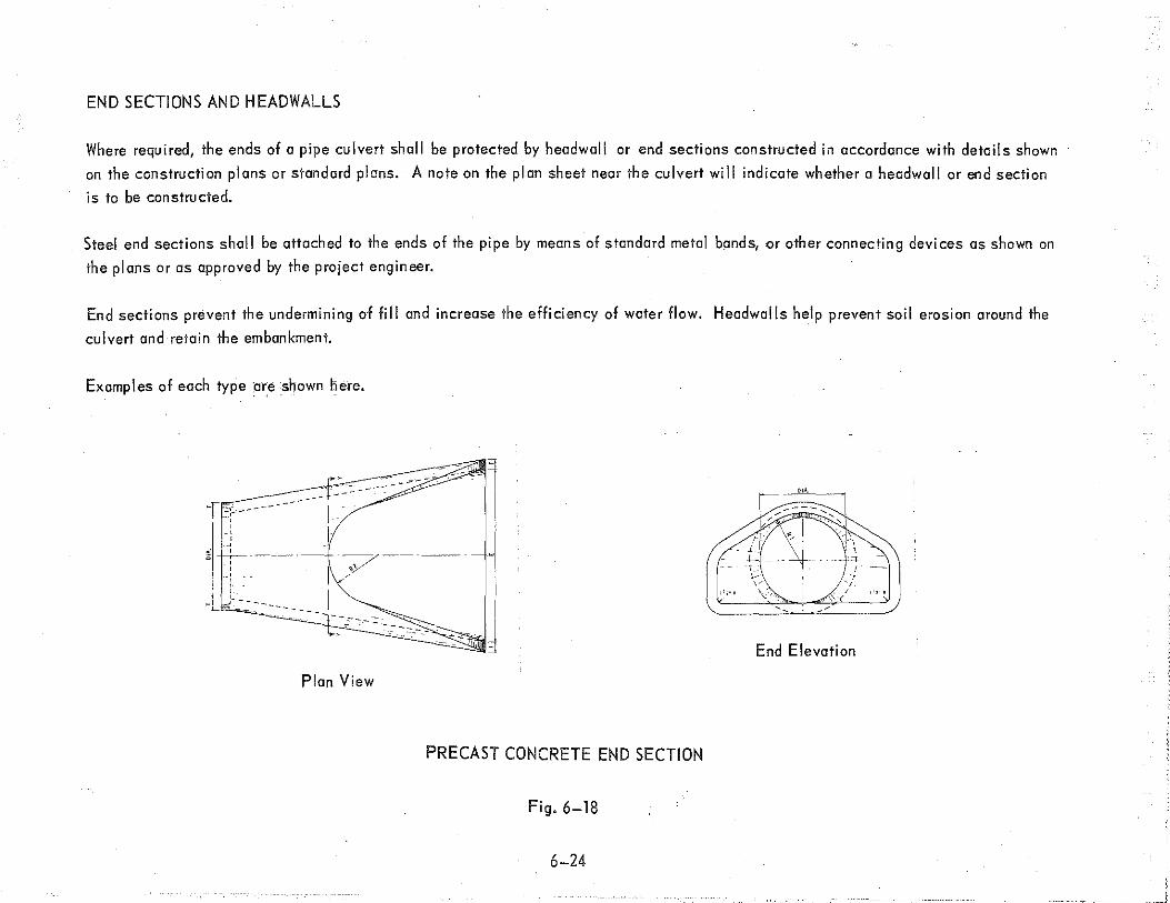
END SECTIONS AND HEADWALLS
Where required, the ends of a pipe culvert shall be protected by headwall or end sections constructed in accordance with details shown
on the construction plans or standard plans. A note on the plan sheet near the culvert will indicate whether a headwall or end section
is to be constructed.
Steel end sections shall be attached to the ends of the pipe by means of standard metal bands, ,or other connecting devices as shown on
the plans or as approved by the project engineer.
End sections prevent the undermining of fill and increase the efficiency of water flow. Headwalls help prevent soil erosion around the
culvert and retain the embankment.
Examples of each type :are shown here.
End Elevation
Plan View
PRECAST CONCRETE END SECTION
Fig. 6-18
6-24

PLAN VIEW
FRONT ELEVATION
Head Wall
Wing Wall
Apron
HEADWALL FOR CIRCULAR PIPE
Fig. 6-19
6-25
•·
LONGITUDINAL SECTION

BOX CULVERTS
Box culverts are box-shaped openings under the roadway constructed with reinforced concrete and the ends are similar to a headwell
in construction. 1 The details for the construction of box culverts are shown on the plans.
Fig. 6-20
6-26
.-.·-::-:t:

SLOPE PROTECTION
This work shall consist of all necessary excavation and disposal of excavated material, and of constructing, to the lines shown on the
plans, a protective covering of the type shown on the plans on a prepared foundation, ,including headers along the edges of the slope
protection, when specified.
Slope protection shall consist of the following types:
Precast Concrete Slope Paving
Concrete Slope Paving
Grouted Flagstone Paving
Heavy Concrete Slope Paving
Grouted Riprap
PI a in Rip rap
Heavy Riprap
Rip rap consists of a layer of stones, or sound pieces of broken concrete. , The stone for riprap shall be sound, tough, durable rock, .
free from structural defects, or solid precast concrete blocks.
The profile sheet will indicate where sod is to be used and that all unsodded slopes and ditches shall be mulched.
6-27

The final major highway construction operation is paving. This work consists of placing the pavement structure upon the subgrade.
The pavement structure consists of the subbase, base course, shoulders or curbs and gutters, and the surface course. The speci fica
lions give complete requirements for the construction of each of these items of work. The word "metal": is used to describe a bitum
incws or concrete pavement surface. The edges of the pavement surface are called "edge of metal'.'
Pavement Structure
r-~---------------'- Roodbed ---------~--fl~ t--shou lde.-o ---<11!,. .. 1-Lr:sOII-------- Metal ---------<ll!""ooi'ioloa-Shou lder~
p-avement·
__. Bas·e Cou~ [ Clay Shoulder Point
.. Subbase
'Subgrade ./
I 1 l
~--------------------Earth Grade------------------------<ll!ooi
ROAD SECTION
Fig. 7-1
7-1
SUBBASE
The subbase is the layer of specified material, 'usually sand, ,of designed thickness placed on the subgrade .. The subbase material
shall be evenly spread and compacted to 95 percent of maximum unit weight.
Subbase may be placed in one layer, provided the depth of the compacted layer does not exceed 15 inches. Where the depth of sub
base called for on the plans or in the proposal is in excess oilS inches, ·such material shall be placed in layers of approximately
equal thickness.
Unless other wise provided, the subbase shall be constructed to the grade and cross section as shown on the plans, and trimmed to
within'% inch of the established grade.
When the contract includes surfacing or base course, ·the subbase shall be placed at least one mile in advance of placing the sur
facing or base course, if feasible.
The thickness of sand subbase required is shown on the typical section and varies according to the type of pavement section to
be constructed.
Should the subgrade, at any time prior to or during the placing of subbase, ·become soft or unstable to the extent that rutting occurs in
the subgrade, or to the extent that subgrade material is forced up into the subbase material, the operation of hauling and placing subbase
material shall immediately be discontinued and the condition corrected. After the subgrade has been corrected, as directed by the project engineer, new subbase material shall be placed and compacted.
Subbase shall not be placed on a frozen subgrade unless approved by the project engineer. If subbase is placed on a frozen subgrode,
the subbase shall be tested for density in the Spring. Any damage to the subgrade or subbase caused by equipment operation on the subbase shall be corrected.
7-2

BASE COURSE
The base course is the layer or layers of specified or selected materials of designed thickness, as shown on the typical section, placed
on a subbase or a subgrade to support a surface course. The material lor the base course may be either aggregate lor bituminous or
concrete as specified on the typical section.
The construction method to be used in placing an aggregate base course depends on whether it is to support a bituminous surface course
or a concrete surface course.
The completed aggregate base course shall be maintained with graders in a smooth, compacted condition, substantially to line, grade
and cross section until the surface treatment is applied, or the surface is accepted. The application of water may be required to
facilitate reshaping the compacted surface prior to surface treatment or acceptance.·
The work in placing a bituminous base course·shall consist of conditioning the foundation and constructing one or more layers of pi ant
mixed bituminous mixture on the subgrade, 'or on an existing pavement, prior to the placing of bituminous surface courses.
SHOULDERS
The shoulder of a road is the portion of the roadway contiguous with the traveled way for accommodation of stopped vehicles, for
emergency use, and for lateral support of base and surface courses.· The material for shoulders may be aggregate, ,bituminous or con
crete as specified on the typical cross section.
Aggregate shoulders shall consist of an aggregate or earth surface, of the class called for on the plans, constructed on a prepared
subgrade. Shoulder construction is divided into the following classes based upon different quality of materials: Class AA, Class A,
Class B, and Class D.
Shoulders may be constructed of bituminous or concrete mixtures as specified or permitted. When freeway shoulders are specified, the
contractor may construct either the full depth bituminous or concrete shoulder alternate.
7-3

The type of shoulder proposed is shown on the typical cross section. Here are two typical shoulder cross sections.
Yl" !ft.-~~
CLASS A SHOULDER
r-··:.•: -:·.,;·:=:~·.- ... ···::· .... · .. ~=:-:i)dd{k>\;ii{iZd ~ ---22A Aggregate
Bit. Agg. . : 170#/S. Yd. ~ f!2'l
; Yz"!ft.-
CLASS AA SHOULDER
Fig. 7-2
7-4

SURFACE COURSE (Pavement)
The surface course is the top layer of the pavement structure. There are two types of pavements, ·flexible and rigid.
A II exi bl e pavement surface course is constructed of bituminous materials.
A rigid pavement surface course is constructed of portland cement concrete.
A bituminous paving operation consists of preparing the foundation and constructing thereon one or more layers of hot plant-mixed
bituminous aggregate or bituminous concrete pavement, ·which is the surface course. This surface may be constructed of a leveling
course and a wearing course. The application rates are specified on the typical cross section. The type of pavement used is shown
on the typical cross section as shown here.
6!4'' (Typ.)
SHOULDER NOTE:
Bit. Agg. Shld.
Est. 130#/S Yd. (lW')
Bit. Bond Coat
Est. 0.10 Gai./S. Yd.
Bit. Base-Plant Mix
Est. 550#/S. Yd. (5 ")
Misc. Cone. P:av't.
9" Unif.
(Rein f.)
0.15"/ft.-
10" Subbase
Alignment Edge
Class AA Shoulder
72"/ft.
Agg. Base Course for Cone.·
Est. 4 "(3'' Min. :after Final Shaping)
RIGID PAVEMENT SECTION
Fig. 7-3
7-5

•
Bit. Agg. Shld. ·
Est. 170#/S Yd.
CJ ass AA Shl d.
- 0.15"/ft.
~18" Subbase
Bit. Cone. Wear. Course Est. @ 120# /S Yd.
Bit. Cone. Level Course Est.@ 130#/S Yd.
Bit. Base Course Est.@ 440#/S Yd.
Bit. Bond Coat Est.@ 0.10 Gal./5 Yd.
!:2 "/ft. -4" Unil. Agg. Base for Bit.
FLEXIBLE PAVEMENT SECTION
Fig. 7-4
A concrete paving operation consists of constructing a jointed portland cement concrete pavement, with or without reinforcement, as
specified. Either conventi anal form, or slip-form method of construction may be used.
Joints in concrete pavements shall conform to the details, positions, and spacing shown on the plans or standard plans. The various
types of joints are as follows:
1. Longitudinal lane tie joints with tie bars
2. Longitudinal bulkhead joints
3. Transverse contraction joints
4. Transverse expansion joints
5. End-of-pour joints
6. PI one-of-weakness joints
7-6

Typical jnint I ayout ond information is found either in special detail sheets in the construction plans or the standard plans. A note on
the typical cross section sheet will indicate which standard plan sheet is used.';
Concrete widening headers are used where the pavement tapers to less than 2ft. in width. This is to prevent the tapered edge from
breaking off or pulling away from an adjacent slab. A typical concrete widening header is shown here.
Header Depth Shall be the Same as Existing or New Pavement
Fig. 7-5 .
7-7
Hook Bolts Spaced
Edge to 1!4'''
Edge Full Length
of Header
CONCRETE WIDENING HEADERS
DEP ENT OF
48909

As soon as possible after paving operations start, the pavement surface will be tested for trueness by means of a ten-foot straightedge.
If an excessive number of depressions or high spots exceeding 1/8 inch in ten feet are found, paving operations shall be suspended and
corrections made to the finishing procedures. Paving operations may be resumed when approved by the project engineer.
As soon as the concrete has set sufficiently to maintain a texture, the concrete surface is thengrooved. The grooves shall be oriented
generally perpendicular to the centerline.
Survey station numbers shall be stenciled into the pavement concrete about one foot from the edge of metal.· On two way pavements,
the station numbers shall read in the direction of stationing on the.side of the road with the same traffic direction. On divided highways,
they shall read in the direction of traffic for each pavement.:
In the c(lse of a pavement with curb and gutter, the station numbers are stenciled into the gutter concrete instead of the pavement slab.
After finishing operations have been completed and immediately after the free water has left the surface, ·the surface of the concrete
pavement slab ·and the sides of the slab, in the case of slip-formed pavement, shall be completely coated and sealed with a uniform
layer of membrane curing compound. The sides of a conventional-formed pavement slab shall be coated with curing compound immediately
after forms are removed.
PAVEMENT ELEVATIONS
The steps for determining pavement elevations are shown here. Use the E. Bd. pavement at Sta. 1220 + 50, example plans, and
Fig. 2-6 as the typical.
Steps 1-8: Determine plan grade and crown point location
(Same procedure as on page 5-11 )
7-8

Step 9: Determine pavement elevation at crown point
Plan Grade El. 663.80
Vert. dis!. from P.G. to Crown Pt.
12' X 0.015'/ft. =0.18
Crown Point El. 663.80 + 0.18 663 .. 98
The pavement elevations at any other points, such as ioints and edge of metal, may be determined from the crown point or plan grade I
point elevation by applying the standard pavement slope of 0.015 /ft. for normal sections.:
Example: For the Rt. edge of metaf the horizontal distance from the
crown point is 24ft. thus the crown drop= -0.015'/ft. X 24' = 0.36'
Crown El.
Rt. EOM
663.98 -0.36
663.62
7-9

Plan Grade Point Lt. EOM
663.80
12'
/ Crown Point 663.98
P .G. El.
P .G. to Crown 12' X+ 0.015' =
Crown El. ·
Crown to Rt. EQM 24' X- 0.015' ~
Rt. EOM E\.
24'
0.015'/ft.
663.80
+ 0.18
663.98
~o.36
663.62
PAVEMENT ELEVATIONS-NORMAL SECTION
Fig. 7-6
7-10
Rt. EOM 663.62
I

For a superelevated section you would use the rate of super indicated in the plans.
Plan Grade Point Lt. EOM
663.80
CURB AND GUTTER
36'
6'/h 'Super- 0.0 · Rate oT -
P.G. El. 663.80
P.G. to Rt. EOM 36 x0.06'/ft. = + 2.16
Rt. EOM El. 665.96
PAVEMENT ELEVATIONS-SUPERELEVATED SECTION
Fig. 7-7
J
Rt. EOM
665.96
Curbs may be constructed with bituminous or concrete mixtures. When constructed of concrete, ·usually a gutter is poured with the curb
and the combination is called curb and gutter. It is abbreviated by C & G. The proposed C & G details are specified on the Typical
Cross Section and Plan Sheets. See Sheet No. 11-30B of the Stan~ard Plans for Curb and Gutter details A,B,C,D, E and K which give the
necessary dimensions for construction.
Concrete curb and gutter work shall consist of constructing portland cement concrete curb, gutter, combination curb and gutter, shoulder
gutter, downspout headers, •Spillways, and dividers, of the detail specified, on the prepared base.
7-11

26 27 28 29 30 31
Concrete Curb and Gutter Detail Bl
1,000 L. Ft.
CURB AND GUTTER (Detail Bl)
Fig. 7-8
Curbing shall be either reinforced or continuously reinforced, ,as provided. Backfilling will be part of constructing curbing unless
otherwise provided.
Unless otherwise specified, the contractor may construct concrete curbing mechanically or with forms, ·and either by casting separately
or as an integral part of a concrete pavement, provided that the required cross section and finish ore obtained.
Joints in concrete curb and gutter shall be constructed perpendicular to the surfaces of the structure. Contraction joints, plane-of
weakness joints, and expansion joints shall be constructed as shown on the plans. Expansion joint filler shall extend to the full depth
of the joint, and the top shall be recessed 1/4 to 1/2 inch from the finished surface of the structure.
Joints for continuously reinforced concrete curb and gutter shall be constructed as shown on the plans.
The complete surface of the concrete structure shall be coated and sealed with curing compounds.
7-12

The proposed C & G details are specified on the Typical Cross Section and Plan Sheets. See Sheet No. 11-30B of the Standard Plans
lor Curb and Gutter details A, B, C, D, E and K which give the necessary dimensions for construction.
7-13

A bridge is a structure with a total clear span of more than 20 feet measured along the centerline of the roadway, over a stream,
watercourse, or opening. When used in a general sense, the term bridge includes grade separations.
This chapter covers bridge terminology and the details of reading bridge plans. In a set of construction plans which includes both road and bridge plans, .the bridge plans always follow the road plans.
BRIDGE STRUCTURE
The structure of a bridge consists of two main parts:
1. Substructure
2. Superstructure
The substructure is the foundation of the bridge. It supports the superstructure. It is everything below the superstructure.
The superstructure is what spans whatever the bridge is crossing. It supports the roadway.· It is everything above the substructure.
8-1

I
I
,. '
The figure below shows the substructure and superstructure of a bridge.·
Approach Roadway r- Rei, line A
I
Span
ABUT A
BRIDGE ELEVATION
Fig. 8-1
8-2
Superstructure <t_ Pier-·
~f~~~~
R.G. Substructure
,-- .... ---._-- --'
PIER

SUBSTRUCTURE
The substructure of a bridge consists of two main parts:
1. Abutments
2. ·Piers
Abutments are bridge supports located at the bridge ends. They support the end points of the superstructure and retain the earth fills
for the bridge approach roadways.
Piers are bridge supports located between the bridge ends. They support intermediate points of the superstructure.
These substructure units are usually constructed with reinforced concrete. They will be covered in greater detail later on in the chapter.
SUPERSTRUCTURE
The superstructure of a bridge consists of two main parts:
1.. Bridge Frome
2. Bridge Deck
The bridge frame sets on the substructure units and supports the bridge deck~ It consists of several structural members framed together.
The arrangement of these members may be s·imple or complex, depending upon the size of the bridge. Usually structural steel is the
material used to construct the bridge frame.
The bridge deck is attached to the bridge frame and supports the roadway traffic. ·It is usually constructed with reinforced concrete.
· These superstructure units will be covered in greater detail later on in the chapter.
8-3

Ref. Line A
Bridge
Canst. ~
L_
~ Brg ~ Pier & Brg.
60" Welded Plate Girders
lntermedi ate Cross Frames
FRAME ERECTION DIAGRAM
Fig. 8-2
8-4
~ Brg
Ref. Line B
Lateral Bracing (typ.)

Slab
I[ Girder (typ.)
r Bridge Canst. ~ I
I
I '
I
SECTION THRU DECK
Fig. 8-3
8-5
Framing Members

BRIDGE PLANS
Now that you have an understanding of the basic components of a bridge, we will go through a set of bridge plans and cover !he major
details shown on each sheet. Knowledge of these details will enable you to read any set of bridge plans.
The index of sheets below lists the plan sheets included in your example set of bridge plans. This index is always given on !he title
sheet. Refer to these sheets as you read the text.
INDEX of SHEETS I SHEET NO. DESCRIPTION I
I TITLE SHEET Ia QUANTITY SHEET 2 GENERAL PLAN OF SITE 3 LOG OF BORINGS
4,5 GENERAL PLAN OF STRUCTURE i 6 GENERAL PLAN OF STRUCTURE- EXISTING '
LiJ 7, 8.9 ABUTMENT A DETAILS - 10,11,12 ABUTMENT B DETAILS N 13 14 PIER DETAILS 0 15,16,17 STRUCTURAL STEEL DETAILS
' N 18,19,20 SUPERSTRUCTURE DETAILS I w 21,22 SUPERSTRUCTURE DETAILS ' 23 BAR SCHEDULE I .... 24 GENERAL PLAN OF TEMPORARY STRUCTURE 0
25 SUPERSTRUCTURE AND STRUCTURAL STEEL ! - DETAILS- TEMPORARY STRUCTURE 0 26 TEMPORARY BRIDGE PILE BENT DETAILS en
Fig. 8-4
Notice that only one of each type of sheet is used as on exompiEl.in the example plans.
8-6

TITLE SHEET
The Title Sheet gives general bridge data. In the center is a strip map of the area where the bridge is to be located. The proposed
bridge is identified by the bridge number in a box with an arrow pointing to the location on the strip map.
Example: ~50--clo---o-c-f -,-8cc-20~2cc-1
The letter in the bridge numbersignifies the type of bridge; the two digit number alter the letter is the bridge index number; the five
digit number after "of" is the control section number.
The different types of bridges are as follows:
1. Highway over water:. - B for bridge .
2. Highway grade. separation - S for separation
3. Highway over or under a rai I road. -X for rai I road
4. Pedestrian bridge - P for pedestrian
Thus, the example bridge number above reads: Grade separation No. 1 of Control Section No. 82021. Since the index number is a two
digit number, it would be possible to have 99 grade separations. Example: 599 of 82021. ·Other examples are: B01 of 82021, X01 of
82021, POl of 82021.
The Index of Sheets is shown in the upper left hand comer.
The General Notes are I isted in the upper right hand corner. Here the Specifications governing the work are stated along with the grades
of materials ond the design stresses to be used in the structure. The design stresses are in "pounds per square inch" abbreviated "psi."
The Standard Plan Sheets to be printed and included in the set of bridge plans are listed in a table in the lower left hand comer.· These
always. come after the last sheet number listed in the Index of Sheets.
The title block is in the lower right hand corner and at the top of it is listed what the contract is for, in this case, ·BRIDGE.
8-7
QUANTITY SHEET
The quantity of work for each pay item in the bridge contract is listed in tabular form on the Quantity Sheet. There are two quantity
columns in the table:
1. Contract Quantities- These are the estimated quantities of work upon which the contract bids were made.
2. Final Quantities -These are the actual quantities of work done by the contractor.·
The final cost for each item of work is determined by multiplying the final quantity by the unit price. The contractor is paid this
amount if the work is acceptable.
GENERAL PLAN OF SITE SHEET
The General Plan of Site Sheet gives more specific bridge data. The following items are shown:
1. Situation PI on - plan view of the bridge site.
2. Profile- along the center! ine of the bridge.
3. Profile- along the centerline of whatever the bridge crosses.
4. Alignment Sketch- shows relationship between the bridge centerline and the centerline of whatever the bridge crosses.
5. Approach Section -typical section of the bridge approach.
6. Traffic Distribution - estimate of traffic 20 years in the future.
7. Bench Mark Data - same as on road pi ens.
8. ·Utilities Data -same as on road plans.
9. Witnesses Data - same as on road pi ans.
10. Notes -describe the work covered by the bridge plans.
The Situation Plan is similar to the plan view shown on a Plan and Profile Sheet in a set of road plans. The following items ore shown:
1. North Arrow -for orientation of the plan view.
2. Plan View of the proposed bridge which is identified by:
PROPOSED STRUCTURE
3. Centerlines- survey centerlines, bridge centerlines, and centerline of whatever the bridge crosses, with station numbers.
8-8

4. Reference Lines and Reference Points- the abutments are labeled Abutment A and Abutment Bin the direction of in
creasing stationing. The backs of the abutments are Reference Line A and Reference Line B.
The piers are labeled Pier 1, Pier 2, etc. in the direction of increasing stationing. The centerlines of the piers are
Reference Line l, Reference Line 2, etc. The points of intersection of the bridge centerline and the pier reference lines
are Reference Point 1, Reference Point 2, etc.
The Skew Angle is the angle .between the bridge centerline and the reference lines. The bridge is the shortest when the
skew angle is 90• .
5. Contour Lines- the elevation is constant along a given contour line. The shoreline of a lake is an example of a natural
contour line. By studying a series ofcontour lines, ,the natural slope ol the ground can be determined. The contour interval
is the difference in elevation between adjacent contour I ines.
6. Proposed Slopes -the various slopes lor the grading around the bridge are shown in this way:
..0
c: 0
Fig. 8-5
8-9
Rate of Slope
The short line indicates the top of slope •

7. Test Holes- Bridge Design personnel determine the location for test holes, <Jsually one at each abutment and pier. A
drawing showing the station and distance out from bridge centerline for each test hole is given to Soils Division personnel
who make test hole borings to determine the soil conditions under the bridge. This soil data is used to make a determine·
tion of the type of bridge foundation to be used. If the soil has good bearing capacity, spread footings are used. If the
soi"l has poor bearing capacity, footings supported on piles are used.
The test hole locations are marked by this symbol: 0 T.H. :#3 (Test Hole No.3)
8. Utilities- existing utilities and proposed adiustments are shown with standard symbols as on road plans.
9. Drainage- existing and proposed drainage systems are shown as on road plans.
10. Notes- specific information pertaining to the construction of the bridge.
The Profile of the bridge centerline shows the elevation view of the bridge and its approaches, and a section view of whatever the
bridge crosses. The items shown are as follows:
]. "Grades- the percent grade of the proposed bridge centerline is indicated as on road plans. If the bridge is on a vertical
curve, ,that data is also given.
2. Existing conditions -the profile of the existing ground or existing road is shown.
3. Span lengths -the length of each span and the total structure span length are indicated. The span lengths are the
distances between successive reference points.
4. Reference points- the reference points are labeled and the station and plan grade elevation for each is given.
5. Limits of backfill- the limits of the granular material used to backfill behind the abutments are shown.· The class of
material to be used and the estimated quantity are also given.
6. ·Slopes- the slopes in front of the abutments and the slopes of the backfill limits are indicated.
7. Footings - the elevations of the bottom of abutment and pier footings are given. ·
8. Piles- if the abutment and/or pier footings are to be supported on piles, ,the type of pile and the pile load capacity
are noted.
9. Underclearance- the minimum underclearance distance is giv~n. 10. Drainage- drainage pipes and/or other drainage structures are shown.
8-10
-~

The Profile of the centerline of whatever the bridge crosses shows the proposed bridge in section view, and the minimum under
clearance distance.
The Alignment Sketch has a north arrow for orientation and shows bearings, distances and stationing which are used in preparing a
stake-out diagram for bridge construction.
The Approach Section shows all the details for constructing the bridge approach roads. It is the same as a Typical Section shown on
road plans.
The I_raflic Distribution Sketch gives information regarding the estimated traffic 20 years in the future. Figures for both average doily
traffic (A.D.T.I in vehicles per day (v.p.d.) and daily hourly volume (D.H.V.) in vehicles per hour (v.p.h.) are for all possible traffic
movements. Figures for existing A.D. T. are also given. This traffic data is compiled by the Traffic Division.,
LOG OF BORINGS SHEET
The soil data gathered from the test hole borings is presented on the Log of Boring Sheet. The location of the test holes is shown on
a Boring Location Sketch ,which is oriented with a north arrow. The station and distance out from centerline is indicated for each
test hole.
, The information determined about the soil from the borings is summarized on the soil profile for each test hole. ';
8-11

Example:
El. !.II+. I
EA!l. 2.6'
w.rier to,... """" ~- .M<ir · . ~+ion U:-1~ ~-'"'·do?· :w lir. do-y. . ..
Fig. 8-6
As noted in the example, the encircled numbers are blow counts which give an indication of the hardness of soils. The numbers denote
the number of blows required to drive a 2.0" O.D. x 1.5" J.D. split spoon 12" (6" increments) using a 140 lb hammer falling 30".
Example:
Lib QD It took 12 blows to go the first 6".
It took 19 blows to go the second 6".
(It took 31 blows to go the full 12")
Normally, the higher the total number of blows, the harder the soi I, and the lower the total number of blows, the softer the soil.
The notes above the title block describe the blow count numbers.
8-12

GENERAL PLAN OF STRUCTURE SHEET
More details about the bridge structure are given on the General Plan of Structure Sheet.; The following items are shown:
1. ·Plan- similar to the plan view on the General Plan of Site Sheet, .but drawn to a larger size for more clarity of detail, and
showing more details and dimensions.· The location of detail sections are indicated by this symbol: ~f AI~ 2. ·Elevation- similar to the profile of the bridge centerline on the General Plan of Site Sheet, but drawn to a larger size for
more clarity of detail, and showing more details and dimensions.
3. Sections- several detail sections are show;, for different parts of the bridge in order to clearly define how it is to be constructed in general. Such things as limits of earth excavation, foundation .drains, ·construction joints, and structural
dimensions are shown.
4. Miscellaneous Quantities- table of quantities of miscellaneous items of work.
5. Notes- describe the Design Specifications, ·the type of structural steel members, and other miscellaneous information.
ABUTMENT DETAILS SHEET
There are three types of abutment designs which are illustrated in the figures below:
Wall Wall
Counter for
T Abutment
Cantilever Abutment Fig. 8-7
8-13
-Curtain Wall Abutment·
(always on piles)
Curtain Wall

Only the cantilever (stub! .abutment will be covered in the text. Usually slope walls or wingwalls are attached to the ends of the
abutment to assist in retaining the earth fill behind the abutment. The ligures below show both.
Earth Slope ... Footing
Wall
Plan
j... Superstructure Width ..j
Bridge Seat
Elevation
SLOPE WALLS
Earth Slope . l nee Refere
Line 1---=
Slope Walls
Wall -1110
Footin g~
Fig. 8-8
8-14
.---
.r-
(""' r-Wall
I
' f- I-
' ~ .
Plan
)l'ling . Walls
r Superstructure Width
~ Bridge Seat ~
'-
I Elevation
WING WALLS

There are two ways of retaining the portion of the earth fill which is above the abutment wall across the superstructure width.
These are:
1. Dependent Backwall - a wall constructed as part of the superstructure.
2. Independent Backwall -a wall constructed as part of the abutment wall.
The ligures below show each;
~Ref. Line
I Bridge Deck Approach Pavement ·
Bridge frame --~
Slope Protection··
I
:J
Pavement Seat
Backwall
Abutment We II
Abutment
,.---1""'-~L--..f-----, Footing
DEPENDENT BACKWALL
Bridge Frame
Slope Protection ~ .
Fig. 8-9
8-15
Bridge Deck
pl. Line
Approach Pavement
(
Pavement Seat
Backwall
Abutment Wall
Abutment Footing
INDEPENDENT BACKWALL

The abutment Details Sheet shows all specific details necessary for the construction of the abutments. The items shown are as follows:
1. Wall Plan- plan view of the abutment wall, •With slopewalls or wingwalls, if any, ·showing a north arrow, ·the bridge con
struction centerline, ·reference.line, •reference point, ·skew angle, beam centerlines, centerline of bearing, •anchor bolts,
construction joints, -joint filler, •joint waterproofing, locations of detail views, and structural dimensions.·
2. Footing Plan- plan view of the abutment footing showing a north arrow, the bridge construction centerline, ·reference line,
reference point, .skew angle, .wall outline, ·Construction joints, limits of unclassified excavation, locations of section views,
structural dimensions, steel reinforcement placement layout, and pile layout, if any.·
The steel reinforcement layout includes information about reinforcing bar spacings, marks, sizes, .and laps, which are
determined by design criteria. Example:
---------- On I!' the end bar--.........___ ¥ 1sshown ~
. 11 Spa.@ 1'-16" = 16'·6"
A9 Bars #7
~ \ Bar Mark Bar Size
Fig. 8-10
~ Bar Spacing
Only bar spacing information will be covered here. An explanation about bar marks, sizes, and laps is included later on
in the text with the information about the Steel Reinforcement Details Sheet.
8-16

The spacing of the steel reinforcing bars is designated by the number of spaces, the length of each space and the total
distance. Example: 11 spa.@ 1'- 6" = 16'- 6" which means: '- 11 - the number of spaces,
spa. - the abbreviation for spaces @ - symbol· meaning "at"
1 '- 6" - length of one spC!ce = 16'-6"- total distance
and is read: 11 spaces at 1'_: 6" equals 16'- 6".
There are longitudinal and transverse bars placed horizontally in the top and bottom of the footing. Vertical bars for the
front and back of the abutment wall are placed with the footing bars to tie the wall and looting together. These bars
project out of the footing concrete after it is poured.
3. Elevation- elevation view of the abutment showing the designations of concrete pours, construction joints, joint filler,
joint waterproofing, anchor bolts, -bolster heights, ·lop of concrete elevations, haltom of footing elevation, ·Structural
dimensions, steel reinforcement information, ·and pile information, if any. Concrete pours are designated Pour A,
Pour B, etc.
4. Sections- detail sections of various parts of the abutment showing structural dimensions, ·steel reinforcement infor
mation and other details. They are designated as Section A-A, Section B-B, etc.
5. Details- enlarged views for clarity of detail. They are designated Detail A, Detail B, etc.
6. Anchor Bolt Projection Table- gives the distance in inches that the anchor bolts should project out of the abutment
wall concrete at the location of each beam or girder.
7. Substructure Concrete Quantities- the grade and quantity of concrete in cubic yards for each pour is given in tabular
form. The grade of concrete is based on the aggregate used and amount of cement to be used per cubic yard of concrete.
8. Miscellaneous Quantities- table of quantities of miscellaneous items of work.
9. Pile Quantities- tables of pile quantities and miscellaneous pile information like size of piling and required wall
thickness of pipe piling may be here or in the notes.
10. Notes- give meaning of abbreviations, ·Soil pressures and other information. The soil pressures are based on dead
load (D.L.) only and on a combination of dead load and live load (D.L. and L.L.). Dead load is the weight of the
bridge and live load is the traffic load carried by the bridge.
8-17

PIER DETAILS SHEET
The typical bridge pier consists of the three components illustrated
in the figure below:
TYPICAL PIER
Cap
Column
Footing
Fig. 8-8
8-18
The Pier Details Sheet shows all specific details necessary for the construction of the piers. The items shown are as follows:
1. Cap Plan.
2. · Footing PI an. ·
3. Elevation
4. End View
5. Sections
6. Details (including steel reinforcement sizes and layout)
7. Anchor Bolt Projection Table
8. Substructure Concrete Quantities.
9; Miscellaneous Quantities.
10. Notes.·
An explanation for each of these items is not given above, ·because they are similar to the items explained in the text about the Abut
ment Details Sheet. Compare the Abutment Sheets in the example plan to see the similarity.
The reinforcing steel bars lor the cap and columns are usually prefabricated into cages on the ground at the bridge construction site
and then placed by a crane.
STRUCTURAL STEEL DETAILS
The typical structural steel bridge frame consists of longitudinal stringers, which span the distance between abutments and piers,
· connected by transverse members, called diaphrams at intermediate points along their lengths.
8-19

The figure below illustrates a structural steel bridge frame.-·
Exterior Stringer (FASCIA)
Pier
Fig. 8-9
Interior Stringers
Abutment
Exterior Stringer
(FASCIAl
Intermediate Diaphrams
TYPICAL BRIDGE FRAME
8-20
---,.;

The stringers are either ;oiled beams or welded plate girders.: The figure shows each of these:
Top Flange
Web...:.
Bottom Flange
ROLLED BEAM
\..\... \...
Bottom Flange It
Top Flange If.
Fig. 8-10
Intermediate Stiffener It
Bearing Stiffener If.
WELDED PLATE GIRDER
Rolled beams come from the steel rolling mills in sizes up to 36" deep.: A typical rolled beam designation is as follows: W 30 X 116.
TheW stands for wide flange beam, the 30 is the nominal depth of the beam in inches and the 116 is the weight of the beam in pounds
per foot. Sometimes cover plates are welded to the flanges to increase the beam strength.
8-21

When greater depths are required, ·welded plate girders are used. Plate girders are fabricated by welding the flange plates to the web
plate. They may be 12 feet or more deep. The web plate is stiffened by welding stiffener plates to the flange plates and web plate.
Field splices are necessary for long plate girders because of transportation limitations. The abbreviation for plate is I('·,.:_
The bridge frame sets or bears on the abutments and piers, so bearing assemblies must be provided. There are two types:
1. ·Fixed- the bridge frame is anchored to the abutment or pier so it will not move.
2. Expansion - the bridge frame is allowed to move due to temperature change.
Some example bearing details ore shown in the.figures below:
Rolled Beam or Plate Girder) r Ci_ Girder
t~· ; ::t Pads or',
Lead Shims
Anchor Bolt
'I I I
'' ' ' '
Sole Plate
FIXED ABUTMENT BEARING
Expansion
Fig. 8-11
B-22
Sole Plate
I ·' I Fixed
PIER BEARING

Sometimes the bridge frame of one span is suspended or hung from the bridge frame of the adjacent span or spans, which cantilevers
beyond the pier. A suspender assembly is then required at each of the stringers. The figure below shows this:
Anchor Span
Abut. A
· Span 1
Conti lever Distance
Pier 1
Suspended Span
Suspended Assembly
Span 2
SUSPENDED SPAN
Fig. 8-12
8-23
Cantilever Distance
H
Pier 2
Anchor Span
Abut. B
Span 3

A typical suspender Assembly is shown below:
~ ;.:;:; fQ ~
I'---Pin
'\ ' ' ' ' ' ' ' ' ' ~
.
link It ---...__. ' - ~
"" 0. ""' 7
Suspended Span Anchor Span
SUSPENDER DE TAlL
Fig. 8-13
8-24

, .. _·-:''
The structural steel details sheet shows all the specific details necessary for the fabrication and erection of the structural steel
bridge frame which includes the following items:
1. Erection Diagram - d plan view of the bridge frame showing the mark of diaphrams, span lengths, and other dimensions
and detai Is necessary for the erection of the structural steel bridge frame. Stringers are marked as shown on the structural steel detail sheet.
2. Stringer Details- plan view and elevation view of a typical stringer for each span showing all dimensions and details
necessary for fabrication. Also, the bearing and suspender assemblies areshown.
3. Diophram Details- detailed views of the diaphrams showing all dimensions and details necessary for fabrication.
4. Anchor Bolt Details - detailed view of an anchor bolt.
5. Bearing Details- detailed view of bearing assemblies.
6. Suspender Details- detailed views of suspender assemblies, if any.
7. Shear Developer Details- detailed views of shear developers, if any.
8. Splice Details- detailed views of web and flange field splices, if any.
9. Sections- section views of various parts of the bridge frame.
10. Details- enlarged views for clarity of details.
11. Camber Diagram -sketch showing the location and amount of cambedor the stringers. Camber is on upward deflection
of the stringer which is built in during fabrication. When the stringer is in place in the bridge frame and the concrete
bridge deck is poured, most of the camber is removed by dead load deflection. In other words, the stringers straighten
out. If no camber was used, the stringers would sag due to dead load.
12. Sole Plate Thickness Table
13. Miscellaneous Quantities Table
14. Notes
8-25

//,
SUPERSTRUCTURE DETAILS SHEET
This sheet shows all the specific details necessary for the construction of the reinforced concrete bridge deck which includes the
following items:
].
2.
3.
4.
5. 6. 7. 8. 9.
-~ 10. 11. 12. 13. 14. 15. 16. 17. 18. 19.
Plan - plan view of the bridge deck for each span showing reinforcing steel bar spacings, marks, and sizes, and other
dimensions and detai Is.
Typical Deck Section -section view of the bridge deck showing stringer spacing, crown slope, steel reinforcement in·
formation, and other dimensions and detai Is.
Typical, New Jersey Barrier Section- s~ction view of the New Jersey Barrier showing all necessary dimensions
and detai Is.
·Typical Backwoll Section- section view of the backwall showing all necessary dimensions and details.· Remember that
dependent backwalls ore a part of the superstructure whereas independent backwolls.are port of the abutments.
Typical Expansion Joint Section -section view of the expansion.
Typical Construction Joint Section - section view of the construction joint.
Sections- section views of various parts of the bridge deck, <labeled Section A-A, Section B-B, ·etc.
Details- enlarged views for clarity of detail, labeled Detail A, Detail B, etc.
Pou·r Diagram- plan view of entire bridge deck with the various pours labeled as Pour A, Pour B, ·etc.
Screed- a mechanically operated strike off unit for paving operations.
Screed Template Elevations- table of top of Slob elevations at several points along each line of stringers. _ . ...., 1'. '. .
Screed Rail- forming device along which the concrete placing and finishing equipment travels.
Bottom o'f''slab Elevations- diagram showing points where bottom of slob elevations ore given.
Top of Slob Offsets- diagram showing offsets from a straight line between support points and the top of slob.
Camber Ordinate Diagrams- diagram showing points along the stringers where camber ordinates ore given.
Camber Ordinate Table- table of camber ordinates for various stages of construction.
Superstructure Concrete Quantities.
Miscellaneous Quantities.
Notes.
8-26

STEEL REINFORCEMENT DETAILS SHEET
This sheet summarizes the data for furnishing all steel reinforcing bars required to construct the bridge. It shows the following items:
1. Bar Bending Diagram -a diagram which shows all the standard shapes for bent bars along with the general dimensions.
The various shapes are designated by letters, A, B, ·C, etc. The dimensions are labeled a, b, c, etc.
2.: Bar Schedule- a table of information lor all bars. A separate bar schedule. is given lor the abutments, piers, and super
structure. This information consists of the following items for each bar:
A. Mark- a combination letter and number which identifies the bar. The letter indicates the shape of the bar
corresponding to one of the various shapes shown in the Bar Bending Diagram. ·The number is an index
number which identifies each different length bar.:
B. :Dimensions ~the bar is bent according to the given dimensions.
C. Size- originally bars under 1" in diameter were round and larger bars were square. Today all reinforcing
bars are round.· The bar size is designated by a code number which denotes the number of 1/8". increments
in the bar diameter for bars up to 1 ''diameter.
Examples: #3 bar- 3/8" diameter bar.:
#4 bar - 4/8" = 1/2" diameter bar. :
#8 bar - 8/8 = 1" diameter bar.
For bars over 1" diameter, ,the code number has a little different meaning. A #9 bar has a diameter which
gives the same cross sectional area as the old 9/8" = 1 1/8 '' square bar; a# 10 bar has the same area as
the old 10/8" = 1 1/4 "square bar, 'etc.
D. Length- this is the length of the straight bar before bending it into the desired shape.
E~ Number Required- this is the quantity of bars required for the given shape and size.
F. Total Weight- this is the total weight of the specified bar obtained by multiplying the weight in pounds
per loot for the given size bar by the length of the bar by the number required. Also, total weight for all
abutment bars, all pier bars, and all superstructure bars.
3. Notes- describing specifications for bending bars.
4. Grand Total Steel Reinforcement Weight- total weight of all bars in the bridge.
8-27 48909.

ABSORPTION
ACCELERATION LANE &
DECELERATION LANE
ACQUISITION OR TAKING
APPENDIX A •
HIGHWAY TERMINOLOGY
The process of a solid taking up liquids by sur.face wetting and capillarity, as a sponge takes up water.
Both of these facilitiesare "speed change lanes or auxiliary lanes including tapered areas primarily
for the acceleration or deceleration of vehicles entering or leaving the through traffic lanes."
The process of obtaining right-of-way.
ADHESIVE --REFLECTOR- A coating provided on the back of reflective sheeting for highway traffic signs which forms a durable
IZED SHEETING
ADVERTISEMENT
AFFIDAVITS
AGGREGATE
AIR ENTRAINING
AGENT
APPRAISAL
bond to metal, wood, or other sign panel material.
The public announcement, as required by law, inviting bids for work to be performed and materials
to be furnished.
Written statements of fact, signed and sworn to by a person, hefore an officer authorized by law to ad
minister oaths--usually a Notary Public.
Rood materials composed of mineral substances, ·such as gravel, •crushed stone, slog, ·cinders, sand
or combinations thereof, used for various purposes in highway maintenance.
A substance used in concrete to increase the amount of entrained air in the mixture; entrained air is
present in the form of very small bubbles.
An estimate of quantity, quality, or value. The process through which conclusions or property
value are obtained; also commonly the report setting forth such estimate and conclusion and the dif
ferent variables and calculations used to reach such conclusion.
A-1
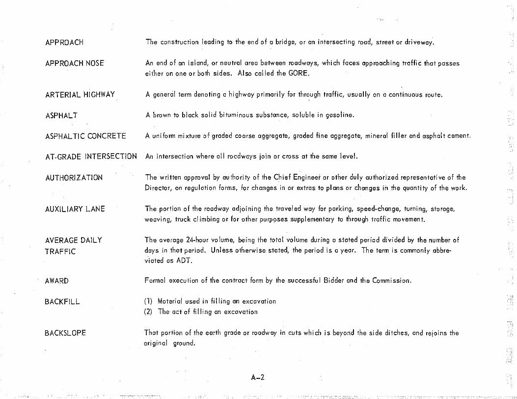
APPROACH The construction leading to the end of a bridge, or an intersecting road, stre.et or driveway.
APPROACH NOSE An end of an island, or neutral area between roadways, which faces approaching traffic that passes
either on one or both sides. Also called the GORE.
ARTERIAL HIGHWAY A general term denoting a highway primarily for through traffic, usually on a continuous route.
ASPHALT A brown to black solid bituminous substance, soluble in gasoline.
ASPHALTIC CONCRETE A uniform mixture of graded coarse aggregate, graded line aggregate, mineral filler and asphalt cement.
AT-GRADE INTERSECTION An intersection where all roadways join or cross at the same level.
AUTHORIZATION The written approval by authority of the Chief Engineer or other duly authorized representative of the
Director, on regulation forms, for changes in or extras to plans or changes in the quantity of the work.
AUXILIARY LANE
AVERAGE DAILY
TRAFFIC
AWARD
BACKFILL
BACKSLOPE
The portion of the roadway adjoining the traveled way for parking, speed-change, turning, storage,
weaving, truck climbing or for other purposes supplementary to through traffic movement.
The average 24-hour volume, being the total volume during a stated period divided by the number of
days in that period. Unless otherwise stated, the period is a year. The term is commonly abbre
viated as ADT.
Formal execution of the contract form by the successful Bidder and the Commission.
(1) Material used in filling an excavation
(2) The act of filling an excavation
That portion of the earth grade or roadway in cuts which is beyond the side ditches, and rejoins the
original ground.
A-2

BASE COURSE
BATCH PLANT
BENCHMARK
BERM
BETTERMENT
BID
BIDDER
BI-DIRECTIONAL
BINDER
BITUMEN
BITUMINOUS CONCRETE
The layer or layers of specified or selected material of designed thickness placed on a subbase or a
subgrade to support a surface course.
Equipment used to measure materials used in concrete or bituminous mixes.
A relatively permanent point of known or assumed elevation along the course of a survey line.
An approximate horizontal space introduced in a slope.
A major improvement of all or any part of a highway beyond the scope of routine maintenance.
The offer of a written contract price for a piece of property, or for doing work and/or supplying
materials.
The individual, partnership or corporation or any combination of any or all jointly, formally submitting
a proposal for the Work contemplated or any portion thereof, acting directly or through an authorized
representative.
Two direction traffic flow median crossover
A foreign material introduced into the mineral portion of the wearing surface to assist the road
metal to retain its integrity under stress, ,as well as, perhaps, to aid in its construction.
Any of several inflammable substances (Hydrocarbons), which may be liquid, ,semisolid, or solid. For
road maintenance work, bitumen commonly means any of several road oi Is, either asphalt or tar,
covered by various specifications.
A designed combination of dense graded mineral aggregate, ,filler and bituminous cement, mixed in a
central plant and laid and compacted while hot.
A-3

BLEEDING
BLOW-UP
BOND (COAT)
BOX CULVERT
BRIDGE
BRIDGE DECK
CALENDAR DAY
CAMBER
CATCH BASIN
CEMENT
CENTER LINE
The accumulation of excess bituminous material on the roadway surface, caused by heat or the use
of excessive quantities of bituminous material in patching or resurfacing.
Displacement of rigid type pavement by a combination of vertical and horizontal stresses due to
expansion. Generally speaking, a blow-up is a heave in a concrete or brick pavement caused by ex
cessive heat, sometimes resulting in chattering or displacement of the road surface.
The application of a liquid bitumen to cause a new surface to adhere to an existing hard surface.
Examples: RC-1, RC-2, T -3, ·AE-2.
A concrete culvert--rectangular in shape--having all four sides of concrete--i.e., concrete bottom
slob, two concrete walls,' and a concrete top slab.
A structure with a total clear span of more than 20 feet measured along center! ine of roadway, over a
stream, ·watercourse, or opening. When used in a general sense, •the term bridge includes grade
separations.
The port of a bridge floor that forms the roadway.
Every day shown on the calendar beginning and ending at midnight. '
Extra height provided in forms for arches or beams to allow for settlement of the forms due to the weight
of the fresh concrete.
A receptable for diverting surface water to a sewer or subdroin, having as its bose a sump to prevent the
admission of coarse material into the sewer.
The substance used for binding particles of aggregate together to form a pavement structure.
A line marking the center of a roadway on which traffic moves in both directions, or dividing the roadway
between traffic moving in opposite directions.
A-4

CHANNELIZATION
CLAY
CLEAR SPAN
CLEARING
CLEAR VISION CORNER.
CLOVERLEAF
INTERCHANGE
COFFERDAM
COLD JOINT
SEALING
COLD PATCH
The direction or separation of traffic flow into definite paths, by means of traffic markings, islands or
other means to facilitate the safe and orderly movements of bath vehicles and pedestrians.
A fine-textured s.oil, usually plastic and sticky when wet, ·and which usually breaks into hard lumps
when dry. When the moist soil is pinched between the thumb and finger, it will form a long, flexible
ribbon. Cloy is used as an admixture in the stabilization of sandy and gravelly soils.
The distance between the two inside faces of the barrier of a span.
Cutting and disposing of all trees, stumps, brush, shrubs and other vegetation occurring with the
· right-of-way, which interferes with excavation, embankment or vision .
. A corner at a grade intersection from which all obstructions have been removed and on which no con
struction or growth is allowed which shall interfere with a line of sight established according to
principles of safety. Generally requires property beyond normal right-of-way which is triangular with
the longer leg along the major highway.
An interchange with a full complement of ramps with a separate oneway ramp for each turning move
ment. Left-turning movements are accomplished by loops and right-turning movements by outer
connections.
A structure bui It around a foundation site to keep water out of the excavation.
Filling joints in concrete pavement with an elastic-type compound applied at air temperature.
A mixture of bituminous material and aggregate used for general maintenance pavement patching and
applied at normal temperatures. Examples: CP-1, CP-3,-oi I aggregate.
A-5

COLLECTOR
DISTRIBUTOR ROAD
(C-D ROAD)
COMPACTION
COMMISSION
CONCRETE
CONCRETE, AIR
ENTRAINED
CONCRETE PAVEMENT
CONSTRUCTION
INFLUENCE AREA (CIA).
CONSTRUCTION JOINT
CONTRACT
A weaving section generally between several ramps but separated from the through highway lanes.
Weaving, particularly for heavier volumes, generally takes place at slow speed. Separating this
slow traffic stream from the high-speed through lanes maintains the capacity and operating speed of
the through highway.
Consolidation of loosely-placed materials to obtain a uniform density.
The State Highway Commission of the State of Michigan.
An artificial building material made by mixing a cement with sand, ,gravel, broken stone, ,or other
aggregate, and sufficient water, to cause the cement to set and bind the entire mass.
Cement concrete, in which the portland cement has an added air-entmining agent. This concrete is
highly resistant to the action of chemicals used for ice co-;,trol.
A light colored surface composed of a mixture of portland cement aggregate of hard inert particles
and water.
The project and the area surrounding the project, as shown on the plans or in the proposal, which
has been determined by the Department to define the limits of responsibility for traffic control as
specified herein.
A joint or break between successive deposits of concrete, usually to facilitate construction.
See JOINTS.
The written agreement between the Commission and the Contractor setting forth the obligations of
the parties thereunder.
A-6

CONTRACT BOND
CONTRACT COUNTY
CONTRACT ITEM
(Pay Item).
CONTRACT TIME
CONTRACT UNIT PRICE
CONTRACTOR
CONTRACTORS PRE
QUALIFICATION
CONTROL SECTION
The approved form of security, executed by the Contractor and his Surety or Sureties, guaranteeing
execution of the contract and the payment of legal debts pertaining to the construction of the project.
1. LIEN BOND.-The security furnished by the Contractor and his Surety to guarantee
payment of the debts covered by the bond.
2. PERFORMANCE BOND.-The security furnished by the Contractor and his Surety to
guarantee performance 'of the work in accordance with the contract.
A county in which maintenance.work on State trunk lines is done by the county in accordance with
the terms of a written contract entered into by the County Road Commission and the State High
way Director.
A specificaJiy described item of work for which a unit price is provided in the contr~ct.
The period of time assigned in the contract, ·inclusive, from the date 10 days after the Contractor is
notified by the Department of the award of the contract, or from the dote specified in the progress
schedule for commencing work, to the specified completion date or until the specified number of work
ing days has elapsed and in each case including authorized extensions of time.
The price provided in the contract for a specifically described item of work.
The individual, partnership or co.rporation, or any combination thereof undertaking the execution of
the work under the terms of the contract and acting directly or through agents or employees.
The cl assi fi cation and rating based on the Experience and Financial Statement filed by the bidder.
A particular length of a proposed or existing highway specially designated for the purpose of identi
fying and locating all of the items, parcels, structures, etc., within its length. Control Sections are
A-7

CONTROLLING OPERATION
CORDUROY
CREST
CROSS SECTION
CROWN
CULVERT
CURB
CURB FACE
CUT SECTION
DECELERATION LANE
DELINEATOR
designated by numbers, the first two digits of which indicate the county and the remainder of which
indicate the particular control section within that county.
The operation either on or off the job site, regardless of magnitude, which if delayed at the time of
consideration would delay opening to traffic or completion of the entire project.
Logs, poles, stumps, brush and other material embedded under the surface within the I imits of the road.
A peak, or ridge; hence a point from which drainage reverses or flows in a different direction.
The transverse profile of the roadway showing horizontal and vertical dimensions.
The highest point on the surface of a road; and a measure of the vertical distance between the highest
point and the edge or lowest point of the surface. ·
A structure; notclassified as a bridge, which provides an opening under a roadbed.
A vertical or sloping member along the edge of a pavement or a shoulder forming part of a gutter,
strengthening or protecting the edge and clearly defining the edges to vehicle operators.
The surface of the curb lacing the general direction of the pavement.
That part of the roadway which, when constructed, is lower in elevation than the original ground. Cut
sections are used to keep the grade of a road within the allowable limits.
An added area of partial or full lane width, usually of sufficient length to enable a vehicle that is to
turn to slow down to a safe speed to negotiate the curve it approaches.
A reflecting device mounted at the side of the roadway, in series, to indicate the alignment of the roadway.
A-8

DENSITY
DEPARTMENT
DIRECTOR
DOWEL
DRAINAGE
EARTH GRADE
EASEMENT
EDGE DRAIN
ELEVATION
EMBANKMENT
The ratio, of the weight of a certain material occupying a certain volume. ·Used to determine the degree
of compaction.
1. The Department of State Highways and Transportation of the State of Michigan, acting through the
State Highway Commission, when the State is the awarding authority;
2. The Board of County Road Commissioners, when the County is ·the awarding authority;
3. The City or Village and its representative or representatives duly authorized to enter into contracts on
behalf of the City or Village when the City or Village is the awarding authority.
The principal executive officer of the Deportment, ·OS established by law, acting for the Commission.
A steel pin extending into two members of a structure, or into two pavement slabs, to connect them.
1. Provision for the dispos-ition of water.
2. The mod!'> in which surface water is carried off.
The completely-graded roadway before trenching or placing of surface material.
A grant of on indefinite right of use of land for highway purposes, .which benefits the public or persons
other than the land owner.
A tile underdrain usually placed four feet out from the edge of the pavement slab~
Altitude; height in relation to sea level or any assumed datum.
1. Fill.
2. A raised earth structure, designed to elevate the roadbed above natural ground.
A-9

EROSION
ESTIMATE:
EXCAVATION
EXPANSION JOINT
EXTENSION OF TIME
EXTRA WORK
F.H.W.A.
FILL SECTION
FINE GRADE
FLEXIBLE PAVEMENT
Wearing away ofland by action of the elements, particularly water.
1. FINAL ESTIMATE.-A compilation of final quantities showing work performed, upon which basis
final payment is made. ·-
2. PROGRESS ESTIMATE.-An estimate made periodically as the work progresses showing estimated
work performed and materials furnished and upon which basis periodic payments are made.
1. The act ,of taking out materials
2. The materials taken out
3. The cavity remaining after materials have been removed.
A separation betwe_en two parts of a structure or two pavement slabs filled with on elastic material to
provide opportunity for a slight endways movement.
The additional contract time authorized by the Department b.,yond the original calendar date, or number
of working days, specified in the contract.
Any work which is determined to be essential to the satisfactory completion of the contract and which
does not appear in the proposal as a specific item of work and which is not included in the price bid
for other items in the contract.
Federal Highway Administration
That part of the roadway which, when constructed, is higher in elevation than the original ground.
Preparation of the road subgrade surface after the forms have been placed.
A pavement constructed by placing some type of bituminous paving material on a base.
A-10
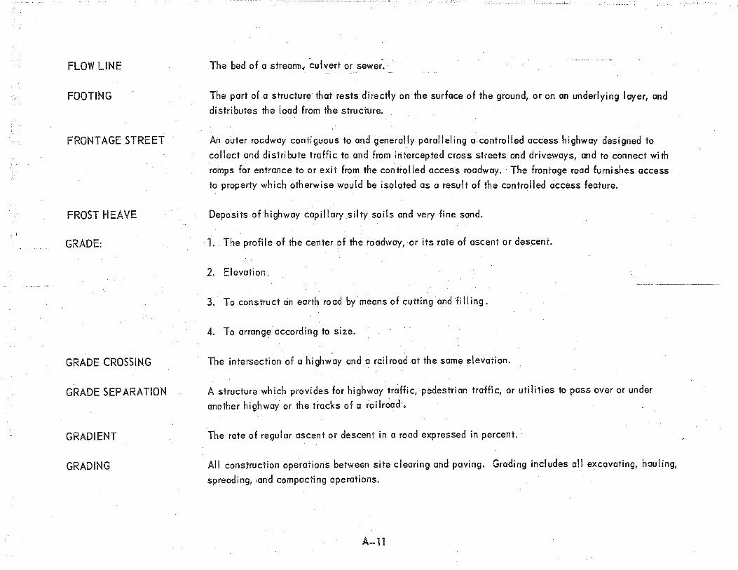
FLOW LINE
FOOTING
FRONT AGE STREET
FROST HEAVE
GRADE:
GRADE CROSSING
GRADE SEPARATION
GRADIENT
GRADING
The bed of q strea1111, culvert or sewe;.
The part of. a structure that rests directly on the surface of the ground, or on an underlying Ioyer, and
distributes the load from the structure.
An outer roadway contiguous to and generally parol! eli ng a. contra lied access highway designed to
collect and distribute traffic to and from intercepted cross streets and driveways, and to connect with
ramps for entrance to or exit from the controlled access roadway. The frontage road furnishes access
to property which otherwise would be isolated as a result of the controlled access feature.
Deposits of highway capillary silty soils and very line sand.
·1 .. The profile of the center of the roadway, or its rate of ascent or descent.
2. Elevation,
3. To construct an earth road by means of cutting and fi II ing.
4. To arrange according to size.
The intersection of a highway anda railroad at the same elevation.
A structure which provides for highway traffic, pedestrian traffic, or utilities to pass over or under
another highway or the.tracks of a railroad·,
The rate of regular ascent or descent in a road expressed in percent.
All construction operations between site clearing and paving. Grading includes all excavating, hauling,
spreading, .and compacting operations.
A-ll

GUARDRAIL
HEADWALL
HIGH EARLY STRENGTH CEMENT
HIGHWAY
HOT MIX
INTERCEPTING DITCH
INVERT
JOINT, CONSTRUCTION
JOINT, CONTRACTION .
JOINT, EXPANSION
JOINT, PLANE OF WEAKNESS
LANE LINE
A protective barrier bui It along the highway shoulder to prevent vehicles from driving down a hazardous
slope or from hitting fixed objects. ·It is also placed in the median to prevent cross-median collisions.
A vertical wall, usually of concrete, at the end of a culvert to prevent earth from spilling into the channel.
Portland cement which is especially prepared to develop strength in a concrete structure in a limited
time (3 to 7 days) -- normal cement usually takes 14 days.
The entire width between the boundary line~ of every way publicly maintained when any part thereof is
open to the use of the public far purposes of vehiculartravel.
A general term used for hot plant-mixed bituminous concrete and sheet asphalt mixtures which are
manufactured and laid at temperatures ranging from 25Qo to 375o F.
A ditch at the top of a slope to prevent surface water from flowing over the slope.
The floor or bottom of a culvert or sewer.
A joint, with or without tie bars and with or without keyways placed in a concrete pavement !o
facilitate construction.
A groove in the concrete surface filled with a premolded or poured filler, usually placed longitudinally,
. to control cracking due to contraction; not a true joint.
A joint, with or without load transfer devices, placed in a concrete pavement to permit expansion.
A groove in the concrete surface filled with a premolded or poured filler, usually placed transversely,
to control crack,'ng due to contraction; not a true joint.
A marked longitudinal line other than the center line separating two traffic Iones.
A-12

LEVELING COURSE
MAXIMUM UNIT WEIGHT
MECHANICAL ANAL YSJS
MEDIAN
MOISTURE CONTENT
NOTICE TO PROCEED
PACKAGE PROJECT
PAVEMENT MARKINGS
The bituminous course constructed immediately on top of the base, ar existing pavement, .for the
purpose of removing sags below a planned grade before an overlying course is placed.· A binder
course may act as a leveling course and may then be called a binder-leveling course.
Maximum unit weight, ·when used as a measure of compaction or density of soils having a loss by
washing greater than 10 percent, shall be understood to mean the maximum unit weight per cubic foot
as determined by AASHTO T 99, Method C, modified to include all material passing the l-inch sieve.
For soi Is having a ·loss by washing of 10 percent or less, the maximum unit weight wi II be determined
by the Method of Test for the Compaction and Density of Soils (Granular) as described in AppendixD
of the Field Manual of Soil Engineering.
The above methods may be modified to allow one sample in conjunction with typical moisture-density
curves developed by the Department ..
The segregation of particles of soil or aggregate, including cloy and si It, by screening into various sizes.
The portion of a divided highway separating the traveled ways.
The percentage, by weight, of water contained in soil or other material usually used on the dry weight.
Written notice to the Contractor to proceed with the contract work including, when applicable, the dote
of beginning of contract time.
A project combining two or more parts, each part consisting of a separate structure or type of construc
tion ·into a single proposal. 1
All lines, patterns, words, colors or other devices, except signs or signals, set into the surface of,
applied upon or attached to the pavement or curbing or to objects within or adjacent to the roadway,
officially placed for the purpose of regulating, warning or guiding traffic.
A-13

PAVEMENT STRUCTURE
PILES
PIPE, CONCRETE
PIPE, CLAY
PIPE, CORRUGATED
PLAN GRADE
PLANS
POINT OF CURVATURE
(P.C.)
POINT ON CURVE
TANGENT (P.O.C.T.)
POINT OF INTER
SECTION (P.L)
POINT OF TANGENCY
(P.T.)
Any combination of subbase, base course, 'and surface course, including shoulders, placed on
a subgrade.
Vertical or nearly vertical members, embedded partly or entirely in the ground, used to provide support
for a structure where the ground is not firm enough.
Modified bell. and spigot pipe made of concrete, plain or reinforced with steel, used forculverts,
sewers, et~. .
Pipe made of shale and fire clay, unglazed, glazed, or glazed and vitrified, ,with or without bell, used
for field drains, edge drains, etc.
Pipe fabricated from corrugated steel sheets used for culverts, downspouts, etc.
Vertical control grade shown on plans.
The approved plans, profiles, ,typical cross sections, applicable standard plans, working drawings and
supplemental drawings, or exact reproductions thereof, which show the location, ,character, dimensions,
and detai Is of the work to be done.
The point where alignment changes from a straight line to a circular curve.
A point on tangent between the point of curvature or the point of tangency and the point of intersection.
(An engineering term)
The point where two tangents or straight lines cross.· (An engineering term)
The point where the alignment changes from a circular curve to a tangent or straight line. (An
engineering term)
A-14
POINT ON TANGENT
(P.O.T.)
PREQUALIFICATION
PROGRESS SCHEDULE
PROJECT
PROJECT LIMITS
PROPOSAL
PROPOSAL GUARANTY
REINFORCED CONCRETE
RETAINING WALL
RIGHT-OF-WAY
RIGID PAVEMENT
A point on the straight line segmenf between any two control points.
The limitations or the process, in accordance with the "Administrative Rules Governing the Pre
qualification of Bidders for Highway Construction Work," by which the Department establishes limita
t.ions on amounts and types of work contractors are permitted to bid on.
A required part of the contract pertaining to the order of proceeding with the various items of the work
to be done and the time schedule for completing said items of work.
The specific section of the highway construction to be performed under the contract.
The limits shown on the plans indicating the beginning and ending of the permanent work included
in the project.
The written offer of the Bidder, on the form furnished, for the work proposed.
The security designated in the proposal and furnished by the Bidder as a guaranty of good faith to enter
into a contract for work proposed. •
Concrete in which steel reinforcement is embedded so that the steel and concrete act together in
resisting stress.
A wall built to hold bock earth or loose rock, so that the material behind the wall will not slide or cave in.
A general term denoting land, property or interest therein acquired for or devgted to a highway, as shown
on the plans.
A pavement which has a high bending resistance and distributes loads to the foundation over a large
area .. An example is portland cement concrete pavements.
A-15
RIP RAP
ROADBED
ROADSIDE
ROADWAY
SCREED
SEAL COAT
-- --- -- - - SHOULDER
SHRINKAGE
SLOPE
SLOPE STAKE
SLUMP
A protective covering of stones, with or without mortar, on an earth bed.
That portion of the roadway between the outside edges of finished shoulders, or the outside edges of
berms, ·back of curbs or gutters, when constructed.
That portion ofthe right-of-way outside of the roadway.
That portion of the right-of-way required for construction, limited by the outside edges of slopes and
including ditches, channels, and all structures pertaining to the work.
Mechanically-operated strike off unit and float for concrete paving operations. ·
A surface treatment, consisting of one or more applications of bituminous material and aggregate passing
the 1/2 inch sieve )00%.
The portion of the roadway contiguous with the traveled way for accommodation of stopped vehicles, for
emergency use, and for I ateral support of base and surface courses. ·
The amount of percent which excavated material diminishes in mass during excavation filling and
compaction.
The lace of an embankment or cut section; any ground whose surface makes an angle with the plane of
the horizon.
Stake set at the point where the finished side slope of an excavation or embankment meets the surface
of the existing ground. :
The difference between the height of the mold (cone) and the height of the vertical axis of the specimen
(fresh concrete) immediately after removal of the mold.: The slump test is used to determine the con
sistency of freshly-mixed concrete.
A-16

SPECIFICATIONS
SPILLWAY
STAGE CONSTRUCTION
STANDARD PLANS
STATE:
STATION
STOCKPILE
A general term applied to all directions, provisions and requirements pertaining to performance of
the work. :
1. ·STANDARD SPECIFICATIONS-All requirements and provisions contained in this document of Standard
Specifications for Highway Construction. ·
2. SUPPLEMENTAL SPECIFICATIONS-Detailed specificqtions supplemental to or superseding the
Standard Specifications.
3. :SPECIAL PROVISIONS -The special requirements, regulations, or directions prepared to cover work
on a particular project not provided by the Standard Specifications or Supplemental Specifications.
An addendum is a Special Provision.··
A surfaced apron for conducting water down a relatively steep slope.
The building of a highway pari at a time such as all earth work one year and surfacing the next year.
Those plans which contain standard details, of contract items and materials, which are in general use.
1. The State of Michigan, •when the Stale is the awarding authority;
2. The County, when a county is the awarding authority;
3. The Municipality, when a city or village is the awarding authority.
A standard of length, usually 100 feet, measured along the centerline of road or along a survey line.
1. Reserve material.
2. To place material, as gravel, in piles at certain locations for use.
A-17

SUBBASE
SUBGRADE
SUBSTRUCTURE
SUPERELEVATION
SUPERSTRUCTURE
SUPPLEMENTAL
SPECIFICATIONS
SURCHARGE
SURFACE COURSE
TANGENT
TEMPORARY ROAD
The layer of specified material of designed thickness placed on the subgrade as a part of the pave
ment structure.
That portion of the earth grade upon which the pavementstructure is to be placed.
All of that part of a structure below the bridge seats or below the skewbacks of arches, including
backwalls designed integrally with the superstructure.
The rise of the outer edge over the inner edge of the road surface at curves, expressed in feet per
foot, for the purpose of counteracting centrifugal force.
All of that part of a structure not classified as substructure.
Detailed specifications, supplemental to or superseding the Standard Specifications.
Excess fill material placed above the final grade line to aid in peat removal by virtue of the
excess weight.
The top layer of a pavement structure.·
A mathematical (or engineering) term generally used to describe a straight line which touches but does
not cross or penetrate a curved line or surface.
A roadway constructed to foci! itate the movement of highway and pedestrian traffic around a construction
operation i ncl udin g appurtenances.
TEMPORARY STRUCTURE A bridge, culvert, or grade separation constructed to maintain traffic during the construction or recon·
struction of a bridge, ·grade separation, or culvert.
TILE EDGE DRAIN A tile pipe I ine constructed off the edge of a pavement to drain the subsoi I.
A-18
TOE
TOPSOIL
TRAFFIC LANE
TRAVELED WAY
TURNING POINT (T.P.)
UNIT PRICE
VOIDS
---- WATER TABLE
WEARING COURSE
WORK
WORKING DAY
WORK ORDER
The bottom edge of a slope
Surface soil.
A strip of roadway intended to accommo.date the forward movement of a single line of moving vehicles.
The portion of the roadway for the movement of vehicles, ·exclusive of shoulders and auxiliary'lanes.
A semi-permanent point used -in leveling on which a foresight is made to establish. its eLevation before
moving the level ahead and alter which a backsight is made to establish a new height of instrument.
The amount of money per single quantity of a specific term of the several items specified in a contract.
The empty spaces between particles in a substance or mixture.
The elevation of the upper limit of the portion of the ground wholly'saturated with water.
· The top crust or surface of a pavement.
Work shall mean the furnishing of all labor, materials, equipment, and other incidentals necessary or
convenient to the successful completion of the project and the carrying out of all the duties and obliga
tions imposed by the contract.
Any day when, as determined by the Engineer, it is possible for the Contractor to effectively carry out
work on the controlling operation.
A written order of contractual status signed by the Engineer and requiring performance by the Contractor.
A-19

APPENDIX B
THE CONSTRUCTION CONTRACT
When you study contract plans in greater detail, you will encounter repeated reference to the construction contract. This chapter
covers how contract plans are developed and the other contract documents needed to build highways and bridges.
PLAN DEVELOPMENT
Planning and designing of a highway employs the skills and services of literally hundreds of engineers, planners, researchers, and
.technicians expert in many fields-engineering, geology, urban planning, electronics, real estate, etc. Preparation and paving of a
highway roadbed, the most visible of a long series of steps involved in highway.construction, ·is also the last operation in a plan that
may have started 15 years earlier, or more.
TRAFFIC AND PLANNING INFORMATION
People and their activities determine the need for new and better roads. The steady growth of population, ·the more rapid increase in
the number of cars and trucks, and the miles that they are driven, 'creole new traffic problems and a demand lor better roads; sa do
the spread of cities. into suburban areas and the building of shopping centers, schools, factories, and other traffic generators.
Long before contract plans are prepared, the Department gathers information on the kinds and amounts of traffic using the roads.
Estimates an;, made on what future traffic will be. This information helps to plan the right kind of roads and guides designers in
determining the standards to be used.
You have often driven over a rubber tube stretched across the pavement and connected to an orange box at the roadside. The box is
a pneumatic traffic counter and it registers the passage of every vehicle over a period of time. The ligures .it collects, together with
those collected by hundreds of other counters, ore translated by traffic engineers into traffic flow maps that show accurately the
number of cars carried daily over slate and county roads.
To' these figures are added accident frequency statistics, the results of special studies of trip origin and destination of cars and
B-L

trucks and detailed maintenance reports indicating the condition of the existing highways. Otherstudies are concerned with popu
otion growth, economic development of certain areas of the state and many other trends. Together, ·this data enables highway
engineers to predict traffic densities.·
By correlating studies and observations with a detailed inventory of all state and county roads, highway engineers are able to give
everymile of highway a "sufficiency rating" that indicates its traffic capacity. The ratings range between 0 and'lOO, ·100
being perfect.
When a sufficiency'rating begins to drop, engine~rs list that section of highway as critical and begin more studies to detennine
what treatment will be necessary to restore it. These show whether widening will be sufficient, whether extra lanes should be add
ed, or whether the road should be entirely rebuilt or relocated.
ROUTE LOCATION
Again it is people and their activities who determine the routes of new highways.·
Highway planning requires the cooperative efforts of many groups. Officials of the Department are continually in contact with
officials of villages, towns, cities, and county governments. who know local needs and problems.
Federal law requires the preparation of highly detailed studies of the social, economic, and environmental effects likely to result
from construction of proposed highways. Working with other state agencies, Department,expertsiin such varied fields as biology,
geology, and urban planning calculate the effect of proposed construction on public recreation land, wildlife habitat, land use,
and other social and environmental situations. These are all weighed carefully in selection of a highway route.
DESIGN SURVEYS
In surveying route locations, the Department tries as far as possible to avoid or minimize interference with water supplies, sewer
systems, airports, parks, cemeteries, ·industrial plants, ond major public developments of all kinds. Neighborhood boundaries also
are considered.
With the help of aerial and ground surveys, planners and engineers lay out proposed routes. Ideally, ·the route selected is the most
direct and least expensive to build. But the shortest route may not be the best one. The highway must skirt lakes and swamps,
B-2

engineers try to avoid hills, ravines, rock outcrappings, and other physical barriers. In developed areas, the shortest route might
require the removal of most buildings, or have the most damaging effect on commerce and community life.
Final selection of a route is made by the State Highway Commission, with approval of the Federal Highway Administration if federal
aid is involved.
Opinions of the public at large ore actively sought from the beginning of the planning process. With each proposed project, ad
ministr(llors and planners weigh every alternative, ,including the potential effects of doing nothing at all.
If construction is warranted, preliminary studies are undertaken by Department engineers and other professionals. Then public hearings
are scheduled so the homeowner, the businessman, and any other interested citizen may voice his opinion. The first hearing is for dis
cussion of alternate highway corridors, ,each from one to three miles wide. Later, after the route is approved by various state and
federal authorities, a second hearing is held on the design features of the highway-location of interchanges, ·for example, if it is to
be a freeway.
When it has been decided to build a certain highway, His necessary to perform a field survey to gather information needed by the design
engineers. The survey establishes the hi9hway location and records precise measurement of distances, elevations, topographic features
such as buildings, fences telephone poles, drainage areas, and many other features that wi II be important to the design of the highway.
PROJECT DESIGN
In the Design Office, the survey information is compiled and designs are developed for building the new rood or bridge. Decisions are
made about the shape of the road-width, elevations, grades, ditches, intersections, and sometimes very complicated interchanges.
Decisions are made about drainage-size of cui verts and how best to take care of surface water. Decisions are made about the strength
of the road-the types of soils used and the types and amounts of surfacing materials. These and other decisions establish a design
for the highway which is most effective and most economical.
CONTRACT DOCUMENTS
CONTRACT PLANS
In order for contractors and Department project engineers, ,construction surveyors and inspectors to know how the road or bridge is to
be built, it is necessary for the design decisions to ·be put down on paper in the form of illustrative drawings, notes, and instructions-
B-3

-- ihe contract plans. In addition to showing how the project is to be built, ·the contract plans shown an estimate of the amount of work
to be done-cubic yards of earth to be moved, tons of surfacing materials, linear feet of drainage pipe, etc. This serves as a basis
for estimating the cost of the work and for paying the contractor for work performed.
Contract -pi ans are one oTthe most imporfant contract documents usedby-proj ect engineers~ instrumentmen, and inspectors. The
meaning and intent of the plans must be thoroughly understood.
CONTRACT PROPOSAL
The contract proposal is the written offer of the bidder, on the form furnished by'the Michigan Department of State Highways and
Transportation, for the workproposed. Prequalified bidders are furnished with proposal fo.rms which will state the location and des
cription of the work contemplated, the approximate quantities of the work to be performed and materials to be furnished, the amount of
the proposal guaranty, and the date, time and place of filing and opening proposals. The proposal will also include any special
provisions or requirements which vary from or are not contained in the Standard Specifications·, or on the plans.
The proposals received are compared on the basis of the summation of the products of the quantities of items listed and the unit prices
bid. After checking all bids, the low bid is made public.
Acceptance of the proposal of the lowest bidder, and the rejection of the other proposals, is made by the Highway Commission as
soon as practicable. The project is then deemed awarded and a binding contract shall arise only when the contract form has been fully executed by both the determined lowest bidder and the Commission.
STANDARD SPECIFICATIONS
The book "Standard Specifications for Highway'Construction" of the Michigan Department of State Highways and Transportation sets
forth the directions, provisions, ·and requirements that apply to all contractors on all road projects.
1. Legal requirements for bidding and for performing the work.
2. Construction details about how work should be done.
3. Specifications for materials and criteria for testing materials.
B-4

4. Methods of measurement and basis of payment lor work performed.
SUPPLEMENTAL SPECIFICATIONS
Sometimes it is necessary to revise the Standard Specifications, hut it is not cqnvenient or practical to publish a new specification
book each time a change occurs. To take care of this situation, Supplemental_ Specifications are written and included separately
with each project contract proposal. These supersede the Standard Specifications and ore used on each project until they can be
included in a new revision of the book of Standard Specifications.
SPECIAL PROVISIONS
Frequently some unusual problems or conditions are found when designing a project, ·and special instructions are needed. For this
situation, Special Provisions are written which apply only to a particular project. These supersede both the Standard Specifications
and Supplemental Specifications ifthere happen to be any discrepancies.
DISCREPANCIES
In case. there ore discrepancies between the contract plans and the various sources of specifications, the Special Provisions are the
highest level of authority, followed, in descending level of authority, by the contract plans, the Supplemental Specifications and, last
the Standard Specifications.
B-5

APPENDIX C
RIGHT-OF-WAY
Right-of-Way'(R.(il.W.): is the land, property, or interest acquired for the construction of a highway. The width of the R.O.W. must
provide sufficient room for pavement, ,shoulders, ditches, ,slopes, miscellaneous structures, ,and clear vision areas.
R.O.W. needs are detenmined by the Design Division and are acquired by the Right-of-Way Division. It is essential that the Right-of
way chosen shall meet all the requirements ofultimate construction as detenmined by orderly highway planning.
In general, R.O. W. widths for different types of construction are shown in the "Plan on File of Proposed Right-of-Way Widths.'_' The
R.O. W. widths shown are considered as the operational R.O. W. requirements by the Department and are used as a guide. Anticipated
traffic volumes, stage construction, real estate values,
selection of right-of-way widths.
RIGH'F-OF-WAY PLANS
winter snow removal, flat or rolling country, etc., ,are considered in the
A separate set of plans is required to cover right of way details. The purpose of these plans is to furnish the Right-of-Way Division 1
with plans that have the right-of-way requirements outlined in sufficient detail so that the proper descriptions con be prepared and
land acquired for construction purposes. The information on the plans is used in drawing up various instruments such as deeds, re
leases, easements, etc., ,and in legally describing and locating the various parcels of land referred to in these instruments. Right
of-way plans are also used for court actions and for record purposes.
Right-of-way plans are a plane graphical representation of the areas and rights required for the construction and operation of the
proposed improvement superimposed upon a map of the properties affected.
In order to arrive at an estimate of the amount of money ta be paid to an owner for his land and rights needed for the highway, on
appraiser must be able to determine from the plans, all items of value to be taken and the effect of the taking on the value of any
remaining property.
_ C-1•

Acquisition of property requires the execution of on instrument of conveyance which includes a legal description of the land needed.
The plans show all. information necessary for preparing the required legal description.
During the negotiations, .the Right-ofcWay Agent must be able to explain what the take is intended to be. Without the proper plans,
on understanding of what the plans represent, and the ability to convey to the owner what he needs and desires to know, the negotia
tions would be most difficult.
After the right-of-way has been acquired, the plans represent a record of what was purchased. This record ·will support the State's
claim reimbursement in the case of a federally funded project. It will also serve as a reference for surveyors, ·O base for future
projects, ·and on inventory of.the Department's right-of-way.
PREPARATION OF RIGHT-OF-WAY PLANS
The bose R.O.W. tracings ore prepared by the Design Division and are mode from the construction plans after the·design survey
has been plotted. They will show all section and quarter corners and witnesses with ties to the survey centerline. Where the con·
structioR--centerline varies from the survey centerline, the land tie data must be computed to the construction centerline. Slope
stoke lines ore also shown.
At this stage, the right-of-way plans differ from the construction plans in the following respects:
1. The axis of the roadway is centered on the plan sheet.
2. Cross roods, se.ction lines, etc., ore extended to utilize the full width of the sheet.
3. Profiles ore on separate sheets at the end of the sequence of plan sheets.
WORK PERFORMED BY R.O.W. DIVISION
Next, the plans are transmitted to the Right..ofcWay Division for additional right-of-way information. Here, the total contiguous
ownerships of all properties affected by the proposed right-of-way ore ascertained and plotted on the tracings as given in their
title searches.
C-2

Ownership descriptions containing definite distances are indicated on the plans and each ownership on the project is given a parcel
number. The parcel is show~ on the plans by placing a number in a small rectangular box. Parcel numbers are assigned numerically
from beginning to end of the project.
Each project is provided with an ownership sheet. This sheet will show the parcel number, name of ownership, ·total area of the
property, the amount of right-of-way 'being taken in fee, easement, permit, etc., and the areas of the remainders of said ownership.
This is a separate sheet and is usually inserted in the plans between the title sheet and the point of beginning of the project.
FINAL RIGHT-OF-WAY PLANS
After Right-of-Way has completed its required work, the tracings are returned to Design for completion. The final right-of-way plans
· are then prepared and the final right-of-way is plotted on the construction plans. Final right-of-way plans are separate from construc
tion plans and are not included in the bidding plans; however, they ore furnished to the District Office.
REVISED RIGHT-OF-WAY
Changes in right-of-way, nfter it has been submitted, are held to a minimum. Those changes necessitate additional time for the Right- - - -~
of-Way Division to clear all requirements so there will be no interference or delay in construction operations. However, there are
instances when, because of unforeseen conditions such as additional data being received from the field, ·difficulty encountered in
negotiating with a property owner, necessity for submitting right-of-way plans before final plans have been completed and checked,
etc., that revised right-of-way is unavoidable.
CONSTRUCTION RIGHT-OF-WAY
Survey crews are frequently required to stake out right of way at interchange areas. R.O. W. plans in these areas usually show a series
of chords with bearings and distances which are tied into the survey centerline of freeway or ramp~
All right-of-way lines not parallel to the project centerline or cross road centerline are identified by bearing and distance, ·station, and
offset distance to construction centerline, or distance along lot lines.
Sometimes the above mentioned R.O.W. ties are not on the construction plans. If not, ·this information can be obtained by calling the
Design Division Squad Leader who designed the project and requesting the right-of-way plans or having him compute the required
ties using the computer. Remelllber,'.this information is available if needed.
C-3 r

It is important to keep in mind that even though the right-of-way plans themselves may be separated from the rest of the plans far
specific purposes, ·they are an integral part of the total plans. For righJ-of~way purposes, neither the right·of-way plans nor the
construction plans can stand alone. Many items of vital concern to construction people need not show on the right-of-way plans.
Conversely, the construction plans do not show some of the specific items required on the right-of-way plans. In many instances,
however, the complete plan must be studied in order to answer any given question.
C-4