Embed Size (px)
Citation preview

IEEE TRANSACTIONS ON COMMUNICATIONS, VOL. 64, NO. 1, JANUARY 2016 59
RS-LDPC Concatenated Coding for the ModernTape Storage Channel
Jieun Oh, Jeongseok Ha, Member, IEEE, Hyegyeong Park, Student Member, IEEE,and Jaekyun Moon, Fellow, IEEE
Abstract—In modern tape storage, user data are recorded andretrieved along multiple tracks of rapidly moving, flexible mag-netic medium that give rise to a variety of channel impedimentsincluding occasional long erasures, more frequent amplitude fadesas well as a large amount of random errors. This work considersreliable recovery of data from such tape channels using a novelconcatenation of an inner Reed-Solomon (RS) code and an outernonbinary low-density parity-check (LDPC) code. This particu-lar concatenation scheme and a highly tailored iterative decodingalgorithm are chosen to efficiently handle the assortment of thetape channel impediments while meeting the stringent target errorrate constraint as well as key practical requirements of the masstape storage system. Despite the use of a nonbinary LDPC code,the proposed scheme allows excellent performance-complexitytradeoffs. In stark contrast to any existing coding schemes thatinvolve LDPC codes, the proposed concatenation strategy allowssemianalytic error rate performance evaluation at rates belowwhat is possible using modern computers, thus providing an abilityto ensure satisfactory low-error-rate performance.
Index Terms—Channel coding, error correction codes, taperecording.
I. INTRODUCTION AND MOTIVATION
T HE ADVENT of social networking coupled with theemergence of the Internet of Things fuels exponential
growth in user data, which leads to huge demands on data stor-age. Among various types of mass storage devices, tape storagecontinues to be a viable choice for backing-up and archivingmassive amounts of data [1] due to its notable advantages incapacity, cost, endurance and power consumption. While tapestorage has continuously evolved in the direction of provid-ing higher and higher bit densities over the past few decades,the ever-increasing demand for storage capacity calls for anaccelerated effort in the same direction. Such efforts, unfortu-nately, always face serious challenges in maintaining the dataintegrity. In particular, the bit density improvement in mod-ern tape systems has been mainly driven by increase in track
Manuscript received May 20, 2015; revised October 7, 2015; acceptedNovember 19, 2015. Date of publication November 30, 2015; date of currentversion January 14, 2016. This work has been supported in part by theTape Program in Information Storage Industry Consortium, the NationalResearch Foundation of Korea (NRF) Grants (No. 2010-0029205 and No.2015R1A2A2A01007739) funded by the Korea Government (MISP), and theBK21 Plus. The associate editor coordinating the review of this paper andapproving it for publication was D. Declercq.
The authors are with the Department of Electrical Engineering KoreaAdvanced Institute of Science and Technology, Daejeon 305-701, SouthKorea (e-mail:[email protected]; [email protected]; [email protected];[email protected]).
Digital Object Identifier 10.1109/TCOMM.2015.2504362
density, which has resulted in an inevitable deterioration of datareliability [2]–[4].
Data reliability in storage systems is usually guaranteedby employing error-control codes which should be carefullydesigned to handle error characteristics specific to the tar-get storage channel. The tape storage channel is marred by acombination of impediments including broad-band noise, shortfades, and long erasure dropouts due to a variety of materialand mechanical imperfections such as media noise, thermalasperities, head-medium space variations, media defects andsynchronization losses [5], [6]. In what is called the lineartape-open (LTO) standard [5]–[8], an error-control system witha RS-based two-dimensional product code and hard-decisiondecoding is employed for handling tape-specific errors. The RSproduct code, called RS-RS concatenation hereafter, is knownto provide a very strong error-correcting capability in the pres-ence of the characteristic long dropouts while offering fairlyrobust protection against random errors at a reasonable com-plexity level. Moreover, the RS-RS scheme is designed tosupport an important tape-specific requirement, namely, read-after-write verification for enabling tape systems to read andvalidate data immediately after they are written. This preventsthe system from storing data on highly unreliable, defect areasof the tape.
While error-control using the above-mentioned RS-RS con-catenation is widely deployed in current tape systems, asthe track density gets higher, the signal-to-noise ratio (SNR)decreases proportionally to a point where the RS-RS con-catenation is no longer able to protect data. Thus, a strongererror-control system well-tailored to tape medium is criticalfor developing next-generation tape storage. To this end, therehave been some notable research works [9]–[14], where LDPCcodes were considered for improved error control. In [9], per-formance of LDPC codes was investigated on real data taken offhigh-density metal particle media. The study in [9] concludedthat LDPC codes were appropriate for tape recording systemsin which the per-channel data rate requirement is significantlylower than that of hard disk drives. Meanwhile, in [10], [11],the outer RS code in the RS-RS concatenation were replacedwith a packet LDPC code. In these works, the inner RS decoderconverts a tape channel into an erasure channel by marking thesymbols of failed codewords as erasures. While packet LDPCcodes with the erasure filling decoder provide outstanding per-formance, the scheme does not always take full advantage ofreceived signals from the tape channel since the symbols in thefailed inner RS codewords are treated as erasures.
0090-6778 © 2015 IEEE. Personal use is permitted, but republication/redistribution requires IEEE permission.See http://www.ieee.org/publications_standards/publications/rights/index.html for more information.

60 IEEE TRANSACTIONS ON COMMUNICATIONS, VOL. 64, NO. 1, JANUARY 2016
The noisy channel of the future tape media will be in amuch lower SNR regime than that of today’s tape drives [1].Thus, it would make sense to develop error control systemsthat utilize soft information from the channel while also pos-sessing strong burst error correction capability. In addition, theread-after-write verification feature must be supported.
To meet the above requirements, we consider an error-controlsystem in which the outer RS code in the existing RS-RS con-catenation code is replaced with a non-binary LDPC code andan iterative decoding scheme between the inner and outer codesis employed. The proposed coding scheme will be called RS-LDPC concatenation in the sequel. It should be noted that whilealgebraic codes are often chosen as outer codes [15], [16], inthe proposed RS-LDPC concatenation, we deliberately chooseRS codes as the inner code for the following reasons: 1) theinner RS code makes implementation of read-after-write ver-ification straightforward via on-the-fly decoding of the innercode and 2) decoding complexity for a non-binary LDPC codecan be significantly reduced when the outer decoder takes thehard decisions of the inner RS decoder as inputs. Meanwhile,the outer LDPC codes over higher-order Galois fields may beable to provide a large coding gain even for moderate codewordlengths [17], [18] as well as providing a more natural fit forthe given inner-outer code concatenation since the inner code isnon-binary as well.
In the proposed error-control system, the inner RS decoderconducts traditional hard-decision decoding. The outer LDPCdecoder either takes the hard symbol decisions out of the RSdecoder as clean symbols or, when the RS decoder fails, usessoft information from the channel. The LDPC decoder outputsare fed back to the RS decoder which retries decoding on thecodewords that failed in the first place. The decoding for theouter LDPC codes is subsequently done. The process continuesin this fashion until either the LDPC decoder generates validcodewords for the entire user data or enough attempts have beenmade. In the iterative decoding, the complexity of soft-decodingfor the non-binary LDPC codes becomes manageable as theinner RS decoder makes clean hard decisions most of the times,which has an effect of removing the majority of the edges in thefactor graph representation of the LDPC code. The combinationof RS-LDPC concatenation and soft-decision decoding for theouter LDPC codes is already studied in [19] in an effort to com-bat the effect of impulsive noise in power-line-communicationschannel. However, the work in [19] adopts binary LDPC codesas outer codes.
The present work is different from the previous works [10],[11], [19] in that our decoder improves performance over itera-tions between inner and outer codes, whereas none of [10], [11],[19] employs inner-outer iteration. The selective use of eitherhard decisions out of the inner RS decoder or the soft channelequalizer outputs as the inputs of the outer decoder is also aunique feature of our work. The utilization of hard RS decoderoutputs during the vast majority of time is what allows thepractical deployment of the usually very-complex non-binaryLDPC code, which is in contrast with the works of [10], [11],[19], all based on binary LDPC codes. In addition, for thepacket-LDPC codes in [10], [11], performance evaluations arecarried out only in limited cases. On the contrary, we evaluate
performances of the proposed error-control scheme under var-ious channel conditions - intersymbol interference, long andshort dropouts/fades, random errors - representing realistic tapestorage systems. More importantly, in the previous works [10],[11], [19], performance evaluations are carried out with com-puter simulations. However, the target error-rates of storagesystems are set too low to be evaluated with computer simula-tions. As is well known, for any coding scheme involving LDPCcodes, performance evaluation in the low-error rate regime,where trapping sets limit the performance potential, is an openproblem [20]. While many researchers have attempted to solvethe error floor problem caused by the trapping sets by modi-fying LDPC encoders [21]–[27] or by proposing decoder-basedstrategies [28]–[30], the challenge of lowering error floors with-out increasing the encoder/decoder complexity or decodinglatency remains high. Accordingly, the performance of the cod-ing methods proposed in [10], [11], [19] could not be validatedin the low-error rate regime where the performance targets ofpractical storage system are actually set. In contrast, we showthat the specific structure of our concatenation coupled with thesuggested decoding iteration method allows computation of theerror rate upper-bound in the extremely low error rate regime,thus ensuring the satisfactory low-error-rate performance of theproposed error control scheme. Our analysis is based on esti-mating the probabilities of the occurrences for the particularstopping sets at the RS decoder output, which are known to failthe given outer LDPC code.
The rest of the paper is organized as follows. Section IIpresents the model of magnetic tape storage when viewed asa type of communication channel based on the input sym-bols, channel noise/disturbances and observed channel outputs.This section also provides an overview of the conventionalRS-RS concatenation coding scheme in the specific LTO-5standard. Section III gives a detailed description of the proposederror control scheme. The semi-analytic method for estimatingsymbol-error rate (SER) in the low SER regime is presented inSection IV. In Section V, comprehensive performance evalua-tions of the proposed and conventional schemes are carried outunder different channels conditions. Finally, in Section VI, weconclude the present work.
II. TAPE SYSTEM
A. Error-Control System in LTO-5
In the new LTO-5 standard, the encoding operation starts byhierarchically dividing a chunk of user data called data set. Thefirst level of partitioning gives rise to a number of sub datasets. Each sub data set is further divided into four quarter subdata sets. Each quarter sub data set is independently encodedinto codewords of the RS-RS concatenation. Thus, the quartersub data set is a basic data unit of the encoding operation. InFig. 1, the quarter sub data sets are denoted by Qi for 0 ≤ i ≤ 3,respectively.
The RS-RS concatenation is also illustrated in Fig. 1 wheretwo RS codes denoted by C1 and C2 are block-concatenatedin the row and column directions, respectively. The outer codeC2 is a [n2, k2] = [96, 84] code whereas the inner code C1 is

OH et al.: RS-LDPC CONCATENATED CODING FOR THE MODERN TAPE STORAGE CHANNEL 61
Fig. 1. The error-control system in the LTO-5 standard.
a [n1, k1] = [240, 230] code. Both are shortened RS codes onGF(28). More specifically, a message block of 84 bytes froma quarter sub data set is encoded into a C2 codeword of 96symbols (bytes) forming a column. After 230 such columns areconstructed, each row gets encoded into a C1 codeword of 240symbols, eventually creating a 96 by 240 symbol array for eachquarter sub data set.
As an extra level of interleaving, four C1 codewords takenfrom the same row positions of the four quarter sub data setsare interleaved symbol-wise before written onto a given physi-cal tape track. This depth-4 interleaving forces the error burstsrunning over several hundred bytes to spread out to multiplequarter sub data sets.
Such four C1 codewords taken from the same row positionsof a sub data set form a unit called a data packet, and thereexist another deeper level of interleaving that spreads out thesedata packets over widely varying locations of the physical tapemedia [8]. This layer of interleaving is required to prevent verylarge error bursts due to media defects/scratches, malfunction-ing header, and/or loss of synchronization from wiping out theentire sub data set.
These two layers of interleaving make the codewords ineach quarter sub data set encounter independent tape chan-nels, which enables us to conduct performance evaluations byinvestigating coding schemes and tape channels specific to thequarter sub data sets. In the sequel we shall focus on a sin-gle quarter sub data set. The overall code rate of the serialconcatenation is simply given by R = R1 × R2 = 0.84 whereR1 = 230/240 and R2 = 84/96.
The inner decoder for C1 is effective at correcting errors dueto short fades and thermal noise. However, long bursts mayoccasionally wipe out entire rows of the quarter sub data set,resulting in the failures of one or more C1 codewords. In suchcases, the message part of the failed C1 codewords will befed to the C2 outer decoder as erasures. Subsequently, the C2decoder sees an erasure channel and conducts erasure decoding.Since the rows of the coded sub data set, i.e. the data packets,are widely dispersed across tape medium, the number of era-sures presented in a C2 codeword is typically within the error
Fig. 2. An equivalent tape channel model.
correcting capability of the C2 code. Thus, the RS-RS con-catenation with multiple levels of interleaving is designed tosimultaneously correct both frequent errors of short/moderatelengths and relatively rare long error bursts. In addition, dur-ing writing the C1 codewords written on the tape track areimmediately read and decoded to verify that no tape defectsare contaminating the written data. If C1 decoding fails duringthis read-while-write verification stage, the failed codewordsget rewritten in a different location of the tape track.
B. Channel Model
The sequence of storing and retrieving coded data in and outof the magnetic tape medium can be modeled as data trans-missions over a noisy communication channel with fades anderasures. As mentioned earlier, the codeword for each quartersub data set encounters an independent tape channel. An equiv-alent tape channel is shown in Fig. 2 where the non-binarycodeword c gets first converted to a bipolar symbol vectorx, a binary-phase-shift-keying (BPSK) representation of thecodeword, which acts as the input to the tape channel. The chan-nel itself is modeled by the extended class-4 partial response(EPR4) [31] with a system impulse response polynomial
h(D) =L∑
�=0
h�D� = 1 + D − D2 − D3 (1)
where D denotes unit delay. In addition to the usual additivewhite Gaussian noise (AWGN), the channel output suffers fromrelatively short amplitude fades and occasional long dropoutsthat are modeled as erasures. Specifically, the channel outputobserved at time i corresponding to the input x is given by
ri = βi
[αi
L∑�=0
h�xi−� + ni
](2)
where αi ∈ R+ and βi ∈ {0, 1} are gains corresponding to the
short amplitude fade and long dropouts, respectively, xi is theelement of x, and ni is the AWGN sample. It is assumed thatthe amplitude and inter-arrival time of the short fades followexponential distributions with averages of λ−1
d and λ−1i , respec-
tively [32] and their durations (intervals over which successive

62 IEEE TRANSACTIONS ON COMMUNICATIONS, VOL. 64, NO. 1, JANUARY 2016
αi ’s take non-zero values) are distributed uniformly over a timerange corresponding to ten to twenty RS symbols. It is alsoassumed that the locations of erasures and channel state infor-mation (CSI) for the short fades, i.e. βi and αi are knownto the detector. Due to interleaving, we can assume that thelong dropouts wipe out each C1 codeword independently withsome probability Pr[βi = 0] = Pβ for each quater sub data set.During the performance evaluation where we do not considerlong dropouts, we simply set Pβ = 0.
The channel detector, typically implemented as a Viterbidetector, releases hard decisions in the existing LTO system.But in the proposed error control system soft channel decisionswill be assumed available via the Bahl-Cocke-Jelinek-Raviv(BCJR) [33] or soft-output Viterbi algorithm (SOVA) [34]equalizer. As the code employed is non-binary, soft decisionscorresponding to the non-binary symbols must be generated.This can be done either by altering the channel trellis for thedirect release of non-binary soft symbol decisions [35] or byconverting the binary-level soft decisions to non-binary softdecisions [36].
III. THE PROPOSED ERROR-CONTROL SYSTEM
This section introduces the proposed error-control systemwhich consists of an outer non-binary LDPC code and an innerRS code. It will be shown that despite the use of a non-binaryLDPC code, this particular concatenation does not increase theoverall complexity significantly while offering substantial per-formance advantages. An important additional merit is that theproposed concatenated code, unlike any coding scheme that uti-lizes an LDPC code, allows estimating error rate performancein the low error rate regime.
In the proposed RS-LDPC concatenation, the inner RS codesis the same as that of LTO-5 whereas the proposed RS-LDPCconcatenation replaces the outer RS code in LTO-5 with a non-binary LDPC code over GF(24). A pseudo-random interleaverof quarter sub data set size is assumed between the inner RSand outer LDPC codes, which allows RS coded symbols to berandomly distributed across NLDPC codewords as illustrated inFig. 3. In the encoding of the outer LDPC code, a quarter subdata set of user data are encoded into NLDPC = 23 outer LDPCcodewords of length n2 = 1, 920 symbols (= 960 bytes) each.Here, the field size of the non-binary LDPC code, GF(24), iscarefully selected for a reasonable compromise between com-plexity and performance. It should be noted that the choice ofan outer LDPC code is advantageous over the conventional RScode in the sense that LDPC codes can be designed at longercodeword lengths without requiring larger finite fields, and thechoice of longer LDPC codes may allow performance improve-ments at a linear-time growth of complexity. Note that we arenot claiming that the proposed RS-LDPC concatenation is eas-ier to implement than the existing RS-RS scheme. Our positionis that the new RS-LDPC concatenation gives an opportu-nity to improve overall performance at the cost of increasedcomplexity relative to the conventional RS-RS concatenation.
Since the inner and outer codes are defined over differentfields in the proposed coding scheme, we treat byte symbols inand out of the outer code as groups of two consecutive four-bitsymbols in an LDPC codeword as one can see in Fig. 3. That
Fig. 3. A block diagram illustrating how the inner RS symbols are spread tothe outer LDPC codewords through a pseudo-random interleaver.
Fig. 4. Decoder block diagram for the proposed concatenated code.
is, a byte of user data amounts to two consecutive messagesymbols in the outer code, and blocks of two adjacent codedsymbols of the outer code are fed to the inner code as mes-sage bytes. The grouping of two coded symbols is intendedto minimize the number of erroneous message bytes due to afailed LDPC code. Without the grouping, a group of two four-bit symbols from a failed LDPC codeword may result in twobad message bytes of the inner RS code.
In the proposed error-control system, we assume an iterativedecoding strategy shown in Fig. 4. The inner RS decoder con-ducts traditional hard-decision decoding. Then, the decoders forthe outer LDPC codes take the hard symbol decisions from thesuccessfully decoded RS codewords as clean symbols throughthe pseudo-random interleaver, as shown in Fig. 3. Meanwhile,for the failed RS codewords, the decoders for the outer LDPCcodes fetch the soft outputs from the channel detector. Inthis work, we assume the log-domain sum-product algorithm(log-SPA) over GF(24) [18] for decoding outer LDPC codes.In doing so, the message updating for the edges with cleansymbols are simply dropped. Subsequently, the hard-decisionoutputs from the LDPC decoder are fed back to the RS decoderwhich retries decoding on the failed codewords in the earlierRS decoding. The iterations of decoding for the inner and outercodes continue in this fashion until either the LDPC decodergenerates valid codewords for the entire sub data set or thenumber of iterations reaches a preset value. Under reasonablechannel conditions, the LDPC decoder takes soft symbol deci-sions only occasionally; most of times its inputs will be cleanhard decisions out of the inner RS decoder. This reduces thecomplexity of the non-binary LDPC decoder tremendously. Inaddition, decoding for the outer LDPC code reveals locationsof clean symbols to the RS decoder, which may also sim-plify the Chien search and syndrome computation steps in RSdecoding. The signal path denoted by the dotted lines representdata flows in the iterative decoding, while the solid lines are
OH et al.: RS-LDPC CONCATENATED CODING FOR THE MODERN TAPE STORAGE CHANNEL 63
in common with the single-pass decoding for the conventionalcoding scheme in LTO-5.
As the inner RS decoder makes clean hard decisions most ofthe times, the majority of the edges in the factor graph repre-sentation of the LDPC code are effectively removed. Since thecomplexity level of the SPA [17], [18] is directly proportionalto the number of edges, the LDPC decoder complexity becomesmanageable in the particular proposed concatenation structure.According to the results in [18], the average number of mes-sage additions in the variable node update for each iteration isgiven by
uM(t − 1)(q − 1)
where q is the field size of the non-binary LDPC code, M is thenumber of check nodes, and t and u represent the mean valuesof variable node and check node degrees, respectively. Whenthe decoder failure rate of the RS inner code is given by φ, theeffective number of edges gets reduced to uMφ, and thus thenumber of additions turns out to be
uMφ(t − 1)(q − 1).
Similarly, the numbers of additions and max∗ [18] operationsin the check node update also reduce to
2(3uφ − 4)M(q − 1)2
from 2(3u − 4)M(q − 1)2. The effective number of edges isfurther reduced as the iteration between the decodings for theinner and outer codes continues. It should be noted that instorage applications, the operating SNR is in general higherto achieve a very low target SER than those in other appli-cations, e.g. wireless communication. Thus, the failure rateof the inner RS code, φ may be much smaller, which makesthe decoding for the outer LDPC code particularly efficientcomputationally.
It should also be noted that performance of the proposederror-control system can be further improved by introducingiterations between the channel detector and decoders. However,this extension will significantly increase latency and com-plexity while also rendering the performance analysis highlyintractable. We will thus not consider this extension in thepresent work.
IV. LOWER-RATE PERFORMANCE ANALYSIS
In this section, we develop a performance evaluation tech-nique for the proposed error-control system in the low SERregime. Again, the proposed system consists of the inner RSand outer LDPC codes, and inner/outer global iteration (IOI) ispossible between the corresponding decoders. The challenge inevaluating performance of the proposed scheme lies in theoret-ical performance analysis of LDPC codes. Error rate evaluationfor LDPC codes is largely an open problem and resort is typ-ically made to computer simulation, which in our case is notfeasible due to the extremely low target symbol (byte) error rateof 10−19 [6]. To resolve this technical challenge, we consideran iterative decoding strategy in Fig. 5 which is sub-optimal
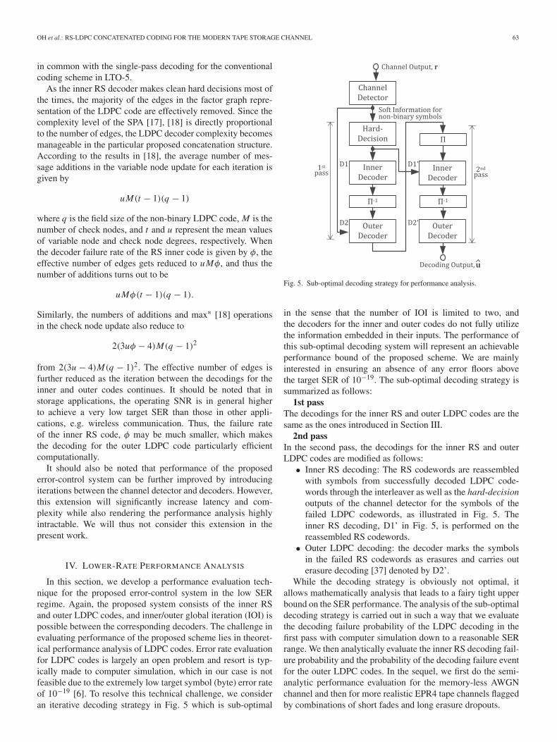
Fig. 5. Sub-optimal decoding strategy for performance analysis.
in the sense that the number of IOI is limited to two, andthe decoders for the inner and outer codes do not fully utilizethe information embedded in their inputs. The performance ofthis sub-optimal decoding system will represent an achievableperformance bound of the proposed scheme. We are mainlyinterested in ensuring an absence of any error floors abovethe target SER of 10−19. The sub-optimal decoding strategy issummarized as follows:
1st passThe decodings for the inner RS and outer LDPC codes are thesame as the ones introduced in Section III.
2nd passIn the second pass, the decodings for the inner RS and outerLDPC codes are modified as follows:
• Inner RS decoding: The RS codewords are reassembledwith symbols from successfully decoded LDPC code-words through the interleaver as well as the hard-decisionoutputs of the channel detector for the symbols of thefailed LDPC codewords, as illustrated in Fig. 5. Theinner RS decoding, D1’ in Fig. 5, is performed on thereassembled RS codewords.
• Outer LDPC decoding: the decoder marks the symbolsin the failed RS codewords as erasures and carries outerasure decoding [37] denoted by D2’.
While the decoding strategy is obviously not optimal, itallows mathematically analysis that leads to a fairy tight upperbound on the SER performance. The analysis of the sub-optimaldecoding strategy is carried out in such a way that we evaluatethe decoding failure probability of the LDPC decoding in thefirst pass with computer simulation down to a reasonable SERrange. We then analytically evaluate the inner RS decoding fail-ure probability and the probability of the decoding failure eventfor the outer LDPC codes. In the sequel, we first do the semi-analytic performance evaluation for the memory-less AWGNchannel and then for more realistic EPR4 tape channels flaggedby combinations of short fades and long erasure dropouts.

64 IEEE TRANSACTIONS ON COMMUNICATIONS, VOL. 64, NO. 1, JANUARY 2016
A. Analysis for the AWGN Channel
Since we have the probability of the decoding failure eventfor the outer LDPC code from simulations, the analysis startswith the decoding for the inner RS code in the second pass.Assuming that there are NLDPC LDPC codewords within a quar-ter sub data set, the decoding failure rate for the inner RS codein the second pass is given by
Pr(
DF(2)RS
)=
NLDPC∑i=1
Pr(
F (1)LDPC = i
)Pr
(DF(2)
RS
∣∣∣F (1)LDPC = i
)(3)
where F (1)LDPC is the number of failed LDPC codewords in
the first pass, DF(2)RS indicates the decoding failure event of
the inner RS code in the second pass. The assumption of anAWGN channel enables us to model the probability of i failedLDPC codewords as a binomial distribution even with a simpleblock interleaver between the inner and outer codes. Thus, thedecoding failure rate for the inner RS code can be expressed as
Pr(
F (1)LDPC = i
)=
(NLDPC
i
) (Pr
(DF(1)
LDPC
))i (1 − Pr
(DF(1)
LDPC
))NLDPC−i
(4)
where(n
i
)is the binomial coefficient and Pr(DF(1)
LDPC) is thefailure probability of the LDPC decoding in the first pass.
The interleaver between the inner/outer codes is designed todistribute an equal number of bad symbols across failed innercodewords as they are passed to the outer LDPC code and viceversa. Assuming that each outer LDPC codeword takes ν codedsymbols from an RS codeword, in the modified sub-optimaldecoding strategy, the inner RS code takes ν hard-decisionsfrom the channel detector for each failed LDPC codeword, andthe decoding failure probability is simply given by
Pr(
DF(2)RS
∣∣∣F (1)LDPC = i
)
=νi+m1∑
j>t1
(νi + m1
j
)P j
raw(1 − Praw)νi+m1− j (5)
where m1 = n1 − k1 and t1 are the number of parity sym-bols and the error-correcting capability of the inner RS code,respectively, and Praw is the raw symbol error probability at thedetector output. For our specific system, we have NLDPC = 23,ν = 10, m1 = 10, and thus t1 = 5. Then, the decoding fail-ure probability in (3) can be readily evaluated once the failurerate of the outer LDPC code, Pr(DF(1)
LDPC), is provided viasimulation.
In the second pass, an erasure decoding, D2’ in Fig. 5, isassumed for the outer LDPC code. The decoding failure occurswhen a specific combination of failed RS codewords, equiva-lently a combination of erasures, forms a stopping set in theouter LDPC code. Thus, for small i values, we can carry outexhaustive search to see whether some combinations of failedRS codewords result in stopping sets in the outer LDPC code. In
general, the test should be done for(n2
i
)erasure patterns which
may increase fast with growing LDPC codeword length, n2.However, in our case, it should be noted that the test shouldbe done for only a limited number of patterns. That is, a failedRS codeword leads to a fixed erasure pattern in each LDPCcode, and the erasure pattern depends only on the structure ofthe interleaver. Thus, only
(NRSi
)different combinations need
to be tested to see whether each of them leads to a stoppingset. Considering that NRS � n2 and NRS is independent of theouter LDPC code length, the stopping set search can be doneefficiently. Accordingly, the failure rate of the outer LDPC codein the second pass is given by
Pr(
DF(2)LDPC
)=
NRS∑i=1
S (i, NRS)
× Pr(
DF(2)RS
)i (1 − Pr
(DF(2)
RS
))NRS−i(6)
where S(i, NRS) is the number of combinations of i failed RScodewords resulting in stopping sets. Obviously S(i, NRS) ≤(NRS
i
). While S(i, NRS) can be efficiently computed for small i ,
it may be infeasible as i increases. Thus, we instead evaluate anupper bound of (6) as
Pr(
DF(2)LDPC
)
≤γ∑
i=1
S (i, NRS) Pr(
DF(2)RS
)i (1 − Pr
(DF(2)
RS
))NRS−i
+NRS∑
j=γ+1
(NRS
j
)Pr
(DF(2)
RS
) j (1 − Pr
(DF(2)
RS
))NRS− j(7)
where γ is chosen large enough that the evaluation ofS(γ, NRS) can be done within a reasonable time. The choiceof γ depends on NRS and the structure of the outer LDPC codeas well. We will evaluate the failure rate in (7) using a specificLDPC code in Section V.
B. Analysis for the EPR4 Channel With AWGN and Short Fades
We continue our error rate analysis for the proposed RS-LDPC coding system under the assumption that the outputsfrom the EPR4 channel are corrupted by both short amplitudefades and Gaussian noise, as a reflection of the more realis-tic magnetic tape channel. Short fades are signal amplitudereductions due to reading off-azimuth data and/or variations inhead-to-medium spacing. The ISI due to the EPR4 channel andthe short fades make the symbol error events of inner RS codesno longer independent. This in turn induces strong correlationamong the decoding failure events of the outer LDPC code,and the binomial assumption in (4) is no longer valid unlessa special care is taken. The correlation makes the theoreticalanalysis of the proposed system more challenging. To resolvethis issue, we assume a pseudo-random interleaver with dimen-sions matching the quarter sub data set array between the innerRS and outer LDPC codes. The pseudo-random interleaver isdesigned in such a way that the RS coded symbols are ran-domly distributed across NLDPC LDPC codewords preventing

OH et al.: RS-LDPC CONCATENATED CODING FOR THE MODERN TAPE STORAGE CHANNEL 65
the correlated channel symbols from falling in the same LDPCcodeword. The interleaver enables us to model Pr(F (1)
LDPC = i)in (4) assuming a binomial distribution for the decoder failureprobability for the individual LDPC codes, Pr(DF(1)
LDPC), in thefirst pass.
Now, it is necessary to find the conditional probability of(5) which is to be used in the evaluation of the failure rate ofthe inner RS code in (3). Recall that in our sub-optimal decod-ing strategy specifically designed to enable error rate analysis,we erase all bytes, i.e. groups of two consecutive symbols, infailed LDPC code words in the first decoding pass and afterthese bytes find their positions in the rows of the quarter subdata set though a random shuffling, we replace them with hardbyte decisions from the channel detector before running the RSdecoder in the second pass. Computing the RS decoder failurerate in the second pass is the prerequisite to eventually attempt-ing the computation of the LDPC decoder failure rate in thesecond pass.
The RS decoder failure rate in the second pass can be com-puted based on the probability of i LDPC codeword failureswithin the quarter sub data set as well as the conditional prob-ability of finding m bytes from failed LDPC codewords in thesame positions as the bad channel bytes in a given row. Thisprobability is needed in finding the conditional probability ofseeing m erased LDPC decoder output bytes colliding with thej bad channel bytes in a given row, assuming i LDPC decoderfailures.
In the derivation, though, we assume that the numbers ofbad channel bytes falling into the message and parity regions(resp. j and �) are statistically independent, i.e., Pr[ j, �] =Pr[ j] Pr[�], an assumption necessary to make the overall anal-ysis mathematically tractable. Since the average burst lengthdue to the short fades is relatively short compared to the lengthof the C1 code, the depth-4 interleaver at the channel inputmentioned earlier allow us to assume that the statistics on thenumbers of bad channel bytes in the message region versus theparity region are independent of each other. In Section V, wewill verify empirically that Pr[ j |�], the conditional probabil-ity of seeing j bad channel bytes falling in the message regiongiven that � bad channel bytes fell in the parity region, is indeednot a function of �. With this assumption, we can express thefailure rate of the inner RS code as
Pr(
DF(2)RS
∣∣∣ F (1)LDPC = i
)=
m1∑�=0
k1∑j= j∗
j∑m=m∗
Pr[m, j, �|i]
=m1∑�=0
k1∑j= j∗
j∑m=m∗
Pr[m| j, �, i] Pr[ j, �|i] (8)
=m1∑�=0
k1∑j= j∗
j∑m=m∗
Pr[m| j, i] Pr[ j] Pr[�] (9)
where j∗ = m∗ = max(t1 + 1 − �, 1),
Pr[m| j, i] =(
j
m
)(i
NLDPC
)m (1 − i
NLDPC
) j−m
(10)
and Pr[ j] and Pr[�] are empirical distributions, and max(t1 +1 − �, 1) gives the maximum number of bad bytes in the mes-sage region in a failed RS codeword given � bad bytes in theparity region. The equalities in (8) and (9) hold due to thechain rule of conditional probability and the fact that the num-ber bad bytes colliding with erased LDPC coded symbols isindependent of the number of bad bytes in the parity region,respectively. Since a random interleaver and i failed LDPCcodes are assumed, the probability for an RS coded symbol tobe taken from a failed LDPC code is given by i/NLDPC, whichdirectly leads to the conditional probability in (10).
Now, an upper bound on the LDPC failure rate in (7) canbe readily computed by enumerating the number of stoppingsets, i.e. S(i, NRS). In contrast to the block interleaver in theAWGN case, the random interleaver results in different erasurepatterns fed to NLDPC LDPC codes. Accordingly, the maximumnumber of stopping sets should be increased to NLDPC · (NRS
i
),
i.e., S(i, NRS) ≤ NLDPC · (NRSi
). In Section V, the numbers of
stopping sets are enumerated at i = 1, 2, . . . , 5 for the designedpseudo-random interleaver.
C. Analysis for the Channel With Long Dropouts
Performance evaluation of the proposed system is also car-ried out on a channel that is also flagged by long dropouts inaddition to ISI and AWGN. It is assumed that the long dropoutsarose from erasure of read signals along an entire track out ofNt tracks, which usually happens due to a synchronization loss.In LTO-5, Nt = 16 tracks are employed.
To cope with the long dropouts, in LTO-5, C1 codewords inthe same row from a sub data set are assembled into a datapacket. The data packets in a data set are widely interleaved insuch a way that they are uniformly scattered across Nt tracks.Thus, the one track loss leads to erasures of Ne (= NRS/Nt ) C1codewords in every quarter sub data set. If an LDPC code failsin the first pass of IOI, all the Ne erased RS codewords haveat least one byte from the failed LDPC code. Thus, none of theerased RS codewords can be recovered in the second pass ofIOI. Meanwhile, the failure rate of the remaining NRS − Ne RScodewords is the same as that in (9).
Finally, to get the failure rate of LDPC codes after the secondpass, the enumeration for the stopping sets must be conducted.In doing so, erasure patterns from Nt different track lossesshould be considered in addition to failed RS codes among theremaining (NRS − Ne) RS codes. Thus, when there are i failedRS codes out of the (NRS − Ne) RS codes, the maximum num-ber of distinct erasure patterns becomes
(NRS−Nei
) · (NLDPC Nt ),and the failure rate of the LDPC codes in the second pass canbe expressed as
Pr(
DF(2)LDPC
)=
NRS−Ne∑i=1
S(i, NRS)
× Pr(
DF(2)RS
)i (1 − Pr
(DF(2)
RS
))(NRS−Ne)−i
(11)
where S(i, NRS) ≤ (NRS−Nei
) · (NLDPC Nt ). In Section V, thenumbers of stopping sets are enumerated at i = 1, 2.

66 IEEE TRANSACTIONS ON COMMUNICATIONS, VOL. 64, NO. 1, JANUARY 2016
V. PERFORMANCE COMPARISONS
In this section, we first evaluate performances of the systemswith the proposed RS-LDPC and conventional RS-RS concate-nations on various channels representing magnetic tape systemsusing simulations down to the SER rang of 10−5 − 10−6. Theperformance evaluations for the two systems clearly show thatthe proposed system outperforms the conventional one by alarge margin. We then show that the extrapolations of the sim-ulated SER curves of the proposed scheme to low SER regionare valid based on the results of the bounds derived in the lastsection. It will be shown that the evaluated bounds indeed pre-clude the presence of error floors well below the target SER ofthe practical tape system.
For the performance evaluations, we employ a specific non-binary LDPC code over GF(24) of a rate 0.875 as the outercode, which has a regular structure with the degree distributionpair given by λ(x) = x3 and ρ(x) = x24. In order to constructthis non-binary LDPC code, we first designed a binary parity-check matrix for codewords of length n2 = 1, 920 using theprogressive edge growth (PEG) algorithm [22]. The non-zeroentries in the resulting binary parity-check matrix are thenreplaced with randomly selected elements in GF(24) exceptfor zeros [38].1 The log-SPA [18] is used for decoding the soconstructed (n2 = 1920, k2 = 1680) LDPC code over GF(24)
with a maximum of 50 iterations. The log-SPA decoding fornon-binary LDPC codes can be greatly accelerated by takingadvantage of the RS decoding results as discussed in Section III.Since the proposed system assumes iterations between the innerand outer decoders, for the comparisons to be fair, we alsoassume that an iterative decoding strategy is employed forthe conventional coding scheme. In particular, in the iterativedecoding strategy, hard-decision decoding is performed for theinner/outer RS codes except for the last iteration in which anerasure decoding is done for the outer RS code. The inner/outeriteration is halted after a maximum of five IOIs, which is thesame as in the proposed decoding strategy.
SER simulations are first done on the AWGN channelswith/without long dropouts. We conduct simulations on theAWGN channel without long dropouts in Fig. 6 where it isobserved that the proposed system outperforms the conven-tional one by 1.6 dB at a SER of 10−5. This coding gain comesmainly from the fact that the proposed scheme takes advantageof the soft information from the channel detector. In Fig. 7,the performance of the proposed scheme is also shown for dif-ferent numbers of IOIs. The results in Fig. 7 show that theSER improves with each additional iteration, but with a quicklydiminishing gain. We shall simply set the maximum numberof IOIs to five for the subsequent performance evaluations. Tosee the effect of long dropouts, the channel with AWGN andlong dropouts is considered in such a way that 7 out of 96 rowsin a quarter sub data set are completely erased, which impliesa complete dead track with additional 32 data packets erasedwithin a data set. When long dropouts are present, the chan-nel behaves more like an erasure channel, and the performancesuperiority of the proposed scheme over the conventional RS-RS concatenation diminishes since RS codes are optimal on
1The parity-check matrix is available online [39].
Fig. 6. SER performance evaluations of the proposed and conventionalschemes over AWGN channel with/without long dropouts.
Fig. 7. SER performance evaluations of the proposed schemes with differentnumbers of IOIs over AWGN channel.
erasure channels. Nevertheless, the proposed scheme shows acomparable performance to that of the RS coding scheme onthe erasure channel.
Next, we carry out performance evaluations on a more real-istic channel, i.e., a combination of EPR4, short fades andAWGN. That is, the output symbols from the EPR4 channel arecorrupted by both short amplitude fades and Gaussian noise.In the modeling of short fades, we assume that the fade dura-tion is uniformly distributed in the range 10-20 bytes while boththe amplitude and the inter-arrival distance follow indepen-dent exponential distributions with λ−1
d = 0.2 and λ−1i = 800
bytes, respectively. The performance comparisons in Fig. 8show that the proposed scheme outperforms the conventionalone by about 1.45 dB at a SER of 10−5.
Finally, we carry out the performance comparisons on theEPR4 channel with long dropouts instead of the short fades.
OH et al.: RS-LDPC CONCATENATED CODING FOR THE MODERN TAPE STORAGE CHANNEL 67
Fig. 8. SER performance evaluations of the proposed and conventionalschemes over a channel with EPR4, short fades and AWGN.
Fig. 9. SER performance evaluations of the proposed and conventionalschemes over a channel with EPR4, AWGN and long dropout.
The long dropout represents a complete dead track which erasesNe = 6 out of NRS = 96 rows in a quarter sub data set. Theresults are depicted in Fig. 9 where the proposed scheme hasabout 0.7 dB gain over the conventional scheme. As observedin the AWGN case, the performance gain is somewhat reducedwhen long dropouts are present.
Now, using the analysis technique developed in Section IV,we will evaluate the performance-bounds of the proposed sys-tem in the low SER regime on the channels considered in theperformance evaluations. Since the analysis technique providesan upper bound on the decoder failure rate, the results can betaken as guaranteed worst-case performances at SNRs of inter-est. The evaluation for the upper bound in (7) is be carried outin such a way that we first find Pr(DF(2)
RS) in (3) which is related
to the raw SER (denoted by Praw) and Pr(DF(1)LDPC) through
the relations in (4) and (5). Later, the stopping sets S(i, NRS)
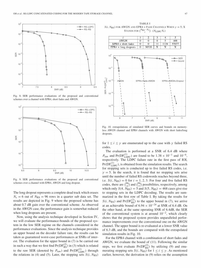
TABLE IS(i, NRS) FOR AWGN AND EPR4 + FADE CHANNELS WHEN γ = 5; X
STANDS FOR(NRS−Ne
i
) · (NLDPC Nt )
Fig. 10. extrapolations of simulated SER curves and bounds on memory-less AWGN channel and EPR4 channels with AWGN with short fades/longdropouts.
for 1 ≤ i ≤ γ are enumerated up to the case with γ failed RScodes.
The evaluation is performed at a SNR of 6.4 dB wherePraw and Pr(DF(1)
LDPC) are found to be 1.38 × 10⁻¹ and 10−6,respectively. The LDPC failure rate in the first pass of IOI,Pr(DF(1)
LDPC), is obtained from the simulation results. The searchfor stopping sets is conducted up to five failed RS codes, i.e.γ = 5. In the search, it is found that no stopping sets ariseuntil the number of failed RS codewords reaches beyond three,i.e. S(i, NRS) = 0 for i = 1, 2, 3. For four and five failed RScodes, there are
(964
)and
(965
)possibilities, respectively, among
which only S(4, NRS) = 5 and S(5, NRS) = 468 cases give riseto stopping sets in the LDPC decoding. The results are sum-marized in the first row of Table I. By taking the results forS(i, NRS) and Pr(DF(2)
RS) to the upper bound in (7), we arriveat an achievable bound of 6.94 × 10⁻²⁴ at SNR of 6.4 dB. Onthe other hand, at the same operating SNR of 6.4dB, the SERof the conventional system is at around 10−2, which clearlyshows that the proposed system provides unparalleled perfor-mance improvements over the conventional one on the AWGNchannel. The upper bound is re-evaluated at a lower SNR valueof 6.3 dB, and the bounds are compared with the extrapolatedsimulation results in Fig. 10.
For the EPR4 channel with a combination of short fades andAWGN, we evaluate the bound of (11). Following the similarsteps, we first evaluate Pr(DF(2)
RS) by utilizing (9) and enu-merating stopping sets S(i, NRS) for 1 ≤ i ≤ γ . As mentionedearlier, however, the derivation in (9) relies on the assumption

68 IEEE TRANSACTIONS ON COMMUNICATIONS, VOL. 64, NO. 1, JANUARY 2016
Fig. 11. Empirical distributions of Pr[ j], Pr[�] and Pr[ j |�] for � = 0, 1, . . . , 8over the EPR4 channel with short fades and AWGN at a SNR of 8.45dB.
that the numbers of bad bytes falling in message versus par-ity regions, j and �, respectively, are statistically independent,and thus the joint distribution can be expressed as a product ofmarginal distributions, Pr[ j, �] = Pr[ j] Pr[�]. To confirm thisassumption, the distributions Pr[ j |�] obtained empirically areplotted while varying � from 0 to 8 in Fig. 11. It is seen thatregardless of the value of �, the samples of Pr[ j |�] all contributeto outlining a single curve, which is labeled as Pr[�], confirmingthat Pr[ j |�] does not depend on �. The empirical distributionshave been gathered assuming that the duration of short ampli-tude fades results in an average burst length of 2-5 bytes in C1due to the interleaver structure at the channel input. The data iscollected at an SNR of 8.45 dB. Fig. 11 also shows empiricaldistributions of Pr[ j] and Pr[�].
Meanwhile, the LDPC failure rate Pr(DF(1)LDPC) = 10−6 at
the same SNR of 8.45 dB is observed for the channel consid-ered for generating the curves in Fig. 8. The corresponding RScode failure rate in the second pass, Pr(DF(2)
RS), can be com-puted by taking the empirical result into (9), which leads toPr(DF(2)
RS) = 4.84 × 10⁻⁷. Finally, the evaluation of the upperbound in (11) with S(i, NLDPC) in the second row of Table Iindicates that the upper bound on the LDPC failure rate in thesecond pass, Pr(DF(2)
2 ), is 1.24 × 10⁻¹⁸, which is more thansatisfactory. The evaluation of the upper bound is repeated ata SNR of 8.35 dB, and the result is shown along with theextrapolated simulation results in Fig. 10.
Finally, the decoder failure rate Pr(DF(2)LDPC) for the EPR4
channel with AWGN and long erasure dropouts is evaluated. Indoing so, as the first step, Pr(DF(1)
LDPC) is taken from the simu-
lation results where Pr(DF(1)LDPC) = 10−6 is seen to be achieved
at SNR of 10.55 dB. Then, the RS code failure rate in thesecond pass, Pr(DF(2)
RS) in (9), becomes 1.7 × 10⁻¹², which inturn results in a LDPC code failure rate in the second pass,Pr(DF(2)
LDPC), of 1.12 × 10⁻¹⁹. It should be noted that stoppingsets listed in the third row of Table I are caused by Ne + i erasedRS codes, and the number of combinations of failed RS codes
grows fast with increasing i . Thus, the search for the stoppingsets is conducted only up to γ = 2. Still, it can be seen that thebound is reasonably tight. The evaluation for the upper boundon Pr(DF(2)
LDPC) is conducted again at a SNR of 10.4 dB, and thebounds are compared with the extrapolation of the simulationsresults in Fig. 10. The evaluated bounds confirm that there areno error floors for the proposed RS-LDPC concatenated codingsystem down to the target SER range around 10−19.
VI. CONCLUSIONS
We proposed a novel error-control system utilizing RS-LDPC concatenation for the modern tape channel plagued bydifferent types of error mechanisms. The proposed schemeis significant in that 1) it gives large performance gain withrespect to the conventional RS-RS concatenation while per-forming comparable to the latter in erasure-dominant channels,2) despite the use of a non-binary LDPC outer code, the uti-lization of hard RS decoder decisions most of the time makesthe decoding complexity quite manageable, and 3) unlike anycoding scheme relying on LDPC codes, the proposed schemeallows performance analysis in low-error-rate regime. The the-oretical bound analysis indeed has confirmed that the proposedcoding scheme does not suffer from the usual error floor issuesof LDPC codes. While the current paper focuses on the tapechannel, the particular proposed concatenation finds applica-tions in other important areas including wireless channels withblock fading and power-line channels.
ACKNOWLEDGMENT
The authors are indebted by the encouragements, feed-back and constructive criticisms provided by Drs. ThomasMittelholzer and Roy Cideciyan of IBM Research and Drs. JWLee and Suayb Arslan of Quantum Corporation throughout theproject.
REFERENCES
[1] R. H. Dee, “Magnetic tape for data storage: An enduring technology,”Proc. IEEE, vol. 96, no. 11, pp. 1775–1785, Nov. 2008.
[2] E. Childers, W. Imaino, J. Eaton, G. Jaquette, P. Koeppe, and D. Hellman,“Six orders of magnitude in linear tape technology: The one-terabyteproject,” IBM J. Res. Develop., vol. 47, no. 4, pp. 471–482, Jul. 2003.
[3] R. H. Dee, “The challenges of magnetic recording on tape for datastorage (the one terabyte cartridge and beyond),” in Proc. 10th NASAGoddard Space Flight Center Conf. Mass Storage Syst. Technol., Apr.2002, pp. 109–119.
[4] R. H. Dee, “Magnetic tape: The challenge of reaching hard-disk-drivedata densities on flexible media,” MRS Bull., vol. 31, pp. 404–408,May 2006.
[5] Information Storage Industry Consortium (INSIC). (2005). MagneticTape Storage Roadmap, San Diego, CA, USA [Online]. Available:http://www.insic.org
[6] Information Storage Industry Consortium (INSIC). (2012, Mar.).International Magnetic Tape Storage Roadmap [Online]. Available:http://www.insic.org
[7] S. Sankaranarayanan and E. Eleftheriou, “Performance of product codeson channels with memory,” in Proc. IEEE Int. Symp. Inf. Theory, Sep.2005, pp. 548–552.
[8] Data Interchange on 12.7 mm 384-Track Magnetic Tape Cartridges,ECMA-319 Standard, 2001.
[9] S. Sahu, H. Song, and B. Vijaya Kumar, “Performance of low-densityparity-check (LDPC) codes on high-density magnetic tape recordingsignals,” in Proc. IEEE Int. Magn. Conf., Mar. 2003, pp. DT-10.

OH et al.: RS-LDPC CONCATENATED CODING FOR THE MODERN TAPE STORAGE CHANNEL 69
[10] Y. Han and W. Ryan, “Packet-LDPC codes for tape drives,” IEEE Trans.Magn., vol. 41, no. 4, pp. 1340–1347, Apr. 2005.
[11] Y. Han, W. Ryan, and R. Wesel, “Dual-mode decoding of product codeswith application to tape storage,” in Proc. IEEE Global Telecommun.Conf., Nov. 2005, vol. 3, pp. 1255–1260.
[12] Y. Han and W. Ryan, “Concatenating a structured LDPC code and a con-strained code to preserve soft-decoding, structure, and burst correction,”IEEE Trans. Magn., vol. 42, no. 10, pp. 2558–2560, Oct. 2006.
[13] Z. Li, J. Xie, and B. Kumar, “Low-density parity-check codes withvariable rate and randomized constraints for advanced magnetic taperecording,” in Proc. IEEE Int. Magn. Conf. Asia, Apr. 2005, pp. 1611–1612.
[14] D. Yang, R. Molstad, and Y. Yip, “Performance evaluation of LDPCcode on VR2 channel,” in Proc. IEEE Int. Magn. Conf. Eur., Apr. 2002,pp. AP2.
[15] B. Liu, Y. Li, B. Rong, L. Gui, and Y. Wu, “LDPC-RS product codesfor digital terrestrial broadcasting transmission system,” IEEE Trans.Broadcast., vol. 60, no. 1, pp. 38–49, Mar. 2014.
[16] S. I. Park et al., “LDPC-RS two dimensional code for the next gener-ation cloud transmission system,” in Proc. IEEE Int. Symp. BroadbandMultimedia Syst. Broadcast., Jun. 2014, pp. 1–2.
[17] M. Davey and D. J. C MacKay, “Low density parity check codes overGF(q),” in Proc. Inf. Theory Workshop, 1998, pp. 70–71.
[18] H. Wymeersch, H. Steendam, and M. Moeneclaey, “Log-domain decod-ing of LDPC codes over GF(q),” in Proc. IEEE Int. Conf. Commun., 2004,vol. 2, pp. 772–776.
[19] N. Andreadou and F.-N. Pavlidou, “Mitigation of impulsive noise effecton the PLC channel with QC-LDPC codes as the outer coding scheme,”IEEE Trans. Power Del., vol. 25, no. 3, pp. 1440–1449, Jul. 2010.
[20] T. Richardson, “Error floors of LDPC codes,” in Proc. 41st Allerton Conf.Commun. Control Comput., Oct. 2003, pp. 1426–1435.
[21] Y. Kou, S. Lin, and M. Fossorier, “Low-density parity-check codes basedon finite geometries: A rediscovery and new results,” IEEE Trans. Inf.Theory, vol. 47, no. 7, pp. 2711–2736, Nov. 2001.
[22] X.-Y. Hu, E. Eleftheriou, and D.-M. Arnold, “Progressive edge-growthTanner graphs,” in Proc. IEEE Global Telecommun. Conf., Nov. 2001,vol. 2, pp. 995–1001.
[23] T. Tian, C. Jones, J. Villasenor, and R. Wesel, “Construction of irregularLDPC codes with low error floors,” in Proc. IEEE Int. Conf. Commun.,May 2003, vol. 5, pp. 3125–3129.
[24] A. Abbasfar, D. Divsalar, and K. Yao, “Accumulate-repeat-accumulatecodes,” IEEE Trans. Commun., vol. 55, no. 4, pp. 692–702, Apr. 2007.
[25] Y. Zhang and W. Ryan, “Structured IRA codes: Performance analysisand construction,” IEEE Trans. Commun., vol. 55, no. 5, pp. 837–844,May 2007.
[26] Y. Zhang and W. Ryan, “Toward low LDPC-code floors: A case study,”IEEE Trans. Commun., vol. 57, no. 6, pp. 1566–1573, Jun. 2009.
[27] J. Lu and J. Moura, “Structured LDPC codes for high-density record-ing: Large girth and low error floor,” IEEE Trans. Magn., vol. 42, no. 2,pp. 208–213, Feb. 2006.
[28] H. Xiao and A. Banihashemi, “Graph-based message-passing schedulesfor decoding LDPC codes,” IEEE Trans. Commun., vol. 52, no. 12,pp. 2098–2105, Dec. 2004.
[29] G. Liva, W. Ryan, and M. Chiani, “Quasi-cyclic generalized LDPC codeswith low error floors,” IEEE Trans. Commun., vol. 56, no. 1, pp. 49–57,Jan. 2008.
[30] Y. Han and W. Ryan, “Low-floor decoders for LDPC codes,” IEEE Trans.Commun., vol. 57, no. 6, pp. 1663–1673, Jun. 2009.
[31] H. Thapar and A. Patel, “A class of partial response systems for increas-ing storage density in magnetic recording,” IEEE Trans. Magn., vol. 23,no. 5, pp. 3666–3668, Sep. 1987.
[32] B. Steingrimsson and J. Moon, “Dropout compensation in magnetictape channels by adaptive equalization and coding,” IEEE Trans. Magn.,vol. 37, no. 6, pp. 3981–3993, Nov. 2001.
[33] L. Bahl, J. Cocke, F. Jelinek, and J. Raviv, “Optimal decoding of lin-ear codes for minimizing symbol error rate (corresp.),” IEEE Trans. Inf.Theory, vol. 20, no. 2, pp. 284–287, Mar. 1974.
[34] J. Hagenauer and P. Hoeher, “A Viterbi algorithm with soft-decision out-puts and its applications,” in Proc. IEEE Global Telecommun. Conf., Nov.1989, vol. 3, pp. 1680–1686.
[35] A. Lafourcade and A. Vardy, “Optimal sectionalization of a trellis,” IEEETrans. Inf. Theory, vol. 42, no. 3, pp. 689–703, May 1996.
[36] P. Hoeher, “Optimal subblock-by-subblock detection,” IEEE Trans.Commun., vol. 43, nos. 2–4, pp. 714–717, Feb. 1995.
[37] V. Savin, “Non binary LDPC codes over the binary erasure channel:Density evolution analysis,” in Proc. IEEE Int. Symp. Appl. Sci. Biomed.Commun. Technol., Oct. 2008, pp. 1–5.
[38] I. Djordjevic and B. Vasic, “Nonbinary LDPC codes for optical com-munication systems,” IEEE Photonics Technol. Lett., vol. 17, no. 10,pp. 2224–2226, Oct. 2005.
[39] [Online]. Available: https://www.dropbox.com/sh/y1xeo1hew3n9vkl/AAD2AwOKaookvvLwjDlx2thea?dl=0
Jieun Oh received the B.S. degree in electrical engi-neering from Handong University, Pohang, SouthKorea, and the M.S. and Ph.D. degrees in electri-cal engineering from the Korea Advanced Instituteof Science and Technology (KAIST), Daejeon, SouthKorea, in 2009, 2011, and 2015, respectively. Herresearch interests include coding and informationtheory for the storage channels.
Jeongseok Ha (M’06) received the B.E. degree inelectronics from Kyungpook National University,Daegu, South Korea, the M.S. degree in electronicand electrical engineering from Pohang University ofScience and Technology, Pohang, South Korea, andthe Ph.D. degree in electrical and computer engineer-ing from the Georgia Institute of Technology, Atlanta,GA, USA, in 1992, 1994, and 2003, respectively.He is currently with the Korea Advanced Instituteof Science and Technology (KAIST), Daejeon, SouthKorea, as an Associate Professor. His research inter-
ests include theories and applications of error-control codes and physical layersecurity.
Hyegyeong Park (S’12) received the B.S. andM.S. degrees in electrical engineering from theKorea Advanced Institute of Science and Technology(KAIST), Daejeon, South Korea, in 2012 and 2014,respectively. She is currently pursuing the Ph.D.degree at KAIST. Her research interests include cod-ing and information theory with the current focus ondistributed storage.
Jaekyun Moon (F’05) received the Ph.D. degree inelectrical and computer engineering from CarnegieMellon University, Pittsburgh, PA, USA. He isa Professor of Electrical Engineering with KoreaAdvanced Institute of Science and Technology(KAIST), Daejeon, South Korea. From 1990 to2009, he was with the Faculty of the Departmentof Electrical and Computer Engineering, Universityof Minnesota, Twin Cities, Minneapolis, MN, USA.His research interests include channel characteriza-tion, signal processing, and coding for data storage
and digital communication. He served as the Program Chair for the 1997IEEE Magnetic Recording Conference. He is also the Past Chair of the SignalProcessing for Storage Technical Committee of the IEEE CommunicationsSociety. He served as a Guest Editor for the 2001 IEEE JOURNAL ON
SELECTED AREAS IN COMMUNICATIONS issue on Signal Processing for HighDensity Recording. He also served as an Editor for IEEE TRANSACTIONS
ON MAGNETICS in the area of signal processing and coding from 2001 to2006. He consulted as the Chief Scientist for DSPG, Inc. from 2004 to 2007.He also worked as the Chief Technology Officer at Link-A-Media DevicesCorp. He was the recipient of the McKnight Land-Grant Professorship fromthe University of Minnesota, and the IBM Faculty Development Awardsas well as the IBM Partnership Awards. He was also the recipient of theNational Storage Industry Consortium (NSIC) Technical Achievement Awardfor the invention of the maximum transition run (MTR) code, a widely usederror-control/modulation code in commercial storage systems.