Embed Size (px)
Citation preview
RSD-1 Digital Sharing Device
Version 1.0
INSTA
LLATIO
N A
ND
O
PER
ATIO
N M
AN
UA
L
The Access Company

RSD-1 Digital Sharing Device
Version 1.0
Installation and Operation Manual
Notice
This manual contains information that is proprietary to RAD Data Communications Ltd. ("RAD"). No part of this publication may be reproduced in any form whatsoever without prior written approval by RAD Data Communications.
Right, title and interest, all information, copyrights, patents, know-how, trade secrets and other intellectual property or other proprietary rights relating to this manual and to the RSD-1 and any software components contained therein are proprietary products of RAD protected under international copyright law and shall be and remain solely with RAD.
RSD-1 is a registered trademark of RAD. No right, license, or interest to such trademark is granted hereunder, and you agree that no such right, license, or interest shall be asserted by you with respect to such trademark.
You shall not copy, reverse compile or reverse assemble all or any portion of the Manual or the RSD-1. You are prohibited from, and shall not, directly or indirectly, develop, market, distribute, license, or sell any product that supports substantially similar functionality as the RSD-1, based on or derived in any way from the RSD-1. Your undertaking in this paragraph shall survive the termination of this Agreement.
This Agreement is effective upon your opening of the RSD-1 package and shall continue until terminated. RAD may terminate this Agreement upon the breach by you of any term hereof. Upon such termination by RAD, you agree to return to RAD the RSD-1 and all copies and portions thereof.
For further information contact RAD at the address below or contact your local distributor.
International Headquarters RAD Data Communications Ltd.
24 Raoul Wallenberg Street Tel Aviv 69719, Israel Tel: 972-3-6458181 Fax: 972-3-6498250, 6474436 E-mail: [email protected]
North America Headquarters RAD Data Communications Inc.
900 Corporate Drive Mahwah, NJ 07430, USA Tel: (201) 5291100, Toll free: 1-800-4447234 Fax: (201) 5295777 E-mail: [email protected]
© 1998–2008 RAD Data Communications Ltd. Publication No. 557-200-03/08

Limited Warranty
RAD warrants to DISTRIBUTOR that the hardware in the RSD-1 to be delivered hereunder shall be free of defects in material and workmanship under normal use and service for a period of twelve (12) months following the date of shipment to DISTRIBUTOR.
If, during the warranty period, any component part of the equipment becomes defective by reason of material or workmanship, and DISTRIBUTOR immediately notifies RAD of such defect, RAD shall have the option to choose the appropriate corrective action: a) supply a replacement part, or b) request return of equipment to its plant for repair, or c) perform necessary repair at the equipment's location. In the event that RAD requests the return of equipment, each party shall pay one-way shipping costs.
RAD shall be released from all obligations under its warranty in the event that the equipment has been subjected to misuse, neglect, accident or improper installation, or if repairs or modifications were made by persons other than RAD's own authorized service personnel, unless such repairs by others were made with the written consent of RAD.
The above warranty is in lieu of all other warranties, expressed or implied. There are no warranties which extend beyond the face hereof, including, but not limited to, warranties of merchantability and fitness for a particular purpose, and in no event shall RAD be liable for consequential damages.
RAD shall not be liable to any person for any special or indirect damages, including, but not limited to, lost profits from any cause whatsoever arising from or in any way connected with the manufacture, sale, handling, repair, maintenance or use of the RSD-1, and in no event shall RAD's liability exceed the purchase price of the RSD-1.
DISTRIBUTOR shall be responsible to its customers for any and all warranties which it makes relating to RSD-1 and for ensuring that replacements and other adjustments required in connection with the said warranties are satisfactory.
Software components in the RSD-1 are provided "as is" and without warranty of any kind. RAD disclaims all warranties including the implied warranties of merchantability and fitness for a particular purpose. RAD shall not be liable for any loss of use, interruption of business or indirect, special, incidental or consequential damages of any kind. In spite of the above RAD shall do its best to provide error-free software products and shall offer free Software updates during the warranty period under this Agreement.
RAD's cumulative liability to you or any other party for any loss or damages resulting from any claims, demands, or actions arising out of or relating to this Agreement and the RSD-1 shall not exceed the sum paid to RAD for the purchase of the RSD-1. In no event shall RAD be liable for any indirect, incidental, consequential, special, or exemplary damages or lost profits, even if RAD has been advised of the possibility of such damages.
This Agreement shall be construed and governed in accordance with the laws of the State of Israel.
Product Disposal
To facilitate the reuse, recycling and other forms of recovery of waste equipment in protecting the environment, the owner of this RAD product is required to refrain from disposing of this product as unsorted municipal waste at the end of its life cycle. Upon termination of the unit’s use, customers should provide for its collection for reuse, recycling or other form of environmentally conscientious disposal.
General Safety Instructions
The following instructions serve as a general guide for the safe installation and operation of telecommunications products. Additional instructions, if applicable, are included inside the manual.
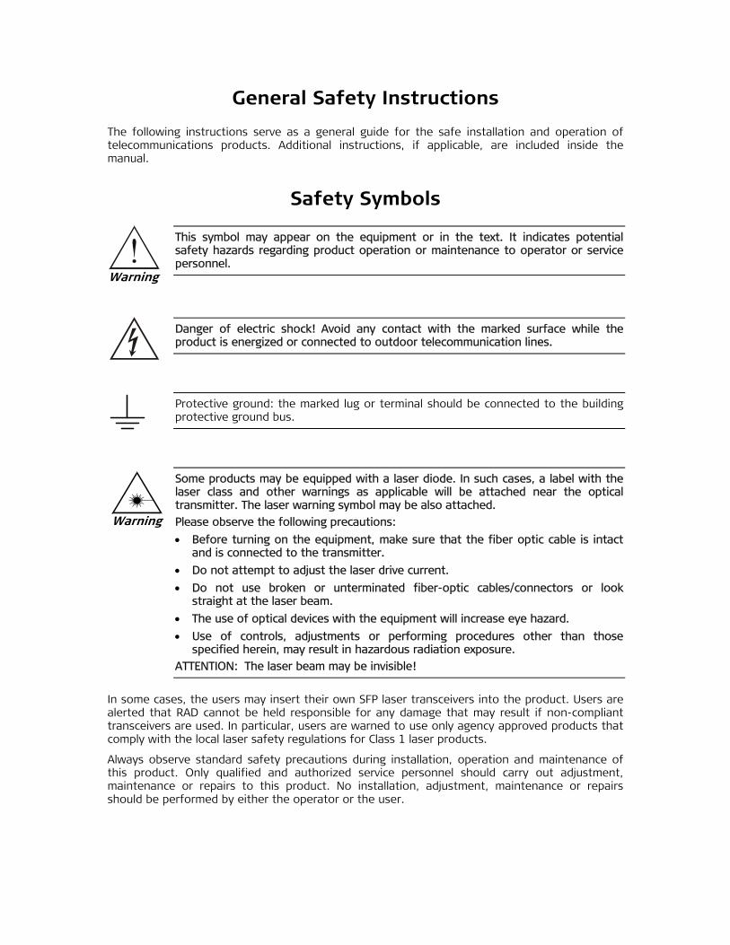
Safety Symbols
This symbol may appear on the equipment or in the text. It indicates potential safety hazards regarding product operation or maintenance to operator or service personnel.
Danger of electric shock! Avoid any contact with the marked surface while the product is energized or connected to outdoor telecommunication lines.
Protective ground: the marked lug or terminal should be connected to the building protective ground bus.
Some products may be equipped with a laser diode. In such cases, a label with the laser class and other warnings as applicable will be attached near the optical transmitter. The laser warning symbol may be also attached.
Please observe the following precautions:
• Before turning on the equipment, make sure that the fiber optic cable is intact and is connected to the transmitter.
• Do not attempt to adjust the laser drive current.
• Do not use broken or unterminated fiber-optic cables/connectors or look straight at the laser beam.
• The use of optical devices with the equipment will increase eye hazard.
• Use of controls, adjustments or performing procedures other than those specified herein, may result in hazardous radiation exposure.
ATTENTION: The laser beam may be invisible!
In some cases, the users may insert their own SFP laser transceivers into the product. Users are alerted that RAD cannot be held responsible for any damage that may result if non-compliant transceivers are used. In particular, users are warned to use only agency approved products that comply with the local laser safety regulations for Class 1 laser products.
Always observe standard safety precautions during installation, operation and maintenance of this product. Only qualified and authorized service personnel should carry out adjustment, maintenance or repairs to this product. No installation, adjustment, maintenance or repairs should be performed by either the operator or the user.
Warning
Warning

Handling Energized Products
General Safety Practices
Do not touch or tamper with the power supply when the power cord is connected. Line voltages may be present inside certain products even when the power switch (if installed) is in the OFF position or a fuse is blown. For DC-powered products, although the voltages levels are usually not hazardous, energy hazards may still exist.
Before working on equipment connected to power lines or telecommunication lines, remove jewelry or any other metallic object that may come into contact with energized parts.
Unless otherwise specified, all products are intended to be grounded during normal use. Grounding is provided by connecting the mains plug to a wall socket with a protective ground terminal. If a ground lug is provided on the product, it should be connected to the protective ground at all times, by a wire with a diameter of 18 AWG or wider. Rack-mounted equipment should be mounted only in grounded racks and cabinets.
Always make the ground connection first and disconnect it last. Do not connect telecommunication cables to ungrounded equipment. Make sure that all other cables are disconnected before disconnecting the ground.
Connecting AC Mains
Make sure that the electrical installation complies with local codes.
Always connect the AC plug to a wall socket with a protective ground.
The maximum permissible current capability of the branch distribution circuit that supplies power to the product is 16A. The circuit breaker in the building installation should have high breaking capacity and must operate at short-circuit current exceeding 35A.
Always connect the power cord first to the equipment and then to the wall socket. If a power switch is provided in the equipment, set it to the OFF position. If the power cord cannot be readily disconnected in case of emergency, make sure that a readily accessible circuit breaker or emergency switch is installed in the building installation.
In cases when the power distribution system is IT type, the switch must disconnect both poles simultaneously.
Connecting DC Power
Unless otherwise specified in the manual, the DC input to the equipment is floating in reference to the ground. Any single pole can be externally grounded.
Due to the high current capability of DC power systems, care should be taken when connecting the DC supply to avoid short-circuits and fire hazards.
DC units should be installed in a restricted access area, i.e. an area where access is authorized only to qualified service and maintenance personnel.
Make sure that the DC power supply is electrically isolated from any AC source and that the installation complies with the local codes.
The maximum permissible current capability of the branch distribution circuit that supplies power to the product is 16A. The circuit breaker in the building installation should have high breaking capacity and must operate at short-circuit current exceeding 35A.
Before connecting the DC supply wires, ensure that power is removed from the DC circuit. Locate the circuit breaker of the panel board that services the equipment and switch it to the OFF position. When connecting the DC supply wires, first connect the ground wire to the corresponding terminal, then the positive pole and last the negative pole. Switch the circuit breaker back to the ON position.
A readily accessible disconnect device that is suitably rated and approved should be incorporated in the building installation.
If the DC power supply is floating, the switch must disconnect both poles simultaneously.
Connecting Data and Telecommunications Cables
Data and telecommunication interfaces are classified according to their safety status.
The following table lists the status of several standard interfaces. If the status of a given port differs from the standard one, a notice will be given in the manual.
Ports Safety Status
V.11, V.28, V.35, V.36, RS-530, X.21, 10 BaseT, 100 BaseT, Unbalanced E1, E2, E3, STM, DS-2, DS-3, S-Interface ISDN, Analog voice E&M
SELV Safety Extra Low Voltage:
Ports which do not present a safety hazard. Usually up to 30 VAC or 60 VDC.
xDSL (without feeding voltage), Balanced E1, T1, Sub E1/T1
TNV-1 Telecommunication Network Voltage-1:
Ports whose normal operating voltage is within the limits of SELV, on which overvoltages from telecommunications networks are possible.
FXS (Foreign Exchange Subscriber) TNV-2 Telecommunication Network Voltage-2:
Ports whose normal operating voltage exceeds the limits of SELV (usually up to 120 VDC or telephone ringing voltages), on which overvoltages from telecommunication networks are not possible. These ports are not permitted to be directly connected to external telephone and data lines.
FXO (Foreign Exchange Office), xDSL (with feeding voltage), U-Interface ISDN
TNV-3 Telecommunication Network Voltage-3:
Ports whose normal operating voltage exceeds the limits of SELV (usually up to 120 VDC or telephone ringing voltages), on which overvoltages from telecommunication networks are possible.
Always connect a given port to a port of the same safety status. If in doubt, seek the assistance of a qualified safety engineer.
Always make sure that the equipment is grounded before connecting telecommunication cables. Do not disconnect the ground connection before disconnecting all telecommunications cables.
Some SELV and non-SELV circuits use the same connectors. Use caution when connecting cables. Extra caution should be exercised during thunderstorms.
When using shielded or coaxial cables, verify that there is a good ground connection at both ends. The grounding and bonding of the ground connections should comply with the local codes.
The telecommunication wiring in the building may be damaged or present a fire hazard in case of contact between exposed external wires and the AC power lines. In order to reduce the risk,

there are restrictions on the diameter of wires in the telecom cables, between the equipment and the mating connectors.
To reduce the risk of fire, use only No. 26 AWG or larger telecommunication line cords.
Pour réduire les risques s’incendie, utiliser seulement des conducteurs de télécommunications 26 AWG ou de section supérieure.
Some ports are suitable for connection to intra-building or non-exposed wiring or cabling only. In such cases, a notice will be given in the installation instructions.
Do not attempt to tamper with any carrier-provided equipment or connection hardware.
Electromagnetic Compatibility (EMC)
The equipment is designed and approved to comply with the electromagnetic regulations of major regulatory bodies. The following instructions may enhance the performance of the equipment and will provide better protection against excessive emission and better immunity against disturbances.
A good ground connection is essential. When installing the equipment in a rack, make sure to remove all traces of paint from the mounting points. Use suitable lock-washers and torque. If an external grounding lug is provided, connect it to the ground bus using braided wire as short as possible.
The equipment is designed to comply with EMC requirements when connecting it with unshielded twisted pair (UTP) cables. However, the use of shielded wires is always recommended, especially for high-rate data. In some cases, when unshielded wires are used, ferrite cores should be installed on certain cables. In such cases, special instructions are provided in the manual.
Disconnect all wires which are not in permanent use, such as cables used for one-time configuration.
The compliance of the equipment with the regulations for conducted emission on the data lines is dependent on the cable quality. The emission is tested for UTP with 80 dB longitudinal conversion loss (LCL).
Unless otherwise specified or described in the manual, TNV-1 and TNV-3 ports provide secondary protection against surges on the data lines. Primary protectors should be provided in the building installation.
The equipment is designed to provide adequate protection against electro-static discharge (ESD). However, it is good working practice to use caution when connecting cables terminated with plastic connectors (without a grounded metal hood, such as flat cables) to sensitive data lines. Before connecting such cables, discharge yourself by touching ground or wear an ESD preventive wrist strap.
Caution
Attention

FCC-15 User Information
This equipment has been tested and found to comply with the limits of the Class A digital device, pursuant to Part 15 of the FCC rules. These limits are designed to provide reasonable protection against harmful interference when the equipment is operated in a commercial environment. This equipment generates, uses and can radiate radio frequency energy and, if not installed and used in accordance with the Installation and Operation manual, may cause harmful interference to the radio communications. Operation of this equipment in a residential area is likely to cause harmful interference in which case the user will be required to correct the interference at his own expense.
Canadian Emission Requirements
This Class A digital apparatus meets all the requirements of the Canadian Interference-Causing Equipment Regulation.
Cet appareil numérique de la classe A respecte toutes les exigences du Règlement sur le matériel brouilleur du Canada.
Warning per EN 55022 (CISPR-22)
This is a class A product. In a domestic environment, this product may cause radio interference, in which case the user will be required to take adequate measures.
Cet appareil est un appareil de Classe A. Dans un environnement résidentiel, cet appareil peut provoquer des brouillages radioélectriques. Dans ces cas, il peut être demandé à l’utilisateur de prendre les mesures appropriées.
Das vorliegende Gerät fällt unter die Funkstörgrenzwertklasse A. In Wohngebieten können beim Betrieb dieses Gerätes Rundfunkströrungen auftreten, für deren Behebung der Benutzer verantwortlich ist.
Warning
Avertissement
Achtung
Fra
nça
is
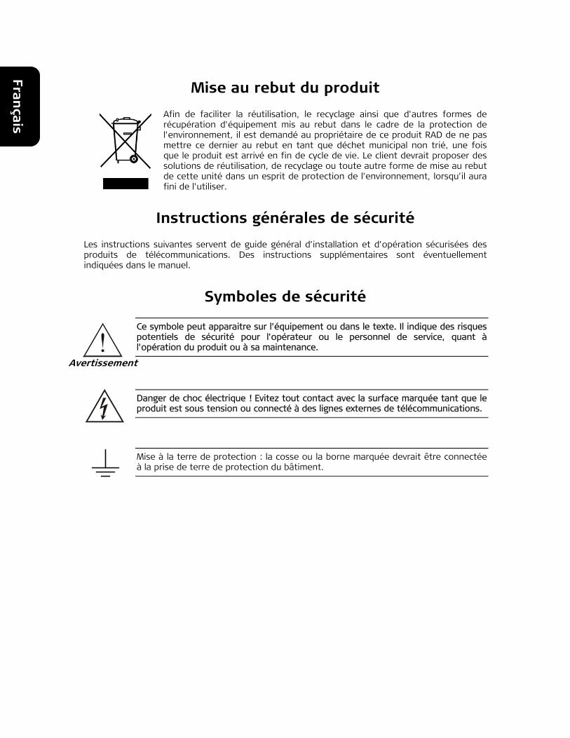
Mise au rebut du produit
Afin de faciliter la réutilisation, le recyclage ainsi que d'autres formes de récupération d'équipement mis au rebut dans le cadre de la protection de l'environnement, il est demandé au propriétaire de ce produit RAD de ne pas mettre ce dernier au rebut en tant que déchet municipal non trié, une fois que le produit est arrivé en fin de cycle de vie. Le client devrait proposer des solutions de réutilisation, de recyclage ou toute autre forme de mise au rebut de cette unité dans un esprit de protection de l'environnement, lorsqu'il aura fini de l'utiliser.
Instructions générales de sécurité
Les instructions suivantes servent de guide général d'installation et d'opération sécurisées des produits de télécommunications. Des instructions supplémentaires sont éventuellement indiquées dans le manuel.
Symboles de sécurité
Ce symbole peut apparaitre sur l'équipement ou dans le texte. Il indique des risques potentiels de sécurité pour l'opérateur ou le personnel de service, quant à l'opération du produit ou à sa maintenance.
Danger de choc électrique ! Evitez tout contact avec la surface marquée tant que le produit est sous tension ou connecté à des lignes externes de télécommunications.
Mise à la terre de protection : la cosse ou la borne marquée devrait être connectée à la prise de terre de protection du bâtiment.
Avertissement
Fra
nça
is
Certains produits peuvent être équipés d'une diode laser. Dans de tels cas, une étiquette indiquant la classe laser ainsi que d'autres avertissements, le cas échéant, sera jointe près du transmetteur optique. Le symbole d'avertissement laser peut aussi être joint.
Veuillez observer les précautions suivantes :
• Avant la mise en marche de l'équipement, assurez-vous que le câble de fibre optique est intact et qu'il est connecté au transmetteur.
• Ne tentez pas d'ajuster le courant de la commande laser.
• N'utilisez pas des câbles ou connecteurs de fibre optique cassés ou sans terminaison et n'observez pas directement un rayon laser.
• L'usage de périphériques optiques avec l'équipement augmentera le risque pour les yeux.
• L'usage de contrôles, ajustages ou procédures autres que celles spécifiées ici pourrait résulter en une dangereuse exposition aux radiations.
ATTENTION : Le rayon laser peut être invisible !
Les utilisateurs pourront, dans certains cas, insérer leurs propres émetteurs-récepteurs Laser SFP dans le produit. Les utilisateurs sont avertis que RAD ne pourra pas être tenue responsable de tout dommage pouvant résulter de l'utilisation d'émetteurs-récepteurs non conformes. Plus particulièrement, les utilisateurs sont avertis de n'utiliser que des produits approuvés par l'agence et conformes à la réglementation locale de sécurité laser pour les produits laser de classe 1.
Respectez toujours les précautions standards de sécurité durant l'installation, l'opération et la maintenance de ce produit. Seul le personnel de service qualifié et autorisé devrait effectuer l'ajustage, la maintenance ou les réparations de ce produit. Aucune opération d'installation, d'ajustage, de maintenance ou de réparation ne devrait être effectuée par l'opérateur ou l'utilisateur.
Manipuler des produits sous tension
Règles générales de sécurité
Ne pas toucher ou altérer l'alimentation en courant lorsque le câble d'alimentation est branché. Des tensions de lignes peuvent être présentes dans certains produits, même lorsque le commutateur (s'il est installé) est en position OFF ou si le fusible est rompu. Pour les produits alimentés par CC, les niveaux de tension ne sont généralement pas dangereux mais des risques de courant peuvent toujours exister.
Avant de travailler sur un équipement connecté aux lignes de tension ou de télécommunications, retirez vos bijoux ou tout autre objet métallique pouvant venir en contact avec les pièces sous tension.
Sauf s'il en est autrement indiqué, tous les produits sont destinés à être mis à la terre durant l'usage normal. La mise à la terre est fournie par la connexion de la fiche principale à une prise murale équipée d'une borne protectrice de mise à la terre. Si une cosse de mise à la terre est fournie avec le produit, elle devrait être connectée à tout moment à une mise à la terre de protection par un conducteur de diamètre 18 AWG ou plus. L'équipement monté en châssis ne devrait être monté que sur des châssis et dans des armoires mises à la terre.
Branchez toujours la mise à la terre en premier et débranchez-la en dernier. Ne branchez pas des câbles de télécommunications à un équipement qui n'est pas mis à la terre. Assurez-vous que tous les autres câbles sont débranchés avant de déconnecter la mise à la terre.
Avertissement
Fra
nça
is
Connexion au courant du secteur
Assurez-vous que l'installation électrique est conforme à la réglementation locale.
Branchez toujours la fiche de secteur à une prise murale équipée d'une borne protectrice de mise à la terre.
La capacité maximale permissible en courant du circuit de distribution de la connexion alimentant le produit est de 16A. Le coupe-circuit dans l'installation du bâtiment devrait avoir une capacité élevée de rupture et devrait fonctionner sur courant de court-circuit dépassant 35A.
Branchez toujours le câble d'alimentation en premier à l'équipement puis à la prise murale. Si un commutateur est fourni avec l'équipement, fixez-le en position OFF. Si le câble d'alimentation ne peut pas être facilement débranché en cas d'urgence, assurez-vous qu'un coupe-circuit ou un disjoncteur d'urgence facilement accessible est installé dans l'installation du bâtiment.
Le disjoncteur devrait déconnecter simultanément les deux pôles si le système de distribution de courant est de type IT.
Connexion d'alimentation CC
Sauf s'il en est autrement spécifié dans le manuel, l'entrée CC de l'équipement est flottante par rapport à la mise à la terre. Tout pôle doit être mis à la terre en externe.
A cause de la capacité de courant des systèmes à alimentation CC, des précautions devraient être prises lors de la connexion de l'alimentation CC pour éviter des courts-circuits et des risques d'incendie.
Les unités CC devraient être installées dans une zone à accès restreint, une zone où l'accès n'est autorisé qu'au personnel qualifié de service et de maintenance.
Assurez-vous que l'alimentation CC est isolée de toute source de courant CA (secteur) et que l'installation est conforme à la réglementation locale.
La capacité maximale permissible en courant du circuit de distribution de la connexion alimentant le produit est de 16A. Le coupe-circuit dans l'installation du bâtiment devrait avoir une capacité élevée de rupture et devrait fonctionner sur courant de court-circuit dépassant 35A.
Avant la connexion des câbles d'alimentation en courant CC, assurez-vous que le circuit CC n'est pas sous tension. Localisez le coupe-circuit dans le tableau desservant l'équipement et fixez-le en position OFF. Lors de la connexion de câbles d'alimentation CC, connectez d'abord le conducteur de mise à la terre à la borne correspondante, puis le pôle positif et en dernier, le pôle négatif. Remettez le coupe-circuit en position ON.
Un disjoncteur facilement accessible, adapté et approuvé devrait être intégré à l'installation du bâtiment.
Le disjoncteur devrait déconnecter simultanément les deux pôles si l'alimentation en courant CC est flottante.
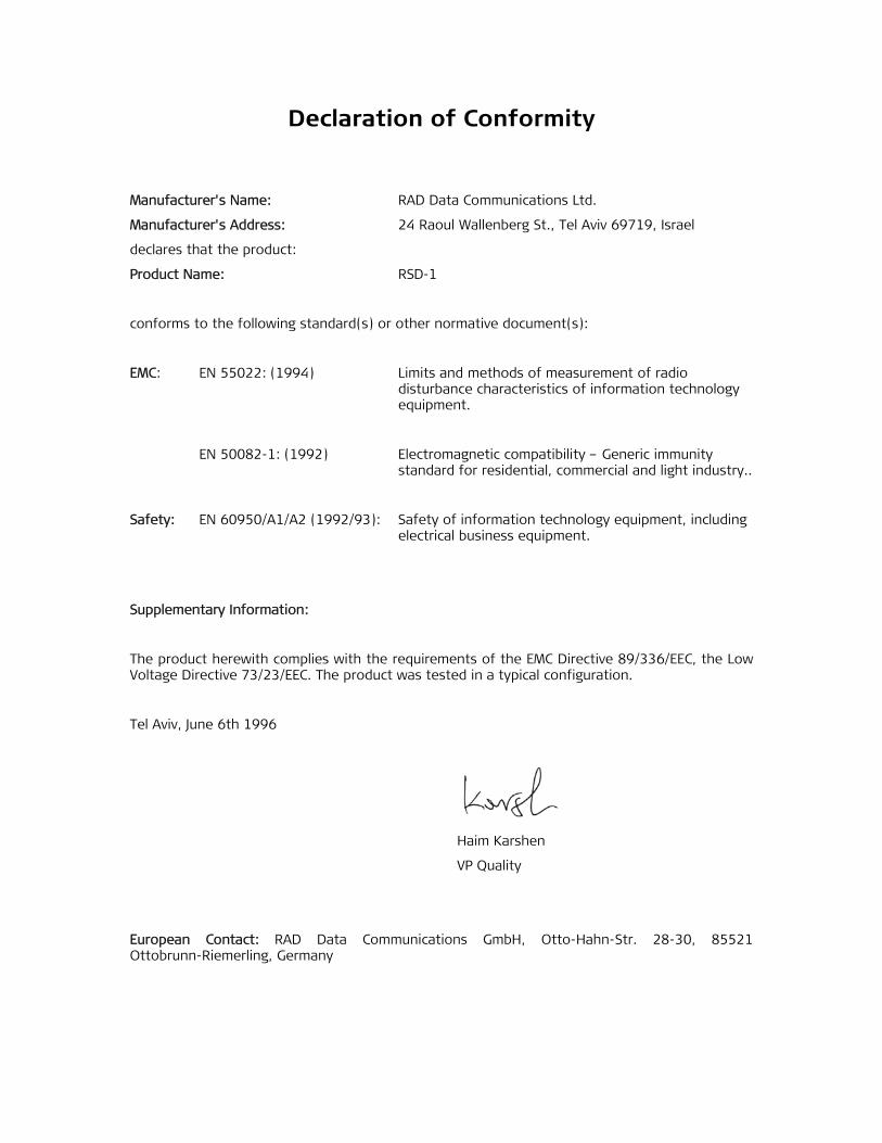
Declaration of Conformity
Manufacturer's Name: RAD Data Communications Ltd.
Manufacturer's Address: 24 Raoul Wallenberg St., Tel Aviv 69719, Israel
declares that the product:
Product Name: RSD-1
conforms to the following standard(s) or other normative document(s):
EMC: EN 55022: (1994) Limits and methods of measurement of radio disturbance characteristics of information technology equipment.
EN 50082-1: (1992) Electromagnetic compatibility – Generic immunity standard for residential, commercial and light industry..
Safety: EN 60950/A1/A2 (1992/93): Safety of information technology equipment, including electrical business equipment.
Supplementary Information:
The product herewith complies with the requirements of the EMC Directive 89/336/EEC, the Low Voltage Directive 73/23/EEC. The product was tested in a typical configuration.
Tel Aviv, June 6th 1996
Haim Karshen
VP Quality
European Contact: RAD Data Communications GmbH, Otto-Hahn-Str. 28-30, 85521 Ottobrunn-Riemerling, Germany

RSD-1 Ver. 1.0 1
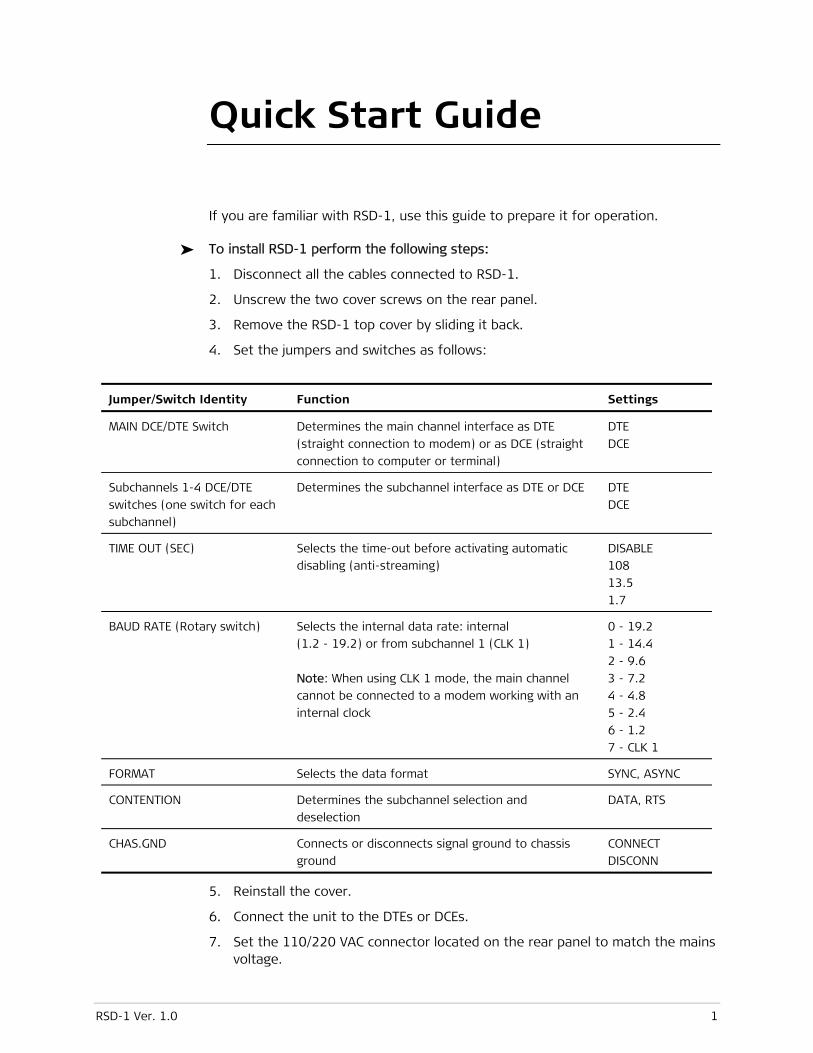
Quick Start Guide
If you are familiar with RSD-1, use this guide to prepare it for operation.
To install RSD-1 perform the following steps:
1. Disconnect all the cables connected to RSD-1.
2. Unscrew the two cover screws on the rear panel.
3. Remove the RSD-1 top cover by sliding it back.
4. Set the jumpers and switches as follows:
Jumper/Switch Identity Function Settings
MAIN DCE/DTE Switch Determines the main channel interface as DTE
(straight connection to modem) or as DCE (straight
connection to computer or terminal)
DTE
DCE
Subchannels 1-4 DCE/DTE
switches (one switch for each
subchannel)
Determines the subchannel interface as DTE or DCE DTE
DCE
TIME OUT (SEC) Selects the time-out before activating automatic
disabling (anti-streaming)
DISABLE
108
13.5
1.7
BAUD RATE (Rotary switch) Selects the internal data rate: internal
(1.2 - 19.2) or from subchannel 1 (CLK 1)
Note: When using CLK 1 mode, the main channel
cannot be connected to a modem working with an
internal clock
0 - 19.2
1 - 14.4
2 - 9.6
3 - 7.2
4 - 4.8
5 - 2.4
6 - 1.2
7 - CLK 1
FORMAT Selects the data format SYNC, ASYNC
CONTENTION Determines the subchannel selection and
deselection
DATA, RTS
CHAS.GND Connects or disconnects signal ground to chassis
ground
CONNECT
DISCONN
5. Reinstall the cover.
6. Connect the unit to the DTEs or DCEs.
7. Set the 110/220 VAC connector located on the rear panel to match the mains voltage.
Quick Start Guide Installation and Operation Manual
2 RSD-1 Ver. 1.0
8. Connect RSD-1 to the mains outlet. Make sure to connect the power cable to the power connector first and only then to the mains outlet.
9. Power the unit by setting the ON/OFF switch to ON.
RSD-1 Ver. 1.0 i
Contents
Chapter 1. Introduction 1.1 Overview....................................................................................................................1-1
Applications............................................................................................................1-1 Features .................................................................................................................1-2
Parallel Broadcast...............................................................................................1-2 Subchannel Disabling .........................................................................................1-2 LEDs ..................................................................................................................1-2
1.2 Physical Description ...................................................................................................1-2 Front Panel.............................................................................................................1-3 Rear Panel ..............................................................................................................1-3 Jumpers and Switches .............................................................................................1-3
1.3 Functional Description................................................................................................1-3 Timing ....................................................................................................................1-3 Main Principles of Operation ...................................................................................1-4
Contention.........................................................................................................1-4 Automatic SubChannel Disable ...........................................................................1-4 Control Signals ...................................................................................................1-4
Functional Block Diagram ........................................................................................1-5 1.4 Technical Specifications..............................................................................................1-7
Chapter 2. Installation and Setup 2.1 Site Requirements & Prerequisites .............................................................................2-1 2.2 Package Contents ......................................................................................................2-1 2.3 Installation and Setup ................................................................................................2-2
Setting the Internal Jumpers and Switches...............................................................2-2 Opening the RSD-1 Case ....................................................................................2-2 Setting the Internal Jumpers and Switches ..........................................................2-3
2.4 System Synchronization and Clock Distribution...........................................................2-4 Synchronizing the System .......................................................................................2-4
Synchronizing on the Main Channel DCE Clock.....................................................2-4 Synchronizing on the RSD-1 Internal Clock..........................................................2-5 Synchronizing on Subchannel 1 ..........................................................................2-5
Setting Up in an Asynchronous System ...................................................................2-6 Reinstalling the RSD-1 Cover...................................................................................2-6
2.5 Mounting the Unit......................................................................................................2-6 2.6 Interfaces and Connections........................................................................................2-7
Connecting the Interfaces .......................................................................................2-7 Connecting the Power.............................................................................................2-7
Connecting AC Power .........................................................................................2-7 Connecting DC Power .........................................................................................2-8
Chapter 3. Operation 3.1 Front Panel Controls and Indicators ............................................................................3-1 3.2 Operating RSD-1........................................................................................................3-2
Setup .....................................................................................................................3-2 Powering On...........................................................................................................3-2 Operation ...............................................................................................................3-2 Powering Off ..........................................................................................................3-2
Table of Contents Installation and Operation Manual
ii RSD-1 Ver. 1.0
Chapter 4. Troubleshooting and Diagnostics 4.1 Detecting Errors.........................................................................................................4-1
Power Supply..........................................................................................................4-1 RSD-1 Malfunction..................................................................................................4-1
RSD-1 Ver. 1.0 Overview 1-1
Chapter 1
Introduction
1.1 Overview
RSD-1 is a Digital Sharing Device that enables up to 4 modems or terminals to share a master modem, a multiplexer, or a computer port in a multipoint environment. It operates with asynchronous or synchronous equipment at data rates up to 19.2 kbps.
Applications
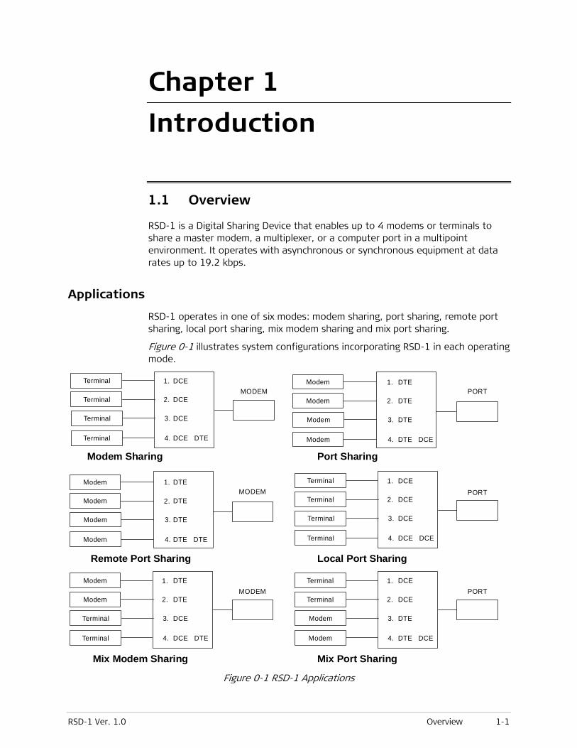
RSD-1 operates in one of six modes: modem sharing, port sharing, remote port sharing, local port sharing, mix modem sharing and mix port sharing.
Figure 0-1 illustrates system configurations incorporating RSD-1 in each operating mode.
Terminal
Terminal
Terminal
Terminal
MODEM1.
2.
3.
4.
DCE
DCE
DCE
DCE DTE
Terminal
Terminal
Terminal
Terminal
1.
2.
3.
4.
DCE
DCE
DCE
DCE DCE
Terminal
Terminal
1.
2.
3.
4.
DCE
DCE
DTE
DTE DCE
Terminal
Terminal
MODEM1.
2.
3.
4.
DTE
DTE
DCE
DCE DTE
Modem
Modem
Modem
Modem
Modem
Modem
Modem
Modem
MODEM1.
2.
3.
4.
DTE
DTE
DTE
DTE DTE
Modem
Modem
Modem
Modem
PORT
PORT
PORT
1.
2.
3.
4.
DTE
DTE
DTE
DTE DCE
Modem Sharing
Remote Port Sharing
Mix Modem Sharing Mix Port Sharing
Local Port Sharing
Port Sharing
Figure 0-1 RSD-1 Applications
Chapter 1 Introduction Installation and Operation Manual
1-2 Physical Description RSD-1 Ver. 1.0
The following should be taken into consideration when configuring an RSD-1 system:
• The rate of the subchannel and main channel modems and/or ports connected to RSD-1 must be equal to the data rate set within RSD-1. This is important for both asynchronous and synchronous systems.
• You should configure the RSD-1 subchannels as all synchronous or all asynchronous only. Asynchronous equipment may not be mixed with synchronous equipment on the same RSD-1.
Features
Parallel Broadcast
The RSD-1 main channel broadcasts information to all subchannels in parallel. Subchannels contend to transmit to the main channel by activating RTS/DCD, or by data transition (strap-selectable).
Subchannel Disabling
A subchannel can be disabled by automatic circuitry if it stays active for longer than a preset time and blocks all other subchannels. The automatic disable resets itself as soon as the subchannel RTS/DCD drops or 15 idle bits are transmitted. A LED indicator lights up for each subchannel disabled by automatic circuitry. A subchannel can also be disabled manually with front panel push buttons.
LEDs
Front panel LED indicators provide information on RSD-1 general status (power and data flow from the main channel to the subchannels), show which subchannel has gained access to the main channel, and if one of the subchannels has been automatically disabled.
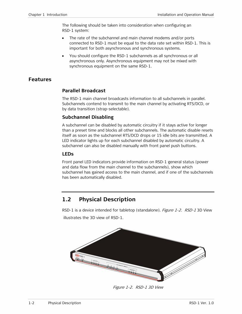
1.2 Physical Description
RSD-1 is a device intended for tabletop (standalone). Figure 1-2. RSD-1 3D View
illustrates the 3D view of RSD-1.
Figure 1-2. RSD-1 3D View
Installation and Operation Manual Chapter 1 Introduction
RSD-1 Ver. 1.0 Functional Description 1-3
Front Panel
The front panel of RSD-1 has push buttons for subchannel disabling and LEDs which provide real-time indications related to the operation and status of the unit. For more details about the RSD-1 push buttons and LEDs, refer to Section 3.1, Front Panel Controls and Indicators, in Chapter 3.
Rear Panel
The RSD-1 electrical and interface connectors are located on the rear panel. The RSD-1 interface includes five D-type, 25-pin female RS-232/V.24 connectors (DCE or DTE). One of the connectors is used for the main channel and the other four, for the subchannels. Refer to Section 2.5, Interfaces and Connections, in Chapter 2.
Jumpers and Switches
The jumpers and switches are located on the RSD-1 board. For more details about RSD-1 jumpers and switches, refer to Section 2.3, Installation and Setup, and Section 2.4, System Synchronization and Clock Distribution, in Chapter 2.
1.3 Functional Description The main channel of RSD-1 broadcasts information to all subchannels in parallel. Subchannels contend to transmit to the main channel by activating RTS/DCD or by data transition (strap-selectable). If the RTS/DCD or data of a subchannel is active, the subchannel’s transmit data and control signals are connected to the main channel. When RTS/DCD drops or data transitions stops, the control circuitry will switch to monitor other subchannels. A subchannel is disconnected immediately after it drops RTS/DCD or transmits 15 idle bits (strap-selectable).
A subchannel can be disabled automatically if it stays active for longer than a preset time and blocks all other subchannels (streaming). The automatic disable resets itself as soon as the subchannel’s RTS/DCD drops, or 15 idle bits are transmitted (Data Contention). One of the SUBCHANNEL DISABLE LED indicators on the front panel will light up if the appropriate subchannels is disabled.
Timing
Three clock modes are supported:
• Internal
• External from the main channel
• External from subchannel 1.
A built-in buffer overcomes phase differences that might exist between the clocks of modems connected to the subchannels and the RSD-1 main channel transmit clock.
Chapter 1 Introduction Installation and Operation Manual
1-4 Functional Description RSD-1 Ver. 1.0
Main Principles of Operation
Contention
Subchannel access to the main channel for data transmission is controlled by RTS/DCD (Request to Send/Data Carrier Detect) or data contention. When selected, the active subchannel’s data and timing signals pass through the contention circuit and the subchannel’s SELECT/DESELECT circuit to the elastic buffer, where data is clocked in and out of the main channel.
An internally generated high-speed lock is provided by the system clock module to the buffer, when working with asynchronous data. This minimizes bias distortion. When a continuous mark is detected, and RSD-1 is set to data contention, the select/deselect circuit will break the data path of the active subchannel. It then selects another subchannel and resets the buffer.
Otherwise, the subchannel remains connected until RTS/DCD goes down.
Automatic SubChannel Disable
A streaming subchannel is automatically disabled if it has stayed active for longer than a preset period of time, thereby blocking all other subchannels. Automatic disabling of a subchannel resets itself each time RTS/DCD or data (in data contention mode) drops.
Three different time delays may be selected: 1.7, 13.5, or 108 seconds. Alternatively, one may also select a non-active mode.
If a DTE subchannel (connected to a modem) is disabled automatically, RSD-1 will drop RTS, and if a DCE subchannel (connected to a port) is disabled, RSD-1 will drop DCD and CTS. In addition, RSD-1 will stop transmitting data to the subchannel and will ignore any data received from it.
Control Signals
Subchannel control signals are combined to provide a composite signal to the main channel. Control signals from the main channel are passed to all subchannels in parallel. See Table 1-1.
Installation and Operation Manual Chapter 1 Introduction
RSD-1 Ver. 1.0 Functional Description 1-5
Table 0-1 Main and Subchannel Control Signals
Main Channel Subchannel
RTS (DCD) In RTS/DCD contention mode - Follows
RTS (DCD) of the selected subchannel.
In Data Contention mode - “ON” if one of
the subchannels RTS (DCD) is “ON”.
Follows the main channel RTS (DCD) unless the
subchannel is disabled.
CTS “ON” only when the CTS signals of all
active subchannels are “ON”. A
subchannel is active if it is connected to
a modem and the DSR signal is “ON”
(enables connection of dial-up modems
to the RSD–1)
In RTS contention mode: Selected channel
follows CTS signal of main channel.
In Data Contention mode: Subchannel receives
CTS from main channel immediately after it
raises RTS, unless the subchannel is disabled.
DSR (DTR) “ON” if one of the subchannel’s DTR
(DSR) is “ON”.
Follows the main channel DSR (DTR).
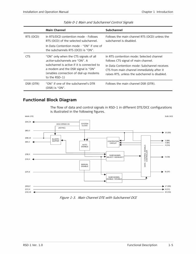
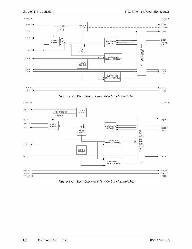
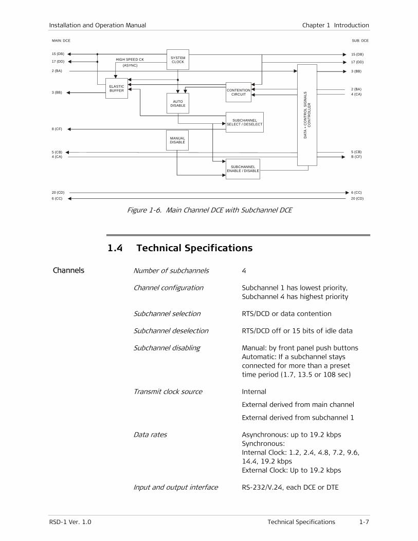
Functional Block Diagram
The flow of data and control signals in RSD-1 in different DTE/DCE configurations is illustrated in the following figures.
(DA) 24
(BD) 3
(DB) 15
(BA) 2
(CB) 5
(CA) 4
(CF) 8
(DD)17
(CC) 6(CD) 20 20 (CD)
6 (CC)
17 (DD)
B (CF)
5 (CB)
4 (CA)2 (BA)3 (BB)
15 (DD)
SUB: DCEMAIN: DTE
SYSTEMCLOCK
ELASTICBUFFER
AUTODISABLE
MANUALDISABLE
CONTENTIONCIRCUIT
SUBCHANNELENABLE / DISABLE
SUBCHANNELSELECT / DESELECT
DAT
A +
CO
NTR
OL
SIG
NAL
S
CO
NTR
OLL
ER
HIGH SPEED CK
(ASYNC)
Figure 1-3. Main Channel DTE with Subchannel DCE
Chapter 1 Introduction Installation and Operation Manual
1-6 Functional Description RSD-1 Ver. 1.0
15 (DB)
2 (BA)
3 (BB)
17 (DD)
8 (CF)
5 (CB)4 (CA)
20 (CD)
6 (CC)
17 (DD)8 (CF)
5 (CB)4 (CA)
20 (CD)
6 (CC)
3 (DB)
2 (BA)
15 (CKA)
24 (DA)
SUB: DTEMAIN: DCE
SYSTEMCLOCK
ELASTICBUFFER
AUTODISABLE
MANUALDISABLE
CONTENTIONCIRCUIT
SUBCHANNELENABLE / DISABLE
SUBCHANNELSELECT / DESELECT
DAT
A +
CO
NTR
OL
SIG
NA
LS
CO
NTR
OLL
ER
HIGH SPEED CK
(ASYNC)
BBDD
Figure 1-4. Main Channel DCE with Subchannel DTE
(DA) 24
(BB) 3
(DB) 15
(BA) 2
(CA) 4
(CF) 8
(DD)17
(CC) 6
(CD) 20 6 (CC)
20 (CD)
24 (DA)
4 (CA)
8 (CF)3 (BB)17 (DD)
2 (BA)
SUB: DTEMAIN: DTE
SYSTEMCLOCK
ELASTICBUFFER
AUTODISABLE
MANUALDISABLE
CONTENTIONCIRCUIT
SUBCHANNELENABLE / DISABLE
SUBCHANNELSELECT / DESELECT
DAT
A +
CO
NTR
OL
SIG
NA
LS
CO
NTR
OLL
ER
HIGH SPEED CK
(ASYNC)
Figure 1-5. Main Channel DTE with Subchannel DTE
Installation and Operation Manual Chapter 1 Introduction
RSD-1 Ver. 1.0 Technical Specifications 1-7
MAIN: DCE
15 (DB)
17 (DD)
2 (BA)
3 (BB)
8 (CF)
5 (CB)4 (CA)
20 (CD)
6 (CC)
6 (CC)
B (CF)5 (CB)
4 (CA)2 (BA)
3 (BB)
17 (DD)
15 (DB)
SUB: DCE
SYSTEMCLOCKHIGH SPEED CK
(ASYNC)
ELASTICBUFFER
AUTODISABLE
CONTENTIONCIRCUIT
DAT
A +
CO
NTR
OL
SIG
NA
LS
CO
NTR
OLL
ER
SUBCHANNELENABLE / DISABLE
SUBCHANNELSELECT / DESELECT
MANUALDISABLE
20 (CD)
Figure 1-6. Main Channel DCE with Subchannel DCE
1.4 Technical Specifications
Channels Number of subchannels 4
Channel configuration Subchannel 1 has lowest priority, Subchannel 4 has highest priority
Subchannel selection RTS/DCD or data contention
Subchannel deselection RTS/DCD off or 15 bits of idle data
Subchannel disabling Manual: by front panel push buttons Automatic: If a subchannel stays connected for more than a preset time period (1.7, 13.5 or 108 sec)
Transmit clock source Internal
External derived from main channel
External derived from subchannel 1
Data rates Asynchronous: up to 19.2 kbps Synchronous: Internal Clock: 1.2, 2.4, 4.8, 7.2, 9.6, 14.4, 19.2 kbps External Clock: Up to 19.2 kbps
Input and output interface RS-232/V.24, each DCE or DTE
Chapter 1 Introduction Installation and Operation Manual
1-8 Technical Specifications RSD-1 Ver. 1.0
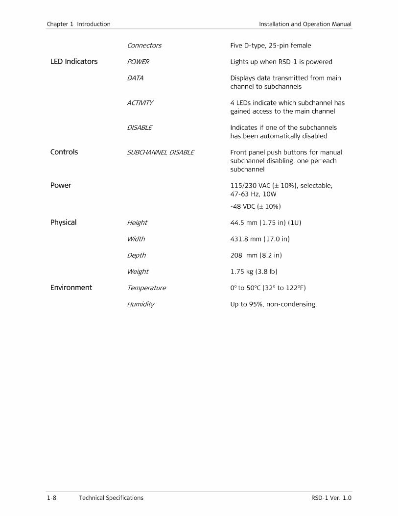
Connectors Five D-type, 25-pin female
LED Indicators POWER Lights up when RSD-1 is powered
DATA Displays data transmitted from main channel to subchannels
ACTIVITY 4 LEDs indicate which subchannel has gained access to the main channel
DISABLE Indicates if one of the subchannels has been automatically disabled
Controls SUBCHANNEL DISABLE Front panel push buttons for manual subchannel disabling, one per each subchannel
Power 115/230 VAC (± 10%), selectable, 47-63 Hz, 10W
-48 VDC (± 10%)
Physical Height 44.5 mm (1.75 in) (1U)
Width 431.8 mm (17.0 in)
Depth 208 mm (8.2 in)
Weight 1.75 kg (3.8 lb)
Environment Temperature 0o to 50oC (32o to 122oF)
Humidity Up to 95%, non-condensing
RSD-1 Ver. 1.0 Package Contents 2-1
Chapter 2
Installation and Setup
This chapter explains how to configure and install RSD-1. The information presented in this chapter includes:
• Site requirements for installing RSD-1
• Package contents
• Installation and setup procedures
• System synchronization and clock distribution
• Interfaces and connections
Before installing the product, review Handling Energized Products at the beginning of the manual.
2.1 Site Requirements & Prerequisites
RSD-1 is designed for tabletop or 19'' rack installation.
Install an AC-powered RSD-1 within 1.5 m (5 ft) of an easily accessible grounded AC outlet that furnishes 115 VAC or 230 VAC, depending on rated voltage of unit.
A DC-powered RSD-1 requires a -48 VDC power source, which must be adequately isolated from the mains supply.
The unit must be situated within 15 m (50 ft) of the associated data terminals or modems.
Allow at least 90 cm (36 in) at the front of RSD-1 for operating and maintenance access. Ensure that there is at least 10 cm (4 in) clearance at the rear of the unit for power and interface cables.
The ambient operating temperature of RSD-1 should be 0° to 50°C (32° to 122°F), at a relative humidity of up to 95%, non-condensing.
2.2 Package Contents
RSD-1 package includes the following items:
• RSD-1 unit
• RSD-1 Installation and Operation Manual
• AC power cord or DC power supply connector kit
Note
Chapter 2 Installation and Setup Installation and Operation Manual
2-2 Installation and Setup RSD-1 Ver. 1.0
• RM-7 New – hardware for mounting RSD-1 in a 19” rack (if ordered).
2.3 Installation and Setup
RSD-1 is a standalone device designed for tabletop or 19'' rack installation. It is delivered completely assembled. No provisions are made for bolting the RSD-1 to the tabletop.
Disconnect the AC power cord before performing the following procedures. Installation, operation and maintenance should only be performed by an experienced technician.
To install RSD-1, perform the following:
1. Determine the required configuration of RSD-1, according to your application and set the internal switches and jumpers accordingly.
2. Connect the RSD-1 main channel and subchannels.
3. Connect power to the unit.
Setting the Internal Jumpers and Switches
To set the internal jumpers and switches:
1. Open the RSD-1 case, identify jumper and switch locations and settings (see Figure 2-1).
2. Change settings as required.
3. Reinstall the RSD-1 cover.
Access to the inside of the equipment is permitted only to authorized and qualified service personnel.
To avoid accidental electric shock, always disconnect the interface cables and power cord before removing the unit from its casing.
Line voltages are present inside RSD-1 when it is connected to power.
Any adjustment, maintenance, and repair of the opened instrument under voltage should be avoided as much as possible and, when inevitable, should be carried out only by a skilled technician who is aware of the hazard involved. Capacitors inside the instrument may still be charged even after the instrument has been disconnected from its source of supply.
Opening the RSD-1 Case
To open the case:
1. Disconnect all the cables connected to RSD-1.
2. Unscrew the two cover screws on the rear panel.
3. Remove the RSD-1 top cover by sliding it back.
Warning
Warning
Installation and Operation Manual Chapter 2 Installation and Setup
RSD-1 Ver. 1.0 Installation and Setup 2-3
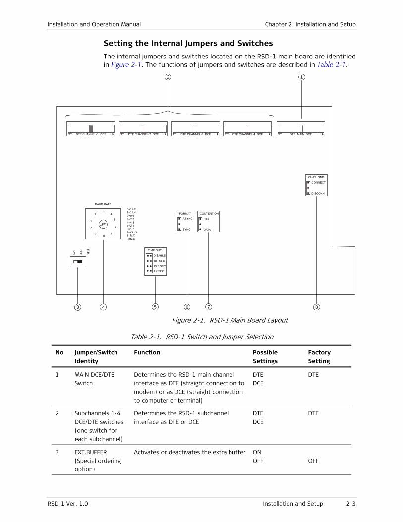
Setting the Internal Jumpers and Switches
The internal jumpers and switches located on the RSD-1 main board are identified in Figure 2-1. The functions of jumpers and switches are described in Table 2-1.
DTE CHANNEL-1 DCE DTE CHANNEL-2 DCE
1
23
4
BAUD RATE
TIME OUT
DISABLE
108 SEC
13.5 SEC
1.7 SEC
0=19.21=14.42=9.63=7.24=4.85=2.46=1.27=CLK18=N.C9=N.C
E.B.
OFF
ON
5
6
78
9
0
DTE CHANNEL-3 DCE DTE CHANNEL-4 DCE DTE MAIN DCE
FORMAT
ASYNC
SYNC
CONTENTION
CHAS. GND.
RTS
CONNECT
DATA
DISCONN
4 5
1
3 6 7 8
2
Figure 2-1. RSD-1 Main Board Layout
Table 2-1. RSD-1 Switch and Jumper Selection
No Jumper/Switch Identity
Function Possible Settings
Factory Setting
1 MAIN DCE/DTE
Switch
Determines the RSD-1 main channel
interface as DTE (straight connection to
modem) or as DCE (straight connection
to computer or terminal)
DTE
DCE
DTE
2 Subchannels 1-4
DCE/DTE switches
(one switch for
each subchannel)
Determines the RSD-1 subchannel
interface as DTE or DCE
DTE
DCE
DTE
3 EXT.BUFFER
(Special ordering
option)
Activates or deactivates the extra buffer ON
OFF
OFF
Chapter 2 Installation and Setup Installation and Operation Manual
2-4 System Synchronization and Clock Distribution RSD-1 Ver. 1.0
No Jumper/Switch Identity
Function Possible Settings
Factory Setting
4 BAUD RATE Rotary
switch
Selects the RSD-1 internal data rate:
internal (1.2 - 19.2) or from subchannel
1 (CLK 1)
Note: When using CLK 1 mode, the
main channel cannot be connected to a
modem working with an internal clock
0 - 19.2
1 - 14.4
2 - 9.6
3 - 7.2
4 - 4.8
5 - 2.4
6 - 1.2
7 - CLK 1
9.6
5 TIME OUT (SEC)
Jumper
Selects the time-out before activating
automatic disabling (anti-streaming)
DISABLE
108 sec
13.5 sec
1.7 sec
108 sec
6 FORMAT
Jumper
Selects the data format ASYNC
SYNC
SYNC
7 CONTENTION
Jumper
Determines the subchannel selection
and deselection
RTS
DATA
RTS
8 CHAS.GND
Jumper
Connects or disconnects signal ground
to chassis ground
CONNECT
DISCONN
DISCONN
2.4 System Synchronization and Clock Distribution
Synchronizing the System
Three alternatives are available for synchronizing the system:
• Synchronizing on the main channel’s clock (see Figure 2-2)
• Synchronizing on the RSD-1 internal clock (see Figure 2-3)
• Synchronizing on subchannel 1 modem timing signals (see Figure 2-4).
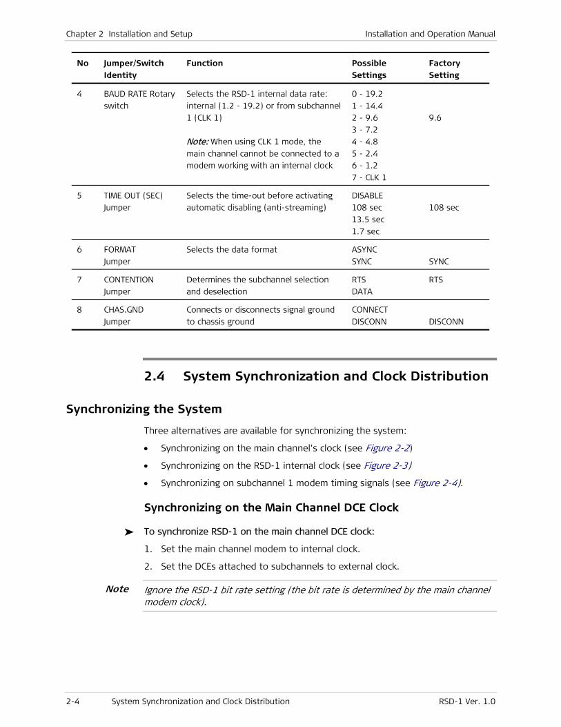
Synchronizing on the Main Channel DCE Clock
To synchronize RSD-1 on the main channel DCE clock:
1. Set the main channel modem to internal clock.
2. Set the DCEs attached to subchannels to external clock.
Ignore the RSD-1 bit rate setting (the bit rate is determined by the main channel modem clock).
Note
Installation and Operation Manual Chapter 2 Installation and Setup
RSD-1 Ver. 1.0 System Synchronization and Clock Distribution 2-5
MODEM 15
DCESUB DTE
RSD-1
SUB DCE
MAIN CHANNEL
24
DTE15
INT.CK
EXT.CK
Figure 2-2. Synchronizing on the Main Channel’s DCE Clock
Synchronizing on the RSD-1 Internal Clock
To synchronize RSD-1 on the internal clock:
1. Set the BIT RATE rotary switch to the required speed.
2. Set the DCEs attached to subchannels to external clock (EXT CLK).
3. Set the DCE attached to the main channel to external clock.
DCE
DTEDTE
EXT.CKMAINDCE
MAINDTE
SUB DCE
SUB DTE
RSD - 1
EXT.CK
SU
BC
HA
NN
EL
DCEEXT.CK 15
1515
2424
Figure 2-3. Synchronizing on the Internal Clock
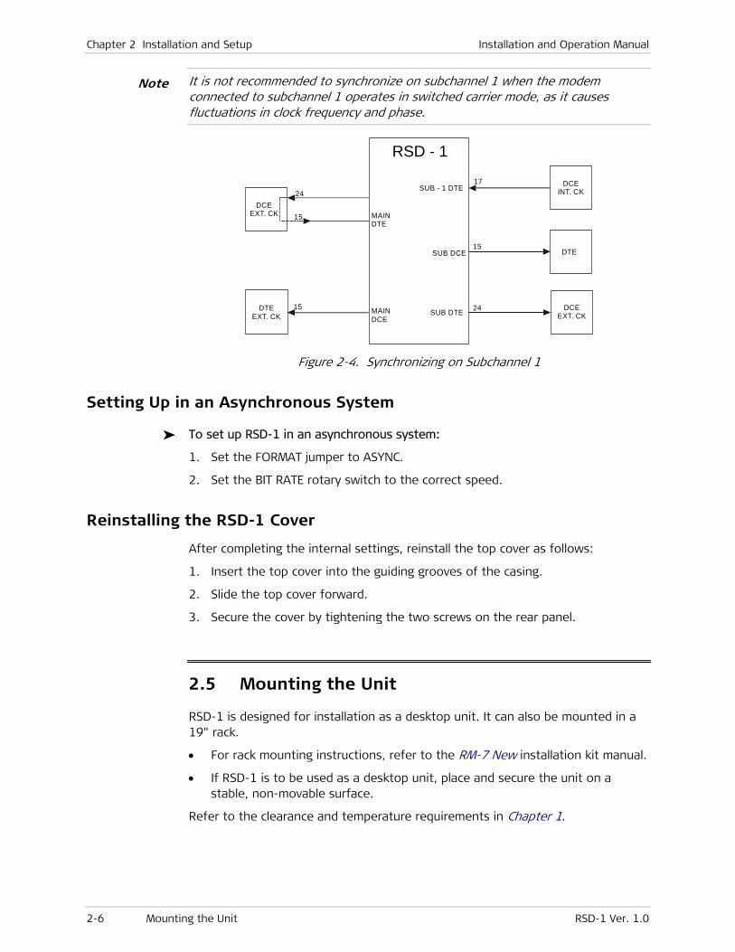
Synchronizing on Subchannel 1
To synchronize RSD-1 on subchannel 1:
1. Set the RSD-1 BIT RATE rotary switch to position 7.
2. Set the DCE attached to the main channel to external clock.
3. Set the DCEs attached to the subchannels to external clock.
4. Set the modem attached to subchannel 1 to internal clock.
Chapter 2 Installation and Setup Installation and Operation Manual
2-6 Mounting the Unit RSD-1 Ver. 1.0
It is not recommended to synchronize on subchannel 1 when the modem connected to subchannel 1 operates in switched carrier mode, as it causes fluctuations in clock frequency and phase.
DTEEXT. CK
15
15
15
1724
24
DCEEXT. CK
DCEINT. CK
DCEEXT. CK
MAINDTE
DTE
SUB - 1 DTE
SUB DTE
SUB DCE
RSD - 1
MAINDCE
Figure 2-4. Synchronizing on Subchannel 1
Setting Up in an Asynchronous System
To set up RSD-1 in an asynchronous system:
1. Set the FORMAT jumper to ASYNC.
2. Set the BIT RATE rotary switch to the correct speed.
Reinstalling the RSD-1 Cover
After completing the internal settings, reinstall the top cover as follows:
1. Insert the top cover into the guiding grooves of the casing.
2. Slide the top cover forward.
3. Secure the cover by tightening the two screws on the rear panel.
2.5 Mounting the Unit
RSD-1 is designed for installation as a desktop unit. It can also be mounted in a 19" rack.
• For rack mounting instructions, refer to the RM-7 New installation kit manual.
• If RSD-1 is to be used as a desktop unit, place and secure the unit on a stable, non-movable surface.
Refer to the clearance and temperature requirements in Chapter 1.
Note
Installation and Operation Manual Chapter 2 Installation and Setup
RSD-1 Ver. 1.0 Interfaces and Connections 2-7
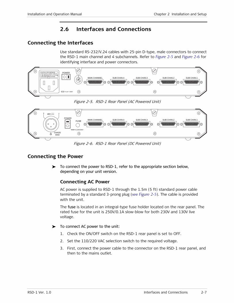
2.6 Interfaces and Connections
Connecting the Interfaces
Use standard RS-232/V.24 cables with 25-pin D-type, male connectors to connect the RSD-1 main channel and 4 subchannels. Refer to Figure 2-5 and Figure 2-6 for identifying interface and power connectors.
POWER
MAIN CHANNEL SUB CHAN.4 SUB CHAN.3 SUB CHAN.2 SUB CHAN.1
0.1A T 250V
Figure 2-5. RSD-1 Rear Panel (AC Powered Unit)
MAIN CHANNEL
CHASSGND
+ 48V
SUB CHAN.4 SUB CHAN.3 SUB CHAN.2 SUB CHAN.1POWER
FUSE
0.125A/250V
Figure 2-6. RSD-1 Rear Panel (DC Powered Unit)
Connecting the Power
To connect the power to RSD-1, refer to the appropriate section below, depending on your unit version.
Connecting AC Power
AC power is supplied to RSD-1 through the 1.5m (5 ft) standard power cable terminated by a standard 3-prong plug (see Figure 2-5). The cable is provided with the unit.
The fuse is located in an integral-type fuse holder located on the rear panel. The rated fuse for the unit is 250V/0.1A slow-blow for both 230V and 130V live voltage.
To connect AC power to the unit:
1. Check the ON/OFF switch on the RSD-1 rear panel is set to OFF.
2. Set the 110/220 VAC selection switch to the required voltage.
3. First, connect the power cable to the connector on the RSD-1 rear panel, and then to the mains outlet.
Chapter 2 Installation and Setup Installation and Operation Manual
2-8 Interfaces and Connections RSD-1 Ver. 1.0
Connecting DC Power
To connect DC power:
Refer to the DC power supply connection supplement for instructions how to wire the DC cables. The DC supplement is provided on the technical documentation CD supplied with the unit.
RSD-1 Ver. 1.0 Front Panel Controls and Indicators 3-1
Chapter 3
Operation
This chapter describes RSD-1 controls and indicators and their functions, and explains the operating procedures.
Installation procedures given in Chapter 2 must be completed before attempting to operate RSD-1.
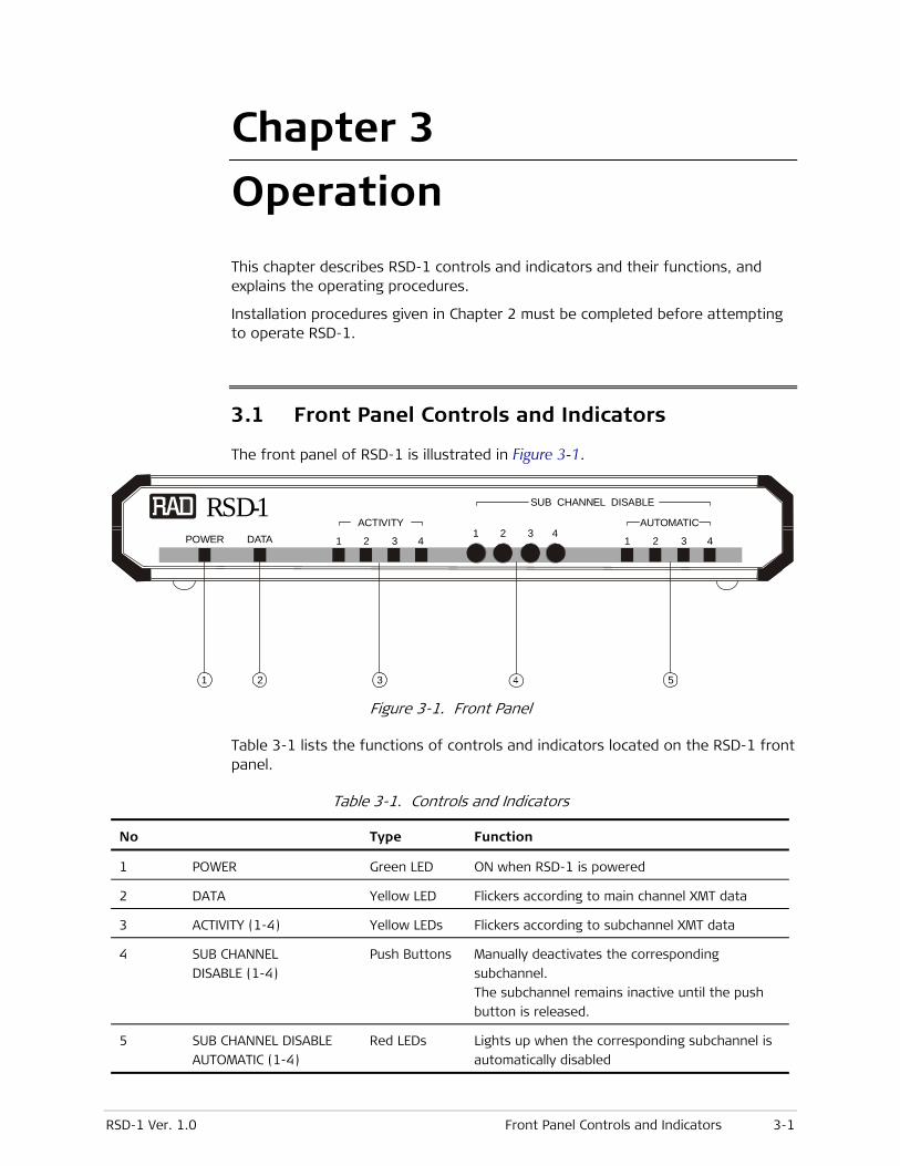
3.1 Front Panel Controls and Indicators
The front panel of RSD-1 is illustrated in Figure 3-1.
POWER DATA
RSD-1AUTOMATICACTIVITY
SUB CHANNEL DISABLE
1 2 311 22 33 44
4
1 2 3 5
Figure 3-1. Front Panel
Table 3-1 lists the functions of controls and indicators located on the RSD-1 front panel.
Table 3-1. Controls and Indicators
No Type Function
1 POWER Green LED ON when RSD-1 is powered
2 DATA Yellow LED Flickers according to main channel XMT data
3 ACTIVITY (1-4) Yellow LEDs Flickers according to subchannel XMT data
4 SUB CHANNEL
DISABLE (1-4)
Push Buttons Manually deactivates the corresponding
subchannel.
The subchannel remains inactive until the push
button is released.
5 SUB CHANNEL DISABLE
AUTOMATIC (1-4)
Red LEDs Lights up when the corresponding subchannel is
automatically disabled
Chapter 3 Operation Installation and Operation Manual
3-2 Operating RSD-1 RSD-1 Ver. 1.0
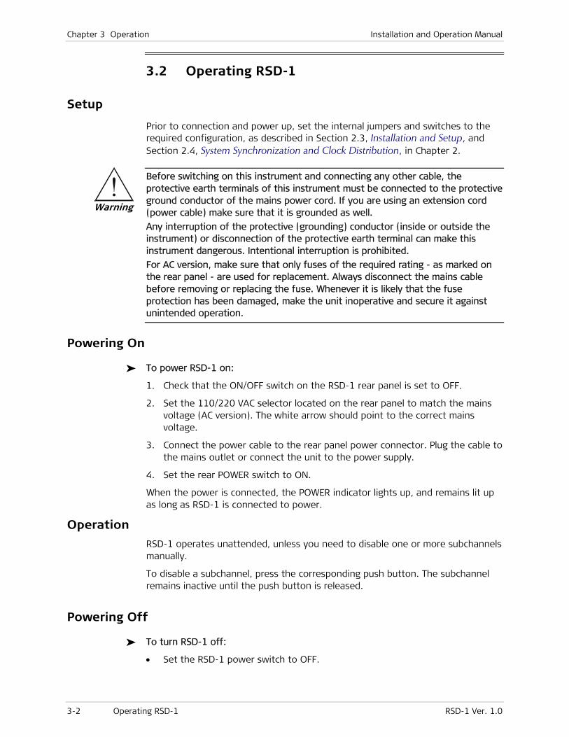
3.2 Operating RSD-1
Setup
Prior to connection and power up, set the internal jumpers and switches to the required configuration, as described in Section 2.3, Installation and Setup, and Section 2.4, System Synchronization and Clock Distribution, in Chapter 2.
Before switching on this instrument and connecting any other cable, the protective earth terminals of this instrument must be connected to the protective ground conductor of the mains power cord. If you are using an extension cord (power cable) make sure that it is grounded as well.
Any interruption of the protective (grounding) conductor (inside or outside the instrument) or disconnection of the protective earth terminal can make this instrument dangerous. Intentional interruption is prohibited.
For AC version, make sure that only fuses of the required rating - as marked on the rear panel - are used for replacement. Always disconnect the mains cable before removing or replacing the fuse. Whenever it is likely that the fuse protection has been damaged, make the unit inoperative and secure it against unintended operation.
Powering On
To power RSD-1 on:
1. Check that the ON/OFF switch on the RSD-1 rear panel is set to OFF.
2. Set the 110/220 VAC selector located on the rear panel to match the mains voltage (AC version). The white arrow should point to the correct mains voltage.
3. Connect the power cable to the rear panel power connector. Plug the cable to the mains outlet or connect the unit to the power supply.
4. Set the rear POWER switch to ON.
When the power is connected, the POWER indicator lights up, and remains lit up as long as RSD-1 is connected to power.
Operation
RSD-1 operates unattended, unless you need to disable one or more subchannels manually.
To disable a subchannel, press the corresponding push button. The subchannel remains inactive until the push button is released.
Powering Off
To turn RSD-1 off:
• Set the RSD-1 power switch to OFF.
Warning
RSD-1 Ver. 1.0 Detecting Errors 4-1
Chapter 4
Troubleshooting and Diagnostics
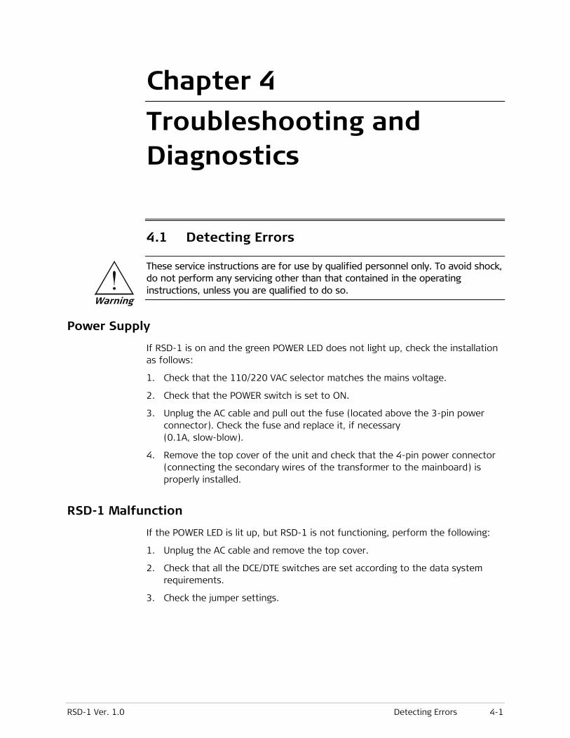
4.1 Detecting Errors
These service instructions are for use by qualified personnel only. To avoid shock, do not perform any servicing other than that contained in the operating instructions, unless you are qualified to do so.
Power Supply
If RSD-1 is on and the green POWER LED does not light up, check the installation as follows:
1. Check that the 110/220 VAC selector matches the mains voltage.
2. Check that the POWER switch is set to ON.
3. Unplug the AC cable and pull out the fuse (located above the 3-pin power connector). Check the fuse and replace it, if necessary (0.1A, slow-blow).
4. Remove the top cover of the unit and check that the 4-pin power connector (connecting the secondary wires of the transformer to the mainboard) is properly installed.
RSD-1 Malfunction
If the POWER LED is lit up, but RSD-1 is not functioning, perform the following:
1. Unplug the AC cable and remove the top cover.
2. Check that all the DCE/DTE switches are set according to the data system requirements.
3. Check the jumper settings.
Warning
Chapter 4 Troubleshooting and Diagnostics Installation and Operation Manual
4-2 Detecting Errors RSD-1 Ver. 1.0
24 Raoul Wallenberg Street, Tel Aviv 69719, Israel
Tel: +972-3-6458181, Fax +972-3-6483331, +972-3-6498250
E-mail: [email protected], Web site: http://www.rad.com
Customer Response Form
RAD Data Communications would like your help in improving its product documentation. Please complete and return this form by mail or by fax or send us an e-mail with your comments.
Thank you for your assistance!
Manual Name: RSD-1 Ver. 1.0
Publication Number: 557-200-03/08
Please grade the manual according to the following factors:
Excellent Good Fair Poor Very Poor
Installation instructions
Operating instructions
Manual organization
Illustrations
The manual as a whole
What did you like about the manual?

Error Report
Type of error(s) or problem(s):
Incompatibility with product
Difficulty in understanding text
Regulatory information (Safety, Compliance, Warnings, etc.)
Difficulty in finding needed information
Missing information
Illogical flow of information
Style (spelling, grammar, references, etc.)
Appearance
Other
Please list the exact page numbers with the error(s), detail the errors you found (information missing, unclear or inadequately explained, etc.) and attach the page to your fax, if necessary.
Please add any comments or suggestions you may have.
You are: Distributor
End user
VAR
Other
Who is your distributor?
Your name and company:
Job title:
Address:
Direct telephone number and extension:
Fax number:
E-mail:


Publication No. 557-200-03/08
International Headquarters 24 Raoul Wallenberg Street
Tel Aviv 69719, Israel
Tel. 972-3-6458181
Fax 972-3-6498250, 6474436
E-mail [email protected]
North America Headquarters 900 Corporate Drive
Mahwah, NJ 07430, USA
Tel. 201-5291100 Toll free 1-800-4447234
Fax 201-5295777
E-mail [email protected]
www.rad.com The Access Company