Embed Size (px)
Citation preview
Data
She
et |
Vers
ion
05.0
1
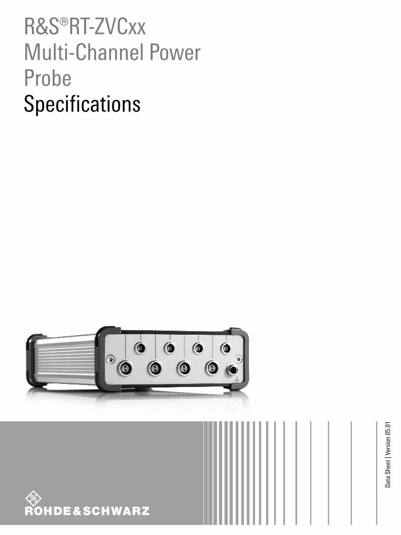
R&S®RT-ZVCxx Multi-Channel Power ProbeSpecifications
RT-ZVCxx_dat-sw_en_5214-7058-22_v0501_Cover.indd 1 06.06.2018 08:05:49
Version 05.01, June 2018
2 Rohde & Schwarz R&S®RT-ZVCxx Multi-Channel Power Probe
CONTENTS Definitions ....................................................................................................................................................................... 3
Probe characteristics ...................................................................................................................................................... 4
Voltmeter of the R&S®RT-ZVC02/02A/04/04A ................................................................................................................................... 4
Amperemeter of the R&S®RT-ZVC02/-ZVC04 ................................................................................................................................... 5
Amperemeter of the R&S®RT-ZVC02A/-ZVC04A ............................................................................................................................... 7
Digital backend of the R&S®RT-ZVC02/02A/04/04A ........................................................................................................................ 10
R&S®CMWrun interface ................................................................................................................................................................... 11
R&S®RTO2000, R&S®RTE interface (R&S®RT-ZVC02/-ZVC04 only) .............................................................................................. 11
Vertical system ............................................................................................................................................................................. 11
Horizontal system......................................................................................................................................................................... 11
Acquisition system ....................................................................................................................................................................... 12
Trigger system ............................................................................................................................................................................. 12
Prerequisites ................................................................................................................................................................................ 12
Features ....................................................................................................................................................................................... 12
General data of the R&S®RT-ZVC02/02A/04/04A ........................................................................................................ 13
Ordering information .................................................................................................................................................... 14
Version 05.01, June 2018
Rohde & Schwarz R&S®RT-ZVCxx Multi-Channel Power Probe 3
Definitions General
Product data applies under the following conditions:
Three hours storage at ambient temperature followed by 30 minutes warm-up operation
Specified environmental conditions met
Recommended calibration interval adhered to
All internal automatic adjustments performed, if applicable
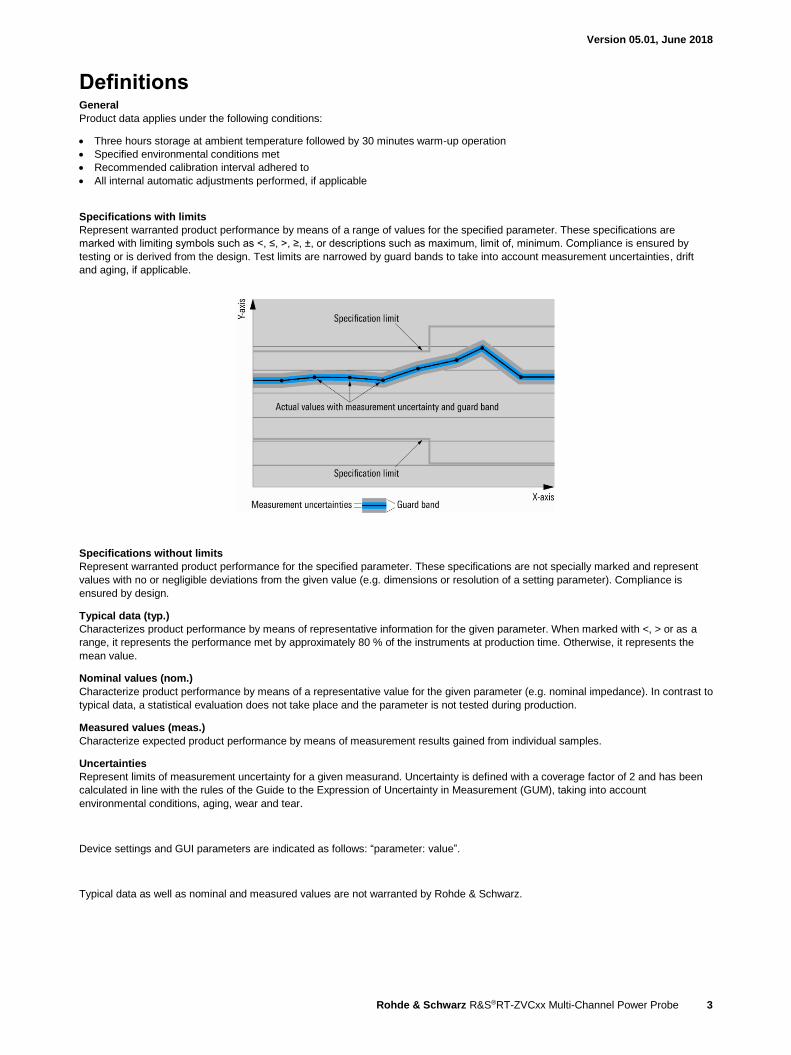
Specifications with limits
Represent warranted product performance by means of a range of values for the specified parameter. These specifications are
marked with limiting symbols such as <, ≤, >, ≥, ±, or descriptions such as maximum, limit of, minimum. Compliance is ensured by
testing or is derived from the design. Test limits are narrowed by guard bands to take into account measurement uncertainties, drift
and aging, if applicable.
Specifications without limits
Represent warranted product performance for the specified parameter. These specifications are not specially marked and represent
values with no or negligible deviations from the given value (e.g. dimensions or resolution of a setting parameter). Compliance is
ensured by design.
Typical data (typ.)
Characterizes product performance by means of representative information for the given parameter. When marked with <, > or as a
range, it represents the performance met by approximately 80 % of the instruments at production time. Otherwise, it represents the
mean value.
Nominal values (nom.)
Characterize product performance by means of a representative value for the given parameter (e.g. nominal impedance). In contrast to
typical data, a statistical evaluation does not take place and the parameter is not tested during production.
Measured values (meas.)
Characterize expected product performance by means of measurement results gained from individual samples.
Uncertainties
Represent limits of measurement uncertainty for a given measurand. Uncertainty is defined with a coverage factor of 2 and has been
calculated in line with the rules of the Guide to the Expression of Uncertainty in Measurement (GUM), taking into account
environmental conditions, aging, wear and tear.
Device settings and GUI parameters are indicated as follows: “parameter: value”.
Typical data as well as nominal and measured values are not warranted by Rohde & Schwarz.
Version 05.01, June 2018
4 Rohde & Schwarz R&S®RT-ZVCxx Multi-Channel Power Probe
Probe characteristics
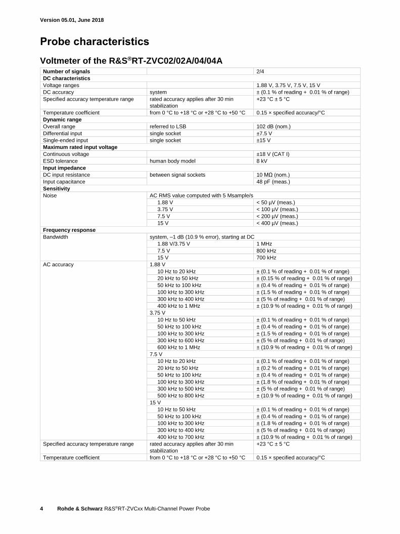
Voltmeter of the R&S®RT-ZVC02/02A/04/04A Number of signals 2/4
DC characteristics
Voltage ranges 1.88 V, 3.75 V, 7.5 V, 15 V
DC accuracy system ± (0.1 % of reading + 0.01 % of range)
Specified accuracy temperature range rated accuracy applies after 30 min
stabilization
+23 °C ± 5 °C
Temperature coefficient from 0 °C to +18 °C or +28 °C to +50 °C 0.15 × specified accuracy/°C
Dynamic range
Overall range referred to LSB 102 dB (nom.)
Differential input single socket ±7.5 V
Single-ended input single socket ±15 V
Maximum rated input voltage
Continuous voltage ±18 V (CAT I)
ESD tolerance human body model 8 kV
Input impedance
DC input resistance between signal sockets 10 MΩ (nom.)
Input capacitance 48 pF (meas.)
Sensitivity
Noise AC RMS value computed with 5 Msample/s
1.88 V < 50 µV (meas.)
3.75 V < 100 µV (meas.)
7.5 V < 200 µV (meas.)
15 V < 400 µV (meas.)
Frequency response
Bandwidth system, –1 dB (10.9 % error), starting at DC
1.88 V/3.75 V 1 MHz
7.5 V 800 kHz
15 V 700 kHz
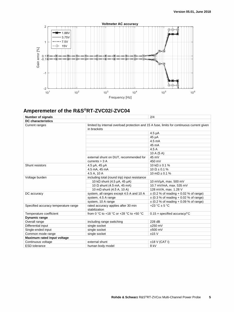
AC accuracy 1.88 V
10 Hz to 20 kHz ± (0.1 % of reading + 0.01 % of range)
20 kHz to 50 kHz ± (0.15 % of reading + 0.01 % of range)
50 kHz to 100 kHz ± (0.4 % of reading + 0.01 % of range)
100 kHz to 300 kHz ± (1.5 % of reading + 0.01 % of range)
300 kHz to 400 kHz ± (5 % of reading + 0.01 % of range)
400 kHz to 1 MHz ± (10.9 % of reading + 0.01 % of range)
3.75 V
10 Hz to 50 kHz ± (0.1 % of reading + 0.01 % of range)
50 kHz to 100 kHz ± (0.4 % of reading + 0.01 % of range)
100 kHz to 300 kHz ± (1.5 % of reading + 0.01 % of range)
300 kHz to 600 kHz ± (5 % of reading + 0.01 % of range)
600 kHz to 1 MHz ± (10.9 % of reading + 0.01 % of range)
7.5 V
10 Hz to 20 kHz ± (0.1 % of reading + 0.01 % of range)
20 kHz to 50 kHz ± (0.2 % of reading + 0.01 % of range)
50 kHz to 100 kHz ± (0.4 % of reading + 0.01 % of range)
100 kHz to 300 kHz ± (1.8 % of reading + 0.01 % of range)
300 kHz to 500 kHz ± (5 % of reading + 0.01 % of range)
500 kHz to 800 kHz ± (10.9 % of reading + 0.01 % of range)
15 V
10 Hz to 50 kHz ± (0.1 % of reading + 0.01 % of range)
50 kHz to 100 kHz ± (0.4 % of reading + 0.01 % of range)
100 kHz to 300 kHz ± (1.8 % of reading + 0.01 % of range)
300 kHz to 400 kHz ± (5 % of reading + 0.01 % of range)
400 kHz to 700 kHz ± (10.9 % of reading + 0.01 % of range)
Specified accuracy temperature range rated accuracy applies after 30 min
stabilization
+23 °C ± 5 °C
Temperature coefficient from 0 °C to +18 °C or +28 °C to +50 °C 0.15 × specified accuracy/°C
Version 05.01, June 2018
Rohde & Schwarz R&S®RT-ZVCxx Multi-Channel Power Probe 5
Amperemeter of the R&S®RT-ZVC02/-ZVC04 Number of signals 2/4
DC characteristics
Current ranges limited by internal overload protection and 15 A fuse, limits for continuous current given
in brackets
4.5 µA
45 µA
4.5 mA
45 mA
4.5 A
10 A (5 A)
external shunt on DUT, recommended for
currents > 3 A
45 mV
450 mV
Shunt resistors 4.5 µA, 45 µA 10 kΩ ± 0.1 %
4.5 mA, 45 mA 10 Ω ± 0.1 %
4.5 A, 10 A 10 mΩ ± 0.1 %
Voltage burden including total (round trip) input resistance
10 kΩ shunt (4.5 µA, 45 µA) 10 mV/µA, max. 500 mV
10 Ω shunt (4.5 mA, 45 mA) 10.7 mV/mA, max. 535 mV
10 mΩ shunt (4.5 A, 10 A) 128 mV/A, max. 1.28 V
DC accuracy system, all ranges except 4.5 A and 10 A ± (0.2 % of reading + 0.02 % of range)
system, 4.5 A range ± (0.3 % of reading + 0.02 % of range)
system, 10 A range ± (0.2 % of reading + 0.09 % of range)
Specified accuracy temperature range rated accuracy applies after 30 min
stabilization
+23 °C ± 5 °C
Temperature coefficient from 0 °C to +18 °C or +28 °C to +50 °C 0.15 × specified accuracy/°C
Dynamic range
Overall range including range switching 228 dB
Differential input single socket ±250 mV
Single-ended input single socket ±500 mV
Common mode range single socket ±15 V
Maximum rated input voltage
Continuous voltage external shunt ±18 V (CAT I)
ESD tolerance human body model 8 kV
Version 05.01, June 2018
6 Rohde & Schwarz R&S®RT-ZVCxx Multi-Channel Power Probe
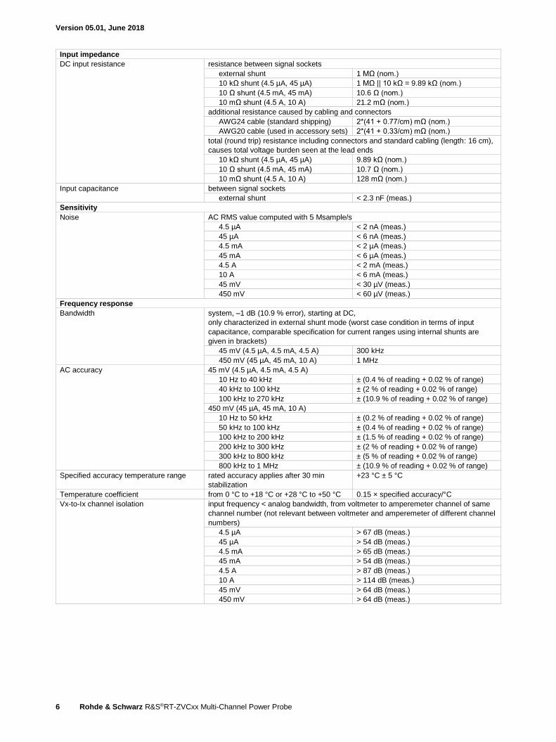
Input impedance
DC input resistance resistance between signal sockets
external shunt 1 MΩ (nom.)
10 kΩ shunt (4.5 µA, 45 µA) 1 MΩ || 10 kΩ = 9.89 kΩ (nom.)
10 Ω shunt (4.5 mA, 45 mA) 10.6 Ω (nom.)
10 mΩ shunt (4.5 A, 10 A) 21.2 mΩ (nom.)
additional resistance caused by cabling and connectors
AWG24 cable (standard shipping) 2*(41 + 0.77/cm) mΩ (nom.)
AWG20 cable (used in accessory sets) 2*(41 + 0.33/cm) mΩ (nom.)
total (round trip) resistance including connectors and standard cabling (length: 16 cm),
causes total voltage burden seen at the lead ends
10 kΩ shunt (4.5 µA, 45 µA) 9.89 kΩ (nom.)
10 Ω shunt (4.5 mA, 45 mA) 10.7 Ω (nom.)
10 mΩ shunt (4.5 A, 10 A) 128 mΩ (nom.)
Input capacitance between signal sockets
external shunt < 2.3 nF (meas.)
Sensitivity
Noise AC RMS value computed with 5 Msample/s
4.5 µA < 2 nA (meas.)
45 µA < 6 nA (meas.)
4.5 mA < 2 µA (meas.)
45 mA < 6 µA (meas.)
4.5 A < 2 mA (meas.)
10 A < 6 mA (meas.)
45 mV < 30 µV (meas.)
450 mV < 60 µV (meas.)
Frequency response
Bandwidth system, –1 dB (10.9 % error), starting at DC,
only characterized in external shunt mode (worst case condition in terms of input
capacitance, comparable specification for current ranges using internal shunts are
given in brackets)
45 mV (4.5 µA, 4.5 mA, 4.5 A) 300 kHz
450 mV (45 µA, 45 mA, 10 A) 1 MHz
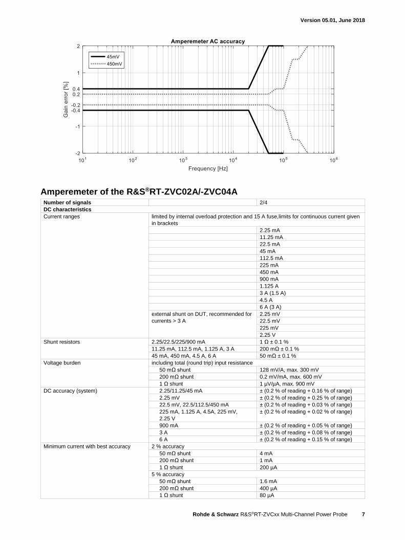
AC accuracy 45 mV (4.5 µA, 4.5 mA, 4.5 A)
10 Hz to 40 kHz ± (0.4 % of reading + 0.02 % of range)
40 kHz to 100 kHz ± (2 % of reading + 0.02 % of range)
100 kHz to 270 kHz ± (10.9 % of reading + 0.02 % of range)
450 mV (45 µA, 45 mA, 10 A)
10 Hz to 50 kHz ± (0.2 % of reading + 0.02 % of range)
50 kHz to 100 kHz ± (0.4 % of reading + 0.02 % of range)
100 kHz to 200 kHz ± (1.5 % of reading + 0.02 % of range)
200 kHz to 300 kHz ± (2 % of reading + 0.02 % of range)
300 kHz to 800 kHz ± (5 % of reading + 0.02 % of range)
800 kHz to 1 MHz ± (10.9 % of reading + 0.02 % of range)
Specified accuracy temperature range rated accuracy applies after 30 min
stabilization
+23 °C ± 5 °C
Temperature coefficient from 0 °C to +18 °C or +28 °C to +50 °C 0.15 × specified accuracy/°C
Vx-to-Ix channel isolation input frequency < analog bandwidth, from voltmeter to amperemeter channel of same
channel number (not relevant between voltmeter and amperemeter of different channel
numbers)
4.5 µA > 67 dB (meas.)
45 µA > 54 dB (meas.)
4.5 mA > 65 dB (meas.)
45 mA > 54 dB (meas.)
4.5 A > 87 dB (meas.)
10 A > 114 dB (meas.)
45 mV > 64 dB (meas.)
450 mV > 64 dB (meas.)
Version 05.01, June 2018
Rohde & Schwarz R&S®RT-ZVCxx Multi-Channel Power Probe 7
Amperemeter of the R&S®RT-ZVC02A/-ZVC04A Number of signals 2/4
DC characteristics
Current ranges limited by internal overload protection and 15 A fuse,limits for continuous current given
in brackets
2.25 mA
11.25 mA
22.5 mA
45 mA
112.5 mA
225 mA
450 mA
900 mA
1.125 A
3 A (1.5 A)
4.5 A
6 A (3 A)
external shunt on DUT, recommended for
currents > 3 A
2.25 mV
22.5 mV
225 mV
2.25 V
Shunt resistors 2.25/22.5/225/900 mA 1 Ω ± 0.1 %
11.25 mA, 112.5 mA, 1.125 A, 3 A 200 mΩ ± 0.1 %
45 mA, 450 mA, 4.5 A, 6 A 50 mΩ ± 0.1 %
Voltage burden including total (round trip) input resistance
50 mΩ shunt 128 mV/A, max. 300 mV
200 mΩ shunt 0.2 mV/mA, max. 600 mV
1 Ω shunt 1 µV/µA, max. 900 mV
DC accuracy (system) 2.25/11.25/45 mA ± (0.2 % of reading + 0.16 % of range)
2.25 mV ± (0.2 % of reading + 0.25 % of range)
22.5 mV, 22.5/112.5/450 mA ± (0.2 % of reading + 0.03 % of range)
225 mA, 1.125 A, 4.5A, 225 mV,
2.25 V
± (0.2 % of reading + 0.02 % of range)
900 mA ± (0.2 % of reading + 0.05 % of range)
3 A ± (0.2 % of reading + 0.08 % of range)
6 A ± (0.2 % of reading + 0.15 % of range)
Minimum current with best accuracy 2 % accuracy
50 mΩ shunt 4 mA
200 mΩ shunt 1 mA
1 Ω shunt 200 µA
5 % accuracy
50 mΩ shunt 1.6 mA
200 mΩ shunt 400 µA
1 Ω shunt 80 µA
Version 05.01, June 2018
8 Rohde & Schwarz R&S®RT-ZVCxx Multi-Channel Power Probe
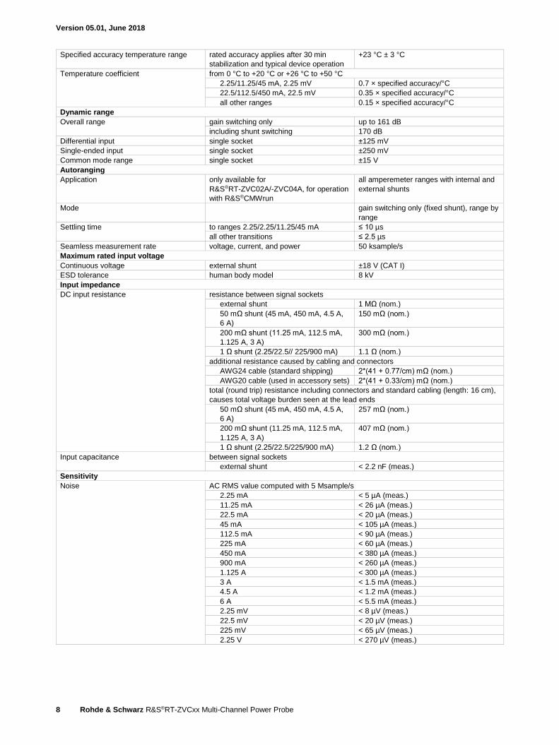
Specified accuracy temperature range rated accuracy applies after 30 min
stabilization and typical device operation
+23 °C ± 3 °C
Temperature coefficient from 0 °C to +20 °C or +26 °C to +50 °C
2.25/11.25/45 mA, 2.25 mV 0.7 × specified accuracy/°C
22.5/112.5/450 mA, 22.5 mV 0.35 × specified accuracy/°C
all other ranges 0.15 × specified accuracy/°C
Dynamic range
Overall range gain switching only up to 161 dB
including shunt switching 170 dB
Differential input single socket ±125 mV
Single-ended input single socket ±250 mV
Common mode range single socket ±15 V
Autoranging
Application only available for
R&S®RT-ZVC02A/-ZVC04A, for operation
with R&S®CMWrun
all amperemeter ranges with internal and
external shunts
Mode gain switching only (fixed shunt), range by
range
Settling time to ranges 2.25/2.25/11.25/45 mA ≤ 10 µs
all other transitions ≤ 2.5 µs
Seamless measurement rate voltage, current, and power 50 ksample/s
Maximum rated input voltage
Continuous voltage external shunt ±18 V (CAT I)
ESD tolerance human body model 8 kV
Input impedance
DC input resistance resistance between signal sockets
external shunt 1 MΩ (nom.)
50 mΩ shunt (45 mA, 450 mA, 4.5 A,
6 A)
150 mΩ (nom.)
200 mΩ shunt (11.25 mA, 112.5 mA,
1.125 A, 3 A)
300 mΩ (nom.)
1 Ω shunt (2.25/22.5// 225/900 mA) 1.1 Ω (nom.)
additional resistance caused by cabling and connectors
AWG24 cable (standard shipping) 2*(41 + 0.77/cm) mΩ (nom.)
AWG20 cable (used in accessory sets) 2*(41 + 0.33/cm) mΩ (nom.)
total (round trip) resistance including connectors and standard cabling (length: 16 cm),
causes total voltage burden seen at the lead ends
50 mΩ shunt (45 mA, 450 mA, 4.5 A,
6 A)
257 mΩ (nom.)
200 mΩ shunt (11.25 mA, 112.5 mA,
1.125 A, 3 A)
407 mΩ (nom.)
1 Ω shunt (2.25/22.5/225/900 mA) 1.2 Ω (nom.)
Input capacitance between signal sockets
external shunt < 2.2 nF (meas.)
Sensitivity
Noise AC RMS value computed with 5 Msample/s
2.25 mA < 5 µA (meas.)
11.25 mA < 26 µA (meas.)
22.5 mA < 20 µA (meas.)
45 mA < 105 µA (meas.)
112.5 mA < 90 µA (meas.)
225 mA < 60 µA (meas.)
450 mA < 380 µA (meas.)
900 mA < 260 µA (meas.)
1.125 A < 300 µA (meas.)
3 A < 1.5 mA (meas.)
4.5 A < 1.2 mA (meas.)
6 A < 5.5 mA (meas.)
2.25 mV < 8 µV (meas.)
22.5 mV < 20 µV (meas.)
225 mV < 65 µV (meas.)
2.25 V < 270 µV (meas.)
Version 05.01, June 2018
Rohde & Schwarz R&S®RT-ZVCxx Multi-Channel Power Probe 9
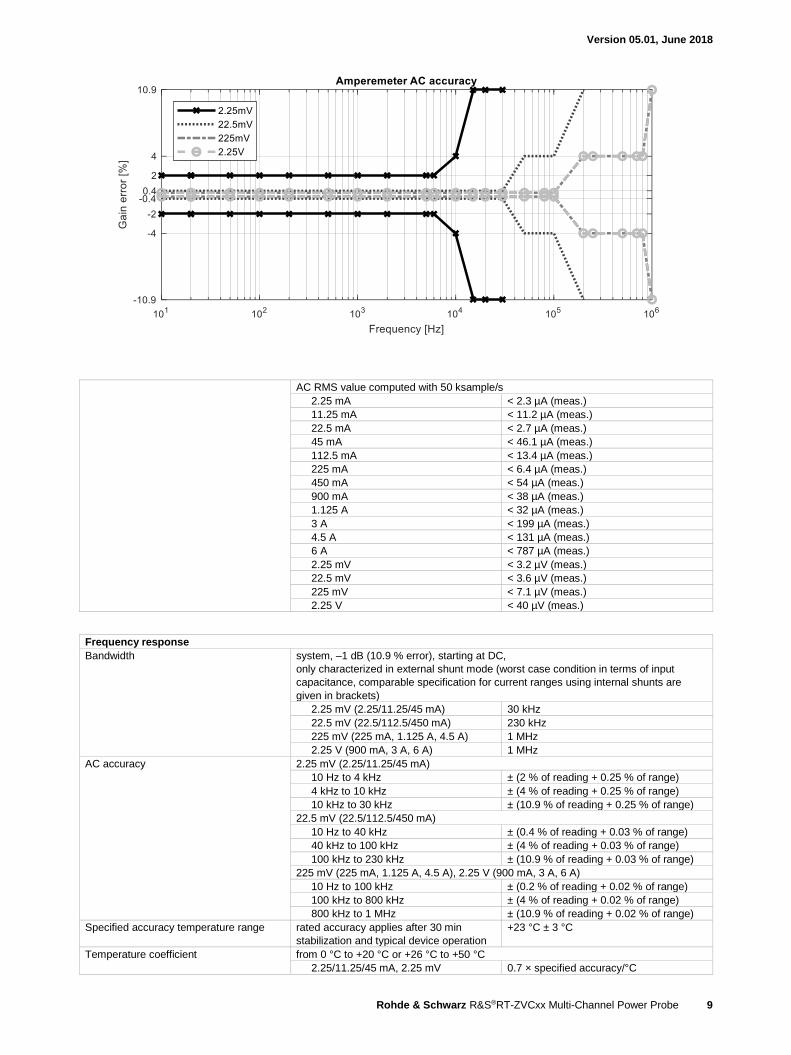
AC RMS value computed with 50 ksample/s
2.25 mA < 2.3 µA (meas.)
11.25 mA < 11.2 µA (meas.)
22.5 mA < 2.7 µA (meas.)
45 mA < 46.1 µA (meas.)
112.5 mA < 13.4 µA (meas.)
225 mA < 6.4 µA (meas.)
450 mA < 54 µA (meas.)
900 mA < 38 µA (meas.)
1.125 A < 32 µA (meas.)
3 A < 199 µA (meas.)
4.5 A < 131 µA (meas.)
6 A < 787 µA (meas.)
2.25 mV < 3.2 µV (meas.)
22.5 mV < 3.6 µV (meas.)
225 mV < 7.1 µV (meas.)
2.25 V < 40 µV (meas.)
Frequency response
Bandwidth system, –1 dB (10.9 % error), starting at DC,
only characterized in external shunt mode (worst case condition in terms of input
capacitance, comparable specification for current ranges using internal shunts are
given in brackets)
2.25 mV (2.25/11.25/45 mA) 30 kHz
22.5 mV (22.5/112.5/450 mA) 230 kHz
225 mV (225 mA, 1.125 A, 4.5 A) 1 MHz
2.25 V (900 mA, 3 A, 6 A) 1 MHz
AC accuracy 2.25 mV (2.25/11.25/45 mA)
10 Hz to 4 kHz ± (2 % of reading + 0.25 % of range)
4 kHz to 10 kHz ± (4 % of reading + 0.25 % of range)
10 kHz to 30 kHz ± (10.9 % of reading + 0.25 % of range)
22.5 mV (22.5/112.5/450 mA)
10 Hz to 40 kHz ± (0.4 % of reading + 0.03 % of range)
40 kHz to 100 kHz ± (4 % of reading + 0.03 % of range)
100 kHz to 230 kHz ± (10.9 % of reading + 0.03 % of range)
225 mV (225 mA, 1.125 A, 4.5 A), 2.25 V (900 mA, 3 A, 6 A)
10 Hz to 100 kHz ± (0.2 % of reading + 0.02 % of range)
100 kHz to 800 kHz ± (4 % of reading + 0.02 % of range)
800 kHz to 1 MHz ± (10.9 % of reading + 0.02 % of range)
Specified accuracy temperature range rated accuracy applies after 30 min
stabilization and typical device operation
+23 °C ± 3 °C
Temperature coefficient from 0 °C to +20 °C or +26 °C to +50 °C
2.25/11.25/45 mA, 2.25 mV 0.7 × specified accuracy/°C
Version 05.01, June 2018
10 Rohde & Schwarz R&S®RT-ZVCxx Multi-Channel Power Probe
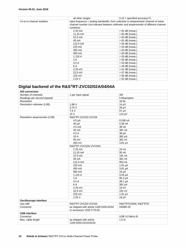
all other ranges 0.15 × specified accuracy/°C
Vx-to-Ix channel isolation input frequency < analog bandwidth, from voltmeter to amperemeter channel of same
channel number (not relevant between voltmeter and amperemeter of different channel
numbers)
2.25 mA > 81 dB (meas.)
11.25 mA > 82 dB (meas.)
22.5 mA > 63 dB (meas.)
45 mA > 81 dB (meas.)
112.5 mA > 64 dB (meas.)
225 mA > 53 dB (meas.)
450 mA > 63 dB (meas.)
900 mA > 50 dB (meas.)
1.125 A > 53 dB (meas.)
3 A > 50 dB (meas.)
4.5 A > 53 dB (meas.)
6 A > 49 dB (meas.)
2.25 mV > 61 dB (meas.)
22.5 mV > 57 dB (meas.)
225 mV > 55 dB (meas.)
2.25 V > 52 dB (meas.)
Digital backend of the R&S®RT-ZVC02/02A/04/04A A/D conversion
Number of channels 1 per input signal 4/8
Readings per second (speed) 5 Msample/s
Resolution 18 bit
Resolution voltmeter (LSB) 1.88 V 14 µV
3.75 V 28 µV
7.5 V 57 µV
15 V 114 µV
Resolution amperemeter (LSB) R&S®RT-ZVC02/-ZVC04
4.5 µA 0.038 nA
45 µA 0.38 nA
4.5 mA 38 nA
45 mA 381 nA
4.5 A 38 µA
10 A 381 µA
45 mV 381 nV
450 mV 3.81 µV
R&S®RT-ZVC02A/-ZVC04A
2.25 mA 19 nA
11.25 mA 95 nA
22.5 mA 191 nA
45 mA 381 nA
112.5 mA 954 nA
225 mA 1.91 µA
450 mA 3.81 µA
900 mA 19 µA
1.125 A 9.54 µA
3 A 95.4 µA
4.5 A 38.1 µA
6 A 381 µA
2.25 mV 19 nV
22.5 mV 191 nV
225 mV 1.91 µV
2.25 V 19 µV
Oscilloscope interface
Use with R&S®RT-ZVC02/-ZVC04 R&S®RTO2000, R&S®RTE
Connector as shipped with article 1326.0259.02/04
or accessory 1333.1770.02
HDMR-29
USB interface
Connector USB 3.0 Micro B
Max. cable length as shipped with article
1326.0259.22/24/32/34
1.5 m
Version 05.01, June 2018
Rohde & Schwarz R&S®RT-ZVCxx Multi-Channel Power Probe 11
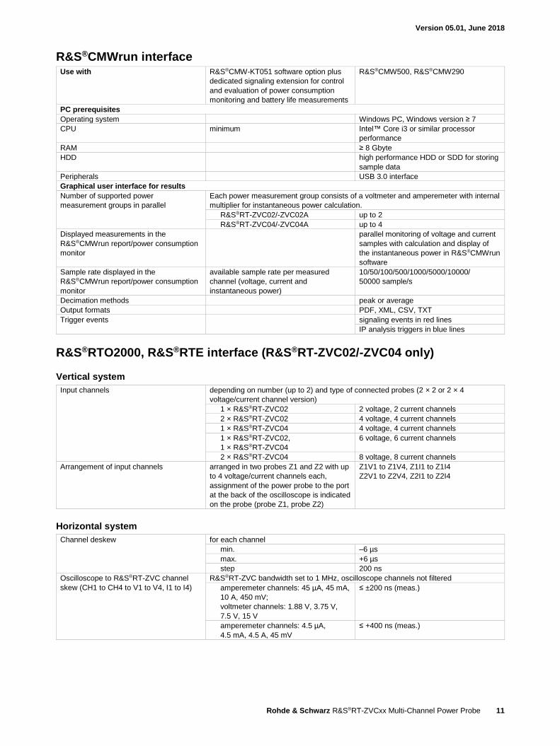
R&S®CMWrun interface Use with R&S®CMW-KT051 software option plus
dedicated signaling extension for control
and evaluation of power consumption
monitoring and battery life measurements
R&S®CMW500, R&S®CMW290
PC prerequisites
Operating system Windows PC, Windows version ≥ 7
CPU minimum Intel™ Core i3 or similar processor
performance
RAM ≥ 8 Gbyte
HDD high performance HDD or SDD for storing
sample data
Peripherals USB 3.0 interface
Graphical user interface for results
Number of supported power
measurement groups in parallel
Each power measurement group consists of a voltmeter and amperemeter with internal
multiplier for instantaneous power calculation.
R&S®RT-ZVC02/-ZVC02A up to 2
R&S®RT-ZVC04/-ZVC04A up to 4
Displayed measurements in the
R&S®CMWrun report/power consumption
monitor
parallel monitoring of voltage and current
samples with calculation and display of
the instantaneous power in R&S®CMWrun
software
Sample rate displayed in the
R&S®CMWrun report/power consumption
monitor
available sample rate per measured
channel (voltage, current and
instantaneous power)
10/50/100/500/1000/5000/10000/
50000 sample/s
Decimation methods peak or average
Output formats PDF, XML, CSV, TXT
Trigger events signaling events in red lines
IP analysis triggers in blue lines
R&S®RTO2000, R&S®RTE interface (R&S®RT-ZVC02/-ZVC04 only)
Vertical system
Input channels depending on number (up to 2) and type of connected probes (2 × 2 or 2 × 4
voltage/current channel version)
1 × R&S®RT-ZVC02 2 voltage, 2 current channels
2 × R&S®RT-ZVC02 4 voltage, 4 current channels
1 × R&S®RT-ZVC04 4 voltage, 4 current channels
1 × R&S®RT-ZVC02,
1 × R&S®RT-ZVC04
6 voltage, 6 current channels
2 × R&S®RT-ZVC04 8 voltage, 8 current channels
Arrangement of input channels arranged in two probes Z1 and Z2 with up
to 4 voltage/current channels each,
assignment of the power probe to the port
at the back of the oscilloscope is indicated
on the probe (probe Z1, probe Z2)
Z1V1 to Z1V4, Z1I1 to Z1I4
Z2V1 to Z2V4, Z2I1 to Z2I4
Horizontal system
Channel deskew for each channel
min. –6 µs
max. +6 µs
step 200 ns
Oscilloscope to R&S®RT-ZVC channel
skew (CH1 to CH4 to V1 to V4, I1 to I4)
R&S®RT-ZVC bandwidth set to 1 MHz, oscilloscope channels not filtered
amperemeter channels: 45 µA, 45 mA,
10 A, 450 mV;
voltmeter channels: 1.88 V, 3.75 V,
7.5 V, 15 V
≤ ±200 ns (meas.)
amperemeter channels: 4.5 µA,
4.5 mA, 4.5 A, 45 mV
≤ +400 ns (meas.)
Version 05.01, June 2018
12 Rohde & Schwarz R&S®RT-ZVCxx Multi-Channel Power Probe
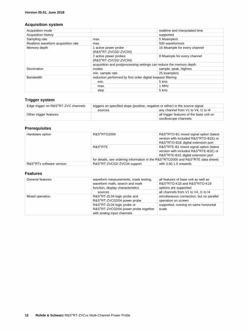
Acquisition system
Acquisition mode realtime and interpolated time
Acquisition history supported
Sampling rate max. 5 Msample/s
Realtime waveform acquisition rate max. 500 waveforms/s
Memory depth 1 active power probe
(R&S®RT-ZVC02/-ZVC04)
16 Msample for every channel
2 active power probes
(R&S®RT-ZVC02/-ZVC04)
8 Msample for every channel
acquisition and postprocessing settings can reduce the memory depth
Decimation modes sample, peak, highres
min. sample rate 25 ksample/s
Bandwidth reduction performed by first order digital lowpass filtering
min. 5 kHz
max. 1 MHz
step 5 kHz
Trigger system
Edge trigger on R&S®RT-ZVC channels triggers on specified slope (positive, negative or either) in the source signal
sources any channel from V1 to V4, I1 to I4
Other trigger features all trigger features of the base unit on
oscilloscope channels
Prerequisites
Hardware option R&S®RTO2000 R&S®RTO-B1 mixed signal option (latest
version with included R&S®RTO-B1E) or
R&S®RTO-B1E digital extension port
R&S®RTE R&S®RTE-B1 mixed signal option (latest
version with included R&S®RTE-B1E) or
R&S®RTE-B1E digital extension port
for details, see ordering information in the R&S®RTO2000 and R&S®RTE data sheets
R&S®RTx software version R&S®RT-ZVC02/-ZVC04 support with 3.60.1.0 onwards
Features
General features waveform measurements, mask testing,
waveform math, search and mark
function, display characteristics
all features of base unit as well as
R&S®RTO-K18 and R&S®RTO-K19
options are supported
sources all channels from V1 to V4, I1 to I4
Mixed operation R&S®RT-ZL04 logic probe and
R&S®RT-ZVC02/04 power probe
simultaneous connection, but no parallel
operation on screen
R&S®RT-ZL04 logic probe or
R&S®RT-ZVC02/04 power probe together
with analog input channels
supported, running on same horizontal
scale
Version 05.01, June 2018
Rohde & Schwarz R&S®RT-ZVCxx Multi-Channel Power Probe 13
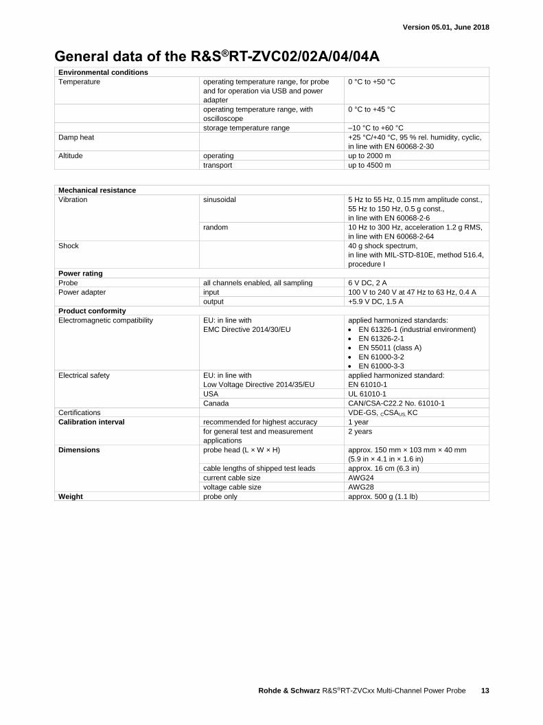
General data of the R&S®RT-ZVC02/02A/04/04A Environmental conditions
Temperature operating temperature range, for probe
and for operation via USB and power
adapter
0 °C to +50 °C
operating temperature range, with
oscilloscope
0 °C to +45 °C
storage temperature range –10 °C to +60 °C
Damp heat +25 °C/+40 °C, 95 % rel. humidity, cyclic,
in line with EN 60068-2-30
Altitude operating up to 2000 m
transport up to 4500 m
Mechanical resistance
Vibration sinusoidal 5 Hz to 55 Hz, 0.15 mm amplitude const.,
55 Hz to 150 Hz, 0.5 g const.,
in line with EN 60068-2-6
random 10 Hz to 300 Hz, acceleration 1.2 g RMS,
in line with EN 60068-2-64
Shock 40 g shock spectrum,
in line with MIL-STD-810E, method 516.4,
procedure I
Power rating
Probe all channels enabled, all sampling 6 V DC, 2 A
Power adapter input 100 V to 240 V at 47 Hz to 63 Hz, 0.4 A
output +5.9 V DC, 1.5 A
Product conformity
Electromagnetic compatibility EU: in line with
EMC Directive 2014/30/EU
applied harmonized standards:
EN 61326-1 (industrial environment)
EN 61326-2-1
EN 55011 (class A)
EN 61000-3-2
EN 61000-3-3
Electrical safety EU: in line with
Low Voltage Directive 2014/35/EU
applied harmonized standard:
EN 61010-1
USA UL 61010-1
Canada CAN/CSA-C22.2 No. 61010-1
Certifications VDE-GS, CCSAUS, KC
Calibration interval recommended for highest accuracy 1 year
for general test and measurement
applications
2 years
Dimensions probe head (L × W × H) approx. 150 mm × 103 mm × 40 mm
(5.9 in × 4.1 in × 1.6 in)
cable lengths of shipped test leads approx. 16 cm (6.3 in)
current cable size AWG24
voltage cable size AWG28
Weight probe only approx. 500 g (1.1 lb)
Version 05.01, June 2018
14 Rohde & Schwarz R&S®RT-ZVCxx Multi-Channel Power Probe
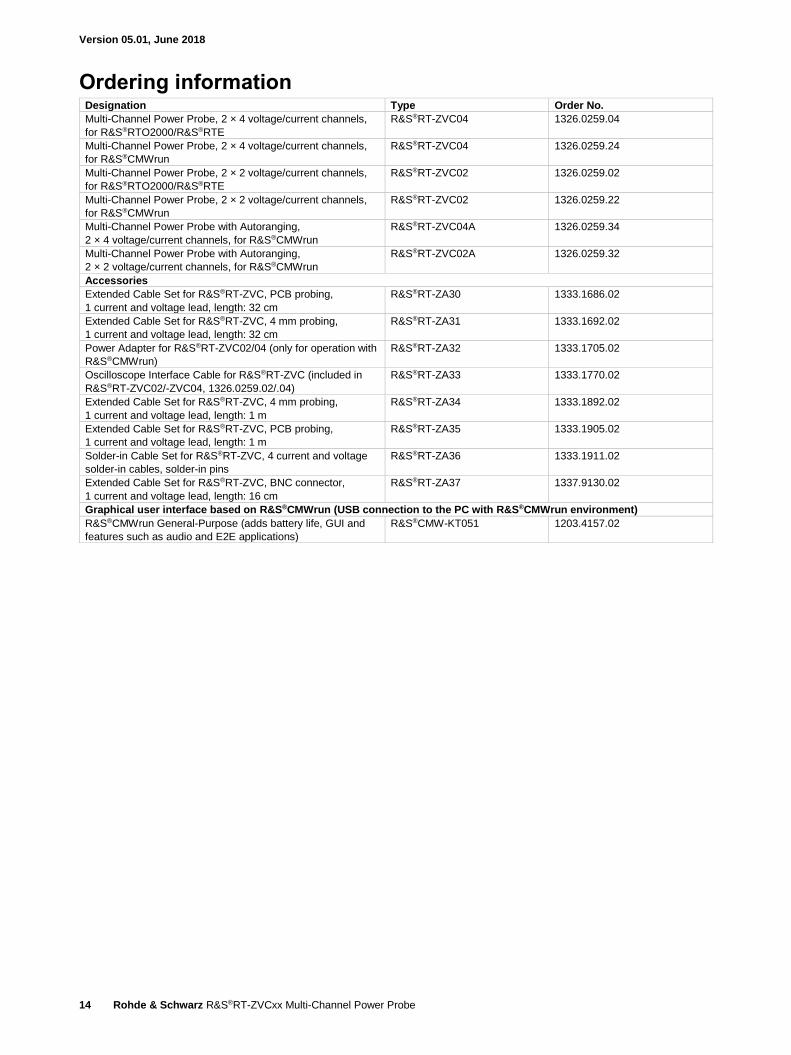
Ordering information Designation Type Order No.
Multi-Channel Power Probe, 2 × 4 voltage/current channels,
for R&S®RTO2000/R&S®RTE
R&S®RT-ZVC04 1326.0259.04
Multi-Channel Power Probe, 2 × 4 voltage/current channels,
for R&S®CMWrun
R&S®RT-ZVC04 1326.0259.24
Multi-Channel Power Probe, 2 × 2 voltage/current channels,
for R&S®RTO2000/R&S®RTE
R&S®RT-ZVC02 1326.0259.02
Multi-Channel Power Probe, 2 × 2 voltage/current channels,
for R&S®CMWrun
R&S®RT-ZVC02 1326.0259.22
Multi-Channel Power Probe with Autoranging,
2 × 4 voltage/current channels, for R&S®CMWrun
R&S®RT-ZVC04A 1326.0259.34
Multi-Channel Power Probe with Autoranging,
2 × 2 voltage/current channels, for R&S®CMWrun
R&S®RT-ZVC02A 1326.0259.32
Accessories
Extended Cable Set for R&S®RT-ZVC, PCB probing,
1 current and voltage lead, length: 32 cm
R&S®RT-ZA30 1333.1686.02
Extended Cable Set for R&S®RT-ZVC, 4 mm probing,
1 current and voltage lead, length: 32 cm
R&S®RT-ZA31 1333.1692.02
Power Adapter for R&S®RT-ZVC02/04 (only for operation with
R&S®CMWrun)
R&S®RT-ZA32 1333.1705.02
Oscilloscope Interface Cable for R&S®RT-ZVC (included in
R&S®RT-ZVC02/-ZVC04, 1326.0259.02/.04)
R&S®RT-ZA33 1333.1770.02
Extended Cable Set for R&S®RT-ZVC, 4 mm probing,
1 current and voltage lead, length: 1 m
R&S®RT-ZA34 1333.1892.02
Extended Cable Set for R&S®RT-ZVC, PCB probing,
1 current and voltage lead, length: 1 m
R&S®RT-ZA35 1333.1905.02
Solder-in Cable Set for R&S®RT-ZVC, 4 current and voltage
solder-in cables, solder-in pins
R&S®RT-ZA36 1333.1911.02
Extended Cable Set for R&S®RT-ZVC, BNC connector,
1 current and voltage lead, length: 16 cm
R&S®RT-ZA37 1337.9130.02
Graphical user interface based on R&S®CMWrun (USB connection to the PC with R&S®CMWrun environment)
R&S®CMWrun General-Purpose (adds battery life, GUI and
features such as audio and E2E applications)
R&S®CMW-KT051 1203.4157.02

Version 05.01, June 2018
Rohde & Schwarz R&S®RT-ZVCxx Multi-Channel Power Probe 15
Service options
Extended Warranty, one year R&S®WE1 Please contact your local
Rohde & Schwarz sales
office.
Extended Warranty, two years R&S®WE2
Extended Warranty, three years R&S®WE3
Extended Warranty, four years R&S®WE4
Extended Warranty with Calibration Coverage, one year R&S®CW1
Extended Warranty with Calibration Coverage, two years R&S®CW2
Extended Warranty with Calibration Coverage, three years R&S®CW3
Extended Warranty with Calibration Coverage, four years R&S®CW4
Extended Warranty with Accredited Calibration Coverage, one year R&S®AW1
Extended Warranty with Accredited Calibration Coverage, two years R&S®AW2
Extended Warranty with Accredited Calibration Coverage, three years R&S®AW3
Extended Warranty with Accredited Calibration Coverage, four years R&S®AW4
Extended warranty with a term of one to four years (WE1 to WE4)
Repairs carried out during the contract term are free of charge 1. Necessary calibration and adjustments carried out during repairs are
also covered.
Extended warranty with calibration (CW1 to CW4)
Enhance your extended warranty by adding calibration coverage at a package price. This package ensures that your
Rohde & Schwarz product is regularly calibrated, inspected and maintained during the term of the contract. It includes all repairs 1 and
calibration at the recommended intervals as well as any calibration carried out during repairs or option upgrades.
Extended warranty with accredited calibration (AW1 to AW4)
Enhance your extended warranty by adding accredited calibration coverage at a package price. This package ensures that your
Rohde & Schwarz product is regularly calibrated under accreditation, inspected and maintained during the term of the contract. It
includes all repairs 1 and accredited calibration at the recommended intervals as well as any accredited calibration carried out during
repairs or option upgrades.
1 Excluding defects caused by incorrect operation or handling and force majeure. Wear-and-tear parts are not included.

R&S® is a registered trademark of Rohde & Schwarz GmbH & Co. KG
Trade names are trademarks of the owners
PD 5214.7058.22 | Version 05.01 | June 2018 (sk)
R&S®RT-ZVCxx Multi-Channel Power Probe
Data without tolerance limits is not binding | Subject to change
© 2016 - 2018 Rohde & Schwarz GmbH & Co. KG | 81671 Munich, Germany
Service that adds value Worldwide Local and personalized Customized and flexible Uncompromising quality Long-term dependability
5214
.70
58.2
2 0
5.01
PD
P 1
en
Sustainable product design Environmental compatibility and eco-footprint Energy efficiency and low emissions Longevity and optimized total cost of ownership
Certified Environmental Management
ISO 14001Certified Quality Management
ISO 9001
Regional contact Europe, Africa, Middle East | +49 89 4129 12345 [email protected]
North America | 1 888 TEST RSA (1 888 837 87 72) [email protected]
Latin America | +1 410 910 79 88 [email protected]
Asia Pacific | +65 65 13 04 88 [email protected]
China | +86 800 810 82 28 | +86 400 650 58 96 [email protected]
Rohde & SchwarzThe Rohde & Schwarz electronics group offers innovative solutions in the following business fields: test and mea-surement, broadcast and media, secure communications, cybersecurity, monitoring and network testing. Founded more than 80 years ago, the independent company which is headquartered in Munich, Germany, has an extensive sales and service network with locations in more than 70 countries.
www.rohde-schwarz.com
5214705822
RT-ZVCxx_dat-sw_en_5214-7058-22_v0501_Cover.indd 2 06.06.2018 08:05:50