Embed Size (px)
DESCRIPTION
RT-TRACS A daptive Control Algorithms VFC-OPAC Farhad Pooran PB Farradyne Inc. TRB A3A18 Mid-Year Meeting and Adaptive Control Workshop July 12-14, 1998 Pacific Grove, CA. VFC-OPAC (Virtual Fixed Cycle OPAC). Real-time, traffic adaptive control of signals in a network - PowerPoint PPT Presentation
Citation preview
RT-TRACS Adaptive Control Algorithms
VFC-OPAC
Farhad Pooran
PB Farradyne Inc.
TRB A3A18 Mid-Year Meeting andAdaptive Control Workshop
July 12-14, 1998Pacific Grove, CA
VFC-OPAC (Virtual Fixed Cycle OPAC)
• Real-time, traffic adaptive control of signals in a network
• Distributed optimization based on the OPAC (Optimization Policies for Adaptive Control) smart controller
• Multi-layer network control architecture• Variable cycle in time and in Space
VFC-OPAC Development History
• OPAC I: Dynamic Programming optimization– infinite horizon (single intersection)
• OPAC II: optimal sequential constrained search procedure– finite projection horizon length
• OPAC III: rolling horizon approach– real-time implementation
• OPAC IV (VFC-OPAC): network model for real-time– traffic-adaptive control
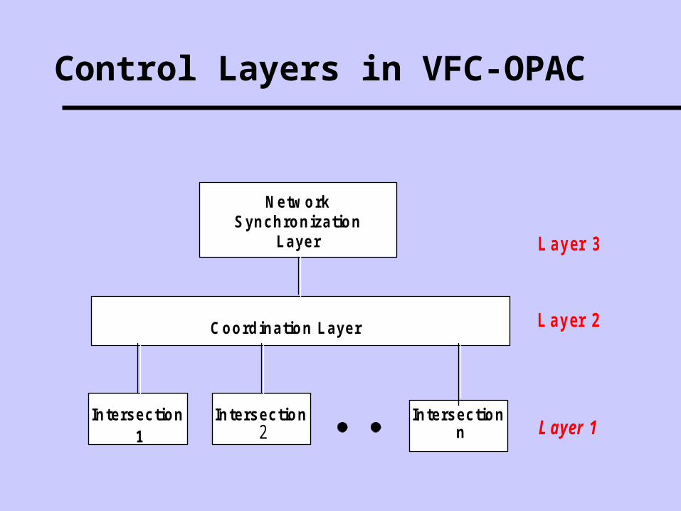
Control Layers in VFC-OPAC
Netw orkSynchronization
Layer
Coordination Layer
Intersectionn
L a y er 3
L a y er 2
L ayer 1Intersection
2Intersection
1
Control Layers in VFC-OPAC
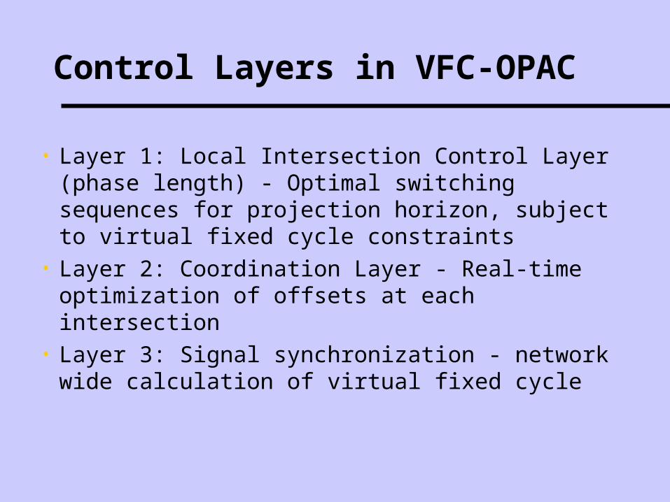
• Layer 1: Local Intersection Control Layer (phase length) - Optimal switching sequences for projection horizon, subject to virtual fixed cycle constraints
• Layer 2: Coordination Layer - Real-time optimization of offsets at each intersection
• Layer 3: Signal synchronization - network wide calculation of virtual fixed cycle
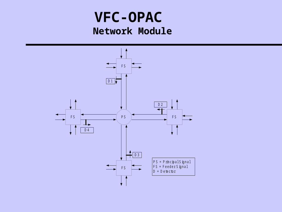
VFC-OPAC Network Module
P SFS FS
FS
FS
D 4
D 2
D 1
D 3
P S = P rincipa l S igna lFS = Feeder S igna lD = D etector
Data Requirements
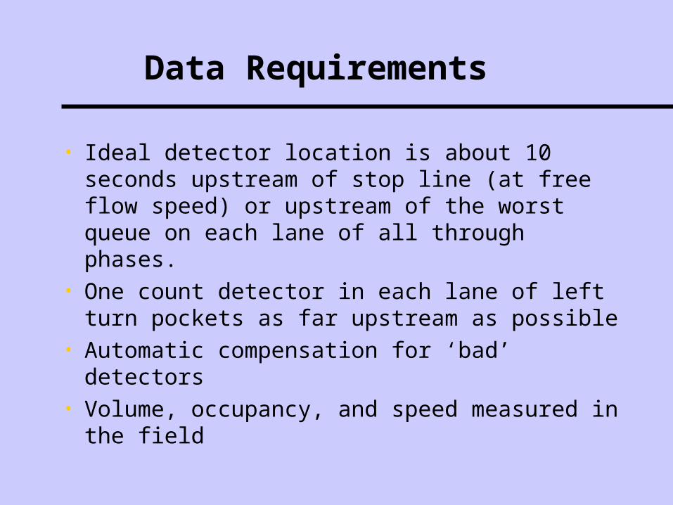
• Ideal detector location is about 10 seconds upstream of stop line (at free flow speed) or upstream of the worst queue on each lane of all through phases.
• One count detector in each lane of left turn pockets as far upstream as possible
• Automatic compensation for ‘bad’ detectors• Volume, occupancy, and speed measured in the
field
Control Variables
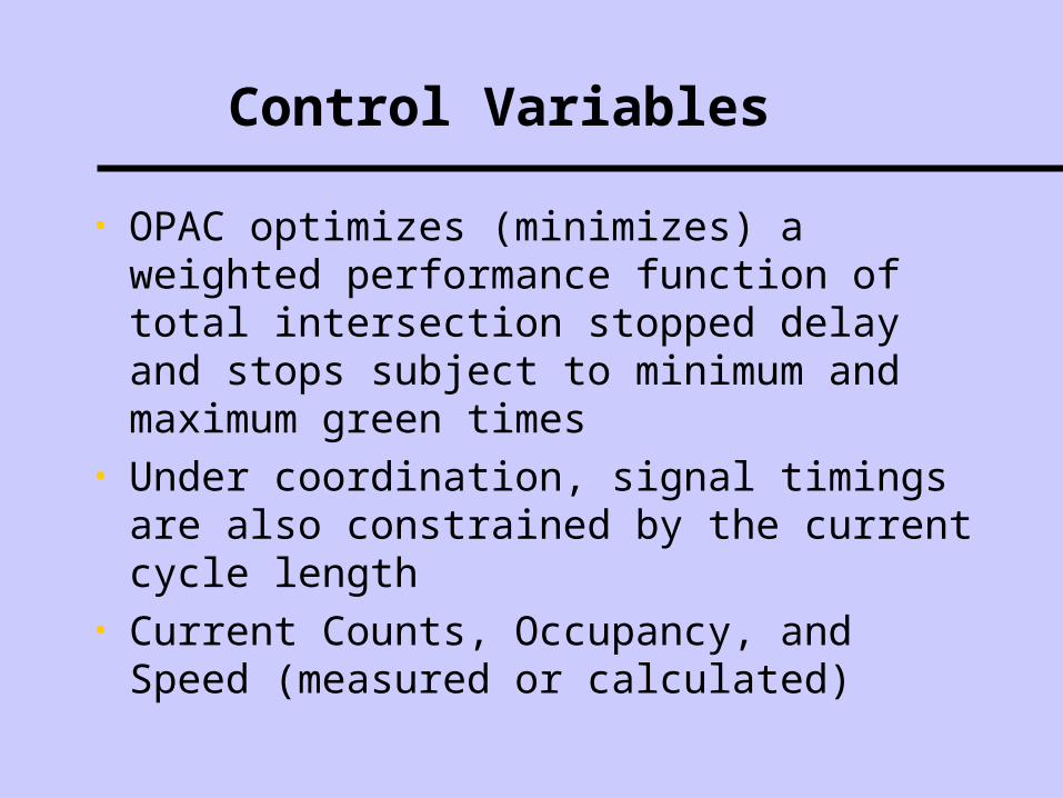
• OPAC optimizes (minimizes) a weighted performance function of total intersection stopped delay and stops subject to minimum and maximum green times
• Under coordination, signal timings are also constrained by the current cycle length
• Current Counts, Occupancy, and Speed (measured or calculated)
Decision Variables
• Terminate the current phase in ring 1 (Yes or No)
• Terminate the current phase in ring 2 (Yes or No)
State Variables
• Signal status
• Elapsed time since last signal status change
• Standing queues
• Cumulative delay
• Cumulative stops
Constraints on Decision Variables
• Phase interval timings (minimum green, maximum green, yellow, all red, walk and don’t walk)
• Opposing demand (vehicle and pedestrian calls)
• Cycle length constraints
• Offset adjustments
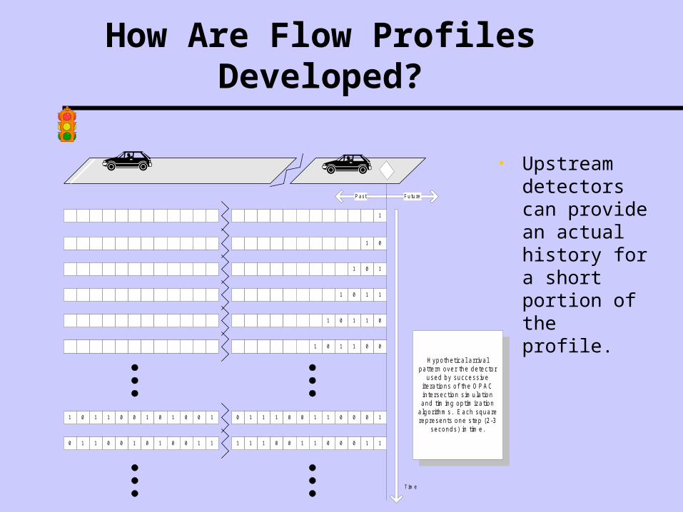
How Are Flow Profiles Developed?
• Upstream detectors can provide an actual history for a short portion of the profile.
• Smoothed volume can be used for uniform profiles.
• Platoon identification and smoothing can be used for cyclic profiles.
• Adjustments can be made to eliminate double counting (left turn phases).
How Are Flow Profiles Developed?
• Upstream detectors can provide an actual history for a short portion of the profile.
Past Future
1
1 0
1 0 1
1 0 1 1
1 0 1 1 0
1 0 1 1 0 0
H ypo the tica l a rriva lpa tte rn ove r the de tec to r
used by success iveite ra tions o f the O P A Cin te rsec tion s im u la tionand tim ing op tim iza tion
a lgo rithm s. E ach squarerep resen ts one s tep (2 -3
seconds) in tim e .
1 0 1 1 0 0 1 0 1 0 0 1 0 1 1 1 0 0 1 1 0 0 0 1
0 1 1 0 0 1 0 1 0 0 1 1 1 1 1 0 0 1 1 0 0 0 1 1
T im e
Cycle Length Optimization
• Meet phase switching timing determined by local conditions, while maintaining a capability for coordination with adjacent intersections
• Using a cycle length constraint, the cycle length can start or terminate only within a prescribed range
• All VFC-OPAC controlled intersections can oscillate with a common frequency
Offset Optimization
Options:• Leave current offset ( zero change)• Move right one interval (+2 sec)• Move left one interval (-2 sec)
Data Sampling
• Develops a flow profile for each phase using a user-specified time interval
• Head of the profile is actual counts from the recent past.
• The tail of the profile is projected for the future using smoothed volume
• Smoothed data: volume, occupancy, speed, platoon headways, flow profiles, and phase duration
MOE’s
• Volume, occupancy, speed by detector and phase.
• Estimated measure of queue, delay, and stops by phase.
Phasing Flexibility
• Supports 8 phases in a dual ring configuration• Does not explicitly control phase sequence• Can recognize and adapt to changes in
sequence immediately
System Architecture
• Isolated intersection control - fully distributed• Coordinated system control - basically distributed
except for the following tasks:– cycle length determination is made at central and
communicated periodically to the intersection controller– peer-to-peer information is communicated through central
on a periodic basis (if adjacent intersection controllers are not linked physically)
Hardware Requirements
• Local Controller:– a computer board with a floating point processor
and 4 MB memory (e.g., 68040 or 68060 boards)
• Central:– 3 to 4 PC’s for OI, Server, dB, Device Drivers and
Communications with at least 2 GB of HD and 64 MB RAM
Communication Requirements
• Communications with Central: OPAC status is polled
• Communications with Signal Control Software
• Peer-to-peer communications
Network Type
• For coordinated signal control, cycle lengths are calculated for user-specified groups (sections) of signals (arterials or networks)
• The cycle is calculated using the critical v/c ratios of the critical intersection in the section
• The field computer optimizes offsets with its neighbors, not the entire section.
Special Features
• Preemption: – Preemption will always take priority over OPAC. – Prioritizes transit and emergency vehicles if they are
restricted to particular lanes – Recovers from a preemption immediately
Special Features
• Oversaturated Conditions:– Isolated intersection control - OPAC will provide
maximum green to the affected phase(s) if occupancy on the OPAC detectors exceeds a user-specified threshold.
– Coordinated control� Provide maximum green to congested phases, subject to the
current cycle length� Adjust cycle lengths in response to increasing congestion
Field Installations
• 1986 - Isolated OPAC in Arlington, Virginia and Tucson, Arizona (Single intersection control)
• 1996 - Isolated OPAC at a Route 18 site in New Jersey (15-intersection arterial)
• 1998 - Coordinated OPAC at Reston Pkwy site, in Reston, Virginia (16-intersection arterial )