Embed Size (px)
Citation preview
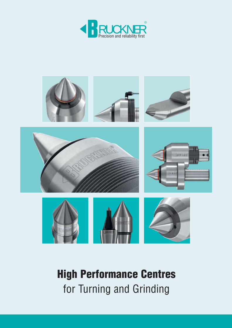
High Performance Centresfor Turning and Grinding
RUCKNERPrecision and reliability first
®

2
Page 4/5
History
RUCKNERPräzision aus gutem Hause.
®
Page 6/7
Quick Find
High performancelive centres
Page 8/9
S SeriesStandard centres
(without spring loading) for high precision turning,CNC turning and cylindrical
grinding
Technical information
Page 18
NC SeriesLive centres without spring
loading, for turning, high speed CNC turning.Incorporating TOP-SEAL
sealing system
Technical information
Page 10
Types S/SG60°
Page 11
Types SKOP/SKOPG60°/40°
Page 19
Type NC60°/40°
Page 20/21
Type NCEfor interchangeable inserts
Page 22
LK SeriesLive centres without springloading for high performanceturning, hard turning andcylindrical grinding.
High stiffness due to shortdesign and optimised bearing
arrangement
Technical information
Page 28/29
LR/LD SeriesSpring loaded centres.
LR: with pressure indicationfor turning, CNC turning, formulti-spindle machines, face driver applications
LD: without pressure indicationfor turning, CNC turning, withexpansion compensation
Technical information
Page 30
Type LRS60°
Page 31
Type LRV60°/40°
Page 34
Type LDS60°
Page 32/33
Type LREfor interchangeable inserts
Page 44 Page 45
Types MR/MRG60°, 75°, 90°
with tailstock sleeve support
Page 46/47
Type MZR60°, 75°, 90°
with tailstock sleeve support
Page 46/47
Types MZ/AMZ60°, 75°, 90°
Page 54/55
Carbidedead centresPoint angle 60°,
out-of-roundness ≤ 0.8µm
Technical information
Page 56 Page 57
Form Z
Form R
Page 58
Forms HE, HL
Form HS
Form HV
Page 57
Form B
Form HB
Forms E, L
Form V
Page 62
Tool steeldead centres
with and without draw-offthread, point angle 60°
Technical information
Page 64
Form 250Morse taper
metr. taper 1:20, taper 1:10
Page 66
Adapter sleevesfor interchangeable inserts
Reduction sleeves
Page 65
Forms 220/230Steep taper 30/40
Forms 255/256/257/258
Morse taper metr. taper 1:20, taper 1:10
Index RUCKNER®
Page 23
Type LKS60°
Page 63
Types M/MGTypes AM/AMG
60°, 75°, 90°
All dimensions in mmKatalog SPE11
M/MZ Seriesfor heavy-duty machining forturning and cylindrical grinding
M SeriesCentrepoint without spring
loadingMZ Series
Centrepoint with spring loadingand pressure indicationTechnical information
Page 42/43
3
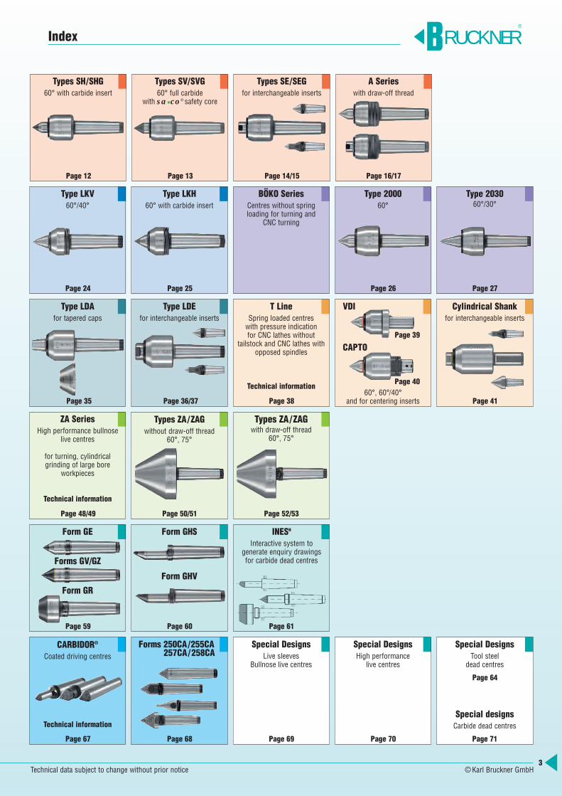
Page 12
Types SH/SHG60° with carbide insert
Page 13
Types SV/SVG60° full carbide
with sa •co® safety core
Page 14/15
Types SE/SEGfor interchangeable inserts
Page 16/17
A Serieswith draw-off thread
BÖKO SeriesCentres without spring loading for turning and
CNC turning
Page 38
T LineSpring loaded centres with pressure indication for CNC lathes without
tailstock and CNC lathes withopposed spindles
Technical information
Page 48/49
ZA SeriesHigh performance bullnose
live centres
for turning, cylindrical grinding of large bore
workpieces
Technical information
Page 60
Form GHS
Form GHV
Page 59
Form GE
Forms GV/GZ
Form GR
Page 67
CARBIDOR®
Coated driving centres
Technical information
Page 68 Page 69
Special DesignsLive sleeves
Bullnose live centres
Page 71
Special DesignsTool steel
dead centres
Special designsCarbide dead centres
Page 70
Special DesignsHigh performance
live centres
Forms 250CA/255CA257CA/258CA
Index RUCKNER®
Type LKV60°/40°
Page 24
Type LKH60° with carbide insert
Page 25
Type 200060°
Page 26
Type 203060°/30°
Page 27
Type LDAfor tapered caps
Page 35
Type LDEfor interchangeable inserts
Page 36/37
Page 39
VDI
CAPTO
Page 40
Page 41
Types ZA/ZAGwithout draw-off thread
60°, 75°
Page 50/51
Types ZA/ZAGwith draw-off thread
60°, 75°
Page 52/53
60°, 60°/40°and for centering inserts
Cylindrical Shankfor interchangeable inserts
Technical data subject to change without prior notice ©Karl Bruckner GmbH
INESH
Interactive system to generate enquiry drawings for carbide dead centres
Page 61
Page 64
4
The Past>
In 1918 Karl Bruckner founded his engineering workshop in Stuttgart andlaid the cornerstone for a success storywhich continues today – more than 90years on. Initially the business focusedon the repair and overhaul of machinesbut his ability to find innovative solutionsto technical problems led him to rapidlyobtain orders for his own designs ofpedestal grinders and small lathes.
He commenced manufacture of lathe centres and in 1920 as a pioneer in thisfield he developed and produced his firstrotating tailstock centre.
On the early death of Karl Bruckner in1931 his son Karl Georg Bruckner tookover management of the company. By the
end of 1944 bombs had destroyed thefactory, which he rebuilt under the very difficult conditions of 1945. In the following years Karl Georg focused onmanufacturing and developing both liveand dead centres. Diligently and ambitiously he expanded the companyand its distribution network.
The company’s relocation to its presentpremises in Weinstadt-Grossheppachabout 25 kilometers away was an important step for the company’s futuregrowth. In 1979 Karl Georg handed overmanagement of the company to hisdaughter Hilde and his son Karl-Friedrich.In 1984 the youngest son Manfred joinedthe company and its management.
RUCKNER®
The founder, Karl Bruckner
Karl-Georg Bruckner
Rotating high performance centrefor heavy-duty machining, with 2 roller bearings (1936)
Brochure 1940
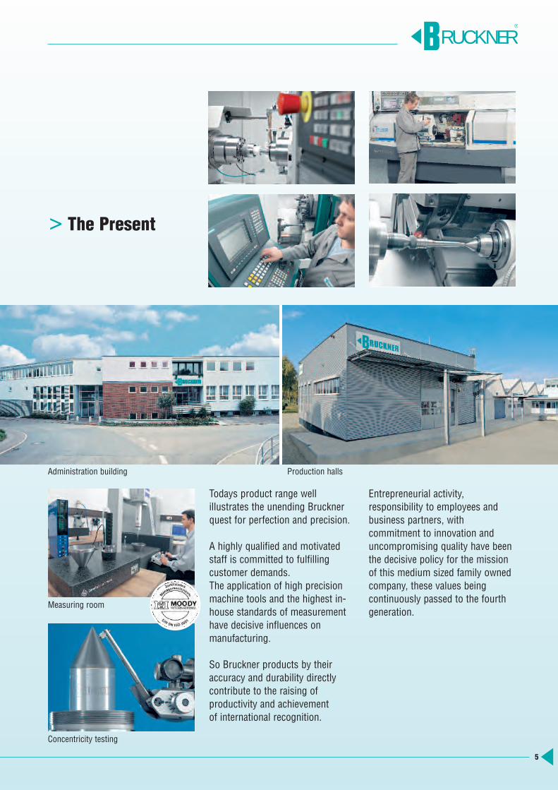
Lathe with rotating high performance centre from BRUCKNER
Company premises in Stuttgart 1920 New building 1963 in Weinstadt-Grossheppach
5
The Present>
Todays product range well illustrates the unending Brucknerquest for perfection and precision.
A highly qualified and motivatedstaff is committed to fulfillingcustomer demands.The application of high precisionmachine tools and the highest in-house standards of measurementhave decisive influences on manufacturing.
So Bruckner products by theiraccuracy and durability directlycontribute to the raising of productivity and achievement of international recognition.
Entrepreneurial activity, responsibility to employees andbusiness partners, with commitment to innovation anduncompromising quality have beenthe decisive policy for the missionof this medium sized family ownedcompany, these values being continuously passed to the fourthgeneration.
RUCKNER®
Measuring room
Concentricity testing
Administration building Production halls
6
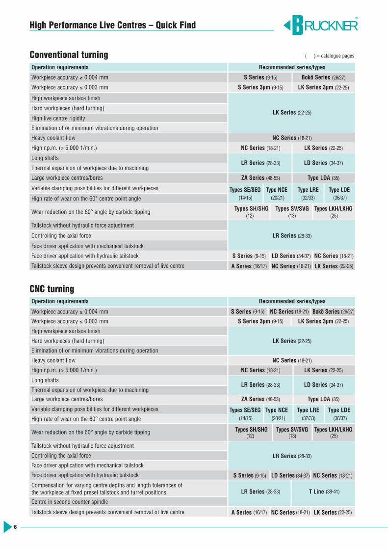
High Performance Live Centres – Quick Find
Conventional turning
CNC turning
Operation requirements Recommended series/types
Workpiece accuracy ≥ 0.004 mm S Series (9-15) Bokö Series (26/27)
Workpiece accuracy ≤ 0.003 mm S Series 3µm (9-15) LK Series 3µm (22-25)
High workpiece surface finish
Hard workpieces (hard turning)LK Series (22-25)
High live centre rigidity
Elimination of or minimum vibrations during operation
Heavy coolant flow NC Series (18-21)
High r.p.m. (> 5.000 1/min.) NC Series (18-21) LK Series (22-25)
Long shaftsLR Series (28-33) LD Series (34-37)
Thermal expansion of workpiece due to machining
Large workpiece centres/bores ZA Series (48-53) Type LDA (35)
Variable clamping possibilities for different workpieces Types SE/SEG Type NCE Type LRE Type LDEHigh rate of wear on the 60° centre point angle
Wear reduction on the 60° angle by carbide tipping Types SH/SHG Types SV/SVG Types LKH/LKHG
Tailstock without hydraulic force adjustment
Controlling the axial force LR Series (28-33)
Face driver application with mechanical tailstock
Face driver application with hydraulic tailstock S Series (9-15) LD Series (34-37) NC Series (18-21)
Tailstock sleeve design prevents convenient removal of live centre A Series (16/17) NC Series (18-21) LK Series (22-25)
Operation requirements Recommended series/types
Workpiece accuracy ≥ 0.004 mm S Series (9-15) NC Series (18-21) Bokö Series (26/27)
Workpiece accuracy ≤ 0.003 mm S Series 3µm (9-15) LK Series 3µm (22-25)
High workpiece surface finish
Hard workpieces (hard turning) LK Series (22-25)
Elimination of or minimum vibrations during operation
Heavy coolant flow NC Series (18-21)
High r.p.m. (> 5.000 1/min.) NC Series (18-21) LK Series (22-25)
Long shaftsLR Series (28-33) LD Series (34-37)
Thermal expansion of workpiece due to machining
Large workpiece centres/bores ZA Series (48-53) Type LDA (35)
Variable clamping possibilities for different workpieces Types SE/SEG Type NCE Type LRE Type LDE
High rate of wear on the 60° centre point angle
Wear reduction on the 60° angle by carbide tipping Types SH/SHG Types SV/SVG Types LKH/LKHG
Tailstock without hydraulic force adjustment
Controlling the axial force LR Series (28-33)
Face driver application with mechanical tailstock
Face driver application with hydraulic tailstock S Series (9-15) LD Series (34-37) NC Series (18-21)
Compensation for varying centre depths and length tolerances of LR Reihe T Liniethe workpiece at fixed preset tailstock and turret positions
Centre in second counter spindle
Tailstock sleeve design prevents convenient removal of live centre A Series (16/17) NC Series (18-21) LK Series (22-25)
RUCKNER®
(14/15)
(12) (13) (25)
(20/21) (32/33) (36/37)
(14/15)
(12) (13) (25)
(20/21) (32/33) (36/37)
LR Series (28-33) T Line (38-41)
( ) = catalogue pages
7
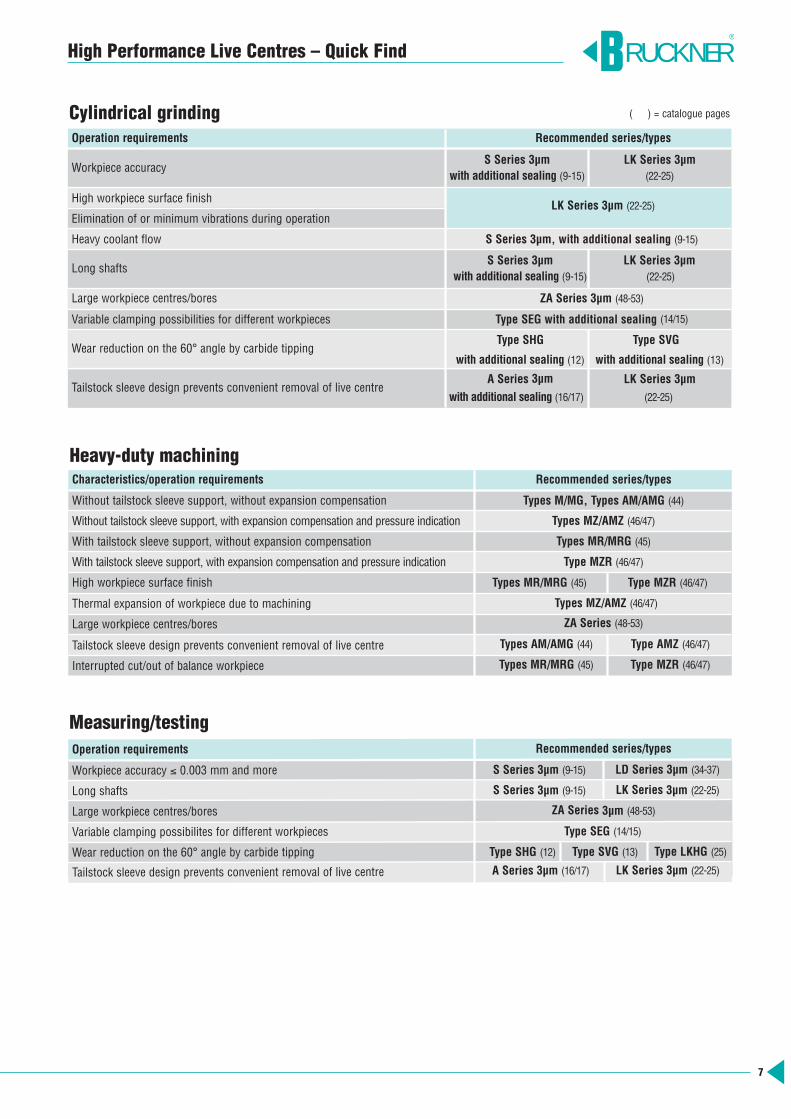
High Performance Live Centres – Quick Find
Characteristics/operation requirements Recommended series/types
Without tailstock sleeve support, without expansion compensation Types M/MG, Types AM/AMG (44)
Without tailstock sleeve support, with expansion compensation and pressure indication Types MZ/AMZ (46/47)
With tailstock sleeve support, without expansion compensation Types MR/MRG (45)
With tailstock sleeve support, with expansion compensation and pressure indication Type MZR (46/47)
High workpiece surface finish Types MR/MRG (45) Type MZR (46/47)
Thermal expansion of workpiece due to machining Types MZ/AMZ (46/47)
Large workpiece centres/bores ZA Series (48-53)
Tailstock sleeve design prevents convenient removal of live centre Types AM/AMG (44) Type AMZ (46/47)
Interrupted cut/out of balance workpiece Types MR/MRG (45) Type MZR (46/47)
Heavy-duty machining
Operation requirements Recommended series/types
Workpiece accuracy ≤ 0.003 mm and more S Series 3µm (9-15) LD Series 3µm (34-37)
Long shafts S Series 3µm (9-15) LK Series 3µm (22-25)
Large workpiece centres/bores ZA Series 3µm (48-53)
Variable clamping possibilites for different workpieces Type SEG (14/15)
Wear reduction on the 60° angle by carbide tipping Type SHG (12) Type SVG (13) Type LKHG (25)
Tailstock sleeve design prevents convenient removal of live centre A Series 3µm (16/17) LK Series 3µm (22-25)
Measuring/testing
Cylindrical grindingOperation requirements Recommended series/types
Workpiece accuracy S Series 3µm LK Series 3µm
with additional sealing (9-15) (22-25)
High workpiece surface finishLK Series 3µm (22-25)
Elimination of or minimum vibrations during operation
Heavy coolant flow S Series 3µm, with additional sealing (9-15)
Long shaftsS Series 3µm LK Series 3µm
with additional sealing (9-15) (22-25)
Large workpiece centres/bores ZA Series 3µm (48-53)
Variable clamping possibilities for different workpieces Type SEG with additional sealing (14/15)
Wear reduction on the 60° angle by carbide tippingType SHG Type SVG
with additional sealing (12) with additional sealing (13)
Tailstock sleeve design prevents convenient removal of live centreA Series 3µm LK Series 3µm
with additional sealing (16/17) (22-25)
RUCKNER®
( ) = catalogue pages

TypeS TypeSG Morse taper Runout max. FaxType S Type SG daN
5001 5121 1 0.005 0.003 805001-2 5121-2 2 0.005 0.003 805001-3 5121-3 3 0.005 0.003 805002 5122 2 0.005 0.003 1605003 5123 3 0.005 0.003 1605006 5126 3 0.005 0.003 2105004 5124 4 0.005 0.003 2105007 5127 4 0.005 0.003 4505005 5125 5 0.005 0.003 6005008 5128 5 0.005 0.003 6005009 5129 6 0.005 0.003 600
8
RUCKNER®
High Performance Live Centres BRUCKNER WORKS STANDARD
Test report for concentricity accuracy Every single BRUCKNER high performance live centre is tested for itsrunout under axial load. The test result is stamped into the high performance centre and is guaranteed by the testreport.
BRUCKNER WORKS STANDARDOur high performance live centres – standard as well as special designs – are produced and tested according to our works standard. Materials, production and testing are subject to strict quality guidelines guaranteeing function and performance of our tools.
Tolerance of taper shankThe Morse taper is ground according to DIN 228 AT4 (gauge accuracy). This fine tolerance guarantees a close fit of the high performance centre in the tailstock and therefore the full utilisation of the concentricity accuracy.
Precision bearingsThe bearing seats in the housing and onthe centrepoint are precision-ground. The bearings and their seats are selectedto fit.Result: high stability, concentricity andlong life.
Load valuesThe load values given in our tables arecalculated with the world wide acknowledged software KISSsoft. Whenused in keeping with currently valid standards DIN and ISO, this softwareguarantees a safe and reliable load calculation.
CentrepointThe centrepoint is of through-hardenedalloy tool steel resistant to wear.
HousingThe housing is of alloy tool steel withhigh tensile strength. Housing head andshank are case-hardened for protectionfrom damage.
MaintenanceThe bearings are maintenance-free due to permanent lubrication.
Repair serviceOur repair service is at your disposal forany repairs. We judge the tool’s conditionand inform you about the extent ofnecessary repairs.
Example: table „maximum runout“ for types S, SG
www.KISSsoft.AG
9
RUCKNER®
High Performance Live Centres S Series
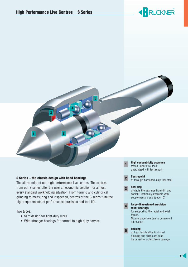
S Series – the classic design with head bearingsThe all-rounder of our high performance live centres. The centres from our S series offer the user an economic solution for almost every standard workholding situation. From turning and cylindrical grinding to measuring and inspection, centres of the S series fulfil thehigh requirements of performance, precision and tool life.
Two types: Slim design for light-duty work With stronger bearings for normal to high-duty service
High concentricity accuracytested under axial loadguaranteed with test report
Centrepointof through-hardened alloy tool steel
Seal ringprotects the bearings from dirt and coolant. Optionally available with supplementary seal (page 10)
Large-dimensioned precisionroller bearingsfor supporting the radial and axialforces. Maintenance-free due to permanent lubrication
Housingof high tensile alloy tool steel housing and shank are case-hardened to protect from damage
1
2
3
4
5
1 2
34
5
10
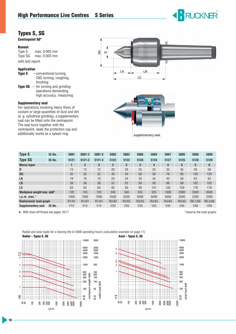
Type S ID.No. 5001 5001-2 5001-3 5002 5003 5006 5004 5007 5005 5008 5009
Type SG ID.No. 5121 5121-2 5121-3 5122 5123 5126 5124 5127 5125 5128 5129
Morse taper 1 2 3 2 3 3 4 4 5 5 6D 13 13 13 20 20 25 25 35 45 58 58DG 32 32 32 45 45 58 58 76 95 120 120LA 19 19 19 24 24 34 34 43 59 63 63LB 38 38 38 52 52 58 58 68 89 102 102LC 63 63 64 82 83 99 101 120 159 178 178Workpiece weight max. daN* 120 120 120 340 340 525 525 1000 2000 2500 3000r.p.m. max.* 7000 7000 7000 5500 5500 5000 5000 4000 3500 2300 2300Radial/axial load graph R1/A1 R1/A1 R1/A1 R2/A2 R2/A2 R3/A3 R3/A3 R4/A4 R5/A5 R6.1/A6 R6.2/A6Supplementary seal ID.No. V13 V13 V13 V20 V20 V25 V25 V35 V45 V58 V58
With draw-off thread see pages 16/17 *observe the load graphs▼5040 10
0
200
300
5000400
500
1000
2000
3000
4000
1000
0
Drehzahl 1/min
10000
500040003000
2000
1000
500400300
200
100
5040
200
2025
100
50
150
250
500
1000
20001500
2500
5000
Rad
ialb
elas
tung
daN
Wer
kstü
ckge
wic
ht d
aN
3
6.1
2
1
4
R
6.2
5
30040 50 100
200
500
400
1000
2000
4000
3000
5000
1000
0
1000
4050
100
200
300400500
3000
2000
50004000
10000
Axi
albe
last
ung
daN
Drehzahl 1/min
A
4
2
1
5
3
6
Radial and axial loads for a bearing life of 2000 operating hours (calculation example on page 11)Radial – Types S, SG Axial – Types S, SG
RUCKNER®
LA
LC
LB
DG D
Types S, SGCentrepoint 60°
RunoutType S max. 0.005 mmType SG max. 0.003 mmwith test report
ApplicationType S –conventional turning,
CNC turning, roughing, finishing
Type SG – for turning and grinding operations demanding high accuracy, measuring
Supplementary sealFor operations involving heavy flows ofcoolant or large quantities of dust and dirt(e. g. cylindrical grinding), a supplementaryseal can be fitted onto the centrepoint. The seal turns together with the centrepoint, seals the protection cap andadditionally works as a splash ring.
High Performance Live Centres S Series
supplementary seal
r.p.m. r.p.m.
workpiece weight daN
radial load daN
axial load daN
11
High Performance Live Centres S Series
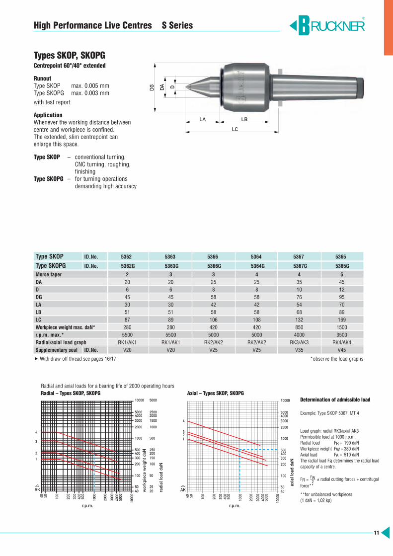
Types SKOP, SKOPGCentrepoint 60°/40° extended
RunoutType SKOP max. 0.005 mmType SKOPG max. 0.003 mmwith test report
ApplicationWhenever the working distance betweencentre and workpiece is confined. The extended, slim centrepoint can enlarge this space.
Type SKOP – conventional turning, CNC turning, roughing, finishing
Type SKOPG – for turning operations demanding high accuracy
Type SKOP ID.No. 5362 5363 5366 5364 5367 5365
Type SKOPG ID.No. 5362G 5363G 5366G 5364G 5367G 5365G
Morse taper 2 3 3 4 4 5DA 20 20 25 25 35 45D 6 6 8 8 10 12DG 45 45 58 58 76 95LA 30 30 42 42 54 70LB 51 51 58 58 68 89LC 87 89 106 108 132 169Workpiece weight max. daN* 280 280 420 420 850 1500r.p.m. max.* 5500 5500 5000 5000 4000 3500Radial/axial load graph RK1/AK1 RK1/AK1 RK2/AK2 RK2/AK2 RK3/AK3 RK4/AK4Supplementary seal ID.No. V20 V20 V25 V25 V35 V45
With draw-off thread see pages 16/17 *observe the load graphs
Radial and axial loads for a bearing life of 2000 operating hours Radial – Types SKOP, SKOPG Axial – Types SKOP, SKOPG
Determination of admissible load
Example: Type SKOP 5367, MT 4
Load graph: radial RK3/axial AK3Permissible load at 1000 r.p.m.Radial load FR = 190 daNWorkpiece weight FW =380 daNAxial load FA = 510 daNThe radial load FR determines the radial load capacity of a centre.
FR = ± radial cutting forces + centrifugalforce**
**for unbalanced workpieces(1 daN = 1,02 kp)
FW2
RUCKNER®
5040 100
200
300
5000400
500
1000
2000
3000
4000
1000
0
Drehzahl 1/min
10000
500040003000
2000
1000
500400300
200
100
5040
200
2025
100
50
150
250
500
1000
20001500
2500
5000
Rad
ialb
elas
tung
daN
Wer
kstü
ckge
wic
ht d
aN
2
1
3
RK
4
30040 50 100
200
500
400
1000
2000
4000
3000
5000
1000
0
1000
4050
100
200
300400500
3000
2000
50004000
10000
Axi
albe
last
ung
daN
Drehzahl 1/min
AK
4
21
3
DG DA
LA LB
LC
D
r.p.m. r.p.m.
workpiece weight daN
radial load daN
axial load daN
12
High Performance Live Centres S Series
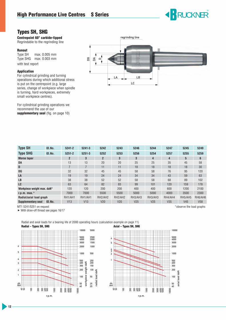
Types SH, SHGCentrepoint 60° carbide-tippedRegrindable to the regrinding line
RunoutType SH max. 0.005 mmType SHG max. 0.003 mmwith test report
ApplicationFor cylindrical grinding and turning operations during which additional stressis put on the centrepoint (e.g. large series, change of workpiece when spindleis turning, hard workpieces, extremelysmall workpiece centres).
For cylindrical grinding operations we recommend the use of our supplementary seal (fig. on page 10)
Type SH ID.No. 5241-2 5241-3 5242 5243 5246 5244 5247 5245 5249
Type SHG ID.No. 5251-2 5251-3 5252 5253 5256 5254 5257 5255 5259
Morse taper 2 3 2 3 3 4 4 5 6DA 13 13 20 20 25 25 35 45 58D 7 7 11 11 18 18 18 18 30DG 32 32 45 45 58 58 76 95 120LA 19 19 24 24 34 34 43 59 63LB 38 38 52 52 58 58 68 89 102LC 63 64 82 83 99 101 120 159 178Workpiece weight max. daN* 120 120 200 200 400 400 600 1200 2100r.p.m. max.* 7000 7000 5500 5500 5000 5000 4000 3500 2300Radial/axial load graph RH1/AH1 RH1/AH1 RH2/AH2 RH2/AH2 RH3/AH3 RH3/AH3 RH4/AH4 RH5/AH5 RH6/AH6Supplementary seal ID.No. V13 V13 V20 V20 V25 V25 V35 V45 V58
MT1 5241/5251 on request *observe the load graphs With draw-off thread see pages 16/17
RUCKNER®
50
40
100
200
300
5000
400
500
1000
2000
3000
40
00
1000
0
10000
5000 4000 3000
2000
1000
500 400 300
200
100
50 40
200
20 25
100
50
150
250
500
1000
2000 1500
2500
5000
Rad
ialb
elas
tung
daN
Wer
kstü
ckge
wic
ht d
aN
Drehzahl 1/min
3
6
2
1
4
RH
5
300 40
50
100
200
500
400
1000
2000
4000
30
00
5000
1000
0
1000
40 50
100
200
300 400 500
3000
2000
5000 4000
10000
Axi
albe
last
ung
daN
Drehzahl 1/min
AH
4
2
1
5
3
6
Radial and axial loads for a bearing life of 2000 operating hours (calculation example on page 11)Radial – Types SH, SHG Axial – Types SH, SHG
DG
DA D
LA LB
LC
regrinding line
r.p.m. r.p.m.
workpiece weight daN
radial load daN
axial load daN
13
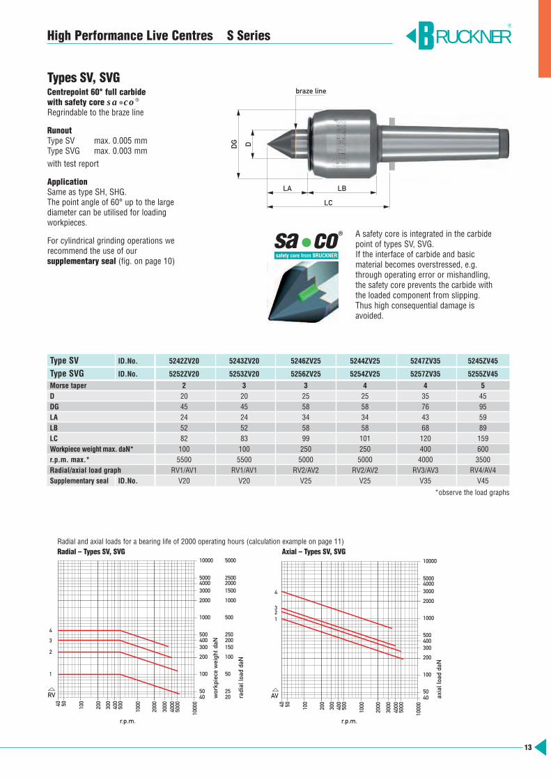
High Performance Live Centres S Series
Types SV, SVGCentrepoint 60° full carbidewith safety core sa•co®
Regrindable to the braze line
RunoutType SV max. 0.005 mmType SVG max. 0.003 mmwith test report
ApplicationSame as type SH, SHG.The point angle of 60° up to the large diameter can be utilised for loading workpieces.
For cylindrical grinding operations werecommend the use of our supplementary seal (fig. on page 10)
Type SV ID.No. 5242ZV20 5243ZV20 5246ZV25 5244ZV25 5247ZV35 5245ZV45
Type SVG ID.No. 5252ZV20 5253ZV20 5256ZV25 5254ZV25 5257ZV35 5255ZV45
Morse taper 2 3 3 4 4 5D 20 20 25 25 35 45DG 45 45 58 58 76 95LA 24 24 34 34 43 59LB 52 52 58 58 68 89LC 82 83 99 101 120 159Workpiece weight max. daN* 100 100 250 250 400 600r.p.m. max.* 5500 5500 5000 5000 4000 3500Radial/axial load graph RV1/AV1 RV1/AV1 RV2/AV2 RV2/AV2 RV3/AV3 RV4/AV4Supplementary seal ID.No. V20 V20 V25 V25 V35 V45
*observe the load graphs
A safety core is integrated in the carbidepoint of types SV, SVG. If the interface of carbide and basic material becomes overstressed, e.g.through operating error or mishandling,the safety core prevents the carbide withthe loaded component from slipping. Thus high consequential damage is avoided.
a co
®s
RUCKNER®
5040 100
200
300
500040
050
0
1000
2000
3000
4000
1000
0
Drehzahl 1/min
10000
500040003000
2000
1000
500400300
200
100
5040
200
2025
100
50
150
250
500
1000
20001500
2500
5000
Rad
ialb
elas
tung
daN
Wer
kstü
ckge
wic
ht d
aN
2
1
3
RV
4
30040 50 100
200
500
400
1000
2000
4000
3000
5000
1000
0
1000
4050
100
200
300400500
3000
2000
50004000
10000
Axi
albe
last
ung
daN
Drehzahl 1/min
AV
3
1
4
2
Radial and axial loads for a bearing life of 2000 operating hours (calculation example on page 11)Radial – Types SV, SVG Axial – Types SV, SVG
LA LB
LC
DG D
braze line
r.p.m. r.p.m.
workpiece weight daN
radial load daN
axial load daN
14
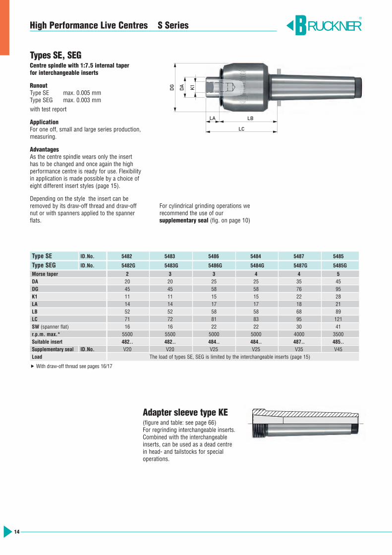
High Performance Live Centres S Series
Types SE, SEGCentre spindle with 1:7.5 internal taper for interchangeable inserts
RunoutType SE max. 0.005 mmType SEG max. 0.003 mmwith test report
ApplicationFor one off, small and large series production,measuring.
AdvantagesAs the centre spindle wears only the insert has to be changed and once again the high performance centre is ready for use. Flexibilityin application is made possible by a choice ofeight different insert styles (page 15).
Depending on the style the insert can beremoved by its draw-off thread and draw-offnut or with spanners applied to the spannerflats.
Type SE ID.No. 5482 5483 5486 5484 5487 5485
Type SEG ID.No. 5482G 5483G 5486G 5484G 5487G 5485G
Morse taper 2 3 3 4 4 5DA 20 20 25 25 35 45DG 45 45 58 58 76 95K1 11 11 15 15 22 28LA 14 14 17 17 18 21LB 52 52 58 58 68 89LC 71 72 81 83 95 121SW (spanner flat) 16 16 22 22 30 41r.p.m. max.* 5500 5500 5000 5000 4000 3500Suitable insert 482.. 482.. 484.. 484.. 487.. 485..Supplementary seal ID.No. V20 V20 V25 V25 V35 V45Load The load of types SE, SEG is limited by the interchangeable inserts (page 15)
With draw-off thread see pages 16/17
RUCKNER®
Adapter sleeve type KE(figure and table: see page 66)For regrinding interchangeable inserts. Combined with the interchangeableinserts, can be used as a dead centre in head- and tailstocks for special operations.
LA LB
LC
DG
DA K1
For cylindrical grinding operations we recommend the use of our supplementary seal (fig. on page 10)
15
High Performance Live Centres S Series
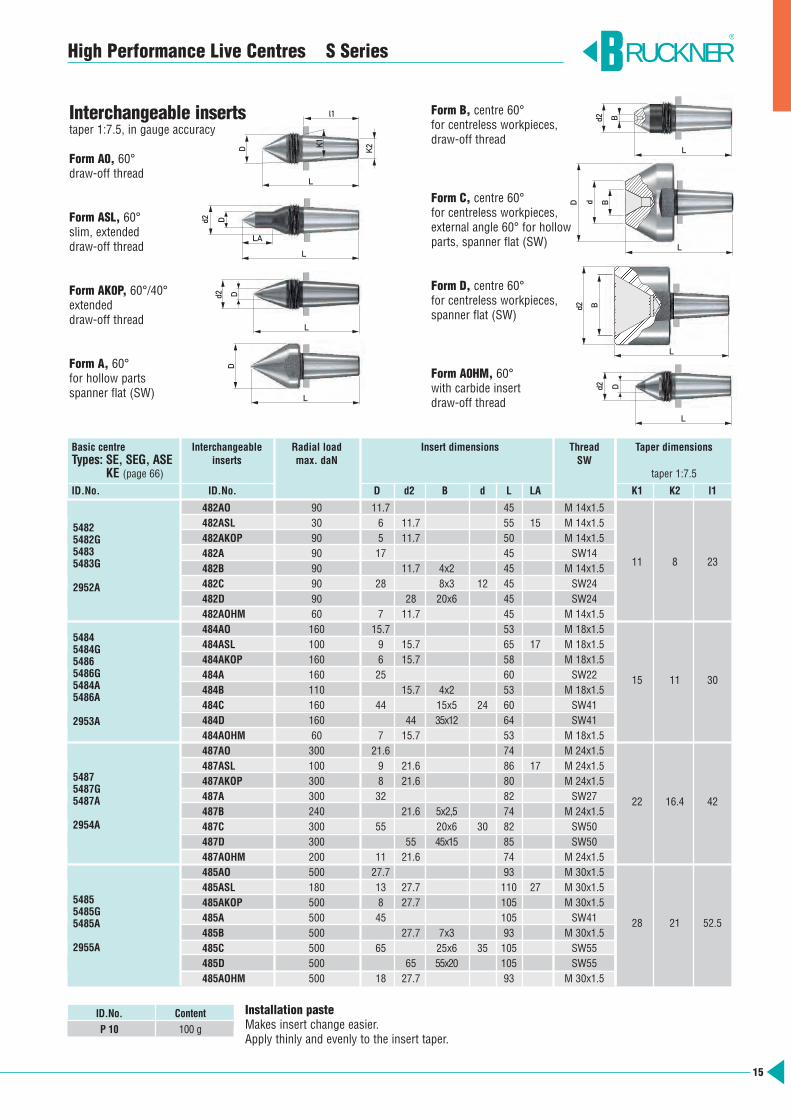
Installation pasteMakes insert change easier.Apply thinly and evenly to the insert taper.
Basic centre Interchangeable Radial load Insert dimensions Thread Taper dimensions Types: SE, SEG, ASE inserts max. daN SW
KE (page 66) taper 1:7.5
ID.No. ID.No. D d2 B d L LA K1 K2 l1
482AO 90 11.7 45 M 14x1.5482ASL 30 6 11.7 55 15 M 14x1.5482AKOP 90 5 11.7 50 M 14x1.5482A 90 17 45 SW14482B 90 11.7 4x2 45 M 14x1.5
11 8 23
482C 90 28 8x3 12 45 SW24482D 90 28 20x6 45 SW24482AOHM 60 7 11.7 45 M 14x1.5484AO 160 15.7 53 M 18x1.5484ASL 100 9 15.7 65 17 M 18x1.5484AKOP 160 6 15.7 58 M 18x1.5484A 160 25 60 SW22 15 11 30484B 110 15.7 4x2 53 M 18x1.5484C 160 44 15x5 24 60 SW41484D 160 44 35x12 64 SW41484AOHM 60 7 15.7 53 M 18x1.5487AO 300 21.6 74 M 24x1.5487ASL 100 9 21.6 86 17 M 24x1.5487AKOP 300 8 21.6 80 M 24x1.5487A 300 32 82 SW27 22 16.4 42487B 240 21.6 5x2,5 74 M 24x1.5487C 300 55 20x6 30 82 SW50487D 300 55 45x15 85 SW50487AOHM 200 11 21.6 74 M 24x1.5485AO 500 27.7 93 M 30x1.5485ASL 180 13 27.7 110 27 M 30x1.5485AKOP 500 8 27.7 105 M 30x1.5485A 500 45 105 SW41 28 21 52.5485B 500 27.7 7x3 93 M 30x1.5485C 500 65 25x6 35 105 SW55485D 500 65 55x20 105 SW55485AOHM 500 18 27.7 93 M 30x1.5
54825482G54835483G
2952A
54845484G54865486G5484A5486A
2953A
54875487G5487A
2954A
54855485G5485A
2955A
ID.No. Content
P 10 100 g
Interchangeable insertstaper 1:7.5, in gauge accuracy
Form A0, 60°draw-off thread
Form ASL, 60°slim, extendeddraw-off thread
Form AK0P, 60°/40°extendeddraw-off thread
Form A, 60°for hollow partsspanner flat (SW)
Form B, centre 60°for centreless workpieces, draw-off thread
Form C, centre 60°for centreless workpieces, external angle 60° for hollowparts, spanner flat (SW)
Form D, centre 60°for centreless workpieces, spanner flat (SW)
Form A0HM, 60°with carbide insertdraw-off thread
RUCKNER®
D
D
Dd2
d2
K2K1
L
LA
L
L
l1
D
L
Bd2
L
L
BdD
B
Dd2
d2
L
L
16
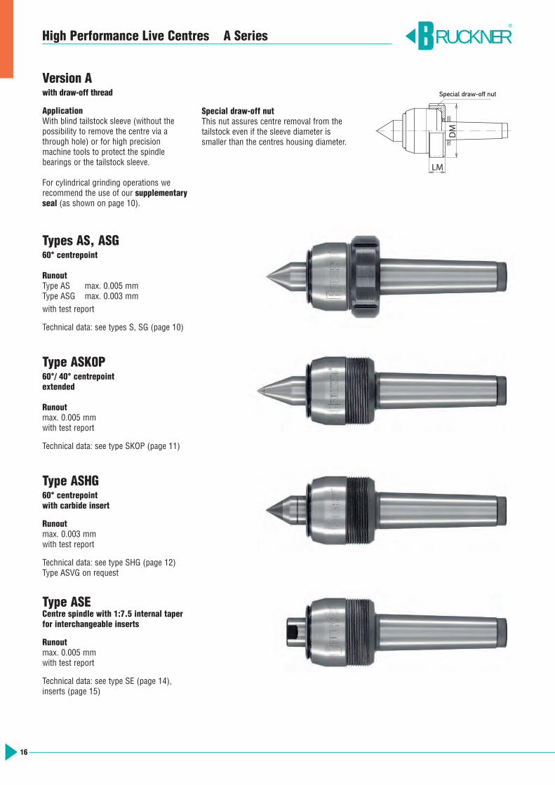
High Performance Live Centres A Series
Version Awith draw-off thread
ApplicationWith blind tailstock sleeve (without thepossibility to remove the centre via athrough hole) or for high precision machine tools to protect the spindle bearings or the tailstock sleeve.
For cylindrical grinding operations werecommend the use of our supplementaryseal (as shown on page 10).
Special draw-off nutThis nut assures centre removal from thetailstock even if the sleeve diameter issmaller than the centres housing diameter.
Types AS, ASG60° centrepoint
RunoutType AS max. 0.005 mmType ASG max. 0.003 mmwith test report
Technical data: see types S, SG (page 10)
Type ASK0P60°/ 40° centrepoint extended
Runoutmax. 0.005 mmwith test report
Technical data: see type SKOP (page 11)
Type ASHG60° centrepoint with carbide insert
Runout max. 0.003 mmwith test report
Technical data: see type SHG (page 12)Type ASVG on request
Type ASECentre spindle with 1:7.5 internal taper for interchangeable inserts
Runoutmax. 0.005 mm with test report
Technical data: see type SE (page 14), inserts (page 15)
LM
DM
Spezialmutter
RUCKNER®
Special draw-off nut

17
High Performance Live Centres A Series
Morse taper 3 4 4 5 6
Type AS ID.No. 5006A 5004A 5007A 5005A 5009Aradial/axial load graph R3/A3 R3/A3 R4/A4 R5/A5 R6/A6
Type ASG ID.No. 5126A 5124A 5127A 5125A 5129Aradial/axial load graph R3/A3 R3/A3 R4/A4 R5/A5 R6/A6
Type ASKOP ID.No. 5366A 5364A 5367A 5365Aradial/axial load graph RK3/A3 RK3/A3 RK4/A4 RK5/A5
Type ASHG ID.No. 5256A 5254A 5257A 5255Aradial/axial load graph RH3/A3 RH3/A3 RH4/A4 RH5/A5
Type ASE ID.No. 5486A 5484A 5487A 5485Aload The load of type ASE is limited by the interchangeable inserts (page 15)
Supplementary seal ID.No. V25 V25 V35 V45 V58
Special nut for version AID.No. M58A M58A M76A M95A M120A
DM 70 70 92 115 138LM 24 24 28 39 45
RUCKNER®
50
40
100
200
300
5000
400
500
1000
2000
3000
40
00
1000
0
10000
5000 4000 3000
2000
1000
500 400 300
200
100
50 40
200
20 25
100
50
150
250
500
1000
2000 1500
2500
5000
Rad
ialb
elas
tung
daN
Wer
kstü
ckge
wic
ht d
aN
Drehzahl 1/min
3
4
RH
5
30040 50 100
200
500
400
1000
2000
4000
3000
5000
1000
0
1000
4050
100
200
300400500
3000
2000
50004000
10000
Axi
albe
last
ung
daN
Drehzahl 1/min
A
4
5
3
6
Radial – Type ASHG Axial – all A Types
5040 100
200
300
5000400
500
1000
2000
3000
4000
1000
0
Drehzahl 1/min
10000
500040003000
2000
1000
500400300
200
100
5040
200
2025
100
50
150
250
500
1000
20001500
2500
5000
Rad
ialb
elas
tung
daN
Wer
kstü
ckge
wic
ht d
aN
3
4
R
6
5
50
40
100
200
300
5000
400
500
1000
2000
3000
40
00
1000
0
Drehzahl 1/min
10000
5000 4000 3000
2000
1000
500 400 300
200
100
50 40
200
20 25
100
50
150
250
500
1000
2000 1500
2500
5000
Rad
ialb
elas
tung
daN
Wer
kstü
ckge
wic
ht d
aN
3
4
RK
5
Radial and axial loads for a bearing life of 2000 operating hours (calculation example on page 11)Radial – Types AS, ASG Radial – Type ASKOP
r.p.m. r.p.m.
r.p.m. r.p.m.
workpiece weight daN
radial load daN
workpiece weight daN
radial load daN
workpiece weight daN
radial load daN
axial load daN
18
RUCKNER®
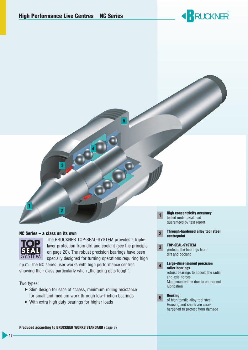
High concentricity accuracytested under axial loadguaranteed by test report
Through-hardened alloy tool steelcentrepoint
TOP-SEAL-SYSTEMprotects the bearings from dirt and coolant
Large-dimensioned precision roller bearingsrobust bearings to absorb the radial and axial forces. Maintenance-free due to permanent lubrication
Housingof high tensile alloy tool steel. Housing and shank are case-hardened to protect from damage
NC Series – a class on its ownThe BRUCKNER TOP-SEAL-SYSTEM provides a triple-layer protection from dirt and coolant (see the principle on page 20). The robust precision bearings have been specially designed for turning operations requiring high
r.p.m. The NC series user works with high performance centres showing their class particularly when „the going gets tough“.
Two types: Slim design for ease of access, minimum rolling resistance for small and medium work through low-friction bearings
With extra high duty bearings for higher loads
SYSTEM
TOPSEAL
High Performance Live Centres NC Series
1
2
3
4
5
12
3
4
5
Produced according to BRUCKNER WORKS STANDARD (page 8)
19
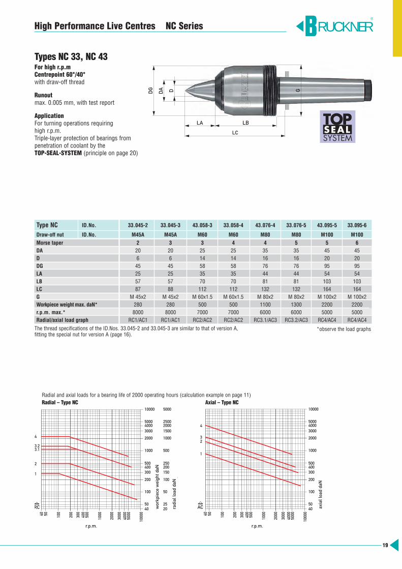
Types NC 33, NC 43For high r.p.mCentrepoint 60°/40°with draw-off thread
Runoutmax. 0.005 mm, with test report
ApplicationFor turning operations requiring high r.p.m.Triple-layer protection of bearings frompenetration of coolant by the TOP-SEAL-SYSTEM (principle on page 20)
High Performance Live Centres NC Series
Type NC ID.No. 33.045-2 33.045-3 43.058-3 33.058-4 43.076-4 33.076-5 43.095-5 33.095-6
Draw-off nut ID.No. M45A M45A M60 M60 M80 M80 M100 M100
Morse taper 2 3 3 4 4 5 5 6DA 20 20 25 25 35 35 45 45D 6 6 14 14 16 16 20 20DG 45 45 58 58 76 76 95 95LA 25 25 35 35 44 44 54 54LB 57 57 70 70 81 81 103 103LC 87 88 112 112 132 132 164 164G M 45x2 M 45x2 M 60x1.5 M 60x1.5 M 80x2 M 80x2 M 100x2 M 100x2Workpiece weight max. daN* 280 280 500 500 1100 1300 2200 2200r.p.m. max.* 8000 8000 7000 7000 6000 6000 5000 5000Radial/axial load graph RC1/AC1 RC1/AC1 RC2/AC2 RC2/AC2 RC3.1/AC3 RC3.2/AC3 RC4/AC4 RC4/AC4
The thread specifications of the ID.Nos. 33.045-2 and 33.045-3 are similar to that of version A, fitting the special nut for version A (page 16).
RUCKNER®
50
40
100
200
300
5000
400
500
1000
2000
3000
40
00
1000
0
Drehzahl 1/min
10000
5000 4000 3000
2000
1000
500 400 300
200
100
50 40
200
20 25
100
50
150
250
500
1000
2000 1500
2500
5000
Rad
ialb
elas
tung
daN
Wer
kstü
ckge
wic
ht d
aN
4
3.1
2
1
RC
3.2
300 40
50
100
200
500
400
1000
2000
4000
30
00
5000
1000
0
1000
40 50
100
200
300 400 500
3000
2000
5000 4000
10000
Axi
albe
last
ung
daN
Drehzahl 1/min
AC
4
2
1
3
Radial and axial loads for a bearing life of 2000 operating hours (calculation example on page 11)Radial – Type NC Axial – Type NC
DG
DA
LA LB
LC
D G
SYSTEM
TOPSEAL
*observe the load graphs
r.p.m. r.p.m.
workp
iece w
eigh
t daN
radial lo
ad daN
axial loa
d da
N
20
High Performance Live Centres NC Series
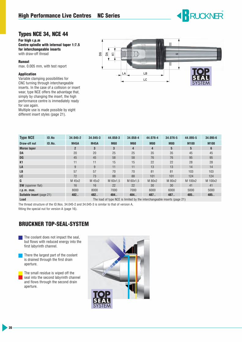
Types NCE 34, NCE 44For high r.p.mCentre spindle with internal taper 1:7.5for interchangeable insertswith draw-off thread
Runoutmax. 0.005 mm, with test report
ApplicationVariable clamping possibilities for CNC turning through interchangeableinserts. In the case of a collision or insertwear, type NCE offers the advantage that,simply by changing the insert, the highperformance centre is immediately readyfor use again. Multiple use is made possible by eight different insert styles (page 21).
Type NCE ID.No 34.045-2 34.045-3 44.058-3 34.058-4 44.076-4 34.076-5 44.095-5 34.095-6
Draw-off nut ID.No. M45A M45A M60 M60 M80 M80 M100 M100
Morse taper 2 3 3 4 4 5 5 6DA 20 20 25 25 35 35 45 45DG 45 45 58 58 76 76 95 95K1 11 11 15 15 22 22 28 28LA 9 9 11 11 13 13 14 14LB 57 57 70 70 81 81 103 103LC 72 73 88 88 101 101 124 124G M 45x2 M 45x2 M 60x1,5 M 60x1,5 M 80x2 M 80x2 M 100x2 M 100x2SW (spanner flat) 16 16 22 22 30 30 41 41r.p.m. max. 8000 8000 7000 7000 6000 6000 5000 5000Suitable insert (page 21) 482.. 482.. 484.. 484.. 487.. 487.. 485.. 485..Load The load of type NCE is limited by the interchangeable inserts (page 21)
The thread structure of the ID.Nos. 34.045-2 and 34.045-3 is similar to that of version A, fitting the special nut for version A (page 16).
The coolant does not impact the seal,but flows with reduced energy into thefirst labyrinth channel.
There the largest part of the coolant is drained through the first drain aperture.
The small residue is wiped off the seal into the second labyrinth channeland flows through the second drain aperture.
SYSTEM
TOPSEAL
RUCKNER®
LA LB
LC
DG
DA K1 G
SYSTEM
TOPSEAL
BRUCKNER TOP-SEAL-SYSTEM
21
High Performance Live Centres NC Series RUCKNER®
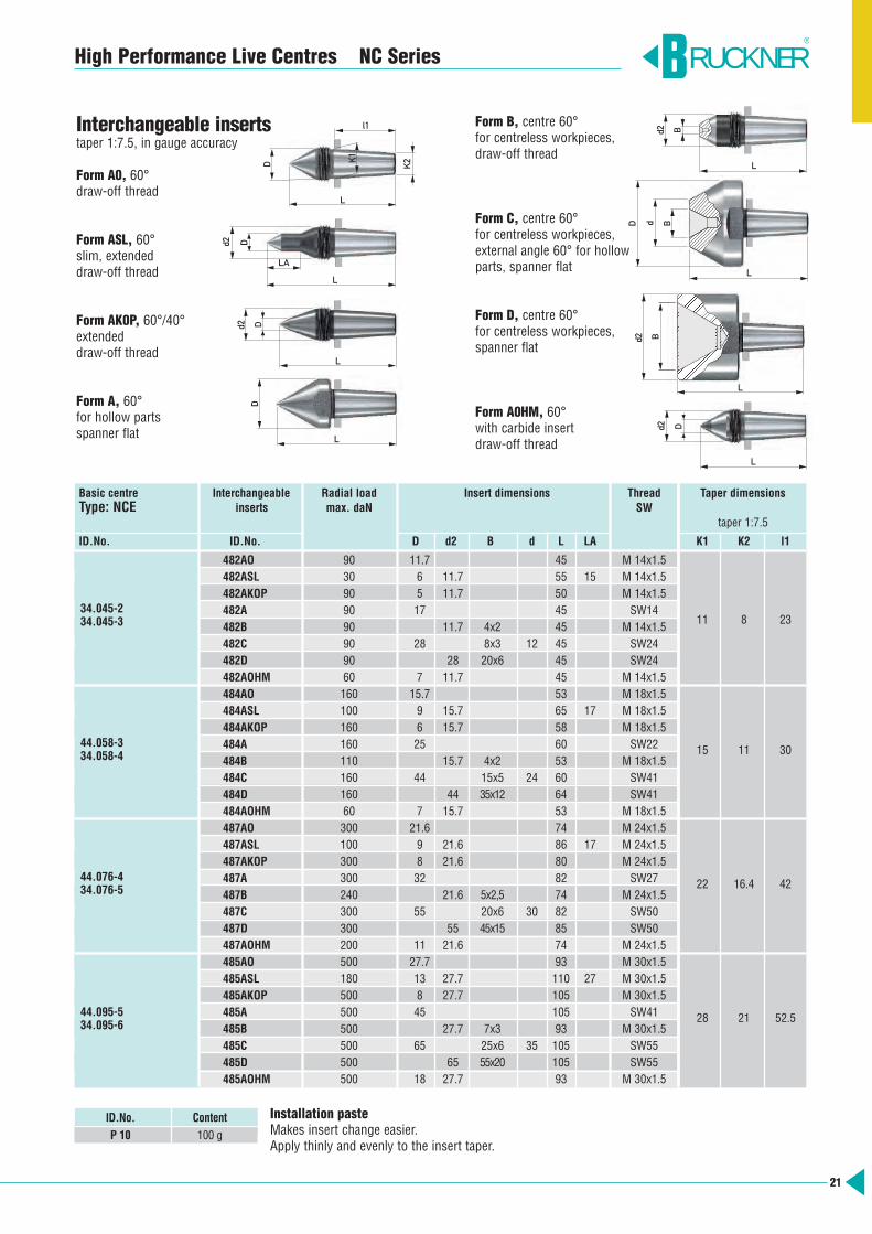
Installation pasteMakes insert change easier.Apply thinly and evenly to the insert taper.
Basic centre Interchangeable Radial load Insert dimensions Thread Taper dimensions Type: NCE inserts max. daN SW
taper 1:7.5
ID.No. ID.No. D d2 B d L LA K1 K2 l1
482AO 90 11.7 45 M 14x1.5482ASL 30 6 11.7 55 15 M 14x1.5482AKOP 90 5 11.7 50 M 14x1.5482A 90 17 45 SW14482B 90 11.7 4x2 45 M 14x1.5
11 8 23
482C 90 28 8x3 12 45 SW24482D 90 28 20x6 45 SW24482AOHM 60 7 11.7 45 M 14x1.5484AO 160 15.7 53 M 18x1.5484ASL 100 9 15.7 65 17 M 18x1.5484AKOP 160 6 15.7 58 M 18x1.5484A 160 25 60 SW22 15 11 30484B 110 15.7 4x2 53 M 18x1.5484C 160 44 15x5 24 60 SW41484D 160 44 35x12 64 SW41484AOHM 60 7 15.7 53 M 18x1.5487AO 300 21.6 74 M 24x1.5487ASL 100 9 21.6 86 17 M 24x1.5487AKOP 300 8 21.6 80 M 24x1.5487A 300 32 82 SW27 22 16.4 42487B 240 21.6 5x2,5 74 M 24x1.5487C 300 55 20x6 30 82 SW50487D 300 55 45x15 85 SW50487AOHM 200 11 21.6 74 M 24x1.5485AO 500 27.7 93 M 30x1.5485ASL 180 13 27.7 110 27 M 30x1.5485AKOP 500 8 27.7 105 M 30x1.5485A 500 45 105 SW41 28 21 52.5485B 500 27.7 7x3 93 M 30x1.5485C 500 65 25x6 35 105 SW55485D 500 65 55x20 105 SW55485AOHM 500 18 27.7 93 M 30x1.5
34.045-234.045-3
44.058-334.058-4
44.076-434.076-5
44.095-534.095-6
ID.No. Content
P 10 100 g
Interchangeable insertstaper 1:7.5, in gauge accuracy
Form A0, 60°draw-off thread
Form ASL, 60°slim, extendeddraw-off thread
Form AK0P, 60°/40°extendeddraw-off thread
Form A, 60°for hollow partsspanner flat
Form B, centre 60°for centreless workpieces, draw-off thread
Form C, centre 60°for centreless workpieces, external angle 60° for hollowparts, spanner flat
Form D, centre 60°for centreless workpieces, spanner flat
Form A0HM, 60°with carbide insertdraw-off thread
D
D
Dd2
d2
K2K1
L
LA
L
L
l1
D
L
Bd2
L
L
BdD
B
Dd2
d2
L
L
22
RUCKNER®
High Performance Live Centres LK Series
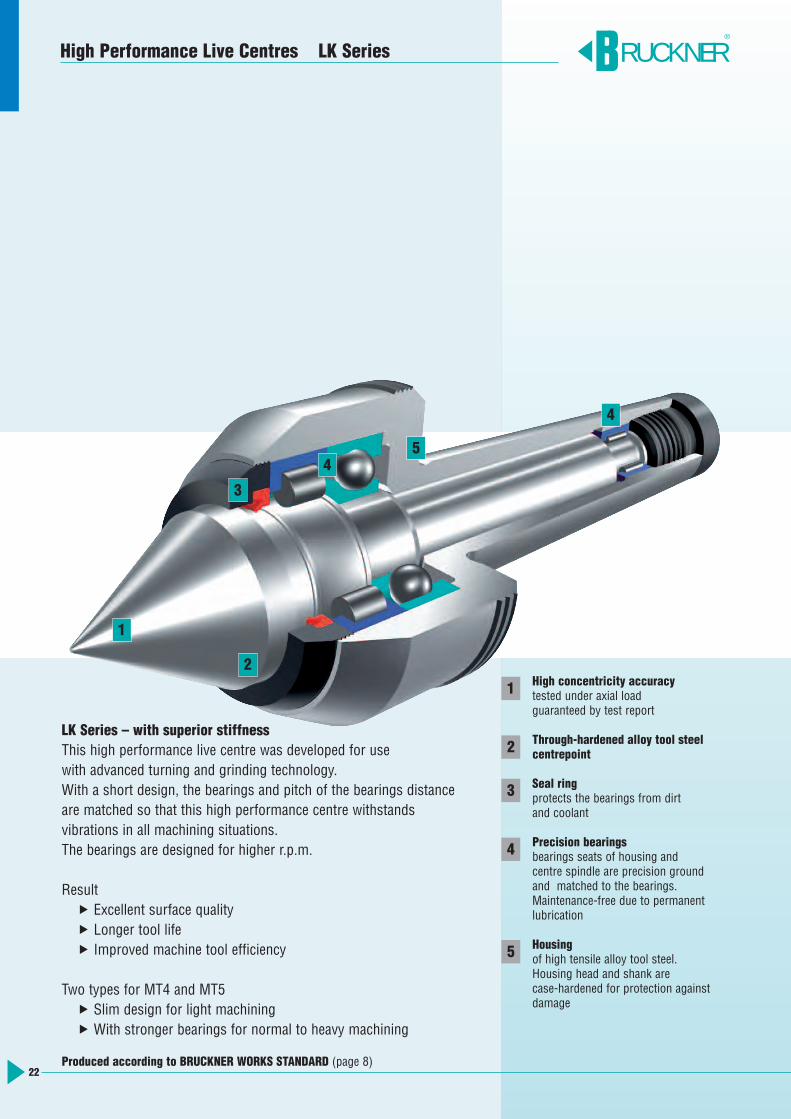
High concentricity accuracytested under axial loadguaranteed by test report
Through-hardened alloy tool steelcentrepoint
Seal ringprotects the bearings from dirt and coolant
Precision bearingsbearings seats of housing and centre spindle are precision groundand matched to the bearings. Maintenance-free due to permanent lubrication
Housingof high tensile alloy tool steel. Housing head and shank are case-hardened for protection againstdamage
1
2
3
4
5
LK Series – with superior stiffnessThis high performance live centre was developed for usewith advanced turning and grinding technology.With a short design, the bearings and pitch of the bearings distance are matched so that this high performance centre withstands vibrations in all machining situations.The bearings are designed for higher r.p.m.
Result Excellent surface quality Longer tool life Improved machine tool efficiency
Two types for MT4 and MT5 Slim design for light machining With stronger bearings for normal to heavy machining
1
2
3
4
4
5
Produced according to BRUCKNER WORKS STANDARD (page 8)
23
High Performance Live Centres LK Series
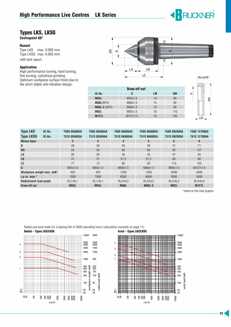
Types LKS, LKSGCentrepoint 60°
RunoutType LKS max. 0.005 mmType LKSG max. 0.003 mmwith test report
ApplicationHigh performance turning, hard turning, fine turning, cylindrical grinding. Optimum workpiece surface finish due tothe short stable anti-vibration design.
Type LKS ID.No. 750S 055003A 750S 055004A 750S 068004A 750S 068005A 750S 092005A 750S 127006A
Type LKSG ID.No. 751S 055003A 751S 055004A 751S 068004A 751S 068005A 751S 092005A 751S 127006A
Morse taper 3 4 4 5 5 6D 26 26 36 36 51 71DG 55 55 68 68 92 127LA 26 26 35 35 47 65LB 41 41 51,5 51,5 60 80LC 71 72 92 92 113 152G M55x1.5 M55x1.5 M68x1.5 M68x1.5 M92x1.5 M127x1.5Workpiece weight max. daN* 420 420 1200 1200 2000 4400r.p.m. max.* 7000 7000 6000 6000 5000 3000Radial/axial load graph RL1/AL1 RL1/AL1 RL2/AL2 RL2/AL2 RL3/AL3 RL4/AL4Draw-off nut M55L M55L M68L M68L-5 M92L M127L
*observe the load graphs
ID.No. G LM DM
M55L M55x1.5 10 68M68L(MT4) M68x1.5 15 80M68L-5 (MT5) M68x1.5 15 80M92L M92x1.5 18 110M127L M127x1.5 18 145
Draw-off nut
LM
G
DM
RUCKNER®
5040 100
200
300
500040
050
0
1000
2000
3000
4000
1000
0
Drehzahl 1/min
3
2
1
10000
500040003000
2000
1000
500400300
200
100
5040
200
2025
100
50
150
250
500
1000
20001500
2500
5000
Rad
ialb
elas
tung
daN
Wer
kstü
ckge
wic
ht d
aN
4
RL
30040 50 100
200
500
400
1000
2000
4000
3000
5000
1000
0
1000
4050
100
200
300400500
3000
2000
50004000
10000
Axi
albe
last
ung
daN
Drehzahl 1/min
AL
3
2
1
4
Radial and axial loads for a bearing life of 2000 operating hours (calculation example on page 11)Radial – Types LKS/LKSG Axial – Types LKS/LKSG
D GDG
LBLA
LCNut 4x90°
r.p.m. r.p.m.
workp
iece w
eigh
t daN
radial lo
ad daN
axial loa
d da
N
24
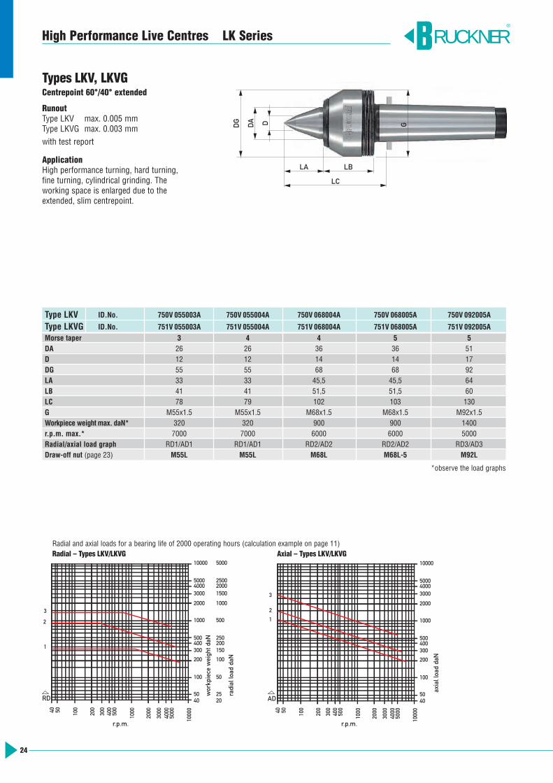
Types LKV, LKVGCentrepoint 60°/40° extended
RunoutType LKV max. 0.005 mmType LKVG max. 0.003 mmwith test report
ApplicationHigh performance turning, hard turning, fine turning, cylindrical grinding. The working space is enlarged due to theextended, slim centrepoint.
Type LKV ID.No. 750V 055003A 750V 055004A 750V 068004A 750V 068005A 750V 092005A
Type LKVG ID.No. 751V 055003A 751V 055004A 751V 068004A 751V 068005A 751V 092005A
Morse taper 3 4 4 5 5DA 26 26 36 36 51D 12 12 14 14 17DG 55 55 68 68 92LA 33 33 45,5 45,5 64LB 41 41 51,5 51,5 60LC 78 79 102 103 130G M55x1.5 M55x1.5 M68x1.5 M68x1.5 M92x1.5Workpiece weight max. daN* 320 320 900 900 1400r.p.m. max.* 7000 7000 6000 6000 5000Radial/axial load graph RD1/AD1 RD1/AD1 RD2/AD2 RD2/AD2 RD3/AD3Draw-off nut (page 23) M55L M55L M68L M68L-5 M92L
*observe the load graphs
High Performance Live Centres LK Series RUCKNER®
5040 100
200
300
500040
050
0
1000
2000
3000
4000
1000
0
Drehzahl 1/min
10000
500040003000
2000
1000
500400300
200
100
5040
200
2025
100
50
150
250
500
1000
20001500
2500
5000
Rad
ialb
elas
tung
daN
Wer
kstü
ckge
wic
ht d
aN
3
2
1
RD
30040 50 100
200
500
400
1000
2000
4000
3000
5000
1000
0
1000
4050
100
200
300400500
3000
2000
50004000
10000
Axi
albe
last
ung
daN
Drehzahl 1/min
AD
3
2
1
Radial and axial loads for a bearing life of 2000 operating hours (calculation example on page 11)Radial – Types LKV/LKVG Axial – Types LKV/LKVG
D GDA
DG
LBLA
LC
r.p.m. r.p.m.
workp
iece w
eigh
t daN
radial lo
ad daN
axial loa
d da
N
High Performance Live Centres LK Series
25
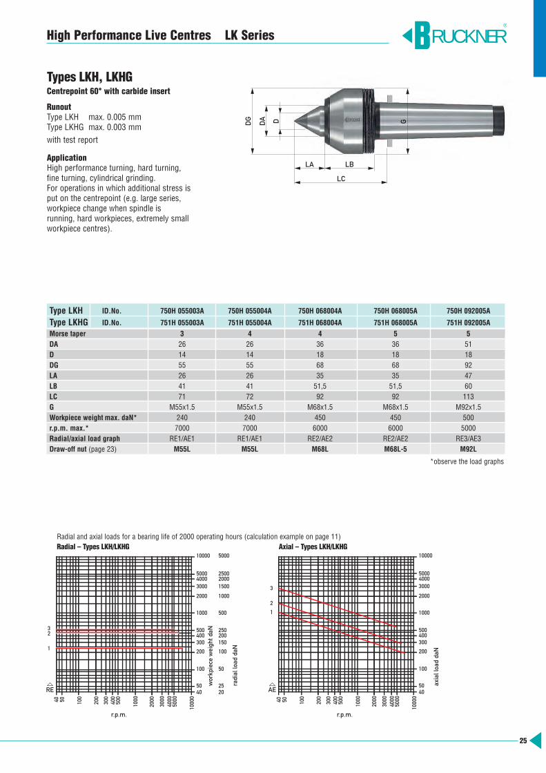
Types LKH, LKHGCentrepoint 60° with carbide insert
RunoutType LKH max. 0.005 mmType LKHG max. 0.003 mmwith test report
ApplicationHigh performance turning, hard turning, fine turning, cylindrical grinding. For operations in which additional stress isput on the centrepoint (e.g. large series,workpiece change when spindle is running, hard workpieces, extremely smallworkpiece centres).
Type LKH ID.No. 750H 055003A 750H 055004A 750H 068004A 750H 068005A 750H 092005A
Type LKHG ID.No. 751H 055003A 751H 055004A 751H 068004A 751H 068005A 751H 092005A
Morse taper 3 4 4 5 5DA 26 26 36 36 51D 14 14 18 18 18DG 55 55 68 68 92LA 26 26 35 35 47LB 41 41 51,5 51,5 60LC 71 72 92 92 113G M55x1.5 M55x1.5 M68x1.5 M68x1.5 M92x1.5Workpiece weight max. daN* 240 240 450 450 500r.p.m. max.* 7000 7000 6000 6000 5000Radial/axial load graph RE1/AE1 RE1/AE1 RE2/AE2 RE2/AE2 RE3/AE3Draw-off nut (page 23) M55L M55L M68L M68L-5 M92L
*observe the load graphs
RUCKNER®
D GDA
DG
LBLA
LC
5040 100
200
300
5000400
500
1000
2000
3000
4000
1000
0
Drehzahl 1/min
10000
500040003000
2000
1000
500400300
200
100
5040
200
2025
100
50
150
250
500
1000
20001500
2500
5000
Rad
ialb
elas
tung
daN
Wer
kstü
ckge
wic
ht d
aN
2
1
RE
3
300
40 50 100
200
500
400
1000
2000
4000
3000
5000
1000
0
1000
4050
100
200
300400500
3000
2000
50004000
10000
Axi
albe
last
ung
daN
Drehzahl 1/min
AE
3
2
1
Radial and axial loads for a bearing life of 2000 operating hours (calculation example on page 11)Radial – Types LKH/LKHG Axial – Types LKH/LKHG
r.p.m. r.p.m.
workp
iece w
eigh
t daN
radial lo
ad daN
axial loa
d da
N
LA LB
LC
DG D
26
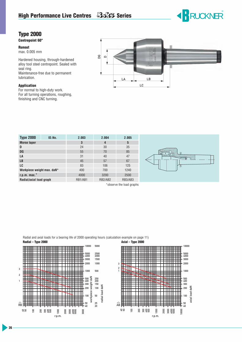
Type 2000 ID.No. 2.003 2.004 2.005
Morse taper 3 4 5D 24 30 35DG 55 70 85LA 31 40 47LB 45 57 67LC 83 106 125Workpiece weight max. daN* 400 700 1240
r.p.m. max.* 4000 3200 2500Radial/axial load graph RB1/AB1 RB2/AB2 RB3/AB3
*observe the load graphs
RUCKNER®
5040 100
200
300
500040
050
0
1000
2000
3000
4000
1000
0
Drehzahl 1/min
10000
500040003000
2000
1000
500400300
200
100
5040
200
2025
100
50
150
250
500
1000
20001500
2500
5000
Rad
ialb
elas
tung
daN
Wer
kstü
ckge
wic
ht d
aN
3
2
1
RB
30040 50 100
200
500
400
1000
2000
4000
3000
5000
1000
0
1000
4050
100
200
300400500
3000
2000
50004000
10000
Axi
albe
last
ung
daN
Drehzahl 1/min
AB
21
3
Radial and axial loads for a bearing life of 2000 operating hours (calculation example on page 11)Radial – Type 2000 Axial – Type 2000
High Performance Live Centres Series
Type 2000Centrepoint 60°
Runoutmax. 0.005 mm
Hardened housing, through-hardened alloy tool steel centrepoint. Sealed withseal ring. Maintenance-free due to permanent lubrication.
ApplicationFor normal to high-duty work.For all turning operations, roughing, finishing and CNC turning.
r.p.m. r.p.m.
workp
iece w
eigh
t daN
radial lo
ad daN
axial loa
d da
N
27
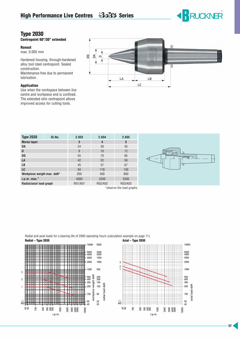
High Performance Live Centres Series
Type 2030Centrepoint 60°/30° extended
Runoutmax. 0.005 mm
Hardened housing, through-hardenedalloy tool steel centrepoint. Sealed construction. Maintenance-free due to permanent lubrication.
ApplicationUse when the workspace between livecentre and workpiece end is confined. The extended slim centrepoint allowsimproved access for cutting tools.
Type 2030 ID.No. 2.033 2.034 2.035
Morse taper 3 4 5DA 24 30 35D 8 10 12DG 55 70 85LA 42 52 58LB 45 57 67LC 94 118 136Workpiece weight max. daN* 200 400 800
r.p.m. max.* 4000 3200 2500Radial/axial load graph R01/A01 R02/A02 R03/A03
*observe the load graphs
RUCKNER®
5040 100
200
300
500040
050
0
1000
2000
3000
4000
1000
0
Drehzahl 1/min
10000
500040003000
2000
1000
500400300
200
100
5040
200
2025
100
50
150
250
500
1000
20001500
2500
5000
Rad
ialb
elas
tung
daN
Wer
kstü
ckge
wic
ht d
aN
3
2
1
RO
30040 50 100
200
500
400
1000
2000
4000
3000
5000
1000
0
1000
4050
100
200
300400500
3000
2000
50004000
10000
Axi
albe
last
ung
daN
Drehzahl 1/min
AO
21
3
Radial and axial loads for a bearing life of 2000 operating hours (calculation example on page 11)Radial – Type 2030 Axial – Type 2030
DG DA D
LA LB
LC
r.p.m. r.p.m.
workp
iece w
eigh
t daN
radial lo
ad daN
axial loa
d da
N
28
example of function for design line LR
low clamping forceReduction of spring force through soft springon request
medium clamping force high clamping force
axial force per coloured ring
Morsetaper axial force daN
3 0 - 250 250 - 500 500 - 8504 0 - 350 350 - 620 620 - 8505 0 - 570 570 - 1000 1000 - 13606 0 - 1700 1700 - 3200 3200 - 4600
RUCKNER®
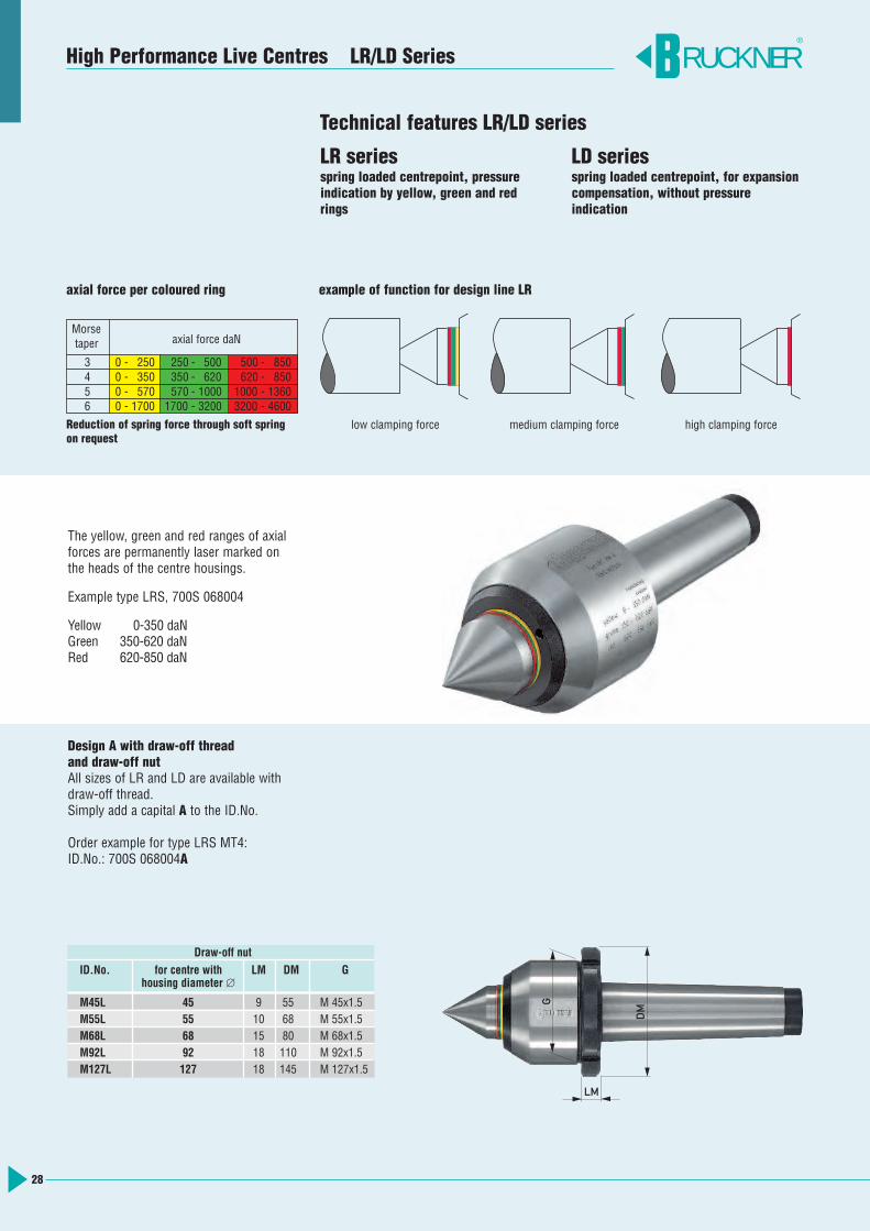
Technical features LR/LD series
LR seriesspring loaded centrepoint, pressureindication by yellow, green and redrings
LD seriesspring loaded centrepoint, for expansion compensation, without pressure indication
The yellow, green and red ranges of axialforces are permanently laser marked onthe heads of the centre housings.
Example type LRS, 700S 068004
Yellow 0-350 daNGreen 350-620 daNRed 620-850 daN
Design A with draw-off thread and draw-off nutAll sizes of LR and LD are available withdraw-off thread.Simply add a capital A to the ID.No.
Order example for type LRS MT4:ID.No.: 700S 068004A
DM
G
LM
High Performance Live Centres LR/LD Series
Draw-off nut
ID.No. for centre with LM DM Ghousing diameter ∅
M45L 45 9 55 M 45x1.5M55L 55 10 68 M 55x1.5M68L 68 15 80 M 68x1.5M92L 92 18 110 M 92x1.5M127L 127 18 145 M 127x1.5
29
RUCKNER®
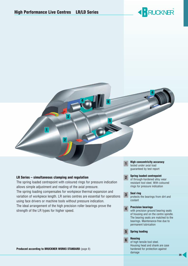
LR Series – simultaneous clamping and regulationThe spring loaded centrepoint with coloured rings for pressure indication allows simple adjustment and reading of the axial pressure.The spring loading compensates for workpiece thermal expansion and variation of workpiece length. LR series centres are essential for operationsusing face drivers or machine tools without pressure indication. The ideal arrangement of the high precision roller bearings prove thestrength of the LR types for higher speed.
High concentricity accuracytested under axial loadguaranteed by test report
Spring loaded centrepointof through-hardened alloy wear resistant tool steel. With colouredrings for pressure indication
Seal ringprotects the bearings from dirt andcoolant
Precision bearingswith precision ground bearing seatsof housing and on the centre spindle. The bearing seats are matched to thebearings. Maintenance-free due to permanent lubrication
Spring loading
Housingof high tensile tool steel. Housing head and shank are casehardened for protection against damage
1
2
3
4
5
6
High Performance Live Centres LR/LD Series
1
2
3
4
4
5
6
Produced according to BRUCKNER WORKS STANDARD (page 8)
30
High Performance Live Centres LR Series RUCKNER®
5040 100
200
300
500040
050
0
1000
2000
3000
4000
1000
0
Drehzahl 1/min
3
2
1
10000
500040003000
2000
1000
500400300
200
100
5040
200
2025
100
50
150
250
500
1000
20001500
2500
5000
Rad
ialb
elas
tung
daN
Wer
kstü
ckge
wic
ht d
aN
4
RR
30040 50 100
200
500
400
1000
2000
4000
3000
5000
1000
0
1000
4050
100
200
300400500
3000
2000
50004000
10000
Axi
albe
last
ung
daN
Drehzahl 1/min
AR
3
2
1
4
Radial and axial loads for a bearing life of 2000 operating hours (calculation example on page 11)Radial – Types LRS, LRSG Axial – Types LRS, LRSG
LA
LC
LB
DG D
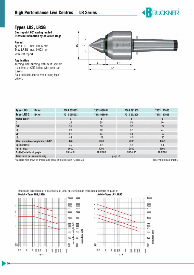
Types LRS, LRSGCentrepoint 60° spring loaded Pressure indication by coloured rings
RunoutType LRS max. 0.005 mmType LRSG max. 0.003 mmwith test report
ApplicationTurning, CNC turning with multi-spindlemachines or CNC lathes with twin tool turrets.As a tailstock centre when using face drivers
Type LRS ID.No. 700S 055003 700S 068004 700S 092005 700S 127006
Type LRSG ID.No. 701S 055003 701S 068004 701S 092005 701S 127006
Morse taper 3 4 5 6D 25 35 50 70DG 55 68 92 127LA 28 40 57 74LB 51 63 82 109LC 84 108 145 190Max. workpiece weight max daN* 420 1200 2000 4400Spring travel 2.7 4.2 5.4 8.4r.p.m. max.* 5000 4000 3500 2300Radial/axial load graph RR1/AR1 RR2/AR2 RR3/AR3 RR4/AR4Axial force per coloured ring page 28Available with draw-off thread and draw-off nut (design A, page 28) *observe the load graphs
r.p.m. r.p.m.
workpiece weight daN
radial load daN
axial load daN
5040 100
200
300
5000400
500
1000
2000
3000
4000
1000
0
Drehzahl 1/min
10000
500040003000
2000
1000
500400300
200
100
5040
200
2025
100
50
150
250
500
1000
20001500
2500
5000
Rad
ialb
elas
tung
daN
Wer
kstü
ckge
wic
ht d
aN
3
2
1
RF
30040 50 100
200
500
400
1000
2000
4000
3000
5000
1000
0
1000
4050
100
200
300400500
3000
2000
50004000
10000
Axi
albe
last
ung
daN
Drehzahl 1/min
AF
2
1
3
Radial and axial loads for a bearing life of 2000 operating hours (calculation example on page 11)Radial – Type LRV Axial – Type LRV
31
High Performance Live Centres LR Series
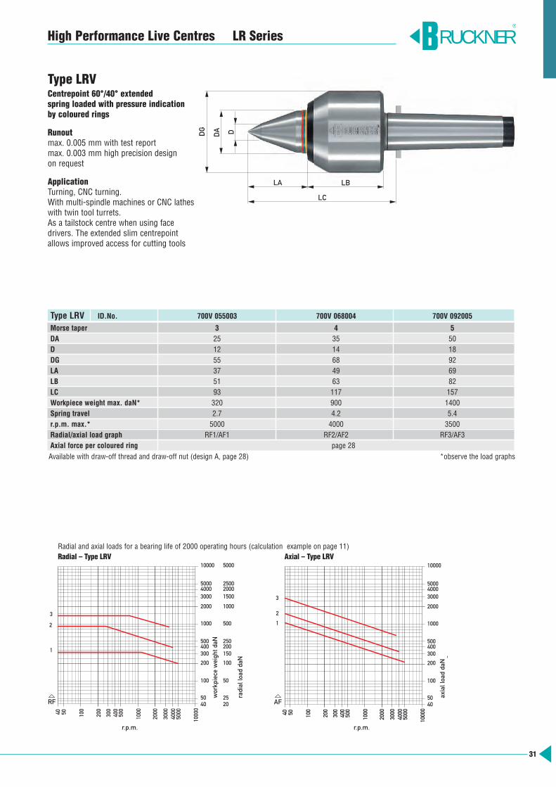
Type LRVCentrepoint 60°/40° extended spring loaded with pressure indication by coloured rings
Runoutmax. 0.005 mm with test report max. 0.003 mm high precision design on request
ApplicationTurning, CNC turning. With multi-spindle machines or CNC lathes with twin tool turrets.As a tailstock centre when using face drivers. The extended slim centrepointallows improved access for cutting tools
Type LRV ID.No. 700V 055003 700V 068004 700V 092005
Morse taper 3 4 5DA 25 35 50D 12 14 18DG 55 68 92LA 37 49 69LB 51 63 82LC 93 117 157Workpiece weight max. daN* 320 900 1400Spring travel 2.7 4.2 5.4r.p.m. max.* 5000 4000 3500Radial/axial load graph RF1/AF1 RF2/AF2 RF3/AF3Axial force per coloured ring page 28Available with draw-off thread and draw-off nut (design A, page 28) *observe the load graphs
RUCKNER®
LA
LC
LB
DG
DA D
r.p.m. r.p.m.
workpiece weight daN
radial load daN
axial load daN
32
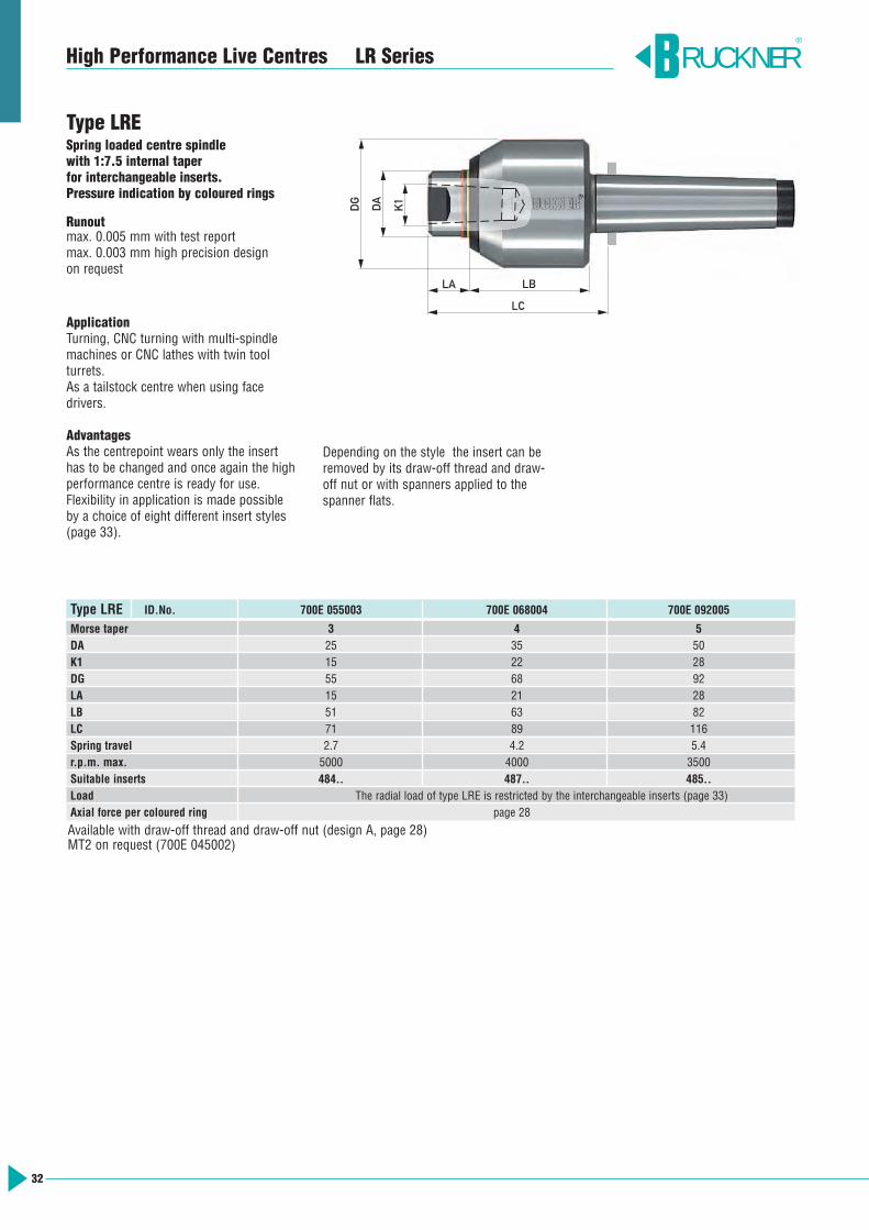
Type LRESpring loaded centre spindle with 1:7.5 internal taper for interchangeable inserts. Pressure indication by coloured rings
Runoutmax. 0.005 mm with test report max. 0.003 mm high precision design on request
ApplicationTurning, CNC turning with multi-spindlemachines or CNC lathes with twin tool turrets.As a tailstock centre when using face drivers.
AdvantagesAs the centrepoint wears only the inserthas to be changed and once again the highperformance centre is ready for use.Flexibility in application is made possibleby a choice of eight different insert styles(page 33).
Type LRE ID.No. 700E 055003 700E 068004 700E 092005
Morse taper 3 4 5DA 25 35 50K1 15 22 28DG 55 68 92LA 15 21 28LB 51 63 82LC 71 89 116Spring travel 2.7 4.2 5.4r.p.m. max. 5000 4000 3500Suitable inserts 484.. 487.. 485..Load The radial load of type LRE is restricted by the interchangeable inserts (page 33)Axial force per coloured ring page 28
Available with draw-off thread and draw-off nut (design A, page 28)MT2 on request (700E 045002)
RUCKNER®
LA
LC
LB
DG
DA
K1
High Performance Live Centres LR Series
Depending on the style the insert can beremoved by its draw-off thread and draw-off nut or with spanners applied to thespanner flats.
33
High Performance Live Centres LR Series RUCKNER®
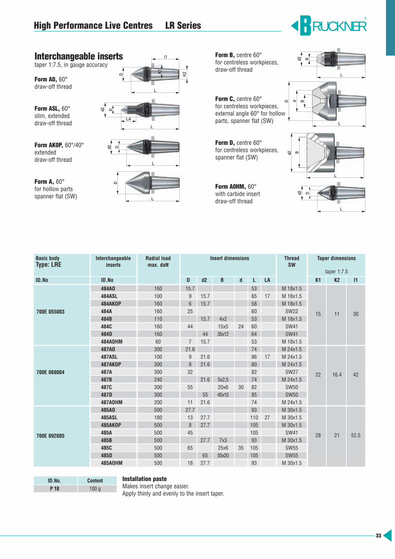
Installation pasteMakes insert change easier.Apply thinly and evenly to the insert taper.
ID.No. Content
P 10 100 g
Basic body Interchangeable Radial load Insert dimensions Thread Taper dimensions Type: LRE inserts max. daN SW
taper 1:7.5
ID.No ID.No D d2 B d L LA K1 K2 l1
484AO 160 15.7 53 M 18x1.5484ASL 100 9 15.7 65 17 M 18x1.5484AKOP 160 6 15.7 58 M 18x1.5484A 160 25 60 SW22 15 11 30484B 110 15.7 4x2 53 M 18x1.5484C 160 44 15x5 24 60 SW41484D 160 44 35x12 64 SW41484AOHM 60 7 15.7 53 M 18x1.5487AO 300 21.6 74 M 24x1.5487ASL 100 9 21.6 86 17 M 24x1.5487AKOP 300 8 21.6 80 M 24x1.5487A 300 32 82 SW27 22 16.4 42487B 240 21.6 5x2,5 74 M 24x1.5487C 300 55 20x6 30 82 SW50487D 300 55 45x15 85 SW50487AOHM 200 11 21.6 74 M 24x1.5485AO 500 27.7 93 M 30x1.5485ASL 180 13 27.7 110 27 M 30x1.5485AKOP 500 8 27.7 105 M 30x1.5485A 500 45 105 SW41 28 21 52.5485B 500 27.7 7x3 93 M 30x1.5485C 500 65 25x6 35 105 SW55485D 500 65 55x20 105 SW55485AOHM 500 18 27.7 93 M 30x1.5
700E 055003
700E 068004
700E 092005
Interchangeable insertstaper 1:7.5, in gauge accuracy
Form A0, 60°draw-off thread
Form ASL, 60°slim, extendeddraw-off thread
Form AK0P, 60°/40°extendeddraw-off thread
Form A, 60°for hollow partsspanner flat (SW)
Form B, centre 60°for centreless workpieces, draw-off thread
Form C, centre 60°for centreless workpieces, external angle 60° for hollowparts, spanner flat (SW)
Form D, centre 60°for centreless workpieces, spanner flat (SW)
Form A0HM, 60°with carbide insertdraw-off thread
D
D
Dd2
d2
K2K1
L
LA
L
L
l1
D
L
Bd2
L
L
BdD
B
Dd2
d2
L
L
34
High Performance Live Centres LD Series
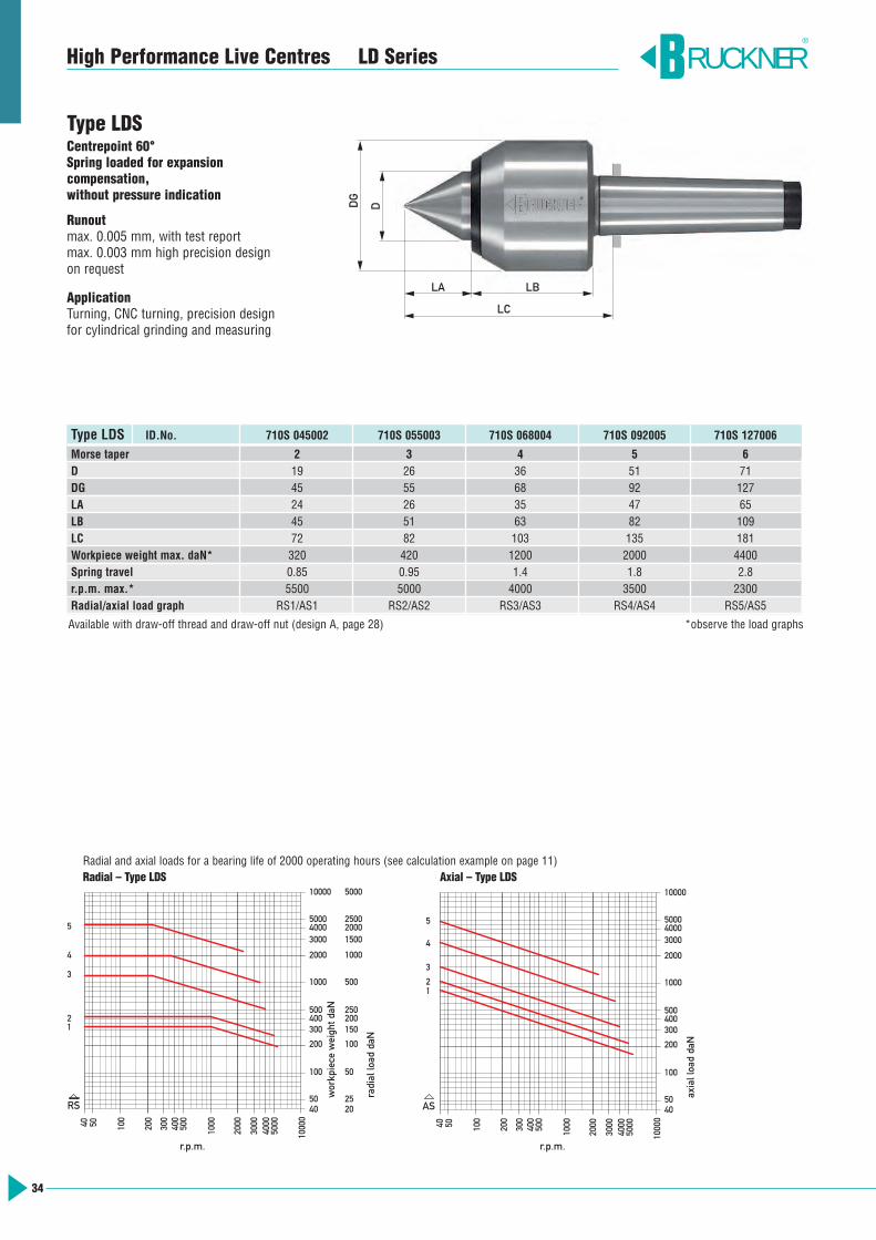
Type LDSCentrepoint 60° Spring loaded for expansion compensation,without pressure indication
Runoutmax. 0.005 mm, with test reportmax. 0.003 mm high precision design on request
ApplicationTurning, CNC turning, precision designfor cylindrical grinding and measuring
RUCKNER®
5040 100
200
300
5000400
500
1000
2000
3000
4000
1000
0
Drehzahl 1/min
4
3
21
10000
500040003000
2000
1000
500400300
200
100
5040
200
2025
100
50
150
250
500
1000
20001500
2500
5000
Rad
ialb
elas
tung
daN
Wer
kstü
ckge
wic
ht d
aN
5
RS
30040 50 100
200
500
400
1000
2000
4000
3000
5000
1000
0
1000
4050
100
200
300400500
3000
2000
50004000
10000
Axi
albe
last
ung
daN
Drehzahl 1/min
4
3
21
5
AS
Radial and axial loads for a bearing life of 2000 operating hours (see calculation example on page 11)Radial – Type LDS Axial – Type LDS
LA
LC
LB
DG
D
Type LDS ID.No. 710S 045002 710S 055003 710S 068004 710S 092005 710S 127006
Morse taper 2 3 4 5 6D 19 26 36 51 71DG 45 55 68 92 127LA 24 26 35 47 65LB 45 51 63 82 109LC 72 82 103 135 181Workpiece weight max. daN* 320 420 1200 2000 4400Spring travel 0.85 0.95 1.4 1.8 2.8r.p.m. max.* 5500 5000 4000 3500 2300Radial/axial load graph RS1/AS1 RS2/AS2 RS3/AS3 RS4/AS4 RS5/AS5
Available with draw-off thread and draw-off nut (design A, page 28) *observe the load graphs
r.p.m. r.p.m.
workpiece weight daN
radial load daN
axial load daN

35
High Performance Live Centres LD Series
Type LDACentre spindle with 1:5 external taper for interchangeable tapered caps.Spring loaded for expansion compensation,without pressure indication
Runoutmax. 0.005 mm, with test report
ApplicationWorkpieces with large bores.Retaining and extraction screws are included with these centres.
Basic body Tapered cap KAType LDA internal taper 1:5 ID.No. through hardened alloy tool steel
ID.No. D d K1 L
710A 045002 7KA2.056 56 15 18 44
710A 055003 7KA3.068 68 18 23 517KA3.110 110 60 23 53
710A 068004 7KA4.080 80 20 28 607KA4.130 130 70 28 62
710A 092005 7KA5.110 110 30 38 807KA5.175 175 95 38 80
710A 127006 7KA6.150 150 45 48 1017KA6.225 225 120 48 101
Type LDA ID.No. 710A 045002 710A 055003 710A 068004 710A 092005 710A 127006
Morse taper 2 3 4 5 6K1 18 23 28 38 48K2 14.3 18.4 22.3 30.4 37.6DG 45 55 68 92 127LA 22 26 31 42 58LB 45 51 63 82 109LC 70 82 99 129 173Workpiece weight max. daN* 280 320 900 1400 3600Spring travel 0.85 0.95 1.4 1.8 2.8r.p.m. max.* 5500 5000 4000 3500 2300Radial/axial load graph RA1/AA1 RA2/AA2 RA3/AA3 RA4/AA4 RA5/AA5
Available with draw-off thread and draw-off nut (design A, page 28) *observe the load graphs
RUCKNER®
5040 100
200
300
500040
050
0
1000
2000
3000
4000
1000
0
Drehzahl 1/min
10000
500040003000
2000
1000
500400300
200
100
5040
200
2025
100
50
150
250
500
1000
20001500
2500
5000
Rad
ialb
elas
tung
daN
Wer
kstü
ckge
wic
ht d
aN
4
3
21
5
RA
30040 50 100
200
500
400
1000
2000
4000
3000
5000
1000
0
1000
4050
100
200
300400500
3000
2000
50004000
10000
Axi
albe
last
ung
daN
Drehzahl 1/min
AA
4
3
21
5
Radial and axial loads for a bearing life of 2000 working hours (see calculation example page 11)Radial – Type LDA Axial – Type LDA
d DK1
60°
L
Special dimensions on request
LA
LC
LB
DG K1 K2
r.p.m. r.p.m.
workpiece weight daN
radial load daN
axial load daN
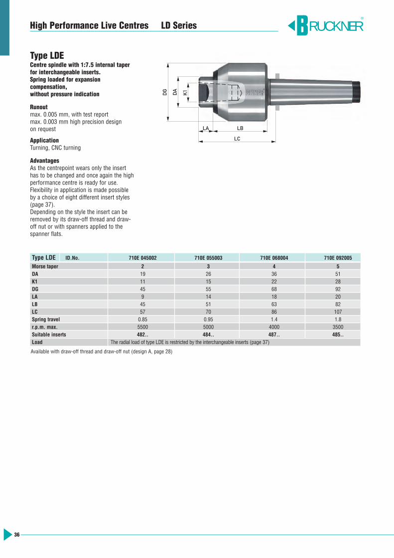
Type LDE ID.No. 710E 045002 710E 055003 710E 068004 710E 092005
Morse taper 2 3 4 5DA 19 26 36 51K1 11 15 22 28DG 45 55 68 92LA 9 14 18 20LB 45 51 63 82LC 57 70 86 107Spring travel 0.85 0.95 1.4 1.8r.p.m. max. 5500 5000 4000 3500Suitable inserts 482.. 484.. 487.. 485..Load The radial load of type LDE is restricted by the interchangeable inserts (page 37)
Available with draw-off thread and draw-off nut (design A, page 28)
RUCKNER®
36
High Performance Live Centres LD Series
LA
LC
LB
DG DA
K1
Type LDECentre spindle with 1:7.5 internal taper for interchangeable inserts.Spring loaded for expansion compensation,without pressure indication
Runoutmax. 0.005 mm, with test reportmax. 0.003 mm high precision design on request
ApplicationTurning, CNC turning
AdvantagesAs the centrepoint wears only the insert has to be changed and once again the high performance centre is ready for use.Flexibility in application is made possible by a choice of eight different insert styles(page 37).Depending on the style the insert can beremoved by its draw-off thread and draw-off nut or with spanners applied to thespanner flats.

RUCKNER®
37
High Performance Live Centres LD Series
Basic Centre Interchangeable Radial load Insert dimensions Thread Taper dimensions Types: LDE, TRE Inserts max. daN SW
taper 1:7.5
ID.No. ID.No. D d2 B d L LA K1 K2 l1
482AO 90 11.7 45 M 14x1.5482ASL 30 6 11.7 55 15 M 14x1.5482AKOP 90 5 11.7 50 M 14x1.5482A 90 17 45 SW14482B 90 11.7 4x2 45 M 14x1.5
11 8 23
482C 90 28 8x3 12 45 SW24482D 90 28 20x6 45 SW24482AOHM 60 7 11.7 45 M 14x1.5484AO 160 15.7 53 M 18x1.5484ASL 100 9 15.7 65 17 M 18x1.5484AKOP 160 6 15.7 58 M 18x1.5484A 160 25 60 SW22 15 11 30484B 110 15.7 4x2 53 M 18x1.5484C 160 44 15x5 24 60 SW41484D 160 44 35x12 64 SW41484AOHM 60 7 15.7 53 M 18x1.5487AO 300 21.6 74 M 24x1.5487ASL 100 9 21.6 86 17 M 24x1.5487AKOP 300 8 21.6 80 M 24x1.5487A 300 32 82 SW27 22 16.4 42487B 240 21.6 5x2,5 74 M 24x1.5487C 300 55 20x6 30 82 SW50487D 300 55 45x15 85 SW50487AOHM 200 11 21.6 74 M 24x1.5485AO 500 27.7 93 M 30x1.5485ASL 180 13 27.7 110 27 M 30x1.5485AKOP 500 8 27.7 105 M 30x1.5485A 500 45 105 SW41 28 21 52.5485B 500 27.7 7x3 93 M 30x1.5485C 500 65 25x6 35 105 SW55485D 500 65 55x20 105 SW55485AOHM 500 18 27.7 93 M 30x1.5
710E 045002
710E 055003
700E 055VDI30700E 055CO4700E 055Zyl25,4700E 055Zyl25700E 055Zyl32
710E 068004
700E 068VDI40700E 068CO5700E 068CO6700E 068Zyl32700E 068Zyl40
710E 092005
Installation pasteMakes insert change easier.Apply thinly and evenly to the insert taper.
ID.No. Content
P 10 100 g
Interchangeable insertstaper 1:7.5, in gauge accuracy
Form A0, 60°draw-off thread
Form ASL, 60°slim, extendeddraw-off thread
Form AK0P, 60°/40°extendeddraw-off thread
Form A, 60°for hollow partsspanner flat (SW)
Form B, centre 60°for centreless workpieces, draw-off thread
Form C, centre 60°for centreless workpieces, external angle 60° for hollowparts, spanner flat (SW)
Form D, centre 60°for centreless workpieces, spanner flat (SW)
Form A0HM, 60°with carbide insertdraw-off thread
D
D
Dd2
d2
K2K1
L
LA
L
L
l1
D
L
Bd2
L
L
BdD
B
Dd2
d2
L
L
38
Example of function for T Line
low clamping force medium clamping force high clamping force
Range of axial force per coloured ring
RUCKNER®
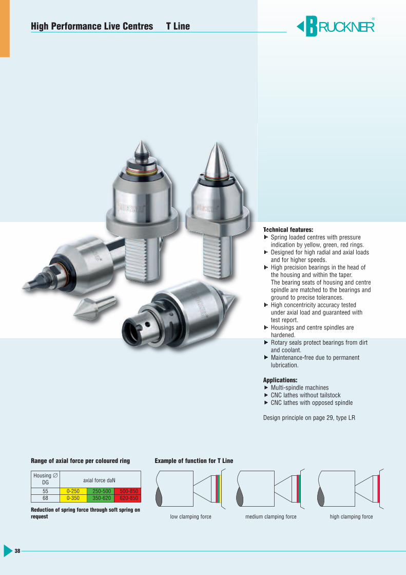
Technical features: Spring loaded centres with pressure
indication by yellow, green, red rings. Designed for high radial and axial loads
and for higher speeds. High precision bearings in the head of
the housing and within the taper. The bearing seats of housing and centrespindle are matched to the bearings andground to precise tolerances.
High concentricity accuracy testedunder axial load and guaranteed withtest report.
Housings and centre spindles are hardened.
Rotary seals protect bearings from dirt and coolant.
Maintenance-free due to permanent lubrication.
Applications: Multi-spindle machines CNC lathes without tailstock CNC lathes with opposed spindle
Design principle on page 29, type LR
High Performance Live Centres T Line
Housing ∅DG axial force daN
55 0-250 250-500 500-85068 0-350 350-620 620-850
Reduction of spring force through soft spring onrequest
DDA
39
High Performance Live Centres T Line
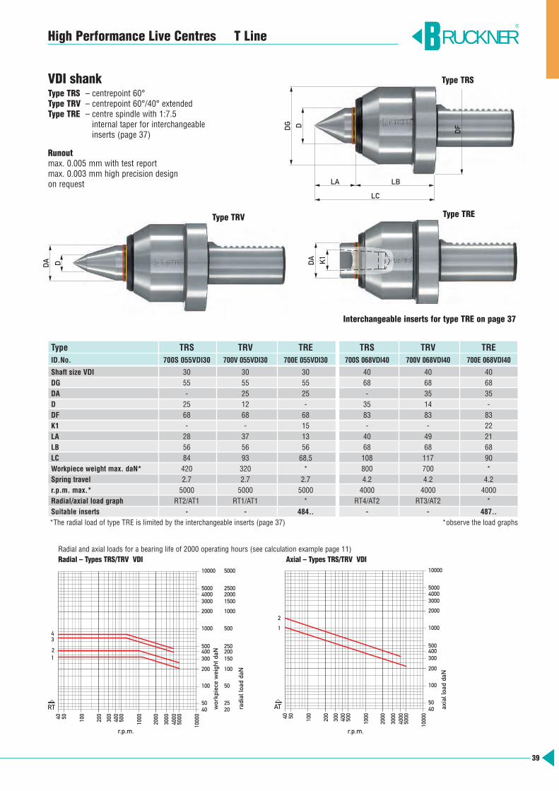
VDI shankType TRS – centrepoint 60° Type TRV – centrepoint 60°/40° extended Type TRE – centre spindle with 1:7.5
internal taper for interchangeableinserts (page 37)
Runoutmax. 0.005 mm with test reportmax. 0.003 mm high precision design on request
Type TRS TRV TRE TRS TRV TREID.No. 700S 055VDI30 700V 055VDI30 700E 055VDI30 700S 068VDI40 700V 068VDI40 700E 068VDI40
Shaft size VDI 30 30 30 40 40 40DG 55 55 55 68 68 68DA - 25 25 - 35 35D 25 12 - 35 14 -DF 68 68 68 83 83 83K1 - - 15 - - 22LA 28 37 13 40 49 21LB 56 56 56 68 68 68LC 84 93 68,5 108 117 90Workpiece weight max. daN* 420 320 * 800 700 *Spring travel 2.7 2.7 2.7 4.2 4.2 4.2r.p.m. max.* 5000 5000 5000 4000 4000 4000Radial/axial load graph RT2/AT1 RT1/AT1 * RT4/AT2 RT3/AT2 *Suitable inserts - - 484.. - - 487..*The radial load of type TRE is limited by the interchangeable inserts (page 37) *observe the load graphs
RUCKNER®
Type TRV
50
40
100
200
300
5000
400
500
1000
2000
3000
40
00
1000
0
Drehzahl 1/min
1
3
10000
5000 4000 3000
2000
1000
500 400 300
200
100
50 40
200
20 25
100
50
150
250
500
1000
2000 1500
2500
5000
Rad
ialb
elas
tung
daN
Wer
kstü
ckge
wic
ht d
aN2
4
RT
300 40
50
100
200
500
400
1000
2000
4000
30
00
5000
1000
0
1000
40 50
100
200
300 400 500
3000
2000
5000 4000
10000
Axi
albe
last
ung
daN
Drehzahl 1/min
AT
2
1
Radial and axial loads for a bearing life of 2000 operating hours (see calculation example page 11)Radial – Types TRS/TRV VDI Axial – Types TRS/TRV VDI
LA LB
DG D
LC
DF
Type TRS
Type TRE
K1
DA
Interchangeable inserts for type TRE on page 37
r.p.m. r.p.m.
workpiece weight daN
radial load daN
axial load daN
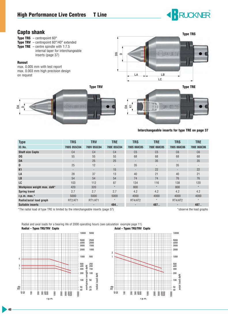
Capto shankType TRS – centrepoint 60° Type TRV – centrepoint 60°/40° extended Type TRE – centre spindle with 1:7.5
internal taper for interchangeableinserts (page 37)
Runoutmax. 0.005 mm with test reportmax. 0.003 mm high precision design on request
RUCKNER®
Type TRS TRV TRE TRS TRE TRS TREID.No. 700S 055C04 700V 055C04 700E 055C04 700S 068C05 700E 068C05 700S 068C06 700E 068C06
Shaft size Capto C4 C4 C4 C5 C5 C6 C6DG 55 55 55 68 68 68 68DA - 25 25 - 35 - 35D 25 12 - 35 - 35 -K1 - - 15 - 22 - 22LA 28 37 13 40 21 40 21LB 54 54 54 74 74 76 76LC 103 112 87 134 116 138 120Workpiece weight max. daN* 420 320 * 800 * 800 *Spring travel 2.7 2.7 2.7 4.2 4.2 4.2 4.2r.p.m. max.* 5000 5000 5000 4000 4000 4000 4000Radial/axial load graph RT2/AT1 RT1/AT1 * RT4/AT2 * RT4/AT2 *Suitable inserts - - 484.. - 487.. - 487..
40
High Performance Live Centres T Line50
40
100
200
300
5000
400
500
1000
2000
3000
40
00
1000
0
Drehzahl 1/min
1
10000
5000 4000 3000
2000
1000
500 400 300
200
100
50 40
200
20 25
100
50
150
250
500
1000
2000 1500
2500
5000
Rad
ialb
elas
tung
daN
Wer
kstü
ckge
wic
ht d
aN2
4
RT
300 40
50
100
200
500
400
1000
2000
4000
30
00
5000
1000
0
1000
40 50
100
200
300 400 500
3000
2000
5000 4000
10000
Axi
albe
last
ung
daN
Drehzahl 1/min
AT
2
1
Radial and axial loads for a bearing life of 2000 operating hours (see calculation example page 11)Radial – Types TRS/TRV Capto Axial – Types TRS/TRV Capto
LC
LA LB
DG D
DDA
Type TRS
Type TRV
K1
DA
Type TRE
Interchangeable inserts for type TRE on page 37
r.p.m. r.p.m.
workpiece weight daN
radial load daN
axial load daN
*The radial load of type TRE is limited by the interchangeable inserts (page 37) *observe the load graphs
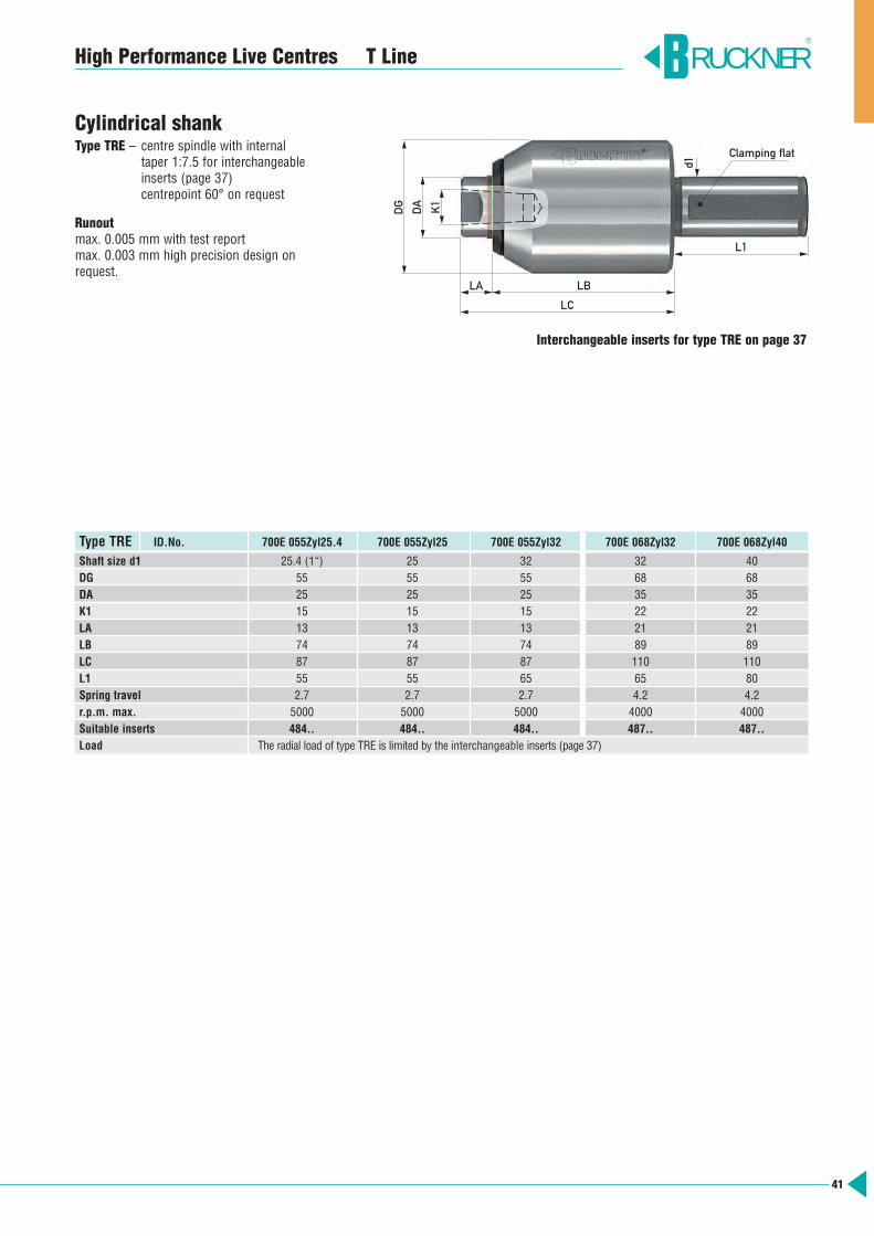
Cylindrical shankType TRE – centre spindle with internal
taper 1:7.5 for interchangeable inserts (page 37)centrepoint 60° on request
Runoutmax. 0.005 mm with test reportmax. 0.003 mm high precision design onrequest.
RUCKNER®
41
Type TRE ID.No. 700E 055Zyl25.4 700E 055Zyl25 700E 055Zyl32 700E 068Zyl32 700E 068Zyl40
Shaft size d1 25.4 (1“) 25 32 32 40DG 55 55 55 68 68DA 25 25 25 35 35K1 15 15 15 22 22LA 13 13 13 21 21LB 74 74 74 89 89LC 87 87 87 110 110L1 55 55 65 65 80Spring travel 2.7 2.7 2.7 4.2 4.2r.p.m. max. 5000 5000 5000 4000 4000Suitable inserts 484.. 484.. 484.. 487.. 487..Load The radial load of type TRE is limited by the interchangeable inserts (page 37)
High Performance Live Centres T Line
LB
L1
d1
Clamping flat
LA
LC
DG
DA K1
Interchangeable inserts for type TRE on page 37
42
Heavy workpieces – safe clamping, precision machiningThe live centre is an important element in a load system of a heavy-dutymachine tool and plays a decisive role in the final machining result. The BRUCKNER design is especially suited to the high requirements ofheavy-duty machining. The maximum admissible load depends on the mounting taper diameterand we therefore offer a choice of two different designs:Load carried only on the taperLoad carried on the taper with additional tailstock-sleeve support
The formula is applicable when the workpiece weight FW is equally dividedbetween headstock and tailstock. If thecomponent has an irregular shape, theweight has to be split up correspondingly.The radial cutting force FS has to be eithera positive or negative figure, dependingon the direction of rotation. Any unbalance of the workpiece has to be allowed for with the centrifugal force FF.
Load capacity of live centres for heavy-duty machiningThe data for workpiece weight and loadgiven in our tables and diagrams arebased on the dynamic state of the livecentre. Taper and centrepoint cross sections are designed for actual operatingcriteria and not for static conditions. Theload figures are calculated for the averagediameter of the 60° angle.
The radial load measured on the clampingdiameter of workpiece and centrepoint isrelevant. The load can be determined bythe following approximation formula:
FR = ± FS + FFFW2
FR – radial loadFW – workpiece weightFS – Radial cutting forcesFF – centrifugal force
RUCKNER®
1
2
3
4
▼▼
High Performance Live Centres for heavy-duty machining
High concentricity accuracy
Shaft seal ringprotects the bearings from dirt and coolant
Housinghigh quality material, forged, therefore uniform grain structure,tensile strength approx. 1000 N/mm2
Head and shank hardened
Large zero clearance precision roller bearings to absorb radial and axial forces. No bearings in the taper shank.Bearing seats in the housing and onthe centre spindle are precision ground to ultra fine tolerances. The bearings and their seats areselected for optimum fit.Maintenance-free due to permanent lubrication
Safety spigot (patented)acts as an additional safeguardwhen connecting the centre housingto the support ring
5
Housing
Safety spigot
Tailstock sleeve
Support ring
1 2
3
4
5

43
RUCKNER®
High Performance Live Centres for heavy-duty machining
BRUCKNER high performance livecentres for heavy duty machiningare used on lathes and cylindricalgrinding machines in the heavyindustry. Manufacturers of turbines, large engines, rollers,machined parts for the oil industryetc. focus on BRUCKNER high performance live centres due totheir reliability, safety and accuracy.
www.KISSsoft.AG
Load valuesThe load values given in our tables are calculated with the world wide acknowledged software KISSsoft. When used in keeping with currently valid standards DIN and ISO, this software guarantees a safe and reliableload calculation.
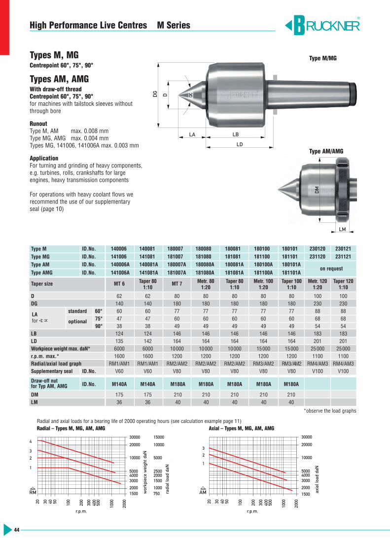
44
High Performance Live Centres M Series
Types M, MGCentrepoint 60°, 75°, 90°
Types AM, AMGWith draw-off threadCentrepoint 60°, 75°, 90°for machines with tailstock sleeves withoutthrough bore
RunoutType M, AM max. 0.008 mmType MG, AMG max. 0.004 mmTypes MG, 141006, 141006A max. 0.003 mm
ApplicationFor turning and grinding of heavy components,e.g. turbines, rolls, crankshafts for large engines, heavy transmission components
For operations with heavy coolant flows werecommend the use of our supplementary seal (page 10)
RUCKNER®
50
40
100
200
300
400
500
1000
2000
30000
20000
10000
5000 4000 3000
2000 1500
2000
1000 750
1500
2500
5000
10000
15000
Rad
ialb
elas
tung
daN
Wer
kstü
ckge
wic
ht d
aN
Drehzahl 1/min
30
20
4
3
2
1
RM
300 40
50
100
200
500
400
1000
2000
10000
1500
2000
3000 4000 5000
30000
20000
Axi
albe
last
ung
daN
Drehzahl 1/min
30
20
AM
1
3
2
Radial and axial loads for a bearing life of 2000 operating hours (see calculation example page 11)Radial – Types M, MG, AM, AMG Axial – Types M, MG, AM, AMG
Type M/MG
LM
DM
Type AM/AMG
LA
LD
LB
DG D ∝
r.p.m. r.p.m.
wor
kpie
ce w
eigh
t daN
radi
al lo
ad d
aN
axia
l loa
d da
N
Type M ID.No. 140006 140081 180007 180080 180081 180100 180101 230120 230121
Type MG ID.No. 141006 141081 181007 181080 181081 181100 181101 231120 231121
Type AM ID.No. 140006A 140081A 180007A 180080A 180081A 180100A 180101A
Type AMG ID.No. 141006A 141081A 181007A 181080A 181081A 181100A 181101A
Taper size MT 6 Taper 80 MT 7 Metr. 80 Taper 80 Metr. 100 Taper 100 Metr. 120 Taper 1201:10 1:20 1:10 1:20 1:10 1:20 1:10
D 62 62 80 80 80 80 80 100 100DG 140 140 180 180 180 180 180 230 230
standard 60° 60 60 77 77 77 77 77 88 8875° 47 47 60 60 60 60 60 68 6890° 38 38 49 49 49 49 49 54 54
LB 124 124 146 146 146 146 146 183 183LD 135 142 164 164 164 164 164 201 201Workpiece weight max. daN* 6000 6000 10000 10000 10000 15000 15000 25000 25000r.p.m. max.* 1600 1600 1200 1200 1200 1200 1200 1100 1100Radial/axial load graph RM1/AM1 RM1/AM1 RM2/AM2 RM2/AM2 RM2/AM2 RM3/AM2 RM3/AM2 RM4/AM3 RM4/AM3Supplementary seal ID.No. V60 V60 V80 V80 V80 V80 V80 V100 V100
*observe the load graphs
Draw-off nut for Typ AM, AMG ID.No. M140A M140A M180A M180A M180A M180A M180A
DM 175 175 210 210 210 210 210LM 36 36 40 40 40 40 40
optional
on request
LAfor a∝
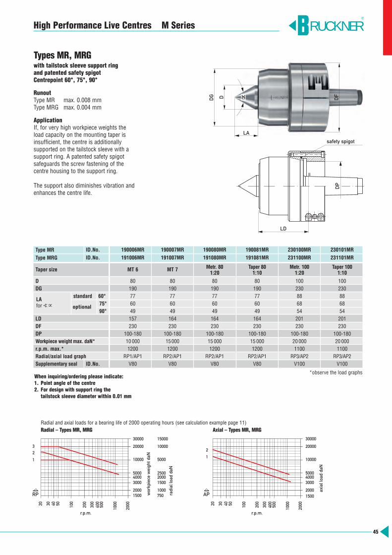
45
High Performance Live Centres M Series
Types MR, MRGwith tailstock sleeve support ring and patented safety spigotCentrepoint 60°, 75°, 90°
RunoutType MR max. 0.008 mmType MRG max. 0.004 mm
ApplicationIf, for very high workpiece weights theload capacity on the mounting taper isinsufficient, the centre is additionally supported on the tailstock sleeve with asupport ring. A patented safety spigot safeguards the screw fastening of the centre housing to the support ring.
The support also diminishes vibration andenhances the centre life.
Type MR ID.No. 190006MR 190007MR 190080MR 190081MR 230100MR 230101MR
Type MRG ID.No. 191006MR 191007MR 191080MR 191081MR 231100MR 231101MR
Taper size MT 6 MT 7 Metr. 80 Taper 80 Metr. 100 Taper 1001:20 1:10 1:20 1:10
D 80 80 80 80 100 100DG 190 190 190 190 230 230
standard 60° 77 77 77 77 88 8875° 60 60 60 60 68 6890° 49 49 49 49 54 54
LD 157 164 164 164 201 201DF 230 230 230 230 230 230DP 100-180 100-180 100-180 100-180 100-180 100-180Workpiece weight max. daN* 10000 15000 15000 15000 20000 20000r.p.m. max.* 1200 1200 1200 1200 1100 1100Radial/axial load graph RP1/AP1 RP2/AP1 RP2/AP1 RP2/AP1 RP3/AP2 RP3/AP2Supplementary seal ID.No. V80 V80 V80 V80 V100 V100
*observe the load graphs
RUCKNER®
optional
50
40
100
200
300
400
500
1000
2000
30000
20000
10000
5000 4000 3000
2000 1500
2000
1000 750
1500
2500
5000
10000
15000
Rad
ialb
elas
tung
daN
Wer
kstü
ckge
wic
ht d
aN
Drehzahl 1/min
30
20
32
1
RP
300 40
50
100
200
500
400
1000
2000
10000
1500 2000
3000 4000 5000
30000
20000
Axi
albe
last
ung
daN
Drehzahl 1/min
30
20
AP
2
1
Radial and axial loads for a bearing life of 2000 operating hours (see calculation example page 11)Radial – Types MR, MRG Axial – Types MR, MRG
LD
DP
DG DFD
LA
∝
When inquiring/ordering please indicate:1. Point angle of the centre2. For design with support ring the
tailstock sleeve diameter within 0.01 mm
safety spigot
LAfor a∝
r.p.m. r.p.m.
wor
kpie
ce w
eigh
t daN
radi
al lo
ad d
aN
axia
l loa
d da
N

DDG
LDLA
LB
∝
46
High Performance Live Centres M Series
Type MZwith expansion compensationand pressure indication by graduated dialCentrepoint 60°, 75°, 90°
Runoutmax. 0.008 mmmax. 0.004 mm on request
ApplicationIf the axial pressure must not exceed orfall below a defined value to clamp thecomponent safely or to avoid workpiecedeformation. When machining heavy workpieces proneto heat expansion.
Type MZ without draw-off thread
Type AMZ with draw-off threadfor machines with tailstock sleevewithout through bore (draw-off nut page 44)
Type MZR with tailstock sleeve support ring and patented safety spigot(page 42)The tailstock sleeve support:makes the connection between tailstocksleeve and centre housing sturdier
minimises the possibility of machining vibrations
We recommend our tailstock sleeve support design whenmachining heavy workpieces, unbalanced and/or interrupted cuts
high quality workpiece surface finishesare required
Adjusting the clamping pressureThe tailstock pressure required is adjustedon the graduated dial. When clamping thecomponent, the central measuring pin islifted in proportion to the travel of thecentre spindle.The required clamping force is reachedwhen measuring pin and scaling ring surface are level.
Pressure too low Correct pressure Pressure too high
RUCKNER®
Type MZ
Type AMZ
Type MZR
DP
DF
LD
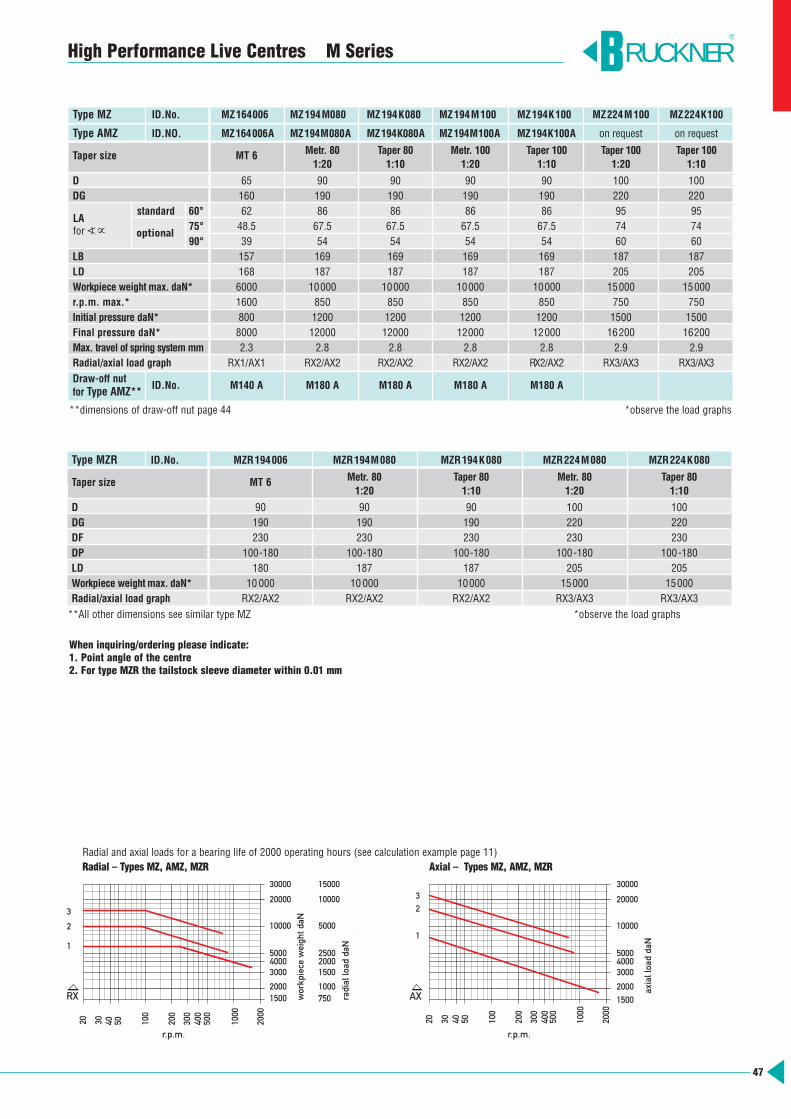
47
High Performance Live Centres M Series
Type MZ ID.No. MZ164006 MZ194M080 MZ194K080 MZ194M100 MZ194K100 MZ224M100 MZ224K100
Type AMZ ID.NO. MZ164006A MZ194M080A MZ194K080A MZ194M100A MZ194K100A on request on request
Taper size MT 6 Metr. 80 Taper 80 Metr. 100 Taper 100 Taper 100 Taper 1001:20 1:10 1:20 1:10 1:20 1:10
D 65 90 90 90 90 100 100DG 160 190 190 190 190 220 220
standard 60° 62 86 86 86 86 95 9575° 48.5 67.5 67.5 67.5 67.5 74 7490° 39 54 54 54 54 60 60
LB 157 169 169 169 169 187 187LD 168 187 187 187 187 205 205Workpiece weight max. daN* 6000 10000 10000 10000 10000 15000 15000r.p.m. max.* 1600 850 850 850 850 750 750Initial pressure daN* 800 1200 1200 1200 1200 1500 1500Final pressure daN* 8000 12000 12000 12000 12000 16200 16200Max. travel of spring system mm 2.3 2.8 2.8 2.8 2.8 2.9 2.9Radial/axial load graph RX1/AX1 RX2/AX2 RX2/AX2 RX2/AX2 RX2/AX2 RX3/AX3 RX3/AX3Draw-off nutfor Type AMZ** ID.No. M140 A M180 A M180 A M180 A M180 A
Type MZR ID.No. MZR194006 MZR194M080 MZR194K080 MZR224M080 MZR224K080
Taper size MT 6 Metr. 80 Taper 80 Metr. 80 Taper 801:20 1:10 1:20 1:10
D 90 90 90 100 100DG 190 190 190 220 220DF 230 230 230 230 230DP 100-180 100-180 100-180 100-180 100-180LD 180 187 187 205 205Workpiece weight max. daN* 10000 10000 10000 15000 15000Radial/axial load graph RX2/AX2 RX2/AX2 RX2/AX2 RX3/AX3 RX3/AX3**All other dimensions see similar type MZ *observe the load graphs
RUCKNER®
50
40
100
200
300
400
500
1000
2000
Drehzahl 1/min
30
20
30000
20000
10000
5000 4000 3000
2000 1500
2000
1000 750
1500
2500
5000
10000
15000
Rad
ialb
elas
tung
daN
Wer
kstü
ckge
wic
ht d
aN
3
2
1
RX
300
40
50
100
200
500
400
1000
2000
10000
1500
2000
3000 4000 5000
30000
20000
Axi
albe
last
ung
daN
Drehzahl 1/min
30
20
AX
1
3 2
Radial and axial loads for a bearing life of 2000 operating hours (see calculation example page 11)Radial – Types MZ, AMZ, MZR Axial – Types MZ, AMZ, MZR
optional
**dimensions of draw-off nut page 44 *observe the load graphs
When inquiring/ordering please indicate:1. Point angle of the centre2. For type MZR the tailstock sleeve diameter within 0.01 mm
LAfor a∝
r.p.m. r.p.m.
wor
kpie
ce w
eigh
t daN
radi
al lo
ad d
aN
axia
l loa
d da
N

48
Bullnose centre head and taper shankThe bullnose centre head is of wear-resistant, through-hardened alloy toolsteel. In contrast to usual case-hardening,this allows the head of the centre to bereground several times without any loss ofhardness. The taper shank is case hardened for protection from damage.
Tolerance of taper shankThe Morse taper is ground according toDIN 228 AT4 (gauge accuracy). This finetolerance guarantees a close fit of the high performance bullnose centre in thetailstock and the full utilisation of the concentricity accuracy.
Load valuesThe load values given in our tables are calculated with the world wide acknowledgedsoftware KISSsoft. When used in keeping with currently valid standards DIN andISO, this software guarantees a safe and reliable load calculation.
Precision bearingsThe bearings are selected according to thesize of the Morse taper.The bearing seatsof the head and the taper shank are matched to the bearings and ground toprecise tolerances. Bearings and theirseats are selected to fit.Result: high stability, minimum runoutand long life.
MaintenanceThe bearings are maintenance free due topermanent lubrication.
Repair serviceOur repair service is at your disposal. We judge the tool’s condition and informyou about the extent of necessary refurbishment.
BRUCKNER WORKS STANDARDOur high performance bullnose live centres – standard as well as specialdesigns – are produced and tested according to our own stringent worksstandard. Materials, production andtesting are subject to strict quality guidelines guaranteeing function and performance of our tools.
Test report for concentricity accuracyEvery single BRUCKNER high performancebullnose live centre is tested for its run-out under axial load. The test result is then stamped into the centre and is guaranteed by the test report and qualityguidelines guaranteeing function.
Example: table „maximum runout“ for types ZA, ZAG
RUCKNER®
TypeZA TypeZAG Morse taper Runout max. FaxType ZA Type ZAG daN
1920-1922 2120-2122 2 0.007 0.003 1601930 2130 3 0.007 0.003 160
1831-1933 2031-2133 3 0.007 0.003 2101841-1941 2041-2141 4 0.007 0.003 2101942-1947 2142-2147 4 0.007 0.003 450
1952 2152 5 0.007 0.003 4501953 2153 5 0.007 0.003 600
1954-1959 2154-2159 5 0.007 0.003 6001964-1970 2164-2170 6 0.007 0.003 6001983-1985 2183-2185 6 0.007 0.003 600
High Performance Bullnose Live Centres BRUCKNER WORKS STANDARD
www.KISSsoft.AG
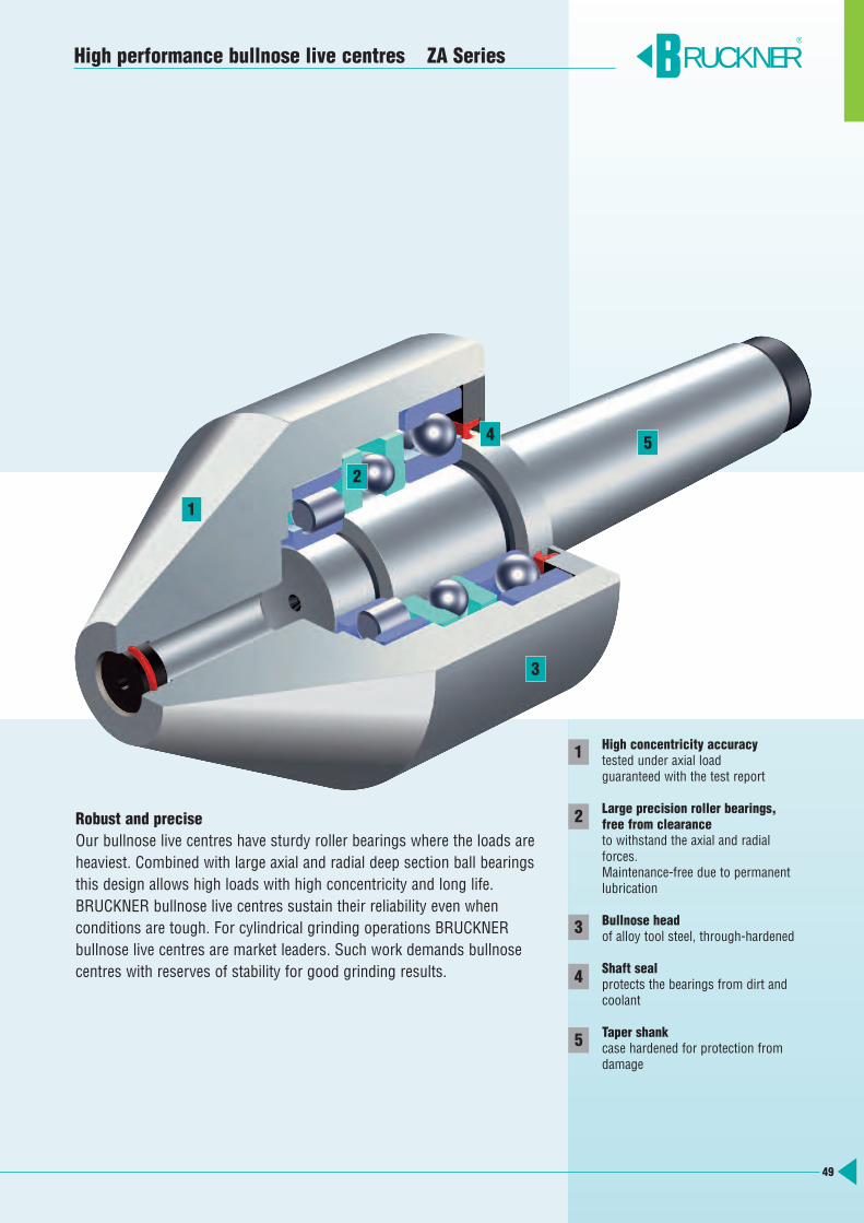
49
Robust and precise Our bullnose live centres have sturdy roller bearings where the loads areheaviest. Combined with large axial and radial deep section ball bearingsthis design allows high loads with high concentricity and long life. BRUCKNER bullnose live centres sustain their reliability even when conditions are tough. For cylindrical grinding operations BRUCKNER bullnose live centres are market leaders. Such work demands bullnosecentres with reserves of stability for good grinding results.
RUCKNER®
1
2
3
4
5
High performance bullnose live centres ZA Series
High concentricity accuracytested under axial loadguaranteed with the test report
Large precision roller bearings, free from clearanceto withstand the axial and radial forces.Maintenance-free due to permanent lubrication
Bullnose headof alloy tool steel, through-hardened
Shaft sealprotects the bearings from dirt andcoolant
Taper shankcase hardened for protection fromdamage
3
5
1
2
4

50
Types ZA, ZAGAngle 60°, 75°without draw-off thread
RunoutType ZA max. 0.007 mmType ZAG max. 0.003 mmwith test report
ApplicationFor turning and grinding tubesand workpieces with large bores
Mechanical engineeringMain spindles for machine tools,hollow shafts, paper rolls, ringsand gears
Car industry/Motor constructionTruck axial tubes, pistons,cylinder liners, crankshafts, wheel hubs
Aircraft industry/ShipbuildingEngine main shafts and transmission components, turbines, drive shafts
RUCKNER®
5040 100
200
300
5000400
500
1000
2000
3000
4000
1000
0
Drehzahl 1/min
10000
500040003000
2000
1000
500400300
200
100
5040
200
2025
100
50
150
250
500
1000
20001500
2500
5000
Rad
ialb
elas
tung
daN
Wer
kstü
ckge
wic
ht d
aN
3
2
1
RO
56
4
7
30040 50 100
200
500
400
1000
2000
4000
3000
5000
1000
0
1000
4050
100
200
300400500
3000
2000
50004000
10000
Axi
albe
last
ung
daN
Drehzahl 1/min
AO
4
21
3
5
Radial and axial loads for a bearing life of 2000 operating hours (see calculation example page 11)Radial – Types ZA, ZAG without draw-off-thread Axial – Types ZA, ZAG without draw-off-thread
dLB
LC
D
D
LB
LC
High Performance Bullnose Live Centres ZA Series
r.p.m. r.p.m.
wor
kpie
ce w
eigh
t daN
radi
al lo
ad d
aN
axia
l loa
d da
N

2 1920:60 2120:60 45 15 78 702 1821:60 2021:60 60 1 93 852 1921:60 2121:60 60 20 74 662 1922:60 2122:60 80 25 70 623 1930:60 2130:60 45 15 78 703 1831:60 2031:60 60 1 111 1043 1931:60 2131:60 60 20 95 883 1932:60 2132:60 80 25 95 883 1933:60 2133:60 100 35 95 884 1841:60 2041:60 60 1 113 1044 1941:60 2141:60 60 20 97 884 1942:60 2142:60 80 25 113 1004 1943:60 2143:60 100 35 113 1004 1944:60 2144:60 125 40 113 1004 1945:60 2145:60 150 50 113 1004 1947:60 2147:60 200 75 135 1225 1952:60 2152:60 80 25 113 1005 1953:60 2153:60 100 35 113 1005 1954:60 2154:60 125 40 144 1305 1955:60 2155:60 150 50 136 1225 1957:60 2157:60 200 75 136 1225 1958:60 2158:60 250 130 136 1225 1959:60 2159:60 300 180 136 1226 1964:60 2164:60 125 40 146 1306 1965:60 2165:60 150 50 138 1226 1967:60 2167:60 200 75 138 1226 1968:60 2168:60 250 130 138 1226 1969:60 2169:60 300 180 138 1226 1970:60 2170:60 350 230 138 1226 1983:60 2183:60 250 100 176 1606 1985:60 2185:60 350 180 186 170
51
High Performance Bullnose Live Centres ZA Series
Types ZA, ZAG 60° without draw-off thread
Bullnose centres with other shanks on request *observe the load graphs
RUCKNER®
Morsetaper
ID.No.
ZA ZAG
Load graph
radial axialD d LC LB
Workpieceweight
max. daN*
r.p.m.max.*
230 5000 RO1 AO1
450 4300 RO2 AO2
1200 3600 RO4 AO3
800 3600 RO3 AO3
1200 3600 RO4 AO3
2500 2000 RO5 AO4
3000 2000 RO6 AO4
6000 1500 RO7 AO5
5 1953:75 2153:75 100 25 109 965 1954:75 2154:75 125 30 144 1305 1955:75 2155:75 150 50 134 1205 1957:75 2157:75 200 75 124 1105 1958:75 2158:75 250 110 124 1105 1959:75 2159:75 300 160 124 1106 1964:75 2164:75 125 30 146 1306 1965:75 2165:75 150 50 136 1206 1967:75 2167:75 200 75 126 1106 1968:75 2168:75 250 110 126 1106 1969:75 2169:75 300 160 126 1106 1970:75 2170:75 350 190 138 1226 1983:75 2183:75 250 75 181 1656 1985:75 2185:75 350 120 186 170
Types ZA, ZAG 75° without draw-off thread
Bullnose centres with other shanks on request *observe the load graphs
Morsetaper
ID.No.
ZA ZAG
Load graph
radial axialD d LC LB
Workpieceweight
max. daN*
r.p.m.max.*
1200 3600 RO4 AO3
2500 2000 RO5 AO4
3000 2000 RO6 AO4
6000 1500 RO7 AO5
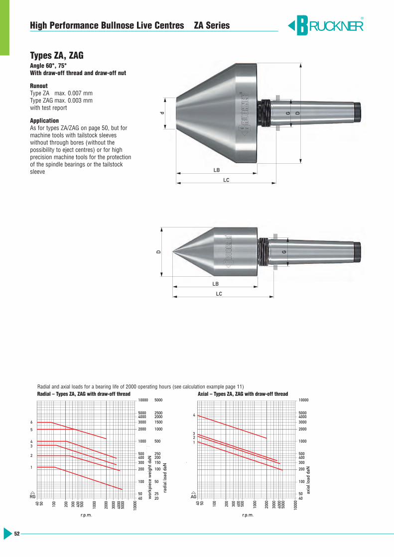
52
Types ZA, ZAGAngle 60°, 75°With draw-off thread and draw-off nut
RunoutType ZA max. 0.007 mmType ZAG max. 0.003 mmwith test report
ApplicationAs for types ZA/ZAG on page 50, but for machine tools with tailstock sleeveswithout through bores (without the possibility to eject centres) or for high precision machine tools for the protectionof the spindle bearings or the tailstocksleeve
RUCKNER®
5040 100
200
300
5000400
500
1000
2000
3000
4000
1000
0
Drehzahl 1/min
10000
500040003000
2000
1000
500400300
200
100
5040
200
2025
100
50
150
250
500
1000
20001500
2500
5000
Rad
ialb
elas
tung
daN
Wer
kstü
ckge
wic
ht d
aN
3
2
1
4
RG A
5
6
30040 50 100
200
500
400
1000
2000
4000
3000
5000
1000
0
1000
4050
100
200
300400500
3000
2000
50004000
10000
Axi
albe
last
ung
daN
Drehzahl 1/min
g
AG
4
21
3
Radial and axial loads for a bearing life of 2000 operating hours (see calculation example page 11)Radial – Types ZA, ZAG with draw-off thread Axial – Types ZA, ZAG with draw-off thread
d
LB
LC
G D
D
LB
LC
G
High Performance Bullnose Live Centres ZA Series
r.p.m. r.p.m.
wor
kpie
ce w
eigh
t daN
radi
al lo
ad d
aN
axia
l loa
d da
N

53
High Performance Bullnose Live Centres ZA Series RUCKNER®
2 1920:60A 2120:60A 45 15 86 70 M 22x1.52 1821:60A 2021:60A 60 1 101 85 M 22x1.52 1921:60A 2121:60A 60 20 82 66 M 22x1.52 1922:60A 2122:60A 80 25 78 62 M 22x1.53 1930:60A 2130:60A 45 15 86 70 M 28x1.53 1831:60A 2031:60A 60 1 120 104 M 28x1.53 1931:60A 2131:60A 60 20 104 88 M 28x1.53 1932:60A 2132:60A 80 25 104 88 M 28x1.53 1933:60A 2133:60A 100 35 104 88 M 28x1.54 1841:60A 2041:60A 60 1 120 104 M 35x1.54 1941:60A 2141:60A 60 20 104 88 M 35x1.54 1942:60A 2142:60A 80 25 119 100 M 35x1.54 1943:60A 2143:60A 100 35 119 100 M 35x1.54 1944:60A 2144:60A 125 40 119 100 M 35x1.54 1945:60A 2145:60A 150 50 119 100 M 35x1.54 1947:60A 2147:60A 200 75 141 122 M 35x1.55 1952:60A 2152:60A 80 25 129 100 M 48x1.55 1953:60A 2153:60A 100 35 129 100 M 48x1.55 1954:60A 2154:60A 125 40 158 130 M 50x1.55 1955:60A 2155:60A 150 50 150 122 M 50x1.55 1957:60A 2157:60A 200 75 150 122 M 50x1.55 1958:60A 2158:60A 250 130 150 122 M 50x1.55 1959:60A 2159:60A 300 180 150 122 M 50x1.56 1964:60A 2164:60A 125 40 159 130 M 68x1.56 1965:60A 2165:60A 150 50 151 122 M 68x1.56 1967:60A 2167:60A 200 75 151 122 M 68x1.56 1968:60A 2168:60A 250 130 151 122 M 68x1.56 1969:60A 2169:60A 300 180 151 122 M 68x1.56 1970:60A 2170:60A 350 230 151 122 M 68x1.5
Types ZA, ZAG 60° with draw-off thread and draw-off nut
Bullnose centres with other shanks on request *observe the load graphs
Morsetaper
ID.No.
ZA ZAG
Load graph
radial axialD d LC LB G
Workpieceweight
max. daN*
r.p.m.max.*
230 5000 RG1 AG1
450 4300 RG2 AG2
1000 3600 RG4 AG3
800 3600 RG3 AG3
1000 3600 RG4 AG3
2000 2000 RG5 AG4
3000 2000 RG6 AG4
5 1953:75A 2153:75A 100 25 125 96 M 48x1.55 1954:75A 2154:75A 125 30 158 130 M 50x1.55 1955:75A 2155:75A 150 50 148 120 M 50x1.55 1957:75A 2157:75A 200 75 138 110 M 50x1.55 1958:75A 2158:75A 250 110 138 110 M 50x1.55 1959:75A 2159:75A 300 160 138 110 M 50x1.56 1964:75A 2164:75A 125 30 159 130 M 68x1.56 1965:75A 2165:75A 150 50 149 120 M 68x1.56 1967:75A 2167:75A 200 75 139 110 M 68x1.56 1968:75A 2168:75A 250 110 139 110 M 68x1.56 1969:75A 2169:75A 300 160 139 110 M 68x1.56 1970:75A 2170:75A 350 190 151 122 M 68x1.5
Types ZA, ZAG 75° with draw-off thread and draw-off nut
Bullnose centres with other shanks on request *observe the load graphs
Morsetaper
ID.No.
ZA ZAG
Load graph
radial axialD d LC LB G
Workpieceweight
max. daN*
r.p.m.max.*
1000 3600 RG4 AG3
2000 2000 RG5 AG4
3000 2000 RG6 AG4
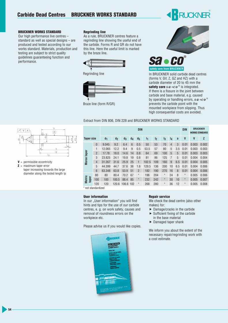
54
RUCKNER®
Carbide Dead Centres BRUCKNER WORKS STANDARD
BRUCKNER WORKS STANDARDOur high performance live centres – standard as well as special designs – areproduced and tested according to ourworks standard. Materials, production andtesting are subject to strict quality guidelines guaranteeing function and performance.
Regrinding lineAs a rule, BRUCKNER centres feature aregrinding line showing the useful end ofthe carbide. Forms R and GR do not havethis line. Here the useful limit is markedby the braze line.
In BRUCKNER solid carbide dead centres(forms V, GV, Z, GZ and HZ) with a carbide diameter of 20 to 45 mm thesafety core sa•co® is integrated. If there is a fissure in the joint betweencarbide and base material, e.g. caused by operating or handling errors, sa•co®
prevents the carbide point with the mounted workpiece from slipping. Thushigh consequential costs are avoided.
a co
®sRegrinding line
Braze line (form R/GR)
Extract from DIN 806, DIN 228 and BRUCKNER WORKS STANDARD
User informationIn our „User information“ you will findhints and tips for the use of our carbide centres, e. g. on work safety, causes andremoval of roundness errors on the workpiece etc.
Please advise us if you would like copies.
Repair serviceWe check the dead centre (also othermakes) for: Damage/cracks in the carbide Sufficient fixing of the carbidein the base material
Damaged taper shank
We inform you about the extent of thenecessary repair/regrinding work with a cost estimate.
V = permissible eccentricityZ = maximum taper error
taper increasing towards the largediameter along the tested length Ip
DIN DIN BRUCKNER
WORKS STANDARD
Taper size d1 d2 d3 d4 d5 l1 l2 l3 l4 a V V Z
0 9.045 9.2 6.4 6 0.5 50 53 70 4 3 0.01 0.003 0.0021 12.065 12.2 9.4 9 0.5 53.5 57 80 5 3.5 0.01 0.003 0.0032 17.78 18.0 14.6 14 0.8 64 69 100 5 5 0.01 0.003 0.0033 23.825 24.1 19.8 19 0.8 81 86 125 7 5 0.01 0.004 0.0044 31.267 31.6 25.9 25 1 102.5 109 160 9 6.5 0.01 0.004 0.0055 44.399 44.7 37.6 36 1.6 129.5 136 200 10 6.5 0.01 0.004 0.0066 63.348 63.8 53.9 51 2 182 190 270 16 8 0.01 0.004 0.00680 80 80.4 70.2 67 * 196 204 * 24 8 * 0.005 0.006100 100 100.5 88.4 85 * 232 242 * 30 10 * 0.005 0.007120 120 120.6 106.6 102 * 268 280 * 36 12 * 0.005 0.008
Morse ta
per
Metric
taper
*not standardized
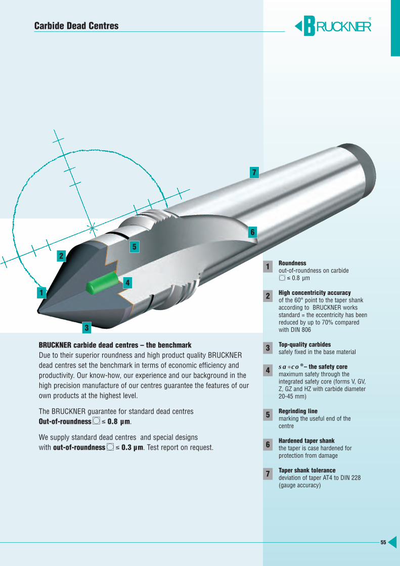
55
BRUCKNER carbide dead centres – the benchmarkDue to their superior roundness and high product quality BRUCKNERdead centres set the benchmark in terms of economic efficiency and productivity. Our know-how, our experience and our background in thehigh precision manufacture of our centres guarantee the features of ourown products at the highest level.
The BRUCKNER guarantee for standard dead centresOut-of-roundness ≤ 0.8 µm.
We supply standard dead centres and special designs with out-of-roundness ≤ 0.3 µm. Test report on request.
Roundnessout-of-roundness on carbide
≤ 0.8 µm
High concentricity accuracyof the 60° point to the taper shank according to BRUCKNER worksstandard = the eccentricity has beenreduced by up to 70% comparedwith DIN 806
Top-quality carbidessafely fixed in the base material
sa•co®– the safety coremaximum safety through the integrated safety core (forms V, GV,Z, GZ and HZ with carbide diameter20-45 mm)
Regrinding linemarking the useful end of thecentre
Hardened taper shankthe taper is case hardened for protection from damage
Taper shank tolerancedeviation of taper AT4 to DIN 228(gauge accuracy)
RUCKNER®
1
2
3
4
5
6
7
Carbide Dead Centres
3
5
1
2
4
6
7
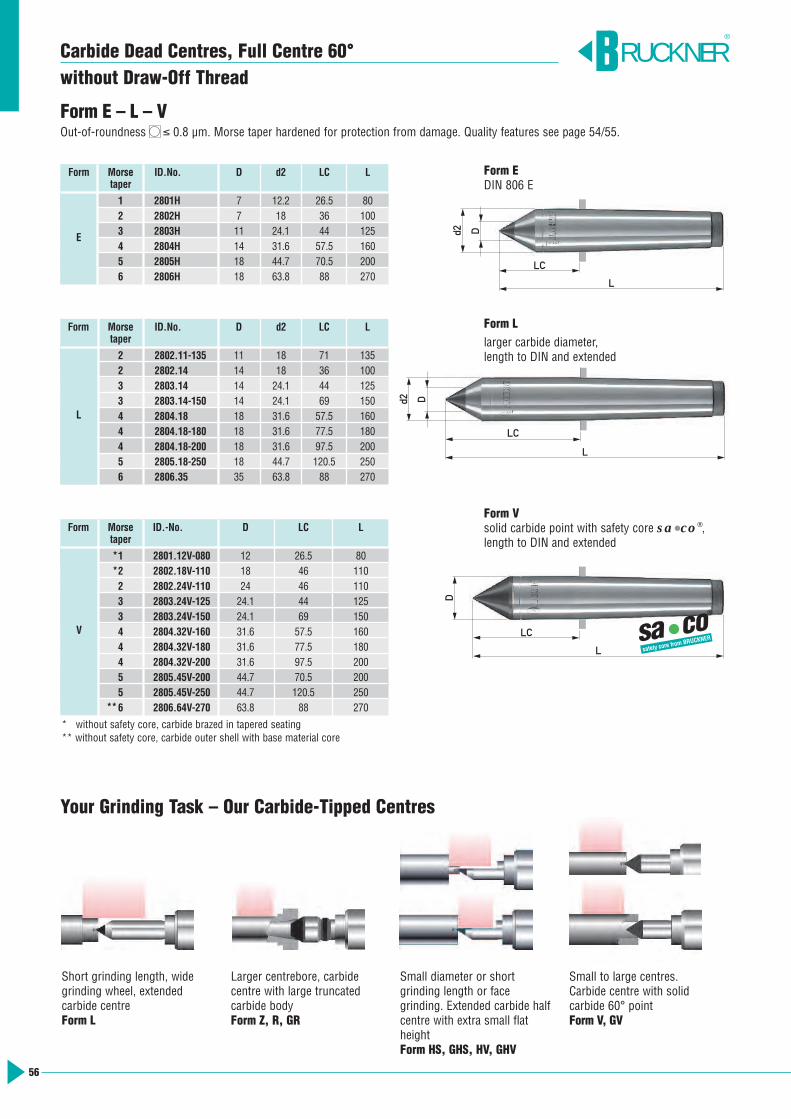
56
Form E – L – VOut-of-roundness ≤ 0.8 µm. Morse taper hardened for protection from damage. Quality features see page 54/55.
Form EDIN 806 E
Form Llarger carbide diameter, length to DIN and extended
Form Vsolid carbide point with safety core sa•co®,length to DIN and extended
Form Morse ID.No. D d2 LC Ltaper
1 2801H 7 12.2 26.5 802 2802H 7 18 36 1003 2803H 11 24.1 44 1254 2804H 14 31.6 57.5 1605 2805H 18 44.7 70.5 2006 2806H 18 63.8 88 270
Form Morse ID.No. D d2 LC Ltaper
2 2802.11-135 11 18 71 1352 2802.14 14 18 36 1003 2803.14 14 24.1 44 1253 2803.14-150 14 24.1 69 1504 2804.18 18 31.6 57.5 1604 2804.18-180 18 31.6 77.5 1804 2804.18-200 18 31.6 97.5 2005 2805.18-250 18 44.7 120.5 2506 2806.35 35 63.8 88 270
Form Morse ID.-No. D LC Ltaper
1 2801.12V-080 12 26.5 802 2802.18V-110 18 46 1102 2802.24V-110 24 46 1103 2803.24V-125 24.1 44 1253 2803.24V-150 24.1 69 1504 2804.32V-160 31.6 57.5 1604 2804.32V-180 31.6 77.5 1804 2804.32V-200 31.6 97.5 2005 2805.45V-200 44.7 70.5 2005 2805.45V-250 44.7 120.5 2506 2806.64V-270 63.8 88 270
L
E
V
RUCKNER®
*
**
*
* without safety core, carbide brazed in tapered seating** without safety core, carbide outer shell with base material core
Short grinding length, widegrinding wheel, extended carbide centreForm L
Larger centrebore, carbide centre with large truncated carbide bodyForm Z, R, GR
Small diameter or short grinding length or face grinding. Extended carbide halfcentre with extra small flatheightForm HS, GHS, HV, GHV
Small to large centres. Carbide centre with solid carbide 60° pointForm V, GV
Your Grinding Task – Our Carbide-Tipped Centres
LC
L
Dd2
LC
L
Dd2
LC
L
D
Carbide Dead Centres, Full Centre 60°without Draw-Off Thread
a co
®
s
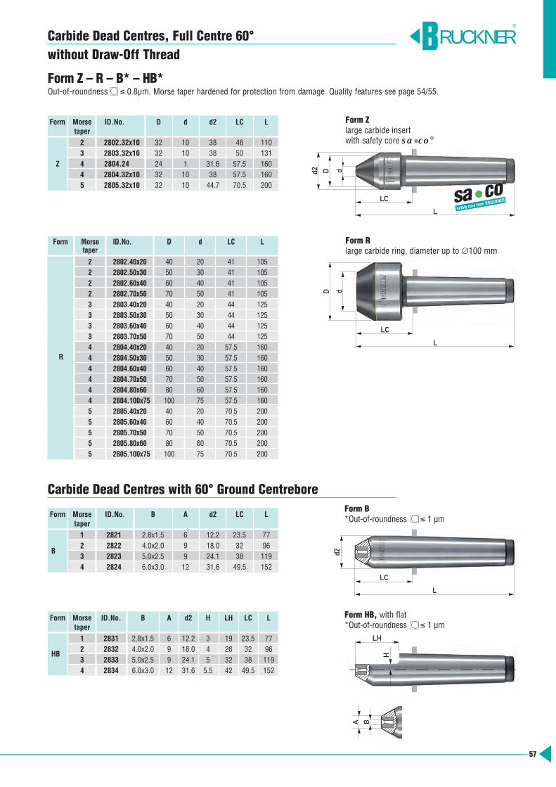
LC
L
d2
LC
L
d2 D d
Form Zlarge carbide insert with safety core sa•co®
57
Carbide Dead Centres, Full Centre 60° without Draw-Off Thread
Form Z – R – B* – HB*Out-of-roundness ≤ 0.8µm. Morse taper hardened for protection from damage. Quality features see page 54/55.
Form B*Out-of-roundness ≤ 1 µm
Form HB, with flat*Out-of-roundness ≤ 1 µm
Form Rlarge carbide ring, diameter up to ∅100 mm
Form Morse ID.No. D d LC Ltaper
2 2802.40x20 40 20 41 1052 2802.50x30 50 30 41 1052 2802.60x40 60 40 41 1052 2802.70x50 70 50 41 1053 2803.40x20 40 20 44 1253 2803.50x30 50 30 44 1253 2803.60x40 60 40 44 1253 2803.70x50 70 50 44 1254 2804.40x20 40 20 57.5 1604 2804.50x30 50 30 57.5 1604 2804.60x40 60 40 57.5 1604 2804.70x50 70 50 57.5 1604 2804.80x60 80 60 57.5 1604 2804.100x75 100 75 57.5 1605 2805.40x20 40 20 70.5 2005 2805.60x40 60 40 70.5 2005 2805.70x50 70 50 70.5 2005 2805.80x60 80 60 70.5 2005 2805.100x75 100 75 70.5 200
R
Form Morse ID.No. D d d2 LC Ltaper
2 2802.32x10 32 10 38 46 1103 2803.32x10 32 10 38 50 131
Z 4 2804.24 24 1 31.6 57.5 1604 2804.32x10 32 10 38 57.5 1605 2805.32x10 32 10 44.7 70.5 200
Form Morse ID.No. B A d2 LC Ltaper
1 2821 2.8x1.5 6 12.2 23.5 772 2822 4.0x2.0 9 18.0 32 963 2823 5.0x2.5 9 24.1 38 1194 2824 6.0x3.0 12 31.6 49.5 152
Form Morse ID.No. B A d2 H LH LC Ltaper
1 2831 2.8x1.5 6 12.2 3 19 23.5 772 2832 4.0x2.0 9 18.0 4 26 32 963 2833 5.0x2.5 9 24.1 5 32 38 1194 2834 6.0x3.0 12 31.6 5.5 42 49.5 152
RUCKNER®
D dLC
L
a co
®
s
LH
H
BA
Carbide Dead Centres with 60° Ground Centrebore
B
HB
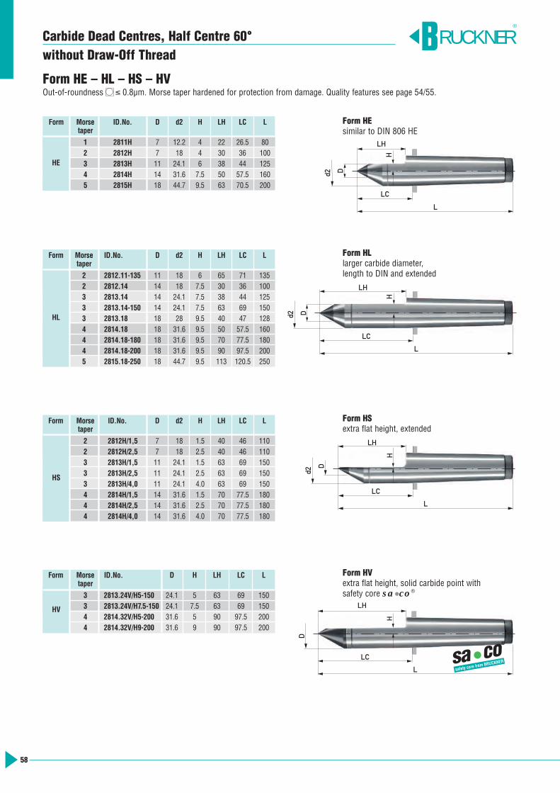
LH
LC
L
D
H
58
Carbide Dead Centres, Half Centre 60° without Draw-Off Thread
Form HE – HL – HS – HVOut-of-roundness ≤ 0.8µm. Morse taper hardened for protection from damage. Quality features see page 54/55.
Form HEsimilar to DIN 806 HE
Form HLlarger carbide diameter, length to DIN and extended
Form HSextra flat height, extended
Form HVextra flat height, solid carbide point withsafety core sa•co®
Form Morse ID.No. D d2 H LH LC Ltaper
1 2811H 7 12.2 4 22 26.5 802 2812H 7 18 4 30 36 1003 2813H 11 24.1 6 38 44 1254 2814H 14 31.6 7.5 50 57.5 1605 2815H 18 44.7 9.5 63 70.5 200
Form Morse ID.No. D d2 H LH LC Ltaper
2 2812.11-135 11 18 6 65 71 1352 2812.14 14 18 7.5 30 36 1003 2813.14 14 24.1 7.5 38 44 1253 2813.14-150 14 24.1 7.5 63 69 1503 2813.18 18 28 9.5 40 47 1284 2814.18 18 31.6 9.5 50 57.5 1604 2814.18-180 18 31.6 9.5 70 77.5 1804 2814.18-200 18 31.6 9.5 90 97.5 2005 2815.18-250 18 44.7 9.5 113 120.5 250
Form Morse ID.No. D d2 H LH LC Ltaper
2 2812H/1,5 7 18 1.5 40 46 1102 2812H/2,5 7 18 2.5 40 46 1103 2813H/1,5 11 24.1 1.5 63 69 1503 2813H/2,5 11 24.1 2.5 63 69 1503 2813H/4,0 11 24.1 4.0 63 69 1504 2814H/1,5 14 31.6 1.5 70 77.5 1804 2814H/2,5 14 31.6 2.5 70 77.5 1804 2814H/4,0 14 31.6 4.0 70 77.5 180
HE
HL
HS
Form Morse ID.No. D H LH LC Ltaper
3 2813.24V/H5-150 24.1 5 63 69 1503 2813.24V/H7.5-150 24.1 7.5 63 69 1504 2814.32V/H5-200 31.6 5 90 97.5 2004 2814.32V/H9-200 31.6 9 90 97.5 200
HV
RUCKNER®
a co
®
s
LH
LC
L
d2
D
H
LH
LC
L
d2 D
H
LH
LC
L
d2 D
H
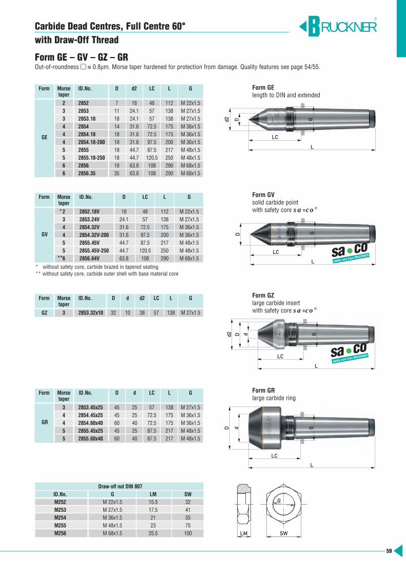
GDd2 d
LC
L
59
Carbide Dead Centres, Full Centre 60° with Draw-Off Thread
Form GE – GV – GZ – GROut-of-roundness ≤ 0.8µm. Morse taper hardened for protection from damage. Quality features see page 54/55.
Form GElength to DIN and extended
Form GVsolid carbide pointwith safety core sa•co®
Form GZlarge carbide insert with safety core sa•co®
Form GRlarge carbide ring
Form Morse ID.No. D d2 LC L Gtaper
2 2852 7 18 48 112 M 22x1.53 2853 11 24.1 57 138 M 27x1.53 2853.18 18 24.1 57 138 M 27x1.54 2854 14 31.6 72.5 175 M 36x1.54 2854.18 18 31.6 72.5 175 M 36x1.54 2854.18-200 18 31.6 97.5 200 M 36x1.55 2855 18 44.7 87.5 217 M 48x1.55 2855.18-250 18 44.7 120.5 250 M 48x1.56 2856 18 63.8 108 290 M 68x1.56 2856.35 35 63.8 108 290 M 68x1.5
Form Morse ID.No. D LC L Gtaper
2 2852.18V 18 48 112 M 22x1.53 2853.24V 24.1 57 138 M 27x1.54 2854.32V 31.6 72.5 175 M 36x1.54 2854.32V-200 31.6 97.5 200 M 36x1.55 2855.45V 44.7 87.5 217 M 48x1.55 2855.45V-250 44.7 120.5 250 M 48x1.56 2856.64V 63.8 108 290 M 68x1.5
Form Morse ID.No. D d d2 LC L Gtaper
3 2853.32x10 32 10 38 57 138 M 27x1.5
GV
GZ
GE
Form Morse ID.No. D d LC L Gtaper
3 2853.45x25 45 25 57 138 M 27x1.54 2854.45x25 45 25 72.5 175 M 36x1.54 2854.60x40 60 40 72.5 175 M 36x1.55 2855.45x25 45 25 87.5 217 M 48x1.55 2855.60x40 60 40 87.5 217 M 48x1.5
GR
LM SW
G
RUCKNER®
* without safety core, carbide brazed in tapered seating** without safety core, carbide outer shell with base material core
*
**
LC
L
D d GGd2 D
LC
L
a co
®
s
GD
LC
L a co
®
s
Draw-off nut DIN 807ID.No. G LM SWM252 M 22x1.5 15.5 32M253 M 27x1.5 17.5 41M254 M 36x1.5 21 55M255 M 48x1.5 23 75M256 M 68x1.5 25.5 100

60
Form Morse ID.No. D d2 H LH LC L Gtaper
3 2853/4.0-138 14 24.1 4.0 39.5 57.0 138 M 27x1.54 2854/4.0-175 14 31.6 4.0 51.5 72.5 175 M 36x1.54 2854/4.0-200 14 31.6 4.0 76.5 97.5 200 M 36x1.55 2855/6.0-217 18 44.7 6.0 64.5 87.5 217 M 48x1.55 2855/6.0-250 18 44.7 6.0 97.5 120.5 250 M 48x1.5
GHS
Form Morse ID.No. D H LH LC L Gtaper
3 2853.24V/H5-150 24.1 5 51.5 69 150 M 27x1.54 2854.32V/H5-200 31.6 5 76.5 97.5 200 M 36x1.54 2854.32V/H9-200 31.6 9 76.5 97.5 200 M 36x1.5
GHV
RUCKNER®
Form GHSextra flat height, length to DIN and extended
Form GHVextra flat height, solid carbide pointwith safety core sa•co®
LH
d2 D
LC
L
G
H
Carbide Dead Centres, Half Centre 60° with Draw-Off Thread
Form GHS – GHVOut-of-roundness ≤ 0.8µm. Morse taper hardened for protection from damage. Quality features see page 54/55.
„Roundness achieves roundness“ – Grinding test with standard centres from BRUCKNER
test conditions
cylindrical grinding machine STUDER S33
workpiece 100Cr6, 62 HRC, ∅ 35 mm, un-ground centre DIN 332A
BRUCKNER 2804H in the headstockOut-of-roundness 0.42 µm
BRUCKNER 2814H in the tailstockOut-of-roundness 0.48 µm
workpieceout-of-roundness 0.36 µm
Result:Out-of-roundness achieved with standard centres from BRUCKNER 0.36 µm.
D
LC
L
G
H
LH
a co
®
s
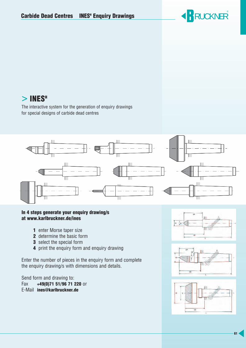
61
Carbide Dead Centres INESH Enquiry Drawings
INESH>The interactive system for the generation of enquiry drawings for special designs of carbide dead centres
In 4 steps generate your enquiry drawing/s at www.karlbruckner.de/ines
1 enter Morse taper size2 determine the basic form3 select the special form4 print the enquiry form and enquiry drawing
Enter the number of pieces in the enquiry form and completethe enquiry drawing/s with dimensions and details.
Send form and drawing to:Fax +49(0)71 51/96 71 220 orE-Mail [email protected]
RUCKNER®
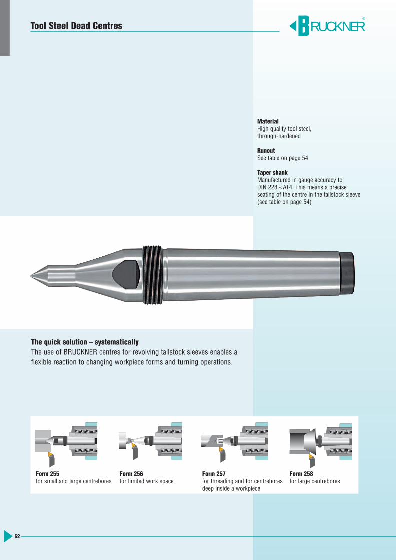
62
The quick solution – systematicallyThe use of BRUCKNER centres for revolving tailstock sleeves enables aflexible reaction to changing workpiece forms and turning operations.
MaterialHigh quality tool steel,through-hardened
RunoutSee table on page 54
Taper shankManufactured in gauge accuracy to DIN 228 ≤AT4. This means a precise seating of the centre in the tailstock sleeve(see table on page 54)
Form 255for small and large centrebores
Form 256for limited work space
Form 257for threading and for centreboresdeep inside a workpiece
Form 258for large centrebores
RUCKNER®
Tool Steel Dead Centres

63
Form 255 – 256 – 257 – 258Interchangeable dead centres, through-hardened for revolving tailstock sleeves
Form 256copying centre 60°/40°
Form 257slim design 60°/30°
Form Taper ID.No. D G SW LC L Draw-offsize nut
MT 2 2552 18 M 22x1.5 16 48 112 M2522553 24.1 M 27x1.5 22 57 138 M253
MT 3 2553-150 24.1 M 27x1.5 22 69 150 M2532553-170 24.1 M 27x1.5 22 89 170 M2532554 31.6 M 36x1.5 27 72.5 175 M254
MT 4 2554-190 31.6 M 36x1.5 27 87.5 190 M2542554-230 31.6 M 36x1.5 27 127.5 230 M254
MT 52555 44.7 M 48x1.5 41 87.5 217 M2552555-250 44.7 M 48x1.5 41 120.5 250 M255
MT 6 2556 63.8 M 68x1.5 55 108 290 M256Metr. 801:20 2557.20 80 M 85x2 – 134 330 M257
Taper 80 2557.10 80 M 85x2 – 130 330 M2571:10
255
Form Taper ID.No. D d2 G SW LC L Draw-offsize nut
MT 2 2562 6 18 M 22x1.5 16 48 112 M252MT 3 2563 8 24.1 M 27x1.5 22 57 138 M253MT 4 2564 10 31.6 M 36x1.5 27 72.5 175 M254MT 5 2565 12 44.7 M 48x1.5 41 87.5 217 M255MT 6 2566 15 63.8 M 68x1.5 55 136 318 M256
256
Form Taper ID.No. D d2 G SW LA LC L Draw-offsize nut
2572.06-120 6 18 M 22x1.5 16 15 56 120 M252MT 2 2572.09-120 9 18 M 22x1.5 16 17 56 120 M252
2572.11-120 11 18 M 22x1.5 16 21 56 120 M252
MT 32573.09-150 9 24.1 M 27x1.5 19 17 69 150 M2532573.13-150 13 24.1 M 27x1.5 19 25 69 150 M2532574.09-190 9 31.6 M 36x1.5 27 17 87.5 190 M254
MT 4 2574.13-190 13 31.6 M 36x1.5 27 27 87.5 190 M2542574.19-190 19 31.6 M 36x1.5 27 53 87.5 190 M254
257
Tool Steel Dead Centres with Draw-Off Thread Morse taper, metr. 80 1:20, taper 80 1:10
LM SW
G
RUCKNER®
Form Taper ID.No. D d G SW LC L Draw-offsize nut
MT 22582.40 40 1 M 22x1.5 36 64 128 M2522582.80x20 80 20 M 22x1.5 36 88 152 M252
MT 3 2583.40 40 1 M 27x1.5 36 65 146 M2532583. 2583.80x20 80 20 M 27x1.5 36 89 170 M253
MT 42584.80x20 80 20 M 36x1.5 36 89.5 192 M2542584.125x65 125 65 M 36x1.5 36 89.5 192 M2542585.80x20 80 20 M 48x1.5 50 100.5 230 M255
MT 5 2585.100x50 100 50 M 48x1.5 50 90.5 220 M2552585.125x65 125 65 M 48x1.5 50 100.5 230 M255
258
Form 258bullnose dead centre 60°
Draw-off nut to DIN 807ID.No. G LM SWM252 M 22x1.5 15.5 32M253 M 27x1.5 17.5 41M254 M 36x1.5 21 55M255 M 48x1.5 23 75M256 M 68x1.5 25.5 100M257 M 85x2.0 40 130
D Gd
L
LC
d2 D
LC
LA
L
G
d2 D
L
LC
G
D
L
LC
G
Form 255similar to DIN 807 and extended
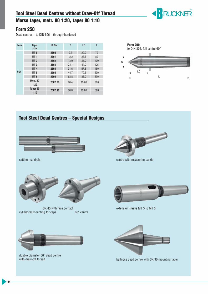
64
Tool Steel Dead Centres without Draw-Off ThreadMorse taper, metr. 80 1:20, taper 80 1:10
Form 250Dead centres – to DIN 806 – through-hardened
Tool Steel Dead Centres – Special Designs
Form Taper ID.No. D LC Lsize
MT 0 2500 9.2 20.0 70MT 1 2501 12.2 26.5 80MT 2 2502 18.0 36.0 100MT 3 2503 24.1 44.0 125MT 4 2504 31.6 57.5 160MT 5 2505 44.7 70.5 200MT 6 2506 63.8 88.0 270
Metr. 801:20
Taper 801:10
250
setting mandrels
SK 45 with face contactcylindrical mounting for caps 60° centre
centre with measuring bands
extension sleeve MT 5 to MT 5
RUCKNER®
D
L
LC
Form 250to DIN 806, full centre 60°
double diameter 60° dead centre with draw-off thread bullnose dead centre with SK 30 mounting taper
2507.20 80.4 124.0 320
2507.10 80.8 120.0 320
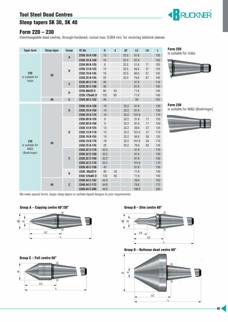
2330.10 A-130 10 32.2 61.6 130A 2330.10 A-150 10 32.2 81.6 150
2330.10 A-170 10 32.2 101.6 1702330.09 B-120 9 32.2 51.6 17 1202330.09 B-150 9 32.2 81.6 17 1502330.13 B-125 13 32.2 56.6 27 125
B 2330.13 B-170 13 32.2 101.6 27 1702330.19 B-135 19 32.2 66.6 50 135
302330.19 B-170 19 32.2 101.6 50 1702330.25 B-145 25 32.2 76.6 63 1452330.32 C-116 32.2 47.6 1162330.32 C-130 32.2 61.6 130
C 2330.32 C-150 32.2 81.6 1502330.32 C-170 32.2 101.6 1702330.45 C-130 45 61.6 130
D2330. 80x20 D 80 20 71.6 1402330.125x65 D 125 65 71.6 1402340.44 C-152 44.9 58.6 152
40 C 2340.44 C-172 44.9 78.6 1722340.44 C-200 44.9 106.6 200
230is suitable for
MAG (Boehringer)
65
Tool Steel Dead Centres Steep tapers SK 30, SK 40
Group A – Copying centre 60°/30°
Group C – Full centre 60°
Taper form Steep taper Group ID.No. D d d2 LC LA L
A2230.10 A-130 10 32.5 61.6 130
2230.10 A-150 10 32.5 81.6 1502230.09 B-120 9 32.5 51.6 17 120
B2230.13 B-125 13 32.5 56.6 27 125
302230.19 B-135 19 32.5 66.6 57 1352230.25 B-145 25 32.5 76.6 67 145
C2230.36 C-116 36 47.6 1162230.36 C-130 36 61.6 130
D2230.80x20 D 80 20 71.6 1402230.125x65 D 125 65 71.6 140
40 C 2240.48 C-152 48 59 152
220is suitable for
Index
Form 230is suitable for MAG (Boehringer)
Form 220 – 230Interchangeable dead centres, through-hardened, runout max. 0.004 mm, for revolving tailstock sleeves
RUCKNER®
We make special forms, larger steep tapers or carbide-tipped designs to your requirements.
Dd2
L
LC
D
L
LC
dD
L
LC
Group B – Slim centre 60°
Group D – Bullnose dead centre 60°
Form 220is suitable for Index
Dd2
L
LC
LA
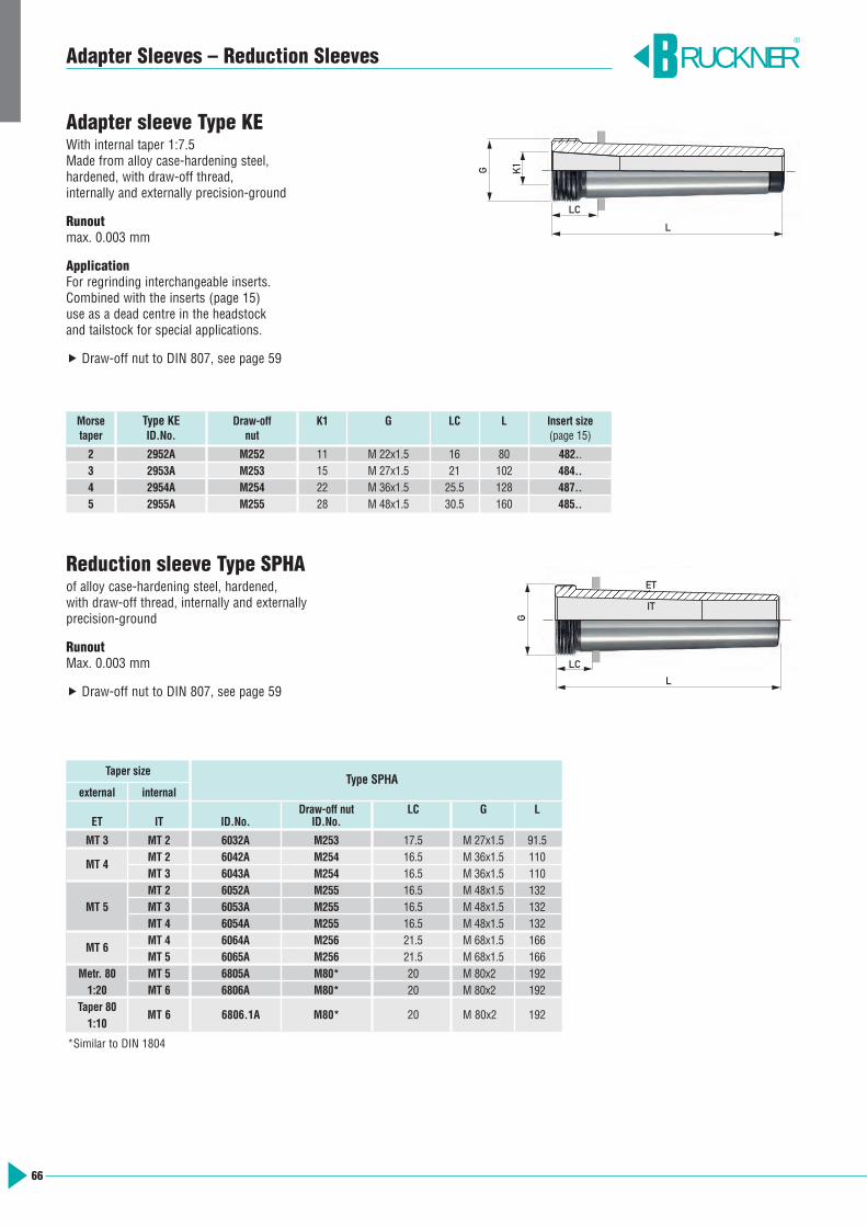
Adapter Sleeves – Reduction Sleeves
Morse Type KE Draw-off K1 G LC L Insert sizetaper ID.No. nut (page 15)
2 2952A M252 11 M 22x1.5 16 80 482..3 2953A M253 15 M 27x1.5 21 102 484..4 2954A M254 22 M 36x1.5 25.5 128 487..5 2955A M255 28 M 48x1.5 30.5 160 485..
Taper sizeType SPHA
external internalDraw-off nut LC G L
ET IT ID.No. ID.No.
MT 3 MT 2 6032A M253 17.5 M 27x1.5 91.5
MT 4MT 2 6042A M254 16.5 M 36x1.5 110MT 3 6043A M254 16.5 M 36x1.5 110MT 2 6052A M255 16.5 M 48x1.5 132
MT 5 MT 3 6053A M255 16.5 M 48x1.5 132MT 4 6054A M255 16.5 M 48x1.5 132
MT 6MT 4 6064A M256 21.5 M 68x1.5 166MT 5 6065A M256 21.5 M 68x1.5 166
Metr. 80 MT 5 6805A M80* 20 M 80x2 1921:20 MT 6 6806A M80* 20 M 80x2 192
Taper 801:10
MT 6 6806.1A M80* 20 M 80x2 192
*Similar to DIN 1804
Adapter sleeve Type KEWith internal taper 1:7.5Made from alloy case-hardening steel, hardened, with draw-off thread, internally and externally precision-ground
Runoutmax. 0.003 mm
ApplicationFor regrinding interchangeable inserts. Combined with the inserts (page 15) use as a dead centre in the headstock and tailstock for special applications.
Draw-off nut to DIN 807, see page 59
Reduction sleeve Type SPHAof alloy case-hardening steel, hardened, with draw-off thread, internally and externallyprecision-ground
RunoutMax. 0.003 mm
Draw-off nut to DIN 807, see page 59
G K1
L
LC
RUCKNER®
G
L
LC
ET
IT
66

RUCKNER®
CARBIDOR® – The Driving Coating
CARBIDOR®
is tungsten carbide based coating especially developed to drive workpieces.The coating can be applied to all hard tool steels and particularly featureswear resistance, high coefficient of friction and low coating thickness.
CARBIDOR® is applied to enhance friction between workpiece and clampingtool. In this case almost all shapes can be coated. To drive by a workpiececentre, the centre must be ≥ 4 x 2 mm. The axial pressure should be ashigh as possible.
CARBIDOR® coated tool steel dead centres for gear cutting, fine turning, finishing, measuring/inspection
CARBIDOR® featuresPermanent connection with the carrier material, impact resistant
High hardness 74 – 78 HRCSurface roughness:CARBIDOR®-F Rz 15 µmCARBIDOR®-M Rz 17 µmCARBIDOR®-G Rz 19 µmCoating thickness approx. 25 µm
In case of wear recoating is possible.
CARBIDOR® coating is applicable to
BRUCKNER standard tool steel deadcentres (pages 63 – 65)
tool steel dead centres in specialdesign
all soft, hardened components of toolsteel and stainless steel, jaws, spheres,collets etc.
Please pay attention to our safety tips for process reliability of drivingcoatings.www.karlbruckner.de/prse
CARBIDOR® surface structure
67
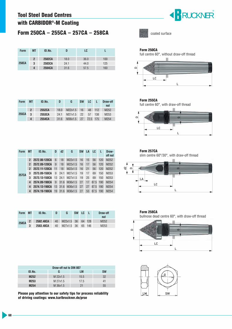
68
Tool Steel Dead Centreswith CARBIDOR®-M Coating
Form 250CA – 255CA – 257CA – 258CA
Form 250CA full centre 60°, without draw-off thread
Form 257CAslim centre 60°/30°, with draw-off thread
Form 255CAfull centre 60°, with draw-off thread
Form 258CAbullnose dead centre 60°, with draw-off thread
Form MT ID.No. D LC L
2 2502CA 18.0 36.0 1003 2503CA 24.1 44.0 1254 2504CA 31.6 57.5 160
250CA
Form MT ID.No. D d2 G SW LA LC L Draw-off nut
2 2572.06-120CA 6 18 M22x1.5 16 15 56 120 M2522 2572.09-120CA 9 18 M22x1.5 16 17 56 120 M2522 2572.11-120CA 11 18 M22x1.5 16 21 56 120 M2523 2573.09-150CA 9 24.1 M27x1.5 19 17 69 150 M2533 2573.13-150CA 13 24.1 M27x1.5 19 25 69 150 M2534 2574.09-190CA 9 31.6 M36x1.5 27 17 87.5 190 M2544 2574.13-190CA 13 31.6 M36x1.5 27 27 87.5 190 M2544 2574.19-190CA 19 31.6 M36x1.5 27 53 87.5 190 M254
257CA
Form MT ID.No. D G SW LC L Draw-offnut
2 2552CA 18.0 M22x1.5 16 48 112 M2523 2553CA 24.1 M27x1.5 22 57 138 M2534 2554CA 31.6 M36x1.5 27 72.5 175 M254
255CA
Form MT ID.No. D G SW LC L Draw-offnut
2 2582.40CA 40 M22x1.5 36 64 128 M2523 2583.40CA 40 M27x1.5 36 65 146 M253
258CA
RUCKNER®
LM SW
G
Draw-off nut to DIN 807ID.No. G LM SW
M252 M 22x1.5 15.5 32M253 M 27x1.5 17.5 41M254 M 36x1.5 21 55
D
L
LC
DL
LC
G
d2 D
LC
LA
L
G
D
L
LC
G
coated surface
Please pay attention to our safety tips for process reliability of driving coatings: www.karlbruckner.de/prse
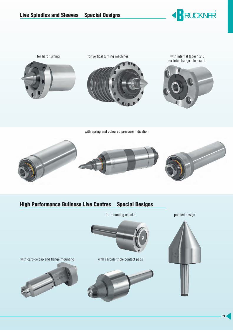
Live Spindles and Sleeves Special Designs
High Performance Bullnose Live Centres Special Designs
RUCKNER®
for vertical turning machines
for mounting chucks pointed design
with carbide triple contact pads
with internal taper 1:7.5for interchangeable inserts
with carbide cap and flange mounting
for hard turning
with spring and coloured pressure indication
69
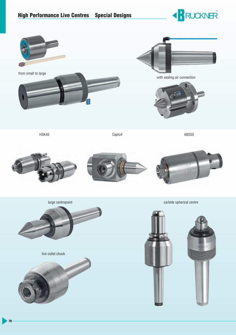
70
High Performance Live Centres Special Designs RUCKNER®
with sealing air connection
HSK40
from small to large
live collet chuck
large centrepoint carbide spherical centre
ABS50Capto4

71
Carbide Dead Centres Special Designs
flange mounted centres, flat and full
flange mounted carbide centres with flat and full carbide
open centre bore with Morse taper mounting
RUCKNER®
carbide ball∅ 52 ∅ 20
steep taperwith full carbide
HSK with full carbide
12° driving ring
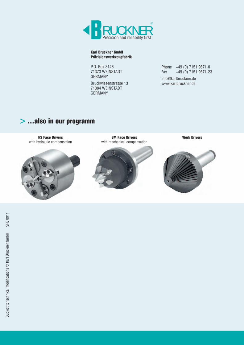
...also in our programm>
Subject to technical m
odifications © Karl Bruckner GmbH SPE 0911
HS Face Driverswith hydraulic compensation
Work DriversSM Face Driverswith mechanical compensation
Karl Bruckner GmbH Präzisionswerkzeugfabrik
P.O. Box 314671373 WEINSTADTGERMANY
Bruckwiesenstrasse 1371384 WEINSTADTGERMANY
Phone +49 (0) 7151 9671-0Fax +49 (0) 7151 9671-23
RUCKNERPrecision and reliability first
®