Embed Size (px)
Citation preview

R
Retract unit mount2 layers of 3mm liteply
between 0.8mm birch ply(Total thickness 7.6mm) Rudder post
5mm balsa
Seat horn on 3mm balthen edge with balsa to
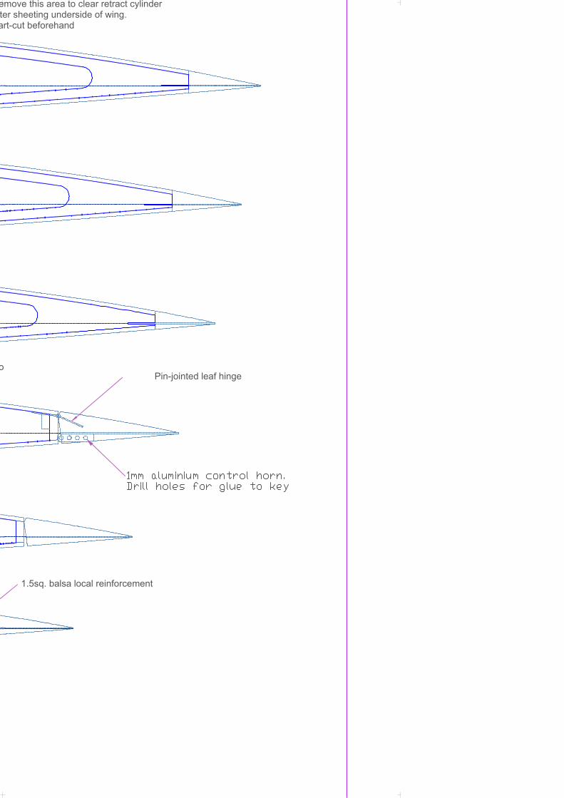
Rudder h1mm alum

R1
R2
R3
R4
R5
R6
R7
R8
R9
R10
Fin & rudder ribs1.5mm balsa
Sand slots for hinges before glueingboth halves of spar together
Round-off to 'soften' edge
R8
Also applicable to tailplane
Rudder perimeter frame0.4mm ply
alsa above R2to support covering
r hornminium
Horn seat

T1
T2
T3
T4
T5
T6
T7
T8
T9
Rudder trim-tab core0.4mm ply
Tailplane & elevator ribs1.5mm balsa(Two sets required)
3mm balsa between T1 & T1
Cut centre away afterplanking wing root fairing
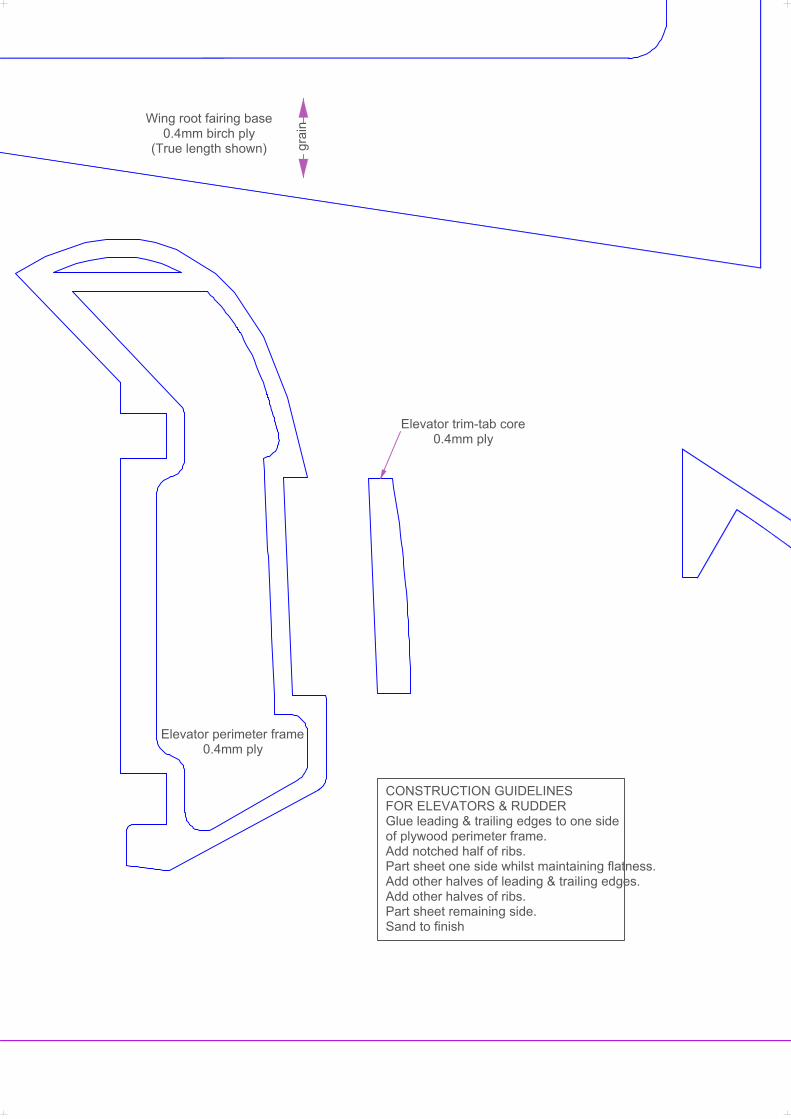
Elevator trim-tab core0.4mm ply
grai
nWing root fairing base0.4mm birch ply
(True length shown)
Elevator perimeter frame0.4mm ply
CONSTRUCTION GUIDELINESFOR ELEVATORS & RUDDERGlue leading & trailing edges to one sideof plywood perimeter frame.Add notched half of ribs.Part sheet one side whilst maintaining flatness.Add other halves of leading & trailing edges.Add other halves of ribs.Part sheet remaining side.Sand to finish

SPITFIRFirst in a series of 1/
SHEET 2 DesignedFor 500/600
Wing-tip core0.4mm ply
R
MkIX
Carburettor air intakeHollowed block balsa
RE/9th scale WW2 aircraft
2000ed by Dave Philpotts0 geared electric motors
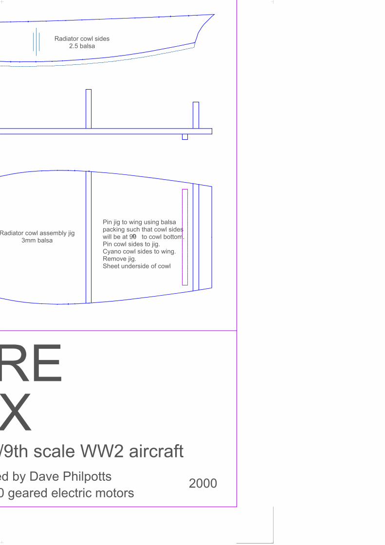
Radiator cowl sides2.5 balsa
Radiator cowl assembly jig3mm balsa
o
Pin jig to wing using balsapacking such that cowl sideswill be at 90 to cowl bottom.Pin cowl sides to jig.Cyano cowl sides to wing.Remove jig.Sheet underside of cowl
X

Wing centre section assembly jig2-off 10mm balsa
Use in conjunction with 2 lengths of3mm dia. piano wire approx. 250 long
Exit holes for servo leads &u/c. retract tubes in top surface
W3 W2 W1
60.0000
for this length
Cut lower spar here afterboxing in around retract unit
Under-wing fairing8mm balsa

W3 W4 W5W1 W2
3mm hard balsa gusset(Replaces lower spar in this area)
Wheel-well from 2 laminations of 1mm balsaglued together using impact adhesive.Grain vertical.Cut slot to clear u/c. leg and retract cylinder
Trapan circular cutoutin underside wing sheetbefore assembly
2.5mm balsa full depth of wingeach side of undercarriage leg aperture.Start by making card template
3mm sq. against gusset & rib
PLAN VIEW OF WINGUPPER SHEETING NOT SHOWN
Alternative shrouded hinge design.Requires 5mm thick fin post.Also applicable to tailplane
it

W6 W7 W8 W9
Servo accessUnderside only
(Size to suit servo)
Spars 3mm sq. hard balsa
2.5mm balsa false lHeat inside to assiscurvature around rib
Leading edge from2 laminations of 3mm balsa
Cannon from aluminium tube & balsa
2.4mboth
W10 W11 W12
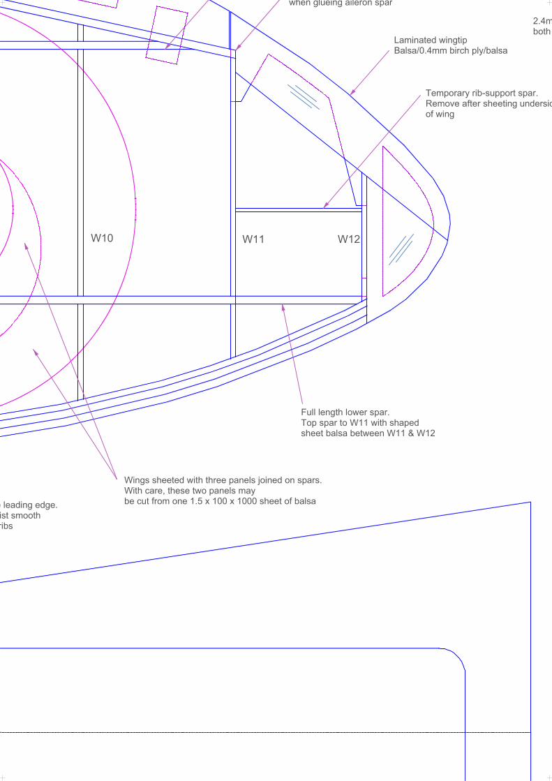
Full length lower spar.Top spar to W11 with shapedsheet balsa between W11 & W12
e leading edge.ist smoothribs
Laminated wingtipBalsa/0.4mm birch ply/balsa
when glueing aileron spar
Temporary rib-support spar.Remove after sheeting undersidof wing
Wings sheeted with three panels joined on spars.With care, these two panels maybe cut from one 1.5 x 100 x 1000 sheet of balsa

W5
W6
W7
W8
W9
W10
W11
W12
mm balsa full depth of wingh sides of undercarriage slot
Cutout to suit servo
RemaftePar
Remove this area to clear wheel wellafter sheeting underside of wing.Part-cut beforehand
side
o
emove this area to clear retract cylinderter sheeting underside of wing.art-cut beforehand
1.5sq. balsa local reinforcement
Pin-jointed leaf hinge

Sand lig
Centre section sheeting 2.5mm balsa
3mm ba(Not sh
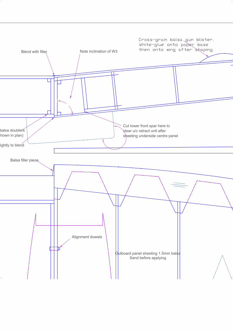
Blend with filler
lightly to blend
84°
Note inclination of W3
Alignment dowels
Balsa filler piece
balsa doublersshown in plan)
Cut lower front spar here toclear u/c retract unit aftersheeting underside centre panel
Outboard panel sheeting 1.5mm balsaSand before applying
270°

Wing washout jig3mm balsa
Laminated trailing edgeBalsa/0.4mm birch ply/balsa

Remafter
2.5mm thick balsaunit to support un& end of lower sp
Note flat underside to wing panels
Reduce thickness of rear spars at ends
Dihedral jig
Align underside rear of W11 with inboard ribswhen glueing aileron spar
Laminated aileronBalsa/0.4mm birch ply/balsaTack-glue to wing when sanding to shape
IMPORTANT! ARemove this are1.5mm sheetingrib profile and ceRemove finally aunderside of cen
W4
W1
W2
W3
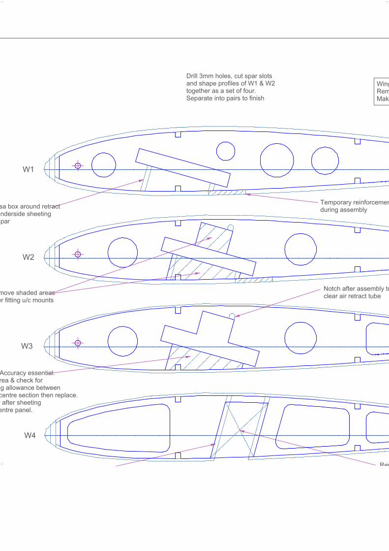
Drill 3mm holes, cut spar slotsand shape profiles of W1 & W2together as a set of four.Separate into pairs to finish
Temporary reinforcemenduring assembly
move shaded areaser fitting u/c mounts
Rem
sa box around retractnderside sheeting
spar
WingRemMake
Notch after assembly toclear air retract tube
Accuracy essential.rea & check forg allowance betweencentre section then replace.
y after sheetingentre panel.
ent
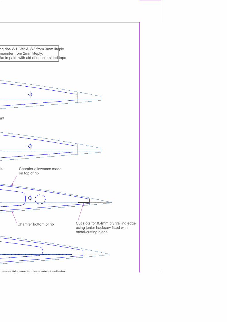
Cut slots for 0.4mm ply trailing edgeusing junior hacksaw fitted withmetal-cutting blade
Chamfer bottom of rib
Chamfer allowance madeon top of rib
emove this area to clear retract cylinder
ng ribs W1, W2 & W3 from 3mm liteply.mainder from 2mm liteply.
ake in pairs with aid of double-sided tape
to