Embed Size (px)
Citation preview
RUGGED D-SUB CONNECTOR SERIES
WHITE PAPER | DURABLE, HIGH SPEED CONNECTORS

1
CONTENTS
2 RUGGED D-SUB CONNECTORS
2 Background
3 Terms
4 Competitor Comparison
5 Reverse Gender Design
5 Rugged D-Sub Connector Design
6 Six-Position Keyed Jack Post
7 Keyed Rugged D-Sub Mating Sequence
7 Keyed Jack Post & Back Shell Accessories
8 PERFORMANCE
8 Specifications
9 Eye Pattern
10 Test Capabilities
11 INSTALLATION INSTRUCTIONS
11 Tools

2
RUGGED D-SUB CONNECTORS
BACKGROUND Smiths Connectors offers a complete line of differential Twinax and Quadrax connectors, contacts, and cable assemblies for high speed Ethernet, Firewire, and Fibre Channel applications. Twinax and Quadrax connectors offer superior performance in high speed matched impedance data-on-demand applications. The signal to signal and signal to shield characteristic impedance is maintained throughout the connector pair. Smiths Connectors manufactures connectors for the following protocols:
Fibre Channel Ethernet: 10 Base-T, 100 Base-T, 1000 Base-T Firewire: IEEE 1394a and 1394b USB, DVI, and Infiniban

3
The Twinax / Quadrax Contact consists of an outer shield with four inner conductors (two for Twinax) paired orthogonally forming two 100 Ohm controlled impedance differential pairs. The inner contacts are within a size 9 keyed body. An alignment key is machined onto the body of the contact to insure that the contact is anti-rotational. The design engineer’s job is to ensure the Twinax / Quadrax contact maintains constant impedance and that each and every discontinuity is properly compensated to minimize reflections and preserve the signal integrity. The first eye pattern shows a contact that was not designed for constant impedance through the entire contact. The second eye pattern shows a contact that was designed with a constant impedance of 100 Ohms through the entire contact.
EYE PATTERN WITHOUT 100 OHM MATCH IMPEDANCE QUADRAX AT 1 Gbps
EYE PATTERN WITH 100 OHM MATCH IMPEDANCE QUADRAX AT 1 Gbps
TERMS
Signal Integrity Ensuring properly shaped pulses reach the receiver Eye Pattern A graph which overlays thousands of pulses as an easy way
to evaluate signal integrity Skew Difference in time delay between differential signals paths Jitter Noise induced timing error
Eye Lash Keep out region Eye Lash Keep out region

4
COMPETITOR COMPARISON Comparison of Smiths Connectors | Smiths Connectors’ Quadrax design against a competitive offering
Competitor connector performance is below the 100±10 Ohm threshold TDR (Time-Doman Reflectometer) traces show the following:
Inductive spike as the signal passes through the cable to contact crimp interface A capacitive drop (competitor’s contact) as the signal passes through the contact body A second inductive spike as the signal passes through the contact to cable crimp
interface (cable to cable application) A capacitive drop as the signal passes through the PCB tails and into the plated thru-holes of the PCB
All four contact configurations support a 250 Mbps signal dependent on electronic system design / budget (the connector looks like a single lumped impedance at this speed). The competitor’s cable to PCB contact pair is likely to cause a signal integrity issue at higher data rates > 1 GPS (Gigabit Ethernet) speed (the discrete segments of the contact are visible at that signal speed and above). Twinax / Quadrax contacts offer several advantages for high data transfer rates, low power consumption and excellent EMI compatibility:
Two or four strategically spaced inner contacts form two 100 ohm matched impedance differential pairs. Outer contact has rugged wall section. Available in size 9 crimp termination style. Size 9 pin also available as either straight or right angle PC tails.
Requirement 100 ± 10 Ω

5
REVERSE GENDER DESIGN In a traditional Quadrax design, the four inner pin contacts within the contact protrude from the insulator surface. Because of the small gage of the contact pins, there is potential for the pin contacts to be bent or damaged during assembly and handling. This could lead to problems when the connectors are mated as contacts with just the smallest misalignment could experience breaking or bending pins. In some cases the pins could damage the mating socket contact or puncture the mating contact dielectric material. To avoid this potential problem, Smiths Connectors’ Quadrax contacts’ design is reverse gender. The inner Quadrax pin is recessed with the dielectric material. The inner socket contact is in the exposed air dielectric. Benefits of reverse gender design:
Better blind mate capability Reduced chance of bent inner pins Larger, heat-treated rigid socket contacts protruding
In the High Speed Rugged D-Sub receptacle, the termination style can be a cable mount crimp version, straight PC tail or right angle PC tail. In the straight and right angle pin PC tail version the contacts are included when the High Speed D-Sub receptacle connector is purchased. The termination style of the Twinax or Quadrax socket designed for the High Speed plug is a cable mount crimp version.
RUGGED D-SUB CONNECTOR DESIGN
1. The plug and receptacle are supplied with an aluminum nickel plated housing.
2. The plug is designed with integrated multi-finger contact engagement for superior EMI shielding and low contact resistance.
3. Standard non-keyed insert arrangements offered: 2, 4, 6, 8, 12, 16 and 21 way (hybrid options available).
4. Standard keyed insert arrangements offered: 2, 4, 6 and 8.
5. Six-position keyed and non-keyed jack posts accessory hardware available.

6
SIX-POSITION KEYED JACK POST To ensure that the correct High Speed connectors are mated to address specific wiring requirements and keying combinations, a keyed jack post was incorporated into the design. The six position keyed jack post allows for 36 possible keying combinations ensuring the correct High Speed Plug is mated to the correct High Speed Receptacle. With the use of the keyed D-Sub, the customer can be certain the correct plug will be mated to the proper receptacle if there are multiple receptacles on their box. To set the key to the desired position:
1. Loosen the nut located in the back of the flange.
2. Rotate the jack screw to the desired position (see chart).
3. Tighten the nut to 5 to 8 inch pounds.
KEY POSITION
RECEPTACLE PLUG
Left Right Left Right
1 A A A A
2 A B F A
“ “ “ “ “
23 D E C D
7
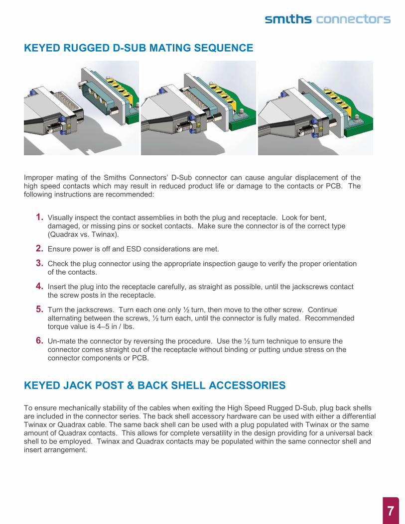
KEYED RUGGED D-SUB MATING SEQUENCE
Improper mating of the Smiths Connectors’ D-Sub connector can cause angular displacement of the high speed contacts which may result in reduced product life or damage to the contacts or PCB. The following instructions are recommended:
1. Visually inspect the contact assemblies in both the plug and receptacle. Look for bent, damaged, or missing pins or socket contacts. Make sure the connector is of the correct type (Quadrax vs. Twinax).
2. Ensure power is off and ESD considerations are met.
3. Check the plug connector using the appropriate inspection gauge to verify the proper orientation of the contacts.
4. Insert the plug into the receptacle carefully, as straight as possible, until the jackscrews contact the screw posts in the receptacle.
5. Turn the jackscrews. Turn each one only ½ turn, then move to the other screw. Continue alternating between the screws, ½ turn each, until the connector is fully mated. Recommended torque value is 4–5 in / lbs.
6. Un-mate the connector by reversing the procedure. Use the ½ turn technique to ensure the connector comes straight out of the receptacle without binding or putting undue stress on the connector components or PCB.
KEYED JACK POST & BACK SHELL ACCESSORIES To ensure mechanically stability of the cables when exiting the High Speed Rugged D-Sub, plug back shells are included in the connector series. The back shell accessory hardware can be used with either a differential Twinax or Quadrax cable. The same back shell can be used with a plug populated with Twinax or the same amount of Quadrax contacts. This allows for complete versatility in the design providing for a universal back shell to be employed. Twinax and Quadrax contacts may be populated within the same connector shell and insert arrangement.

8
PERFORMANCE
SPECIFICATIONS
Mechanical, Environmental and Electrical Parameters
Temperature Rating -65°C To +165°C
Corrosion MIL-STD-202 METHOD 101, Test Condition B
Shock MIL-STD-202 Method 213, Test Condition B
Vibration MIL-STD-202 Method 204, Test Condition B
Thermal Shock MIL-STD-202 Method 107, Test Condition B
Durability 500 Mating Cycles / Minute
Electrical Specifications
Dielectric Withstanding Voltage 250 V DC max
Insulation Resistance 5.000 megaohms/min.
Contact Current Rating 3.0 Amps DC min.
Bandwidth Up to 10 GHz
Data Rates Exceeding 5 Gbps
Differential Pair Cable Impedance 100 Ohm ± 10 Ohms
9
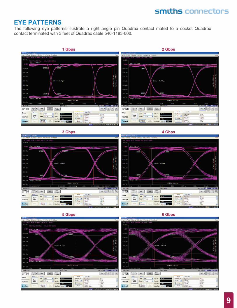
EYE PATTERNS The following eye patterns illustrate a right angle pin Quadrax contact mated to a socket Quadrax contact terminated with 3 feet of Quadrax cable 540-1183-000.
1 Gbps 2 Gbps
3 Gbps 4 Gbps
5 Gbps 6 Gbps
10
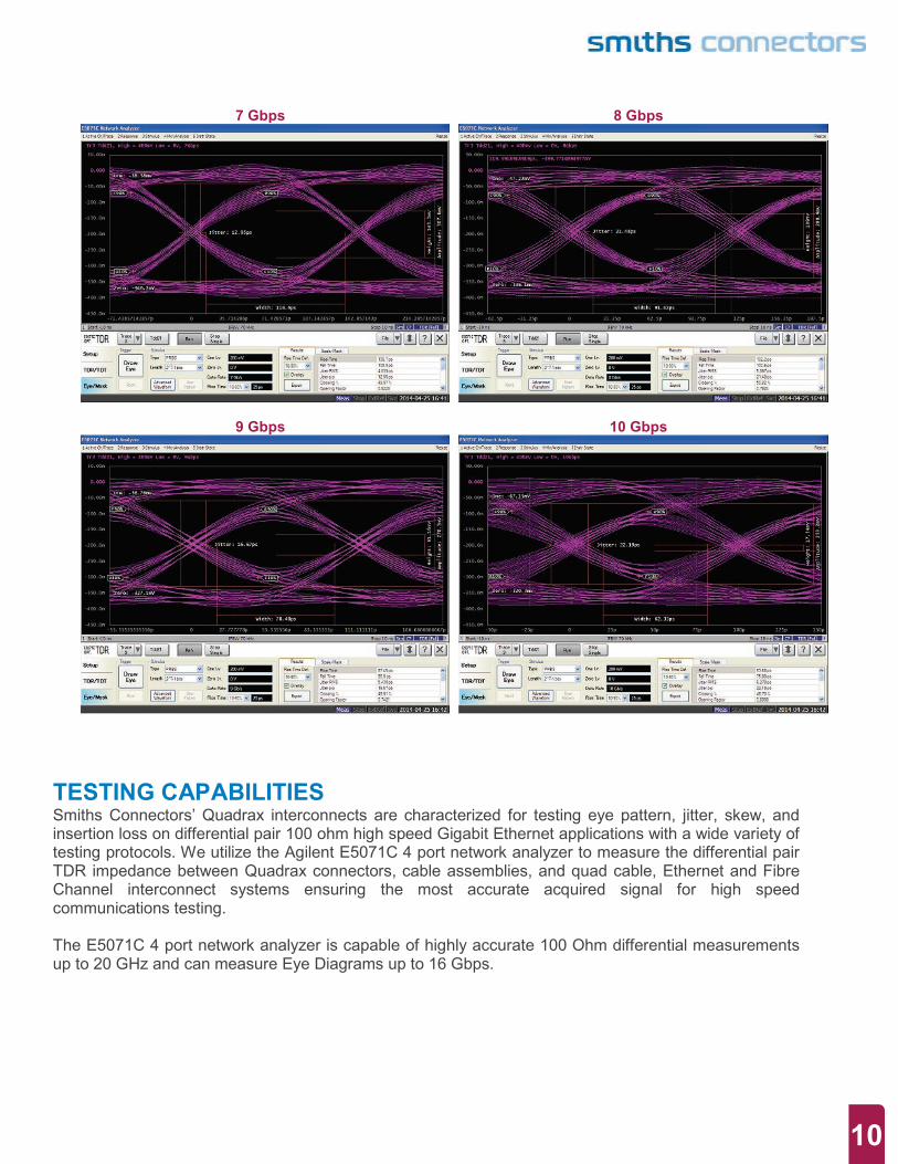
7 Gbps 8 Gbps
9 Gbps 10 Gbps
TESTING CAPABILITIES Smiths Connectors’ Quadrax interconnects are characterized for testing eye pattern, jitter, skew, and insertion loss on differential pair 100 ohm high speed Gigabit Ethernet applications with a wide variety of testing protocols. We utilize the Agilent E5071C 4 port network analyzer to measure the differential pair TDR impedance between Quadrax connectors, cable assemblies, and quad cable, Ethernet and Fibre Channel interconnect systems ensuring the most accurate acquired signal for high speed communications testing. The E5071C 4 port network analyzer is capable of highly accurate 100 Ohm differential measurements up to 20 GHz and can measure Eye Diagrams up to 16 Gbps.

11
INSTALLATION INSTRUCTIONS
TOOLS The following tools have been designed and are recommended when terminating the Twinax or Quadrax connectors to cable.
T-2177-1 To ensure the insulation of the cable is at
the correct dimension.
T-2177-2 To ensure the wires are cut at the
correct dimension.
T-2172 To ensure the wires are cut to the same dimensions as stated within the
assembly instructions. All wires should be seen through the opening in T-2172. The use of a magnifying glass and backlight are highly recommended.

12
PLUG INSPECTION TOOL: ST-2031 through ST-2031 These tools will verify the Quadrax and Twinax sockets and socket contacts in
the plug connector are aligned within the required assembly tolerances.
PASS FAIL
1. Inspect the fixture to ensure the proper device is being used. Verify that the number of pins on the fixture matches the number of pins on the contacts.
2. Insert the connector into the fixture. Resistance will be felt as the EMI spring on the connector is compressed. Mate the fixture with the connector fully.
3. The pins on the back of the fixture will indicate the pass/fail result. If the pins remain inside the fixture, the test is passed. If any of the pins extend from the fixture, the test fails.
4. Remove the fixture and visually inspect the plug pins for any damage.
Soldering Alignment tool: Part Numbers ST-1031 through ST-1038. Use to align contacts properly when soldering receptacles with PC tails.

13
SMITHS CONNECTORS GLOBAL SUPPORT
AMERICAS Costa Mesa, CA 1.714.371.110 [email protected] Hudson, MA 1.978.568.0451 [email protected] Kansas City, KS 1.913.342.5544 [email protected]
EUROPE France 33.2.3296.9176 [email protected] Germany 49.991.250.120 [email protected] Italy 39.010.60361 [email protected] United Kingdom 44.20.8450.8033 [email protected] ASIA
Bangalore, India 91.80.2535.7351/52 [email protected] Shanghai, China 86.21.3318.4650 [email protected] Singapore 65.6846.1655 [email protected] Suzhou, China 86.512.6273.1188 [email protected]
FOR MORE INFORMATION | smithsconnectors.com
Disclaimer 2014 All of the information in this test report is believed to be accurate at the time of printing. It is recommended, however, that users independently evaluate the suitability of each product for their intended application and be sure that each product is properly installed, used and maintained to achieve desired results. Smiths Connectors makes no warranties as to the accuracy or completeness of the information, and disclaims any liability regarding its use. Smiths Connectors reserves the right to modify design and specifications, in order to improve quality, keep pace with technological development or meet specific production requirements. No reproduction or use without express permission of editorial and pictorial content, in any manner