Embed Size (px)
Citation preview
RULES FOR CLASSIFICATION OF
The content of thisaccepts that it is pverification servicepursuant to this docconsequences arisin
The electronic p
High Speed, Light Craft andNaval Surface Craft
PART 3 CHAPTER 4
STRUCTURES, EQUIPMENT
Hull Structural Design, Fibre Composite
and Sandwich ConstructionsJANUARY 2013
DET NORSKE VERITAS AS
service document is the subject of intellectual property rights reserved by Det Norske Veritas AS (DNV). The userrohibited by anyone else but DNV and/or its licensees to offer and/or perform classification, certification and/ors, including the issuance of certificates and/or declarations of conformity, wholly or partly, on the basis of and/orument whether free of charge or chargeable, without DNV's prior written consent. DNV is not responsible for theg from any use of this document by others.
df version of this document found through http://www.dnv.com is the officially binding version

FOREWORD
DNV is a global provider of knowledge for managing risk. Today, safe and responsible business conduct is both a licenseto operate and a competitive advantage. Our core competence is to identify, assess, and advise on risk management. Fromour leading position in certification, classification, verification, and training, we develop and apply standards and bestpractices. This helps our customers safely and responsibly improve their business performance. DNV is an independentorganisation with dedicated risk professionals in more than 100 countries, with the purpose of safeguarding life, propertyand the environment.
The Rules lay down technical and procedural requirements related to obtaining and retaining a Class Certificate. It is usedas a contractual document and includes both requirements and acceptance criteria.
© Det Norske Veritas AS January 2013
Any comments may be sent by e-mail to [email protected]
If any person suffers loss or damage which is proved to have been caused by any negligent act or omission of Det Norske Veritas, then Det Norske Veritas shall pay compensation tosuch person for his proved direct loss or damage. However, the compensation shall not exceed an amount equal to ten times the fee charged for the service in question, provided thatthe maximum compensation shall never exceed USD 2 million.In this provision “Det Norske Veritas” shall mean the Foundation Det Norske Veritas as well as all its subsidiaries, directors, officers, employees, agents and any other acting on behalfof Det Norske Veritas.

Rules for High Speed, Light Craft and Naval Surface Craft, January 2013Pt.3 Ch.4 Changes – Page 3
CHANGES
General
This document supersedes the July 2012 edition.
Text affected by the main changes in this edition is highlighted in red colour. However, if the changes involvea whole chapter, section or sub-section, normally only the title will be in red colour.
Main changes coming into force 1 July 2013
• Sec.7 Stiffeners, Web Frames and Girders— Sub-section element B300 has been revised for clarification.— In item C402, Fig.2 has been revised.
In addition to the above stated main changes, editorial corrections may have been made.
Editorial Corrections
DET NORSKE VERITAS AS
Rules for High Speed, Light Craft and Naval Surface Craft, January 2013 Pt.3 Ch.4 Contents – Page 4
CONTENTS
Sec. 1 Structural Principles .......................................................................................................................... 7
A. Definitions ...................................................................................................................................................................... 7A 100 Application............................................................................................................................................................ 7A 200 Symbols ................................................................................................................................................................ 7
B. Documentation .............................................................................................................................................................. 7B 100 Required documentation ....................................................................................................................................... 7
C. Structural Calculations................................................................................................................................................. 8C 100 Design principles .................................................................................................................................................. 8C 200 Calculation levels.................................................................................................................................................. 8C 300 Calculation basis ................................................................................................................................................... 8C 400 Simplified calculation methods ............................................................................................................................ 8C 500 Laminate calculation method................................................................................................................................ 9C 600 Detailed laminate calculations ............................................................................................................................ 10C 700 Allowable stresses and deflections ..................................................................................................................... 10C 800 Direct calculations by finite element methods.................................................................................................... 10
D. Bottom Structures ....................................................................................................................................................... 10D 100 Longitudinal stiffeners ........................................................................................................................................ 10D 200 Web frames ......................................................................................................................................................... 11D 300 Longitudinal girders............................................................................................................................................ 11D 400 Engine girders ..................................................................................................................................................... 11D 500 Double bottom .................................................................................................................................................... 11D 600 Bow impact protection........................................................................................................................................ 11
E. Side Structures ............................................................................................................................................................ 12E 100 Stiffeners ............................................................................................................................................................. 12
F. Deck Structure............................................................................................................................................................. 12F 100 Longitudinal stiffeners ........................................................................................................................................ 12F 200 Bulwarks ............................................................................................................................................................. 12
G. Bulkhead Structures ................................................................................................................................................... 13G 100 Watertight bulkheads .......................................................................................................................................... 13G 200 Supporting bulkheads ......................................................................................................................................... 13
H. Superstructures and Deckhouses............................................................................................................................... 13H 100 Definitions .......................................................................................................................................................... 13H 200 Structural continuity ........................................................................................................................................... 13
Sec. 2 Manufacturing.................................................................................................................................. 14
A. General Requirements ................................................................................................................................................ 14A 100 Introduction......................................................................................................................................................... 14
B. Storage of Raw Materials ........................................................................................................................................... 14B 100 Storage ................................................................................................................................................................ 14B 200 Manufacturing premises and conditions ............................................................................................................. 14
C. Production Procedures and Workmanship .............................................................................................................. 15C 100 General requirements .......................................................................................................................................... 15C 200 Sandwich lay-up ................................................................................................................................................. 15C 300 Manual lamination .............................................................................................................................................. 16C 400 Vacuum assisted resin transfer moulding (VARTM) and vacuum-bagging ...................................................... 16C 500 Spray moulding................................................................................................................................................... 17C 600 Curing ................................................................................................................................................................. 17C 700 Secondary bonding ............................................................................................................................................. 17C 800 Adhesive Bonding............................................................................................................................................... 17
D. Quality Assurance and Quality Control ................................................................................................................... 18D 100 Quality assurance ................................................................................................................................................ 18D 200 Quality control .................................................................................................................................................... 18D 300 Production testing ............................................................................................................................................... 18
Sec. 3 Materials ........................................................................................................................................... 20
A. General ......................................................................................................................................................................... 20A 100 Introduction......................................................................................................................................................... 20A 200 Material certificates ............................................................................................................................................ 20
DET NORSKE VERITAS AS
Rules for High Speed, Light Craft and Naval Surface Craft, January 2013 Pt.3 Ch.4 Contents – Page 5
B. Application of Materials ............................................................................................................................................. 20B 100 Hull and superstructure ....................................................................................................................................... 20B 200 Tanks for storage of liquids ................................................................................................................................ 20B 300 Surface coating.................................................................................................................................................... 20
C. Material Properties and Qualification Testing ........................................................................................................ 20C 100 Basis for strength calculations ............................................................................................................................ 20C 200 Qualification testing............................................................................................................................................ 21
Sec. 4 Hull Girder Strength........................................................................................................................ 22
A. General ......................................................................................................................................................................... 22A 100 Introduction......................................................................................................................................................... 22A 200 Definitions .......................................................................................................................................................... 22
B. Vertical Bending Strength.......................................................................................................................................... 22B 100 Hull section modulus requirement ...................................................................................................................... 22B 200 Effective section modulus................................................................................................................................... 23B 300 Hydrofoil on foils................................................................................................................................................ 23B 400 Longitudinal structural continuity ...................................................................................................................... 23B 500 Openings ............................................................................................................................................................. 24
C. Shear Strength............................................................................................................................................................. 24C 100 Cases to be investigated ...................................................................................................................................... 24
D. Cases to be investigated .............................................................................................................................................. 24D 100 Inertia induced loads ........................................................................................................................................... 24
E. Transverse Strength of Twin Hull Craft................................................................................................................... 24E 100 Transverse strength ............................................................................................................................................. 24E 200 Allowable stresses............................................................................................................................................... 25
Sec. 5 Sandwich Panels ............................................................................................................................... 26
A. General ......................................................................................................................................................................... 26A 100 Introduction......................................................................................................................................................... 26
B. Bending ........................................................................................................................................................................ 27B 100 Application.......................................................................................................................................................... 27B 200 Normal stresses in skin laminates and core shear stresses.................................................................................. 27B 300 Local skin buckling............................................................................................................................................. 29B 400 Deflections .......................................................................................................................................................... 29B 500 Allowable stresses and deflections ..................................................................................................................... 31
Sec. 6 Stiffened Single Skin Construction................................................................................................. 32
A. General ......................................................................................................................................................................... 32A 100 Introduction......................................................................................................................................................... 32A 200 Minimum requirements for structural single skin plates .................................................................................... 32
B. Laterally Loaded Single Skin Laminates.................................................................................................................. 32B 100 Assumptions........................................................................................................................................................ 32B 200 Laminates exposed to lateral loads ..................................................................................................................... 33B 300 Allowable stresses and deflections (when
excluding membrane effects).............................................................................................................................. 34B 400 Laminates exposed to combined bending and membrane stresses ..................................................................... 34B 500 Allowable stresses and deflections (when including membrane effects) ........................................................... 34
Sec. 7 Stiffeners, Web Frames and Girders ............................................................................................. 35
A. General ......................................................................................................................................................................... 35A 100 Introduction......................................................................................................................................................... 35A 200 Continuity of strength members ......................................................................................................................... 35
B. Bending and Shear ...................................................................................................................................................... 35B 100 General................................................................................................................................................................ 35B 200 Loads................................................................................................................................................................... 35B 300 Effective flange................................................................................................................................................... 36B 400 Effective web ...................................................................................................................................................... 37B 500 Effective bond area ............................................................................................................................................. 37B 600 Strength requirements ......................................................................................................................................... 37
C. Complex Girder Systems............................................................................................................................................ 39C 100 General................................................................................................................................................................ 39C 200 Calculation methods ........................................................................................................................................... 39
DET NORSKE VERITAS AS
Rules for High Speed, Light Craft and Naval Surface Craft, January 2013 Pt.3 Ch.4 Contents – Page 6
C 300 Design load conditions........................................................................................................................................ 39C 400 Allowable stresses............................................................................................................................................... 39
Sec. 8 Bonded Joints.................................................................................................................................... 42
A. General ......................................................................................................................................................................... 42A 100 Application.......................................................................................................................................................... 42
B. Design ........................................................................................................................................................................... 42B 100 Design of bonded joints ...................................................................................................................................... 42
C. Qualification ................................................................................................................................................................ 43C 100 Qualification tests ............................................................................................................................................... 43
Sec. 9 Bolted Connections........................................................................................................................... 44
A. General ......................................................................................................................................................................... 44A 100 Introduction......................................................................................................................................................... 44
B. In-plane Loads (Shear Connections) ......................................................................................................................... 44B 100 Introduction......................................................................................................................................................... 44B 200 Minimum requirements....................................................................................................................................... 45
C. Out-of-plane Loads ..................................................................................................................................................... 46C 100 General ............................................................................................................................................................... 46
D. Inserts and Attachments............................................................................................................................................. 46D 100 General................................................................................................................................................................ 46
Sec. 10 Buckling............................................................................................................................................. 47
A. General ......................................................................................................................................................................... 47A 100 General................................................................................................................................................................ 47
B. Single Skin Panels ....................................................................................................................................................... 47B 100 Single skin panels ............................................................................................................................................... 47
C. Sandwich Panels .......................................................................................................................................................... 48C 100 Sandwich panels ................................................................................................................................................. 48
D. Beams, Girders and Stringers.................................................................................................................................... 49D 100 Beams, girders and stringers ............................................................................................................................... 49
E. Stiffened Plate Field .................................................................................................................................................... 49E 100 Stiffened plate field............................................................................................................................................. 49
F. Columns ....................................................................................................................................................................... 49F 100 Columns .............................................................................................................................................................. 49
DET NORSKE VERITAS AS
Rules for High Speed, Light Craft and Naval Surface Craft, January 2013 Pt.3 Ch.4 Sec.1 – Page 7
SECTION 1 STRUCTURAL PRINCIPLES
A. Definitions
A 100 Application
101 These rules apply to structures of fiber reinforced plastic (FRP) single skin and sandwich constructionsfor assignment of the main class. The plastics used in such applications shall be thermosets.
102 A single skin construction is considered to be a structure consisting of a FRP shell laminate supportedand stiffened locally by a system of closely spaced FRP stiffeners.
103 A sandwich construction is considered to be a structural element consisting of three components: a FRPskin laminate on each side of a low density core. It is assumed that the properties and the proportions of thecomponent materials are such that when a sandwich panel is exposed to a lateral load the bending moments arecarried by the skins and the shear forces by the core.
104 These rules do not apply of monococque constructions. Acceptance criteria for monococqueconstructions will have to be agreed in each case.
A 200 Symbols
201 The following symbols are used in the formulae in Sec.4, Sec.5, Sec.6 and Sec.7 in this Part:
t = laminate thickness in mm, either for a single skin shell or a sandwich skin laminate.tc = sandwich core thickness in mm.d = distance between centrelines of opposite skin laminates of a sandwich panel in mm.E = tensile or compressive modulus of elasticity of FRP laminate in N/mm2.EC = modulus of elasticity of core material in N/mm2 given on type approval certificate.GC = modulus of rigidity (shear modulus) of sandwich core material in N/mm2 given on type approval certificate.σ nu = ultimate normal stress in tension or compression of FRP laminate in N/mm2.σ n = normal stress in FRP laminate in N/mm2.σ c = combined bending and membrane stress in N/mm2.σ cr = critical buckling stress in N/mm2.τ = shear stress in FRP laminate in N/mm2.τult = ultimate shear stress in FRP in N/mm2.τu = ultimate shear stress of sandwich core material in N/mm2 given on type approval certificate.τc = core shear stress in laterally loaded sandwich panel in N/mm2.ω = panel deflection in mm.δ = panel deflection factor.ν = Poisson’s ratio.p = design pressure in kN/m2 as given in Ch.1.a = longest side of sandwich or single skin panel in m.b = shortest side of sandwich or single skin panel in m.
B. Documentation
B 100 Required documentation
101 The following documentation shall be submitted for plan approval:
a) Drawings as per the requirements in these rules.b) Specifications of all reinforcement fabrics.c) Specifications of all resins.d) Details of all laminates and panels: stacking sequence and the mechanical properties used for the design,
see 102 and fabrication method (e.g. manual lamination or VARTM etc.).e) Plan for qualification testing, see Sec.3 C.
All of these documents are subject to approval by DNV. Plan approval may not be initiated until all of thedocumentation has been submitted.
DET NORSKE VERITAS AS
Rules for High Speed, Light Craft and Naval Surface Craft, January 2013 Pt.3 Ch.4 Sec.1 – Page 8
102 The laminate details shall be presented in the form of a table or on a equivalent format giving thefollowing information for each laminate and panel:
a) Laminate or panel identification.b) Stacking sequence including references to specifications of reinforcement and resins.c) Engineering moduli as relevant. For orthotropic laminates the engineering moduli in the two principal
directions and the shear modulus shall be given.d) Tensile strength and compressive strength or strain.e) Shear strength.f) Fibre volume fraction.g) Laminate thickness.
103 The plan for qualification testing shall be defined in accordance with Sec.3 C. The plan can be presentedas notations on the table giving laminate details, see 102.
C. Structural Calculations
C 100 Design principles
101 The vessel shall be designed such that the load(s) are carried mainly by the fibres. The fibres shall bealigned close to the direction(s) of the main load path(s).
102 The failure mode of a laminate shall be fibre failure. Matrix failure shall be inhibited by alignment of thefibres according to 101, by having fibres in sufficient directions and by a stacking sequence avoiding fibreclusters.
103 Deviations from 101 may be accepted in local areas of details that are well proven and for minor loadsof secondary nature.
C 200 Calculation levels
201 The structural calculations may be performed in one of three different levels. The calculation level canbe chosen to best suit the purpose:Simplified calculation method: This is based on rule formulas. May be used for panels, stiffeners and girdersas indicated in the respective rule chapters.Laminate calculation method: This is based on the strain failure criteria. Typical application of this methodwould be in combination with global hull calculations, or calculations of larger structural elements using finiteelement methods.Detailed laminate calculation method: This is based on ply calculation theory and well accepted failure criteria.Typical use would be where detailed information of stresses in a local area is needed.
C 300 Calculation basis
301 The strength values and safety factors are based on ultimate strength as defined below:For laminates: Mean value of representative test data.The use of a mean value for laminates is based on the assumption that the laminates are of a consistent quality,i.e. a standard deviation of material test values is less than 7%.For core materials: Specified minimum value.The specified minimum value is defined as “Mean value – 2 standard deviations” as determined from tests. Tobe taken from Type Approval certificate.Secondary bond strength: Mean value of representative test data.It is assumed that the production can show consistent secondary bond test values.
C 400 Simplified calculation methods
401 Simplified calculation methods based on rule formula in Sec.5, Sec.6 and Sec.7 may be used inaccordance with the conditions given in the respective rule sections.
402 Allowable stresses and deflections to be used in association with the simplified calculation method aregiven in the respective sections.
DET NORSKE VERITAS AS
Rules for High Speed, Light Craft and Naval Surface Craft, January 2013 Pt.3 Ch.4 Sec.1 – Page 9
C 500 Laminate calculation method
501 A strain failure criteria for laminate strength will be accepted based on the conditions given below:
— The load is carried mainly by the fibres. A major part of load-carrying fibres are aligned close to thedirection of the main load path. The angle between the main load path and a significant part of the fibres isnever more than 25°. The failure mode is fibre failure.
— Matrix failure is inhibited by fibres in sufficient directions, and the fibres are not clustered.— The strains in the structure are calculated taking into account the laminate stiffness in all in-plane
directions. — All important load combinations for the laminate are to be considered.— Local deviations between the load path and fibres due to local stress concentrations should be considered
separately, possibly by adding local pads or strips in the local load direction.
Guidance note:Construction elements carrying the load mainly by the matrix should be avoided.A main load path is meant as a load direction giving significant strain for the laminate.
---e-n-d---of---G-u-i-d-a-n-c-e---n-o-t-e---
502 Strain failure criterionThe fiber strain in each fiber direction is to be limited by:
εi = laminate strain in direction iεuf = ultimate fibre strain, as defined belowR = safety factor against fibre failure
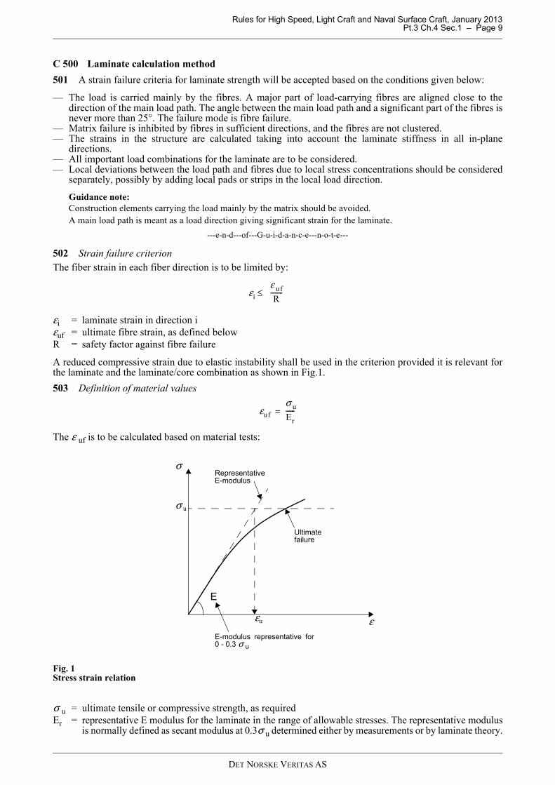
A reduced compressive strain due to elastic instability shall be used in the criterion provided it is relevant forthe laminate and the laminate/core combination as shown in Fig.1.
503 Definition of material values
The ε uf is to be calculated based on material tests:
Fig. 1Stress strain relation
σ u = ultimate tensile or compressive strength, as requiredEr = representative E modulus for the laminate in the range of allowable stresses. The representative modulus
is normally defined as secant modulus at 0.3σ u determined either by measurements or by laminate theory.
εi
ε uf
R--------≤
εuf
σ u
Er------=
ε
σ
E-modulus representative for0 - 0.3 σ u
σ u
εu
E
Ultimatefailure
Representative E-modulus
DET NORSKE VERITAS AS
Rules for High Speed, Light Craft and Naval Surface Craft, January 2013 Pt.3 Ch.4 Sec.1 – Page 10
If the laminate is built up by a combination of different mats, woven rovings etc., the ε uf may be calculatedbased on test data from the basic components.
Guidance note:In most cases the E modulus as defined in ISO 527-4 and ISO527-5 will qualify as “representative E modulus”
---e-n-d---of---G-u-i-d-a-n-c-e---n-o-t-e---
C 600 Detailed laminate calculations
601 A detailed laminate calculation may be used where detailed information of stresses or strain in a localarea is needed. The calculation may be based on ply theory and well accepted failure criteria. In order to usesuch method, it may be required to justify that the ply input data gives correct output values for all combinationsin the failure envelope.
Guidance note:One of the accepted failure criteria is the Tsai-Wu failure criterion.
---e-n-d---of---G-u-i-d-a-n-c-e---n-o-t-e---
C 700 Allowable stresses and deflections
701 The factor of safety is to be in accordance with Table C1. Core shear stresses in sandwich panels shallbe in accordance with Sec.5 B500. Panel deflections shall not be greater than specified in Sec.5 and Sec.6.
C 800 Direct calculations by finite element methods
801 Direct calculations of structural strength by use of finite element methods (FEM) may be used as analternative to the simplified calculation methods. General requirements for the analysis and programs are givenin Pt.3 Ch.9. The acceptance criteria used in connection with FEM calculations should preferably be thelaminate calculation method (strain criteria) as described in 500.
802 Safety factors for direct strength calculations shall be as specified in Table C1.
803 For detailed calculations where all stress concentrations and load combinations are represented by theFEM results, lower R factors may be agreed upon based on an evaluation of each case.
D. Bottom Structures
D 100 Longitudinal stiffeners
101 Single bottoms as well as double bottoms are normally to be longitudinally stiffened in craft built insingle skin construction. In craft with sandwich construction the bottom panel stiffening will be considered ineach individual case.
102 The longitudinals should preferably be continuous through transverse members. At their endslongitudinals are to be fitted with brackets or to be tapered out beyond the point of support.
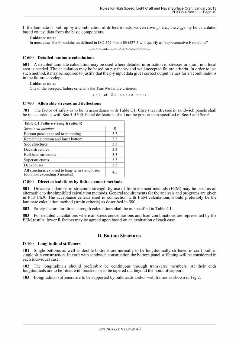
103 Longitudinal stiffeners are to be supported by bulkheads and/or web frames as shown in Fig.2.
Table C1 Failure strength ratio, RStructural member RBottom panel exposed to slamming 3.3Remaining bottom and inner bottom 3.3Side structures 3.3Deck structures 3.3Bulkhead structures 3.3Superstructures 3.3Deckhouses 3.3All structures exposed to long-term static loads (duration exceeding 3 months) 4.5
DET NORSKE VERITAS AS
Rules for High Speed, Light Craft and Naval Surface Craft, January 2013 Pt.3 Ch.4 Sec.1 – Page 11
Fig. 2Stiffener and frame connections
D 200 Web frames
201 Web frames are to be continuous around the cross section of the craft, i.e. web- and flange laminates offloors, side webs and deck beams are to be efficiently connected together. If intermediate bottom frames arefitted their ends should be well tapered or connected to local panel stiffening.
202 Additional strengthening is to be provided in way of thrust bearings and foundations.
D 300 Longitudinal girders
301 Longitudinal girders are to be carried continuously through bulkheads. In craft built in sandwichconstruction longitudinal girders may be fitted to support the bottom panels.
302 A centre girder is to be fitted for docking purposes if the external keel or bottom shape does not givesufficient strength and stiffness.
303 Openings should not be located at ends of girders without due consideration being taken to shearloadings.
D 400 Engine girders
401 Main engines are to be supported by longitudinal girders with suitable local reinforcement to take theengine and gear mounting structure. Rigid core materials shall be applied in all through bolt connections.
D 500 Double bottom
501 Manholes are to be made in the inner bottom, floors and longitudinal girders to provide access to all partsof the double bottom. The vertical extension of openings is not to exceed one half of the girder height. Exposededges of openings in sandwich constructions are to be sealed with resin impregnated mat. All openings are tohave well rounded corners.
D 600 Bow impact protection
601 Vessels built in sandwich construction shall have the fore stem designed so that a local impact at or belowthe water line will not result in skin laminate peeling due to hydraulic pressure.
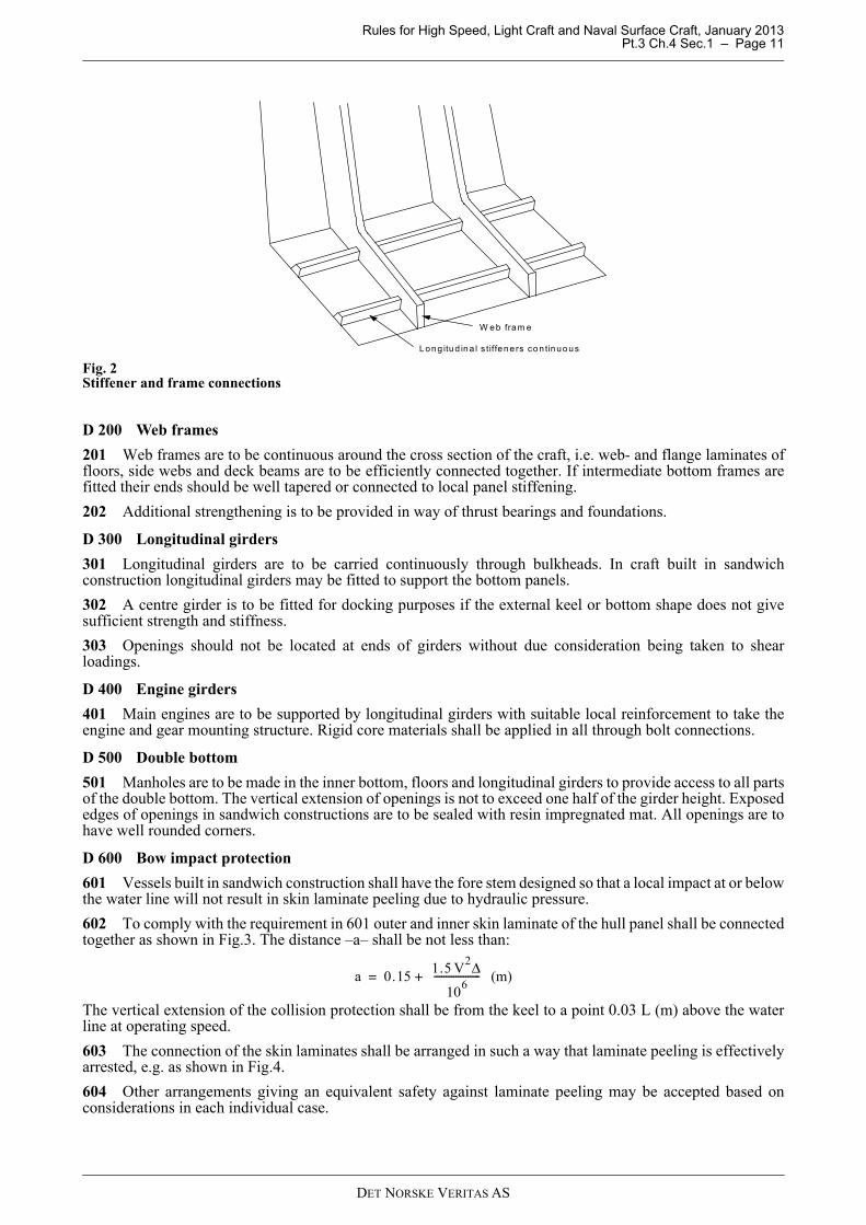
602 To comply with the requirement in 601 outer and inner skin laminate of the hull panel shall be connectedtogether as shown in Fig.3. The distance –a– shall be not less than:
The vertical extension of the collision protection shall be from the keel to a point 0.03 L (m) above the waterline at operating speed.
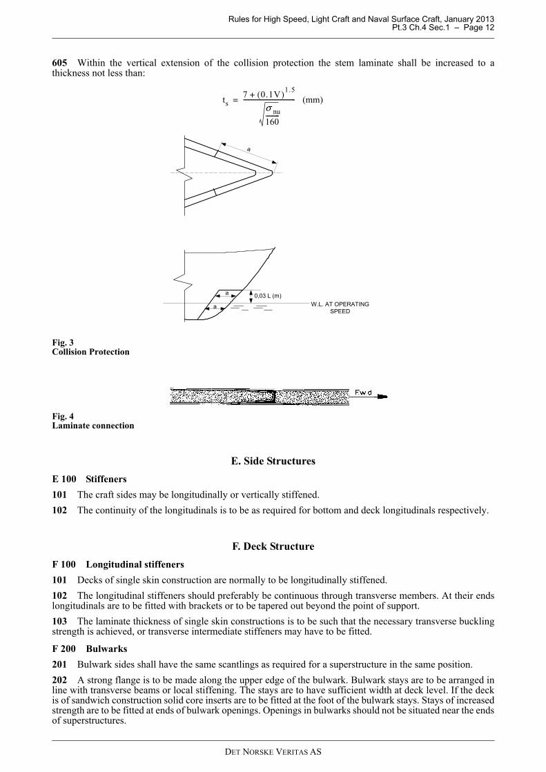
603 The connection of the skin laminates shall be arranged in such a way that laminate peeling is effectivelyarrested, e.g. as shown in Fig.4.
604 Other arrangements giving an equivalent safety against laminate peeling may be accepted based onconsiderations in each individual case.
W eb fram e
Long itud ina l s tiffene rs con tinuous
a 0.151.5 V
2Δ
106
------------------- (m)+=
DET NORSKE VERITAS AS
Rules for High Speed, Light Craft and Naval Surface Craft, January 2013 Pt.3 Ch.4 Sec.1 – Page 12
605 Within the vertical extension of the collision protection the stem laminate shall be increased to athickness not less than:
Fig. 3Collision Protection
Fig. 4Laminate connection
E. Side Structures
E 100 Stiffeners
101 The craft sides may be longitudinally or vertically stiffened.
102 The continuity of the longitudinals is to be as required for bottom and deck longitudinals respectively.
F. Deck Structure
F 100 Longitudinal stiffeners
101 Decks of single skin construction are normally to be longitudinally stiffened.
102 The longitudinal stiffeners should preferably be continuous through transverse members. At their endslongitudinals are to be fitted with brackets or to be tapered out beyond the point of support.
103 The laminate thickness of single skin constructions is to be such that the necessary transverse bucklingstrength is achieved, or transverse intermediate stiffeners may have to be fitted.
F 200 Bulwarks
201 Bulwark sides shall have the same scantlings as required for a superstructure in the same position.
202 A strong flange is to be made along the upper edge of the bulwark. Bulwark stays are to be arranged inline with transverse beams or local stiffening. The stays are to have sufficient width at deck level. If the deckis of sandwich construction solid core inserts are to be fitted at the foot of the bulwark stays. Stays of increasedstrength are to be fitted at ends of bulwark openings. Openings in bulwarks should not be situated near the endsof superstructures.
ts7 0.1V( )1.5
+
σ nu
160---------
---------------------------------- (mm)=
a
a
a
0,03 L (m)
W.L. AT OPERATINGSPEED
DET NORSKE VERITAS AS
Rules for High Speed, Light Craft and Naval Surface Craft, January 2013 Pt.3 Ch.4 Sec.1 – Page 13
203 Where bulwarks on exposed decks form wells, ample provision is to be made to facilitate freeing thedecks from water.
G. Bulkhead Structures
G 100 Watertight bulkheads
101 The number and location of transverse watertight bulkheads are to be in accordance with therequirements given in Ch.1 Sec.1 B.
G 200 Supporting bulkheads
201 Bulkheads supporting decks are to be regarded as pillars. The buckling strength will be considered ineach individual case.
H. Superstructures and Deckhouses
H 100 Definitions
101 Superstructure is defined as a decked structure on the freeboard deck, extending from side to side of theship or with the side plating not inboard of the shell plating more than 4% of the breadth (B).
102 Deckhouse is defined as a decked structure above the strength deck with the side plating being inboardof the shell plating more than 4% of the breadth (B).Long deckhouse – deckhouse having more than 0.2 L, of its length within 0.4 L amidship.Short deckhouse – deckhouse not defined as a long deckhouse.
H 200 Structural continuity
201 In superstructures and deckhouses, the front bulkhead is to be in line with a transverse bulkhead in thehull below or be supported by a combination of girders and pillars. The after end bulkhead is also to beeffectively supported. As far as practicable, exposed sides and internal longitudinal and transverse bulkheadsare to be located above girders and frames in the hull structure and are to be in line in the various tiers ofaccommodation. Where such structural arrangement in line is not possible, there is to be other effective support.
202 Sufficient transverse strength is to be provided by means of transverse bulkheads or girder structures.
203 At the break of superstructures, which have not set-in from the ship’s side, the side plating is to extendbeyond the ends of the superstructure, and is to be gradually reduced in height down to the deck or bulwark.The transition is to be smooth and without local discontinuities.
204 In long deckhouses, openings in the sides are to have well rounded corners. In deckhouses of single skinconstruction horizontal stiffeners are to be fitted along the upper and lower edge of large openings for windows.Openings for doors in the sides are to be substantially stiffened along the edges.
205 Casings supporting one or more decks above are to be adequately strengthened.
DET NORSKE VERITAS AS
Rules for High Speed, Light Craft and Naval Surface Craft, January 2013 Pt.3 Ch.4 Sec.2 – Page 14
SECTION 2 MANUFACTURING
A. General Requirements
A 100 Introduction
101 In this Section requirements related to the manufacturing, quality assurance and quality control of FRPstructures are given. It is to be recognised by the yard that there are limited or no means for non-destructiveexamination of FRP structures available. The yard is therefore to recognise the importance of exercising arigorous control of all steps of the fabrication to ascertain that the finished product complies with itsspecification(s).
102 The use of fabricating procedures differing from those specified in this Section will be subject to specialconsideration.
B. Storage of Raw Materials
B 100 Storage
101 Storage premises are to be so equipped and arranged that the material supplier’s directions for storageand handling of the raw materials can be followed.
102 Storage premises for reinforcement materials are to be kept dry and clean so that the raw material is notcontaminated. The materials shall be stored in unbroken original packaging before being used. Materials onwhich the original packaging has been broken shall be adequately protected against contamination when storedagain after use.
103 Reinforcement materials shall normally be stored at the same temperature and humidity as the workshopin which they are going to be used. If the storage temperature is not the same the material shall be acclimatisedat the workshop temperature and humidity prior to being deployed. The time of acclimatisation shall beadequate for the amount of reinforcement: for unbroken packages the acclimatisation shall have duration of atleast two days.
104 Resins, gelcoat, hardeners, additives etc. shall be stored according to the manufacturersrecommendations as regards temperature, shelf life etc. Raw materials which are stored at temperatures lowerthan + 18°C shall be acclimatised to the temperature of the workshop prior to being used. Tanks for resins etc.are to be handled during storage according to the manufacturers recommendations and equipped and arrangedaccordingly.
105 Core materials are to be stored dry and protected against contamination and mechanical damage. Corematerials shall normally be stored at the same temperature as the workshop in which they are going to be used.If the storage temperature is not the same the material shall be acclimatised for at the workshop temperatureand humidity prior to being deployed.
106 Core materials shall be stored in such a way that out-gassing of the material is ensured prior to beingused. Outgassing shall be carried out according to the manufacturers recommendations. When new freesurfaces is created in the material, e.g. by sanding, cutting or machining, proper outgassing shall be ensuredagain.
107 Pre-pregs shall be stored according to the manufacturer's recommendation. For pre-pregs stored inrefrigerated conditions a log shall be carried for each package showing the time and at which temperature thepackage has been stored/used outside its normal storage conditions.
B 200 Manufacturing premises and conditions
201 Manufacturing premises are to be so equipped and arranged that the material supplier’s directions forhandling the materials, the laminating process and curing conditions can be followed.
202 The manufacturing premises shall be free from dust and other contamination that may in any way impairthe quality of the end product.
203 The air temperature in the moulding shops is not to be less than +18°C. The stipulated minimumtemperature is to be attained at least 24 hours before commencement of lamination, and is to be maintainableregardless of the outdoor air temperature. The temperature in the moulding shop is not to vary more than ± 5°C. This limit can be exceeded provided ithas no detrimental effect on the product and provided there is no risk for condensation of humidity.
DET NORSKE VERITAS AS
Rules for High Speed, Light Craft and Naval Surface Craft, January 2013 Pt.3 Ch.4 Sec.2 – Page 15
204 The relative humidity of the air is to be kept so constant that condensation is avoided and is not to exceed80%. A higher relative humidity can be accepted on a case by case basis provided an adequate margin againstthe risk for condensation of humidity is provided.In areas where spray moulding is taking place, the air humidity is not to be less than 40%. The stipulated airhumidity is to be maintainable regardless of outdoor air temperature and humidity.More stringent requirements to humidity shall be adhered to if recommended by the manufacturer.
205 Other manufacturing conditions may be accepted based on special agreement with the Society providedthat condensation of humidity can be safely avoided.
206 Air temperature and relative humidity are to be recorded regularly and the records filed for a period ofat least two years. In larger shops there is to be at least one thermohydrograph for each 1500 m2 wherelamination is carried out. The location of the instruments shall be such as to give representative measurementresults.
207 Draught through doors, windows etc. and direct sunlight is not acceptable in places where lamination andcuring are in progress.
208 The ventilation plant is to be so arranged that the curing process is not negatively affected.
209 Sufficient scaffoldings are to be arranged so that all lamination work can be carried out without operatorsstanding on the core or on surfaces on which lamination work is taking place.
210 During lamination of larger constructions the temperature should be recorded at least at two levelsvertically in the workshop and the curing system should be adjusted to compensate for possible temperaturedifferences.
211 Prefabrication of panels and other components is to be carried out on tables, fixtures etc. above the shopfloor level. No fabrication shall be carried out on the shop floor.
C. Production Procedures and Workmanship
C 100 General requirements
101 Raw materials for all structural members covered by the Rules are to be of approved type in accordancewith Sec.4. The supplier’s directions for application of the materials are to be followed.
102 Specified procedures shall be implemented for all tasks with significance to the quality of the endproduct. Where necessary to exercise a satisfactory control of the quality, these procedures shall be documentedin writing in controlled documents.
103 The reference direction of reinforcement shall after being laid not deviate from the specified by morethan ± 5°.
104 Adjacent sheets of reinforcement shall in the normal case overlap to give structural continuity. Theoverlap length shall be such that the shear capacity of the overlap is not smaller than the tensile strength(perpendicular to the overlap) of the overlapping plies. The shear strength of the matrix shall not be assumedlarger than 8 MPa. A higher shear strength can be assumed subject to the approval of the Society. (E.g. for a 0/90° 1 000 g/m2 type glass reinforcement the overlap shall not be smaller than 30 mm.) In areas of lowutilisation, overlaps may be dispensed with subject to the approval of the Society. Overlaps shall be staggeredthrough the thickness of the laminate. The distance between two overlaps in adjacent plies shall not be smallerthan 100 mm.
105 Thickness changes in a laminate should be tapered over a minimum distance equal to 10 times thedifference in thickness.
106 Thickness changes in core materials should be tapered over a minimum distance equal to 2 times thedifference in thickness. A larger distance may be required to maintain structural continuity of the skins.
C 200 Sandwich lay-up
201 Sandwich constructions can be fabricated either by lamination on the core, application of the core againsta wet laminate, by bonding the core against a cured skin laminate using a core adhesive, by resin transfer, orby resin transfer moulding of the core together with one or both of the skin laminates.
202 An efficient bond is to be obtained between the skin laminates and the core and between the individualcore elements. The bond strength shall not be smaller than the tensile and shear strength of the core. Theapplication of a light CSM between core and skin laminate may be advantageous in this respect.
203 Approved tools for cutting, grinding etc. of various types of core material shall be specified in theproduction procedure.
DET NORSKE VERITAS AS

Rules for High Speed, Light Craft and Naval Surface Craft, January 2013 Pt.3 Ch.4 Sec.2 – Page 16
204 All joints between skin laminates and core and between the individual core elements are to be completelyfilled with resin, adhesive or filler material. The joint gap between core blocks should generally not be largerthan 3 mm. Larger gaps may be accepted if necessary, based on the characteristics of the adhesive or filler (e.g.its viscosity) and the thickness of the core. For slamming exposed areas a larger gap width should also bereflected in the qualification testing of the core material and the adhesive, i.e. during slamming testing, c.f. Pt.2Ch.4 and DNV Type Approval Program for core materials.
205 Core materials with open cells in the surface, should normally be impregnated with resin before it isapplied to a wet laminate or before lamination on the core is commenced.
206 When the core is applied manually to a wet laminate the surface shall be reinforced with a chopped strandmat of 450 g/m2 in plane surface and 600 g/m2 in curved surfaces.If vacuum is applied for core bonding the surface mats may be dispensed with provided it is demonstrated inthe qualification tests that an efficient bond between core and skin laminate is obtained.
207 If the core is built up by two or more layers of core and any form of resin transfer is used, arrangementsshall be made to ensure proper resin transfer and filling between the core blocks. This should be achieved byscoring or holing the core blocks and by placing a reinforcement fabric between the core blocks to facilitateresin distribution.
208 Frameworks for core build up shall give the core sufficient support to ensure stable geometrical shape ofthe construction and a rigid basis for the lamination work.
209 When a prefabricated skin laminate is bonded to a sandwich core measures are to be taken to evacuateair from the surface between skin and core.
210 The core material is to be free from dust and other contamination before the skin laminates are appliedor core elements are glued together. The moisture content shall be sufficiently low not to have any adverseeffect on curing. The acceptable moisture content shall be specified by the manufacturer of the core material.
211 When vacuum-bagging or similar processes are used it shall be ensured that curing in the core adhesivehas not been initiated before vacuum is applied.
C 300 Manual lamination
301 The reinforcement material is to be applied in the sequence stated on the approved plan(s).
302 When the laminate is applied in a mould a chopped strand mat of max. 450 g/m2 is to be applied next tothe gelcoat. The mat can be dispensed with provided a satisfactory resistance against water can be ensured.
303 The resin is to be applied on each layer of reinforcement. Gas and air pockets are to be worked out of thelaminate before the next layer is applied. Rolling of the layers are to be made carefully, paying special attentionto sharp corners and transitions.The viscosity and gel-time of the resin shall be adequate to prevent drain-out of resin on vertical and inclinedsurfaces.The tools and methods used when working the laminate shall not damage the fibres.
304 The time interval between applications of each layer of reinforcement is to be within the limits specifiedby the resin supplier. For thicker laminates care is to be taken to ensure a time interval sufficiently large to avoidexcessive heat generation.
305 Curing systems are to be selected with due regard to the reactivity of the resin and in accordance withthe supplier’s recommendations. Heat release during curing is to be kept at a safe level in accordance with thematerial manufacturer’s recommendations. The quantity of curing agents is to be kept within the limitsspecified by the supplier.
306 After completion of lamination, polyester laminates are to cure for at least 48 hours at an air temperatureof minimum +18°C. Curing at a higher temperature and a shorter curing time may be accepted on the basis ofcontrol of the curing rate. For other types of resins curing shall be carried out according to the specified curecycle and according to the resin manufacturer’s recommendations.
C 400 Vacuum assisted resin transfer moulding (VARTM) and vacuum-bagging
401 Points of resin injection shall be located and opened and closed in a sequence such that complete fillingof the mould without any air being trapped is ensured.
402 The resin shall be formulated, based on the resin manufacturer’s recommendations, such that an adequateviscosity and gel-time is obtained to enable filling of the complete mould and such that the maximumtemperature during cure is kept within acceptable limits, e.g. with respect to the temperature sensitivity of corematerials.
DET NORSKE VERITAS AS
Rules for High Speed, Light Craft and Naval Surface Craft, January 2013 Pt.3 Ch.4 Sec.2 – Page 17
403 The pressure level (vacuum) in the mould shall be specified prior to infusion. The pressure shall beadequate to ensure adequate consolidation of the laminate and that the specified mechanical properties arereached and that the mould is properly filled. The pressure shall be maintained throughout the mould duringthe cure cycle of the laminate, at least past the point of maximum temperature in the laminate, and the specifiedhold time. The vacuum shall be monitored by the use of pressure gauges distributed throughout the mould suchthat a reliable indication of the pressure distribution is obtained. This means that pressure gauges shall beplaced far away from vacuum suction points. Adequate means to locate and repair leakage shall be deployed.
C 500 Spray moulding
501 The term spray moulding is understood to mean the simultaneous deposit of resin and fibreglassreinforcement. Manufacturers using this method are subject to special approval.
502 When approval of the spray moulding process is considered, special attention will be paid to productionarrangement, ventilation equipment, the manufacturer’s own quality control and other factors of significanceto the quality of the finished product.
503 Spray moulding of structural members is to be carried out only by specially approved operators.
504 The equipment used for spray moulding is to give an even and homogenous build up of the laminate.Any dosage devices are to ensure an even application of additives to the polyester resin. No fibres are to beshorter than 20 mm.
505 When spray moulding there is to be an even application over the entire surface. Regular rolling out ofthe sprayed-on layers is to be carried out. Next to the gelcoat rolling out is to be done for max. 1.5 mm thicknessof finished laminate thickness, subsequently for at least each 2.5 mm of finished laminate thickness. The rollingout is to be done thoroughly to ensure adequate compression and removal of gas and air pockets. Special careis to be taken at sharp transitions and corners.
C 600 Curing
601 Cure cycles shall be documented by temperature records.
602 For cure taking place at room temperature in the workshop the registrations made in the workshop aresufficient to document the cure cycle.
603 For cure at elevated temperature, fans with ample capacity shall be operated in the compartment in whichthe cure is carried out to ensure an even distribution of temperature. Continuous records of temperaturethroughout the complete cure cycle shall be provided. Recording points shall be distributed throughout out thelength, width and height of the cure compartment to the extent necessary to verify that the temperaturedistribution is even.
C 700 Secondary bonding
701 A secondary bonding is defined as any bond between two FRP structures which is made after one or bothof the individual structures has effectively cured.
702 The surface ply of a laminate subject to secondary bonding and the first ply of the bonding laminate isnormally to be of chopped strand mat. This mat can be dispensed with provided the necessary bond strength isreached.
703 Surfaces in way of secondary bonding are to be clean and free from dust and other forms ofcontamination.
704 Laminates on which secondary bonds are to be carried out shall have an adequate surface preparation,normally including grinding.
705 If «peel strips» are used in the bonding surface the required surface treatment may be dispensed with.
C 800 Adhesive Bonding
801 Adhesive bonds shall be carried out according to the same procedure(s) as on which the design andqualification testing has been based, ref. Sect. 8 and according to the recommendations from the manufacturerof the adhesive. Procedure(s) shall be submitted to the Society prior to commencement of the bonding work.The procedure(s) shall give clear requirements to all factors that can affect the quality of the bond. As aminimum the following shall be covered: working conditions, surface preparation, application, clamp-up,curing cycle etc.
DET NORSKE VERITAS AS
Rules for High Speed, Light Craft and Naval Surface Craft, January 2013 Pt.3 Ch.4 Sec.2 – Page 18
D. Quality Assurance and Quality Control
D 100 Quality assurance
101 The shipyard is to have implemented an efficient system for quality assurance to ensure that the finishedproduct meets the specified requirements. The person or department responsible for the quality assurance shallhave clearly established authority and responsibility and be independent of the production departments.
102 The system should be formalized through a quality handbook or similar document at least containing thefollowing main objects:
— organisation of all quality related activities— identification of key personnel and their responsibilities— procedures for documentation— qualification of personnel— manufacturing conditions including recording of temperature and humidity— receipt and storage of raw materials— working procedures and instructions— formulation of resins— lamination records— procedures for quality control and inspection or testing— repair procedures— defect acceptance criteria.
The quality handbook shall be made available to the surveyor.
D 200 Quality control
201 A written quality plan shall be established for the production of each hull and superstructure. The qualityplan is subject to approval of the surveyor prior to commencement of the production.
202 The quality plan shall address at least the following items:
— relevant specifications, rules, statutory requirements etc.— drawings— list of raw materials— procedures for handling of raw materials— manufacturing procedures and instructions— procedure for keeping and filing of lamination records— procedure for keeping and filing of cure logs:
temperature and vacuum (for VARTM)— procedures for quality control and inspection or testing— inspection points— witness points by the DNV surveyor— production testing of laminates, joints and panels in accordance with 300— procedures for corrective actions when deficiencies are identified.
The quality plan may contain copies of all the necessary documentation or may refer to documents in thequality handbook or other controlled documentation. The relevant drawings may e.g. be identified by a list ofdrawings.
D 300 Production testing
301 The purpose of production testing is to verify that a consistent level of quality is maintained throughoutproduction. (Requirements for testing for qualification of material properties to be used in design are givenSec.3).
302 The yard is to specify a production test plan, as part of the quality plan, which as a minimum is to addressthe following items:
— mechanical strength of sandwich skin laminates, single skin laminates, flanges (caps) of stringers andgirders
— bond strength between core and skin laminates in sandwich panels— mechanical strength of major attachments and joints— acceptance criteria.
DET NORSKE VERITAS AS
Rules for High Speed, Light Craft and Naval Surface Craft, January 2013 Pt.3 Ch.4 Sec.2 – Page 19
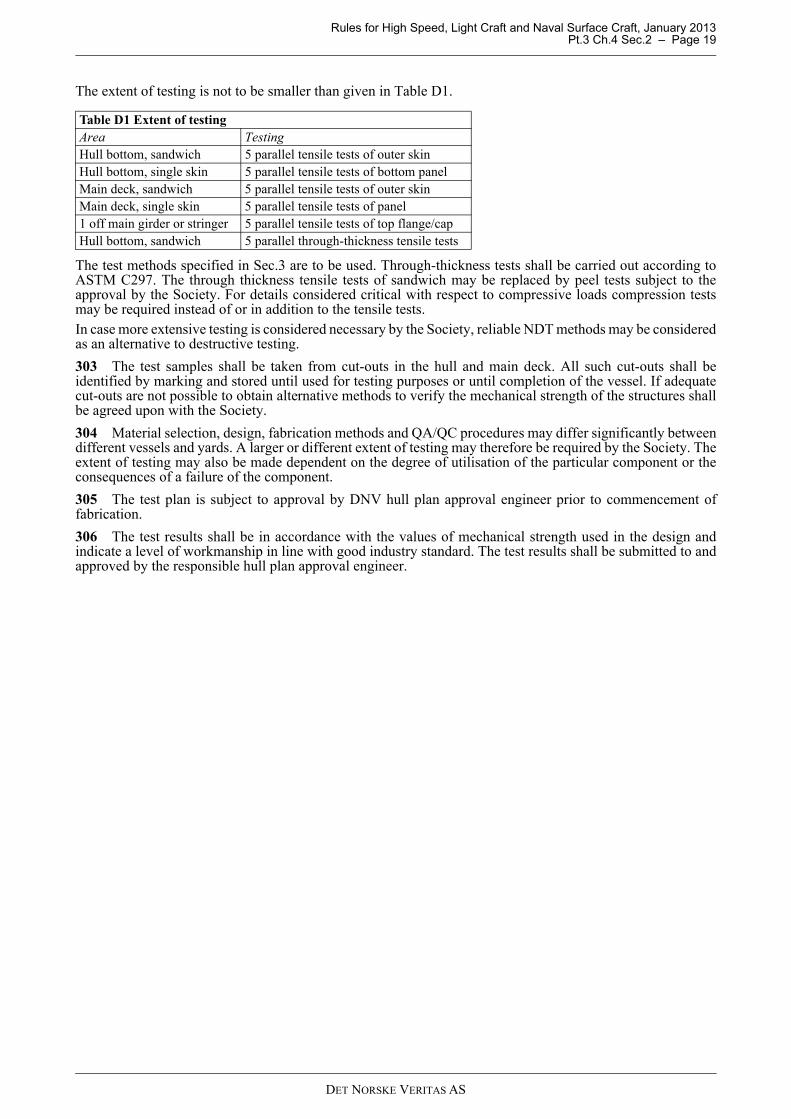
The extent of testing is not to be smaller than given in Table D1.
The test methods specified in Sec.3 are to be used. Through-thickness tests shall be carried out according toASTM C297. The through thickness tensile tests of sandwich may be replaced by peel tests subject to theapproval by the Society. For details considered critical with respect to compressive loads compression testsmay be required instead of or in addition to the tensile tests.In case more extensive testing is considered necessary by the Society, reliable NDT methods may be consideredas an alternative to destructive testing.
303 The test samples shall be taken from cut-outs in the hull and main deck. All such cut-outs shall beidentified by marking and stored until used for testing purposes or until completion of the vessel. If adequatecut-outs are not possible to obtain alternative methods to verify the mechanical strength of the structures shallbe agreed upon with the Society.
304 Material selection, design, fabrication methods and QA/QC procedures may differ significantly betweendifferent vessels and yards. A larger or different extent of testing may therefore be required by the Society. Theextent of testing may also be made dependent on the degree of utilisation of the particular component or theconsequences of a failure of the component.
305 The test plan is subject to approval by DNV hull plan approval engineer prior to commencement offabrication.
306 The test results shall be in accordance with the values of mechanical strength used in the design andindicate a level of workmanship in line with good industry standard. The test results shall be submitted to andapproved by the responsible hull plan approval engineer.
Table D1 Extent of testingArea TestingHull bottom, sandwich 5 parallel tensile tests of outer skin Hull bottom, single skin 5 parallel tensile tests of bottom panel Main deck, sandwich 5 parallel tensile tests of outer skin Main deck, single skin 5 parallel tensile tests of panel 1 off main girder or stringer 5 parallel tensile tests of top flange/cap Hull bottom, sandwich 5 parallel through-thickness tensile tests
DET NORSKE VERITAS AS
Rules for High Speed, Light Craft and Naval Surface Craft, January 2013 Pt.3 Ch.4 Sec.3 – Page 20
SECTION 3 MATERIALS
A. General
A 100 Introduction
101 In this Section requirements regarding the application of the various structural materials as well asmaterial protection and material testing are given.
A 200 Material certificates
201 Reinforcement, matrix, fillers and core materials for major hull structural elements are normally to bedelivered with DNV product certificate or be type approved by DNV.
202 Adhesives used for bonded joints shall be type approved by DNV.
B. Application of Materials
B 100 Hull and superstructure
101 The resin in hull and superstructure may be polyester, vinylester or epoxy. Other types of resins may beaccepted based on special consideration.
102 When using polyester, Grade 1 polyester is to be used for the hull shell laminate in single skinconstructions and for the outer hull skin laminate in sandwich construction. For the inner skin laminate andsuperstructure Grade 2 polyester may be accepted. Specifications for Grade 1 and Grade 2 resins are given inPt.2 Ch.4.
103 The outer reinforcement ply of the hull laminate (outer skin on sandwich panels) shall provide anadequate barrier against the penetration or absorption of water in the laminate. This also applies for areas insidethe hull expected to be continuously exposed to water submersion (i.e. bilge wells, etc.).
B 200 Tanks for storage of liquids
201 The inside coating layer of tanks shall provide an adequate barrier against the penetration or absorptionof fluids in the laminate.
202 The surface lining is as far as practicable to be laid continuously in the tanks side and bottom.
B 300 Surface coating
301 The underwater part of the hull, the inside of tanks for liquids and other areas exposed to permanentliquid submergence are to have an efficient surface coating, such as gelcoat, topcoat or an epoxy based painting,of sufficient thickness.
302 Other weather exposed surfaces are to have a suitable surface coating.
303 For inspection purposes the surface coating internally in the hull bottom is wherever feasible to beunpigmented.Where pigments are used, light colours should be used to expose damage and cracks more readily.
C. Material Properties and Qualification Testing
C 100 Basis for strength calculations
101 The design of the vessel is to be based on mechanical properties that are representative for the rawmaterials, production method(s), workshop conditions, lay-up sequence etc. that are used. The mechanicalproperties are to be based on mechanical qualification tests carried out on representative samples. For wellknown materials and production methods the mechanical properties may be based on standard engineeringanalytical methods, such as micro mechanics, laminate theory etc., substantiated by a reduced amount ofqualification testing.
102 The qualification testing is normally to be carried out and approved by the Society prior to carrying outthe design of the vessel. The yard shall submit a plan for qualification testing for approval by the Society priorto hull plans being approved. The plan for testing may invoke results from previous representative and welldocumented testing. The test methods specified in 200 shall be used.
DET NORSKE VERITAS AS
Rules for High Speed, Light Craft and Naval Surface Craft, January 2013 Pt.3 Ch.4 Sec.3 – Page 21
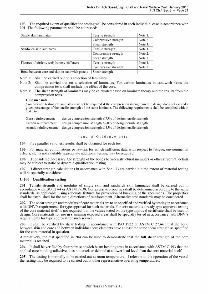
103 The required extent of qualification testing will be considered in each individual case in accordance with101. The following parameters shall be addressed:
Note 1: Shall be carried out on a selection of laminates.Note 2: Shall be carried out on a selection of laminates. For carbon laminates in sandwich skins the
compression tests shall include the effect of the core.Note 3: The shear strength of laminates may be calculated based on laminate theory and the results from the
compression tests.Guidance note:Compression testing of laminates may not be required if the compression strength used in design does not exceed agiven percentage of the tensile strength of the same laminate. The following requirements shall be complied with inthat case:
---e-n-d---of---G-u-i-d-a-n-c-e---n-o-t-e---
104 Five parallel valid test results shall be obtained for each test.
105 For material combinations or lay-ups for which sufficient data with respect to fatigue, environmentaleffects, etc. is not available appropriate additional testing may be required.
106 If considered necessary, the strength of the bonds between structural members or other structural detailsmay be subject to static or dynamic qualification testing.
107 If direct strength calculations in accordance with Sec.1 B are carried out the extent of material testingwill be specially considered.
C 200 Qualification testing
201 Tensile strength and modulus of single skin and sandwich skin laminates shall be carried out inaccordance with ISO 527-4 or ASTM D638. Compressive properties shall be determined according to the samestandards, as applicable, using adequate fixtures for prevention of buckling of the specimens. The propertiesshall be established for the main directions of reinforcement. Alternative test standards may be considered.
202 The shear strength and modulus of core materials are to be specified and verified by testing in accordancewith DNV’s requirements for type approval for such materials. For core materials already type approved testingof the core material itself is not required, but the values stated on the type approval certificate shall be used indesign. Core materials for use in slamming exposed areas shall be specially tested in accordance with DNV’srequirements for type approval for such service.
203 It shall be verified by shear testing in accordance with ISO 1922 or ASTM C 273-61 that the bondbetween skin and core and between individual core elements have at least the same shear strength as specifiedfor the core material in question.Alternatively, the test specified in 204 can be used to demonstrate that the full shear strength of the corematerial is reached.
204 It shall be verified by four point sandwich beam bending tests in accordance with ASTM C 393 that theapplied core bonding adhesive does not crack or debond at a lower load level than the core material itself.
205 The testing is normally to be carried out at room temperature. If relevant to the operation of the vesselthe testing may be required to be carried out at other representative operating temperatures.
Single skin laminates Tensile strength Note 1.Compressive strength Note 2.Shear strength Note 3.
Sandwich skin laminates Tensile strength Note 1.Compressive strength Note 2.Shear strength Note 3.
Flanges of girders, web frames, stiffeners Tensile strength Note 1.Compressive strength Note 2.
Bond between core and skin in sandwich panels Shear strength
Glass reinforcement: design compression strength ≤ 75% of design tensile strengthCarbon reinforcement: design compression strength ≤ 60% of design tensile strengthAramid reinforcement: design compression strength ≤ 45% of design tensile strength
DET NORSKE VERITAS AS

Rules for High Speed, Light Craft and Naval Surface Craft, January 2013 Pt.3 Ch.4 Sec.4 – Page 22
SECTION 4 HULL GIRDER STRENGTH
A. General
A 100 Introduction
101 In this section requirements to longitudinal and transverse hull girder strength is given. In addition,buckling control may be required.
102 Longitudinal strength has generally to be checked for the craft types and sizes mentioned in theintroduction to Ch.1 Sec.3, «Hull Girder Loads».
103 For new designs (prototypes) of large and structurally complicated craft (f.i. multi-hull types) a complete3-dimensional global analysis of the transverse strength, in combination with longitudinal stresses, is to becarried out.
104 Buckling strength in bottom and deck may, however, have to be checked also for the other craft. For thispurpose formulae for estimate of section modulus to deck and bottom based on bottom and deck cross-sectionalareas have been given in Ch.1 Sec.3 A700.
105 When calculating the section modulus of a composite structure possible differences in the E-modulus ofvarious structural members are to be taken into account.The stresses are to be corrected accordingly.
A 200 Definitions
201 Moulded deck line, Rounded sheer strake, Sheer strake and Stringer plate are as defined in Fig.1.
Fig. 1Deck corners
B. Vertical Bending Strength
B 100 Hull section modulus requirement
101
M = the longitudinal midship bending moment in kNm from Ch.1 Sec.3.= MH for monohulls, catamarans and side wall craft in crest and hollow landing condition= max. total moment for hydrofoil on foils= max. still water + wave bending moment for hydrofoils and air cushion vehicles and some other craft in
the slowed-down condition= max. still water + wave bending moment for high speed displacement craft and semi-planing craft
in the displacement mode.σ = 0.3 σ nu N/mm2 in general.
= 0.27 σ nu N/mm2 for hydrofoil on foils.= 0.24 σ nu N/mm2 in slowed-down condition for planing craft.
ZMσ----- .10
3cm
3( )=
V L 5<⁄( )
DET NORSKE VERITAS AS
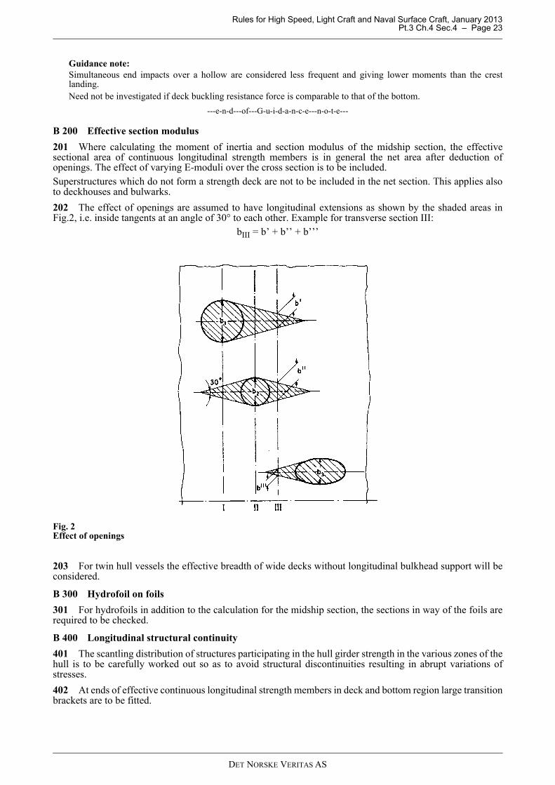
Rules for High Speed, Light Craft and Naval Surface Craft, January 2013 Pt.3 Ch.4 Sec.4 – Page 23
Guidance note:Simultaneous end impacts over a hollow are considered less frequent and giving lower moments than the crestlanding.Need not be investigated if deck buckling resistance force is comparable to that of the bottom.
---e-n-d---of---G-u-i-d-a-n-c-e---n-o-t-e---
B 200 Effective section modulus
201 Where calculating the moment of inertia and section modulus of the midship section, the effectivesectional area of continuous longitudinal strength members is in general the net area after deduction ofopenings. The effect of varying E-moduli over the cross section is to be included.Superstructures which do not form a strength deck are not to be included in the net section. This applies alsoto deckhouses and bulwarks.
202 The effect of openings are assumed to have longitudinal extensions as shown by the shaded areas inFig.2, i.e. inside tangents at an angle of 30° to each other. Example for transverse section III:
bIII = b’ + b’’ + b’’’
Fig. 2Effect of openings
203 For twin hull vessels the effective breadth of wide decks without longitudinal bulkhead support will beconsidered.
B 300 Hydrofoil on foils
301 For hydrofoils in addition to the calculation for the midship section, the sections in way of the foils arerequired to be checked.
B 400 Longitudinal structural continuity
401 The scantling distribution of structures participating in the hull girder strength in the various zones of thehull is to be carefully worked out so as to avoid structural discontinuities resulting in abrupt variations ofstresses.
402 At ends of effective continuous longitudinal strength members in deck and bottom region large transitionbrackets are to be fitted.
DET NORSKE VERITAS AS
Rules for High Speed, Light Craft and Naval Surface Craft, January 2013 Pt.3 Ch.4 Sec.4 – Page 24
B 500 Openings
501 A keel laminate for docking is normally not to have openings. In the bilge laminate, within 0.5 Lamidships, openings are to be avoided as far as practicable. Any necessary openings in the bilge laminate areto be kept clear of a bilge keel.
502 Openings in strength deck are as far as practicable to be located well clear of ship’s side and hatchcorners.
503 Openings in strength members should generally have an elliptical form. Larger openings in deck may beaccepted with well rounded corners and are to be situated as near to the craft’s centreline as practicable.
504 For corners with rounded shape the radius is not to be less than: r = 0.025 Bdk (m)
Bdk = breadth of strength deck.
r need not be taken greater than 0.1 b (m) where b = breadth of opening in m. For local reinforcement of deckplating at circular corners, see Sec.5 B.
505 Edges of openings are to be smooth. Small holes are to be drilled.
C. Shear Strength
C 100 Cases to be investigated
101 If doors are arranged in the ship’s side, the required sectional area of the remaining side panel will bespecially considered.
102 If rows of windows are arranged below strength deck, sufficient horizontal shear area must be arrangedto carry down the midship tension.
D. Cases to be investigated
D 100 Inertia induced loads
101 Especially transversely framed parts of forebody may need a check for the axial inertia force given inCh.1 Sec.3 A700.
al = max. surge acceleration, not to be taken less than:
The height distribution of stresses will depend on instantaneous forward immersion and on height location ofcargo.
102 Bottom structure in way of thrust bearings may need a check for the increased thrust when vessel isretarded by a crest in front.
103 Allowable axial stress and associated shear stresses will be related to the stresses already existing in theregion.
E. Transverse Strength of Twin Hull Craft
E 100 Transverse strength
101 The twin hull connecting structure is to have adequate transverse strength related to the design loads andmoments discussed in Ch.1.
102 When calculating the moment of inertia, and section moduli of the longitudinal section of the connectingstructure, the effective sectional area of transverse strength members is in general the net area with effectiveflange after deduction of openings.The effective shear area of transverse strength members is in general the net web area after deduction ofopenings.
FL Δ g0 al kN( )=
0.4 g for V
L------- 5≥
0.2 g for V
L------- 3≤
DET NORSKE VERITAS AS

Rules for High Speed, Light Craft and Naval Surface Craft, January 2013 Pt.3 Ch.4 Sec.4 – Page 25
E 200 Allowable stresses
201 If direct calculations using the full stiffness and strength properties of the laminate are carried outrequirements for the failure strength ratio, R, are given in Sec.1 Table C1.
202 When a simplified calculation method is used, the total normal stresses in the two main directions shallcomply with the requirements of Sec.5 and Sec.6.In plane laminate shear stresses shall be less than 0.25τ ult.
DET NORSKE VERITAS AS
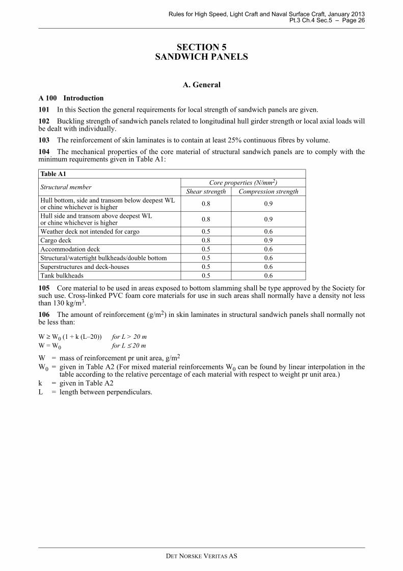
Rules for High Speed, Light Craft and Naval Surface Craft, January 2013 Pt.3 Ch.4 Sec.5 – Page 26
SECTION 5 SANDWICH PANELS
A. General
A 100 Introduction
101 In this Section the general requirements for local strength of sandwich panels are given.
102 Buckling strength of sandwich panels related to longitudinal hull girder strength or local axial loads willbe dealt with individually.
103 The reinforcement of skin laminates is to contain at least 25% continuous fibres by volume.
104 The mechanical properties of the core material of structural sandwich panels are to comply with theminimum requirements given in Table A1:
105 Core material to be used in areas exposed to bottom slamming shall be type approved by the Society forsuch use. Cross-linked PVC foam core materials for use in such areas shall normally have a density not lessthan 130 kg/m3.
106 The amount of reinforcement (g/m2) in skin laminates in structural sandwich panels shall normally notbe less than:
W = mass of reinforcement pr unit area, g/m2
W0 = given in Table A2 (For mixed material reinforcements W0 can be found by linear interpolation in thetable according to the relative percentage of each material with respect to weight pr unit area.)
k = given in Table A2L = length between perpendiculars.
Table A1
Structural memberCore properties (N/mm2)
Shear strength Compression strengthHull bottom, side and transom below deepest WL or chine whichever is higher 0.8 0.9
Hull side and transom above deepest WL or chine whichever is higher 0.8 0.9
Weather deck not intended for cargo 0.5 0.6Cargo deck 0.8 0.9Accommodation deck 0.5 0.6Structural/watertight bulkheads/double bottom 0.5 0.6Superstructures and deck-houses 0.5 0.6Tank bulkheads 0.5 0.6
W ≥ W0 (1 + k (L–20)) for L > 20 mW = W0 for L ≤ 20 m
DET NORSKE VERITAS AS
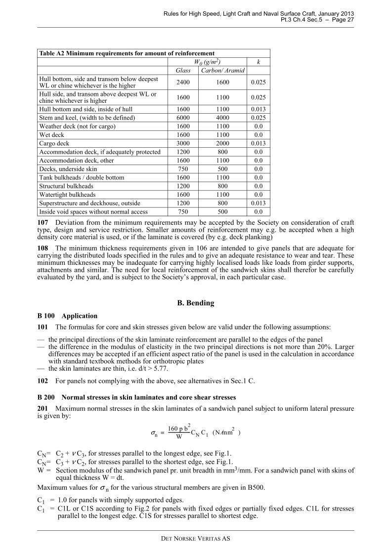
Rules for High Speed, Light Craft and Naval Surface Craft, January 2013 Pt.3 Ch.4 Sec.5 – Page 27
107 Deviation from the minimum requirements may be accepted by the Society on consideration of crafttype, design and service restriction. Smaller amounts of reinforcement may e.g. be accepted when a highdensity core material is used, or if the laminate is covered (by e.g. deck planking)
108 The minimum thickness requirements given in 106 are intended to give panels that are adequate forcarrying the distributed loads specified in the rules and to give an adequate resistance to wear and tear. Theseminimum thicknesses may be inadequate for carrying highly localised loads like loads from girder supports,attachments and similar. The need for local reinforcement of the sandwich skins shall therefor be carefullyevaluated by the yard, and is subject to the Society’s approval, in each particular case.
B. Bending
B 100 Application
101 The formulas for core and skin stresses given below are valid under the following assumptions:
— the principal directions of the skin laminate reinforcement are parallel to the edges of the panel— the difference in the modulus of elasticity in the two principal directions is not more than 20%. Larger
differences may be accepted if an efficient aspect ratio of the panel is used in the calculation in accordancewith standard textbook methods for orthotropic plates
— the skin laminates are thin, i.e. d/t > 5.77.
102 For panels not complying with the above, see alternatives in Sec.1 C.
B 200 Normal stresses in skin laminates and core shear stresses
201 Maximum normal stresses in the skin laminates of a sandwich panel subject to uniform lateral pressureis given by:
CN= C2 + ν C3, for stresses parallel to the longest edge, see Fig.1.CN= C3 + ν C2, for stresses parallel to the shortest edge, see Fig.1.W = Section modulus of the sandwich panel pr. unit breadth in mm3/mm. For a sandwich panel with skins of
equal thickness W = dt.Maximum values for σ n for the various structural members are given in B500.
C1 = 1.0 for panels with simply supported edges.C1 = C1L or C1S according to Fig.2 for panels with fixed edges or partially fixed edges. C1L for stresses
parallel to the longest edge. C1S for stresses parallel to shortest edge.
Table A2 Minimum requirements for amount of reinforcementW0 (g/m2) k
Glass Carbon/ AramidHull bottom, side and transom below deepest WL or chine whichever is the higher 2400 1600 0.025
Hull side, and transom above deepest WL or chine whichever is higher 1600 1100 0.025
Hull bottom and side, inside of hull 1600 1100 0.013Stem and keel, (width to be defined) 6000 4000 0.025Weather deck (not for cargo) 1600 1100 0.0Wet deck 1600 1100 0.0Cargo deck 3000 2000 0.013Accommodation deck, if adequately protected 1200 800 0.0Accommodation deck, other 1600 1100 0.0Decks, underside skin 750 500 0.0Tank bulkheads / double bottom 1600 1100 0.0Structural bulkheads 1200 800 0.0Watertight bulkheads 1600 1100 0.0Superstructure and deckhouse, outside 1200 800 0.013Inside void spaces without normal access 750 500 0.0
σn160 p b
2
W--------------------CN C1 N mm
2⁄( )=
DET NORSKE VERITAS AS
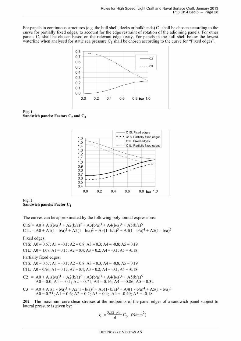
Rules for High Speed, Light Craft and Naval Surface Craft, January 2013 Pt.3 Ch.4 Sec.5 – Page 28
For panels in continuous structures (e.g. the hull shell, decks or bulkheads) C1 shall be chosen according to thecurve for partially fixed edges, to account for the edge restraint of rotation of the adjoining panels. For otherpanels C1 shall be chosen based on the relevant edge fixity. For panels in the hull shell below the lowestwaterline when analysed for static sea pressure C1 shall be chosen according to the curve for “Fixed edges”.
Fig. 1Sandwich panels: Factors C2 and C3
Fig. 2Sandwich panels: Factor C1
The curves can be approximated by the following polynomial expressions:
C1S = A0 + A1(b/a)1 + A2(b/a)2 + A3(b/a)3 + A4(b/a)4 + A5(b/a)5
C1L = A0 + A1(1 - b/a)1 + A2(1 - b/a)2 + A3(1- b/a)3 + A4(1 - b/a)4 + A5(1 - b/a)5
Fixed edges:C1S: A0 = 0.67; A1 = -0.1; A2 = 0.8; A3 = 0.3; A4 = -0.8; A5 = 0.19C1L: A0 = 1.07; A1 = 0.15; A2 = 0.4; A3 = 0.2; A4 = -0.1; A5 = -0.18
Partially fixed edges:C1S: A0 = 0.57; A1 = -0.1; A2 = 0.8; A3 = 0.3; A4 = -0.8; A5 = 0.19C1L: A0 = 0.96; A1 = 0.17; A2 = 0.4; A3 = 0.2; A4 = -0.1; A5 = -0.18
C2 = A0 + A1(b/a)1 + A2(b/a)2 + A3(b/a)3 + A4(b/a)4 + A5(b/a)5
A0 = 0.0; A1 = -0.1; A2 = 0.71; A3 = 0.16; A4 = -0.86; A5 = 0.32
C3 = A0 + A1(1 - b/a)1 + A2(1 - b/a)2 + A3(1- b/a)3 + A4(1 - b/a)4 + A5(1 - b/a)5
A0 = 0.23; A1 = 0.6; A2 = 0.2; A3 = 0.4; A4 = -0.49; A5 = -0.18
202 The maximum core shear stresses at the midpoints of the panel edges of a sandwich panel subject tolateral pressure is given by:
0.00.10.2
0.30.4
0.50.6
0.70.8
0.0 0.2 0.4 0.6 0.8 1.0b/a
C2
C3
0.40.50.60.70.80.91.01.11.21.31.41.51.6
0.0 0.2 0.4 0.6 0.8 1.0b/a
C1S. Fixed edges
C1S. Partially fixed edgesC1L. Fixed edges
C1L. Partially fixed edges
τc0.52 p b
d-------------------- CS (N/mm
2 )=
DET NORSKE VERITAS AS
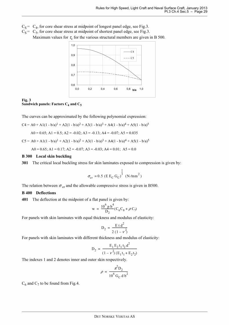
Rules for High Speed, Light Craft and Naval Surface Craft, January 2013 Pt.3 Ch.4 Sec.5 – Page 29
CS = C4, for core shear stress at midpoint of longest panel edge, see Fig.3.CS = C5, for core shear stress at midpoint of shortest panel edge, see Fig.3.
Maximum values for τc for the various structural members are given in B 500.
Fig. 3Sandwich panels: Factors C4 and C5
The curves can be approximated by the following polynomial expression:
B 300 Local skin buckling
301 The critical local buckling stress for skin laminates exposed to compression is given by:
The relation between σ cr and the allowable compressive stress is given in B500.
B 400 Deflections
401 The deflection at the midpoint of a flat panel is given by:
For panels with skin laminates with equal thickness and modulus of elasticity:
For panels with skin laminates with different thickness and modulus of elasticity:
The indexes 1 and 2 denotes inner and outer skin respectively.
C6 and C7 to be found from Fig.4.
C4 = A0 + A1(1 - b/a)1 + A2(1 - b/a)2 + A3(1 - b/a)3 + A4(1 - b/a)4 + A5(1 - b/a)5
A0 = 0.65; A1 = 0.5; A2 = -0.02; A3 = -0.13; A4 = -0.07; A5 = 0.035
C5 = A0 + A1(1 - b/a)1 + A2(1 - b/a)2 + A3(1 - b/a)3 + A4(1 - b/a)4 + A5(1 - b/a)5
A0 = 0.65; A1 = 0.17; A2 = -0.07; A3 = -0.03; A4 = 0.01; A5 = 0.0
0,6
0,7
0,8
0,9
1,0
0,0 0,2 0,4 0,6 0,8 1,0b/a
C4
C5
σcr 0.5 E EC GC( )13---
N mm2⁄( )=
w10
6p b
4
D2-------------------- C6C8 ρ C7+( )=
D2E t d
2
2 1 ν 2–( )
------------------------=
D2
E1 E2 t1 t2 d2
1 ν 2–( ) E1 t1 E2 t2+( )
------------------------------------------------------=
ρπ2
D2
106
GC d b2
-----------------------------=
DET NORSKE VERITAS AS
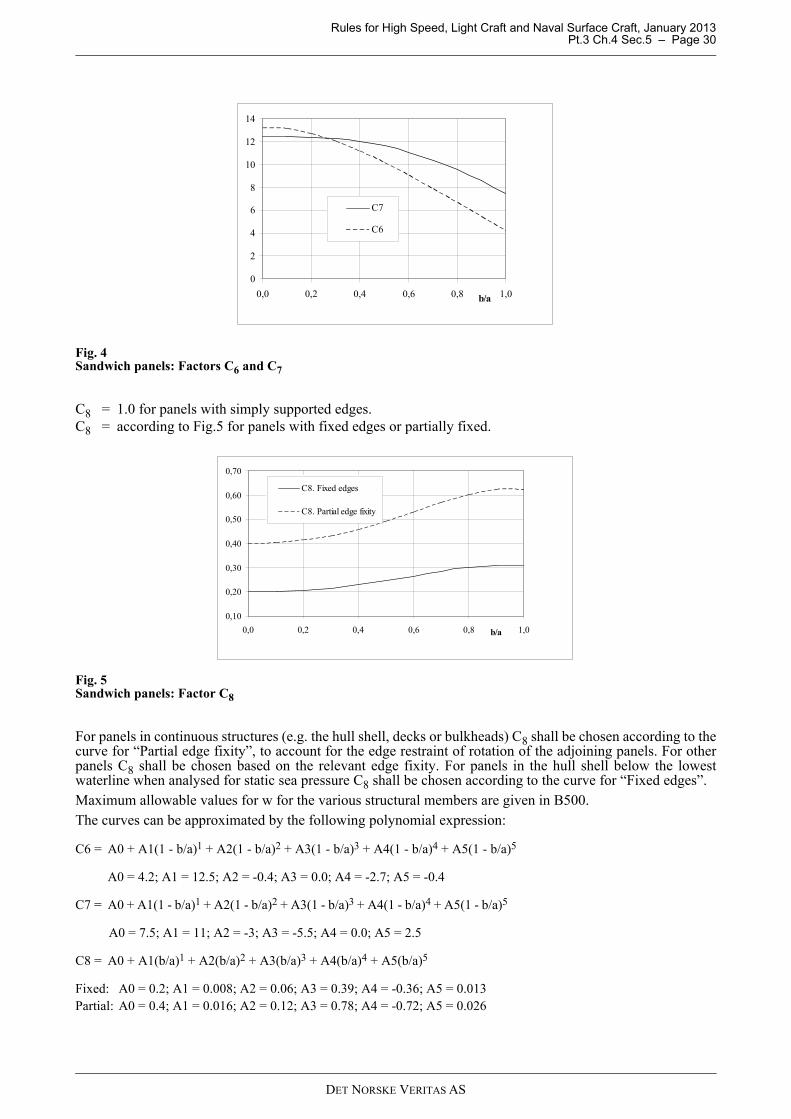
Rules for High Speed, Light Craft and Naval Surface Craft, January 2013 Pt.3 Ch.4 Sec.5 – Page 30
Fig. 4Sandwich panels: Factors C6 and C7
C8 = 1.0 for panels with simply supported edges.C8 = according to Fig.5 for panels with fixed edges or partially fixed.
Fig. 5Sandwich panels: Factor C8
For panels in continuous structures (e.g. the hull shell, decks or bulkheads) C8 shall be chosen according to thecurve for “Partial edge fixity”, to account for the edge restraint of rotation of the adjoining panels. For otherpanels C8 shall be chosen based on the relevant edge fixity. For panels in the hull shell below the lowestwaterline when analysed for static sea pressure C8 shall be chosen according to the curve for “Fixed edges”.Maximum allowable values for w for the various structural members are given in B500.The curves can be approximated by the following polynomial expression:
C6 = A0 + A1(1 - b/a)1 + A2(1 - b/a)2 + A3(1 - b/a)3 + A4(1 - b/a)4 + A5(1 - b/a)5
A0 = 4.2; A1 = 12.5; A2 = -0.4; A3 = 0.0; A4 = -2.7; A5 = -0.4
C7 = A0 + A1(1 - b/a)1 + A2(1 - b/a)2 + A3(1 - b/a)3 + A4(1 - b/a)4 + A5(1 - b/a)5
A0 = 7.5; A1 = 11; A2 = -3; A3 = -5.5; A4 = 0.0; A5 = 2.5
C8 = A0 + A1(b/a)1 + A2(b/a)2 + A3(b/a)3 + A4(b/a)4 + A5(b/a)5
Fixed: A0 = 0.2; A1 = 0.008; A2 = 0.06; A3 = 0.39; A4 = -0.36; A5 = 0.013Partial: A0 = 0.4; A1 = 0.016; A2 = 0.12; A3 = 0.78; A4 = -0.72; A5 = 0.026
0
2
4
6
8
10
12
14
0,0 0,2 0,4 0,6 0,8 1,0b/a
C7
C6
0,10
0,20
0,30
0,40
0,50
0,60
0,70
0,0 0,2 0,4 0,6 0,8 1,0b/a
C8. Fixed edges
C8. Partial edge fixity
DET NORSKE VERITAS AS
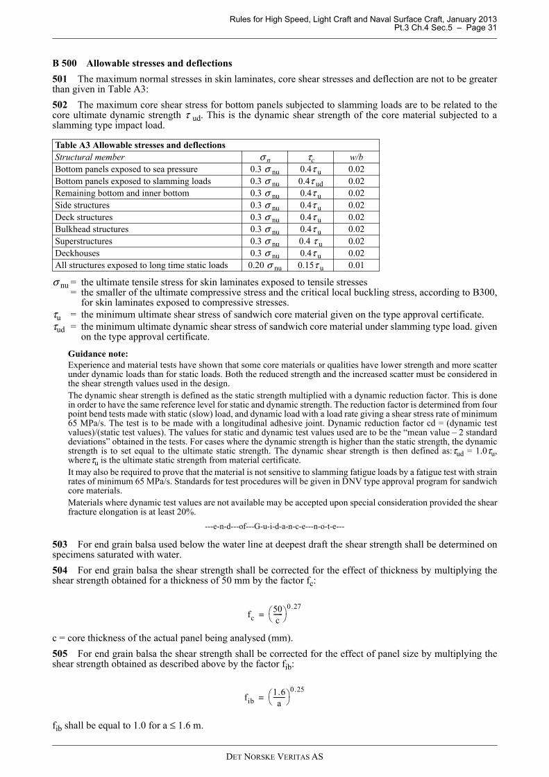
Rules for High Speed, Light Craft and Naval Surface Craft, January 2013 Pt.3 Ch.4 Sec.5 – Page 31
B 500 Allowable stresses and deflections
501 The maximum normal stresses in skin laminates, core shear stresses and deflection are not to be greaterthan given in Table A3:
502 The maximum core shear stress for bottom panels subjected to slamming loads are to be related to thecore ultimate dynamic strength τ ud. This is the dynamic shear strength of the core material subjected to aslamming type impact load.
σ nu = the ultimate tensile stress for skin laminates exposed to tensile stresses= the smaller of the ultimate compressive stress and the critical local buckling stress, according to B300,
for skin laminates exposed to compressive stresses.τu = the minimum ultimate shear stress of sandwich core material given on the type approval certificate.τud = the minimum ultimate dynamic shear stress of sandwich core material under slamming type load. given
on the type approval certificate.
Guidance note:Experience and material tests have shown that some core materials or qualities have lower strength and more scatterunder dynamic loads than for static loads. Both the reduced strength and the increased scatter must be considered inthe shear strength values used in the design.The dynamic shear strength is defined as the static strength multiplied with a dynamic reduction factor. This is donein order to have the same reference level for static and dynamic strength. The reduction factor is determined from fourpoint bend tests made with static (slow) load, and dynamic load with a load rate giving a shear stress rate of minimum65 MPa/s. The test is to be made with a longitudinal adhesive joint. Dynamic reduction factor cd = (dynamic testvalues)/(static test values). The values for static and dynamic test values used are to be the “mean value – 2 standarddeviations” obtained in the tests. For cases where the dynamic strength is higher than the static strength, the dynamicstrength is to set equal to the ultimate static strength. The dynamic shear strength is then defined as:τud = 1.0τu,whereτu is the ultimate static strength from material certificate.It may also be required to prove that the material is not sensitive to slamming fatigue loads by a fatigue test with strainrates of minimum 65 MPa/s. Standards for test procedures will be given in DNV type approval program for sandwichcore materials.Materials where dynamic test values are not available may be accepted upon special consideration provided the shearfracture elongation is at least 20%.
---e-n-d---of---G-u-i-d-a-n-c-e---n-o-t-e---
503 For end grain balsa used below the water line at deepest draft the shear strength shall be determined onspecimens saturated with water.
504 For end grain balsa the shear strength shall be corrected for the effect of thickness by multiplying theshear strength obtained for a thickness of 50 mm by the factor fc:
c = core thickness of the actual panel being analysed (mm).
505 For end grain balsa the shear strength shall be corrected for the effect of panel size by multiplying theshear strength obtained as described above by the factor fib:
fib shall be equal to 1.0 for a ≤ 1.6 m.
Table A3 Allowable stresses and deflectionsStructural member σ n τc w/bBottom panels exposed to sea pressure 0.3 σ nu 0.4τ u 0.02Bottom panels exposed to slamming loads 0.3 σ nu 0.4τ ud 0.02Remaining bottom and inner bottom 0.3 σ nu 0.4τ u 0.02Side structures 0.3 σ nu 0.4τ u 0.02Deck structures 0.3 σ nu 0.4τ u 0.02Bulkhead structures 0.3 σ nu 0.4τ u 0.02Superstructures 0.3 σ nu 0.4 τ u 0.02Deckhouses 0.3 σ nu 0.4τ u 0.02All structures exposed to long time static loads 0.20 σ nu 0.15τ u 0.01
fc50c
------ 0.27
=
fib1.6a
-------- 0.25
=
DET NORSKE VERITAS AS
Rules for High Speed, Light Craft and Naval Surface Craft, January 2013 Pt.3 Ch.4 Sec.6 – Page 32
SECTION 6 STIFFENED SINGLE SKIN CONSTRUCTION
A. General
A 100 Introduction
101 In this section the general requirements for local strength of stiffened single skin constructions are given.
102 Buckling strength of single skin panels subjected to longitudinal hull girder or local compression loadswill be dealt with individually.
A 200 Minimum requirements for structural single skin plates
201 The reinforcement of single skin laminates are to contain at least 25% continuous fibres by volume.
202 The thickness of single skin laminates fabricated from glass are in general not to be less than:W = W0 (1 + k (L – 20)) for L > 20 m
W = W0 for L ≤ 20 m
W = mass of reinforcement pr. unit area, g/m2
W0 = given in Table A1k = given in Table A1L = length between perpendiculars.
203 The minimum thickness of single skin laminates fabricated from other types of reinforcements aresubject to special consideration.
B. Laterally Loaded Single Skin Laminates
B 100 Assumptions
101 The formulae given below are valid under the following assumptions:
1) The principal directions of reinforcement are parallel to the edges of the panel.2) The difference in the modulus of elasticity in the two principal direction of reinforcement is not more than
20%.3) The load is uniformly distributed.
102 For laminates not complying with the above reference is made to Sec.1 C.
103 Laminates may be analysed disregarding the membrane effect according to the requirements given in 200and 300 or including the membrane effect according to the requirements given in 400 and 500.
Table A1 Minimum amount of reinforcementStructural member W0 (g/m2) kHull bottom, side and transom below deepest WL or chine whichever is higher 4200 0.025
Hull side and transom above deepest WL or chine whichever is higher 4200 0.025
Stem and keel to 0.01 L from centreline 7500 0.025Chine and transom corners to 0.01 L from chine edge 5800 0.025Bottom aft in way of rudder, shaft braces, and shaft penetrations 6600 0.025Weather deck not intended for cargo 4200 0.0Cargo deck 5400 0.013Accommodation deck 2900 0.0Structural/watertight bulkheads/double bottom 4200 0.0Tank bulkheads 4500 0.0Other bulkheads 2500 0.0Superstructures and deckhouses 4200 0.013
DET NORSKE VERITAS AS
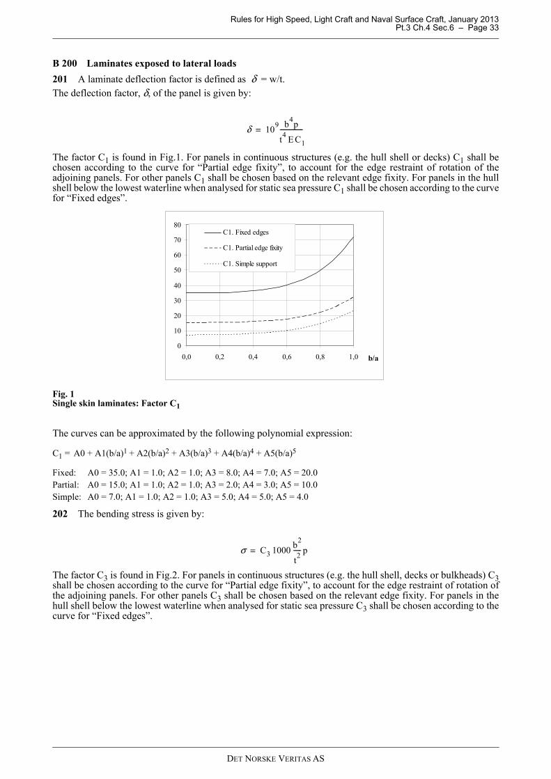
Rules for High Speed, Light Craft and Naval Surface Craft, January 2013 Pt.3 Ch.4 Sec.6 – Page 33
B 200 Laminates exposed to lateral loads
201 A laminate deflection factor is defined as δ = w/t. The deflection factor, δ, of the panel is given by:
The factor C1 is found in Fig.1. For panels in continuous structures (e.g. the hull shell or decks) C1 shall bechosen according to the curve for “Partial edge fixity”, to account for the edge restraint of rotation of theadjoining panels. For other panels C1 shall be chosen based on the relevant edge fixity. For panels in the hullshell below the lowest waterline when analysed for static sea pressure C1 shall be chosen according to the curvefor “Fixed edges”.
Fig. 1Single skin laminates: Factor C1
The curves can be approximated by the following polynomial expression:
202 The bending stress is given by:
The factor C3 is found in Fig.2. For panels in continuous structures (e.g. the hull shell, decks or bulkheads) C3shall be chosen according to the curve for “Partial edge fixity”, to account for the edge restraint of rotation ofthe adjoining panels. For other panels C3 shall be chosen based on the relevant edge fixity. For panels in thehull shell below the lowest waterline when analysed for static sea pressure C3 shall be chosen according to thecurve for “Fixed edges”.
C1 = A0 + A1(b/a)1 + A2(b/a)2 + A3(b/a)3 + A4(b/a)4 + A5(b/a)5
Fixed: A0 = 35.0; A1 = 1.0; A2 = 1.0; A3 = 8.0; A4 = 7.0; A5 = 20.0Partial: A0 = 15.0; A1 = 1.0; A2 = 1.0; A3 = 2.0; A4 = 3.0; A5 = 10.0Simple: A0 = 7.0; A1 = 1.0; A2 = 1.0; A3 = 5.0; A4 = 5.0; A5 = 4.0
δ 109 b
4p
t4
E C1
---------------=
0
10
20
30
40
50
60
70
80
0,0 0,2 0,4 0,6 0,8 1,0 b/a
C1. Fixed edges
C1. Partial edge fixity
C1. Simple support
σ C3 1000b
2
t2
----- p=
DET NORSKE VERITAS AS

Rules for High Speed, Light Craft and Naval Surface Craft, January 2013 Pt.3 Ch.4 Sec.6 – Page 34
Fig. 2Single skin laminates: Factor C3
B 300 Allowable stresses and deflections (when excluding membrane effects)
301 The maximum values for δ is 2.0. For a panel for which its deflection will not interfere with other partsof the structure or with equipment installed in the vessel δ may be increased to 3.0 after special considerationby the Society.
302 The maximum bending stressσ shall not exceed 0.3 σ nu where σ nu is equal to the tensile or compressivestress of the laminate as relevant. For panels exposed to long term static loads σ shall not exceed 0.2 σ nu.
B 400 Laminates exposed to combined bending and membrane stresses
401 The contribution to the capacity of a panel from the membrane stress may be included if the panel hassufficient in-plane support along all edges. In such a case a detailed analysis shall be carried out taking properlyinto account the in-plane and bending stiffness of the panel, the rotational stiffness and stiffness in the plane ofthe panel of the supporting stiffeners/girders and the adjoining panels. The analysis shall be detailed enough toquantify all stress concentrations along the panel edges.
B 500 Allowable stresses and deflections (when including membrane effects)
501 The maximum values for δ is 2.0. For a panel for which its deflection will not interfere with other partsof the structure or with equipment installed in the vessel δ may be increased to 3.0 after special considerationby the Society provided the panel predominantly carries the lateral load as plate bending.
502 The maximum combined membrane and bending stress σ c shall not exceed 0.3 σ nu where σ nu is equalto the tensile or compressive stress of the laminate as relevant. For panels exposed to long term static loads σcshall not exceed 0.2 σ nu.
C3 = A0 + A1(1 - b/a)1 + A2(1 - b/a)2 + A3(1 - b/a)3 + A4(1 - b/a)4 + A5(1 - b/a)5
Fixed: A0 = 0.3; A1 = 0.5; A2 = -0.2; A3 = -0.08; A4 = 0.0; A5 = 0.0 for b/a > 0.45Partial: A0 = 0.3; A1 = 0.3; A2 = -0.15; A3 = 0.0; A4 = -0.004; A5 = 0.0 for b/a > 0.40Simple: A0 = 0.3; A1 = 0.58; A2 = 0.04; A3 = -0.06; A4 = -0.07; A5 = -0.04
0,2
0,3
0,4
0,5
0,6
0,7
0,8
0,0 0,2 0,4 0,6 0,8 1,0b/a
C3. Fixed edges
C3. Partial edge fixity
C3. Simple support
DET NORSKE VERITAS AS
Rules for High Speed, Light Craft and Naval Surface Craft, January 2013 Pt.3 Ch.4 Sec.7 – Page 35
SECTION 7 STIFFENERS, WEB FRAMES AND GIRDERS
A. General
A 100 Introduction
101 In this section the general requirements for stiffeners, web frames and girders are given. Bucklingstrength of these elements will be individually considered.
A 200 Continuity of strength members
201 Structural continuity is to be maintained at the junction of primary supporting members of unequalstiffness by fitting well rounded brackets.Brackets ending at unsupported sandwich panels are to be tapered smoothly to zero and the panels skin laminateto be locally reinforced at the end of the bracket.Girders are to be fitted with bracket or tapered to zero at their ends. See Fig.2.
202 Where practicable, deck pillars are to be located in line with pillars above or below. Massive or highdensity core inserts are to be fitted at the foot of pillars.
203 Below decks and platforms, strong transverses are to be fitted between verticals and pillars, so that rigidcontinuous frame structures are formed.
B. Bending and Shear
B 100 General
101 The requirements for section modulus and web area given in 500 are applicable to simple girderssupporting stiffeners, panels or other girders exposed to linearly distributed lateral pressure. It is assumed thatthe girder satisfies the basic assumptions of simple beam theory and that the supported members areapproximately evenly spaced and similarly supported at both ends. Other loads, spacings and end supports willhave to be specially considered.
102 When boundary conditions for individual girders are not predictable due to dependence of adjacentstructures, requirements as given in C will be required.
B 200 Loads
201 The bending moment for a member subjected to pressure load is given in the general form:Pressure loads:
Point loads (from crossing beams, attachment points for equipment etc.):
bl = breadth of load area (m) bl = 0.5 (l1 + l2)l1 and l2 = the c/c spans in m of the supported panelsp = design pressure (kN/m2)Fp = point load (kN)l = length of beam (m)c1 and c2 = bending moment factor depending on support conditions and position on the beam.The factor c1 and c2 may be fond from textbook formula for standard load-cases and support conditions.The most common factors to be used for hull calculations are listed in 202 to 207.
202 Sea pressure loads on continuous membersIt is assumed that the sea pressure is acting continuously on several lengths of the member.Each length is to be considered with fixed ends.
Mp b1 l
2
c1------------- (kNm)=
MFp l
c2------- (kNm)=
DET NORSKE VERITAS AS
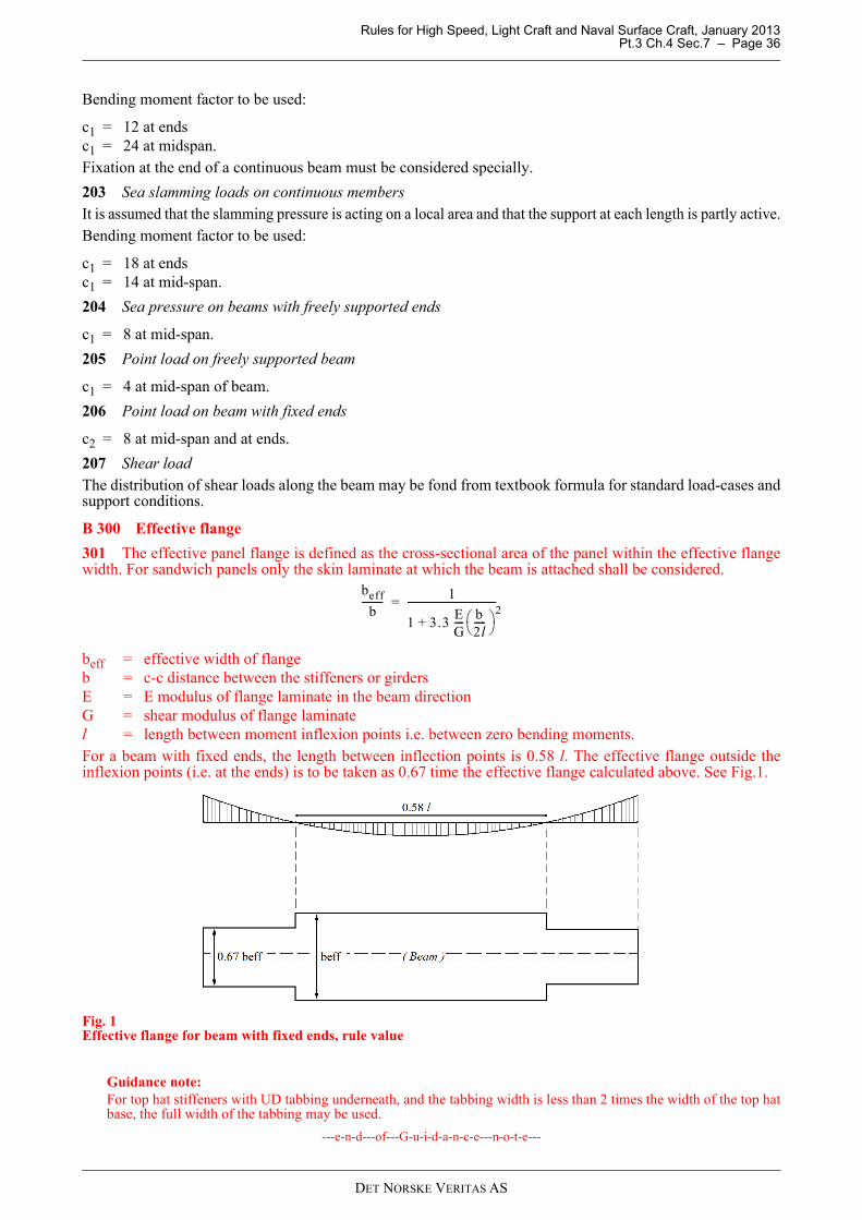
Rules for High Speed, Light Craft and Naval Surface Craft, January 2013 Pt.3 Ch.4 Sec.7 – Page 36
Bending moment factor to be used:
c1 = 12 at endsc1 = 24 at midspan.Fixation at the end of a continuous beam must be considered specially.
203 Sea slamming loads on continuous membersIt is assumed that the slamming pressure is acting on a local area and that the support at each length is partly active.Bending moment factor to be used:
c1 = 18 at endsc1 = 14 at mid-span.
204 Sea pressure on beams with freely supported ends
c1 = 8 at mid-span.
205 Point load on freely supported beam
c1 = 4 at mid-span of beam.
206 Point load on beam with fixed ends
c2 = 8 at mid-span and at ends.
207 Shear loadThe distribution of shear loads along the beam may be fond from textbook formula for standard load-cases andsupport conditions.
B 300 Effective flange
301 The effective panel flange is defined as the cross-sectional area of the panel within the effective flangewidth. For sandwich panels only the skin laminate at which the beam is attached shall be considered.
beff = effective width of flangeb = c-c distance between the stiffeners or girdersE = E modulus of flange laminate in the beam directionG = shear modulus of flange laminatel = length between moment inflexion points i.e. between zero bending moments.For a beam with fixed ends, the length between inflection points is 0.58 l. The effective flange outside theinflexion points (i.e. at the ends) is to be taken as 0.67 time the effective flange calculated above. See Fig.1.
Fig. 1Effective flange for beam with fixed ends, rule value
Guidance note:For top hat stiffeners with UD tabbing underneath, and the tabbing width is less than 2 times the width of the top hatbase, the full width of the tabbing may be used.
---e-n-d---of---G-u-i-d-a-n-c-e---n-o-t-e---
beff
b--------- 1
1 3.3EG---- b
2l----- 2
+
-------------------------------------=
DET NORSKE VERITAS AS
Rules for High Speed, Light Craft and Naval Surface Craft, January 2013 Pt.3 Ch.4 Sec.7 – Page 37
B 400 Effective web
401 Holes in girders will generally be accepted provided the shear stress level is acceptable and the bucklingstrength is sufficient. Holes are to be kept well clear of end of brackets and locations where shear stresses arehigh.
402 For ordinary girder cross-sections the effective web area is to be taken as:AW = 0.01 hn tw (cm2)
hn = net girder height in mm after deduction of cutouts in the cross-section considered.
If an opening is located at a distance less than h/3 from the cross-section considered, hn is to be taken as thesmaller of the net height and the net distance through the opening. See Fig.3.
403 Where the girder flange is not perpendicular to the considered cross section in the girder, the effectiveweb area is to be taken as:
hn = as given in 402AFL = flange area in cm2
Θ = angle of slope of continuous flange.
See also Fig.4.
B 500 Effective bond area
501 For girders attached to other structural members at their supports by secondary bonding the effectivebond area is determined by the following formula:
AB = B H – b hSee Fig.5.
B 600 Strength requirements
601 Bending strength of beams of uniform cross section Beams of uniform cross section are defined as having the same material properties for the web, flange and theoverlay material. The laminate used in simple beams must be able to carry both tension loads in the flange andshear loads in the web.
Guidance note:A laminate with [0, 90°] or [± 45°] is not suitable for both tension and shear loading found in a beam. A choppedstrand mat or a multi-axial laminate would be suitable.
---e-n-d---of---G-u-i-d-a-n-c-e---n-o-t-e---
The section modulus of beams with uniform material properties in the cross section subjected to lateral pressureis not to be less than:
M = bending moment at the cross sectionσ d= design stress (see Table C1)
602 Built-up beamsBeams with different lay-up in web and flange is considered to be built-up beams. Typical example is a beamwith unidirectional capping on top.Variation in the modulus of elasticity is to be taken into account when calculating cross section properties ofthe beam.Bending stress is to be checked both at the mid-span and at the ends. For beams with mechanical propertiesvarying along the beam, the weakest sections must be checked.The stress level in each laminate shall not exceed the design stress values given in Table C1.
Guidance note:The acceptance requirement may also be expressed in traditional terms:The effective section modulus is not to be less than:
Aw 0.01 hn tw 1.3 AFL 2 Θ Θ cm2( )sinsin+=
ZMσd------=
DET NORSKE VERITAS AS
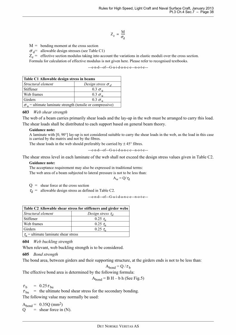
Rules for High Speed, Light Craft and Naval Surface Craft, January 2013 Pt.3 Ch.4 Sec.7 – Page 38
M = bending moment at the cross sectionσ d= allowable design stresses (see Table C1)Ze = effective section modulus taking into account the variations in elastic moduli over the cross section.Formula for calculation of effective modulus is not given here. Please refer to recognised textbooks.
---e-n-d---of---G-u-i-d-a-n-c-e---n-o-t-e---
603 Web shear strengthThe web of a beam carries primarily shear loads and the lay-up in the web must be arranged to carry this load.The shear loads shall be distributed to each support based on general beam theory.
Guidance note:A laminate with [0, 90°] lay-up is not considered suitable to carry the shear loads in the web, as the load in this caseis carried by the matrix and not by the fibres. The shear loads in the web should preferably be carried by ± 45° fibres.
---e-n-d---of---G-u-i-d-a-n-c-e---n-o-t-e---
The shear stress level in each laminate of the web shall not exceed the design stress values given in Table C2.Guidance note:The acceptance requirement may also be expressed in traditional terms:The web area of a beam subjected to lateral pressure is not to be less than:
Aw = Q/τd
Q = shear force at the cross sectionτd = allowable design stress as defined in Table C2.
---e-n-d---of---G-u-i-d-a-n-c-e---n-o-t-e---
604 Web buckling strengthWhen relevant, web buckling strength is to be considered.
605 Bond strengthThe bond area, between girders and their supporting structure, at the girders ends is not to be less than:
Abond = Q /τ bThe effective bond area is determined by the following formula:
Abond = B H – b h (See Fig.5)
τ b = 0.25τ buτ bu = the ultimate bond shear stress for the secondary bonding.The following value may normally be used:
Abond = 0.35Q (mm2)Q = shear force in (N).
Table C1 Allowable design stress in beamsStructural element Design stress σ dStiffener 0.3 σ uWeb frames 0.3 σ uGirders 0.3 σ uσ u = ultimate laminate strength (tensile or compressive)
Table C2 Allowable shear stress for stiffeners and girder websStructural element Design stress τdStiffener 0.25 τuWeb frames 0.25 τuGirders 0.25 τuτu = ultimate laminate shear stress
ZeMσd------=
DET NORSKE VERITAS AS
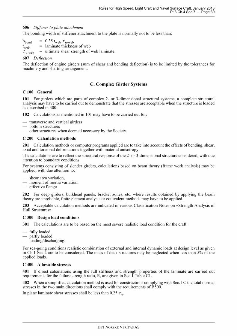
Rules for High Speed, Light Craft and Naval Surface Craft, January 2013 Pt.3 Ch.4 Sec.7 – Page 39
606 Stiffener to plate attachmentThe bonding width of stiffener attachment to the plate is normally not to be less than:
bbond = 0.35 tweb τ u-webtweb = laminate thickness of webτ u-web = ultimate shear strength of web laminate.
607 DeflectionThe deflection of engine girders (sum of shear and bending deflection) is to be limited by the tolerances formachinery and shafting arrangement.
C. Complex Girder Systems
C 100 General
101 For girders which are parts of complex 2- or 3-dimensional structural systems, a complete structuralanalysis may have to be carried out to demonstrate that the stresses are acceptable when the structure is loadedas described in 300.
102 Calculations as mentioned in 101 may have to be carried out for:
— transverse and vertical girders— bottom structures— other structures when deemed necessary by the Society.
C 200 Calculation methods
201 Calculation methods or computer programs applied are to take into account the effects of bending, shear,axial and torsional deformations together with material anisotropy.The calculations are to reflect the structural response of the 2- or 3-dimensional structure considered, with dueattention to boundary conditions.For systems consisting of slender girders, calculations based on beam theory (frame work analysis) may beapplied, with due attention to:
— shear area variation,— moment of inertia variation,— effective flange.
202 For deep girders, bulkhead panels, bracket zones, etc. where results obtained by applying the beamtheory are unreliable, finite element analysis or equivalent methods may have to be applied.
203 Acceptable calculation methods are indicated in various Classification Notes on «Strength Analysis ofHull Structures».
C 300 Design load conditions
301 The calculations are to be based on the most severe realistic load condition for the craft:
— fully loaded— partly loaded— loading/discharging.
For sea-going conditions realistic combination of external and internal dynamic loads at design level as givenin Ch.1 Sec.2 are to be considered. The mass of deck structures may be neglected when less than 5% of theapplied loads.
C 400 Allowable stresses
401 If direct calculations using the full stiffness and strength properties of the laminate are carried outrequirements for the failure strength ratio, R, are given in Sec.1 Table C1.
402 When a simplified calculation method is used for constructions complying with Sec.1 C the total normalstresses in the two main directions shall comply with the requirements of B500.In plane laminate shear stresses shall be less than 0.25 τ u.
DET NORSKE VERITAS AS
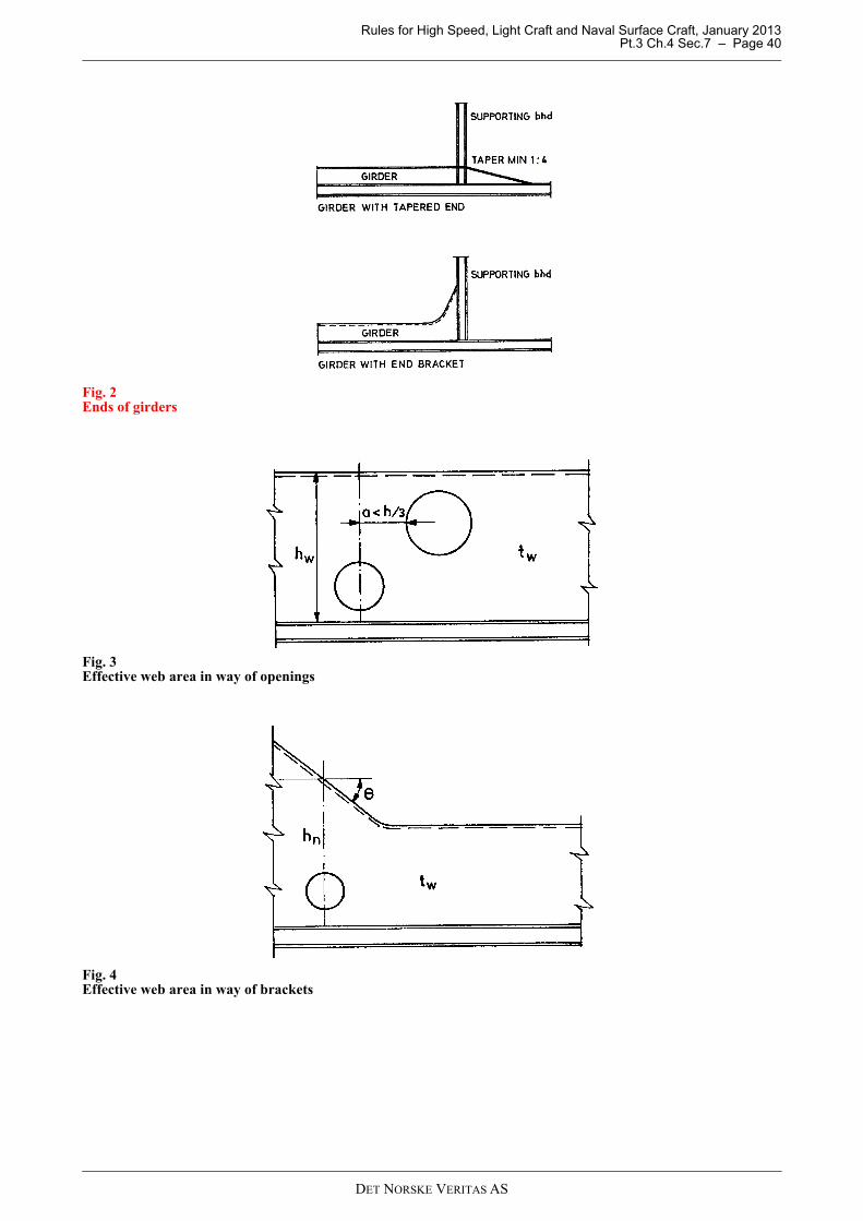
Rules for High Speed, Light Craft and Naval Surface Craft, January 2013 Pt.3 Ch.4 Sec.7 – Page 40
Fig. 2Ends of girders
Fig. 3Effective web area in way of openings
Fig. 4Effective web area in way of brackets
DET NORSKE VERITAS AS
Rules for High Speed, Light Craft and Naval Surface Craft, January 2013 Pt.3 Ch.4 Sec.7 – Page 41
Fig. 5Effective bond area
DET NORSKE VERITAS AS

Rules for High Speed, Light Craft and Naval Surface Craft, January 2013 Pt.3 Ch.4 Sec.8 – Page 42
SECTION 8 BONDED JOINTS
A. General
A 100 Application
101 This Section applies to a bonded joint defined as follows: a joint where adherents are bonded either byplacing a layer of adhesive or resin material between the adherents or by producing a bond between oneadherent and the second adherent as an integral part of the manufacturing of the joint or the structure, e.g. byapplying laminates or laminating directly onto a metal surface, or any combination of the above. Secondarybonds in FRP constructions are not covered by this section.
102 The use of bonded joints is subject to the approval of the Society. Bonded joints are not accepted fortransfer of the global loads on the hull or on joints the failure of which would compromise the watertightintegrity of the vessel.
103 Adhesives used for bonded joints shall be type approved by DNV.
B. Design
B 100 Design of bonded joints
101 The function(s) of the joint shall be clearly specified.
102 The nominal shear stress over the bond surface shall not by itself be used as a characteristic of the loadlevel in the joint. The design shall be based on line load, global load or an analysis of the shear stress takingdue account of the stress concentrations in the joint.
103 The physical environment of the joint shall be specified and considered in the design. As a minimum thefollowing factors shall be considered:
— humidity— UV-light— temperature— chemicals (e.g. fuel etc.)— welding— fire.
Welding on adjacent structures and fire may increase the temperature at the bond. This effect shall beconsidered when specifying short and long term service temperature for the joint.
104 The design of bonded joints shall be based on qualification tests carried out on realistic samples, seeC100. The properties obtained in a yard may differ significantly from the properties measured on specimenstested under laboratory conditions. Causes for such differences may be different working environment, scalingeffects etc. This difference shall be reflected in the design strength of the joint: the strength of the joint cannotbe assumed to be as high as determined in the qualification tests.
105 The load on the joint shall not exceed the characteristic strength determined in the qualification testsdivided by a factor of 5.0.
106 The adherents, surface preparation and fabrication procedures shall be identical to the joint as for thesamples on which the qualification tests have been carried out.
107 The joint cross section and the direction of the load transfer shall for all parameters influencing thestrength and durability of the joint be identical to the joint geometry tested in the qualification tests.Alternatively, a change in any of these parameters may be accepted if they do not lead to a reduction of thestrength or durability of the joint. Special attention shall be given to the length of the overlap, the stiffness of the adherents and the out-of planeforces in the joint. The length of the overlap shall not be smaller than on the tested joint. The thickness of theadherents shall not be smaller than used in the qualification tests.
DET NORSKE VERITAS AS

Rules for High Speed, Light Craft and Naval Surface Craft, January 2013 Pt.3 Ch.4 Sec.8 – Page 43
C. Qualification
C 100 Qualification tests
101 Qualification tests shall be carried out on samples representing the actual adherents, surface preparation,joint geometry and fabrication conditions in a realistic manner. Great care shall be taken to represent out-of-plane forces in the joint, also in a joint designed to transfer in-plane loads only. Adhesive properties shall not be determined as bulk properties of the adhesive itself, but always including theeffect of joint configuration, adherents etc.
102 Both initial properties and time dependent properties of materials shall be determined or tested asrelevant. The environmental conditions specified for the design of the joint shall be considered, B103.
103 The samples shall be tested after realistic ageing considering the factors above. Alternatively, the ageingeffect on the actual combination of adhesive and substrate determined in previous tests may be used to quantifythe degradation over time of the bond strength.
104 For each test condition, five parallel tests shall be carried out. The characteristic strength shall bedetermined as the second lowest value obtained. The lowest value shall not be lower than 80% of the secondlowest. It shall be recorded for each specimen whether the failure is cohesive or adhesive.
DET NORSKE VERITAS AS
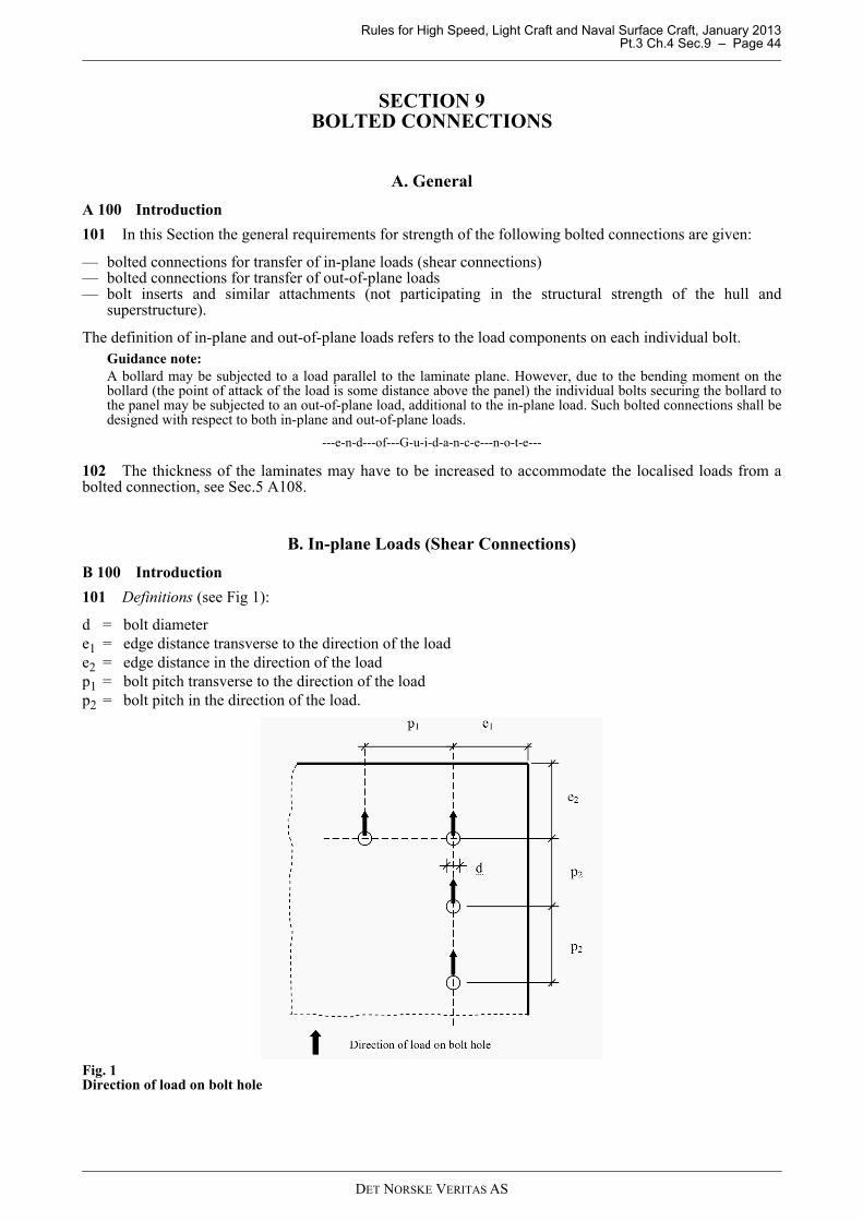
Rules for High Speed, Light Craft and Naval Surface Craft, January 2013 Pt.3 Ch.4 Sec.9 – Page 44
SECTION 9 BOLTED CONNECTIONS
A. General
A 100 Introduction
101 In this Section the general requirements for strength of the following bolted connections are given:
— bolted connections for transfer of in-plane loads (shear connections)— bolted connections for transfer of out-of-plane loads— bolt inserts and similar attachments (not participating in the structural strength of the hull and
superstructure).
The definition of in-plane and out-of-plane loads refers to the load components on each individual bolt. Guidance note:A bollard may be subjected to a load parallel to the laminate plane. However, due to the bending moment on thebollard (the point of attack of the load is some distance above the panel) the individual bolts securing the bollard tothe panel may be subjected to an out-of-plane load, additional to the in-plane load. Such bolted connections shall bedesigned with respect to both in-plane and out-of-plane loads.
---e-n-d---of---G-u-i-d-a-n-c-e---n-o-t-e---
102 The thickness of the laminates may have to be increased to accommodate the localised loads from abolted connection, see Sec.5 A108.
B. In-plane Loads (Shear Connections)
B 100 Introduction
101 Definitions (see Fig 1):
d = bolt diametere1 = edge distance transverse to the direction of the loade2 = edge distance in the direction of the load p1 = bolt pitch transverse to the direction of the loadp2 = bolt pitch in the direction of the load.
Fig. 1Direction of load on bolt hole
DET NORSKE VERITAS AS
Rules for High Speed, Light Craft and Naval Surface Craft, January 2013 Pt.3 Ch.4 Sec.9 – Page 45
B 200 Minimum requirements
201 Bolted shear connections are only accepted in laminates with reinforcement placed in at least twodirections. The smallest angle between at least two reinforcement directions shall not be smaller than 75° (doesnot apply to pure CSM laminates). CSM plies in a combined laminate shall not be included in the calculationof the capacity of the connection.
202 The surface of the part of the bolt inside the laminate shall be smooth. No threads are allowed in this area.
203 A washer with an outer diameter not smaller than 3 d shall be used under the bolt head and the nut. Thewasher shall have adequate stiffness such that the bolt pretension is distribute under the area of the washer.Only flat-face bolts shall be used. Countersunk/tapered bolt heads are not accepted due to the risk for splittingthe laminate by the wedge effect of the bolt head.
204 The bolt shall be tightened with such a force that the laminate is subjected to a nominal compressivestress under the washers, exceeding 15 MPa but not exceeding 30 MPa. The nominal stress is calculated ascompressive load in the bolt divided by the surface area of the washer. Due to the creep (and thus stressrelaxation) that can be expected in the laminate, bolts should be re-torqued after a period of time not shorterthan 2 weeks.
205 The pitch transverse to the direction of the load shall satisfy p1 ≥ 5 d. The pitch in the direction of the load shall satisfy p2 ≥ 4 d. The edge distance transverse to the direction of the load shall satisfy e1 ≥ 3 d.The edge distance in the direction of the load shall satisfy the following requirement:e2 ≥ 4 d.
206 The nominal bearing stress shall satisfy the following requirement:
σ bear = shear load divided by d · tt = thickness of structural laminateγ = 1.0 for holes with a difference between bolt and hole diameter less than 0.1 mmγ = 1.6 for holes with a difference between bolt and hole diameter of less than 1.0 mmThe default values of the bearing stress capacity given in Table B1 can be used.
Higher bearing stress capacity can be used based on representative test results.For hybrid laminates Rbear can be found by liner interpolation based on the volume fraction of the respectivetypes of fibre.
Guidance note:The requirements are such that it is highly probable that the failure mode will be that the bearing stress will exceedthe capacity around the edge of the hole.
---e-n-d---of---G-u-i-d-a-n-c-e---n-o-t-e---
Table B1 Default values of the bearing stress capacityType of reinforcement Nominal bearing stress strength,
Rbear (MPa)Glass, woven rowing 200 (Vf/0.33)Glass, multiaxial laminates 250 (Vf/0.33)Glass, CSM 75 (Vf/0.33)Carbon, woven rowing 275 (Vf/0.50)Carbon, multiaxial laminates 325 (Vf/0.50)Aramid, woven rowing Considered speciallyAramid, multiaxial laminates Considered speciallyVf = volume fraction of reinforcement in laminates excluding CSM
σbear
Rbear
3 γ-------------=
DET NORSKE VERITAS AS
Rules for High Speed, Light Craft and Naval Surface Craft, January 2013 Pt.3 Ch.4 Sec.9 – Page 46
C. Out-of-plane Loads
C 100 General
101 A connection for out-of–plane loads shall be bolted through the panel, in sandwich panels through bothskins. For attachments not participating in the structural strength of the hull and superstructure otherarrangements may be accepted by the Society.
102 Washers or plates shall be provided on both sides of the panel to distribute the load from bolt heads andnuts. These washers or plates may be fabricated from metallic materials or from fibre reinforced thermosets.Their bending stiffness shall be large enough to ensure a distribution of the load from each bolt over asufficiently large area to prevent compressive overloading of the panel in-between the washers or plates. Thecompressive stress under the washer or plates shall not anywhere exceed 30% of the compressive strength ofthe skin and core, respectively.
103 The global effect of the out-of-plane load on the panel (in-plane bending moments and through thicknessshear) shall be calculated according to recognised methods for the calculation of load effects in panelssubjected to concentrated loads. The stress levels in laminates, skins and core shall not exceed the stress levelaccepted for hull panels in bottom exposed to slamming.
104 Other arrangements may be accepted based on test results. Such testing shall be carried out onconnections with representative design on representative panels subjected to representative loads including allin-plane and out-of-plane components. The allowable loads on the connection shall not exceed the loweststrength recorded from at least three such test divided by the factor of 3.
D. Inserts and Attachments
D 100 General
101 Inserts and attachments may be used for transferring in-plane and out-of-plane loads for connections notparticipating in the structural strength of the hull and superstructure.
102 Where adequate, the methods for design described above may be used. Where these methods are notadequate the allowable load shall be determined by testing. Such testing shall be carried out on inserts orattachments with representative design on representative panels subjected to representative loads including allin-plane and out-of-plane components. The allowable loads on the insert/attachment shall not exceed the loweststrength recorded from at least three such test divided by the factor of 3.
DET NORSKE VERITAS AS

Rules for High Speed, Light Craft and Naval Surface Craft, January 2013 Pt.3 Ch.4 Sec.10 – Page 47
SECTION 10 BUCKLING
A. General
A 100 General
101 For panels, beams and columns with stress levels not exceeding the allowable stress levels given in theseRules, global buckling may be assumed to be linear, i.e. a linear analysis may be used when calculating thecritical buckling load or stress.
102 Standard textbook formulas using a conservative estimate of in-plane and bending moduli of the laminatemay be used considering the requirements given in this Section. More rigorous formulas based on the completestiffness matrix of the laminate may also be used.
103 The effect of imperfections, i.e. deviations from the idealised geometry shall be considered in theanalysis.
104 It is assumed that the laminates in the components are orthotropic. For other types of laminates a morerigorous analysis is necessary.
105 The edge or end constraints of the component (e.g. constraints against out-of-plane rotation at the edgesof a panel) shall be reflected in the analysis in a manner that is as realistic as practical. In a carefully modelledand executed FEM-analyses it may be assumed that edge or end constraints are realistic. When using standard textbook formulas, solutions for correct edge constraints are seldom available (e.g. thepartial constraint against out-of-plane rotation at the edges of a panel in a continuous plate field). Forcomponents with significant but partial edge or end restraint the critical buckling load can be calculated as 1.8times the critical load for the cases of no restraint against rotation, except as specified by other requirements inthis Section.
106 The allowable load or stress level with respect to buckling shall be equal to the critical load or stress,based on a conservative analysis, reduced by the safety factor given in Table A1. For analysis where the effectof geometrical imperfections has been included in a realistic manner the factor may be increased, subject to theapproval by the Society.
B. Single Skin Panels
B 100 Single skin panels
101 The global buckling resistance of single skin panels may be analysed applying recognised textbookbuckling formulations available for isotropic materials. The lowest modulus of the laminate in its two principaldirections shall be chosen as representative of the laminate. Due regard shall be given to the possible differenceof the bending modulus to the in-plane modulus of the panel.
102 In lieu of a more rigorous analysis the critical buckling stress for a rectangular orthotropic plane panel ina larger plate field, loaded parallel to it’s longest edge, can be calculated according to the following equation:
b = length of shortest edge of the panel (mm)t = plate thickness (mm)σ cr = critical buckling stress (MPa)
Table A1 Safety factorsBuckling mode Safety factorGlobal buckling of sandwich and single skin panels 0.40Shear buckling of sandwich panels 0.40Global buckling of girders, frames, stiffeners 0.33Local buckling of top flanges of girders, frames, stiffeners 0.40Local shear buckling of webs girders, frames, stiffeners 0.40Global buckling of columns 0.40
σcr KE
1 ν2–
-------------- tb--- 2
=
DET NORSKE VERITAS AS
Rules for High Speed, Light Craft and Naval Surface Craft, January 2013 Pt.3 Ch.4 Sec.10 – Page 48
E = smallest flexural modulus of the two principal directions of the panel (MPa)= largest Poisson ratio
K = 3.3 when all edges simply supportedK = 6.0 when all edges clampedK = 4.4 when all edges partially fixed 1)
1) Panel being supported along its four edges and connected to adjacent panels providing a partial rotationalrestraint.
103 For panels where the difference between the modulus in the two principal directions is large a morerigorous analysis may be necessary to determine a more realistic buckling resistance.
C. Sandwich Panels
C 100 Sandwich panels
101 All relevant buckling modes shall be considered: global buckling, shear buckling, face wrinkling andface dimpling.
102 The global buckling resistance of sandwich panels shall be analysed using standard textbook formulasfor buckling of sandwich panels. When relevant, the combined effect of global and shear buckling shall beconsidered.
103 In lieu of a more rigorous treatment the critical buckling stress for a rectangular orthotropic planesandwich panel in a larger plate field, loaded parallel to it’s longest edge, can be calculated according to thefollowing equation:
b = length of shortest edge of the panel (mm)t = thickness of skin laminates (mm)σ cr = critical buckling stress (MPa)
= critical buckling stress with respect to global buckling (MPa)
= critical buckling stress with respect to shear buckling (MPa)D = bending stiffness per unit of length, E I (Nmm)I = moment of inertia pr unit of length (mm4/mm)E = modulus in the loaded direction of the skin laminates (MPa)S = Gc d2/tc (N/mm)Gc = core shear modulus (MPa)tc = core thickness (mm)d = distance between centre of skin laminates (mm)K = 40The equation is based on the panel being supported along its four edges and that it is connected to adjacentpanels providing partial rotational restraint.
104 For panels where the difference between the modulus in the two principal directions is very large a morerigorous analysis may be necessary to determine a more realistic buckling resistance.
1σcr------- 1
σcrb
---------- 1
σcrS
----------+=
σcrb
KD
2t b2
-----------=
σcrS S
2 t-----=
σ crb
σ crS
DET NORSKE VERITAS AS

Rules for High Speed, Light Craft and Naval Surface Craft, January 2013 Pt.3 Ch.4 Sec.10 – Page 49
D. Beams, Girders and Stringers
D 100 Beams, girders and stringers
101 Beams, girders, stringers etc. shall be analysed with respect to global buckling due to axial compression. Theflanges and webs shall be analysed with respect to local buckling due to axial load, bending moment and shear load.
102 For closed section beams with adequate stiffness or support with respect to tripping, the critical axialglobal buckling load is given by:
D = bending stiffness of the beam with associated plating, EI (Nmm2)l = the free span of the beam (mm)DQ = tw hw Gw (Nmm2)tw = combined thickness of stiffener web(s) (sum of all web thicknesses) (mm)hw = height of the beam web (mm)Gw = shear modulus of the beam web (MPa)
103 The critical axial stress in the top flange of top-hat cross sections not supported by a structural core canbe calculated as for single skin panels.
104 The critical shear stress with respect to shear buckling in the webs of stiffeners not supported bystructural core material may be calculated according to the following equation for ±45º lay-ups:
τcr = 90 · D11/(hw2 · tw) (N/mm2) carbon fibre
τcr = 80 · D11/(hw2 · tw) (N/mm2) glass fibre
hw = height of web (mm)tw = thickness of web laminate (mm)D11 = flexural stiffness of the web laminate in the longitudinal direction of the web/stiffener = (Nmm)
(For ±45º lay-ups D11 = D22)
For other laminate lay-ups the critical shear stress, τcr, may be calculated according to the following equation:
τcr = K · (D11· D223)1/4/(hw
2 · tw) (N/mm2) K = 44.0 + 25.8·α – 2.95·α2 + 0.25·α3
valid for a < 5α = (D12 + 2 · D66)/(D11·D22)1/2
D22 = flexural stiffness of the web laminate perpendicular to the longitudinal direction of the web/stiffener (Nmm)
D12 = υ12 · D22 = υ21 · D11 (Nmm)D66 = twisting stiffness of the laminate (Nmm)υ12, υ21 = Poisson’s ratios for the web laminateThe shear stress shall not exceed τcr.Alternative more rigorous methods for calculating the buckling capacity of webs may be accepted.
E. Stiffened Plate Field
E 100 Stiffened plate field
101 Stiffened plate fields can be analysed using formulas developed for such structures fabricated from steelprovided conservative assumptions are made regarding the stiffness of cross sections of stiffeners and platingare made.
F. Columns
F 100 Columns
101 The critical load of columns can be calculated according the standard Euler formulas for global bucklingof columns.
Paπ 2
l2
----- D
1π 2
D
l2DQ
------------+ ---------------------------=
DET NORSKE VERITAS AS