Embed Size (px)
Citation preview

Running start Absolute Beginners
– with video tutorial
Firstly WATCH THE VIDEOS.
Then READ EVERYTHING. It is there to help not be ignored. This Tutorial covers all the problems a first-time user may suffer from, and how to correct them yourself. You will need your logbook to make notes, get it out of your bag now. If you find yourself going wrong, go back and repeat a step. Use this document as a term of reference in future it will always be available. Many final year students still make mistakes they could avoid if they only read this document more thoroughly. Answer all questions in your logbook.
Instructions – Start Here
- Follow every step in order, ie 1, 2, 3…etc (surprisingly, many struggle with this). - Do not skip steps, as this will only confuse you later. - Read everything. - If you make a mistake, go back and read through the step again. - I repeat. If you make a mistake, go back and read through the step again. - Very Important details will be highlighted in yellow, like this box. Pay extra attention to them. These are the
things you need to remember. Read them. Re-read them. Read them one last time, then, move on.
- Have your Logbook out to make notes. Do it now!! This is the item you will construct. It’s nothing exciting but then neither are door handles and somebody has to design those too.

1Click ‘Maximise’ to make the window full screen. Big monitor, make things easier for yourself.
2Hold ‘Alt’ on the keyboard and click ‘Tab’ to cycle through open windows.
> This will help you swap between this tutorial and CATIA and any other windows you have open. Learn to use this now, and these tutorials will be much easier. Your screen might look different from this or the video, but it does the same function.
3 When CATIA opens you will see a screen like this.
You’ll be left with this. Now we’re ready to start. Remember, do not move on until you have completed this. If you don’t see this, go back and re-read steps 1-3.
Press Close Here
Then close the inner window.

4 CATIA works with a series of workbenches or ‘Modules’. Each contains a different set of tools for doing
different things. This tutorial will make a single component or a ‘Part’, so we need to open the Part Design module.
Start > Mechanical Design > Part Design
5 CATIA works like this.
Every feature generally has a sketch driving it. Sketches work off ‘Planes’, which ‘supports’ the ‘profile’. A plane is simply a flat surface that is sketched on. Think of it like a table, you’d lean on a table to sketch on a piece of paper wouldn’t you? A plane is just like that.
Click OK on New Part

6 Click > then click (YZ Plane) in the middle of the screen.
Use Left Mouse Button (LMB) unless otherwise instructed to.
Your screen should look a bit like this.
Notice all the tools down the right hand side have changed. Also notice that we have swapped into another module, the ‘Sketcher’ module. This is signified by the symbol in the top right of the screen.
We were in Part Design ,
we’re now in Sketcher. Pay Attention to this.
7In CATIA, many tools are ‘stacked’ under others, you can open this stack by pressing the little arrow underneath
a button. Underneath this rectangtle is this toolbar. Click ‘Centred Rectangle’.

8 When sketching CATIA, all sketches must be constrained. The one thing you can see on the screen that you
can constrain to is the ‘Origin’ represented by this symbol. V means vertical, H means horizontal. Don’t laugh, I’ve had to explain this many times.
As you can see it’s centre is 0,0 (think vector mechanics). This will not move, so everything must be constrained to this. There’s no clicking and dragging in Sketcher. Single click. Let go of the mouse button and move it to where you want the profile line to go, then click again to commit the command. Remember, single click. Click on the 0,0 ensuring you see this symbol. This is very important. Do not click and drag. You’ll see as you move the cursor up and to the right co-ordinates appear next to it. This is effectively 50 mm wide by 50 mm tall.
Click the LMB again. Giving this.
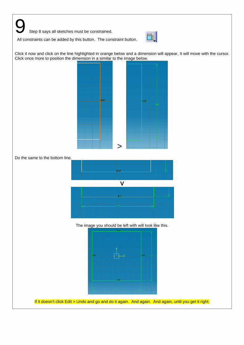
9 Step 8 says all sketches must be constrained.
All constraints can be added by this button. The constraint button. Click it now and click on the line highlighted in orange below and a dimension will appear, It will move with the cursor. Click once more to position the dimension in a similar to the image below.
> Do the same to the bottom line.
V
The image you should be left with will look like this.
If it doesn’t click Edit > Undo and go and do it again. And again. And again, until you get it right.

Understanding Checkpoint. If you can’t answer these questions. You must not move on. It’s vital that you know these points as they’re the absolute basics. If you can’t answer them, go back and read steps 1-9 again. Twice if necessary.
- To draw a sketch you need a____?
- What were the two letters used to describe the support for the first sketch?
- All features in a CATIA need a _____ first?
- In a sketch, what doesn’t move?
- So how do you prevent profiles moving about?
- What are the co-ordinates at the centre of a sketch?
- What does the term stacked mean?
- How do you access stacked buttons?
- What does LMB stand for?
- Therefore, what might MMB and RMB stand for?
Write these questions and answers in your logbook so you do not forget them.
When you’ve answered these questions, you may move on.

10 Click to exit Sketcher module.
You’ll change from Sketcher to Part Design. . So pay attention to this symbol.
Your screen should look like this.
11With the profile highlighted, click Pad . If it isn’t highlighted orange, LMB click it once. Not twice.
Enter 40mm in the highlighted ‘Length’ field, then press preview.
When you’re comfortable with the result Click OK.

12 How to manipulate the model using the mouse.
Write this in your Logbook now.
All of these commands are completed with the MMB clicked the entire time. Keep it clicked. Do not scroll. Pan = MMB Rotate = MMB + RMB Zoom = MMB +click RMB then release, keep MMB held Pan = Translates model up, down, left and right. Rotate = Rotates model through 360 Zoom = Magnifies and reduces model. Try it now. Try it again. Try it again. To return to Home View (Isometric) click these buttons in the correct order.
then They’re located on the bottom toolbar. It’s very important you learn how to control the model using the mouse. It will make using CATIA a lot easier and smoother. Practice it again now and use the ‘isometric’ button and ‘fit all in’ button above to return to home.
LMB Left Mouse Button
MMB Middle
RMB Right Mouse Button
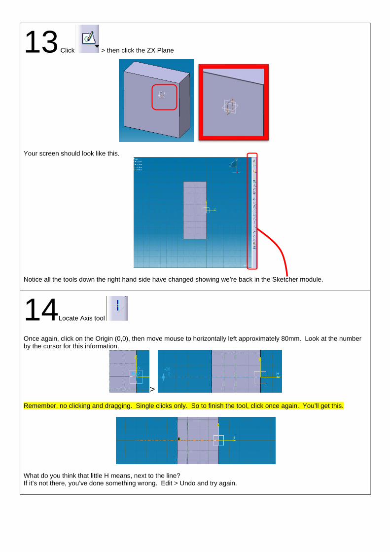
13 Click > then click the ZX Plane
Your screen should look like this.
Notice all the tools down the right hand side have changed showing we’re back in the Sketcher module.
14Locate Axis tool
Once again, click on the Origin (0,0), then move mouse to horizontally left approximately 80mm. Look at the number by the cursor for this information.
> Remember, no clicking and dragging. Single clicks only. So to finish the tool, click once again. You’ll get this.
What do you think that little H means, next to the line? If it’s not there, you’ve done something wrong. Edit > Undo and try again.

15 Locate the Rectangle Tool, which is now ‘stacked’ underneath the Centred Rectangle. If you
don’t know what stacked means, you’ve not answered the questions above. Go back and read them again. Starting from the top left, draw a rectangle like this. Remember rules about clicking and dragging. Make the rectangle about the same size as the image, you don’t need exact sizes yet.
Use the Constraint tool to add the dimensions in the image below. Don’t forget to add the dimension to constrain the box to the axis line.
Use the constraint tool again to add the dimension below. See that two lines are highlight red in the image, select them in the order as numbered
Select first Select second

16 After you’ve positioned the last dimension, double-click it and type 0mm.
You should have this. Notice the profile you’ve just drawn is stuck to the Pad you made previously. Does this mean
that you can draw profiles then use the Constraint tool to resize them and move them into place? I think it does. Write that in your Logbook.
If you haven’t you’ve done something wrong. Edit > Undo and try it again.
Click to exit Sketcher module.
Understanding Checkpoint
In Sketcher, the colour of the line is very significant. Right the points below into your Logbook. They’re very important.
- A white line means a profile is not fully constrained. You must add dimensions to it to ensure it is. - A green line means a profile is fully constrained. An item must be fully constrained before you exit Sketcher. - A purple line means a profile is over constrained. This means there are more dimensions than necessary and
some must be removed for the profile to work. Return to Home View (Isometric) click these buttons in the correct order.
then

17 Click the Shaft button.
Leave the details as they are, but click the Preview button to give the image above. When you’re happy with it, click OK.
18 Click the white line on the Part Tree
You should see the part turn from a vivid grey to a dim colour. Press again and it will turn back. Pay attention to this as you attempt the next step. Ensure the Part is always a vivid grey.
>
19 Click the ‘Plus’ symbol on the Part Tree. If you click the white line accidentally, you know what to do.
>

20 Double Click Sketch.2 , in the Part Tree. It will open up the Sketcher module. Change the highlighted dimension to 40mm.
Click to exit Sketcher module. Then and .
21 Deselect everything on screen. (LMB click once somewhere on the screen in the model space, ensuring nothing is selected.) Then click Hole and Click on the front face.
The Hole definition window will open. Then click Sketch.

22The star/asterisk represents the hole centre. Add the following dimensions so that it turns green.
Remember what green means?
Click to exit Sketcher module. Ensure your values are the same as the image below and click OK.
You should have this.

23Deselect everything again. To use this next tool you need to ‘pre-select’ items in the Part Tree.
You’ll also have to find the toolbar which maybe hidden. In the zoomed image below you can see a small grey line that is highlighted. This means there are more toolbars hidden off-screen. This is the one occasion you may click and drag.
Click the little grey line and pull out enough toolbars to find this one. Deselect everything again. Perform the next few steps in precisely the correct order. Single LMB ‘Hole.1’ in the Part Tree Then click Rectangular Pattern. You should see the following dialogue box.
Click ‘Reference Element’ so it’s highlighted blue, then click this front face.

24
Change the values in the ‘First Direction’ and ‘Second Direction’ Tab to the following.
Click Preview You may need to click ‘Reverse’ so that you get the following image.
When you have the correct image click OK to continue. If you haven’t click cancel, Edit > Undo if necessary, and try it again.
25 Double Click Hole.1 in the Part Tree. Under the ‘Type’ tab, change the drop down menu to ‘Counterbored’.
Leave the values as they are, Click OK and see what happens to the model. Magic!

26
If like most first time CATIA users you closed this box without thinking you might need it later, this is how you get it back. And any others you may have lost. Click Tools > Customize > Toolbars > Restore Position. Write this in your Logbook now.
27 One last thing. First time users have a habit of clicking this ‘Fly Mode’
by accident. Giving a perspective view, like this below.
To return to Parallel view. View > Render Style > Parallel. Will return to this.
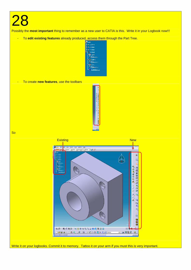
28 Possibly the most important thing to remember as a new user to CATIA is this. Write it in your Logbook now!!!
- To edit existing features already produced, access them through the Part Tree.
- To create new features, use the toolbars
So Existing New
Write it on your logbooks. Commit it to memory. Tattoo it on your arm if you must this is very important.

Understanding Checkpoint. If you can’t answer these questions. You have not finished and should go back and do this again. It’s vital that you know these points as they’re the main things that can go wrong and generally do. If you can’t answer them, go back and do the tutorial again. Twice if necessary.
- The symbol in the top-right corner define what ______ I’m currently using.
- A stacked tool is…?
- Can you click and drag in Sketcher?
- A white line means?
- A green line means?
- A purple line means?
- I can see the difference between light grey and dark grey and what it means.
>
- How do I reset toolbars if I close or lose them accidentally?
- Therefore, what might MMB and RMB stand for?
- To edit features I’ve produced I double click in the _______?
Write these questions and answers in your logbook so you do not forget them.
When you’ve answered these questions, you may move on, and not before.