Embed Size (px)
Citation preview

Runtime Monitoring based on InterfaceSpecifications
Ivan Kurtev1 Jozef Hooman2,3 Mathijs Schuts4
1 Altran, Eindhoven, The Netherlands2 Embedded Systems Innovation by TNO, Eindhoven, The Netherlands
3 Radboud University, Nijmegen, The Netherlands4 Philips, Best, The Netherlands
Abstract. Unclear descriptions of software interfaces between compo-nents often lead to integration issues during development and mainte-nance. To address this, we have developed a framework named ComMA(Component Modeling and Analysis) that supports model-based engi-neering of components. ComMA is a combination of Domain SpecificLanguages (DSLs) for the specification of interface signatures, state ma-chines to express the allowed interaction behaviour, and constraints ondata and timing. From ComMA models a number of artefacts can begenerated automatically such as proxy code, visualizations, tests, andsimulation models. In this paper, the focus is on the generation of run-time monitors to check interface conformance, including the state ma-chine behaviour and the specified data and time constraints. We reportabout the development of this approach in close collaboration with thedevelopment of medical applications at Philips.
1 Introduction
Precise interface descriptions are crucial in the development of complex systemswith many components, including third-party components. Unclarity about in-terfaces is a frequent source of errors. This does not only concern the signatureof messages exchanged between components, but also the expected order of mes-sages, assumptions on timing behaviour, and constraints on the exchanged datavalues. During system development, proper interface definitions are essential toprevent integration issues. During later phases of the system life cycle, contin-uous monitoring of interfaces is important to prevent system failures due tocomponent changes. For instance, a supplier might deliver an improved versionof a component which, however, has different timing characteristics.
The focus of this paper is on the automatic generation of monitoring supportfrom interface specifications. This is done in the context of the development ofminimally-invasive interventional X-ray systems of Philips. An example of sucha system is depicted in Fig. 1.
In order to support the development and usage of precise interface specifi-cations we proposed a framework named ComMA (Component Modeling andAnalysis). ComMA enables model-based engineering of high-tech systems by

Flat Detector
Control Pedals
Tube
C-arm
UI Control
Fig. 1. Interventional X-ray System
formalizing interface specifications. It provides a family of domain-specific lan-guages (DSLs) that integrates existing techniques from formal behavioural andtime modeling and is easily extensible. The most important analysis tool inComMA allows monitoring and checking of component executions against inter-face specifications. The monitoring can be performed for already existing logswith execution traces or by monitoring executions at runtime.
While developing ComMA and its monitoring capabilities we used the industry-as-laboratory approach [12]. This means that tools and techniques are developedin close interaction (e.g. on a daily basis) with real industrial projects. A sim-ilar approach has been applied in an earlier industry-as-lab project on runtimeawareness [2].
The first version of ComMA was a basic domain-specific language and a fewgenerators for glue code, visualisations and very basic monitoring. This pro-vided immediate benefits for the industrial projects and created interest forfurther applications. It also led to a stream of feature requests which have beenincorporated based on user priorities. For instance, inspired by the usefulnessof monitoring timing constraints, users asked for monitoring of advanced dataconstraints. We also added document generation based on requests of users. Bygradually increasing the number of generators and features, we incrementallyadd more value to the projects using the ComMA framework.
As part of our industry-as-lab approach, we had to refactor ComMA basedon new insights we obtained while executing industrial cases. In addition, werefactored the framework to improve maintainability. The initial monolithic lan-guage has been split into a composition of DSLs for types, expressions, statemachines, etc.

The initial component monitoring supported checking of conformance be-tween interfaces and their implementations and checking timing constraints ex-pressed as rules. The rules give the admissible time intervals between events indifferent contexts. Apart from timing behaviour, users were also interested inmonitoring data values. For example, client requests for a given system modewith certain parameters have to match the parameters communicated later bythe system. We developed a new small DSL for expressing only data constraints.It is known from the literature on runtime verification that time information inthe form of event timestamps can be treated in the same way as the data valuescarried by events; they are just data fields associated to events. This observa-tion motivated the unification of data and timing constraints into an underlyinggeneric language which is used to generate the monitoring infrastructure. Thesechanges in the DSLs infrastructure were executed iteratively and remained in-visible for the users. Users could keep using the basic front-end notations fordata and timing constraints and stayed isolated from the changes in the imple-mentation.
The main contribution of this paper is the description of the syntax andsemantics of the generic constraints language. In addition, we also present howthe two existing languages for time and data constraints relate to the genericlanguage.
This paper is organized as follows. Section 2 gives an overview of the relatedwork. An industrial case that provided a motivation and insights for our work ispresented in Section 3. Examples from the case are used to explain the DSLs inComMA (Section 4), and the support for monitoring time and data constraints(Section 5). Section 6 presents the syntax and semantics of the generic constraintslanguage. Section 7 concludes the paper.
2 Related Work
Runtime verification [7, 9] is a technique for monitoring the behaviour of softwareduring its execution and checking if the behaviour conforms to a specification.The literature contains a large number of methods to annotate programs withspecifications and the use of these annotations for runtime checks. Examples aredesign by contract in Eiffel [10] and the Java Modeling Language (JML)[4]. Asa unifying approach, monitor-oriented programming [6] supports runtime moni-toring by integrating specifications in the program via logical annotations, wherea particular specification formalism can be added as a logic plug-in. Actual mon-itoring code is automatically synthesized from these annotations and integratedat appropriate places in the program, according to user-defined configurationattributes of the monitor.
The approach of ComMA is independent of the hardware or software imple-mentation of a component. In our working context, the implementation of manythird-party components is not directly available. The properties are specifiedover traces of component executions. Traces can be obtained via sniffing thenetwork traffic or from logs (if available).

Properties checked during monitoring can be expressed in various formalisms.Examples are logic formulas, automata, and context free grammars. The con-straint languages in ComMA are inspired by constructs available in Linear Tem-poral Logic (LTL) and its real-time extension Metric Temporal Logic (MTL)[11].Furthermore, our framework follows the ideas behind the languages RuleR andEagle [1] with respect to formulating properties as a set of rules and it adaptsthe algorithms from the same work.
Interface signatures and behaviour can be defined in general-purpose mod-eling languages like UML and SysML [8] for which many commercial tools ex-ist. Engineers usually need only a subset of these rich languages. In addition,tools require tailoring for a given problem area via profiles which is in effect adomain-specific extension. ComMA provides a set of standalone DSLs insteadof extending an existing modeling language.
3 Industrial Case
With the interventional X-ray systems of Philips, X-ray movies of a patient’sbody can be made in real-time while executing a medical procedure. An exampleprocedure is placing a stent into the aorta of a patient. The physician uses thesystem to navigate the stent through the patient’s arteries to the target position.The arteries can be made visible by injecting a contrast medium. The physicianpositions the X-ray beam with respect to the patient in such a way that she/hecan see the region of interest. This can be done by moving the table on whichthe patient lies, and by moving the C-arm which holds the X-ray generator andthe X-ray detector. The table and C-arm can be maneuvered by means of a userinterface.
A patient table has multiple axes of movement that can be controlled by asoftware interface. An example is the vertical movement that changes the heightof the table with respect to the table base. During movements, the patient andthe table can get in close proximity to the C-arm. This is controlled by safetymechanisms to prevent hitting the patient. Examples of these mechanisms arelimiting the movement speed when the distance between table and C-arm isreduced and to stop all movements when the communication between table andsystem is lost.
Figure 1 shows an example of the system with a table developed at Philips.Besides Philips tables, the system also supports tables of third-party vendors.We applied ComMA to model a new interface between the interventional X-raysystem and a third-party table. The communication between the system and thetable uses an Ethernet connection and a proprietary protocol. The table has itsown User Interface (UI) that can be used to change the positions. The X-raysystem is treated as another UI for the table. From the perspective of the X-raysystem this means that movements can originate from other sources. Thus, thesystem needs to observe the position of the table and to act when the distancebetween table and C-arm becomes too close.

Table movements are controlled by a joystick. The joystick has to be con-stantly leaned to a certain direction during the movement until the target posi-tion is reached. If the joystick is released the movement stops. While moving, thetable notifies the system about its position and the movement status (moving,position is reached, position is not reached).
ComMA was used to model the software interface of the table by definingthe signatures of the messages and the behaviour of the table by means of astate machine. In addition, several time and data constraints related to safetymechanisms were specified and checked.
In the following sections we explain the ComMA framework with a focus onsupport for monitoring time and data constraints. The presentation is based onsimplified examples derived from the industrial case.
4 Overview of ComMA
4.1 ComMA Framework: Languages and Tools
The ComMA framework is based on a family of DSLs and allows users to specifythe interface of a server towards its clients by two main ingredients:
– The interface signature, consisting of groups of synchronous & asynchronouscalls and asynchronous notifications.
– The interface behaviour which is defined by:
• State machines that describe the allowed interactions between clientsand server, e.g., the allowed order of calls of clients and the allowednotifications by the server in any state.
• Constraints on data and time, such as the allowed response time, theperiodicity of notifications, and data relations between the parametersof subsequent calls.
Based on a ComMA model, the framework supports a number of generators, asshown in Fig. 2:
– Visualization and documentation. ComMA generates PlantUML5 files thatvisualize state machines. In addition, constraints can be intuitively repre-sented as annotated UML sequence diagrams. Also MS Word documentsthat are compliant with the company standard can be generated, based onthe M2Doc framework6. This transformation extracts definitions and com-ments from models and inserts them in a document template. This processalso utilizes the diagrams obtained from state machines and constraint rules.
– Interface proxy code. Interface signatures can be transformed to interfaceproxy code (C++ and C#) that can be incorporated in the company-specificplatform for transparent component deployment.
5 http://plantuml.com/6 https://github.com/ObeoNetwork/M2Doc

Fig. 2. Overview of ComMA and generators
– Model-based testing. Based on the state machines, models can be generatedfor various model-based testing tools such as SpecExplorer7. This allows testgeneration and on-line testing.
– Simulation. Simulation of a model helps in receiving an early feedback anddetecting errors. State machine models are transformed to POOSL programs(Parallel Object Oriented Specification Language) [14]. Engineers can use thestep-by-step visual execution facilities of POOSL8.
– Runtime monitoring. A modified version of the transformation to POOSLproduces an executable monitor for runtime verification. This feature is ex-plained in details in Section 5.
4.2 Specifying Component Interfaces with ComMA
ComMA provides a DSL for defining interface signatures. Here we present asimplified version of the interface of the operating table.
interface ITable{
types
enum Status {PosReached PosNotReached InMove}
commands
bool start
void stop
7 https://www.microsoft.com/en-us/research/project/model-based-testing-with-specexplorer/
8 http://poosl.esi.nl/
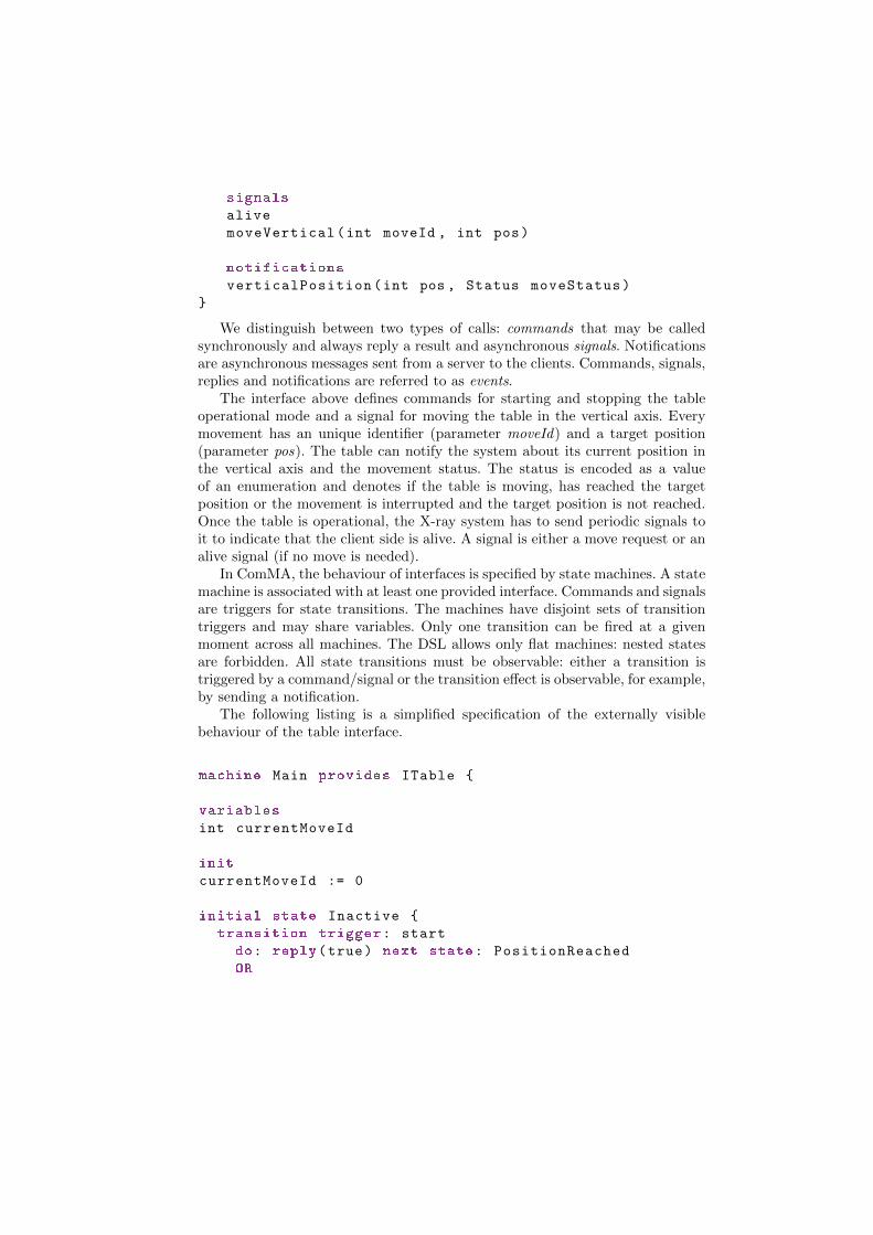
signals
alive
moveVertical(int moveId , int pos)
notifications
verticalPosition(int pos , Status moveStatus)
}
We distinguish between two types of calls: commands that may be calledsynchronously and always reply a result and asynchronous signals. Notificationsare asynchronous messages sent from a server to the clients. Commands, signals,replies and notifications are referred to as events.
The interface above defines commands for starting and stopping the tableoperational mode and a signal for moving the table in the vertical axis. Everymovement has an unique identifier (parameter moveId) and a target position(parameter pos). The table can notify the system about its current position inthe vertical axis and the movement status. The status is encoded as a valueof an enumeration and denotes if the table is moving, has reached the targetposition or the movement is interrupted and the target position is not reached.Once the table is operational, the X-ray system has to send periodic signals toit to indicate that the client side is alive. A signal is either a move request or analive signal (if no move is needed).
In ComMA, the behaviour of interfaces is specified by state machines. A statemachine is associated with at least one provided interface. Commands and signalsare triggers for state transitions. The machines have disjoint sets of transitiontriggers and may share variables. Only one transition can be fired at a givenmoment across all machines. The DSL allows only flat machines: nested statesare forbidden. All state transitions must be observable: either a transition istriggered by a command/signal or the transition effect is observable, for example,by sending a notification.
The following listing is a simplified specification of the externally visiblebehaviour of the table interface.
machine Main provides ITable {
variables
int currentMoveId
init
currentMoveId := 0
initial state Inactive {
transition trigger: start
do: reply(true) next state: PositionReached
OR
do: reply(false) next state: Inactive
}
state PositionReached {
transition trigger: moveVertical(int moveId , int target)
guard: moveId != currentMoveId
do: currentMoveId := moveId
next state: Moving
transition trigger: moveVertical(int moveId , int target)
guard: moveId == currentMoveId
next state: PositionReached
transition trigger: alive next state: PositionReached
transition
do: verticalPosition (*, Status :: PosReached)
next state: PositionReached
transition trigger: stop do: reply
next state: Inactive
}
state PositionNotReached {
...
}
state Moving {
transition trigger: moveVertical(int moveId , int target)
do: currentMoveId := moveId
next state: Moving
transition
do: verticalPosition (*, Status :: PosReached)
next state: PositionReached
transition
do: verticalPosition (*, Status :: PosNotReached)
next state: PositionNotReached
transition
do: verticalPosition (*, Status :: InMove)
next state: Moving
}
}
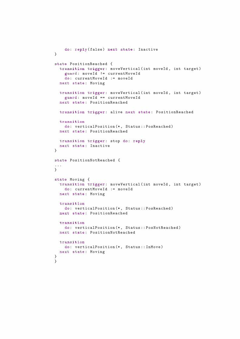
The command start tries to activate the table. The result is indicated in thereturn value. If the activation is successful, the table assumes a reached positionstate. It can receive a move request with a given identifier (signal moveVerticalwith a positive integer as identifier and a target position). If it is a new moverequest, the table starts moving (represented by state Moving). The table is mov-ing as long as it receives move requests. The movement status is continuouslyreported via notifications verticalPosition. The listing shows three different tran-sitions that send verticalPosition as a notification: one for each possible status.The notation ’*’ denotes a value that is unknown in the state machine. The statePositionNotReached is not elaborated. It is similar to state PositionReached.
If the table stops receiving the signal moveVertical, the movement is inter-rupted and a notification for ’position not reached’ status is sent. The machinethen moves to PositionNotReached state. The machine above does not capturethis logic. It just states that at any moment a transition to a non-moving stateis possible. The described behaviour is captured in a timing constraint explainedin the next section.
5 Monitoring of Time and Data Constraints
Issues at system level are often traced back to issues related to the conformanceof components (possibly supplied by a third party) to their interface specifica-tions. Many issues of this kind are manifested during the interaction of severalcomponents and it is difficult to detect them if a component is tested in isola-tion. Monitoring and checking component interactions can reveal the problemsat an earlier phase and help in analyzing logs harvested from systems in the field.We applied available runtime verification techniques (mainly inspired by [1]) tosupport specification and monitoring of interface behaviour and constraints ontiming and data.
5.1 General Scheme for Component Monitoring
Generally, runtime verification is a technique for checking system behaviouragainst a property during the execution of the system. The general scheme [7]is given in Fig. 3.
The property may be given in a formal specification language (automata,logic formula, grammar), as a set of rules or a program. A monitor is derivedfrom a set of properties. The task of the monitor is to observe the executionof the system and to produce a verdict, that is, a statement if the observationsatisfies the properties. The observation may be a series of system states or aseries of input and output events. Monitoring is executed either step by stepalong with the system execution or over a log that contains the observations.
Fig. 4 shows how this general approach is applied in ComMA. The behavioralmodel of the interfaces (state machines, timing and data rules) plays the role ofproperties. The monitor processes events observed during component executions.Currently the events are obtained in two ways: by logging during executions or

Fig. 3. General scheme of runtime verification
by monitoring network traffic when the component is deployed on the company-specific middleware. It should be noted that currently the execution trace ischecked after it is finished, that is, the check does not happen at runtime. Theimplementation of the monitor, however, is agnostic about the exact momentwhen events are supplied (during or after component execution). Monitoring atruntime can be performed if instrumentation is applied to components or to themiddleware layer.
Fig. 4. Monitoring in ComMA
The monitor is a POOSL program that is partially synthesized from theconstraint rules. It receives the events in the execution trace and sends them toan executable model (also a POOSL program) derived from the state machines.The state machine responds with events that are compared to the events in thetrace. The monitor also checks if the constraints hold for the trace. Verdictscan be errors and warnings. Errors are violations of the state machine logic.
Warnings are violations of constraints. Errors stop the monitoring process, aftera warning the monitoring continues.
In the following subsections we elaborate on the support for specifying andmonitoring constraints.
5.2 Timing Constraints
The first type of constraints are timing constraints defined as timing rules. Theygive the admissible intervals between events in different contexts. There are fourrule types.
Interval rules constrain the allowed time interval for observing an event ifa given preceding event was observed. The example rule named timeForReplystates that if the command stop is observed then the reply must be observedbetween 10 and 20 ms after the command. The rule is checked on the first oc-currence of reply after the command. Before checking timing rules, static checksensure that every command is properly matched by a reply. Pairs of command-s/replies are reconstructed in the order of their handling by the component.
timeForReply
command stop -[10.0 ms .. 20.0 ms] -> reply
The second rule type is called conditional interval. It states that if two eventsare observed without observing the first event in between then the interval be-tween them lies within a certain boundary. The next example states that theinterval between start and a positive reply is 30 ms. The rule will not be appliedif the reply is false.
intervalBetweenEvents
command start
and
reply(true)
-> [ .. 30.0 ms] between events
The third rule type allows specifications of periodic events. The followingrule states that after starting the system the connection should be kept aliveby sending signals every 100 ms. It is also possible to specify a jitter for theexpected period.
continousCommunication
reply(true) to command start then
any signal with period 100.0 ms jitter 10.0 ms
until
command stop
The fourth rule type allows stating that if a certain event is observed thenanother event must be absent during a given interval after the observation. Thefour types of rules can be combined in groups that form a scenario. Scenariosand the rule for absence of an event are illustrated in the following example. It isbased on the safety mechanisms implemented in the table control. One of them

states that if a move request is delayed for more than 200 ms during movement,the table must stop moving. The time for stopping after detecting the delay isalso constrained. The scenario specifies this constraint. The first rule acts as aprecondition: it detects if a move request is absent within 200 ms after receivingthe previous move request. If this happens then the table must stop within 1second after the delay is detected. The stop is manifested by the notificationverticalPosition with the corresponding status value.
group intervalForStopping
in state Moving signal moveVertical
-> absent signal moveVertical in [.. 200.0 ms]
- [.. 1000.0 ms] ->
notification verticalPosition (*, Status :: PosNotReached)
end group
This rule illustrates also the possibility to specify state information in timingrules. The rule will be triggered only if the signals are received in state Moving.This is possible because the rules are evaluated over events that are alreadyaccepted by the state machine, that is, state information is available.
5.3 Data Constraints
Apart from detecting delayed requests, other safety mechanisms in our industrialcase check the distance that the table is allowed to move after detecting theabsence of move requests. The distance should not exceed a certain value. Thisis schematically given below by showing the expected sequence of events whenthe table stops if move requests are no longer received:
verticalPosition(X, InMove)
moveVertical //The last moveVertical
... no more moveVertical signals ...
...
verticalPosition(Y, PosNotReached)
In order to check the distance we need to identify the last reported ver-tical position (say X) in the verticalPosition notification just before the lastmoveVertical signal. The fact that the table stops is indicated by a notificationverticalPosition with status PosNotReached and position Y. The absolute valueof Y-X must not exceed a certain limit.
We introduced a simple language for specifying data constraints. At an in-tuitive level, the meaning of a data constraint rule is: if a certain sequence ofevents is observed then the observed data values must satisfy a given condition.The monitoring algorithm should allow the observed data values to be boundto variables and then used in conditions. The specification of an expected eventsequence can be done by using a regular expression-like notation. It should bepossible to assert both the presence and the absence of events.
The following example shows the constraint expressed in the data constraintslanguage.
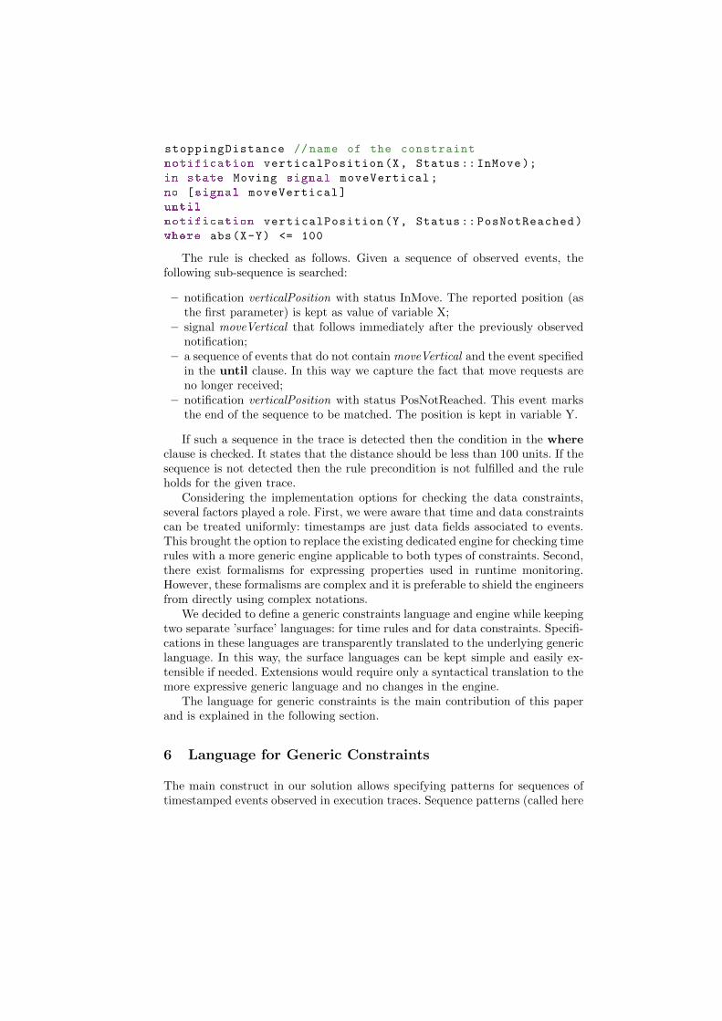
stoppingDistance //name of the constraint
notification verticalPosition(X, Status :: InMove );
in state Moving signal moveVertical;
no [signal moveVertical]
until
notification verticalPosition(Y, Status :: PosNotReached)
where abs(X-Y) <= 100
The rule is checked as follows. Given a sequence of observed events, thefollowing sub-sequence is searched:
– notification verticalPosition with status InMove. The reported position (asthe first parameter) is kept as value of variable X;
– signal moveVertical that follows immediately after the previously observednotification;
– a sequence of events that do not contain moveVertical and the event specifiedin the until clause. In this way we capture the fact that move requests areno longer received;
– notification verticalPosition with status PosNotReached. This event marksthe end of the sequence to be matched. The position is kept in variable Y.
If such a sequence in the trace is detected then the condition in the whereclause is checked. It states that the distance should be less than 100 units. If thesequence is not detected then the rule precondition is not fulfilled and the ruleholds for the given trace.
Considering the implementation options for checking the data constraints,several factors played a role. First, we were aware that time and data constraintscan be treated uniformly: timestamps are just data fields associated to events.This brought the option to replace the existing dedicated engine for checking timerules with a more generic engine applicable to both types of constraints. Second,there exist formalisms for expressing properties used in runtime monitoring.However, these formalisms are complex and it is preferable to shield the engineersfrom directly using complex notations.
We decided to define a generic constraints language and engine while keepingtwo separate ’surface’ languages: for time rules and for data constraints. Specifi-cations in these languages are transparently translated to the underlying genericlanguage. In this way, the surface languages can be kept simple and easily ex-tensible if needed. Extensions would require only a syntactical translation to themore expressive generic language and no changes in the engine.
The language for generic constraints is the main contribution of this paperand is explained in the following section.
6 Language for Generic Constraints
The main construct in our solution allows specifying patterns for sequences oftimestamped events observed in execution traces. Sequence patterns (called here

just sequence) are used to construct formulas which are evaluated during moni-toring.
A sequence is a concatenation of steps. Each step matches one or more ob-served events in a trace. There are three kinds of steps: event selector, a dis-junction of event selectors, and two until operators (weak and strong) inspiredby the similar constructs in LTL. Informally, the matching process starts fromthe first step in a sequence and tries to match it with the first event in a giventrace. If successful, the process continues with the next steps that are matchedagainst the remaining events in the trace. During this process free variables inthe pattern are bound to matched values and become available in the next steps.The following example shows the formulation of the stoppingDistance data con-straint rule of Section 5.3 in the generic language.
stoppingDistance
<t1 , in state Moving
notification verticalPosition(X, InMove)>;
<t2 , in state Moving signal moveVertical >;
<t3 , not [signal moveVertical]>
until
<t4 , notification verticalPosition(Y, PosNotReached)>
where
abs(X-Y) <= 100
This rule has a name and a formula. The formula specifies a sequence (thepart before the where keyword) and a condition that uses variables in thesequence (the part after where). The main difference with the syntax of thesame rule expressed in the data constraints language is the presence of timestampvariables (t1, t2, ...).
The first step in the example sequence is an event selector. It has a variablenamed t1 that is bound to the event timestamp. The until construct with ageneral form Selector1 until Selector2 matches a sequence of events in whichthe last event matches Selector2 and all the preceding events match Selector1.As can be seen in the example, event patterns can be negated. Selectors mayalso have a boolean condition that is evaluated if the event pattern matches (thisis shown in the following examples). The remaining part of this section definesthe syntax and semantics of the generic constraints language.
6.1 Language Syntax
The syntax rules of the language are given in Table 1. In these rules some non-terminals are left undefined: S is a set of states, Cond is a Boolean expressiondefined by the ComMA grammar, Var denotes a variable, and P (event pa-rameters) is a vector of variables and constants of types supported by ComMA.States, conditions and parameters can be omitted. For simplicity, the type of theevent (command, signal, etc.) is skipped and in state is abbreviated to in. We

Table 1. Syntax of the Generic Constraints Language
Formula F ::= Seq | Seq and Cond | Seq cf F | not F | F or F
Sequence Seq ::= Step | Step until Step | Stepwuntil Step | Seq ; Seq
Step Step ::= ES | ES or ... or ES
Event Selector ES ::= 〈V ar,E,Cond〉| 〈V ar, V ar,E,Cond〉Event Pattern E ::= in S EvDes(P ) | not [in S EvDes(P )]
Event Designator EvDes ::= eventName | ∗
assume that every variable appears at most once in all event selectors. The usageof variables in conditions has to be well-formed: no forward variable referencesare allowed.
From the rules it can be seen that event selectors have two forms. The firstone was already explained by the example rule stoppingDistance. The secondone has an extra variable called occurrence counter. The value of the variable isincremented every time the event selector is successfully matched in a sequence.Consider the following example that uses an occurrence counter:
<t1 , i, in state s A>
or
<t2 , not[in state s A]>
until
<t3 , B>
If this sequence is evaluated against a trace, the counter i will be incrementedevery time an event A is observed in state s until event B is observed. The usageof counters is exemplified further in the context of periodic time rules.
Operator cf stands for conditional follow and expresses a common case inwhich the match of a sequence is a precondition for checking a formula over theremaining part of the trace. For example, the formula:
<t1 , A>;
<t2 , not[in state s B]>
until
<t3 , C>
cf
<t4 , D>
is used to check if all sequences of events that start with A, end with C and donot contain event B occurring in state s, are immediately followed by event D.
Some useful logical operations are defined as the following abbreviations:
– F1 and F2 ≡ not (not F1 or not F2)
– F1 implies F2 ≡ not F1 or F2
– Seq where Cond ≡ not Seq or (Seq and Cond)

6.2 Language Semantics
Formulas are evaluated on traces of events. An event Ev is a tuple 〈t, s, e(D)〉where
– t is a non-negative real number denoting the timestamp of the event. Times-tamps form an increasing sequence;
– s is the state in which the event occurs. The event occurs in exactly onestate due to the constraints on the state machine syntax and semantics;
– e is event name and D = (d1, ..., dn) is a possibly empty vector of constants(event parameters).
A trace is obtained from a monitored sequence of timestamped events thatsatisfies the state machine behaviour. The process of monitoring adds state in-formation to the events. Trace T is a sequence of events Ev0, Ev1, ..., Evi, .... Foran integer i ≥ 0, we denote T i = Evi, Evi+1, ... and T (i) = Evi = 〈ti, si, ei(Di)〉.
Bindings of variables in event selectors are captured in environments. Wedefine an environment Γ = {[v1 7→ d1], ...} as a set of mappings from variablesto values. Γ [Γ ′] is the familiar operation of updating Γ with the mappings in Γ ′
and Γ (v) gives the value of v in Γ .For an environment Γ and a boolean expression Cond, we denote Γ |= Cond
if Cond evaluates to true for the valuations in Γ .When a sequence is matched in a trace, the environment with bound variables
and the remaining part of the trace are propagated to the possible next steps.This is formalized as a partial function Cont : Trace×Env×Seq → Trace×Env.Env is a set of environments and Trace is a set of traces.
We define a satisfaction relation between events, environments and eventpatterns as follows:
– (〈t, s, e(D)〉, Γ ) |= in S EvDes(P ) iff EvDes = e or EvDes = ∗, s ∈ S, forevery constant ci in P , ci = di and for the list of variables v1 . . . vk in P wehave Γ = {[v1 7→ d1], . . . , [vk 7→ dk]}
– (〈t, s, e(D)〉,∅) |= not[in S EvDes(P )] iff for all Γ ,(〈t, s, e(D)〉, Γ ) 2 in S EvDes(P )
If the set of states S and parameters P are not used in the event pattern,the corresponding checks are skipped.
The semantics of formulas is defined as satisfaction relation between formulas,traces and environments. We start with the semantics of sequences.
– (T, Γ ) |= 〈V ar,E,Cond〉 iff (T (0), Γm) |= E and Γ ′ |= Cond, where Γ ′ =Γ [Γm][V ar 7→ t0]
Cont(T, Γ, 〈V ar,E,Cond〉) = 〈T 1, Γ ′〉
– (T, Γ ) |= 〈V ar1, V ar2, E, Cond〉 iff (T, Γ ) |= 〈V ar1, E, Cond〉
Cont(T, Γ, 〈V ar1, V ar2, E, Cond〉) = 〈T 1, Γ ′[V ar2 7→ Γ (V ar2) + 1]〉 whereCont(T, Γ, 〈V ar1, E, Cond〉) = 〈T 1, Γ ′〉. Every occurrence counter takes ini-tial value 0 before a formula is evaluated on a trace.

– (T, Γ ) |= ES1 or...orESn iff there exist i such that 1 ≤ i ≤ n, (T, Γ ) |= ESi
Cont(T, Γ,ES1 or...or ESn) = 〈T 1, Γ [⋃k
(Γk \ Γ )]〉, for all k such that
(T, Γ ) |= ESk and Cont(T, Γ,ESk) = 〈T 1, Γk〉
It should be noted that⋃k
(Γk \ Γ ) cannot contain two different bindings for
the same variable because a variable can occur at most once in all ESk.
– (T, Γ ) |= Step1 untilStep2 iff there exist i such that i ≥ 0, (T i, Γ i) |= Step2and for each k, 0 ≤ k<i, (T k, Γ k) |= Step1 and (T k, Γ k) 2 Step2 whereenvironments are defined as:• Γ 0 = Γ• Cont(T k, Γ k, Step1) = 〈T k+1, Γ k+1〉 for all k, 0 ≤ k<i
Cont(T, Γ, Step1 until Step2) = Cont(T i, Γ i, Step2)
– (T, Γ ) |= Step1 wuntil Step2 iff:• (T, Γ ) |= Step1 until Step2Cont(T, Γ, Step1 wuntil Step2) = Cont(T, Γ, Step1 until Step2)
or• (T i, Γ i) |= Step1, for all i ≥ 0 and Γ i defined as in the case of until.Cont is undefined
– (T, Γ ) |= Seq1;Seq2 iff (T, Γ ) |= Seq1, Cont(T, Γ, Seq1) is defined and hasvalue 〈T i, Γ ′〉 for some i ≥ 1, and (T i, Γ ′) |= Seq2
Cont(T, Γ, Seq1;Seq2) = Cont(T i, Γ ′, Seq2)
– (T, Γ ) |= Seq andCond iff (T, Γ ) |= Seq, Cont(T, Γ, Seq) is defined and hasvalue 〈T i, Γ ′〉 and Γ ′ |= Cond
– (T, Γ ) |= Seq cf F iff• (T, Γ ) |= not Seq
or• (T, Γ ) |= Seq, Cont(T, Γ, Seq) = 〈T i, Γ ′〉 is defined and (T i, Γ ′) |= F
– (T, Γ ) |= not F if (T, Γ ) 2 F
– (T, Γ ) |= F1 or F2 if (T, Γ ) |= F1 or (T, Γ ) |= F2
We state that a formula F holds in a trace T and an initial environment Γif for every i ≥ 0, (T i, Γ ) |= F . The initial environment gives 0 as a value ofall occurrence counter variables. For the other variables the user can supply aninitial value or a default value is assumed.
During monitoring, time and data constraints are translated to formulas inthe presented generic language. The translation is automatic and transparentto the users. Hence, the users do not need to work directly with the genericformulas which are often more verbose and more difficult to grasp than thesource constraints. We first show how time rules are translated.

6.3 Translation of Timing Constraints
In this section we show how different types of timing rules are translated intoformulas in the generic constraints language.
Timing rules use a simplified event selectors of the form inSe(P ), where P isa possibly empty vector of constants. The set of states S and the parameters canbe omitted. The translation of event selectors in timing rules to the selectors inthe generic language is trivial and will not be discussed. Selectors will be givenin capital letters A, B,...
Interval Rule. The general form is:
A -[p..q] -> B
A and B are selectors, [p..q] denotes a time interval with an obvious constraint0 ≤ p < q. q may be infinity. The interval rule is translated to the followingformula:
<t1 , A>
cf
<t2 , not[B]>
until
<t3 , B, (t3 -t1) in [p..q]>
The formula states that if a match of A is observed then there must be anoccurrence of event that matches B and the first such occurrence is in the interval[p, q].
Conditional Interval Rule. The rule gives two events as a premise of the ruleand an expected interval.
A and B -> [p..q] between events
The rule is translated to:
<t1 , A>; <t2 , not[A]> until <t3, B>
where (t3-t1) in [p..q]
Absence of Event. The rule specifies an event that is a condition for notobserving a follow up event in a certain interval.
A -> absent B in [p..q]
The corresponding formula is:
not
(<t1 , A>;
<t2 , *, t2 -t1 <= q>
until
<t3 , B, (t3 -t1) in [p..q]>)

Periodic event rule. The rule specifies a triggering event A as a condition fora periodic observation of B with a period p and jitter j until a stop event C isobserved.
A then B with period p and jitter j until C
The meaning of the rule is that if an event A is observed at time t then thei-th occurrence of event B after A and before C must be in the time interval[t+ i ∗ p− j, t+ i ∗ p+ j]. The formula for this rule is:
<t, A>
cf
(<t1 , i, B, t1 in [t + (i + 1)*p -j, t + (i + 1)*p + j]>
or
<t2 , not[B], t2 <= t + (i + 1)*p + j>)
wuntil
<t3 , C, t3 <= t + (i + 1)*p + j>
The rule uses an event selector with occurrence counter i. If an event A isobserved then we check if the formula after ’cf’ is satisfied for the events followingA. The timestamp of A is bound to the variable t. There are three cases:
– we observe event B with timestamp t1. The condition of the first step in thedisjunction checks if t1 is in the allowed interval. If it is not, the formula isnot satisfied. If the condition is true (i.e. the occurrence is in the expectedinterval) the value of i is incremented and used to calculate the time intervalof the eventual next occurrence of B ;
– we observe an event different from B and C. In this case, the second com-ponent of the disjunction matches the event and we check the condition. Ifthe condition is false this means that after the last occurrence of B we havenot observed an event B and we have just observed an event that is alreadyafter the allowed interval. Therefore the formula is not satisfied;
– we observe event C. The condition checks if C is observed within the expectedtime upper bound for the event B. If the condition is false we have thesituation in the previous case: B is not found in the expected interval andwe have an event after this interval.
The semantics of the rule admits the case when C is never observed. wuntilis used to handle this.
The translation of periodic time rules illustrates that the resulting genericformulas may be more complex and more difficult to read than the original timeconstraint. We recall that users do not work with generic formulas directly. Theyuse the more compact syntax of the surface languages.
Group Time Rule. This rule type allows specifying a rule that is a precon-dition for a series of interval rules thus allowing a scenario of several events.We will only show the case when an absence of event may be followed by otherevents with given time intervals. An example was shown in the previous section.The general form is:

group
A -> absent B in [0 .. p]
- [p1 .. q1] -> C
- [p2 .. q2] -> D
...
end group
This rule is translated to the formula:
<t1 , A>;
<t2 , not[B], (t2-t1) <= p>
wuntil
<t3 , *, (t3 -t1) > p>
implies
<t4 , A>; <t5 , *> until <t6 , C, t6 -t4 -p in [p1..q1]>;
<t7 , not[D]> until <t8, D, t8-t6 in [p2..q2]>;
....
6.4 Translation of Data Constraints
The grammar for data constraints rules is in Table 2. This language is as a subsetof the generic constraints language following the same semantics.
Table 2. Syntax of Data Constraints Language
Data Constraint DConstraint ::= Seq where Cond
Sequence Seq ::= Step | Step until Step | Seq ; Seq
Step Step ::= in S EvDes(P ) | not [in S EvDes(P )]
Event Designator EvDes ::= eventName | ∗
6.5 Implementation Considerations
The definition of semantics for the generic constraints allows a proof that theinitial semantics of time rules is preserved by the translation to the genericlanguage. Generally, the development of the formalization enabled better under-standing of the subtle details and greatly supported the software implementation.
An important aspect of the implementation is the fact that in a practicalsetting we deal with finite traces whereas the semantics of the formulas is givenover infinite traces. This affects the evaluation of formulas. Consider an intervaltiming rule. In the trace we may observe the first event and according to the rulewe must observe the second event within certain period of time. If the trace ends

before passing this period and no event is observed the rule evaluates to false.However, we cannot conclude if the second event will never appear because theinformation is not complete (monitoring has stopped). For situations like thiswe do not give a yes/no verdict for the rule. Instead, a warning is produced thatstates the rule has not been fully evaluated due to the termination of monitoring.As an alternative, the semantics can be defined for finite traces. This is a subjectof future investigation.
6.6 Application of Monitoring on the Industrial Case
Component monitoring was applied during the development of the client soft-ware for the operating table. The examples shown here are simplifications of theactual models. The real model and constraints are more complex and take intoaccount the complete interface and its behaviour. Several issues were revealed.For instance, movement requests with negative identifiers were sent by the clientand accepted by the component. This was detected as a violation of the modeland corrections were implemented in the software. The availability of explicittiming constraints allowed to experiment with different values for the alloweddelays. The experiments revealed situations in which some events occur earlierthan expected.
Generally, the process of modeling the intended behaviour of the interfacebased on textual documentation supported the engineers to explore cases inwhich the documentation was missing or the interpretation of the informationwas not clear. We also faced situations when the data constraints language wasnot expressive enough. In these cases, the constraints were successfully expressedin the generic language.
7 Concluding Remarks
The availability of precise component interface specifications enables early detec-tion of defects and ultimately supports the development of software with higherquality. In this paper we presented ComMA, a framework for interface behaviourspecification and focused on the support for runtime monitoring of timing anddata constraints. The DSLs in ComMA integrate techniques and results fromdifferent research areas and provide a single entry point for engineers to specifyand develop component interfaces.
The development of ComMA follows the industry-as-laboratory approach.DSLs are based on the concrete needs of the engineers and evolve following theseneeds. The developed languages are not business-specific and are not restrictedto the medical domain. They are aimed at problems that are found in otherdomains as well and utilize general techniques thus making the framework easilygeneralizable.
Acknowledgements. The anonymous reviewers are thanked for useful sug-gestions for improvement. We would like to thank Dirk-Jan Swagerman for hissupport and the collaborating teams at Philips for constructive feedback.

The second author is grateful to Ed Brinksma for the very pleasant collab-oration when Ed was the scientific director of the Embedded Systems Institute(currently TNO-ESI). With his very broad knowledge he was able to discussany topic with experts and he created an excellent environment for productiveindustry-as-lab projects. Moreover, Ed is thanked for the stimulating role in thecareer development of the second author.
References
1. Howard Barringer, David E. Rydeheard, and Klaus Havelund. Rule systems forrun-time monitoring: From Eagle to RuleR. In Sokolsky and Tasiran [13], pages111–125.
2. Ed Brinksma and Jozef Hooman. Dependability for high–tech systems: anindustry–as–laboratory approach. In Design, Automation & Test in Europe(DATE’08), pages 1226–1231. European Design and Automation Association(EDAA), 2008.
3. Manfred Broy, Doron A. Peled, and Georg Kalus, editors. Engineering DependableSoftware Systems, volume 34 of NATO Science for Peace and Security Series, D:Information and Communication Security. IOS Press, 2013.
4. Lilian Burdy, Yoonsik Cheon, David R. Cok, Michael D. Ernst, Joseph R. Kiniry,Gary T. Leavens, K. Rustan M. Leino, and Erik Poll. An overview of JML toolsand applications. STTT, 7(3):212–232, 2005.
5. Franck Cassez and Claude Jard, editors. Formal Modeling and Analysis of TimedSystems, 6th International Conference, FORMATS 2008, Saint Malo, France,September 15-17, 2008. Proceedings, volume 5215 of Lecture Notes in ComputerScience. Springer, 2008.
6. Feng Chen, Marcelo D’Amorim, and Grigore Rosu. A formal monitoring-basedframework for software development and analysis. In Proceedings ICFEM 2004,volume 3308 of LNCS, pages 357–372. Springer-Verlag, 2004.
7. Ylies Falcone, Klaus Havelund, and Giles Reger. A tutorial on runtime verification.In Broy et al. [3], pages 141–175.
8. Hongman Kim, David Fried, Peter Menegay, Grant Soremekun, and ChristopherOster. Application of integrated modeling and analysis to development of complexsystems. Procedia Computer Science, 16:98 – 107, 2013.
9. Martin Leucker and Christian Schallhart. A brief account of runtime verification.The Journal of Logic and Algebraic Programming, 78(5):293 – 303, 2009.
10. Bertrand Meyer. Object-Oriented Software Construction. Prentice-Hall, Inc., Up-per Saddle River, NJ, USA, 1st edition, 1988.
11. Joel Ouaknine and James Worrell. Some recent results in metric temporal logic.In Cassez and Jard [5], pages 1–13.
12. Colin Potts. Software-engineering research revisited. IEEE Software, 19(9):19–28,1993.
13. Oleg Sokolsky and Serdar Tasiran, editors. Runtime Verification, 7th InternationalWorkshop, RV 2007, Vancouver, Canada, March 13, 2007, Revised Selected Papers,volume 4839 of Lecture Notes in Computer Science. Springer, 2007.
14. Bart Theelen, Oana Florescu, Marc Geilen, Jinfeng Huang, Piet van der Putten,and Jeroen Voeten. Software/Hardware Engineering with the Parallel Object-Oriented Specification Language. In Proc. of MEMOCODE’07, pages 139–148.IEEE, 2007.